Technical Note: Guidelines for choosing and installing … · Technical Note 00840-0300-4024, Rev...
18
Technical Note 00840-0300-4024, Rev CE Rosemount Level Transmitters March 2018 Guidelines for Choosing and Installing Radar in Stilling Wells and Bypass Chambers 1.0 Introduction This document provides a guideline for choosing and installing Rosemount ™ Process radar devices in stilling wells and bypass chambers. Even though process radars generally provide robust operation installed in still pipes, all process radars regardless of make or type are designed to perform at their very best during free propagation. Installed in still pipes, the process radar’s accuracy may be affected due to the microwave propagation through the still pipe. For highest accuracy in still pipes, we have developed the Rosemount 5900 Radar Level Gauges with unique array antennas utilizing a low-loss microwave mode dedicated for still pipes. Refer to Rosemount 5900S Radar Level Gauge Product Data Sheet and Rosemount 5900C Radar Level Gauge Product Data Sheet for more information. Stilling wells and bypass chambers are used in many applications and many different types of tanks and vessels. The two installation methods will jointly be referred to as pipes. Radar transmitters can be used in these installations, but function differently in pipes than in normal vessel installations. This guide is intended to assist with radar device selection and installation for optimal performance. Figure 1. Example of a Bypass Chamber (Left) and a Stilling Well (Right) 2.0 Advantages of using bypass chambers and stilling wells Stilling wells and bypass chambers are used in many applications and many different types of tanks/vessels. The reasons for having the pipes in the vessels differ depending on the application but are typically beneficial from an application standpoint. See sections 2.1 through 2.4 for reasons to use pipes.
Transcript of Technical Note: Guidelines for choosing and installing … · Technical Note 00840-0300-4024, Rev...

Technical Note00840-0300-4024, Rev CE
Rosemount Level TransmittersMarch 2018
Guidelines for Choosing and Installing Radar in Stilling Wells and Bypass Chambers
1.0 IntroductionThis document provides a guideline for choosing and installing Rosemount™ Process radar devices in stilling wells and bypass chambers.
Even though process radars generally provide robust operation installed in still pipes, all process radars regardless of make or type are designed to perform at their very best during free propagation. Installed in still pipes, the process radar’s accuracy may be affected due to the microwave propagation through the still pipe. For highest accuracy in still pipes, we have developed the Rosemount 5900 Radar Level Gauges with unique array antennas utilizing a low-loss microwave mode dedicated for still pipes. Refer to Rosemount 5900S Radar Level Gauge Product Data Sheet and Rosemount 5900C Radar Level Gauge Product Data Sheet for more information.
Stilling wells and bypass chambers are used in many applications and many different types of tanks and vessels. The two installation methods will jointly be referred to as pipes. Radar transmitters can be used in these installations, but function differently in pipes than in normal vessel installations. This guide is intended to assist with radar device selection and installation for optimal performance.
Figure 1. Example of a Bypass Chamber (Left) and a Stilling Well (Right)
2.0 Advantages of using bypass chambers and stilling wellsStilling wells and bypass chambers are used in many applications and many different types of tanks/vessels. The reasons for having the pipes in the vessels differ depending on the application but are typically beneficial from an application standpoint. See sections 2.1 through 2.4 for reasons to use pipes.
Technical Note00840-0300-4024, Rev CE
Rosemount Level TransmittersMarch 2018
2 Rosemount Level Transmitters
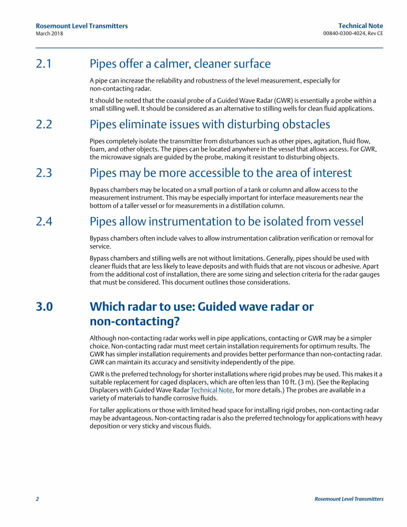
2.1 Pipes offer a calmer, cleaner surfaceA pipe can increase the reliability and robustness of the level measurement, especially for non-contacting radar.
It should be noted that the coaxial probe of a Guided Wave Radar (GWR) is essentially a probe within a small stilling well. It should be considered as an alternative to stilling wells for clean fluid applications.
2.2 Pipes eliminate issues with disturbing obstaclesPipes completely isolate the transmitter from disturbances such as other pipes, agitation, fluid flow, foam, and other objects. The pipes can be located anywhere in the vessel that allows access. For GWR, the microwave signals are guided by the probe, making it resistant to disturbing objects.
2.3 Pipes may be more accessible to the area of interestBypass chambers may be located on a small portion of a tank or column and allow access to the measurement instrument. This may be especially important for interface measurements near the bottom of a taller vessel or for measurements in a distillation column.
2.4 Pipes allow instrumentation to be isolated from vesselBypass chambers often include valves to allow instrumentation calibration verification or removal for service.
Bypass chambers and stilling wells are not without limitations. Generally, pipes should be used with cleaner fluids that are less likely to leave deposits and with fluids that are not viscous or adhesive. Apart from the additional cost of installation, there are some sizing and selection criteria for the radar gauges that must be considered. This document outlines those considerations.
3.0 Which radar to use: Guided wave radar or non-contacting?Although non-contacting radar works well in pipe applications, contacting or GWR may be a simpler choice. Non-contacting radar must meet certain installation requirements for optimum results. The GWR has simpler installation requirements and provides better performance than non-contacting radar. GWR can maintain its accuracy and sensitivity independently of the pipe.
GWR is the preferred technology for shorter installations where rigid probes may be used. This makes it a suitable replacement for caged displacers, which are often less than 10 ft. (3 m). (See the Replacing Displacers with Guided Wave Radar Technical Note, for more details.) The probes are available in a variety of materials to handle corrosive fluids.
For taller applications or those with limited head space for installing rigid probes, non-contacting radar may be advantageous. Non-contacting radar is also the preferred technology for applications with heavy deposition or very sticky and viscous fluids.
Technical Note 00840-0300-4024, Rev CE
Rosemount Level TransmittersMarch 2018
4.0 Installation guidelines for guided wave radar
4.1 Using GWR in pipes: Rigid or flexible?In most cases, rigid probes are preferred for pipe installations. When used in a metal, small diameter pipe, single rigid probes offer a stronger return signal than when used in open applications. This makes them suitable for low dielectric and interface applications. Flexible probes may be used in longer pipes, but care must be taken to assure that the probe is suspended in a true vertical position and does not touch the pipe wall.
If flexible probes are to be used, the pipes should be 4 in. (100 mm) or larger to allow room for some flexing. Also, as fluid moves into the pipe, it may push the probe towards the pipe wall. If the probe touches the wall, false reflections will create false level measurements. Rigid probes are less susceptible to these issues. Flexible probes simply need more room. Very narrow pipes allow little room for movement or flexing of the probe.
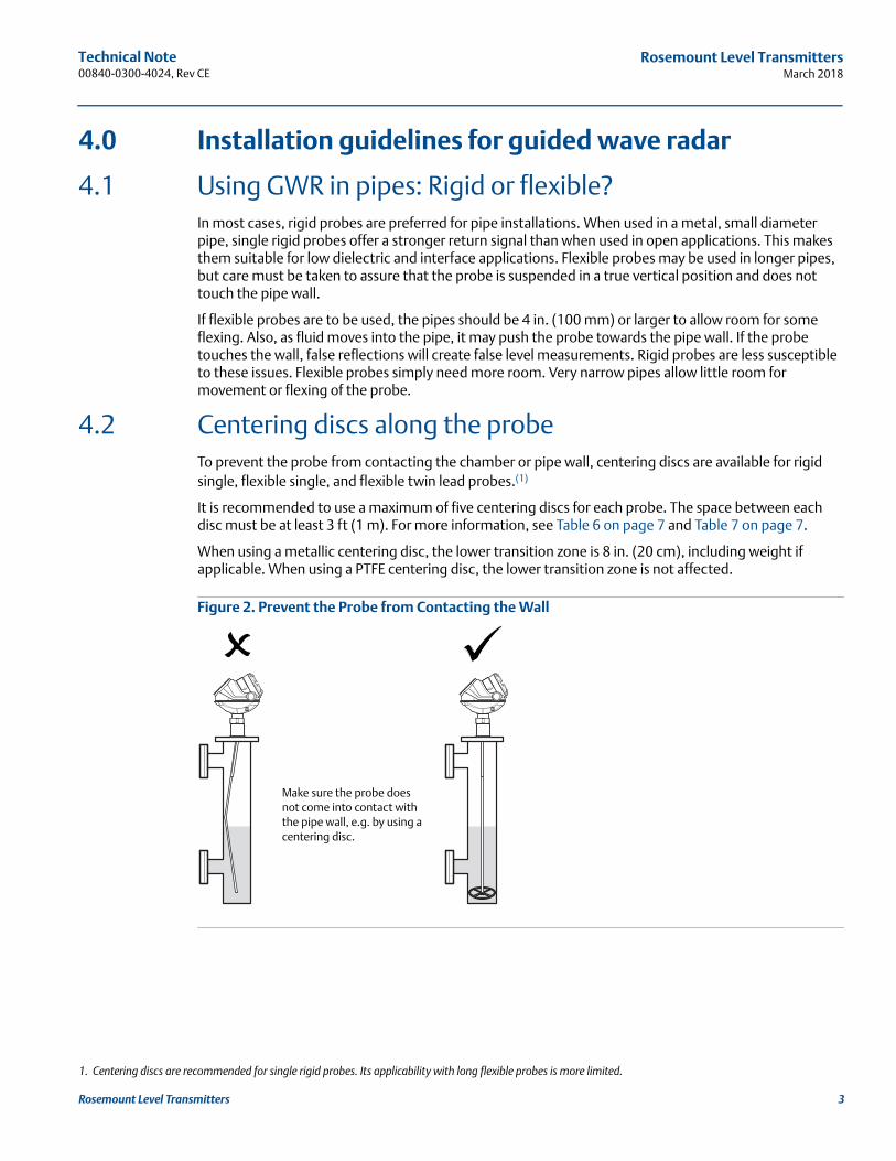
4.2 Centering discs along the probeTo prevent the probe from contacting the chamber or pipe wall, centering discs are available for rigid single, flexible single, and flexible twin lead probes.(1)
It is recommended to use a maximum of five centering discs for each probe. The space between each disc must be at least 3 ft (1 m). For more information, see Table 6 on page 7 and Table 7 on page 7.
When using a metallic centering disc, the lower transition zone is 8 in. (20 cm), including weight if applicable. When using a PTFE centering disc, the lower transition zone is not affected.
Figure 2. Prevent the Probe from Contacting the Wall
1. Centering discs are recommended for single rigid probes. Its applicability with long flexible probes is more limited.
Make sure the probe does not come into contact with the pipe wall, e.g. by using a centering disc.
3Rosemount Level Transmitters
Technical Note00840-0300-4024, Rev CE
Rosemount Level TransmittersMarch 2018
4 Rosemount Level Transmitters
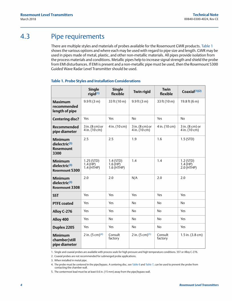
4.3 Pipe requirementsThere are multiple styles and materials of probes available for the Rosemount GWR products. Table 1 shows the various options and where each may be used with regard to pipe size and length. GWR may be used in pipes made of metal, plastic, and other non-metallic materials. All pipes provide isolation from the process materials and conditions. Metallic pipes help to increase signal strength and shield the probe from EMI disturbances. If EMI is present and a non-metallic pipe must be used, then the Rosemount 5300 Guided Wave Radar Level Transmitter should be used.
Table 1. Probe Styles and Installation Considerations
Single rigid(1)
1. Single and coaxial probes are available with process seals for high pressure and high temperature conditions. SST or Alloy C-276.
Single flexible
Twin rigidTwin
flexibleCoaxial(1)(2)
2. Coaxial probes are not recommended for submerged probe applications.
Maximum recommended length of pipe
9.9 ft (3 m) 33 ft (10 m) 9.9 ft (3 m) 33 ft (10 m) 19.8 ft (6 m)
Centering disc? Yes Yes No Yes No
Recommended pipe diameter
3 in. (8 cm) or 4 in. (10 cm)
4 in. (10 cm) 3 in. (8 cm) or 4 in. (10 cm)
4 in. (10 cm) 3 in. (8 cm) or 4 in. (10 cm)
Minimum dielectric(3) Rosemount 3300
3. When installed in metal pipe.
2.5 2.5 1.9 1.6 1.5 (STD)
Minimum dielectric(3) Rosemount 5300
1.25 (STD)1.4 (HP)1.4 (HTHP)
1.4 (STD)1.6 (HP)1.6 (HTHP)
1.4 1.4 1.2 (STD)1.4 (HP)2.0 (HTHP)
Minimum dielectric(3) Rosemount 3308
2.0 2.0 N/A 2.0 2.0
SST Yes Yes Yes Yes Yes
PTFE coated Yes Yes No No No
Alloy C-276 Yes Yes No No Yes
Alloy 400 Yes No No No Yes
Duplex 2205 Yes Yes No No Yes
Minimum chamber/still pipe diameter
2 in. (5 cm)(4)
4. The probe must be centered in the pipe/bypass. A centering disc, see Table 6 and Table 7, can be used to prevent the probe from contacting the chamber wall.
Consult factory
2 in. (5 cm)(5)
5. The centermost lead must be at least 0.6 in. (15 mm) away from the pipe/bypass wall.
Consult factory
1.5 in. (3.8 cm)

Technical Note 00840-0300-4024, Rev CE
Rosemount Level TransmittersMarch 2018
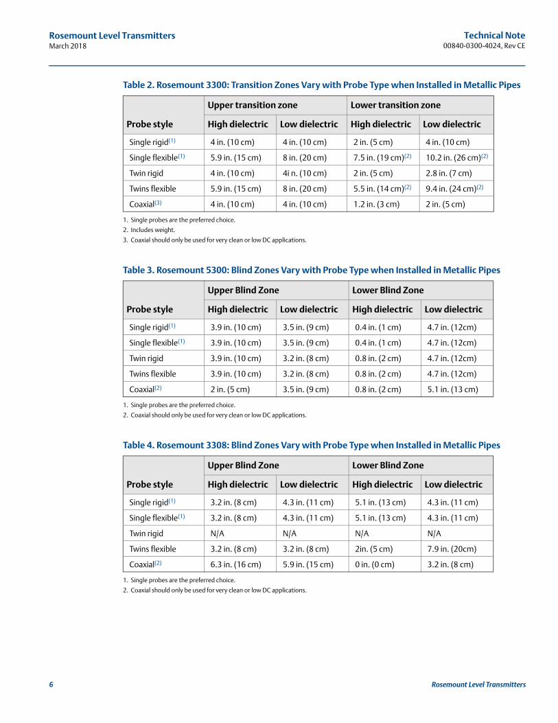
When sizing a probe for use in a bypass chamber, it is important to allow for some extra length for the transition zones and Blind Zones of the probe, see Figure 3 and Figure 4. Level measurements are compromised in these areas.
Figure 3. Rosemount 3300: Transition Zones
Figure 4. Rosemount 5300 and Rosemount 3308: Blind Zones
A. URV D. Probe length
B. LRV E. Lower transition zone
C. Upper transition zone
A. Upper Blind Zone C. Lower Blind Zone
B. Reduced accuracy
C
E
D
A
B
A
C
B
B
5Rosemount Level Transmitters
Technical Note00840-0300-4024, Rev CE
Rosemount Level TransmittersMarch 2018
6 Rosemount Level Transmitters
Table 2. Rosemount 3300: Transition Zones Vary with Probe Type when Installed in Metallic Pipes
Table 3. Rosemount 5300: Blind Zones Vary with Probe Type when Installed in Metallic Pipes
Table 4. Rosemount 3308: Blind Zones Vary with Probe Type when Installed in Metallic Pipes
Probe style
Upper transition zone Lower transition zone
High dielectric Low dielectric High dielectric Low dielectric
Single rigid(1)
1. Single probes are the preferred choice.
4 in. (10 cm) 4 in. (10 cm) 2 in. (5 cm) 4 in. (10 cm)
Single flexible(1) 5.9 in. (15 cm) 8 in. (20 cm) 7.5 in. (19 cm)(2)
2. Includes weight.
10.2 in. (26 cm)(2)
Twin rigid 4 in. (10 cm) 4i n. (10 cm) 2 in. (5 cm) 2.8 in. (7 cm)
Twins flexible 5.9 in. (15 cm) 8 in. (20 cm) 5.5 in. (14 cm)(2) 9.4 in. (24 cm)(2)
Coaxial(3)
3. Coaxial should only be used for very clean or low DC applications.
4 in. (10 cm) 4 in. (10 cm) 1.2 in. (3 cm) 2 in. (5 cm)
Probe style
Upper Blind Zone Lower Blind Zone
High dielectric Low dielectric High dielectric Low dielectric
Single rigid(1)
1. Single probes are the preferred choice.
3.9 in. (10 cm) 3.5 in. (9 cm) 0.4 in. (1 cm) 4.7 in. (12cm)
Single flexible(1) 3.9 in. (10 cm) 3.5 in. (9 cm) 0.4 in. (1 cm) 4.7 in. (12cm)
Twin rigid 3.9 in. (10 cm) 3.2 in. (8 cm) 0.8 in. (2 cm) 4.7 in. (12cm)
Twins flexible 3.9 in. (10 cm) 3.2 in. (8 cm) 0.8 in. (2 cm) 4.7 in. (12cm)
Coaxial(2)
2. Coaxial should only be used for very clean or low DC applications.
2 in. (5 cm) 3.5 in. (9 cm) 0.8 in. (2 cm) 5.1 in. (13 cm)
Probe style
Upper Blind Zone Lower Blind Zone
High dielectric Low dielectric High dielectric Low dielectric
Single rigid(1)
1. Single probes are the preferred choice.
3.2 in. (8 cm) 4.3 in. (11 cm) 5.1 in. (13 cm) 4.3 in. (11 cm)
Single flexible(1) 3.2 in. (8 cm) 4.3 in. (11 cm) 5.1 in. (13 cm) 4.3 in. (11 cm)
Twin rigid N/A N/A N/A N/A
Twins flexible 3.2 in. (8 cm) 3.2 in. (8 cm) 2in. (5 cm) 7.9 in. (20cm)
Coaxial(2)
2. Coaxial should only be used for very clean or low DC applications.
6.3 in. (16 cm) 5.9 in. (15 cm) 0 in. (0 cm) 3.2 in. (8 cm)

Technical Note 00840-0300-4024, Rev CE
Rosemount Level TransmittersMarch 2018
Table 5. Required Probe Length in Chambers
Table 6. Centering Disc Dimensions
Table 7. Centering Disc Size Recommendation for Different Pipe Schedules
Chamber manufacturer Probe length(1)
1. If flushing ring is used, add 1 in. (25 mm).
Major torque-tube manufacture (249B, 249C, 2449K, 249N, 259B)
Displacer+9 in. (229 mm)
Masoneilan™ (Torque tube operated), proprietary flange
Displacer+8 in. (203 mm)
Other - torque tube(2)
2. For other manufacturers, there are small variations. This is an approximate value, actual length should be verified.
Displacer+8 in. (203 mm)
Magnetrol® (spring operated)(3)
3. Lengths vary depending on model, SG and rating, and should be verified.
Displacer+between 7.8 in. (195 mm) to 15 in. (383 mm)
Others - spring operated(2) Displacer+19.7 in. (500 mm)
Disc size Actual disc diameter
2 in. 1.8 in. (45 mm)
3 in. 2.7 in. (68 mm)
4 in. 3.6 in. (92 mm)
6 in. 5.55 in. (141 mm)
8 in. 7.40 in. (188 mm)
Pipe size
Pipe schedule
5s,5 10s, 10 40s, 40 80s, 80 120 160
2-in. 2 in. 2 in. 2 in. 2 in. N/A(1)
1. Schedule is not available for pipe size.
N/A(2)
2. No centering disc is available.
3-in. 3 in. 3 in. 3 in. 3 in. N/A(1) 2 in.
4-in. 4 in. 4 in. 4 in. 4 in. 4 in. 3 in.
5-in. 4 in. 4 in. 4 in. 4 in. 4 in. 4 in.
6-in. 6 in. 6 in. 6 in. 6 in. 4 in. 4 in.
7-in. N/A(1) N/A(1) 5 in. 6 in. N/A(1) N/A(1)
8-in. 8 in. 8 in. 8 in. 8 in. 6 in. 6 in.
7Rosemount Level Transmitters

Technical Note00840-0300-4024, Rev CE
Rosemount Level TransmittersMarch 2018
8 Rosemount Level Transmitters
Table 8. Installation Parameters and Chamber Size Summary
Figure 5. Weight Dimensions
Installation parameter
Chamber diameter
2-in. 3-in. 4-in.
Rigid probe Ok Ok Ok
Flexible probe Not recommended Application dependent (use heavy weight)
Preferred
Coaxial probe Ok(1)
1. Application dependent based on coating properties of the liquid.
Ok(1) Ok(1)
Side connections, large (2 in.) Not recommended Application dependent Preferred
Side connections, small (1 in.) Ok Ok Ok
Overall length (< 2 m) Ok Ok Ok
Overall length (> 2 m) Application dependent (use centering discs/heavy weight)
Application dependent (use centering discs/heavy weight)
Ok
Low DC fluid (down to 1.4) Ok Ok Ok
High DC fluid Ok Ok Ok
Rapid fill rates Application dependent Ok Ok
Boiling, turbulence Application dependent Ok Preferred
Gas lift Application dependent Ok Preferred
Viscous, clogging fluids Application dependent, heat trace
Heat trace Heat trace
Chambers with interface Not recommended Not recommended Not recommended
Short weight: Long weight:
A. 2 in (50 mm); 4 mm SST probes A. 5.5 in (140 mm); 4 mm SST probes
B. 1.5 in (37.5 mm); 4 mm SST probes B. 1.5 in (37.5 mm); 4 mm SST probes
A
B

Technical Note 00840-0300-4024, Rev CE
Rosemount Level TransmittersMarch 2018
4.4 Stilling well requirementsPipes should be an all-metal material. Non-metallic pipes or sections are not recommended for non-contacting radar. Plastic, acrylic glass, or other non-metal materials do not shield the radar from outside disturbances and offer minimal, if any, application benefit. Other requirements include:
Pipe should have a constant inside diameter.
Pipe must be smooth on the inside (smooth pipe joints are acceptable, but may reduce accuracy).
Avoid deposits, rust, and gaps.
One hole above the product surface.
Minimum hole diameter is 0.25 in. (6 mm).
The hole diameter should be less than half of the diameter of the pipe, or maximum 4 in. (100 mm)(1). For example, a 4-in. pipe can have maximum 2-in. holes, and a 10-in. pipe can have maximum 4-in. holes.
Slots should be less than 12 in. (300 mm) long and 1.5 in. (40 mm) wide(1).
Figure 6. Still Pipe Requirements
NoteHoles/slots can be distributed around the pipe.
1. If slots/holes are larger than the above recommended figures, consult your local Emerson™ representative.
A. Ø: D/2, or maximum 4 in. (100 mm) C. Maximum 1.5 in. (40 mm)
B. Maximum 12 in. (300 mm) D. Pipe diameter
A
D
C
B
9Rosemount Level Transmitters

Technical Note00840-0300-4024, Rev CE
Rosemount Level TransmittersMarch 2018
10 Rosemount Level Transmitters
5.0 Installation guidelines for non-contacting radar
5.1 Using non-contacting radar in stilling wells and bypass chambersWhen radar transmitters are used in metallic pipes, the microwave signal is guided and contained within the pipe. This restriction of the signal results in a stronger signal on the surface which can be an advantage for low dielectric and/or turbulent applications. Non-contacting radar can be advantageous over longer distances especially when the use of GWR is not convenient.
5.2 The impact of frequencyWhen radar is used inside the pipe, more than one microwave mode is generated and each mode has a unique propagation speed. The number of microwave modes that are generated varies with the frequency of the radar signal and the pipe diameter. Emerson recommends using a 2- or 3-in. pipe to minimize the number of microwave modes. The use of higher frequency radar transmitters should be restricted to smaller diameters. Conversely, lower frequency units perform better than higher frequency units on larger diameter pipes. Non-contacting radar transmitters should not be used on pipes larger than 8-in.
Dirty pipes, heavy vapors and condensation can be dealt with by using a high frequency radar with high sensitivity (Rosemount 5408) or by a low frequency radar (Rosemount 5401).
Radars utilizing linear polarization (Rosemount 5408 and 5600) have better tolerance for installations that may not meet all mechanical requirements than radars utilizing circular polarization (Rosemount 5401 and 5402) because the transmitter head can be rotated to a point where the disturbances are reduced.
Rosemount 5401 Non-Contacting Level Transmitter is not recommended for chambers as its wider pulse frequency makes it sensitive to disturbances generated by the inlets and compromise level measurements near those areas.
Rosemount 5402 Non-Contacting Level Transmitter is not recommended for medias with strong reflections (i.e. water based, acids, etc) in chamber/still pipe installations.
5.3 Choosing the right antennaThe Rosemount 5400 and Rosemount 5600 Non-Contacting Level Transmitter offer a wide range of antennas, including rod antennas, cone antennas, and process seal antennas. Of these, the Cone antenna is the only suitable antenna for level measurement in pipes. All units are available with SST, Alloy C-276, and Alloy 400 antennas.
With any radar unit, the antenna should match the pipe size as closely as possible. The antennas are sized to fit within schedule 80 or lower pipes.
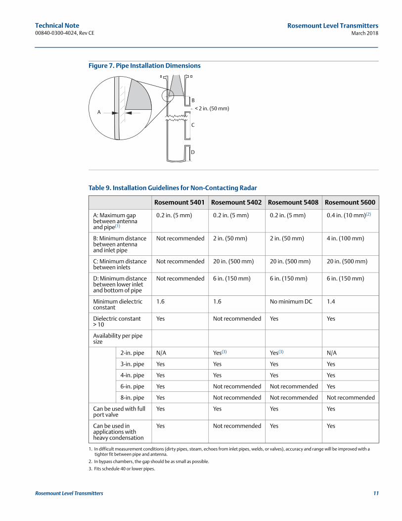
Ideally, the maximum gap between the antenna and the pipe wall should be as small as possible (see “A” in Figure 7 on page 11). For the Rosemount 5600, gaps of up to 0.4 in. (10 mm) are acceptable. For the Rosemount 5400 and 5408, gaps of up to 0.2 in. (5 mm) are acceptable. Larger gaps may result in inaccuracies.
Technical Note 00840-0300-4024, Rev CE
Rosemount Level TransmittersMarch 2018
Figure 7. Pipe Installation Dimensions
Table 9. Installation Guidelines for Non-Contacting Radar
Rosemount 5401 Rosemount 5402 Rosemount 5408 Rosemount 5600
A: Maximum gap between antenna and pipe(1)
1. In difficult measurement conditions (dirty pipes, steam, echoes from inlet pipes, welds, or valves), accuracy and range will be improved with a tighter fit between pipe and antenna.
0.2 in. (5 mm) 0.2 in. (5 mm) 0.2 in. (5 mm) 0.4 in. (10 mm)(2)
2. In bypass chambers, the gap should be as small as possible.
B: Minimum distance between antenna and inlet pipe
Not recommended 2 in. (50 mm) 2 in. (50 mm) 4 in. (100 mm)
C: Minimum distance between inlets
Not recommended 20 in. (500 mm) 20 in. (500 mm) 20 in. (500 mm)
D: Minimum distance between lower inlet and bottom of pipe
Not recommended 6 in. (150 mm) 6 in. (150 mm) 6 in. (150 mm)
Minimum dielectric constant
1.6 1.6 No minimum DC 1.4
Dielectric constant > 10
Yes Not recommended Yes Yes
Availability per pipe size
2-in. pipe N/A Yes(3)
3. Fits schedule 40 or lower pipes.
Yes(3) N/A
3-in. pipe Yes Yes Yes Yes
4-in. pipe Yes Yes Yes Yes
6-in. pipe Yes Not recommended Not recommended Yes
8-in. pipe Yes Not recommended Not recommended Not recommended
Can be used with full port valve
Yes Yes Yes Yes
Can be used in applications with heavy condensation
Yes Not recommended Yes Yes
< 2 in. (50 mm)A
B
C
D
11Rosemount Level Transmitters

Technical Note00840-0300-4024, Rev CE
Rosemount Level TransmittersMarch 2018
12 Rosemount Level Transmitters
5.4 Stilling well requirementPipes should be an all-metal material. Non-metallic pipes or sections are not recommended for non-contacting radar. Plastic, acrylic glass, or other non-metal materials do not shield the radar from outside disturbances and offer minimal, if any, application benefit. Other requirements include:
Pipe should have a constant inside diameter.
Pipe must be smooth on the inside (smooth pipe joints are acceptable, but may reduce accuracy).
Avoid deposits, rust, gaps and slots.
One hole above the product surface.
Minimum distance between holes is 6 in. (150 mm)(1).
Holes should be drilled on one side and de-burred.
Ball valve or other full port valves must be completely open.
Level will not be measured accurately below the pipe opening.
The length of the pipe should extend beyond minimum product level.
In heavy condensation applications, insulate the pipe/nozzle which is outside the tank atmosphere.
Failure to follow these requirements may affect the reliability of the level measurement.
Figure 8. Still Pipe Requirements
Table 10. Maximum Hole Diameter
1. The minimum distance between holes is not always the optimal distance. Consult factory or product documentation for best installation practices.
A. Minimum 6 in. (150 mm) B. Maximum hole diameter
Rosemount 5401 Rosemount 5402 Rosemount 5408 Rosemount 5600
0.8 in. (20 mm) 0.4 in. (10 mm) 1.0 in. (25 mm) 0.8 in. (20 mm)
A
B

Technical Note 00840-0300-4024, Rev CE
Rosemount Level TransmittersMarch 2018
In flat bottom tanks (<20° incline), where the fluid has a low dielectric and a measurement close to the bottom of the tank is desired, a deflection plate should be used. This will suppress the bottom echo and allow measurements closer to the pipe end. This is not necessary for dish- or cone-bottomed tanks where the slope is more than 20°.
Figure 9. Deflection Plate
5.5 Bypass chamber requirementsThe guidelines for stilling wells also apply to bypass chambers, with a few additions. Most importantly, the inlet pipes must not protrude into the measuring pipe and the edge should be as smooth as possible. In addition, the distances between the antenna and the chamber wall and inlet pipes should meet those shown in Table 9 on page 11. If the inlet pipe tolerances are too restrictive, an alternative solution may be to mount a smaller pipe within the bypass chamber, or consider using GWR.
Figure 10. Maximum Antenna Inclination in Chamber Installations
When the transmitter is mounted in a pipe, the inclination should be within 1° of vertical. Even small deviations can cause large measurement errors. Also, the cone should be mounted in the center of the pipe to achieve a uniform gap around the antenna.
<1°
13Rosemount Level Transmitters
Technical Note00840-0300-4024, Rev CE
Rosemount Level TransmittersMarch 2018
14 Rosemount Level Transmitters
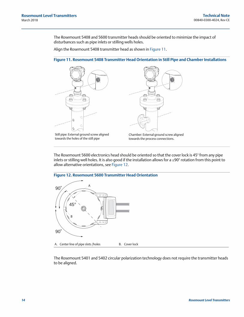
The Rosemount 5408 and 5600 transmitter heads should be oriented to minimize the impact of disturbances such as pipe inlets or stilling wells holes.
Align the Rosemount 5408 transmitter head as shown in Figure 11.
Figure 11. Rosemount 5408 Transmitter Head Orientation in Still Pipe and Chamber Installations
The Rosemount 5600 electronics head should be oriented so that the cover lock is 45° from any pipe inlets or stilling well holes. It is also good if the installation allows for a ±90° rotation from this point to allow alternative orientations, see Figure 12.
Figure 12. Rosemount 5600 Transmitter Head Orientation
The Rosemount 5401 and 5402 circular polarization technology does not require the transmitter heads to be aligned.
A. Center line of pipe slots /holes B. Cover lock
Still pipe: External ground screw aligned towards the holes of the still pipe
Chamber: External ground screw aligned towards the process connections.
90˚
90˚
45°
A
B
Technical Note 00840-0300-4024, Rev CE
Rosemount Level TransmittersMarch 2018
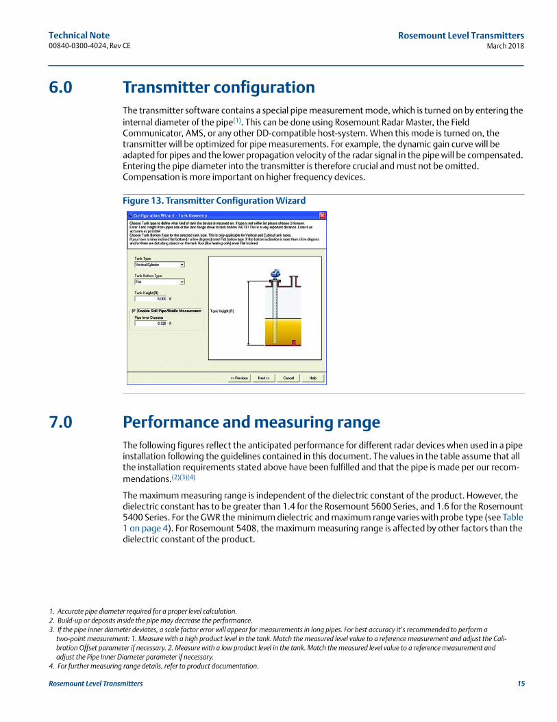
6.0 Transmitter configurationThe transmitter software contains a special pipe measurement mode, which is turned on by entering the internal diameter of the pipe(1). This can be done using Rosemount Radar Master, the Field Communicator, AMS, or any other DD-compatible host-system. When this mode is turned on, the transmitter will be optimized for pipe measurements. For example, the dynamic gain curve will be adapted for pipes and the lower propagation velocity of the radar signal in the pipe will be compensated. Entering the pipe diameter into the transmitter is therefore crucial and must not be omitted. Compensation is more important on higher frequency devices.
Figure 13. Transmitter Configuration Wizard
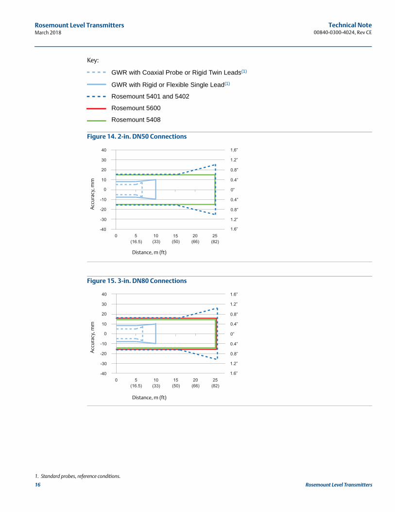
7.0 Performance and measuring rangeThe following figures reflect the anticipated performance for different radar devices when used in a pipe installation following the guidelines contained in this document. The values in the table assume that all the installation requirements stated above have been fulfilled and that the pipe is made per our recom-mendations.(2)(3)(4)
The maximum measuring range is independent of the dielectric constant of the product. However, the dielectric constant has to be greater than 1.4 for the Rosemount 5600 Series, and 1.6 for the Rosemount 5400 Series. For the GWR the minimum dielectric and maximum range varies with probe type (see Table 1 on page 4). For Rosemount 5408, the maximum measuring range is affected by other factors than the dielectric constant of the product.
1. Accurate pipe diameter required for a proper level calculation.2. Build-up or deposits inside the pipe may decrease the performance.3. If the pipe inner diameter deviates, a scale factor error will appear for measurements in long pipes. For best accuracy it’s recommended to perform a
two-point measurement: 1. Measure with a high product level in the tank. Match the measured level value to a reference measurement and adjust the Cali-bration Offset parameter if necessary. 2. Measure with a low product level in the tank. Match the measured level value to a reference measurement and adjust the Pipe Inner Diameter parameter if necessary.
4. For further measuring range details, refer to product documentation.
15Rosemount Level Transmitters
Technical Note00840-0300-4024, Rev CE
Rosemount Level TransmittersMarch 2018
16 Rosemount Level Transmitters
Key:
GWR with Coaxial Probe or Rigid Twin Leads(1)
GWR with Rigid or Flexible Single Lead(1)
Rosemount 5401 and 5402
Rosemount 5600
Rosemount 5408
Figure 14. 2-in. DN50 Connections
Figure 15. 3-in. DN80 Connections
1. Standard probes, reference conditions.
30
20
10
0
-10
-20
-30
5 10 15 20 25
1.2”
0.8”
0.4”
0”
0.8”
0.4”
1.2”
40
-40
1,6”
1.6”
(16.5) (33) (50) (66) (82)0
Distance, m (ft)
Acc
urac
y, m
m
30
20
10
0
-10
-20
-30
5 10 15 20 25
1.2”
0.8”
0.4”
0”
0.8”
0.4”
1.2”
40
-40
1.6”
1.6”0
(16.5) (33) (50) (66) (82)
Distance, m (ft)
Acc
urac
y, m
m

Technical Note 00840-0300-4024, Rev CE
Rosemount Level TransmittersMarch 2018
Figure 16. 4-in. DN100 Connections
Figure 17. 6-in. DN150 Connections
Figure 18. 8-in. DN200 Connections
30
20
10
0
-10
-20
-30
5 10 15 20 25
1.2”
0.8”
0.4”
0”
0.8”
0.4”
1.2”
40
-400
(16.5) (33) (50) (66) (82)
1.6”
1.6”
Distance, m (ft)
Acc
urac
y, m
m
30
20
10
0
-10
-20
-30
5 10 15 20 25
1.2”
0.8”
0.4”
0”
0.8”
0.4”
1.2”
40
-400
(16.5) (33) (50) (66) (82)
1.6”
1.6”
Distance, m (ft)
Acc
urac
y, m
m
30
20
10
0
-10
-20
-30
5 10 15 20 25
1.2”
0.8”
0.4”
0”
0.8”
0.4”
1.2”
40
-40 1.6”
1.6”
(16.5) (33) (50) (66) (82)0
Distance, m (ft)
Acc
urac
y, m
m
17Rosemount Level Transmitters

Technical Note00840-0300-4024, Rev CE
March 2018
Global HeadquartersEmerson Automation Solutions 6021 Innovation Blvd.Shakopee, MN 55379, USA
+1 800 999 9307 or +1 952 906 8888+1 952 949 7001 [email protected]
North America Regional OfficeEmerson Automation Solutions 8200 Market Blvd.Chanhassen, MN 55317, USA
+1 800 999 9307 or +1 952 906 8888+1 952 949 7001 [email protected]
Latin America Regional OfficeEmerson Automation Solutions1300 Concord Terrace, Suite 400Sunrise, FL 33323, USA
+1 954 846 5030+1 954 846 [email protected]
Europe Regional OfficeEmerson Automation Solutions Europe GmbHNeuhofstrasse 19a P.O. Box 1046CH 6340 BaarSwitzerland
+41 (0) 41 768 6111+41 (0) 41 768 6300 [email protected]
Asia Pacific Regional OfficeEmerson Automation Solutions1 Pandan CrescentSingapore 128461
+65 6777 8211+65 6777 0947 [email protected]
Middle East and Africa Regional OfficeEmerson Automation Solutions Emerson FZE P.O. Box 17033Jebel Ali Free Zone - South 2Dubai, United Arab Emirates
+971 4 8118100+971 4 8865465 [email protected]
Linkedin.com/company/Emerson-Automation-Solutions
Twitter.com/Rosemount_News
Facebook.com/Rosemount
Youtube.com/user/RosemountMeasurement
Google.com/+RosemountMeasurement
Emerson Terms and Conditions of Sale are available upon request.The Emerson logo is a trademark and service mark of Emerson Electric Co. Rosemount is a mark of one of the Emerson family of companies. All other marks are the property of their respective owners.© 2018 Emerson. All rights reserved.