TECHNICAL NOTE FOR CONSTRUCTION
44
ATLANTA HOUSING LTD ATLANTA HOUSING LTD House House - - 34, Road 34, Road - 46, Gul shan 46, Gulshan-2 Dhaka Dhaka, Bangladesh , Bangladesh CONSTRUCTION PRACTICE SOIL CHARACTER PILE COLUMN / BEAM / SLAB BRICK WALL PLASTER FINISHING WORK- TILES, MARBEL FITTING
Transcript of TECHNICAL NOTE FOR CONSTRUCTION

8/7/2019 TECHNICAL NOTE FOR CONSTRUCTION
http://slidepdf.com/reader/full/technical-note-for-construction 1/44
ATLANTA HOUSING LTDATLANTA HOUSING LTDHouseHouse -- 34, Road34, Road -- 46, Gulshan46, Gulshan--22
DhakaDhaka, Bangladesh, Bangladesh
CONSTRUCTION PRACTICE SOIL CHARACTER
PILE
COLUMN / BEAM / SLAB BRICK WALL
PLASTER
FINISHING WORK- TILES, MARBEL FITTING

8/7/2019 TECHNICAL NOTE FOR CONSTRUCTION
http://slidepdf.com/reader/full/technical-note-for-construction 2/44
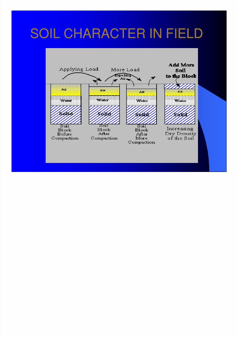
SOIL CHARACTER IN FIELDSOIL CHARACTER IN FIELD
8/7/2019 TECHNICAL NOTE FOR CONSTRUCTION
http://slidepdf.com/reader/full/technical-note-for-construction 3/44
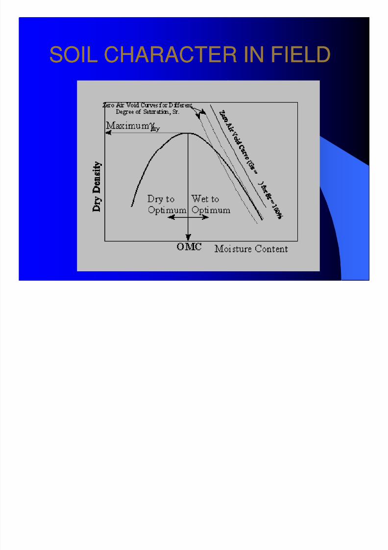
SOIL CHARACTER IN FIELDSOIL CHARACTER IN FIELD
8/7/2019 TECHNICAL NOTE FOR CONSTRUCTION
http://slidepdf.com/reader/full/technical-note-for-construction 4/44
8/7/2019 TECHNICAL NOTE FOR CONSTRUCTION
http://slidepdf.com/reader/full/technical-note-for-construction 5/44
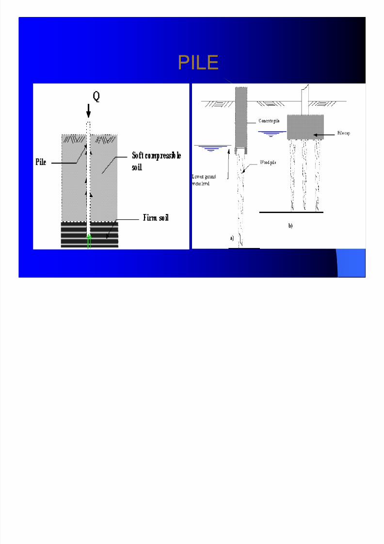
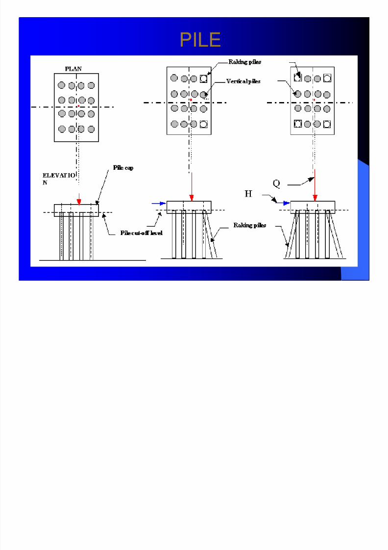
PILEPILE
8/7/2019 TECHNICAL NOTE FOR CONSTRUCTION
http://slidepdf.com/reader/full/technical-note-for-construction 6/44
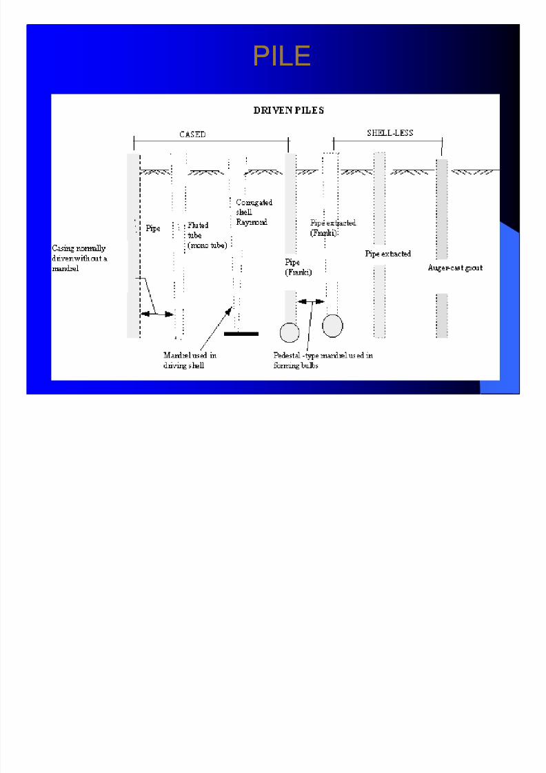
PILEPILE
8/7/2019 TECHNICAL NOTE FOR CONSTRUCTION
http://slidepdf.com/reader/full/technical-note-for-construction 7/44
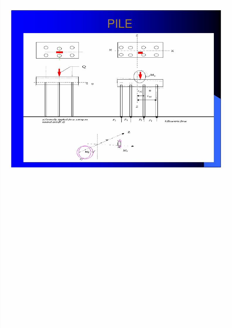
PILEPILE
8/7/2019 TECHNICAL NOTE FOR CONSTRUCTION
http://slidepdf.com/reader/full/technical-note-for-construction 8/44
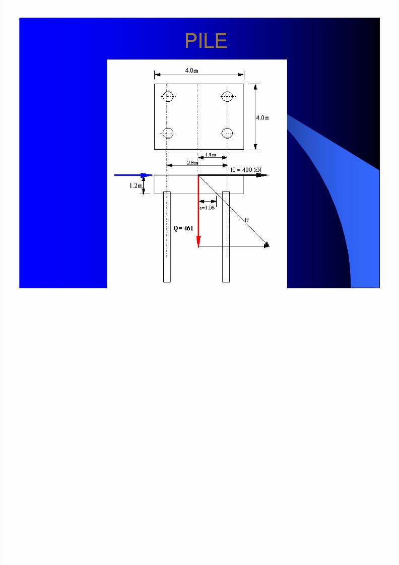
PILEPILE
8/7/2019 TECHNICAL NOTE FOR CONSTRUCTION
http://slidepdf.com/reader/full/technical-note-for-construction 9/44
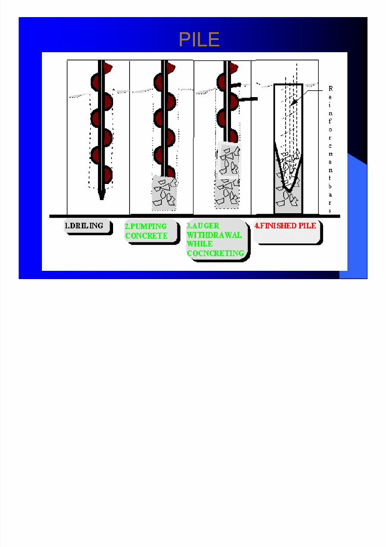
PILEPILE
8/7/2019 TECHNICAL NOTE FOR CONSTRUCTION
http://slidepdf.com/reader/full/technical-note-for-construction 10/44
PILEPILE
8/7/2019 TECHNICAL NOTE FOR CONSTRUCTION
http://slidepdf.com/reader/full/technical-note-for-construction 11/44
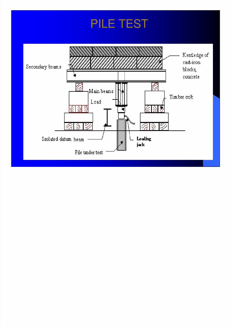
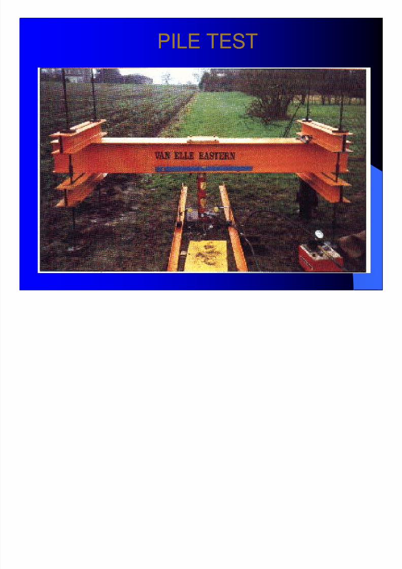
PILE TESTPILE TEST
8/7/2019 TECHNICAL NOTE FOR CONSTRUCTION
http://slidepdf.com/reader/full/technical-note-for-construction 12/44
PILE TESTPILE TEST
8/7/2019 TECHNICAL NOTE FOR CONSTRUCTION
http://slidepdf.com/reader/full/technical-note-for-construction 13/44
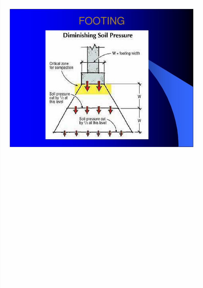
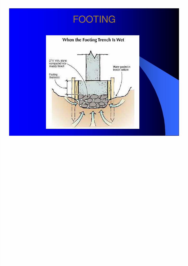
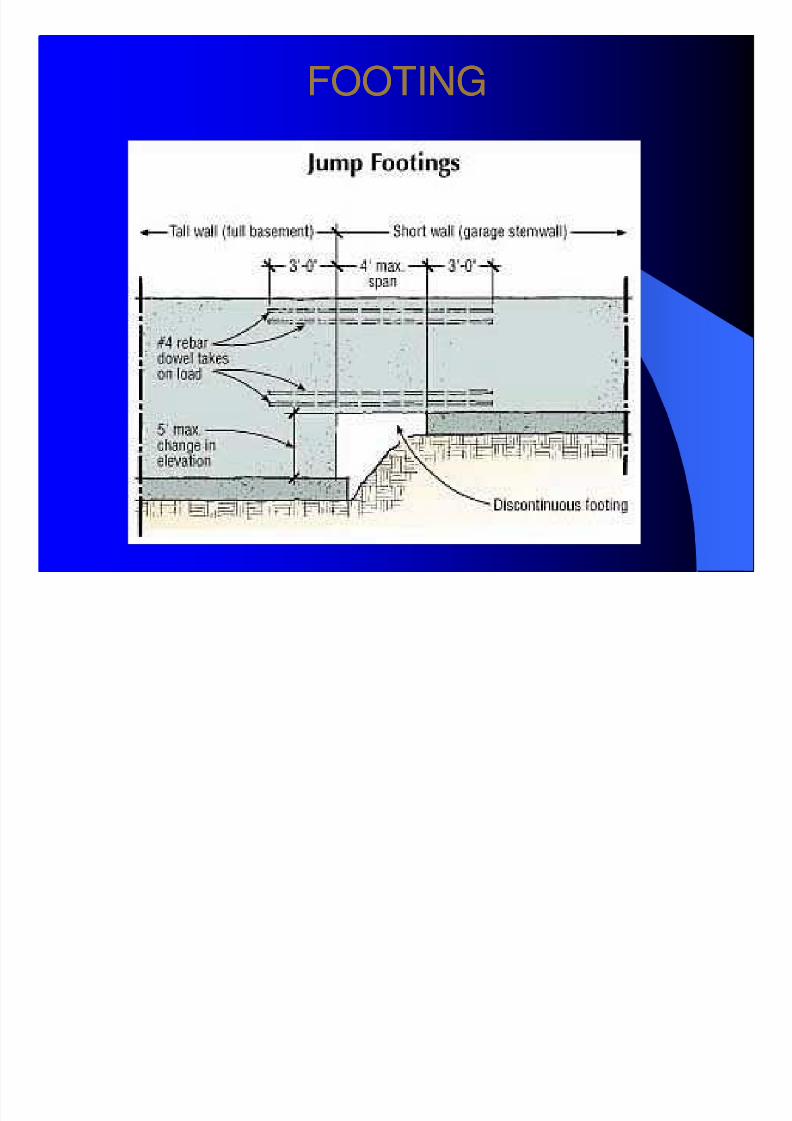
FOOTINGFOOTING
8/7/2019 TECHNICAL NOTE FOR CONSTRUCTION
http://slidepdf.com/reader/full/technical-note-for-construction 14/44
FOOTINGFOOTING
8/7/2019 TECHNICAL NOTE FOR CONSTRUCTION
http://slidepdf.com/reader/full/technical-note-for-construction 15/44
FOOTINGFOOTING
8/7/2019 TECHNICAL NOTE FOR CONSTRUCTION
http://slidepdf.com/reader/full/technical-note-for-construction 16/44
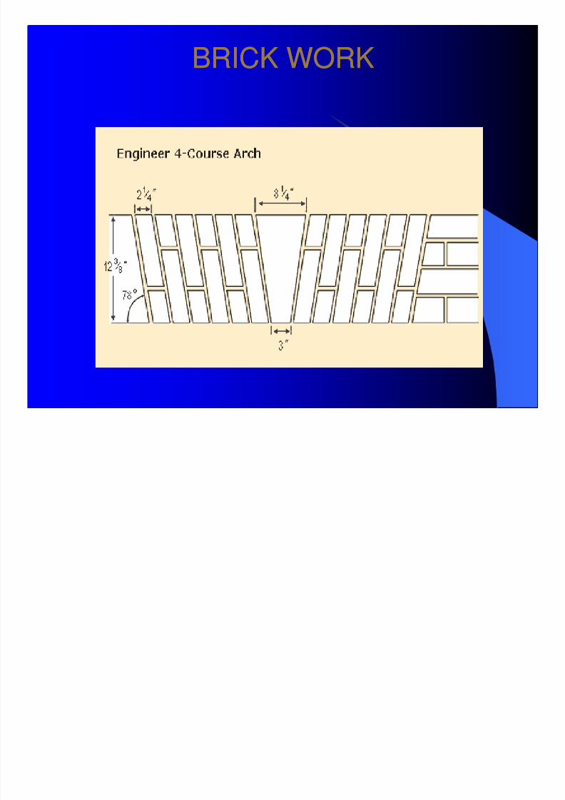
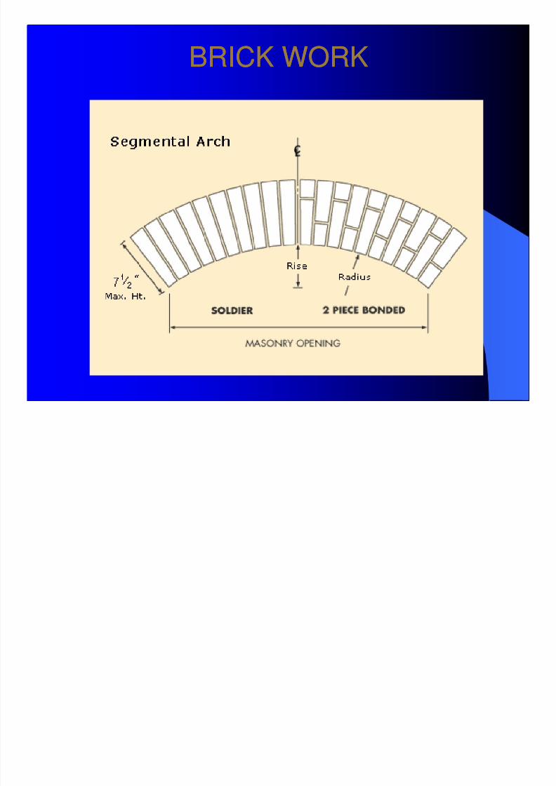
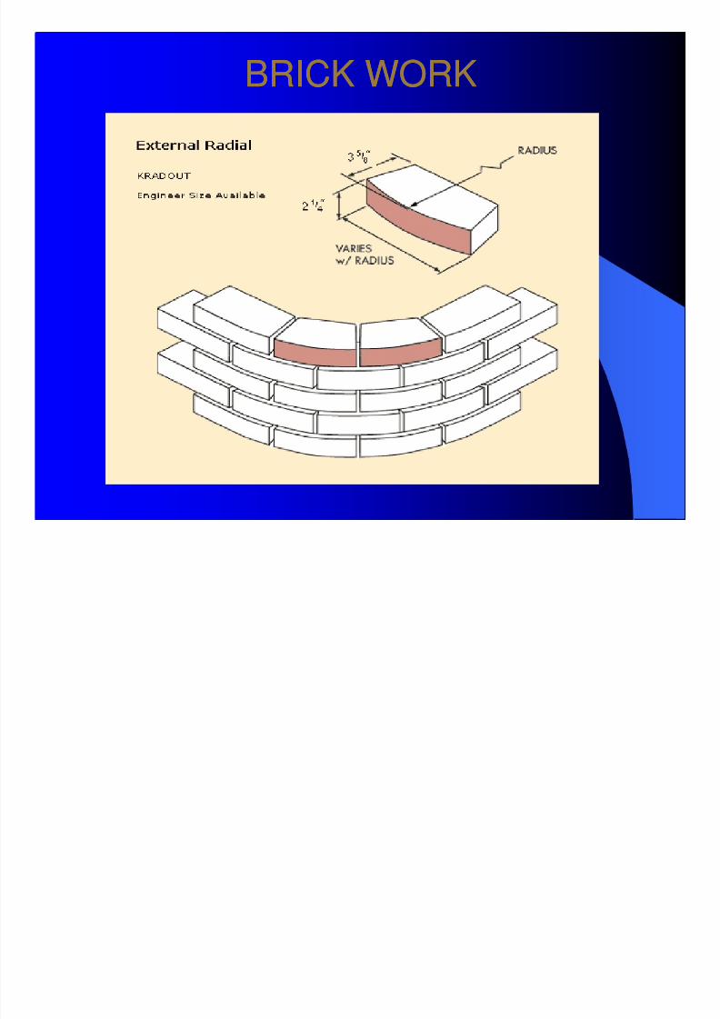
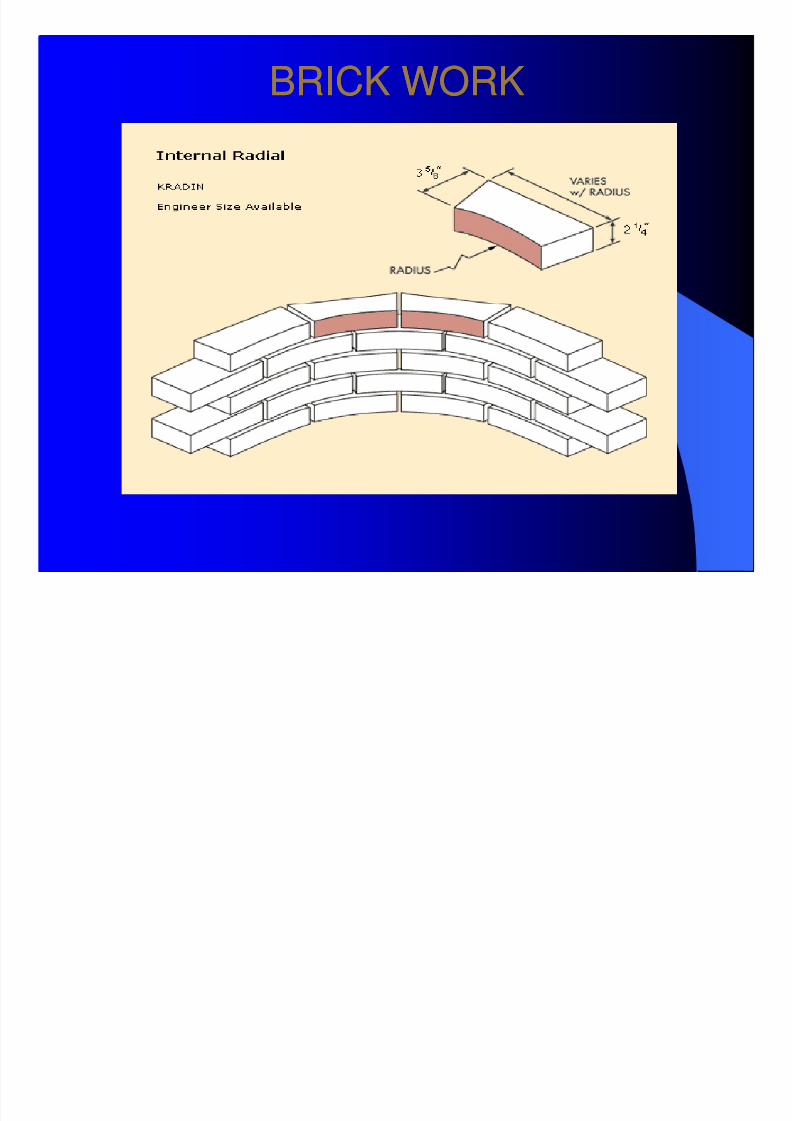
BRICK WORKBRICK WORK
8/7/2019 TECHNICAL NOTE FOR CONSTRUCTION
http://slidepdf.com/reader/full/technical-note-for-construction 17/44
BRICK WORKBRICK WORK

8/7/2019 TECHNICAL NOTE FOR CONSTRUCTION
http://slidepdf.com/reader/full/technical-note-for-construction 18/44
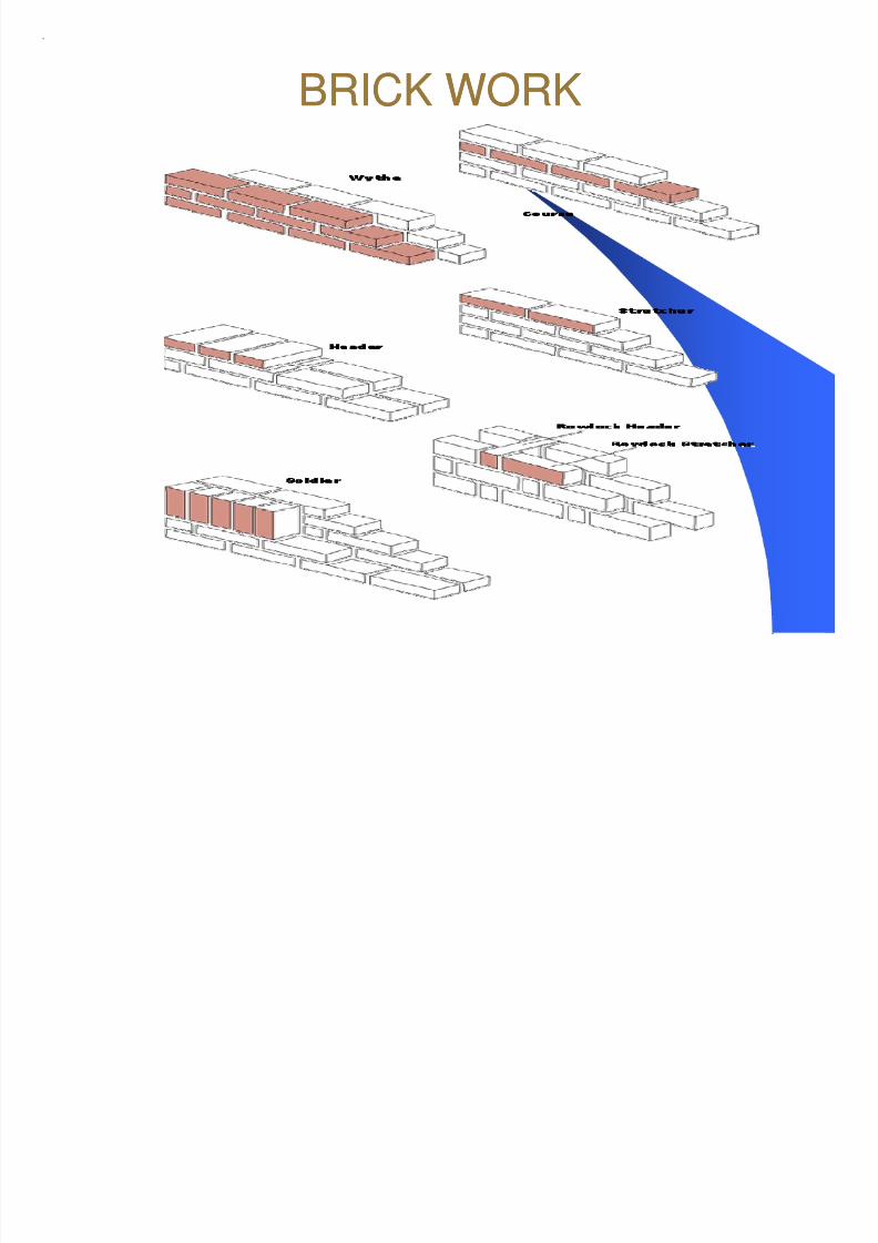
BRICK WORKBRICK WORK
8/7/2019 TECHNICAL NOTE FOR CONSTRUCTION
http://slidepdf.com/reader/full/technical-note-for-construction 19/44
BRICK WORKBRICK WORK
8/7/2019 TECHNICAL NOTE FOR CONSTRUCTION
http://slidepdf.com/reader/full/technical-note-for-construction 20/44
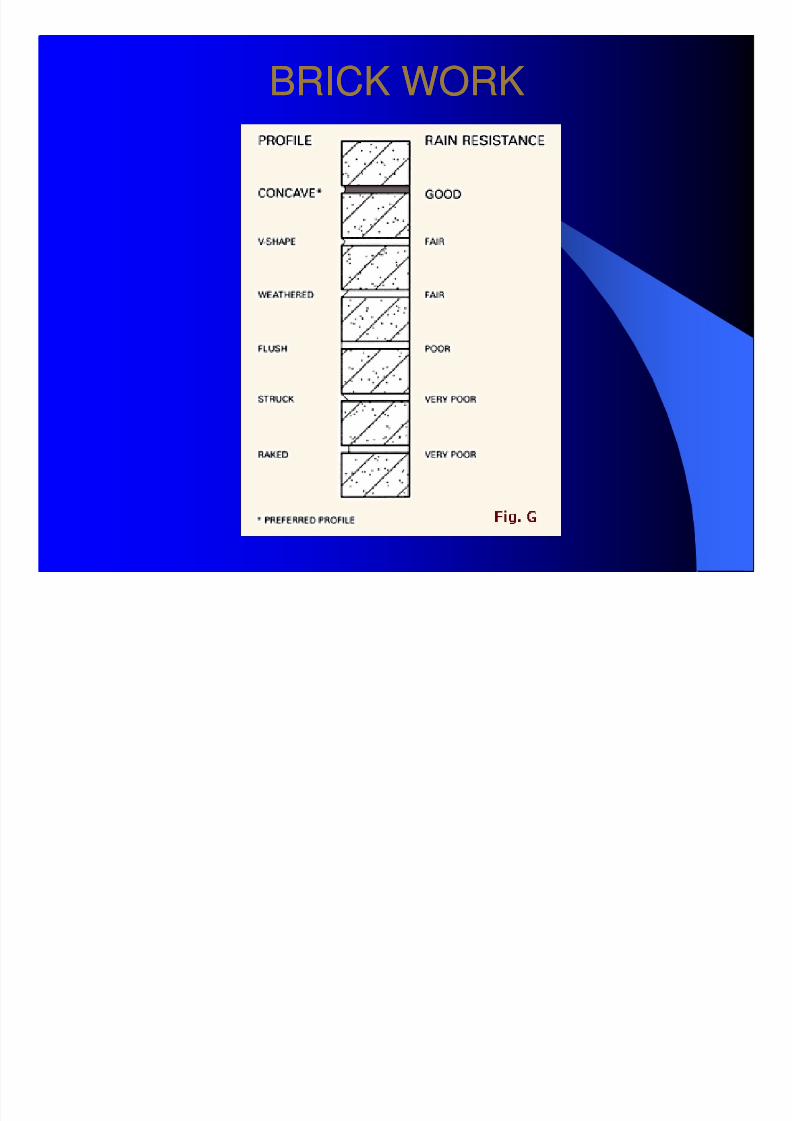
BRICK WORKBRICK WORK

8/7/2019 TECHNICAL NOTE FOR CONSTRUCTION
http://slidepdf.com/reader/full/technical-note-for-construction 21/44
BRICK WORKBRICK WORK
8/7/2019 TECHNICAL NOTE FOR CONSTRUCTION
http://slidepdf.com/reader/full/technical-note-for-construction 22/44
BRICK WORKBRICK WORK
8/7/2019 TECHNICAL NOTE FOR CONSTRUCTION
http://slidepdf.com/reader/full/technical-note-for-construction 23/44
BRICK WORKBRICK WORK
8/7/2019 TECHNICAL NOTE FOR CONSTRUCTION
http://slidepdf.com/reader/full/technical-note-for-construction 24/44
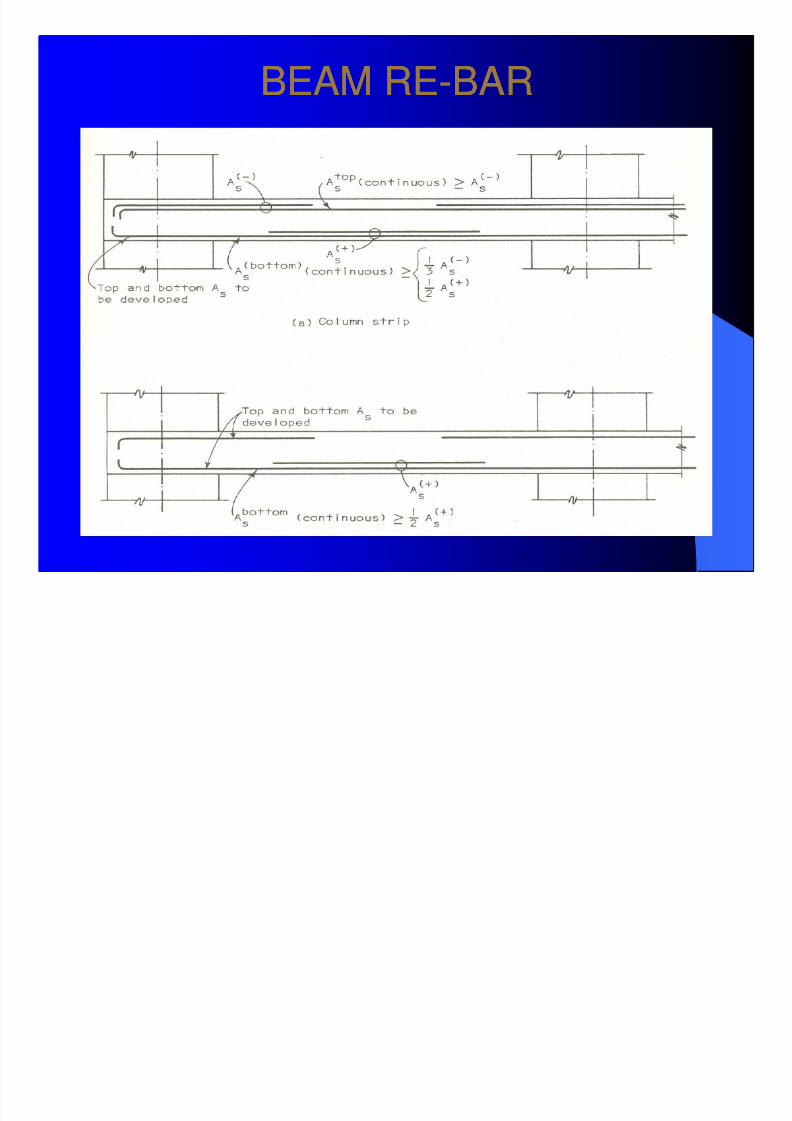
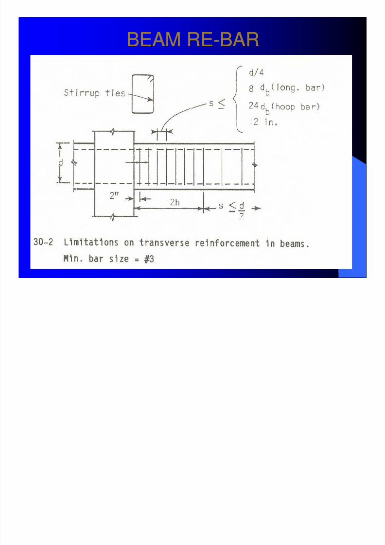
BEAM REBEAM RE--BARBAR
8/7/2019 TECHNICAL NOTE FOR CONSTRUCTION
http://slidepdf.com/reader/full/technical-note-for-construction 25/44
BEAM REBEAM RE--BARBAR
8/7/2019 TECHNICAL NOTE FOR CONSTRUCTION
http://slidepdf.com/reader/full/technical-note-for-construction 26/44
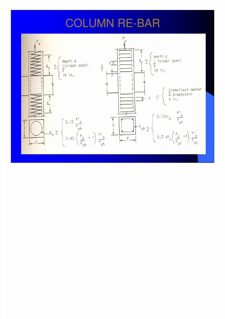
COLUMN RECOLUMN RE--BARBAR
8/7/2019 TECHNICAL NOTE FOR CONSTRUCTION
http://slidepdf.com/reader/full/technical-note-for-construction 27/44
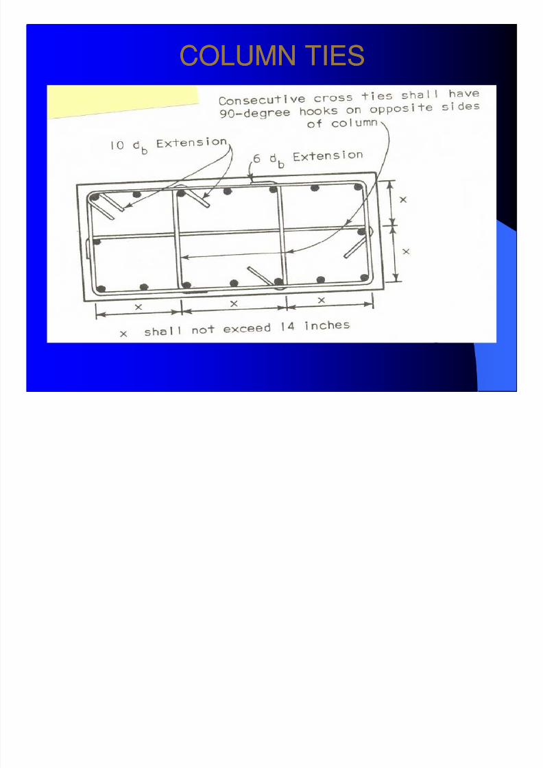
COLUMN TIESCOLUMN TIES

8/7/2019 TECHNICAL NOTE FOR CONSTRUCTION
http://slidepdf.com/reader/full/technical-note-for-construction 28/44
COLUMN RECOLUMN RE--BAR AND TIESBAR AND TIES
8/7/2019 TECHNICAL NOTE FOR CONSTRUCTION
http://slidepdf.com/reader/full/technical-note-for-construction 29/44
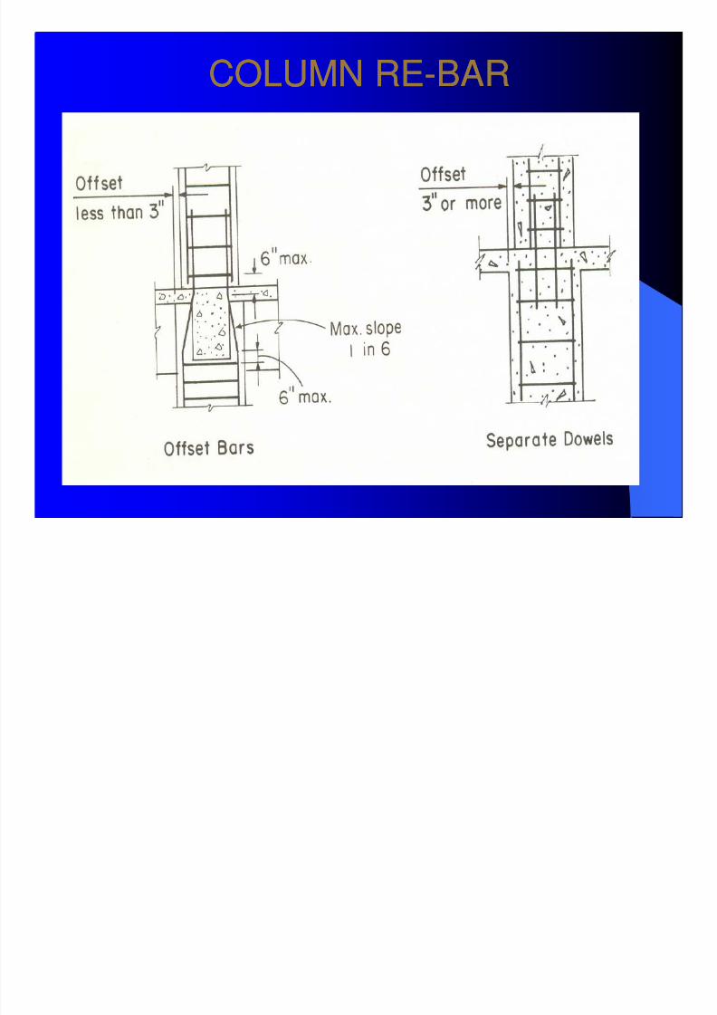
COLUMN RECOLUMN RE--BARBAR
8/7/2019 TECHNICAL NOTE FOR CONSTRUCTION
http://slidepdf.com/reader/full/technical-note-for-construction 30/44
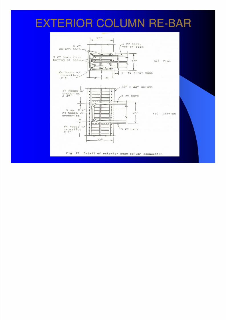
EXTERIOR COLUMN REEXTERIOR COLUMN RE--BARBAR
8/7/2019 TECHNICAL NOTE FOR CONSTRUCTION
http://slidepdf.com/reader/full/technical-note-for-construction 31/44
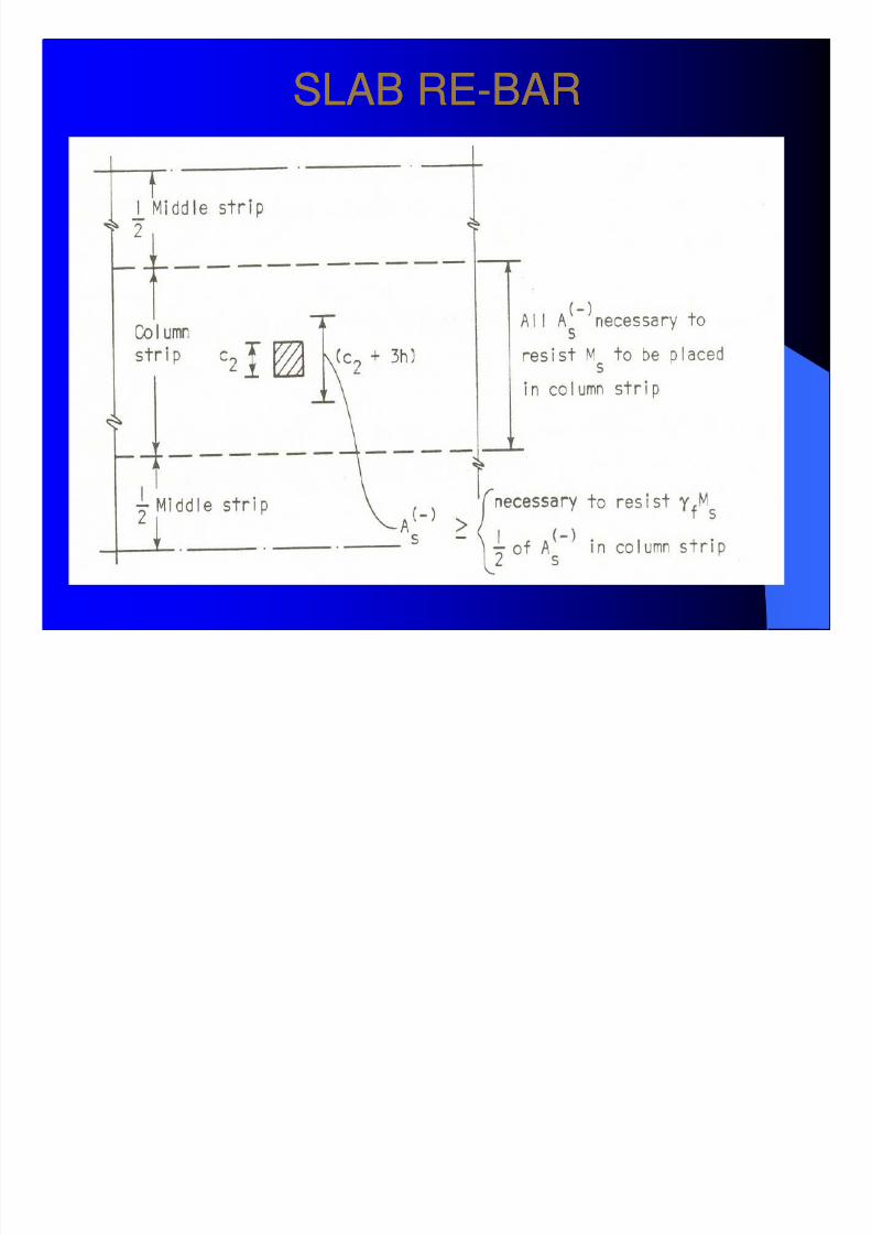
SLAB RESLAB RE--BARBAR
8/7/2019 TECHNICAL NOTE FOR CONSTRUCTION
http://slidepdf.com/reader/full/technical-note-for-construction 32/44
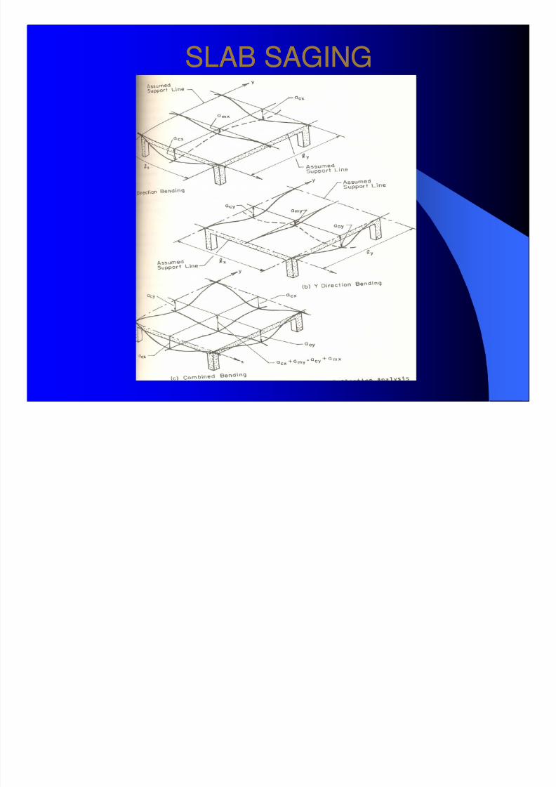
SLAB SAGINGSLAB SAGING

8/7/2019 TECHNICAL NOTE FOR CONSTRUCTION
http://slidepdf.com/reader/full/technical-note-for-construction 33/44
CONSTRUCTION PRACTICECONSTRUCTION PRACTICE
Earthquake Resistance (IS:13920Earthquake Resistance (IS:13920--1993)1993)
BeamsBeams
(i) Minimum reinforcement(i) Minimum reinforcement -- p > 0.24*sqrt (fck) / fyp > 0.24*sqrt (fck) / fy(ii) Maximum reinforcement(ii) Maximum reinforcement -- p < 0.025 orp < 0.025 or less than 2.5 %less than 2.5 %(iii) At least two bars should be provided continuously both at top and(iii) At least two bars should be provided continuously both at top andbottom.bottom.
be less than onebe less than one--half of the negative moment of resistance providedhalf of the negative moment of resistance providedat that face of the joint.at that face of the joint.(v) Neither the negative nor the positive moment of resistance at any(v) Neither the negative nor the positive moment of resistance at anysection along the member length should be less than onesection along the member length should be less than one--fourth of thefourth of the
maximum moment of resistance provided at the face of either joint.maximum moment of resistance provided at the face of either joint.(vi) When a beam frames into a column, both the top and bottom bars(vi) When a beam frames into a column, both the top and bottom barsof the beam should be anchored into the column so as to developof the beam should be anchored into the column so as to developtheir full strength in bond beyond the section of the beam at the facetheir full strength in bond beyond the section of the beam at the faceof the column, that is, the anchor length should be equal to Ld.of the column, that is, the anchor length should be equal to Ld.
8/7/2019 TECHNICAL NOTE FOR CONSTRUCTION
http://slidepdf.com/reader/full/technical-note-for-construction 34/44
CONSTRUCTION PRACTICECONSTRUCTION PRACTICE
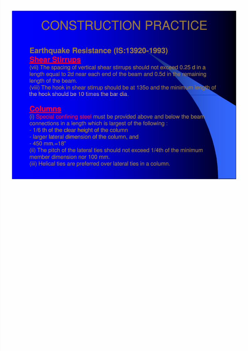
Earthquake Resistance (IS:13920Earthquake Resistance (IS:13920--1993)1993)Shear StirrupsShear Stirrups
(vii)(vii) The spacing of vertical shear stirrups should not exceed 0.25 d in aThe spacing of vertical shear stirrups should not exceed 0.25 d in alength equal to 2d near each end of the beam and 0.5d in the remaininglength equal to 2d near each end of the beam and 0.5d in the remaining
length of the beam.length of the beam.(viii) The hook in shear stirrup should be at 135o and the minimum length of(viii) The hook in shear stirrup should be at 135o and the minimum length of
..
ColumnsColumns(i)(i) Special confining steelSpecial confining steel must be provided above and below the beammust be provided above and below the beamconnections in a length which is largest of the following :connections in a length which is largest of the following :-- 1/6 th of the clear height of the column1/6 th of the clear height of the column
-- larger lateral dimension of the column, andlarger lateral dimension of the column, and-- 450 mm.=18”450 mm.=18”(ii) The pitch of the lateral ties should not exceed 1/4th of the minimum(ii) The pitch of the lateral ties should not exceed 1/4th of the minimum
member dimension nor 100 mm.member dimension nor 100 mm.(iii) Helical ties are preferred over lateral ties in a column.(iii) Helical ties are preferred over lateral ties in a column.

8/7/2019 TECHNICAL NOTE FOR CONSTRUCTION
http://slidepdf.com/reader/full/technical-note-for-construction 35/44
CONSTRUCTION PRACTICECONSTRUCTION PRACTICE
Earthquake Resistance (IS:13920Earthquake Resistance (IS:13920--1993)1993)
IN RESIDENTIAL BUILDINGSIN RESIDENTIAL BUILDINGS
In normal beams up to about 4 m span, 4 to 6 no.12 mm to 16 mm dia. highIn normal beams up to about 4 m span, 4 to 6 no.12 mm to 16 mm dia. highstrength deformed bars should normally be sufficient depending upon thestrength deformed bars should normally be sufficient depending upon the
loads.loads.In normal beamsIn normal beams up to about 4 m span, shear stirrups of 8 mm dia.up to about 4 m span, shear stirrups of 8 mm dia.-- 2 legged2 legged
mm c c s ou e su c en .mm c c s ou e su c en .
In normal slabsIn normal slabs up to about 4 m x 4 m span, 8 mm high strength deformedup to about 4 m x 4 m span, 8 mm high strength deformedbars @ 100 mm c/c should be sufficient in 100 mm thick slabs.bars @ 100 mm c/c should be sufficient in 100 mm thick slabs.
In lintelsIn lintels up to about 3 m span over doors or windows, 3up to about 3 m span over doors or windows, 3--10 mm bars should10 mm bars shouldbe sufficient.be sufficient.In sun shadesIn sun shades up to about 45 cm cantilever span, 8 mm bars @ 150 mm c/cup to about 45 cm cantilever span, 8 mm bars @ 150 mm c/c
should be sufficient. These bars must be anchored into the lintel by at least 60should be sufficient. These bars must be anchored into the lintel by at least 60cm length.cm length.In normal columnsIn normal columns, 12 mm bars should be sufficient. The exact number will, 12 mm bars should be sufficient. The exact number will
depend upon the load.depend upon the load.The following drawings illustrate some commonly encountered situations forThe following drawings illustrate some commonly encountered situations for
detailing of reinforcement.detailing of reinforcement.
8/7/2019 TECHNICAL NOTE FOR CONSTRUCTION
http://slidepdf.com/reader/full/technical-note-for-construction 36/44
CONSTRUCTION PRACTICECONSTRUCTION PRACTICE
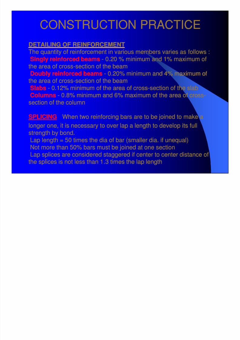
DETAILING OF REINFORCEMENTDETAILING OF REINFORCEMENTThe quantity of reinforcement in various members varies as follows :The quantity of reinforcement in various members varies as follows :Singly reinforced beamsSingly reinforced beams -- 0.20 % minimum and 1% maximum of0.20 % minimum and 1% maximum of
the area of crossthe area of cross--section of the beamsection of the beamDoubly reinforced beamsDoubly reinforced beams -- 0.20% minimum and 4% maximum of0.20% minimum and 4% maximum ofthe area of crossthe area of cross--section of the beamsection of the beamSlabsSlabs -- 0.12% minimum of the area of cross0.12% minimum of the area of cross--section of the slabsection of the slab
ColumnsColumns -- 0.8% minimum and 6% maximum of the area of cross0.8% minimum and 6% maximum of the area of cross--section of the columnsection of the column
SPLICINGSPLICING When two reinforcing bars are to be joined to make aWhen two reinforcing bars are to be joined to make a
longer one, it is necessary to over lap a length to develop its fulllonger one, it is necessary to over lap a length to develop its full
strength by bond.strength by bond.Lap length = 50 times the dia of bar (smaller dia. if unequal)Lap length = 50 times the dia of bar (smaller dia. if unequal)Not more than 50% bars must be joined at one sectionNot more than 50% bars must be joined at one sectionLap splices are considered staggered if center to center distance ofLap splices are considered staggered if center to center distance of
the splices is not less than 1.3 times the lap lengththe splices is not less than 1.3 times the lap length
8/7/2019 TECHNICAL NOTE FOR CONSTRUCTION
http://slidepdf.com/reader/full/technical-note-for-construction 37/44
CONSTRUCTION PRACTICECONSTRUCTION PRACTICE
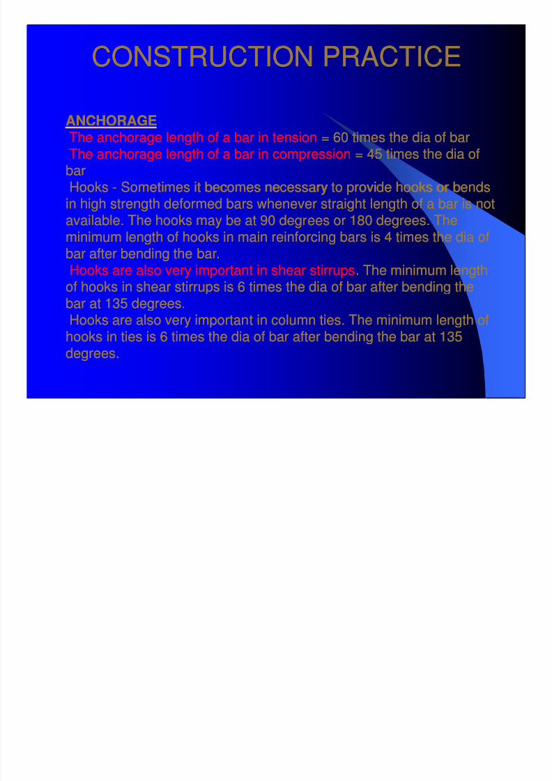
ANCHORAGEANCHORAGEThe anchorage length of a bar in tensionThe anchorage length of a bar in tension = 60 times the dia of bar= 60 times the dia of bar
The anchorage length of a bar in compressionThe anchorage length of a bar in compression = 45 times the dia of= 45 times the dia ofbarbarHooksHooks -- Sometimes it becomes necessary to provide hooks or bendsSometimes it becomes necessary to provide hooks or bendsin high strength deformed bars whenever straight length of a bar is notin high strength deformed bars whenever straight length of a bar is notavailable. The hooks may be at 90 degrees or 180 degrees. Theavailable. The hooks may be at 90 degrees or 180 degrees. Theminimum length of hooks in main reinforcing bars is 4 times the dia ofminimum length of hooks in main reinforcing bars is 4 times the dia ofbar after bending the bar.bar after bending the bar.Hooks are also very important in shear stirrupsHooks are also very important in shear stirrups. The minimum length. The minimum lengthof hooks in shear stirrups is 6 times the dia of bar after bending theof hooks in shear stirrups is 6 times the dia of bar after bending the
bar at 135 degrees.bar at 135 degrees.Hooks are also very important in column ties. The minimum length ofHooks are also very important in column ties. The minimum length ofhooks in ties is 6 times the dia of bar after bending the bar at 135hooks in ties is 6 times the dia of bar after bending the bar at 135degrees.degrees.
8/7/2019 TECHNICAL NOTE FOR CONSTRUCTION
http://slidepdf.com/reader/full/technical-note-for-construction 38/44
CONSTRUCTION PRACTICECONSTRUCTION PRACTICE
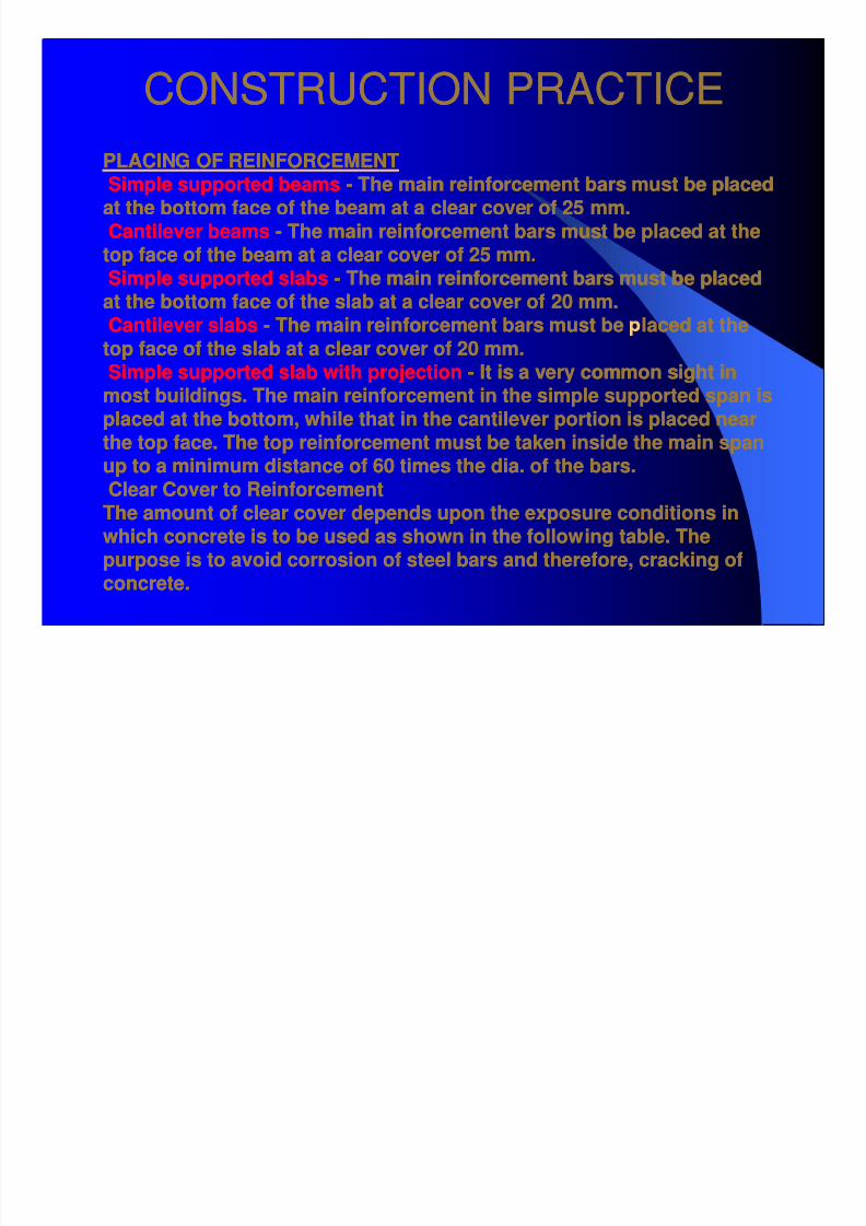
PLACING OF REINFORCEMENTPLACING OF REINFORCEMENTSimple supported beamsSimple supported beams -- The main reinforcement bars must be placedThe main reinforcement bars must be placedat the bottom face of the beam at a clear cover of 25 mm.at the bottom face of the beam at a clear cover of 25 mm.
Cantilever beamsCantilever beams -- The main reinforcement bars must be placed at theThe main reinforcement bars must be placed at thetop face of the beam at a clear cover of 25 mm.top face of the beam at a clear cover of 25 mm.Simple supported slabsSimple supported slabs -- The main reinforcement bars must be placedThe main reinforcement bars must be placedat the bottom face of the slab at a clear cover of 20 mm.at the bottom face of the slab at a clear cover of 20 mm.Cantilever slabsCantilever slabs -- The main reinforcement bars must be laced at theThe main reinforcement bars must be laced at the
top face of the slab at a clear cover of 20 mm.top face of the slab at a clear cover of 20 mm.Simple supported slab with projectionSimple supported slab with projection -- It is a very common sight inIt is a very common sight inmost buildings. The main reinforcement in the simple supported span ismost buildings. The main reinforcement in the simple supported span isplaced at the bottom, while that in the cantilever portion is placed nearplaced at the bottom, while that in the cantilever portion is placed nearthe top face. The top reinforcement must be taken inside the main spanthe top face. The top reinforcement must be taken inside the main spanup to a minimum distance of 60 times the dia. of the bars.up to a minimum distance of 60 times the dia. of the bars.
Clear Cover to ReinforcementClear Cover to ReinforcementThe amount of clear cover depends upon the exposure conditions inThe amount of clear cover depends upon the exposure conditions inwhich concrete is to be used as shown in the following table. Thewhich concrete is to be used as shown in the following table. Thepurpose is to avoid corrosion of steel bars and therefore, cracking ofpurpose is to avoid corrosion of steel bars and therefore, cracking ofconcrete.concrete.
8/7/2019 TECHNICAL NOTE FOR CONSTRUCTION
http://slidepdf.com/reader/full/technical-note-for-construction 39/44
CONSTRUCTION PRACTICECONSTRUCTION PRACTICE
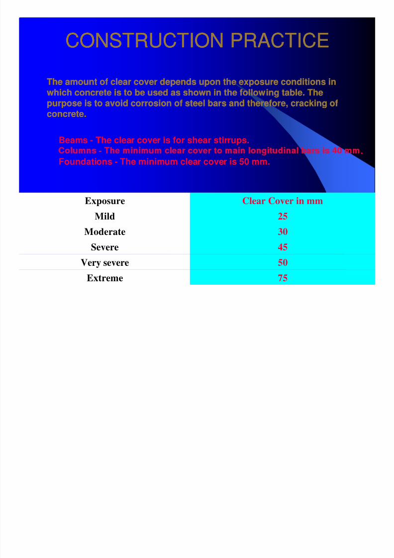
The amount of clear cover depends upon the exposure conditions inThe amount of clear cover depends upon the exposure conditions in
which concrete is to be used as shown in the following table. Thewhich concrete is to be used as shown in the following table. Thepurpose is to avoid corrosion of steel bars and therefore, cracking ofpurpose is to avoid corrosion of steel bars and therefore, cracking of
concrete.concrete.
Beams - The clear cover is for shear stirrups.
Exposure Clear Cover in mm
Mild 25Moderate 30
Severe 45
Very severe 50
Extreme 75
.
Foundations - The minimum clear cover is 50 mm.
8/7/2019 TECHNICAL NOTE FOR CONSTRUCTION
http://slidepdf.com/reader/full/technical-note-for-construction 40/44
CONSTRUCTION PRACTICECONSTRUCTION PRACTICE
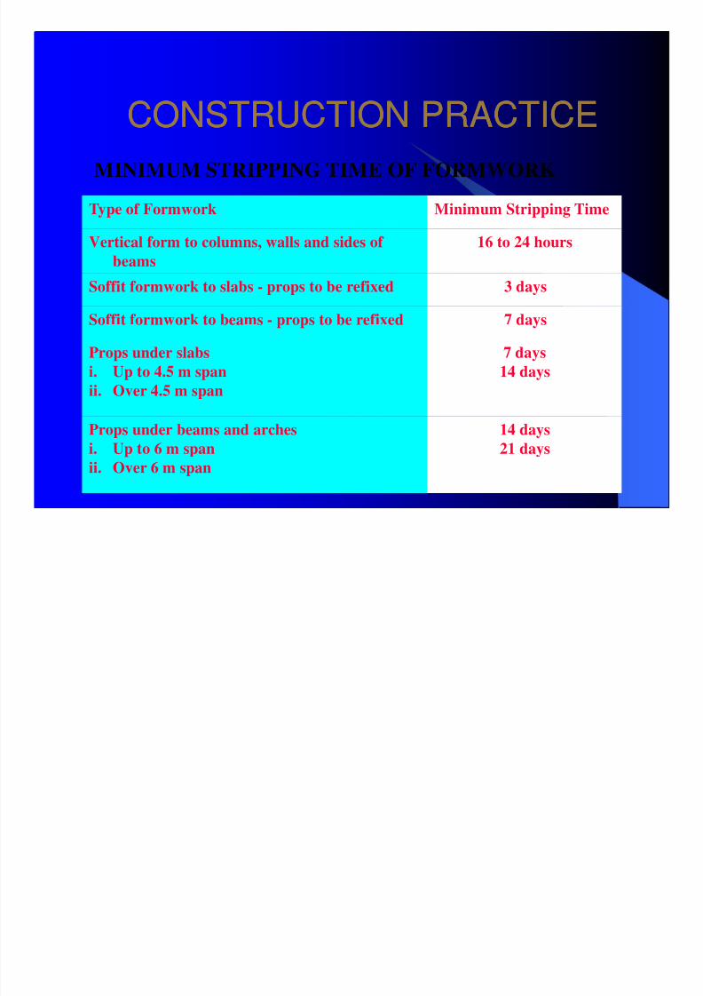
MINIMUM STRIPPING TIME OF FORMWORK
Type of Formwork Minimum Stripping Time
Vertical form to columns, walls and sides of
beams
16 to 24 hours
Soffit formwork to slabs - props to be refixed 3 days
Soffit formwork to beams - props to be refixed 7 days
Props under slabs
i. Up to 4.5 m span
ii. Over 4.5 m span
7 days
14 days
Props under beams and arches
i. Up to 6 m span
ii. Over 6 m span
14 days
21 days

8/7/2019 TECHNICAL NOTE FOR CONSTRUCTION
http://slidepdf.com/reader/full/technical-note-for-construction 41/44
CONSTRUCTION PRACTICECONSTRUCTION PRACTICE
QUALITY ASSURANCE AND QUALITY CONTROLQUALITY ASSURANCE AND QUALITY CONTROL
All architectural, structural, electrical, mechanical, and sanitaryAll architectural, structural, electrical, mechanical, and sanitarydrawingsdrawingsTest reports and manufacturer's certificates regarding allTest reports and manufacturer's certificates regarding allmaterials and equipment etc.materials and equipment etc.Records of site inspection of workmanship and various fieldRecords of site inspection of workmanship and various fieldteststestsTasks and responsibilities of all persons involvedTasks and responsibilities of all persons involvedNonNon--conformance reports and change ordersconformance reports and change ordersAcceptance criteria of concrete and dataAcceptance criteria of concrete and data
Quality control charts, andQuality control charts, andStatistical analysisStatistical analysis

8/7/2019 TECHNICAL NOTE FOR CONSTRUCTION
http://slidepdf.com/reader/full/technical-note-for-construction 42/44
CONSTRUCTION PRACTICECONSTRUCTION PRACTICE••Quality ControlQuality Control -- It has to be done by the Contractor who mustIt has to be done by the Contractor who must
ensure that the quality of materials and workmanship is as per theensure that the quality of materials and workmanship is as per thespecifications, drawings and the relevant codes of practices. This isspecifications, drawings and the relevant codes of practices. This issimilar to internal accounts audit.similar to internal accounts audit.
Quality AssuranceQuality Assurance -- It has to be done by a separate agencyIt has to be done by a separate agency
engaged by the Owner of the project. This agency has no direct input inengaged by the Owner of the project. This agency has no direct input inthe quality of work but oversees the work and assures the owner thatthe quality of work but oversees the work and assures the owner thatwork is being done as per the specifications, drawings and the relevantwork is being done as per the specifications, drawings and the relevant
codes of practices. This is similar to external accounts audit.codes of practices. This is similar to external accounts audit.
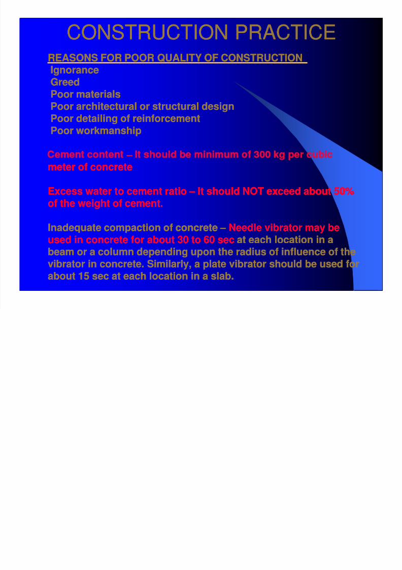
•• CAUSES OF POOR QUALITYCAUSES OF POOR QUALITY
IGNORENCEIGNORENCECARELESSNESSCARELESSNESSGREEDGREED
NEGLIGENCENEGLIGENCE
CONSTRUCTION PRACTICECONSTRUCTION PRACTICE

8/7/2019 TECHNICAL NOTE FOR CONSTRUCTION
http://slidepdf.com/reader/full/technical-note-for-construction 43/44
CONSTRUCTION PRACTICECONSTRUCTION PRACTICE
TIME MANAGEMENTTIME MANAGEMENT -- Time is MoneyTime is Money -- SAVE ITSAVE IT Plan the work forPlan the work forthe next week very carefully.the next week very carefully.
Discuss with your consultant/builder as to what materials areDiscuss with your consultant/builder as to what materials arerequired and at what stagerequired and at what stage -- CROSS CHECK AGAIN AND AGAINCROSS CHECK AGAIN AND AGAINwith the Head Mason and Suppliers.with the Head Mason and Suppliers.
Don't buy more cement than is required in the next few days.Don't buy more cement than is required in the next few days., ., .
REMEMBER the work may stop for want of a small item and theREMEMBER the work may stop for want of a small item and theentire labor may be a waste for the day.entire labor may be a waste for the day.
Shuttering, scaffolding and form work, mixer and vibrator etc.Shuttering, scaffolding and form work, mixer and vibrator etc.cost a lot in terms of rental charges. So be careful.cost a lot in terms of rental charges. So be careful.
Try to complete the Civil work as soon as possible. The woodTry to complete the Civil work as soon as possible. The woodwork, electricity, sanitary work and final finish etc. may be gotwork, electricity, sanitary work and final finish etc. may be got
done later at ease.done later at ease.
8/7/2019 TECHNICAL NOTE FOR CONSTRUCTION
http://slidepdf.com/reader/full/technical-note-for-construction 44/44