
TECHNICAL NATI@NAL ADVISCRY COMMITTEE FOR AERONAU
17
I ..T””- \.- ,,, j ... -- .. /; ;“!- ,.-.. ., .:-...,+/...”.. TECHNICAL NATI@NAL ADVISCRY COMMITTEE IMPACT OF A No. 810 SEAPLANE ON WATER WITH FOR AERONAUTICS — REFERENCE TO ELASTICITY By F, Weinig Luftfahrtforschung vol. 13, NO. 5, May,,.20~ 19rz6 Verlag von R. Oldenbourg, Munchen und Berlin . ,-- -, . . Washington November 1936 -. -. .,.. ....... . . . .... . .. . . . .. https://ntrs.nasa.gov/search.jsp?R=19930094610 2020-06-17T00:46:07+00:00Z
Transcript of TECHNICAL NATI@NAL ADVISCRY COMMITTEE FOR AERONAU
I..T””- \.-
,,, j ... --.. /; ;“!-,.-...,.:-...,+/...”..
TECHNICAL
NATI@NAL ADVISCRY COMMITTEE
IMPACT OF A
No. 810
SEAPLANE ON WATER WITH
FOR AERONAUTICS
—REFERENCE TO ELASTICITY
By F, Weinig
Luftfahrtforschungvol. 13, NO. 5, May,,.20~ 19rz6
Verlag von R. Oldenbourg, Munchen und Berlin.
,-- -, . .
WashingtonNovember 1936
-. -. .,.. .. .. . .. . . . . .. . . .. . . . ..
https://ntrs.nasa.gov/search.jsp?R=19930094610 2020-06-17T00:46:07+00:00Z
: Illlllllllllllmmiuillllllllllllllll“i31176014374087
.-..
— —
NATIONAL ADVISORY COMMITTEE FOR AERONAUTICS
TECHNICAL MEMORANDUM NO. S1O
,,
IMPACT OF A VEE-TYPE SEAPLANE ON WATER WITH
REFERENCE TO ELASTICITY*
By F. Weinig
The theory developed by H. Wagner for the computationof the landing impact on water for a rigid float is extend-ed to include elastic floats by introducing the concept ofan equivalent rigid bottom to substitute for the actualelastic bottom.
OBJECT OF INVESTIGATION
The theory developed by H. Wagner for the computationof the landing of float bottoms on the water is extendedto include bottoms having elasticity in order to take ac-count of the elasticity factor on the landing impact.
WAGNER;S THEORY OF THE IMPACT OF VEE-TYPE FLOATS
WITH RIGID BOTTOMS
Let the downward velocity of the seaplane V justbefore impact be denoted by Vo. During the immersionprocess which is assumed to “start at t=o, v = v(t).
In investigating the im~act me assume for conveniencethat the float is at rest while the water is in motionrelative to it. Essentially this flow is similar to thatof an infinite fluid about & flat plate at rest, the width2C of the plate corresponding to the instantaneous widthof the impact area of the float (fig. 1). The velocity of
*llBerucksichtigung der Elastizi”tlt beim Aufschlag einesgekielten ?i’lugzeugschwimmers auf das Was.ser.’’.,,.,Luftfahrtforschung, vol. 13, no. 5, May 20, 1936, PPO155-159.
.—— —... —
. .. .
2 N.A.C.A, Technimal Memorandum”No. 810
the water particles at the free surface (X> c) is
The rise Y of the water measured from the instant of im-mersion is
=ftvntit=ftT iit
Yo 0/=3”
The width of the impact area increases with time; i.e. ,c = c(t), so that since t = t(c), v = v(c)
c‘x
As soonedge of
We set
“(c)‘=%’ ‘=c~F$as the water particle. at position Xthe impact area, C=x and Y=Y~,
xY~=J
u(c) d-c
o
f
C21-
F
and with
reaches thesc that
Y~ f U(f) d~
“v; ‘=;=; ~=~; “of]= “)
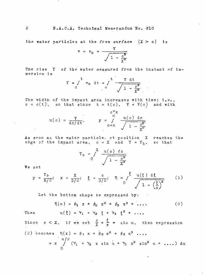
Let the bottom shape be expressed hy:
q(x) = pl x+ p2 X2+ @3 X3+’...”. (.2)
T~,en u(~) = %’~ + Y~ f + Ys f= + ..,.
Since Ccx, if we sei L=:=x sin a, then expression
(2) becomes ~(x) =plx+ ~zxa+ p3x3 . . . .
“ lT/2
=x / (Y1+Yax sin& +Y3x2sin2a +.. ..)da
o
.

I— . ,—
N. A. C.A. Technical Memorandum No.. ~10, 3
U(g) =kl j31+k2 ~2
‘where”
kl=~ = 0.636”;n.
1C3 =:X: = 1.272;
k5=? x2x 4T T = 1.696;
l-r
k7=~ x:x:x&=2.040;l-r 5
In general,
t+ks I% f+ ..... (2a)
k2=l = 1.000”
k4=:
“1
= 1.500(3)
k6 = $xz
= 1.g75
kn=—.————1
Tr/2
f~inn-l a da
o
From kn there is derived the formula
For large values of n the following approximate for-mula applies:
r .—kn - 2n-1 (n> 4)
%
while for small va,lues of n the approximate formula is
kn -r
2n - 4 +“n.— (n< 4)?-l
In some cases the bottom shape is better expressed by
l-l= ~~X+~nXn
and the value of u is then obtained as
U“ = kl ~1 + kn fln ~n-l
.—

4 N,.A. C.A. Technical Memorandum No.. 810
For nonintegral values of n the values of kn mayke read off figure 2.
In order to determine the force P exerted on thefloat, we again consider the surface of the water to be atrest and the float moving relatively to it with velocityv = v(t). The momentum of the fluid at the lower halfplane is known to be
from which,dc V
substituting ~~.;,, we obtain
(4)
(5)
The momentum of the se~.plane of mass m is equal tom (V. - V) and for the case we are here considering wherethe elasticity, for example, of the landing ge?.r and floatbottom is neglected, this is equal t’o the momentum impart-ed to the fluid. With
UP ()B=F
M=—2m- (6)
and
V=vol+w~2
(.7)
(8)
From expression (8) it may he seen that v(f) does notdepend on the bottom shape.but only on the width of thewetted surface and on the mass. If the work of deformat-ion is neglected then
dVP=- ‘=
and me thus obtain
(9)
(lo)
For briefness, we set

—
N.A.C.A. Technical Memorandum No. g10 5
Bvoa =pl;~P~P“.~—=PI –
(11),,so that “ .
B= f (12)—(1 + ~ f~)3u(~)
The pressure dist~ibution cn the float bottom will nowhe determined. For X<C2 the velocity potential is:
cP’- TJ/-–– . -d=wThe fluid pressure p is, in g~neral,
[
aw++~ +F(t)P=-PTi 2
1
In the case me are consid.erin,g F(t) is constantsince there is nn superposition of external variable press-ures. On the surface of the water F(t) =- pL/~” If p
is the pressure above the air pressure pL then
We have
[8P=- Pl~ + * VX2
1 1L -1
acJ‘X = - ax
so that
p_v2——— _
p u jfi-~
The last term of the above equation does not apply to theedge of the impact area and is small compared to the firstt170 terms.
With the aid of (8), (9), and (10), we obtain:
.’ P1,P=.—–
“n;k
This formula does not give correct values
U(1+WE2)—
1
-- (14)
“(L)2’
2 -1x
for the edge of.
— —
6 N.A.C.A. Technical Memorandum No~”.t710
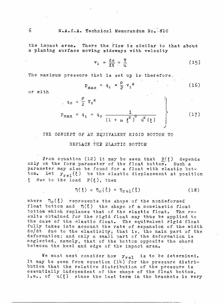
the imuact area. There the flow is similar to that about
a Planing surface moving sideways with velocity
dc_Vvl = —. -dtu
(15)
The maximum pressure that is set up is therefore,
P
p.,,
max =q1=~v12 (16)or with
P = q~ = q~1
max 2(l+vf2) u2(g)
1
ITHE CONCEPT OF “AN EQUIVALENT RIGID BOTTOM TO
REPLACE THE ELASTIC BOTTOM
(17)
From equation (12) it may be seen that g(~) dependsonly on the form parameter of the float bottom. Such aparameter may also be found for a float with elastic bot-tom. Let Yrel(t) he the elastic displacement at position
~ due to the load P(~), then
where To(f) represents the shape of the nondeformedfloat bottom and ~(~) the shape of a nonelastic floatbottom which replaces that of the elastic float. The re-sults obtained for the rigid float may thus be applied tothe case of the elastic float. The equivalent rigid floatfully takes into account the rate of expansion of the widthdc/dt due to the elasticity; that is, the main part of thedeformation; and only a small part of the deformation isneglected, namely, that of the bottom opposite the chordbetween t,he keel and edge of the impact area.
We must next consider how Yrel is to he determined.
It may be seen from equation (14) for the pressure distri-bution that the relative distribution of the pressure isessentially independent of the shape of the float bottom,i.e., of u(~) since the last term in the brackets is very

— -—
N.A.C.A. Technical Memorandum No. “g10 7
small compared. to the other terms for the greatest part of’
the range o<x<~. .,,
If the elastic deformation for the same relative pres-sure distribution is proportional to the total load, thenthe deformation under the load ~(~) at any position ~may be expressed in the form
Trel(E) =2(5) (ao+al f+a2 !.2+a3 f3+ . ...) (19).“
or with 5=X.
‘Trel(x) ‘~(x) (a. + al x+ a2 X2 +a3 X3 + . ...)
For liriefness we shall denote the ex-oression in parenthe-ses which takes account of the elasticity by A(E):
The coefficients a. , al, aa , a3 must be determined,
for each type of float, either by experiment or computa-tion. The pressure distributions given by equation (14),which applies to rigid floats, are to be substituted andthus the bending at the edge of the impact area determined’.
We have assumed that the elastic deformation was pro-portional to the load P, but due to the small thicknessof the float bottom this assumption will in many cases notgrove to be correct. In these cases, however, it may betaken as a first approximation that for a moderate in-crease in an assumed loading the increase in the deforma-tion is proportional to the load increase.
In order to determine the deformation it may be as-sumed first that the load is the same as that exerted onthe nondeformed float on impact, the corresponding defor-mation under this load determined, and then the deforma-tion when the load is slightly increased. In this way anexpression for the deformation may be found of the forh
Vrel(x) = Vorel(x) + ~(ao + al x + a2 X2 + •~00)
~0 + ‘QOrel = fio = 11 x + & “X2 + F3 X3 + .,*,
,and the same formulas apply for the determination of the
‘.=. —

I
8 N.A.C.A. Technical Memorandum No. g10
impact force as for the case where the deformation wastake~ proportional to the load, provided we replace pi
This method of computation is admissible provided theequation for Yrel gives sufficiently accurate values
corresponding to the load P first obtained; otherwise,the computation must be repeated for a new value of P.
PROCESS FOR OBTAINING THE EQUIVALENT I?LOAT BOTTOM AND
DETERMINING THE EFFECT OF THE ELASTICITY
ON TdE IMPACT FORCE
a) Mathematical formulation of the problem as an in-.—— —.—tegral equation.- Ifehave given
—.—~P , A(~)” and seek
to determine Trel* From equations (12) and (19)
‘Qrel = ‘—t A(f) .(20)
(1 + V 52)3 (Uo(f) + urel( f))
“and therefore,
and from equations (1) and. (18)
so that for the d.etermination of ~rel, we obtain the
following relation:
t A(t) 1‘flO(x) = - ‘nre~ (x ) + fx-——-—-—”— __
d~ (21),_—-
0 (l+W 52)3/1 - (+)2 ‘rel(f)
This is a nonhomogeneous, nonlinear integral (Volterra)
equation of the second class. No direct methods have so
far been developed for the solution of equations of this
—
N.A.C.A. Technical Memorandum No. g10 9
kind. In the case, however, where there exists a solution
u(~) = o“ the iteration method may probably lead to thesolution.
b) Development into series and approximate solutions.-Instead of carrying out the iteration process a solutionwas first attempted by development into series and thefollowing series were-tried:
A, IT =po + pl ~ + pa 52 + ....
B. l-r(1+ lJf2)3 =p I + p I g + p2J ~: + ...0 1
c* llre~=PI’ x+ P2’x2+P3 ‘X3+...
These expressions may be simplified, depending on the typeof float, by the elimination, for example, of the firstterm of the series. None of these series, hovev,er, con-verges in general (corresponding to the nonconverging of
the series in the development of ~~~ = 1 - x + X2 - X3+ -
..* for x > 1).
It was then attempted. to find approximate solutionsbut it was not possible to obtain good approximations sincethe system of equations to be solved was no longer linearso that this method, too, W.aS unsatisfactory.
The possibility of using the iteration method was nottried since it could only be applied to individual casesin connection with a granhical process, and the resultsthus obtained would then-have no general significance.
C) Obtaining solutions by applying the inverse proc-.——.—.. _ _ess.- ‘To obtain results of more general application, the
——
~erse process may be employed; that is, we start outwith the deformed bottom shape and seek to find the origi-nal undeformed shape.
We thus have as given ‘0 = V. + l-lre~ and the function
A(E), and we obtain in turn p, Vrel, and TIO:
As an example, we choose the values

1, I I II 1111111 1111lnnlmnm-pn I I ■ nnllllnlmulllnmlmmlnllI I III II II mmmm III ■ mlmnmm mmm I 1111 mm I III I I nun I I- I ■■ m I I mm, 1 11 111,
10 N.A.C.A. .Technical Memorandum No. g10
. .
(23)
which represent a straight V bottom flcat of a seaplanehaving a very large mass. We thus obtain:
. mQ=B~x- + Cp g(x) .—Trl,.
or with
U. =
. .
B=—
~. =
_L–kl $1
so that
3T—=lB
-$(klao+lz2al ~+kz m2 52)—0
and at f=l, where the maximum impact force is to be ex-
— I

N. A. C.A. Technical Memorandum No: g10 11
petted,,,
%el = B_(1). .
— g7T -1= -~(kluo+kaal+k~as +.. .)B—o
The deformation is:
and attains its maximum value for
_#-_-[R(g) + ~ g’(f)] = o
From the above equation
and therefore
or
and thus (for ~<1)
For ~>1 the greatest deformation is at ~=1,
so that
or
-.

12 N.A.C.A. Technical Memorandum No. 81C
and therefore,
As a first example (fig. %a), let the following val-
ues be chosen:
and
so that
~=~(1-g) (CLO=O, CL1=l, CL2=-1)
In this case the bcttom (construction A) is deformed be-tween the keel and the chine in such a manner that for aconstant impact force ~rel would be a parabola.
The maximum deformation is at
so that
~rel _ 27 firel._. __(4-Tr)m= Trel
2,gg —%—o
~(l)
The relative increase in the impact force in this caseis the~efore 2.g9 times the ratio of the maximum deformat-
ion Vrel to the dead rise q(l).
As a second example (fig. xb), let the following val-
ues be chosen:
and
so that
tR=a (a. = o, al = o, U2 = 1)—

N.A.C.A. Technical Memorandum No. g10 13
In this case (construction %b), the bottom is elasticat the sides so that the chine moves up on impacts Theform of the .A function is then obtained by assuming arigid bottom with the impact force approximately concen-trated near the edge of the impact area.
The maximum deformation is now at X=17 so that
grel - ~ ~rel(l)— =B—0 Ii(l)
This construction therefore leads to a decrease inthe impact force, namely, by twice the ratio of the defor-mation at the edge to the final dead rise Ii(l).
For the third example (fig. 3c), let the values chosenbe:
T=BIX
and A =Q(l- 52)
so that
R=l- g2(aQ=l, a,=o, m2=- 1)
(construction C).
sc that
~rel _ 3 ~rel— — = 2.6 ‘~go –“mm2
In this case, therefore, the relative increase in theimpact force is 2.6 times the ratio of the maximum defor-mation to the dead rise.
From these examples it may be deduced that under cer-tain conditions the effect of the elasticity of the bottommay be o,f some importance but in especially unfavorable
.

>,. .
14 N.A.C.A. Technical Memorandum No. g10
cases the effect may even be more considerable, so that noconclusions of general application can be attached to theresults obtained from the examples just given.
SUMivlARY
For several particular cases of possible float-bottomshapes the impact force due to the elasticity deformationwas compared with that obtained for the rigid bottom. Thework carried out considers, however, only part of the ef-fect of the elasticity on landing and obviously the lessimportant part. A much more important effect is that ofthe elastic connection between the principal masses of theseaplane and ‘the floats, and this problem still avaits so-lution.
Translation by S. Reiss,National Advisory Committeefor Aeronautics.
I

—— --—
N.A.C.A. Technical Memorandum No. 810 Figs. 1,2,3
Figure
C,E—. —.— -t———~x,x
~ = B/2C = B/2
1 .- Notation for rigid V-type float bottom landing onwater.
I
Q
v
2.0II -... ‘ ,-- IV
(a) 1~1’1.6
1*V1.2
kn
v
II \ ~ ~ IV
.8 (b) 111
.4 I _+__ v
~1II , ! , IV
o0 2 4 6 8 (c) III
n Figure 3.- Several types of
Figure 2.- Values of kn.possible deforma-
tion for float bottoms.
(a) Points I,II,III,IV, andVare mutually fixed and
bottom is deformed between II-III and III-IV.(b) Points I,IIJ andV are mutually fixed and bottom is deformed atII and IV. (c) Points I,II,IV and V are mutually fixed and deformationis possible at the keel III.
1. —..

‘llllllllllllllllMtifllMfllllllllllllllll~~~31176014374087 ,!
., ,...~
.,