Technical Manual V1.4 - Tennis Australia · PDF file• Tennis Australia for their overall...
140
TECHNICAL MANUAL For the Design, Construction and Maintenance of Tennis Facilities Compiled by the Tennis Queensland Technical Services Advisory Group
Transcript of Technical Manual V1.4 - Tennis Australia · PDF file• Tennis Australia for their overall...
TECHNICAL MANUALFor the Design, Construction and Maintenance of Tennis Facilities
Compiled by the Tennis Queensland Technical Services Advisory Group
Technical Manual
TECHNICAL MANUAL
For the Design. Construction and Maintenance of Tennis Facilities
Compiled by
Tennis Queensland’s Technical Services Advisory Group
Published by
Tennis Queensland
Second Edition – June 2008
© Tennis Queensland, 2008. All rights reserved.
No part of this publication may be reproduced in any form, by Photostat, microfilm, xerography, or any other means, or incorporated into any information retrieval system, electronic or mechanical,
without the written permission of the copyright owner.
All correspondence concerning this publication should be addressed to:-
The Technical Services Advisory Group
c/- Tennis Queensland
PO Box 2366
Graceville, QLD, 4075
Australia
Printed by Tennis Queensland, Brisbane, Australia
Technical Manual
ACKNOWLEDGEMENTS
First and foremost, the Tennis Queensland would like to thank the Queensland Government Department of Local Government, Planning, Sport & Recreation for their assistance and support. Without their financial contribution towards this project, the completion of this manual would remain an unrealised dream.
The Tennis Queensland Technical Services Advisory Group wishes to thank all organisations and individuals who have contributed information, diagrams, photographs, opinions and suggestions for incorporation into this publication. Specific mentions should be made of the following organisations and individuals who have made particularly significant contributions:
• Tennis Australia for their overall support of our ambitious project and sharing their visions for the future of tennis in Australia
• The USTA for allowing us to reproduce a number of diagrams from their own publication “Tennis Courts – A Construction and Maintenance Manual” and convert them into metric measurements for use in Australian circumstances
• William Loud (Aust) Pty Ltd and Rebound Ace Sports Pty Ltd for their contributions in relation to asphalt court construction and acrylic / cushioned acrylic court surfacing
• Both Jordin Sports and Rebound Ace Sports Pty Ltd for providing large galleries of photographs showing a wide variety of tennis courts under construction or recently completed to compliment our text and to assist the reader to visualise important information and concepts
• RAW Courts for providing information in relation to the construction and maintenance of natural clay courts and photographs of numerous pieces of equipment used to maintain of these courts and also synthetic grass tennis courts
• En Tout Cas for information relating their clay court surfacing products
• Peter Cronin for his expert input into the construction and maintenance of natural grass tennis courts (based on his skills in preparing grass tennis courts for major events, such as Australia’s Davis Cup home tie against Russia in Brisbane in 1999)
Finally, the many hours of editing reviews undertaken by Alfred Edwards (a retired BBC and ABC journalist with a number of commercial editorial credits to his name) is also greatly appreciated by the members of the Technical Services Advisory Group.
Additional thanks is also passed onto all the members of the general public who provided invaluable feedback to the initial draft version of this document that was placed on Tennis Queensland’s web site for comment and review in December 2006. Special mention in this regard is given to Mr Tim McSweeney, and Engineer from Central Queensland University, whose extremely detailed review was way beyond the level of feedback we ever anticipated from a this exercise.
The Tennis Queensland Technical Services Advisory Group members (past and present) responsible for the preparation of this first edition of this Manual were:
Bruce Lynch (Chairman), Ashley Cooper, Maurice Philp, John Chivers, Paul Bull, Ross Jordin, Colin Greeves, Michael Blomer and Cherie Murphy.
Technical Manual 1
INDEX 1 Introduction.................................................................................................................................. 7
1.1 How to use this manual........................................................................................................ 7 1.2 Purpose of the manual......................................................................................................... 7 1.3 Information sources, Standards and Codes. ....................................................................... 7 1.4 Where to get further help ..................................................................................................... 7
2 Facility planning and development.............................................................................................. 8 2.1 Definitions used in this section ............................................................................................ 8 2.2 Background.......................................................................................................................... 9 2.3 Planning ............................................................................................................................... 9 2.4 Choosing a site .................................................................................................................. 10 2.5 Budgeting........................................................................................................................... 11 2.6 Court construction on a “greenfield” site............................................................................ 12
2.6.1 Asphalt base – acrylic surface.................................................................................... 13 2.6.2 Concrete base ............................................................................................................ 16 2.6.3 Lighting ....................................................................................................................... 16 2.6.4 Landscaping ............................................................................................................... 17
3 Facilities development planning................................................................................................ 18 3.1 Introduction ........................................................................................................................ 18 3.2 Definitions used in this section .......................................................................................... 18 3.3 Project Management.......................................................................................................... 18 3.4 Funding .............................................................................................................................. 19 3.5 Ongoing costs .................................................................................................................... 19 3.6 Information sources, Standards and Codes. ..................................................................... 19
4 General site and construction consideration............................................................................. 20 4.1 Introduction ........................................................................................................................ 20 4.2 Definitions used in this section .......................................................................................... 20 4.3 Choice of site ..................................................................................................................... 20 4.4 High risk sites..................................................................................................................... 21
4.4.1 Slip areas.................................................................................................................... 21 4.4.2 Uncontrolled fill and other issues................................................................................ 21 4.4.3 Future growth.............................................................................................................. 21
4.5 Court planning.................................................................................................................... 21 4.5.1 Court dimensions........................................................................................................ 21 4.5.2 Court separation ......................................................................................................... 23 4.5.3 Dividing fences ........................................................................................................... 28 4.5.4 Orientation .................................................................................................................. 28
4.6 Vegetation.......................................................................................................................... 29 4.7 Overland flow of water and drainage................................................................................. 29
4.7.1 Surface water.............................................................................................................. 29
Technical Manual 2
4.7.2 Subsurface water........................................................................................................ 29 4.8 Choice of contractor........................................................................................................... 30
5 Earthworks and subgrade ......................................................................................................... 31 5.1 Introduction ........................................................................................................................ 31 5.2 Definitions used in this section .......................................................................................... 31 5.3 Site investigation................................................................................................................ 32 5.4 Soil report........................................................................................................................... 32 5.5 Underground flow of water and drainage........................................................................... 32 5.6 Compaction........................................................................................................................ 32 5.7 Retaining............................................................................................................................ 33
5.7.1 Types of walls ............................................................................................................. 33 5.8 Site maintenance ............................................................................................................... 38
5.8.1 Control of vegetation................................................................................................... 38 6 Base construction...................................................................................................................... 39
6.1 Introduction ........................................................................................................................ 39 6.2 Definitions used in this section .......................................................................................... 39 6.3 Choice of base to suit site conditions, surface choice ....................................................... 41 6.4 Elements common to all bases.......................................................................................... 41 6.5 Asphalt bases .................................................................................................................... 41
6.5.1 Elements of an asphalt base ...................................................................................... 41 6.5.2 Construction process.................................................................................................. 42 6.5.3 Construction failures. .................................................................................................. 43 6.5.4 Deterioration failures................................................................................................... 44 6.5.5 Measures of quality..................................................................................................... 44
6.6 Concrete bases.................................................................................................................. 44 6.6.1 Types of concrete bases ............................................................................................ 44 6.6.2 Reinforced concrete bases......................................................................................... 45 6.6.3 Construction................................................................................................................ 46 6.6.4 Post Stressed concrete bases.................................................................................... 48
6.7 Compacted earth base....................................................................................................... 50 6.8 Proprietary base systems .................................................................................................. 51
6.8.1 Chemically bound systems......................................................................................... 51 6.9 Maintenance and repair of base structure ......................................................................... 51 6.10 Information sources, Standards and Codes................................................................... 51
7 Surface ...................................................................................................................................... 52 7.1 Introduction ........................................................................................................................ 52
7.1.1 Definitions used in this section ................................................................................... 52 7.1.2 Classification of surface systems ............................................................................... 52 7.1.3 Choice of surface........................................................................................................ 52 7.1.4 Advantages and disadvantages ................................................................................. 53
Technical Manual 3
7.1.5 Maintenance issues.................................................................................................... 53 7.1.6 Playing characteristics................................................................................................ 56
7.2 Acrylic................................................................................................................................. 57 7.2.1 Acrylic hardcourts - types of systems......................................................................... 57 7.2.2 Acrylic Application....................................................................................................... 58 7.2.3 Some dos and don’ts when coating acrylic tennis courts........................................... 62 7.2.4 Cushion Acrylic ........................................................................................................... 66 7.2.5 Choice of colours for acrylic surfaces......................................................................... 69 7.2.6 Maintenance and repair of acrylic surfaces................................................................ 69 7.2.7 Resurfacing................................................................................................................. 69
7.3 Synthetic grass .................................................................................................................. 71 7.3.1 Definitions used in this section ................................................................................... 71 7.3.2 What is Sand Filled Artificial Grass (SFAG)? ............................................................. 71 7.3.3 Player preferences...................................................................................................... 73 7.3.4 Selecting a synthetic grass product............................................................................ 73 7.3.5 Mineral infill sand........................................................................................................ 75 7.3.6 SFAG installation ........................................................................................................ 76 7.3.7 SFAG maintenance .................................................................................................... 78
7.4 Synthetic Clay (outdoor carpet) surfaces........................................................................... 80 7.4.1 Introduction ................................................................................................................. 80 7.4.2 Construction................................................................................................................ 81 7.4.3 Synthetic Clay Surface ............................................................................................... 82 7.4.4 Maintenance ............................................................................................................... 82
7.5 Natural Grass Tennis Courts ............................................................................................. 83 7.5.1 Construction................................................................................................................ 83 7.5.2 Grass types................................................................................................................. 84 7.5.3 Equipment................................................................................................................... 84 7.5.4 General Maintenance ................................................................................................. 85 7.5.5 Usage ......................................................................................................................... 85 7.5.6 Preparation - social/competition ................................................................................. 85 7.5.7 Renovations................................................................................................................ 86 7.5.8 Drop in courts ............................................................................................................. 86 7.5.9 Irrigation...................................................................................................................... 86 7.5.10 Grass court maintenance ........................................................................................... 87
7.6 Compacted earth bases..................................................................................................... 89 7.6.1 European Clay ............................................................................................................ 89 7.6.2 Introduction ................................................................................................................. 89 7.6.3 Construction of a European clay court ....................................................................... 90 7.6.4 Choosing a constructor............................................................................................... 90
Technical Manual 4
7.6.5 Equipment for surface maintenance........................................................................... 90 7.6.6 General Maintenance ................................................................................................. 91 7.6.7 Using Maintenance Equipment................................................................................... 92 7.6.8 Decomposed granite................................................................................................... 94
7.7 Information sources, Standards and Codes. ..................................................................... 95 8 Fencing...................................................................................................................................... 96
8.1 Introduction ........................................................................................................................ 96 8.2 Definitions used in this section .......................................................................................... 96 8.3 Metal fencing...................................................................................................................... 97
8.3.1 Fence height ............................................................................................................... 98 8.3.2 Post installation........................................................................................................... 98 8.3.3 Post size and spacing................................................................................................. 99 8.3.4 Rails and bracing........................................................................................................ 99 8.3.5 Bracing and strainer wires ........................................................................................ 100 8.3.6 Access ...................................................................................................................... 100 8.3.7 Fence finishing.......................................................................................................... 100 8.3.8 Mesh size (diamond and wire).................................................................................. 101 8.3.9 Dividing fences. ........................................................................................................ 101 8.3.10 Draw back curtains ................................................................................................... 102
8.4 Timber fencing ................................................................................................................. 102 8.5 Attachments to fencing .................................................................................................... 102
8.5.1 Wind screens ............................................................................................................ 102 8.5.2 Sight screens ............................................................................................................ 102
8.6 Maintenance and repair of fencing .................................................................................. 103 8.7 Information sources, Standards and Codes. ................................................................... 103
9 Lighting.................................................................................................................................... 104 9.1 Introduction ...................................................................................................................... 104 9.2 Definitions used in this section ........................................................................................ 104 9.3 Types of lighting systems................................................................................................. 105
9.3.1 Lamp types. .............................................................................................................. 106 9.4 Pole configuration and heights ........................................................................................ 106 9.5 Choice of lighting systems ............................................................................................... 107
9.5.1 Colour temperature................................................................................................... 107 9.5.2 Illuminance................................................................................................................ 107 9.5.3 Uniformity.................................................................................................................. 108 9.5.4 Light Loss Factors .................................................................................................... 108 9.5.5 Glare ......................................................................................................................... 109 9.5.6 Circuit switching........................................................................................................ 109
9.6 Council regulations .......................................................................................................... 109 9.7 Maintenance of lighting.................................................................................................... 110
Technical Manual 5
9.7.1 Lamp maintenance ................................................................................................... 110 9.7.2 Luminaires ................................................................................................................ 110 9.7.3 Light towers .............................................................................................................. 110
9.8 Information sources, Standards and Codes. ................................................................... 110 9.9 Typical Suppliers.............................................................................................................. 111
10 Accessories and amenities.................................................................................................. 112 10.1 Net posts ...................................................................................................................... 112 10.2 Nets .............................................................................................................................. 113 10.3 Centre straps and anchors........................................................................................... 114 10.4 Umpires chairs ............................................................................................................. 114 10.5 Court numbers.............................................................................................................. 114 10.6 Ball machine................................................................................................................. 115 10.7 Ball retrievers ............................................................................................................... 115 10.8 Coaching baskets......................................................................................................... 115 10.9 Hit walls and rebound nets........................................................................................... 115 10.10 Other court accessories ............................................................................................... 115 10.11 Off court accessories.................................................................................................... 116 10.12 Security and safety....................................................................................................... 116 10.13 Suppliers of tennis court accessories........................................................................... 116 10.14 Information sources, Standards and Codes................................................................. 117
11 Indoor tennis, enclosures and roof structures ..................................................................... 118 11.1 Introduction................................................................................................................... 118 11.2 Court enclosures. ......................................................................................................... 118 11.3 Requirements of the rules ............................................................................................ 118
11.3.1 ITF Recommendation on ceiling heights .................................................................. 118 11.3.2 Construction Manual – USTA ................................................................................... 118 11.3.3 Guidance Notes – LTA (Britain)................................................................................ 119
11.4 Types of roof structures................................................................................................ 119 11.4.1 Rigid structures......................................................................................................... 119 11.4.2 Membrane structures................................................................................................ 119 11.4.3 Inflatable structures .................................................................................................. 119
11.5 Information sources, Standards and Codes................................................................. 120 11.5.1 Rules and guidelines ................................................................................................ 120 11.5.2 Suppliers on the Internet. ......................................................................................... 120
12 Club facilities ....................................................................................................................... 121 12.1 Introduction................................................................................................................... 121
12.1.1 Layout ....................................................................................................................... 121 12.1.2 Size requirements..................................................................................................... 121 12.1.3 Other provisions........................................................................................................ 122
12.2 Information sources, Standards and Codes................................................................. 122
Technical Manual 6
13 Managing a project .............................................................................................................. 123 13.1 Introduction................................................................................................................... 123 13.2 Definitions used in this section..................................................................................... 123 13.3 Obtaining technical guidance ....................................................................................... 123 13.4 Site investigation .......................................................................................................... 124 13.5 Preparing a technical specification............................................................................... 124 13.6 Inviting tenders from the construction industry ............................................................ 124 13.7 Choosing between tenders .......................................................................................... 126 13.8 Contracts and project acceptance................................................................................ 126 13.9 Project supervision ....................................................................................................... 127 13.10 Progress payments and retentions .............................................................................. 127 13.11 Repairs under warranty ................................................................................................ 128 13.12 Information sources, Standards and Codes................................................................. 129
14 Care and maintenance of tennis courts............................................................................... 130 14.1 General maintenance................................................................................................... 130 14.2 Hard court and cushioned hard court maintenance ..................................................... 130 14.3 Indoor acrylic surfaces ................................................................................................. 131 14.4 Hard court maintenance equipment ............................................................................. 131 14.5 Sand filled synthetic grass maintenance...................................................................... 131 14.6 Grass court maintenance ............................................................................................. 132 14.7 Clay court maintenance................................................................................................ 132 14.8 Court equipment maintenance ..................................................................................... 132
14.8.1 Installing a tennis net. ............................................................................................... 132 14.8.2 Net maintenance....................................................................................................... 132 14.8.3 Net post maintenance............................................................................................... 132
14.9 Windscreens and windscreen maintenance ................................................................ 133 14.10 Landscape maintenance .............................................................................................. 134
15 Document control ................................................................................................................ 136 15.1 Date of preparation....................................................................................................... 136 15.2 Review date.................................................................................................................. 136 15.3 Disclaimers................................................................................................................... 136
16 APPENDICES ..................................................................................................................... 137
Technical Manual 7
1 Introduction
1.1 How to use this manual This manual has been prepared by the Tennis Queensland Technical Services Committee to assist affiliated clubs and associations, Local Government, educational institutions and others from the tennis community to make sound choices when constructing or maintaining tennis facilities.
It is not intended that this manual will replace advice provided by professionals such as engineers, architects and registered court builders. Nor is it meant to be used as a “do it yourself” manual for prospective court owners, clubs, associations or other organisations in lieu of engaging professional project managers and design consultants. Rather, it provides a framework that will permit those in the tennis community to communicate with service providers and make informed decisions on options offered.
Tennis Queensland cannot be held liable for any loss or damage incurred as a result of any person who relies upon the information contained within this publication. Advice should always be sought from qualified design professionals with the specific expertise relating to the any proposed works.
Members of the tennis community are encouraged to study this manual at the earliest conceptual stage of a project so that they can go to the market in an informed manner.
1.2 Purpose of the manual This manual has been prepared by Tennis Queensland to provide assistance to affiliated clubs and associations, local government, educational institution, and members of the public to assist them to understand technical aspects of tennis court construction and maintenance.
1.3 Information sources, Standards and Codes. Resource material is available from the following sources:
Standards Australia building codes at www.standards.org.au
International Tennis Federation www.itftennis.com
Tennis Australia www.tennis.com.au
Tennis Queensland www.tennisqueensland.com.au or via www.tennis.com.au and select Queensland from the States menu option
United States Tennis Association www.usta.com
1.4 Where to get further help The Tennis Queensland Technical Services Committee can provide initial technical advice to affiliated clubs and associations at no cost. More detailed advice, ranging from site inspections, preparation of technical specifications, management of tendering processes through to full project management can be provided on a fee for service basis.
The fee for service project management can also be provided to non-affiliated bodies, companies and individuals. Services can range from inspection and report on existing facilities, project evaluation, preparation of technical specifications, calling and evaluation of tenders and full project management.
Please contact Tennis Queensland if you would like further information on the services provided.
Technical Manual 8
2 Facility planning and development
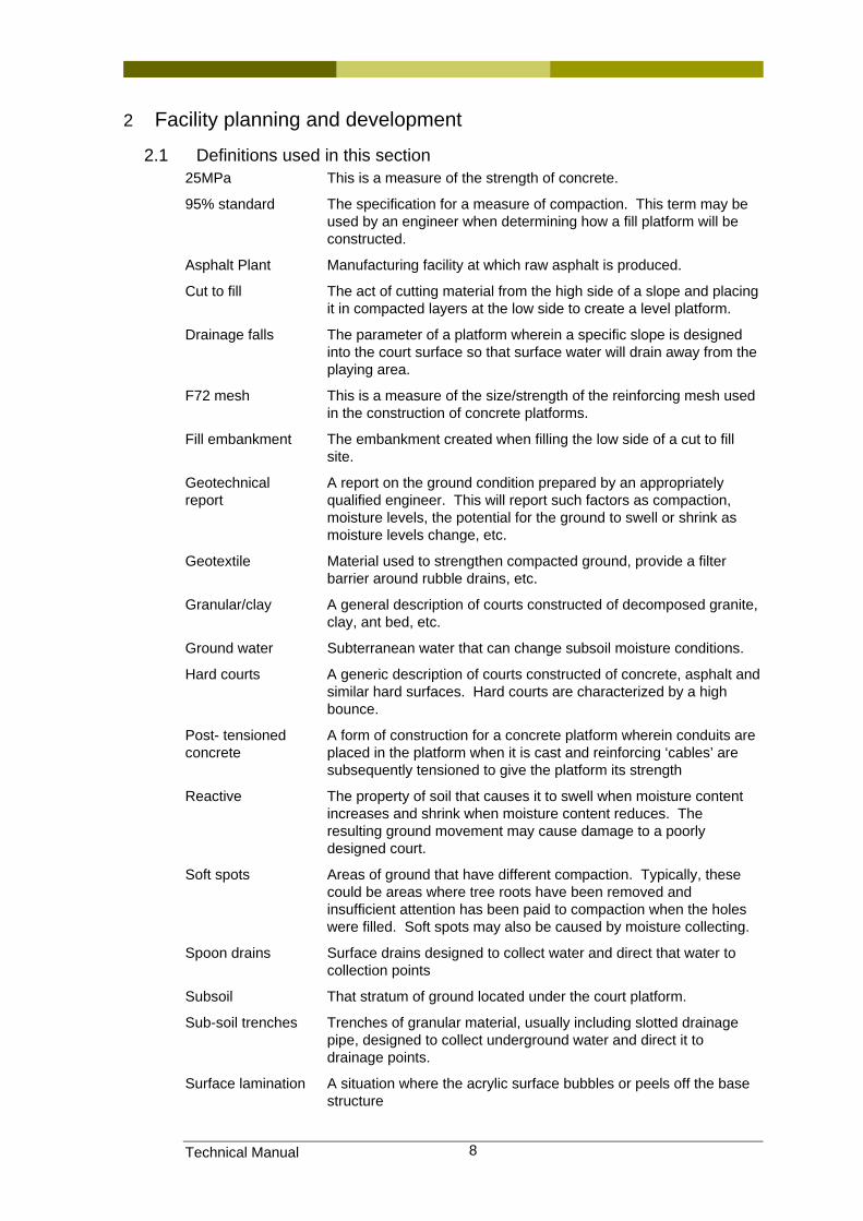
2.1 Definitions used in this section 25MPa This is a measure of the strength of concrete.
95% standard The specification for a measure of compaction. This term may be used by an engineer when determining how a fill platform will be constructed.
Asphalt Plant Manufacturing facility at which raw asphalt is produced.
Cut to fill The act of cutting material from the high side of a slope and placing it in compacted layers at the low side to create a level platform.
Drainage falls The parameter of a platform wherein a specific slope is designed into the court surface so that surface water will drain away from the playing area.
F72 mesh This is a measure of the size/strength of the reinforcing mesh used in the construction of concrete platforms.
Fill embankment The embankment created when filling the low side of a cut to fill site.
Geotechnical report
A report on the ground condition prepared by an appropriately qualified engineer. This will report such factors as compaction, moisture levels, the potential for the ground to swell or shrink as moisture levels change, etc.
Geotextile Material used to strengthen compacted ground, provide a filter barrier around rubble drains, etc.
Granular/clay A general description of courts constructed of decomposed granite, clay, ant bed, etc.
Ground water Subterranean water that can change subsoil moisture conditions.
Hard courts A generic description of courts constructed of concrete, asphalt and similar hard surfaces. Hard courts are characterized by a high bounce.
Post- tensioned concrete
A form of construction for a concrete platform wherein conduits are placed in the platform when it is cast and reinforcing ‘cables’ are subsequently tensioned to give the platform its strength
Reactive The property of soil that causes it to swell when moisture content increases and shrink when moisture content reduces. The resulting ground movement may cause damage to a poorly designed court.
Soft spots Areas of ground that have different compaction. Typically, these could be areas where tree roots have been removed and insufficient attention has been paid to compaction when the holes were filled. Soft spots may also be caused by moisture collecting.
Spoon drains Surface drains designed to collect water and direct that water to collection points
Subsoil That stratum of ground located under the court platform.
Sub-soil trenches Trenches of granular material, usually including slotted drainage pipe, designed to collect underground water and direct it to drainage points.
Surface lamination A situation where the acrylic surface bubbles or peels off the base structure
Technical Manual 9
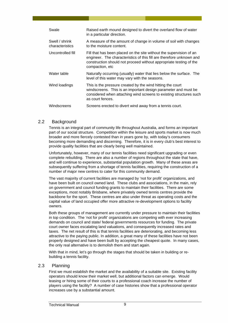
Swale Raised earth mound designed to divert the overland flow of water in a particular direction.
Swell / shrink characteristics
A measure of the amount of change in volume of soil with changes to the moisture content.
Uncontrolled fill Fill that has been placed on the site without the supervision of an engineer. The characteristics of this fill are therefore unknown and construction should not proceed without appropriate testing of the compaction, etc
Water table Naturally occurring (usually) water that lies below the surface. The level of this water may vary with the seasons.
Wind loadings This is the pressure created by the wind hitting the court windscreens. This is an important design parameter and must be considered when attaching wind screens to existing structures such as court fences.
Windscreens Screens erected to divert wind away from a tennis court.
2.2 Background Tennis is an integral part of community life throughout Australia, and forms an important part of our social structure. Competition within the leisure and sports market is now much broader and more fiercely contested than in years gone by, with today’s consumers becoming more demanding and discerning. Therefore, it is in every club’s best interest to provide quality facilities that are clearly being well maintained.
Unfortunately, however, many of our tennis facilities need significant upgrading or even complete rebuilding. There are also a number of regions throughout the state that have, and will continue to experience, substantial population growth. Many of these areas are subsequently suffering from a shortage of tennis facilities, requiring the construction of a number of major new centres to cater for this community demand.
The vast majority of current facilities are managed by ‘not for profit’ organizations, and have been built on council owned land. These clubs and associations, in the main, rely on government and council funding grants to maintain their facilities. There are some exceptions, most notably Brisbane, where privately owned tennis centres provide the backbone for the sport. These centres are also under threat as operating costs and the capital value of land occupied offer more attractive re-development options to facility owners.
Both these groups of management are currently under pressure to maintain their facilities in top condition. The ‘not for profit’ organizations are competing with ever increasing demands on council and state/ federal governments resources for funding. The private court owner faces escalating land valuations, and consequently increased rates and taxes. The net result of this is that tennis facilities are deteriorating, and becoming less attractive to the paying public. In addition, a great many of these facilities have not been properly designed and have been built by accepting the cheapest quote. In many cases, the only real alternative is to demolish them and start again.
With that in mind, let’s go through the stages that should be taken in building or re-building a tennis facility.
2.3 Planning First we must establish the market and the availability of a suitable site. Existing facility operators should know their market well, but additional factors can emerge. Would leasing or hiring some of their courts to a professional coach increase the number of players using the facility? A number of case histories show that a professional operator increases use by a substantial amount.
Technical Manual 10
Consideration should be given to realistic membership numbers and the likely long term requirements of these members with regards to the facilities to be provided. A good source of such information is any other clubs that you may know of that have recently gone through a similar process. The best and most up to date advice is likely to be available by contacting the Tennis Australia member association in your state or territory, e.g. in Queensland contact Tennis Queensland. These member associations have a Technical Services group who can offer expert advice on all facets of developing tennis facilities.
In establishing the market, take into account all of the community groups who could potentially utilise the facility. Tennis coaching, organised fixtures and social activities play a major role in establishing a vibrant tennis club.
To assist with establishing the number of courts on a population basis, the following tables can be used as a guide:
Population No of courts 15,000 20 25,000 30 50,000 50 100,000 80 250,000 130 500,000 210 750,000 270
1,000,000 320
Studies also indicate that facilities should be planned based on population within 15 – 20 minutes driving time from the site.
2.4 Choosing a site Site selection is critical, and a thorough investigation of subsoil and drainage conditions is mandatory. More often than not, a site set aside by local councils for recreational activities is leftover land not suitable for construction of buildings. In the past this was not a huge problem for tennis courts, as the surfaces used were grass or variations of a granular porous surface [decomposed granite, loam, ant-bed, en-tout-cas etc]. These courts could cope with ground movements as they were constantly being well maintained, and in a great number of instances, by volunteer labour.
Today, maintenance costs have become a huge factor and the shift has been to hard courts, and variations of synthetic grass carpets. These types of courts require a well-engineered and constructed base, as ground movements and poor drainage can make them unplayable.
Often, sites set aside for recreational purposes will have the following problems in one form or another:
1] Area contains uncontrolled fill
2] Has a high water table
3] Has an extremely poor soil condition
4] Has bad drainage
5] Is flood prone.
Careful analysis of costs in constructing a long lasting base on sites having any of the above characteristics should be carried out prior to proceeding. On no account should any construction proceed on any site without taking measures to prevent short-term
Technical Manual 11
failure in the base. A comprehensive geotechnical report and cost estimates based on this report must be carried out.
The best solution is to avoid sites with soil and drainage problems. The land may be cheap and / or available, but there is always good reason for this situation.
As a minimum, a suitable site should meet the following requirements:
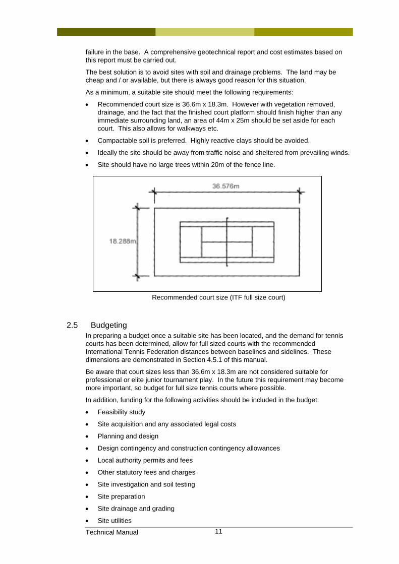
• Recommended court size is 36.6m x 18.3m. However with vegetation removed, drainage, and the fact that the finished court platform should finish higher than any immediate surrounding land, an area of 44m x 25m should be set aside for each court. This also allows for walkways etc.
• Compactable soil is preferred. Highly reactive clays should be avoided.
• Ideally the site should be away from traffic noise and sheltered from prevailing winds.
• Site should have no large trees within 20m of the fence line.
Recommended court size (ITF full size court)
2.5 Budgeting In preparing a budget once a suitable site has been located, and the demand for tennis courts has been determined, allow for full sized courts with the recommended International Tennis Federation distances between baselines and sidelines. These dimensions are demonstrated in Section 4.5.1 of this manual.
Be aware that court sizes less than 36.6m x 18.3m are not considered suitable for professional or elite junior tournament play. In the future this requirement may become more important, so budget for full size tennis courts where possible.
In addition, funding for the following activities should be included in the budget:
• Feasibility study
• Site acquisition and any associated legal costs
• Planning and design
• Design contingency and construction contingency allowances
• Local authority permits and fees
• Other statutory fees and charges
• Site investigation and soil testing
• Site preparation
• Site drainage and grading
• Site utilities
Technical Manual 12
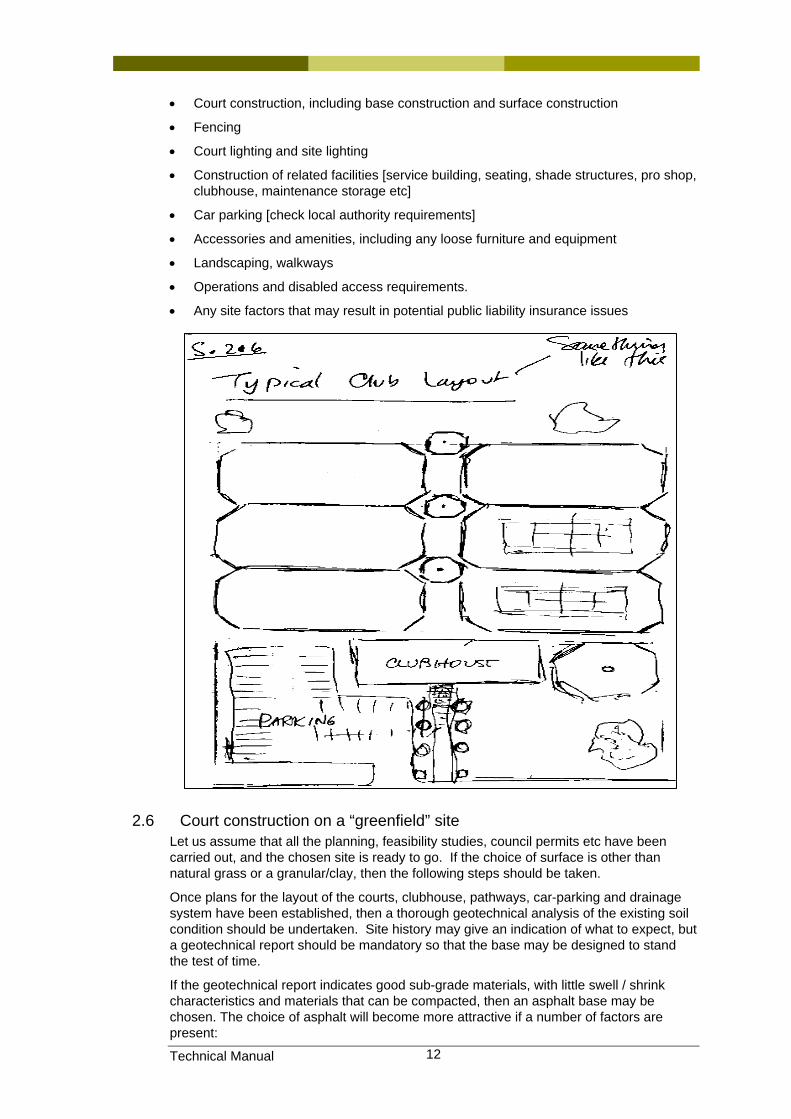
• Court construction, including base construction and surface construction
• Fencing
• Court lighting and site lighting
• Construction of related facilities [service building, seating, shade structures, pro shop, clubhouse, maintenance storage etc]
• Car parking [check local authority requirements]
• Accessories and amenities, including any loose furniture and equipment
• Landscaping, walkways
• Operations and disabled access requirements.
• Any site factors that may result in potential public liability insurance issues
2.6 Court construction on a “greenfield” site Let us assume that all the planning, feasibility studies, council permits etc have been carried out, and the chosen site is ready to go. If the choice of surface is other than natural grass or a granular/clay, then the following steps should be taken.
Once plans for the layout of the courts, clubhouse, pathways, car-parking and drainage system have been established, then a thorough geotechnical analysis of the existing soil condition should be undertaken. Site history may give an indication of what to expect, but a geotechnical report should be mandatory so that the base may be designed to stand the test of time.
If the geotechnical report indicates good sub-grade materials, with little swell / shrink characteristics and materials that can be compacted, then an asphalt base may be chosen. The choice of asphalt will become more attractive if a number of factors are present:
Technical Manual 13
1] Non-reactive soil
2] Asphalt plant within easy access
3] More than 1 or 2 courts being constructed.
If a single or double court is to be constructed, then reinforced concrete may be the better alternative. Concrete is probably the only choice if the soil condition indicates high reactivity, or the site could be subjected to periodic flooding. In some cases post- tensioned concrete should be the choice. Many areas in Australia have highly reactive soils. Courts built in these areas with under-designed bases have failed within a short period of time. This decision must only be made with assistance from a geotechnical engineer.
2.6.1 Asphalt base – acrylic surface Let us assume the site we have chosen has good subgrade characteristics, and we are constructing a 6-8 court complex with access to an asphalt plant.
The site should first be cleared of all vegetation and topsoil, and court platforms established. Topsoil can be stockpiled for later use. If trees are to be cleared, then the tree roots must also be removed. If tree roots and/or topsoil are left on site, then fungal growth and settlement can occur under the courts some time in the future.
Holes left by tree root removal should be filled with crushed rock material compacted in layers.
More information on site preparation is contained in Section 4.
The court platforms should be cut to provide the required drainage falls in one plane. This can be end to end, side to side, or diagonally. The fall should be a minimum of 1% in the one plane. In most cases, the platform is cut with a 1% slope end to end, and a 0.5% slope side to side. This delivers a diagonal fall of approximately 1.1%.
Each court or multiple court platforms should be constructed so that it is at least 150mm higher than any immediately surrounding land. This ensures that, in combination with sub-surface drainage, no ground water can seep under the court platform.
The courts should be aligned north-south, but may be a few degrees off this alignment if site conditions favour this alternative. In Australia the western sun causes the most discomfort for playing, so a court may be aligned a few degrees east of north to compensate for this factor.
The platform should also be cut so that surface drainage can be adequately disposed of. It is not desirable to have surface water drain across more than three courts, as drying time can be delayed, and cause problems in conducting fixtures and tournaments.
In addition, for Australian conditions, it is preferable to have the courts drain from north to south, or diagonally to the southeast or southwest. This will facilitate drying in the winter months.
Proper drainage is most important, and must be catered for in the initial cutting out or establishing the court platform. Ground water seeping under the court surface or water tables rising to just beneath the playing surface will cause problems in the future. Sub-soil drainage should not be installed beneath the court base. Water getting under the base can cause movement of lighting poles, net posts and fence post foundations, surface lamination and heaving of the surface. Further information is provided in Section 4.7.
Drainage can be a combination of swales, spoon drains and sub-soil trenches around the exterior of the courts. In some cases, a grated drain [not a spoon drain] may be necessary to prevent surface water running across a battery of more than three courts.
Before proceeding with base construction, the platforms should be proof rolled, and any ‘soft spots’ cut out and replaced and compacted with suitable fill. If the platform consists of a ‘cut to fill’ construction, then all fill must be compacted in layers of not more than 150mm. The platform thus created should be at least 2metres longer and 2metres wider
Technical Manual 14
than the court fence line dimensions, i.e. 38.6metres x 20.3 metres. Further detail on compaction is provided in Section 5.6.
Beyond this platform the ground should slope away in all directions so that the entire platform is at least 150mm above the swale or slope thus created.
Wherever possible it is best to create the platform slope back into the cut location. This prevents any surface run-off water running over the filled slope and causing erosion. The surface run-off water must then be collected and disposed of so that it does not run back under the court.
If it is not possible to slope the court back into the cut because of site constraints, then surface water must be channelled away from the fill embankment. This can be done by way of a spoon drain or upright kerb outside the fence line. The water must then be collected in a sump and piped away to an appropriate discharge point.
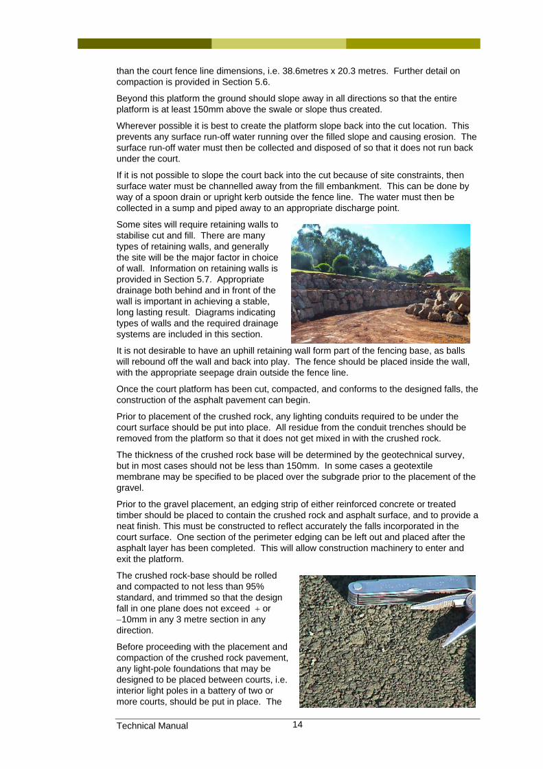
Some sites will require retaining walls to stabilise cut and fill. There are many types of retaining walls, and generally the site will be the major factor in choice of wall. Information on retaining walls is provided in Section 5.7. Appropriate drainage both behind and in front of the wall is important in achieving a stable, long lasting result. Diagrams indicating types of walls and the required drainage systems are included in this section.
It is not desirable to have an uphill retaining wall form part of the fencing base, as balls will rebound off the wall and back into play. The fence should be placed inside the wall, with the appropriate seepage drain outside the fence line.
Once the court platform has been cut, compacted, and conforms to the designed falls, the construction of the asphalt pavement can begin.
Prior to placement of the crushed rock, any lighting conduits required to be under the court surface should be put into place. All residue from the conduit trenches should be removed from the platform so that it does not get mixed in with the crushed rock.
The thickness of the crushed rock base will be determined by the geotechnical survey, but in most cases should not be less than 150mm. In some cases a geotextile membrane may be specified to be placed over the subgrade prior to the placement of the gravel.
Prior to the gravel placement, an edging strip of either reinforced concrete or treated timber should be placed to contain the crushed rock and asphalt surface, and to provide a neat finish. This must be constructed to reflect accurately the falls incorporated in the court surface. One section of the perimeter edging can be left out and placed after the asphalt layer has been completed. This will allow construction machinery to enter and exit the platform.
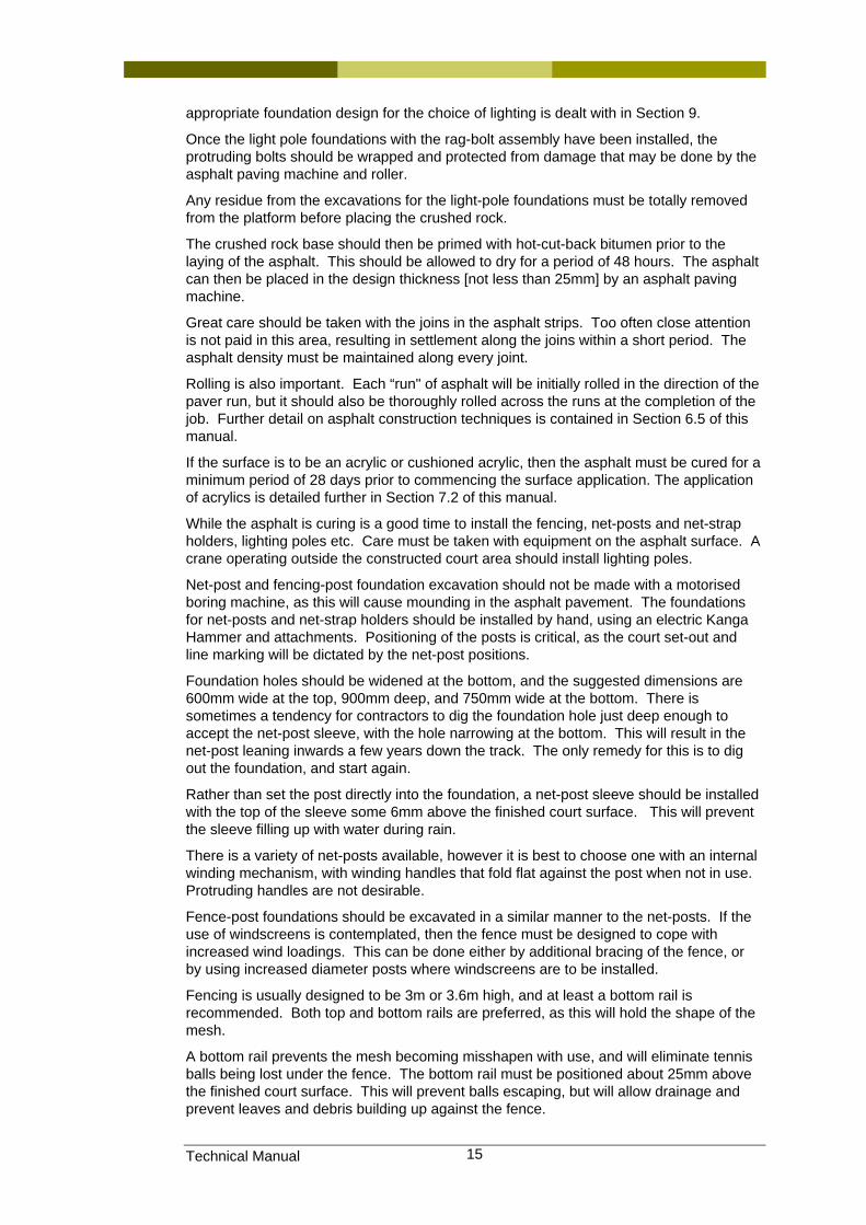
The crushed rock-base should be rolled and compacted to not less than 95% standard, and trimmed so that the design fall in one plane does not exceed + or −10mm in any 3 metre section in any direction.
Before proceeding with the placement and compaction of the crushed rock pavement, any light-pole foundations that may be designed to be placed between courts, i.e. interior light poles in a battery of two or more courts, should be put in place. The
Technical Manual 15
appropriate foundation design for the choice of lighting is dealt with in Section 9.
Once the light pole foundations with the rag-bolt assembly have been installed, the protruding bolts should be wrapped and protected from damage that may be done by the asphalt paving machine and roller.
Any residue from the excavations for the light-pole foundations must be totally removed from the platform before placing the crushed rock.
The crushed rock base should then be primed with hot-cut-back bitumen prior to the laying of the asphalt. This should be allowed to dry for a period of 48 hours. The asphalt can then be placed in the design thickness [not less than 25mm] by an asphalt paving machine.
Great care should be taken with the joins in the asphalt strips. Too often close attention is not paid in this area, resulting in settlement along the joins within a short period. The asphalt density must be maintained along every joint.
Rolling is also important. Each “run" of asphalt will be initially rolled in the direction of the paver run, but it should also be thoroughly rolled across the runs at the completion of the job. Further detail on asphalt construction techniques is contained in Section 6.5 of this manual.
If the surface is to be an acrylic or cushioned acrylic, then the asphalt must be cured for a minimum period of 28 days prior to commencing the surface application. The application of acrylics is detailed further in Section 7.2 of this manual.
While the asphalt is curing is a good time to install the fencing, net-posts and net-strap holders, lighting poles etc. Care must be taken with equipment on the asphalt surface. A crane operating outside the constructed court area should install lighting poles.
Net-post and fencing-post foundation excavation should not be made with a motorised boring machine, as this will cause mounding in the asphalt pavement. The foundations for net-posts and net-strap holders should be installed by hand, using an electric Kanga Hammer and attachments. Positioning of the posts is critical, as the court set-out and line marking will be dictated by the net-post positions.
Foundation holes should be widened at the bottom, and the suggested dimensions are 600mm wide at the top, 900mm deep, and 750mm wide at the bottom. There is sometimes a tendency for contractors to dig the foundation hole just deep enough to accept the net-post sleeve, with the hole narrowing at the bottom. This will result in the net-post leaning inwards a few years down the track. The only remedy for this is to dig out the foundation, and start again.
Rather than set the post directly into the foundation, a net-post sleeve should be installed with the top of the sleeve some 6mm above the finished court surface. This will prevent the sleeve filling up with water during rain.
There is a variety of net-posts available, however it is best to choose one with an internal winding mechanism, with winding handles that fold flat against the post when not in use. Protruding handles are not desirable.
Fence-post foundations should be excavated in a similar manner to the net-posts. If the use of windscreens is contemplated, then the fence must be designed to cope with increased wind loadings. This can be done either by additional bracing of the fence, or by using increased diameter posts where windscreens are to be installed.
Fencing is usually designed to be 3m or 3.6m high, and at least a bottom rail is recommended. Both top and bottom rails are preferred, as this will hold the shape of the mesh.
A bottom rail prevents the mesh becoming misshapen with use, and will eliminate tennis balls being lost under the fence. The bottom rail must be positioned about 25mm above the finished court surface. This will prevent balls escaping, but will allow drainage and prevent leaves and debris building up against the fence.
Technical Manual 16
If courts are constructed side by side or in a battery, then the dividing fence may be lowered to 1.2m high through the central section. Positioning of light poles may dictate the lower area, and some examples of fencing configuration are shown on the following pages.
Wind-screening to the perimeter of the court[s] is desirable. Allowances should be made in the court design for spectator viewing.
There are several types of fencing available, and they include galvanised, powder coated or PVC coated.
Installation of the fence-post footings should be by hand, and designed to cope with the prevailing ground conditions and wind loadings. If wind-screens are used, then the fence posts must be upgraded or braced to withstand the wind loading. The fencing can be designed with either square or cut-off corners. If truncated corners are used on a full sized court, then allow for 3 metre truncations. The truncated corners allow for a few desirable factors –
• More aesthetic appearance
• Gate entrance to each court at corner of court
• Elimination of ‘dead ball’ corners.
The wire mesh should always be hung on the inside of the court, with care taken not to damage the asphalt surface during this procedure.
More information and detail of fence construction is available in Section 8 of this manual.
2.6.2 Concrete base Construction of a concrete base is provided in detail in Section 6.6 of this manual. As previously stated, concrete should be the choice if a single or double court installation is contemplated, or existing sub-grade conditions dictate an asphalt base would not be suitable. A geotechnical investigation must be carried out on any site that may have potential problems – expansive soils or uncontrolled fill etc.
Once this report is available, the concrete base can be designed to cope with prevailing conditions. In some cases, the only course of action would be to construct a post-tensioned slab. Using a basic concrete specification of 100mm of 25MPA concrete and F72 mesh on ground with high plasticity will not work. Within a few years the court may be unfit for play.
Apart from the base material chosen, the other aspects of the tennis facility design and construction would be the same as for an asphalt base.
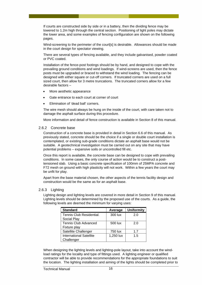
2.6.3 Lighting Lighting design and lighting levels are covered in more detail in Section 9 of this manual. Lighting levels should be determined by the proposed use of the courts. As a guide, the following levels are deemed the minimum for varying uses:
Standard Average Uniformity Tennis Club Residential. Social Play
300 lux 2.0
Tennis Club Advanced Fixture play
500 lux 2.0
Satellite Challenger 750 lux 1.7 International Satellite Challenger
1,250 lux 1.5
When designing the lighting levels and lighting-pole layout, take into account the wind-load ratings for the locality and type of fittings used. A lighting engineer or qualified contractor will be able to provide recommendations for the appropriate foundations to suit the location. The lighting installation and aiming of the lights should be completed prior to
Technical Manual 17
applying the court surface. All construction and erection of fences, light poles, net-post sleeves etc should be completed before the court surface is laid.
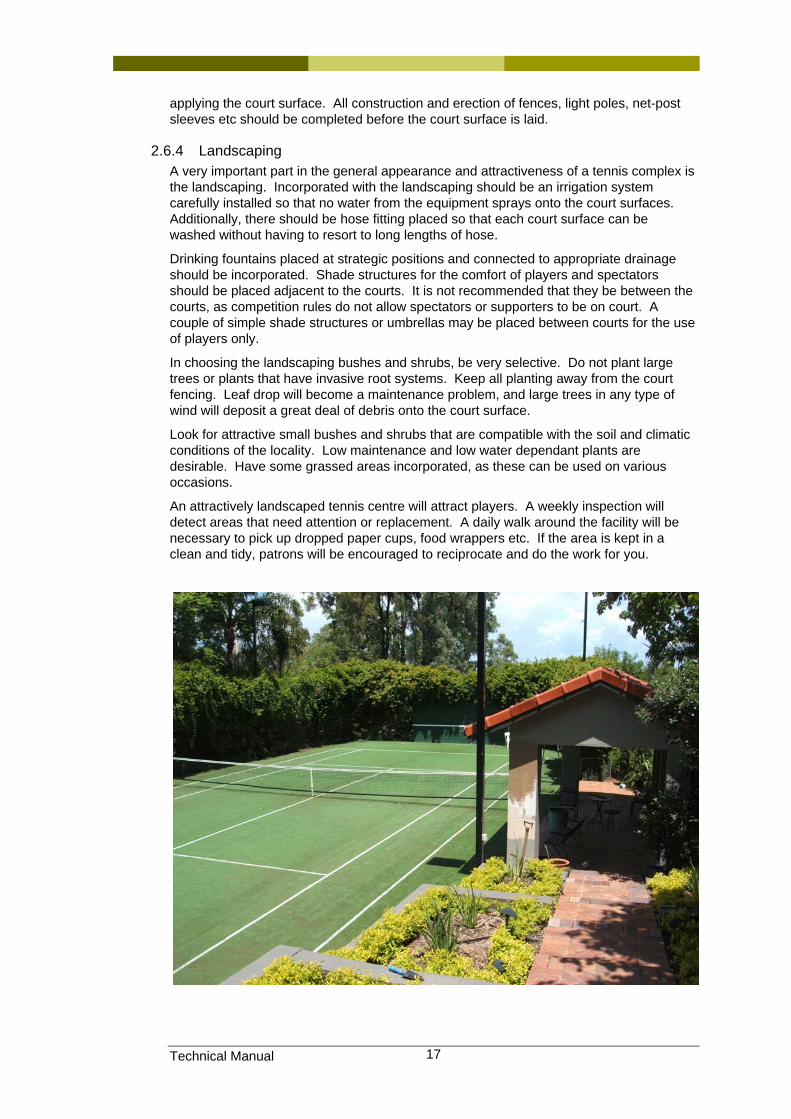
2.6.4 Landscaping A very important part in the general appearance and attractiveness of a tennis complex is the landscaping. Incorporated with the landscaping should be an irrigation system carefully installed so that no water from the equipment sprays onto the court surfaces. Additionally, there should be hose fitting placed so that each court surface can be washed without having to resort to long lengths of hose.
Drinking fountains placed at strategic positions and connected to appropriate drainage should be incorporated. Shade structures for the comfort of players and spectators should be placed adjacent to the courts. It is not recommended that they be between the courts, as competition rules do not allow spectators or supporters to be on court. A couple of simple shade structures or umbrellas may be placed between courts for the use of players only.
In choosing the landscaping bushes and shrubs, be very selective. Do not plant large trees or plants that have invasive root systems. Keep all planting away from the court fencing. Leaf drop will become a maintenance problem, and large trees in any type of wind will deposit a great deal of debris onto the court surface.
Look for attractive small bushes and shrubs that are compatible with the soil and climatic conditions of the locality. Low maintenance and low water dependant plants are desirable. Have some grassed areas incorporated, as these can be used on various occasions.
An attractively landscaped tennis centre will attract players. A weekly inspection will detect areas that need attention or replacement. A daily walk around the facility will be necessary to pick up dropped paper cups, food wrappers etc. If the area is kept in a clean and tidy, patrons will be encouraged to reciprocate and do the work for you.
Technical Manual 18
3 Facilities development planning
3.1 Introduction Having established the feasibility of a refurbishing, expanding rebuilding or constructing a new facility, there are still many steps yet to be taken before we arrive at a well finished and fully operational tennis facility. This process is generally best controlled by an experienced Project Manager, preferably with a solid understanding of the intricacies of developing a tennis facility.
3.2 Definitions used in this section Life Cycle Costing Study undertaken to compare not only the initial installation costs
but also the ongoing costs to maintain the serviceability of a facility or an element of that facility (i.e. the playing surface of a tennis court) over a fixed period of time with other available alternatives
Orientation Axis upon which the length of a tennis court is placed (i.e. North-South or East-West)
Project Management
Suitably qualified expert who is engaged by a client to oversee the design and construction processes of a project (in this instance, tennis related facilities).
3.3 Project Management Many club’s and tennis centre owners have tried to manage the design and construction processes of their new or improved facilities with varying degrees of success. Some clubs are fortunate enough to have had a committee and/or club member/s with sufficient skills to manage this task, which can take anything from a few months to a few years to progress from the feasibility stages right through to the completion of construction. At times this can be a very time consuming role, and given most clubs rely on volunteers, this can impact on the ability of these people to maintain control and progress of the development through to completion.
Whilst many of these people are familiar with the basic requirements of a tennis court and associated ancillary structures, many have very little comprehension of the specialist engineering knowledge that is required in the design of such structures. Some of these design considerations will be discussed in detail throughout this manual to give the average club member at least a rudimentary understanding of these requirements.
There are all too many horror stories of courts that have been built without taking into account the prevailing soil conditions, insufficient provisions for site drainage, using the wrong materials, poor construction practices or even something as simple as the incorrect court orientation in relation to the sun. A failure to take some or all of these sorts of issues into account can lead to substantial or even catastrophic failures of the courts themselves, all in a relatively short space of time.
Significant ongoing maintenance costs or rectification works could end up being as expensive as the original installation costs or more, especially if it means demolition and starting again. In many instances, these bodies would have been far better off engaging a specialist Project Manager to oversee their project to ensure clubs are not exposing themselves to such risks. This is particularly relevant to smaller clubs who struggle for many years to raise the capital required to undertake such relatively major works.
For the sake of a small proportion of the overall development costs, the engagement of a well qualified Project Manager should considerably minimise their client’s risk exposure. Not only could a good Project Manager save these bodies from costly mistakes during design and construction, they should also be able to provide advice regarding life cycle costing issues, which are equally important to all court owners. (Life cycle costing is discussed in more detail a little later in this Section of the manual.) The last thing a client wants, after outlaying good money for their facility, is to be burdened with the heartache
Technical Manual 19
of considerable ongoing maintenance costs for many years to come due to decisions made during design development without such forethought.
As previously stated in the previous section of this manual, the best and most up to date advice is likely to be available by contacting the Tennis Australia member association in you state or territory, e.g. in Queensland contact Tennis Queensland. These member associations have a Technical Services group who can offer services from expert advice on simple issues right through to full Project Management of major capital works projects.
3.4 Funding Funding grants for sporting clubs are available from all levels of government, Federal, State and Local. Further information can be obtained from these bodies or by contacting Tennis Queensland.
Tennis Australia and Tennis Queensland offer facility development loans at very competitive rates for affiliated clubs and associations. Further information can be obtained by contacting Tennis Queensland
3.5 Ongoing costs Whole of life or life cycle costing.
When choosing elements of a facility the ongoing maintenance costs need to be considered as part of the establishment cost. For example, choosing a budget priced acrylic surface with a shorter service life may cost more in the long run than a quality product. Replacing a budget product may also introduce problems as the lesser product may require significant effort and expense to remove prior to replacing it with a quality product.
Similar issues apply for other surface products, fencing, lighting and particularly base construction.
3.6 Information sources, Standards and Codes. Not applicable.
Technical Manual 20
4 General site and construction considerations
4.1 Introduction Choice of site is important. In addition to location, access and those other factors that provide access to members and therefore membership growth, the geotechnical conditions of the site have a significant effect on construction and maintenance costs.
4.2 Definitions used in this section Cut-off drains Trenches of granular material, usually including slotted drainage
pipe, designed to collect underground water and direct it to drainage points.
ITF International Tennis Federation. The ITF is the governing body of the sport of tennis. The ITF publish the rules of tennis on their web site at www.itftennis.com.
Overland flow of water
Water flowing across the surface of the ground caused by rain etc. This may be greater than expected where rainfall is collected by large impervious areas such as car parks and roofs of structures.
Reactive The property of soil that causes it to swell when moisture content increases and shrink when moisture content reduces. The resulting ground movement may cause damage to a poorly designed court.
Shrink/swell A measure of the amount of change in volume of soil with changes to the moisture content.
Subgrade Describes the earth structure underneath the court base.
Uncontrolled fill Material that has been used to fill depressions, valleys etc that has not been selected and/or placed under appropriate supervision. Uncontrolled fill presents as a major future risk to construction work.
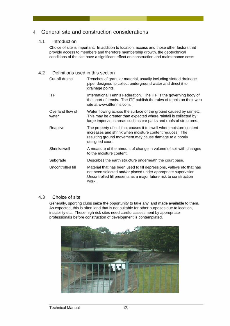
4.3 Choice of site Generally, sporting clubs seize the opportunity to take any land made available to them. As expected, this is often land that is not suitable for other purposes due to location, instability etc. These high risk sites need careful assessment by appropriate professionals before construction of development is contemplated.
Technical Manual 21
4.4 High risk sites
4.4.1 Slip areas Areas close to hillsides where instability occurs require particular engineering approaches. These areas are often subject to Local Government regulation regarding type of building work that can be carried out and engineering required for that building work. These engineering requirements can add significantly to construction costs but must not be compromised.
4.4.2 Uncontrolled fill and other issues “Uncontrolled fill” refers to sites that have been re-profiled, usually by the introduction of imported material, without appropriate engineering supervision or treatment.
Imported fill must be carefully selected to ensure it does not contain material that will change its characteristics over time or with changes to environmental conditions, such as moisture content.
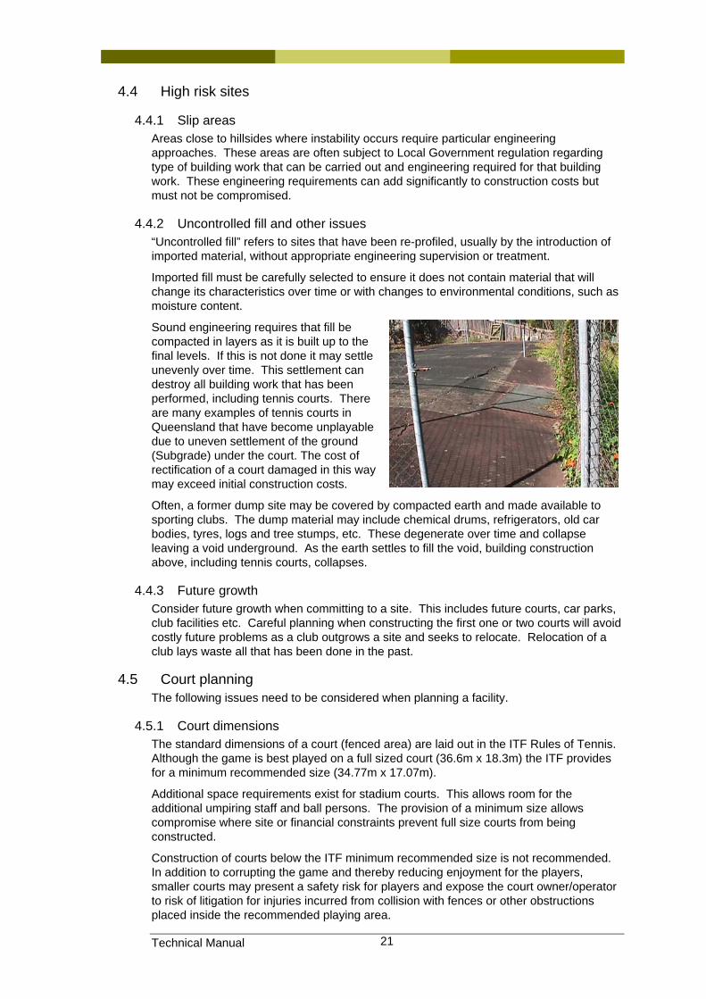
Sound engineering requires that fill be compacted in layers as it is built up to the final levels. If this is not done it may settle unevenly over time. This settlement can destroy all building work that has been performed, including tennis courts. There are many examples of tennis courts in Queensland that have become unplayable due to uneven settlement of the ground (Subgrade) under the court. The cost of rectification of a court damaged in this way may exceed initial construction costs.
Often, a former dump site may be covered by compacted earth and made available to sporting clubs. The dump material may include chemical drums, refrigerators, old car bodies, tyres, logs and tree stumps, etc. These degenerate over time and collapse leaving a void underground. As the earth settles to fill the void, building construction above, including tennis courts, collapses.
4.4.3 Future growth Consider future growth when committing to a site. This includes future courts, car parks, club facilities etc. Careful planning when constructing the first one or two courts will avoid costly future problems as a club outgrows a site and seeks to relocate. Relocation of a club lays waste all that has been done in the past.
4.5 Court planning The following issues need to be considered when planning a facility.
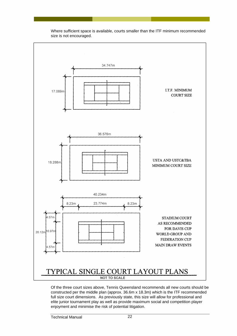
4.5.1 Court dimensions The standard dimensions of a court (fenced area) are laid out in the ITF Rules of Tennis. Although the game is best played on a full sized court (36.6m x 18.3m) the ITF provides for a minimum recommended size (34.77m x 17.07m).
Additional space requirements exist for stadium courts. This allows room for the additional umpiring staff and ball persons. The provision of a minimum size allows compromise where site or financial constraints prevent full size courts from being constructed.
Construction of courts below the ITF minimum recommended size is not recommended. In addition to corrupting the game and thereby reducing enjoyment for the players, smaller courts may present a safety risk for players and expose the court owner/operator to risk of litigation for injuries incurred from collision with fences or other obstructions placed inside the recommended playing area.
Technical Manual 22
Where sufficient space is available, courts smaller than the ITF minimum recommended size is not encouraged.
Of the three court sizes above, Tennis Queensland recommends all new courts should be constructed per the middle plan (approx. 36.6m x 18.3m) which is the ITF recommended full size court dimensions. As previously state, this size will allow for professional and elite junior tournament play as well as provide maximum social and competition player enjoyment and minimise the risk of potential litigation.
Technical Manual 23
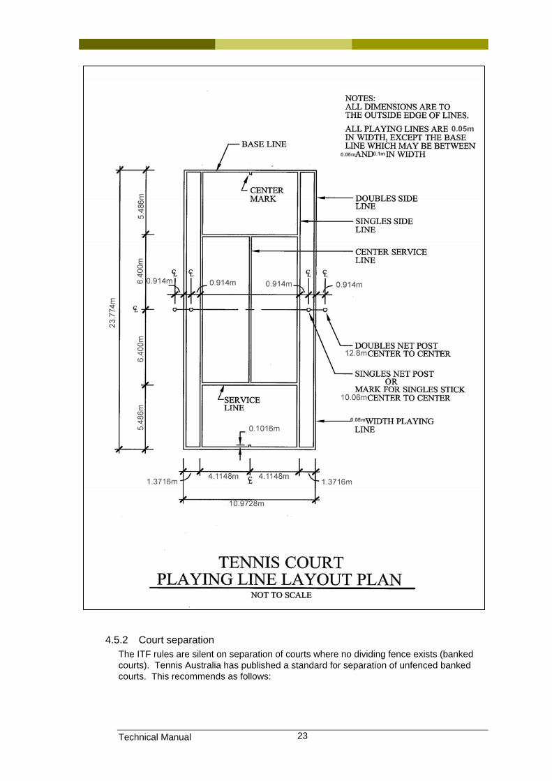
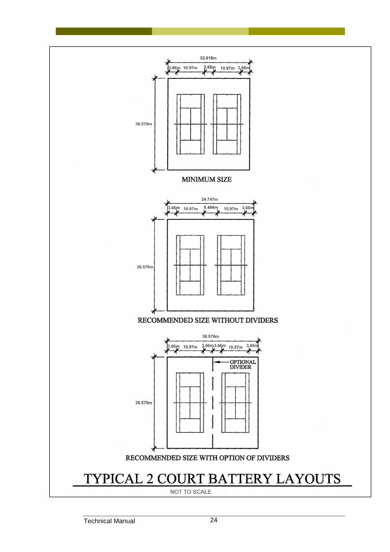
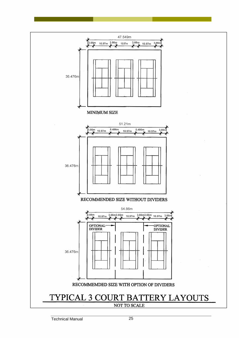
4.5.2 Court separation The ITF rules are silent on separation of courts where no dividing fence exists (banked courts). Tennis Australia has published a standard for separation of unfenced banked courts. This recommends as follows:
Technical Manual 24
Technical Manual 25
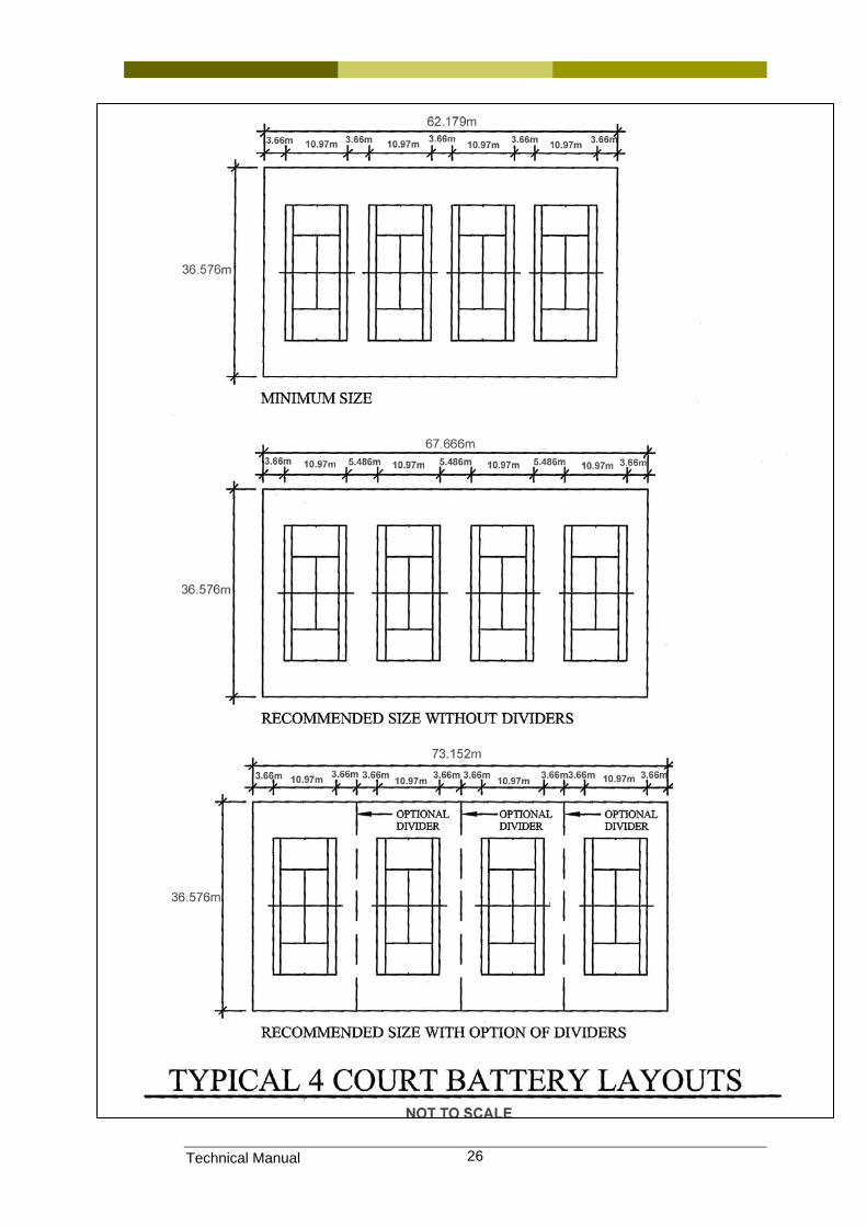
Technical Manual 26
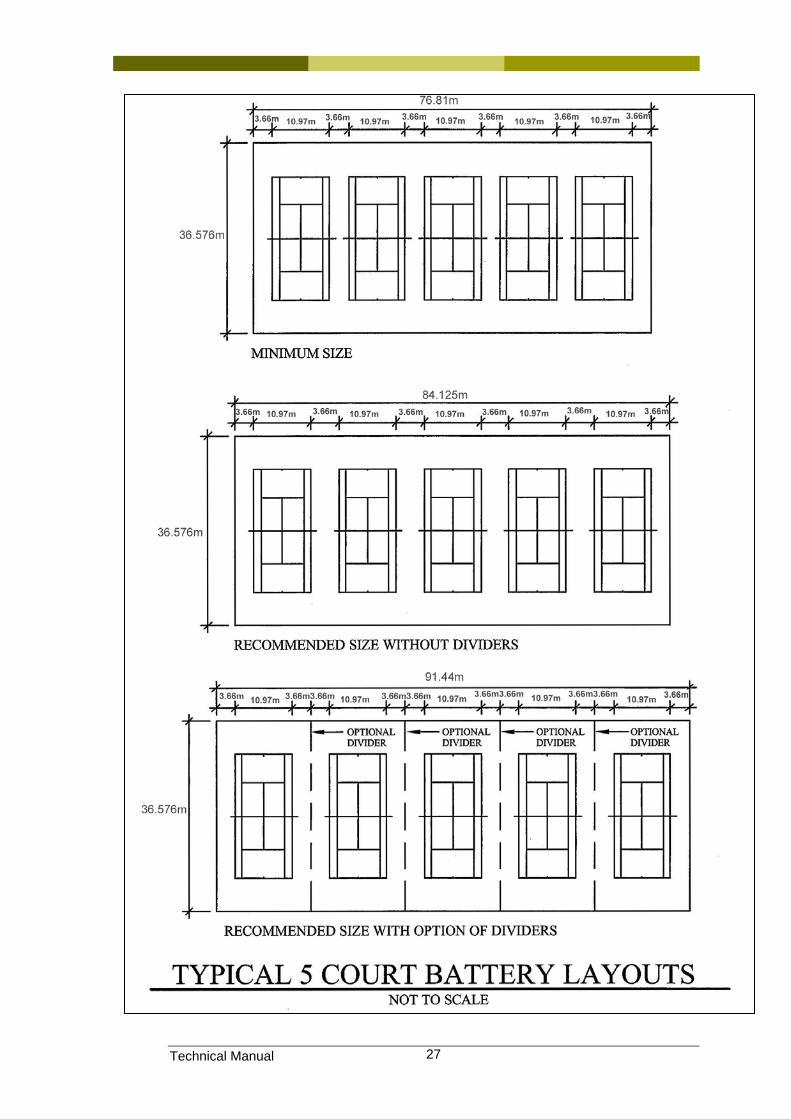
Technical Manual 27
Technical Manual 28
4.5.3 Dividing fences Dividing fences separate courts where banked court arrangements exist. The inclusion of a dividing fence increases the size of the base structure as the run-off from the sideline to the fence (doubled) is greater than the distance between sidelines on courts without dividing fences. This increases the total court area and consequently the cost of construction and maintenance.
However, dividing fences, even if low height (say 1200mm) or partial fences, improve enjoyment of players as they contain balls on the court. They reduce the need to fetch stray balls, and subsequently the incidence of a ball from one court disrupting play on an adjoining court. Stray balls may also lead to trip injuries to players, and therefore presents an additional risk factor that could lead to litigation costs.
Tennis Queensland recommends the inclusion of dividing fences on banked courts. Further detail of court dividing fences is provided in Section 8.
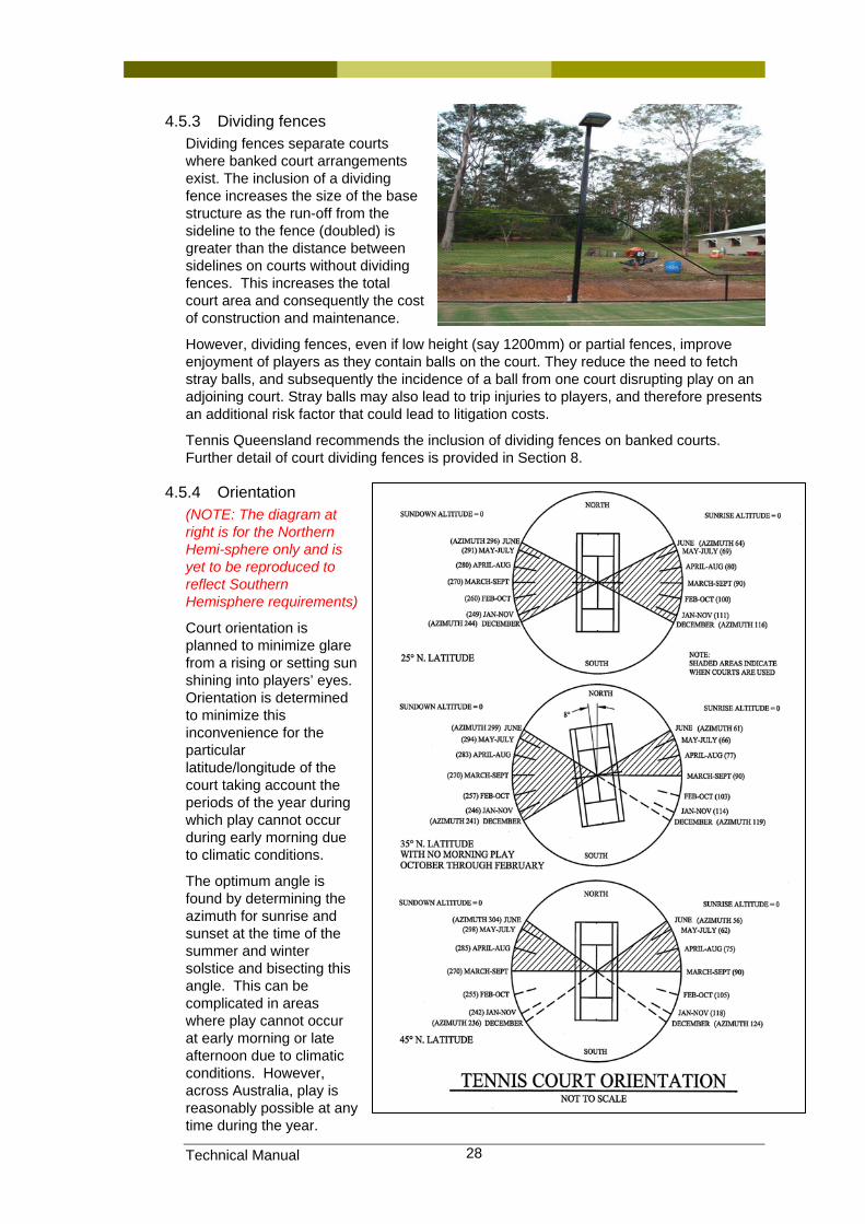
4.5.4 Orientation (NOTE: The diagram at right is for the Northern Hemi-sphere only and is yet to be reproduced to reflect Southern Hemisphere requirements)
Court orientation is planned to minimize glare from a rising or setting sun shining into players’ eyes. Orientation is determined to minimize this inconvenience for the particular latitude/longitude of the court taking account the periods of the year during which play cannot occur during early morning due to climatic conditions.
The optimum angle is found by determining the azimuth for sunrise and sunset at the time of the summer and winter solstice and bisecting this angle. This can be complicated in areas where play cannot occur at early morning or late afternoon due to climatic conditions. However, across Australia, play is reasonably possible at any time during the year.
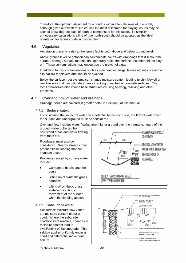
Technical Manual 29
Therefore, the optimum alignment for a court is within a few degrees of true north, although given our western sun causes the most discomfort for playing, courts may be aligned a few degrees east of north to compensate for this factor. To simplify unnecessary calculations a line of true north-south should be adopted as the ideal orientation for tennis courts in this country.
4.6 Vegetation Vegetation presents a risk to the tennis facility both above and below ground level.
Above ground level, vegetation can contaminate courts with droppings that discolour the surface, damage surface material and generally make the surface uncomfortable to play on. These contaminations may encourage the growth of algae.
In addition to this, contaminations such as pine needles, twigs, leaves etc may present a slip hazard for players and should be avoided.
Below the surface, root systems can change moisture content leading to shrink/swell of reactive soils that can ultimately cause cracking of asphalt or concrete surfaces. The roots themselves also invade base structures causing heaving, cracking and other problems.
4.7 Overland flow of water and drainage Drainage issues are covered in greater detail in Section 5 of this manual.
4.7.1 Surface water. In considering the impact of water on a potential tennis court site, the flow of water over the surface and underground must be considered.
Overland flow includes water flowing from higher ground over the natural contours of the ground, water collected from hardstand areas and water flowing from roofs etc.
Floodwater must also be considered. Nearby streams may produce flash flooding that can inundate a court.
Problems caused by surface water include:
• Carriage of debris onto the court
• Silting up of synthetic grass surfaces
• Lifting of synthetic grass surfaces resulting in movement of the surface when the flooding abates.
4.7.2 Subsurface water Subsurface moisture flow varies the moisture content under a court. Where the subgrade conditions are reactive, changes in moisture content lead to swell/shrink of the subgrade. This seldom applies uniformly under a court and differential movement occurs.

Technical Manual 30
Over a single cycle subsurface moisture changes can lead to unevenness of the surface. Over multiple cycles, damage to the base structure can occur.
Treatment of subsurface water is a design element of the court construction. Cut-off drains and similar treatments are recommended.
4.8 Choice of contractor Tennis Queensland cannot make recommendations regarding the worth or otherwise of individual tennis court builders. To do this would require a monitoring of every court builders’ ongoing performance and resources are clearly not available to do this.
However, Tennis Queensland has sought and obtained assurances from the Sports Constructors’ Association regarding the performance of their builder members. Tennis Queensland has influence with this association.
While one cannot assume that builders who are not members of that association will not provide quality of service, affiliated clubs and associations are encouraged to invite quotes from members of the Sports Constructors Association. A list of their members is available on the web site at www.sportscontractors.com.au
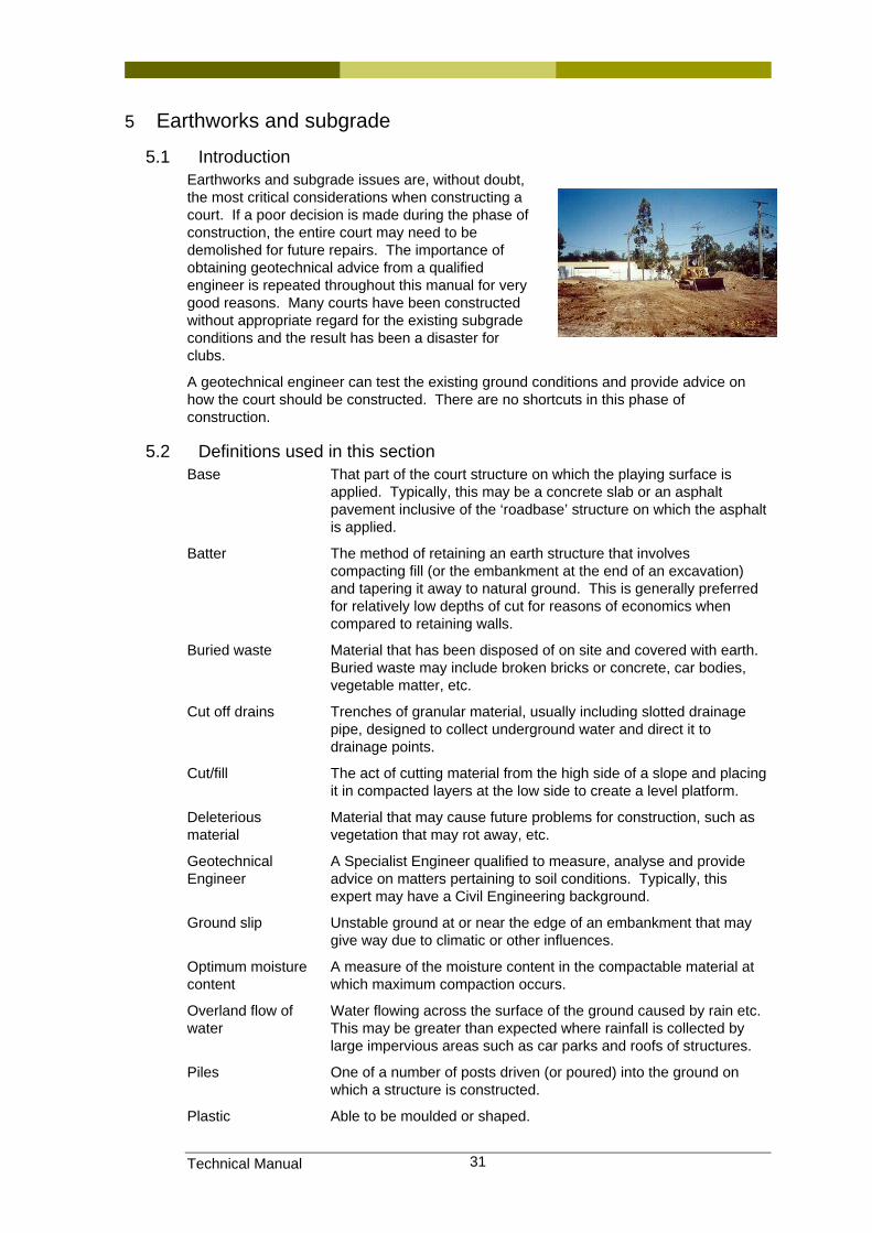
Technical Manual 31
5 Earthworks and subgrade
5.1 Introduction Earthworks and subgrade issues are, without doubt, the most critical considerations when constructing a court. If a poor decision is made during the phase of construction, the entire court may need to be demolished for future repairs. The importance of obtaining geotechnical advice from a qualified engineer is repeated throughout this manual for very good reasons. Many courts have been constructed without appropriate regard for the existing subgrade conditions and the result has been a disaster for clubs.
A geotechnical engineer can test the existing ground conditions and provide advice on how the court should be constructed. There are no shortcuts in this phase of construction.
5.2 Definitions used in this section Base That part of the court structure on which the playing surface is
applied. Typically, this may be a concrete slab or an asphalt pavement inclusive of the ‘roadbase’ structure on which the asphalt is applied.
Batter The method of retaining an earth structure that involves compacting fill (or the embankment at the end of an excavation) and tapering it away to natural ground. This is generally preferred for relatively low depths of cut for reasons of economics when compared to retaining walls.
Buried waste Material that has been disposed of on site and covered with earth. Buried waste may include broken bricks or concrete, car bodies, vegetable matter, etc.
Cut off drains Trenches of granular material, usually including slotted drainage pipe, designed to collect underground water and direct it to drainage points.
Cut/fill The act of cutting material from the high side of a slope and placing it in compacted layers at the low side to create a level platform.
Deleterious material
Material that may cause future problems for construction, such as vegetation that may rot away, etc.
Geotechnical Engineer
A Specialist Engineer qualified to measure, analyse and provide advice on matters pertaining to soil conditions. Typically, this expert may have a Civil Engineering background.
Ground slip Unstable ground at or near the edge of an embankment that may give way due to climatic or other influences.
Optimum moisture content
A measure of the moisture content in the compactable material at which maximum compaction occurs.
Overland flow of water
Water flowing across the surface of the ground caused by rain etc. This may be greater than expected where rainfall is collected by large impervious areas such as car parks and roofs of structures.
Piles One of a number of posts driven (or poured) into the ground on which a structure is constructed.
Plastic Able to be moulded or shaped.
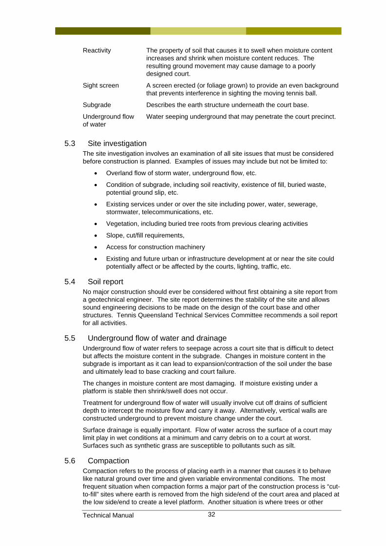
Technical Manual 32
Reactivity The property of soil that causes it to swell when moisture content increases and shrink when moisture content reduces. The resulting ground movement may cause damage to a poorly designed court.
Sight screen A screen erected (or foliage grown) to provide an even background that prevents interference in sighting the moving tennis ball.
Subgrade Describes the earth structure underneath the court base.
Underground flow of water
Water seeping underground that may penetrate the court precinct.
5.3 Site investigation The site investigation involves an examination of all site issues that must be considered before construction is planned. Examples of issues may include but not be limited to:
• Overland flow of storm water, underground flow, etc.
• Condition of subgrade, including soil reactivity, existence of fill, buried waste, potential ground slip, etc.
• Existing services under or over the site including power, water, sewerage, stormwater, telecommunications, etc.
• Vegetation, including buried tree roots from previous clearing activities
• Slope, cut/fill requirements,
• Access for construction machinery
• Existing and future urban or infrastructure development at or near the site could potentially affect or be affected by the courts, lighting, traffic, etc.
5.4 Soil report No major construction should ever be considered without first obtaining a site report from a geotechnical engineer. The site report determines the stability of the site and allows sound engineering decisions to be made on the design of the court base and other structures. Tennis Queensland Technical Services Committee recommends a soil report for all activities.
5.5 Underground flow of water and drainage Underground flow of water refers to seepage across a court site that is difficult to detect but affects the moisture content in the subgrade. Changes in moisture content in the subgrade is important as it can lead to expansion/contraction of the soil under the base and ultimately lead to base cracking and court failure.
The changes in moisture content are most damaging. If moisture existing under a platform is stable then shrink/swell does not occur.
Treatment for underground flow of water will usually involve cut off drains of sufficient depth to intercept the moisture flow and carry it away. Alternatively, vertical walls are constructed underground to prevent moisture change under the court.
Surface drainage is equally important. Flow of water across the surface of a court may limit play in wet conditions at a minimum and carry debris on to a court at worst. Surfaces such as synthetic grass are susceptible to pollutants such as silt.
5.6 Compaction Compaction refers to the process of placing earth in a manner that causes it to behave like natural ground over time and given variable environmental conditions. The most frequent situation when compaction forms a major part of the construction process is “cut-to-fill” sites where earth is removed from the high side/end of the court area and placed at the low side/end to create a level platform. Another situation is where trees or other
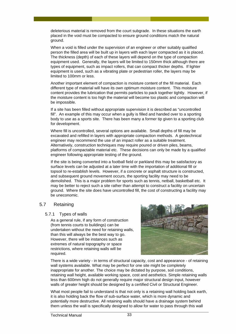
Technical Manual 33
deleterious material is removed from the court subgrade. In these situations the earth placed in the void must be compacted to ensure ground conditions match the natural ground.
When a void is filled under the supervision of an engineer or other suitably qualified person the filled area will be built up in layers with each layer compacted as it is placed. The thickness (depth) of each of these layers will depend on the type of compaction equipment used. Generally, the layers will be limited to 150mm thick although there are types of equipment, such as impact rollers, that can compact thicker depths. If lighter equipment is used, such as a vibrating plate or pedestrian roller, the layers may be limited to 100mm or less.
Another important element of compaction is moisture content of the fill material. Each different type of material will have its own optimum moisture content. This moisture content provides the lubrication that permits particles to pack together tightly. However, if the moisture content is too high the material will become too plastic and compaction will be impossible.
If a site has been filled without appropriate supervision it is described as “uncontrolled fill”. An example of this may occur when a gully is filled and handed over to a sporting body to use as a sports site. There has been many a former tip given to a sporting club for development.
Where fill is uncontrolled, several options are available. Small depths of fill may be excavated and refilled in layers with appropriate compaction methods. A geotechnical engineer may recommend the use of an impact roller as a suitable treatment. Alternatively, construction techniques may require poured or driven piles, beams, platforms of compactable material etc. These decisions can only be made by a qualified engineer following appropriate testing of the ground.
If the site is being converted into a football field or parkland this may be satisfactory as surface levels can be adjusted at a later time with the importation of additional fill or topsoil to re-establish levels. However, if a concrete or asphalt structure is constructed, and subsequent ground movement occurs, the sporting facility may need to be demolished. This is a major problem for sports such as tennis, netball, basketball etc. It may be better to reject such a site rather than attempt to construct a facility on uncertain ground. Where the site does have uncontrolled fill, the cost of constructing a facility may be uneconomic.
5.7 Retaining
5.7.1 Types of walls As a general rule, if any form of construction (from tennis courts to buildings) can be undertaken without the need for retaining walls, than this will always be the best way to go. However, there will be instances such as extremes of natural topography or space restrictions, where retaining walls will be required.
There is a wide variety - in terms of structural capacity, cost and appearance - of retaining wall systems available. What may be perfect for one site might be completely inappropriate for another. The choice may be dictated by purpose, soil conditions, retaining wall height, available working space, cost and aesthetics. Simple retaining walls less than 600mm high do not generally require major structural design input, however walls of greater height should be designed by a certified Civil or Structural Engineer.
What most people fail to understand is that not only is a retaining wall holding back earth, it is also holding back the flow of sub-surface water, which is more dynamic and potentially more destructive. All retaining walls should have a drainage system behind them unless the wall is specifically designed to allow for water to pass through this wall
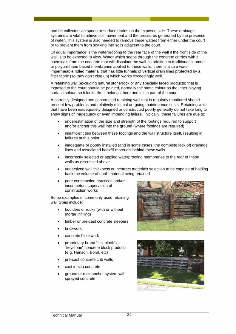
Technical Manual 34
and be collected via spoon or surface drains on the exposed side. These drainage systems are vital to relieve soil movement and the pressures generated by the presence of water. This system is also needed to remove these waters from either under the court or to prevent them from soaking into soils adjacent to the court.
Of equal importance is the waterproofing to the rear face of the wall if the front side of the wall is to be exposed to view. Water which seeps through the concrete carries with it chemicals from the concrete that will discolour the wall. In addition to traditional bitumen or polyurethane based membranes applied to these walls, there is also a water impermeable rolled material that has little tunnels of vertical drain lines protected by a filter fabric (so they don’t clog up) which works exceedingly well.
A retaining wall (excluding natural stone/rock or any specially faced products) that is exposed to the court should be painted, normally the same colour as the inner playing surface colour, so it looks like it belongs there and it is a part of the court.
A correctly designed and constructed retaining wall that is regularly monitored should present few problems and relatively minimal on-going maintenance costs. Retaining walls that have been inadequately designed or constructed poorly generally do not take long to show signs of inadequacy or even impending failure. Typically, these failures are due to:
• underestimation of the size and strength of the footings required to support and/or anchor this wall into the ground (where footings are required)
• insufficient ties between these footings and the wall structure itself, resulting in failures at this point
• inadequate or poorly installed (and in some cases, the complete lack of) drainage lines and associated backfill materials behind these walls
• incorrectly selected or applied waterproofing membranes to the rear of these walls as discussed above
• undersized wall thickness or incorrect materials selection to be capable of holding back the volume of earth material being retained
• poor construction practices and/or incompetent supervision of construction works
Some examples of commonly used retaining wall types include:
• boulders or rocks (with or without mortar infilling)
• timber or pre-cast concrete sleepers
• brickwork
• concrete blockwork
• proprietary brand “link block” or “keystone” concrete block products (e.g. Hanson, Boral, etc)
• pre-cast concrete crib walls
• cast in-situ concrete
• ground or rock anchor system with sprayed concrete
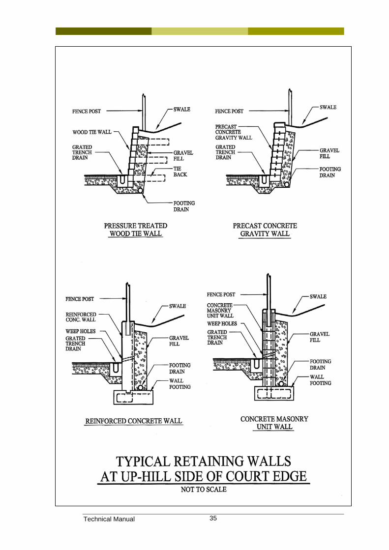
Technical Manual 35
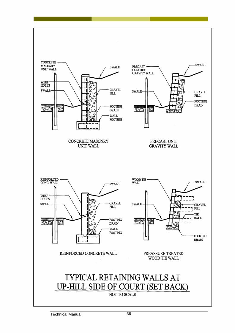
Technical Manual 36
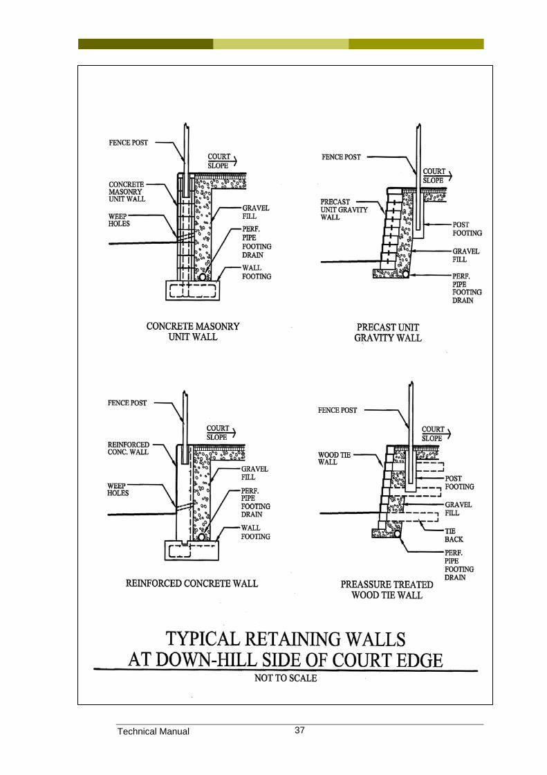
Technical Manual 37
Technical Manual 38
5.8 Site maintenance
5.8.1 Control of vegetation Vegetation can cause major problems for tennis court structures. While they may be aesthetically pleasing, provide shade for spectators and can act as a sight screen or wind break, tree roots can cause significant damage to the court base.
Tree roots are attracted to the court base as the moisture content below the court is maintained at a higher rate than surrounding ground as evaporation is limited.
When tree roots penetrate the court subgrade they increase in size and provide upward pressure under the court base. Tree roots can be observed under an asphalt court as irregular cracks radiating from the tree. Concrete courts are also lifted and crack under the differential pressures resulting from the upward pressure of the tree root and the voids either side. Often, this leads to a trip hazard occurring along the line of the construction joint, saw cut joint, etc.
The planting of nearby trees should be avoided where the root system can reach the court platform. Each variety has a reasonably predictable root distance. This information is available from appropriately qualified persons.
Technical Manual 39
6 Base construction
6.1 Introduction
6.2 Definitions used in this section
Asphalt batching plant
Manufacturing facility at which asphalt is produced prior to delivery to site and laying.
Asphaltic cement (AC)
Manufactured asphalt product used for the wearing surfaces on tennis courts, car parks, roadways etc. Often referred to as “bitumen”.
Bedding sand Graded river sand placed under a concrete slab.
Bobcat Small to medium sized (skid-steer) machine used in earthmoving.
Cement stabilized A process where cement is mixed with earth material in smaller quantities to provide greater binding power and hence strength.
Cementitous fillers. Rigid fillers used for repairs to hard surfaces such as asphalt or concrete. These are usually cement based.
Elastomeric (flexible) fillers
Flexible polymer based fillers used to repair asphalt or concrete that allows some movement without breaking out.
Cold joints Term used in asphalt construction to describe the joins between successive passes of the asphalt laying machine where adhesion between the rows is unsatisfactory. In concrete construction, it describes the joins between separate batches of concrete where adhesion is incomplete.
Compressive strength
The strength of a product to resist construction by compression.
Construction film Often called “builders’ film” or “visqueen”, this plastic film is delivered in rolls and used to provide a barrier between concrete being placed and the earth below.
Construction joints Joints intentionally placed in a concrete slab to localize cracking caused by concrete shrinkage during curing.
Crack control joints Refer to “construction joints” above.
Crusher dust Sand sized particles that are a by-product of crushing rock.
Curing The process during which concrete undergoes the chemical reaction causing it to harden and achieve full strength.
Curing agents Chemical agents that control the curing process of concrete to increase the strength of the slab.
Defects liability period
Period during which the constructor is responsible for failure.
De-lamination Failure of a product that results in it flaking off in layers.
Dowel joints A form of construction joint in which a number of steel rods or “dowels” are used to connect two separate slabs. One end of the dowel is usually cast in the first slab and the other end greased or placed in a sheath to allow it to slip in and out of the other portion of the slab. The function of the dowel is to allow horizontal movement but prevent vertical movement of the two sections of slab that may produce a slip hazard.
Edge beam A rigid beam, usually reinforced concrete providing strength to the
Technical Manual 40
edge of an asphalt or concrete slab.
Elastomeric Flexible. Used to describe flexible fillers.
Plane The description of the surface indicating that it is not bowed, or humped.
Falls A measure of the slope of the surface.
Boxing (formwork) Removable former used to contain concrete until it has hardened.
Granular layer Layer of base material under asphalt formed by compacting granular material such as crushed rock that provides the strength of the base.
Helicopter Mechanical trowel used to achieve planarity in a concrete slab, so named because of the rotating blades.
Light broom” finish A method of achieving a finely textured finish on concrete by lightly drawing a fine broom across the surface as the concrete is hardening.
Pavers or Paving machine
Machine used to place asphalt that includes rollers.
Ponding In a finished court this refers to defects in the surface in which water lies rather than draining away. In concrete curing, it refers to the intentional creation of dams to trap water over the surface and slow the curing process.
Portland cement Pure cement, without additives.
Post stressing A form of concrete slab construction in which conduits or pipes are placed in the slab during the pour and high tensile cables are strained immediately afterwards to provide strength to the slab.
Prime coat In asphalting, this refers to a bituminous material spayed on to the crushed rock base that penetrates the base prior to chemically changing to act as a binding agent.
Proprietary systems
Describes any system used in construction where the installer has exclusive rights to its use.
Reinforced concrete
Often described as “pre tensioned”. Reinforcing steel is placed prior to the concrete to provide tensile strength to the slab.
Roadbase Crushed rock material where different sized material is prepared in a manner that maximizes compacted strength.
Shrinkage cracks Cracks appearing in concrete during curing that are caused by the natural shrinking action.
Smooth drum vibrating roller
Roller used for compacting materials that uses a smooth drum that is mechanically vibrated to increase compaction.
“Soffcut” joints Joints cut into concrete as soon as the slab can support foot traffic. These joints are usually 3mm wide and 25mm deep and provide an intentionally ‘weak’ point where shrinkage cracking will occur in a controlled way.
Tensile strength Strength of a product to withstand being ‘pulled apart’.
Tramlines Doubles lines on the court line marking.
Viscosity Density of a liquid, measured by the ability of a material to flow through an aperture at a particular rate.
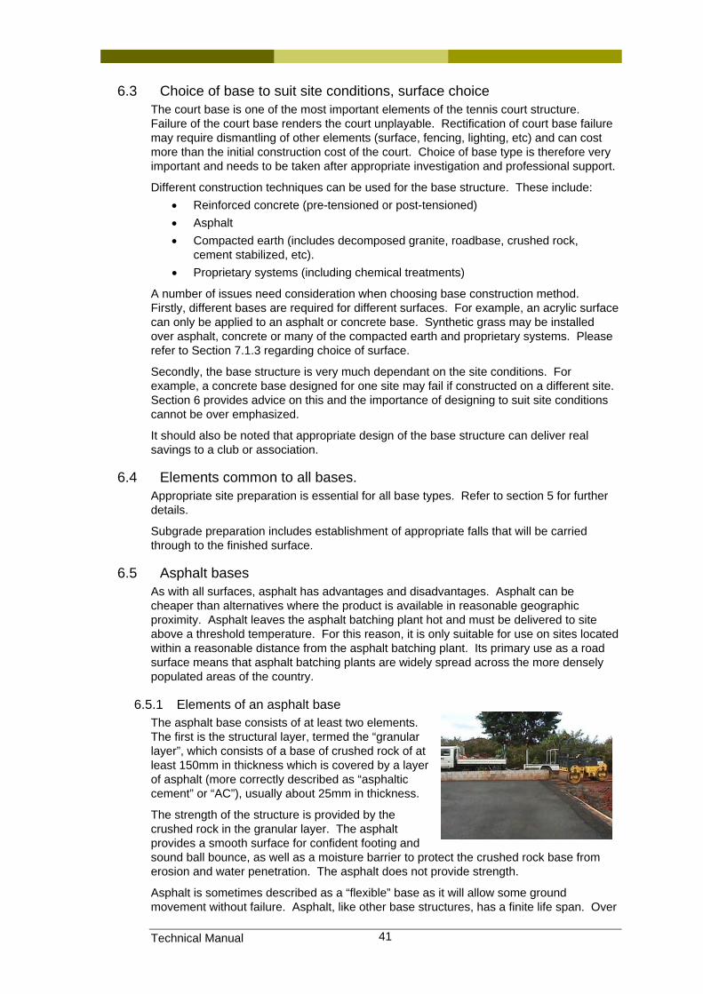
Technical Manual 41
6.3 Choice of base to suit site conditions, surface choice The court base is one of the most important elements of the tennis court structure. Failure of the court base renders the court unplayable. Rectification of court base failure may require dismantling of other elements (surface, fencing, lighting, etc) and can cost more than the initial construction cost of the court. Choice of base type is therefore very important and needs to be taken after appropriate investigation and professional support.
Different construction techniques can be used for the base structure. These include: • Reinforced concrete (pre-tensioned or post-tensioned) • Asphalt • Compacted earth (includes decomposed granite, roadbase, crushed rock,
cement stabilized, etc). • Proprietary systems (including chemical treatments)
A number of issues need consideration when choosing base construction method. Firstly, different bases are required for different surfaces. For example, an acrylic surface can only be applied to an asphalt or concrete base. Synthetic grass may be installed over asphalt, concrete or many of the compacted earth and proprietary systems. Please refer to Section 7.1.3 regarding choice of surface.
Secondly, the base structure is very much dependant on the site conditions. For example, a concrete base designed for one site may fail if constructed on a different site. Section 6 provides advice on this and the importance of designing to suit site conditions cannot be over emphasized.
It should also be noted that appropriate design of the base structure can deliver real savings to a club or association.
6.4 Elements common to all bases. Appropriate site preparation is essential for all base types. Refer to section 5 for further details.
Subgrade preparation includes establishment of appropriate falls that will be carried through to the finished surface.
6.5 Asphalt bases As with all surfaces, asphalt has advantages and disadvantages. Asphalt can be cheaper than alternatives where the product is available in reasonable geographic proximity. Asphalt leaves the asphalt batching plant hot and must be delivered to site above a threshold temperature. For this reason, it is only suitable for use on sites located within a reasonable distance from the asphalt batching plant. Its primary use as a road surface means that asphalt batching plants are widely spread across the more densely populated areas of the country.
6.5.1 Elements of an asphalt base The asphalt base consists of at least two elements. The first is the structural layer, termed the “granular layer”, which consists of a base of crushed rock of at least 150mm in thickness which is covered by a layer of asphalt (more correctly described as “asphaltic cement” or “AC”), usually about 25mm in thickness.
The strength of the structure is provided by the crushed rock in the granular layer. The asphalt provides a smooth surface for confident footing and sound ball bounce, as well as a moisture barrier to protect the crushed rock base from erosion and water penetration. The asphalt does not provide strength.
Asphalt is sometimes described as a “flexible” base as it will allow some ground movement without failure. Asphalt, like other base structures, has a finite life span. Over
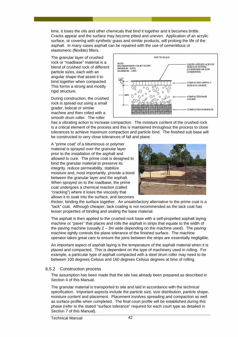
Technical Manual 42
time, it loses the oils and other chemicals that bind it together and it becomes brittle. Cracks appear and the surface may become pitted and uneven. Application of an acrylic surface, or covering with synthetic grass and similar products, will prolong the life of the asphalt. In many cases asphalt can be repaired with the use of cementitous or elastomeric (flexible) fillers.
The granular layer of crushed rock or “roadbase” material is a blend of crushed rock of different particle sizes, each with an angular shape that assist it to bind together when compacted. This forms a strong and mostly rigid structure.
During construction, the crushed rock is spread out using a small grader, bobcat or similar machine and then rolled with a smooth drum roller. The roller has a vibrating action to increase compaction. The moisture content of the crushed rock is a critical element of the process and this is maintained throughout the process to close tolerances to achieve maximum compaction and particle bind. The finished sub base will be constructed to very close tolerances of fall and plane.
A “prime coat” of a bituminous or polymer material is sprayed over the granular layer prior to the installation of the asphalt and allowed to cure. The prime coat is designed to bind the granular material to preserve its integrity, reduce permeability, stabilize moisture and, most importantly, provide a bond between the granular layer and the asphalt. When sprayed on to the roadbase, the prime coat undergoes a chemical reaction (called “cracking”) where it loses the viscosity that allows it to soak into the surface, and becomes thicker, binding the surface together. An unsatisfactory alternative to the prime coat is a “tack” coat. Although cheaper, tack coating is not recommended as the tack coat has lesser properties of binding and sealing the base material.
The asphalt is then applied to the crushed rock base with a self-propelled asphalt laying machine or “paver” that places and rolls the asphalt in strips that equate to the width of the paving machine (usually 2 – 3m wide depending on the machine used). The paving machine tightly controls the plane tolerance of the finished surface. The machine operator takes great care to ensure the joins between the strips are essentially negligible.
An important aspect of asphalt laying is the temperature of the asphalt material when it is placed and compacted. This is dependent on the type of machinery used in rolling. For example, a particular type of asphalt compacted with a steel drum roller may need to be between 100 degrees Celsius and 160 degrees Celsius degrees at time of rolling.
6.5.2 Construction process The assumption has been made that the site has already been prepared as described in Section 4 of this Manual.
The granular material is transported to site and laid in accordance with the technical specification. Important aspects include the particle size, size distribution, particle shape, moisture content and placement. Placement involves spreading and compaction as well as surface profile when completed. The final court profile will be established during this phase (refer to the stated “surface tolerance” required for each court type as detailed in Section 7 of this Manual).
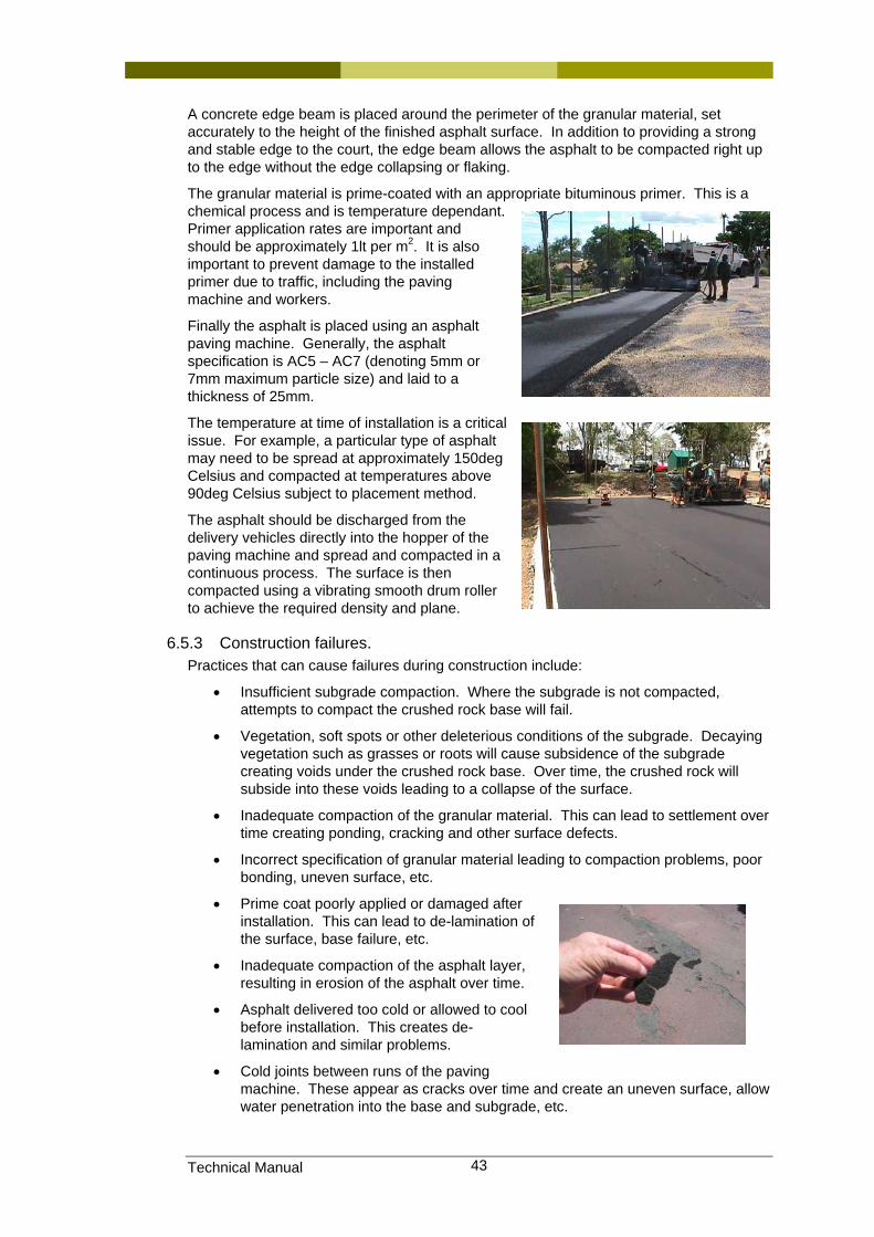
Technical Manual 43
A concrete edge beam is placed around the perimeter of the granular material, set accurately to the height of the finished asphalt surface. In addition to providing a strong and stable edge to the court, the edge beam allows the asphalt to be compacted right up to the edge without the edge collapsing or flaking.
The granular material is prime-coated with an appropriate bituminous primer. This is a chemical process and is temperature dependant. Primer application rates are important and should be approximately 1lt per m2. It is also important to prevent damage to the installed primer due to traffic, including the paving machine and workers.
Finally the asphalt is placed using an asphalt paving machine. Generally, the asphalt specification is AC5 – AC7 (denoting 5mm or 7mm maximum particle size) and laid to a thickness of 25mm.
The temperature at time of installation is a critical issue. For example, a particular type of asphalt may need to be spread at approximately 150deg Celsius and compacted at temperatures above 90deg Celsius subject to placement method.
The asphalt should be discharged from the delivery vehicles directly into the hopper of the paving machine and spread and compacted in a continuous process. The surface is then compacted using a vibrating smooth drum roller to achieve the required density and plane.
6.5.3 Construction failures. Practices that can cause failures during construction include:
• Insufficient subgrade compaction. Where the subgrade is not compacted, attempts to compact the crushed rock base will fail.
• Vegetation, soft spots or other deleterious conditions of the subgrade. Decaying vegetation such as grasses or roots will cause subsidence of the subgrade creating voids under the crushed rock base. Over time, the crushed rock will subside into these voids leading to a collapse of the surface.
• Inadequate compaction of the granular material. This can lead to settlement over time creating ponding, cracking and other surface defects.
• Incorrect specification of granular material leading to compaction problems, poor bonding, uneven surface, etc.
• Prime coat poorly applied or damaged after installation. This can lead to de-lamination of the surface, base failure, etc.
• Inadequate compaction of the asphalt layer, resulting in erosion of the asphalt over time.
• Asphalt delivered too cold or allowed to cool before installation. This creates de-lamination and similar problems.
• Cold joints between runs of the paving machine. These appear as cracks over time and create an uneven surface, allow water penetration into the base and subgrade, etc.
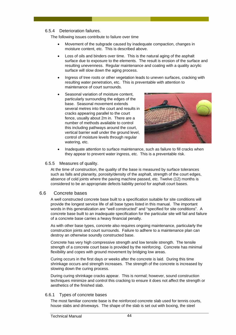
Technical Manual 44
6.5.4 Deterioration failures. The following issues contribute to failure over time
• Movement of the subgrade caused by inadequate compaction, changes in moisture content, etc. This is described above.
• Loss of oils and binders over time. This is the natural aging of the asphalt surface due to exposure to the elements. The result is erosion of the surface and resulting unevenness. Regular maintenance and coating with a quality acrylic surface will slow down the aging process.
• Ingress of tree roots or other vegetation leads to uneven surfaces, cracking with resulting water penetration, etc. This is preventable with attention to maintenance of court surrounds.
• Seasonal variation of moisture content, particularly surrounding the edges of the base. Seasonal movement extends several metres into the court and results in cracks appearing parallel to the court fence, usually about 2m in. There are a number of methods available to control this including pathways around the court, vertical barrier wall under the ground level, control of moisture levels through regular watering, etc.
• Inadequate attention to surface maintenance, such as failure to fill cracks when they appear to prevent water ingress, etc. This is a preventable risk.
6.5.5 Measures of quality. At the time of construction, the quality of the base is measured by surface tolerances such as falls and planarity, porosity/density of the asphalt, strength of the court edges, absence of cold joints where the paving machine passed, etc. Twelve (12) months is considered to be an appropriate defects liability period for asphalt court bases.
6.6 Concrete bases A well constructed concrete base built to a specification suitable for site conditions will provide the longest service life of all base types listed in this manual. The important words in this generalization are “well constructed” and “specified for site conditions”. A concrete base built to an inadequate specification for the particular site will fail and failure of a concrete base carries a heavy financial penalty.
As with other base types, concrete also requires ongoing maintenance, particularly the construction joints and court surrounds. Failure to adhere to a maintenance plan can destroy an otherwise soundly constructed base.
Concrete has very high compressive strength and low tensile strength. The tensile strength of a concrete court base is provided by the reinforcing. Concrete has minimal flexibility and copes with ground movement by bridging low areas.
Curing occurs in the first days or weeks after the concrete is laid. During this time shrinkage occurs and strength increases. The strength of the concrete is increased by slowing down the curing process.
During curing shrinkage cracks appear. This is normal; however, sound construction techniques minimize and control this cracking to ensure it does not affect the strength or aesthetics of the finished slab.
6.6.1 Types of concrete bases The most familiar concrete base is the reinforced concrete slab used for tennis courts, house slabs and driveways. The shape of the slab is set out with boxing, the steel
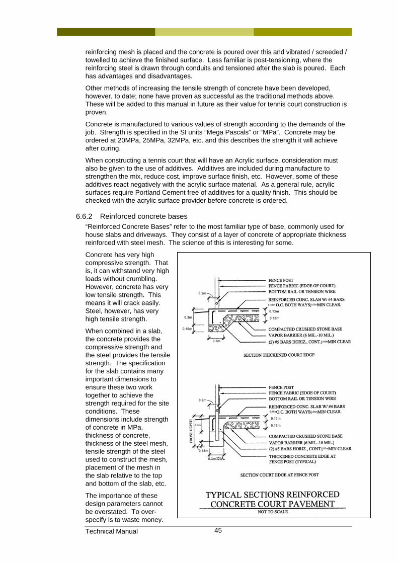
Technical Manual 45
reinforcing mesh is placed and the concrete is poured over this and vibrated / screeded / towelled to achieve the finished surface. Less familiar is post-tensioning, where the reinforcing steel is drawn through conduits and tensioned after the slab is poured. Each has advantages and disadvantages.
Other methods of increasing the tensile strength of concrete have been developed, however, to date; none have proven as successful as the traditional methods above. These will be added to this manual in future as their value for tennis court construction is proven.
Concrete is manufactured to various values of strength according to the demands of the job. Strength is specified in the SI units “Mega Pascals” or “MPa”. Concrete may be ordered at 20MPa, 25MPa, 32MPa, etc. and this describes the strength it will achieve after curing.
When constructing a tennis court that will have an Acrylic surface, consideration must also be given to the use of additives. Additives are included during manufacture to strengthen the mix, reduce cost, improve surface finish, etc. However, some of these additives react negatively with the acrylic surface material. As a general rule, acrylic surfaces require Portland Cement free of additives for a quality finish. This should be checked with the acrylic surface provider before concrete is ordered.
6.6.2 Reinforced concrete bases “Reinforced Concrete Bases” refer to the most familiar type of base, commonly used for house slabs and driveways. They consist of a layer of concrete of appropriate thickness reinforced with steel mesh. The science of this is interesting for some.
Concrete has very high compressive strength. That is, it can withstand very high loads without crumbling. However, concrete has very low tensile strength. This means it will crack easily. Steel, however, has very high tensile strength.
When combined in a slab, the concrete provides the compressive strength and the steel provides the tensile strength. The specification for the slab contains many important dimensions to ensure these two work together to achieve the strength required for the site conditions. These dimensions include strength of concrete in MPa, thickness of concrete, thickness of the steel mesh, tensile strength of the steel used to construct the mesh, placement of the mesh in the slab relative to the top and bottom of the slab, etc.
The importance of these design parameters cannot be overstated. To over-specify is to waste money.
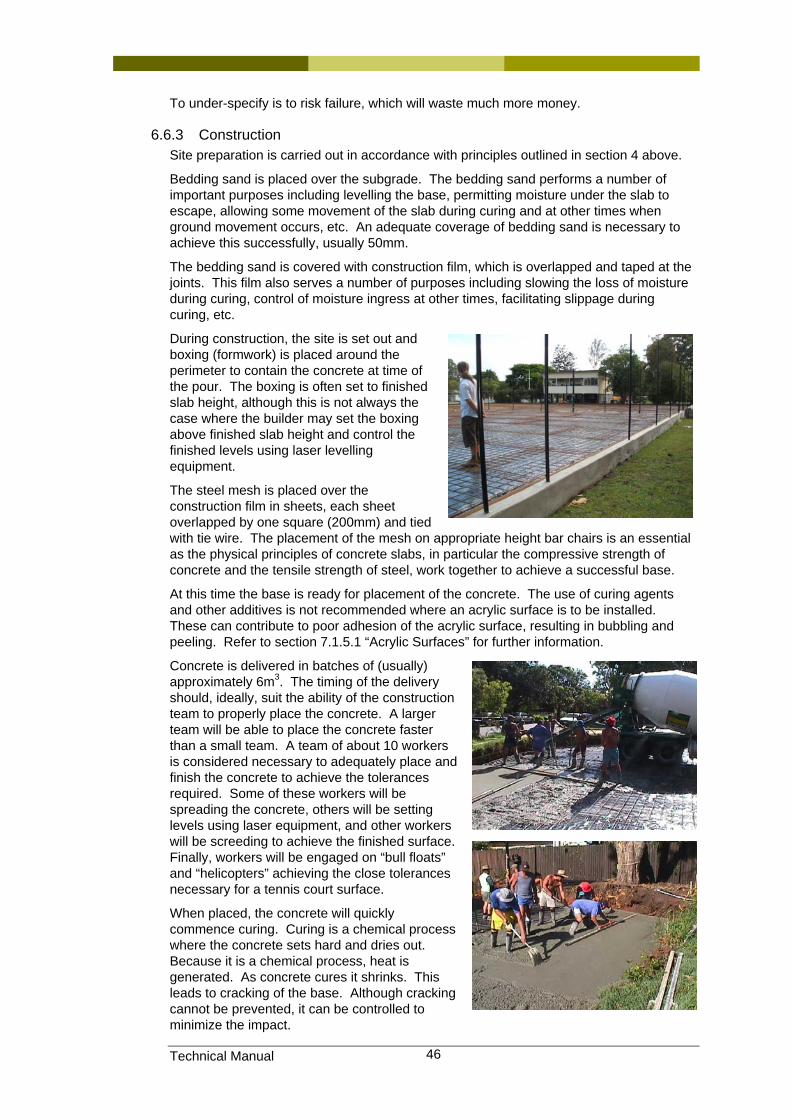
Technical Manual 46
To under-specify is to risk failure, which will waste much more money.
6.6.3 Construction Site preparation is carried out in accordance with principles outlined in section 4 above.
Bedding sand is placed over the subgrade. The bedding sand performs a number of important purposes including levelling the base, permitting moisture under the slab to escape, allowing some movement of the slab during curing and at other times when ground movement occurs, etc. An adequate coverage of bedding sand is necessary to achieve this successfully, usually 50mm.
The bedding sand is covered with construction film, which is overlapped and taped at the joints. This film also serves a number of purposes including slowing the loss of moisture during curing, control of moisture ingress at other times, facilitating slippage during curing, etc.
During construction, the site is set out and boxing (formwork) is placed around the perimeter to contain the concrete at time of the pour. The boxing is often set to finished slab height, although this is not always the case where the builder may set the boxing above finished slab height and control the finished levels using laser levelling equipment.
The steel mesh is placed over the construction film in sheets, each sheet overlapped by one square (200mm) and tied with tie wire. The placement of the mesh on appropriate height bar chairs is an essential as the physical principles of concrete slabs, in particular the compressive strength of concrete and the tensile strength of steel, work together to achieve a successful base.
At this time the base is ready for placement of the concrete. The use of curing agents and other additives is not recommended where an acrylic surface is to be installed. These can contribute to poor adhesion of the acrylic surface, resulting in bubbling and peeling. Refer to section 7.1.5.1 “Acrylic Surfaces” for further information.
Concrete is delivered in batches of (usually) approximately 6m3. The timing of the delivery should, ideally, suit the ability of the construction team to properly place the concrete. A larger team will be able to place the concrete faster than a small team. A team of about 10 workers is considered necessary to adequately place and finish the concrete to achieve the tolerances required. Some of these workers will be spreading the concrete, others will be setting levels using laser equipment, and other workers will be screeding to achieve the finished surface. Finally, workers will be engaged on “bull floats” and “helicopters” achieving the close tolerances necessary for a tennis court surface.
When placed, the concrete will quickly commence curing. Curing is a chemical process where the concrete sets hard and dries out. Because it is a chemical process, heat is generated. As concrete cures it shrinks. This leads to cracking of the base. Although cracking cannot be prevented, it can be controlled to minimize the impact.
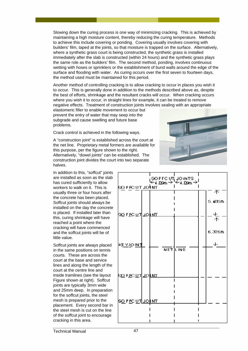
Technical Manual 47
Slowing down the curing process is one way of minimizing cracking. This is achieved by maintaining a high moisture content, thereby reducing the curing temperature. Methods to achieve this include covering or ponding. Covering usually involves covering with builders’ film, taped at the joints, so that moisture is trapped on the surface. Alternatively, where a synthetic grass court is being constructed, the synthetic grass is installed immediately after the slab is constructed (within 24 hours) and the synthetic grass plays the same role as the builders’ film. The second method, ponding, involves continuous wetting with hoses or sprinklers or the establishment of bund walls around the edge of the surface and flooding with water. As curing occurs over the first seven to fourteen days, the method used must be maintained for this period.
Another method of controlling cracking is to allow cracking to occur in places you wish it to occur. This is generally done in addition to the methods described above as, despite the best of efforts, shrinkage and the resultant cracks will occur. When cracking occurs where you wish it to occur, in straight lines for example, it can be treated to remove negative effects. Treatment of construction joints involves sealing with an appropriate elastomeric filler to enable movement to occur but prevent the entry of water that may seep into the subgrade and cause swelling and future base problems.
Crack control is achieved in the following ways.
A “construction joint” is established across the court at the net line. Proprietary metal formers are available for this purpose, per the figure shown to the right. Alternatively, “dowel joints” can be established. The construction joint divides the court into two separate halves.
In addition to this, “soffcut” joints are installed as soon as the slab has cured sufficiently to allow workers to walk on it. This is usually three or four hours after the concrete has been placed. Soffcut joints should always be installed on the day the concrete is placed. If installed later than this, curing shrinkage will have reached a point where the cracking will have commenced and the soffcut joints will be of little value.
Soffcut joints are always placed in the same positions on tennis courts. These are across the court at the base and service lines and along the length of the court at the centre line and inside tramlines (see the layout Figure shown at right). Soffcut joints are typically 3mm wide and 25mm deep. In preparation for the soffcut joints, the steel mesh is prepared prior to the placement. Every second bar in the steel mesh is cut on the line of the soffcut joint to encourage cracking in this area.
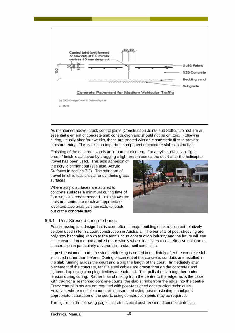
Technical Manual 48
As mentioned above, crack control joints (Construction Joints and Soffcut Joints) are an essential element of concrete slab construction and should not be omitted. Following curing, usually after four weeks, these are treated with an elastomeric filler to prevent moisture entry. This is also an important component of concrete slab construction.
Finishing of the concrete slab is an important element. For acrylic surfaces, a “light broom” finish is achieved by dragging a light broom across the court after the helicopter trowel has been used. This aids adhesion of the acrylic primer coat (see also, Acrylic Surfaces in section 7.2). The standard of trowel finish is less critical for synthetic grass surfaces.
Where acrylic surfaces are applied to concrete surfaces a minimum curing time of four weeks is recommended. This allows the moisture content to reach an appropriate level and also enables chemicals to leach out of the concrete slab.
6.6.4 Post Stressed concrete bases Post stressing is a design that is used often in major building construction but relatively seldom used in tennis court construction in Australia. The benefits of post-stressing are only now becoming known to the tennis court construction industry and the future will see this construction method applied more widely where it delivers a cost effective solution to construction in particularly adverse site and/or soil conditions.
In post tensioned courts the steel reinforcing is added immediately after the concrete slab is placed rather than before. During placement of the concrete, conduits are installed in the slab running across the court and along the length of the court. Immediately after placement of the concrete, tensile steel cables are drawn through the concretes and tightened up using clamping devices at each end. This pulls the slab together under tension during curing. Rather than shrinking from the centre to the edge, as is the case with traditional reinforced concrete courts, the slab shrinks from the edge into the centre. Crack control joints are not required with post-tensioned construction techniques. However, where multiple courts are constructed using post-tensioning techniques, appropriate separation of the courts using construction joints may be required.
The figure on the following page illustrates typical post-tensioned court slab details.
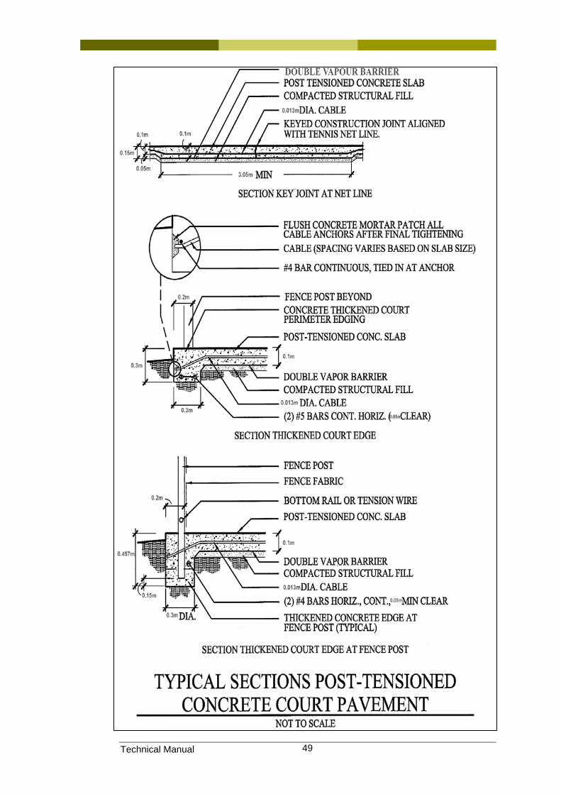
Technical Manual 49
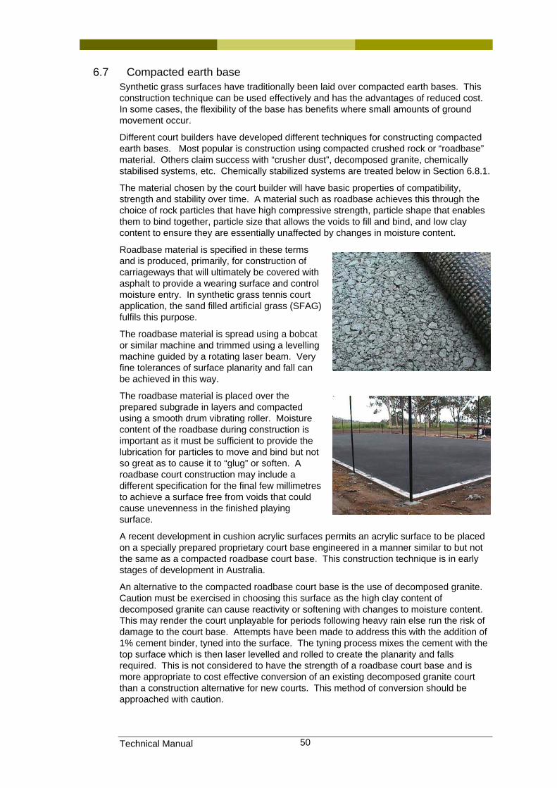
Technical Manual 50
6.7 Compacted earth base Synthetic grass surfaces have traditionally been laid over compacted earth bases. This construction technique can be used effectively and has the advantages of reduced cost. In some cases, the flexibility of the base has benefits where small amounts of ground movement occur.
Different court builders have developed different techniques for constructing compacted earth bases. Most popular is construction using compacted crushed rock or “roadbase” material. Others claim success with “crusher dust”, decomposed granite, chemically stabilised systems, etc. Chemically stabilized systems are treated below in Section 6.8.1.
The material chosen by the court builder will have basic properties of compatibility, strength and stability over time. A material such as roadbase achieves this through the choice of rock particles that have high compressive strength, particle shape that enables them to bind together, particle size that allows the voids to fill and bind, and low clay content to ensure they are essentially unaffected by changes in moisture content.
Roadbase material is specified in these terms and is produced, primarily, for construction of carriageways that will ultimately be covered with asphalt to provide a wearing surface and control moisture entry. In synthetic grass tennis court application, the sand filled artificial grass (SFAG) fulfils this purpose.
The roadbase material is spread using a bobcat or similar machine and trimmed using a levelling machine guided by a rotating laser beam. Very fine tolerances of surface planarity and fall can be achieved in this way.
The roadbase material is placed over the prepared subgrade in layers and compacted using a smooth drum vibrating roller. Moisture content of the roadbase during construction is important as it must be sufficient to provide the lubrication for particles to move and bind but not so great as to cause it to “glug” or soften. A roadbase court construction may include a different specification for the final few millimetres to achieve a surface free from voids that could cause unevenness in the finished playing surface.
A recent development in cushion acrylic surfaces permits an acrylic surface to be placed on a specially prepared proprietary court base engineered in a manner similar to but not the same as a compacted roadbase court base. This construction technique is in early stages of development in Australia.
An alternative to the compacted roadbase court base is the use of decomposed granite. Caution must be exercised in choosing this surface as the high clay content of decomposed granite can cause reactivity or softening with changes to moisture content. This may render the court unplayable for periods following heavy rain else run the risk of damage to the court base. Attempts have been made to address this with the addition of 1% cement binder, tyned into the surface. The tyning process mixes the cement with the top surface which is then laser levelled and rolled to create the planarity and falls required. This is not considered to have the strength of a roadbase court base and is more appropriate to cost effective conversion of an existing decomposed granite court than a construction alternative for new courts. This method of conversion should be approached with caution.
Technical Manual 51
Clay and decomposed granite court surfaces may be considered in this section of base construction as the base and surface form a single unit. However, these will be dealt with in the “Court Surfaces” discussions in Section 7 of this Manual.
6.8 Proprietary base systems
6.8.1 Chemically bound systems A number of court construction companies offer chemically bound compacted earth base structures. The base is usually constructed of imported material such as roadbase or crusher dust that is placed and compacted in the usual way. Occasionally sand is used.
The base is then sprayed with a chemical binder. The manufacturers claim the binder strengthens the base while permitting moisture to drain vertically through the base resulting in the synthetic grass surface drying out more quickly. One concern with this is that the moisture must then enter the subgrade and, should the court be built on reactive ground, could cause subgrade problems.
The strength of this base is still derived from the compacted material over which the spray is applied and the principles of sound compacted earth base construction must still be adhered to. This method of construction is not recommended for difficult ground conditions and caution is recommended if choosing this base construction method.
6.9 Maintenance and repair of base structure A regular, structured maintenance regime covering the surface and court surrounds is the most effective way to prolong the life of the court base. This is dealt with in Section 7 of this manual.
6.10 Information sources, Standards and Codes. A number of Australian Standards exist that cover Asphalt and Concrete platform construction and maintenance. The principles apply equally to tennis courts. This includes:
• Australian Standards AS 2870 and AS 3798
• CSIRO Guides, such as “Foundation Maintenance and Footing Performance: A Homeowner’s Guide”
• Australian Asphalt Paving Association Codes of Practice.
Acrylic surface manufacturers also publish technical information on court base construction suitable for their products.
The best method of obtaining correct information when designing a court base is via a qualified geotechnical engineer. A geotechnical engineer will test the subgrade conditions at the site and design a base structure that will provide the balance between economical construction and requirements due to potential ground movement. Throughout this manual, court owners will be encouraged to engage professional engineering assistance at the planning stage of court construction.
Technical Manual 52
7 Surface
7.1 Introduction
7.1.1 Definitions used in this section Acrylic Material used for surfacing courts that provides colour and texture
to the court surface.
Bird baths Depressions in the court surface that retain water following rain
Clean sweep Brand name of popular court grooming device consisting of a mat like structure that is dragged across the court. The device gathers leaves and other debris that can be disposed of away from the playing surface. The “Clean Sweep” also re-distributes the infill sand evenly across a synthetic grass surface.
Cushion acrylic Acrylic surface that includes cushion properties.
Expansion joints Construction joint that permits expansion/contraction of the court base.
“Mat lay” systems Cushion surface installed by rolling out preformed sheet cushion material that is jointed and coated with an acrylic surface.
Mud cracking Multiple cracks in a surface that resemble dried mud.
Pace A measurement of court characteristics that describes the speed and departure angle of the ball when it strikes the court surface.
Pot life The period of time that a chemical material lasts from mixing to application.
Rubber squeegee Device for spreading acrylic material over a court surface.
SFAG Sand Filled Artificial Grass.
Silica sand Sand made from silica that is used in synthetic grass tennis courts. Silica is preferred due to hardness and particle shape.
Speed A measure of court characteristics. See “Pace” above.
Synthetic grass Outdoor carpet product used in tennis court surfacing, so named because it is constructed and installed to resemble natural grass.
Tack Used to describe the behaviour of adhesives. A material with “tack” grips the products being joined during the curing process.
Viscosity Density of a liquid, measured by the ability of a material to flow through an aperture at a particular rate.
“Wet lay” systems Cushion acrylic surface where the cushion material is applied as a liquid and built up in layers until the desired thickness is achieved.
Windrow A row of (acrylic) material left by the action of the applicator with his/her squeegee.
7.1.2 Classification of surface systems Different court surface systems produce different playing characteristics. They produce different reactions to ball bounce and pace; provide different levels of grip to the players feet, etc. This results in quite different styles of play between surfaces. These differences result in different players being more successful on different surfaces.
7.1.3 Choice of surface In addition to this, the style of play on some surfaces, such as natural clay, result in longer rallies and the most successful players on these surfaces are those with a more
Technical Manual 53
tactical approach to the game. The Tennis Australia Player Development Committee has recognized this and recommends certain surface types for developing players for the international circuit. Clubs or individuals considering a surface for the development of promising junior players should contact Tennis Australia for further advice on this matter.
Clubs or associations should consider the advantages and disadvantages of each surface type when choosing to build or resurface their courts. The best test is to survey member preferences and build surfaces that the members like to play on. After all, the attraction and retention of members is the most important factor in the success of a club.
7.1.4 Advantages and disadvantages As mentioned above, a club with a focus on developing juniors may choose clay courts so that the tactical issues in winning rallies are developed. This comes at a price. The cost of maintaining clay courts is high relative to alternatives and is addressed elsewhere in this manual, in particular at Section 7.1.5.4.
The construction cost of decomposed granite courts made them attractive for some struggling clubs. Again, the disadvantage of decomposed granite courts is the maintenance, line marking etc. Although not as expensive as clay, decomposed granite courts require regular grooming, watering, rolling, line marking before play etc. This is extremely labour intensive and will test the resolve of club volunteers.
Low maintenance surfaces have been developed over a number of years. These include, among others, acrylic and synthetic grass surfaces. These surfaces still require routine maintenance but this is substantially less than other surfaces on the market.
A more recent development is the “artificial clay” surface. This is an outdoor carpet, similar in design to the outdoor carpet used for synthetic grass surfaces but built to a different specification and colour. The infill sand is also a different specification (and colour) to the synthetic grass surface. Synthetic clay surfaces requires more frequent grooming than acrylic or synthetic grass but advocates argue that this is more than offset by the surface characteristics during play.
Many older players prefer synthetic grass or clay to acrylic surfaces, arguing that it is more comfortable on the body and gentler on aging joints. If true, this is an equally sound argument for junior play, at the cost of skill development.
Cushion acrylic surfaces are also available. These look similar to a standard acrylic surface but have the inclusion of a cushion layer of between 3mm and 8mm providing vertical cushion to the players. Current thinking suggests that cushion thickness of between 3mm and 5mm provides the best surface for tennis.
Natural grass is an attractive surface to play on and has been popular in Australia over many years. The major disadvantage of natural grass is the necessity to prepare it for play. This may involve mowing, rolling and line marking. In addition to that, it requires regular watering, mowing, fertilizing, treatment for weeds, etc.
A more detailed comparison of the advantages and disadvantages of the different surfaces have not been included in this manual at this time. However, clubs are reminded that members have preferences and this is the most important issue when choosing a surface.
7.1.5 Maintenance issues A primary issue in the selection of a surface is maintenance. An example of the maintenance issues and costs follows.
7.1.5.1 Acrylic This is probably the least intensive in maintenance effort of all the court surfaces.
The court should be kept clean and free from debris that can scratch the surface underfoot or create a safety hazard.
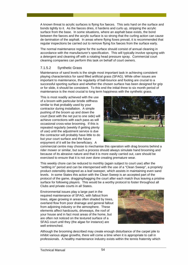
Technical Manual 54
A known threat to acrylic surfaces is flying fox faeces. This sets hard on the surface and bonds tightly to it. As the faeces dries, it hardens and curls up, stripping the acrylic surface from the base. In some situations, where an asphalt base exists, the bond between the faeces and the acrylic surface is so strong that the curling action can cause de-lamination of the asphalt. In areas where flying foxes prevail, it is recommended that regular inspections be carried out to remove flying fox faeces from the surface early.
The normal maintenance regime for the surface should consist of annual cleaning in accordance with the manufacturer’s specification. This will typically involve spraying with a detergent and cleaning off with a rotating head pressure spray. Commercial court cleaning companies can perform this task on behalf of court owners.
7.1.5.2 Synthetic Grass Maintenance of sand levels is the single most important task in achieving consistent playing characteristics for sand filled artificial grass (SFAG). While other issues are important to maintenance, the regularity of ball-bounce and footing are crucial to a successful sporting surface and whether the chosen surface has been designed for grip or for slide, it should be consistent. To this end the initial three to six month period of maintenance is the most crucial to long term happiness with the synthetic grass.
This is most readily achieved with the use of a broom with particular bristle stiffness similar to that probably used by your contractor during installation. A simple pushing of the broom up and down the court (best with the net put to one side) will achieve corrections with each pass as will occasional cross-wise brooming. If this is repeated regularly (weekly if getting plenty of use) until the adjustment service is due the contractor will probably have little to do but your court surface and the future enjoyment of it will be the beneficiary. A commercial centre may choose to mechanise this operation with drag brooms behind a rider mower or similar, but such a process should always simulate hand brooming and because of its abrasive nature and that it is more easily carried out, care should be exercised to ensure that it is not over done creating premature wear.
This weekly chore can be reduced to monthly (again subject to court use) after the “settling in” period and can be interspersed with the use of a “Clean Sweep”, a propriety product ostensibly designed as a leaf sweeper, which assists in maintaining even sand levels. In some States this action with the Clean Sweep is an accepted part of the protocol of the game, dragging/bagging the court after each match thus leaving a pristine surface for following players. This would be a worthy protocol to foster throughout all Clubs and private courts in all States.
Environmental issues play a large part in the required maintenance of SFAG, with fallout from trees, algae growing in areas often shaded by trees, overland flow from poor drainage and general fallout from adjoining industry or the atmosphere. These elements affect hardcourts, driveways, the roof of your house and in fact most areas of the home, but are often not noticed on the textured surface of a SFAG court until they (the algae for instance) are well entrenched.
Although the brooming described may create enough disturbance of the carpet pile to inhibit various algae growths, there will come a time when it is appropriate to call in professionals. A healthy maintenance industry exists within the tennis fraternity which
Technical Manual 55
can address all of the above provided that they always bear in mind the important issues that make SFAG successful.
Unless the carpet has been infiltrated by foreign matter it is rarely desirable to remove all of the sand from a SFAG surface as any areas so treated will need to go through the “settling in” period again. Most maintenance firms should be dealing with the top few millimetres of the surface and if removing sand with other polluted materials, care should be taken that the original sand levels are returned. They should also ensure that the treatments necessary on the side of a court do not assist in extending or spreading the problem across the full width of the court. Equally, cleaning of mechanical equipment after treatment at one address is important so that pollutants are not carried onto the next court to be serviced.
Treatment of infected areas by use of gurney or strong water jets should be carried out with caution so as to not remove an excess of sand which is difficult to replace consistently. Part of the apparent success of such an operation is emphasised by the as new “greenness” of the extra pile exposed below the top of the sand which can tend to mask any remaining algae growth. The use of blowers, although very efficient for leaf removal must be used with care as they too can remove some sand on each pass which in turn reduces the pile height and in turn the life of the carpet.
Chemical treatment of SFAG for algae growth has often been handled with the use of products such as copper sulphate or varying mixtures of pool chlorine and maintenance firms have their own proprietary anti-algae treatments. Such chemical treatments should only occur with the approval of the SFAG manufacturer who generally offers a seven year warranty on his product and great care should be exercised so that the general environment is not effected adversely.
Maintenance issues can be minimised by careful initial landscape planning through not planting inappropriate types of trees and not too close to the court (the root systems delight in ground conditions under SFAG) and the clearing of debris, leaf litter and any other infiltration. Good base construction through levels which shed water quickly, particularly in those areas shaded by trees or adjoining structures also assists in lowering of maintenance effort as will regular disturbance through sand levelling. A plastic lawn rake can make for hard work in clearing debris from the court but some solace may be taken in that the tips of the pile are being teased in a manner that assists the “settling in”.
The accepted norm for falls which allow good drainage of a court surface, whether SFAG or other non-porous synthetic surface types is 0.9% in both directions which on a minimum ITF court size of 34.77m x 17.10m will create falls of approximately 300mm in the length, 150mm in the width and 450mm from one corner to its diagonal opposite.
7.1.5.3 Synthetic Clay The care of synthetic clay is similar to the care for synthetic grass above. However, the particle size of the infill sand and the higher sand levels place some additional demands on the court during play.
The court should be bagged between sets and benefits from being watered periodically. Sand levels should be maintained.
7.1.5.4 Natural Clay Whilst this type of court can be economical to install, they will require significantly more ongoing maintenance (with associated costs) than hardcourt or artificial surfaces. Effective maintenance of natural clay is vital if the surface is to remain aesthetically pleasing, consistent in play, permeable to wet weather and long lasting.
Maintenance procedures are designed to ensure that:
• The playing surface is kept clean,
• The playing surface remains consistent to give a true and predictable game,
• Free drainage of surface water,
Technical Manual 56
• Looks attractive and well kept at all times.
These objectives are achieved by:
• Removal of surface plant debris and rubbish,
• Pulling a broom or drag mat over the surface between play,
• Keeping the surface moist by watering,
• Rolling periodically, especially after prolonged rain,
• Patching small wear depressions,
• Having surface damage repaired.
With clay courts, it is essential that an ongoing maintenance regime is adhered to, to ensure the consistency of the playing surface and the longevity of the court. Inadequate maintenance will significantly reduce the life of a clay playing surface.
By the very nature of the surface material, there is a tendency for compaction, wear and wind erosion. Therefore, part of the ongoing maintenance regime includes the rejuvenation of the surface by spreading new material to the affected areas, watering and rolling it. Some of this rejuvenation can be carried out by the court owner or club members after some initial supervision and guidance. Areas of heavy use (such as the baseline area) may require rebuilding once or twice over the service life of the court.
Providing the court drainage and foundation layers are in good condition, the surface can be scarified and new surface material spread, watered and rolled. Alternately, it may be necessary to undertake remedial work on the foundation layers. Where fixed (non chalk) lines are installed, it is probable that these lines will need to be replaced a number of times during the life of the court.
Given the recent introduction of severe water restrictions in many parts of Queensland and eastern Australia, the amount of watering these courts require to keep them in an acceptable condition is now a major issue with maintaining these types of surfaces. In the future, designated on site rainwater collection (i.e. via roof water collection) may be necessary to ensure the viability of such courts.
Clay surfaces, as with any surface, do not last forever. They have a finite life, which is dependent in part on their frequency of use and on how well they are maintained. In club situations, some of these substantial ongoing costs can be reduced by volunteer workers (if they can be found!). Along with the abovementioned periodic maintenance activities and repair works, owners should ultimately factor in the costs of rebuilding the clay surface every 10 to 20 years depending upon the maintenance regime employed.
Maintaining a large number of natural clay courts is best left to those with proven experience with such surfaces. Unfortunately, there are very few people with this ability in Australia and this should be taken into consideration prior to constructing or managing such courts.
7.1.5.5 Decomposed Granite Maintaining decomposed granite courts poses essentially the same issues as with clay court surfaces as discussed above, with the only major difference being the materials used for the final playing surface layer. To ensure the aesthetic and playability consistency of these courts throughout their serviceable life, a reasonable quantity of the original surfacing materials installed should be kept aside in storage for use during minor re-surfacing and patching maintenance works.
7.1.6 Playing characteristics The International Tennis Federation (ITF) has established a methodology for testing and classifying tennis court surfaces. The term used to describe the difference between the surfaces is “pace”. Laboratories accredited by the ITF carry out the testing in accordance with the strict guidelines of the methodology.
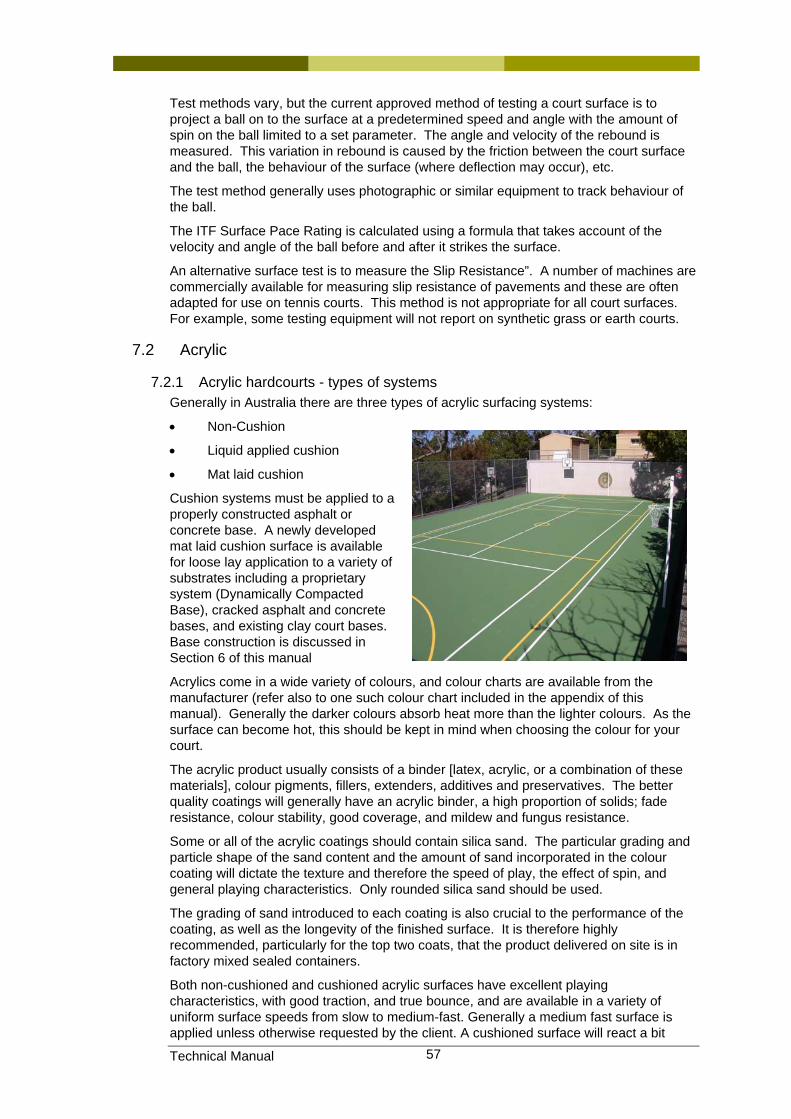
Technical Manual 57
Test methods vary, but the current approved method of testing a court surface is to project a ball on to the surface at a predetermined speed and angle with the amount of spin on the ball limited to a set parameter. The angle and velocity of the rebound is measured. This variation in rebound is caused by the friction between the court surface and the ball, the behaviour of the surface (where deflection may occur), etc.
The test method generally uses photographic or similar equipment to track behaviour of the ball.
The ITF Surface Pace Rating is calculated using a formula that takes account of the velocity and angle of the ball before and after it strikes the surface.
An alternative surface test is to measure the Slip Resistance”. A number of machines are commercially available for measuring slip resistance of pavements and these are often adapted for use on tennis courts. This method is not appropriate for all court surfaces. For example, some testing equipment will not report on synthetic grass or earth courts.
7.2 Acrylic
7.2.1 Acrylic hardcourts - types of systems Generally in Australia there are three types of acrylic surfacing systems:
• Non-Cushion
• Liquid applied cushion
• Mat laid cushion
Cushion systems must be applied to a properly constructed asphalt or concrete base. A newly developed mat laid cushion surface is available for loose lay application to a variety of substrates including a proprietary system (Dynamically Compacted Base), cracked asphalt and concrete bases, and existing clay court bases. Base construction is discussed in Section 6 of this manual
Acrylics come in a wide variety of colours, and colour charts are available from the manufacturer (refer also to one such colour chart included in the appendix of this manual). Generally the darker colours absorb heat more than the lighter colours. As the surface can become hot, this should be kept in mind when choosing the colour for your court.
The acrylic product usually consists of a binder [latex, acrylic, or a combination of these materials], colour pigments, fillers, extenders, additives and preservatives. The better quality coatings will generally have an acrylic binder, a high proportion of solids; fade resistance, colour stability, good coverage, and mildew and fungus resistance.
Some or all of the acrylic coatings should contain silica sand. The particular grading and particle shape of the sand content and the amount of sand incorporated in the colour coating will dictate the texture and therefore the speed of play, the effect of spin, and general playing characteristics. Only rounded silica sand should be used.
The grading of sand introduced to each coating is also crucial to the performance of the coating, as well as the longevity of the finished surface. It is therefore highly recommended, particularly for the top two coats, that the product delivered on site is in factory mixed sealed containers.
Both non-cushioned and cushioned acrylic surfaces have excellent playing characteristics, with good traction, and true bounce, and are available in a variety of uniform surface speeds from slow to medium-fast. Generally a medium fast surface is applied unless otherwise requested by the client. A cushioned surface will react a bit
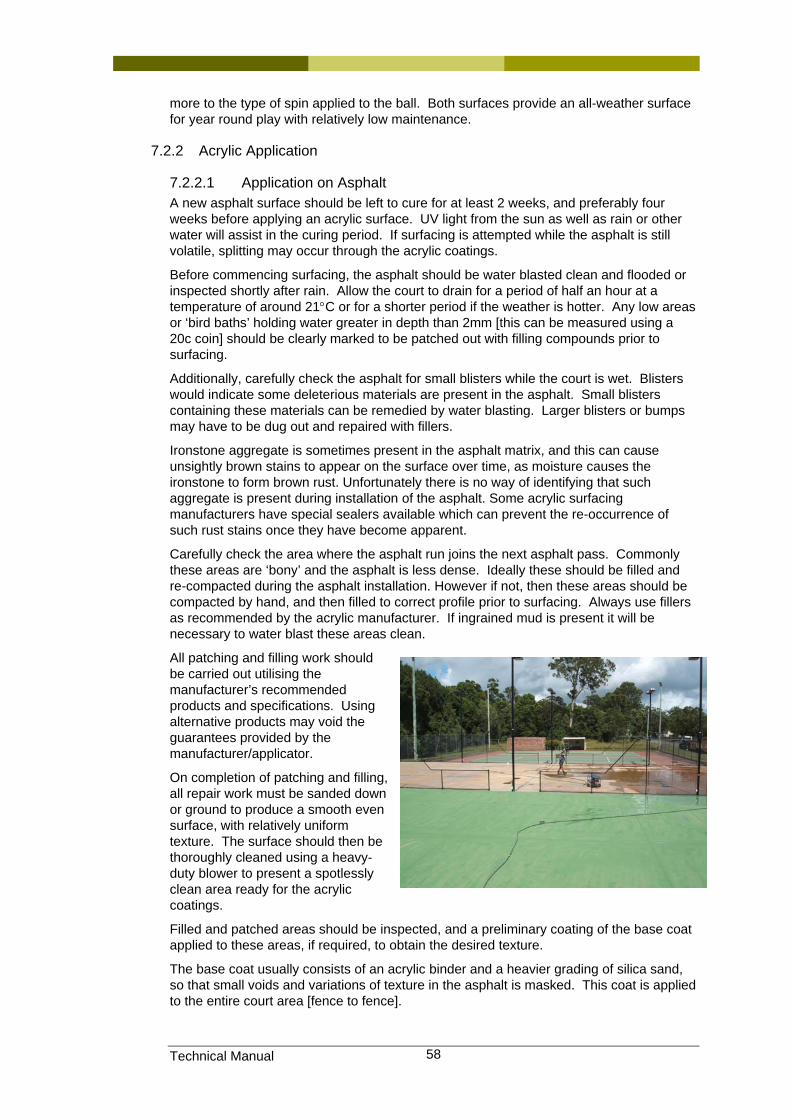
Technical Manual 58
more to the type of spin applied to the ball. Both surfaces provide an all-weather surface for year round play with relatively low maintenance.
7.2.2 Acrylic Application
7.2.2.1 Application on Asphalt A new asphalt surface should be left to cure for at least 2 weeks, and preferably four weeks before applying an acrylic surface. UV light from the sun as well as rain or other water will assist in the curing period. If surfacing is attempted while the asphalt is still volatile, splitting may occur through the acrylic coatings.
Before commencing surfacing, the asphalt should be water blasted clean and flooded or inspected shortly after rain. Allow the court to drain for a period of half an hour at a temperature of around 21°C or for a shorter period if the weather is hotter. Any low areas or ‘bird baths’ holding water greater in depth than 2mm [this can be measured using a 20c coin] should be clearly marked to be patched out with filling compounds prior to surfacing.
Additionally, carefully check the asphalt for small blisters while the court is wet. Blisters would indicate some deleterious materials are present in the asphalt. Small blisters containing these materials can be remedied by water blasting. Larger blisters or bumps may have to be dug out and repaired with fillers.
Ironstone aggregate is sometimes present in the asphalt matrix, and this can cause unsightly brown stains to appear on the surface over time, as moisture causes the ironstone to form brown rust. Unfortunately there is no way of identifying that such aggregate is present during installation of the asphalt. Some acrylic surfacing manufacturers have special sealers available which can prevent the re-occurrence of such rust stains once they have become apparent.
Carefully check the area where the asphalt run joins the next asphalt pass. Commonly these areas are ‘bony’ and the asphalt is less dense. Ideally these should be filled and re-compacted during the asphalt installation. However if not, then these areas should be compacted by hand, and then filled to correct profile prior to surfacing. Always use fillers as recommended by the acrylic manufacturer. If ingrained mud is present it will be necessary to water blast these areas clean.
All patching and filling work should be carried out utilising the manufacturer’s recommended products and specifications. Using alternative products may void the guarantees provided by the manufacturer/applicator.
On completion of patching and filling, all repair work must be sanded down or ground to produce a smooth even surface, with relatively uniform texture. The surface should then be thoroughly cleaned using a heavy-duty blower to present a spotlessly clean area ready for the acrylic coatings.
Filled and patched areas should be inspected, and a preliminary coating of the base coat applied to these areas, if required, to obtain the desired texture.
The base coat usually consists of an acrylic binder and a heavier grading of silica sand, so that small voids and variations of texture in the asphalt is masked. This coat is applied to the entire court area [fence to fence].
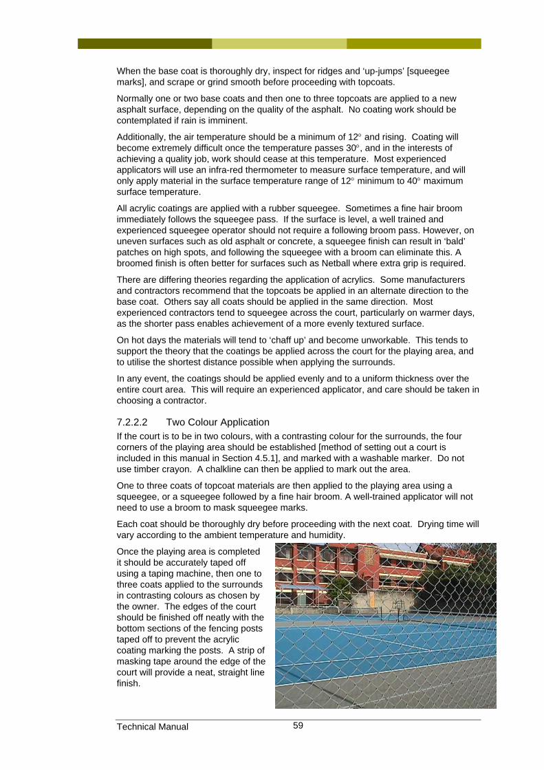
Technical Manual 59
When the base coat is thoroughly dry, inspect for ridges and ‘up-jumps’ [squeegee marks], and scrape or grind smooth before proceeding with topcoats.
Normally one or two base coats and then one to three topcoats are applied to a new asphalt surface, depending on the quality of the asphalt. No coating work should be contemplated if rain is imminent.
Additionally, the air temperature should be a minimum of 12° and rising. Coating will become extremely difficult once the temperature passes 30°, and in the interests of achieving a quality job, work should cease at this temperature. Most experienced applicators will use an infra-red thermometer to measure surface temperature, and will only apply material in the surface temperature range of 12° minimum to 40° maximum surface temperature.
All acrylic coatings are applied with a rubber squeegee. Sometimes a fine hair broom immediately follows the squeegee pass. If the surface is level, a well trained and experienced squeegee operator should not require a following broom pass. However, on uneven surfaces such as old asphalt or concrete, a squeegee finish can result in ‘bald’ patches on high spots, and following the squeegee with a broom can eliminate this. A broomed finish is often better for surfaces such as Netball where extra grip is required.
There are differing theories regarding the application of acrylics. Some manufacturers and contractors recommend that the topcoats be applied in an alternate direction to the base coat. Others say all coats should be applied in the same direction. Most experienced contractors tend to squeegee across the court, particularly on warmer days, as the shorter pass enables achievement of a more evenly textured surface.
On hot days the materials will tend to ‘chaff up’ and become unworkable. This tends to support the theory that the coatings be applied across the court for the playing area, and to utilise the shortest distance possible when applying the surrounds.
In any event, the coatings should be applied evenly and to a uniform thickness over the entire court area. This will require an experienced applicator, and care should be taken in choosing a contractor.
7.2.2.2 Two Colour Application If the court is to be in two colours, with a contrasting colour for the surrounds, the four corners of the playing area should be established [method of setting out a court is included in this manual in Section 4.5.1], and marked with a washable marker. Do not use timber crayon. A chalkline can then be applied to mark out the area.
One to three coats of topcoat materials are then applied to the playing area using a squeegee, or a squeegee followed by a fine hair broom. A well-trained applicator will not need to use a broom to mask squeegee marks.
Each coat should be thoroughly dry before proceeding with the next coat. Drying time will vary according to the ambient temperature and humidity.
Once the playing area is completed it should be accurately taped off using a taping machine, then one to three coats applied to the surrounds in contrasting colours as chosen by the owner. The edges of the court should be finished off neatly with the bottom sections of the fencing posts taped off to prevent the acrylic coating marking the posts. A strip of masking tape around the edge of the court will provide a neat, straight line finish.
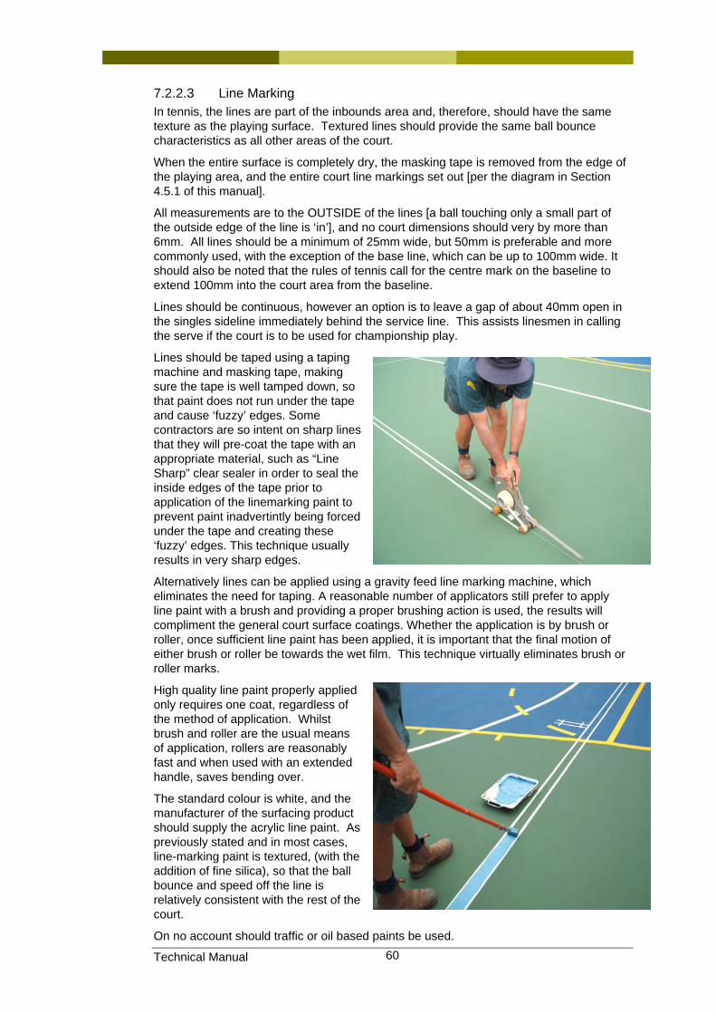
Technical Manual 60
7.2.2.3 Line Marking In tennis, the lines are part of the inbounds area and, therefore, should have the same texture as the playing surface. Textured lines should provide the same ball bounce characteristics as all other areas of the court.
When the entire surface is completely dry, the masking tape is removed from the edge of the playing area, and the entire court line markings set out [per the diagram in Section 4.5.1 of this manual].
All measurements are to the OUTSIDE of the lines [a ball touching only a small part of the outside edge of the line is ‘in’], and no court dimensions should very by more than 6mm. All lines should be a minimum of 25mm wide, but 50mm is preferable and more commonly used, with the exception of the base line, which can be up to 100mm wide. It should also be noted that the rules of tennis call for the centre mark on the baseline to extend 100mm into the court area from the baseline.
Lines should be continuous, however an option is to leave a gap of about 40mm open in the singles sideline immediately behind the service line. This assists linesmen in calling the serve if the court is to be used for championship play.
Lines should be taped using a taping machine and masking tape, making sure the tape is well tamped down, so that paint does not run under the tape and cause ‘fuzzy’ edges. Some contractors are so intent on sharp lines that they will pre-coat the tape with an appropriate material, such as “Line Sharp” clear sealer in order to seal the inside edges of the tape prior to application of the linemarking paint to prevent paint inadvertintly being forced under the tape and creating these ‘fuzzy’ edges. This technique usually results in very sharp edges.
Alternatively lines can be applied using a gravity feed line marking machine, which eliminates the need for taping. A reasonable number of applicators still prefer to apply line paint with a brush and providing a proper brushing action is used, the results will compliment the general court surface coatings. Whether the application is by brush or roller, once sufficient line paint has been applied, it is important that the final motion of either brush or roller be towards the wet film. This technique virtually eliminates brush or roller marks.
High quality line paint properly applied only requires one coat, regardless of the method of application. Whilst brush and roller are the usual means of application, rollers are reasonably fast and when used with an extended handle, saves bending over.
The standard colour is white, and the manufacturer of the surfacing product should supply the acrylic line paint. As previously stated and in most cases, line-marking paint is textured, (with the addition of fine silica), so that the ball bounce and speed off the line is relatively consistent with the rest of the court.
On no account should traffic or oil based paints be used.
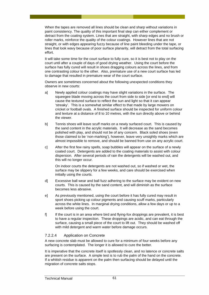
Technical Manual 61
When the tapes are removed all lines should be clean and sharp without variations in paint consistency. The quality of this important final step can either complement or detract from the coating system. Lines that are straight, with sharp edges and no brush or roller marks, reinforce the quality of the colour coatings. However lines that are not straight, or with edges appearing fuzzy because of line paint bleeding under the tape, or lines that look wavy because of poor surface planarity, will detract from the total surfacing effort.
It will take some time for the court surface to fully cure, so it is best not to play on the court until after a couple of days of good drying weather. Using the court before the surface has fully cured will result in shoes dragging colours across the lines, and from one contrasting colour to the other. Also, premature use of a new court surface has led to damage that resulted in premature wear of the court surface.
Owners are sometimes concerned about the following unexpected conditions they observe in new courts:
a] Newly applied colour coatings may have slight variations in the surface. The squeegee blade moving across the court from side to side [or end to end] will cause the textured surface to reflect the sun and light so that it can appear ‘streaky’. This is a somewhat similar effect to that made by large mowers on cricket or football ovals. A finished surface should be inspected for uniform colour and texture at a distance of 8 to 10 metres, with the sun directly above or behind the viewer.
b] Tennis shoes will leave scuff marks on a newly surfaced court. This is caused by the sand content in the acrylic materials. It will decrease as the sand becomes polished with play, and should not be of any concern. Black soled shoes (even those claimed to be ‘non-marking’), however, leave very unsightly marks which are almost impossible to remove, and should be banned from use on any acrylic court.
c] After the first few rainy spells, soap bubbles will appear on the surface of a newly coated court. Detergents are added to the coating materials to assist with colour dispersion. After several periods of rain the detergents will be washed out, and this will no longer occur.
On indoor courts the detergents are not washed out, so if washed or wet, the surface may be slippery for a few weeks, and care should be exercised when initially using the courts.
d] Excessive ball wear and ball fuzz adhering to the surface may be evident on new courts. This is caused by the sand content, and will diminish as the surface becomes less abrasive.
e] As previously mentioned, using the court before it has fully cured may result in sport shoes picking up colour pigments and causing scuff marks, particularly across the white lines. In marginal drying conditions, allow a few days or up to a week before using the court.
f] If the court is in an area where bird and flying-fox droppings are prevalent, it is best to have a regular inspection. These droppings are acidic, and can eat through the surface, causing a small piece of the court to lift out. They should be washed off with mild detergent and warm water before damage occurs.
7.2.2.4 Application on Concrete A new concrete slab must be allowed to cure for a minimum of four weeks before any surfacing is contemplated. The longer it is allowed to cure the better.
It is imperative that the concrete itself is spotlessly clean, and no latence or concrete salts are present on the surface. A simple test is to rub the palm of the hand on the concrete. If a whitish residue is apparent on the palm then surfacing should be delayed until the migration of concrete salts stops.
Technical Manual 62
Generally a concrete slab is treated with hydrochloric acid, using four parts water/one part acid solution, and then water blasted clean prior to any surface application. The surface should be thoroughly dry and clear of all concrete salts. All saw cut residues must be removed during the acid etch and water blasting treatment.
As with coating asphalt based courts, all depressions holding water should be patched to correct profile, utilising materials and methodologies recommended by the manufacturer, and any high spots removed by grinding with a concrete planer. Expansion joints [usually under the net line] should be filled with an elastomeric polyurethane joint-filler. To ensure a bond with the surfacing materials, some fine sand should be rubbed into the joint-filler surface prior to the curing process. Do not use acrylic caulking materials for expansion joints.
When patching is completed, a prime coat as recommended by the manufacturer should be applied to the entire court.
If a two-part epoxy primer is used, it is very important that the manufacturer’s specifications are closely adhered to. The first acrylic coating should be applied while the epoxy primer is still ‘tacky’ to touch. This will ensure a strong bond with the concrete base while still allowing a degree of vapour transmission from the slab.
Once the initial coating of acrylic has been applied, it is best to leave the surface overnight. The remaining two top coats can then be applied on the following day, given good drying conditions.
Line marking can then be completed in a similar fashion as described previously in Section 7.2.2.3.
7.2.3 Some dos and don’ts when coating acrylic tennis courts
7.2.3.1 Drying requirements It is important for the water in the coating to evaporate out of the mix within three to four hours after application. Water remaining in the film too long could affect uniformity of colour, adhesion, and sand retention. If temperature is at low end of operating scale, do not apply late in the afternoon.
7.2.3.2 Mixing and applying acrylic coating material If adding sand on site to a Colour Concentrate material, add the sand to the acrylic material prior to introducing water. However, a small amount of water may be needed to adjust the viscosity to reduce the load on the mixing equipment.
Factory mixed materials only require the addition of potable water on site.
Use a soft [flexible] rubber squeegee blade when applying textured colour coating. However, a stiff rubber blade may be used when fill coating.
Add material to the windrow in the lower half of the squeegee during application – i.e. the half closest to the applicator.
Follow adding to the windrow with the squeegee as soon as possible, and do not allow the windrow to dry out.
Mix (stir) the mixed materials just prior to using to keep the sand in suspension.
Wash all tools, squeegee blades and brooms as soon as possible. A wire brush is ideal for cleaning equipment.
Apply the coatings in a straight line. Eliminate circular motions even in restricted spaces such as between courts and/or behind baselines.
Apply the first two coats parallel to the net line [particularly in the play area].
Measure all mix ratios accurately.
Use textured line paint for tennis courts.
Technical Manual 63
7.2.3.3 Procedures to be avoided in applying acrylic coating material Do not apply coatings unless the surface temperature is 12°C and rising.
Do not apply coatings if the surface has been exposed to freezing temperatures the night before; i.e. allow the surface to rise to 12°C.
Do not apply material if surface temperature is above 40°C.
Do not apply subsequent coat until previous coat is completely dry. The interval between coats is related to the drying conditions. Heat and low humidity accelerate drying. Applying acrylic coatings during the night time hours of darkness is NOT recommended.
Do not apply acrylic coatings if the surface is wet.
Do not permit excessive material to remain in low spots on the final coat, otherwise these areas will mud-crack and shine.
Do not pull material more than 18metres in hot or windy conditions.
Do not play on court surface for the first 24 hours after completion – longer if temperatures are marginal.
7.2.3.4 Patching with a Recommended Patching Binder Perhaps the most neglected area of surfacing or resurfacing tennis courts is the identification and treatment of depressed areas that pond an excessive amount of water. Filling and levelling a depression is one thing, but doing it in such a manner that it does not reflect through the final coating takes experience and ‘know-how’. Patching is best performed by an experienced applicator.
The traditional method of locating ‘bird baths’ is to flood the surface, wait 15 minutes, and identify any depression that holds water deeper than the thickness of a 20c coin. At this point the area in question should be outlined with a marker to show how far the patch is to be applied.
Any depression approaching a depth of 6mm or more should be filled in with two or more applications of patch mix. On the first application, the deeper the depression, the larger the sand particle used in the mix. A deep depression should use a 30-60 mesh sand. The larger sand will make a stronger patch as well as minimise mud cracking. The second application should use the same sand as used in the filler coat mix. If only one application is used, it is better to use the same sand as the filler coat mix.
7.2.3.5 Area preparation On new courts it is necessary that the patch area be clean. New concrete surfaces should be acid treated prior to any patching. Once the patches are dry the court may then be primed with the manufacturer’s recommended product. On old courts it may be necessary to chemically clean the area with an algaecide.
On old courts it is recommended the area be tack-coated with a dilution of 2 parts water and 1 part binder. A good method of applying the tack-coat is to use a pump sprayer and mist a uniform film over the entire depressed area. Do not allow the material to puddle. The tack-coat should dry in 10 – 15 minutes and enhance adhesion. The area is now ready to be levelled.
7.2.3.6 Patching tools: The following tools are essential when patching court depressions:
• An aluminium or magnesium 2x4 metal screed long enough to bridge the depressed area, steel trowel, brush and pump spray.
• A disc sander, belt sander and rubbing stone are traditional items that can improve the quality of the patch.
Technical Manual 64
7.2.3.7 Mixing The most expedient method of mixing used by most contractors is to use an electric drill and stem mixer. If using an electric drill, it doesn’t matter what order the materials are blended together. An accepted practice is to mix the binder and cement, then add the sand. If mixing in a wheelbarrow or motor mixer, it is better to mix the dry sand and cement to prevent cement balls, and then add the binder.
NOTE: it may be necessary to add more binder to improve the workable consistency of the mix [do not add water to the mix].
7.2.3.8 Application of patching material Pour the mix at the edge of the marked depression and pull the metal screed across the low area, making certain no voids are left behind. If the viscosity of the mix is correct it will require a slow, steady pull of the metal screed straight edge, i.e. there is no need for a saw-cutting action. The metal screed should be held at an angle to the court surface so that the mix is forced down under the screed.
Once the body of the patch is acceptable, the edges are feathered to a fine edge using a steel trowel and brush.
NOTE: misting the patch surface with the water solution does not affect the mix, because the water is on the surface of the patch mix and evaporates quickly. However care should be taken to only apply a fine mist and not to leave any liquid solution lying on the screeded surface, otherwise skinning can occur, leaving the surface water sensitive and prone to later surface delamination.
7.2.3.9 Grinding patches Often properly installed patches do not require much grinding or sanding. However, if the planarity of the patch is not uniform and/or the edges are not properly feathered, it may become necessary to use a mechanical means to correct the condition. Minor problems may be corrected with a rubbing stone; however a disc or belt sander is fast and thorough.
As a final step in hiding patches, it may be helpful to pre-coat the patches with the filler coat mix.
7.2.3.10 Crack repairs One of the most difficult tasks a contractor faces when surfacing or resurfacing tennis courts is related to crack problems. It is relatively easy to fill cracks so that they do not reflect through subsequent coatings for a short period. A very risky situation exists, however, when one guarantees that cracks will not reappear over the longer term.
With few exceptions, cracks on outdoor surfaces are almost inevitable. The challenge is to keep the cracks to a minimum, and hope those cracks that do return will be minor in nature. In this case, minor means ‘hairline’ cracks, which do not affect the playability of the surface.
Whether construction materials are hot or cold mix asphalt, or concrete, any surface is subject to cracking. It appears that post-tensioned concrete courts experience the least amount of serious cracking. Furthermore, cracks that do appear only amount to hairline cracks because the tension on the cables keeps them closed.
There are three common causes of cracks:
1] Thermal expansion and contraction in which a surface reacts to rapid temperature changes
2] Shrinkage cracks which usually result from a volume change of the surface material soon after installation.
3] Structural cracks which are normally the result of subgrade failure.
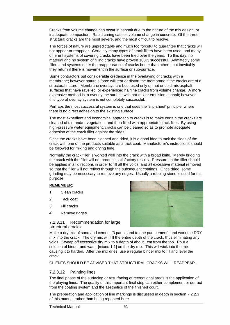
Technical Manual 65
Cracks from volume change can occur in asphalt due to the nature of the mix design, or inadequate compaction. Rapid curing causes volume change in concrete. Of the three, structural cracks are the most severe, and the most difficult to resolve.
The forces of nature are unpredictable and much too forceful to guarantee that cracks will not appear or reappear. Certainly many types of crack fillers have been used, and many different systems of covering cracks have been tried over the years. To this day, no material and no system of filling cracks have proven 100% successful. Admittedly some fillers and systems deter the reappearance of cracks better than others, but inevitably they return if there is movement in the surface or sub-surface.
Some contractors put considerable credence in the overlaying of cracks with a membrane; however nature’s force will tear or distort the membrane if the cracks are of a structural nature. Membrane overlays are best used only on hot or cold mix asphalt surfaces that have ravelled, or experienced hairline cracks from volume change. A more expensive method is to overlay the surface with hot-mix or emulsion asphalt; however this type of overlay system is not completely successful.
Perhaps the most successful system is one that uses the ‘slip-sheet’ principle, where there is no direct adhesion to the existing surface.
The most expedient and economical approach to cracks is to make certain the cracks are cleaned of dirt and/or vegetation, and then filled with appropriate crack filler. By using high-pressure water equipment, cracks can be cleaned so as to promote adequate adhesion of the crack filler against the sides.
Once the cracks have been cleaned and dried, it is a good idea to tack the sides of the crack with one of the products suitable as a tack coat. Manufacturer’s instructions should be followed for mixing and drying time.
Normally the crack filler is worked well into the crack with a broad knife. Merely bridging the crack with the filler will not produce satisfactory results. Pressure on the filler should be applied in all directions in order to fill all the voids, and all excessive material removed so that the filler will not reflect through the subsequent coatings. Once dried, some grinding may be necessary to remove any ridges. Usually a rubbing stone is used for this purpose.
REMEMBER:
1] Clean cracks
2] Tack coat
3] Fill cracks
4] Remove ridges
7.2.3.11 Recommendation for large structural cracks: Make a dry mix of sand and cement [3 parts sand to one part cement], and work the DRY mix into the crack. The dry mix will fill the entire depth of the crack, thus eliminating any voids. Sweep off excessive dry mix to a depth of about 1cm from the top. Pour a solution of binder and water [mixed 1:1] on the dry mix. This will wick into the mix causing it to harden. After the mix dries, use a regular binder mix to fill and level the crack.
CLIENTS SHOULD BE ADVISED THAT STRUCTURAL CRACKS WILL REAPPEAR.
7.2.3.12 Painting lines The final phase of the surfacing or resurfacing of recreational areas is the application of the playing lines. The quality of this important final step can either complement or detract from the coating system and the aesthetics of the finished court.
The preparation and application of line markings is discussed in depth in section 7.2.2.3 of this manual rather than being repeated here.
Technical Manual 66
REMEMBER: The rules of tennis require all lines shall be not less than 25mm wide, or more than 50mm in width, except the base line, which may be up to 100mm in width. It should also be noted that the rules call for the centre mark to be 100mm long.
In summary, it is important to install textured lines that are straight, with sharp edges and streak free (i.e. with no brush or roller marks).
7.2.3.13 Pouring windows All acrylic coatings tend to show a noticeable ‘streaking’ effect at the location where additional material has been added to the windrow.
As the windrow is moved along the surface, the percentage of water in the mix is reduced. This means the chemistry of the mix has been altered. When fresh material is added to the windrow it will contain a different percentage of water. Perhaps other chemicals as well may have been altered due to the surface temperature.
This problem is compounded when working on a hot surface. Consequently, it is always best to apply the final coat early in the morning while the surface is relatively cool.
Experience has shown that these pour marks can be made less conspicuous by -
1] Applying the final coat early in the morning or on a cool day, when the surface temperature is low
2] By pouring the fresh material on the wet acrylic film rather than on the dry or uncoated surface.
It is also a good idea to pour the material right behind the squeegee man while the acrylic film is as fresh [wet] as possible.
7.2.4 Cushion Acrylic
7.2.4.1 General Cushion acrylic surfaces appear, to the eye, similar to a standard acrylic hardcourt surface. However, these highly technical surfaces are ‘soft’ underfoot, providing cushioning to the foot fall so as to reduce fatigue and injury. Perhaps the best know of these surfaces in Australia are “Plexicushion” (the current Australian Open surface) and “Rebound Ace” (the previous Australian Open surface).
There are a small number of other cushion acrylic surfaces available in Australia, but little is known about the quality of these surfaces and the way in which they are being installed. The reason for this is there are very few recent examples of these surfaces, and even fewer have been made available for inspection and assessment by Tennis Queensland and/or Tennis Australia.
Cushion acrylic surfaces require installation over a sound base structure. Please refer to descriptions in Chapter 6 for details of asphalt and concrete base structures.
7.2.4.2 Base preparation Base tolerance for cushion surfaces is similar to that for standard acrylic hardcourts.
Planarity is reported by measuring the deviation beneath a 3m straight edge. The target is 3mm beneath the 3m straight edge placed anywhere on the surface. It should be remembered that the intention is to ensure that the court drains quickly following showers or storms and that the surface does not produce uneven bounce. The 3mm tolerance may be difficult to achieve on some bases, for example, asphalt.
Asphalt must be cured for a minimum of 14 days before installation of the cushion system. Concrete bases require longer curing times before application of the cushion acrylic surface.
Asphalt is cleaned by blasting with a high pressure water cleaner and must be free from all dust, dirt, grease etc. The surface must be thoroughly dry before application of the cushion system.
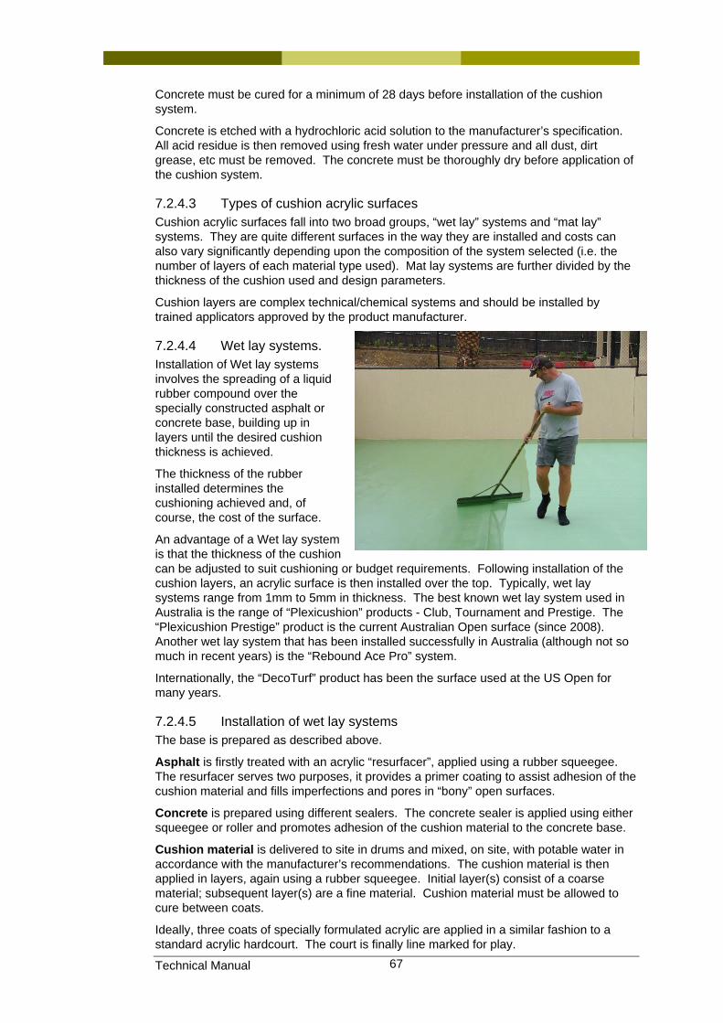
Technical Manual 67
Concrete must be cured for a minimum of 28 days before installation of the cushion system.
Concrete is etched with a hydrochloric acid solution to the manufacturer’s specification. All acid residue is then removed using fresh water under pressure and all dust, dirt grease, etc must be removed. The concrete must be thoroughly dry before application of the cushion system.
7.2.4.3 Types of cushion acrylic surfaces Cushion acrylic surfaces fall into two broad groups, “wet lay” systems and “mat lay” systems. They are quite different surfaces in the way they are installed and costs can also vary significantly depending upon the composition of the system selected (i.e. the number of layers of each material type used). Mat lay systems are further divided by the thickness of the cushion used and design parameters.
Cushion layers are complex technical/chemical systems and should be installed by trained applicators approved by the product manufacturer.
7.2.4.4 Wet lay systems. Installation of Wet lay systems involves the spreading of a liquid rubber compound over the specially constructed asphalt or concrete base, building up in layers until the desired cushion thickness is achieved.
The thickness of the rubber installed determines the cushioning achieved and, of course, the cost of the surface.
An advantage of a Wet lay system is that the thickness of the cushion can be adjusted to suit cushioning or budget requirements. Following installation of the cushion layers, an acrylic surface is then installed over the top. Typically, wet lay systems range from 1mm to 5mm in thickness. The best known wet lay system used in Australia is the range of “Plexicushion” products - Club, Tournament and Prestige. The “Plexicushion Prestige” product is the current Australian Open surface (since 2008). Another wet lay system that has been installed successfully in Australia (although not so much in recent years) is the “Rebound Ace Pro” system.
Internationally, the “DecoTurf” product has been the surface used at the US Open for many years.
7.2.4.5 Installation of wet lay systems The base is prepared as described above.
Asphalt is firstly treated with an acrylic “resurfacer”, applied using a rubber squeegee. The resurfacer serves two purposes, it provides a primer coating to assist adhesion of the cushion material and fills imperfections and pores in “bony” open surfaces.
Concrete is prepared using different sealers. The concrete sealer is applied using either squeegee or roller and promotes adhesion of the cushion material to the concrete base.
Cushion material is delivered to site in drums and mixed, on site, with potable water in accordance with the manufacturer’s recommendations. The cushion material is then applied in layers, again using a rubber squeegee. Initial layer(s) consist of a coarse material; subsequent layer(s) are a fine material. Cushion material must be allowed to cure between coats.
Ideally, three coats of specially formulated acrylic are applied in a similar fashion to a standard acrylic hardcourt. The court is finally line marked for play.
Technical Manual 68
7.2.4.6 Mat lay systems. The base is prepared as described above.
Asphalt is treated with an acrylic “resurfacer”, applied using a rubber squeegee. The resurfacer serves two purposes, it provides a primer coating to assist adhesion of the cushion material and fills imperfections and pores in “bony” open surfaces.
Concrete is prepared using different sealers to those specified for asphalt. The concrete sealer is applied using either squeegee or roller and enables adhesion of the cushion material to the concrete base.
Mat lay systems differ in that the cushion layer is delivered to site in pre manufactured rolls of predetermined thickness. These are rolled out and placed accurately in position with all edges tightly fitted, and then lifted and adhered to the surface using purpose developed adhesives. A significant feature of the adhesive is the lack of “tack”. This makes it difficult for the installer and it is most important that mat lay systems are installed by experience applicators trained and approved by the surface manufacturer.
Within the family of mat lay systems, several different types are in common use. The various mat lay systems currently available are generally supplied in either 4mm or 7mm cushion thickness.
7.2.4.7 Installation of mat lay systems Adhesives used for Mat lay courts consist of a two-part poly urethane system. The adhesive is mixed on site using mechanical mixers and has a limited “pot life”, that is, it must be used before it commences to ‘set’. This places demands on the surface installer in regard to quantities mixed, number of applicators on site, area covered with each mix, etc. As with all adhesives, application rates are critical.
Adhesive is applied to the dry, dust and grease free concrete using hand trowels and squeegees. Sealing of joins and court edges to prevent water ingress is a critical stage of installation.
When curing has been achieved, the mat is then sealed using a proprietary two-part polyurethane sealer that is also mixed on site. Great care is taken to ensure no imperfections exist on the surface. Any irregularities need to be ground off when the seal coat has cured.
Finishing varies depending on the system installed. Impact systems are sealed and then surfaced with the colour coats. Some systems are covered with an additional layer of reinforcing material prior to the application of the colour coats and line marking.
7.2.4.8 Maintenance of cushion acrylic surfaces It is important to follow manufacturers’ specifications for maintaining these highly technical surfaces.
In general terms, maintenance is similar to standard acrylic hardcourts. Restriction of marking-sole sports shoes is recommended. Maintenance of court surrounds, in particular drainage, avoidance of tree-root infestation, etc is recommended. These issues are covered in Section 4.6 in this manual.
Annual surface cleaning is recommended using a high pressure water cleaner. Use of a wand held above the court surface is safer than a rotating head cleaner as more control over the pressure applied to the surface is possible.
Bat droppings have a corrosive effect on acrylic surfaces and should be removed promptly where the courts are in close proximity to bat colonies.
Periodic renewal of the colour coat will be necessary and should be included in maintenance budgets for these and all sports surfaces. The surface installer will provide advice on anticipated court life given expected traffic. As a general rule, clubs should budget to recoat the surface every five years.
Technical Manual 69
7.2.5 Choice of colours for acrylic surfaces Acrylics come in a wide variety of colours, and colour charts are available from the manufacturer. Generally the darker colours absorb heat more than the lighters colours. As the surface can become hot, this should be kept in mind when choosing the colour for your court. Examples of the colours available can be found on many of the product manufacturer’s web sites.
7.2.6 Maintenance and repair of acrylic surfaces Refer to sections 7.1.5.1 and 7.2.4.8 above for maintenance requirements of acrylic and cushion acrylic court surfaces.
Refer to section 7.2.3 for information relating to the correct application and repair techniques with regards to acrylic court surfaces.
7.2.7 Resurfacing Before calling for quotations to resurface an existing acrylic surface, the owner should make a careful inspection of the court surface. A list of defects should be made and discussed with the contractor/s so that both parties are aware of the scope of works to be carried out. All the items to be attended should form part of the quotation. Generalised quotations simply stating “Repair existing surface and apply new acrylic coating” should not be contemplated.
Work to be carried out should be itemised in as much detail as possible. Quotations should also be accompanied by a copy of the manufacturer’s specification for the use and application of the product to be applied.
Decisions and directions taken regarding resurfacing an existing acrylic surface may include some or all of the following (Note: these items are only summarised here as they are each discussed in more detail in Section 7.2.3 and associated sub-sections):
Cleaning of existing surface. All mould and mildew must be killed and removed from the surface. Simply water blasting the mould will not eliminate all the spores, and new growth will occur within a short period of time. An appropriate algaecide must be applied to the entire area and then washed clean. The contractor shall be totally responsible for the collection and disposal of the waste products of this cleaning process.
Grinding back existing lines. All existing cracked, raised or glossy line marking paint should be ground back to the upper coating of the acrylic surface. If existing lines are level with the court surface and no build-up is apparent, then full removal of lines should not be necessary. It would be wise, however, to apply a wash coat to the lines prior to resurfacing to prevent the new product sliding across the polished lines.
Pressure cleaning. The entire surface should be pressure cleaned prior to applying any new product to the court surface. This pressure cleaning is prior to all patching work, filling of depressions, tack coating, etc. The contractor is to be responsible for appropriate disposal of all waste materials.
Delamination of surface. Pressure cleaning will reveal any weak spots or delamination in the existing surface. These areas may be ground back to remove all unstable product. Areas ground back are then bought back to the correct profile with the surrounding surface. The contractor should only use products recommended by the manufacturer of the acrylic coating to be applied. The patching materials should only be applied according to the manufacturer’s specification, which should be made available on request.
Areas holding water. The pressure cleaning will also reveal depressions that hold water. These are termed “bird baths”, and are defined as areas that after 15-20 minutes of drying are still holding water in excess of the thickness of a 20 cent coin at its deepest point. These areas are deemed to be unacceptable, and should be patched to correct the profile. This definition should be clearly understood by both client and contractor and areas to be treated agreed to by both parties. Depressions are identified and defined only with a washable marking chalk to avoid permanent marking of the surface. These are then patched to the correct profile using specific products as recommended and specified
Technical Manual 70
by the acrylic surfacing manufacturer. Deep depressions may require two or three applications of patching materials to correct the profile. Each application must dry thoroughly before proceeding to the next layer. Inadequate drying may result in “ghosting” of the patch appearing in the finished court surface.
Repairing cracks. Invariably most old court bases will have some degree of cracking that reflects through the surface. These can be defined as minor or major cracks.
Minor cracks are generally of a shallow depth and are due to the combined effects of shrinking and ageing of the base materials. As a guide, minor cracks and “alligator” crazing can often be successfully repaired with the use of fibreglass mesh or scrim. It must be accepted that over time, however, some evidence of cracking may again reflect through the surface materials.
Major cracks are of a structural nature mainly due to movement beneath the base. Typically such structural cracks are of appreciable depth, and may be full depth through the entire base construction. The treatment of cracks may vary from contractor to contractor. However, both client and contractor should have a clear understanding as to the scope of the work and the likely results. Due to their nature, major cracks will inevitably re-appear within a relatively short period of time. The only long term remedy with such cracking is to either rebuild or reconstruct the base after consultation with an engineer.
Clients should be made aware that not all cracking can be eliminated by a resurfacing procedure, and contractors should also make this clear in their quotations.
Workmanship for repairs. Depressions should first be tack coated to ensure proper adhesion of the patching materials. All patched should be feathered out at the edges so that no ridges are apparent. The patch should be sanded down so that the patch is blemish free. It is then advisable to apply one coat of base coat material over the patch to obtain a textures surface finish similar to the surrounding existing court surface. This procedure should be carried our prior to applying the first coating of resurfacing materials to the entire court.
Cracks should be thoroughly cleaned out, and all debris removed prior to any treatment. Major cracks should be treated by grinding out or using a V shaped chisel to compact and ‘V out’ the crack (asphalt only). All chiselling or grinding dust must then be removed from the crack. Crack filler or patching compound as recommended by the manufacturer can then be applied according to specifications. All crack filler materials should be thoroughly worked down into the crack. The materials should then be allowed to dry, and then ground off to correct court profile. All repair work should be pre-coated (as for depressions) prior to resurfacing.
Cleaning of surface. Once all repair work has been completed and the repair work pre-coated, the entire court surface should be cleaned with a heavy-duty air blower, combined with an operator using a hand scraper to thoroughly clean the court surface.
Application of new surface. Two or three coats [contractor should clearly specify in his quotation] of an approved tennis court surfacing product should then be applied strictly according to the manufacturer’s specifications. Mixing of the materials should take place on site, and immediately prior to commencing the resurfacing procedure.
Materials can be applied solely by a squeegee, or by squeegee followed by a fine hair broom, but should never be spread by broom only. It is preferable to keep the squeegee ‘runs’ as short as possible so that material does not ‘chaff up’ in hot weather. Each coat must be allowed to dry thoroughly prior to proceeding with the next coat. All work marks and minor blemishes must be scraped prior to a following coat.
Line Marking. Do not use airless spray equipment, as this will not provide a sharp edge on the lines. The court dimensions should be marked out according to the rules of tennis, and then, using a mechanical tape-laying machine, accurately place the longitudinal lines. The straightness of the lines should be checked and attended to if required. The tape should firmly adhere to the surface, and then the line-marking paint is applied by hand brush or roller.
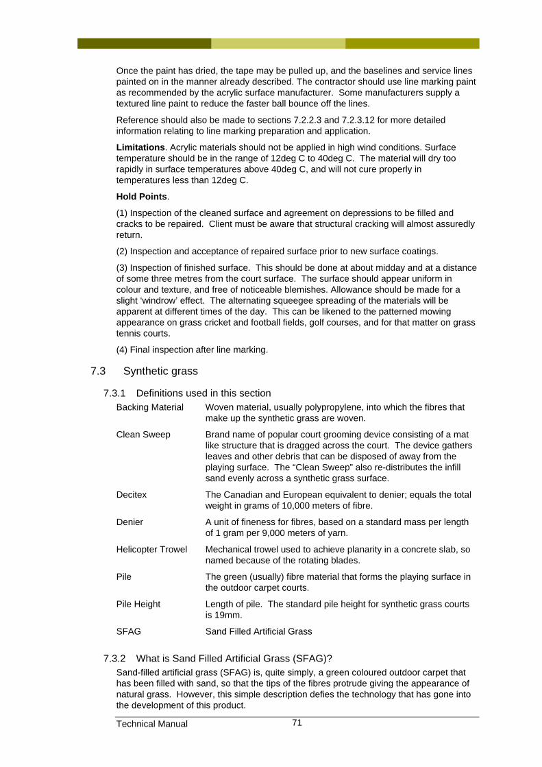
Technical Manual 71
Once the paint has dried, the tape may be pulled up, and the baselines and service lines painted on in the manner already described. The contractor should use line marking paint as recommended by the acrylic surface manufacturer. Some manufacturers supply a textured line paint to reduce the faster ball bounce off the lines.
Reference should also be made to sections 7.2.2.3 and 7.2.3.12 for more detailed information relating to line marking preparation and application.
Limitations. Acrylic materials should not be applied in high wind conditions. Surface temperature should be in the range of 12deg C to 40deg C. The material will dry too rapidly in surface temperatures above 40deg C, and will not cure properly in temperatures less than 12deg C.
Hold Points.
(1) Inspection of the cleaned surface and agreement on depressions to be filled and cracks to be repaired. Client must be aware that structural cracking will almost assuredly return.
(2) Inspection and acceptance of repaired surface prior to new surface coatings.
(3) Inspection of finished surface. This should be done at about midday and at a distance of some three metres from the court surface. The surface should appear uniform in colour and texture, and free of noticeable blemishes. Allowance should be made for a slight ‘windrow’ effect. The alternating squeegee spreading of the materials will be apparent at different times of the day. This can be likened to the patterned mowing appearance on grass cricket and football fields, golf courses, and for that matter on grass tennis courts.
(4) Final inspection after line marking.
7.3 Synthetic grass
7.3.1 Definitions used in this section Backing Material Woven material, usually polypropylene, into which the fibres that
make up the synthetic grass are woven.
Clean Sweep Brand name of popular court grooming device consisting of a mat like structure that is dragged across the court. The device gathers leaves and other debris that can be disposed of away from the playing surface. The “Clean Sweep” also re-distributes the infill sand evenly across a synthetic grass surface.
Decitex The Canadian and European equivalent to denier; equals the total weight in grams of 10,000 meters of fibre.
Denier A unit of fineness for fibres, based on a standard mass per length of 1 gram per 9,000 meters of yarn.
Helicopter Trowel Mechanical trowel used to achieve planarity in a concrete slab, so named because of the rotating blades.
Pile The green (usually) fibre material that forms the playing surface in the outdoor carpet courts.
Pile Height Length of pile. The standard pile height for synthetic grass courts is 19mm.
SFAG Sand Filled Artificial Grass
7.3.2 What is Sand Filled Artificial Grass (SFAG)? Sand-filled artificial grass (SFAG) is, quite simply, a green coloured outdoor carpet that has been filled with sand, so that the tips of the fibres protrude giving the appearance of natural grass. However, this simple description defies the technology that has gone into the development of this product.
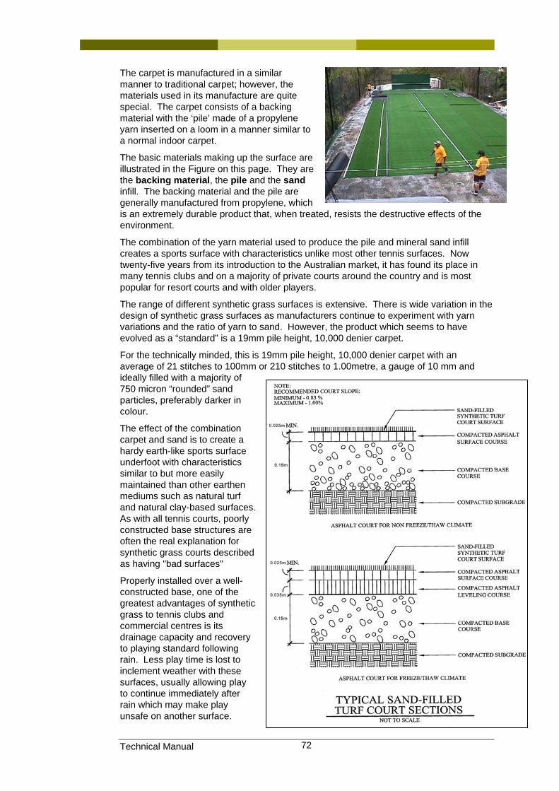
Technical Manual 72
The carpet is manufactured in a similar manner to traditional carpet; however, the materials used in its manufacture are quite special. The carpet consists of a backing material with the ‘pile’ made of a propylene yarn inserted on a loom in a manner similar to a normal indoor carpet.
The basic materials making up the surface are illustrated in the Figure on this page. They are the backing material, the pile and the sand infill. The backing material and the pile are generally manufactured from propylene, which is an extremely durable product that, when treated, resists the destructive effects of the environment.
The combination of the yarn material used to produce the pile and mineral sand infill creates a sports surface with characteristics unlike most other tennis surfaces. Now twenty-five years from its introduction to the Australian market, it has found its place in many tennis clubs and on a majority of private courts around the country and is most popular for resort courts and with older players.
The range of different synthetic grass surfaces is extensive. There is wide variation in the design of synthetic grass surfaces as manufacturers continue to experiment with yarn variations and the ratio of yarn to sand. However, the product which seems to have evolved as a “standard” is a 19mm pile height, 10,000 denier carpet.
For the technically minded, this is 19mm pile height, 10,000 denier carpet with an average of 21 stitches to 100mm or 210 stitches to 1.00metre, a gauge of 10 mm and ideally filled with a majority of 750 micron “rounded” sand particles, preferably darker in colour.
The effect of the combination carpet and sand is to create a hardy earth-like sports surface underfoot with characteristics similar to but more easily maintained than other earthen mediums such as natural turf and natural clay-based surfaces. As with all tennis courts, poorly constructed base structures are often the real explanation for synthetic grass courts described as having "bad surfaces"
Properly installed over a well-constructed base, one of the greatest advantages of synthetic grass to tennis clubs and commercial centres is its drainage capacity and recovery to playing standard following rain. Less play time is lost to inclement weather with these surfaces, usually allowing play to continue immediately after rain which may make play unsafe on another surface.
Technical Manual 73
7.3.3 Player preferences The tennis players’ preference for surfaces is too diverse to suggest any one surface as being “the best”. Surfaces such as synthetic grass, ant-bed or hardcourt are favoured by different players. Within the range of synthetic grass surfaces available, debate also occurs over which particular specification is the best. Individual preferences exist for grip or slide, hard or soft, high sand levels or low sand levels, ‘standard’ pile height or short pile, etc. Adding to this debate, the ball can often react quite differently from court to court due to the various surface textures of the different synthetic grasses available.
The choice of court surface, or mix of surfaces, often presents a difficulty for the decision makers who are planning a refurbishment or establishment of a new club. Traditionally, where club membership is made up of older or Veteran players the preferred surface is synthetic grass, often in conjunction with a road-base court platform. These players generally agree that the greater impact absorption and slide capacity of synthetic grass is kinder to aging joints. Adding to this is the advantage of less rain interrupted playing time and the extra club income gained from social bookings.
Ultimately, the choice of surface is best made by the users of the facility. A poll of court users, usually the club members, will lead to a surface choice that will keep membership levels healthy. Membership is the most important factor in the long term viability of a club. A choice made on cost alone will not best serve the long-term interests of the club.
The tennis construction industry offers a range of base and surface options to satisfy court owners’ preferences. Informed decisions result from thorough membership investigation that may include researching the experiences of other clubs, speaking with court builders and seeking advice from the State Tennis Association.
7.3.3.1 Surfaces for social play. Social players often prefer synthetic grass, based on the general ambiance, feel underfoot, comfort on the body, etc. The ability to recover following showers or storm is also attractive as it reduces the number of cancellations of the weekly bookings caused by rain.
7.3.3.2 Surfaces for competition and tournament play Synthetic grass is less preferred for competition play. At this point in time, Tennis Australia will not sanction any professional tournament or elite junior tournament on synthetic grass or synthetic clay surfaces. Hardcourts provide opportunities for a more tactical game where the court speed and foot grip encourage players to plan several strokes ahead of the winning shot. It is for this reason that Tennis Australia encourages the use of hardcourts for developing juniors as future champions. Conversely, synthetic grass properties encourage players to end a rally early.
Notwithstanding this, synthetic grass is very popular with clubs and is regularly used in club competitions around the country.
7.3.3.3 Compromises for club committees. The popularity of SFAG presents a difficult situation for tennis decision makers who are trying to encourage excellence in stroke making and court craft and require a surface that is consistent to teach these skills so as to keep pace with rapidly improving world talent. A large proportion of our emerging youth often gain their early experience from domestic and club synthetic grass courts but are quickly moved to hardcourts so that these skills can be honed. Further development of well advertised maintenance processes for SFAG courts is required so that these varying surface types can be complementary rather than adversarial.
7.3.4 Selecting a synthetic grass product. The choice of which synthetic grass best suits an application is difficult. The synthetic grass manufacturing industry offers such a wide choice in materials, many of which look very similar and it becomes difficult for even experienced judges to make an informed decision.
Technical Manual 74
Manufacturers are known to regularly alter the specification of their yarn and material suppliers creating inconsistencies with specification data for individual products from year to year. Tennis court building contractors who tend to be the intermediary of this information invariably claim valid reasons why the product they offer is superior to that of their competitors and thus it becomes very difficult for the buyer to make that properly informed decision.
Ideally, an objective durability test would predict the life span of a surface. Similarly, some form of “playability index” predicting the comfort for the players would assist. Unfortunately these objective measures are not available.
In the absence of a test for durability, the industry has chosen “face weight” as a measure of durability. Face weight is the weight of yarn that makes up the pile, measured from the top of the backing material to the tip of the pile. This measure works on the principle that the greater weight of yarn used, the better the product. This measure relies on the higher weight products lasting longer and assumes that each of the yarns being compared exhibit equal wear for a given mass. No objective measure exists for ‘playability”.
So, what is the correct choice? What makes one product superior to another? The answer is difficult given the small amount of data collected to date and the lack of records kept on individual court usage. Perhaps it is most appropriate for the buyer to deal only with manufacturers and contractors who have a proven track record and reputation as assurance of gaining the products and warranties necessary to long term satisfaction.
7.3.4.1 Pile height Synthetic grass is manufactured in a range of pile heights. Most common are12mm, 16mm, 19mm, 22mm, 34mm. Others may be manufactured from time to time.
Just as in yarn denier (or Decitex) and stitch rate, pile height is also often varied to suit different sports, or to arrive at a product with alternate tennis playing attributes. One such product is now produced by most manufacturers and features a lower 16mm pile height often with a lower denier (Decitex) yarn but a much increased stitch rate. Properly installed, the result is a surface which is much greener in appearance since less sand is visible and which features a more certain foot grip more often associated with hardcourts. However, the all important sand content and its ratio to the yarn, along with refined installation techniques remain crucial to production of a successful tennis surface.
7.3.4.2 Yarn varieties “Yarn” describes the material that comprises the fibres that give synthetic grass its appearance.
Polypropylene is the yarn that has been most successful to date for Tennis with nylon enjoying pride of place for many years for the sports of Field Hockey and American Football, while the use of polyethylene is popular for Soccer. The introduction of polyethylene yarn into Tennis products highlights the ongoing development by the industry and manufacturers looking for an edge. This success of trials using different yarns has been mixed.
7.3.4.3 Settling in time The majority of SFAG sports surfaces will require a period of time to “settle in” before arriving at a point where they can be considered to be playing at their best. This time period can vary from 3 months to 18 months subject firstly to the method of and care in installation of both synthetic grass and sand infill and secondly to the amount of play it receives. Usually more use is best. The third and probably most important factor in achieving excellence in the playing surface is maintenance. A simple brooming and bagging regime can not only accelerate this “settled in” status but will create a consistency in playing characteristics that will satisfy the toughest critic.
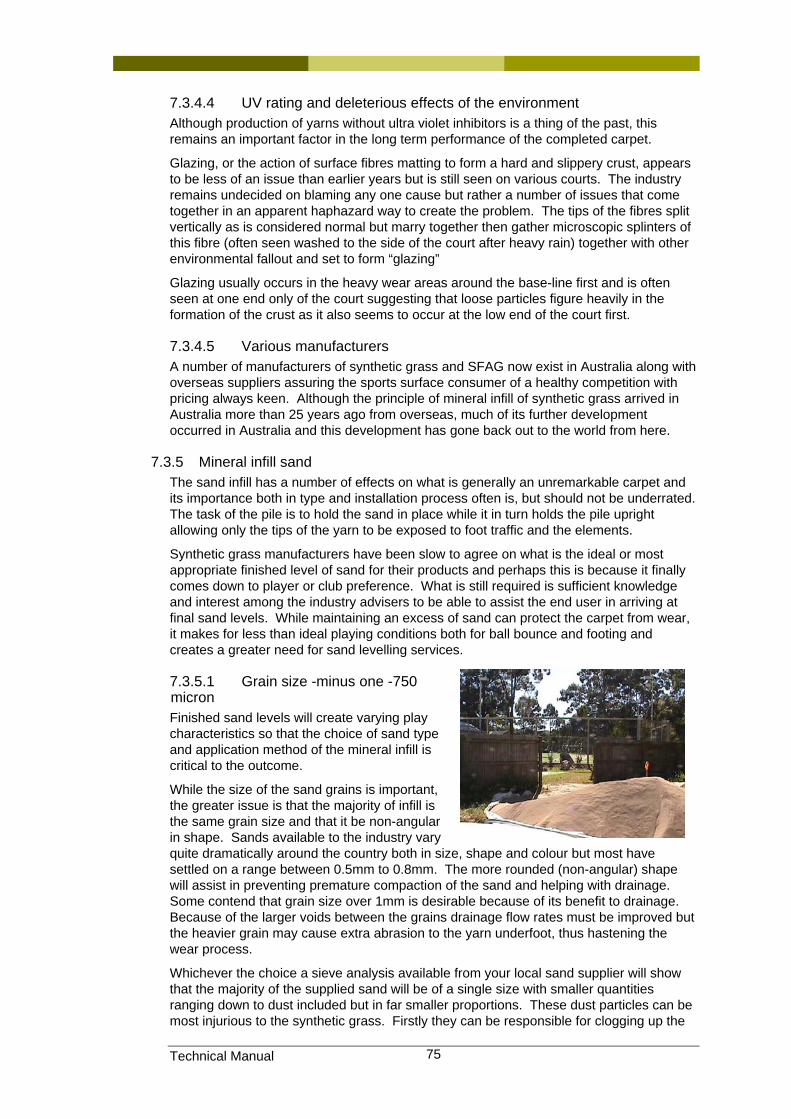
Technical Manual 75
7.3.4.4 UV rating and deleterious effects of the environment Although production of yarns without ultra violet inhibitors is a thing of the past, this remains an important factor in the long term performance of the completed carpet.
Glazing, or the action of surface fibres matting to form a hard and slippery crust, appears to be less of an issue than earlier years but is still seen on various courts. The industry remains undecided on blaming any one cause but rather a number of issues that come together in an apparent haphazard way to create the problem. The tips of the fibres split vertically as is considered normal but marry together then gather microscopic splinters of this fibre (often seen washed to the side of the court after heavy rain) together with other environmental fallout and set to form “glazing”
Glazing usually occurs in the heavy wear areas around the base-line first and is often seen at one end only of the court suggesting that loose particles figure heavily in the formation of the crust as it also seems to occur at the low end of the court first.
7.3.4.5 Various manufacturers A number of manufacturers of synthetic grass and SFAG now exist in Australia along with overseas suppliers assuring the sports surface consumer of a healthy competition with pricing always keen. Although the principle of mineral infill of synthetic grass arrived in Australia more than 25 years ago from overseas, much of its further development occurred in Australia and this development has gone back out to the world from here.
7.3.5 Mineral infill sand The sand infill has a number of effects on what is generally an unremarkable carpet and its importance both in type and installation process often is, but should not be underrated. The task of the pile is to hold the sand in place while it in turn holds the pile upright allowing only the tips of the yarn to be exposed to foot traffic and the elements.
Synthetic grass manufacturers have been slow to agree on what is the ideal or most appropriate finished level of sand for their products and perhaps this is because it finally comes down to player or club preference. What is still required is sufficient knowledge and interest among the industry advisers to be able to assist the end user in arriving at final sand levels. While maintaining an excess of sand can protect the carpet from wear, it makes for less than ideal playing conditions both for ball bounce and footing and creates a greater need for sand levelling services.
7.3.5.1 Grain size -minus one -750 micron Finished sand levels will create varying play characteristics so that the choice of sand type and application method of the mineral infill is critical to the outcome.
While the size of the sand grains is important, the greater issue is that the majority of infill is the same grain size and that it be non-angular in shape. Sands available to the industry vary quite dramatically around the country both in size, shape and colour but most have settled on a range between 0.5mm to 0.8mm. The more rounded (non-angular) shape will assist in preventing premature compaction of the sand and helping with drainage. Some contend that grain size over 1mm is desirable because of its benefit to drainage. Because of the larger voids between the grains drainage flow rates must be improved but the heavier grain may cause extra abrasion to the yarn underfoot, thus hastening the wear process.
Whichever the choice a sieve analysis available from your local sand supplier will show that the majority of the supplied sand will be of a single size with smaller quantities ranging down to dust included but in far smaller proportions. These dust particles can be most injurious to the synthetic grass. Firstly they can be responsible for clogging up the
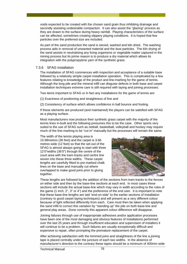
Technical Manual 76
voids expected to be created with the chosen sand grain thus inhibiting drainage and secondly assisting undesirable compaction. It can also assist the “glazing” process as they are drawn to the surface during heavy rainfall. Playing characteristics of the surface can be affected, sometimes creating slippery playing conditions. It is hoped that few particles over the preferred size are included.
As part of the sand production the sand is sieved, washed and kiln dried. The washing process aids in removal of unwanted material and the dust particles. The kiln drying of the sand assists in neutralising any living organisms or vegetable matter captured in the mining process but its prime reason is to produce a dry material which allows its integration with the polypropylene yarn of the synthetic grass.
7.3.6 SFAG installation The installation of SFAG commences with inspection and acceptance of a suitable base followed by a relatively simple carpet installation operation. This is complicated by a few features relating to knowledge of the product and line-marking for the game of tennis. Although the long pile and the mineral infill can disguise defects in both base and carpet installation techniques extreme care is still required with laying and joining processes.
Two items important to SFAG or in fact any installations for the game of tennis are:
(1) Exactness of positioning and straightness of line and
(2) Consistency of surface which allows confidence in ball bounce and footing.
If these elements are produced (and maintained) the players can be satisfied with SFAG as a playing surface.
Most manufacturers now produce their synthetic grass carpet with the majority of the tennis lines in-built and the following presumes this to be the case. Other sports very suited to the use of SFAG such as netball, basketball, volleyball and hockey may require much of the line-marking to be “cut in” manually but the processes will remain the same.
The width of the tennis playing area is 10.98metres (36 feet) and the carpet is 3.66 metres wide (12 feet) so that the set-out of the SFAG is almost always going to start with three 12’0”widths (36’0”) through the centre of the court area with the tram-tracks and centre line woven into these three widths. These carpet lengths are carefully fitted to pre-marked chalk lines on the base and manually cut where overlapped to make good joins prior to gluing together.
These lengths are followed by the addition of the sections from tram-tracks to the fences on either side and then by the base-line sections at each end. In most cases these sections will include the actual base-line which may vary in width according to the rules of the game (1 inch, 2”, 3” or 4”) and the preference of the end user. It is important to note that these base-line lengths are laid “end-on-side” to the earlier sections of installation (contrary to good carpet laying techniques) and will present as a very different colour because of light reflected differently from each. Care must then be taken when applying the sand infill to correct this variation by “standing up” the pile on both base-line and general play areas. Done correctly this apparent colour difference will disappear.
Joining failures through use of inappropriate adhesives and/or application processes have been one of the most damaging and obvious features of installations performed over the last 25 years and through insufficient education and supervision of installers it will continue to be a problem. Such failures are usually exceptionally difficult and expensive to repair, often prompting the premature replacement of the carpet.
After achieving satisfaction with the trimmed joins and straightness of the line a joining tape is placed centrally under the juncture of each two widths. In the absence of manufacturer’s direction to the contrary these tapes should be a minimum of 400mm wide
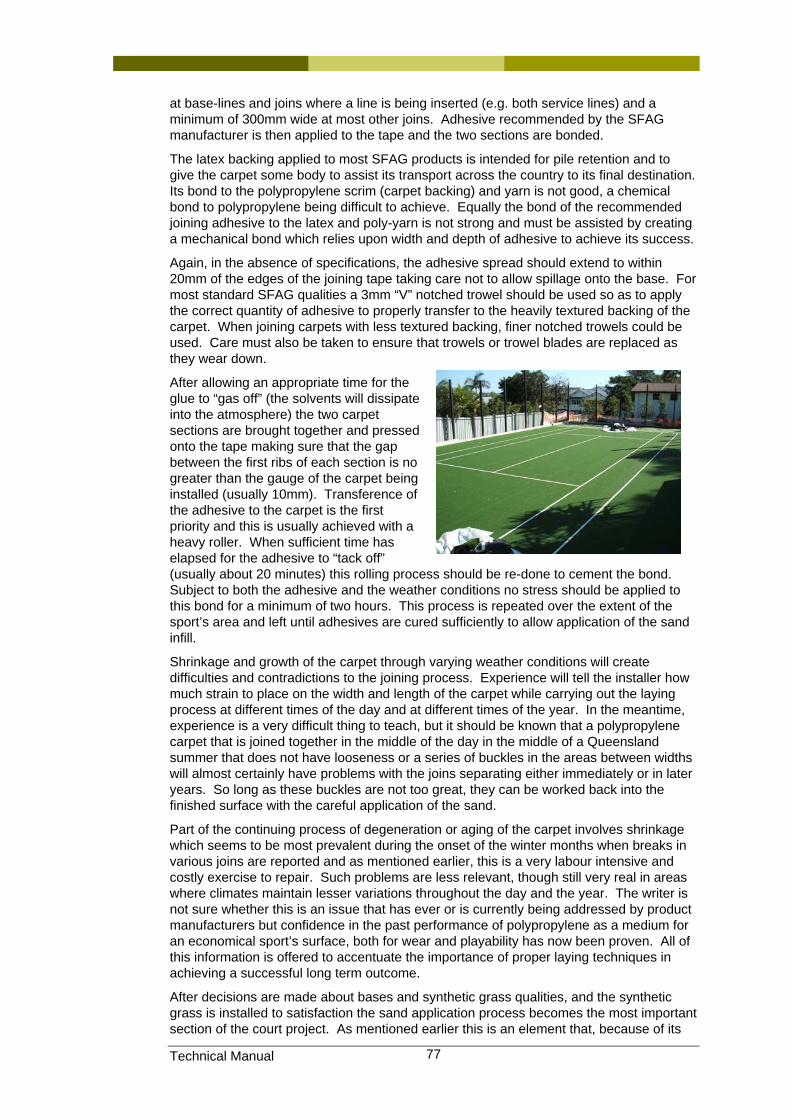
Technical Manual 77
at base-lines and joins where a line is being inserted (e.g. both service lines) and a minimum of 300mm wide at most other joins. Adhesive recommended by the SFAG manufacturer is then applied to the tape and the two sections are bonded.
The latex backing applied to most SFAG products is intended for pile retention and to give the carpet some body to assist its transport across the country to its final destination. Its bond to the polypropylene scrim (carpet backing) and yarn is not good, a chemical bond to polypropylene being difficult to achieve. Equally the bond of the recommended joining adhesive to the latex and poly-yarn is not strong and must be assisted by creating a mechanical bond which relies upon width and depth of adhesive to achieve its success.
Again, in the absence of specifications, the adhesive spread should extend to within 20mm of the edges of the joining tape taking care not to allow spillage onto the base. For most standard SFAG qualities a 3mm “V” notched trowel should be used so as to apply the correct quantity of adhesive to properly transfer to the heavily textured backing of the carpet. When joining carpets with less textured backing, finer notched trowels could be used. Care must also be taken to ensure that trowels or trowel blades are replaced as they wear down.
After allowing an appropriate time for the glue to “gas off” (the solvents will dissipate into the atmosphere) the two carpet sections are brought together and pressed onto the tape making sure that the gap between the first ribs of each section is no greater than the gauge of the carpet being installed (usually 10mm). Transference of the adhesive to the carpet is the first priority and this is usually achieved with a heavy roller. When sufficient time has elapsed for the adhesive to “tack off” (usually about 20 minutes) this rolling process should be re-done to cement the bond. Subject to both the adhesive and the weather conditions no stress should be applied to this bond for a minimum of two hours. This process is repeated over the extent of the sport’s area and left until adhesives are cured sufficiently to allow application of the sand infill.
Shrinkage and growth of the carpet through varying weather conditions will create difficulties and contradictions to the joining process. Experience will tell the installer how much strain to place on the width and length of the carpet while carrying out the laying process at different times of the day and at different times of the year. In the meantime, experience is a very difficult thing to teach, but it should be known that a polypropylene carpet that is joined together in the middle of the day in the middle of a Queensland summer that does not have looseness or a series of buckles in the areas between widths will almost certainly have problems with the joins separating either immediately or in later years. So long as these buckles are not too great, they can be worked back into the finished surface with the careful application of the sand.
Part of the continuing process of degeneration or aging of the carpet involves shrinkage which seems to be most prevalent during the onset of the winter months when breaks in various joins are reported and as mentioned earlier, this is a very labour intensive and costly exercise to repair. Such problems are less relevant, though still very real in areas where climates maintain lesser variations throughout the day and the year. The writer is not sure whether this is an issue that has ever or is currently being addressed by product manufacturers but confidence in the past performance of polypropylene as a medium for an economical sport’s surface, both for wear and playability has now been proven. All of this information is offered to accentuate the importance of proper laying techniques in achieving a successful long term outcome.
After decisions are made about bases and synthetic grass qualities, and the synthetic grass is installed to satisfaction the sand application process becomes the most important section of the court project. As mentioned earlier this is an element that, because of its
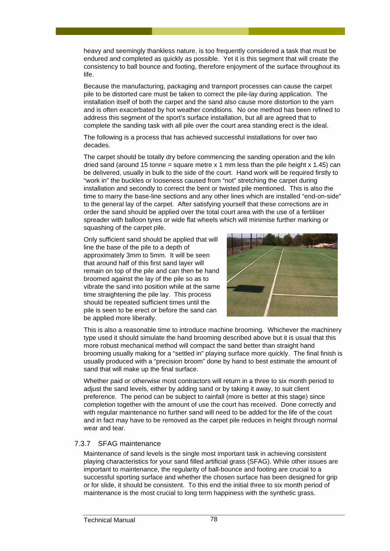
Technical Manual 78
heavy and seemingly thankless nature, is too frequently considered a task that must be endured and completed as quickly as possible. Yet it is this segment that will create the consistency to ball bounce and footing, therefore enjoyment of the surface throughout its life.
Because the manufacturing, packaging and transport processes can cause the carpet pile to be distorted care must be taken to correct the pile-lay during application. The installation itself of both the carpet and the sand also cause more distortion to the yarn and is often exacerbated by hot weather conditions. No one method has been refined to address this segment of the sport’s surface installation, but all are agreed that to complete the sanding task with all pile over the court area standing erect is the ideal.
The following is a process that has achieved successful installations for over two decades.
The carpet should be totally dry before commencing the sanding operation and the kiln dried sand (around 15 tonne = square metre x 1 mm less than the pile height x 1.45) can be delivered, usually in bulk to the side of the court. Hand work will be required firstly to “work in” the buckles or looseness caused from “not” stretching the carpet during installation and secondly to correct the bent or twisted pile mentioned. This is also the time to marry the base-line sections and any other lines which are installed “end-on-side” to the general lay of the carpet. After satisfying yourself that these corrections are in order the sand should be applied over the total court area with the use of a fertiliser spreader with balloon tyres or wide flat wheels which will minimise further marking or squashing of the carpet pile.
Only sufficient sand should be applied that will line the base of the pile to a depth of approximately 3mm to 5mm. It will be seen that around half of this first sand layer will remain on top of the pile and can then be hand broomed against the lay of the pile so as to vibrate the sand into position while at the same time straightening the pile lay. This process should be repeated sufficient times until the pile is seen to be erect or before the sand can be applied more liberally.
This is also a reasonable time to introduce machine brooming. Whichever the machinery type used it should simulate the hand brooming described above but it is usual that this more robust mechanical method will compact the sand better than straight hand brooming usually making for a “settled in” playing surface more quickly. The final finish is usually produced with a “precision broom” done by hand to best estimate the amount of sand that will make up the final surface.
Whether paid or otherwise most contractors will return in a three to six month period to adjust the sand levels, either by adding sand or by taking it away, to suit client preference. The period can be subject to rainfall (more is better at this stage) since completion together with the amount of use the court has received. Done correctly and with regular maintenance no further sand will need to be added for the life of the court and in fact may have to be removed as the carpet pile reduces in height through normal wear and tear.
7.3.7 SFAG maintenance Maintenance of sand levels is the single most important task in achieving consistent playing characteristics for your sand filled artificial grass (SFAG). While other issues are important to maintenance, the regularity of ball-bounce and footing are crucial to a successful sporting surface and whether the chosen surface has been designed for grip or for slide, it should be consistent. To this end the initial three to six month period of maintenance is the most crucial to long term happiness with the synthetic grass.
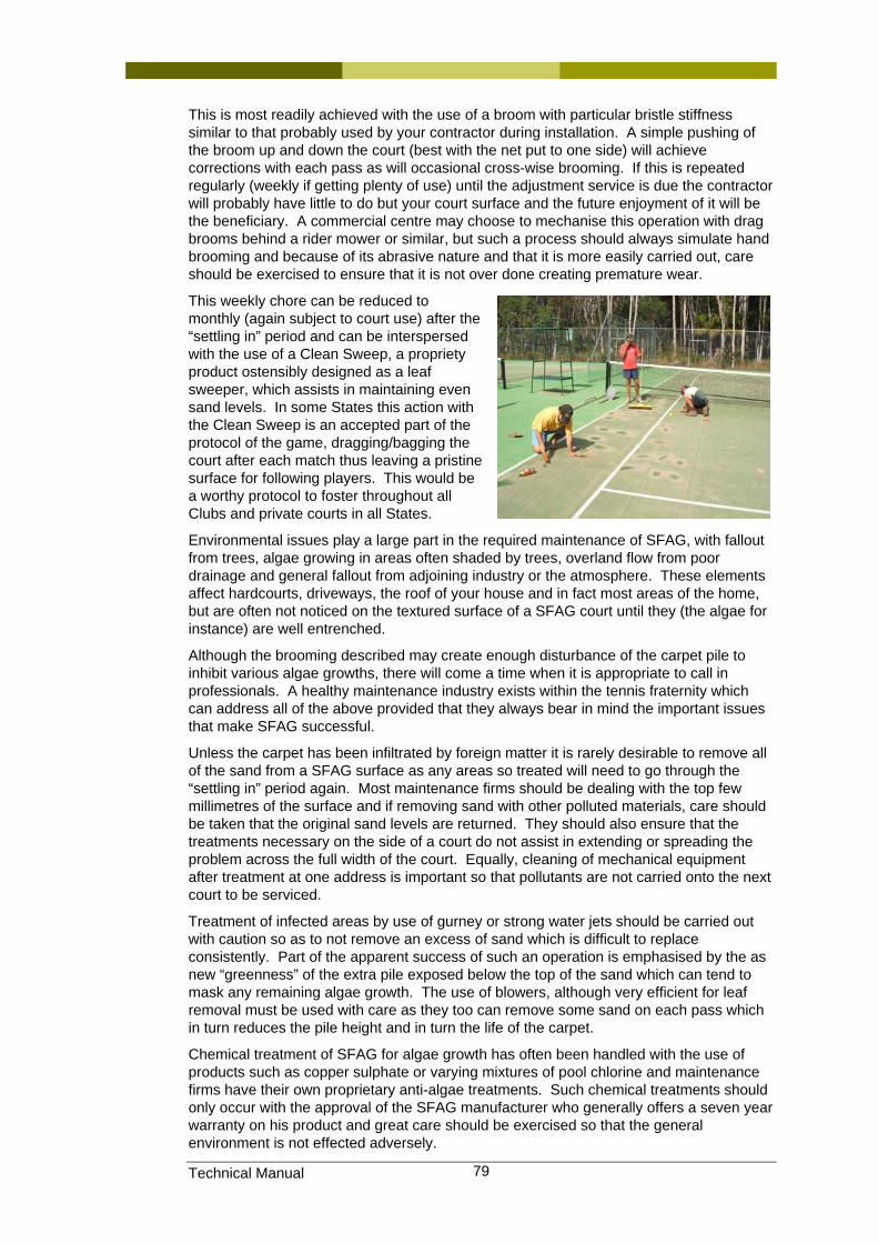
Technical Manual 79
This is most readily achieved with the use of a broom with particular bristle stiffness similar to that probably used by your contractor during installation. A simple pushing of the broom up and down the court (best with the net put to one side) will achieve corrections with each pass as will occasional cross-wise brooming. If this is repeated regularly (weekly if getting plenty of use) until the adjustment service is due the contractor will probably have little to do but your court surface and the future enjoyment of it will be the beneficiary. A commercial centre may choose to mechanise this operation with drag brooms behind a rider mower or similar, but such a process should always simulate hand brooming and because of its abrasive nature and that it is more easily carried out, care should be exercised to ensure that it is not over done creating premature wear.
This weekly chore can be reduced to monthly (again subject to court use) after the “settling in” period and can be interspersed with the use of a Clean Sweep, a propriety product ostensibly designed as a leaf sweeper, which assists in maintaining even sand levels. In some States this action with the Clean Sweep is an accepted part of the protocol of the game, dragging/bagging the court after each match thus leaving a pristine surface for following players. This would be a worthy protocol to foster throughout all Clubs and private courts in all States.
Environmental issues play a large part in the required maintenance of SFAG, with fallout from trees, algae growing in areas often shaded by trees, overland flow from poor drainage and general fallout from adjoining industry or the atmosphere. These elements affect hardcourts, driveways, the roof of your house and in fact most areas of the home, but are often not noticed on the textured surface of a SFAG court until they (the algae for instance) are well entrenched.
Although the brooming described may create enough disturbance of the carpet pile to inhibit various algae growths, there will come a time when it is appropriate to call in professionals. A healthy maintenance industry exists within the tennis fraternity which can address all of the above provided that they always bear in mind the important issues that make SFAG successful.
Unless the carpet has been infiltrated by foreign matter it is rarely desirable to remove all of the sand from a SFAG surface as any areas so treated will need to go through the “settling in” period again. Most maintenance firms should be dealing with the top few millimetres of the surface and if removing sand with other polluted materials, care should be taken that the original sand levels are returned. They should also ensure that the treatments necessary on the side of a court do not assist in extending or spreading the problem across the full width of the court. Equally, cleaning of mechanical equipment after treatment at one address is important so that pollutants are not carried onto the next court to be serviced.
Treatment of infected areas by use of gurney or strong water jets should be carried out with caution so as to not remove an excess of sand which is difficult to replace consistently. Part of the apparent success of such an operation is emphasised by the as new “greenness” of the extra pile exposed below the top of the sand which can tend to mask any remaining algae growth. The use of blowers, although very efficient for leaf removal must be used with care as they too can remove some sand on each pass which in turn reduces the pile height and in turn the life of the carpet.
Chemical treatment of SFAG for algae growth has often been handled with the use of products such as copper sulphate or varying mixtures of pool chlorine and maintenance firms have their own proprietary anti-algae treatments. Such chemical treatments should only occur with the approval of the SFAG manufacturer who generally offers a seven year warranty on his product and great care should be exercised so that the general environment is not effected adversely.
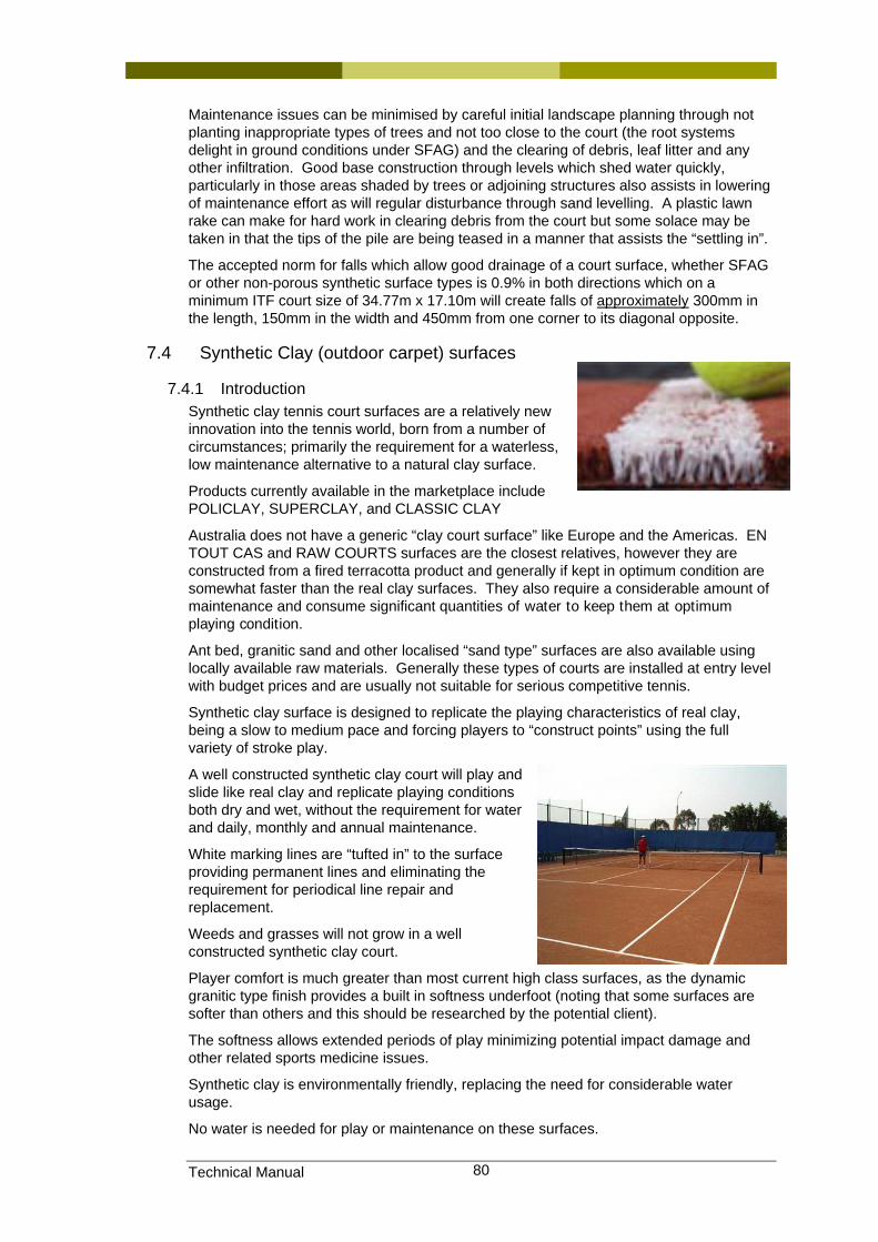
Technical Manual 80
Maintenance issues can be minimised by careful initial landscape planning through not planting inappropriate types of trees and not too close to the court (the root systems delight in ground conditions under SFAG) and the clearing of debris, leaf litter and any other infiltration. Good base construction through levels which shed water quickly, particularly in those areas shaded by trees or adjoining structures also assists in lowering of maintenance effort as will regular disturbance through sand levelling. A plastic lawn rake can make for hard work in clearing debris from the court but some solace may be taken in that the tips of the pile are being teased in a manner that assists the “settling in”.
The accepted norm for falls which allow good drainage of a court surface, whether SFAG or other non-porous synthetic surface types is 0.9% in both directions which on a minimum ITF court size of 34.77m x 17.10m will create falls of approximately 300mm in the length, 150mm in the width and 450mm from one corner to its diagonal opposite.
7.4 Synthetic Clay (outdoor carpet) surfaces
7.4.1 Introduction Synthetic clay tennis court surfaces are a relatively new innovation into the tennis world, born from a number of circumstances; primarily the requirement for a waterless, low maintenance alternative to a natural clay surface.
Products currently available in the marketplace include POLICLAY, SUPERCLAY, and CLASSIC CLAY
Australia does not have a generic “clay court surface” like Europe and the Americas. EN TOUT CAS and RAW COURTS surfaces are the closest relatives, however they are constructed from a fired terracotta product and generally if kept in optimum condition are somewhat faster than the real clay surfaces. They also require a considerable amount of maintenance and consume significant quantities of water to keep them at optimum playing condition.
Ant bed, granitic sand and other localised “sand type” surfaces are also available using locally available raw materials. Generally these types of courts are installed at entry level with budget prices and are usually not suitable for serious competitive tennis.
Synthetic clay surface is designed to replicate the playing characteristics of real clay, being a slow to medium pace and forcing players to “construct points” using the full variety of stroke play.
A well constructed synthetic clay court will play and slide like real clay and replicate playing conditions both dry and wet, without the requirement for water and daily, monthly and annual maintenance.
White marking lines are “tufted in” to the surface providing permanent lines and eliminating the requirement for periodical line repair and replacement.
Weeds and grasses will not grow in a well constructed synthetic clay court.
Player comfort is much greater than most current high class surfaces, as the dynamic granitic type finish provides a built in softness underfoot (noting that some surfaces are softer than others and this should be researched by the potential client).
The softness allows extended periods of play minimizing potential impact damage and other related sports medicine issues.
Synthetic clay is environmentally friendly, replacing the need for considerable water usage.
No water is needed for play or maintenance on these surfaces.
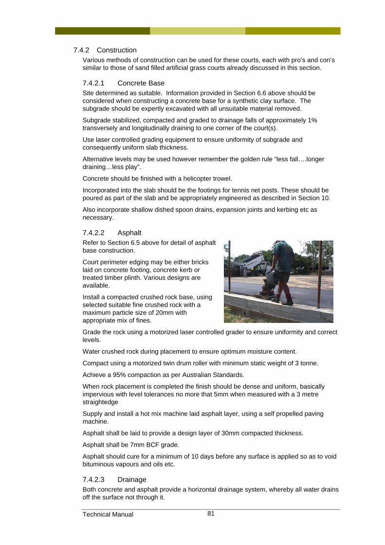
Technical Manual 81
7.4.2 Construction Various methods of construction can be used for these courts, each with pro’s and con’s similar to those of sand filled artificial grass courts already discussed in this section.
7.4.2.1 Concrete Base Site determined as suitable. Information provided in Section 6.6 above should be considered when constructing a concrete base for a synthetic clay surface. The subgrade should be expertly excavated with all unsuitable material removed.
Subgrade stabilized, compacted and graded to drainage falls of approximately 1% transversely and longitudinally draining to one corner of the court(s).
Use laser controlled grading equipment to ensure uniformity of subgrade and consequently uniform slab thickness.
Alternative levels may be used however remember the golden rule “less fall….longer draining…less play”.
Concrete should be finished with a helicopter trowel.
Incorporated into the slab should be the footings for tennis net posts. These should be poured as part of the slab and be appropriately engineered as described in Section 10.
Also incorporate shallow dished spoon drains, expansion joints and kerbing etc as necessary.
7.4.2.2 Asphalt Refer to Section 6.5 above for detail of asphalt base construction.
Court perimeter edging may be either bricks laid on concrete footing, concrete kerb or treated timber plinth. Various designs are available.
Install a compacted crushed rock base, using selected suitable fine crushed rock with a maximum particle size of 20mm with appropriate mix of fines.
Grade the rock using a motorized laser controlled grader to ensure uniformity and correct levels.
Water crushed rock during placement to ensure optimum moisture content.
Compact using a motorized twin drum roller with minimum static weight of 3 tonne.
Achieve a 95% compaction as per Australian Standards.
When rock placement is completed the finish should be dense and uniform, basically impervious with level tolerances no more that 5mm when measured with a 3 metre straightedge
Supply and install a hot mix machine laid asphalt layer, using a self propelled paving machine.
Asphalt shall be laid to provide a design layer of 30mm compacted thickness.
Asphalt shall be 7mm BCF grade.
Asphalt should cure for a minimum of 10 days before any surface is applied so as to void bituminous vapours and oils etc.
7.4.2.3 Drainage Both concrete and asphalt provide a horizontal drainage system, whereby all water drains off the surface not through it.
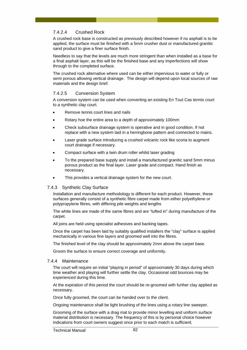
Technical Manual 82
7.4.2.4 Crushed Rock A crushed rock base is constructed as previously described however if no asphalt is to be applied, the surface must be finished with a 5mm crusher dust or manufactured granitic sand product to give a finer surface finish.
Needless to say that the levels are much more stringent than when installed as a base for a final asphalt layer, as this will be the finished base and any imperfections will show through to the completed surface.
The crushed rock alternative where used can be either impervious to water or fully or semi porous allowing vertical drainage. The design will depend upon local sources of raw materials and the design brief.
7.4.2.5 Conversion System A conversion system can be used when converting an existing En Tout Cas tennis court to a synthetic clay court.
• Remove tennis court lines and nails
• Rotary hoe the entire area to a depth of approximately 100mm
• Check subsurface drainage system is operative and in good condition. If not replace with a new system laid in a herringbone pattern and connected to mains.
• Laser grade surface introducing a crushed volcanic rock like scoria to augment court drainage if necessary.
• Compact surface with a twin drum roller whilst laser grading
• To the prepared base supply and install a manufactured granitic sand 5mm minus porous product as the final layer. Laser grade and compact. Hand finish as necessary.
• This provides a vertical drainage system for the new court.
7.4.3 Synthetic Clay Surface Installation and manufacture methodology is different for each product. However, these surfaces generally consist of a synthetic fibre carpet made from either polyethylene or polypropylene fibres, with differing pile weights and lengths
The white lines are made of the same fibres and are “tufted in” during manufacture of the carpet.
All joins are held using specialist adhesives and backing tapes.
Once the carpet has been laid by suitably qualified installers the “clay” surface is applied mechanically in various fine layers and groomed well into the fibres.
The finished level of the clay should be approximately 2mm above the carpet base.
Groom the surface to ensure correct coverage and uniformity.
7.4.4 Maintenance The court will require an initial “playing in period” of approximately 30 days during which time weather and playing will further settle the clay. Occasional odd bounces may be experienced during this time.
At the expiration of this period the court should be re-groomed with further clay applied as necessary.
Once fully groomed, the court can be handed over to the client.
Ongoing maintenance shall be light brushing of the lines using a rotary line sweeper.
Grooming of the surface with a drag mat to provide minor levelling and uniform surface material distribution is necessary. The frequency of this is by personal choice however indications from court owners suggest once prior to each match is sufficient.
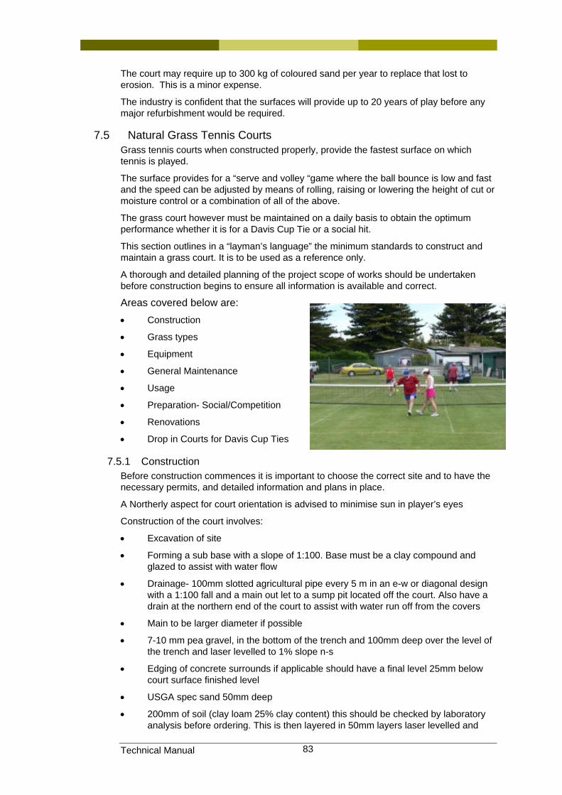
Technical Manual 83
The court may require up to 300 kg of coloured sand per year to replace that lost to erosion. This is a minor expense.
The industry is confident that the surfaces will provide up to 20 years of play before any major refurbishment would be required.
7.5 Natural Grass Tennis Courts Grass tennis courts when constructed properly, provide the fastest surface on which tennis is played.
The surface provides for a “serve and volley “game where the ball bounce is low and fast and the speed can be adjusted by means of rolling, raising or lowering the height of cut or moisture control or a combination of all of the above.
The grass court however must be maintained on a daily basis to obtain the optimum performance whether it is for a Davis Cup Tie or a social hit.
This section outlines in a “layman’s language” the minimum standards to construct and maintain a grass court. It is to be used as a reference only.
A thorough and detailed planning of the project scope of works should be undertaken before construction begins to ensure all information is available and correct.
Areas covered below are: • Construction
• Grass types
• Equipment
• General Maintenance
• Usage
• Preparation- Social/Competition
• Renovations
• Drop in Courts for Davis Cup Ties
7.5.1 Construction Before construction commences it is important to choose the correct site and to have the necessary permits, and detailed information and plans in place.
A Northerly aspect for court orientation is advised to minimise sun in player’s eyes
Construction of the court involves:
• Excavation of site
• Forming a sub base with a slope of 1:100. Base must be a clay compound and glazed to assist with water flow
• Drainage- 100mm slotted agricultural pipe every 5 m in an e-w or diagonal design with a 1:100 fall and a main out let to a sump pit located off the court. Also have a drain at the northern end of the court to assist with water run off from the covers
• Main to be larger diameter if possible
• 7-10 mm pea gravel, in the bottom of the trench and 100mm deep over the level of the trench and laser levelled to 1% slope n-s
• Edging of concrete surrounds if applicable should have a final level 25mm below court surface finished level
• USGA spec sand 50mm deep
• 200mm of soil (clay loam 25% clay content) this should be checked by laboratory analysis before ordering. This is then layered in 50mm layers laser levelled and
Technical Manual 84
rolled with a 1ton roller until 200 mm final layer is laser levelled and rolled to consolidate
• Laser levelling to be with a fall n-s with a +- 1.5mm variation an final grade of 1:100 is recommended
• Washed turf suitable for court usage laid and watered/fertilized regular until turf established
• Surveying of the site for lines/post layout/nets fences/lighting (use a good reputable survey company)
• Installation of net post sleeves/centre tie down
• Installation of fences/lighting
• Installation of irrigation/watering points
Sleeves for net post should be concreted in at a slight angle (.5 of a degree) outwards to allow for tension forces of the net and also be set below level of finished playing level so not to damage machinery.
Post sleeves should be embedded in concrete 1 m deep by 300mm wide.
Sleeves should also be capped when not in use
7.5.2 Grass types There is a variety of turf available today that would be suitable for tennis courts.
Some of these are:
• QLD blue couch
• Conquest
• Greenlees park in warmer climates
• Legend (although obtaining a pure strand of this variety is an issue at the time of writing)
• 328 variety
There are always new varieties being bred, so these choices will change over time once the newer varieties have proven themselves.
7.5.3 Equipment To obtain the best surface for the grass court the following equipment should be purchased:
Depending on the number of courts the following is the minimum for one court
• Cylinder type mower with 11 blades i.e. Toro 1600. John Deere 220, preferably with grooming reels for de-thatching
• Battery powered Line marker i.e. Supa turf
• Roller 1.5 tonnes max
• Squeezes/Supa -sopper
• Small fertiliser spreader
• Small sprayer
• Covers and sand bags
• Edger
• Level lawn
• Wheel barrow and shovels
Technical Manual 85
• 19mm hose with fish mouth nozzle and soaker connection
• Scarifier
• Polishing dew roller with weights
7.5.4 General Maintenance Maintenance of the court is all year, with the start of the season and finishing with a renovation in spring / summer in preparation for continued use through the year.
Maintenance involves different routines depending on levels of play. For major tournament play such as Davis Cup or state and major championship play, this will involve intensive turf management.
For social play the level will not be as severe.
Maintenance required for both social and major tournaments involves the following:
• Mowing
• Rolling
• Fertilising
• Spraying chemicals for pests and diseases
• Repairing base lines, nets, line marking
• Light “dust ins” and general court maintenance
7.5.5 Usage Depending on the type of use the court should be rotated or rested on a regular basis.
If the use is for social ply only the court should be rotated more and HOC should be raised to accommodate the level of play. It is important that committees understand that the turf will not hold up with constant usage and damage to the surface or excessive wear could result in a poor performing court when the time arises for it to be used for championship play.
It is also important that sufficient time be allocated for court(s) to recover from renovations.
For major tournaments, allocation of certain courts and a time regulation should be utilised.
The main court should NOT be used for practice until the finals with the exception of restricted time generally no more than 1 hour for teams to familiarise themselves with the characteristics of the court.
The practice courts and the main court should be maintained the same with no deviation in preparation.
7.5.6 Preparation - social/competition The Height of Cut (HOC) for social play can be as high as 8mm to allow for the surface to withstand high usage. If possible allow a day between cuttings and lightly roll to maintain good even bounce.
Vary the direction of the cut to prevent “grain” from becoming set.
For championship play the HOC is usually around 4-5mm or lower depending on the event, and the speed of the court. Mow in a N-S direction
The application of a nitrogen / iron fertiliser will provide more skid of the ball and a quicker surface a week out from the event.
Rolling and watering the courts can be used to find the balance leading up to the event to find the right amount of bounce for players.
Technical Manual 86
Davis Cup Preparation is unique as the home team can dictate the type of surface it requires and this is reflected in the court preparation.
7.5.7 Renovations At the end of the playing season or around spring/summer the court(s) should be renovated.
This involves
• Taking a soil sample and testing for nutrient deficiencies
• Scarifying the surface to remove thatch build up.
• Coring the surface to allow air entry and allow granular fertiliser to enter the profile
• Topdressing using the same medium as constructed. This is very important.
• Laser Levelling if required
• Rubbing in the top dressing material with level lawns
• Fertilising based on a soil test result
• Applying chemicals to control pests/diseases
• Bring into play over 4-8 weeks depending on situation and usage requirements this involves lowering the HOC and light rolling, watering and finally reline marking
There is no substitute for a good renovation and taking short cuts is not advisable for long term playability of the court
7.5.8 Drop in courts In recent years the Strathayr Company in conjunction with Tennis Australia has developed a portable drop in court.
This involves the use of mesh elements and a drainage system combined to allow portability around the country for mainly Davis Cup ties if they are to be played on a natural turf court over artificial court.
• The squares are 2.4m x 2.4m (6m2) 200mm deep and weigh 1.7 tonnes.
• The soil is 150mm deep and is reinforced with mesh reflex elements squares fit together by forking into place.
• A court consists of 160modules and each module is numbered for a perfect fit.
This system allows the surface to be placed into position within 12 weeks.
7.5.9 Irrigation Installation of an irrigation system will provide correct amounts of water to the court
The Toro 2001 series sprinklers are ideal for single courts.
To install a Toro 2001 series on a single court will require 2 X half circle sprinklers and 4 X quarter circle sprinklers
For double courts the system can be configured to run independently for a two-court application. This will involve upgrading or installing a controller with sufficient stations to cover two courts.
A main controller with at least 4 stations will also be required.
As with all irrigation systems connected to the mains water supply, there needs to be a back flow prevention device. Generally a dual check valve is sufficient, but check with the local Council for their requirements.
Companies with trained staff with irrigation installers licences are available in Qld to install such systems. One company is TIS (Turf Irrigation Systems) at Capalaba in Brisbane’s eastern suburbs.

Technical Manual 87
Generally to install a system on a single court will cost around $4,500.00 (as at the time of writing).
If a club wishes to do the installation itself, be sure that the person installing the system has the restricted plumber’s (irrigation installer’s licence).
7.5.10 Grass court maintenance Grass courts require maintenance throughout the year.
This will ensure
• A firm surface that provides good traction for players
• An even bounce of good height
• Even density and colour
• Good presentation of the court being weed, disease and pest free.
After renovation the following maintenance is generally undertaken, and can be broken down into seasonal requirements.
N.B: Please note that the seasonal months submitted here are related to central Brisbane and are related to on site weather station readings collected over a period of time. It is important to remember that these can and could change. It is advisable to check local conditions and make necessary changes to individual clubs programs
SUMMER Season in QLD: December – Early March
Mowing: In general remove only a third of the leaf and mow only when surface is dry.
The court should be mowed at least every second day, which will provide a tight surface. In some places mowing daily will need to be carried out.
Hoc will be around the 4 to 8mm area depending on use and competition.
It might be required that the court be double cut on occasions, depending on growth.
Be sure that the blades are regularly sharpened by back lapping the cylinder with grinding paste.
Irrigation should be applied deep and infrequent and ideally should be applied based on ET rates for the area. Root depth also needs to be taken into account when doing this.
7.5.10.1 Spraying A person with an appropriate chemical licence, such as “Chemcert” or “ACDC” should undertake the application of any hazardous chemicals. The individual club should also have a chemical distribution licence. The chemicals should also be applied as per manufacturer’s recommendations.
Applications of fungicide for diseases relating to summer months will need to be applied. These diseases can be either root or leaf and appropriate fungicides will control or eradicate any outbreaks.
Spraying for pests such as armyworm, couch mites, couch fly, and black beetle can be controlled with appropriate pesticide chemicals.
Applications of herbicides can be undertaken throughout the season, but best applied before renovation to allow the turf to recover.
7.5.10.2 Wetting Agents Wetting agents are applied when the profile needs an even wetting up or where there is lack of sufficient rainfall to evenly wet the profile.
Technical Manual 88
7.5.10.3 Fertilising: Before starting a fertiliser program it is important to obtain a soil and if possible leaf analysis of the court to determine the exact nutrient requirements and deficiencies and correct these before going into a maintenance program.
Soil tests should be conducted at least twice per year to gauge soil and plant requirements.
In general after renovations, a fertiliser higher in phosphorus should be utilised to establish the root system and also enable the addition of organic fertiliser into the profile.
Regular fertilising with a mixture of Nitrogen and Potassium ratio of 2:1 will ensure good recovery from wear and produce lateral growth, as well as maintain the colour and speed of the surface.
It is also important to add trace elements as required, but soil tests will indicate any deficiencies.
Turf specialist companies such as but not limited to- Globe, Nuturf, Simplot, T&I and Floratine have a range of fertilisers to suit requirements for closely cut turf.
The fertiliser can be applied in granular or in liquid form.
In all cases of fertiliser application, the directions of application on the label should be adhered to.
The ratio will then drop from 2:1 to 1:1 from late February to prepare for colder months.
With the profile being mainly clay it is important to consider the application of liquids and foliar fertilisers to assist with maintaining a dryer profile leading up to games.
All companies have a folia range and these should be examined to ensure that the correct product is applied.
Winter Season in QLD –March to September
Fertilise with a ratio of N: K 1: 1. And in colder areas a ratio of 1:2 could be considered.
This will enable continued recovery of the baseline and provide sufficient nitrogen to maintain growth.
Be careful to watch the nitrogen component of the product to ensure that it is not too high.
Adding sulphate of iron (chelate type) and magnesium sulphate will assist with colour.
7.5.10.4 Mowing: Mowing to be carried out to remove one-third the leaf tip generally, but again local conditions can change this to everyday if temperatures increase top growth. Mowing twice per week should be considered where temperatures are in the colder regions.
Raising the HOC a millimetre or two will provide better protection to the surface from excessive wear
Irrigation again depends on ET rates but generally less than for summer months
7.5.10.5 Dethatching and aeration During the summer months a regular dethatching program should be undertaken to limit the amount of thatch build up and lateral growth, which left unchecked, will result in a slow court and “spongy” surface.
The operator will need to judge when the use of this machine is needed.
The use of a pedestrian scarifier or use of the dethatching vertical blades on the reel mower will remove sufficient thatch. It is important not to allow the blades to bring up soil as this will result tin the surface taking too long to recover and will leave unsightly lines. Generally set blades 1mm below HOC.
Technical Manual 89
Aeration usually involves the use of a “vertidrain” with 8mm tynes. Again the manger will need to access the frequency and tyne selection relevant to court usage and what he/she wishes to achieve by using this practice.
7.5.10.6 Topdressing / "dust ins" Application at renovation of the same medium as the profile to top dress the court will be required. The medium should be dry if possible to allow ease of application. Once applied the surface is rubbed in with level lawns to ensure good surface contact.
Periodically the court can be “dusted" using a sieved material to lightly cover the court to assist with wear recovery particularly on the base line and centre areas.
7.5.10.7 Rolling Rolling of the court should be undertaken to firm the surface not to make the surface “rock hard”.
In the summer months when the surface has a lot of “grass” the rolling can be done frequently. It is important to finish by cross rolling to eliminate lines from the roller.
Rolling with the playing court first then finishing by rolling across court will ensure that there is no deviations in he surface that will affect the balls bounce.
Double rolling, that is coming back on a slight angle along the first line of the roll, will also help with this.
Always take into consideration the condition of the soil. If the profile is too wet, rolling may cause ridging and if too dry it will be a waste of time.
Roll outside the playing area first if ridging is a concern and inspect before proceeding.
The amount of rolling will determine how high the ball bounces and generally for social competition a bounce from knee to waist height is ok.
Roller weights should be 1 tonne and 2 tonne rollers
7.5.10.8 Spring (Renovation Season) - October to December Renovation should be carried out at the end of the season and will involve the following practices:
• Scarifying of surface and clean up
• Aeration (coring)
• Fertilising with amendments
• Topdressing
• Watering
• Bringing into play by light rolling and reducing HOC to a playing HOC
Refer to previous section
7.6 Compacted earth bases
7.6.1 European Clay
7.6.2 Introduction There has been a lot of discussion in recent times about the need for juniors to be trained on European type clay courts. Most top coaches agree that training on clay courts provides benefit for aspiring young players. The need to ‘work’ for a point builds strength and endurance, whilst cultivating a strong technique.
The downside for clubs and users is that a clay court requires more maintenance than hard courts and synthetic grass courts. Do the advantages of clay courts outweigh the maintenance problems?
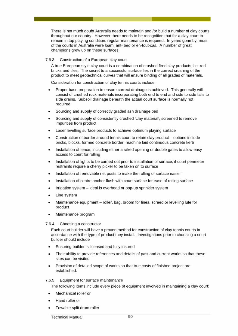
Technical Manual 90
There is not much doubt Australia needs to maintain and /or build a number of clay courts throughout our country. However there needs to be recognition that for a clay court to remain in top playing condition, regular maintenance is required. In years gone by, most of the courts in Australia were loam, ant- bed or en-tout-cas. A number of great champions grew up on these surfaces.
7.6.3 Construction of a European clay court A true European style clay court is a combination of crushed fired clay products, i.e. red bricks and tiles. The secret to a successful surface lies in the correct crushing of the product to meet geotechnical curves that will ensure binding of all grades of materials.
Consideration for construction of clay tennis courts include:
• Proper base preparation to ensure correct drainage is achieved. This generally will consist of crushed rock materials incorporating both end to end and side to side falls to side drains. Subsoil drainage beneath the actual court surface is normally not required.
• Sourcing and supply of correctly graded ash drainage bed
• Sourcing and supply of consistently crushed ‘clay material’, screened to remove impurities from product
• Laser levelling surface products to achieve optimum playing surface
• Construction of border around tennis court to retain clay product – options include bricks, blocks, formed concrete border, machine laid continuous concrete kerb
• Installation of fence, including either a raked opening or double gates to allow easy access to court for rolling
• Installation of lights to be carried out prior to installation of surface, if court perimeter restraints require a cherry picker to be taken on to surface
• Installation of removable net posts to make the rolling of surface easier
• Installation of centre anchor flush with court surface for ease of rolling surface
• Irrigation system – ideal is overhead or pop-up sprinkler system
• Line system
• Maintenance equipment – roller, bag, broom for lines, screed or levelling lute for product
• Maintenance program
7.6.4 Choosing a constructor Each court builder will have a proven method for construction of clay tennis courts in accordance with the type of product they install. Investigations prior to choosing a court builder should include
• Ensuring builder is licensed and fully insured
• Their ability to provide references and details of past and current works so that these sites can be visited
• Provision of detailed scope of works so that true costs of finished project are established.
7.6.5 Equipment for surface maintenance The following items include every piece of equipment involved in maintaining a clay court:
• Mechanical roller or
• Hand roller or
• Towable split drum roller

Technical Manual 91
• Timber court screed
• Clay grooming rake
• Clay packing hammer
• Smooth bristled broom or line sweeper for lines
• Light net bag
• Timber rubber squeegee
• Watering system
• Aussie clean sweep
• Calcium chloride and spreader
• Light aluminium grain shovel
• Wheelbarrow
• Irrigation system
A single residential clay court would only require an irrigation system, a broom for sweeping lines, a roller [towable or hand roller], light net bag, and a timber court screed.
A multi-court commercial clay court centre would be best to have:
• an irrigation system
• a mechanical or towable split-drum roller
• light net bags for each court
• line sweeper for each court
• a timber court screed.
It would be up to the individual club to decide the extent of ongoing maintenance they undertake, then other equipment like shovels, calcium chloride, and the like can be considered for purchase, or the court builder can provide an ongoing maintenance service using his own equipment as required.
[Calcium chloride will reduce the amount of watering required in hot weather].
7.6.6 General Maintenance Maintenance of the court is ongoing, and maintenance levels required are dependant on court usage and weather conditions. Maintaining your clay surface requires a regular program to ensure optimum performance, and to extend the life of the court. The procedure involves bagging, watering, sweeping and rolling the surface in accordance with court usage.
CLAY COURT MAINTENANCE SUMMARY
Procedure Schedule
Timber screed Inspect court, repair divots and clear court of any debris
Bagging Use only the light net bag.
Frequency: daily and after play, parallel to net and lengthwise. Alternate the direction of bagging.
Sweep lines
1. Before watering so dust does not settle or stick to lines when watering.
2. Before rolling, so roller does not damage lines, and avoid turning roller directly on lines
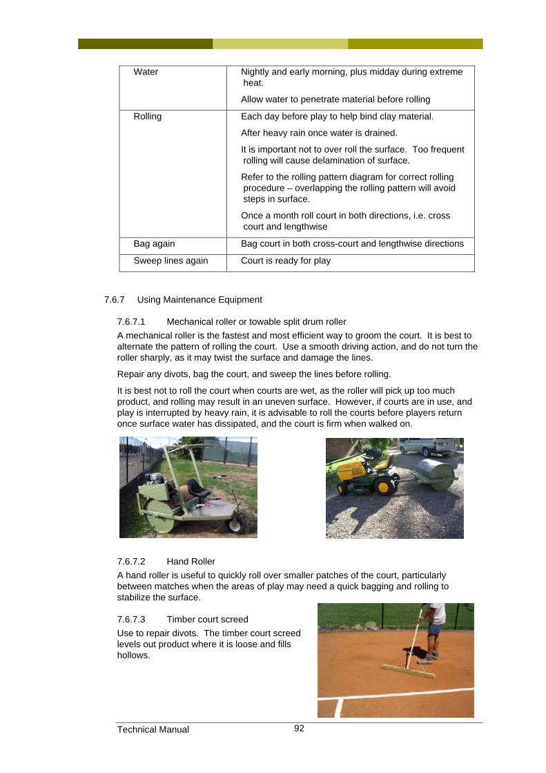
Technical Manual 92
Water Nightly and early morning, plus midday during extreme heat.
Allow water to penetrate material before rolling
Rolling Each day before play to help bind clay material.
After heavy rain once water is drained.
It is important not to over roll the surface. Too frequent rolling will cause delamination of surface.
Refer to the rolling pattern diagram for correct rolling procedure – overlapping the rolling pattern will avoid steps in surface.
Once a month roll court in both directions, i.e. cross court and lengthwise
Bag again Bag court in both cross-court and lengthwise directions
Sweep lines again Court is ready for play
7.6.7 Using Maintenance Equipment
7.6.7.1 Mechanical roller or towable split drum roller A mechanical roller is the fastest and most efficient way to groom the court. It is best to alternate the pattern of rolling the court. Use a smooth driving action, and do not turn the roller sharply, as it may twist the surface and damage the lines.
Repair any divots, bag the court, and sweep the lines before rolling.
It is best not to roll the court when courts are wet, as the roller will pick up too much product, and rolling may result in an uneven surface. However, if courts are in use, and play is interrupted by heavy rain, it is advisable to roll the courts before players return once surface water has dissipated, and the court is firm when walked on.
7.6.7.2 Hand Roller A hand roller is useful to quickly roll over smaller patches of the court, particularly between matches when the areas of play may need a quick bagging and rolling to stabilize the surface.
7.6.7.3 Timber court screed Use to repair divots. The timber court screed levels out product where it is loose and fills hollows.
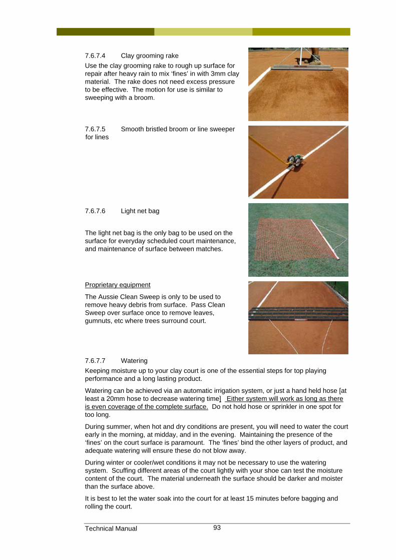
Technical Manual 93
7.6.7.4 Clay grooming rake Use the clay grooming rake to rough up surface for repair after heavy rain to mix ‘fines’ in with 3mm clay material. The rake does not need excess pressure to be effective. The motion for use is similar to sweeping with a broom.
7.6.7.5 Smooth bristled broom or line sweeper for lines
7.6.7.6 Light net bag
The light net bag is the only bag to be used on the surface for everyday scheduled court maintenance, and maintenance of surface between matches.
Proprietary equipment
The Aussie Clean Sweep is only to be used to remove heavy debris from surface. Pass Clean Sweep over surface once to remove leaves, gumnuts, etc where trees surround court.
7.6.7.7 Watering Keeping moisture up to your clay court is one of the essential steps for top playing performance and a long lasting product.
Watering can be achieved via an automatic irrigation system, or just a hand held hose [at least a 20mm hose to decrease watering time] Either system will work as long as there is even coverage of the complete surface. Do not hold hose or sprinkler in one spot for too long.
During summer, when hot and dry conditions are present, you will need to water the court early in the morning, at midday, and in the evening. Maintaining the presence of the ‘fines’ on the court surface is paramount. The ‘fines’ bind the other layers of product, and adequate watering will ensure these do not blow away.
During winter or cooler/wet conditions it may not be necessary to use the watering system. Scuffing different areas of the court lightly with your shoe can test the moisture content of the court. The material underneath the surface should be darker and moister than the surface above.
It is best to let the water soak into the court for at least 15 minutes before bagging and rolling the court.
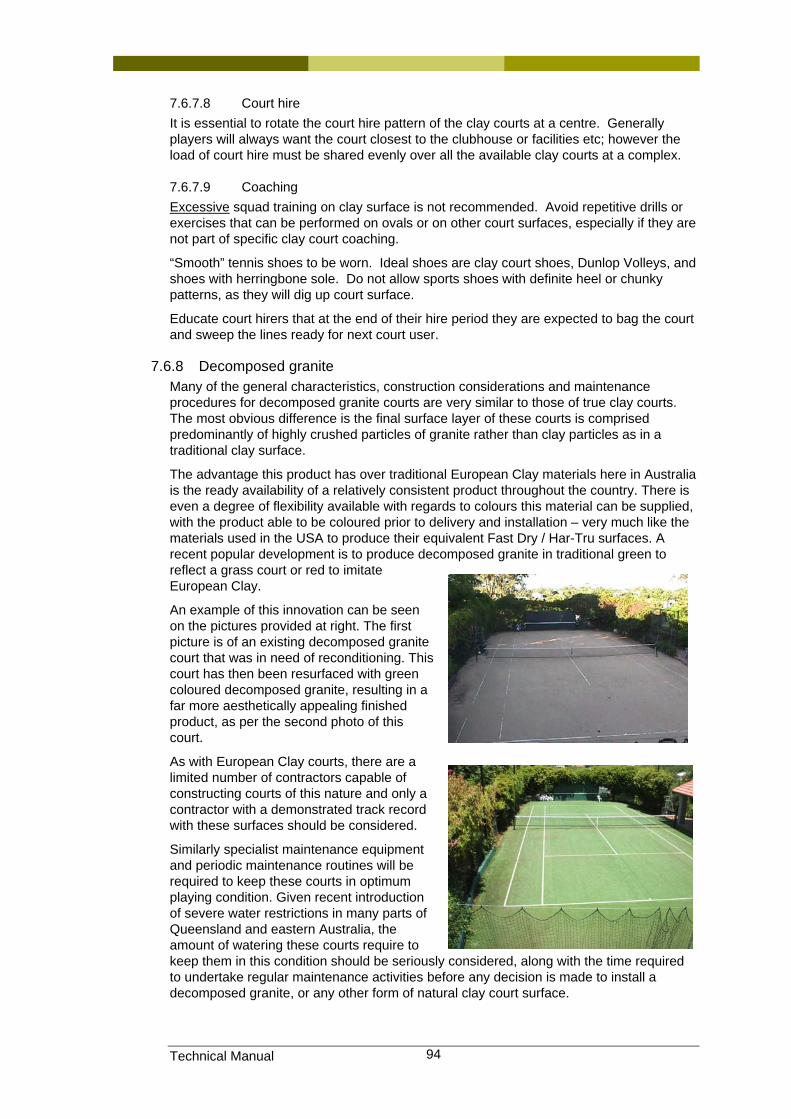
Technical Manual 94
7.6.7.8 Court hire It is essential to rotate the court hire pattern of the clay courts at a centre. Generally players will always want the court closest to the clubhouse or facilities etc; however the load of court hire must be shared evenly over all the available clay courts at a complex.
7.6.7.9 Coaching Excessive squad training on clay surface is not recommended. Avoid repetitive drills or exercises that can be performed on ovals or on other court surfaces, especially if they are not part of specific clay court coaching.
“Smooth” tennis shoes to be worn. Ideal shoes are clay court shoes, Dunlop Volleys, and shoes with herringbone sole. Do not allow sports shoes with definite heel or chunky patterns, as they will dig up court surface.
Educate court hirers that at the end of their hire period they are expected to bag the court and sweep the lines ready for next court user.
7.6.8 Decomposed granite Many of the general characteristics, construction considerations and maintenance procedures for decomposed granite courts are very similar to those of true clay courts. The most obvious difference is the final surface layer of these courts is comprised predominantly of highly crushed particles of granite rather than clay particles as in a traditional clay surface.
The advantage this product has over traditional European Clay materials here in Australia is the ready availability of a relatively consistent product throughout the country. There is even a degree of flexibility available with regards to colours this material can be supplied, with the product able to be coloured prior to delivery and installation – very much like the materials used in the USA to produce their equivalent Fast Dry / Har-Tru surfaces. A recent popular development is to produce decomposed granite in traditional green to reflect a grass court or red to imitate European Clay.
An example of this innovation can be seen on the pictures provided at right. The first picture is of an existing decomposed granite court that was in need of reconditioning. This court has then been resurfaced with green coloured decomposed granite, resulting in a far more aesthetically appealing finished product, as per the second photo of this court.
As with European Clay courts, there are a limited number of contractors capable of constructing courts of this nature and only a contractor with a demonstrated track record with these surfaces should be considered.
Similarly specialist maintenance equipment and periodic maintenance routines will be required to keep these courts in optimum playing condition. Given recent introduction of severe water restrictions in many parts of Queensland and eastern Australia, the amount of watering these courts require to keep them in this condition should be seriously considered, along with the time required to undertake regular maintenance activities before any decision is made to install a decomposed granite, or any other form of natural clay court surface.

Technical Manual 95
7.7 Information sources, Standards and Codes.
Equipment photos – courtesy of RAW Courts
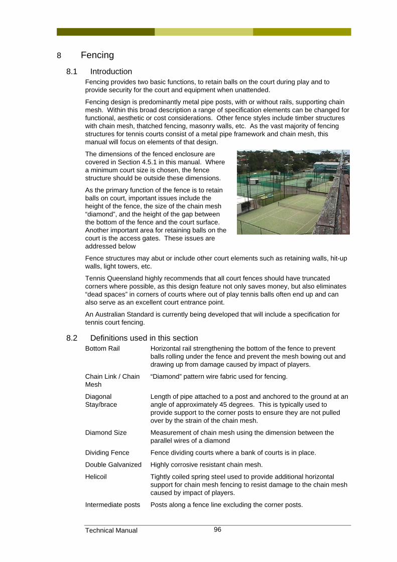
Technical Manual 96
8 Fencing
8.1 Introduction Fencing provides two basic functions, to retain balls on the court during play and to provide security for the court and equipment when unattended.
Fencing design is predominantly metal pipe posts, with or without rails, supporting chain mesh. Within this broad description a range of specification elements can be changed for functional, aesthetic or cost considerations. Other fence styles include timber structures with chain mesh, thatched fencing, masonry walls, etc. As the vast majority of fencing structures for tennis courts consist of a metal pipe framework and chain mesh, this manual will focus on elements of that design.
The dimensions of the fenced enclosure are covered in Section 4.5.1 in this manual. Where a minimum court size is chosen, the fence structure should be outside these dimensions.
As the primary function of the fence is to retain balls on court, important issues include the height of the fence, the size of the chain mesh “diamond”, and the height of the gap between the bottom of the fence and the court surface. Another important area for retaining balls on the court is the access gates. These issues are addressed below
Fence structures may abut or include other court elements such as retaining walls, hit-up walls, light towers, etc.
Tennis Queensland highly recommends that all court fences should have truncated corners where possible, as this design feature not only saves money, but also eliminates “dead spaces” in corners of courts where out of play tennis balls often end up and can also serve as an excellent court entrance point.
An Australian Standard is currently being developed that will include a specification for tennis court fencing.
8.2 Definitions used in this section Bottom Rail Horizontal rail strengthening the bottom of the fence to prevent
balls rolling under the fence and prevent the mesh bowing out and drawing up from damage caused by impact of players.
Chain Link / Chain Mesh
“Diamond” pattern wire fabric used for fencing.
Diagonal Stay/brace
Length of pipe attached to a post and anchored to the ground at an angle of approximately 45 degrees. This is typically used to provide support to the corner posts to ensure they are not pulled over by the strain of the chain mesh.
Diamond Size Measurement of chain mesh using the dimension between the parallel wires of a diamond
Dividing Fence Fence dividing courts where a bank of courts is in place.
Double Galvanized Highly corrosive resistant chain mesh.
Helicoil Tightly coiled spring steel used to provide additional horizontal support for chain mesh fencing to resist damage to the chain mesh caused by impact of players.
Intermediate posts Posts along a fence line excluding the corner posts.
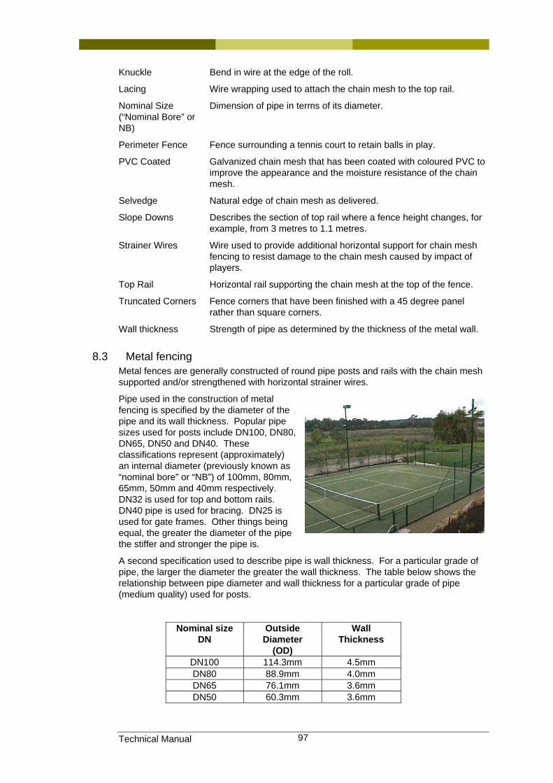
Technical Manual 97
Knuckle Bend in wire at the edge of the roll.
Lacing Wire wrapping used to attach the chain mesh to the top rail.
Nominal Size (“Nominal Bore” or NB)
Dimension of pipe in terms of its diameter.
Perimeter Fence Fence surrounding a tennis court to retain balls in play.
PVC Coated Galvanized chain mesh that has been coated with coloured PVC to improve the appearance and the moisture resistance of the chain mesh.
Selvedge Natural edge of chain mesh as delivered.
Slope Downs Describes the section of top rail where a fence height changes, for example, from 3 metres to 1.1 metres.
Strainer Wires Wire used to provide additional horizontal support for chain mesh fencing to resist damage to the chain mesh caused by impact of players.
Top Rail Horizontal rail supporting the chain mesh at the top of the fence.
Truncated Corners Fence corners that have been finished with a 45 degree panel rather than square corners.
Wall thickness Strength of pipe as determined by the thickness of the metal wall.
8.3 Metal fencing Metal fences are generally constructed of round pipe posts and rails with the chain mesh supported and/or strengthened with horizontal strainer wires.
Pipe used in the construction of metal fencing is specified by the diameter of the pipe and its wall thickness. Popular pipe sizes used for posts include DN100, DN80, DN65, DN50 and DN40. These classifications represent (approximately) an internal diameter (previously known as “nominal bore” or “NB”) of 100mm, 80mm, 65mm, 50mm and 40mm respectively. DN32 is used for top and bottom rails. DN40 pipe is used for bracing. DN25 is used for gate frames. Other things being equal, the greater the diameter of the pipe the stiffer and stronger the pipe is.
A second specification used to describe pipe is wall thickness. For a particular grade of pipe, the larger the diameter the greater the wall thickness. The table below shows the relationship between pipe diameter and wall thickness for a particular grade of pipe (medium quality) used for posts.
Nominal size DN
Outside Diameter
(OD)
Wall Thickness
DN100 114.3mm 4.5mm DN80 88.9mm 4.0mm DN65 76.1mm 3.6mm DN50 60.3mm 3.6mm
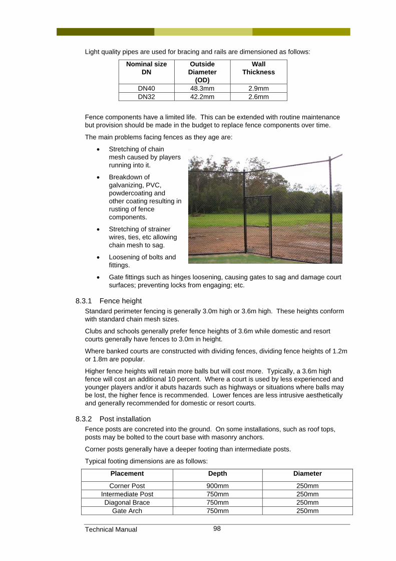
Technical Manual 98
Light quality pipes are used for bracing and rails are dimensioned as follows:
Nominal size DN
Outside Diameter
(OD)
Wall Thickness
DN40 48.3mm 2.9mm DN32 42.2mm 2.6mm
Fence components have a limited life. This can be extended with routine maintenance but provision should be made in the budget to replace fence components over time.
The main problems facing fences as they age are:
• Stretching of chain mesh caused by players running into it.
• Breakdown of galvanizing, PVC, powdercoating and other coating resulting in rusting of fence components.
• Stretching of strainer wires, ties, etc allowing chain mesh to sag.
• Loosening of bolts and fittings.
• Gate fittings such as hinges loosening, causing gates to sag and damage court surfaces; preventing locks from engaging; etc.
8.3.1 Fence height Standard perimeter fencing is generally 3.0m high or 3.6m high. These heights conform with standard chain mesh sizes.
Clubs and schools generally prefer fence heights of 3.6m while domestic and resort courts generally have fences to 3.0m in height.
Where banked courts are constructed with dividing fences, dividing fence heights of 1.2m or 1.8m are popular.
Higher fence heights will retain more balls but will cost more. Typically, a 3.6m high fence will cost an additional 10 percent. Where a court is used by less experienced and younger players and/or it abuts hazards such as highways or situations where balls may be lost, the higher fence is recommended. Lower fences are less intrusive aesthetically and generally recommended for domestic or resort courts.
8.3.2 Post installation Fence posts are concreted into the ground. On some installations, such as roof tops, posts may be bolted to the court base with masonry anchors.
Corner posts generally have a deeper footing than intermediate posts.
Typical footing dimensions are as follows:
Placement Depth Diameter
Corner Post 900mm 250mm Intermediate Post 750mm 250mm Diagonal Brace 750mm 250mm
Gate Arch 750mm 250mm
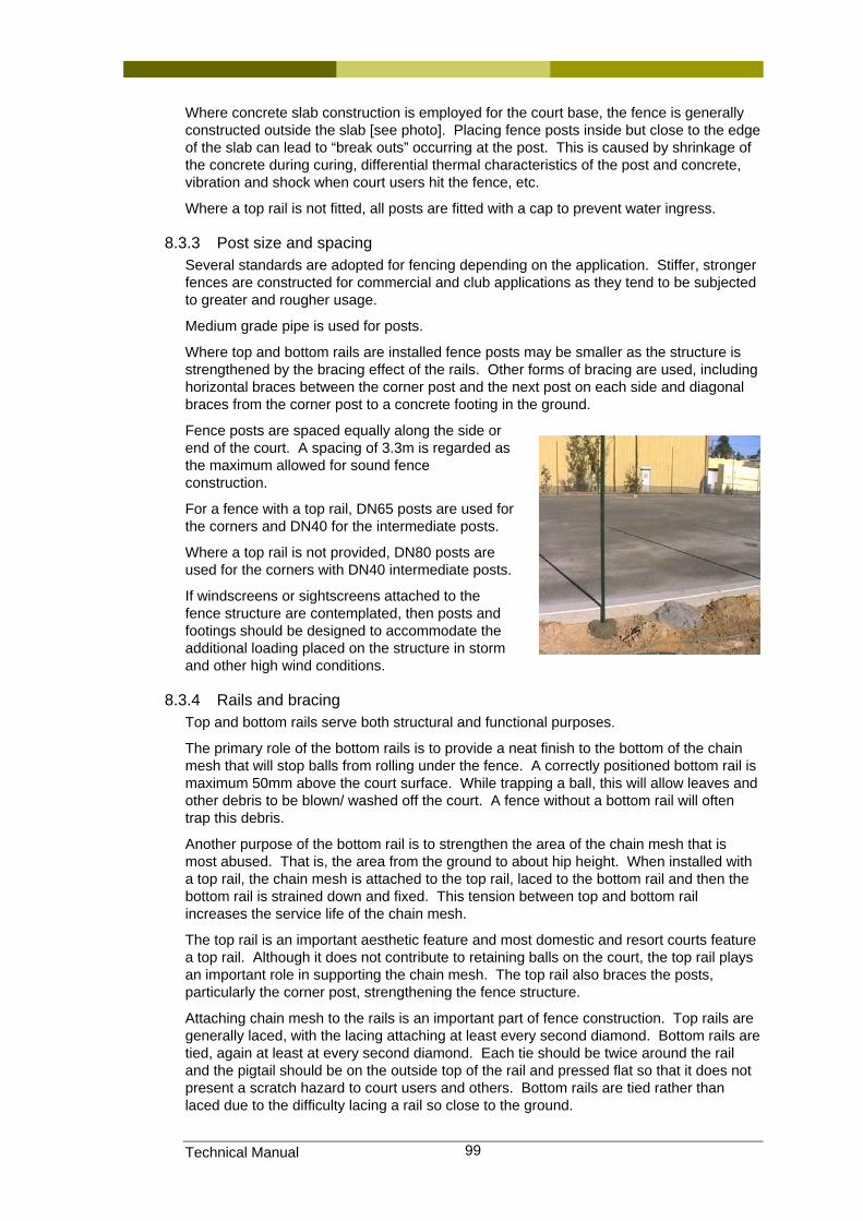
Technical Manual 99
Where concrete slab construction is employed for the court base, the fence is generally constructed outside the slab [see photo]. Placing fence posts inside but close to the edge of the slab can lead to “break outs” occurring at the post. This is caused by shrinkage of the concrete during curing, differential thermal characteristics of the post and concrete, vibration and shock when court users hit the fence, etc.
Where a top rail is not fitted, all posts are fitted with a cap to prevent water ingress.
8.3.3 Post size and spacing Several standards are adopted for fencing depending on the application. Stiffer, stronger fences are constructed for commercial and club applications as they tend to be subjected to greater and rougher usage.
Medium grade pipe is used for posts.
Where top and bottom rails are installed fence posts may be smaller as the structure is strengthened by the bracing effect of the rails. Other forms of bracing are used, including horizontal braces between the corner post and the next post on each side and diagonal braces from the corner post to a concrete footing in the ground.
Fence posts are spaced equally along the side or end of the court. A spacing of 3.3m is regarded as the maximum allowed for sound fence construction.
For a fence with a top rail, DN65 posts are used for the corners and DN40 for the intermediate posts.
Where a top rail is not provided, DN80 posts are used for the corners with DN40 intermediate posts.
If windscreens or sightscreens attached to the fence structure are contemplated, then posts and footings should be designed to accommodate the additional loading placed on the structure in storm and other high wind conditions.
8.3.4 Rails and bracing Top and bottom rails serve both structural and functional purposes.
The primary role of the bottom rails is to provide a neat finish to the bottom of the chain mesh that will stop balls from rolling under the fence. A correctly positioned bottom rail is maximum 50mm above the court surface. While trapping a ball, this will allow leaves and other debris to be blown/ washed off the court. A fence without a bottom rail will often trap this debris.
Another purpose of the bottom rail is to strengthen the area of the chain mesh that is most abused. That is, the area from the ground to about hip height. When installed with a top rail, the chain mesh is attached to the top rail, laced to the bottom rail and then the bottom rail is strained down and fixed. This tension between top and bottom rail increases the service life of the chain mesh.
The top rail is an important aesthetic feature and most domestic and resort courts feature a top rail. Although it does not contribute to retaining balls on the court, the top rail plays an important role in supporting the chain mesh. The top rail also braces the posts, particularly the corner post, strengthening the fence structure.
Attaching chain mesh to the rails is an important part of fence construction. Top rails are generally laced, with the lacing attaching at least every second diamond. Bottom rails are tied, again at least at every second diamond. Each tie should be twice around the rail and the pigtail should be on the outside top of the rail and pressed flat so that it does not present a scratch hazard to court users and others. Bottom rails are tied rather than laced due to the difficulty lacing a rail so close to the ground.
Technical Manual 100
8.3.5 Bracing and strainer wires During the installation of the chain mesh, the mesh is stretched and laced to the corner post. This places significant stress on the corner post and can cause it to deflect, despite its larger diameter. Where rails are not installed, corner posts are braced to limit this deflection. Popular bracing methods include:
• Short top rail for one panel to brace the corner post to the first intermediate post
• Diagonal brace from the upper half of the corner post to the bottom of the first intermediate post.
• Diagonal brace from the upper half of the corner post to a concrete footing.
Strainer wires are a double strand of wire placed strategically at points where most stress occurs. Where top and/or bottom rails are not installed, strainer wires are used to support the top and bottom of the chain mesh.
Additional strainer wires are placed horizontally at hip and shoulder height to strengthen the fence at the height where much of the impact from players occurs.
Strainer wires are installed as two strands and then strained by twisting. An alternative to strainer wire is a “Helicoil” which is coiled wire that provides constant tension when stretched out and installed to support chain mesh.
In all cases, the chain mesh is attached to the strainer wires using wire clips.
Strainer wire positions may alter from the above recommendations where sightscreens or windscreens are to be installed. The strainer wires may become part of the support for these screens.
8.3.6 Access Access to the court is provided through pre formed welded gates. These gates are placed inside arches. The chain mesh is tied off against the arches.
The court should include at least one double gate to permit access for machinery on to the court. An example of this need is when lighting requires servicing and cherry pickers, scaffolds and similar devices need to enter the court.
Gate hinges should be checked regularly. Where a gate hinge works loose, the gate can drop and drag across the court surface when opening or closing. This can cause damage to most surfaces, including synthetic grass, acrylic, etc.
8.3.7 Fence finishing A range of fence finishes are available. These finishes may be for aesthetic purposes, to protect against the weather, or both.
8.3.7.1 Galvanized vs. powder-coated fencing Posts and rails are delivered galvanized. Galvanized posts may be powder-coated for aesthetic purposes. The powder-coating assists by providing another level of protection against the environment. During construction, care must be taken to avoid scratching this coating.
Fence structures can also be painted. Painting has a limited life and powder-coating and similar treatments are considered more cost effective.
8.3.7.2 Heavy galvanized fencing Galvanizing is provided at different standards. The higher quality galvanizing deposits a thicker coating of zinc on the base metal prolonging its life. These finishes should be considered in situations close to the ocean or other corrosive effects.
Chain mesh is also galvanized and different grades of galvanized mesh are available.
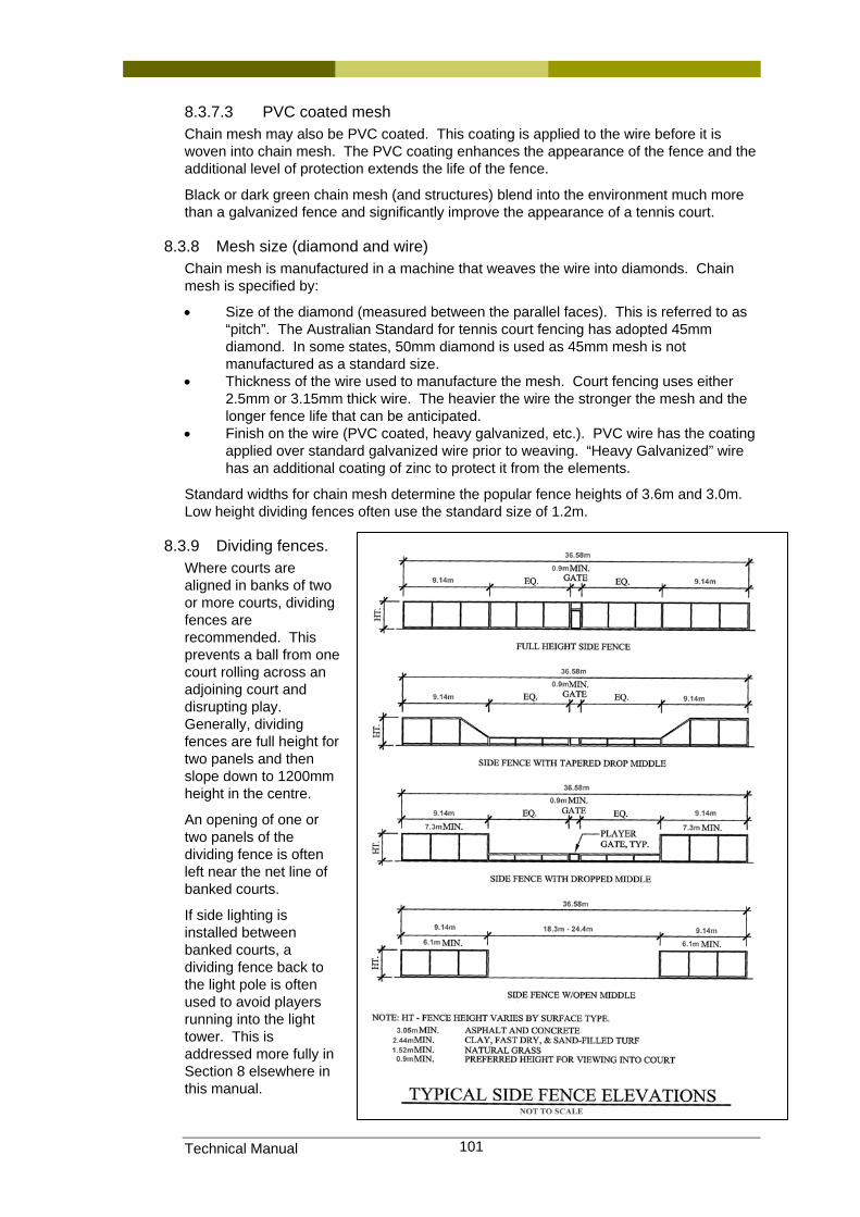
Technical Manual 101
8.3.7.3 PVC coated mesh Chain mesh may also be PVC coated. This coating is applied to the wire before it is woven into chain mesh. The PVC coating enhances the appearance of the fence and the additional level of protection extends the life of the fence.
Black or dark green chain mesh (and structures) blend into the environment much more than a galvanized fence and significantly improve the appearance of a tennis court.
8.3.8 Mesh size (diamond and wire) Chain mesh is manufactured in a machine that weaves the wire into diamonds. Chain mesh is specified by:
• Size of the diamond (measured between the parallel faces). This is referred to as “pitch”. The Australian Standard for tennis court fencing has adopted 45mm diamond. In some states, 50mm diamond is used as 45mm mesh is not manufactured as a standard size.
• Thickness of the wire used to manufacture the mesh. Court fencing uses either 2.5mm or 3.15mm thick wire. The heavier the wire the stronger the mesh and the longer fence life that can be anticipated.
• Finish on the wire (PVC coated, heavy galvanized, etc.). PVC wire has the coating applied over standard galvanized wire prior to weaving. “Heavy Galvanized” wire has an additional coating of zinc to protect it from the elements.
Standard widths for chain mesh determine the popular fence heights of 3.6m and 3.0m. Low height dividing fences often use the standard size of 1.2m.
8.3.9 Dividing fences. Where courts are aligned in banks of two or more courts, dividing fences are recommended. This prevents a ball from one court rolling across an adjoining court and disrupting play. Generally, dividing fences are full height for two panels and then slope down to 1200mm height in the centre.
An opening of one or two panels of the dividing fence is often left near the net line of banked courts.
If side lighting is installed between banked courts, a dividing fence back to the light pole is often used to avoid players running into the light tower. This is addressed more fully in Section 8 elsewhere in this manual.
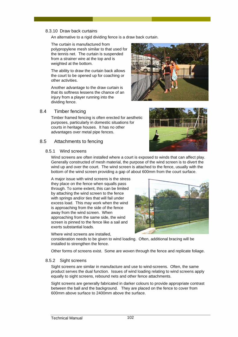
Technical Manual 102
8.3.10 Draw back curtains An alternative to a rigid dividing fence is a draw back curtain.
The curtain is manufactured from polypropylene mesh similar to that used for the tennis net. The curtain is suspended from a strainer wire at the top and is weighted at the bottom.
The ability to draw the curtain back allows the court to be opened up for coaching or other activities.
Another advantage to the draw curtain is that its softness lessens the chance of an injury from a player running into the dividing fence.
8.4 Timber fencing Timber framed fencing is often erected for aesthetic purposes, particularly in domestic situations for courts in heritage houses. It has no other advantages over metal pipe fences.
8.5 Attachments to fencing
8.5.1 Wind screens Wind screens are often installed where a court is exposed to winds that can affect play. Generally constructed of mesh material, the purpose of the wind screen is to divert the wind up and over the court. The wind screen is attached to the fence, usually with the bottom of the wind screen providing a gap of about 600mm from the court surface.
A major issue with wind screens is the stress they place on the fence when squalls pass through. To some extent, this can be limited by attaching the wind screen to the fence with springs and/or ties that will fail under excess load. This may work when the wind is approaching from the side of the fence away from the wind screen. When approaching from the same side, the wind screen is pinned to the fence like a sail and exerts substantial loads.
Where wind screens are installed, consideration needs to be given to wind loading. Often, additional bracing will be installed to strengthen the fence.
Other forms of screens exist. Some are woven through the fence and replicate foliage.
8.5.2 Sight screens Sight screens are similar in manufacture and use to wind-screens. Often, the same product serves the dual function. Issues of wind loading relating to wind screens apply equally to sight screens, rebound nets and other fence attachments.
Sight screens are generally fabricated in darker colours to provide appropriate contrast between the ball and the background. They are placed on the fence to cover from 600mm above surface to 2400mm above the surface.

Technical Manual 103
8.6 Maintenance and repair of fencing Routine maintenance should include a safety check of the fence mesh, periodic tightening and lubrication of gate hinges, checking fence fittings for loose bolts, checking tension of strainer wires, etc.
Ties should be checked to ensure sharp edges do not present as a scratch hazard.
Chain mesh should be checked to ensure it is not curling up to allow balls to leave the court.
8.7 Information sources, Standards and Codes. At time of writing, a draft Australian Standard is being prepared.
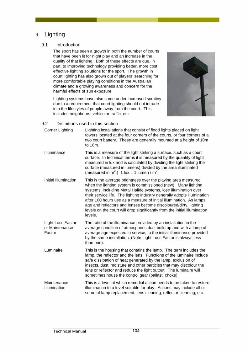
Technical Manual 104
9 Lighting
9.1 Introduction The sport has seen a growth in both the number of courts that have been lit for night play and an increase in the quality of that lighting. Both of these effects are due, in part, to improving technology providing better, more cost effective lighting solutions for the sport. The growth in court lighting has also grown out of players’ searching for more comfortable playing conditions in the Australian climate and a growing awareness and concern for the harmful effects of sun exposure.
Lighting systems have also come under increased scrutiny due to a requirement that court lighting should not intrude into the lifestyles of people away from the court. This includes neighbours, vehicular traffic, etc.
9.2 Definitions used in this section Corner Lighting Lighting installations that consist of flood lights placed on light
towers located at the four corners of the courts, or four corners of a two court battery. These are generally mounted at a height of 10m to 18m.
Illuminance This is a measure of the light striking a surface, such as a court surface. In technical terms it is measured by the quantity of light measured in lux and is calculated by dividing the light striking the surface (measured in lumens) divided by the area illuminated (measured in m2.) 1 lux = 1 lumen / m2.
Initial Illumination This is the average brightness over the playing area measured when the lighting system is commissioned (new). Many lighting systems, including Metal Halide systems, lose illumination over their service life. The lighting industry generally adopts illumination after 100 hours use as a measure of initial illumination. As lamps age and reflectors and lenses become discoloured/dirty, lighting levels on the court will drop significantly from the initial illumination levels.
Light Loss Factor or Maintenance Factor
The ratio of the illuminance provided by an installation in the average condition of atmospheric dust build up and with a lamp of average age expected in service, to the initial illuminance provided by the same installation. (Note Light Loss Factor is always less than one).
Luminaire This is the housing that contains the lamp. The term includes the lamp, the reflector and the lens. Functions of the luminaire include safe dissipation of heat generated by the lamp, exclusion of insects, dust, moisture and other particles that may discolour the lens or reflector and reduce the light output. The luminaire will sometimes house the control gear (ballast, choke).
Maintenance Illumination
This is a level at which remedial action needs to be taken to restore illumination to a level suitable for play. Actions may include all or some of lamp replacement, lens cleaning, reflector cleaning, etc.
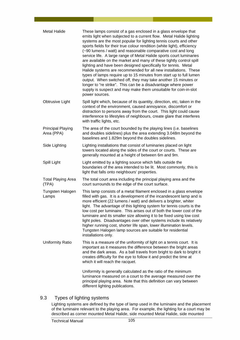
Technical Manual 105
Metal Halide These lamps consist of a gas enclosed in a glass envelope that emits light when subjected to a current flow. Metal Halide lighting systems are the most popular for lighting tennis courts and other sports fields for their true colour rendition (white light), efficiency (~90 lumens / watt) and reasonable comparative cost and long service life. A large range of Metal Halide sports court luminaries are available on the market and many of these tightly control spill lighting and have been designed specifically for tennis. Metal Halide systems are recommended for all new installations. These types of lamps require up to 15 minutes from start up to full lumen output. When switched off, they may take another 15 minutes or longer to “re strike”. This can be a disadvantage where power supply is suspect and may make them unsuitable for coin-in-slot power sources.
Obtrusive Light Spill light which, because of its quantity, direction, etc, taken in the context of the environment, caused annoyance, discomfort or distraction to persons away from the court. This light could cause interference to lifestyles of neighbours, create glare that interferes with traffic lights, etc.
Principal Playing Area (PPA)
The area of the court bounded by the playing lines (i.e. baselines and doubles sidelines) plus the area extending 3.048m beyond the baselines and 1.829m beyond the doubles sidelines.
Side Lighting Lighting installations that consist of luminaries placed on light towers located along the sides of the court or courts. These are generally mounted at a height of between 6m and 9m.
Spill Light Light emitted by a lighting source which falls outside the boundaries of the area intended to be lit. Most commonly, this is light that falls onto neighbours’ properties.
Total Playing Area (TPA)
The total court area including the principal playing area and the court surrounds to the edge of the court surface.
Tungsten Halogen Lamps
This lamp consists of a metal filament enclosed in a glass envelope filled with gas. It is a development of the incandescent lamp and is more efficient (22 lumens / watt) and delivers a brighter, whiter light. The advantage of this lighting system for tennis courts is the low cost per luminaire. This arises out of both the lower cost of the luminaire and its smaller size allowing it to be fixed using low cost light poles. Disadvantages over other systems include its relatively higher running cost, shorter life span, lower illumination levels. Tungsten Halogen lamp sources are suitable for residential installations only.
Uniformity Ratio This is a measure of the uniformity of light on a tennis court. It is important as it measures the difference between the bright areas and the dark areas. As a ball travels from bright to dark to bright it creates difficulty for the eye to follow it and predict the time at which it will reach the racquet. Uniformity is generally calculated as the ratio of the minimum luminance measured on a court to the average measured over the principal playing area. Note that this definition can vary between different lighting publications.
9.3 Types of lighting systems Lighting systems are defined by the type of lamp used in the luminaire and the placement of the luminaire relevant to the playing area. For example, the lighting for a court may be described as corner mounted Metal Halide, side mounted Metal Halide, side mounted
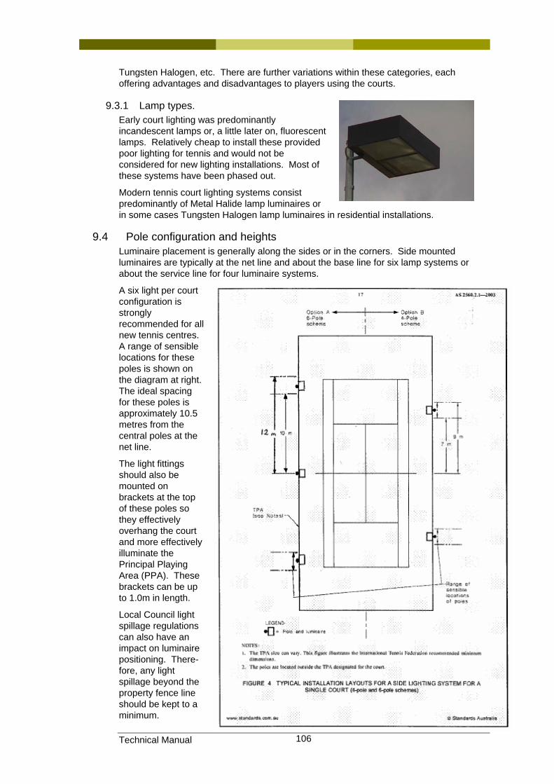
Technical Manual 106
Tungsten Halogen, etc. There are further variations within these categories, each offering advantages and disadvantages to players using the courts.
9.3.1 Lamp types. Early court lighting was predominantly incandescent lamps or, a little later on, fluorescent lamps. Relatively cheap to install these provided poor lighting for tennis and would not be considered for new lighting installations. Most of these systems have been phased out.
Modern tennis court lighting systems consist predominantly of Metal Halide lamp luminaires or in some cases Tungsten Halogen lamp luminaires in residential installations.
9.4 Pole configuration and heights Luminaire placement is generally along the sides or in the corners. Side mounted luminaires are typically at the net line and about the base line for six lamp systems or about the service line for four luminaire systems.
A six light per court configuration is strongly recommended for all new tennis centres. A range of sensible locations for these poles is shown on the diagram at right. The ideal spacing for these poles is approximately 10.5 metres from the central poles at the net line.
The light fittings should also be mounted on brackets at the top of these poles so they effectively overhang the court and more effectively illuminate the Principal Playing Area (PPA). These brackets can be up to 1.0m in length.
Local Council light spillage regulations can also have an impact on luminaire positioning. There-fore, any light spillage beyond the property fence line should be kept to a minimum.
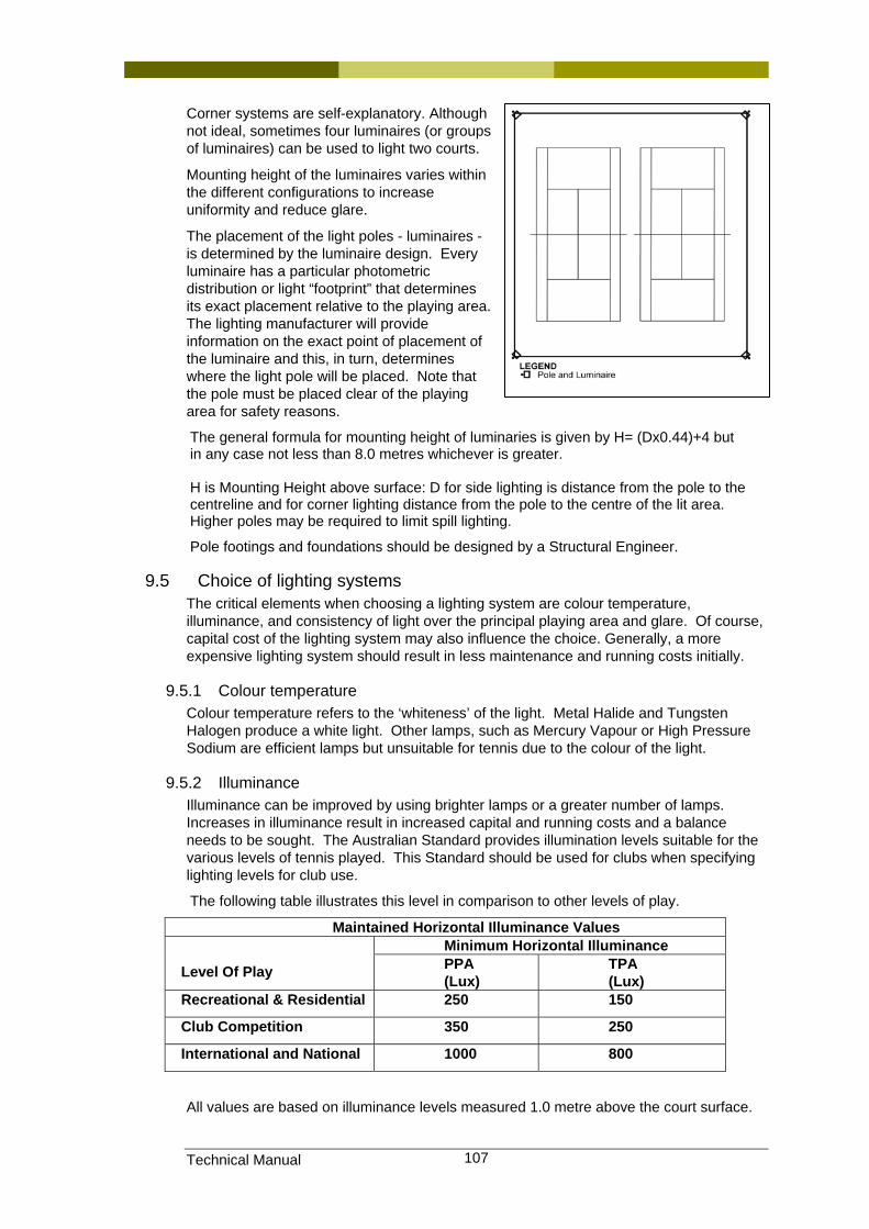
Technical Manual 107
Corner systems are self-explanatory. Although not ideal, sometimes four luminaires (or groups of luminaires) can be used to light two courts.
Mounting height of the luminaires varies within the different configurations to increase uniformity and reduce glare.
The placement of the light poles - luminaires - is determined by the luminaire design. Every luminaire has a particular photometric distribution or light “footprint” that determines its exact placement relative to the playing area. The lighting manufacturer will provide information on the exact point of placement of the luminaire and this, in turn, determines where the light pole will be placed. Note that the pole must be placed clear of the playing area for safety reasons.
The general formula for mounting height of luminaries is given by H= (Dx0.44)+4 but in any case not less than 8.0 metres whichever is greater. H is Mounting Height above surface: D for side lighting is distance from the pole to the centreline and for corner lighting distance from the pole to the centre of the lit area. Higher poles may be required to limit spill lighting.
Pole footings and foundations should be designed by a Structural Engineer.
9.5 Choice of lighting systems The critical elements when choosing a lighting system are colour temperature, illuminance, and consistency of light over the principal playing area and glare. Of course, capital cost of the lighting system may also influence the choice. Generally, a more expensive lighting system should result in less maintenance and running costs initially.
9.5.1 Colour temperature Colour temperature refers to the ‘whiteness’ of the light. Metal Halide and Tungsten Halogen produce a white light. Other lamps, such as Mercury Vapour or High Pressure Sodium are efficient lamps but unsuitable for tennis due to the colour of the light.
9.5.2 Illuminance Illuminance can be improved by using brighter lamps or a greater number of lamps. Increases in illuminance result in increased capital and running costs and a balance needs to be sought. The Australian Standard provides illumination levels suitable for the various levels of tennis played. This Standard should be used for clubs when specifying lighting levels for club use.
The following table illustrates this level in comparison to other levels of play.
Maintained Horizontal Illuminance Values Minimum Horizontal Illuminance
Level Of Play PPA (Lux)
TPA (Lux)
Recreational & Residential 250 150
Club Competition 350 250
International and National 1000 800
All values are based on illuminance levels measured 1.0 metre above the court surface.
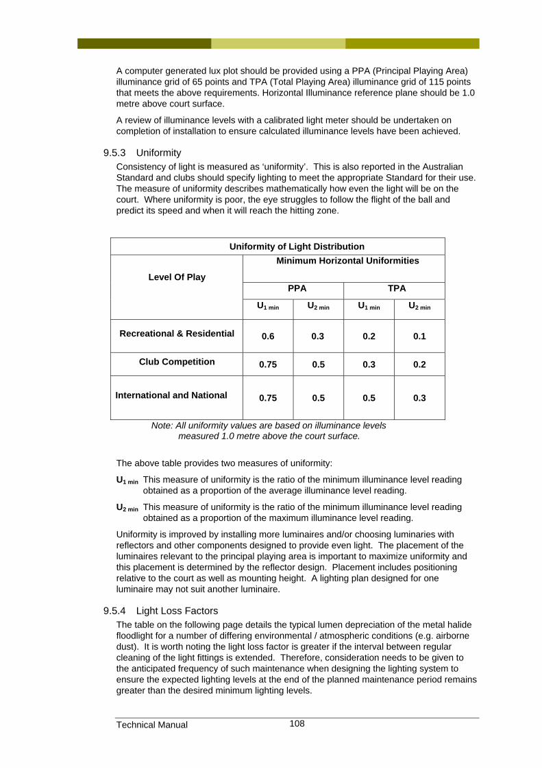
Technical Manual 108
A computer generated lux plot should be provided using a PPA (Principal Playing Area) illuminance grid of 65 points and TPA (Total Playing Area) illuminance grid of 115 points that meets the above requirements. Horizontal Illuminance reference plane should be 1.0 metre above court surface.
A review of illuminance levels with a calibrated light meter should be undertaken on completion of installation to ensure calculated illuminance levels have been achieved.
9.5.3 Uniformity Consistency of light is measured as ‘uniformity’. This is also reported in the Australian Standard and clubs should specify lighting to meet the appropriate Standard for their use. The measure of uniformity describes mathematically how even the light will be on the court. Where uniformity is poor, the eye struggles to follow the flight of the ball and predict its speed and when it will reach the hitting zone.
Uniformity of Light Distribution Minimum Horizontal Uniformities
PPA TPA
Level Of Play
U1 min U2 min U1 min U2 min
Recreational & Residential 0.6 0.3 0.2 0.1
Club Competition 0.75 0.5 0.3 0.2
International and National 0.75 0.5 0.5 0.3
Note: All uniformity values are based on illuminance levels measured 1.0 metre above the court surface.
The above table provides two measures of uniformity:
U1 min This measure of uniformity is the ratio of the minimum illuminance level reading obtained as a proportion of the average illuminance level reading.
U2 min This measure of uniformity is the ratio of the minimum illuminance level reading obtained as a proportion of the maximum illuminance level reading.
Uniformity is improved by installing more luminaires and/or choosing luminaries with reflectors and other components designed to provide even light. The placement of the luminaires relevant to the principal playing area is important to maximize uniformity and this placement is determined by the reflector design. Placement includes positioning relative to the court as well as mounting height. A lighting plan designed for one luminaire may not suit another luminaire.
9.5.4 Light Loss Factors The table on the following page details the typical lumen depreciation of the metal halide floodlight for a number of differing environmental / atmospheric conditions (e.g. airborne dust). It is worth noting the light loss factor is greater if the interval between regular cleaning of the light fittings is extended. Therefore, consideration needs to be given to the anticipated frequency of such maintenance when designing the lighting system to ensure the expected lighting levels at the end of the planned maintenance period remains greater than the desired minimum lighting levels.
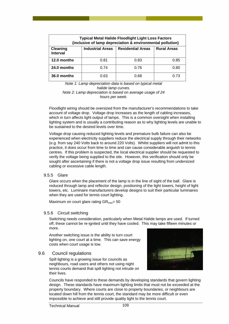
Technical Manual 109
Typical Metal Halide Floodlight Light Loss Factors (inclusive of lamp depreciation & environmental pollution)
Cleaning Interval
Industrial Areas Residential Areas Rural Areas
12.0 months 0.81 0.83 0.85
24.0 months 0.74 0.76 0.80
36.0 months 0.63 0.68 0.73
Note 1: Lamp depreciation data is based on typical metal halide lamp curves.
Note 2: Lamp depreciation is based on average usage of 24 hours per week.
Floodlight wiring should be oversized from the manufacturer’s recommendations to take account of voltage drop. Voltage drop increases as the length of cabling increases, which in turn affects light output of lamps. This is a common oversight when installing lighting system and is usually a contributing reason as to why lighting levels are unable to be sustained to the desired levels over time.
Voltage drop causing reduced lighting levels and premature bulb failure can also be experienced when electricity suppliers reduce the electrical supply through their networks (e.g. from say 240 Volts back to around 220 Volts). Whilst suppliers will not admit to this practice, it does occur from time to time and can cause considerable anguish to tennis centres. If this problem is suspected, the local electrical supplier should be requested to verify the voltage being supplied to the site. However, this verification should only be sought after ascertaining if there is not a voltage drop issue resulting from undersized cabling or excessive cable length.
9.5.5 Glare Glare occurs when the placement of the lamp is in the line of sight of the ball. Glare is reduced through lamp and reflector design, positioning of the light towers, height of light towers, etc. Luminaire manufacturers develop designs to suit their particular luminaires when they are used for tennis court lighting.
Maximum on court glare rating GRmax= 50
9.5.6 Circuit switching Switching needs consideration, particularly when Metal Halide lamps are used. If turned off, these cannot be re-ignited until they have cooled. This may take fifteen minutes or more.
Another switching issue is the ability to turn court lighting on, one court at a time. This can save energy costs when court usage is low.
9.6 Council regulations Spill lighting is a growing issue for councils as neighbours, road users and others not using night tennis courts demand that spill lighting not intrude on their lives.
Councils have responded to these demands by developing standards that govern lighting design. These standards have maximum lighting limits that must not be exceeded at the property boundary. Where courts are close to property boundaries, or neighbours are located down hill from the tennis court, the standard may be more difficult or even impossible to achieve and still provide quality light to the tennis court.
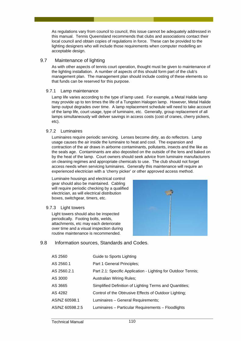
Technical Manual 110
As regulations vary from council to council, this issue cannot be adequately addressed in this manual. Tennis Queensland recommends that clubs and associations contact their local council and obtain copies of regulations in force. These can be provided to the lighting designers who will include those requirements when computer modelling an acceptable design.
9.7 Maintenance of lighting As with other aspects of tennis court operation, thought must be given to maintenance of the lighting installation. A number of aspects of this should form part of the club’s management plan. The management plan should include costing of these elements so that funds can be reserved for this purpose.
9.7.1 Lamp maintenance Lamp life varies according to the type of lamp used. For example, a Metal Halide lamp may provide up to ten times the life of a Tungsten Halogen lamp. However, Metal Halide lamp output degrades over time. A lamp replacement schedule will need to take account of the lamp life, court usage, type of luminaire, etc. Generally, group replacement of all lamps simultaneously will deliver savings in access costs (cost of cranes, cherry pickers, etc).
9.7.2 Luminaires Luminaires require periodic servicing. Lenses become dirty, as do reflectors. Lamp usage causes the air inside the luminaire to heat and cool. The expansion and contraction of the air draws in airborne contaminants, pollutants, insects and the like as the seals age. Contaminants are also deposited on the outside of the lens and baked on by the heat of the lamp. Court owners should seek advice from luminaire manufacturers on cleaning regimes and appropriate chemicals to use. The club should not forget access needs when servicing luminaires. Generally this maintenance will require an experienced electrician with a ‘cherry picker’ or other approved access method.
Luminaire housings and electrical control gear should also be maintained. Cabling will require periodic checking by a qualified electrician, as will electrical distribution boxes, switchgear, timers, etc.
9.7.3 Light towers Light towers should also be inspected periodically. Footing bolts, welds, attachments, etc may each deteriorate over time and a visual inspection during routine maintenance is recommended.
9.8 Information sources, Standards and Codes.
AS 2560 Guide to Sports Lighting
AS 2560.1 Part 1 General Principles;
AS 2560.2.1 Part 2.1: Specific Application - Lighting for Outdoor Tennis;
AS 3000 Australian Wiring Rules;
AS 3665 Simplified Definition of Lighting Terms and Quantities;
AS 4282 Control of the Obtrusive Effects of Outdoor Lighting;
AS/NZ 60598.1 Luminaires – General Requirements;
AS/NZ 60598.2.5 Luminaires – Particular Requirements – Floodlights

Technical Manual 111
Tennis Australia Technical Instruction - Lighting for Outdoor Tennis
9.9 Typical Suppliers • Hamilton - LSI Lighting Systems phone number (07) 3368 0200 • Moon Lighting phone number (07) 3621 9275 • Sylvannia Lighting phone number (07) 3034 8600 • Spectra Lighting phone number (07) 3335 3500
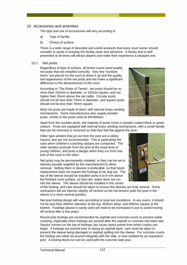
Technical Manual 112
10 Accessories and amenities The type and use of accessories will very according to
a] Type of facility
b] Choice of surface
There is a wide range of desirable and useful products that every court owner should consider to assist in keeping the facility clean and attractive. A facility that is well presented at all times will attract players and make their experience a pleasant one.
10.1 Net posts Regardless of type of surface, all tennis courts need quality net posts that are installed correctly. Very few ‘furniture items” are placed on the court to dress it up and the quality and appearance of the net posts and net make a significant difference to the attractiveness of the court.
According to ‘The Rules of Tennis’, net posts should be no more than 152mm in diameter, or 152mm square, and not higher than 25mm above the net cable. Circular posts should not be less than 73mm in diameter, and square posts should not be less than 76mm square.
Most net posts are made of steel, with internal brass winding mechanisms. Some manufacturers also supply wooden posts, similar to the posts used at Wimbledon.
Apart from the wooden posts, the majority of posts come in powder coated black or green colours. Posts are equipped with internal brass winding mechanisms, with a small handle that can be removed or reversed so that they fold flat against the post.
Older type winders that jut out from the post are a safety hazard, and are not recommended. This is particularly the case when children’s coaching classes are conducted. The older winders protrude from the post at the head level of young children, and pose a danger when they run from one end of the court to the other.
Net posts may be permanently installed, or they can be set in sleeves [usually supplied by the manufacturer] to allow removal. Setting them in sleeves is preferable, so that future replacement does not require the footings to be dug out. The top of the sleeve should be installed some 6 to 8 mm above the finished court surface, so that rain- water does not run into the sleeve. The sleeve should be installed in the centre of the footing, and care should be taken to ensure the sleeves are truly vertical. Some contractors will set sleeves slightly off vertical so the net tension pulls the post in the sleeve to a more vertical position.
Net post footing design will vary according to local soil conditions. In any event, it should not be less than 450mm diameter at the top, 650mm deep, and 600mm square at the bottom. Footings placed in sandy soils will need to be increased in size to avoid moving off vertical after a few years.
Round post footings are recommended for asphalt and concrete courts to prevent radial cracking, especially when footings are poured after the asphalt or concrete has been laid. Square corners on the top of footings can cause stress points from which cracks can begin. If footings are poured prior to laying an asphalt layer, care must be taken to prevent the sleeve being damaged or asphalt spilling into the sleeve. For concrete courts the footing can either be poured integrally with the slab, or else isolated by an expansion joint. A footing block-out can be used with the concrete slab pour.
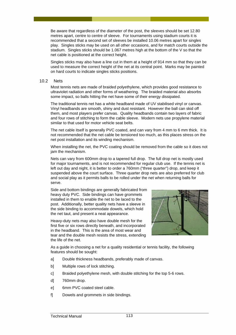
Technical Manual 113
Be aware that regardless of the diameter of the post, the sleeves should be set 12.80 metres apart, centre to centre of sleeve. For tournaments using stadium courts it is recommended that a second set of sleeves be installed 10.06 metres apart for singles play. Singles sticks may be used on all other occasions, and for match courts outside the stadium. Singles sticks should be 1.067 metres high at the bottom of the V so that the net cable is positioned at the correct height.
Singles sticks may also have a line cut in them at a height of 914 mm so that they can be used to measure the correct height of the net at its central point. Marks may be painted on hard courts to indicate singles sticks positions.
10.2 Nets Most tennis nets are made of braided polyethylene, which provides good resistance to ultraviolet radiation and other forms of weathering. The braided material also absorbs some impact, so balls hitting the net have some of their energy dissipated.
The traditional tennis net has a white headband made of UV stabilised vinyl or canvas. Vinyl headbands are smooth, shiny and dust resistant. However the ball can skid off them, and most players prefer canvas. Quality headbands contain two layers of fabric and four rows of stitching to form the cable sleeve. Modern nets use propylene material similar to that used for motor vehicle seat belts.
The net cable itself is generally PVC coated, and can vary from 4 mm to 6 mm thick. It is not recommended that the net cable be tensioned too much, as this places stress on the net post installation and its winding mechanism.
When installing the net, the PVC coating should be removed from the cable so it does not jam the mechanism.
Nets can vary from 600mm drop to a tapered full drop. The full drop net is mostly used for major tournaments, and is not recommended for regular club use. If the tennis net is left out day and night, it is better to order a 760mm (“three quarter”) drop, and keep it suspended above the court surface. Three quarter drop nets are also preferred for club and social play as it permits balls to be rolled under the net when returning balls for serve.
Side and bottom bindings are generally fabricated from heavy duty PVC. Side bindings can have grommets installed in them to enable the net to be laced to the post. Additionally, better quality nets have a sleeve in the side binding to accommodate dowels, which hold the net taut, and present a neat appearance.
Heavy-duty nets may also have double mesh for the first five or six rows directly beneath, and incorporated in the headband. This is the area of most wear and tear and the double mesh resists the stress, extending the life of the net.
As a guide in choosing a net for a quality residential or tennis facility, the following features should be sought:
a] Double thickness headbands, preferably made of canvas.
b] Multiple rows of lock stitching.
c] Braided polyethylene mesh, with double stitching for the top 5-6 rows.
d] 760mm drop.
e] 6mm PVC coated steel cable.
f] Dowels and grommets in side bindings.
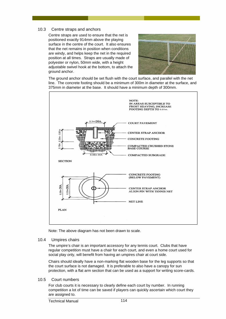
Technical Manual 114
10.3 Centre straps and anchors Centre straps are used to ensure that the net is positioned exactly 914mm above the playing surface in the centre of the court. It also ensures that the net remains in position when conditions are windy, and helps keep the net in the required position at all times. Straps are usually made of polyester or nylon, 50mm wide, with a height adjustable swivel hook at the bottom, to attach the ground anchor.
The ground anchor should be set flush with the court surface, and parallel with the net line. The concrete footing should be a minimum of 300m in diameter at the surface, and 375mm in diameter at the base. It should have a minimum depth of 300mm.
Note: The above diagram has not been drawn to scale.
10.4 Umpires chairs The umpire’s chair is an important accessory for any tennis court. Clubs that have regular competition must have a chair for each court, and even a home court used for social play only, will benefit from having an umpires chair at court side.
Chairs should ideally have a non-marking flat wooden base for the leg supports so that the court surface is not damaged. It is preferable to also have a canopy for sun protection, with a flat arm section that can be used as a support for writing score-cards.
10.5 Court numbers For club courts it is necessary to clearly define each court by number. In running competition a lot of time can be saved if players can quickly ascertain which court they are assigned to.
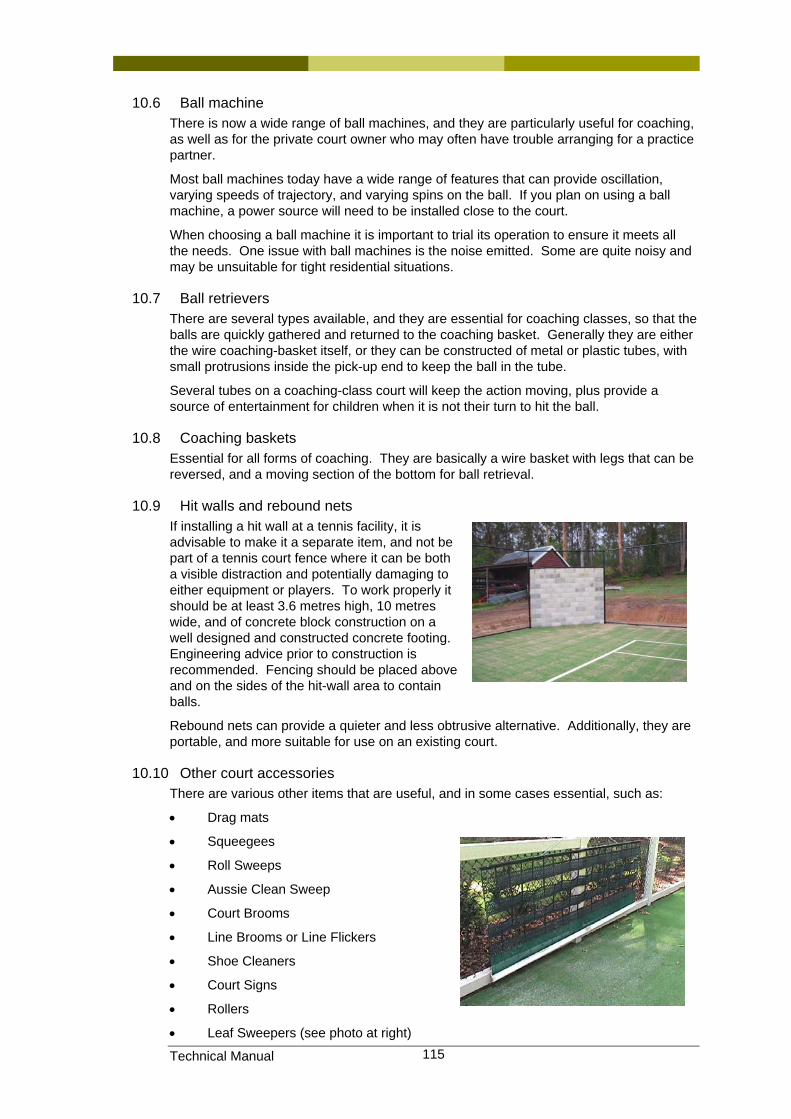
Technical Manual 115
10.6 Ball machine There is now a wide range of ball machines, and they are particularly useful for coaching, as well as for the private court owner who may often have trouble arranging for a practice partner.
Most ball machines today have a wide range of features that can provide oscillation, varying speeds of trajectory, and varying spins on the ball. If you plan on using a ball machine, a power source will need to be installed close to the court.
When choosing a ball machine it is important to trial its operation to ensure it meets all the needs. One issue with ball machines is the noise emitted. Some are quite noisy and may be unsuitable for tight residential situations.
10.7 Ball retrievers There are several types available, and they are essential for coaching classes, so that the balls are quickly gathered and returned to the coaching basket. Generally they are either the wire coaching-basket itself, or they can be constructed of metal or plastic tubes, with small protrusions inside the pick-up end to keep the ball in the tube.
Several tubes on a coaching-class court will keep the action moving, plus provide a source of entertainment for children when it is not their turn to hit the ball.
10.8 Coaching baskets Essential for all forms of coaching. They are basically a wire basket with legs that can be reversed, and a moving section of the bottom for ball retrieval.
10.9 Hit walls and rebound nets If installing a hit wall at a tennis facility, it is advisable to make it a separate item, and not be part of a tennis court fence where it can be both a visible distraction and potentially damaging to either equipment or players. To work properly it should be at least 3.6 metres high, 10 metres wide, and of concrete block construction on a well designed and constructed concrete footing. Engineering advice prior to construction is recommended. Fencing should be placed above and on the sides of the hit-wall area to contain balls.
Rebound nets can provide a quieter and less obtrusive alternative. Additionally, they are portable, and more suitable for use on an existing court.
10.10 Other court accessories There are various other items that are useful, and in some cases essential, such as:
• Drag mats
• Squeegees
• Roll Sweeps
• Aussie Clean Sweep
• Court Brooms
• Line Brooms or Line Flickers
• Shoe Cleaners
• Court Signs
• Rollers
• Leaf Sweepers (see photo at right)

Technical Manual 116
• Score boards
• Court Benches
10.11 Off court accessories
Amongst items that should be considered are:
• Shade Shelters for spectators
• Rubbish Bins
• Drinking Fountains
• Seating for spectators
• Power outlets
• Hose connections
• Storage areas for court equipment
10.12 Security and safety A facility should have security lighting and a fencing design that limits access to the amenity.
An intercom or loudspeaker system will assist tournament play and lines of communication.
Other desirable features are nearby restrooms, changing facilities, and first-aid supplies, all of which can be incorporated in the clubhouse design.
10.13 Suppliers of tennis court accessories As with tennis court contractors, Tennis Queensland prefers not to recommend suppliers of tennis court accessories and equipment. Again, we prefer to recommend suppliers of such products that are members of the Sports Contractors Association. A complete list of these suppliers can be obtained by contacting this group or by searching their web site, (which is www.sportscontractors.com.au). From this list, some of the most “helpful” of these suppliers have been listed here for easy reference.
Grand Slam Sports Equipment
19 Deakin St
Brendale Q 4500
Jordin Sports
4/84 Newmarket Road
Windsor Q 4030
Play Hard Sports Equipment
24 Ern Harley Drive
West Burleigh Q 4220
Sportzing Court Care Services
Level 1 Unit 18, 1645 Ipswich Road
Rocklea Q 4106

Technical Manual 117
Multisport Concepts Pty Ltd
PO Box 2044
Burleigh DC Q 4220
Advantage Sports & Leisure
PO Box 573
Cairns Q 4870
Allsports Products Pty Ltd
PO Box 158B
Bungalow Q 4870
Sports Technology International Pty Ltd
PO Box 4260
Dandenong South VIC 3175
En Tout Cas
66 Keys Rd
Moorabbin VIC 3189
Raw Courts
[email protected] or phone 0411 242 272
10.14 Information sources, Standards and Codes. No standards exist for tennis facilities
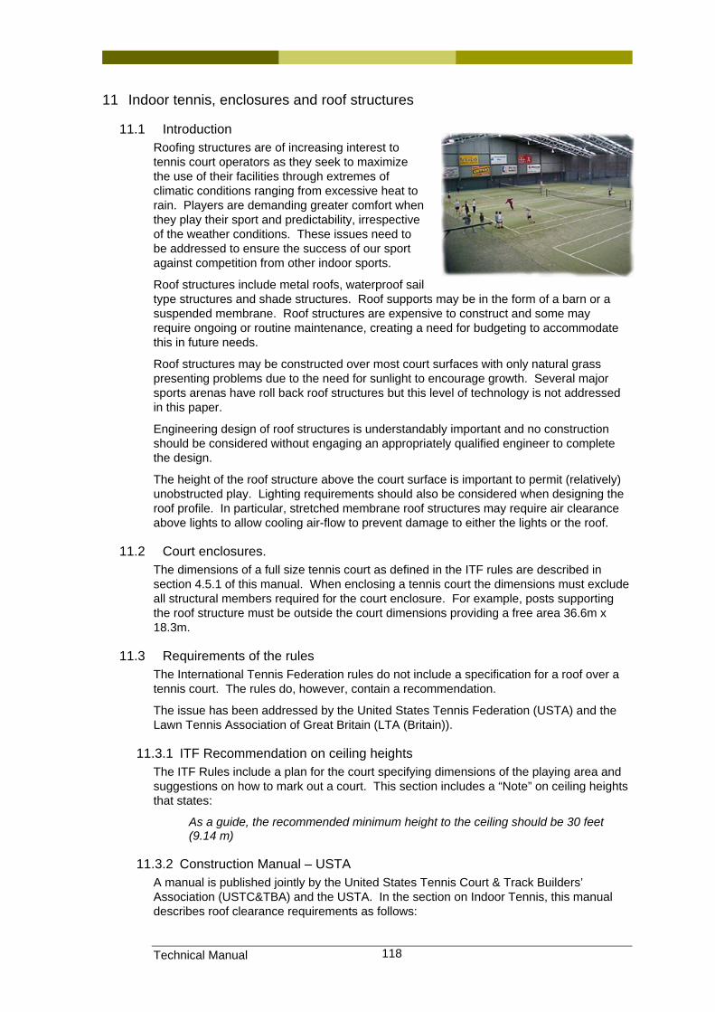
Technical Manual 118
11 Indoor tennis, enclosures and roof structures
11.1 Introduction Roofing structures are of increasing interest to tennis court operators as they seek to maximize the use of their facilities through extremes of climatic conditions ranging from excessive heat to rain. Players are demanding greater comfort when they play their sport and predictability, irrespective of the weather conditions. These issues need to be addressed to ensure the success of our sport against competition from other indoor sports.
Roof structures include metal roofs, waterproof sail type structures and shade structures. Roof supports may be in the form of a barn or a suspended membrane. Roof structures are expensive to construct and some may require ongoing or routine maintenance, creating a need for budgeting to accommodate this in future needs.
Roof structures may be constructed over most court surfaces with only natural grass presenting problems due to the need for sunlight to encourage growth. Several major sports arenas have roll back roof structures but this level of technology is not addressed in this paper.
Engineering design of roof structures is understandably important and no construction should be considered without engaging an appropriately qualified engineer to complete the design.
The height of the roof structure above the court surface is important to permit (relatively) unobstructed play. Lighting requirements should also be considered when designing the roof profile. In particular, stretched membrane roof structures may require air clearance above lights to allow cooling air-flow to prevent damage to either the lights or the roof.
11.2 Court enclosures. The dimensions of a full size tennis court as defined in the ITF rules are described in section 4.5.1 of this manual. When enclosing a tennis court the dimensions must exclude all structural members required for the court enclosure. For example, posts supporting the roof structure must be outside the court dimensions providing a free area 36.6m x 18.3m.
11.3 Requirements of the rules The International Tennis Federation rules do not include a specification for a roof over a tennis court. The rules do, however, contain a recommendation.
The issue has been addressed by the United States Tennis Federation (USTA) and the Lawn Tennis Association of Great Britain (LTA (Britain)).
11.3.1 ITF Recommendation on ceiling heights The ITF Rules include a plan for the court specifying dimensions of the playing area and suggestions on how to mark out a court. This section includes a “Note” on ceiling heights that states:
As a guide, the recommended minimum height to the ceiling should be 30 feet (9.14 m)
11.3.2 Construction Manual – USTA A manual is published jointly by the United States Tennis Court & Track Builders’ Association (USTC&TBA) and the USTA. In the section on Indoor Tennis, this manual describes roof clearance requirements as follows:
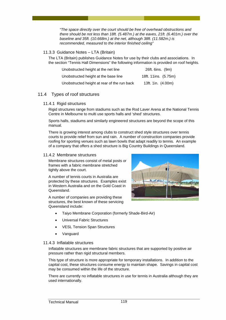
Technical Manual 119
“The space directly over the court should be free of overhead obstructions and there should be not less than 18ft. (5.487m.) at the eaves, 21ft. (6.401m.) over the baseline and 35ft. (10.668m.) at the net, although 38ft. (11.582m.) is recommended, measured to the interior finished ceiling”
11.3.3 Guidance Notes – LTA (Britain) The LTA (Britain) publishes Guidance Notes for use by their clubs and associations. In the section “Tennis Hall Dimensions” the following information is provided on roof heights.
Unobstructed height at the net line 26ft. 6ins. (9m)
Unobstructed height at the base line 18ft. 11ins. (5.75m)
Unobstructed height at rear of the run back 13ft. 1in. (4.00m)
11.4 Types of roof structures
11.4.1 Rigid structures Rigid structures range from stadiums such as the Rod Laver Arena at the National Tennis Centre in Melbourne to multi use sports halls and ‘shed’ structures.
Sports halls, stadiums and similarly engineered structures are beyond the scope of this manual.
There is growing interest among clubs to construct shed style structures over tennis courts to provide relief from sun and rain. A number of construction companies provide roofing for sporting venues such as lawn bowls that adapt readily to tennis. An example of a company that offers a shed structure is Big Country Buildings in Queensland.
11.4.2 Membrane structures Membrane structures consist of metal posts or frames with a fabric membrane stretched tightly above the court.
A number of tennis courts in Australia are protected by these structures. Examples exist in Western Australia and on the Gold Coast in Queensland.
A number of companies are providing these structures, the best known of these servicing Queensland include:
• Taiyo Membrane Corporation (formerly Shade-Bird-Air)
• Universal Fabric Structures
• VESL Tension Span Structures
• Vanguard
11.4.3 Inflatable structures Inflatable structures are membrane fabric structures that are supported by positive air pressure rather than rigid structural members.
This type of structure is more appropriate for temporary installations. In addition to the capital cost, these structures consume energy to maintain shape. Savings in capital cost may be consumed within the life of the structure.
There are currently no inflatable structures in use for tennis in Australia although they are used internationally.
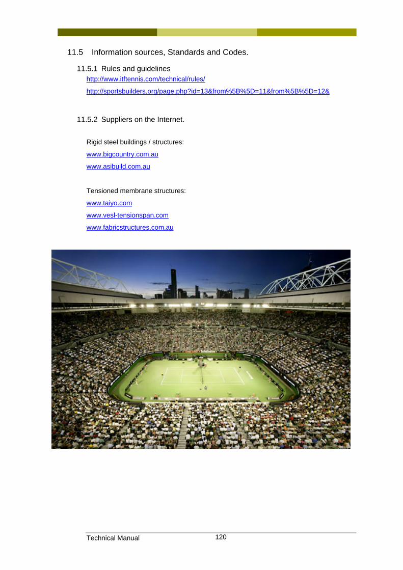
Technical Manual 120
11.5 Information sources, Standards and Codes.
11.5.1 Rules and guidelines http://www.itftennis.com/technical/rules/
http://sportsbuilders.org/page.php?id=13&from%5B%5D=11&from%5B%5D=12&
11.5.2 Suppliers on the Internet.
Rigid steel buildings / structures:
www.bigcountry.com.au
www.asibuild.com.au
Tensioned membrane structures:
www.taiyo.com
www.vesl-tensionspan.com
www.fabricstructures.com.au
Technical Manual 121
12 Club facilities
12.1 Introduction The size, location, and layout for a clubhouse will vary from site to site, depending on a number of factors:
• Number of courts planned for the tennis facility
• Land topography
• Type of facility and whether there is a shared use with another sport
• Other specific needs of the club membership
12.1.1 Layout There are some fundamental requirements however. The clubhouse preferably should be centrally located to the courts, and close to the parking area. The manager's office and reception areas should adjoin, and both of these areas have a clear view of as many courts as possible.
The positioning of a pro-shop should be adjoining the reception area, so that anyone entering or leaving the shop passes by the reception area. Some additional video security may also be necessary to adequately supervise these areas. Adequate storage areas for supplies to the reception area and pro-shop should also be positioned in an adjacent location so that these areas can be quickly serviced. The manager's or professional's office should have sufficient room for files, and a small meeting area.
A kitchen, cafe, and players' lounge, opening out onto a large covered deck, with views over the courts is also most desirable. The kitchen and cafe should be equipped to supply a variety of food similar to a coffee shop. During tournaments this area will receive a constant and heavy amount of use, and provision should be made to spill out onto a covered deck and/or adjoining shaded areas that overlook the courts.
A tournament office should be located so that as many courts as possible are in view. Provision should be made for a large notice board on an external wall of the tournament office where draw-sheets can be pinned, so that players and spectators can examine the sheets without entering the tournament box itself. Sufficient showers and toilets and perhaps lockers should be incorporated, to cater for the size and type of facility.
Tennis Queensland’s Technical Services Department have a library of club house designs of various sizes and configurations. Please feel free to contact them any time to see if they have a design that might suit your needs. Otherwise, they can produce an indicative design that will suit the layout of your facility and ensure the key relationships between the car parking areas and the positioning of the courts is reflected in the design, thereby maximise the effectiveness and usability of your club house.
12.1.2 Size requirements As a general guide, a clubhouse to adequately provide sufficient amenities for a 10-12 court centre should have a total area of 450 sq metres. It would include the following spaces as a minimum:
Lounge, club rooms, cafe area 170 sq m. Kitchen area 30 sq m. Pro-shop 50 sq m. Manager's Office 16 sq m. Bathrooms 50 sq m. Store Rooms 36 sq m. Deck 90 sq m. Tournament Box 20 sq m.

Technical Manual 122
12.1.3 Other provisions Provision should be made for disabled access to all areas, and a disabled toilet installed within the toilet block. Wheelchair tennis is becoming more popular, and thought should be given to making court access available, so that a wheelchair tennis event could be conducted.
Public telephones and sources of drinking water should be available. A public address system is essential to the running of tournaments.
As with all building projects, the final design will need to be completed by registered professional designers recognised by the local government authority having building and planning jurisdiction over the site. Development and Building Approvals will be required from the relevant local government authority before any construction works can commence on site, along with the required inspections and approvals obtained during construction to allow lawful occupation of the building on completion.
12.2 Information sources, Standards and Codes.
Technical Manual 123
13 Managing a project
13.1 Introduction Project Management of a complete tennis complex is a specialised role that generally requires the engagement of a professional manager with at least a substantial understanding of all the topics covered in this manual. Alternatively, a person with non-tennis based Project Management skills (i.e. a person with a professional background in the construction industry, such as an engineer) could be capable of undertaking this role provided they have access to other people with this tennis specific knowledge who can assist and/or review project progress at key points of the project.
Similarly, smaller projects, such as repairs and resurfacing, or maybe even the construction of a single court could be undertaken by owners or club members providing they have also obtained the right technical guidance from the outset and along the way.
13.2 Definitions used in this section Bill of Quantities or a Schedule of Rates
A list of all the items of work required in a project provided to all contractors pricing this project to make comparison of all quotes received an easier process
Defects Liability Period
A nominated timeframe included in a building works contract during which the contractor is obliged to return to site to rectify any defective works identified after Practical Completion has been achieved
Geotechnical Engineer
An professional engineer who specialises in analysing soil conditions and subsequently determining what sort of base construction is required for a tennis court (or foundations for a house or other structure)
“hold points” Nominated time/s at which no further works can proceed until all parties agree the works completed up to that stage of the works are in accordance with the specified requirements
Practical Completion The date when all parties agree the specified project works are completed to the point where they are fit for its intended use
Progress Payments Payments made by the owner to the contractor either on achievement of set project milestones or on a regular timeframe basis (i.e. fortnightly or monthly)
Retention Monies withheld from progress payments from the owner to the contractor as security that the contractor will complete the works and rectify any defects after Practical Completion has been achieved during the Defects Liability Period
Technical Specification
A document produced by the owner or the owner’s Project Manager or other consultants detailing the scope of works required and the minimum standards or requirements by which this work is to be completed.
Topographical Survey
A site map produced by a Surveyor showing the existing site levels, approximate contour levels and existing features to provide the contractor with an indication of the site works required prior to construction of the tennis court base
13.3 Obtaining technical guidance There are very few professional design groups who have this specialised expertise with regards to all aspects of a typical tennis court related project. Therefore, the best source
Technical Manual 124
of such information will generally be your local affiliated body in your state or territory (i.e. Tennis Queensland).
These bodies generally have a department which specialises in providing this expert advice as they have access to unique individuals who have been building or overseeing the construction of such facilities for 20 years or more. They may also include other vitally important professionals with a wealth of experience in specific aspects of tennis courts, such as Geotechnical Engineers, Electrical Engineers, Civil / Structural Engineers and court surfacing specialists.
13.4 Site investigation It is essential that the first consultant approached when contemplating the design and construction of a tennis court is a Geotechnical Engineer. This specialist consultant will undertake site investigations by means of drilling bore holes and taking soil samples around the proposed site to ascertain the existing soil conditions. The results of these samples and tests are then used to determine the structural requirements of the tennis court base to be constructed, depending upon the proposed playing surface.
Before any other design works can proceed, a Surveyor should be engaged to produce a topographical survey of the site. A topographical survey shows the existing levels over the site to determine the following:
• existing path of overland water flow so that this can be considered and incorporated into the design,
• the extent of earthworks that will be required to create a platform upon which the tennis court base can be constructed, and
• identify the exact location of any existing features on the site – such as trees, fences, buildings, concrete pathways, power supply lines, water meters, etc. to ascertain if any of these will have an impact on the proposed construction works (i.e. whether any of these sorts of structures may need to be demolished or relocated)
13.5 Preparing a technical specification Technical specifications for tennis court construction are again best left to those select few who possess an intimate knowledge of all aspects of tennis court construction, or for a Project Manager to assemble based on advice sourced from specialists in their field of expertise (e.g. an Electrical Engineer providing advice on flood lighting systems).
Again, the best source of such advice on preparing technical specifications will generally be your local affiliated body in your state or territory (i.e. Tennis Queensland).
A well prepared technical specification that clearly details the required scope of works will minimise the chances of there being any disputes during or at completion of construction as to what the intended scope of works was. This is by far the most common cause of disputes between owners and contractors (others generally relate to workmanship or payment issues).
It is highly recommended that the technical specification document is accompanied by a detailed Bill of Quantities or a Schedule of Rates. This document should itemise all the works required so that all contractors pricing this project are doing so on the same basis, thereby providing a basis upon which to compare the quotes received.
13.6 Inviting tenders from the construction industry Unfortunately, as with every other sector of the construction industry, there are a number of “shonky” contractors in the marketplace. There are a number of glorified concreting or landscaping firms passing themselves off as tennis court constructers with little understanding of the technical aspects of tennis court construction. Often the result of engaging these contractors is a tennis court or courts with inadequate base preparation leading to major structural failures and ongoing costly maintenance issues that become evident after only a relatively short period of time.

Technical Manual 125
So why do some people and clubs seem to continue finding themselves in this situation? Generally it is a question of money. These contractors will invariably offer to construct their courts at significantly lower prices than their more recognised and higher quality competitors. Given that many clubs struggle to raise funds to undertake such works, the temptation to minimise their outlay on such relatively large projects (for them) is often all too appealing. The old adage that “you only get what you pay for” is so very true when it comes to tennis court construction.
It is suggested that if you are looking for firms to tender or quote upon your new tennis court or complex, that time is taken to research the credentials and references of these firms. Arrangements should be made to inspect some of the contractor’s previous projects to get a feel for their quality and level of workmanship. The financial outlay for a tennis court is substantial, so the time should be taken to conduct this research before you hand over your hard earned money.
It is also recommended that contact be made with your state or territory division of the Sporting Contractors Association (ph. 1800 208 202 or www.sportscontractors.com.au) to obtain a list of tennis court contractors that are members of this group. Whilst membership of this association is still no guarantee that you will receive the quality court that you deserve, the risk of selecting a rogue contractor is greatly reduced. Members of this group are required to regularly demonstrate the quality of their workmanship to retain their membership status, and their peers are generally quick to ensure their collective reputations are not being tarnished by any individual in their ranks.
The same background checks recommended above should be carried out even if requesting a tender from members of these associations to ensure you are dealing with individuals or firms that you feel most comfortable in dealing with.
When requesting contractors to provide you with a quotation, it is recommended that you give them at least 2-3 weeks to review the project specifications and any other information you may be able to provide them with. This allows them sufficient time to review and comprehend all the documentation provided as well as obtain any prices they may need from their suppliers.
Consideration should be given to the reality that they may well be in the process of constructing another project somewhere else during business hours whilst preparing your quotation out of hours. Therefore, giving them this reasonable timeframe in which to prepare your quotation or tender allows them some flexibility in which to find the necessary time to devote to this exercise. Chances are that they may be quoting on more than one project at any time.
If you don’t give them sufficient time in which to prepare their tender, they will probably not absorb the information provided or they will err on the side of caution when preparing their quotation. As a result, your quote may not be as competitive as perhaps it could be and you may end up paying more for your tennis court/s than you could have – all for the sake of a week or two at this critical stage of your project.
If you have a project with a tight and finite budget, it may be prudent to prepare a Bill of Quantities or Schedule of Rates which covers the basic or minimum construction requirements that will safely fall within the budget. From this point, further items can be added to this base price on an option extra basis (like adding extras such as air conditioning or sporty wheels to a base model new car). This will provide you with the ability to choose the options that you can afford to add to your basic tennis court construction up to the limits of your budget.
Whether you are on a tight budget or not, a contingency allowance should always be set aside from the quotation price accepted. This will provide a buffer for the unexpected or accidentally forgotten items that always seem to crop up during any construction project. A safe allowance is normally around 5% of the accepted contract price, however lesser amounts can be safely used where there is minimal “in-ground” works required or the specification documents produced are considered to be of a high standard of quality.

Technical Manual 126
13.7 Choosing between tenders This process can be made considerably easier if all quotes are based on a clear and well detailed project specification and, as mentioned previously, a well compiled Bill of Quantities or a Schedule of Rates. If this is the case, the choice, if being based purely on cost, can be made much easier.
However, as discussed previously, consideration should also be given to the contractor’s performance on recent projects (based on their references), the demonstrated quality of their workmanship (as evidenced from inspections of previously completed projects) and your own impressions from communications up to this point (and references obtained) as to whether you feel comfortable dealing with each of these contractors.
Depending upon the emphasis placed on each of these criteria, the choice may be simple or very difficult. On larger projects, it is not uncommon for each of these criteria to be given a weighting (say 50% for price, 20% for previous performance / references, 20% for demonstrated workmanship and 10% for being able to work well with this contractor). The weightings for each of these items (and others that may be applicable to your project) can be modified to reflect the nature of the project and your own priorities.
Each tender submission is then marked against each of these weighted criteria so as to arrive at the “best” value for money offer. Having undertaken this exercise, it is possible that you may still be faced with a tough decision between two or more contractors. If this is the case, you may need to focus on the scores given to each of these contractors against the most heavily weighted selection criteria as a guide, as these are obviously your areas of main concern. Alternatively, you could interview each of these contractors again and discuss your key areas of concern with regards to their submission to either confirm or allay your fears in this regard. It may also provide some vital feedback to these tenderers as to where they may need to improve in order to secure future business for themselves.
There is nothing to say this same exercise cannot be undertaken on any size project – not just large projects. An individual tennis court for a home owner may be a relatively more stressful (financially and otherwise) undertaking than a complete complex may be for a wealthy developer. It may actually be beneficial to advise prospective tenderers that their submission is to be evaluated on criteria other than price alone, as they may take more time to address the way in which they approach you before, during and after this tendering process.
If you have engaged a project manager to oversee all stages of your project, they will devise their own methods of reviewing and recommending a tender submission to be accepted, generally along the lines of the process outlined above. Remember, the Project Manager will only make a recommendation as to who they think you should enter into a contract with to undertake your project, and it may well be beneficial to do your own review to see if you concur with their recommendation/s.
At the end of they day it is your decision, and it is one that you will have to feel comfortable with for a long time once it has been made. So take your time and choose wisely!
13.8 Contracts and project acceptance Once a decision has been made to accept a contractor’s quotation or tender, the next step is to advise them of your intention to accept their offer and advise any other contractor’s that their bids have been unsuccessful. This allows both the successful and unsuccessful tenderers to either begin planning and preparations to undertake your project or to move on and price another project without worrying about whether they might put themselves in a position where they end up with more work than they can physically handle at any one time.
Unless the quotation you are planning to accept has specifically nominated that it is conditional upon entering into a particular form of contract, the next step is to come to an agreement with that contractor on a set of contract conditions that you can both work with. If they have nominated a specific form of contract in their quotation, this needs to be
Technical Manual 127
taken into consideration when comparing this tender with others received. If there is a specific form of contract that you wish to use, this could be nominated in the project specification provided to contractors during the tender period.
There are three Australian Standard forms of contract available, AS 2124, AS 4000 and AS 4305, although these contracts are written predominantly with building contracts in mind. Other less commonly used Building Contracts include JCC, NPWC, QMBA and QBSA contracts. The Sports Contractors are currently considering the development of a standard form of contract that specifically relates to the construction of tennis courts and other sporting facilities, but this may still be some years away from being finalised.
13.9 Project supervision Unless you have absolute faith in the abilities of your contractor and trust them implicitly, or the owner has a good degree of knowledge about tennis court construction, it is recommended that owners engage someone with this ability to supervise the contractor’s work at various key points during construction. These intended key points or “hold points” should be identified in the project specification so that the contractor is aware they cannot proceed with any further works on the project until their works up to that point have been inspected and it is agreed these works have been completed to a satisfactory standard. Again, these standards should also be clearly described in the project specification.
An example of a typical tennis court project hold point would be the provision of soil compaction test results to demonstrate that the sub-base prepared meets the specified requirements and is therefore is suitable for subsequent base construction works to commence. Another example would be an inspection of the under slab plastic membrane, tied reinforcement mesh and edge formwork for compliance with the project specification prior to pouring and finishing of the concrete slab.
If for any reason, the works up to this stage are not of an acceptable standard, the contractor should be instructed to rectify this situation in accordance with the project specification requirements. The best placed person to make these inspections will be the person who wrote the specification documents relating to that aspect of the works, or an extremely competent project manager with a professional background relevant to the works they are inspecting. For example, the completed earthworks and associated test results should be reviewed and approved (or otherwise) by the Civil or Geotechnical Engineer who prepared the plans and specification for this aspect of the works (if required).
These checks should ensure that any potential cause of defects as a result of poor workmanship or building practices that may arise during construction are picked up along the way and rectified immediately before they become a much larger problem. In most cases, it will be far more cost effective for all concerned if such problems are picked up at this relatively early stage of a project rather than when works are complete – particularly if they are “in ground” problems that subsequently get “built over” in the natural course of events.
13.10 Progress payments and retentions Most tennis court contractors will request that progress payments be made when certain project milestones are reached or at recurring regular time intervals (i.e. fortnightly or monthly) rather than one lump sum at the completion of all works. This is considered to be a fair arrangement for all parties, as it provides the contractor with a degree of security that they are getting paid for the work they are doing and also assists their business cashflow (otherwise, a contractor could be out of pocket for many weeks or months for aspects of the works they have completed and paid for at the start of a project).
From a court owner’s point of view, it allows them to plan ahead for when these payments are required to be made. It also provides some leverage against the contractor to ensure they are completing all the works required to achieve each of these milestones.
Most contracts require that retention monies are set aside in each progress payment as a form of security for the owner should there be any defective, omitted or unfinished works
Technical Manual 128
by the contractor at the completion of the project and any agreed Defects Liability Period (see the “Repairs under warranty” discussion following this section). Generally 10% of each progress payment, until a total amount equating to 5% of the original contract sum is reached, is set aside in a separate account that no one party to the contract can access without the approval of the other.
If no recourse or claim is made against these monies by the owner following the completion of the Defects Liability Period then this money is, by default under the contract, due and payable to the contractor. Conversely, if the Contractor fails to repair any identified defective works or complete any omitted items, these monies could be used by the owner to undertake these works, although legal advice should be sought before taking such actions should there be potential that the contractor may object to this course of action.
13.11 Repairs under warranty Most contracts should incorporate a Defects Liability Period of some reasonable time period to allow for any defective works that may not initially be evident at the completion of a project to be identified and subsequently rectified by the Contractor. For smaller or single court projects, this time period is typically six months, but for larger projects or complete complexes, a twelve month period is normal.
The Defects Liability Period does not commence until it has been agreed that the project has reached Practical Completion. Practical Completion is achieved when all aspects of the project have been completed and it is considered ready for use and fit for purpose. This status may be granted where the works are essentially completed except for some small item which although specified is not critical for the functioning of the works.
An example of this would be where all works were completed except the supply of a specified leaf sweeper for the court was delayed by a week due to a misplaced order by the manufacturer. In this case, Practical Completion could be granted for the project, subject to the supply of this outstanding item as soon as possible
Notwithstanding this contractual timeframe for identification and rectification of defects under the contract, there remains recourse available to the owner under general building common law for any defects that do not become evident during a Defects Liability Period. For a claim of this nature to be successful, however, legal action would need to be taken as soon as possible after the identification of such a defect, and it would have to be proven that the cause of the defect was through the actions of the contractor in their performance of the contract.
It should be taken into account before launching such legal action that taking such matters before a court of law is not an inexpensive exercise. The legal costs may well exceed the value of the damages being sought. In such instances, initial negotiations should be conducted with the contractor with regards to rectifying any such identified defects. If this proves unsuccessful, other avenues of less costly dispute resolution should be attempted prior to taking any legal action (i.e. mediation, independent assessment or arbitration – although some forms of arbitration may be as expensive as taking traditional court action).
Generally, such claims in construction circumstances cannot be made after a period of seven years has elapsed from the date of Practical Completion of the project.
An initial site inspection and independent assessment can be provided by your local affiliated body in your state or territory (i.e. Tennis Queensland) at little or no cost. As stated at the commencement of this chapter, these bodies have access to experts in all facets of tennis court construction and are capable of very quickly identifying the cause/s of almost all construction and maintenance failures.
With specific regards to court surface finishes, such as the various cushioned acrylic products and artificial grasses or clays, the installers of such products will generally offer substantial warranty periods for the materials and labour associated with their products. Generally, these manufacturers are quite reasonable when honouring any claim against their product for fear of any tarnishing of their reputation in the market-place. However,

Technical Manual 129
there are usually some basic conditions that are applied to their warranties before any claim against them can be made.
Such basic conditions include:
• the product needs to have been installed by the contractor in accordance with the manufacturer’s recommendations
• the finished product needs to have been maintained and used in accordance with the manufacturer’s recommendations
• no responsibility will be held against the surface finish manufacturer if their product is damaged by failures of the base and/or sub-base constructed by others.
Warranties offered for other elements of tennis court construction, such as fencing, net posts, nets and other court furniture will also follow the same warranty principles as outlined above for court surfaces.
13.12 Information sources, Standards and Codes.
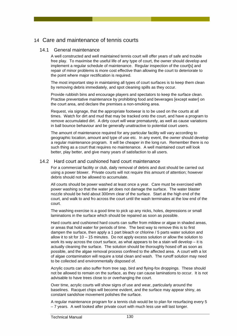
Technical Manual 130
14 Care and maintenance of tennis courts
14.1 General maintenance A well constructed and well maintained tennis court will offer years of safe and trouble free play. To maximise the useful life of any type of court, the owner should develop and implement a regular schedule of maintenance. Regular inspection of the court[s] and repair of minor problems is more cost effective than allowing the court to deteriorate to the point where major rectification is required.
The most important step in maintaining all types of court surfaces is to keep them clean by removing debris immediately, and spot cleaning spills as they occur.
Provide rubbish bins and encourage players and spectators to keep the surface clean. Practise preventative maintenance by prohibiting food and beverages [except water] on the court area, and declare the premises a non-smoking area.
Request, via signage, that the appropriate footwear is to be used on the courts at all times. Watch for dirt and mud that may be tracked onto the court, and have a program to remove accumulated dirt. A dirty court will wear prematurely, as well as cause variations in ball bounce behaviour and be generally unattractive to potential court users.
The amount of maintenance required for any particular facility will vary according to geographic location, amount and type of use etc. In any event, the owner should develop a regular maintenance program. It will be cheaper in the long run. Remember there is no such thing as a court that requires no maintenance. A well maintained court will look better, play better, and give many years of satisfaction to all users.
14.2 Hard court and cushioned hard court maintenance For a commercial facility or club, daily removal of debris and dust should be carried out using a power blower. Private courts will not require this amount of attention; however debris should not be allowed to accumulate.
All courts should be power washed at least once a year. Care must be exercised with power washing so that the water jet does not damage the surface. The water blaster nozzle should be held about 300mm clear of the surface. Start at the high end of the court, and walk to and fro across the court until the wash terminates at the low end of the court.
The washing exercise is a good time to pick up any nicks, holes, depressions or small laminations in the surface which should be repaired as soon as possible.
Hard courts and cushioned hard courts can suffer from mildew or algae in shaded areas, or areas that hold water for periods of time. The best way to remove this is to first dampen the surface, then apply a 1 part bleach or chlorine / 5 parts water solution and allow it to sit for 10 – 15 minutes. Do not apply excess solution or allow the solution to work its way across the court surface, as what appears to be a stain will develop – it is actually cleaning the surface. The solution should be thoroughly hosed off as soon as possible, and the algae removal process confined to the affected area. A court with a lot of algae contamination will require a total clean and wash. The runoff solution may need to be collected and environmentally disposed of.
Acrylic courts can also suffer from tree sap, bird and flying-fox droppings. These should not be allowed to remain on the surface, as they can cause laminations to occur. It is not advisable to have trees close to or overhanging the court.
Over time, acrylic courts will show signs of use and wear, particularly around the baselines. Racquet chips will become evident, and the surface may appear shiny, as constant sandshoe movement polishes the surface.
A regular maintenance program for a tennis club would be to plan for resurfacing every 5 – 7 years. A well looked after private court with much less use will last longer.
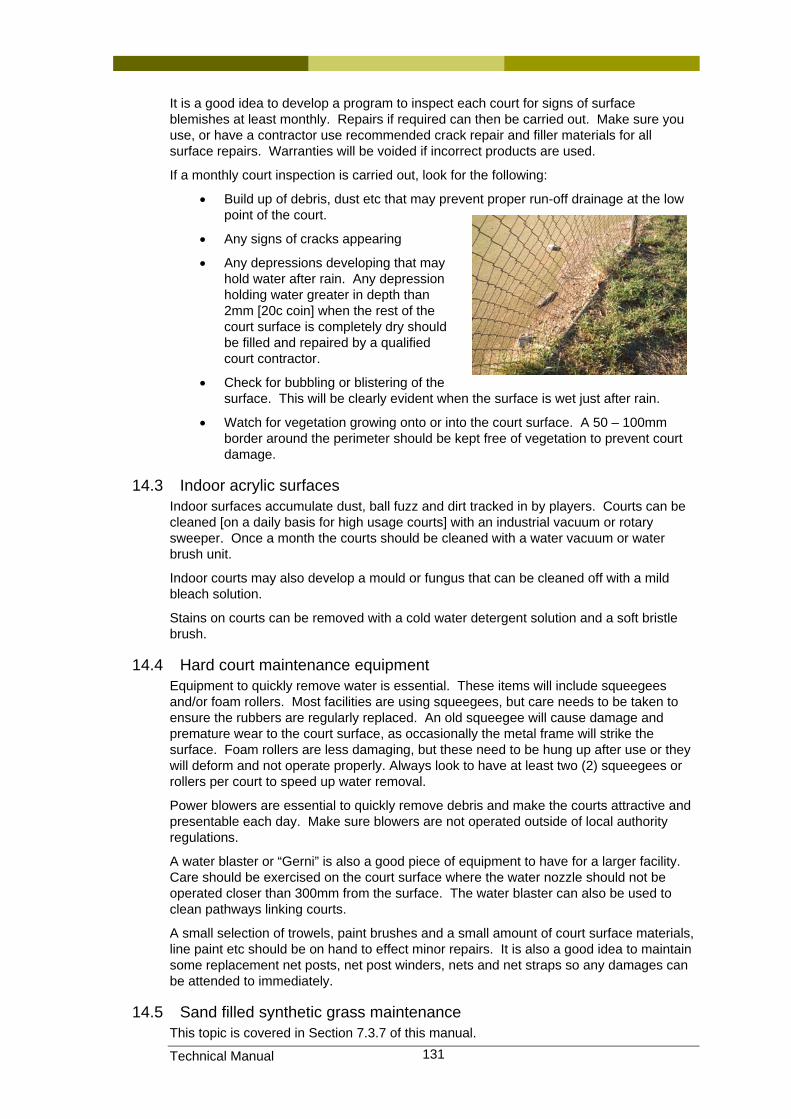
Technical Manual 131
It is a good idea to develop a program to inspect each court for signs of surface blemishes at least monthly. Repairs if required can then be carried out. Make sure you use, or have a contractor use recommended crack repair and filler materials for all surface repairs. Warranties will be voided if incorrect products are used.
If a monthly court inspection is carried out, look for the following:
• Build up of debris, dust etc that may prevent proper run-off drainage at the low point of the court.
• Any signs of cracks appearing
• Any depressions developing that may hold water after rain. Any depression holding water greater in depth than 2mm [20c coin] when the rest of the court surface is completely dry should be filled and repaired by a qualified court contractor.
• Check for bubbling or blistering of the surface. This will be clearly evident when the surface is wet just after rain.
• Watch for vegetation growing onto or into the court surface. A 50 – 100mm border around the perimeter should be kept free of vegetation to prevent court damage.
14.3 Indoor acrylic surfaces Indoor surfaces accumulate dust, ball fuzz and dirt tracked in by players. Courts can be cleaned [on a daily basis for high usage courts] with an industrial vacuum or rotary sweeper. Once a month the courts should be cleaned with a water vacuum or water brush unit.
Indoor courts may also develop a mould or fungus that can be cleaned off with a mild bleach solution.
Stains on courts can be removed with a cold water detergent solution and a soft bristle brush.
14.4 Hard court maintenance equipment Equipment to quickly remove water is essential. These items will include squeegees and/or foam rollers. Most facilities are using squeegees, but care needs to be taken to ensure the rubbers are regularly replaced. An old squeegee will cause damage and premature wear to the court surface, as occasionally the metal frame will strike the surface. Foam rollers are less damaging, but these need to be hung up after use or they will deform and not operate properly. Always look to have at least two (2) squeegees or rollers per court to speed up water removal.
Power blowers are essential to quickly remove debris and make the courts attractive and presentable each day. Make sure blowers are not operated outside of local authority regulations.
A water blaster or “Gerni” is also a good piece of equipment to have for a larger facility. Care should be exercised on the court surface where the water nozzle should not be operated closer than 300mm from the surface. The water blaster can also be used to clean pathways linking courts.
A small selection of trowels, paint brushes and a small amount of court surface materials, line paint etc should be on hand to effect minor repairs. It is also a good idea to maintain some replacement net posts, net post winders, nets and net straps so any damages can be attended to immediately.
14.5 Sand filled synthetic grass maintenance This topic is covered in Section 7.3.7 of this manual.
Technical Manual 132
Sand filled synthetic clay maintenance
This topic is covered in Section 7.4.4 of this manual.
14.6 Grass court maintenance This topic is covered in Section 7.5.10 of this manual.
Included in document by Peter Craven
14.7 Clay court maintenance This topic is covered in Section 7.6.6 of this manual
14.8 Court equipment maintenance
14.8.1 Installing a tennis net. Most nets have a 64mm – 76mm loop at both ends. When installing the net, one of these loops has to be removed to enable it to be wound onto the internal winding mechanism. Attach one loop to the anchor post, remove up to 400mm of vinyl coating on the cable at the other end, and then attach to the winder.
Turn the mechanism until the net is some 50mm above the required height [914mm] at the centre of the net. Do not over-tension the net cable, as it places a strain on the posts, and causes an exaggerated reaction when the ball strikes the net band. If wooden dowels are supplied with the net, then install them into the side bindings at each end.
Install the lacing cord by looping it through the grommets in the side bindings, and then through the lacing base on the net post. Pull the net close to the post, and continue the lacing down to the bottom of the post then tie it off.
Install the centre net strap and attach to the ground anchor. Adjust the height of the strap to the correct height [914mm]. If the net is not over tensioned, there is no need to wind the net down slightly overnight, as was the habit some years ago.
Nets come in varying heights ranging from 600mm [recommended for schools], to full drop, with the bottom band resting on the court surface. This can result in premature rotting of the stitches in the bottom band, and some debris accumulating on the bottom of the net. The full drop net is preferable for championship play, but most tennis facilities would be better served with a 760mm drop.
14.8.2 Net maintenance Repair tears as soon as possible. Cables and headbands can be replaced, however it usually results in the depth of the net being reduced by some 100mm. One headband replacement is usually satisfactory, but as the net wears and develops holes again, it is best to replace the net entirely.
14.8.3 Net post maintenance Never over-tension the net cable. In a tennis facility with several courts, it is usual for the winding handle to be removed so that staff are the people responsible for keeping the nets at the desired tension and height.
Keep posts clean and touch up nicks and scratches on coated posts to prevent rust. Use lubricating oil or gear lubricant on the winding mechanism. If a multi court facility, have a few extra sets of internal winding mechanisms in store for quick replacement.
Older lever type winding gear or protruding winding handles should be replaced as they present a player hazard.
Damaged or bent posts should be replaced. This is a simple matter if the post is sleeved, and the sleeve foundation is properly installed. If the post is fixed or foundations have moved, then the entire footing must be removed and replaced – not a simple job, as damage to the court surface around the post itself must be minimised.
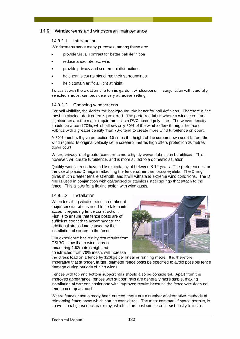
Technical Manual 133
14.9 Windscreens and windscreen maintenance
14.9.1.1 Introduction Windscreens serve many purposes, among these are:
• provide visual contrast for better ball definition
• reduce and/or deflect wind
• provide privacy and screen out distractions
• help tennis courts blend into their surroundings
• help contain artificial light at night.
To assist with the creation of a tennis garden, windscreens, in conjunction with carefully selected shrubs, can provide a very attractive setting.
14.9.1.2 Choosing windscreens For ball visibility, the darker the background, the better for ball definition. Therefore a fine mesh in black or dark green is preferred. The preferred fabric where a windscreen and sightscreen are the major requirements is a PVC coated polyester. The weave density should be around 70%, which allows only 30% of the wind to flow through the fabric. Fabrics with a greater density than 70% tend to create more wind turbulence on court.
A 70% mesh will give protection 10 times the height of the screen down court before the wind regains its original velocity i.e. a screen 2 metres high offers protection 20metres down court.
Where privacy is of greater concern, a more tightly woven fabric can be utilised. This, however, will create turbulence, and is more suited to a domestic situation.
Quality windscreens have a life expectancy of between 8-12 years. The preference is for the use of plated D rings in attaching the fence rather than brass eyelets. The D ring gives much greater tensile strength, and it will withstand extreme wind conditions. The D ring is used in conjunction with galvanised or stainless steel springs that attach to the fence. This allows for a flexing action with wind gusts.
14.9.1.3 Installation When installing windscreens, a number of major considerations need to be taken into account regarding fence construction. First is to ensure that fence posts are of sufficient strength to accommodate the additional stress load caused by the installation of screen to the fence.
Our experience backed by test results from CSIRO show that a wind screen measuring 1.83metres high and constructed from 70% mesh, will increase the stress load on a fence by 120kgs per lineal or running metre. It is therefore imperative that stronger, larger, diameter fence posts be specified to avoid possible fence damage during periods of high winds.
Fences with top and bottom support rails should also be considered. Apart from the improved appearance, fences with support rails are generally more stable, making installation of screens easier and with improved results because the fence wire does not tend to curl up as much.
Where fences have already been erected, there are a number of alternative methods of reinforcing fence posts which can be considered. The most common, if space permits, is conventional gooseneck backstay, which is the most simple and least costly to install.
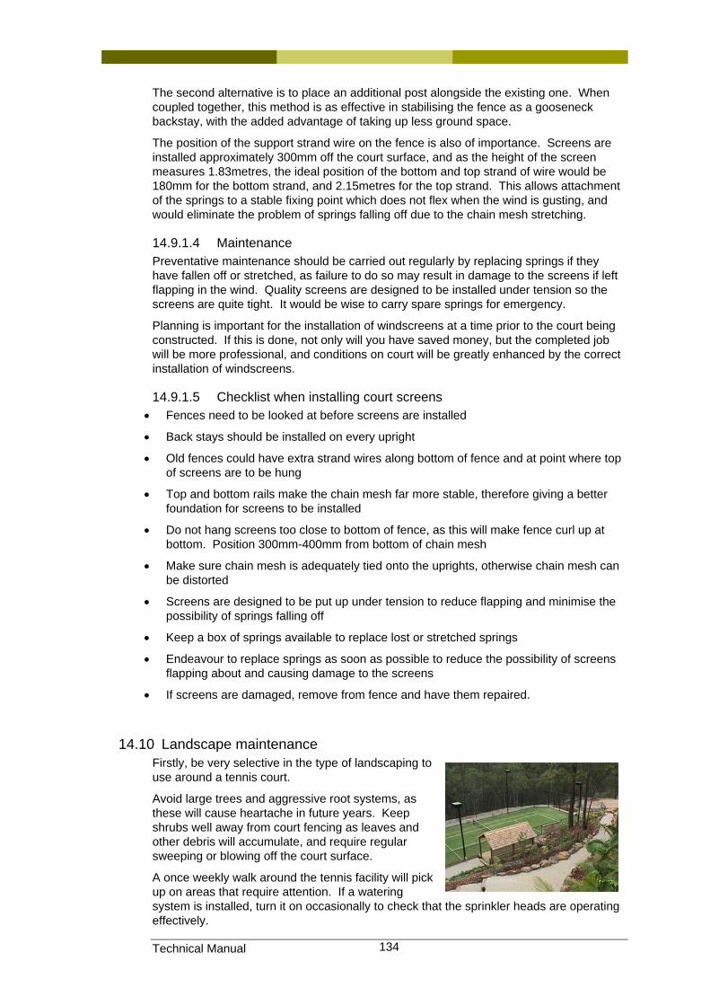
Technical Manual 134
The second alternative is to place an additional post alongside the existing one. When coupled together, this method is as effective in stabilising the fence as a gooseneck backstay, with the added advantage of taking up less ground space.
The position of the support strand wire on the fence is also of importance. Screens are installed approximately 300mm off the court surface, and as the height of the screen measures 1.83metres, the ideal position of the bottom and top strand of wire would be 180mm for the bottom strand, and 2.15metres for the top strand. This allows attachment of the springs to a stable fixing point which does not flex when the wind is gusting, and would eliminate the problem of springs falling off due to the chain mesh stretching.
14.9.1.4 Maintenance Preventative maintenance should be carried out regularly by replacing springs if they have fallen off or stretched, as failure to do so may result in damage to the screens if left flapping in the wind. Quality screens are designed to be installed under tension so the screens are quite tight. It would be wise to carry spare springs for emergency.
Planning is important for the installation of windscreens at a time prior to the court being constructed. If this is done, not only will you have saved money, but the completed job will be more professional, and conditions on court will be greatly enhanced by the correct installation of windscreens.
14.9.1.5 Checklist when installing court screens • Fences need to be looked at before screens are installed
• Back stays should be installed on every upright
• Old fences could have extra strand wires along bottom of fence and at point where top of screens are to be hung
• Top and bottom rails make the chain mesh far more stable, therefore giving a better foundation for screens to be installed
• Do not hang screens too close to bottom of fence, as this will make fence curl up at bottom. Position 300mm-400mm from bottom of chain mesh
• Make sure chain mesh is adequately tied onto the uprights, otherwise chain mesh can be distorted
• Screens are designed to be put up under tension to reduce flapping and minimise the possibility of springs falling off
• Keep a box of springs available to replace lost or stretched springs
• Endeavour to replace springs as soon as possible to reduce the possibility of screens flapping about and causing damage to the screens
• If screens are damaged, remove from fence and have them repaired.
14.10 Landscape maintenance Firstly, be very selective in the type of landscaping to use around a tennis court.
Avoid large trees and aggressive root systems, as these will cause heartache in future years. Keep shrubs well away from court fencing as leaves and other debris will accumulate, and require regular sweeping or blowing off the court surface.
A once weekly walk around the tennis facility will pick up on areas that require attention. If a watering system is installed, turn it on occasionally to check that the sprinkler heads are operating effectively.

Technical Manual 135
Choose shrubs and plants that require minimal amounts of water, but also ensure they are compatible with soil and climate conditions. Keep the landscaping tidy, and be prepared for some pruning, fertilising and replacement when the need arises. Have unobtrusive rubbish bins around the facility to deposit food and drink containers.
Technical Manual 136
15 Document control
15.1 Date of preparation The collation of information took place over many months prior to the release of this draft version of this manual. This initial draft was placed on Tennis Queensland’s web site for comment and feedback in December 2006 and as such this document will be continuously updated in the following months until Tennis Queensland is satisfied that the document is suitable for official release.
15.2 Review date. Whilst this document remains in a draft format, it will essentially be a live document that will be updated at least monthly, or more frequently if required. Once it has been officially released, it is anticipated than an annual review and updated version would be produced and issued. If the changes in any one year are considered very minor, a small supplement or update could be issued summarising these changes which could then be inserted into the current document rather than re-issuing or reprinting the whole manual.
15.3 Disclaimers As stated in the Introduction (Section 1) of this manual, the information contained herein should not replace the advice that should be sought and provided by professionals such as engineers, architects and registered court builders. This manual has been primarily produced to provide members of the tennis community with assistance to understand the concepts and technical aspects of tennis court construction and maintenance.

Technical Manual 137
16 APPENDICES Glossary of terms
ITF International Tennis Federation. This is the governing body of the sport and establishes rules for the game and the facilities.
TA Tennis Australia – administrator of the sport nationally.
TQ Tennis Queensland – administrator of the sport in Queensland.
Banked Courts multiple courts on a single platform. Often banked courts share a surrounding fence and are separated from each other with low height or no dividing fences. The practice of omitting dividing fences is not encouraged due to the risk of injury to players from stray balls and the consequential litigation issues.
Links to other sources of information have been provided throughout the body of this document where applicable and relevant, rather than as a summary in this Section of the manual.
The following pages include:
• Current “Plexipave” and “Plexicushion” brochures
• A current Rebound Ace Colour Selection Chart for information as referenced in the body of this document.