Technical Manual - Lowe's
12
This manual should remain with the unit. Technical Manual DLM Module
Transcript of Technical Manual - Lowe's
This manual should remain with the unit.
Technical ManualDLM Module
The manufacturer cannot anticipate every possible circumstance that might involve a hazard. The warnings in this manual, and on tags and decals affixed to the unit are, therefore, not all-inclusive. If using a procedure, work method or operating technique the manu-facturer does not specifically recommend, ensure that it is safe for others. Also make sure the procedure, work method or operating technique chosen does not render the transfer switch unsafe.
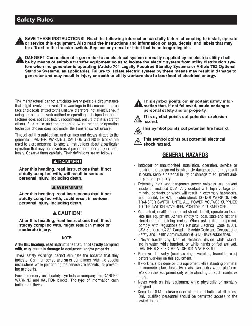
Throughout this publication, and on tags and decals affixed to the generator, DANGER, WARNING, CAUTION and NOTE blocks are used to alert personnel to special instructions about a particular operation that may be hazardous if performed incorrectly or care-lessly. Observe them carefully. Their definitions are as follows:
After this heading, read instructions that, if not strictly complied with, will result in serious personal injury, including death.
After this heading, read instructions that, if not strictly complied with, could result in serious personal injury, including death.
After this heading, read instructions that, if not strictly complied with, might result in minor or moderate injury.
NOTE:
After this heading, read instructions that, if not strictly complied with, may result in damage to equipment and/or property.
These safety warnings cannot eliminate the hazards that they indicate. Common sense and strict compliance with the special instructions while performing the service are essential to prevent-ing accidents.
Four commonly used safety symbols accompany the DANGER, WARNING and CAUTION blocks. The type of information each indicates follows:
This symbol points out important safety infor-mation that, if not followed, could endanger personal safety and/or property.
This symbol points out potential explosion hazard.
This symbol points out potential fire hazard.
This symbol points out potential electrical shock hazard.
GENERAL HAZARDS
Improper or unauthorized installation, operation, service or • repair of the equipment is extremely dangerous and may result in death, serious personal injury, or damage to equipment and/or personal property.Extremely high and dangerous power voltages are present • inside an installed DLM. Any contact with high voltage ter-minals, contacts or wires will result in extremely hazardous, and possibly LETHAL, electric shock. DO NOT WORK ON THE TRANSFER SWITCH UNTIL ALL POWER VOLTAGE SUPPLIES TO THE SWITCH HAVE BEEN POSITIVELY TURNED OFF.Competent, qualified personnel should install, operate and ser-• vice this equipment. Adhere strictly to local, state and national electrical and building codes. When using this equipment, comply with regulations the National Electrical Code (NEC), CSA Standard; C22.1 Canadian Electric Code and Occupational Safety and Health Administration (OSHA) have established. Never handle any kind of electrical device while stand-• ing in water, while barefoot, or while hands or feet are wet. DANGEROUS ELECTRICAL SHOCK MAY RESULT.Remove all jewelry (such as rings, watches, bracelets, etc.) • before working on this equipment.If work must be done on this equipment while standing on metal • or concrete, place insulative mats over a dry wood platform. Work on this equipment only while standing on such insulative mats.Never work on this equipment while physically or mentally • fatigued.Keep the DLM enclosure door closed and bolted at all times. • Only qualified personnel should be permitted access to the switch interior.
SAVE THESE INSTRUCTIONS! Read the following information carefully before attempting to install, operate or service this equipment. Also read the instructions and information on tags, decals, and labels that may be affixed to the transfer switch. Replace any decal or label that is no longer legible.
DANGER! Connection of a generator to an electrical system normally supplied by an electric utility shall be by means of suitable transfer equipment so as to isolate the electric system from utility distribution sys-tem when the generator is operating (Article 701 Legally Required Standby Systems or Article 702 Optional Standby Systems, as applicable). Failure to isolate electric system by these means may result in damage to generator and may result in injury or death to utility workers due to backfeed of electrical energy.
Safety Rules
1
In case of an accident caused by electric shock, immediately • shut down the source of electrical power. If this is not possible, attempt to free the victim from the live conductor but AVOID DIRECT CONTACT WITH THE VICTIM. Use a nonconducting implement, such as a dry rope or board, to free the victim from the live conductor. If the victim is unconscious, apply first aid and get immediate medical help.
Safety Rules ................................................. Inside Front Cover
General Information ................................................................. 21.1 Introduction ................................................................................ 21.2 Unpacking .................................................................................. 21.3 Equipment Description ................................................................ 21.4 Transfer Switch Data Decal ......................................................... 21.5 Safe Use of DLM ........................................................................ 2
Installation ............................................................................... 32.1 Introduction to Installation ........................................................... 32.2 Mounting .................................................................................... 32.3 Connecting Power Source and Load Lines .................................. 3 2.3.1 2-pole Mechanism ............................................................ 32.4 Connecting Control Wires ........................................................... 4
Operation ................................................................................. 43.1 Functional Tests & Adjustments .................................................. 4
Exploded Views & Parts Lists .................................................. 6
Notes ....................................................................................... 8
For authorized service, reference the dealer locator
number found inside thegenerator owner’s manual.
Table of Contents
2
1.1 INTRODUCTIONThis manual has been prepared especially for the purpose of famil-iarizing personnel with the design, application, installation, opera-tion and servicing of the applicable equipment. Read the manual carefully and comply with all instructions. This will help to prevent accidents or damage to equipment that might otherwise be caused by carelessness, incorrect application, or improper procedures.
Every effort has been expended to make sure that the contents of this manual are both accurate and current. The manufacturer, however, reserves the right to change, alter or otherwise improve the product at any time without prior notice.
1.2 UNPACKINGCarefully unpack the module. Inspect closely for any damage that might have occurred during shipment. The purchaser must file with the carrier any claims for loss or damage incurred while in transit.
1.3 EQUIPMENT DESCRIPTIONThis Digital Load Module (DLM) is used to control or turn on and off a load under the control of the Load Shed Module (LSM) in the transfer switch.
The DLM consists of a 2-pole N.O. relay mounted in an enclosure. The 2-pole relay is rated to control:
Current – 55 resistive or 40A inductive.• Voltage – 600 Vac.• Motor Rating – 3 hp @ 240 Vac.• LRA – 240 Amps @ 240 Vac.• Coil Voltage – 120 Vac (0.06A holding current)•
The enclosure is non-metallic and is rated UL type 3R.
A UL type 3R enclosure primarily provides a degree of protection against falling rain and sleet; is undamaged by the formation of ice on the enclosure. It is suitable for mounting indoors or outdoors.
The DLM module is UL listed as industrial control equipment, to U.S. and Canadian safety standards.
Several crimp-on connectors are supplied for use in making the contactor coil connections (1/4” quick connect) and grounding terminal connections (1/4” ring terminals). Note: Use yellow colored insulator terminals for #10-#12 AWG wire, blue colored insulator terminals for #14-16 AWG wire.
1.4 TRANSFER SWITCH DATA DECAL
A DATA DECAL is permanently affixed to the DLM enclosure. Use this DLM only within the specific limits shown on the DATA DECAL and on other decals and labels that may be affixed. This will pre-vent damage to equipment and property.
When requesting information or ordering parts for this equipment, make sure to include all information from the DATA DECAL.
Record the Model number in the space provided below for future reference.
MODEL #
1.5 SAFE USE OF DLMBefore installing, operating or servicing this equipment, read the SAFETY RULES (inside front cover) carefully. Comply strictly with all SAFETY RULES to prevent accidents and/or damage to the equipment. Also, be sure to read all instructions and information found on tags, labels and decals affixed to the equipment.
A publication that outlines the safe use of DLM is:
NFPA 70; National Electrical Code• NOTE:
It is essential to use the latest version of any standard to ensure correct and current information.
General Information
3
2.1 INTRODUCTION TO INSTALLATION
Installing the DLM includes the following procedures:
Mounting the enclosure.• Connecting line and load power leads.• Connecting relay control leads.•
2.2 MOUNTING
Handle DLM carefully when installing. Do not drop the DLM. Protect the DLM against impact at all times, and against construction grit and metal chips. Never install a DLM that has been damaged.
Install the DLM as close as possible to the electrical loads that are to be connected to it. The DLM enclosure must be mounted on the back surface of the enclosure.
Indoor installation• – The enclosure can be mounted in any orientation that is convenient.Outdoor installation• – The enclosure must be mounted with the drain hole on the bottom.
To prevent switch distortion, level all mounting points. To maintain the type 3R rating a suitable UL listed box connector must be used. The connector must be UL listed for use in “wet locations”.
Remove screws (2) holding the cover in place.
Mounting slots and holes (4 – 5mm) are provided in the back of the enclosure. The plastic covering will need to be removed from the hole before use of the holes and/ or slots. This can be done with the mounting screw or a screwdriver. Only remove plastic covering from holes that will be used. See Figure 2.1.
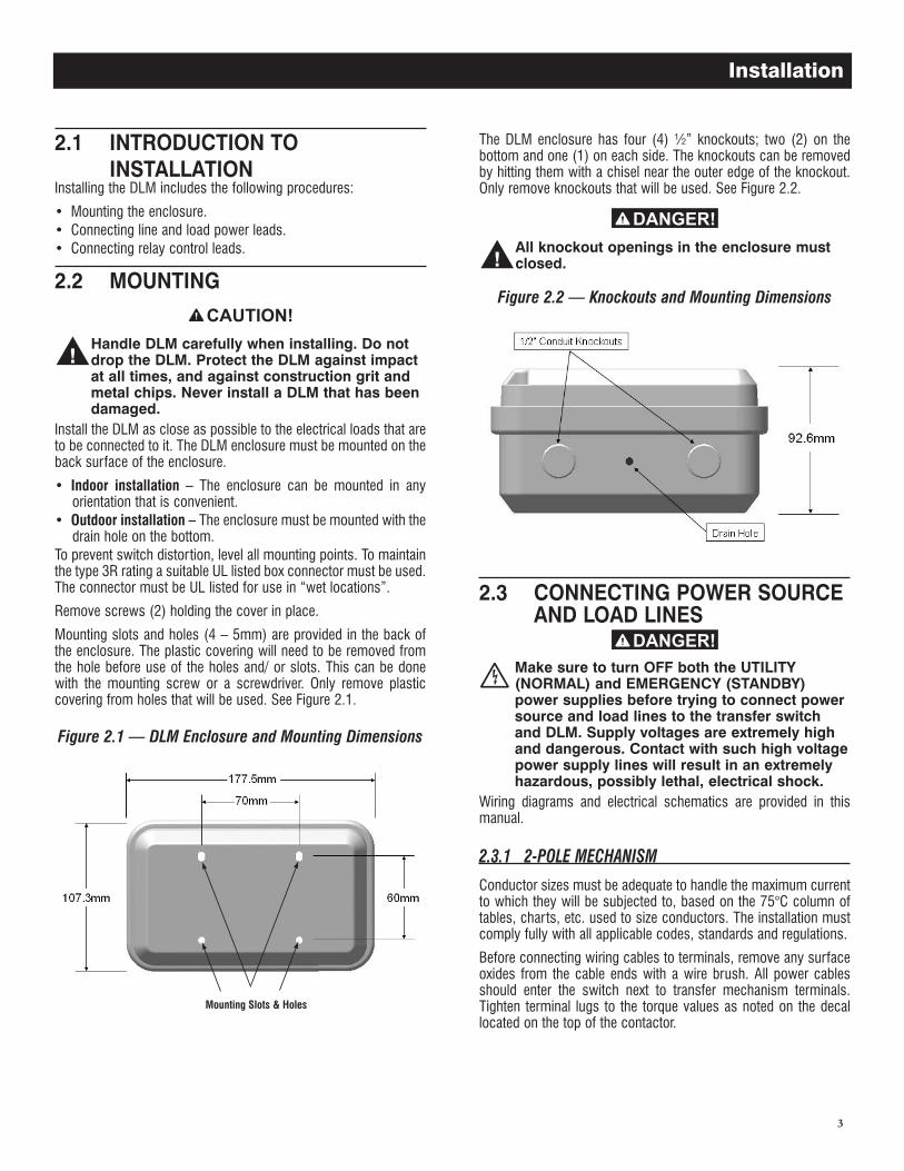
Figure 2.1 — DLM Enclosure and Mounting Dimensions
Mounting Slots & Holes
The DLM enclosure has four (4) ½” knockouts; two (2) on the bottom and one (1) on each side. The knockouts can be removed by hitting them with a chisel near the outer edge of the knockout. Only remove knockouts that will be used. See Figure 2.2.
All knockout openings in the enclosure must closed.
Figure 2.2 — Knockouts and Mounting Dimensions
2.3 CONNECTING POWER SOURCE AND LOAD LINES
Make sure to turn OFF both the UTILITY (NORMAL) and EMERGENCY (STANDBY) power supplies before trying to connect power source and load lines to the transfer switch and DLM. Supply voltages are extremely high and dangerous. Contact with such high voltage power supply lines will result in an extremely hazardous, possibly lethal, electrical shock.
Wiring diagrams and electrical schematics are provided in this manual.
2.3.1 2-POLE MECHANISM
Conductor sizes must be adequate to handle the maximum current to which they will be subjected to, based on the 75°C column of tables, charts, etc. used to size conductors. The installation must comply fully with all applicable codes, standards and regulations.
Before connecting wiring cables to terminals, remove any surface oxides from the cable ends with a wire brush. All power cables should enter the switch next to transfer mechanism terminals. Tighten terminal lugs to the torque values as noted on the decal located on the top of the contactor.
Installation
4
Use a torque wrench to tighten the conductors, being sure not to over tighten, or damage to the switch base could occur. If not tightened enough, a loose connection would result, caus-ing excess heat which could damage the switch base.
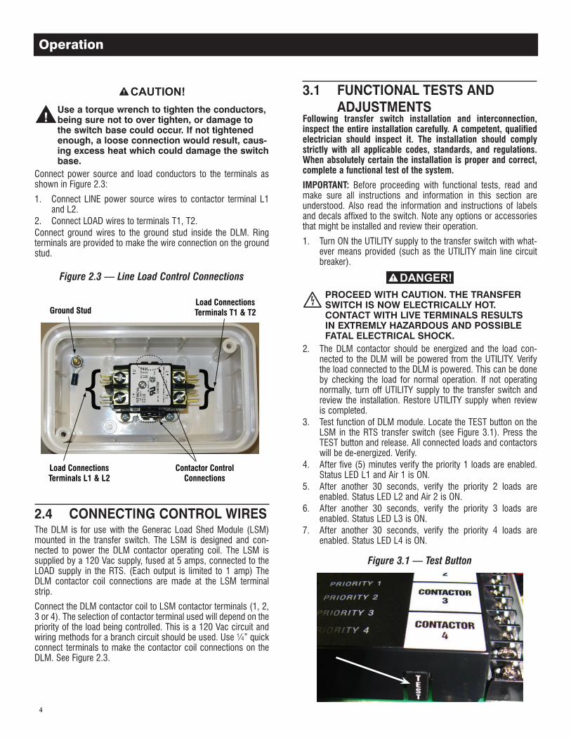
Connect power source and load conductors to the terminals as shown in Figure 2.3:
1. Connect LINE power source wires to contactor terminal L1 and L2.
2. Connect LOAD wires to terminals T1, T2.Connect ground wires to the ground stud inside the DLM. Ring terminals are provided to make the wire connection on the ground stud.
Figure 2.3 — Line Load Control Connections
Ground Stud
Contactor ControlConnections
Load ConnectionsTerminals T1 & T2
Load ConnectionsTerminals L1 & L2
}}
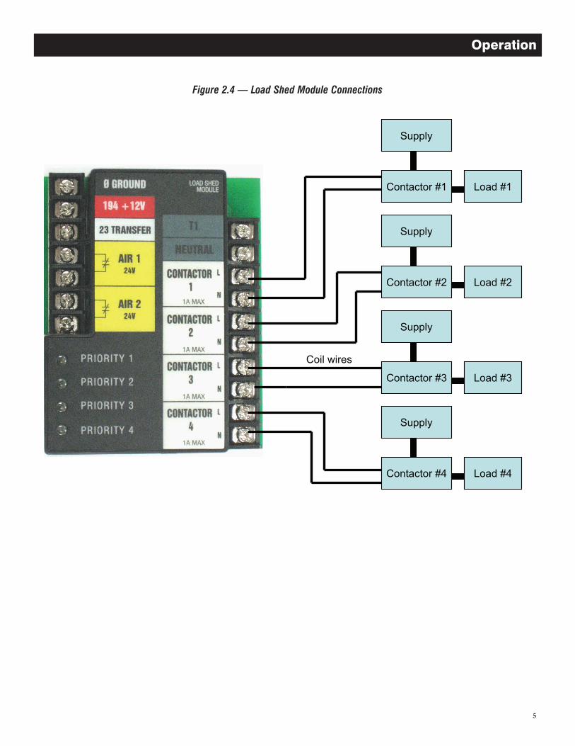
2.4 CONNECTING CONTROL WIRESThe DLM is for use with the Generac Load Shed Module (LSM) mounted in the transfer switch. The LSM is designed and con-nected to power the DLM contactor operating coil. The LSM is supplied by a 120 Vac supply, fused at 5 amps, connected to the LOAD supply in the RTS. (Each output is limited to 1 amp) The DLM contactor coil connections are made at the LSM terminal strip.
Connect the DLM contactor coil to LSM contactor terminals (1, 2, 3 or 4). The selection of contactor terminal used will depend on the priority of the load being controlled. This is a 120 Vac circuit and wiring methods for a branch circuit should be used. Use ¼” quick connect terminals to make the contactor coil connections on the DLM. See Figure 2.3.
3.1 FUNCTIONAL TESTS ANDADJUSTMENTS
Following transfer switch installation and interconnection, inspect the entire installation carefully. A competent, qualified electrician should inspect it. The installation should comply strictly with all applicable codes, standards, and regulations. When absolutely certain the installation is proper and correct, complete a functional test of the system.
IMPORTANT: Before proceeding with functional tests, read and make sure all instructions and information in this section are understood. Also read the information and instructions of labels and decals affixed to the switch. Note any options or accessories that might be installed and review their operation.
1. Turn ON the UTILITY supply to the transfer switch with what-ever means provided (such as the UTILITY main line circuit breaker).
PROCEED WITH CAUTION. THE TRANSFER SWITCH IS NOW ELECTRICALLY HOT. CONTACT WITH LIVE TERMINALS RESULTS IN EXTREMLY HAZARDOUS AND POSSIBLE FATAL ELECTRICAL SHOCK.
2. The DLM contactor should be energized and the load con-nected to the DLM will be powered from the UTILITY. Verify the load connected to the DLM is powered. This can be done by checking the load for normal operation. If not operating normally, turn off UTILITY supply to the transfer switch and review the installation. Restore UTILITY supply when review is completed.
3. Test function of DLM module. Locate the TEST button on the LSM in the RTS transfer switch (see Figure 3.1). Press the TEST button and release. All connected loads and contactors will be de-energized. Verify.
4. After five (5) minutes verify the priority 1 loads are enabled. Status LED L1 and Air 1 is ON.
5. After another 30 seconds, verify the priority 2 loads are enabled. Status LED L2 and Air 2 is ON.
6. After another 30 seconds, verify the priority 3 loads are enabled. Status LED L3 is ON.
7. After another 30 seconds, verify the priority 4 loads are enabled. Status LED L4 is ON.
Figure 3.1 — Test Button
Operation
5
Contactor #1 Load #1
Supply
Coil wires
Contactor #2 Load #2
Supply
Contactor #4 Load #4
Supply
Contactor #3 Load #3
Supply
Figure 2.4 — Load Shed Module Connections
Operation
6
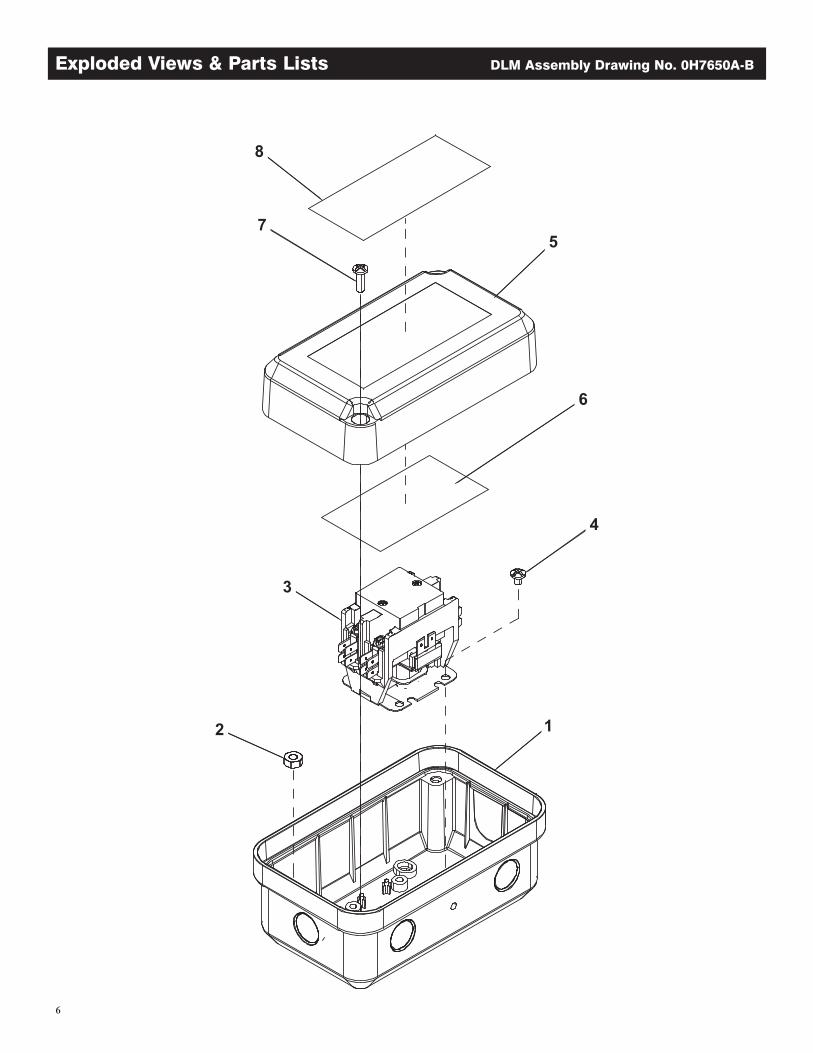
Exploded Views & Parts Lists DLM Assembly Drawing No. 0H7650A-B
7
Parts List on page 18.
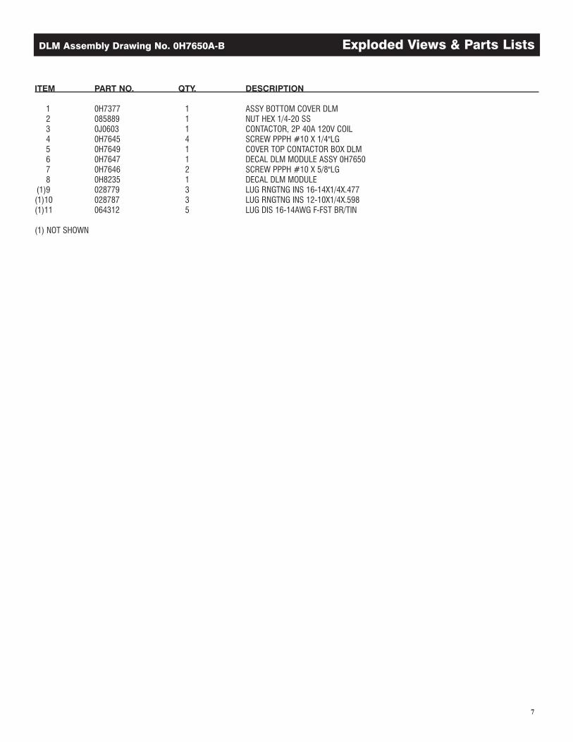
DLM Assembly Drawing No. 0H7650A-B Exploded Views & Parts Lists
ITEM PART NO. QTY. DESCRIPTION
1 0H7377 1 ASSY BOTTOM COVER DLM 2 085889 1 NUT HEX 1/4-20 SS 3 0J0603 1 CONTACTOR, 2P 40A 120V COIL 4 0H7645 4 SCREW PPPH #10 X 1/4"LG 5 0H7649 1 COVER TOP CONTACTOR BOX DLM 6 0H7647 1 DECAL DLM MODULE ASSY 0H7650 7 0H7646 2 SCREW PPPH #10 X 5/8"LG 8 0H8235 1 DECAL DLM MODULE (1)9 028779 3 LUG RNGTNG INS 16-14X1/4X.477 (1)10 028787 3 LUG RNGTNG INS 12-10X1/4X.598 (1)11 064312 5 LUG DIS 16-14AWG F-FST BR/TIN
(1) NOT SHOWN

8
Notes

9
Notes

Part No. 0H9161 Revision B (10/29/10) Printed in U.S.A.