Technical - Mabey · We recommend that you contact Mabey Hire engineers for guidance. ... local...
14
TECHNICAL DATA SHEET Mass 10 Document Ref: TDSM10 Page No. 1 of 14 THE INFORMATION ON THIS DATA SHEET REMAINS THE PROPERTY OF MABEY HIRE LTD. AND IS NOT TO BE REPRODUCED WITHOUT WRITTEN PERMISSION. WE RESERVE THE RIGHT TO AMEND THIS DATA AT ANY TIME WITHOUT PRIOR NOTICE AND YOU SHOULD THEREFORE CHECK OUR WEBSITE TO ESTABLISH ITS VALIDITY . Issue No: 01 Further Information Tel: +44 (0) 1942 725 343 Issue Date: June 2016 www.mabeyhire.co.uk [email protected] Technical Data Sheet Mabey Hire Ltd. Structural Support & Bridging Bridge House, Strange Road, Garswood, Lancashire WN4 0RX United Kingdom Telephone: +44 (0) 1942 725 343 Facsimile: +44 (0) 1942 270 893 Email: [email protected] Website: www.mabeyhire.co.uk Mass 10 Mass 25 Mass 50 MAT 125 Superprop Hydraulics Quickbridge MU Falsework MU Bridging Compact Bridging BarrierGuard 800 Instrumentation Eurocode Compliant
Transcript of Technical - Mabey · We recommend that you contact Mabey Hire engineers for guidance. ... local...

T E C H N I C A L D A T A S H E E T
Mass 10
Document Ref: TDSM10 Page No. 1 of 14 THE INFORMATION ON THIS DATA SHEET REMAINS THE PROPERTY OF MABEY HIRE
LTD. AND IS NOT TO BE REPRODUCED WITHOUT WRITTEN PERMISSION. WE RESERVE THE RIGHT TO AMEND THIS DATA AT ANY TIME WITHOUT PRIOR
NOTICE AND YOU SHOULD THEREFORE CHECK OUR WEBSITE TO ESTABLISH ITS VALIDITY.
Issue No: 01 Further Information Tel: +44 (0) 1942 725 343
Issue Date: June 2016
www. mabeyh i r e . co .uk ac t i on@mabeyh i r e . co . uk
Technical
Data
Sheet
Mabey Hire Ltd. Structural Support & Bridging Bridge House, Strange Road, Garswood, Lancashire WN4 0RX United Kingdom Telephone: +44 (0) 1942 725 343 Facsimile: +44 (0) 1942 270 893 Email: [email protected] Website: www.mabeyhire.co.uk
Mass 10 Mass 25 Mass 50 MAT 125
Superprop Hydraulics
Quickbridge MU Falsework
MU Bridging Compact Bridging BarrierGuard 800
Instrumentation
Eurocode Compliant

T E C H N I C A L D A T A S H E E T
Mass 10
Document Ref: TDSM10 Page No. 2 of 14 THE INFORMATION ON THIS DATA SHEET REMAINS THE PROPERTY OF MABEY HIRE
LTD. AND IS NOT TO BE REPRODUCED WITHOUT WRITTEN PERMISSION. WE RESERVE THE RIGHT TO AMEND THIS DATA AT ANY TIME WITHOUT PRIOR
NOTICE AND YOU SHOULD THEREFORE CHECK OUR WEBSITE TO ESTABLISH ITS VALIDITY .
Issue No: 01 Further Information Tel: +44 (0) 1942 725 343 Issue Date: June 2016
www. mabeyh i r e . co .uk ac t i on@mabeyh i r e . co . uk
Index
Reference Description Page No.
Contents
1.0 Introduction 3 2.0 Section Properties, Capacities & Weights 5
2.1 Prop Units 5 2.2 Adjustable Ends & Accessories 9 2.3 Shutter Beams 11 2.4 Plumbing Prop 11 2.5 Needle Beams & Accessories 12
3.0 Equipment List & Bolt Application Table 14
Contents
T E C H N I C A L D A T A S H E E T
Mass 10
Document Ref: TDSM10 Page No. 3 of 14 THE INFORMATION ON THIS DATA SHEET REMAINS THE PROPERTY OF MABEY HIRE
LTD. AND IS NOT TO BE REPRODUCED WITHOUT WRITTEN PERMISSION. WE RESERVE THE RIGHT TO AMEND THIS DATA AT ANY TIME WITHOUT PRIOR
NOTICE AND YOU SHOULD THEREFORE CHECK OUR WEBSITE TO ESTABLISH ITS VALIDITY .
Issue No: 01 Further Information Tel: +44 (0) 1942 725 343 Issue Date: June 2016
www. mabeyh i r e . co .uk ac t i on@mabeyh i r e . co . uk
Application
This Technical Data Sheet is designed to provide information of sufficient content and detail as to enable engineers, competent in structural analysis and structural steelwork design, to safely design structures incorporating Mass 10. Design Standards
The resistance values given in this data sheet have been calculated in accordance with the latest revisions of the following Eurocode Standards:
BS EN 1993-1-1:2005 incl. corrigenda Feb 2006 and April 2009
BS EN 1993-1-3:2006 incl. corrigendum Nov 2009
BS EN 1993-1-5:2006 incl. corrigendum April 2009
BS EN 1993-1-8:2005 incl. corrigenda Dec 2005, Sept 2006, July 2009 and Aug 2010 Design Philosophy
The British Standard method of permissible stress design has been replaced by the Eurocode limit state design method, which utilises a partial factor method. The principles of the Eurocode design method are outlined below. The design value of an action effect shall not exceed the corresponding design resistance of the element:
Where:
Fd = ƔF x Fk
Rd = Rk / ƔM
Fd is the design value of an action (be that a force,
moment, or shear etc.)
Rd is the design value of the resistance (be that a force,
moment, or shear etc.)
Fk is the characteristic value of an action (such as dead
load, live load etc.)
Rk is the characteristic value of the resistance (e.g. axial
capacity)
ƔF is the partial factor for actions ƔM is the partial factor for a material property
This data sheet gives Safe Working Capacities by assuming a ƔF value of 1.50.
ƔM is used in accordance with the Eurocodes.
Please refer to further details on the following page.
Fd ≤ Rd
1.0 Introduction

T E C H N I C A L D A T A S H E E T
Mass 10
Document Ref: TDSM10 Page No. 4 of 14 THE INFORMATION ON THIS DATA SHEET REMAINS THE PROPERTY OF MABEY HIRE
LTD. AND IS NOT TO BE REPRODUCED WITHOUT WRITTEN PERMISSION. WE RESERVE THE RIGHT TO AMEND THIS DATA AT ANY TIME WITHOUT PRIOR
NOTICE AND YOU SHOULD THEREFORE CHECK OUR WEBSITE TO ESTABLISH ITS VALIDITY .
Issue No: 01 Further Information Tel: +44 (0) 1942 725 343 Issue Date: June 2016
www. mabeyh i r e . co .uk ac t i on@mabeyh i r e . co . uk
How this Eurocode Data has been Established
This data sheet gives Safe Working Capacities that may be compared to actual loads/effects. Mabey Hire have chosen not to publish “Design Resistance” values because they could lead to errors and unsafe designs due to:-
Values being mistaken for SWL values (major risk)
The risk of low Partial Factors being used in certain circumstances resulting in overall Factor of Safety (FOS) values of < 1.40, inappropriate for Temporary Works
The “Characteristic Resistances” of all the products have been assessed in detail in accordance with the Eurocodes. Where the values have been influenced by the results of testing, the use of the test data has also been carried out in accordance with the requirements of the Eurocodes. Diagram Illustrating Factors
Safe working capacities in this data sheet are the lesser of these two values.
How to Use the Technical Data Sheet
a) Use SWL values straight from the data sheet. In cases where the Eurocodes specify ƔF > 1.50 (e.g. certain rail and
wind actions) then method (b) below should be adopted. Or
b) Providing that Actions (Loads) have been multiplied by ƔF (Load Factors) to produce “Design Load Effects”, then
tabulated values may be multiplied by 1.50 to give minimum “Design Resistances” and compared to the Design Load
Effect. Minimum FOS
When using method (b), Mabey Hire imposes a minimum ƔF x ƔM of 1.60.
This is to eliminate lower FOS values that would be inappropriate for Temporary Works. We recommend that you contact Mabey Hire engineers for guidance.
1.0 Introduction
Rk
ƔM x (ƔF = 1.50)
Mabey Strength
Min FoS = 2.0
T E C H N I C A L D A T A S H E E T
Mass 10
Document Ref: TDSM10 Page No. 5 of 14 THE INFORMATION ON THIS DATA SHEET REMAINS THE PROPERTY OF MABEY HIRE
LTD. AND IS NOT TO BE REPRODUCED WITHOUT WRITTEN PERMISSION. WE RESERVE THE RIGHT TO AMEND THIS DATA AT ANY TIME WITHOUT PRIOR
NOTICE AND YOU SHOULD THEREFORE CHECK OUR WEBSITE TO ESTABLISH ITS VALIDITY .
Issue No: 01 Further Information Tel: +44 (0) 1942 725 343 Issue Date: June 2016
www. mabeyh i r e . co .uk ac t i on@mabeyh i r e . co . uk
2.1 Prop Units
2.1.1 Details
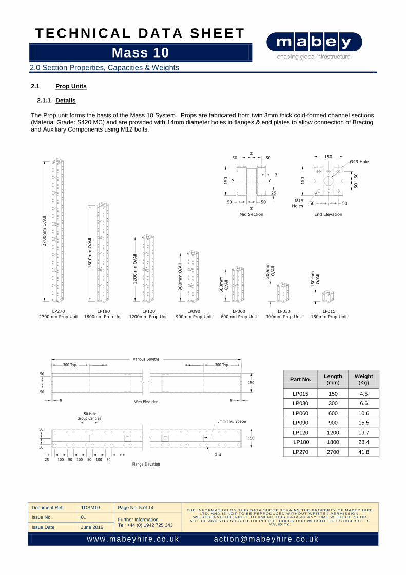
The Prop unit forms the basis of the Mass 10 System. Props are fabricated from twin 3mm thick cold-formed channel sections (Material Grade: S420 MC) and are provided with 14mm diameter holes in flanges & end plates to allow connection of Bracing and Auxiliary Components using M12 bolts.
Part No. Length (mm)
Weight (Kg)
LP015 150 4.5
LP030 300 6.6
LP060 600 10.6
LP090 900 15.5
LP120 1200 19.7
LP180 1800 28.4
LP270 2700 41.8
2.0 Section Properties, Capacities & Weights

T E C H N I C A L D A T A S H E E T
Mass 10
Document Ref: TDSM10 Page No. 6 of 14 THE INFORMATION ON THIS DATA SHEET REMAINS THE PROPERTY OF MABEY HIRE
LTD. AND IS NOT TO BE REPRODUCED WITHOUT WRITTEN PERMISSION. WE RESERVE THE RIGHT TO AMEND THIS DATA AT ANY TIME WITHOUT PRIOR
NOTICE AND YOU SHOULD THEREFORE CHECK OUR WEBSITE TO ESTABLISH ITS VALIDITY .
Issue No: 01 Further Information Tel: +44 (0) 1942 725 343 Issue Date: June 2016
www. mabeyh i r e . co .uk ac t i on@mabeyh i r e . co . uk
2.1.2 Section Properties
2.1.3 Weighted Average for Deflection Calculations
2.1.4 Resistance - Axial
Refer to Chart A for compressive resistance for a given effective length of the member. The values below are based on a 2m effective length.
2.1.5 Prop Resistance – End Details
Application of the load at the ends of the Props should be through a standard Mass 10 part such as an Adjustable End fitting or Baseplate. In the absence of this, care must be taken to ensure that the load is applied uniformly over the Prop End Plate. Otherwise the resistance may be limited by the local resistance of the End Plate & Channels.
2.1.6 Loading Resistance – Bending and Shear
Refer to Chart B for the bending resistance for a given effective length of member. The values below are based on a 2m effective length.
Area (cm2) Inertia (cm
4) Section Modulus (cm
3) Radius of Gyration (cm)
A Iy Iz Wel,y Wel,z iy iz
Nett 15.0 450 306 60 41 5.4 4.5
Gross 16.7 541 348 72 46 5.6 4.5
Area (cm2) Inertia (cm
4)
A Iy Iz
Weighted Average 16.4 524 340
Compression Resistance Tension Resistance
Axial Load
No Eccentricity Eccentricity 20mm y-y
Eccentricity 20mm z-z
Using 4No. Bolts (Gr. 8.8)
Using 6No. Bolts (Gr. 8.8)
Axial Compression
Resistance (kN) 200 110 100 80 120
Full
Section Bolted Joint
(4No. Bolts Gr. 8.8) Bolted Joint
(6No. Bolts Gr. 8.8)
Bending Major Axis (y-y) kNm 13.0 5.0 7.5
Bending Minor Axis (z-z) kNm 6.4 5.0 5.0
Shear Major Axis (y-y) kN 110 70 105
Shear Minor Axis (z-z) kN 50 50 * 50 *
Note on Combined Effects Where appropriate the combined effects of axial load, bending & local effects must be considered. Please refer to Mabey Hire Engineers where advice is required.
The weighted average value is for use in analysis computer software to accurately model member axial & lateral deflection e.g. in computer frame analysis.
* Limited by section properties
2.0 Section Properties, Capacities & Weights

T E C H N I C A L D A T A S H E E T
Mass 10
Document Ref: TDSM10 Page No. 7 of 14 THE INFORMATION ON THIS DATA SHEET REMAINS THE PROPERTY OF MABEY HIRE
LTD. AND IS NOT TO BE REPRODUCED WITHOUT WRITTEN PERMISSION. WE RESERVE THE RIGHT TO AMEND THIS DATA AT ANY TIME WITHOUT PRIOR
NOTICE AND YOU SHOULD THEREFORE CHECK OUR WEBSITE TO ESTABLISH ITS VALIDITY .
Issue No: 01 Further Information Tel: +44 (0) 1942 725 343 Issue Date: June 2016
www. mabeyh i r e . co .uk ac t i on@mabeyh i r e . co . uk
2.1.8 Load Resistance – Axial & Bending
2.0 Section Properties, Capacities & Weights
NB 1: Capacity may be increased for short Prop lengths, refer to Mabey Hire Engineers for details. Load should be applied through a stiff end unit. If applied via a local offset inducing concentrated loading then consideration should be given to local failure, see Note 2.1.5. NB 2: For horizontal prop applications, self-weight, debris and accidental loading effects should be taken into consideration. Note on Combined Effects Where appropriate the combined effects of axial load, bending & local effects must be considered. Please refer to Mabey Hire Engineers where advice is required.
T E C H N I C A L D A T A S H E E T
Mass 10
Document Ref: TDSM10 Page No. 8 of 14 THE INFORMATION ON THIS DATA SHEET REMAINS THE PROPERTY OF MABEY HIRE
LTD. AND IS NOT TO BE REPRODUCED WITHOUT WRITTEN PERMISSION. WE RESERVE THE RIGHT TO AMEND THIS DATA AT ANY TIME WITHOUT PRIOR
NOTICE AND YOU SHOULD THEREFORE CHECK OUR WEBSITE TO ESTABLISH ITS VALIDITY .
Issue No: 01 Further Information Tel: +44 (0) 1942 725 343 Issue Date: June 2016
www. mabeyh i r e . co .uk ac t i on@mabeyh i r e . co . uk
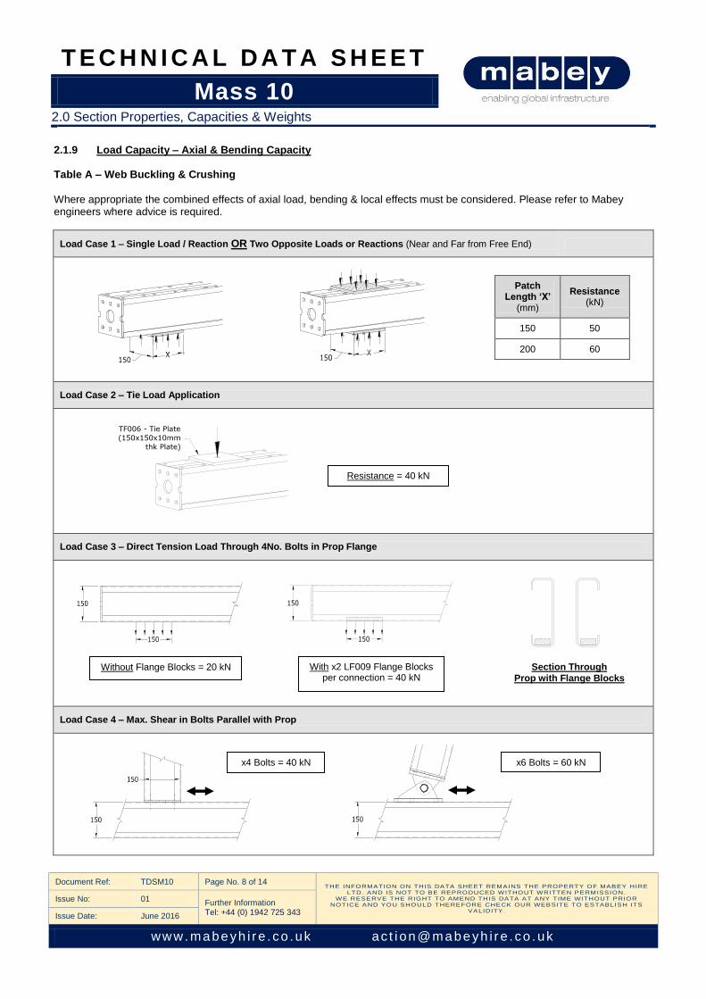
2.1.9 Load Capacity – Axial & Bending Capacity Table A – Web Buckling & Crushing
Where appropriate the combined effects of axial load, bending & local effects must be considered. Please refer to Mabey engineers where advice is required.
Load Case 1 – Single Load / Reaction OR Two Opposite Loads or Reactions (Near and Far from Free End)
Patch Length ‘X’
(mm)
Resistance (kN)
150 50
200 60
Load Case 2 – Tie Load Application
Load Case 3 – Direct Tension Load Through 4No. Bolts in Prop Flange
Load Case 4 – Max. Shear in Bolts Parallel with Prop
With x2 LF009 Flange Blocks per connection = 40 kN
x4 Bolts = 40 kN x6 Bolts = 60 kN
Section Through
Prop with Flange Blocks Without Flange Blocks = 20 kN
2.0 Section Properties, Capacities & Weights
Resistance = 40 kN
T E C H N I C A L D A T A S H E E T
Mass 10
Document Ref: TDSM10 Page No. 9 of 14 THE INFORMATION ON THIS DATA SHEET REMAINS THE PROPERTY OF MABEY HIRE
LTD. AND IS NOT TO BE REPRODUCED WITHOUT WRITTEN PERMISSION. WE RESERVE THE RIGHT TO AMEND THIS DATA AT ANY TIME WITHOUT PRIOR
NOTICE AND YOU SHOULD THEREFORE CHECK OUR WEBSITE TO ESTABLISH ITS VALIDITY .
Issue No: 01 Further Information Tel: +44 (0) 1942 725 343 Issue Date: June 2016
www. mabeyh i r e . co .uk ac t i on@mabeyh i r e . co . uk
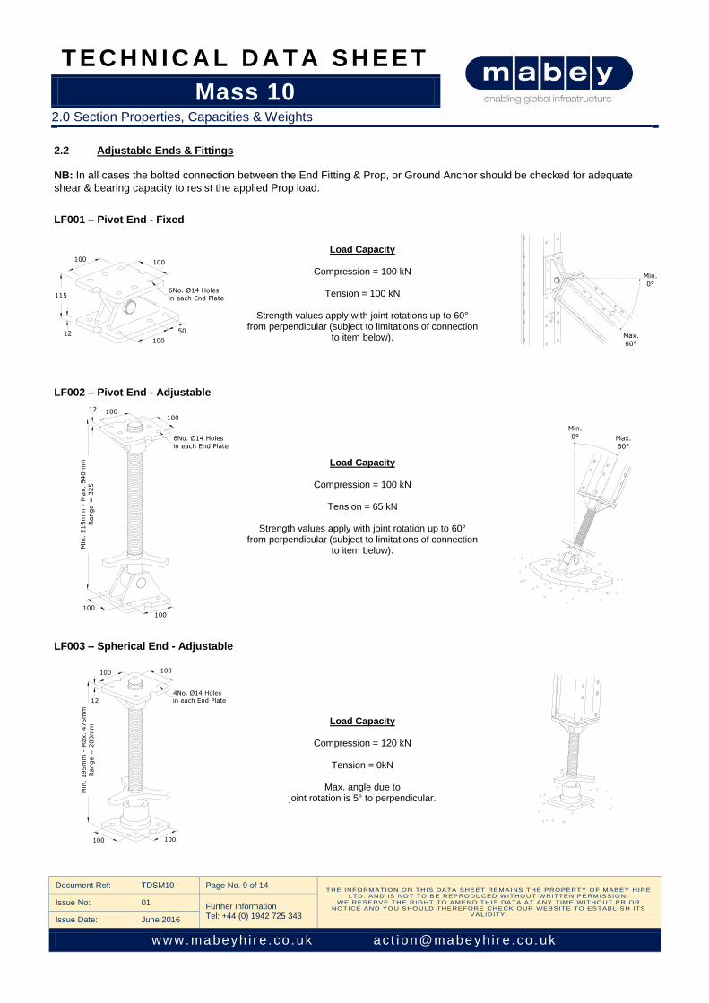
2.2 Adjustable Ends & Fittings NB: In all cases the bolted connection between the End Fitting & Prop, or Ground Anchor should be checked for adequate
shear & bearing capacity to resist the applied Prop load.
LF001 – Pivot End - Fixed
Load Capacity
Compression = 100 kN
Tension = 100 kN
Strength values apply with joint rotations up to 60°
from perpendicular (subject to limitations of connection to item below).
LF002 – Pivot End - Adjustable
Load Capacity
Compression = 100 kN
Tension = 65 kN
Strength values apply with joint rotation up to 60° from perpendicular (subject to limitations of connection
to item below).
LF003 – Spherical End - Adjustable
Load Capacity
Compression = 120 kN
Tension = 0kN
Max. angle due to joint rotation is 5° to perpendicular.
2.0 Section Properties, Capacities & Weights
100 100
100
50
115
12
6No. Ø14 Holes
in each End Plate
100100
6No. Ø14 Holes
in each End Plate
100100
Min
. 215m
m -
Max.
540m
m
Range =
325
12
Min.
0° Max.
60°
Min.
0°
Max.
60°

T E C H N I C A L D A T A S H E E T
Mass 10
Document Ref: TDSM10 Page No. 10 of 14 THE INFORMATION ON THIS DATA SHEET REMAINS THE PROPERTY OF MABEY HIRE
LTD. AND IS NOT TO BE REPRODUCED WITHOUT WRITTEN PERMISSION. WE RESERVE THE RIGHT TO AMEND THIS DATA AT ANY TIME WITHOUT PRIOR
NOTICE AND YOU SHOULD THEREFORE CHECK OUR WEBSITE TO ESTABLISH ITS VALIDITY .
Issue No: 01 Further Information Tel: +44 (0) 1942 725 343 Issue Date: June 2016
www. mabeyh i r e . co .uk ac t i on@mabeyh i r e . co . uk
2.2 Adjustable Ends & Fittings Continued
LF004 – Holding Down Baseplate LF005 – Scaffold Coupler LF006 – Location Plate
LF007 – Header Beam Connector LF008 - Washer LF009 – Flange Block
LF010 – Universal Plumbing Prop Adaptor
2.0 Section Properties, Capacities & Weights
Material Grade: S355J2

T E C H N I C A L D A T A S H E E T
Mass 10
Document Ref: TDSM10 Page No. 11 of 14 THE INFORMATION ON THIS DATA SHEET REMAINS THE PROPERTY OF MABEY HIRE
LTD. AND IS NOT TO BE REPRODUCED WITHOUT WRITTEN PERMISSION. WE RESERVE THE RIGHT TO AMEND THIS DATA AT ANY TIME WITHOUT PRIOR
NOTICE AND YOU SHOULD THEREFORE CHECK OUR WEBSITE TO ESTABLISH ITS VALIDITY .
Issue No: 01 Further Information Tel: +44 (0) 1942 725 343 Issue Date: June 2016
www. mabeyh i r e . co .uk ac t i on@mabeyh i r e . co . uk
2.3 Shutter Beams
2.3.1 Details & Section Properties
The Mabey Hire steel Shutter Beam is equivalent to a 9” x 3” SC4 timber waler.
2.4 Plumbing Prop
2.4.1 Details & Properties
The Mass 10 application for this item is as a lightweight plumbing prop. PP-00
Comp. (kN) Tens. (kN)
S.W.L. at Min. length 35 20*
S.W.L. at Max. length 35 20*
* Limited by Mass 10 Prop Section properties.
2.0 Section Properties, Capacities & Weights
PP-01
Comp. (kN) Tens. (kN)
S.W.L. at Min. length 35 20*
S.W.L. at Max. length 17 17
S.W.L. at Min. length = 35 kN S.W.L. at Max. length = 17 kN
2.0 Section Properties, Capacities & Weights

T E C H N I C A L D A T A S H E E T
Mass 10
Document Ref: TDSM10 Page No. 12 of 14 THE INFORMATION ON THIS DATA SHEET REMAINS THE PROPERTY OF MABEY HIRE
LTD. AND IS NOT TO BE REPRODUCED WITHOUT WRITTEN PERMISSION. WE RESERVE THE RIGHT TO AMEND THIS DATA AT ANY TIME WITHOUT PRIOR
NOTICE AND YOU SHOULD THEREFORE CHECK OUR WEBSITE TO ESTABLISH ITS VALIDITY .
Issue No: 01 Further Information Tel: +44 (0) 1942 725 343 Issue Date: June 2016
www. mabeyh i r e . co .uk ac t i on@mabeyh i r e . co . uk
2.5 Needle Beams
2.5.1 Section Properties and Capacities
2.0 Section Properties, Capacities & Weights
Central Point Load on 152 x 152 x 37 kg/m U.C.
Needle Beam N-004 & N-014
Central Point Load on 203 x 203 x 60 kg/m U.C.
Needle Beam N-009 Central Point Load on 254 x 254 x 107 kg/m U.C.
Needle Beam N-008, N-010 & N-012
Notes: 1. The graphs extend to the point where one of the following limits is reached: (a) The central point load reaches its maximum safe value. (b) The deflection reaches 3.0mm. (c) The central point load reaches 200 kN.
2. Under controlled design conditions, e.g. with props of a higher capacity, it may be possible to work above these limits. Please contact Mabey Hire Engineers for assistance.

T E C H N I C A L D A T A S H E E T
Mass 10
Document Ref: TDSM10 Page No. 13 of 14 THE INFORMATION ON THIS DATA SHEET REMAINS THE PROPERTY OF MABEY HIRE
LTD. AND IS NOT TO BE REPRODUCED WITHOUT WRITTEN PERMISSION. WE RESERVE THE RIGHT TO AMEND THIS DATA AT ANY TIME WITHOUT PRIOR
NOTICE AND YOU SHOULD THEREFORE CHECK OUR WEBSITE TO ESTABLISH ITS VALIDITY .
Issue No: 01 Further Information Tel: +44 (0) 1942 725 343 Issue Date: June 2016
www. mabeyh i r e . co .uk ac t i on@mabeyh i r e . co . uk
2.5.2 Typical Configurations
Lindapter Fixing
(Actual Fixing assembly is dependent on Needle Beam UC size)
2.0 Section Properties, Capacities & Weights
Needle Beam to Prop Header Beam Connection
Using Location Plate
Needle Beam to Prop Connection - Fixed
Needle Beam to Prop Connection – Not Fixed

T E C H N I C A L D A T A S H E E T
Mass 10
Document Ref: TDSM10 Page No. 14 of 14 THE INFORMATION ON THIS DATA SHEET REMAINS THE PROPERTY OF MABEY HIRE
LTD. AND IS NOT TO BE REPRODUCED WITHOUT WRITTEN PERMISSION. WE RESERVE THE RIGHT TO AMEND THIS DATA AT ANY TIME WITHOUT PRIOR
NOTICE AND YOU SHOULD THEREFORE CHECK OUR WEBSITE TO ESTABLISH ITS VALIDITY .
Issue No: 01 Further Information Tel: +44 (0) 1942 725 343 Issue Date: June 2016
www. mabeyh i r e . co .uk ac t i on@mabeyh i r e . co . uk
3.1 Equipment List
3.2 Bolt Application Table
NB: 1. All metric hexagon bolts are Grade 8.8 and countersunk (CSK) bolts are Grade 10.9.
2. If washers are required they should be ordered separately & used under the Nut only. 3. Refer to Mass 10 User Guide for further connection details.
Part No. Description Weight
(Kg) Part No. Description
Weight (Kg)
LP015 150mm Prop Unit 4.5 LF003 Pivot End - Adjustable 15.6
LP030 300mm Prop Unit 6.6 LF004 Holding Down Baseplate 19.2
LP060 600mm Prop Unit 10.6 LF005 Half Coupler Scaffold Clamp 0.6
LP090 900mm Prop Unit 15.5 LF006 Location Plate 5.7
LP120 1200mm Prop Unit 19.7 LF007 Header Beam Connector 7.8
LP180 1800mm Prop Unit 28.4 LF008 Washer 0.2
LP270 2700mm Prop Unit 41.8 LF009 Flange Block 0.7
LF010 Universal Plumbing Prop Adaptor 5.4
LF001 Pivot End - Fixed 7.9
LF002 Spherical End - Adjustable 14.8
Connection Type Bolt Details
Prop Flange Prop Flange Prop Flange Prop Flange Prop Flange
to to to to to
Prop Flange Prop End Fixed Swivel Unit (LF001) Spherical End (LF002) Adjustable Pivot (LF003)
M12 x 30mm long Bolt & Nut
Prop End Plate Prop End Plate Prop End Plate Prop End Plate
to to to to
Prop End Plate Fixed Swivel Unit (LF001) Spherical End (LF002) Adjustable Pivot (LF003)
M12 x 40mm long Bolt & Nut
Baseplate (LF004) to to to
Prop End Spherical End (LF002) Adjustable Pivot (LF003)
M12 x 55mm CSK Bolt & Nut
3.0 Equipment List
3.0 Equipment List & Bolt Application Table
3.0 Equipment List