Technical Instructions - SCC Inc Siemens Combustion ... · Technical Instructions SKPx5.xxxUx...
25
Siemens AG Building Technologies Division SKPx5 Series Technical Instructions Document No. 7643 SKPx5.xxxUx February 14, 2017 SKPx5.xxxUx Gas Valve Actuator with Safety Shutoff Function SKP15.xxxUx SKP25.xxxUx SKP55.xxxUx SKP75.xxxUx ISO 9001 and 14000 REGISTERED FIRM Only when assembled to series VGxxx.xxxU gas valves General description SKPx5.xxxUx electro‐hydraulic actuators are used in combination with VGxxx.xxxU gas valve bodies to provide slow opening, fast closing safety shut‐off and, depending on model gas pressure regulation and air/gas ratio control for industrial and commercial burner applications. Since safety shut‐off, constant pressure regulation or air/gas ratio control can be performed by a single valve, fewer gas train components and fittings are required to assemble a gas train. This significantly reduces both the size and weight of the gas train. The total pressure drop across the gas train arrangement is reduced, allowing for the use of smaller diameter gas trains in most applications. The compact SKPx5.xxxUx actuator opens slowly when powered and closes immediately upon power interruption. The modular design allows the SKPx5.xxxUx to be used in combination with all VGxxx.xxxU gas valves bodies from ½" to 6" sizes. The actuator can easily be mounted on the square flange of any VGxxx.xxxU valve with four pre‐mounted screws. No gaskets or seals are required when mounting the actuator. A visible position indicator on the front of the actuator displays the entire stroke of the valve. A light indicates when the actuator is powered.
Transcript of Technical Instructions - SCC Inc Siemens Combustion ... · Technical Instructions SKPx5.xxxUx...

Siemens AG Building Technologies Division
SKPx5 Series
Technical Instructions Document No. 7643
SKPx5.xxxUx February 14, 2017
SKPx5.xxxUx Gas Valve Actuator with Safety Shutoff Function
SKP15.xxxUx SKP25.xxxUx SKP55.xxxUx SKP75.xxxUx
ISO 9001 and 14000 REGISTERED FIRM
Only when assembled to series VGxxx.xxxU gas valves
General description SKPx5.xxxUx electro‐hydraulic actuators are used in combination with VGxxx.xxxU gas valve bodies to provide slow opening, fast closing safety shut‐off and, depending on model gas pressure regulation and air/gas ratio control for industrial and commercial burner applications. Since safety shut‐off, constant pressure regulation or air/gas ratio control can be performed by a single valve, fewer gas train components and fittings are required to assemble a gas train. This significantly reduces both the size and weight of the gas train. The total pressure drop across the gas train arrangement is reduced, allowing for the use of smaller diameter gas trains in most applications. The compact SKPx5.xxxUx actuator opens slowly when powered and closes immediately upon power interruption. The modular design allows the SKPx5.xxxUx to be used in combination with all VGxxx.xxxU gas valves bodies from ½" to 6" sizes. The actuator can easily be mounted on the square flange of any VGxxx.xxxU valve with four pre‐mounted screws. No gaskets or seals are required when mounting the actuator. A visible position indicator on the front of the actuator displays the entire stroke of the valve. A light indicates when the actuator is powered.

Technical Instructions SKPx5.xxxUx Electro‐hydraulic actuators
Document Number CC1N7643us
February 14, 2017
Page 2 Siemens AG Building Technologies Division
Application All SKPx5.xxxUx electro‐hydraulic actuators combine with VGxxx.xxxU gas valves to provide safety shut‐off control for industrial and commercial burner applications. VGxxx.xxxU or VRD40.xxxU gas valve bodies to be ordered separately.
Type of valve Medium Data Sheet
VGG10.xxxU Natural gas, air N7636us
VGD20.xxxU VGD4x.xxxU
Natural gas, air N7631us
VRD40.xxxU Biogases Recycling gases Air
N7649us
SKP25.xxxUx The SKP25.xxxUx controls the burner manifold gas pressure according to a fixed setpoint. The SKP25.xxxUx can also be applied as a 1:1 air/gas proportionator or zero governor.
SKP55.xxxUx The SKP55.xxxUx actuator controls the pressure difference across a restriction in the gas supply line as a function of the pressure difference across a restriction in the air supply duct, so that the air/gas ratio remains constant irrespective of air volume changes. There is no need for an upstream constant pressure regulator when using an SKP55.xxxUx actuator within the applicable pressure range of the VGxxx.xxxU valve body.
SKP75.xxxUx The SKP75.xxxUx controls the burner manifold gas pressure as a function of the combustion air pressure. There is no need for an upstream constant pressure regulator when using an SKP75.xxxUx actuator within the acceptable pressure range of the VGxxx.xxxU valve body. If the combustion air pressure exceeds the permissible value of 12" or 20" w.c. (see Specifications), the pressure must be reduced by means of a pressure reducing T‐fitting AGA78.

SKPx5.xxxUx Electro‐hydraulic actuators Technical Instructions
Document Number CC1N7643us
February 14, 2017
Siemens AG Building Technologies Division Page 3
Features SKPx5.xxxUx
• UL listed, FM approved, CSA certified, IRI approval, and ISO 9001 certified. European, Australian and Japanese approved versions available. • Proof of Closure with Over Travel (POC) option. • Optional NEMA 4 protection. • Visual position indication. • "Power on" indication light. • Quick connect wiring terminals. • Optional adjustable auxiliary switch. • Modular design with 360° actuator rotation for easy field wiring and installation. •Low (10 VA typical), power consumption.
SKP25.xxxUx • Safety shut‐off function and pressure regulating function in one compact unit. • Applicable as 1:1 air/gas proportionator or zero governor. • Accurate pressure control characteristics, and zero offset (drop). • Integral regulation leak limiter. • Excellent tracking characteristic.
SKP55.xxxUx • Safety shut‐off function, pressure regulating function and air/gas P control in one compact unit. • Simplifies commissioning and reduces start‐up time for: o Recuperative burners with combustion air preheating. o Burners with continuously variable air or gas nozzle openings in the burner head. o Burners where either the air or gas pressure is not representative of the actual flow. o Burners with negative combustion air pressure levels. • Maintains air/gas ratio when the airflow is disrupted. • Automatic compensation for combustion chamber back pressure fluctuations.
SKP75.xxxUx • Safety shut‐off function, pressure regulating function and air/gas ratio control in one device. • Compensation for air temperature fluctuations. • Automatic compensation for combustion chamber back pressure fluctuations.
Technical Instructions SKPx5.xxxUx Electro‐hydraulic actuators
Document Number CC1N7643us
February 14, 2017
Page 4 Siemens AG Building Technologies Division
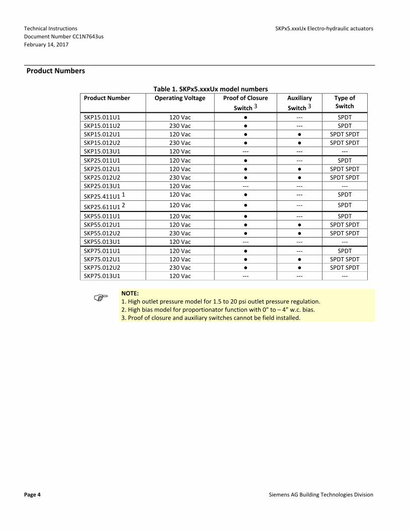
Product Numbers
Table 1. SKPx5.xxxUx model numbers
Product Number Operating Voltage Proof of Closure
Switch 3
Auxiliary
Switch 3
Type of Switch
SKP15.011U1 120 Vac ● ‐‐‐ SPDT
SKP15.011U2 230 Vac ● ‐‐‐ SPDT
SKP15.012U1 120 Vac ● ● SPDT SPDT
SKP15.012U2 230 Vac ● ● SPDT SPDT
SKP15.013U1 120 Vac ‐‐‐ ‐‐‐ ‐‐‐
SKP25.011U1 120 Vac ● ‐‐‐ SPDT
SKP25.012U1 120 Vac ● ● SPDT SPDT
SKP25.012U2 230 Vac ● ● SPDT SPDT
SKP25.013U1 120 Vac ‐‐‐ ‐‐‐ ‐‐‐
SKP25.411U1 1 120 Vac ● ‐‐‐ SPDT
SKP25.611U1 2 120 Vac ● ‐‐‐ SPDT
SKP55.011U1 120 Vac ● ‐‐‐ SPDT
SKP55.012U1 120 Vac ● ● SPDT SPDT
SKP55.012U2 230 Vac ● ● SPDT SPDT
SKP55.013U1 120 Vac ‐‐‐ ‐‐‐ ‐‐‐
SKP75.011U1 120 Vac ● ‐‐‐ SPDT SKP75.012U1 120 Vac ● ● SPDT SPDT SKP75.012U2 230 Vac ● ● SPDT SPDT SKP75.013U1 120 Vac ‐‐‐ ‐‐‐ ‐‐‐
NOTE: 1. High outlet pressure model for 1.5 to 20 psi outlet pressure regulation. 2. High bias model for proportionator function with 0" to – 4" w.c. bias. 3. Proof of closure and auxiliary switches cannot be field installed.

SKPx5.xxxUx Electro‐hydraulic actuators Technical Instructions
Document Number CC1N7643us
February 14, 2017
Siemens AG Building Technologies Division Page 5
Accessories
AGA22 Yellow setpoint spring for 6” to 48” w.c. (1.5 to 10 psi for SKP25.411U1)
AGA23 Red setpoint spring for 40” to 100” w.c. (8.5 to 20 psi for SKP25.411U1)
AGA25.2
Damping orifice for mounting into vent connection of SKP25.0xxUx or SKP25.4xxUx models
AGA28 Black bias spring to install if SKP25.0xxUx for ‐0.4" to 0.4" w.c. is used as proportionator or zero governor
AGA29 Unpainted setpoint spring for 0" to 8.5" w.c. (included in SKP25.0xxUx as standard)
AGA66
Sealing gasket to provide NEMA 3, NEMA 3R, and NEMA 4 protection. Gasket kit to mount SKPxx.xxxUx
Placed between actuator SKPxx.xxxUx and valve VGxxx.xxxU or valve VRD40.xxxU
Increases degree of protection from IP54 to IP65
Refer to Mounting Instruction M7643.2 (74 319 0421 0)
AGA75.U1/4NPT
Damping throttle for SKP55.xxxUx / SKP75.xxxUx, US thread ¼“ NPT
Optional, pipe connection for 6 mm
Refer to Mounting Instructions 4 319 2078 0
AGA78
Air pressure reducing T‐fitting
AGA30.7
Adaptation to SKP25.xxxUx For motorized pressure correction Siemens part number: S55851‐Z401‐A100 See Mounting Instructions A5W00000658.
SAS...
Motorized setpoint adjuster for SKP25.0xxUx
For 5.5 mm stroke
See Data Sheet N4581 and Mounting Instructions A5W00000658 (M7643)
Technical Instructions SKPx5.xxxUx Electro‐hydraulic actuators
Document Number CC1N7643us
February 14, 2017
Page 6 Siemens AG Building Technologies Division
Specifications
Agency approvals As safety shut‐off valve UL/429, FM/7400, ANSI Z21.21/CSA6.5 C/I Agency marks apply only for SKPx5.xxxUx actuators with VGxxx.xxxU series gas valve bodies.
SKP25.xxxUx, SKP55.xxxUx and SKP75.xxxUx
As a pressure regulator ANSI Z21.18/CSA 6.3
Power supply Operating voltage 120 Vac + 10% to ‐15% 230 Vac + 10% to ‐15%
Operating frequency 50 to 60 Hz + 6%
Power consumption 13,5 VA
Duty cycle Continuous (100%)
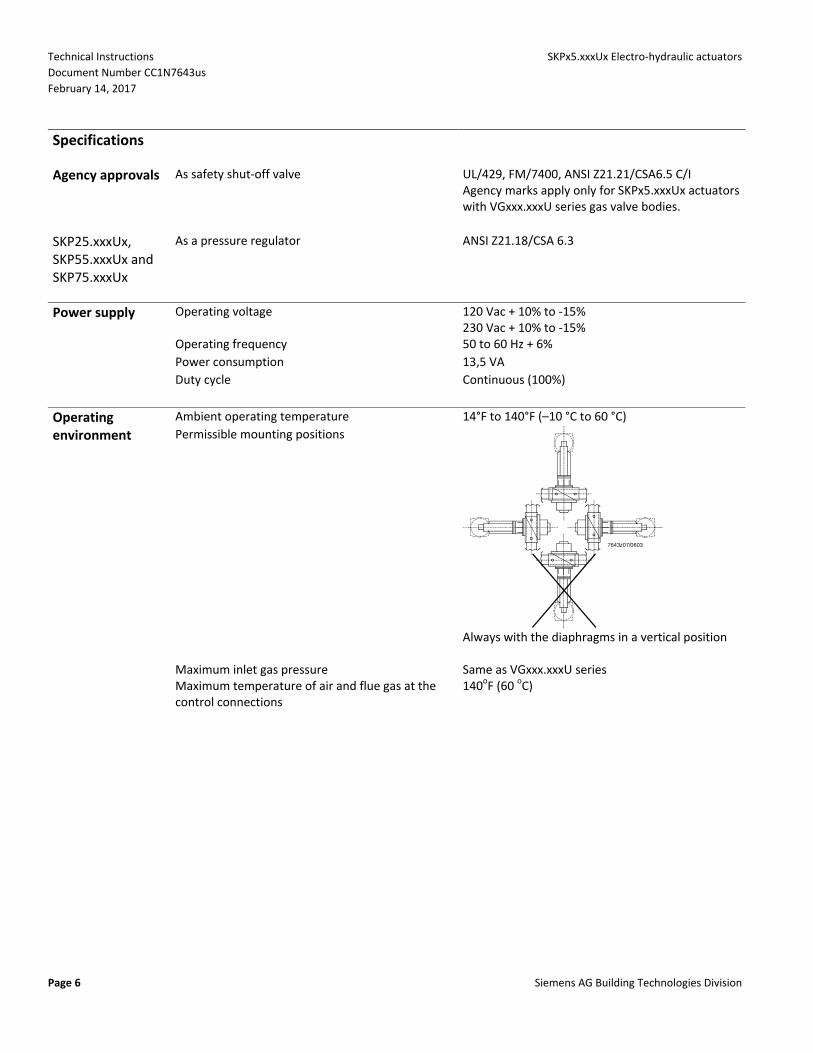
Operating Ambient operating temperature 14°F to 140°F (–10 °C to 60 °C)
environment Permissible mounting positions
7643z07/0603
Always with the diaphragms in a vertical position
Maximum inlet gas pressure Same as VGxxx.xxxU series Maximum temperature of air and flue gas at the
control connections 140oF (60 oC)

SKPx5.xxxUx Electro‐hydraulic actuators Technical Instructions
Document Number CC1N7643us
February 14, 2017
Siemens AG Building Technologies Division Page 7
Specifications Continued
Physical Weight
characteristics SKP15.xxxUx 2.4 lb (1.1 kg)
SKP25.xxxUx 3.5 lb (1.6 kg)
SKP55.xxxUx 4.2 lb (1.9 kg)
SKP75.xxxUx 5.1 lb (2.3 kg)
Enclosure NEMA 1, 2, 5, and 12 NEMA 3, 3R, and 4 with optional AGA66 sealing gasket (mounted with VGG10.xxxU / VGDxx.xxxU / VRD40.xxxU valves)
Dimensions See Figures 12...16
Specification for valve bodies See gas valve Technical Instructions, for VGG10.xxxxU N7636us, for VGDxx.xxxU N7631us, for VRD40.xxxU N7649us
Connections Conduit connection Two 1/2‐inch NPSM threaded knock‐outs
Electrical connection Spring‐loaded terminals for 14 AWG wires
Gas connection 1/4" NPT (see Installation notes)
Air connection 1/4" NPT (see Installation notes)
Gas pressure test connection Hose barb with close‐off screw
SKP75.xxxUx Combustion chamber pressure test connection Hose barb with close‐off screw
Operating Opening speed, typical (approx. 2 mm/s) The opening time for full stroke varies with
characteristics valve size
Closing time <0.8 seconds slower opening speed at lower temperature
Technical Instructions SKPx5.xxxUx Electro‐hydraulic actuators
Document Number CC1N7643us
February 14, 2017
Page 8 Siemens AG Building Technologies Division
Specifications Continued
Operation / installation
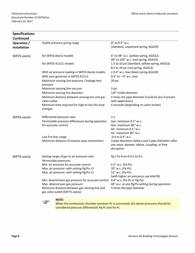
Outlet pressure spring range 0" to 8.5" w.c. (standard, unpainted spring, AGA29)
SKP25.xxxUx for SKP25.0xxUx models 6" to 48" w.c. (yellow spring, AGA22) 40" to 100" w.c. (red spring, AGA23)
for SKP25.411U1 models 1.5 to 10 psi (standard, yellow spring, AGA22)
8.5 to 20 psi (red spring, AGA23)
With air pressure loading in SKP25.0xxUx models ± 0.4" w.c. bias (black spring AGA28)
With zero governor in SKP25.611U1 0.4" to – 4" w.c. bias
Maximum sensing line pressure / leakage test pressure
20 psi
Maximum sensing line vacuum 3 psi
Minimum sensing line diameter 1/4" inside diameter
Minimum distance between sensing line and gas valve outlet
5 times the pipe diameter (could be less if proven with application)
Minimum time required for high to low fire load changes
4 seconds (depending on valve stroke)
SKP55.xxxUx Differential pressure ratio 1:1
Permissible pressure differences during operation for accurate control
Gas: minimum 0.1" w.c. Gas: maximum 80" w.c. Air: minimum 0.1" w.c. Air: maximum 80" w.c.
Low fire bias range ‐0.4 to 0.4" w.c. Minimum distance of impulse pipe connections 3 pipe diameters before and 5 pipe diameters after
any valve, damper, elbow, coupling, or flow disruption
SKP75.xxxUx Setting range of gas to air pressure ratio Pg / Pa from 0.4:1 to 9:1
Permissible pressures: Min. air pressure for accurate control 0.2" w.c. (Pa‐Pc) Max. air pressure: with setting Pg/Pa <2 20" w.c. (Pa‐Pc) Max. air pressure: with setting Pg/Pa >2 12" w.c. (Pa‐Pc)
(with higher air pressures use AGA78) Min. downstream gas pressure for accurate control 0.4" w.c. (Pa‐Pc or Pg‐Pa) Max. downstream gas pressure 40" w.c. at any Pg/Pa setting during operation Minimum distance between gas sensing line and
gas valve outlet (SKP75.xxxUx) 5 times the pipe diameter
NOTE: When the combustion chamber pressure Pc is connected, the above pressures should be considered pressure differentials Pg‐Pc and Pa‐Pc.

SKPx5.xxxUx Electro‐hydraulic actuators Technical Instructions
Document Number CC1N7643us
February 14, 2017
Siemens AG Building Technologies Division Page 9
Specifications Continued
Auxiliary Proof of closure switch Non‐adjustable
features Setting range of auxiliary switch 40% to 100% of stroke
Switch rating 4 A (2 A, cos = 0.3)
NOTE: AUX‐circuit not for SELV (safety extra low voltage)!
Operation (see Figure 1)
Safety shut‐off function
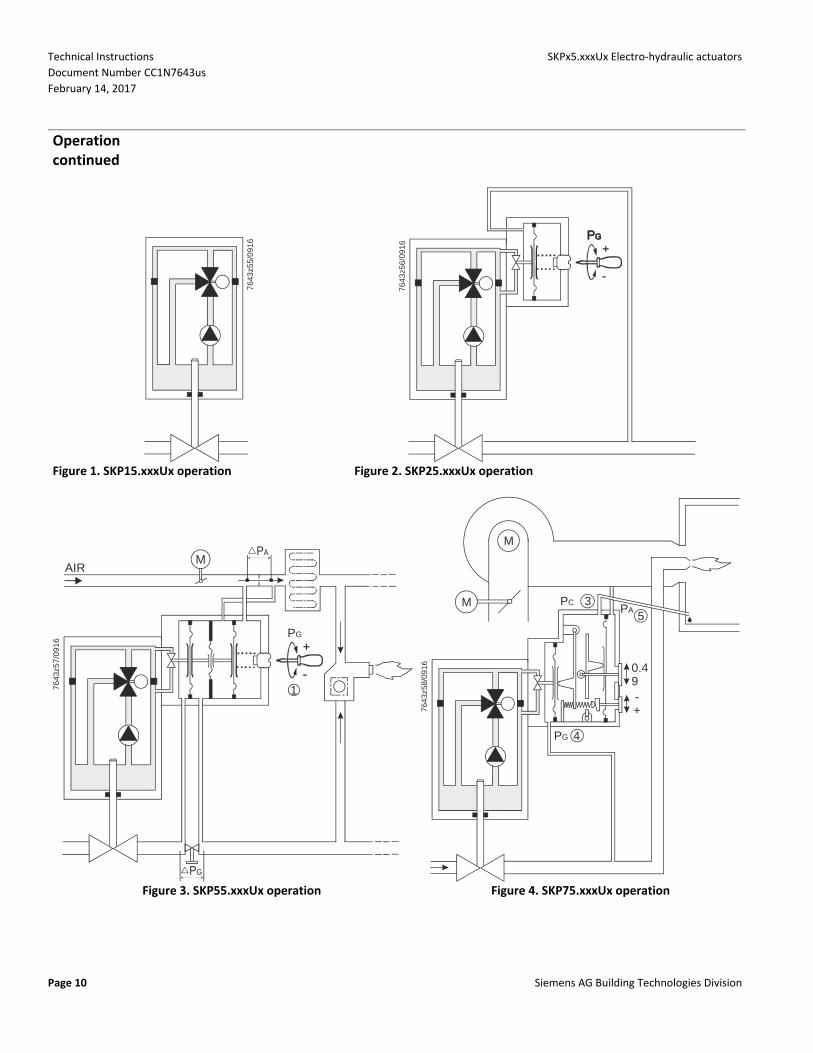
The electro‐hydraulic actuator consists of a cylinder filled with oil, a piston containing an electric oscillating pump, and a relief system. When power is supplied to the actuator, the relief system closes, and the pump moves oil from the reservoir into the pressure chamber. This action causes the piston to move downward in the cylinder, opening the gas valve. When power to the actuator is interrupted, the relief system opens and the gas valve closes in less than 0.8 seconds. A position indicator, visible through the transparent window of the terminal box cover, shows the entire possible stroke range of the actuator. A light, which is visible through the lower left transparent window of the terminal box cover, indicates when the actuator receives power. An optional, non‐adjustable SPDT proof of closure over travel switch signals the closed position after the gas valve has closed. An optional SPDT auxiliary switch is adjustable between 40% and 100% of the stroke. The adjustment screw and scale are located on the right side in the terminal box, and are visible through the transparent window of the terminal box cover. The sealing gasket, AGA66, can be installed between the actuator and the gas valve to provide NEMA 3, 3R, and 4 protection rating for VGG10.xxxU / VGDxx.xxxU / VRD40.xxxU valves.
Technical Instructions SKPx5.xxxUx Electro‐hydraulic actuators
Document Number CC1N7643us
February 14, 2017
Page 10 Siemens AG Building Technologies Division
Operation continued
76
43z5
5/09
16
Figure 1. SKP15.xxxUx operation
764
3z56
/09
16
Figure 2. SKP25.xxxUx operation
76
43z
57
/09
16
PG
1
MAIR
Figure 3. SKP55.xxxUx operation
764
3z58
/091
6
M
M PC 3PA
5
0.49-+
PG 4
Figure 4. SKP75.xxxUx operation

SKPx5.xxxUx Electro‐hydraulic actuators Technical Instructions
Document Number CC1N7643us
February 14, 2017
Siemens AG Building Technologies Division Page 11
Operation continued (see Figure 2)
Regulating function SKP25.xxxUx The outlet gas pressure sensing line is connected to the pressure regulator housing. The outlet
pressure acts on the regulator diaphragm. The diaphragm is opposed by an adjustable setpoint spring force, which represents the desired gas pressure value. The movement of the diaphragm modulates a hydraulic bypass valve connecting the pressure chamber to the hydraulic fluid reservoir. When the outlet gas pressure is lower than the desired value, the bypass valve is closed by the movement of the diaphragm, causing the actuator piston to open the gas valve. The opposite occurs when the outlet gas pressure is higher than the desired value; the diaphragm moves to open the bypass causing the actuator piston to close the gas valve. The movement of the actuator piston stops once the outlet gas pressure is equal to the setpoint. In this position the bypass valve is partially open so that the oil flow supplied by the pump is identical to the return flow. Unlike the conventional direct acting regulators, the SKP25.xxxUx servo operated regulating system displays virtually zero droop (offset) across the turndown range. The SKP25.0xxUx models may be applied as a 1:1 air/gas proportionator or as a zero governor. For either application, the standard spring has to be replaced with AGA28 spring, which allows adjusting the bias between +0.4" to ‐0.4" w.c. For proportionator operation, the air pressure sensing line must be connected to the port marked “AIR". High bias model SKP25.611U1 is a 1:1 air/gas proportionator with a factory installed spring for 0.4" to ‐4.0" w.c. bias.
NOTE: 1. To avoid oscillation, do not oversize the VGxxx.xxxU valve body (see Technical Instructions, N7636us and N7631us). 2. SKP25.4xxUx models must not be used as proportionators.

Technical Instructions SKPx5.xxxUx Electro‐hydraulic actuators
Document Number CC1N7643us
February 14, 2017
Page 12 Siemens AG Building Technologies Division
Operation continued (see Figure 3)
SKP55.xxxUx During the burner pre‐purge period, when the gas valve is closed, only the air pressure difference acts on the regulator causing the air diaphragm to move and close the regulating hydraulic bypass valve. When the actuator is powered, the gas valve begins to open. The downstream gas pressure difference immediately begins to increase until the gas pressure difference is in balance with the air pressure difference (in accordance with the pressure ratio adjusted on the regulator). The bypass valve is now partially open so that the oil flow supplied by the pump is identical to the return flow. If, for example, heat demand increases, the air damper opens further increasing the differential air pressure. The SKP55.xxxUx air diaphragm moves and causes the bypass valve to close and the gas valve to open further. The opening of the gas valve increases the differential gas pressure moving the gas diaphragm to the right until balance is restored and the flow supplied by the pump is once again identical to the return flow through the regulator bypass. Unlike conventional direct acting regulators, the SKP55.xxxUx servo operated regulating system displays virtually zero drop (offset) across the turndown range.
NOTE: The SKP55.xxxUx / VGxxx.xxxU is a 1:1 differential pressure air/gas ratio controller. This means that the control adjusts the same pressure difference on the gas side as it senses on the air side. Any other gas to air ratio adjustment will require a modification to one of the restrictions or the installation of an adjustable orifice (this is normally an adjustable metering orifice in the gas line). For this purpose the VGxxx.xxxU gas valve with manual operation kit AGA61 may be used. See gas valve Technical Instructions N7636us and N7631us.
NOTE: 1. For optimal performance, both the air damper and SKP55.xxxUx /VGxxx.xxxU gas valve must be installed upstream of its pressure differential orifice. For other layouts please consult your authorized Siemens AG Building Technologies Division Products sales representative. 2. To avoid oscillation, do not oversize the VGxxx.xxxU valves (see Technical Instructions N7636us and N7631us).
Many burner designs, because of reduced mixing energy at the low fire level, require increased excess
air at low fire in order to maintain optimum combustion parameters. To accommodate this requirement the SKP55.xxxUx incorporates a bias adjustment, which allows the characteristic of the regulator to be displaced either towards excess air or reduced air. Pressure fluctuations in the combustion chamber do not influence the performance of the SKP55.xxxUx air/gas ratio controller. There is no need for any compensation circuit.
SKPx5.xxxUx Electro‐hydraulic actuators Technical Instructions
Document Number CC1N7643us
February 14, 2017
Siemens AG Building Technologies Division Page 13
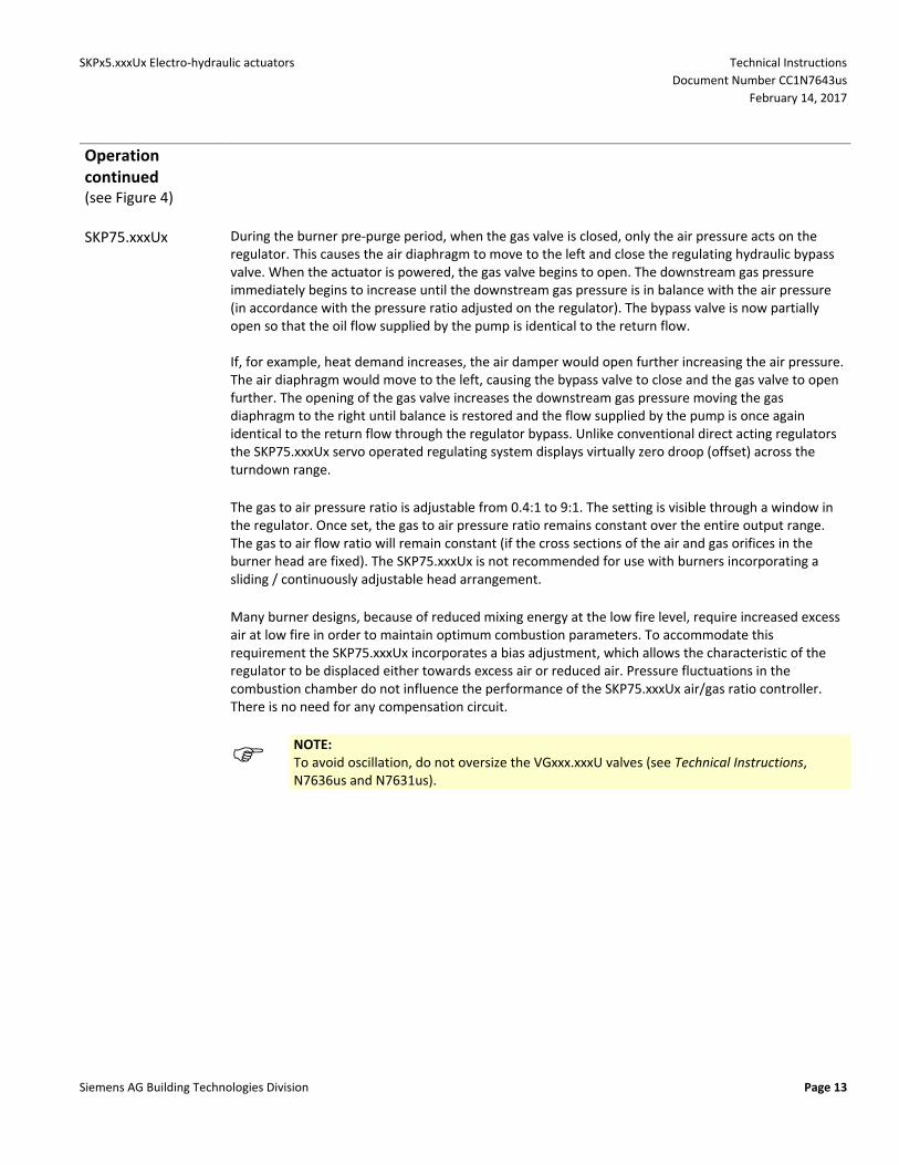
Operation continued (see Figure 4)
SKP75.xxxUx During the burner pre‐purge period, when the gas valve is closed, only the air pressure acts on the regulator. This causes the air diaphragm to move to the left and close the regulating hydraulic bypass valve. When the actuator is powered, the gas valve begins to open. The downstream gas pressure immediately begins to increase until the downstream gas pressure is in balance with the air pressure (in accordance with the pressure ratio adjusted on the regulator). The bypass valve is now partially open so that the oil flow supplied by the pump is identical to the return flow. If, for example, heat demand increases, the air damper would open further increasing the air pressure. The air diaphragm would move to the left, causing the bypass valve to close and the gas valve to open further. The opening of the gas valve increases the downstream gas pressure moving the gas diaphragm to the right until balance is restored and the flow supplied by the pump is once again identical to the return flow through the regulator bypass. Unlike conventional direct acting regulators the SKP75.xxxUx servo operated regulating system displays virtually zero droop (offset) across the turndown range.
The gas to air pressure ratio is adjustable from 0.4:1 to 9:1. The setting is visible through a window in
the regulator. Once set, the gas to air pressure ratio remains constant over the entire output range. The gas to air flow ratio will remain constant (if the cross sections of the air and gas orifices in the burner head are fixed). The SKP75.xxxUx is not recommended for use with burners incorporating a sliding / continuously adjustable head arrangement.
Many burner designs, because of reduced mixing energy at the low fire level, require increased excess
air at low fire in order to maintain optimum combustion parameters. To accommodate this requirement the SKP75.xxxUx incorporates a bias adjustment, which allows the characteristic of the regulator to be displaced either towards excess air or reduced air. Pressure fluctuations in the combustion chamber do not influence the performance of the SKP75.xxxUx air/gas ratio controller. There is no need for any compensation circuit.
NOTE: To avoid oscillation, do not oversize the VGxxx.xxxU valves (see Technical Instructions, N7636us and N7631us).
Technical Instructions SKPx5.xxxUx Electro‐hydraulic actuators
Document Number CC1N7643us
February 14, 2017
Page 14 Siemens AG Building Technologies Division
Installation
WARNING: • Personal injury or loss of life may occur if procedures are not followed as specified. • All installations must be performed by qualified personnel only. • Do not pull the actuator shaft. • The AGA66 gasket must be installed between the actuator and the gas valve body to provide NEMA 3, 3R, and 4 protection rating for VGG10.xxxU and VGDxx.xxxU valves if a liquid‐tight conduit connection is used.
NOTE: Wiring must meet all relevant electrical codes.
• The SKPx5.xxxUx actuator is directly coupled to the VGxxx.xxxU series valve body by four premounted 4 mm Allen (R) key screws. • The square mounting flange can be rotated in steps of 90° to provide four different mounting positions. The SKPx5.xxxUx actuator can be mounted in any position with the diaphragms vertical, except upside down. • The actuator can be mounted or replaced while the valve body is under pressure. • The SKPx5.xxxUx actuator has two knock‐outs for the installation of 1/2”‐14 NPSM conduit connections. • When conduit routing is connected, flexible conduit must be used. • Liquid tight flexible conduit must be used in combination with AGA66 to provide NEMA 3, 3R, and 4 protection. • The terminal marked GND, located above the wiring terminals, must be connected to the electrical ground. The pressure pick‐up connections must be flush with the inner wall of the pipe or housing in order to sense turbulence‐free pressures. The pressure pick‐up connections should be located at least 5 pipe diameters downstream of the valve, damper, elbow, coupling, orifice, or other flow disturbing fitting. Using the taps on the valve body for gas connection to the regulator may show turbulence.
SKP25.xxxUx, SKP55.xxxUx and SKP75.xxxUx
• If minimum gas pressure detection is required, the pressure switch must be mounted upstream of the regulating gas valve or if mounted downstream electrically by‐passed to ensure sufficient gas pressure before starting the burner. If mounted downstream. • The gas pressure sensing line must be at least 1/4‐inch inside diameter. • The pressure connection pipe should be as short as possible to allow the regulator to react to sudden changes.
SKP25.xxxUx Depending on the application and applicable installation regulations, measures to detect and avoid a downstream overpressure situation might be required. To avoid excessive gas pressure downstream of the regulator SKP25.xxxUx, a maximum pressure switch shall be used to switch off the SKP25.xxxUx/VGxxx.xxxU. The downstream gas pressure and the gas flow will consequently be shut off. The gas release to the environment will be limited to the period for overpressure detection and shut off (<5 seconds). In this case venting measures are not required.

SKPx5.xxxUx Electro‐hydraulic actuators Technical Instructions
Document Number CC1N7643us
February 14, 2017
Siemens AG Building Technologies Division Page 15
Installation continued
SKP55.xxxUx The pressure connection pipes should be as short as possible to allow the regulator to react to sudden changes. In cases where it is not possible to install an orifice in the air line, (e.g., lack of available air pressure) the SKP55.xxxUx actuator may be connected to the air pressure upstream of the burner and the combustion chamber pressure, using the pressure differential across the burner orifice. This arrangement is not applicable to installations utilizing combustion air preheating systems.
3
5
4
2
1
6
7643z62us/1016
Figure 5. SKP55.xxxUx Connections and adjustments 1 Adjustment of the bias (behind cap) 2 Connection for the air pressure (+) sensing line 3 Connection for the air pressure (‐) sensing line 4 Connection for the gas pressure (‐) sensing line 5 Connection for the gas pressure (+) sensing line 6 Stroke indication

Technical Instructions SKPx5.xxxUx Electro‐hydraulic actuators
Document Number CC1N7643us
February 14, 2017
Page 16 Siemens AG Building Technologies Division
Installation continued
SKP75.xxxUx • Air proving safety device normally required to guarantee minimum airflow must also be provided when using the SKP75.xxxUx. • The sensing line for the combustion chamber pressure (if needed) must be installed so that condensing flue gases cannot enter into the regulator but run back into the combustion chamber. If necessary, a water separator must be installed. • Air pressure sensing lines must be at least ¼‐inch inside diameter. For air/gas pressure ratios over three, the air and combustion pressure sensing lines must be at least 3/8‐inch inside diameter. • The SKP75.xxxUx does not work in installations with negative air pressure unless a higher negative chamber pressure is connected to the regulator.
NOTE: Wiring must meet all relevant electrical standards.
1 2
3
5
6
4
764
3z63
us/1
016
1 Adjustment and indication of the air/gas ratio 2 Adjustment and indication to the bias 3 Connection for the combustion chamber pressure sensing line 4 Connection for the gas pressure sensing line 5 Connection for the air pressure sensing line (on the front) 6 Position indication (on the front)
Figure 6. SKP75.xxxUx Connections and adjustments
SKPx5.xxxUx Electro‐hydraulic actuators Technical Instructions
Document Number CC1N7643us
February 14, 2017
Siemens AG Building Technologies Division Page 17
Start‐up
Regulator
WARNING: When firing at maximum burner capacity, ensure that the SKPx5.xxxUx / VGxxx.xxxU is not in the fully open position. If this is the case, either the gas valve is sized too small or the gas supply pressure is too low.
SKP25.xxxUx The gas outlet pressure setpoint adjustment screw is located in the center of the regulator cover. The
SKP25.0xxUx models are available with three interchangeable setpoint springs for an adjustable range of 0” to 100” w.c. The SKP25.411Ux models are available with two interchangeable setpoint springs for an adjustable range of 1.5 to 20 psi. The bias for the SKP25.611U1 model is adjustable from 0.4" to ‐4.0" w.c. (see Specifications and Table 2). Clockwise rotation of the setpoint adjustment screw increases the outlet gas pressure. The hexagonal cap must be tightened after the setpoint screw has been adjusted and may be sealed from tampering by means of a wire and lead seal.
Technical Instructions SKPx5.xxxUx Electro‐hydraulic actuators
Document Number CC1N7643us
February 14, 2017
Page 18 Siemens AG Building Technologies Division
Start‐up continued
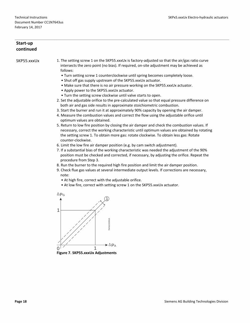
SKP55.xxxUx 1. The setting screw 1 on the SKP55.xxxUx is factory‐adjusted so that the air/gas ratio curve intersects the zero point (no bias). If required, on‐site adjustment may be achieved as follows: • Turn setting screw 1 counterclockwise until spring becomes completely loose. • Shut off gas supply upstream of the SKP55.xxxUx actuator. • Make sure that there is no air pressure working on the SKP55.xxxUx actuator. • Apply power to the SKP55.xxxUx actuator. • Turn the setting screw clockwise until valve starts to open. 2. Set the adjustable orifice to the pre‐calculated value so that equal pressure difference on both air and gas side results in approximate stoichiometric combustion. 3. Start the burner and run it at approximately 90% capacity by opening the air damper. 4. Measure the combustion values and correct the flow using the adjustable orifice until optimum values are obtained. 5. Return to low fire position by closing the air damper and check the combustion values. If necessary, correct the working characteristic until optimum values are obtained by rotating the setting screw 1. To obtain more gas: rotate clockwise. To obtain less gas: Rotate counter‐clockwise. 6. Limit the low fire air damper position (e.g. by cam switch adjustment). 7. If a substantial bias of the working characteristic was needed the adjustment of the 90% position must be checked and corrected, if necessary, by adjusting the orifice. Repeat the procedure from Step 3. 8. Run the burner to the required high fire position and limit the air damper position. 9. Check flue gas values at several intermediate output levels. If corrections are necessary, note: • At high fire, correct with the adjustable orifice. • At low fire, correct with setting screw 1 on the SKP55.xxxUx actuator.
PG
1
PA
1
0 1
7643
d15
/09
16
Figure 7. SKP55.xxxUx Adjustments

SKPx5.xxxUx Electro‐hydraulic actuators Technical Instructions
Document Number CC1N7643us
February 14, 2017
Siemens AG Building Technologies Division Page 19
Start‐up continued
SKP75.xxxUx The pressure ratio and bias adjustment screws are located on top of the regulator under a sealable cover plate. The actual settings can be seen through windows on each side of the regulator.
NOTE: The burner capacity is controlled by the position of the air damper. The combustion quality (air/gas ratio) is controlled by the settings on the regular (the + and ‐ indications relate to the change in gas flow). Adjustment in clockwise direction decreases the gas flow.
1. Set the air/gas ratio to the desired value using adjusting screw 1 (coarse setting). 2. Start the burner and run it at approximately 90% of full capacity. 3. Measure CO2 or O2 content in the flue gases and correct the ratio by adjusting screw 1 until optimum values are obtained (fine setting). 4. Return to low fire position and measure the CO2 or O2 content in the flue gases. If necessary, correct the setting by adjusting screw 2 (figure 6) until optimum values are obtained. 5. Limit the damper position for low fire operation. If considerable bias adjustment was necessary to achieve optimum combustion, repeat the procedure from step 3. 6. Run the burner to the required high fire position and limit the air damper position. 7. Check flue gas values at several intermediate output levels. If corrections are necessary, note the following: • Adjust the pressure ratio screw 1 at high operation only. • Adjust the bias screw 2 at low fire operation only. If the air pressure exceeds the maximum value of 12" or 20" w.c. (see Specifications), the pressure must be reduced with a pressure reducing T‐fitting (AGA78).
PG
1
PA
7643
d16/
0916
2
Figure 8. SKP75.xxxUx Adjustments

Technical Instructions SKPx5.xxxUx Electro‐hydraulic actuators
Document Number CC1N7643us
February 14, 2017
Page 20 Siemens AG Building Technologies Division
Pressure Reducing T‐Fitting AGA78
Figure 9. AGA78 Operation.
10 20 3010
20
30
40
50
60
70
80
90
P1
P2
D1 = 1,5 mm; D
2 = 2 mm
D1 = 1,5 mm; D2 = 1,7 mm
7643
d0
2/0
503
100
110
120
130
Figure 10. AGA78 Adjustments.
Function The air is blown out continuously into the atmosphere through the restrictor D2. The air undergoes a drop in pressure across the restrictor D1. The correlationsships are shown in the diagram (Figure 10). Example: Given p1
= 70 mbar, D1
= 1.5 mm, D2
= 1.7 mm
Find: Pressure signal P2 for SKP75.xxxUx
P2 = 26 mbar
Reducing T‐fitting AGA78 is supplied ready for mounting, complete with D1
= 1.5 mm and
D2= 1.7 mm. An additional restrictor D2with a diameter of 2 mm is included with the actuator.
Wiring and switch adjustment (See Terminal designations)
• The actuator is equipped with spring‐loaded terminals for 14 AWG wires. • The actuator has two line and two neutral terminals. Both can be connected to other devices. • Insert one wire into the opening of the terminal while pressing the lever downward with a screwdriver. Make sure that all strands insert into the opening. • Adjust the auxiliary switch (if provided) according to the wiring diagram on the label below the terminals (see Figure 11). The adjustment screw and scale are located on the right side of the terminal box, and are visible through the transparent portion of the terminal cover.
NOTE: 1. The auxiliary switch is adjustable between 40% and 100% of the stroke. The factory setting is at 40%. 2. The auxiliary switch must not be used for proof of closure detection or other safety interlock functions. 3. The Proof of Closure Switch is non‐adjustable.
Service There are no serviceable parts on the SKPx5.xxxUx series actuators. If inoperative, replace the entire actuator. Tag wires before servicing.

SKPx5.xxxUx Electro‐hydraulic actuators Technical Instructions
Document Number CC1N7643us
February 14, 2017
Siemens AG Building Technologies Division Page 21
Terminal SKPx5.011U SKPx5.012U SKPx5.013U
designations
7643z65us/0217
4A/250V
7643z66us/0217
4A/250V
7643z67us/1116 Figure 11. Terminal designations
Dimensions Dimensions in inches; millimeters [mm] in brackets
SKP15.xxxUx
3.82
[97]
1/2"-14NPSM
2.16[55]
3.20[81]
7.40
[188
]
3.15[80]
3.43 square[87]
7643m39us/1016
Figure 12. SKP15.xxxUx dimensions
Technical Instructions SKPx5.xxxUx Electro‐hydraulic actuators
Document Number CC1N7643us
February 14, 2017
Page 22 Siemens AG Building Technologies Division
Dimensions continued Dimensions in inches; millimeters [mm] in brackets
SKP25.0xxUx
1/4"Female
3.43 Square[87]
7.87
[200
]8.
70[2
21]
3.78[96] 1.30
[33]1.03[26]
1/2"-14NPSM
2.16[55]
3.20[81]
Pressuretest port0.35" [8.5] o.d.
1/4"-18 NPTFemale
1.14[36]
6.61
[168
]3.
82[9
7]
7.95
[202
]
3.15[80]
7643m40us/1016
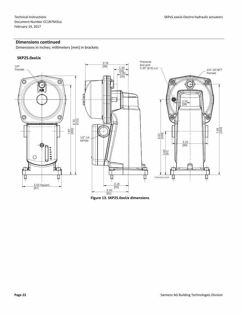
Figure 13. SKP25.0xxUx dimensions
SKPx5.xxxUx Electro‐hydraulic actuators Technical Instructions
Document Number CC1N7643us
February 14, 2017
Siemens AG Building Technologies Division Page 23
Dimensions continued Dimensions in inches; millimeters [mm] in brackets
SKP25.4xxUx
1/4"Female
8.15
[207
]8.
70[2
21]
3.43 Square[87]
2.84[72] 1.30
[33]
0.99[25]
1/2"-14NPSM
2.16[55]
3.20[81]
4.14[105]
Pressuretest port0.35" [8.5] o.d. 1/4"-18 NPT
Female
6.61
[168
]
3.15[80]
7.95
[202
]
3.82
[97]
7643m41us/1016
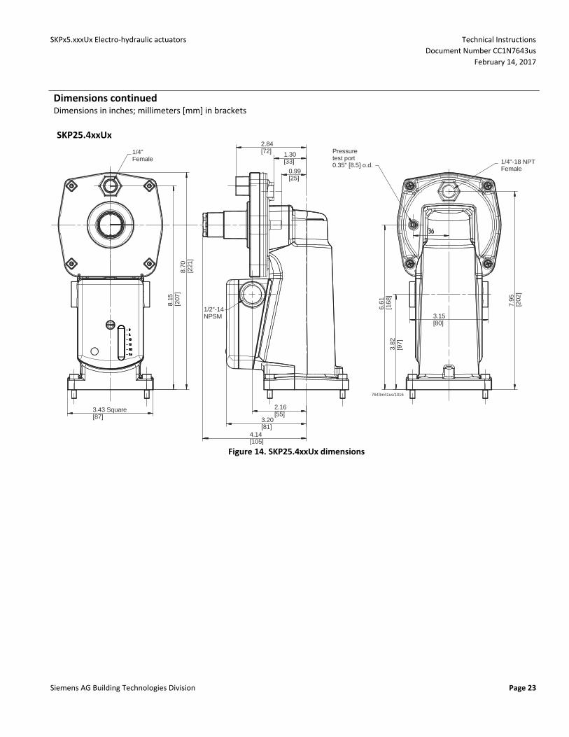
Figure 14. SKP25.4xxUx dimensions
Technical Instructions SKPx5.xxxUx Electro‐hydraulic actuators
Document Number CC1N7643us
February 14, 2017
Page 24 Siemens AG Building Technologies Division
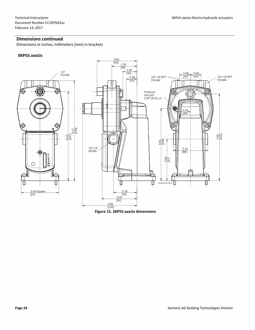
Dimensions continued Dimensions in inches; millimeters [mm] in brackets
SKP55.xxxUx
1,4"Female
9.17
[233
]
8.15
[207
]
3.43 Square[87]
3.66[93]
2.28[58]
1.30[33]
0.98[25]
1/2"-14NPSM
2.16[55]
3.20[81]
4.96[126]
1/4"-18 NPTFemale
Pressuretest port0.35" [8.5] o.d.
3.15[80]
1.41[36]
6.61
[168
]3.
82[9
7]
7.95
[202
]
1/4"-18 NPTFemale
0.98[25]
0.98[25]
7643m42us/1016
Figure 15. SKP55.xxxUx dimensions

SKPx5.xxxUx Electro‐hydraulic actuators Technical Instructions
Document Number CC1N7643us
February 14, 2017
Siemens AG Building Technologies Division Page 25
Dimensions continued Dimensions in inches; millimeters [mm] in brackets
SKP75.xxxUx
1/4"-18Female
10.5
5[2
68]
7.36
[187
]
3.43 Square[87]
4.96[126]
2.32[59]2.09[53)
1.30[33]0.98[25]
3.20[81]
2.16[55]
1/2"-14NPSM
1.41[36]
1.10[28]Pressure test
ports (QTY 2)0.35" [8.5] o.d.
1/4"-18 NPTFemale(QTY 2)
9.41
[239
]6.
61[1
68]
3.82
[97]
7.95
[202
]9.
49[2
41]
3.15[80]
7643m43us/1016
Figure 16. SKP75.xxxUx dimensions
Information in this publication is based on current specifications. The company reserves the right to make changes in specifications and models as design improvements are introduced. Other product or company names mentioned herein may be the trademarks of their respective owners.
Siemens AG Building Technologies Division Berliner Ring 23 76437 Rastatt GERMANY
Your feedback is important to us. If you have comments about this document, please send them to [email protected]
Document No. CC1N7643us Country of Origin: DE
Information in this publication is based on current specifications. The company reserves the right to make changes in specifications and models as design
improvements are introduced. Other product or company names mentioned herein may be the trademarks of their respective owners.
Siemens AG Building Technologies Division
Berliner Ring 23 76437 Rastatt
GERMANY
Document No. CC1N7643us
Country of Origin: DE