Technical instructions - Energie Transfert Thermique · · 2017-11-17Condensate treatment system...
18
Énergie Transfert Thermique Technical instructions for Operation & Maintenance A different climate Environmental control solutions July 2016 Annex: CC+ module
-
Upload
duonghuong -
Category
Documents
-
view
217 -
download
3
Transcript of Technical instructions - Energie Transfert Thermique · · 2017-11-17Condensate treatment system...
É n e r g i e T r a n s f e r t T h e r m i q u e
Technical instructions for Operation & Maintenance
A different c l imateEnvironmental control solutions
July 2016
Annex: CC+ module

2
E n e r g i eT r a n s f e r tThermique
Contents
Information contained in this document has been prepared by qualified ETT specialists. We are doing our best to ensure its completeness and accuracy but it does not constitute a guarantee.This information is given in good faith, any use of the equipment not in accordance with the instructions and warnings is done at the user's own risk.
A. Equipment performance ................................................................................................................................ 3
B. Maintenance intervals ....................................................................................................................................... 3
C. Regulatory requirements ................................................................................................................................. 5
D. Commissioning procedure............................................................................................................................ 6
E. Regulator features .................................................................................................................................................. 8
F. Setting the burner .................................................................................................................................................11
G. Operating cycles and boiler safety ................................................................................................13
H. Recommendations to the user .............................................................................................................14
I. Diagnostics and troubleshooting support ...............................................................................15
J. Exploded view ..........................................................................................................................................................16

Technical instructionsfor Use & Maintenance
3
MARK-NOT_08.00-ENETT may change equipment’s data & design without prior notice.Specifications given in this document are for information only and are not contractual.
A. Equipment performance• The validity of the guarantee is conditional upon strict compliance with instructions presented in this
document.• Proper operation and maintenance:
> maintains units performance; > extends equipment service life; > reduces the risk of unit failure; > allows energy costs management; > ensures regulatory compliance (compulsory checks based on local regulations).
ETT Services is here to help you get the most out of your installation.
+33 (0)2 98 48 02 [email protected]
Contact your local ETT Services adviser.
B. Maintenance intervalsMaintenance intervals: Q (Quarterly), H (Half-yearly), A (Annually)
Operations Q S A
General control
Check visually X
Condensate treatment system control X
Electrodes and burner control X
Combustion control X
Glycol rate control X
Refrigeration circuits
Check water level and heat transport system X
Heating (if applicable)
Combustion chamber inspection X
Boilers flow rate control X
Maintenance intervals mentioned above represent minimum annual maintenance and are given for information only. Maintenance personnel shall adapt maintenance intervals as necessary.

Technical instructions for Operation & Maintenance
4
MARK-NOT_08.00-ENETT may change equipment’s data & design without prior notice.
Specifications given in this document are for information only and are not contractual.
1/ General visual inspectionCheck visually the hydraulic and electrical connections of the thermal module.If a leak is detected, replace the concerned sealing.
2/ Heat transport system water level control On versions with expansion tank, turn off the boilers and wait until water temperature in the circuit falls under 30°C. Carefully open the filler cap and adjust water level.On versions with pressure regulation unit, check buffer tank level and adjust if necessary.
3/ Glycol rate controlAnalyse a heat transfer fluid sample and adjust the glycol percentage if necessary.
4/ BoilersflowratecontrolFollow the procedure described in “Boilers water flow rate control”, p. 7.Start the circulator.Check boilers flow rate.
5/ Combustion chamber inspectionCheck the combustion chamber for deposits annually. Vacuum up any deposit.Clean the exchanger with a flexible non-metallic brush if necessary.
! Caution:Do not clean the combustion chamber with acid-based or alkaline cleaning agents.
Check heat exchanger insulation, replace if necessary.Before closing the chamber, check door gasket.Replace every two years.On versions with expansion tank, turn off the boilers and wait until water temperature in the circuit falls under 30°C. Carefully open the filler cap and adjust water level.On versions with pressure regulation unit, check buffer tank level and adjust if necessary.
6/ Electrodes and burner control
Replace the electrode and the gasket if damaged.Check the ignition electrode gap (4 ±0.5 mm) and the gap between the electrodes and the burner (8 ±1 mm).If the burner is damaged (cracking, overheating), replace the burner-door assembly.

Technical instructionsfor Use & Maintenance
5
MARK-NOT_08.00-ENETT may change equipment’s data & design without prior notice.Specifications given in this document are for information only and are not contractual.
7/ Combustion controlThe burner must be set by a qualified professional using a combustion analyser. The procedure is described in “Setting the burner”, p. 11.Check the circuit for leakage after each operation.
8/ Condensate treatment system controlCheck the condensate treatment system regularly. If the condensate drain is clogged, condensates may end up in the combustion chamber and damage boiler insulation.Check neutralising granulate efficiency. Condensates pH must be greater than 5 before condensates are released into the sewage system.
C. Regulatory requirements
1/ Boilers rated from 4 to 400 kW capacityIn application of the French decree of 9 June 2009 on boilers rated from 4 to 400 kW capacity, such equipment must be maintained annually by a qualified professional.Maintenance operations involve:
> checking the boiler; > cleaning and setting the boiler; > measuring carbon monoxide (CO) level; > assessing boiler efficiency; > assessing boiler air pollutants (NOx); > consulting on installation management; > maintenance release.
Technical instructions for Operation & Maintenance
6
MARK-NOT_08.00-ENETT may change equipment’s data & design without prior notice.
Specifications given in this document are for information only and are not contractual.
D. Commissioning procedure
1/ Pre-commissioning checks
1.1/ Electrical connectionsCheck supply voltage. Supply voltage must be between 210 and 230V AC.
! Caution:Respect the phase-neutral polarity. In case of impedance-earthed neutral, use a non-polarised control box. This type of box affects ionisation signal reception and does not allow optimum modulation range. Contact the manufacturer for more information.
1.2/ Gas circuitCheck the gas circuit for leakage. Make sure that the type of gas and the supply pressure are suitable for the equipment. (50 mbar maximum, see pressure/flow rate table in “Burner settings”, p. 12) Check that the main gas valve is open and drain gas ducting.Open the shut-off valve upstream of the unit.
1.3/ Condensates evacuation
! Caution:Condensates are acidic. Condensates may need to be neutralised before being discharged. Refer to national and local regulations.
Discharge piping material must resist acid water with a pH of 3. Do not use copper or zinc plated iron piping.
Check discharge piping for leakage. Use PVC pipes of a diameter at least equivalent to equipment piping diameter. Make sure that the discharge piping is installed lower than the highest point of the siphon.Certain regulations may require condensates treatment. In that case, use a condensate neutraliser kit.
1.4/ HeattransferfluidcircuitFill the circuit while controlling the ethylene glycol rate.Operate the circulator several times to drain it. See “Circulator manual commissioning”, p. 6.
1.5/ Circulator manual commissioningProceed as follows on the regulator:
! Caution:See further explanations on pressure regulation unit operation.

Technical instructionsfor Use & Maintenance
7
MARK-NOT_08.00-ENETT may change equipment’s data & design without prior notice.Specifications given in this document are for information only and are not contractual.
Thermal module Circulator: OFF
Thermal moduleCirculator: auto
Thermal moduleCirculator: manual
Press , then press several times to reach the line “Circulator”.
Hold for 5 s. to select the circulator operating mode.
Press to change mode (auto/manual) then press to accept. Manual mode automatically switches back to auto mode after 2 minutes.
1.6/ BoilerswaterflowratecontrolThe water flow rate increases as heat transfer fluid temperature increases. The flow rate should not be lower than 1700 l/h for a boiler outlet temperature of 30°C. Insufficient flow rate may be due to incorrect circulator sizing, poor drainage or the heat transfer fluid circuit being too resistant.
Proceed as follows on the regulator to check the water flow rate.
1.7/ Smoke evacuationCheck duct connections.
2/ Commissioning > Start the air handling unit to cool down the exchanger. > Apply tension to the regulator input, as required to reach the desired capacity.
The regulator starts the boilers one after the other and adjusts capacity. Capacity can also be adjusted manually from the regulator. This function has a timer. After 10 min, capacity is re-adjusted based on the tension applied to the regulator terminals.
Setpoint: 000 %Returned: 000 %
Boiler 1QE : 1700 l/h
Boiler 2QE : 1,800 l/h

Technical instructions for Operation & Maintenance
8
MARK-NOT_08.00-ENETT may change equipment’s data & design without prior notice.
Specifications given in this document are for information only and are not contractual.
E. Regulator featuresThe regulator displays information sent to each boiler.Press the key and use the key to scroll through the menu.To display a boiler, enter its number. Some keys allow program modification. Hold for 5 seconds to access the setting menu.
! Caution:Modifications must be performed by qualified personnel.
Press to return to the main page.
+ Function Line 1 Line 2 Value 1 Value 2 Value 3 Value 4 Function
0 SetpointCapacity Setpoint returned xxx kW 5 s.
1 Statusboiler Boiler no.X Status ON OFF Fault Stop +
2 Capacityreturned Thermal module PR 00 kW
3 Circulator Thermal module Circulator 5 s.
4 Circuit pressure Thermal module Pressure 0.8 bar (12 psi) Fault
5 Burner Boiler no.X Burner ON OFF Fault
6 Speedburner Boiler no.X LV 6500 rpm Fault
7 Water flow Boiler no.X QE 2000 l/h Fault8 Outlet T°C Boiler no.X T°C out 80 °C Superheat Fault9 Inlet T°C Boiler no.X T°C in 60 °C Fault
10 Communication Boiler no.X Data link OK Fault 5 s.11 Operating time Boiler no.X Duration XX hour12 Cascade Thermal module 1-2-3-4 2-3-4-1 3-4-1-2 4-1-2-3
13 Settingburner Boiler no.X Burner
settings 5 s.
14 Glycol rate Thermal module Glycol rate 30 % 40 % 50 % 5 s.
15 Language Thermal module Language Français English Deutsch Español 5 s.
16 Boiler card version Boiler no.X Version Ch. Version
17 Version Programme R Thermal module Version Reg. Version 5 s.
18 Cascade CH + Thermal module Cascade CH + 7000 rpm
18 Cascade CH - Thermal module Cascade CH - 3000 rpm

Technical instructionsfor Use & Maintenance
9
MARK-NOT_08.00-ENETT may change equipment’s data & design without prior notice.Specifications given in this document are for information only and are not contractual.
1/ Indicating the number of boiler in the thermal module
2/ Stopping a boiler
0 = Stop1 = Auto <<
Thermal moduleVersion reg.
Thermal moduleVersion reg.
Press , then press several times to reach the line “Version reg.”.
Hold for 5 s. Use the keypad to enter the number of boilers and press to confirm.
Boiler 1Status
Press several times to reach the line “Status” and press to confirm.
Boiler 1Stop
Press to select the desired status.stop = unit stopped auto = automatic operation
Press to confirm and exit.
Technical instructions for Operation & Maintenance
10
MARK-NOT_08.00-ENETT may change equipment’s data & design without prior notice.
Specifications given in this document are for information only and are not contractual.
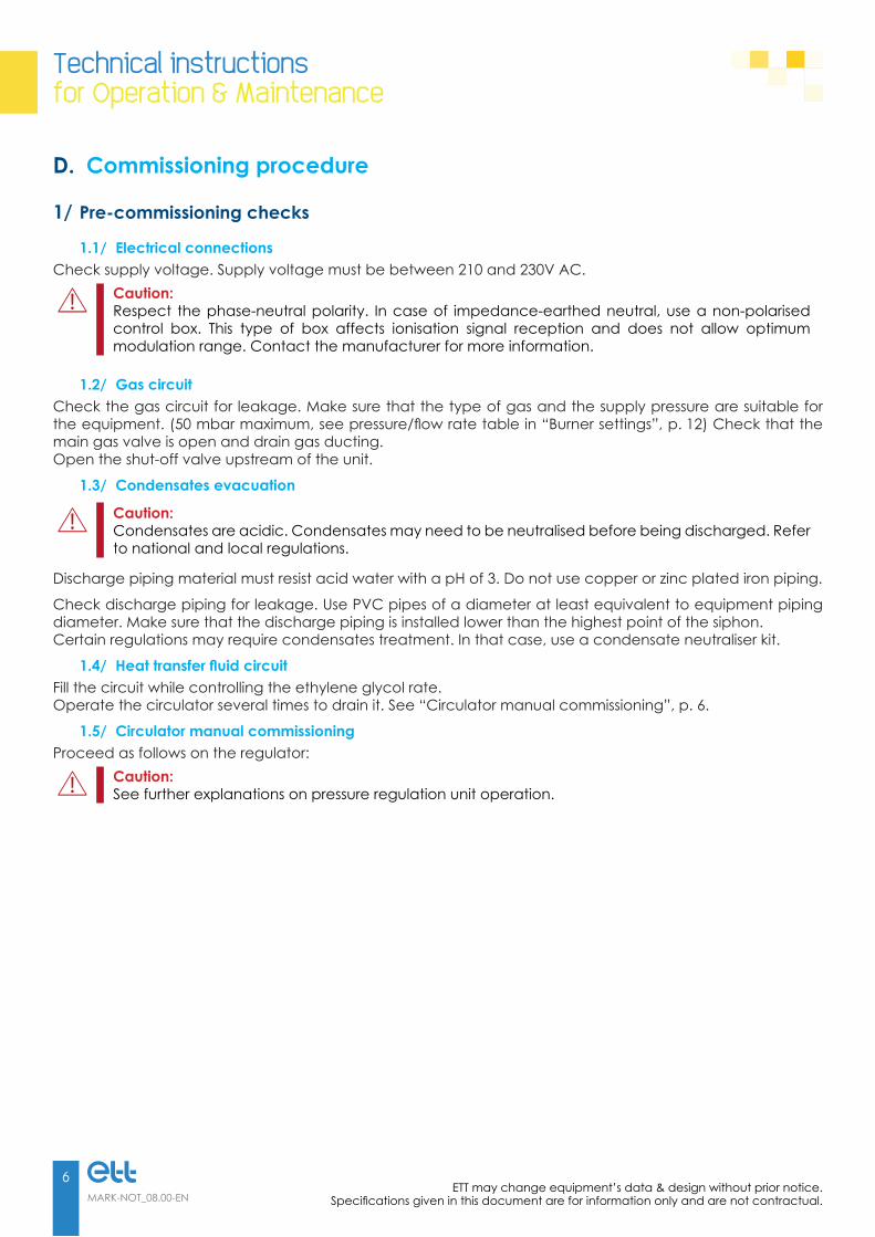
3/ Forcing capacity
4/ Addressing and reprogramming a boiler CTA card
Setpoint: 022 %Returned: 000 %
Setpoint: 050 %Returned: 000 %
Setpoint: 022 %Returned: 000 %
Press , then press several times to reach the line “Setpoint”. Hold
for 5 s. The first line flashes. Hold for 5 s.
Use the key pad to enter the desired capacity and press to confirm. The value will be kept for 5 minutes, while the first line flashes.
Return to the “Setpoint” line and press to return capacity to normal mode.
Boiler 1Data link
Boiler 2Programming
Boiler 2Press reset
Press , then press several times to reach the line “Data link”. Hold
for 5 s.
Use the keypad to enter the number of the boiler you want to reset and press to confirm.
Press reset for the selected boiler, wait for the message “programming OK”, then press to exit.
Technical instructionsfor Use & Maintenance
11
MARK-NOT_08.00-ENETT may change equipment’s data & design without prior notice.Specifications given in this document are for information only and are not contractual.
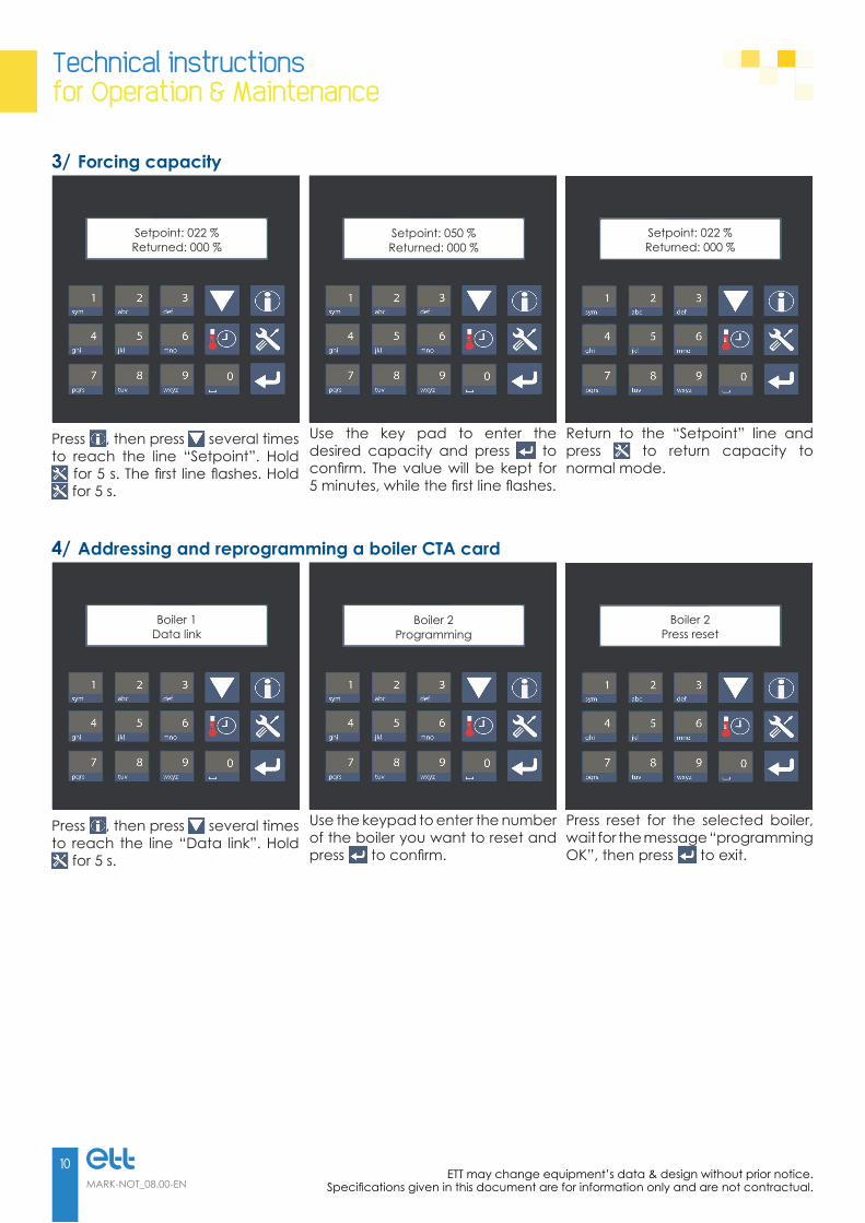
F. Setting the burner
1/ Required tools > 2.5 mm hexagon key (for air-gas ratio setting High flow “4”) > 4.0 mm hexagon key (for air-gas ratio setting Low flow “5”) > Combustion analyser (O2/CO - Smokes temperature) > Gas manometer (max. pressure 50 mbar)
2/ Premix burner control and setting procedure• Calibrate the combustion analyser and place the sensor in the smoke duct.• Check gas supply pressure before start-up, when stopped and in operation (see table).• Start the module:
> Start the boiler in High flow mode (see Setting the burner on the regulator). > Check the oxygen (O2) level after 1 minute of operation. > Use screw 4 to adjust the level according to the table below. Turn the screw clockwise to lower the O2 level, turn counter-clockwise to increase the level. > Switch to Low flow mode (see Setting the burner on the regulator). > Use screw 5 to adjust the level according to the table below. > Turn the screw clockwise to increase the O2 level, turn counter-clockwise to lower the level. > Once low flow is set, exit the setting mode.
1. Burner fan2. Variable venturi3. Gas control valve4. High Flow mode5. Low Flow mode
Technical instructions for Operation & Maintenance
12
MARK-NOT_08.00-ENETT may change equipment’s data & design without prior notice.
Specifications given in this document are for information only and are not contractual.
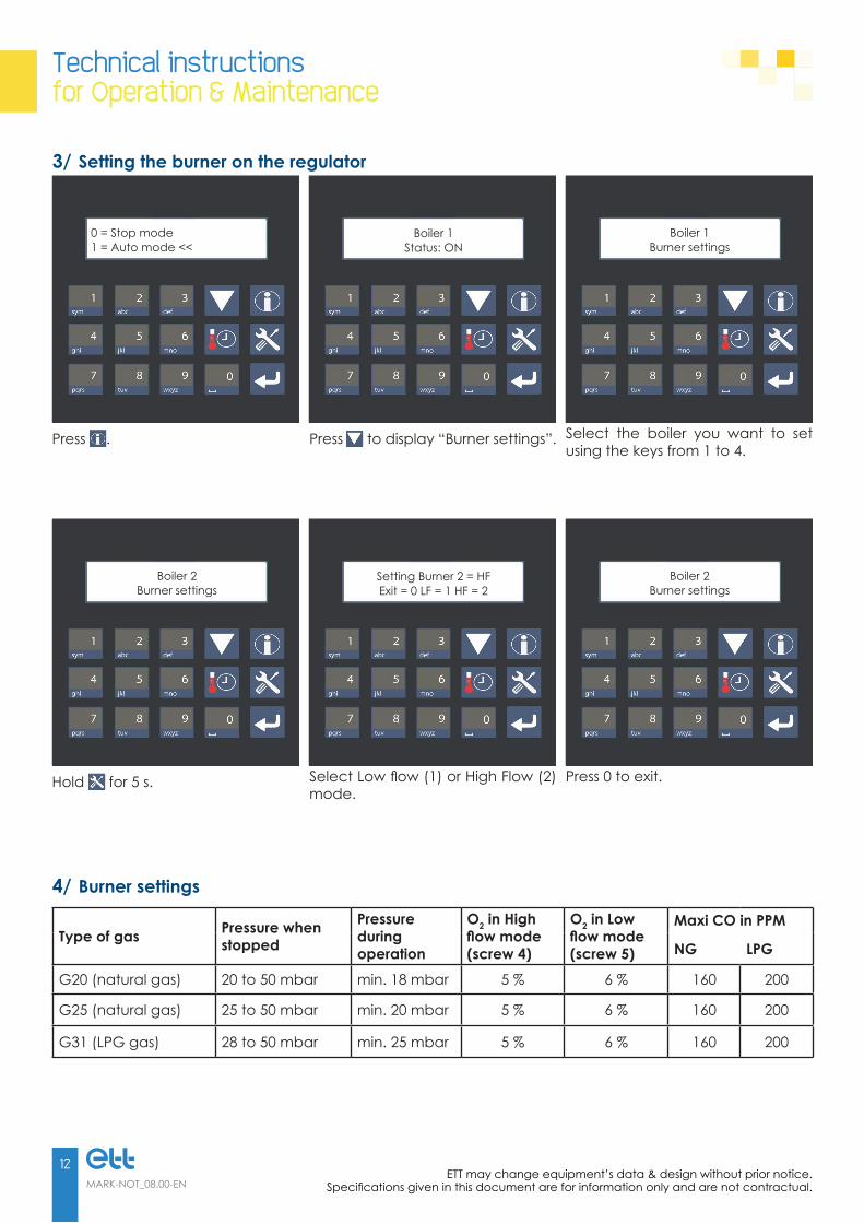
3/ Setting the burner on the regulator
4/ Burner settings
Type of gas Pressure when stopped
Pressure during operation
O2 in High flowmode(screw 4)
O2 in Low flowmode(screw 5)
Maxi CO in PPM
NG LPG
G20 (natural gas) 20 to 50 mbar min. 18 mbar 5 % 6 % 160 200
G25 (natural gas) 25 to 50 mbar min. 20 mbar 5 % 6 % 160 200
G31 (LPG gas) 28 to 50 mbar min. 25 mbar 5 % 6 % 160 200
0 = Stop mode1 = Auto mode <<
Boiler 1Status: ON
Boiler 1Burner settings
Press . Press to display “Burner settings”. Select the boiler you want to set using the keys from 1 to 4.
Boiler 2Burner settings
Setting Burner 2 = HFExit = 0 LF = 1 HF = 2
Boiler 2Burner settings
Hold for 5 s. Select Low flow (1) or High Flow (2) mode.
Press 0 to exit.

Technical instructionsfor Use & Maintenance
13
MARK-NOT_08.00-ENETT may change equipment’s data & design without prior notice.Specifications given in this document are for information only and are not contractual.
G. Operating cycles and boiler safety
The CTA card continuously monitors sensors values. In a fault is detected, the boiler is stopped. To reset the fault, press the rest key on the CTA box of the concerned boiler. The fault and its origin are displayed on the regulator. Only “water pressure” faults must be reset on the regulator. In case of flame fault, the burner will attempt to restart 3 times.
The regulator send the start-up command
Sensors operation control
Fault report Sensor fault Sensors OK
Reset required Boilers water flow rate control
Insufficient water flow rate Water flow rate OK
Burner fan start-up
Burner fan speed control
Burner fan fault Insufficient speed Speed OK
Reset required Electrode ignition and gas solenoid valve opening
Flame control with ionisation probe
Flame fault Ionisation fault Ionisation OK
Reset required Boiler modulation according to settings
Boiler capacity (measured by the water flow and differential T°C between inlet and outlet) is adapted according to the
demand.

Technical instructions for Operation & Maintenance
14
MARK-NOT_08.00-ENETT may change equipment’s data & design without prior notice.
Specifications given in this document are for information only and are not contractual.
H. Recommendations to the user
1/ Safety rules• Do not block or reduce ventilation openings.• Do not block smoke evacuation and fresh air intake.• Do not change the settings made by the qualified professional.• Do not touch hot and/or moving parts of the module.• Do not put any object on the unit or hang anything from it.• Power and gas supplies must be cut before any intervention on the unit.• Do not change the type of gas used, the unit settings, the security or control systems. It may result in
hazardous situations.• Contact the maintenance technician in case of change of gas, gas pressure or supply voltage.• Disconnect power supply if the equipment is not used for an extended period of time.• It is recommended to you consult a professional to restart the equipment.• Repairs and maintenance operations must only be performed by qualified personnel.
2/ Troubleshooting
Problem Solution
Gas smell - Close the external gas valve, cut off the power supply and contact the maintenance technician.
Burner safety lock-out - Reset the burner from the control box. - If the problem persists, contact the maintenance technician.

Technical instructionsfor Use & Maintenance
15
MARK-NOT_08.00-ENETT may change equipment’s data & design without prior notice.Specifications given in this document are for information only and are not contractual.
I. Diagnostics and troubleshooting support
Faults Cause Solution
The equipment does not start.
- Main switch OFF - Green indicator OFF = no power supply - The optimiser reports a communication fault. - The optimiser reports a sensor fault. - The optimiser reports a burner fault. - The optimiser reports a water circuit fault. - Burner fan out of service - Wrong addressing
- Turn the switch ON. - Check power supply. - Check communication cable. - Check the sensor. Replace if necessary. - Reset the burner. - Check water level and pump. - Replace. - Check equipment addressing. - Configure the optimiser.
The burner fan starts several times with no flame.
- No gas - Air in piping - Incorrect air-gas setting - Faulty gas solenoid valve - Ignition electrode not properly installed or faulty - Faulty control box
- Check pressure. - Drain piping. - Set air-gas ratio. - Replace. - Set or replace. - Set or replace.
The burner fan operates at full speed but capacity is not at its maximum.
- Flue too long - Air intake duct or flue blocked - Incorrect burner setting - Return air temperature too high
- Reduce flue length or accept. - Unblock ducts. - Set combustion. - Room temperature too high
The burner is not modulating and the burner fan operates at full speed.
- Incorrect optimiser setting - PWM control cable disconnected - Faulty ventilation fan - Faulty electronic card
- Set. - Check connection. - Replace.
The burner starts, the flame appears and the control box switches to safety lock-out.
- Reversed phase/neutral - Power supply without neutral - Faulty ionisation probe
- Switch phase and neutral on power supply - Use an SNI inspection box. - Replace.
For versions with variable air flow. The air fan does not modulate.
- Speed variation not regulated on optimiser - Speed variation cable disconnected - Faulty motor
- Set the speed on the optimiser. - Check the cable. - Replace.

Technical instructions for Operation & Maintenance
16
MARK-NOT_08.00-ENETT may change equipment’s data & design without prior notice.
Specifications given in this document are for information only and are not contractual.
J. Exploded view
! Caution:Only original parts can guarantee equipment safety.Using non-original parts rules out manufacturer’s liability for any resulting damage.

Technical instructionsfor Use & Maintenance
17
MARK-NOT_08.00-ENETT may change equipment’s data & design without prior notice.Specifications given in this document are for information only and are not contractual.
No. Description Item code
1 Regulator HGGY 903
2 Slave card CTA 1 HGGY 904
3 Cold door with burner HGGY 905
4 Supply card IMT 1 HGGY 906
5 Burner control box HGGY 907
6 Gas control valve HGGY 908
7 Boilers outlet header HGGY 909
8 Safety valve HGGY 910
9 Boilers inlet header HGGY 911
10 Gas header HGGY 912
11 Gas pipe venturi HGGY 913
12 Water pressure sensor HGGY 914
13 Variable venturi HGGY 915
14 Burner fan HGGY 916
15 Condensates evacuation pipe HGGY 917
16 Flow meter HGGY 918
17 Outlet temperature probe HGGY 919
18 Inlet temperature probe HGGY 920
19 Condensing boiler HGGY 921
20 Smoke seal HGGY 922
21 Individual gas hose HGGY 923
22 Boiler temperature probe HGGY 924

www.ett.fr
Reference: MARK-NOT_08.00-EN56 Route de Brest - BP26 - 29830 PLOUDALMEZEAU - FranceTel: +33 (0)2 98 48 14 22 - Fax : +33 (0)2 98 48 09 12Export Contact: +33 (0)2 98 48 00 70 - ETT Services: +33 (0)2 98 48 02 22
Des
ign:
ETT
- D
ocum
ent p
rinte
d by
an
envi
ronm
enta
lly fr
iend
ly p
rinte
r usi
ng v
eget
able
bas
ed in
k on
PEF
C p
aper
cre
ated
from
sus
tain
ably
-man
aged
fore
st.
A different c l imateEnvironmental control solutions
É n e r g i e T r a n s f e r t T h e r m i q u e