
Installa on Instruc ons and Use & Care Guide Residential ...

TechnicalInformation
DAQSTATION CX1000/CX2000Control and Measurement StationInstallation Guidance
TI 04L31C01-01E
TI 04L31C01-01E©Copyright Nov. 20011st Edition Nov. 2001

Blank Page
All Rights Reserved. Copyright © 2001, Yokogawa Electric Corporation TI 04L31C01-01E
i<Toc> Foreword
Nov.06,2001-00
ForewordThis user’s manual provides installation and wiring instructions, as well as safety precautions thatmust be observed when handling or operating the CX1000/CX2000 Control and MeasurementStation.
Notes
• The contents of this manual are subject to change without prior notice.
• Copying or reproduction of all or any part of the contents of this manual without the permis-sion of Yokogawa Electric Corporation is strictly prohibited.
Trademarks
• Microsoft, MS-DOS, Windows, and Windows NT are trademarks or registered trademarks ofMicrosoft Corporation in the United States and/or other countries.
• Adobe and Adobe Acrobat are trademarks of Adobe Systems Incorporated.
• Zip is a trademark or registered trademark of Microsoft Corporation in the United Statesand/or other countries.
• All other company and product names used in this manual are trademarks or registeredtrademarks of their respective companies.
ii
All Rights Reserved. Copyright © 2001, Yokogawa Electric Corporation
<Toc>
TI 04L31C01-01E
Foreword
Nov.06,2001-00
Safety PrecautionsThis is an IEC safety class I instrument (it is equipped with a protective ground terminal), installa-tion category II, and meets the EMC standard EN61326-1 class A for commercial or industrialuse. The general safety precautions listed in this manual must be taken during all phases ofoperation. If the instrument is used in a manner not specified by this manual, the protectivefeatures provided by the instrument may be impaired. Yokogawa Electric Corporation assumes noliability for the customer’s failure to comply with these requirements.
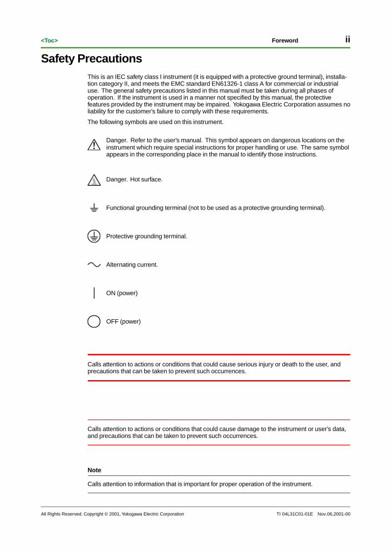
The following symbols are used on this instrument.
Danger. Refer to the user’s manual. This symbol appears on dangerous locations on theinstrument which require special instructions for proper handling or use. The same symbolappears in the corresponding place in the manual to identify those instructions.
Danger. Hot surface.
Functional grounding terminal (not to be used as a protective grounding terminal).
Protective grounding terminal.
Alternating current.
ON (power)
OFF (power)
Calls attention to actions or conditions that could cause serious injury or death to the user, andprecautions that can be taken to prevent such occurrences.
Calls attention to actions or conditions that could cause damage to the instrument or user’s data,and precautions that can be taken to prevent such occurrences.
Note
Calls attention to information that is important for proper operation of the instrument.

All Rights Reserved. Copyright © 2001, Yokogawa Electric Corporation TI 04L31C01-01E
iii<Toc> Foreword
Nov.06,2001-00
Failure to take the following precautions might result in shock, injury, or death of personnel.
• Use the Correct Power Supply
Ensure that the source voltage matches the voltage of the power supply before turning ONthe power.
• Connect the Protective Grounding Terminal
To prevent electric shock, be sure to connect the protective grounding before turning on thepower.
• Do Not Impair the Protective Grounding
Never cut off the internal or external protective grounding wire or disconnect the wiring fromthe protective grounding terminal. Doing so might disable the protective features of theinstrument thereby creating a safety hazard.
• Do Not Operate with Defective Protective Grounding or Fuse
Never operate the instrument if you suspect the protective grounding, fuse, or other protec-tive features might be defective.
• Do Not Operate Near Flammable Materials
Do not operate the instrument in the presence of flammable liquids or vapors. Operation ofthe instrument in such an environment constitutes a safety hazard.
• Do Not Remove Any Covers
Only qualified personnel should remove the cover. Some areas inside the instrument carryhigh voltages.
• Connect to Ground before Making External Connection
Securely connect the protective grounding before connecting to the item under measure-ment or the control unit.
• Do Not Mishandle the Instrument
Operating the instrument in a way not described herein may impair its protective features.

iv
All Rights Reserved. Copyright © 2001, Yokogawa Electric Corporation
<Toc>
TI 04L31C01-01E
Foreword
Nov.06,2001-00
Overview of the CX1000/CX2000The CX1000/CX2000 features “control functions” that allow the user to perform PID control andON/OFF control, and “measurement functions” through which measurement data and controloutput data can be displayed or recorded.
Control Functions
The instrument offers single loop, cascade, or loop control with PV switching, with up to 2 PIDcontrol loops on the CX1000, and up to 6 on the CX2000. Also, by connecting a UT or UP seriescontroller from YOKOGAWA M&C Corporation, you can perform simultaneous control of externalloops (up to 4 loops with the CX1000 or up to 16 with the CX2000). In addition to being able toobserve the control status on a general display such as a controller or faceplate display, and ahybrid screen for a combination of both controller or faceplate displays, and an overview displayallowing observation of all control loops including external loops. The CX1000/CX2000 featuresPID constant autotuning, and manual tuning is available to allow adjustment of such things as thecontrol parameters of the PID constant while confirming the control status.
Measurement Functions
In addition to using measured data for the control functions, a maximum of 20 channels of mea-surement data can be read in and displayed as waveforms, as numerical values, or in bar graphs.Also, both measured data and control data can be copied from the built-in hard disk to a floppydisk, ZIP disk, or ATA flash memory card.
Input/Output Configuration of the CX1000
SSR
R1
RS422/RS485/RS232
• Universal control output: 2 loops Select from current/voltage pulse/relay output• 6 contact inputs for control• Contact output for control 2 relay outputs 4 transistor outputs
5 universal measurement inputs
PC
LAN (Ethernet)
CX1000
Control loop sectionUp to 2 loops
(select 0 or 2 loops)
Ethernet Power supply section
Alarm output section
Measurement input section
CH 6
Control output terminal group(loops 1 and 2: CX1206)
Measurement alarm output(available only with the CX1006)
Control input terminal block
Measurement input terminal blockCH1 to CH6
6 contactinputs
6 universal measurement inputs
AC100 V-AC240/24 VDC (optional)
PLC (YOKOGAWA'S FA-M3 and others)
Controller (maximum 4 loops)
Controlled device
Magnetswitch
6 contactoutputs

All Rights Reserved. Copyright © 2001, Yokogawa Electric Corporation TI 04L31C01-01E
v<Toc> Foreword
Nov.06,2001-00
Input/Output Configuration of the CX2000
SSR
R3
R2
R1
Select from one of the following terminal blocks
PC
CX2000
Ethernet
RS422/RS485/RS232
• Universal control output: 2 loops Select from current/voltage pulse/relay output• 6 contact inputs for control• Contact output for control 2 relay outputs 4 transistor outputs
Control output terminal block 2
(for loops 3 and 4)
Control output terminal block 3
(for loops 5 and 6)
Optional output section
Control input terminal block 1
Measurement input terminal block 1CH1 to CH10
Measurement input terminal block 2CH11 to CH20
Measurement input section
(10 CH/20 CH)
Controlled device
Magnetswitch
Magnetswitch
6 contactinputs
6 contactoutputs
6 contactinputs
6 contactoutputs
6 contactinputs
6 contactoutputs
LAN (Ethernet)
Control loop sectionUp to 6 loops
(select 0, 2, 4, or 6 loops)
Power supply section
Control output terminal block 1
(for loops 1 and 2)
Measurement alarm output (/A6, /A4F options)
Control DIO extension (/CSTI option)
Measurement alarm output + remoteInput (/A6R, /A4FR option)
24 VDC transmitter power supply, 4 (/TPS4 option)
AC100 V_AC240/24 VDC (optional)
PLC (YOKOGAWA'S FA-M3 and others)
Controller (maximum 16 loops)
10 universal measurement inputs
10 universal measurement inputs
10 universal measurement inputs

Blank Page

All Rights Reserved. Copyright © 2001, Yokogawa Electric Corporation TI 04L31C01-01E
Toc-1
Nov.06,2001-00
CONTENTS
TI 04L31C01-01E 1st Edition
DAQSTATION CX1000/CX2000Control and Measurement StationInstallation Guidance
Foreword ............................................................................................................... i
Safety Precautions................................................................................................ii
Overview of the CX1000/CX2000 .........................................................................iv
1. Product Information................................................................................ 1-11.1 Model and Suffix Codes.................................................................................. 1-1
1.2 Names and Uses of Parts ............................................................................... 1-3
2. Installation .............................................................................................. 2-12.1 Dimensions ..................................................................................................... 2-1
2.2 Installation ....................................................................................................... 2-4
2.3 Wiring .............................................................................................................. 2-7
2.4 Connecting a Monitor to the VGA Output Terminal (/D5 Option) ................ 2-19
2.5 Wiring the Transmitter Power Supply Output (/TPS4 Option) ..................... 2-20
2.6 Connecting the Ethernet Interface ............................................................... 2-22
2.7 Serial Interface Specifications ..................................................................... 2-23
2.8 Connecting the Power Supply ...................................................................... 2-30
3. Installation Environment ........................................................................ 3-1
Technical Information Revision Information........................................................ i

Blank Page

All Rights Reserved. Copyright © 2001, Yokogawa Electric Corporation TI 04L31C01-01E
1-1<Toc> 1. Product Information
Nov.06,2001-00
1. Product Information
1.1 Model and Suffix CodesDAQSTATION CX1000
Suffix code
Optioncode Description
-1
-2
-3
-1
-2
-0
-1
-2
/A6
/A6R
/A4F
/A4FR
/CM1
/CM2
/M1
/N2
/P1
/PG1
/PG2
CX1000 internal control loops: 0 loop, measurement channels: 6 ch*1
CX1000 internal control loops: 2 loops, measurement channels: 6 ch
Floppy disk (3.5 inch)
Zip disk (with medium)
ATA flash memory card (with medium)
Ethernet only
RS-232 communications interface
RS-422A/485 communications interface
Japanese
English
Measurement alarm (DO 6) *2
Measurement alarm (DO 6, DI 8 (remote inputs)) *2
Measurement alarm (DO 4, FAIL/memory end output relay) *2
Measurement alarm (DO 4, DI 8 (remote inputs), FAIL/memory end output relay) *2
Green series communication*3
Ladder communication *3
Mathematical function (including report function)
3 legs isolated RTD *4
DC/AC 24 V power supply
Program control (4 program patterns) *5
Program control (30 program patterns) *5
CX1006
CX1206
Displayed language
Option specifications
Externalmemorymedium
Communications interface
*1: If RS-232 or RS-422/485 is specified, /CM1 must also be specified.*2: If the CX1006 is specified, only 1 measurement alarm can be specified.*3: Either RS-232 or RS-422/485 must be specified.
Only one or the other can be selected.*4: For measurement input. All control input is isolated.*5: Only effective for internal loops. One or the other can be selected.
1-2
All Rights Reserved. Copyright © 2001, Yokogawa Electric Corporation
<Toc>
TI 04L31C01-01E
1. Product Information
Nov.06,2001-00
DAQSTATION CX2000
CX2010
CX2020
CX2210
CX2220
CX2410
CX2420
CX2610
CX2620
Displayed language
Option
External memory medium
Communications interface
Suffixcode
Optioncode
-1
-2
-1
-1
/A6
/A6R
/A4F
/A4FR
/CM1
/CM2
/CST1
/D5
/M1
/N2
/P1
/TPS4
/PG1
/PG2
-3
-0
-1
-2
CX2000 internal control loops: 0 loop, measurement channels: 10 ch *1
CX2000 internal control loops: 0 loop, measurement channels: 20 ch *1
CX2000 internal control loops: 2 loops, measurement channels: 10 ch
CX2000 internal control loops: 2 loops, measurement channels: 20 ch
CX2000 internal control loops: 4 loops, measurement channels: 10 ch
CX2000 internal control loops: 4 loops, measurement channels: 20 ch
CX2000 internal control loops: 6 loops, measurement channels: 10 ch
CX2000 internal control loops: 6 loops, measurement channels: 20 ch
Floppy disk (3.5 inch)
Zip disk (with medium)
ATA flash memory card (with medium)
Ethernet only
RS-232 communications interface
RS-422A/485 communications interface
Japanese
English
Measurement alarm (DO 6) *2
Measurement alarm (DO 6, DI 8 (remote inputs) *2
Measurement alarm (DO 4, FAIL/memory end output relay) *2
Measurement alarm (DO 4, DI 8 (remote inputs), FAIL/memory end output relay) *2
Green series communications *3
Ladder communications *3
Control DIO extension (DO 12, DI 12) *2 *3
VGA output
Mathematical function (including report function)
3 legs isolated RTD *5
DC/AC 24 V power supply
24 VDC transmitter power supply (4 loops) *2
Program control (4 program patterns) *6
Program control (30 program patterns) *6
Description
*1: If RS-232 or RS-422/485 is specified, /CM1 must also be specified.*2: Only one can be specified at a time.*3: /CST1 cannot be specified for CX20xx*4: Either RS-232 or RS-422/485 must be specified.
Only one or the other can be selected.*5: For measurement input. All control input is isolated*6: Only effective for internal loops. Only one or the other can be selected.

All Rights Reserved. Copyright © 2001, Yokogawa Electric Corporation TI 04L31C01-01E
1-3<Toc> 1. Product Information
Nov.06,2001-00
1.2 Names and Uses of Parts
Front Panel
START
STOP
ESC MENU1 2 3
DISP/ENTER
4 5 6
7 8
0
9USER FUNC
MENU and FUNC keysIf you press the MENU key then press the FUNC key for about 3 seconds, the basic setting menu is displayed, and you can view the communications functions setting menu.
CX2000
Arrow keysPress these keys to move between the setting items displayed on the screen.
The DISP/ENTER keyPress this key to enter a setting or to close an input box.
ESC keyPress this key to return to the previous screen, or to cancel the current setting changes.
Character/number input keyPress these keys to enter alphanumeric characters for parameters such as the IP address, domain name, or server name.
Soft keysPress these keys to select the menu displayed on the screen.
DISP/ENTER
MENUESCFUNCUSERSTART STOP
CX1000
Liquid crystal display
ESC keyPress this key to return to the previous screen, or to cancel the current setting changes.
Arrow keysPress these keys to move between the setting items displayed on the screen.
The DISP/ENTER keyPress this key to enter a setting or to close an entry box.
MENU and FUNC keysIf you press the MENU key then press the FUNC key for about 3 seconds, the basic setting menu is displayed, and you can view the communications functions setting menu.
Soft keysPress these keys to select the menu displayed on the screen.
Liquid crystal display

1-4
All Rights Reserved. Copyright © 2001, Yokogawa Electric Corporation
<Toc>
TI 04L31C01-01E
1. Product Information
Nov.06,2001-00
Rear Panel
CX1000
CX2000
Measurement alarm terminals CX1006 onlyOptions (/A6, /A6R,/A4F, and /A4FR)/control output terminals/contact input/output terminals
Control output terminals and contact input/output terminals
Ethernet interface connectorEthernet communications connector. Comes standard.
RS-232C interface connector (optional)
Control input terminals
Measurement input terminals
RS-422-A/485 interface terminals(Optional)
Ethernet interface connectorEthernet communications connector Comes standard.
RS-232C interface connector (optional)
Control input terminals
Measurement input terminals
RS-422-A/485 interface terminal(Optional)
Optional(/A6, /A6R, /A4F, /A4FR, /CST1, /TPS4)

All Rights Reserved. Copyright © 2001, Yokogawa Electric Corporation TI 04L31C01-01E
2-1<Toc> 2. Installation
Nov.06,2001-00
2. Installation
2.1 Dimensions
External Dimensions of the CX1000
Panel thickness 2-26
(Dimensions before attaching the mounting bracket)
(Dimensions after attaching the mounting bracket)
136.5
144151.5
23.4 218165.5
+0.40
136.
59.
37.
5+
0.4
0
144
151.
5
Note
• When mounting the instrument in a panel, use two brackets.
• Use one bracket each for the top and bottom or left and right of the instrument.
The dimensional tolerance f or dimensions less than 10 mm is 0.3 mm.

2-2
All Rights Reserved. Copyright © 2001, Yokogawa Electric Corporation
<Toc>
TI 04L31C01-01E
2. Installation
Nov.06,2001-00
Panel Cut-Out Dimensions for the CX1000
Mounting a Single Unit Mounting Top-to-Bottom (Vertically, Maximum 3 Units)
Mounting Side-to-Side (Horizontally)
137 +20 137 +2
0
L +20 (mm)
L+
20
L +20
137
175
Min
imum
175 Minimum2 282
426
570
714
858
1002
1146
1290
1434
(144xn)-6
3
4
5
6
7
8
9
n
10
Number of units
+2
0
137
+2
0

All Rights Reserved. Copyright © 2001, Yokogawa Electric Corporation TI 04L31C01-01E
2-3<Toc> 2. Installation
Nov.06,2001-00
External Dimensions of the CX2000
279.6
108
27.1 220167.5
Panel thickness 2-26
(Dimensions before attaching the mounting bracket)
(Dimensions after attaching the mounting bracket)180
288294.6
50
+10
279.
69.
37.
5
180
108
288
294.
6
+1
0
Note
• When mounting the instrument in a panel, use two brackets.
• Use one bracket each for the top and bottom or left and right of the instrument.
The dimensional tolerance f or dimensions less than 10 mm is 0.3 mm.
Panel Cut-Out Dimensions for the CX2000
361
Min
imum
360 Minimum
281+20
281
+2
0

2-4
All Rights Reserved. Copyright © 2001, Yokogawa Electric Corporation
<Toc>
TI 04L31C01-01E
2. Installation
Nov.06,2001-00
2.2 Installation
Installation Location and Environment
Install the instrument in a location that meets the conditions belo w. For specific inf ormation on theinstallation en vironment, see chapter 3, “Installation En vironment. ”
• Mount in a Panel
The instrument is designed f or panel mounting.
• Place in a Well-Ventilated Location
To prevent o verheating, install the instrument in a well-ventilated location.
• Minimize Mechanical Vibrations
Choose an installation location with minimal mec hanical vibration.
• Install Horizontally
Install the instrument horizontall y (but note that the instrument can be inc lined up to 30degrees bac kwards for panel mounting).
Note
• Condensation may occur if the instrument is moved to another place where both the ambienttemperature and humidity are higher, or if the temperature changes rapidly. In addition, measure-ment errors will result when using thermocouples. Therefore you should allow the instrument toacclimatize for at least one hour before starting operation.
• The lifetime of the LCD may be shortened if the instrument is used in a high-temperature environ-ment over a long period of time. When installing the instrument in a high-temperature environment(greater than 40°C), we recommend the backlight brightness of the LCD be set to a low setting.
Do not install the instrument in an y of the f ollo wing places.
• In direct sunlight or near heat sources
Install the instrument in a place where the temperature fluctuates onl y slightl y from roomtemperature (23 °C). Placing the instrument in direct sunlight or near heat sour ces can ha veadverse effects on it.
• Where an excessive amount of soot, steam, moisture, dust, or corrosive gases arepresent
Soot, steam, moisture , dust, and corr osive gases will ad versely affect the instrument. Avoidsuch locations.
• Near strong magnetic field sources
Do not bring ma gnets or instruments that pr oduce electr omagnetic fields c lose to theinstrument. Operating the instrument near str ong ma gnetic fields can cause err ors in themeasurements.
• Where the angle for viewing the screen is not optimal
Because the instrument uses a TFT color LCD , it is difficult to vie w the displa y from anextreme angle . Install the instrument so that the monitor can be easil y viewed fr om the fr ont.

All Rights Reserved. Copyright © 2001, Yokogawa Electric Corporation TI 04L31C01-01E
2-5<Toc> 2. Installation
Nov.06,2001-00
Installation Instructions
The instrument should be mounted on a steel panel of thic kness 2 mm to 26 mm.
1. Inser t the instrument into the panel fr ont-side-out.
2. Attac h the mounting brac kets that came with the instrument to the panel accor ding to thefigure on the ne xt page.
• Remove the seals co vering the case’ s mounting brac ket holes, then use tw o brac kets tosuppor t the upper and lo wer or right and left sides of the case .
• The proper tor que for tightening the mounting scre ws is 0.8 to 1.2 Nm.
Tightening the scre ws too m uch can def orm the case or dama ge the brac ket.

2-6
All Rights Reserved. Copyright © 2001, Yokogawa Electric Corporation
<Toc>
TI 04L31C01-01E
2. Installation
Nov.06,2001-00
Panel Mounting the CX1000
Panel Mounting the CX2000

All Rights Reserved. Copyright © 2001, Yokogawa Electric Corporation TI 04L31C01-01E
2-7<Toc> 2. Installation
Nov.06,2001-00
2.3 Wiring
Position of the Input/Output Terminals on the CX1000
The rear panel of the CX1206, with 2 contr ol loops and 6 measurement c hannels, is laid out asshown in the figure belo w. On the CX1006, the optional measurement alarm terminals arelocated in the upper b lock.
CX1206: Control output terminals for loops 1 and 2CX1006: For measurement alarms (optional)
Measurement input terminals (CH1 to CH6)
5 analog input terminals for control
Note
For connections for serial communications and Ethernet, see “CX100/CX2000 CommunicationsInterface User’s Manual (IM 04L31A01-17).”
Signal Assignments on the Control and Measurement Input Terminal Blocks
The 5 points contr ol input terminals (measurement input, remote input) and 6 points measure-ment input terminals are assigned as sho wn in the figure belo w. Note that among the 12 columnsof terminals, 1 column is un used so their terminal scre ws are not attac hed.
SNGL
CAS
PVSW
LOOP12 1
PV(RSP)3
(RSP) PV
PV1PV2
LOOP22 1
PV(RSP)
PV
PV1 (RSP)PV2
b
A
B
1
b
A
B
2
b
A
B
3
b
A
B
4
b
A
B
5
b
A
B
6
For single loop controlFor cascade controlFor loop control with PV switching
Control mode settings
PV, PV1, PV2: measurement input, (RSP): remote input (not available for program control), : unused terminals
Arrangement of Terminals on the Control Output Terminal Block
As sho wn in the figure belo w, in one terminal b lock there are 6 contact inputs, 2 relay contactoutputs, and 4 transistor output terminals in ad dition to 2 loops eac h of current/v oltage pulseoutput and rela y contact output f or contr ol. Wire the terminals accor ding to the settings enteredfor your specific application.
LOOP1NONCC
NOC
2NONCC
LOOP2
CTRL OUT
mAPULS
C
LOOP2mAPULS
C C
56
C
34
456
123
LOOP1
CTRL OUT
DIGITAL OUT DIGITAL OUT DIGITAL IN
NOC
1For loops 1 and 2
Current/voltage pulse output for control
Contact input
Relay contact output
Relay contact output for control
C: CommonNO: Normally openedNC: Normally closedmA: Current outputPULS: Voltage pulse output
Transistor output

2-8
All Rights Reserved. Copyright © 2001, Yokogawa Electric Corporation
<Toc>
TI 04L31C01-01E
2. Installation
Nov.06,2001-00
DIGITAL OUT terminals 1-6 are displa yed as the f ollo wing n umber s in the contact (rela y) outputregistration settings.
DO001-DO006 (contr ol output terminal b lock for loops 1 and 2)
DIGITAL IN terminals 1-6 are displa yed as the f ollo wing n umber s in the contact (rela y) outputregistration settings.
DI001-DI006 (contr ol output terminal b lock for loops 1 and 2)
Note
When registering contact (relay) output settings, the relay contact output numbers (DO001, DO002,DO101, DO102, DO201, DO202) are indistinguishable from the other numbers for transistor output.Be aware of this before registering output signals.
Arrangement of the Terminals on the Optional Measurement Alarm Terminal Block (forthe CX1006)
The optional measurement alarm terminal b lock is inc luded if specified at the time of pur chase.The follo wing f our types are a vailab le.
/A6: 6 DO (alarm outputs)
/A6R: 8 DI (remote inputs) + 6 DO (alarm outputs)
/A4F: 4 DO (alarm outputs) + 1 F AIL/memor y end output
/A4FR: 8 DI (remote inputs) + 4 DO (alarm outputs) + 1 F AIL/memor y end output
The terminals on eac h optional measurement alarm terminal b lock are arrang ed as sho wn in thefigure belo w. Wire the terminals accor ding to the settings entered f or your specific application.
ALARM06NC
NO
C
05NC
NO
C
04NC
NO
C
03NC
NO
C
02NC
NO
C
01NC
NO
C
ALARM REMOTE06NC
NO
C
05NC
NO
C
04NC
NO
C
03NC
NO
C
02NC
NO
C
016
7
8
3
4
5
C
1
2
NC
NO
C
Alarm output• /A6 option
Remote input• /A6R option
C: CommonNO: Normally OpenedNC: Normally Closed
Alarm output• /A4F option
Remote input• /A4FR option
C: CommonNO: Normally OpenedNC: Normally Closed
ALARM REMOTE01020304
FAIL
ALARMMEMORY
MEMORY
02 010304FAIL
C
1
2
3
4
5
6
7
8
NC
NO
C
NC
NO
C
NC
NO
C
NC
NO
C
NC
NO
C
NC
NO
C
NC
NO
C
NC
NO
C
NC
NO
C
NC
NO
C
NC
NO
C
NC
NO
C
Memory end outputFAIL output
ALARM terminals 01-06 are sho wn as the f ollo wing n umber s when entering the alarm outputsettings.
I01-I06
REMOTE terminals 1-8 are sho wn simpl y as 1-8 when entering the alarm output settings.

All Rights Reserved. Copyright © 2001, Yokogawa Electric Corporation TI 04L31C01-01E
2-9<Toc> 2. Installation
Nov.06,2001-00
Note
There are no output registration settings for the FAIL and MEMORY terminals. However the MemoryAlarm Time setting (the conditions for memory end output) is not available. Also, FAIL output can beassigned to the DIGITAL OUT terminals on the control output terminal block for loops 1 and 2, and inthis case registration settings are required.
Terminal Cover Labels
A label sho wing the terminal assignments is affix ed to the fr ont and bac k sides of the co vers oneach of the CX1000’ s terminal b locks.
Label on the Front of the Cover
The terminal n umber s used to set up connections (not the n umber s used f or entering settings)are printed on the label of the fr ont side of the co ver as sho wn in the figure belo w.
104
105
106
107
108
109
110
111
112
113
114
115
116
117
118
119
120
121
122
123
124
125
126
127
128
129
130
131
132
133
LOOP2 LOOP1 CAT
101
102
103
For an analog input and measurement input terminal block with 2 control loops.
For a digital output terminal block with 2 control loops.
CAT DIGITAL-INDIGITAL-OUTCTRL-OUTDIGITAL-OUTCTRL-OUT
004
005
006
001
002
003
007
008
009
010
011
012
013
014
015
016
017
019
020
022
023
018
025
026
027
028
029
030
The terminal n umber is a unique , three-digit n umber , with the v alue of the fir st digit indicating theterminal b lock, and the v alue of the second digit indicating the position within the terminal b lock,star ting with 01 in the upper right all the wa y to 36 in the lo wer left. Unused terminals are indi-cated b y a square [ ].
0
1
Label on the Back of the Cover
Codes indicating the input/output signal types are printed on the label on the bac k side of thecover as sho wn in the figure belo w. The diagram is f or a terminal b lock with 2 loops of analoginput f or contr ols, and measurement input. For instructions on the wiring corresponding to eac hsymbol, see pages 2-16 through 2-18.
SNGL
CAS
PVSW
LOOP12 13
LOOP22 1
PV, PV1, PV2: Measurement input, (RSP): Remote Input (not available for program control), : unused terminals
b
A
B
1
b
A
B
2
b
A
B
3
b
A
B
4
b
A
B
5
b
A
B
6
b
A
B
b
A
B
b
A
B
b
A
B
b
A
B

2-10
All Rights Reserved. Copyright © 2001, Yokogawa Electric Corporation
<Toc>
TI 04L31C01-01E
2. Installation
Nov.06,2001-00
Position of the Input/Output Terminals on the CX2000
The rear panel of the CX2620 with 6 contr ol loops, 20 measurement c hannels, and the optionalmeasurement alarm terminal b lock is laid out as sho wn in the figure belo w. The terminals on thespecific instrument y ou or dered ma y diff er from those sho wn here . The optional measurementalarm terminal b lock is installed in the lo wer left position. Depending the specified options, the 24VDC transmitter po wer suppl y output terminal b lock or the contr ol DIO extension terminal b lockmay be installed in this position instead of the optional measurement alarm terminal b lock.
VIDEO OUT(VGA)
L N
10 control analog input terminal block
Measurement input terminal block (CH1 to CH10)
Measurement input terminal block (CH11 to CH20)
Control output terminal block for loops 1 and 2
Control output terminal block for loops 3 and 4
Control output terminal block for loops 5 and 6
Optional terminal block (options /A6, /A6R, /A4F, /A4FR, /CST1, and /TPS4)
Note
For connections for serial communications and Ethernet, see “CX100/CX2000 CommunicationsInterface User’s Manual (IM 04L31A01-17).”
Input/Output Assignments on the Analog Input Terminal Block for Control
This is a 10 points input terminal input, and measurement input (PV) and remote input (RSP) areassigned depending on the settings f or the n umber of used loops and contr ol mode as sho wn inthe figure belo w. Each cell in the figure corresponds to the /b, +/A, and -/B terminals fr om onecolumn. The input terminal assignments c hange if the contr ol mode is s witc hed. Also, among the12 columns of terminals, the 2 columns on the ends of the b lock are un used so their terminalscrews are not attac hed.
LOOP12 1
PV SNGL
CAS
PVSW
(RSP)
(RSP) PV
PV1PV2
LOOP2 LOOP5LOOP62 1
PV1
PV1
PV (RSP)
PV
PV1PV2
LOOP32 1
PV(RSP)
(RSP) PV
PV1PV2
LOOP42 1
PV(RSP)
PV
PV1PV2
For single loop controlFor cascade controlFor loop control with PV switching
• 6 loopsPV, PV1, PV2: Measurement input, (RSP): Remote Input (not available for program control): unused terminals
[Control mode setting]
LOOP4 LOOP3 LOOP2 LOOP12 1 3 2 1 3 2 12 1
PVPV (RSP)(RSP)
(RSP)
(RSP)
PVPV
PV1PV1 PV2PV2
PVPV (RSP)(RSP)
(RSP)
(RSP)
PVPV
PV1PV1 PV2PV2
For single loop controlFor cascade controlFor loop control with PV switching
[Control mode setting]
• 4 loopsPV, PV1, PV2: measurement input, (RSP): remote input (not available for program control): unused terminals
For single loop controlFor cascade controlFor loop control with PV switching
[Control mode setting]
• 2 loopsPV, PV1, PV2: measurement input, (RSP): remote input (not available for program control): unsaid terminals
LOOP22 1 3 2 1
PVPV (RSP)(RSP)
(RSP)
(RSP)
PVPV
PV1PV1 PV2PV2
LOOP1

All Rights Reserved. Copyright © 2001, Yokogawa Electric Corporation TI 04L31C01-01E
2-11<Toc> 2. Installation
Nov.06,2001-00
Arrangement of Terminals on the Control Output Terminal Block
As sho wn in the figure belo w, in one terminal b lock there are 6 contact inputs, 2 relay contactoutputs, and 4 transistor output terminals in ad dition to 2 contr ol loops eac h of current/v oltagepulse output and rela y contact output. Wire the terminals accor ding to the settings entered f oryour specific application.
LOOP1NONCC
NOC
2NONCC
LOOP2
CTRL OUT
mAPULS
C
LOOP2mAPULS
C C
56
C
34
456
123
LOOP1
CTRL OUT
DIGITAL OUT DIGITAL OUT DIGITAL IN
NOC
1
LOOP3NONCC
NOC
2NONCC
LOOP4
CTRL OUT
mAPULS
C
LOOP4mAPULS
C C
56
C
34
456
123
LOOP3
CTRL OUT
DIGITAL IN
NOC
1
LOOP5NONCC
NOC
2NONCC
LOOP6
CTRL OUT
mAPULS
C
LOOP6mAPULS
C C
56
C
34
456
123
LOOP5
CTRL OUT
DIGITAL IN
NOC
1
DIGITAL OUT DIGITAL OUT
DIGITAL OUT DIGITAL OUT
• For loops 1 and 2
• For loops 3 and 4
• For loops 5 and 6
Current/voltage pulse output for control
Contact inputTransistor output
Relay contact output value
Relay contact output
C: CommonNO: Normally openedNC: Normally closedmA: Current outputPULS: Voltage pulse output
DIGITAL OUT terminals 1-6 are displa yed as the f ollo wing n umber s in the contact (rela y) outputregistration settings.
• DO001-DO006 (contact output terminal b lock for loops 1 and 2)
• DO101-DO006 (contact output terminal b lock for loops 3 and 4)
• DO201-DO206 (contact output terminal b lock for loops 5 and 6)
DIGITAL IN terminals 1-6 are displa yed as the f ollo wing n umber s in the contact input registrationsettings
• DI001-DI006 (contr ol input terminal b lock for loops 1 and 2)
• DI101-DI106 (contr ol input terminal b lock for loops 3 and 4)
• DI201-DI206 (contr ol input terminal b lock for loops 5 and 6)
Note
When registering contact (relay) output settings, the relay contact output numbers (DO001, DO002,DO101, DO102, DO201, DO202) are not distinguished from other numbers which are used fortransistor output. Be aware of this before registering output signals.
2-12
All Rights Reserved. Copyright © 2001, Yokogawa Electric Corporation
<Toc>
TI 04L31C01-01E
2. Installation
Nov.06,2001-00
Arrangement of Terminals on the Control DIO Extension Terminal Block
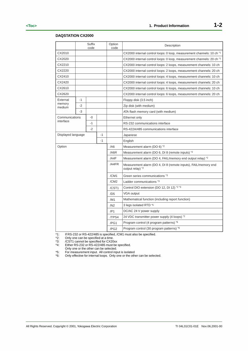
The 12 point contact input and 12 point transistor contact output terminals are arrang ed as sho wnin the figure belo w. Wire the terminals accor ding to the settings entered f or your specific applica-tion.
DIGITAL OUT
1112C
101112
CCC
910C
78C
56
34
12 5
6 3
489
7 12
C
DIGITAL IN
Transistor output Contact input
C: common
DIGITAL OUT terminals 1-12 are displa yed as the f ollo wing n umber s in the contact (rela y) outputregistration settings.
RO001-RO012
DIGITAL IN terminals 1-12 are displa yed as the f ollo wing n umber s in the contact input registrationsettings.
RI001-RI012
Arrangement of Terminals on the Optional Measurement Alarm Terminal Block
The optional measurement alarm terminal b lock is inc luded if specified at the time of pur chase.The follo wing f our types are a vailab le.
/A6: 6 DO (alarm outputs)
/A6R: 8 DI (remote inputs) + 6 DO (alarm output)
/A4F: 4 DO (alarm outputs) + 1 F AIL/memor y end output
/A4FR: 8 DI (remote inputs) + 4 DO (alarm outputs) + 1 F AIL/memor y end output
The terminals on eac h optional measurement alarm terminal b lock are arrang ed as sho wn in thefigure on pa ge 2-8. Wire the terminals accor ding to the settings entered f or your specific applica-tion.
See page 2-8 for the arrangement of the terminals on the optional measurement alarmterminal block.
ALARM terminals 01-06 are sho wn as the f ollo wing n umber s when entering the alarm outputsettings.
I01-I06
REMOTE terminals 1-8 are sho wn simpl y as 1-8 when entering the alarm output settings.
Note
There are no output registration settings for the FAIL and MEMORY terminals. However the MemoryAlarm Time setting (the conditions for memory end output) is not available. Also, FAIL output can beassigned to the DIGITAL OUT terminals on the control output terminal block for loops 1 and 2, and inthis case registration settings are required.

All Rights Reserved. Copyright © 2001, Yokogawa Electric Corporation TI 04L31C01-01E
2-13<Toc> 2. Installation
Nov.06,2001-00
Arrangement of Terminals on the Measurement Input Terminal Block
There are 10 points of measurement input terminals in eac h terminal b lock as sho wn in the figurebelow.
• For CH1-10
• For CH11-20
b
A
B
11
b
A
B
12
b
A
B
13
b
A
B
14
b
A
B
15
b
A
B
16
b
A
B
17
b
A
B
18
b
A
B
19
b
A
B
20
b
A
B
1
b
A
B
2
b
A
B
3
b
A
B
4
b
A
B
5
b
A
B
6
b
A
B
7
b
A
B
8
b
A
B
9
b
A
B
10 Channel number
Channel number
Note
The figure above shows the terminal arrangement in a standard terminal block, and each terminal isshorted across b, but with the 3 wire system isolated RTD option (/N2), each terminal b is not isolated.
Terminal Cover Label
A label sho wing the terminal arrang ement is affix ed to the fr ont and bac k sides of the co vers oneach of the CX2000’ s terminal b locks.
Label on the Front of the Cover
The terminal n umber s used to set up connections (not the n umber s used f or each setting) areprinted on the label on the fr ont side of the co ver as sho wn in the figure belo w.
LOOP5
004
005
006
007
008
009
010
011
012
013
014
015
016
017
018
019
020
021
022
023
024
025
026
027
028
029
030
031
032
033
LOOP1LOOP4 LOOP2LOOP3LOOP6 CAT
• For a terminal block with a 6 loop analog input terminal block for control.
• For control DIO extension terminal block
CAT D I G I T A L I N
604
605
606
601
602
603
607
608
609
610
611
612
619
620
622
623
625
626
628
629
631
632
634
635
D I G I T A L O U T
613
614
615636 633 630 627

2-14
All Rights Reserved. Copyright © 2001, Yokogawa Electric Corporation
<Toc>
TI 04L31C01-01E
2. Installation
The terminal n umber is a unique , three-digit n umber , with the v alue of the fir st digit indicating theterminal b lock, and the v alue of the second digit indicating the position within the terminal b lock,star ting with 01 in the upper right all the wa y to 36 in the lo wer left. Unused terminals are indi-cated b y a square [ ].
VIDEO OUT(VGA)
L N
0
1
2
3
4
5
6
Label on the Back of the Cover
Codes indicating the input/output signal types are printed on the label on the bac k side of thecover as sho wn in the figure belo w. The diagram is f or a terminal b lock with 6 loops of analoginput terminals f or contr ol. For instructions on the wiring corresponding to eac h symbol, seepages 2-16 through 2-18.
CATLOOP 1LOOP 2 LOOP 521 12 1
LOOP 3LOOP 62 1
LOOP 42 1 1
b
A
B
b
A
B
b
A
B
b
A
B
b
A
B
b
A
B
b
A
B
b
A
B
b
A
B
b
A
B
Nov.06,2001-00

All Rights Reserved. Copyright © 2001, Yokogawa Electric Corporation TI 04L31C01-01E
2-15<Toc> 2. Installation
General Precautions When Wiring Input/Output Signals
• To prevent electric shoc k when connecting wires, ensure the main po wer suppl y is turnedOFF.
• If a voltage of more than 30 VAC or 60 VDC is to be applied, use ring-tongue crimp-on lugswith insulation slee ves on all the output terminals to pre vent the wires fr om slipping outwhen the scre ws become loose . Furthermore , use doub le-insulated wires (dielectricstrength of 2300 VAC or more) f or the signal wires on whic h a voltage of more than 30 VACor 60 VDC is to be applied. For all other wires, use basic insulated wires (dielectric strengthof 1350 VAC). To prevent electric shoc k, attach the terminal co ver after wiring and makesure not to touc h the terminals.
• If str ong tension is applied to the input/output signal cab le, the terminals and/or the cab lecan be dama ged. In order to pre vent tension fr om being applied directl y on the terminals,fasten all wired cab les to the rear of the mounting panel.
• Do not appl y a voltage to any of the input terminals e xceeding the le vels belo w. This candamage the instrument.
• Maximum input v oltage
Voltage rang e of 2 VDC or less or thermocouples: 10 VDC
Voltage rang e between 6 and 50 VDC: 60 VDC
• Maximum common mode noise v oltage
250 VACrms (50/60Hz)
• The instrument is an installation categor y II product.
It is recommended that crimp-on lugs (designed for 4 mm screws) with insulationsleeves be used on the input/output signal wires.
For 4 mm screw
Take measures to prevent noise from entering the measurement circuit.
• Move the measurement cir cuit a way from the po wer cab le (power cir cuit) and gr ound cab le.
• The item being measured should not g enerate noise . However, if this is una voidab le, isolatethe measurement cir cuit fr om the item. Also, ground the item being measured.
• Shielded wires should be used to minimiz e noise caused b y electr ostatic induction. Connectthe shield to the gr ound terminal of the instrument as necessar y (make sure y ou are notgrounding at tw o points).
• To minimiz e noise caused b y electr omagnetic induction, twist the measurement cir cuit wiresat shor t, equal inter vals.
• Make sure to ear th gr ound the pr otective gr ound terminal thr ough minim um resistance (lessthan 100Ω).
Nov.06,2001-00
2-16
All Rights Reserved. Copyright © 2001, Yokogawa Electric Corporation
<Toc>
TI 04L31C01-01E
2. Installation
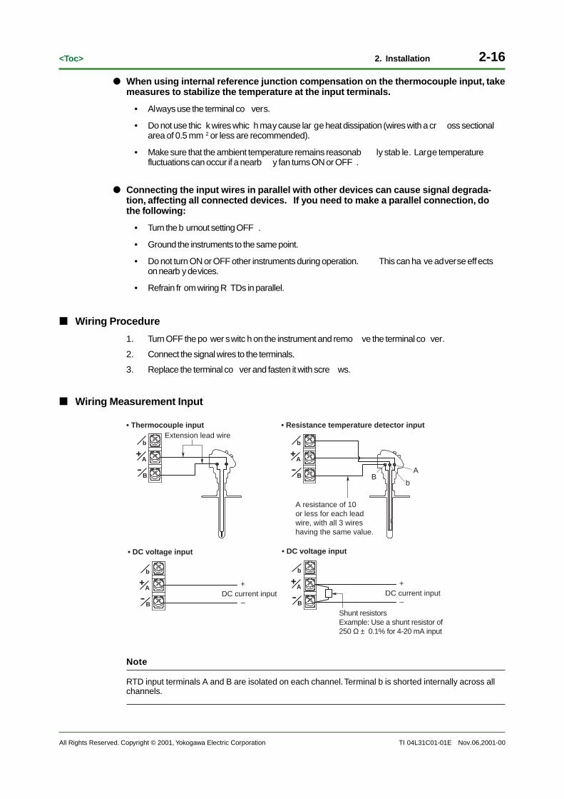
When using internal reference junction compensation on the thermocouple input, takemeasures to stabilize the temperature at the input terminals.
• Always use the terminal co vers.
• Do not use thic k wires whic h may cause lar ge heat dissipation (wires with a cr oss sectionalarea of 0.5 mm 2 or less are recommended).
• Make sure that the ambient temperature remains reasonab ly stab le. Large temperaturefluctuations can occur if a nearb y fan turns ON or OFF .
Connecting the input wires in parallel with other devices can cause signal degrada-tion, affecting all connected devices. If you need to make a parallel connection, dothe following:
• Turn the b urnout setting OFF .
• Ground the instruments to the same point.
• Do not turn ON or OFF other instruments during operation. This can ha ve adverse effectson nearb y devices.
• Refrain fr om wiring R TDs in parallel.
Wiring Procedure
1. Turn OFF the po wer switc h on the instrument and remo ve the terminal co ver.
2. Connect the signal wires to the terminals.
3. Replace the terminal co ver and fasten it with scre ws.
Wiring Measurement Input
DC current input
• Thermocouple input
• DC voltage input
• Resistance temperature detector input
• DC voltage input
DC current input
Shunt resistorsExample: Use a shunt resistor of 250 Ω ± 0.1% for 4-20 mA input
A resistance of 10 or less for each lead wire, with all 3 wires having the same value.
A
bB
Extension lead wire
b
A
B
b
A
B
b
A
B
b
A
B
+
–
+
–
Note
RTD input terminals A and B are isolated on each channel. Terminal b is shorted internally across allchannels.
Nov.06,2001-00

All Rights Reserved. Copyright © 2001, Yokogawa Electric Corporation TI 04L31C01-01E
2-17<Toc> 2. Installation
Wiring the Contact input (DIGITAL IN/REMOTE)
Control output terminals (DIGITAL IN)
• Relay contact input
2
14
6 3
5
C
1
2
3
4
5
6C
• Transistor input
Control DIO extension terminals (DIGITAL IN)
• Relay contact input
9
811
13 10
12
C
6
5
7
2
1
3
C
C
• Transistor input7
8
9
10
11
12
1
2
3
4
5
6C
C
C
Alarm terminals control remote (REMOTE)
C
1
2
3
4
5
6
7
8
• Transistor input• Relay contact input
C
1
2
3
4
5
6
7
8
Relay Contact Input/Transistor Input Specifications
Input Signal: Voltage-free (dr y) contact, open-collector (TTL or transistor)
Input Conditions: 0.5 V or less (30 mADC) when ON, 0.25 mA or less current leaka ge when OFF.
Input Format: Photocoupler isolation (common)
Withstanding Voltage: 500 VDC, 1 min. (between input terminal and ear th)
Nov.06,2001-00

2-18
All Rights Reserved. Copyright © 2001, Yokogawa Electric Corporation
<Toc>
TI 04L31C01-01E
2. Installation
Wiring the Control Output (LOOPS 1-6)
C
mA
4-20 mADC or 0-20 mADC
• Voltage pulse output• Current output
• Relay contact output
C
NO
NC
C
PULS
250 VAC, 3 A or 30 VDC, 3 A (resistance load)
Voltage pulse (12 V)
(when energized)
–
+
+
–
Current Output Specifications
Output Signal: 4-20 mADC or 0-20 mADC
Load Resistance: 600 Ω or more
Voltage Pulse Output Specifications
Output Signal: ON voltage = 12 VDC
Load Resistance: 600 Ω or more
Relay Contact Output Specifications
Output Signal: NC, NO, COM
Contact Rating: 250 VAC (50/60 Hz)/3 A or 30 VDC/3 A (resistance load)
Wiring the Contact Output (DIGITAL OUT)
• Relay contact output from the control output terminal block
C
NC250 VAC, 1 A or 30 VDC, 1 A (resistance load)
• Transistor output from the control output terminal block
C
4
3
2
1
24VDC/50mA
• Transistor output on the control DIO extension terminal block
4
3
2
1
24VDC/50mA6
5
CC
12
11
Relay Output Specifications
Output Format: Relay transf er contact
Contact Rating: 250 VAC (50/60 Hz)/1 A or 30 VDC/1 A (resistance load)
Transistor Output Specifications
Output Format: Open collector output
Contact Rating: 24 VDC/50 mA
Nov.06,2001-00

All Rights Reserved. Copyright © 2001, Yokogawa Electric Corporation TI 04L31C01-01E
2-19<Toc> 2. Installation
2.4 Connecting a Monitor to the VGA Output Terminal (/D5 Option)
• Before connecting the monitor to the instrument, be sure to turn OFF the po wer to bothmonitor and instrument.
• Never shor t the VIDEO OUT terminal or appl y an external v oltage to it. Doing so ma ydamage the instrument.
Location of the VGA Output Terminal
The VGA output terminal is the D-Sub connector on the upper left of the CX2000’ s rear panel, andis marked VIDEO OUT(VGA).
!VIDEO OUT(VGA)
Functions and Specifications of the VGA Output Terminal
The instrument’ s screen can be displa yed on a monitor via RGB output. Only a VGA monitor or amulti-sync hronous monitor whic h is capab le of displa ying VGA can be used.
Pin Assignments and Specifications of the VGA Output Terminal
6
11
15
15
10
D-Sub 15 pin receptacle
Pin No. Signal Name Specification
1 Red 0.7 Vp-p2 Green 0.7 Vp-p 3 Blue 0.7 Vp-p 4 -5 -6 GND7 GND8 GND9 -10 GND11 -12 -13 Horizontal synchronous signal Approx. 31.5 kHz, TTL negative14 Vertical synchronous signal Approx. 60 Hz, TTL negative15 -
Connecting the Monitor
1. Turn OFF the po wer both the monitor and the instrument.
2. Connect the monitor to the instrument using an analog RGB cab le.
3. Turn ON both the monitor and the instrument. The instrument’ s screen is displa yed in themonitor .
Note
• When the power to the instrument is ON, the video signal is always output from the VGA outputterminal.
• The picture on the monitor may become unstable if the instrument or other equipment is broughttoo close to the monitor.
• Some monitors may display a picture with the sides cut off.
Nov.06,2001-00
2-20
All Rights Reserved. Copyright © 2001, Yokogawa Electric Corporation
<Toc>
TI 04L31C01-01E
2. Installation
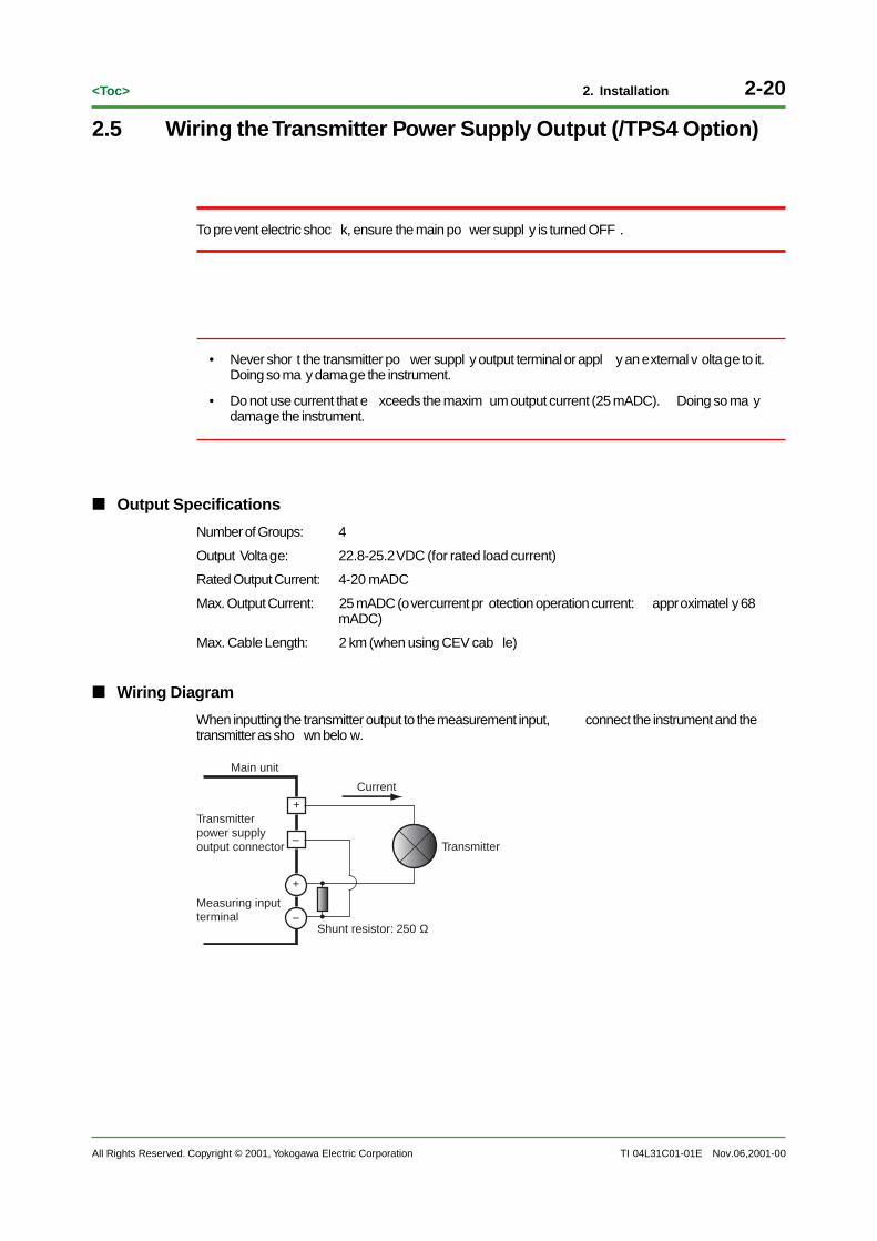
2.5 Wiring the Transmitter Power Supply Output (/TPS4 Option)
To prevent electric shoc k, ensure the main po wer suppl y is turned OFF .
• Never shor t the transmitter po wer suppl y output terminal or appl y an external v oltage to it.Doing so ma y damage the instrument.
• Do not use current that e xceeds the maxim um output current (25 mADC). Doing so ma ydamage the instrument.
Output Specifications
Number of Groups: 4
Output Voltage: 22.8-25.2 VDC (for rated load current)
Rated Output Current: 4-20 mADC
Max. Output Current: 25 mADC (overcurrent pr otection operation current: approximatel y 68mADC)
Max. Cable Length: 2 km (when using CEV cab le)
Wiring Diagram
When inputting the transmitter output to the measurement input, connect the instrument and thetransmitter as sho wn belo w.
Transmitter
Current
Main unit
Transmitter power supplyoutput connector
Measuring input terminal
Shunt resistor: 250 Ω
+
+
–
–
Nov.06,2001-00
All Rights Reserved. Copyright © 2001, Yokogawa Electric Corporation TI 04L31C01-01E
2-21<Toc> 2. Installation
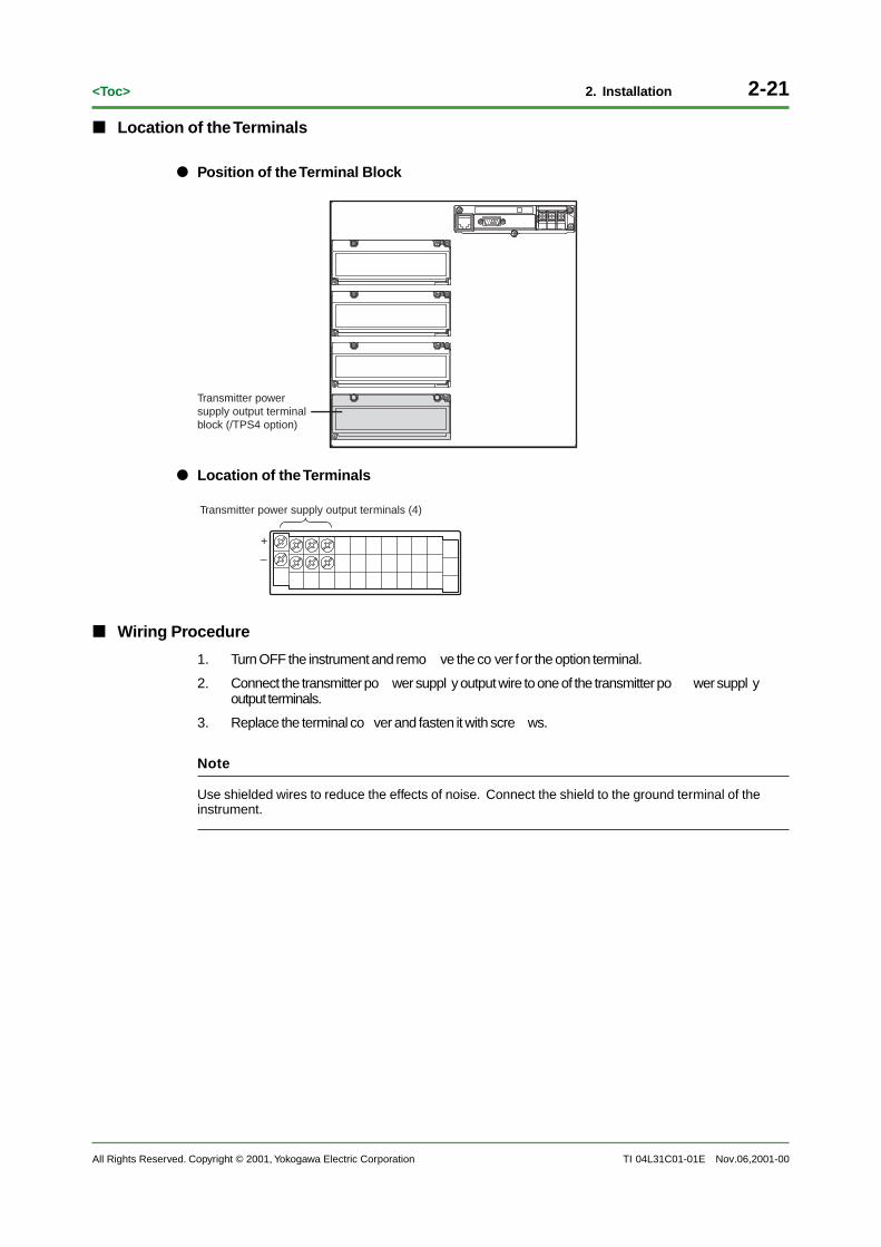
Location of the Terminals
Position of the Terminal Block
Transmitter power supply output terminal block (/TPS4 option)
Location of the Terminals
Transmitter power supply output terminals (4)
+
–
Wiring Procedure
1. Turn OFF the instrument and remo ve the co ver for the option terminal.
2. Connect the transmitter po wer suppl y output wire to one of the transmitter po wer suppl youtput terminals.
3. Replace the terminal co ver and fasten it with scre ws.
Note
Use shielded wires to reduce the effects of noise. Connect the shield to the ground terminal of theinstrument.
Nov.06,2001-00

2-22
All Rights Reserved. Copyright © 2001, Yokogawa Electric Corporation
<Toc>
TI 04L31C01-01E
2. Installation
2.6 Connecting the Ethernet Interface
Connecting the Instrument to a PC via Hub
Connect the instrument and the PC via a HUB as sho wn in the f ollo wing figure .
PC
Ethernet card
Hub
10BASE-T straight cable
10BASE-T straight cable
Ethernet interface connector
Ethernet interface connector
CX
CX
(connect multiple transmitters using a hub)
Within 100 m
Connecting the Instrument to a PC via Network
The figure belo w illustrates an e xample in whic h the instrument and a PC are connected to a pre-existing netw ork. When connecting the instrument or the PC to a netw ork, such things as thetransf er rate and connector type m ust be matc hed. For details, consult y our system or netw orkadministrator .
PC
Ethernet card
10BASE-T straight cable
Pre-existing network
Ethernet interface connector
CX
10BASE-T compatible converter (such as a hub or router)
Within 100 m
Note
• Depending on the reliability of the network or the volume of network traffic, all the transferred datamay not be retrieved by the PC.
• Communication performance deteriorates if multiple PCs access the recorder simultaneously.
Basic Specifications
Electrical, mechanical Conforms to IEEE 802.3 (Ethernet frames conform to the DIX specifications.)
Transmission medium type 10BASE-T
Nov.06,2001-00

All Rights Reserved. Copyright © 2001, Yokogawa Electric Corporation TI 04L31C01-01E
2-23<Toc> 2. Installation
2.7 Serial Interface SpecificationsThe specifications f or the tw o types of serial interfaces (RS-232 and RS-422-A/485) on theinstrument are given belo w.
RS-232 Interface Specifications
Connector type D-Sub 9 pin plug
Electrical, mechanical Complies with EIA-574 Standard (EIA-232 (RS-232) Standard for 9 pin)
Connection Point-to-point
Communication Half-duplex
Synchronization Start-stop synchronization
Baud Rate Select from 1200, 2400, 4800, 9600, 19200, or 38400 bps
Start bit 1 bit (fixed)
Data length Select 7 or 8 bits (Select 8 bits when outputting data in binary format.)
Parity Odd, Even, None
Stop bit 1 bit (fixed)
Hardware handshaking Select whether to fix the RS and CS signals to TRUE or to use the control wire.
Software handshaking Select whether to use the X-ON and X-OFF signals to control the transmitted data only orboth the transmitted and received data.X-ON (ASCII 11H), X-OFF (ASCII 13H)
Receive buffer length 2047 bytes
RS-422-A/485 Interface Specifications
Terminal block type 6 point, terminal block, terminal screws: ISO M4/nominal length 6 mm
Electrical, mechanical Conforms to EIA-422-A (RS-422-A) and EIA-485 (RS-485) standards
Connection Multidrop Four-wire type 1:32 Two-wire type 1:31
Communication Half-duplex
Synchronization Start-stop synchronization
Baud Rate Select from 1200, 2400, 4800, 9600, 19200, or 38400 bps
Start bit 1 bit (fixed)
Data length Select 7 or 8 bits
Parity Odd, Even, None
Stop bit 1 bit (fixed)
Receive buffer length 2047 bytes
Escape sequence Open, close
Electric characteristics FG, SG, SDB, SDA, RDB, RDA (six points)SG, SDB, SDA, RDB, and RDA terminals andthe internal circuit of the instrument is functionally isolated.FG terminal is the frame ground.
Communication distance Up to 1.2 km
Terminator External: recommended resistance 120 Ω, 1/2 W
Nov.06,2001-00
2-24
All Rights Reserved. Copyright © 2001, Yokogawa Electric Corporation
<Toc>
TI 04L31C01-01E
2. Installation
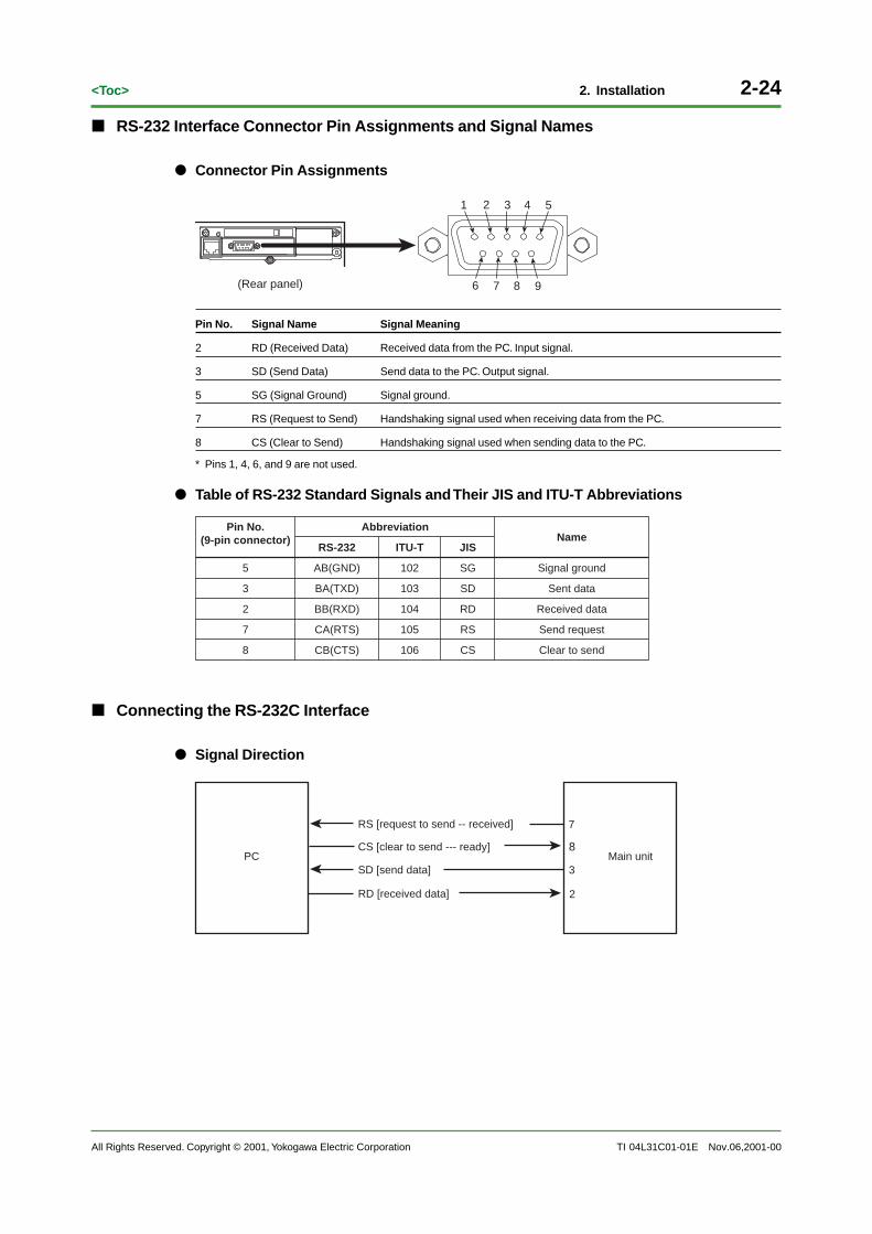
RS-232 Interface Connector Pin Assignments and Signal Names
Connector Pin Assignments
2 1 3 4 5
6 7 98(Rear panel)
Pin No. Signal Name Signal Meaning
2 RD (Received Data) Received data from the PC. Input signal.
3 SD (Send Data) Send data to the PC. Output signal.
5 SG (Signal Ground) Signal ground.
7 RS (Request to Send) Handshaking signal used when receiving data from the PC.
8 CS (Clear to Send) Handshaking signal used when sending data to the PC.
* Pins 1, 4, 6, and 9 are not used.
Table of RS-232 Standard Signals and Their JIS and ITU-T Abbreviations
5
Pin No.(9-pin connector)
8
7
2
3
AB(GND)
RS-232
Abbreviation
CB(CTS)
CA(RTS)
BB(RXD)
BA(TXD)
102
ITU-T
106
105
104
103
SG
JIS
CS
RS
RD
SD
Signal ground
Name
Clear to send
Send request
Received data
Sent data
Connecting the RS-232C Interface
Signal Direction
PC Main unit
RS [request to send -- received]
SD [send data]
RD [received data] 2
3
8
7
CS [clear to send --- ready]
Nov.06,2001-00

All Rights Reserved. Copyright © 2001, Yokogawa Electric Corporation TI 04L31C01-01E
2-25<Toc> 2. Installation
Connection Example
SDRDRSCSSG
SDRDRS
SG
• OFF-OFF/XON-XONPC Main unit
SDRDRSCSSG
SDRDRS
SG
• XON-RS(XON-RTS)PC Main unit
SDRDRSCSSG
SDRDRS
SG
• CS-RS(CTS-RTS)PC Main unit
CS
CS
CS
2 3
8 7
5
2 3
8 7
5
2 3
8 7
5
It is not necessary to connect RS on the PC side and CS on the main unit side for control, but in order to maintain reversability of the signals we recommend you wire it as shown.
RS-232 Interface Handshaking Method
When using the RS-232 interface f or transf erring data, it is necessar y for equipment on both sidesto agree on a set of rules to ensure the pr oper transf er of data. That set of rules is called hand-shaking. Because there are man y handshaking methods that can be used between the instru-ment and the PC, you must make sure that the same method is c hosen f or both.
You can c hoose an y of the f our methods sho wn in the f ollo wing tab le.
Table of Handshaking Methods ( = Function Available)
Handshaking
Data sending control (when sending data to the PC)
Software handshake
No handshake
Sending stops when X-off received, and resumes when X-on is received.
Sending stops when CB(CTS) is False,and resumes when CB is True.
Hardware handshake
OFF-OFF
XON-XON
XON-RS
CS-RS
Data receiving control (when sending data to the PC )
No handshake
Software handshake
Hardware handshake
Sends the X-OFFcommand when the receive buffer is 3/4 full, and the X-ON command when
CA(RTS) is set to False when the receive buffer is 3/4 full, and is set to True when the buffer is 1/4 full.
OFF-OFF
• Data sending control
There is no handshaking between the instrument and the PC. The X-OFF and X-ON signalsare treated as data, and the CS signal is ignored.
• Data receiving control
There is no handshaking between the instrument and the PC. After the instrument’ s receivebuffer becomes FULL, excess data is discar ded.
The RS signal is fix ed to True.
Nov.06,2001-00

2-26
All Rights Reserved. Copyright © 2001, Yokogawa Electric Corporation
<Toc>
TI 04L31C01-01E
2. Installation
RS-422-A/485 Interface Terminal Assignments and Signal Names
(Rear Panel) FG SG SDB SDA RDB RDA
FG (Frame Ground) Case ground of the instrument.
SG (Signal Ground) Signal ground.
SDB (Send Data B) Send data B (+).
SDA (Send Data A) Send data A (–).
RDB (Received Data B) Received data B (+).
RDA (Received Data A) Received data A (–).
Connecting the RS-422-A/485 Interface
Cable
There are tw o types of cab les availab le, the four-wire cab le and the tw o-wire cab le (used onl y forthe Modb us pr otocol). The cable should meet the f ollo wing specifications.
Cable Twisted-pair cable3 pairs 24 AWG or more (four-wire), 2 pair 24AWG or more (two- wire)
Characteristic impedance 100 Ω
Capacitance 50 pF/m
Cable length Up to 1.2 km*
* The transmission distance of the RS-422-A/485 interface is not the straight-line distance, but rather the total length of the (twisted-pair shielded) cable.
Cable Connection Procedure
As sho wn in the figure belo w, attach a crimp-style terminal with an isolating slee ve for 4-mmscrews to the end of the cab le. Keep the section that is e xposed fr om the shielded cab le to 5 cmor less.
FG SG SDB SDA RDB RDA
Shield potential
2-wire system
Shield
FG SG SDB SDA RDB RDA
Shield potential
4-wire system
Shield
Note
• As shown on the next page, connect the RD pin to the SD(TD) pin on the PC (converter) side andthe SD pin to the RD pin on the PC side.
• The two-wire system can be used only when using the Modbus protocol.
Nov.06,2001-00

All Rights Reserved. Copyright © 2001, Yokogawa Electric Corporation TI 04L31C01-01E
2-27<Toc> 2. Installation
An Example of a Connection to a Host Computer
The instrument can be connected to a host computer that has an RS-232, RS-422-A, or RS-485por t.
• For RS-232, use the con verter.
• For recommended con verters, see page 2-29, “• Serial Interface Con verter.”
• The two-wire system can be used onl y when using the Modb us pr otocol.
Four-Wire System
In general, the instrument and the host computer are connected using a f our-wire cab le. For thefour-wire system, the transmission and reception lines m ust be cr ossed.
Termination resistor (external) 120 Ω, of 1/2 W or more
#1
Do not connect a termination resistor to #1-#n-1.
Main unit's RS-422-A/485
terminal
#2 #n(#n≤32)
Termination resistor (external)
Host PC
SG
RDB( + )
RDA( – )
SDB( + )
SDA( – )
FG
SG
RD B
RD A
SD B
SD A
(SG)
(RD B)
(RD A)
(SDB)
(SDA)
FG
SG
RD B
RD A
SD B
SD A
(SG)
(RD B)
(RD A)
(SDB)
(SDA)
FG
SG
RD B
RD A
SD B
SD A
(SG)
(RD B)
(RD A)
(SDB)
(SDA)
(The follo wing dia gram illustrates a case in whic h the host computer’ s interface is RS-232)
Termination resistor (external) 120 Ω, of 1/2 W or more
#1
Do not connect a termination resistor to #1-#n-1.
Main unit's RS-422-A/485
terminal
#2 #n(#n32)
Termination resistor (external)
SHIELD
RD( + )
RD( – )
TD( + )
TD( – )
FG
SG
RD B
RD A
SD B
SD A
Host PC
Converter
(SG)
(RD B)
(RD A)
(SDB)
(SDA)
FG
SG
RD B
RD A
SD B
SD A
(SG)
(RD B)
(RD A)
(SDB)
(SDA)
FG
SG
RD B
RD A
SD B
SD A
(SG)
(RD B)
(RD A)
(SDB)
(SDA)
RS-232
Nov.06,2001-00
2-28
All Rights Reserved. Copyright © 2001, Yokogawa Electric Corporation
<Toc>
TI 04L31C01-01E
2. Installation
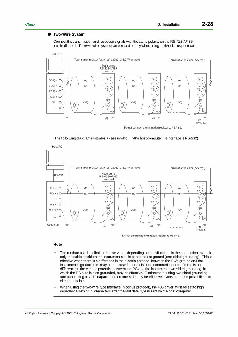
Two-Wire System
Connect the transmission and reception signals with the same polarity on the RS-422-A/485terminal b lock. The two-wire system can be used onl y when using the Modb us pr otocol.
SG
RDB( + )
RDA( – )
SDB( + )
SDA( – )
FG
SG
RD B
RD A
SD B
SD A
(SG)
(B)
(A)
(B)
(A)
FG
SG
RD B
RD A
SD B
SD A
(SG)
FG
SG
RD B
RD A
SD B
SD A
(SG)
(B)
(A)
Termination resistor (external) 120 Ω, of 1/2 W or more
#1
Do not connect a termination resistor to #1-#n-1.
Main unit's RS-422-A/485
terminal
#2 #n(#n31)
Termination resistor (external)
Host PC
(The follo wing dia gram illustrates a case in whic h the host computer’ s interface is RS-232)
FG
SG
RD B
RD A
SD B
SD A
(SG)
(B)
(A)
(B)
(A)
FG
SG
RD B
RD A
SD B
SD A
(SG)
FG
SG
RD B
RD A
SD B
SD A
(SG)
(B)
(A)
SHIELD
TD( + )
TD( - )
RD( + )
RD( - )
RS-232
Termination resistor (external) 120 Ω, of 1/2 W or more
#1
Do not connect a termination resistor to #1-#n-1.
Main unit's RS-422-A/485
terminal
#2 #n(#n31)
Termination resistor (external)
Host PC
Converter
Note
• The method used to eliminate noise varies depending on the situation. In the connection example,only the cable shield on the instrument side is connected to ground (one-sided grounding). This iseffective when there is a difference in the electric potential between the PC’s ground and theinstrument’s ground. This may be the case for long distance communications. If there is nodifference in the electric potential between the PC and the instrument, two-sided grounding, inwhich the PC side is also grounded, may be effective. Furthermore, using two-sided groundingand connecting a serial capacitance on one-side may be effective. Consider these possibilities toeliminate noise.
• When using the two-wire type interface (Modbus protocol), the 485 driver must be set to highimpedance within 3.5 characters after the last data byte is sent by the host computer.
Nov.06,2001-00

All Rights Reserved. Copyright © 2001, Yokogawa Electric Corporation TI 04L31C01-01E
2-29<Toc> 2. Installation
Nov.06,2001-00
Serial Interface Converter
Recommended converter:
MODEL RC-57 by RA SYSTEMS CORP., or Z-101HE by Sharp
Some con verters not recommended b y YOKOGAWA have FG and SG pins that are not isolated.When using suc h a con verter, do not connect an ything to the FG and SG pins as sho wn in thediagram on the pre vious pa ge. This can g enerate a potential diff erence , especiall y for longdistance comm unications, and can dama ge the instrument or cause comm unication abnormali-ties. For con verters that do not ha ve the SG pin, they can be used without using the signalground. For details, see the man ual that came with the con verter.
On some non-recommended con verters, the signal polarity ma y be reversed (A/B or +/_ indica-tion). In this case , reverse the connection.
For a tw o-wire system, the host computer m ust contr ol the transmission driver of the con verter inorder to pre vent collisions of transmitted and received data. When using the recommendedconverter, the driver is contr olled using the RS (R TS) signal on the RS-232.
When Using Any Instrument That Supports Only the RS-422-A Interface
When using the f our-wire type interface , up to 32 instruments can be connected to a single hostcomputer . However, this ma y not be true if the instrument that suppor t onl y the RS-422-A inter -face exists in the system.
When Using YOKOGAWA’s Recorders That Support Only the RS-422-A Interface
The maxim um number of connections is 16. Some of YOKOGAWA’s con ventional recor ders(HR2400 and mR, for example) onl y suppor t the RS-422-A driver . In this case , up to onl y 16 unitscan be connected.
Note
In the RS-422-A standard, 10 is the maximum number of connections that are allowed on one port (fora four-wire system).
Terminator
When using a m ultidr op connection (inc luding a point-to-point connection), connect a terminalresistance to the instrument on the end of the c hain. Do not connect a terminal resistance to ainstrument in the mid dle of the c hain. In addition, turn the terminator on the host computer ON(see the computer’ s manual). If a con verter is being used, turn ON its terminator . An externalterminator m ust be attac hed to the recommended con verter. However, there are con verters thathave built-in terminations.
2-30
All Rights Reserved. Copyright © 2001, Yokogawa Electric Corporation
<Toc>
TI 04L31C01-01E
2. Installation
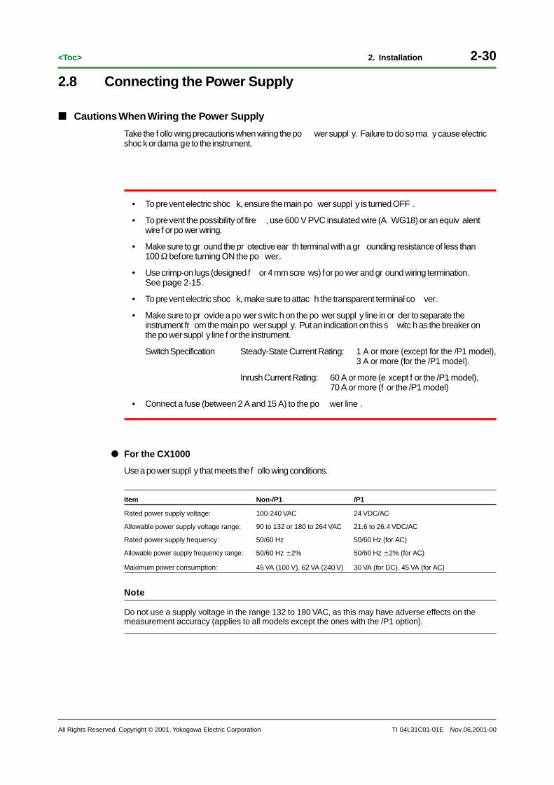
2.8 Connecting the Power Supply
Cautions When Wiring the Power Supply
Take the f ollo wing precautions when wiring the po wer suppl y. Failure to do so ma y cause electricshoc k or dama ge to the instrument.
• To prevent electric shoc k, ensure the main po wer suppl y is turned OFF .
• To prevent the possibility of fire , use 600 V PVC insulated wire (A WG18) or an equiv alentwire f or po wer wiring.
• Make sure to gr ound the pr otective ear th terminal with a gr ounding resistance of less than100 Ω before turning ON the po wer.
• Use crimp-on lugs (designed f or 4 mm scre ws) for po wer and gr ound wiring termination.See page 2-15.
• To prevent electric shoc k, make sure to attac h the transparent terminal co ver.
• Make sure to pr ovide a po wer switc h on the po wer suppl y line in or der to separate theinstrument fr om the main po wer suppl y. Put an indication on this s witc h as the breaker onthe po wer suppl y line f or the instrument.
Switch Specification Steady-State Current Rating: 1 A or more (except for the /P1 model),3 A or more (for the /P1 model).
Inrush Current Rating: 60 A or more (e xcept f or the /P1 model),70 A or more (f or the /P1 model)
• Connect a fuse (between 2 A and 15 A) to the po wer line .
For the CX1000
Use a power suppl y that meets the f ollo wing conditions.
Item Non-/P1 /P1
Rated power supply voltage: 100-240 VAC 24 VDC/AC
Allowable power supply voltage range: 90 to 132 or 180 to 264 VAC 21.6 to 26.4 VDC/AC
Rated power supply frequency: 50/60 Hz 50/60 Hz (for AC)
Allowable power supply frequency range: 50/60 Hz 2% 50/60 Hz 2% (for AC)
Maximum power consumption: 45 VA (100 V), 62 VA (240 V) 30 VA (for DC), 45 VA (for AC)
Note
Do not use a supply voltage in the range 132 to 180 VAC, as this may have adverse effects on themeasurement accuracy (applies to all models except the ones with the /P1 option).
Nov.06,2001-00

All Rights Reserved. Copyright © 2001, Yokogawa Electric Corporation TI 04L31C01-01E
2-31<Toc> 2. Installation
Wiring Procedure
1. Turn OFF the instrument and remo ve the transparent po wer terminal co ver.
2. Connect the po wer suppl y wires and the pr otective gr ound wire to the po wer terminals.
L N
Non-/P1 model
/P1(24 V DC/AC power supply)
Power Cord
Protective ground cord
3. Replace the po wer terminal co ver, and fasten it with scre ws.
For the CX2000
Use a power suppl y that meets the f ollo wing conditions.
Item Non-/P1 /P1
Rated power supply: 100-120 VAC 24 VDC/AC
Allowable power supply voltage range: 90 to 132 or 180 to 264 VAC 21.6 to 26.4 VDC/AC
Rated power supply frequency: 50/60 Hz 50/60 Hz (for AC)
Allowable power supply frequency range: 50/60 Hz 2% 50/60 Hz 2% (for AC)
Maximum power consumption: 65 VA (100 V), 105 VA (240 V) 54 VA (for DC) 76 VA (for AC)
Note
Do not use a supply voltage in the range 132 to 180 VAC, as this may have adverse effects on themeasurement accuracy (applies to all models except the ones with the /P1 option).
Wiring Procedure
1. Turn OFF the instrument and remo ve the transparent po wer terminal co ver.
2. Connect the po wer suppl y wires and the pr otective gr ound wire to the po wer terminals.
NL
AC~106VA MAX50/60Hz
100-240V 24V DC
24V AC~ 76VA MAX
L(+) N(-)
50/60Hz
54VA MAX
Non-/P1 model/P1
(24 V power supply)
Power Cord
Protective ground cord
3. Replace the po wer terminal co ver, and fasten it with scre ws.
Nov.06,2001-00

Blank Page

All Rights Reserved. Copyright © 2001, Yokogawa Electric Corporation TI 04L31C01-01E
3-1<Toc> 3. Installation Environment
Nov.06,2001-00
3. Installation EnvironmentFor extended and saf e use of this instrument, it must be installed in a suitab le environment. Thischapter gives an o verview of en vironmental specifications. For complete details, refer to theCX1000 and CX2000 g eneral specifications (GS 04L31A01-01 and GS 04L31A01-02).

3-2
All Rights Reserved. Copyright © 2001, Yokogawa Electric Corporation
<Toc>
TI 04L31C01-01E
3. Installation Environment
Nov.06,2001-00
Item
Temperature
Humidity
Effects of operating conditions
Supply current
Dielectric strength
Insulation resistance
Grounding
Noise
Dustproof and waterproof
Vibration
Safety and EMC standards
Normal operating conditio
Shipping requirements
Normal operating conditions
Frequency
Power consumption
Normal operating conditions
Transport and storage conditions
Transport and storage conditions
Normal model(50/60 Hz)
Common mode noise voltage(50/60 Hz)
Maximum noise between channels voltage (50/60 Hz)
Ambient temperature: (temperature variations of 10°C)
CX2000CX1000
–25 to 60°C20 to 80% RH
5 to 95% RH
±(0.1% of rdg +1 digits) or less (voltage/TC range)
±(0.1% of rdg +2 digits) or less (RTD range)
0 to 50°C
100 to 110 V AC ±10%200 to 220 V AC ± 10%
50/60Hz ± 2%
1000 V AC/minute C (50/60 Hz)
Not acceptable
392 m/s2 or less (while packed)
CSA22.2No.1010. 1 acquisition, EN61010-1 Installation category conformity (overvoltage category) 1 *4
pollution degree 2 *5
Conforms to EMC standard: EN61326-1
20 MΩ or more, 30 or more
D type ground
250 V ACrms or less for all ranges
250 V ACrms or lower
IEC529-IP65, NEMANo.250 Type 4 compliant (excluding ice-forming tests)
DC voltage: The peak value including the signal must be less than 1.2 times the measuring range.Thermocouple: The peak value including the signal must be less than 1.2 times the measuring range.RTD: 50 mV or less
*2 *3
1500 V AC, 1 minute/1 minute (50/60 Hz)
Other
*1
At 5 to 40°CNo condensation allowed
Excluding the reference junction compensation
Power supply to ground terminal
Contact output terminal to ground terminal
Measurement input terminal to ground terminal
Between measuring input terminals
Between each terminal and ground terminal
*1: When floppy or zip disk are in operation: 5-40°C*2: CX1000 power consumption
Power supply
100 V AC
240 V AC
Approx. 32 VA
Approx. 47 VA
With LCD saver ON Normal operation
45 VA
62 VA
Maximum
Approx. 30 VA
Approx. 42 VA
*3: CX2000 power consumption:
Power supply
100 V AC
240 V AC
Approx. 45 VA
Approx. 65 VA
With LCD saver ON Normal operation
65 VA
105 VA
Maximum
Approx. 43 VA
Approx. 62 VA
*4: nstallation Category (Overvoltage Category):Value defining an excessive voltage (including the impulse withstandvoltage rating, applies to electronic devices powered from fixedinstallations such as switchboards).
*5: Pollution Degree: Applies to the degree of adhesion of a solid, liquid, or gas which deteriorates withstand voltage orsurface resistivity (usually only applies to atmospheric conditions in the room (non-conductivepollution)).

All Rights Reserved. Copyright © 2001, Yokogawa Electric Corporation TI 04L31C01-01E
Rev-i<Toc>
Nov.06,2001-00
Technical Information Revision Information
Document name : DAQSTATION CX1000/CX2000 Control and Measurement Station Installation
Guidance
Document No. : TI 04L31C01-01E
November/2001/First EditionNew Publish

Blank Page


![User’s Manual - Yokogawa Electriccdn2.us.yokogawa.com/IM01C22T01-01EN_008.pdf · Contents of this User’s Manual for HART Protocol ... Call "Device setup" and press [→]. 3) Call](https://static.fdocuments.us/doc/165x107/5b0e2c577f8b9af65e8eb0d5/users-manual-yokogawa-of-this-users-manual-for-hart-protocol-call-device.jpg)