Technical Information Tankvision NXA820, NXA821, NXA822 · TI419F/00/en/05.08 Technical Information...
44
TI419F/00/en/05.08 Technical Information Tankvision NXA820, NXA821, NXA822 Inventory Management System with completely integrated software for operation via standard web browser Application Tankvision is a dedicated tank inventory system which is operated by a standard web browser and does not require proprietary software or licensing costs. Tankvision is based on a distributed architecture on a Local Area Network (LAN). Due to its modular structure it can be adjusted to any application. It is ideally suited for small tank farms with only a couple of tanks, but also for large refineries with hundreds of tanks. Tankvision consists of the following components: • Tankvision NXA820 (Tank Scanner) scans parameters from tank gauges and performs tank calculations • Tankvision NXA821 (Data Concentrator) summarizes data from various Tank Scanners NXA820 • Tankvision NXA822 (Host Link) provides data to host systems (such as PLC or DCS) via Modbus Your benefits • License-free • Approved for custody transfer applications according to NMI and PTB (in preparation) • Global system engineering and service support • A robust industrial operating system with embedded software ensures high stability and availability. • Modular design; easily adjustable to any application; can be upgraded as required • Configuration, commissioning and operation via web browser; no proprietary software required • Access for up to 10 users per Tankvision component from any connected PC • Common hardware platform for all components; no hard disc or fans - no wearout • Volume calculations and correction included according to international standards (API/ASTM/IP tables) in Tank Scanner NXA820 • Predefined or customized operator screens for typical operation of a tank farm
Transcript of Technical Information Tankvision NXA820, NXA821, NXA822 · TI419F/00/en/05.08 Technical Information...

TI419F/00/en/05.08
Technical Information
Tankvision NXA820, NXA821, NXA822
Inventory Management System
with completely integrated software
for operation via standard web browser
Application
Tankvision is a dedicated tank inventory system which is
operated by a standard web browser and does not require
proprietary software or licensing costs.
Tankvision is based on a distributed architecture on a
Local Area Network (LAN). Due to its modular structure
it can be adjusted to any application. It is ideally suited
for small tank farms with only a couple of tanks, but also
for large refineries with hundreds of tanks.
Tankvision consists of the following components:
• Tankvision NXA820 (Tank Scanner)
scans parameters from tank gauges and performs tank
calculations
• Tankvision NXA821 (Data Concentrator)
summarizes data from various Tank Scanners NXA820
• Tankvision NXA822 (Host Link)
provides data to host systems (such as PLC or DCS) via
Modbus
Your benefits
• License-free
• Approved for custody transfer applications according
to NMI and PTB (in preparation)
• Global system engineering and service support
• A robust industrial operating system with embedded
software ensures high stability and availability.
• Modular design; easily adjustable to any application;
can be upgraded as required
• Configuration, commissioning and operation via web
browser; no proprietary software required
• Access for up to 10 users per Tankvision component
from any connected PC
• Common hardware platform for all components; no
hard disc or fans - no wearout
• Volume calculations and correction included
according to international standards (API/ASTM/IP
tables) in Tank Scanner NXA820
• Predefined or customized operator screens for typical
operation of a tank farm

Tankvision NXA820, NXA821, NXA822
Table of Contents
Applications. . . . . . . . . . . . . . . . . . . . . . . . . . . . . . . . . 3 Examples of operating pages . . . . . . . . . . . . . . . . . . . . . . . . . . . . 38
Inventory control . . . . . . . . . . . . . . . . . . . . . . . . . . . . . . . . . . . . . 3
Inventory calculations . . . . . . . . . . . . . . . . . . . . . . . . . . . . . . . . . . 3
Remote configuration of measuring equipment . . . . . . . . . . . . . . . 3
Application areas . . . . . . . . . . . . . . . . . . . . . . . . . . . . . . . . . . . . . 3
Function and system design. . . . . . . . . . . . . . . . . . . . . 4
System design . . . . . . . . . . . . . . . . . . . . . . . . . . . . . . . . . . . . . . . 4
System configuration . . . . . . . . . . . . . . . . . . . . . . . . . . . . . . . . . . 4
Features . . . . . . . . . . . . . . . . . . . . . . . . . . . . . . . . . . . . . . . . . . . . 5
Typical system configurations . . . . . . . . . . . . . . . . . . . . . . . . . . . . 6
Tankvision NXA820 (Tank Scanner) . . . . . . . . . . . . . . 7
Function . . . . . . . . . . . . . . . . . . . . . . . . . . . . . . . . . . . . . . . . . . . 7
Number of tanks . . . . . . . . . . . . . . . . . . . . . . . . . . . . . . . . . . . . . 7
LAN connections . . . . . . . . . . . . . . . . . . . . . . . . . . . . . . . . . . . . . 7
Input NXA820 . . . . . . . . . . . . . . . . . . . . . . . . . . . . . . . . . . . . . . . 7
Output NXA820 . . . . . . . . . . . . . . . . . . . . . . . . . . . . . . . . . . . . . . 7
Power supply NXA820 . . . . . . . . . . . . . . . . . . . . . . . . . . . . . . . . . 8
Terminals NXA820 . . . . . . . . . . . . . . . . . . . . . . . . . . . . . . . . . . . . 9
Ambient conditions NXA820 . . . . . . . . . . . . . . . . . . . . . . . . . . . 15
Mechanical construction . . . . . . . . . . . . . . . . . . . . . . . . . . . . . . . 16
Human interface . . . . . . . . . . . . . . . . . . . . . . . . . . . . . . . . . . . . 17
Certificates and approvals . . . . . . . . . . . . . . . . . . . . . . . . . . . . . . 17
Ordering information NXA820 . . . . . . . . . . . . . . . . . . . . . . . . . . 18
Tankvision NXA821 (Data Concentrator) . . . . . . . . . 19
Function . . . . . . . . . . . . . . . . . . . . . . . . . . . . . . . . . . . . . . . . . . 19
Number of tanks . . . . . . . . . . . . . . . . . . . . . . . . . . . . . . . . . . . . 19
LAN connections . . . . . . . . . . . . . . . . . . . . . . . . . . . . . . . . . . . . 19
Output NXA821 . . . . . . . . . . . . . . . . . . . . . . . . . . . . . . . . . . . . . 19
Power supply . . . . . . . . . . . . . . . . . . . . . . . . . . . . . . . . . . . . . . . 20
Terminals NXA821 . . . . . . . . . . . . . . . . . . . . . . . . . . . . . . . . . . . 21
Ambient conditions . . . . . . . . . . . . . . . . . . . . . . . . . . . . . . . . . . 23
Mechanical construction . . . . . . . . . . . . . . . . . . . . . . . . . . . . . . . 23
Human interface . . . . . . . . . . . . . . . . . . . . . . . . . . . . . . . . . . . . 24
Certificates and approvals . . . . . . . . . . . . . . . . . . . . . . . . . . . . . . 24
Ordering information NXA821 . . . . . . . . . . . . . . . . . . . . . . . . . . 25
Tankvision NXA822 (Host Link) . . . . . . . . . . . . . . . . 27
Function . . . . . . . . . . . . . . . . . . . . . . . . . . . . . . . . . . . . . . . . . . 27
Number of tanks . . . . . . . . . . . . . . . . . . . . . . . . . . . . . . . . . . . . 27
LAN connections . . . . . . . . . . . . . . . . . . . . . . . . . . . . . . . . . . . . 27
Output NXA822 . . . . . . . . . . . . . . . . . . . . . . . . . . . . . . . . . . . . . 27
Power supply . . . . . . . . . . . . . . . . . . . . . . . . . . . . . . . . . . . . . . . 28
Terminals NXA822 . . . . . . . . . . . . . . . . . . . . . . . . . . . . . . . . . . . 28
Ambient conditions . . . . . . . . . . . . . . . . . . . . . . . . . . . . . . . . . . 34
Mechanical construction . . . . . . . . . . . . . . . . . . . . . . . . . . . . . . . 34
Human interface . . . . . . . . . . . . . . . . . . . . . . . . . . . . . . . . . . . . 35
Certificates and approvals . . . . . . . . . . . . . . . . . . . . . . . . . . . . . . 35
Ordering information NXA822 . . . . . . . . . . . . . . . . . . . . . . . . . . 36
Human interface . . . . . . . . . . . . . . . . . . . . . . . . . . . . 37
Operating concept . . . . . . . . . . . . . . . . . . . . . . . . . . . . . . . . . . . 37
Languages . . . . . . . . . . . . . . . . . . . . . . . . . . . . . . . . . . . . . . . . . 37
System requirements
of user PC . . . . . . . . . . . . . . . . . . . . . . . . . . . . . . . . . . . . . . . . . 37
2
Supplementary documentation . . . . . . . . . . . . . . . . . 40
Operating Instructions . . . . . . . . . . . . . . . . . . . . . . . . . . . . . . . . 40
Description of Instrument Functions . . . . . . . . . . . . . . . . . . . . . . 40
Trademarks . . . . . . . . . . . . . . . . . . . . . . . . . . . . . . . . 40
MODBUS . . . . . . . . . . . . . . . . . . . . . . . . . . . . . . . . . . . . . . . . . 40
Windows . . . . . . . . . . . . . . . . . . . . . . . . . . . . . . . . . . . . . . . . . . 40
Java . . . . . . . . . . . . . . . . . . . . . . . . . . . . . . . . . . . . . . . . . . . . . . 40
. . . . . . . . . . . . . . . . . . . . . . . . . . . . . . . . . . . . . . . . . . . . . . . . . 41
. . . . . . . . . . . . . . . . . . . . . . . . . . . . . . . . . . . . . . . . . . . . . . . . . 42
Endress+Hauser
Tankvision NXA820, NXA821, NXA822
Applications
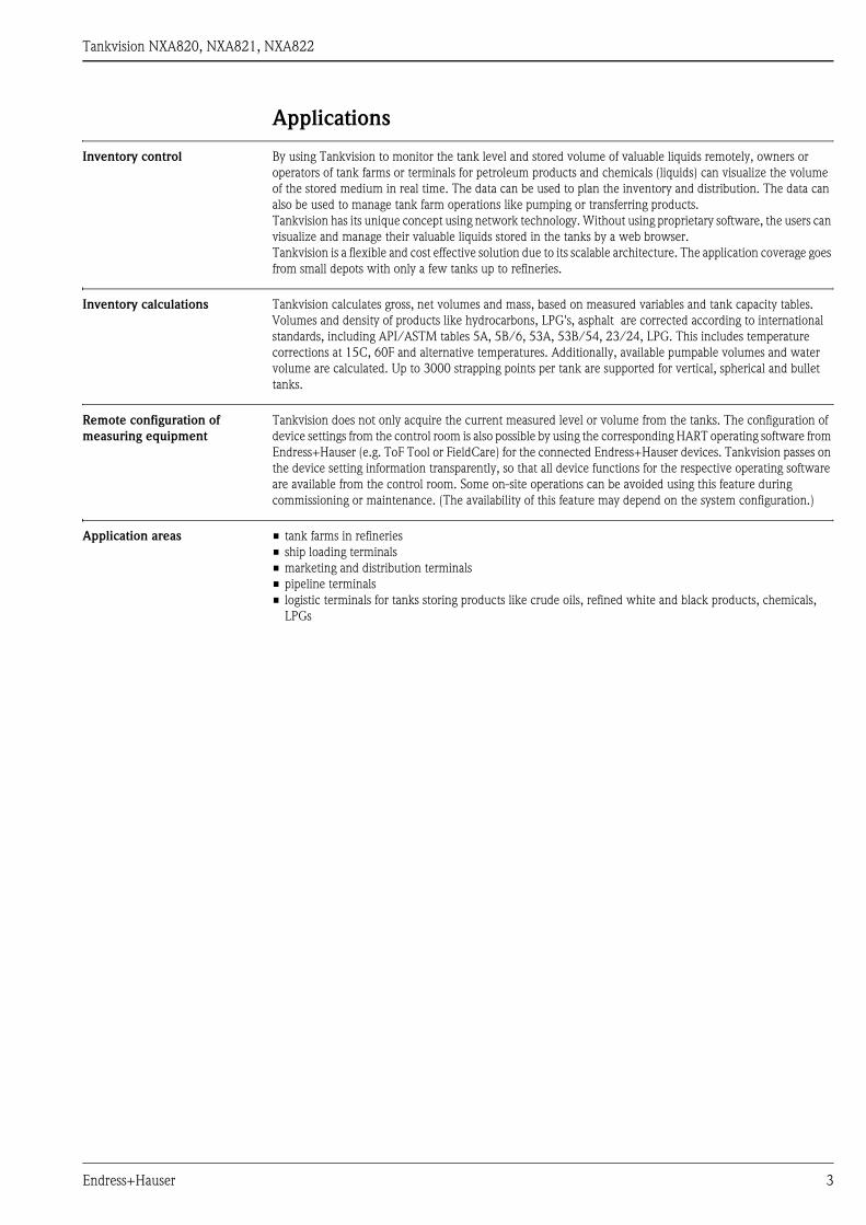
Inventory control By using Tankvision to monitor the tank level and stored volume of valuable liquids remotely, owners or
operators of tank farms or terminals for petroleum products and chemicals (liquids) can visualize the volume
of the stored medium in real time. The data can be used to plan the inventory and distribution. The data can
also be used to manage tank farm operations like pumping or transferring products.
Tankvision has its unique concept using network technology. Without using proprietary software, the users can
visualize and manage their valuable liquids stored in the tanks by a web browser.
Tankvision is a flexible and cost effective solution due to its scalable architecture. The application coverage goes
from small depots with only a few tanks up to refineries.
Inventory calculations Tankvision calculates gross, net volumes and mass, based on measured variables and tank capacity tables.
Volumes and density of products like hydrocarbons, LPG's, asphalt are corrected according to international
standards, including API/ASTM tables 5A, 5B/6, 53A, 53B/54, 23/24, LPG. This includes temperature
corrections at 15C, 60F and alternative temperatures. Additionally, available pumpable volumes and water
volume are calculated. Up to 3000 strapping points per tank are supported for vertical, spherical and bullet
tanks.
Remote configuration of
measuring equipment
Tankvision does not only acquire the current measured level or volume from the tanks. The configuration of
device settings from the control room is also possible by using the corresponding HART operating software from
Endress+Hauser (e.g. ToF Tool or FieldCare) for the connected Endress+Hauser devices. Tankvision passes on
the device setting information transparently, so that all device functions for the respective operating software
are available from the control room. Some on-site operations can be avoided using this feature during
commissioning or maintenance. (The availability of this feature may depend on the system configuration.)
Application areas • tank farms in refineries
• ship loading terminals
• marketing and distribution terminals
• pipeline terminals
• logistic terminals for tanks storing products like crude oils, refined white and black products, chemicals,
LPGs
Endress+Hauser 3

Tankvision NXA820, NXA821, NXA822
Function and system design
System design Tank management visualization without proprietary software
Tankvision is the first tank management visualization system providing its functionality without the need to
have proprietary software installed and maintained on a PC. The main functionality is realized by embedded
web pages in the Tankvision components. Tankvision uses an industrial proven operating system and provides
high availability. Tankvision is not based on a PC platform and runs independent of connected PCs. This
eliminates the need to maintain a specialized PC with a Windows operating system and necessary updates and
hot fixes. Tankvision web pages can be accessed from a standard PC with a web browser and the Java Runtime
Environment only. Multiple users with different roles can simultaneously log in to each Tankvision component.
Additional users can be added as required. There are no multi-user licence fees.
Distributed architecture and scalability
Tankvision is based on a distributed architecture on a Local Area Network (LAN). Coordinated components
perform all inventory management tasks. The modular design makes it easy to enlarge the system whenever
required and to add further tank areas.
Thus, Tankvision is fully scalable and is ideally suited for applications of any size - from small tank farms to
large refineries.
Common hardware platform
The Tankvision components have dedicated tasks in a system, but have a common architecture, based on a 32
Bit processor. The embedded tank management software uses a multi-threaded real time operating system
(RTOS), specifically designed for industrial applications. The hardware is designed without wear-out
components like hard discs or fans. This guarantees high reliability.
System configuration Configuration of the components
Each Tankvision component has its own data base and a web server. The components are connected and
exchange data with time stamp and status information. Data is optionally encrypted and secured by a CRC
checksum.
The Tankvision components are configured with static IP addresses, which are reserved on a DHCP network.
The configuration pages are embedded in the Tankvision components and allow configuration of Tankvision
via a connected web browser without configuration software. No Internet access is necessary, as all pages are
loaded from the Tankvision system itself.
Configuration of the connected tank gauges/sensors
(available for Windows XP SP1; in preparation for Windows XP SP2)
Tankvision supports connection of Endress+Hauser configuration tools (e.g. ToF Tool or FieldCare) via LAN.
This enables configuration of the tank gauges if they support remote configuration (e.g. Tank Side Monitor
NRF590 and the level radars Micropilot S FMR53x/FMR54x).
The tank gauges must be connected to the Tank Scanner NXA820 in one of the following ways:
• via a field protocol
• via HART to the Tank Side Monitor NRF590 (version 02.04) which in turn is connected via one of the
following protocols to the Tank Scanner NXA820:
– MODBUS
– Sakura V1
– Whessoematic WM550 (in preparation)
4 Endress+Hauser
Tankvision NXA820, NXA821, NXA822
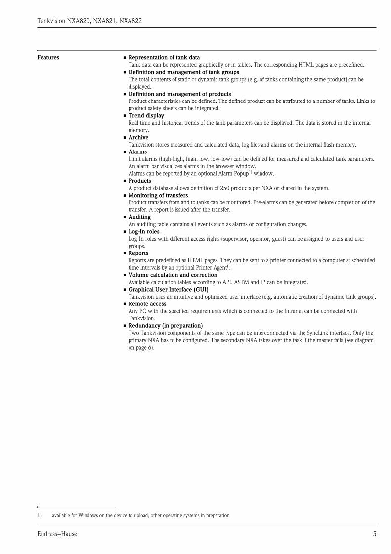
Features • Representation of tank data
Tank data can be represented graphically or in tables. The corresponding HTML pages are predefined.
• Definition and management of tank groups
The total contents of static or dynamic tank groups (e.g. of tanks containing the same product) can be
displayed.
• Definition and management of products
Product characteristics can be defined. The defined product can be attributed to a number of tanks. Links to
product safety sheets can be integrated.
• Trend display
Real time and historical trends of the tank parameters can be displayed. The data is stored in the internal
memory.
• Archive
Tankvision stores measured and calculated data, log files and alarms on the internal flash memory.
• Alarms
Limit alarms (high-high, high, low, low-low) can be defined for measured and calculated tank parameters.
An alarm bar visualizes alarms in the browser window.
Alarms can be reported by an optional Alarm Popup1) window.
• Products
A product database allows definition of 250 products per NXA or shared in the system.
• Monitoring of transfers
Product transfers from and to tanks can be monitored. Pre-alarms can be generated before completion of the
transfer. A report is issued after the transfer.
• Auditing
An auditing table contains all events such as alarms or configuration changes.
• Log-In roles
Log-In roles with different access rights (supervisor, operator, guest) can be assigned to users and user
groups.
• Reports
Reports are predefined as HTML pages. They can be sent to a printer connected to a computer at scheduled
time intervals by an optional Printer Agent1.
• Volume calculation and correction
Available calculation tables according to API, ASTM and IP can be integrated.
• Graphical User Interface (GUI)
Tankvision uses an intuitive and optimized user interface (e.g. automatic creation of dynamic tank groups).
• Remote access
Any PC with the specified requirements which is connected to the Intranet can be connected with
Tankvision.
• Redundancy (in preparation)
Two Tankvision components of the same type can be interconnected via the SyncLink interface. Only the
primary NXA has to be configured. The secondary NXA takes over the task if the master fails (see diagram
on page 6).
1) available for Windows on the device to upload; other operating systems in preparation
Endress+Hauser 5
Tankvision NXA820, NXA821, NXA822
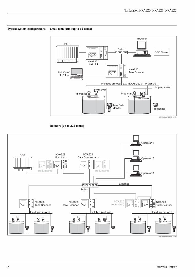
Typical system configurations Small tank farm (up to 15 tanks)
L00-NXA82xxx-02-00-00-en-001
Refinery (up to 225 tanks)
L00-NXA82xxx-02-00-00-en-002
NXA820
NXA822
NXA820Tank Scanner
NXA822Host Link
Switch
FieldCare/ToF Tool
Tank SideMonitor Promonitor
Browser
OPC Server
Proservo
ProthermoMicropilot
Prothermo
PLC
Fieldbus protocol (e.g. MODBUS, V1, WM550*)
*in preparation
NXA820Tank Scanner
NXA820Tank Scanner
Switch
NXA820Tank Scanner
NXA820
NXA821Data Concentrator
NXA820
NXA822Host Link
NXA820 NXA820 NXA820 NXA820
Ethernet
NXA820 NXA820
DCS
Operator 1
Operator 2
Operator 3
NXA820(redundant)
Fieldbus protocol Fieldbus protocol Fieldbus protocol
(redundant) (redundant)
6 Endress+Hauser

Tankvision NXA820, NXA821, NXA822
Tankvision NXA820 (Tank Scanner)
Function • The Tank Scanner NXA820 connects multiple tank gauges from up to 15 tanks via one field-loop. The Tank
Scanner NXA820 supports different field protocols (Modbus EIA485, Sakura V1, Whessoematic WM550).
• The measured values are transmitted by the network and visualized on HTML pages.
• The Tank Scanner NXA820 can be used stand-alone for small tank farms, but also be integrated into a large
system for use in refineries.
• The Tank Scanner NXA820 is equipped with a full set of tank inventory calculations. The calculations are
based on various international standards such as API, ASTM, IP and many others. Measured values are used
to calculate volume and mass.
Number of tanks
LAN connections System LAN port
100 BASE-TX, Full/Half Duplex, 100 Mbit, Shielded RJ45 connector
Connects the NXA820 Tank Scanner to the Local Area Network (LAN)
Sync-Link LAN port (in preparation)
100 BASE-TX, Full/Half Duplex, 100 Mbit, Shielded RJ45 connector
Connects the NXA820 Tank Scanner (e.g. primary) to an optional redundant unit (e.g secondary), to make sure
the two devices remain synchronized with each other. If the primary unit fails, the secondary NXA820 Tank
Scanner takes over operation without system interruption (see diagram on page 6).
Service LAN port
100 BASE-TX, Full/Half Duplex, 100 Mbit, Shielded RJ45 connector
Connects the NXA820 Tank Scanner to a local computer only for local commissioning and service operations.
The computer does not become part of the local area network the NXA820 Tank Scanner is connected to
through the System LAN port.
This port has a fixed IP address and can also provide the connected computer automatically with a compatible
IP address using a DHCP server built into the NXA820 Tank Scanner. For this automatic IP function to work
the computer must be set to obtain its IP address using a DHCP server
! Note!
All LAN ports support Auto-MDIX. This system automatically detects the type of cable connected (either
straight or crossed) and adjusts itself to match. With this feature you do not need to obtain special crossed cables
to interconnect Tankvision components.
Input NXA820 Fieldbus protocols
The Tank Scanner NXA820 is available with the following field protocols:
• MODBUS EIA485 master, max. 15 gauges
• Sakura V1, max. 10 gauges
• Whessoematic 550, max. 15 gauges (in preparation)
Output NXA820 NXA Status Relay
• potential free relay, SPDT
• normally-closed when NXA is operating normally, open when NXA is powered off or in fault status
• switching power:
– 25 VDC, 100 W
– 250 VAC, 4 A, 1000VA
Protocol max. number of tanks per NXA820
MODBUS EIA485 15
Sakura V1 10
Whessoematic WM550
(in preparation)
15
Endress+Hauser 7
Tankvision NXA820, NXA821, NXA822
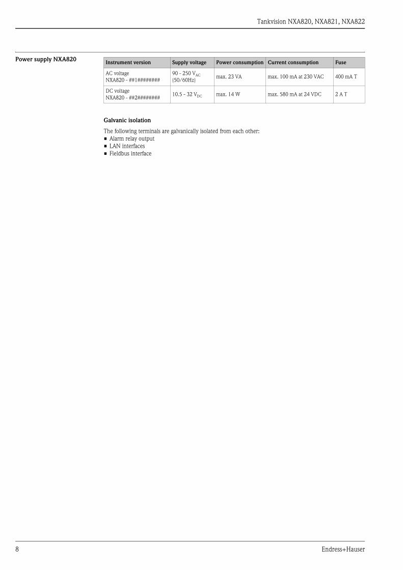
Power supply NXA820
Galvanic isolation
The following terminals are galvanically isolated from each other:
• Alarm relay output
• LAN interfaces
• Fieldbus interface
Instrument version Supply voltage Power consumption Current consumption Fuse
AC voltage
NXA820 - ##1########
90 - 250 VAC
(50/60Hz)max. 23 VA max. 100 mA at 230 VAC 400 mA T
DC voltage
NXA820 - ##2########10.5 - 32 VDC max. 14 W max. 580 mA at 24 VDC 2 A T
8 Endress+Hauser
Tankvision NXA820, NXA821, NXA822
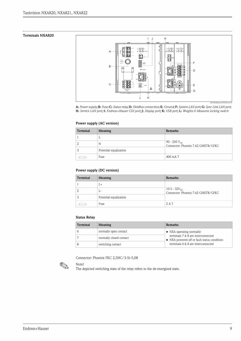
Terminals NXA820
L00-NXA82xxx-04-00-00-yy-019
A: Power supply; B: Fuse; C: Status relay; D: Fieldbus connection; E: Ground; F: System LAN port; G: Sync Link LAN port;
H: Service LAN port; I: Endress+Hauser CDI port; J: Display port; K: USB port; L: Weights & Measures locking switch
Power supply (AC version)
Power supply (DC version)
Status Relay
Connector: Phoenix FKC 2,5HC/3-St-5,08
! Note!
The depicted switching state of the relay refers to the de-energized state.
23
16
78
W &M
RESET
RESET
NXA StatusRelay
E
L+
L-
67
83
21
Fuse
PO
WE
R
10
,5..
.3
2V
DC
2 A T
10
1112
13
10
111
21
3
MODBUS
A
B
C
D
F
G
E
H
I J K
L
Terminal Meaning Remarks
1 L
90 - 250 VAC
Connector: Phoenix 7.62 GMSTB/GFKC2 N
3 Potential equalization
Fuse 400 mA T
Terminal Meaning Remarks
1 L+
10.5 - 32VDC
Connector: Phoenix 7.62 GMSTB/GFKC2 L-
3 Potential equalization
Fuse 2 A T
Terminal Meaning Remarks
6 normally open contact • NXA operating normally:
terminals 7 & 8 are interconnected
• NXA powered off or fault status condition:
terminals 6 & 8 are interconnected
7 normally closed contact
8 switching contact
Endress+Hauser 9
Tankvision NXA820, NXA821, NXA822
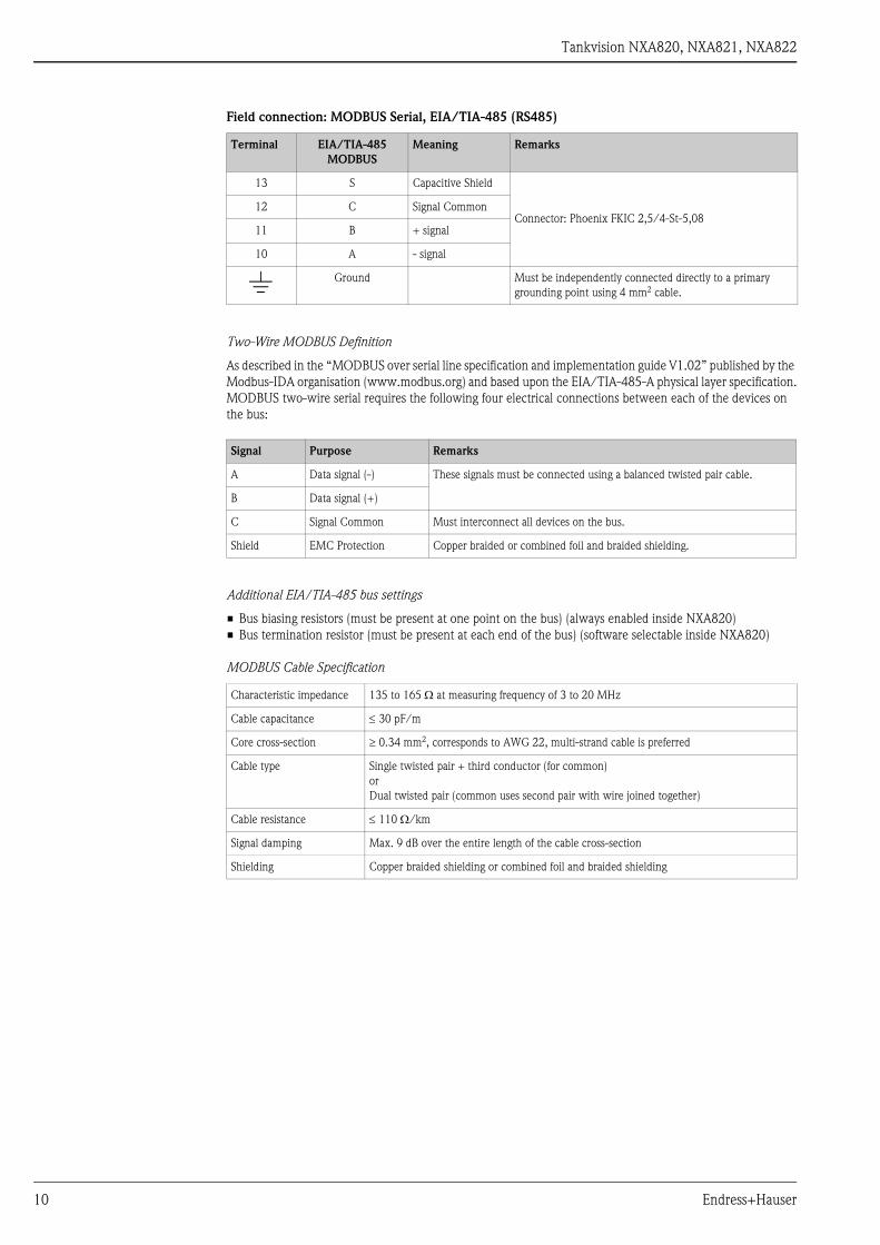
Field connection: MODBUS Serial, EIA/TIA-485 (RS485)
Two-Wire MODBUS Definition
As described in the “MODBUS over serial line specification and implementation guide V1.02” published by the
Modbus-IDA organisation (www.modbus.org) and based upon the EIA/TIA-485-A physical layer specification.
MODBUS two-wire serial requires the following four electrical connections between each of the devices on
the bus:
Additional EIA/TIA-485 bus settings
• Bus biasing resistors (must be present at one point on the bus) (always enabled inside NXA820)
• Bus termination resistor (must be present at each end of the bus) (software selectable inside NXA820)
MODBUS Cable Specification
Terminal EIA/TIA-485
MODBUS
Meaning Remarks
13 S Capacitive Shield
Connector: Phoenix FKIC 2,5/4-St-5,0812 C Signal Common
11 B + signal
10 A - signal
) Ground Must be independently connected directly to a primary
grounding point using 4 mm2 cable.
Signal Purpose Remarks
A Data signal (-) These signals must be connected using a balanced twisted pair cable.
B Data signal (+)
C Signal Common Must interconnect all devices on the bus.
Shield EMC Protection Copper braided or combined foil and braided shielding.
Characteristic impedance 135 to 165 Ω at measuring frequency of 3 to 20 MHz
Cable capacitance ≤ 30 pF/m
Core cross-section ≥ 0.34 mm2, corresponds to AWG 22, multi-strand cable is preferred
Cable type Single twisted pair + third conductor (for common)
or
Dual twisted pair (common uses second pair with wire joined together)
Cable resistance ≤ 110 Ω/km
Signal damping Max. 9 dB over the entire length of the cable cross-section
Shielding Copper braided shielding or combined foil and braided shielding
10 Endress+Hauser
Tankvision NXA820, NXA821, NXA822
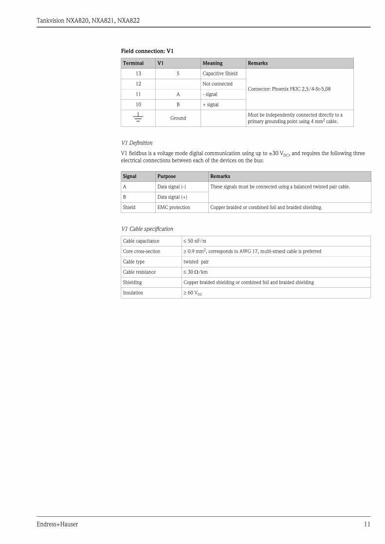
Field connection: V1
V1 Definition
V1 fieldbus is a voltage mode digital communication using up to ±30 VDC, and requires the following three
electrical connections between each of the devices on the bus:
V1 Cable specification
Terminal V1 Meaning Remarks
13 S Capacitive Shield
Connector: Phoenix FKIC 2,5/4-St-5,0812 Not connected
11 A - signal
10 B + signal
) GroundMust be independently connected directly to a
primary grounding point using 4 mm2 cable.
Signal Purpose Remarks
A Data signal (-) These signals must be connected using a balanced twisted pair cable.
B Data signal (+)
Shield EMC protection Copper braided or combined foil and braided shielding
Cable capacitance ≤ 50 nF/m
Core cross-section ≥ 0.9 mm2, corresponds to AWG 17, multi-strand cable is preferred
Cable type twisted pair
Cable resistance ≤ 30 Ω/km
Shielding Copper braided shielding or combined foil and braided shielding
Insulation ≥ 60 VDC
Endress+Hauser 11
Tankvision NXA820, NXA821, NXA822
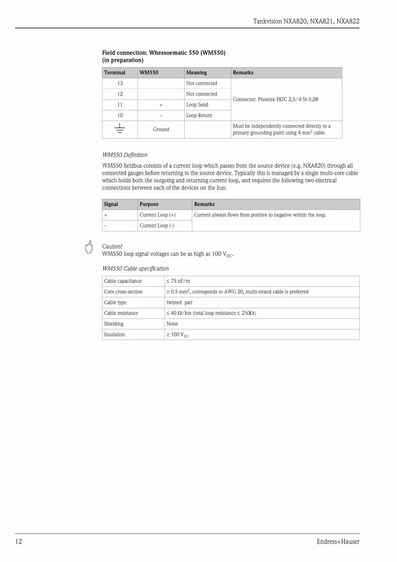
Field connection: Whessoematic 550 (WM550)
(in preparation)
WM550 Definition
WM550 fieldbus consists of a current loop which passes from the source device (e.g. NXA820) through all
connected gauges before returning to the source device. Typically this is managed by a single multi-core cable
which holds both the outgoing and returning current loop, and requires the following two electrical
connections between each of the devices on the bus:
" Caution!
WM550 loop signal voltages can be as high as 100 VDC.
WM550 Cable specification
Terminal WM550 Meaning Remarks
13 Not connected
Connector: Phoenix FKIC 2,5/4-St-5,0812 Not connected
11 + Loop Send
10 - Loop Return
) GroundMust be independently connected directly to a
primary grounding point using 4 mm2 cable.
Signal Purpose Remarks
+ Current Loop (+) Current always flows from positive to negative within the loop.
- Current Loop (-)
Cable capacitance ≤ 75 nF/m
Core cross-section ≥ 0.5 mm2, corresponds to AWG 20, multi-strand cable is preferred
Cable type twisted pair
Cable resistance ≤ 40 Ω/km (total loop resistance ≤ 250Ω)
Shielding None
Insulation ≥ 100 VDC
12 Endress+Hauser
Tankvision NXA820, NXA821, NXA822
Shielding and Grounding
When planning the shielding and grounding for a fieldbus system, there are three important points to consider:
• Electromagnetic compatibility (EMC)
• Explosion protection
• Safety of the personnel
To ensure the optimum electromagnetic compatibility of systems, it is important that the system components
and above all cables, which connect the components, are shielded and that no portion of the system is
unshielded. Ideally, the cable shields are connected to the normally metal housings of the connected field
devices. Since these are generally connected to the protective earth, the shield of the bus cable is grounded
many times. Keep the stripped and twisted lengths of cable shield to the terminals as short as possible.
This approach, which provides the best electromagnetic compatibility and personnel safety, can be used
without restriction in systems with good potential equalization.
In the case of systems without potential equalization, a power supply frequency (50/60 Hz) equalizing current
can flow between two grounding points which, in unfavourable cases, e.g. when it exceeds the permissible
shield current, may destroy the cable.
To suppress the low frequency equalizing currents on systems without potential equalization, it is therefore
recommended to connect the cable shield directly to the building ground (or protective earth) at one end only
and to use capacitive coupling to connect all other grounding points.
The NXA820 provides two grounding points for the shield, close to the fieldbus interface connector:
• The “)” terminal, which should already be connected directly to ground
• The “S” terminal (13), which provides capacitive connection to the “)” terminal
" Caution!
The legal EMC requirements are fulfilled only when the cable shield is grounded on both sides!
Endress+Hauser 13
Tankvision NXA820, NXA821, NXA822
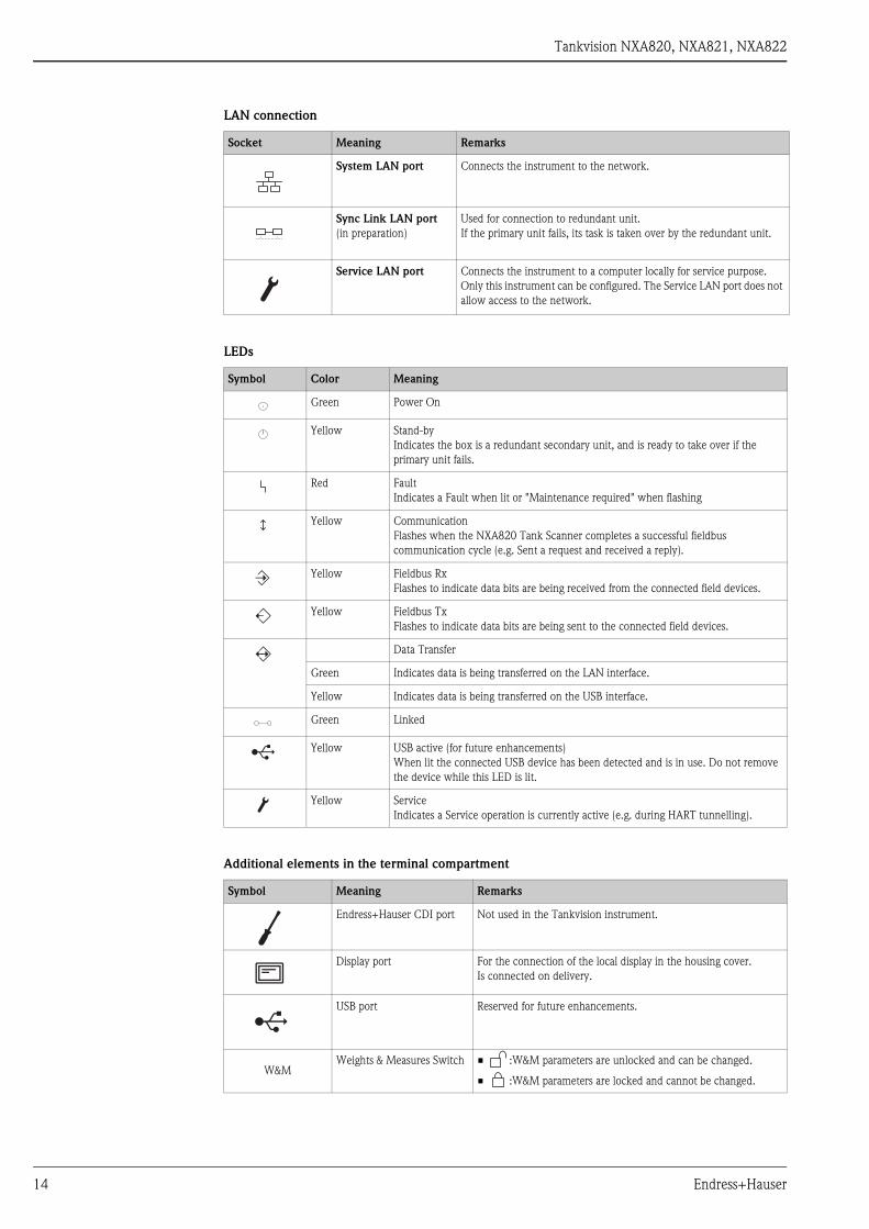
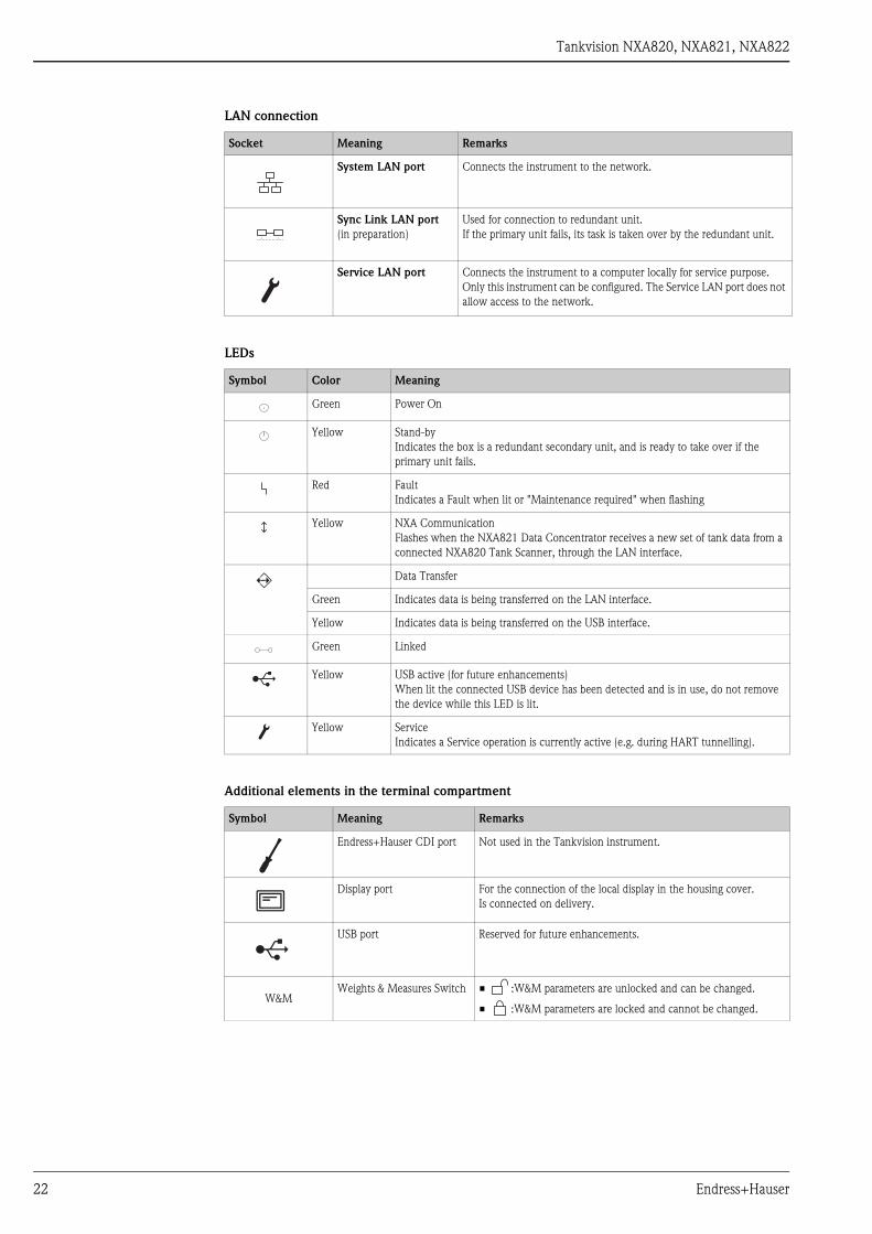
LAN connection
LEDs
Additional elements in the terminal compartment
Socket Meaning Remarks
System LAN port Connects the instrument to the network.
Sync Link LAN port
(in preparation)
Used for connection to redundant unit.
If the primary unit fails, its task is taken over by the redundant unit.
Service LAN port Connects the instrument to a computer locally for service purpose.
Only this instrument can be configured. The Service LAN port does not
allow access to the network.
Symbol Color Meaning
Green Power On
Yellow Stand-by
Indicates the box is a redundant secondary unit, and is ready to take over if the
primary unit fails.
Red Fault
Indicates a Fault when lit or "Maintenance required" when flashing
Yellow Communication
Flashes when the NXA820 Tank Scanner completes a successful fieldbus
communication cycle (e.g. Sent a request and received a reply).
Yellow Fieldbus Rx
Flashes to indicate data bits are being received from the connected field devices.
Yellow Fieldbus Tx
Flashes to indicate data bits are being sent to the connected field devices.
Data Transfer
Green Indicates data is being transferred on the LAN interface.
Yellow Indicates data is being transferred on the USB interface.
Green Linked
Yellow USB active (for future enhancements)
When lit the connected USB device has been detected and is in use. Do not remove
the device while this LED is lit.
Yellow Service
Indicates a Service operation is currently active (e.g. during HART tunnelling).
Symbol Meaning Remarks
Endress+Hauser CDI port Not used in the Tankvision instrument.
Display port For the connection of the local display in the housing cover.
Is connected on delivery.
USB port Reserved for future enhancements.
W&MWeights & Measures Switch • :W&M parameters are unlocked and can be changed.
• :W&M parameters are locked and cannot be changed.
14 Endress+Hauser
Tankvision NXA820, NXA821, NXA822
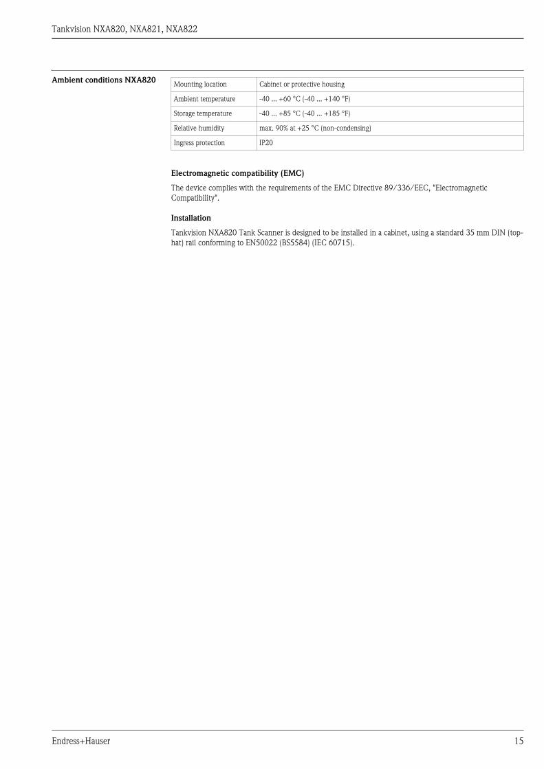
Ambient conditions NXA820
Electromagnetic compatibility (EMC)
The device complies with the requirements of the EMC Directive 89/336/EEC, "Electromagnetic
Compatibility".
Installation
Tankvision NXA820 Tank Scanner is designed to be installed in a cabinet, using a standard 35 mm DIN (top-
hat) rail conforming to EN50022 (BS5584) (IEC 60715).
Mounting location Cabinet or protective housing
Ambient temperature -40 ... +60 °C (-40 ... +140 °F)
Storage temperature -40 ... +85 °C (-40 ... +185 °F)
Relative humidity max. 90% at +25 °C (non-condensing)
Ingress protection IP20
Endress+Hauser 15

Tankvision NXA820, NXA821, NXA822
Mechanical construction Dimensions
NXA82xxx-06-00-00-yy-003
Dimensions in mm (inch)
Materials
Housing
Polycarbonate
Colour: light grey
Front cover
Polyamide PA6
Colour: grey
Fixing slide (for fastening on the top-hat rail)
Polyamide PA6
Colour: black
43 (1.7”)
35 (1.4”)
104 (4.1”)
150 (5.9”)140 (5.5”)
100 (3.9)
Gap ≥ 50 (2”)
Gap ≥ 50 (2”)
16 Endress+Hauser

Tankvision NXA820, NXA821, NXA822
Human interface Display module
L00-NXA820xx-07-00-00-yy-001
(a): IP address; (b): date and time; (c): instrument tag; (d): W&M switch status
LEDs
Certificates and approvals NMi
W&M approval according to OIML R 85 (in preparation)
PTB
Innerstaatliche Bauartzulassung (in preparation)
NXA
(a)
(c)
(b)
(d)
Symbol Color Meaning
Green/Red Green = Power On
Red = Indicates a Fault when lit or "Maintenance required" when flashing.
Yellow Communication
Flashes when the NXA820 Tank Scanner completes a successful fieldbus
communication cycle (e.g. Sent a request and received a reply).
Yellow Service
Indicates a Service operation is currently active (e.g. during HART tunnelling).
Yellow Stand-by
Indicates the box is a redundant secondary unit, and is ready to take over if the
primary unit fails.
Endress+Hauser 17

Tankvision NXA820, NXA821, NXA822
Ordering information
NXA820010 Approval
A Non-hazardous area
020 Field Communication; Input
8 Sakura V1 protocol, max. 10 instruments
1 Whessoematic 550, max. 15 instruments (in preparation)
4 MODBUS EIA485 master, max. 15 instruments
Y Special version, to be specified
030 Power supply
1 90-250 VAC 50/60Hz
2 10.5-32 VDC
9 Special version, to be specified
040 Inventory calculations
1 Oil+gas
9 Special version, to be specified
050 Data Archive Memory Size
D 1GB; 15 parameters/min; 90 days
Y Special version, to be specified
060 Local Operation
1 status display
9 Special version, to be specified
070 Operation language
A English
Y Special version, to be specified
080 Housing
1 DIN rail mounting PBT, IP20
9 Special version, to be specified
090 Redundancy
1 w/o
2 activated (in preparation)
9 Special version, to be specified
100 Custody Transfer Approval
0 not selected
1 NMI + PTB type (in preparation)
9 Special version, to be specified
110 Additional Option
A Basic version
Y Special version, to be specified
NXA820 - complete product designation
18 Endress+Hauser

Tankvision NXA820, NXA821, NXA822
Tankvision NXA821 (Data Concentrator)
Function • The NXA821 Tankvision Data Concentrator is the enhanced solution for large tank farms and refineries. The
Data Concentrator is required if:
– the plant contains more than one field loop (each of which has its own Tank Scanner NXA820)
– tanks of more than one Tank Scanner NXA820 are to be grouped
• The Data Concentrator collects the data of several Tank Scanner units and enables reconciliation and
totalization of the tank data of many or all tanks in structured groups.
• Alarms and events from all connected Tank Scanners NXA820 can be shown in a common screen. Any tank
of the system can be assigned to any tank group, regardless of the Tank Scanner it is linked to. This ensures
the highest possible flexibility for the plant or tank farm.
• An alarm pop-up shows alarms of all connected Tank Scanners NXA820 even if the web browser is closed.
• A central log-in allows access to all Tank Scanners NXA820 in the network without having to access each
unit via its IP address. Tank details of all units can be viewed from a central location.
Number of tanks • 225 tanks2) can be allocated to each Data Concentrator NXA821. Each of these tanks must have been
allocated to a Tank Scanner NXA820 beforehand.
If more than 225 tanks are to be integrated in the system, multiple Data Concentrators NXA821 have to be
used.
• Tanks from up to 15 different Tank Scanners NXA820 can be integrated in this way3).
If more than 15 Tank Scanners NXA820 are involved , multiple Data Concentrators NXA821 have to be
used.
LAN connections System LAN port
100 BASE-TX, Full/Half Duplex, 100 Mbit, Shielded RJ45 connector
Connects the NXA821 Data Concentrator to the Local Area Network (LAN)
Sync-Link LAN port (in preparation)
100 BASE-TX, Full/Half Duplex, 100 Mbit, Shielded RJ45 connector
Connects the NXA821 Data Concentrator (e.g. primary) to an optional redundant unit (e.g secondary), to make
sure the two devices remain synchronized with each other. If the primary unit fails, the secondary NXA821
Data Concentrator takes over operation without system interruption (see diagram on page 6).
Service LAN port
100 BASE-TX, Full/Half Duplex, 100 Mbit, Shielded RJ45 connector
Connects the NXA821 Data Concentrator to a local computer only for local commissioning and service
operations. The computer does not become part of the local area network the NXA821 Data Concentrator is
connected to through the System LAN port.
This port has a fixed IP address and can also provide the connected computer automatically with a compatible
IP address using a DHCP server built into the NXA821 Data Concentrator. For this automatic IP function to
work the computer must be set to obtain its IP address using a DHCP server
! Note!
All LAN ports support Auto-MDIX, this system automatically detects the type of cable connected (either
straight or crossed) and adjusts itself to match. With this feature you do not need to obtain special crossed cables
to interconnect Tankvision components.
Output NXA821 NXA Status relay
• potential free relay, SPDT
• normally-closed when NXA is operating normally, open when NXA is powered off or in fault status
• switching power:
– 25 VDC, 100 W
– 250 VAC, 4 A, 1000VA
2) standard: 45 tanks;
on request: more than 45 tanks, up to 225 tanks
3) standard: 4 Tank Scanners;
on request: more than 4 Tank Scanners, up to 15 Tank Scanners
Endress+Hauser 19

Tankvision NXA820, NXA821, NXA822
Power supply
Galvanic isolation
The following terminals are galvanically isolated from each other:
• Alarm relay output
• LAN interfaces
Instrument version Supply voltage Power consumption Current consumption Fuse
AC voltage
NXA821 - #1#######
90 - 250 VAC
(50/60Hz)max. 23 VA max. 100 mA at 230 VAC 400 mA T
DC voltage
NXA821 - #2#######10.5 - 32 VDC max. 14 W max. 580 mA at 24 VDC 2 A T
20 Endress+Hauser
Tankvision NXA820, NXA821, NXA822
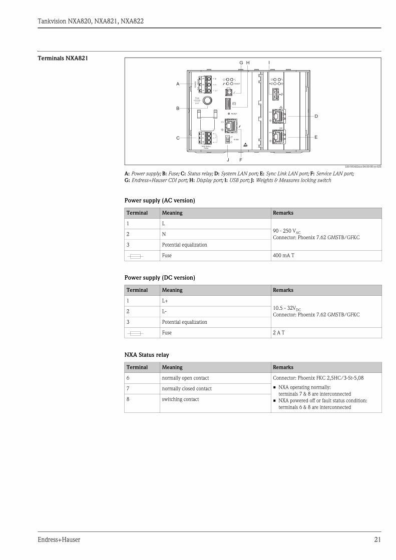
Terminals NXA821
L00-NXA82xxx-04-00-00-yy-020
A: Power supply; B: Fuse; C: Status relay; D: System LAN port; E: Sync Link LAN port; F: Service LAN port;
G: Endress+Hauser CDI port; H: Display port; I: USB port; J: Weights & Measures locking switch
Power supply (AC version)
Power supply (DC version)
NXA Status relay
23
16
78
W &M
RESET
RESET
NXA StatusRelay
E
L+
L-
67
83
21
Fuse
PO
WE
R
10
,5..
.3
2V
DC
2 A T
A
B
C
D
E
F
G H I
J
Terminal Meaning Remarks
1 L
90 - 250 VAC
Connector: Phoenix 7.62 GMSTB/GFKC2 N
3 Potential equalization
Fuse 400 mA T
Terminal Meaning Remarks
1 L+
10.5 - 32VDC
Connector: Phoenix 7.62 GMSTB/GFKC2 L-
3 Potential equalization
Fuse 2 A T
Terminal Meaning Remarks
6 normally open contact Connector: Phoenix FKC 2,5HC/3-St-5,08
• NXA operating normally:
terminals 7 & 8 are interconnected
• NXA powered off or fault status condition:
terminals 6 & 8 are interconnected
7 normally closed contact
8 switching contact
Endress+Hauser 21
Tankvision NXA820, NXA821, NXA822
LAN connection
LEDs
Additional elements in the terminal compartment
Socket Meaning Remarks
System LAN port Connects the instrument to the network.
Sync Link LAN port
(in preparation)
Used for connection to redundant unit.
If the primary unit fails, its task is taken over by the redundant unit.
Service LAN port Connects the instrument to a computer locally for service purpose.
Only this instrument can be configured. The Service LAN port does not
allow access to the network.
Symbol Color Meaning
Green Power On
Yellow Stand-by
Indicates the box is a redundant secondary unit, and is ready to take over if the
primary unit fails.
Red Fault
Indicates a Fault when lit or "Maintenance required" when flashing
Yellow NXA Communication
Flashes when the NXA821 Data Concentrator receives a new set of tank data from a
connected NXA820 Tank Scanner, through the LAN interface.
Data Transfer
Green Indicates data is being transferred on the LAN interface.
Yellow Indicates data is being transferred on the USB interface.
Green Linked
Yellow USB active (for future enhancements)
When lit the connected USB device has been detected and is in use, do not remove
the device while this LED is lit.
Yellow Service
Indicates a Service operation is currently active (e.g. during HART tunnelling).
Symbol Meaning Remarks
Endress+Hauser CDI port Not used in the Tankvision instrument.
Display port For the connection of the local display in the housing cover.
Is connected on delivery.
USB port Reserved for future enhancements.
W&MWeights & Measures Switch • :W&M parameters are unlocked and can be changed.
• :W&M parameters are locked and cannot be changed.
22 Endress+Hauser
Tankvision NXA820, NXA821, NXA822
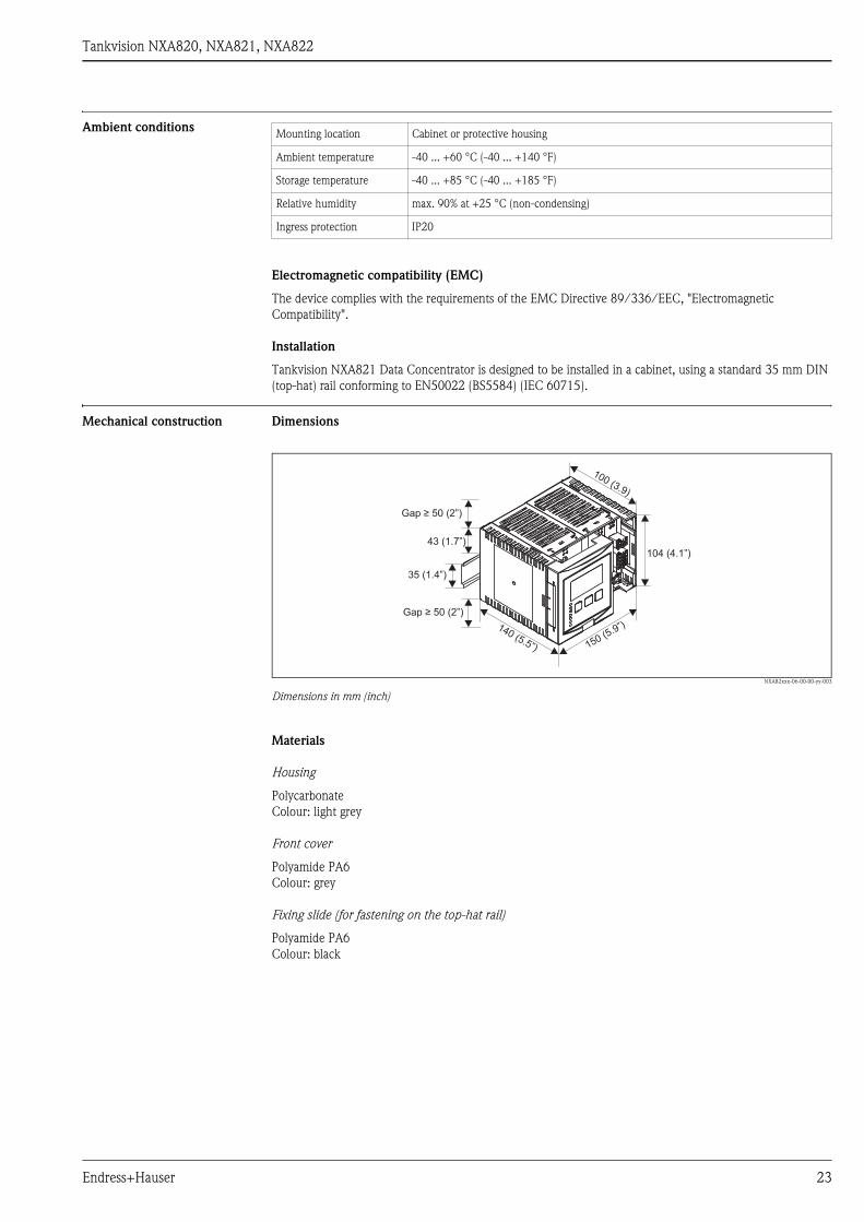
Ambient conditions
Electromagnetic compatibility (EMC)
The device complies with the requirements of the EMC Directive 89/336/EEC, "Electromagnetic
Compatibility".
Installation
Tankvision NXA821 Data Concentrator is designed to be installed in a cabinet, using a standard 35 mm DIN
(top-hat) rail conforming to EN50022 (BS5584) (IEC 60715).
Mechanical construction Dimensions
NXA82xxx-06-00-00-yy-003
Dimensions in mm (inch)
Materials
Housing
Polycarbonate
Colour: light grey
Front cover
Polyamide PA6
Colour: grey
Fixing slide (for fastening on the top-hat rail)
Polyamide PA6
Colour: black
Mounting location Cabinet or protective housing
Ambient temperature -40 ... +60 °C (-40 ... +140 °F)
Storage temperature -40 ... +85 °C (-40 ... +185 °F)
Relative humidity max. 90% at +25 °C (non-condensing)
Ingress protection IP20
43 (1.7”)
35 (1.4”)
104 (4.1”)
150 (5.9”)140 (5.5”)
100 (3.9)
Gap ≥ 50 (2”)
Gap ≥ 50 (2”)
Endress+Hauser 23
Tankvision NXA820, NXA821, NXA822
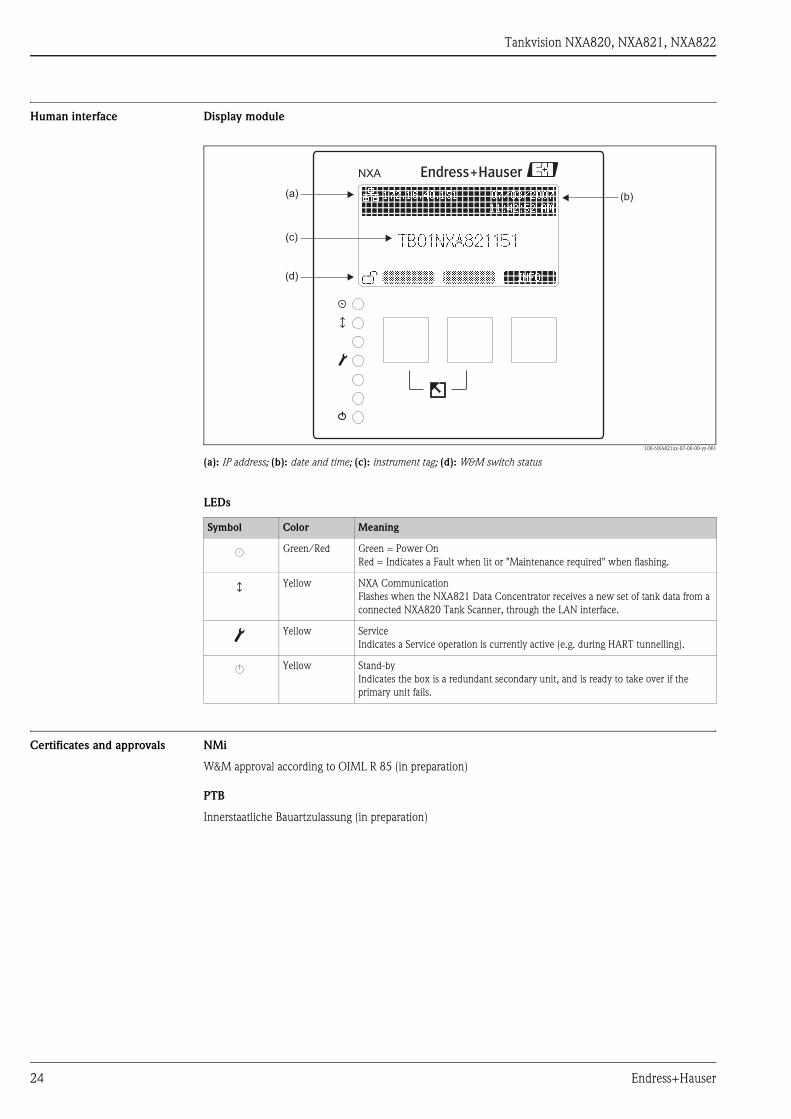
Human interface Display module
L00-NXA821xx-07-00-00-yy-001
(a): IP address; (b): date and time; (c): instrument tag; (d): W&M switch status
LEDs
Certificates and approvals NMi
W&M approval according to OIML R 85 (in preparation)
PTB
Innerstaatliche Bauartzulassung (in preparation)
NXA
(a)
(c)
(b)
(d)
Symbol Color Meaning
Green/Red Green = Power On
Red = Indicates a Fault when lit or "Maintenance required" when flashing.
Yellow NXA Communication
Flashes when the NXA821 Data Concentrator receives a new set of tank data from a
connected NXA820 Tank Scanner, through the LAN interface.
Yellow Service
Indicates a Service operation is currently active (e.g. during HART tunnelling).
Yellow Stand-by
Indicates the box is a redundant secondary unit, and is ready to take over if the
primary unit fails.
24 Endress+Hauser

Tankvision NXA820, NXA821, NXA822
Ordering information
NXA821010 Approval
A Non-Hazardous area
030 Power supply
1 90-250 VAC 50/60Hz
2 10.5-32 VDC
9 Special version, to be specified
050 Data Archive Memory Size
D 1GB; 15 parameters/min; 90 days
Y Special version, to be specified
060 Local Operation
1 status display
9 Special version, to be specified
070 Operation Language
A English
Y Special version, to be specified
080 Housing
1 DIN rail mounting PBT, IP20
9 Special version, to be specified
090 Redundancy
1 w/o
2 activated (in preparation)
9 Special version, to be specified
100 Custody Transfer Approval
0 not selected
1 NMI + PTB type (in preparation)
9 Special version, to be specified
110 Additional Option
A Basic version
Y Special version, to be specified
NXA821 - complete product designation
Endress+Hauser 25

Tankvision NXA820, NXA821, NXA822
26 Endress+Hauser

Tankvision NXA820, NXA821, NXA822
Tankvision NXA822 (Host Link)
Function • The Host Link NXA822 collects data from all Tank Scanners NXA820 on a network and transfers them to
the host system.
• The MODBUS option supports serial EIA-232(RS) and EIA-485(RS), as well as MODBUS TCP/IP. The
NXA822 is configured as a MODBUS slave. Supported functions are:
– Coil Status (#01)
– Holding Registers (#03)
– Input Registers (#04)
– Write Modbus Values (#06)
• The MODBUS register map can be described via XML files and so easily adapted to individual MODBUS
master requirements.
Number of tanks • 225 tanks4) can be allocated to each Host Link NXA822. Each of these tanks must have been allocated to a
Tank Scanner NXA820 before.
If more than 225 tanks are to be integrated in the system, multiple Host Links NXA822 have to be used.
• Tanks from up to 15 different Tank Scanners NXA820 can be integrated in this way5) .
If more than 15 Tank Scanners NXA820 are involved , multiple Host Links NXA822 have to be used.
LAN connections System LAN port
100 BASE-TX, Full/Half Duplex, 100 Mbit, Shielded RJ45 connector
Connects the NXA822 Host Link to the Local Area Network (LAN)
SyncLink LAN port (in preparation)
100 BASE-TX, Full/Half Duplex, 100 Mbit, Shielded RJ45 connector
Connects the NXA822 Host Link (e.g. primary) to an optional redundant unit (e.g secondary), to make sure
the two devices remain synchronized with each other. If the primary unit fails, the secondary NXA822 Host
Link takes over operation without system interruption.
Service LAN port
100 BASE-TX, Full/Half Duplex, 100 Mbit, Shielded RJ45 connector
Connects the NXA822 Host Link to a local computer only for local commissioning and service operations. The
computer does not become part of the local area network the NXA822 Host Link is connected to through the
System LAN port.
This port has a fixed IP address and can also provide the connected computer automatically with a compatible
IP address using a DHCP server built into the NXA822 Host Link. For this automatic IP function to work the
computer must be set to obtain its IP address using a DHCP server.
! Note!
All LAN ports support Auto-MDIX, this system automatically detects the type of cable connected (either
straight or crossed) and adjusts itself to match. With this feature you do not need to obtain special crossed cables
to interconnect Tankvision components.
Output NXA822 NXA Status Relay
• potential free relay, SPDT
• normally-closed when NXA is operating normally, open when NXA is powered off or fault status exists
• switching power:
– 25 VDC, 100 W
– 250 VAC, 4 A, 1000VA
Host connection
• EIA-232(RS)
• EIA-485(RS)
• TCP-IP on System LAN port
4) standard: 45 tanks;
on request: more than 45 tanks; up to 225 tanks
5) standard: 4 Tank Scanners;
on request: more than 4 Tank Scanners; up to 15 Tank Scanners
Endress+Hauser 27
Tankvision NXA820, NXA821, NXA822
Power supply
Galvanic isolation
The following terminals are galvanically isolated from each other:
• Alarm relay output
• LAN interfaces
• Host connection
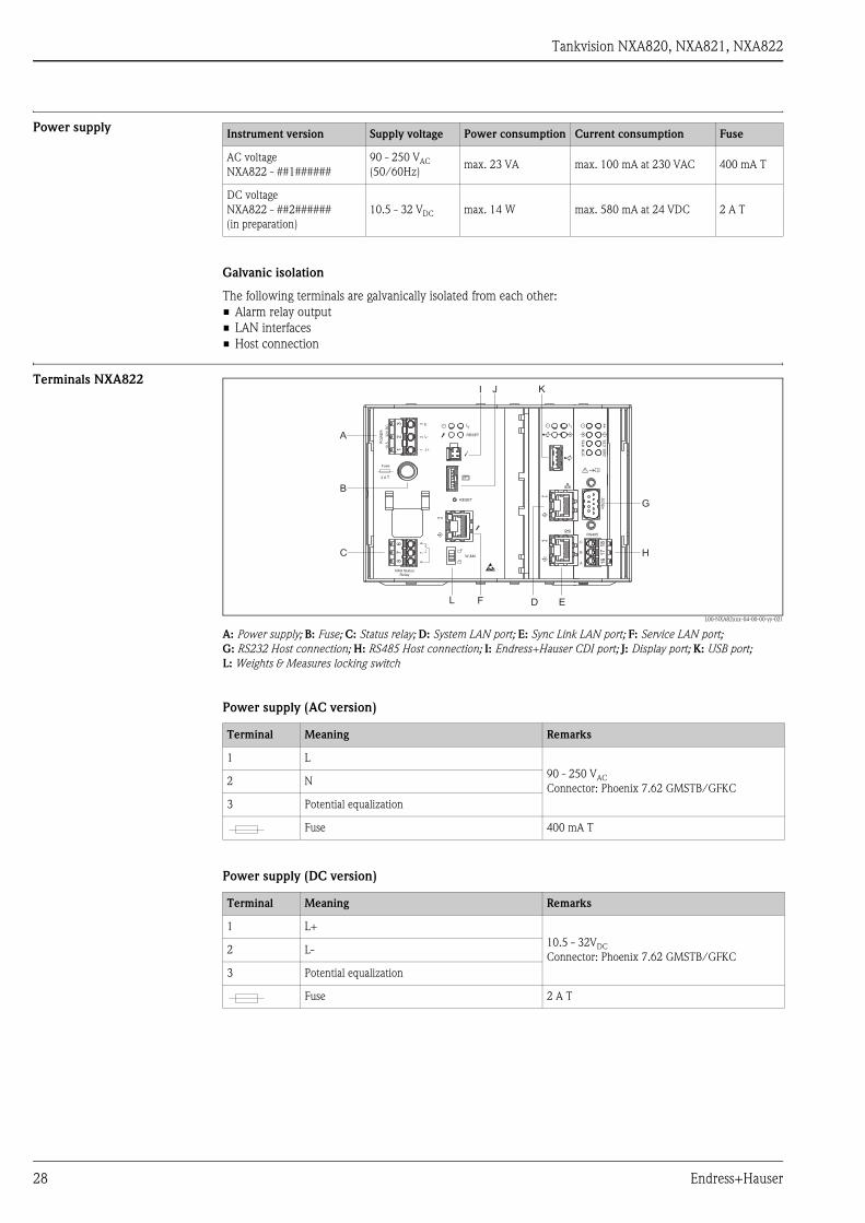
Terminals NXA822
L00-NXA82xxx-04-00-00-yy-021
A: Power supply; B: Fuse; C: Status relay; D: System LAN port; E: Sync Link LAN port; F: Service LAN port;
G: RS232 Host connection; H: RS485 Host connection; I: Endress+Hauser CDI port; J: Display port; K: USB port;
L: Weights & Measures locking switch
Power supply (AC version)
Power supply (DC version)
Instrument version Supply voltage Power consumption Current consumption Fuse
AC voltage
NXA822 - ##1######
90 - 250 VAC
(50/60Hz)max. 23 VA max. 100 mA at 230 VAC 400 mA T
DC voltage
NXA822 - ##2######
(in preparation)
10.5 - 32 VDC max. 14 W max. 580 mA at 24 VDC 2 A T
23
16
78
W &M
RESET
RESET
NXA StatusRelay
E
L+
L-
67
83
21
Fuse
PO
WE
R
10,5
...32V
DC
2 A T
DT
R
DS
RC
TS
RT
S
RS485
RS
23
2
C
B
A
18
17
16
A
B
C
D EF
G
H
I J K
L
Terminal Meaning Remarks
1 L
90 - 250 VAC
Connector: Phoenix 7.62 GMSTB/GFKC2 N
3 Potential equalization
Fuse 400 mA T
Terminal Meaning Remarks
1 L+
10.5 - 32VDC
Connector: Phoenix 7.62 GMSTB/GFKC2 L-
3 Potential equalization
Fuse 2 A T
28 Endress+Hauser
Tankvision NXA820, NXA821, NXA822
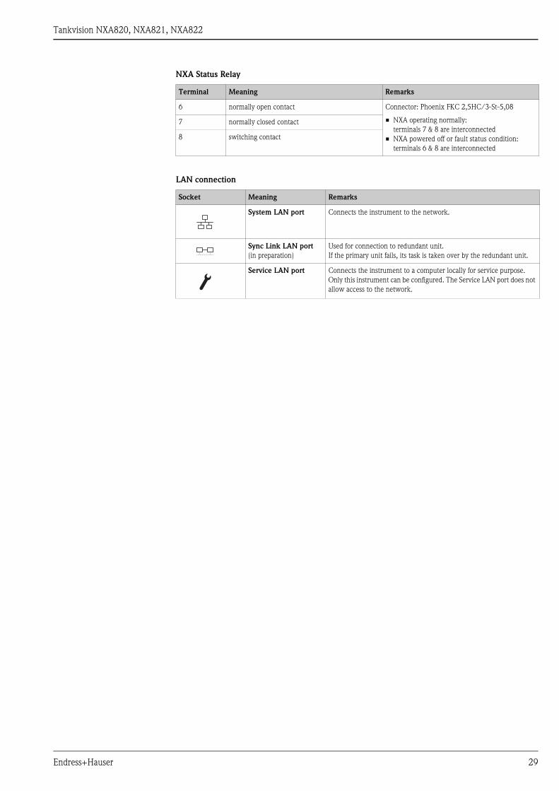
NXA Status Relay
LAN connection
Terminal Meaning Remarks
6 normally open contact Connector: Phoenix FKC 2,5HC/3-St-5,08
• NXA operating normally:
terminals 7 & 8 are interconnected
• NXA powered off or fault status condition:
terminals 6 & 8 are interconnected
7 normally closed contact
8 switching contact
Socket Meaning Remarks
System LAN port Connects the instrument to the network.
Sync Link LAN port
(in preparation)
Used for connection to redundant unit.
If the primary unit fails, its task is taken over by the redundant unit.
Service LAN port Connects the instrument to a computer locally for service purpose.
Only this instrument can be configured. The Service LAN port does not
allow access to the network.
Endress+Hauser 29

Tankvision NXA820, NXA821, NXA822
Field connection: MODBUS Serial, EIA/TIA-232 (RS232)
The NXA822 Data Concentrator is defined as a Data Terminal Equipment (DTE) device, and provides EIA/
TIA-232 (RS232) interface through a male DB9 connector whose pin out complies with the EIA/TIA-574
standard:
Definition
EIA/TIA-232 (RS232) is a voltage mode digital communication using up to ±12 VDC, and requires a variety of
signals depending on the operating mode (software selectable):
RS-232 Cable Specification
Pin RS232 Name Remarks
1 CD Carrier Detect Signal from connected device
2 RxD Receive Data Signal from connected device
3 TxD Transmit Data Signal to connected device
4 DTR Data Terminal Ready Signal to connected device
5 G Signal Ground Common connection
6 DSR Data Set Ready Signal from connected device
7 RTS Request To Send Signal to connected device
8 CTS Clear To Send Signal from connected device
9 RI Ring Indicator Signal from connected device
Case Shield Shield
Signal Basic RS232 Fully RS232 with
Hardware Handshaking
(in preparation)
Remarks
Shield Required Required Copper braided or combined foil and braided
shielding
G Required Required
RxD Required Required
TxD Required Required
RTS Required Null Modem connection, these two pins can be
linked togetherCTS Required
DTR Required Null Modem connection, these three pins can be
linked togetherDSR Required
CD Required
RI Optional Not required
Cable capacitance ≤ 50 pF/m
Core cross-section ≥ 0.34 mm2, corresponds to AWG 22, multi-strand cable is preferred
Cable type Single cable or twisted pair
Cable resistance ≤ 110 Ω/km
Signal damping Max. 9 dB over the entire length of the cable cross-section
Shielding Copper braided shielding or combined foil and braided shielding
30 Endress+Hauser
Tankvision NXA820, NXA821, NXA822
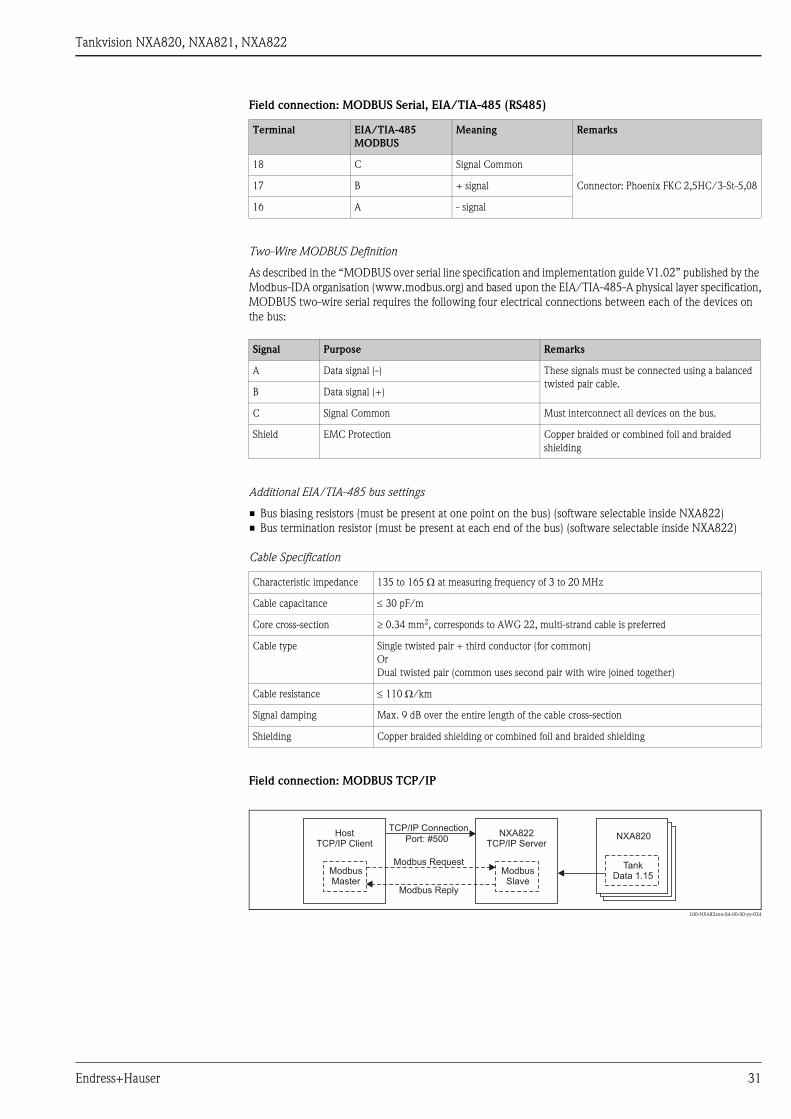
Field connection: MODBUS Serial, EIA/TIA-485 (RS485)
Two-Wire MODBUS Definition
As described in the “MODBUS over serial line specification and implementation guide V1.02” published by the
Modbus-IDA organisation (www.modbus.org) and based upon the EIA/TIA-485-A physical layer specification,
MODBUS two-wire serial requires the following four electrical connections between each of the devices on
the bus:
Additional EIA/TIA-485 bus settings
• Bus biasing resistors (must be present at one point on the bus) (software selectable inside NXA822)
• Bus termination resistor (must be present at each end of the bus) (software selectable inside NXA822)
Cable Specification
Field connection: MODBUS TCP/IP
L00-NXA82xxx-04-00-00-yy-024
Terminal EIA/TIA-485
MODBUS
Meaning Remarks
18 C Signal Common
Connector: Phoenix FKC 2,5HC/3-St-5,0817 B + signal
16 A - signal
Signal Purpose Remarks
A Data signal (-) These signals must be connected using a balanced
twisted pair cable.B Data signal (+)
C Signal Common Must interconnect all devices on the bus.
Shield EMC Protection Copper braided or combined foil and braided
shielding
Characteristic impedance 135 to 165 Ω at measuring frequency of 3 to 20 MHz
Cable capacitance ≤ 30 pF/m
Core cross-section ≥ 0.34 mm2, corresponds to AWG 22, multi-strand cable is preferred
Cable type Single twisted pair + third conductor (for common)
Or
Dual twisted pair (common uses second pair with wire joined together)
Cable resistance ≤ 110 Ω/km
Signal damping Max. 9 dB over the entire length of the cable cross-section
Shielding Copper braided shielding or combined foil and braided shielding
HostTCP/IP Client
ModbusMaster
NXA822TCP/IP Server
ModbusSlave
NXA820
TankData 1.15
TCP/IP Connection
Port: #500
Modbus Request
Modbus Reply
Endress+Hauser 31

Tankvision NXA820, NXA821, NXA822
LEDs
Symbol Color Meaning
Green Power On
Yellow Stand-by
Indicates the box is a redundant secondary unit, and is ready to take over if the
primary unit fails.
Red Fault
Indicates a Fault when lit or "Maintenance required" when flashing
Yellow Slave Communication (on base unit). Flashes when the NXA822 Host Link
completes a successful fieldbus communication cycle (e.g. Receives a request and
sends a reply).
Yellow NXA Communication (on local display)
Flashes when the NXA822 Host Link receives a new set of tank data from a
connected NXA820 Tank Scanner, through the LAN interface.
Yellow Fieldbus Rx
Flashes to indicate data bits are being received from the connected field devices.
Yellow Fieldbus Tx
Flashes to indicate data bits are being sent to the connected field devices.
RTS Yellow Request to Send
Flashes to indicate the RTS signal is being sent to the connected field device, only
used when Full RS-232 mode is selected, otherwise off.
CTS Yellow Clear to Send
Flashes to indicate the CTS signal is being received from the connected field device,
only used when Full RS-232 mode is selected, otherwise off.
DTR Yellow Data Terminal Ready
Flashes to indicate the DTR signal is being sent to the connected field device, only
used when Full RS-232 mode is selected, otherwise off.
DSR Yellow Data Set Ready
Flashes to indicate the DSR signal is being received from the connected field device,
only used when Full RS-232 mode is selected, otherwise off.
Data Transfer
Green Indicates data is being transferred on the LAN interface.
Yellow Indicates data is being transferred on the USB interface.
Linked
Indicates that the LAN cable is both connected and functioning.
Yellow USB active (for future enhancements)
When lit the connect USB device has been detected and is in use, do not remove the
device while this LED is lit.
Yellow Service
Indicates a Service operation is currently active (e.g. during HART tunnelling).
32 Endress+Hauser
Tankvision NXA820, NXA821, NXA822
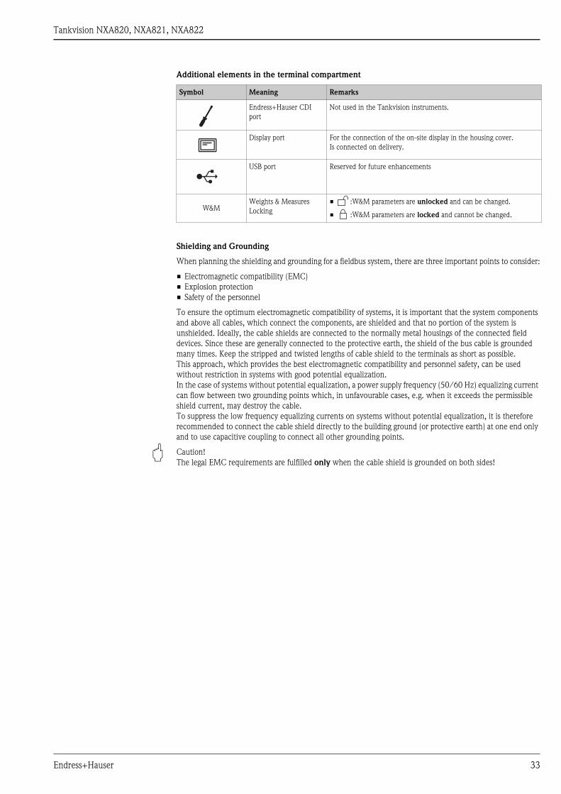
Additional elements in the terminal compartment
Shielding and Grounding
When planning the shielding and grounding for a fieldbus system, there are three important points to consider:
• Electromagnetic compatibility (EMC)
• Explosion protection
• Safety of the personnel
To ensure the optimum electromagnetic compatibility of systems, it is important that the system components
and above all cables, which connect the components, are shielded and that no portion of the system is
unshielded. Ideally, the cable shields are connected to the normally metal housings of the connected field
devices. Since these are generally connected to the protective earth, the shield of the bus cable is grounded
many times. Keep the stripped and twisted lengths of cable shield to the terminals as short as possible.
This approach, which provides the best electromagnetic compatibility and personnel safety, can be used
without restriction in systems with good potential equalization.
In the case of systems without potential equalization, a power supply frequency (50/60 Hz) equalizing current
can flow between two grounding points which, in unfavourable cases, e.g. when it exceeds the permissible
shield current, may destroy the cable.
To suppress the low frequency equalizing currents on systems without potential equalization, it is therefore
recommended to connect the cable shield directly to the building ground (or protective earth) at one end only
and to use capacitive coupling to connect all other grounding points.
" Caution!
The legal EMC requirements are fulfilled only when the cable shield is grounded on both sides!
Symbol Meaning Remarks
Endress+Hauser CDI
port
Not used in the Tankvision instruments.
Display port For the connection of the on-site display in the housing cover.
Is connected on delivery.
USB port Reserved for future enhancements
W&MWeights & Measures
Locking
• :W&M parameters are unlocked and can be changed.
• :W&M parameters are locked and cannot be changed.
Endress+Hauser 33
Tankvision NXA820, NXA821, NXA822
Ambient conditions
Electromagnetic compatibility (EMC)
The device complies with the requirements of the EMC Directive 89/336/EEC, "Electromagnetic
Compatibility".
Installation
Tankvision NXA822 Host Link is designed to be installed in a cabinet, using a standard 35 mm DIN (top-hat)
rail conforming to EN50022 (BS5584) (IEC 60715).
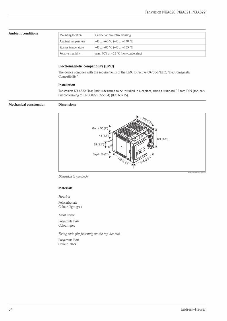
Mechanical construction Dimensions
NXA82xxx-06-00-00-yy-003
Dimension in mm (inch)
Materials
Housing
Polycarbonate
Colour: light grey
Front cover
Polyamide PA6
Colour: grey
Fixing slide (for fastening on the top-hat rail)
Polyamide PA6
Colour: black
Mounting location Cabinet or protective housing
Ambient temperature -40 ... +60 °C (-40 ... +140 °F)
Storage temperature -40 ... +85 °C (-40 ... +185 °F)
Relative humidity max. 90% at +25 °C (non-condensing)
43 (1.7”)
35 (1.4”)
104 (4.1”)
150 (5.9”)140 (5.5”)
100 (3.9)
Gap ≥ 50 (2”)
Gap ≥ 50 (2”)
34 Endress+Hauser
Tankvision NXA820, NXA821, NXA822
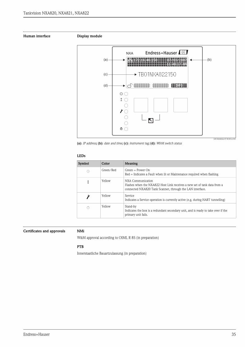
Human interface Display module
L00-NXA822xx-07-00-00-yy-001
(a): IP address; (b): date and time; (c): instrument tag; (d): W&M switch status
LEDs
Certificates and approvals NMi
W&M approval according to OIML R 85 (in preparation)
PTB
Innerstaatliche Bauartzulassung (in preparation)
NXA
(a)
(c)
(b)
(d)
Symbol Color Meaning
Green/Red Green = Power On
Red = Indicates a Fault when lit or Maintenance required when flashing
Yellow NXA Communication
Flashes when the NXA822 Host Link receives a new set of tank data from a
connected NXA820 Tank Scanner, through the LAN interface.
Yellow Service
Indicates a Service operation is currently active (e.g. during HART tunnelling)
Yellow Stand-by
Indicates the box is a redundant secondary unit, and is ready to take over if the
primary unit fails.
Endress+Hauser 35
Tankvision NXA820, NXA821, NXA822
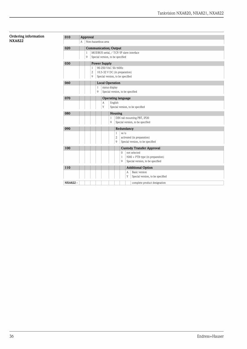
Ordering information
NXA822010 Approval
A Non-hazardous area
020 Communication; Output
1 MODBUS serial, / TCP/IP slave interface
9 Special version, to be specified
030 Power Supply
1 90-250 VAC 50/60Hz
2 10.5-32 V DC (in preparation)
9 Special version, to be specified
060 Local Operation
1 status display
9 Special version, to be specified
070 Operating language
A English
Y Special version, to be specified
080 Housing
1 DIN rail mounting PBT, IP20
9 Special version, to be specified
090 Redundancy
1 w/o
2 activated (in preparation)
9 Special version, to be specified
100 Custody Transfer Approval
0 not selected
1 NMI + PTB type (in preparation)
9 Special version, to be specified
110 Additional Option
A Basic version
Y Special version, to be specified
NXA822 - complete product designation
36 Endress+Hauser

Tankvision NXA820, NXA821, NXA822
Human interface
Operating concept Tankvision is operated by a standard web browser (e.g. Microsoft Internet Explorer).
The Tankvision components contain predefined operating pages. If required, they can be adjusted by the user.
Languages The operating pages are available in the following languages:
• English
• other languages in preparation
System requirements
of user PC
Hardware
Software
Network
Network switches must always be used to interconnect Tankvision components (Network hubs must never
be used).
Only use screened Category 5 (or higher) cables.
" Caution!
The legal EMC requirements are fulfilled only when screened LAN cable is used and the cable screen is
properly terminated to screened RJ45 connectors.
" Caution!
Most commercial and IT infrastructure networking switches (and components) are not designed to be used
within harsh environments (e.g. temperatures below +5ºC, dusty or with high levels of EMC or electrical
noise), it is therefore recommended that only networking components specifically designed for industrial
control purposes be used within the control room (or control cabinet) environment as part of the Tankvision
system.
CPU min. 1 GHz, P4
RAM 512 MB
Screen resolution min. 1024x768; recommended 1280x1024
Operating System Microsoft Windows 2000 / XP
Web Browser Microsoft Internet Explorer 6
Java Runtime Environment 1.5.0-upt.07
Endress+Hauser 37
Tankvision NXA820, NXA821, NXA822
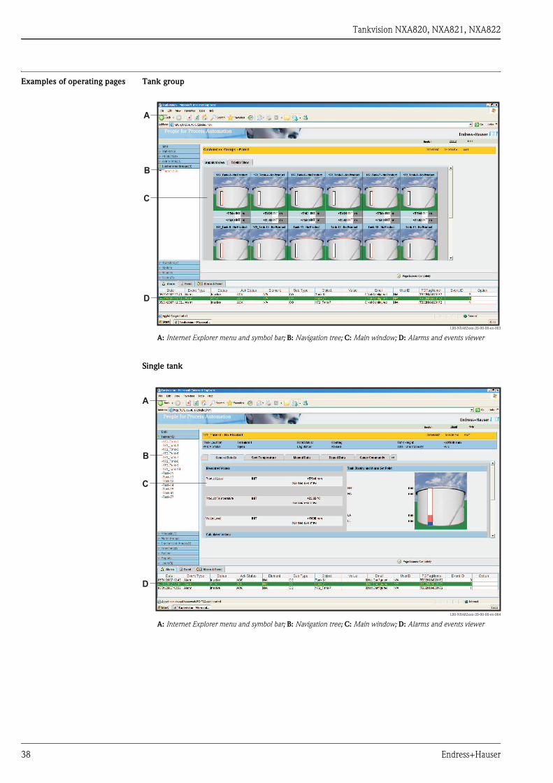
Examples of operating pages Tank group
L00-NXA82xxx-20-00-00-en-003
A: Internet Explorer menu and symbol bar; B: Navigation tree; C: Main window; D: Alarms and events viewer
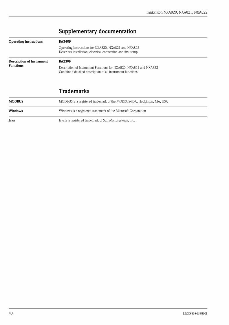
Single tank
L00-NXA82xxx-20-00-00-en-004
A: Internet Explorer menu and symbol bar; B: Navigation tree; C: Main window; D: Alarms and events viewer
A
B
C
D
A
B
C
D
38 Endress+Hauser

Tankvision NXA820, NXA821, NXA822
Alarm Popup Agent
L00-NXA82xxx-20-00-00-en-005
Endress+Hauser 39
Tankvision NXA820, NXA821, NXA822
Supplementary documentation
Operating Instructions BA340F
Operating Instructions for NXA820, NXA821 and NXA822
Describes installation, electrical connection and first setup.
Description of Instrument
Functions
BA239F
Description of Instrument Functions for NXA820, NXA821 and NXA822
Contains a detailed description of all instrument functions.
Trademarks
MODBUS MODBUS is a registered trademark of the MODBUS-IDA, Hopkinton, MA, USA
Windows Windows is a registered trademark of the Microsoft Corporation
Java Java is a registered trademark of Sun Microsystems, Inc.
40 Endress+Hauser

Tankvision NXA820, NXA821, NXA822
Endress+Hauser 41

Tankvision NXA820, NXA821, NXA822
42 Endress+Hauser

Tankvision NXA820, NXA821, NXA822
Endress+Hauser 43

In
EnInKa41Sw
TeFawwinf
struments International
dress+Hauserstruments International AGegenstrasse 253 Reinachitzerland
l. +41 61 715 81 00x +41 61 715 25 00
TI419F/00/en/05.08
FM+SGML 6.0 ProMoDo