
Technical Information • Installation...
16
Technical Information • Installation Instructions R1 Oil GB Edition June 2001 Technical changes in the sense of product improvement reserved!
Transcript of Technical Information • Installation...
Technical Information • Installation Instructions
R1Oil
GB
Edition June 2001Technical changes in the sense of product improvement reserved!
Page 2
G. 1
5.06
.11
ContentsOverview
ContentsPage
Overview ContentsGeneral information/Safety information
22
Installation Installation of flange and burnerService positionConnecting the electrical supplyOil connectionOil pump
33334
Function Checking control box function - Flame controlMeasurement of photo-electric current (MZ 770)
55
Start-up Nozzle selectionInsert nozzleAdjustment of the ignition electrodesAir adjustmentStart-up (R1-L / R1-V-L)
66666
Design Design -L (actuator SA2-F)Design -V (with oil preheater)Design -B (with service hour meter)Design -OC (with Oil Control)
777
7/8Service information Adjustment boiler - burner
Connection of the chimneyFlue gas thermometerExplosion drawing and parts list R1-V-LWiring diagrams and legendFault diagnosisAdjustment table/ Declaration of conformityNotesTechnical dataWorking rangesBoiler connection measuresBurner construction measures
999
1011/12
13141516161616
General informationGlERSCH oil burners R1 are the resultof many years of research and de-velopment work. Whilst our commit-ment is to supply you with the finestpossible products, please note that forthe best results, these oil burnersmust be properly calibrated duringcommissioning to meet local site con-ditions.Care and accuracy when setting theburner will result in higher efficiencyand lower fuel costs, to the satisfactionof our mutual customer.To achieve low-emitting and economiccombustion, the following informationmust absolutely be observed!Tested and licensed according toDIN EN 267 for fuel oil EL according toDIN 51603.
Safety instructionsObserve the technical rules as well asthe legal prescriptions and those ofthe building supervision when instal-ling and operating the plant.Installation, oil and flue gas connec-tion, initial start-up, electrical connec-tion as well as maintenance andoverhaul work may only be performedby specialists.For connecting the electrical supply,the VDE or ÖVE regulations and theregulations of the responsible electricsupply company must be considered.Work at electrical equipment may onlybe performed by a specialist in accor-dance with the relevant VDE and ÖVEprescriptions.
Danger of injuries at rotating fan onstart-up in service position.
Maintenance§ 9 of the heating installation decreerequires regular maintenance of theplant to ensure a reliable and safefunction of the appliance.The appliance must be maintained yearly.We recommend to conclude a mainte-nance contract with admitted specia-lists.
Key for code designation:-B = with service hour meter-L = with air damper-OC = with Oil-Control-V = with oil preheater-WLE = for warm air heating
with DKW 972 for R1-L
Page 3
G. 1
5.06
.11
Installation of flange and burner
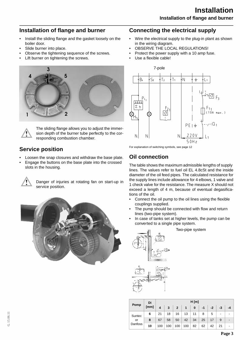
Installation of flange and burner• Install the sliding flange and the gasket loosely on the
boiler door.• Slide burner into place.• Observe the tightening sequence of the screws.• Lift burner on tightening the screws.
The sliding flange allows you to adjust the immer-sion depth of the burner tube perfectly to the cor-responding combustion chamber.
Service position• Loosen the snap closures and withdraw the base plate.• Engage the buttons on the base plate into the crossed
slots in the housing.
Danger of injuries at rotating fan on start-up inservice position.
Connecting the electrical supply• Wire the electrical supply to the plug-in plant as shown
in the wiring diagram.• OBSERVE THE LOCAL REGULATIONS!• Protect the power supply with a 10 amp fuse.• Use a flexible cable!
For explanation of switching symbols, see page 12
Oil connectionThe table shows the maximum admissible lengths of supply lines. The values refer to fuel oil EL 4.8cSt and the insidediameter of the oil feed pipes. The calculated resistance forthe supply lines include allowance for 4 elbows, 1 valve and1 check valve for the resistance. The measure X should notexceed a length of 4 m, because of eventual degasifica-tions of the oil.• Connect the oil pump to the oil lines using the flexible
couplings supplied.• The pump should be connected with flow and return
lines (two-pipe system).• In case of tanks set at higher levels, the pump can be
converted to a single pipe system.
PompDi
[mm]
H [m]
4 3 2 1 0 -1 -2 -3 -4
Suntec or
Danfoss
6 21 18 16 13 11 8 5 - -
8 67 58 50 42 34 25 17 9 -
10 100 100 100 100 82 62 42 21 -
7-pole
Two-pipe system
Installation
Page 4
G. 1
5.06
.11
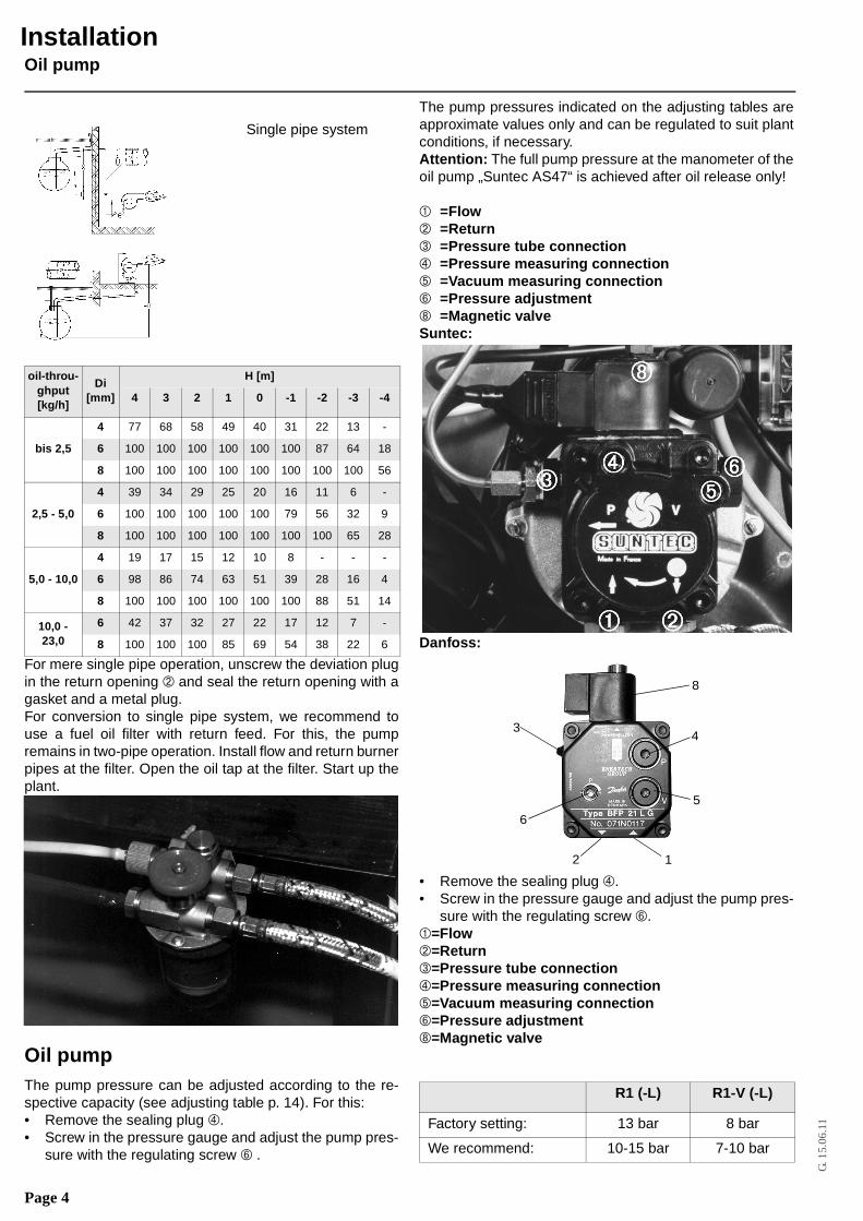
Oil pump
For mere single pipe operation, unscrew the deviation plugin the return opening Á and seal the return opening with agasket and a metal plug. For conversion to single pipe system, we recommend touse a fuel oil filter with return feed. For this, the pumpremains in two-pipe operation. Install flow and return burnerpipes at the filter. Open the oil tap at the filter. Start up theplant.
Oil pumpThe pump pressure can be adjusted according to the re-spective capacity (see adjusting table p. 14). For this:• Remove the sealing plug Ã.• Screw in the pressure gauge and adjust the pump pres-
sure with the regulating screw Å .
The pump pressures indicated on the adjusting tables areapproximate values only and can be regulated to suit plantconditions, if necessary.Attention: The full pump pressure at the manometer of theoil pump „Suntec AS47“ is achieved after oil release only!
À =FlowÁ =Return =Pressure tube connectionà =Pressure measuring connectionÄ =Vacuum measuring connectionÅ =Pressure adjustmentÇ =Magnetic valveSuntec:
Danfoss:
• Remove the sealing plug Ã. • Screw in the pressure gauge and adjust the pump pres-
sure with the regulating screw Å.À=FlowÁ=ReturnÂ=Pressure tube connectionÃ=Pressure measuring connectionÄ=Vacuum measuring connectionÅ=Pressure adjustmentÇ=Magnetic valve
oil-throu-ghput[kg/h]
Di[mm]
H [m]
4 3 2 1 0 -1 -2 -3 -4
bis 2,5
4 77 68 58 49 40 31 22 13 -
6 100 100 100 100 100 100 87 64 18
8 100 100 100 100 100 100 100 100 56
2,5 - 5,0
4 39 34 29 25 20 16 11 6 -
6 100 100 100 100 100 79 56 32 9
8 100 100 100 100 100 100 100 65 28
5,0 - 10,0
4 19 17 15 12 10 8 - - -
6 98 86 74 63 51 39 28 16 4
8 100 100 100 100 100 100 88 51 14
10,0 - 23,0
6 42 37 32 27 22 17 12 7 -
8 100 100 100 85 69 54 38 22 6
Single pipe system
R1 (-L) R1-V (-L)
Factory setting: 13 bar 8 bar
We recommend: 10-15 bar 7-10 bar
12
3
6
8
4
5
Installation
Page 5
G. 1
5.06
.11
Checking control box function - Flame control
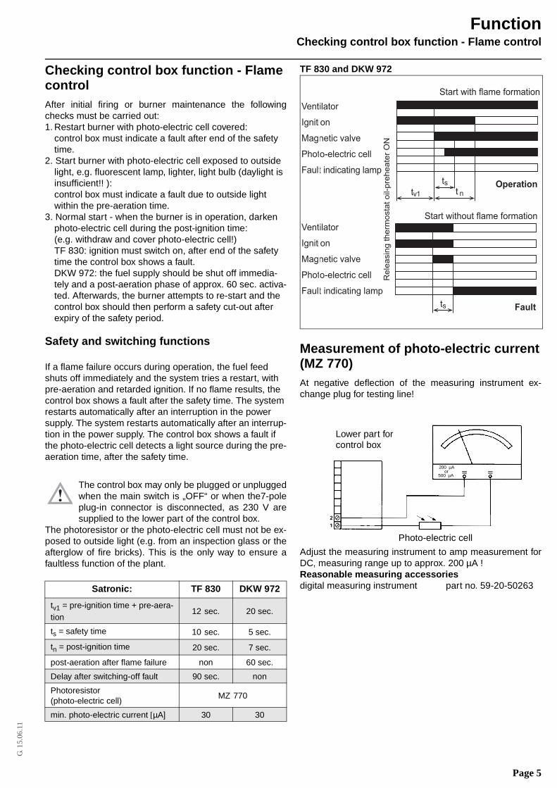
Checking control box function - Flame controlAfter initial firing or burner maintenance the followingchecks must be carried out:1. Restart burner with photo-electric cell covered:
control box must indicate a fault after end of the safety time.
2. Start burner with photo-electric cell exposed to outside light, e.g. fluorescent lamp, lighter, light bulb (daylight is insufficient!! ):control box must indicate a fault due to outside light within the pre-aeration time.
3. Normal start - when the burner is in operation, darken photo-electric cell during the post-ignition time:(e.g. withdraw and cover photo-electric cell!)TF 830: ignition must switch on, after end of the safetytime the control box shows a fault.DKW 972: the fuel supply should be shut off immedia-tely and a post-aeration phase of approx. 60 sec. activa-ted. Afterwards, the burner attempts to re-start and the control box should then perform a safety cut-out after expiry of the safety period.
Safety and switching functions
If a flame failure occurs during operation, the fuel feed shuts off immediately and the system tries a restart, with pre-aeration and retarded ignition. If no flame results, the control box shows a fault after the safety time. The system restarts automatically after an interruption in the power supply. The system restarts automatically after an interrup-tion in the power supply. The control box shows a fault if the photo-electric cell detects a light source during the pre-aeration time, after the safety time.
The control box may only be plugged or unpluggedwhen the main switch is „OFF“ or when the7-poleplug-in connector is disconnected, as 230 V aresupplied to the lower part of the control box.
The photoresistor or the photo-electric cell must not be ex-posed to outside light (e.g. from an inspection glass or theafterglow of fire bricks). This is the only way to ensure afaultless function of the plant.
TF 830 and DKW 972
Measurement of photo-electric current(MZ 770)At negative deflection of the measuring instrument ex-change plug for testing line!
Adjust the measuring instrument to amp measurement forDC, measuring range up to approx. 200 µA !Reasonable measuring accessoriesdigital measuring instrument part no. 59-20-50263Satronic: TF 830 DKW 972
tv1 = pre-ignition time + pre-aera-tion
12 sec. 20 sec.
ts = safety time 10 sec. 5 sec.
tn = post-ignition time 20 sec. 7 sec.
post-aeration after flame failure non 60 sec.
Delay after switching-off fault 90 sec. non
Photoresistor (photo-electric cell)
MZ 770
min. photo-electric current [µA] 30 30
Start with flame formation
Re
lea
sin
g t
he
rmo
sta
t o
il-p
reh
ea
ter
ON
Ventilator
Ignition
Magnetic valve
Photo-electric cell
Fault indicating lamp
ts Fault
Ventilator
Ignition
Magnetic valve
Photo-electric cell
Fault indicating lamp
tv1
tst n
Operation
Start without flame formation
TF830 / MMO 872
Photo-electric cell
Lower part forcontrol box
200 µAor
500 µA
Function
Page 6
G. 1
5.06
.11
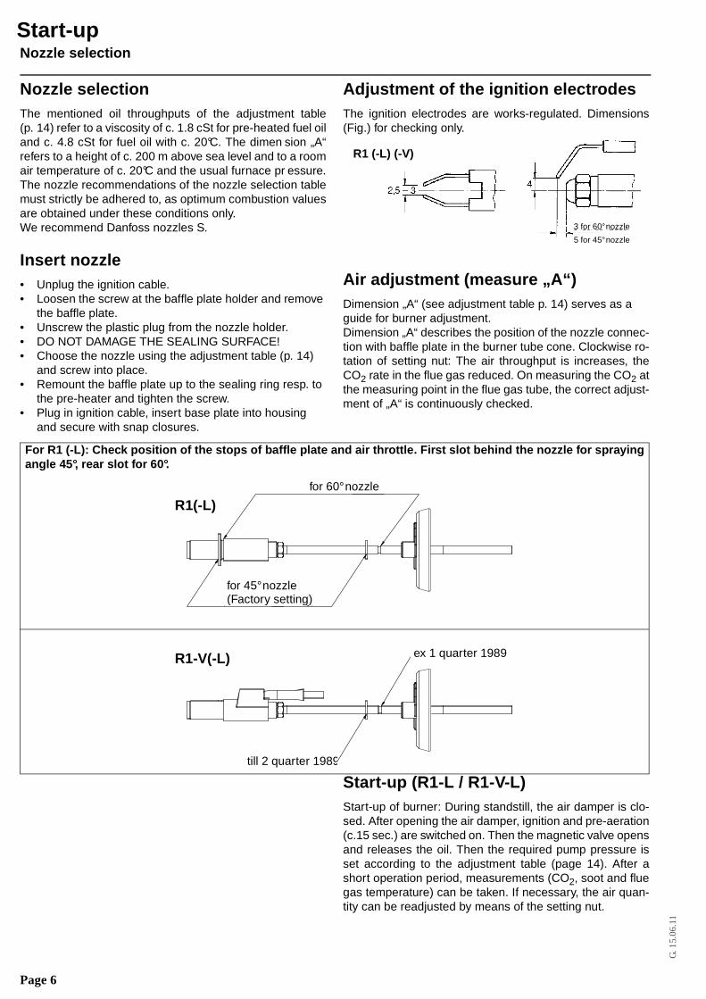
Nozzle selection
Nozzle selectionThe mentioned oil throughputs of the adjustment table(p. 14) refer to a viscosity of c. 1.8 cSt for pre-heated fuel oiland c. 4.8 cSt for fuel oil with c. 20°C. The dimen sion „A“refers to a height of c. 200 m above sea level and to a roomair temperature of c. 20°C and the usual furnace pr essure.The nozzle recommendations of the nozzle selection tablemust strictly be adhered to, as optimum combustion valuesare obtained under these conditions only.We recommend Danfoss nozzles S.
Insert nozzle• Unplug the ignition cable.• Loosen the screw at the baffle plate holder and remove
the baffle plate.• Unscrew the plastic plug from the nozzle holder.• DO NOT DAMAGE THE SEALING SURFACE!• Choose the nozzle using the adjustment table (p. 14)
and screw into place.• Remount the baffle plate up to the sealing ring resp. to
the pre-heater and tighten the screw.• Plug in ignition cable, insert base plate into housing
and secure with snap closures.
Adjustment of the ignition electrodesThe ignition electrodes are works-regulated. Dimensions(Fig.) for checking only.
Air adjustment (measure „A“)Dimension „A“ (see adjustment table p. 14) serves as a guide for burner adjustment.Dimension „A“ describes the position of the nozzle connec-tion with baffle plate in the burner tube cone. Clockwise ro-tation of setting nut: The air throughput is increases, theCO2 rate in the flue gas reduced. On measuring the CO2 atthe measuring point in the flue gas tube, the correct adjust-ment of „A“ is continuously checked.
Start-up (R1-L / R1-V-L)Start-up of burner: During standstill, the air damper is clo-sed. After opening the air damper, ignition and pre-aeration(c.15 sec.) are switched on. Then the magnetic valve opensand releases the oil. Then the required pump pressure isset according to the adjustment table (page 14). After ashort operation period, measurements (CO2, soot and fluegas temperature) can be taken. If necessary, the air quan-tity can be readjusted by means of the setting nut.
3 for 60° nozzle
5 for 45° nozzle
R1 (-L) (-V)
For R1 (-L): Check position of the stops of baffle plate and air throttle. First slot behind the nozzl e for sprayingangle 45°, rear slot for 60°.
R1(-L)
R1-V(-L)
for 60° nozzle
for 45° nozzle(Factory setting)
ex 1 quarter 1989
till 2 quarter 1989
Start-up
Page 7
G. 1
5.06
.11
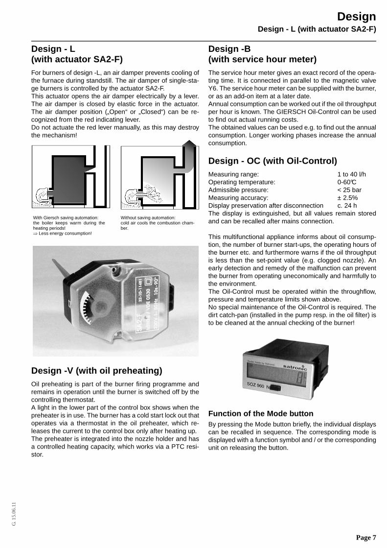
Design - L (with actuator SA2-F)
Design - L (with actuator SA2-F)For burners of design -L, an air damper prevents cooling ofthe furnace during standstill. The air damper of single-sta-ge burners is controlled by the actuator SA2-F.This actuator opens the air damper electrically by a lever.The air damper is closed by elastic force in the actuator.The air damper position („Open“ or „Closed“) can be re-cognized from the red indicating lever.Do not actuate the red lever manually, as this may destroythe mechanism!
Design -V (with oil preheating) Oil preheating is part of the burner firing programme andremains in operation until the burner is switched off by thecontrolling thermostat.A light in the lower part of the control box shows when thepreheater is in use. The burner has a cold start lock out thatoperates via a thermostat in the oil preheater, which re-leases the current to the control box only after heating up. The preheater is integrated into the nozzle holder and hasa controlled heating capacity, which works via a PTC resi-stor.
Design -B (with service hour meter)The service hour meter gives an exact record of the opera-ting time. It is connected in parallel to the magnetic valveY6. The service hour meter can be supplied with the burner,or as an add-on item at a later date.Annual consumption can be worked out if the oil throughputper hour is known. The GIERSCH Oil-Control can be usedto find out actual running costs.The obtained values can be used e.g. to find out the annualconsumption. Longer working phases increase the annualconsumption.
Design - OC (with Oil-Control)Measuring range: 1 to 40 l/hOperating temperature: 0-60°CAdmissible pressure: < 25 barMeasuring accuracy: ± 2.5%Display preservation after disconnection c. 24 hThe display is extinguished, but all values remain storedand can be recalled after mains connection.
This multifunctional appliance informs about oil consump-tion, the number of burner start-ups, the operating hours ofthe burner etc. and furthermore warns if the oil throughputis less than the set-point value (e.g. clogged nozzle). Anearly detection and remedy of the malfunction can preventthe burner from operating uneconomically and harmfully tothe environment.The Oil-Control must be operated within the throughflow,pressure and temperature limits shown above.No special maintenance of the Oil-Control is required. Thedirt catch-pan (installed in the pump resp. in the oil filter) isto be cleaned at the annual checking of the burner!
Function of the Mode buttonBy pressing the Mode button briefly, the individual displayscan be recalled in sequence. The corresponding mode isdisplayed with a function symbol and / or the correspondingunit on releasing the button.
With Giersch saving automation: the boiler keeps warm during theheating periods! ⇒ Less energy consumption!
Without saving automation: cold air cools the combustion cham-ber.
Design
Page 8
G. 1
5.06
.11
Design - OC (with Oil-Control)
The following functions can be displayed:
x= only for two-stage burners!
Resetting the adding counterMode ◊ allows to reset the adding counter:
=> Keep button pressed for at least 10 sec.
Press the button, after 5 sec. the displayed value flashesfor 5 sec. Then the (old) value in the display stopsflashing, now release the button, 0L appears in the dis-play.
Defining the set-point value of the momen-tary consumption The set-point value of the momentary consumption is defi-ned in the mode/function Momentary consumption:
=> Press the button for at least 30 sec., but not longer than 32 sec.
Press the button, after 25 sec. the displayed momentaryconsumption flashes for 5 sec. Release the button assoon as flashing stops. As acknowledgement, the ser-vice symbol and the momentary consumption as newlydefined set-point value flash for 5 sec.
After modifying the burner capacity (Nozzle change, modi-fication of the pump pressure etc.), the set-point value mustbe redefined as mentioned above. By this, the old set-pointvalue is overwritten.
Service functionIf the oil throughput is reduced by more than10% (e.g. ongradually clogging nozzle, preheater etc.), the service sym-bol appears on the display.As a prerequisite for this service function, the set-point va-lue must be entered in advance (see Defining the set-pointvalue of the momentary consumption) during correct bur-ner operation.
Disabling the service functionProceed as for defining the set-point value of the momen-tary consumption, but keep button pressed for more than32 sec. This deletes the set-point value and the servicesymbol:
=> Press the button for at least 32 sec.
After releasing the button, the service symbol and thezero value flash on the display for 5 sec. as acknow-ledgement.
Mode Function7 segment
displayUnit
Momentary consumption
6-digit2 decimals (0000.00)
Oil quantity in litres per hour (l/h)
2. Momentary consumptionstage 2
6-digit2 decimals (0000.00)
Oil quantity in litres per hour (l/h)
◊ Adding counter(resettable)
6-digit0 decimals (000000)
Oil quantity in litres (l)
S Totalisator 6-digit0 decimals (000000)
Oil quantity in litres (l)
Total service hour meter
6-digit0 decimals (000000)
Service hours (h)
Number ofburnerstart-ups
6-digit0 decimals (000000)
Burner connections
2. Service hour meterstage 2
6-digit0 decimals (000000)
Service hoursstage 2 (h)
Number ofburner connections
6-digit0 decimals (000000)
Connec-tions stage 2
Reduced throughput (see Service function)
Design
2.
Service
x
x
x
Page 9
G. 1
5.06
.11
Adjustment boiler - burner
Adjustment boiler - burnerFor less emission and economic combustion an exact adju-stment of boiler - burner is necessary. Under considerationof the combustion chamber resistance, a burner will be cho-sen for the boiler in accordance with the working scopes(page 16).
Connection of the chimneyFor optimum plant efficiency, the correct flue dimensionsare needed. These parameters correspond to those in DIN4705 and DIN 18 160 and the respective boiler and burnercapacities.In case of flues in continuous operation, according to DIN18 160, Part 1 Group I, the flue gas volume of the total ratedheat loading has to be considered when preparing the cal-culations. The effective chimney height starts from the bur-ner level. Apart from that, installers must comply with alllocal and national building regulations.When choosing the flue type, make sure that the risk ofcondensation resp. cold inner chimney wall is minimized.
We recommend the installation of a draught stabi-lizer.
Thus, it is ensured that:• Variations in the draught are compensated• Moisture in the chimney are minimized• Standing losses are minimizedInsert a connecting piece into the chimney with a gradientin the direction of flow, of 30° to 45°. Insulate t he waste gastubes with lagging.
Important!During the sanitation of an existing plant often overdimen-sioned chimney cross sections or unsuited chimneys forlow temperature function etc. are indicated. It may be advi-sable to consult with the cleaning contractor before installa-tion so that any changes needed to facilitate maintenancecan be built into the original design (e.g. installation of a re-fined steel tube, centrifuge of the fire place, assembling ofa suction blower, etc.).
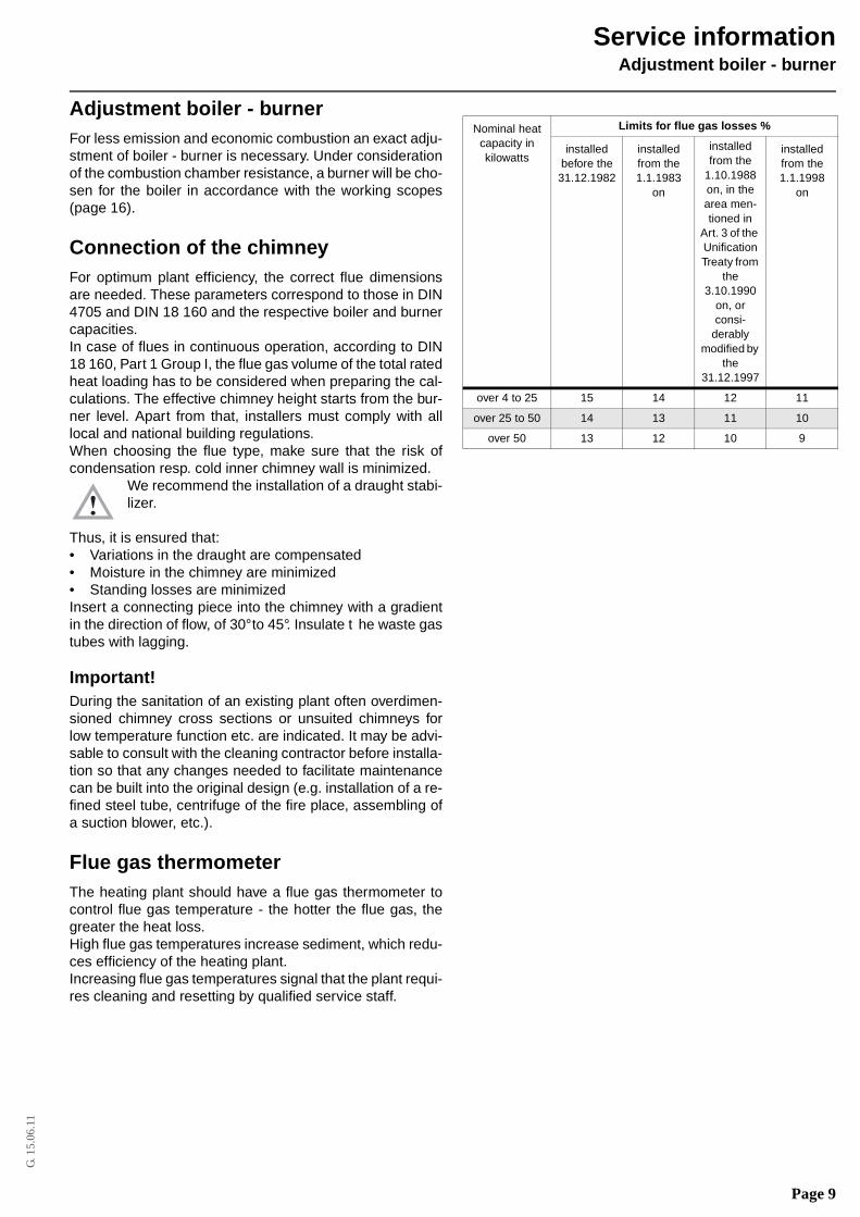
Flue gas thermometerThe heating plant should have a flue gas thermometer tocontrol flue gas temperature - the hotter the flue gas, thegreater the heat loss.High flue gas temperatures increase sediment, which redu-ces efficiency of the heating plant.Increasing flue gas temperatures signal that the plant requi-res cleaning and resetting by qualified service staff.
Nominal heat capacity in kilowatts
Limits for flue gas losses %
installed before the31.12.1982
installedfrom the1.1.1983
on
installedfrom the
1.10.1988 on, in the area men-tioned in
Art. 3 of the Unification Treaty from
the 3.10.1990
on, or consi-
derably modified by
the 31.12.1997
installed from the1.1.1998
on
over 4 to 25 15 14 12 11
over 25 to 50 14 13 11 10
over 50 13 12 10 9
Service information
Page 10
G. 1
5.06
.11
Explosion drawing and parts list R1(- V)(-L)
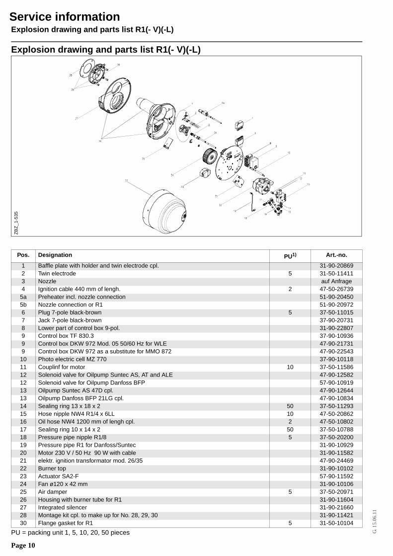
Explosion drawing and parts list R1(- V)(-L)
PU = packing unit 1, 5, 10, 20, 50 pieces
Pos. Designation PU1) Art.-no.
1 Baffle plate with holder and twin electrode cpl. 31-90-208692 Twin electrode 5 31-50-114113 Nozzle auf Anfrage4 Ignition cable 440 mm of lengh. 2 47-50-26739
5a Preheater incl. nozzle connection 51-90-204505b Nozzle connection or R1 51-90-209726 Plug 7-pole black-brown 5 37-50-110157 Jack 7-pole black-brown 37-90-207318 Lower part of control box 9-pol. 31-90-228079 Control box TF 830.3 37-90-109369 Control box DKW 972 Mod. 05 50/60 Hz for WLE 47-90-217319 Control box DKW 972 as a substitute for MMO 872 47-90-22543
10 Photo electric cell MZ 770 37-90-1011811 Couplinf for motor 10 37-50-1158612 Solenoid valve for Oilpump Suntec AS, AT and ALE 47-90-1258212 Solenoid valve for Oilpump Danfoss BFP 57-90-1091913 Oilpump Suntec AS 47D cpl. 47-90-1264413 Oilpump Danfoss BFP 21LG cpl. 47-90-1083414 Sealing ring 13 x 18 x 2 50 37-50-1129315 Hose nipple NW4 R1/4 x 6LL 10 47-50-2086216 Oil hose NW4 1200 mm of lengh cpl. 2 47-50-1080217 Sealing ring 10 x 14 x 2 50 37-50-1078818 Pressure pipe nipple R1/8 5 37-50-2020019 Pressure pipe R1 for Danfoss/Suntec 31-90-1092920 Motor 230 V / 50 Hz 90 W with cable 31-90-1158221 elektr. ignition transformator mod. 26/35 47-90-2446922 Burner top 31-90-1010223 Actuator SA2-F 57-90-1159224 Fan ø120 x 42 mm 31-90-1010625 Air damper 5 37-50-2097126 Housing with burner tube for R1 31-90-1160427 Integrated silencer 31-90-2166028 Montage kit cpl. to make up for No. 28, 29, 30 31-90-1142130 Flange gasket for R1 5 31-50-10104
ZB
Z_1
-535
Service information
Page 11
G. 1
5.06
.11
Wiring diagrams
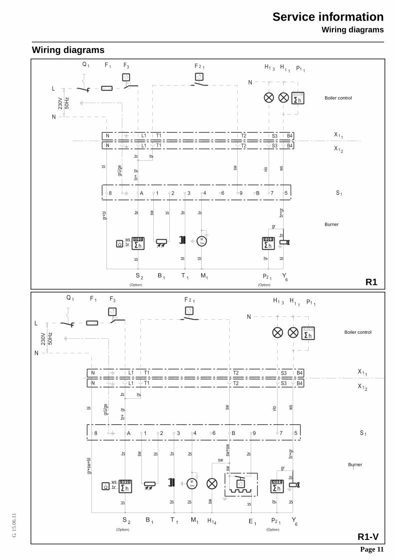
Wiring diagrams
Service information
h
4
sw
Kesselregelung
Q
S 2br
Brenner
1X1
1X2
1S
vio ws
gr
br+g
rblgr
br
blblbl
gr+b
lbl
br gr
br+
gr
~
(Option) (Option)
23
0V
50
Hz
grü/
ge
sw br brbl
wsbr
1 F 1
h
L1N T1 T2 S3
B4L1 S3T2T1N
B4
h
P1 1H
1
N
F 12 HQ
M
1
8 1 2 3 96 B 7 5A
LN
3F
B 1 T 1 M1 P2 1Y
6
31
1
R1
Boiler control
Burner
R1-V
h
sw+s
w
Kesselregelung
Q
S 2
br
Brenner
1X1
1X2
1S
vio ws
gr
br+g
rblgr
br
blbr
sw
sw
swblblbl
gr+s
w+b
lbl
br gr
br+
gr sw
~
(Option) (Option)
230V
50H
z
grü/
ge
sw br brbl
wsbr
1 F 1
h
L1N T1 T2 S3
B4L1 S3T2T1N
B4
h
P1 1H
1
N
F 12 HQ
M
1
8 1 2 3 4 B6 9 7 5A
LN
3F
B 1 T 1 M1 E 1P2 1
Y6
31
1
1H 4
Boiler control
Burner
Page 12
G. 1
5.06
.11
Wiring diagrams
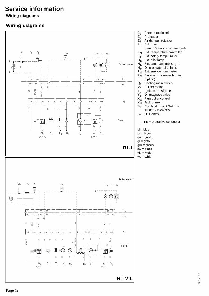
Wiring diagrams
Service information
R1-L
Boiler control
Burner
R1-V-L
h
sw+s
w
Kesselregelung
Q
S 2
br
Brenner
1X1
1X2
1S
vio ws
gr
br+g
rblgr
br
blbl
brbr
sw
sw
sw
swblblbl
gr+s
w+b
lbl
br gr
br+
gr sw
~
(Option) (Option)
230V
50H
z
grü/
ge
sw br brbl
wsbr
1 F 1
h
L1N T1 T2 S3
B4L1 S3T2T1N
B4
h
P1 1H
1
N
F 12 HQ
M
1
8
M
1 2 3 4 B6 9 7 5A
LN
3F
B 1 T 1 M1 E 1 E 2P2 1
Y6
31
1
1H 4
Stromlaufplan R1-V-L
Burner
Boiler control
B1 Photo-electric cellE1 PreheaterE2 Air damper actuatorF1 Ext. fuse
(max. 10 amp recommended)F21 Ext. temperature controllerF3 Ext. safety temp. limiterH11 Ext. pilot lampH13 Ext. lamp fault messageH14 Oil preheater pilot lampP11 Ext. service hour meterP21 Service hour meter burner
(option)Q1 Heating main switchM1 Burner motorT1 Ignition transformerY6 Oil magnetic valveX11 Plug boiler controlX12 Jack burnerS1 Combustion unit Satronic
TF 830 / DKW 972S2 Oil Control
PE = protective conductor
bl = bluebr = brownge = yellowgr = greygrü = greensw = blackvio = violetws = whitr
Page 13
G. 1
5.06
.11
Fault diagnosis
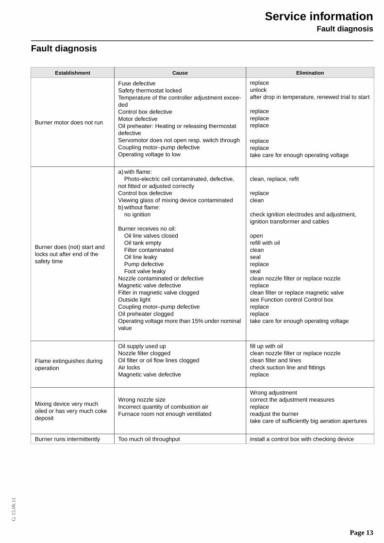
Fault diagnosis
Establishment Cause Elimination
Burner motor does not run
Fuse defectiveSafety thermostat lockedTemperature of the controller adjustment excee-dedControl box defectiveMotor defectiveOil preheater: Heating or releasing thermostat defectiveServomotor does not open resp. switch throughCoupling motor–pump defectiveOperating voltage to low
replaceunlockafter drop in temperature, renewed trial to start
replacereplacereplace
replacereplacetake care for enough operating voltage
Burner does (not) start and locks out after end of the safety time
a) with flame:Photo-electric cell contaminated, defective,
not fitted or adjusted correctlyControl box defectiveViewing glass of mixing device contaminatedb) without flame:
no ignition
Burner receives no oil:Oil line valves closedOil tank emptyFilter contaminatedOil line leakyPump defectiveFoot valve leaky
Nozzle contaminated or defectiveMagnetic valve defectiveFilter in magnetic valve cloggedOutside lightCoupling motor–pump defectiveOil preheater cloggedOperating voltage more than 15% under nominal value
clean, replace, refit
replaceclean
check ignition electrodes and adjustment,ignition transformer and cables
openrefill with oilcleansealreplacesealclean nozzle filter or replace nozzlereplaceclean filter or replace magnetic valvesee Function control Control boxreplacereplacetake care for enough operating voltage
Flame extinguishes during operation
Oil supply used upNozzle filter cloggedOil filter or oil flow lines cloggedAir locksMagnetic valve defective
fill up with oilclean nozzle filter or replace nozzleclean filter and linescheck suction line and fittingsreplace
Mixing device very much oiled or has very much coke deposit
Wrong nozzle sizeIncorrect quantity of combustion airFurnace room not enough ventilated
Wrong adjustmentcorrect the adjustment measuresreplacereadjust the burnertake care of sufficiently big aeration apertures
Burner runs intermittently Too much oil throughput install a control box with checking device
Service information
Page 14
G. 1
5.06
.11
Adjustment table
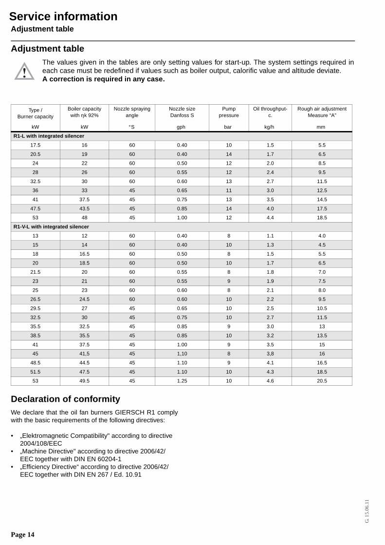
Adjustment tableThe values given in the tables are only setting values for start-up. The system settings required ineach case must be redefined if values such as boiler output, calorific value and altitude deviate.A correction is required in any case.
Declaration of conformityWe declare that the oil fan burners GIERSCH R1 complywith the basic requirements of the following directives:
• „Elektromagnetic Compatibility" according to directive 2004/108/EEC
• „Machine Directive" according to directive 2006/42/EEC together with DIN EN 60204-1
• „Efficiency Directive“ according to directive 2006/42/EEC together with DIN EN 267 / Ed. 10.91
Type /Burner capacity
Boiler capacity with ηk 92%
Nozzle spraying angle
Nozzle sizeDanfoss S
Pump pressure
Oil throughput-c.
Rough air adjustmentMeasure “A”
kW kW ° S gph bar kg/h mm
R1-L with integrated silencer
17.5 16 60 0.40 10 1.5 5.5
20.5 19 60 0.40 14 1.7 6.5
24 22 60 0.50 12 2.0 8.5
28 26 60 0.55 12 2.4 9.5
32.5 30 60 0.60 13 2.7 11.5
36 33 45 0.65 11 3.0 12.5
41 37.5 45 0.75 13 3.5 14.5
47.5 43.5 45 0.85 14 4.0 17.5
53 48 45 1.00 12 4.4 18.5
R1-V-L with integrated silencer
13 12 60 0.40 8 1.1 4.0
15 14 60 0.40 10 1.3 4.5
18 16.5 60 0.50 8 1.5 5.5
20 18.5 60 0.50 10 1.7 6.5
21.5 20 60 0.55 8 1.8 7.0
23 21 60 0.55 9 1.9 7.5
25 23 60 0.60 8 2.1 8.0
26.5 24.5 60 0.60 10 2.2 9.5
29.5 27 45 0.65 10 2.5 10.5
32.5 30 45 0.75 10 2.7 11.5
35.5 32.5 45 0.85 9 3.0 13
38.5 35.5 45 0.85 10 3.2 13.5
41 37.5 45 1.00 9 3.5 15
45 41,5 45 1,10 8 3,8 16
48.5 44.5 45 1.10 9 4.1 16.5
51.5 47.5 45 1.10 10 4.3 18.5
53 49.5 45 1.25 10 4.6 20.5
Service information

Page 15
G. 1
5.06
.11
Declaration of conformity
G. 1
5.06
.11
• 06
-201
1 •
Art
. Nr.
70-1
1-57
000-
GB
• P
rinte
d in
Ger
man
y •
Ene
rtec
h G
mbH
Enertech GmbH • Brenner und HeizsystemeAdjutantenkamp 18 • D-58675 Hemer • Telefon 02372/965-0 • Telefax 02372/61240E-Mail: [email protected] • Internet: http://www.giersch.de
All information in this technical documentation as well as the drawings, pho-tos and technical descriptions placed at your disposal remain our propertyand may not be duplicated without our written permission given in advance.Subject to alterations.
GIERSCH
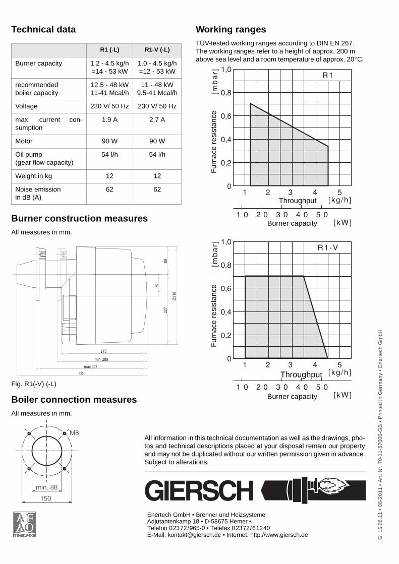
Technical data
Burner construction measuresAll measures in mm.
Fig. R1(-V) (-L)
Boiler connection measuresAll measures in mm.
Working rangesTÜV-tested working ranges according to DIN EN 267.The working ranges refer to a height of approx. 200 mabove sea level and a room temperature of approx. 20° C.
R1 (-L) R1-V (-L)
Burner capacity 1.2 - 4.5 kg/h=14 - 53 kW
1.0 - 4.5 kg/h=12 - 53 kW
recommended boiler capacity
12.5 - 48 kW11-41 Mcal/h
11 - 48 kW9.5-41 Mcal/h
Voltage 230 V/ 50 Hz 230 V/ 50 Hz
max. current con-sumption
1.9 A 2.7 A
Motor 90 W 90 W
Oil pump(gear flow capacity)
54 l/h 54 l/h
Weight in kg 12 12
Noise emission in dB (A)
62 62
420
70
Ø31
6
8922
7
275
max 357
min 288
M8
min. 88
150
Durchsatz [kg/h]
R1
Brenner le is tung [kW]F
eu
err
au
mw
ide
rsta
nd
[m
ba
r]
1 2 3 4 5
1 0 2 0 3 0 4 0 5 0
1,0
0,8
0,6
0,4
0,2
0
Throughput
Burner capacityF
urna
ce r
esis
tanc
e
R1-V1,0
0,8
0,6
0,4
0,2
0
Durchsatz [kg/h]
Brenner le is tung [kW]
Fe
ue
rra
um
wid
ers
tan
d [
mb
ar]
1 2 3 4 5
1 0 2 0 3 0 4 0 5 0
Fur
nace
res
ista
nce
Throughput
Burner capacity


![Gas burnersite-262930.mozfiles.com/files/262930/PR_Gasbrenner-Z... · 2015-09-01 · Series RG. Burner output [kW] Furnace resistance [mbar] Gas pipe connection with the use of sound](https://static.fdocuments.us/doc/165x107/5f4ecfe47b20fa697242b0bc/gas-burnersite-2015-09-01-series-rg-burner-output-kw-furnace-resistance-mbar.jpg)

