
Technical Handbook - honeywellanalytics.com/media/honeywell-analytics/... · procedures described...
129
Apex Technical Handbook
Transcript of Technical Handbook - honeywellanalytics.com/media/honeywell-analytics/... · procedures described...

1
MAN0604_Issue 09_02-2013 Apex2110M8030
Apex
Technical Handbook

2
MAN0604_Issue 09_02-2013 Apex2110M8030
SAFETYEnsure that you read and understand this handbook BEFORE installing/operating the equipment. Pay particular attention to the Safety Warnings.
WARningS1. Thisgasdetectionequipmentiscertifiedforandintendedforuseinpotentiallyhazardous
areas. Install and use the equipment in accordance with current local and national regulations.
2. Refertothecontroldrawingsincludedinthisdocumentwheninstallingthecertifiedcomponents.
3. Operators should be fully aware of the action to be taken if the gas concentration exceeds alarm level.
4. Donotmodifyoraltertheconstructionofanyoftheunitsasessentialsafetyandcertificationrequirements may be invalidated.
5. The equipment is not suitable for use in oxygen enriched atmospheres (>21%V/V). Oxygen deficientatmospheres(<10%V/V)maysuppresssomesensoroutputs.
6. The equipment is intended for use at atmospheric pressure only and should not be used in pressures exceeding 1.1 bar.
Transmitter Unit only1. inpUT vOlTAgE mUST nOT ExcEEd ThE STATEd mAximUm (32v dc) AS
ESSEnTiAl SAFETY REqUiREmEnTS mAY BE invAlidATEd And ThE UniT mAY BE pERmAnEnTlY dAmAgEd.
2. Alarmsshouldnotberesetuntilitisconfirmedthatgasisnot present.
3. Hazardousvoltagesmayexistatalarmcontacts.Ensurepowerisdisconnectedatsourceprior to servicing contacts.
4. Gas events occurring while accessing the Transmitter Unit menus will not be reported locally.
5. Overrangeflammablegasreadingsmayindicateanexplosiveconcentrationofgas.
Certified Sensor only1. WheninstalledtomeasureflammablegasitisessentialthateithertheTransmitterunitor
controlnetworkisconfiguredtolatchtheoverrangecondition.IftheTransmitterunitlocalrelays are used this should be achieved by enabling the overrange latching function of the Transmitterunit.Depletionofoxygenasaconsequenceofdisplacementbyflammablegascanresultinthegasreadingreturningtozero.
2. Change gas cartridges using the procedure described in this handbook. Failure to correctly follow the procedure could result in the wrong cartridge being installed, and possibly non-detection of events. Alternatively, extraneous alarms could be triggered by chemicals detected but not of concern at a particular location.
3. Sensor cartridges may contain corrosive solutions. Dispose of in accordance with local and national regulations.
4. Duringusage,assomegasesmaybehazardous,outletsfromaccessories,etc.,e.g.FlowHousing, should exhaust to a safe area.

3
MAN0604_Issue 09_02-2013 Apex2110M8030
SAFETYcAUTiOnS
1. Only the combustible gas detection portion of this instrument has been assessed for performance by CSA.
2. Refer to local or national regulations relative to installation and use at the site. Note: This equipment is designed and constructed to prevent ignition sources arising,
even in the event of frequent disturbances or equipment operating faults. The electrical input is protected with a fuse.
3. Installation should consider not only optimum siting for gas detection related to potential leak points, gas characteristics and ventilation but also placement where the potential for mechanical damage is minimised or avoided.
4. Observe precautions for handling electrostatic discharge sensitive devices when accessing the interior of the Transmitter Unit.
5. Calibrationproceduresshouldonlybeperformedbyqualifiedpersonnel.6. Ensure that when forcing signals on the Transmitter Unit’s output that the effects on the
network and controller are understood.7. EnsurethattheApexTransmitterUnitorJunctionBoxflamepathisnotdamagedduring
dismantlingprocedures.Theflamepathisformedbythematingsurfacesoftheunit’stop and base.
8. During installation/maintenance only use the supplied parts. Replacement with alternatives willinvalidatecertification.
9. Exposuretofluorinatedhydrocarbonsorsiliconeswillpoisonthesensorbeadsoncatalyticsensor cartridges. If a sensor is known to have been poisoned then it must be re-calibrated. Ifnotsurethenflowgasoverthesensorandifthereadingisincorrectre-calibratewithinthecartridge’s tolerance value.
10.OnlycartridgeswiththefollowingpartnumberscanbefittedtotheCertifiedSensor: 2110B30x0,31x0,32x0,33x0,34x0,35x0series 2110B3700-2110B3999range
Note: CertifiedtoCSA C22.2 No. 152onlywhenfittedwithspecificcartridges. Seespecificationsfordetails.
11.Donotusetheunitwherethetemperatureislowerthan-40°C(-40°F)orhigherthan +65°C(149°F).
12. Exposures to gas above the recommended range may result in ambiguous readings and may require subsequent re-calibration of the sensor.
13. Review cartridge data sheets for operating temperatures and humidities, which are determined on a cartridge by cartridge basis.
14.Disposeofinaccordancewithlocaldisposalregulations.Materialsused: Transmitter Unit
MainBody: StainlessSteel UserInterface: ZincAlloy
Certified Sensor MainBody: StainlessSteel
Certified Junction Box Mainbody: Stainlesssteel
4
MAN0604_Issue 09_02-2013 Apex2110M8030
cOnTEnTSSAFETY 2
1. inTROdUcTiOn 8
2. OvERviEW 102.1 Transmitter Unit 102.2 Certified Sensor 122.3 Accessories 14
2.3.1 CertifiedJunctionBox 142.3.2 Collecting Cone 162.3.3 Flow Housing 172.3.4 Weather Housing 182.3.5 Sunshade 182.3.6 Oxygen Transducer Adaptor 192.3.7 Filters 19
3. inSTAllATiOn 20General Installation Guidelines 21
3.1 Transmitter Unit and Certified Sensor 223.1.1 Installing the Transmitter Unit 223.1.2 FittingtheCertifiedSensor 253.1.3 Installing the Gas Sensing Cartridge 273.1.4 TransmitterUnitConfiguration 29
3.2 Certified Junction Box and Certified Sensor 313.2.1 InstallingtheCertifiedJunctionBox 323.2.2 FittingtheCertifiedSensor 343.2.3 Installing the Gas Sensing Cartridge 363.2.4 CertifiedJunctionBoxConfiguration 37
3.3 LonWorks Communications Board 383.3.1 Removing the Transmitter Unit top 393.3.2 RemovingtheMainPCBassemblyfromthetop 403.3.3 Fitting the LonWorks Communication Board to
theMainPCB 403.3.4 RefittingtheMainPCBAssemblyintotheTop 413.3.5 Connecting the LonWorks Network Wiring 423.3.6 RefittingtheTransmitterUnitTop 43
3.4 Accessories 463.4.1 Flow Housing, Weather Protection, Collecting Cone 463.4.2 Sunshade 47
4. OPERATION 494.1 Display and Control Buttons 49
4.1.1 LCDscreen 504.1.2 Controlbuttons 50

5
MAN0604_Issue 09_02-2013 Apex2110M8030
cOnTEnTS4.2 Start-up 514.3 Passwords 52
4.3.1 Setting/changing passwords 534.3.2 Password reset 55
4.4 Menus 564.4.1 Calibration Menu 574.4.2 ConfigurationMenu 634.4.3 Display Menu 714.4.4 History Log Menu 744.4.5 Change Passwords Menu 754.4.6 Reset Passwords 76
4.5 User Tasks 774.6 Fault Diagnosis 78
4.6.1 Displayed Error Messages 784.6.2 General Faults 794.6.3 4-20mAoutputsignalrangesandfaultconditions 804.6.4 Clearing latched alarms 81
4.7 System Calibration 824.8 Binding Communication Boards to Networks 87
5. MAINTENANCE 895.1 Routine maintenance schedule 895.2 Maintenance Procedures /Parts Replacement 90
5.2.1 ChangingtheCertifiedSensorFilter 905.2.2 ChangingtheCertifiedSensorCartridge 915.2.3 ChangingtheCertifiedSensor 955.2.4 Changing the Transmitter Unit Front Panel Assembly 98
APPENDIX A - SPECIFICATIONS 100A.1 Transmitter Unit and Sensor 100
A.1.1 GasesandRanges 100A.1.2 Input/Output 100A.1.3 Monitoringfunctions 102A.1.4 Performance 102A.1.5 Environmental 102A.1.6 Storage(excludingcartridge) 102A.1.7 EMC 103A.1.8 Enclosure 103A.1.9 Configuration 103A.1.10 CertificationandApprovals 103A.1.11 Calibrationintervals 105
A.2 Cartridges 105A.2.1 Cartridgetables 105

6
MAN0604_Issue 09_02-2013 Apex2110M8030
cOnTEnTSA.3 Accessories 111
A.3.1 CertifiedJunctionBox 111A.3.2 Sunshade 112A.3.3 Flow Housing 113A.3.4 Weather Protection 113A.3.5 Collecting Cone 113A.3.6 Oxygen Transducer Adaptor 113
A.4 LonWorks Communications Board 113A.4.1 LonWorks Network Variables 114A.4.2 Node Object 114A.4.3 Sensor Object 116A.4.4 Virtual Function Block 117A.4.5 Implementation of nviRequest 118A.4.6 Interpretation of nvoStatus 119
APPENDIX B - CERTIFICATION 120B.1 Transmitter Unit 120B.2 Certified Sensor 121B.3 Certified Junction Box 123B.4 Accessories 124B.5 Control Drawings 125
APPENDIX C - ACCESSORIES & SPARE PARTS 127C.1 Accessories 127C.2 Digital Communications Board 127C.3 Spares 127
APPENDIX D - GLOSSARY 128

7
MAN0604_Issue 09_02-2013 Apex2110M8030

8
MAN0604_Issue 09_02-2013 Apex2110M8030
1. inTROdUcTiOnApexisagasdetectionsystemthatconsistsofaTransmitterUnit,acertifiedgassensorandasetofaccessories.TheTransmitterUnit,CertifiedSensorandCertifiedJunctionBoxaccessoryareallcertifiedforuseinpotentiallyhazardousareasandareprotectedagainstwateranddustingress to IP67.
Typical working environments are oil and gas distribution, petroleum extraction and chemical manufacture.
System installation is straightforward. Components should be installed in accordance with the procedures described in this handbook and to local or national installation codes of practice.
The Transmitter Unit acts as the local system controller and features a large LCD screen and four control buttons that are used for operator interaction. Control of the system is implemented via a system of software-driven hierarchical menus that include such operations as cartridge change, systemconfiguration,etc.Remotecontrolofthesystemcanbemadeviaanoptional digital interface.
TheTransmitterUnitcanhavetheCertifiedSensorfittedtoitlocallyormountedremotelyusingaCertifiedJunctionBoxandadditionalcablingupto100metreslong.
TheTransmitterUnitprovidesa4-20mAoutput,aswellasanoptionaldigitaloutput.Relaysforoperating locally-wired devices, such as lights, horns, etc. are included. The range of accessories enhances operation of the system and includes a collecting cone, weather protection, etc.
TheCertifiedSensoriscompatiblewitharangeofmorethan40sensorcartridgesthatusecatalyticbead,thickfilmandelectrochemicalcells.
The interchangeable sensor cartridge determines which gas is monitored. All gas cartridges are fully calibrated when supplied.
TheCertifiedSensorusesintrinsicallysafecircuitstodrivethecartridges.Cartridgesmaythereforebe exchanged without powering down even in the presence of an explosive gas atmosphere.
Field calibration of the sensor, if required, is also possible. The cartridges available are listed in Appendix A.
The output from the sensor provides a gas concentration reading that is displayed on the LCD screenonthefrontoftheTransmitterUnitandisalsotransmittedonthe4-20mAoutputandtheoptional digital interface.

9
MAN0604_Issue 09_02-2013 Apex2110M8030
1. inTROdUcTiOnThishandbookconsistsofthefollowingparts:
• Chapter 1 Introduction • Chapter 2 Overview • Chapter 3 Installation • Chapter 4 Operation • Chapter 5 Maintenance • Appendix A Specifications • Appendix B Certification • Appendix C Accessories & Spare Parts • Appendix D Glossary
Information notices
Thetypesofinformationnoticesusedthroughoutthishandbookareasfollows:
WARningIndicateshazardousorunsafepracticewhichcouldresult
in severe injury or death to personnel.
Caution: Indicates hazardous or unsafe practice which could result in minor injury to personnel, or product or property damage.
Note: Provides useful/helpful/additional information.
TrademarksThefollowingtrademarksareusedinthishandbook:
Teflon® and Freon® are registered trademarks of E.I. DuPont de Nemours and Co.
LonWorks®, Echelon®, Neuron®, and LonTalk® are registered trademarks of Echelon Corporation.
If more information outside the scope of this technical handbook is required please contact Honeywell Analytics.

10
MAN0604_Issue 09_02-2013 Apex2110M8030
This chapter provides an overview of the following system components, and provides their dimensions:
• Transmitter Unit • Certified Sensor • AccessoriesFor installation information see Chapter 3.
Also see drawing 2110C8049 Outline Dimensions of Certified Transmitter, Sensor & Accessories (available on request from Honeywell Analytics).
2.1 TRAnSmiTTER UniT TheTransmitterUnitprovidesamountingpointforaCertifiedSensorandcontainsalltheelectronicsassociated with the gas detection system.
It features an LCD display screen that displays the controlling software menu system, and also a set of buttons that let an operator/user interact with the system by accessing the menus and responding to displayed messages.
TheTransmitterUnitisshownwithaCertifiedSensorfitted.
2. OvERviEW
LCD screen
Certification label
Top retainingcable
Buttons
Ribbon cable Unit top
LCD screen assemblysecuring screw
(2 off)

11
MAN0604_Issue 09_02-2013 Apex2110M8030
Cable/conduit entry sealing plug (1 off)
Interconnect PCB
Locating pins
Externalearth
Unit base
CertifiedSensor mounting
Cable / conduitentry (2 off)
Captive bolt(3 off)
2. OvERviEW

12
MAN0604_Issue 09_02-2013 Apex2110M8030
2.2 cERTiFiEd SEnSORTheCertifiedSensorconsistsofthesensorbodyandoneoffourtypesofreplaceablegascartridgeandtheelectronicstooutputgassensingdatatotheApexTransmitterUnit.TheCertifiedSensorcanbefittedwithanyoneofanumberofaccessories,themajorityofwhichfitinplaceofthesensorcap (see 2.3).
Thefourtypesofcartridgeare:
• electrochemical cell • catalytic (SG16 type) • oxygen • thick filmCaution: Onlycartridgeswiththefollowingpartnumberscanbefittedtothe
CertifiedSensor: 2110B30x0, 31x0, 32x0, 33x0, 34x0, 35x0 series 2110B3700 - 2110B3999 rangeCertifiedSensorapprovedtoCSA C22.2 No. 152onlywhenfittedwithspecificcartridgesinstalled.Seespecificationsfordetails.
The sensor should be mounted in the vertical orientation with the cartridge facing downwards.
2. OvERviEW

13
MAN0604_Issue 09_02-2013 Apex2110M8030
2. OvERviEW
AllthegascartridgesarethesamesizeexceptfortheOxygencartridge,whichislargerthantherest. To allow for its extra length an Oxygen Transducer Adaptor, supplied with the cartridge, mounts onthesensorbayonetfixing.TheOxygencartridgeistheninsertedandthecaporaccessoryfitted.
Cartridge
Cap or accessory
Seal orfilteroptional
Sensor body
Sensor cable
Certification label
L WL GE REEZ
53mm
165mm(177mm with
Oxygentransducer)
Oxygen transduceradaptor

14
MAN0604_Issue 09_02-2013 Apex2110M8030
2.3 AccESSORiESTheApexaccessoriesprovideoptionalequipmentthatcan,forexample,protecttheCertified Sensor in harsh external environments and assist gas monitoring. All of the sensor accessories are easilyfitted.
Thefollowingaccessoriesareavailable:
• Certified Junction Box (Part Numbers: ATEX Ex d 2110B2100, UL/CSA [Explosion proof] 2110B2103) - two typesforremotemountingaCertifiedSensor.
• Collecting Cone(PartNo:2110B2151)-forusewhen monitoring lighter-than-air gases.
• Flow Housing(PartNo:2110B2140)-toaidsensor calibration and gas sample monitoring.
• Weather Housing (PartNo:2110B2150)-toprotectthe sensor from harsh weather.
• Sunshade (PartNo:2110B2152) - to protect the sensor from direct sunlight.
• Filters -threedifferentfilterstoprovideprotectionforthe gas sensing cartridge.
• O2 Transducer Adaptor - supplied with Oxygen cartridges to allow for their longer length over standard cartridges.
2.3.1 Certified Junction BoxPart Numbers: ATEX Ex d 2110B2100 UL/CSA (Explosion proof) 2110B2103TheCertifiedJunctionBoxaccessoryisusedtomountaCertifiedSensorremotelyfromtheTransmitterUnit,andprovidesaconnectionpointforthesensorandfieldwiring.
2. OvERviEW
Certification label
Lid retaining cable Certified Junction
Box Top
Flamepath

15
MAN0604_Issue 09_02-2013 Apex2110M8030
2. OvERviEW
InterconnectPCB
Externalearth
Unit base Certified
Sensor mountingCable / conduit
entry (2 off)
Captive bolt(3 off)
152mm
95
mm

16
MAN0604_Issue 09_02-2013 Apex2110M8030
2. OvERviEW2.3.2 Collecting Cone Caution: This accessory should not be used for calibration purposes.Part Number: 2110B2151
160mm
12
7m
m
The Collecting Cone is only for use when monitoring lighter-than-air gases.
Itsshapeisdesignedto:
• increasethecollectionareaforlighterthanairgases • allowthegasestoescapesothatthetimetoclearanalarmisnot
excessively prolonged. • fitagainstawallorotherflatsurface
Conforms to CSA C22.2 No. 152whenfittedtotheCertifiedSensorwithspecificcartridgesinstalled.Seespecificationsfordetails.
TheCollectingConeisattachedtothesensorbymeansofabayonetfitting.
Insidetheconeisa1/4in.O/Dnozzlethatcanacceptatubeandwhichprovidesameanstodirectlyinjectgastothefrontofthesensorforgasresponsechecking.Therecommendedflowrateforresponse checks is 1 litre per minute.
Accuracy of reading is not guaranteed.
Note: Do not carry out response checks at wind speeds greater than 10m/s (22mph).

17
MAN0604_Issue 09_02-2013 Apex2110M8030
2. OvERviEW2.3.3 Flow Housing Part Number: 2110B2140
The Flow Housing accessory provides a means of applying gas to the sensor for calibration and test (for details see section 4.7). It can also be used in sampling systems where a sample of gas is drawn through a tube to the sensor. Conforms to CSA C22.2 No. 152whenfittedtotheCertifiedSensorwithspecificcartridgesinstalled.Seespecificationsfordetails.
Itprovides:
• Twoports8mmI/Dtotake6mmtubing.
• Asealtostopgasdilution.
Thehousingworksirrespectiveofwhichpipethegasisappliedtoandflowsgasacrossthefaceofthe sensor rather than onto its face.
The difference in reading between a calibration made with the Flow Housing accessory and one madeunderdiffusionconditions(inatankofstillgas)islessthan30%.TheFlowHousingissuitableforflowratesintherangeof0.7-1litreperminuteflowacrossthecell.
Ahydrophobicfilterissuppliedwiththehousingwhichmust beusedwhencalibratingsensorsfittedwithflammablegascartridges.
Whencalibratingsensorsfittedwithothertypesofcartridgethenthefiltermountedinthesensorcapfornormalgassensingoperation(iffitted)mustberemovedandusedintheFlowHousing.
TheFlowHousingaccessoryisattachedtothesensorbymeansofabayonetfitting.
53mm
43mm

18
MAN0604_Issue 09_02-2013 Apex2110M8030
2.3.4 Weather HousingCaution: This accessory should not be used for calibration purposes. This accessory is not recommended for use in still air conditions.Part Number: 2110B2150
2. OvERviEW
The Weather Housing accessory protects the sensor from hosing down/ cleaning operations and from extreme weather conditions, (e.g. torrential rain, storms, gales etc.). Conforms to cSA c22.2 No. 152whenfittedtotheCertifiedSensorwithspecificcartridgesinstalled.Seespecifications for details.
Theweatherhousingshouldnotbefittediftheoperatingenvironmentofthesensordoesnotrequirethe additional protection afforded. In still air conditions the gas is transported to the face of the sinter is by diffusion only. Under such conditions the weather protection will slow the rate at which gas can reach the sensing element and consequently the speed of response of the sensor to gas will be reduced.
As well as providing weather protection the housing also provides a means to directly inject gas to thefrontofthesensorviaa1/4in.O/Dnozzleforgasresponsechecking.Therecommendedflowrate for response checks is 1 litre per minute. Accuracy of reading is not guaranteed. Do not carry outresponsechecksatwindspeedsgreaterthan10m/s(22mph).
Theaccessoryisattachedtothesensorbymeansofabayonetfitting.
Note: The sensor will exhibit an increased reading(or indication) to gas with higher wind speeds. Fittingtheweatherhousingwiththesuppliedhydrophobicfilterwilleliminatethiseffectbut increase the response time.
53mm
57mm

19
MAN0604_Issue 09_02-2013 Apex2110M8030
2. OvERviEW2.3.5 Sunshade Part Number: 2110B2152
115mm
145m
mThe Sunshade prevents excessive heating of the sensor by direct sunlight. Conforms to cSA c22.2 No. 152whenfittedtotheCertifiedSensorwithspecificcartridgesinstalled.Seespecifications for details.
Thesunshadeisfittedtothesensorbodybymeansofaclamp.
2.3.6 Oxygen Transducer Adaptor
The Oxygen Transducer Adaptor is supplied with the Oxygen cartridge and is necessary because the depth of the Oxygen cartridge is more than that of the other gas cartridges.
TheadaptorisattachedtotheCertifiedSensorbymeansofabayonetfitting.TheOxygencartridgeisfittedfirstandthesensorcaporaccessoryisthenfittedtotheadaptorbymeansofabayonetfitting.
2.3.7 FiltersOneofthreedifferenttypesoffilteraccessorycanbefittedtotheCertifiedSensorinplaceoftherubberseal inside the sensor cap or accessory.
Thethreedifferenttypesoffilteravailableare:
Mesh filter - Part Number: 2110B2170 - for use in harsh environments.Thefilterpreventsdirtfromblockingthe cartridge sinter.
Hydrophobic filter - Part Number: 2110B2171 - for use in environments where the cartridge front is likely to become wet. The hydrophobic material allows gas to pass through but notwater.AhydrophobicfilterissuppliedwiththeFlow Housing and must beusedwhencalibratingsensorsfitted withflammablegascartridges.
Caution: Thesensitivityofsomecartridgesmaybedegradedbythehydrophobicfilter.
Carbon filter - Part Number: 2110B2172-foruseinenvironmentswheresignificant volatilecompoundsarepresent.Thefilterpreventsthecartridgefrombeingcritically affected.
53mm
18m
m

20
MAN0604_Issue 09_02-2013 Apex2110M8030
3. inSTAllATiOnThe Apex system components can be used together in a variety of ways for different installation requirementsinahazardousenvironment.ForinstallationsofcertifiedcomponentsalsorefertotheControl Drawings in Appendix B.
The following types of system installation are typical examplesofthosethatcanbemade:
• Apex Transmitter unit with a Certified Sensor locally mounted at the Transmitter Unit and field wiring from the Transmitter Unit to the system controller.
• Transmitter unit with a Certified Sensor mounted remotely in a Certified Junction Box, with field wiring between the two components, and from the Transmitter Unit to the system controller.
Thischapterdescribeshowto:
• carry out the installation of a Transmitter Unit and Certified Sensor • install an Certified Junction Box accessory with Certified Sensor, suitable for
remote operation • install a LonWorks Communications Board in a Transmitter Unit
This is to enable the unit to be controlled and communicate over a digital network, e.g. LonWorks.
Caution: DonotinstallacommunicationsboardintoaULorCSAcertifiedTransmitterUnit • install the system accessoriesWhenfittingthesystemcomponentsconsiderationshouldbemaderegardingpotentialgasleaksources, density of the gas to be detected, probability of mechanical impacts and interference from other equipment and apparatus.
ForoptimumperformancetheTransmitterUnitandCertifiedSensorshouldbeinstalledinalocationfree from dust and direct sunlight. Sunshade and weather protection accessories for the sensor are available when operating in harsh external environments (see 3.4).
Refertotherelevantcontrolsystemmanualforexternalnetworkconnectioninformation(e.g.fieldwiring, etc.).

21
MAN0604_Issue 09_02-2013 Apex2110M8030
Also see drawing 2110C8049 Outline Dimensions of Certified Transmitter, Sensor & Accessories (available on request from Honeywell Analytics).
General Installation GuidelinesThe following general points should be noted before any installation is carried out.
• Read all the instructions before starting any of the installation procedures. • Identify a suitable location with a flat surface where the Apex Transmitter Unit/
Certified Junction Box can be mounted. • Identify external cable requirements and the necessary cable/conduit entry
ports to be used on the Apex Transmitter Unit/Certified Junction Box. • The Certified Sensor must always point downwards to avoid collection of fluids
and other materials on the face. • When fitting components that are certified also refer to the Control Drawings
(see Appendix B).ThesystemcomponentscomplywiththeEMCrequirementsofEN50270.Inordertomaintaincompliance with this standard it is essential that the components are installed correctly as detailed below. It is the responsibility of the installation design authority to ensure that the electrical installation meets appropriate standards.
1. The unit should not be electrically connected to electrically noisy (dirty) metalwork or conductors. The case should be connected to a low noise (clean) earth line via the screen on thefieldcabling.
2. Theentirelengthofthefieldcablingconnectedtoeachunitshouldbefullyscreenedwiththescreen connected to a low noise earth.
3. The low noise earth line should only be connected to safety earth at a single point. Star earthing arrangements minimise earth current crosstalk. Field cabling shields should not be connected such that earth loops are produced.
4. The earth bonding arrangement must ensure that the maximum peak voltage between the unitcaseearthandanyfieldcableconductorislessthan350V.Voltagesinexcessofthiscancausepermanentdamagetotheunit'sRFIprotectionfilters.
5. The use of a single, screening cable for each gas detector ensures maximum screening and minimum crosstalk. Cabling arrangements which use a single cable for connecting fielddevicescompromisescreening,increasethepotentialforcrosstalkandpreventimplementation of true star earthing.
3. inSTAllATiOn

22
MAN0604_Issue 09_02-2013 Apex2110M8030
6. Anyelectricalinterferenceinducedontothe4-20mAloopconductorsbytheinstallationmustbekeptbelowthelevelsnecessarytocomplywiththegeneralrequirementsofEN50270.In practice, this means that peak noise currents induced on the current loop should be no greaterthan±0.25mA.
7. The0Vrailofthecontrolcard/systemisoftendirectlyconnectedtoonesideofthe4-20mAcurrent sensing resistor. Electrical noise on such a rail is therefore directly connected to the 4-20mAinput.Inordertoavoidadditionalnoisebeinginducedonthe0Vrail,itshouldnotbecommon with the safety earth/ground which frequently carries a high level of electrical noise.
8. The24Vsupplyshouldbefreefromlargetransientsandfluctuations.
ThetypeofcableusedforfieldwiringbetweentheApextransmitterandcontrolequipment,andbetween the Apex transmitter and Apex sensor if mounted remotely, should be selected to meet the environmentalandhazardousarearequirements.Thecableinternalconstructionshouldbeaofthescreened, multi-core, multi-stranded type. The terminals within the product will accept a maximum conductorsizeof2.5mm2(14AWG).Therecommendedminimumconductorsizeis0.75mm2 (20AWG).Theconductorsshouldbesizedtogiveatotalpowersupplyloopresistanceoflessthan30Ohms(ECCcartridge)or160hms(Catalyticcartridge). If remote mounting the sensor from the transmitter a 4-core, screened cable with a minimum conductorsizeof0.75mm2(20AWG)isrequired.
3.1 TRAnSmiTTER UniT And cERTiFiEd SEnSORThisinstallationconsistsofaTransmitterUnitwithCertifiedSensorlocallymountedattheTransmitterUnittogetherwithfieldwiring.
To/fromcontroller
Apex Transmitter Unitwith Certified Sensor
Apex Transmitter Unitwith Certified Sensor(North America-style
installation)
Apex Transmitter Unitwith Certified Sensor
(European-styleinstallation)
The system components can be installed by a single technician.
Thisproceduredescribeshowto:
• install a Transmitter Unit • fit a Certified Sensor to the local Transmitter Unit • connect up the Certified Sensor and field wiring • configure the Transmitter Unit relay and alarm settings • install a gas sensing cartridge into the Certified SensorRefer to the General Installation Guidelines at the beginning of this chapter.
3. inSTAllATiOn
Apex Transmitter Unitwith Certified Sensor mounted
in Certified Junction Box(European-style installation)
Certified Junction Boxwith Certified Sensor
Apex Transmitter Unit
o

23
MAN0604_Issue 09_02-2013 Apex2110M8030
3.1.1 Installing the Transmitter UnitCautions:1. Observe precautions for handling electrostatic discharge sensitive devices.2. EnsurethattheApexTransmitterUnitflamepathisnotdamagedduringthisprocedure.
TheflamepathisformedbythematingsurfacesoftheApexTransmitterUnittopandbase (see diagram).
(1) Isolate all associated power supplies and ensure that they remain OFF during the installation procedure. Ensure a gas free atmosphere.
(2) Attach the Apex Transmitter Unit to the supporting structure.Drill two mounting holes (68mm apart) and use the unit’s mounting slots in the base with either two M10 bolts or a single 10mm U-bolt Cable/conduit entry sealing plug
Top retainingcable
Unit top
ZIF
Locatingpins
Externalearth
Unit base
CertifiedSensor mounting
pointCable/conduitentry (2 off)
Captive bolt(3 off)
Interconnect PCBRibbon cable
Flamepath
Flame-path
Cable securing screw
(3) Detach the top of the Transmitter Unit.Unscrew the three captive M8 bolts in the base. Support the top and let the metal retaining cable, attaching the top to the base, hold the top. Take care not to damage or strain the ribbon cable between the top and the base.
(4) Fitandconnectthefieldwiring.
See the subsequent wiring table and diagram. Use either: Conduit - using one or both of the 3/4 NPT conduit entries. Ensure that a conduit sealing
fittingisinstalledwithin460mmoftheenclosureonallconduitruns.
3. inSTAllATiOn

24
MAN0604_Issue 09_02-2013 Apex2110M8030
Cable-usinganysuitableflameproofcableentrydevicecertifiedaEquipmenttoDirective94/9/EC(ATEX).
Note: Allunusedcable/conduitentriesmustbesealedwithasuitablecertifiedsealingplug(oneplug is supplied).
Typical wiring arrangements to the Transmitter Unit are (with all cables screened):
Single cable/conduit entry
Power 4-20mA Digital Comms Relays Cores used
2 1 - - 3
2 2 - - 4
2 2 - 6 10
2 2 2 - 6
2 - 2 - 4
Twin cable/conduit entries
Power 4-20mA Digital Comms Relays
2 2 (4 cores) - 6 (6 cores) 2 2 2 (6 cores) 6 (6 cores) 2 x power in 2 x power out
--
2 x comms in (4 cores) 2 x comms out (4 cores)
--
MorecomplexwiringschemesmayneedtouseexternalCertifiedJunctionBoxeseitherbecause of cable/conduit entry capacity or because there are more than two cable/conduit destinations.
3. inSTAllATiOn

25
MAN0604_Issue 09_02-2013 Apex2110M8030
3. inSTAllATiOn3.1.2 Fitting the Certified Sensor(1) FittheCertifiedSensortotheTransmitterUnit.
FeedthesensorcablethroughtheCertifiedSensormountingpointatthefrontoftheTransmitterUnitbase.Screwthesensorfirmlyintothemountingpointuntilitisfullyhome.
(2) Connect the sensor wiring. See the following wiring table and diagram.
Terminal Function Colour Recommended Number Wire Length
SK3 1 CAN_L White 40mm(Sensor) 2 CAN_H Green 40mm 3 +V Red 40mm 4 0V Black 40mm 5 Screen 40mm
SK4 1 NET1 60mm(Comms 2 NET2 60mmand
3 Ground 50mmPower) 4 4-20mA- 50mm
5 4-20mA+ 50mm 6 0V 50mm 7 +24Vdc(18-32Vdc) 50mm
SK6 1 Fault 50mm(Relays) 2 Faultcommon 50mm 3 Alarm1 50mm 4 Alarm1common 50mm 5 Alarm2 50mm 6 Alarm2common 50mm g - Earth Green/Yellow
Certified Sensormounting point
Certified Sensor
Transmitter Unitbase

26
MAN0604_Issue 09_02-2013 Apex2110M8030
3. inSTAllATiOn
Ground
Ground
SK3
SK4SK6
(3) ConfiguretheTransmitterUnitifrequired.
SetthelinksontheInterconnectPCBfortherequiredrelaycontactsettingsandforthe 4-20mA topology. See 3.1.4.
(4) Refitthetoptothebase.
Cautions: 1. Ensurethatthereisnomoistureinsidetheunitbeforefittingthetop.2. Use only the captive bolts supplied, replacement with alternative bolts will invalidate
certification. Follow the reverse of the removal procedure supporting the top. The top should be positioned
using the locating pins on the Apex Transmitter Unit base and then lowered onto the base.
Ensure that the lid retaining cable and wiring is not trapped and the O-ring in the top is correctly located. Ensure that the ribbon cable is not twisted and is correctly positioned. Check that there is no discernible gap between the top and the base. Tighten the three captive M8 bolts to 5Nm (3.68 foot-pounds).

27
MAN0604_Issue 09_02-2013 Apex2110M8030
3. inSTAllATiOn3.1.3 Installing the Gas Sensing Cartridge
(1) RemovethecapfromtheCertifiedSensorbody.Rotate the cap or accessory 1/4 turn in an anticlockwise direction to release the bayonet fitting.
(2) Fit the gas sensing cartridge into the sensor body.
Sensor body
Cartridge fitted to sensorbody
Sensor cap
WARning
Sensor Cartridges may contain corrosive solutions. Dispose of according to local and national regulations.
Eachcartridgeisprovidedwithacertificateofcalibration(printedonthereverseoftheinstruction sheet, Part No: 2110M8015, supplied with the cartridge) that guarantees that the cartridgeiscalibratedandreadyforuse.Beforeinstallingacartridgecheckthatthenumberon the cartridge label matches the gas type and range for the function required.
Caution: OnlycartridgeswiththefollowingpartnumberscanbefittedtotheCertifiedSensor:
2110B30x0, 31x0, 32x0, 33x0, 34x0, 35x0 series 2110B3700 - 2110B3999 rangeNote: Conforms to CSA C22.2 No. 152onlywhenfittedwithspecificcartridges.Seespecifications
for details.
CarefullyplugthecartridgeintotheCertifiedSensorbodyensuringthatthecartridgetab lines up with the recess in the sensor body and push the cartridge, without twisting, until it is fully home.
If the cartridge will not push fully home, re-check that the locating tab is correctly aligned with the recess in the sensor body. Position the tab so it is resting on the tab recess wall to the right or left of the tab recess and then turn the cartridge until the tab drops into the recess.

28
MAN0604_Issue 09_02-2013 Apex2110M8030
3. inSTAllATiOnCaution: Do not force the cartridge as this may cause damage to the pins of the connecting
plugs. Twisting and pushing can bend the pins and make the cartridge inoperative.
Socket (2 off)
Locatingtab
recess
Sensor body
Plug(2 off)
Locatingtab
Cartridge
Note: IffittinganOxygencartridgeensurethattheOxygenTransducerAdaptorsuppliedwiththeOxygencartridgeisfittedtotheCertifiedSensorbody.Theadaptorisfittedtothesensorbodyviaabayonetfitting.
(3) RefitthecaptotheCertifiedSensor.
Reverse the removal procedure.
(4) Check for correct operation of the system by carrying out the procedures described in Chapter 4.
Sensor body
Cartridge fitted to sensorbody
Sensor cap

29
MAN0604_Issue 09_02-2013 Apex2110M8030
3. inSTAllATiOn3.1.4 Transmitter Unit ConfigurationCaution: Do not change either Relay or 4-20mA link setting while unit is powered up.
Thefollowinginformationspecifiestheunitconfigurationoptions.
RelaysLinks J1, J2 and J3 set the contact operation for the Fault, Alarm 1 and Alarm 2 relays respectively.
J1 (Fault relay - normally energised)
Normally open (default) Normally closed
J2 and J3 (Alarm 1 and 2 Relays - normally de-energised) Normally open (default) Normally closed
Note: Relay states shown are the shelf state. Relay contacts are rated at 100mA (min), 2A (max), 30Vdc non-inductive*. HIGHER VOLTAGES MUST NOT BE USED (*ULspecification:28Vdc,1A)
J1 J2 J3
J4
J5
J1 J2 J3
Fault Alarm Alarm1 2

30
MAN0604_Issue 09_02-2013 Apex2110M8030
4-20mA loopThesummarytableandsubsequentdiagramsidentifythelinkandterminalsettingsfor4-20mA loop options.
link SK4 4 - 20mA loop topology Terminal Isolated Source Sink
J4 -
J5 - - 4 4-20mA- 4-20mA- notused
- 5 4-20mA+ notused 4-20mA+
Note: Total 4-20mA loop resistance should be less than 300 ohms. Total power supply loop resistance should be less than 30 ohms (ECC cartridge) or 16 ohms (catalytic cartridge). Typical power consumption with relays active is 3.6W (ECC cartridge) or 5.6W (catalytic cartridge).
Isolated Mode (4-wire)
3. inSTAllATiOn
J5
SK4J4
4 - 20mA -
4 - 20mA +
1
2
3
4567
0V
+24V dc

31
MAN0604_Issue 09_02-2013 Apex2110M8030
3. inSTAllATiOnCurrent Sink Mode (3-wire)
Current Source Mode (3-wire)
J5
SK4J4
4 - 20mA +
123
567
0V+24V dc
4
J5
SK4J4
4 - 20mA -
1234
67
0V+24V dc
5

32
MAN0604_Issue 09_02-2013 Apex2110M8030
3. inSTAllATiOn3.2 CERTIFIED JUNCTION BOX And cERTiFiEd SEnSORThisinstallationconsistsofaCertifiedJunctionBoxaccessorywiththeCertifiedSensorlocallymountedattheboxtogetherwithfieldwiring.
Apex Transmitter Unitwith Certified Sensor mounted
in Certified Junction Box(North America-style installation)
Certified Junction Boxwith Certified Sensor
Apex Transmitter Unit
o
Apex Transmitter Unitwith Certified Sensor mounted
in Certified Junction Box(European-style installation)
Certified Junction Boxwith Certified Sensor
Apex Transmitter Unit
o
The system components can be installed by a single technician. Thisproceduredescribeshowto:
• install a Certified Junction Box • fit the Certified Sensor to the Certified Junction Box • connect up the Certified Sensor and field wiring • configure the Certified Junction Box • install a gas sensing cartridge into the Certified SensorRefer to the General Installation Guidelines at the beginning of this chapter

33
MAN0604_Issue 09_02-2013 Apex2110M8030
3. inSTAllATiOn3.2.1 Installing the Certified Junction Box Caution: EnsurethattheCertifiedJunctionBoxflamepathisnotdamagedduringthis
procedure.TheflamepathisformedbythematingsurfacesoftheCertifiedJunctionBoxtopandbase(seediagrams).
(1) Isolate all associated power supplies and ensure that they remain OFF during the installation procedure. Ensure a gas free atmosphere.
(2) AttachtheCertifiedJunctionBoxtothesupportingstructure.
Drill two mounting holes (68mm apart) and use the unit’s mounting slots in the base with either two M10 bolts or a single 10mm U-bolt.
(3) RemovetheCertifiedJunctionBoxlid.
Unscrew the three captive M8 bolts. The lid is retained by a metal retaining cable attached to the base.
Certification label
Lid retaining cable Certified Junction
Box Top
Flamepath
InterconnectPCB
Externalearth
Sensor mounting point
Cable / conduitentry (2 off)
Captive bolt(3 off)
Terminal block(3 off)
Cable entrysealing
plug (1 off)
Flamepath

34
MAN0604_Issue 09_02-2013 Apex2110M8030
3. inSTAllATiOn(4) Fitandconnectthefieldwiring.
See the subsequent tables and diagram for wiring details. Use either:
Conduit - using one or both of the ¾NPTconduitentries.Ensurethataconduitsealingfittingis installed within 18" of the enclosure on all conduit runs.
Cable-usinganysuitableflameproofcableentrydevicecertifiedasEquipmenttoDirective
94/9/EC(ATEX).
Notes:
1. Allunusedcable/conduitentriesmustbesealedwithacertifiedsealingplug(oneplugissuppliedfitted).
2. For a multi-sensor system using a network loop, both cable/conduit entries are used, one bringingtheloopconnectionsinandtheothertakingthemoutofthebox.Removethefittedcertifiedsealingplugfromthesparecable/conduitentry.
3.2.2 Fitting the Certified Sensor(1) FittheCertifiedSensortotheCertifiedJunctionBox.
Certified Sensormounting point
Certified Sensor
Certified JunctionBox base
Pass the sensor connecting cable through the sensor mounting point and then screw the sensorfirmlyintothesensormountingpointuntilitisfullyhome.
(2) Connect the sensor wiring.
See the following diagram and table for wiring details.

35
MAN0604_Issue 09_02-2013 Apex2110M8030
3. inSTAllATiOn
Terminal/Number Function Colour
SK1 1 CAN_L White SK2 2 CAN_H Green or Blue SK3 3 +V Red
4 0V Black
5 Not used -
SK4 1 Screen * -
2 Screen * -
g - Earth Green/Yellow
* Only connect cable screens to these terminals if they are isolated at the remote end.
Note: Three sensor wiring terminal blocks are provided (SK1, SK2 SK3), any two can be used.
12345
54321
21
1 2 3 4 5
Internal earth
SK4
SK3
SK2 SK1
J1
(3) ConfiguretheCertifiedJunctionBoxifrequired.

36
MAN0604_Issue 09_02-2013 Apex2110M8030
3. inSTAllATiOnSetthelinkontheInterconnectPCBfortherequiredControllerAreanetwork(CAN)setting.See 3.2.4.
(4) RefitthetoptotheCertifiedJunctionBoxbase.
Cautions: 1. EnsurethatthereisnomoistureinsidetheCertifiedJunctionBoxbeforefittingthelid.2. Use only the captive bolts supplied, replacement with alternative bolts will invalidate
certification. ThetopshouldbelocatedusingthelocatingpinsontheCertifiedJunctionBoxbaseandthen
lowered onto the base. Ensure that the lid retaining cable and/or wiring are not trapped and the O-ring in the top is correctly located. Check that there is no discernible gap between the top and the base. Tighten the captive M8 bolts to 5Nm (3.68 foot-pounds).
3.2.3 Installing the Gas Sensing Cartridge
(1) RemovethecapfromtheCertifiedSensorbody.
Sensorbody
Sensorcap
Rotate the cap or accessory 1/4 turn in an anticlockwise direction to release the bayonetfitting.
(2) Fit the gas sensing cartridge into the sensor body.
WARning
Sensor Cartridges may contain corrosive solutions. Dispose of according to local and national regulations.
Eachcartridgeisprovidedwithacertificateofcalibration(printedonthereverseoftheinstruction sheet, Part No: 2110M8015, supplied with the cartridge) that guarantees that the cartridgeiscalibratedandreadyforuse.Beforeinstallingacartridgecheckthatthenumberon the cartridge label matches the gas type and range for the function required.
37
MAN0604_Issue 09_02-2013 Apex2110M8030
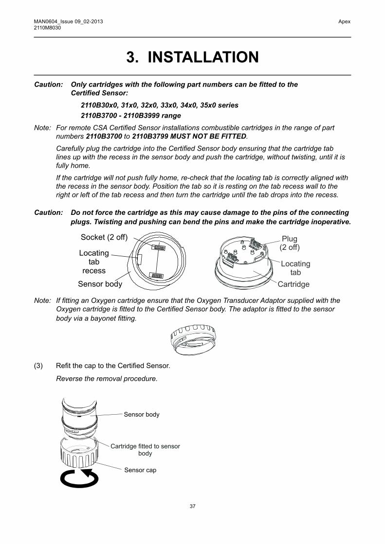
Caution: Onlycartridgeswiththefollowingpartnumberscanbefittedtothe CertifiedSensor:
2110B30x0, 31x0, 32x0, 33x0, 34x0, 35x0 series 2110B3700 - 2110B3999 rangeNote: ForremoteCSACertifiedSensorinstallationscombustiblecartridgesintherangeofpart
numbers 2110B3700 to 2110B3799 MUST NOT BE FITTED.
CarefullyplugthecartridgeintotheCertifiedSensorbodyensuringthatthecartridgetab lines up with the recess in the sensor body and push the cartridge, without twisting, until it is fully home.
If the cartridge will not push fully home, re-check that the locating tab is correctly aligned with the recess in the sensor body. Position the tab so it is resting on the tab recess wall to the right or left of the tab recess and then turn the cartridge until the tab drops into the recess.
Caution: Do not force the cartridge as this may cause damage to the pins of the connecting plugs. Twisting and pushing can bend the pins and make the cartridge inoperative.
Socket (2 off)
Locatingtab
recess
Sensor body
Plug(2 off)
Locatingtab
Cartridge
Note: IffittinganOxygencartridgeensurethattheOxygenTransducerAdaptorsuppliedwiththeOxygencartridgeisfittedtotheCertifiedSensorbody.Theadaptorisfittedtothesensorbodyviaabayonetfitting.
53mm
18m
m
(3) RefitthecaptotheCertifiedSensor.
Reverse the removal procedure.
3. inSTAllATiOn
Sensor body
Cartridge fitted to sensorbody
Sensor cap

38
MAN0604_Issue 09_02-2013 Apex2110M8030
3. inSTAllATiOn(5) Check for correct operation of the system by carrying out the procedures described in
Chapter 4.
3.2.4 Certified Junction Box ConfigurationThefollowinginformationspecifiestheCertifiedJunctionBoxconfigurationoptions.
Controller Area Network (CAN )Termination Link - J1
Terminated Unterminated (default)
Note: Leave the link in the Unterminated position.
3.3 lOnWORKS cOmmUnicATiOnS BOARdThe LonWorks Communications Board can be installed in the Transmitter Unit by a single person. ItisfittedintothetopoftheunittoformpartoftheMainPCBassembly.
Note: DonotinstallacommunicationsboardintoaULorCSAcertifiedTransmitterUnit.
Refer to the General Installation Guidelines at the beginning of this chapter.
Fittingtheboardshouldbecarriedoutbyaqualifiedtechnician.
Electrical interconnections for the communications board are made at the same time as mechanical installation by means of plugs attached to the communications board. These plugs mate with existing socketsonthemainPCBfittedtotheApexTransmitterUnitlid.
OncetheboardisfittedanyexternalLonWorksnetworkwiringrequiredisconnected.
Plug(2 off)
Mounting pillar (4 off)
LonWorks board
Earth lead

39
MAN0604_Issue 09_02-2013 Apex2110M8030
Note: Theboardissuppliedwiththemountingpillarsfittedtoit.Thisproceduredescribeshowto: • remove the Transmitter Unit top • remove the Main PCB assembly from the top • fit the LonWorks Communication Board to the Main PCB • refit the Main PCB assembly into the top • connect the LonWorks network wiring • refit the Transmitter Unit top • operational check and binding the LonWorks Communication Board to
the network
Refer to the General Installation Guidelines at the beginning of this chapter.
3.3.1 Removing the Transmitter Unit topCautions:
1. Observe precautions for handling electrostatic discharge sensitive devices.
2. EnsurethattheApexTransmitterUnitflamepathisnotdamagedduringthisprocedure.TheflamepathisformedbythematingsurfacesoftheApexTransmitterUnittopandbase (see diagram).
(1) Isolate all associated power supplies and ensure that they remain OFF during this procedure. Ensure a gas free atmosphere.
(2) DisconnectfromtheTransmitterUnitbasethewireretainingcablefittedbetweenthetopandthe base.
Unscrew and remove the single M6 hexagon screw that secures the cable to the base.
3. inSTAllATiOn
Top retainingcable
Unit top
ZIF
Locatingpins
Externalearth
Unit base
CertifiedSensor mounting
pointCable / conduit
entry (2 off)
Captive bolt(3 off)
InterconnectPCB
Ribbon cable
Flamepath
Flamepath
Cable securingscrew
Cable entry sealing plug

40
MAN0604_Issue 09_02-2013 Apex2110M8030
3. inSTAllATiOn(3) Detach the top of the Transmitter Unit.
Unscrew the three captive M8 bolts underneath the base. Lift the top clear of the locating pins. Take care not to damage or strain the ribbon cable connecting the top and the base.Support the top and ensure that it is supported whilst the next step is carried out.
(4) UnlatchtheribboncableZeroInsertionForce(ZIF)connectorontheInterconnectPCB.Grip the ends of the ZIF and pull it vertically upwards until it is felt to stop and the ribbon cable is loose.
(5) Pull the ribbon cable clear. Remove the top and take to a workshop area.
3.3.2 Removing the Main PCB assembly from the top(1) Placethetopwiththecertificatefacedownonaflatsurface. This provides access to the components inside the top.
Ribboncable
PCBbafflePCBbaffle
PCB bafflesecuring screw
(2 off)
Main PCBPotted assembly
(2) RemovethePCBBafflefromtheTransmitterUnittop.
UnscrewandremovethetwoPCBBafflesecuringscrews.
(3) DisconnecttheflyingleadplugandsocketconnectingtheMainPCBPottedassemblyto the top.
(4) Slide the Main PCB Potted assembly out of the Apex Transmitter Unit top.

41
MAN0604_Issue 09_02-2013 Apex2110M8030
3.3.3 Fitting the LonWorks Communication Board to the Main PCB
Main PCBPotted assembly
Main PCB
Flying lead
(1) PlacetheMainPCBPottedassemblyonaflatsurfacewiththeflyingleadandplugontop.
PushtheflyingleadtoonesidesothatthereisclearaccesstotheMainPCB.
(2) Remove the LonWorks Communication Board from its antistatic bag.
(3) Position the Communication Board over the Main PCB.Ensure the mounting pillars point downwards. Check that the two plugs on the CommunicationBoardarecorrectlyalignedwiththesocketsontheMainPCBandthemounting pillars are aligned with their mounting holes.
(4) Carefully press the Communication Board down evenly onto the Main PCB.
Ensure that the pillars locate in their mounting holes and the electrical plugs are fully home.
3. inSTAllATiOn
Sockets
Main PCB
Ribboncable
Hole for communicationboard mounting pillarFlying lead
Potted assembly

42
MAN0604_Issue 09_02-2013 Apex2110M8030
3. inSTAllATiOn(5) ReconnecttheflyingleadplugandsocketconnectingtheMainPCBtothetop.
3.3.4 Refitting the Main PCB Assembly into the Top(1) RefittheMainPCBPottedassemblywithCommunicationBoardintothetop.
Reversetheremovalprocedure.Theassemblyshouldbefittedsothatthecommunicationsboard is on the same side as the LCD display with the ribbon cable at the top.
(2) RefitthePCBBaffle.
Caution:Whenrefittingthepartsintothetoptakecarenottodamagetheflyinglead plug assembly wires.
EnsurethattheverticalpartofthebafflegoesbetweentheMainPCBandtheflyinglead (see diagram).
PushtheCommunicationBoardearthleadthroughthetopmiddleholeinthebaffle. Securetheearthleadunderoneofthetwobafflesecuringscrews.Tightenthescrewsto
1.0Nm (0.74 foot-pounds).
3.3.5 Connecting the LonWorks Network Wiring(1) FitandconnectthecommunicationnetworkfieldwiringtoSK4 in the base of the
Transmitter Unit. Refer to the table and diagram for wiring details. Use either:
Conduit - using one or both of the 3/4 NPT conduit entries. Ensure that a conduit sealing fittingisinstalledwithin18"oftheenclosureonallconduitruns.
Cable-usinganysuitableflameproofcableentrydevicecertifiedasEquipmenttoDirective
94/9/EC(ATEX).
Note: Allunusedcable/conduitentriesmustbesealedwithasuitablecertifiedsealingplug(oneplug is supplied with the Apex Transmitter Unit).
Main PCBPotted assembly
Main PCB
Flying lead
PCB baffleTop, middlehole

43
MAN0604_Issue 09_02-2013 Apex2110M8030
Terminal number Function Min. length of cable from entry point
SK4 1 NET1 60mm
(Comms 2 NET2 60mm& Power) 3 Ground 60mm
Note: Three terminal blocks are provided, any two can be used.
3. inSTAllATiOn
123
SK4
3.3.6 Refitting the Transmitter Unit Top(1) Support the top.
Ensure that it is supported whilst the next step is carried out.
(2) ReconnecttotheTransmitterUnitbasethewireretainingcablefittedbetweenthetopand the base.
Fit and tighten the single M6 hexagon screw that secures the cable to the base. Tighten the M6 screw to 3Nm (2.21 foot-pounds). Remove the support for the top and let the top down gently until it is supported by the retaining cable.
(3) ReconnecttheribboncableintotheZIFconnectorontheInterconnectPCBinthebaseoftheTransmitter Unit.
Follow the reverse of the removal procedure ensuring that the ribbon is not twisted and is correctly centred relative to the ZIF connector before insertion. Make sure that the ribbon cable contacts face in the same direction as the arrow on the following diagram. Push the latch on the connector down evenly until it is fully engaged.

44
MAN0604_Issue 09_02-2013 Apex2110M8030
3. inSTAllATiOn
(4) RefitthetoptotheTransmitterUnitbase.
Cautions: 1. Ensurethatthereisnomoistureinsidetheunitbeforefittingthetop.2. Use only the captive bolts supplied, replacement with alternative bolts will invalidate
certification.The top should be located using the locating pins on the Apex base and then lowered onto the base. Ensure no wires are trapped and the O-ring in the top is correctly located. Check that there is no discernible gap between the top and the base. Tighten the captive M8 bolts to 5Nm (3.68 foot-pounds).
(5) Check for correct operation of the system by carrying out the procedures described in the following section.
3.3.7 Operational CheckAfter installing the Communication Board and connecting the communication network wiring it is necessarytocheckthattheApexTransmitterUnit,CertifiedSensorandCommunicationBoardareworking correctly together and also bind the equipment, which now acts together as a node, to the communication network.
(1) Power-up the Transmitter Unit.(2) Check that the Transmitter Unit completes its start-up sequence successfully.
The Gas Reading should be displayed. Refer to the Fault Diagnosis sub-section in Chapter 4 if an error message is displayed.
(3) Press the esc button on the front panel.The Main Menu is displayed.
Main MenuCalibration MenuConfiguration MenuDisplay MenuHistory Log MenuChange Passwords MenuReset Passwords

45
MAN0604_Issue 09_02-2013 Apex2110M8030
(4) Select (highlight) the ConfigurationMenu option.Use the up/down keys.
(5) Press the ok button.(6) Enter the current Level 2 password.
The ConfigurationMenu is displayed.Configuration Menu
Configure Digital
Change CartridgeConfigure 4-20mAConfigure RelaysConfigure Alarms
Select LanguageConfigure Backlight
(7) Select (highlight) the ConfigureDigital option. (8) Press the ok button.
Use the up/down keys.The ConfigureDigitalmenu is shown displaying information similar to the following.
Configure DigitalNetwork Type: LonWorksConnection Type: FTT-10Node Id: 00A176094600Node Address: N/ABaud Rate: 78.0kbit/sNode S/W Ver: 1.0Assert Service PIN
For a full explanation of the information see Chapter 4.
(9) Select the Assert Service PIN option.
(10) Presstheok button.
This binds the node to the network.
The display automatically returns to the ConfigurationMenu.
(11) Press the esc button twice
This returns to the Gas Reading display via the Main Menu.
3.4 ACCESSORIESAlltheaccessoriesexceptfortheSunshadeandfilterarefittedtotheCertifiedSensorinthe same way.
TofitafilterseethefilterreplacementinstructionsgiveninChapter 5.
For the dimensions of the accessories see Chapter 2.
3.4.1 Flow Housing, Weather Protection, Collecting ConeTofittheFlowHousing,WeatherProtection,CollectingConeaccessoriescarryoutthefollowingprocedure.
(1) RemovetheCertifiedSensorcap.
3. inSTAllATiOn

46
MAN0604_Issue 09_02-2013 Apex2110M8030
3. inSTAllATiOn
Sensorbody
Sensorcap
Rotatethecapinananticlockwisedirectionby1/4turntoreleasethebayonetfittingand pull off.
(2) Removetherubbersealorfilterfromthesensorcap.
Lug location
Rubber seal
Filter
Therubbersealorfilterisheldinplaceinthecapbyitsthreelugs.Carefullyprisetherubbersealorfilterfreefromtheluglocationpointsinthecaporaccessory.
(3) FortheCollectingConeonlyfittheconeontothesuppliedhousing.
The Collecting Cone is supplied as a kit of two parts that clip together.
(4) Fittherubberseal/filtertotheaccessory.
Ensurethattherubbersealorfilteriscorrectlyinstalledintheaccessorythecorrectwayround with the three lugs closest to the front face of the accessory and correctly engaged in the locators.
(5) FittheaccessoryontotheCertifiedSensorbody.
Reversethecapremovalprocedure.ThediagramshowstheFlowHousingaccessoryfittedtotheCertifiedSensor.

47
MAN0604_Issue 09_02-2013 Apex2110M8030
3.4.2 SunshadeThe sun shade can be used with other accessories in the range such as the Flow Housing, Weather ProtectionandCollectingCone,butshouldbeattachedbeforeanyotheraccessoriesarefitted,orafter their removal.TofittheSunshadeaccessorycarryoutthefollowingprocedure.(1) RemovetheCertifiedSensorcaporaccessory.
Sensorbody
Sensorcap
Thecaporaccessoryisheldbymeansofabayonetfitting.Unscrew1/4turnanticlockwiseand pull off.
(2) Slide the Sunshade clamp over the sensor body.The shade should be positioned so that the whole sensor is shielded.
(3) Fit the supplied self-tapping screw through the Sunshade clamp's left-hand hole (looking from the clamp end of the Sunshade).The self-tapping screw is a K40x16PT Pan Flange PZ Head.
3. inSTAllATiOn
CertifiedSensor
FlowHousing

48
MAN0604_Issue 09_02-2013 Apex2110M8030
3. inSTAllATiOn
Clampright-hand
hole
Clamp left-handhole
Self-tappingscrew
(4) Drive the screw home into the clamp's right-hand hole until the Sunshade's clamp grips the CertifiedSensorbodytightly.
(5) Refitthesensorcaporaccessory.
Reverse the removal procedure.

49
MAN0604_Issue 09_02-2013 Apex2110M8030
4. OPERATIONThe Apex gas measuring system is controlled from the Transmitter Unit via a menu system, displayed on an LCD screen, and a set of control buttons. Thischapterprovidesoperationalinformationaboutthefollowing:
• Display and control buttons • Start-up • Passwords • Menus • User Tasks • Fault diagnosis • System Calibration • Binding the Communications Board to the Network
IfanoptionaldigitalcommunicationsboardisfittedintheTransmitterUnit,e.g.LonWorks,thencontrol can also be achieved from a remote location.
4.1 DISPLAY AND CONTROL BUTTONS
LCD screen
Control buttonsesc
ok

50
MAN0604_Issue 09_02-2013 Apex2110M8030
4. OPERATION4.1.1 LCD screenThe screen provides a graphical user interface that, during normal operation, displays gas reading information. It also displays information about the system to the user, via a password protected hierarchical system of menus, together with system fault and information messages.
Caution: Gas events occurring whilst in menus are not reported locally.
4.1.2 Control buttonsThefourbuttonsonthefrontpanelbelowtheLCDscreenhavethefollowingfunctions:
(esc) is used to exit/cancel the current screen/option and return to the previous screen/option. (up) is used to move upwards through the menu lists and to select (highlight) a required
menu option. It is also used to increment displayed values. (down) is used to move downwards through the menu lists and to select (highlight) a required
menu option. It is also used to decrement displayed values. (ok) is used to execute/acknowledge the chosen item.
The buttons are also used to enter the current password when required to access different menu levels (see 4.3 and 4.4).
Note: If a user response using the buttons is not made to a required menu action, e.g. change/accept a displayed setting value, then the system waits for approximately 10 minutes before the process is aborted and the unit reverts to normal operation with the display showing the normal Gas Reading screen.
If a value had been displayed and not changed within the timeout period the system reverts to the status quo and uses the previously stored setting.

51
MAN0604_Issue 09_02-2013 Apex2110M8030
4.2 START-UPSwitch on the power supply to the Apex Transmitter Unit.
WithacorrectlyinstalledCertifiedSensorthefollowinginformationisshownsequentiallyonthe LCDscreen:
4. OPERATION
CONNECTING
INITIALISING
CO 100 ppm
HONEYWELLANALYTICS
0TheTransmitterUnitinitiallywaitsfortheCertifiedSensortostabilise,duringwhichperiodthe4-20mAoutputisinhibited(2mA).Waitfor15 minutes to ensure sensor stabilisation has occurred before continuing.
If the sensor does not stabilise during the initialisation period (15 minutes), one of the fault (F) or warning (W) alarm messages shown in Section 4.6 is displayed.
WhentheCertifiedSensorstabilises,theLCDscreenshowsthecurrent Gas Reading together with the gas identity, full scale, and the units of measurement.”
Note:IfthecurrentGasReadingexceedsfullscalethedisplayedreadingwillbereplacedwith ’ >>>>’.”
Thisinformationisalsotransmittedonthe4-20mAoutputandoptionallyonthedigitalnetworkifacommunicationsboardisfittedintheTransmitterUnit.
Note: IftheTransmitterUnithasaLonWorksCommunicationsBoardfittedthentheunitwill,atsome stage, need to be bound to the LonWorks network. To do this carry out the LonWorks binding procedure described at the end of this chapter.
4.3 PASSWORDSCaution: Always store passwords in a secure place. Do not let unauthorised users access
to them.The different parts of the high-level menu structure are protected from different levels of user by assigning a set of three different passwords.
Thethreepasswordlevelscorrespondtothefollowingtypesofsystemuser:
• Level 1 System operator • Level 2 System technician • Level 3 System administrator

52
MAN0604_Issue 09_02-2013 Apex2110M8030
4. OPERATIONFor example the Level 1 Password provides a system operator with access to day-to-day system operations,e.g.resettingalarms,checkingthenumberofhourstothenextCertifiedSensorcalibration, etc.
Level 2 PasswordcouldbeassignedtoatechnicianwhoneedstocarryoutmoredifficultoperationssuchascalibratingtheCertifiedSensor.
Level 3 Password is for the system administrator to initially set and subsequently change passwords.
Oncethethreelevelsofpasswordarespecifiedthentheyareassignedtousersbythesystemadministrator depending on their access authority.
Each password consists of a sequence of control button presses.
When prompted during menu use, the user enters the current four-digit password required by pressing the four buttons in the correct sequence. The entered password is represented on the LCD screen using asterisk characters (*).Notes: 1. The last keystroke is not displayed on the screen. If the password is correct then the menu
action previously selected is implemented immediately. If it is not correct the asterisks are cleared and the user must enter the correct password to proceed.
2. Thedefaultpasswordsuppliedwhentheunitisfirstdeliveredisenteredbypressingthe (ok, up, down and down) buttons in sequence. This provides initial access to all
of the menus.
Thepasswordlevelhierarchyallowsthefollowing: • FunctionsavailableatLevel 1 can also be accessed by using the Level 2 or
Level 3 passwords. • FunctionsavailableatLevel 2 can also be accessed by using the Level 3 password.
They cannot be accessed by Level 1. • FunctionsavailableatLevel 3 can only be accessed by using the Level 3 password.
They cannot be accessed by Level 1 or Level 2.
Note: After changing, the three passwords can also be reset to the default value. Resetting all the passwords can only be carried out by the system administrator (see 4.3.2).
4.3.1 Setting/changing passwordsThis combined procedure describes how to initially set passwords and how to subsequently change them.
(1) Power-up the system.
Wait for the Gas Reading display to stabilise.
(2) Press the esc button.
The Main Menu is displayed.
Main MenuCalibration MenuConfiguration MenuDisplay MenuHistory Log MenuChange Passwords MenuReset Passwords

53
MAN0604_Issue 09_02-2013 Apex2110M8030
(3) Navigate to the Change Passwords Menu option.
Use the (up/down) keys.
(4) Press ok.
(5) Enter the current Level 3 password.
Usethebuttonsonthefrontpanel.Ifsettingpasswordsforthefirsttimeafterunitdeliveryorpassword reset, enter the default password by pressing the (ok, up, down and down) buttons in sequence. Passwords are shown using asterisks (*) on the LCD.
The Change Passwords Menu is then displayed.
Change Passwords MenuLevel 1 PasswordLevel 2 PasswordLevel 3 Password
(6) Navigate to the password level option to be changed.
Use the (up/down) keys.
(7) Press ok.
The following screen is displayed:
Level 1 PasswordEnter Old Password
This example shows the Level 1 Password screen. The screens for Levels 2 and 3 are similar.
(8) Enter the current password for the chosen level.
Usethebuttonsonthefrontpanel.Ifsettingthepasswordforthefirsttimeafterunitdeliveryor password reset, enter the default password by pressing the (ok, up, down and down) buttons in sequence. Passwords are shown using asterisks (*) on the LCD.
The following screen is displayed:
4. OPERATION
Level 1 PasswordEnter New Password
54
MAN0604_Issue 09_02-2013 Apex2110M8030
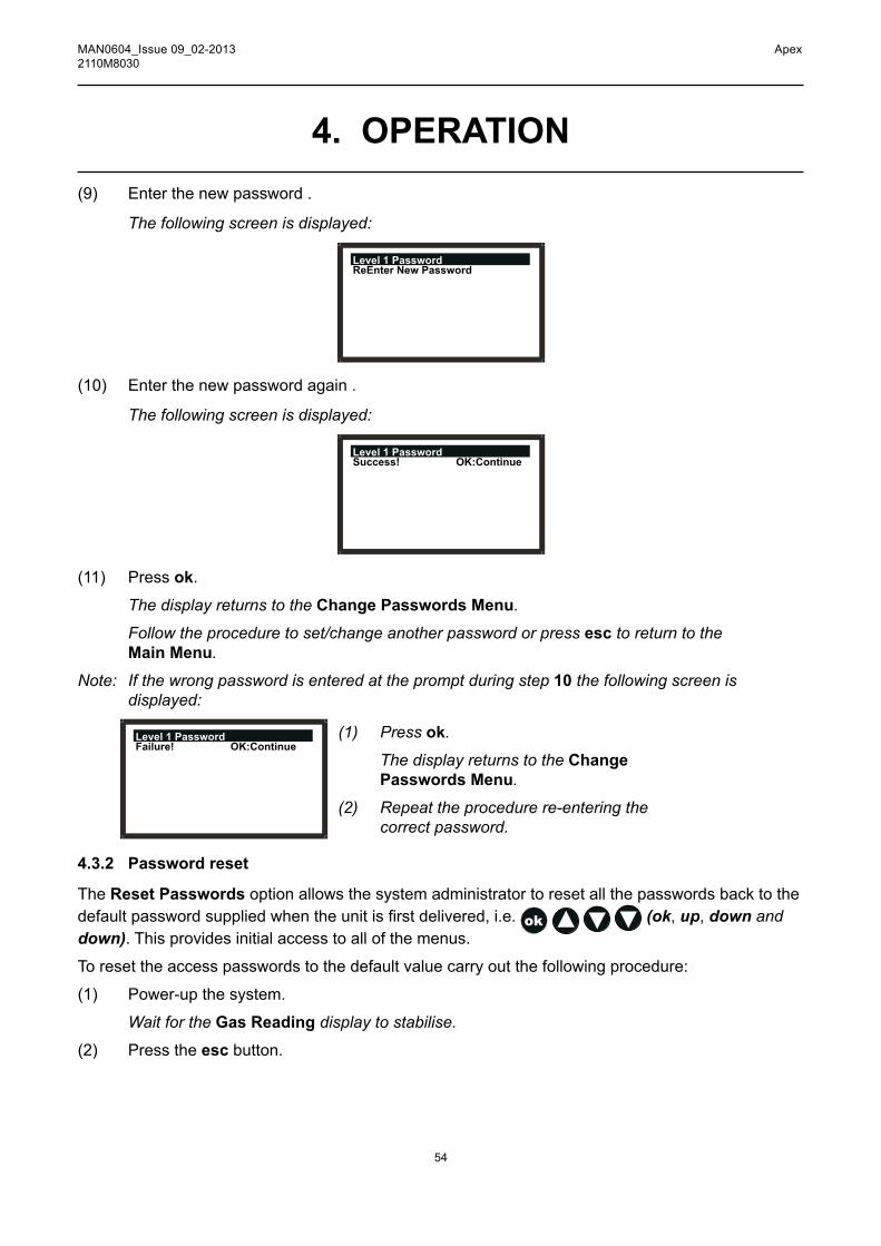
4. OPERATION(9) Enter the new password .
The following screen is displayed:
Level 1 PasswordReEnter New Password
(10) Enterthenewpasswordagain.
The following screen is displayed:
Level 1 PasswordSuccess! OK:Continue
(11) Press ok.
The display returns to the Change Passwords Menu.
Follow the procedure to set/change another password or press esc to return to the Main Menu.
Note: If the wrong password is entered at the prompt during step 10 the following screen is displayed:
Level 1 PasswordFailure! OK:Continue
(1) Press ok.
The display returns to the Change Passwords Menu.
(2) Repeat the procedure re-entering the correct password.
4.3.2 Password reset
The Reset Passwords option allows the system administrator to reset all the passwords back to the defaultpasswordsuppliedwhentheunitisfirstdelivered,i.e. (ok, up, down and down). This provides initial access to all of the menus.
Toresettheaccesspasswordstothedefaultvaluecarryoutthefollowingprocedure:
(1) Power-up the system.
Wait for the Gas Reading display to stabilise.
(2) Press the esc button.

55
MAN0604_Issue 09_02-2013 Apex2110M8030
The Main Menu is displayed.
Main MenuCalibration MenuConfiguration MenuDisplay MenuHistory Log MenuChange Passwords MenuReset Passwords
(3) Navigate to the Reset Passwords option.
Use the up/down keys.
(4) Press ok.
(5) At the prompt enter the following sequence of 8 keystrokes:
(up, down, ok, esc, esc, ok, down, up)
All the passwords are reset to their default value and the display returns to the Main Menu.
4.4 MENUSMenus are used to implement control of the Transmitter Unit.
The system Main Menu is accessed by pressing the esc button at the Gas Reading display.
The Main Menu provides access to the primary tasks that are required when setting-up and controllingtheTransmitterUnitandCertifiedSensor.Thefollowingdiagramsummarisesthemenuhierarchy and options.
4. OPERATION
Main MenuCalibration MenuConfiguration MenuDisplay MenuHistory Log MenuChange Passwords MenuReset Passwords

56
MAN0604_Issue 09_02-2013 Apex2110M8030
4. OPERATION
Main MenuCalibration MenuConfiguration MenuDisplay MenuHistory Log MenuChange Passwords MenuReset Passwords
Calibration MenuGas CalibrateGas Challenge4-20 mA Set ZeroForce 4-20mAForce RelaysForce Digital
Configuration MenuChange CartridgeConfigure 4-20mAConfigure RelaysConfigure AlarmsConfigure DigitalSelect LanguageConfigure Backlight Display Menu
Reset Alarms, FaultsCalibration InfoCurrent Config
History Log Menu View History LogReset History Log
Change Passwords MenuLevel 1 PasswordLevel 2 PasswordLevel 3 Password
The subsequent subsections describe each of the main menu options in turn and show, using a flowchartformat,howtoaccessandimplementtheirsub-options.
Thefollowingsymbolsareusedontheflowchartdiagrams:
Gas Calibrate
Sub-menu option selected.
Zero Calibration screen Sub-menu action.
User action.
Calibrating System process.
Success? Decision.
Use up/down
buttons Comment/instruction.
Button press.
Zero Gas
57
MAN0604_Issue 09_02-2013 Apex2110M8030
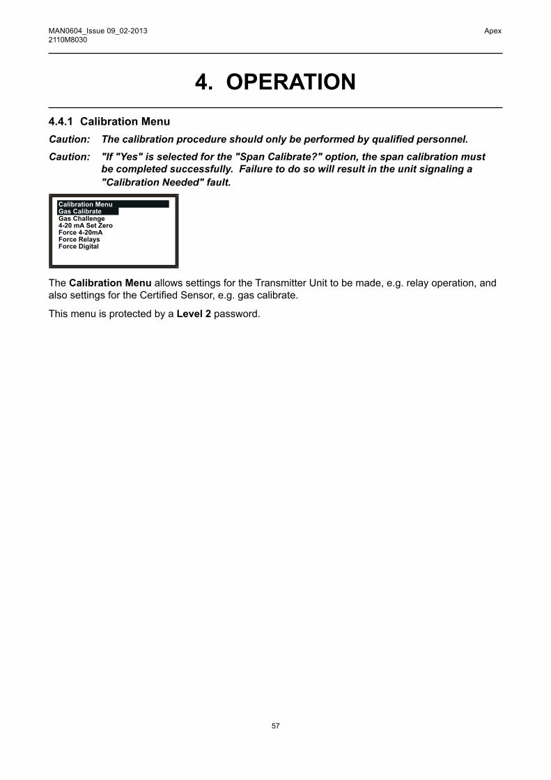
4.4.1 Calibration MenuCaution: Thecalibrationprocedureshouldonlybeperformedbyqualifiedpersonnel.Caution: "If "Yes" is selected for the "Span Calibrate?" option, the span calibration must
be completed successfully. Failure to do so will result in the unit signaling a "Calibration Needed" fault.
Calibration MenuGas CalibrateGas Challenge4-20 mA Set ZeroForce 4-20mAForce RelaysForce Digital
The Calibration Menu allows settings for the Transmitter Unit to be made, e.g. relay operation, and alsosettingsfortheCertifiedSensor,e.g.gascalibrate.
This menu is protected by a Level 2 password.
4. OPERATION

58
MAN0604_Issue 09_02-2013 Apex2110M8030
4. OPERATION
Gas Calibrate Calibration Menu
ThisoptioncalibratestheCertifiedSensorzerogaspointandthespansettingpoint(see4.7 for details of how to carry out this procedure).
Gas Calibrate
ok
Zero Gas
Zero Calibration screen
Calibrating
Success?
Yes
No
Span calibration?
ok
ok
Fault
diagnosis
Yes
NoCalibration
Menu
ok
Span Calibration screen
Set Span
Concentration
(ppm)
ok
Use up/
down
buttons
Apply Gas
ok
Calibrating
Success?
Yes
No
ok
Fault
diagnosis
Calibration Menu
Note: Dependingonthetypeofgascartridgefittedtothesensor,achoiceoftwocalibrationgasesmay be displayed during Span Calibration, e.g. C7H8 has the options C7H8 and CH4 as choices. If so choose the one that will be used for calibration and press ok to continue.

59
MAN0604_Issue 09_02-2013 Apex2110M8030
4. OPERATION
Cautions: 1. Ensure that the area around the sensor is gas free before exiting the Gas Challenge mode.2. Upon leaving gas challenge mode, all outputs return to their active states (from inhibited). Ensure that values have returned to zero to avoid extraneous alarms.Provides the means to check correct operation of the unit in the presence of the gas being sensed without triggering alarms, etc.
SelectingthismenuitemputstheTransmitterUnit’s4-20mAoutputintoInhibitandpreventstherelays from being energised. The Transmitter Unit does not signal Fault if one is induced.
Gas Challenge Calibration Menu
Gas Challenge
ok
Apply Gas
Gas Challenge screen
Gas reading OK?
Yes
No
esc
Fault diagnosis
Calibration Menu

60
MAN0604_Issue 09_02-2013 Apex2110M8030
4. OPERATION
4-20mA Set Zero
ok
4-20mA Set Zero screen
Set zero value -
3.5mA to 4.5mA
ok
Use up/down
buttons
Calibration Menu
4-20mA Set Zero Calibration Menu
This option allows the This option allows thezeropointwithinthe4-20mAsignalrange to be adjusted between 3.5and4.5mA.Thedefaultsettingis4.0mA.Theoffsetappliestoall4-20mAoutputstates including Inhibit, Warning, Overrange and Alarms.
Force 4-20mA Calibration Menu
Caution: Ensure that when forcing a signal on the 4-20mA output that the effects on the network and controller are understood.
Thisoptionallowsthe4-20mAoutputtobeforcedtoalevelselectedbetween0and 22mA. The default is 1mA. The forced setting times out after approximately 5 minutes and the output returns to normal active operation.
Force 4-20mA
ok
Force 4-20mA screen
Set value - 0mA
to 22mA
esc
Use up/down
buttons
Calibration Menu
61
MAN0604_Issue 09_02-2013 Apex2110M8030
4. OPERATION
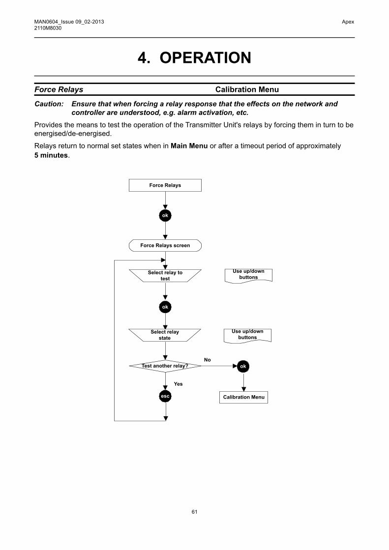
Force Relays Calibration Menu
Caution: Ensure that when forcing a relay response that the effects on the network and controller are understood, e.g. alarm activation, etc.
Provides the means to test the operation of the Transmitter Unit's relays by forcing them in turn to be energised/de-energised.
Relays return to normal set states when in Main Menu or after a timeout period of approximately 5 minutes.
Force Relays
ok
Select relay to
test
Force Relays screen
Test another relay?
Yes
No
ok
esc Calibration Menu
ok
Use up/down
buttons
Select relay
state
Use up/down
buttons

62
MAN0604_Issue 09_02-2013 Apex2110M8030
4. OPERATION
Force Digital Calibration Menu
Caution: Ensure that when forcing a signal on the digital output that the effects on the network and controller are understood, e.g. alarm activation, etc.
Thisoptionallowsthedigitaloutput(ifadigitalcommunicationsboardisfittedtotheTransmitterUnit,e.g. LonWorks) to be forced to output an alarm signal, from Alarm 1 or Alarm 2 or no alarm.
Timesoutafterapproximately5minutes.The4-20mAoutputandrelaysareunaffected.
Force Digital
ok
Force Digital screen
Select output
from 0, 1 or 2
esc
Use up/down
buttons
0 = No output
1 = Alarm 1 output
2 = Alarm 2 output
Calibration Menu

63
MAN0604_Issue 09_02-2013 Apex2110M8030
4. OPERATION4.4.2 Configuration Menu
Configuration MenuChange CartridgeConfigure 4-20mAConfigure RelaysConfigure AlarmsConfigure DigitalSelect LanguageConfigure Backlight
Note: The Configure Backlight optionisnotavailableonCSACertifiedTransmitterUnits.TheConfigurationMenuchangessettingsfortheTransmitterUnit,e.g.alarmoperation,andalsoconfiguresCertifiedSensoroperations,e.g.whenchangingtheCertifiedSensorgascartridge.
This menu is protected by a Level 2 password.
Change Cartridge Configuration Menu
ThismenuitemallowstheCertifiedSensorgascartridgetobechangedundercontrolledconditionswithout generating faults or alarms. The process detects the presence or absence of the cartridge.
If a new cartridge type is inserted, the default alarm thresholds are loaded into the Transmitter Unit.
Note: If the new cartridge has different parameters to the previous cartridge, these are displayed for the operator to verify.
Ifanewcartridgeofthesametypeaspreviouslyusedisinserted,theconfiguredalarmthresholdsofthe Transmitter Unit are loaded into the new cartridge’s actual parameters.
Caution: This only works if the Lowest Allowable Alarm Level (LAL) of the new cartridge is lowerthanthetransmitter’sconfiguredalarmthreshold.Ifitisnot,aFatalFaulterror occurs.
This menu uses procedures from Chapter 5 where details about how to physically change the cartridge are provided.
WARNINGSChange cartridges using the procedure described below.Failure to correctly follow this procedure could result in thewrong cartridge being installed, and possibly non-detectionof events. Alternatively, extraneous alarms could betriggered by chemicals detected but not of concern at aparticular location.
Sensor Cartridges may contain corrosive solutions.Dispose of according to local and national regulations.
!

64
MAN0604_Issue 09_02-2013 Apex2110M8030
4. OPERATION
Configure4-20mA Configuration Menu
Providesthemeanstoconfigurethevaluesforthe4-20mAsignaloutputsettings.Threesettingsareavailable:
Inhibit Value 1mA to 4mA, default is 1mA.
Warning Value 1mA to 6mA, default is 3mA.
Overrange Value20mAto21.5mA,defaultis21mA.
Caution:WhencompliancewiththeATEXperformancestandardisrequiredthewarningandinhibitcurrentshallnotbeconfiguredtoavaluebetweenthan3.1mAand4.9mA
Onceconfiguredtoanewvalue,thenewvalueisoutputwhenthecorrespondingstatesoccur.
WhentheWarningcurrentisconfiguredtobegreaterthan4mAtheoutputpulsestotheconfiguredWarningcurrentforapproximately1secondevery10seconds.
Change Cartridge
ok
Change
cartridge
Change Cartridge screen
Checking
Success?
Yes
No
ok
ok
Fault diagnosis
Calibration Menu
Follow cartridge
change
instructions
See Section 5

65
MAN0604_Issue 09_02-2013 Apex2110M8030
Configure 4-20mA
ok
Select settingto change
Configure 4-20mA screen
Select another setting?
Yes
No
ok
ok Calibration Menu
esc
Use up/down buttons tochoose setting from:InhibitWarningOverrange
Select valueUse up/down
buttons
ok
4. OPERATION

66
MAN0604_Issue 09_02-2013 Apex2110M8030
4. OPERATION
ConfigureRelays Configuration Menu
ThisoptionallowsthethreeTransmitterUnitrelaystobeconfiguredforthecurrentinstallation.
Latched relays are cleared by the Display Menu => Reset Alarms, Faults option or by switching the power off and on.
Configure Relays
ok
Select relay toconfigure
Configure Relays screen
Select another relay?
Yes
No
ok
ok ConfigurationMenu
esc
Use up/down buttons tochoose setting from:Fault RelayAlarm1 RelayAlarm2 Relay
Select relaystate
ok
Use up/down buttons to choose state from:ND (Normally De-energised) Non-LatchingNE (Normally Energised) Non-LatchingND LatchingNE Latching
Note: Alarm recovery is below alarm setpoint (25%).As well as the ability to set the default state of the relay operation (energised or de-energised and latching or non-latching) by this method it is possible to set whether the relay contacts are normally open or normally closed by means of the links on the Transmitter Unit's Interconnect PCB (also see Chapter 3).

67
MAN0604_Issue 09_02-2013 Apex2110M8030
4. OPERATIONFault relay configuration exampleRequirement: Normally De-energised, Non-Latching with the contact Normally Closed.
Implementation: Use the Configure Relays menu option to set the Fault relay operation requirement. Place the jumper on the J1 linktosetthecontactoperationasfollows:
This circuit diagram shows this.
NormallyClosed
NormallyOpen
Fault Common
Fault
J1
Fault
Alarm 1
Alarm 2
SK6
6
5
4
3
2
1
FaultRelay
(Relay inde-energised
state)
Other relayssimilar
J2 J3
J1

68
MAN0604_Issue 09_02-2013 Apex2110M8030
4. OPERATION
ConfigureAlarms Configuration Menu
Caution: Alarm 2 value can be set below Alarm 1 value.
When installed to measure flammable gas it is essential thateither the Transmitter unit or control network is configured tolatch the overrange condition. If the Transmitter unit localrelays are used this should be achieved by enabling theoverrange latching function of the Transmitter unit. Depletionof oxygen as a consequence of displacement by flammablegas can result in the gas reading returning to zero.
Providesthemeanstoconfigurethepointatwhichthealarmsactivateandwhetheroverrangelatchingisrequired.Therangeofsettingsdependsonthetypeofgascartridgefittedtothe CertifiedSensor.When the Transmitter Unit’s alarm thresholds are changed, the actual cartridge parameters are updatedtoreflecttheTransmitterUnit'sconfiguredvalues.The default state for Overrange latching is not latched.When activated, overrange latching causes the Transmitter Unit to latch the A1 and A2 Alarm relays andthe4-20mAoutputifanoverrangegasconditionisdetected.Overrangelatchingonlyeffectsalarm relay latching after an overrange condition, not at the A1 and A2 alarm thresholds. Overrange latching only operatesin the normal Transmitter Unit active condition, not in Gas Challenge or Gas calibrate conditions.
WARNINGSChange cartridges using the procedure described below.Failure to correctly follow this procedure could result in thewrong cartridge being installed, and possibly non-detectionof events. Alternatively, extraneous alarms could betriggered by chemicals detected but not of concern at aparticular location.
Sensor Cartridges may contain corrosive solutions.Dispose of according to local and national regulations.
!
Configure Alarms
ok
Select alarmaction toconfigure
Configure Alarms screen
Select another option?
Yes
No
ok
ok ConfigurationMenu
esc
Use up/down buttons tochoose setting from:Alarm1 RelayAlarm2 RelayOverrange Latching
Set alarm valueor overrange
latching on/off
ok
Use up/down buttons

69
MAN0604_Issue 09_02-2013 Apex2110M8030
4. OPERATION
ConfigureDigital Configuration Menu
This menu item displays a screen that reports information about digital communications if a digital communicationsboardisfittedtotheTransmitterUnit,e.g.LonWorks.Anexampleofatypicalscreenisasfollows:
Configure DigitalNetwork Type: LonWorksConnection Type: FTT-10Node Id: 00A176094800Node Address: N/ABaud Rate: 78.0kbit/sNode S/W Ver: 1.0Assert Service Pin
Network Type Displays the type of digital network installed.Connection Type Shows the type of transceiver used for digital output.Node Id DisplaystheidentifierfortheTransmitterUnit.Node Address Shows the address of the unit on the digital network, if applicable.BaudRate Displays the current network communications rate.Node S/W Ver Shows the version of the board software.
The list also provides a choice, Assert Service Pin, to bind the Transmitter Unit to the host digital network (see 4.8).
Caution: If a Transmitter Unit is replaced, including the LonWorks PCB, the replacement unit must be rebound to the LonWorks network. If the LonWorks PCB is removed fromafaultyTransmitterUnitandfittedintoanewTransmitterUnit,thentheprevious binding remains operational.
Configure Digital
ok
Configure Digital screen
Assert Service
Pin
ok
Use up/down
buttons
Configuration
Menu

70
MAN0604_Issue 09_02-2013 Apex2110M8030
4. OPERATION
Select Language Configuration Menu
Provides the means to change the language in which text on the LCD screen is displayed.
Select Language
ok
Select language screen
Choose
language from
list
ok
Use up/down
buttons
Configuration
Menu
ConfigureBacklight Configuration Menu
This option allows the LCD screen backlight to be switched on or off.
Notes: 1. The Configure Backlight control isnotavailableonCSACertified Transmitter Units.
2. The backlit screen is best viewed in a darkened location.
Configure Backlight
ok
Configure Backlight screen
Toggle
backlight on or
off
ok
Use up/down
buttons
Configuration
Menu

71
MAN0604_Issue 09_02-2013 Apex2110M8030
4.4.3 Display Menu
Display MenuReset Alarms, FaultsCalibration InfoCurrent Config
The Display MenureportsbackthecurrentsettingsfortheTransmitterUnitandCertifiedSensor,e.g.calibrationandconfigurationsettinginformation.
This menu is protected by a Level 1 password.
Reset Alarms, Faults Display Menu
This option displays a screen that reports the state of each of the Transmitter Unit alarms. These are Fault Relay, Alarm1 Relay, Alarm2 Relay and Overrange. Each of these can be Active or Inactive.
It also allows latched alarms and overrange to be reset provided that the conditions responsible for causing them are no longer present.
Note: Alarms are not reset until the esc button is pressed to leave the Display Menu and return to the Main Menu.
4. OPERATION
Reset Alarms, Faults
ok
Reset Alarms screen
Choose ResetAlarms
ok
Use up/downbuttons
Display Menu
Alarms reset
WARNING
! Alarms should not be reset until it is confirmed that gas is not present.
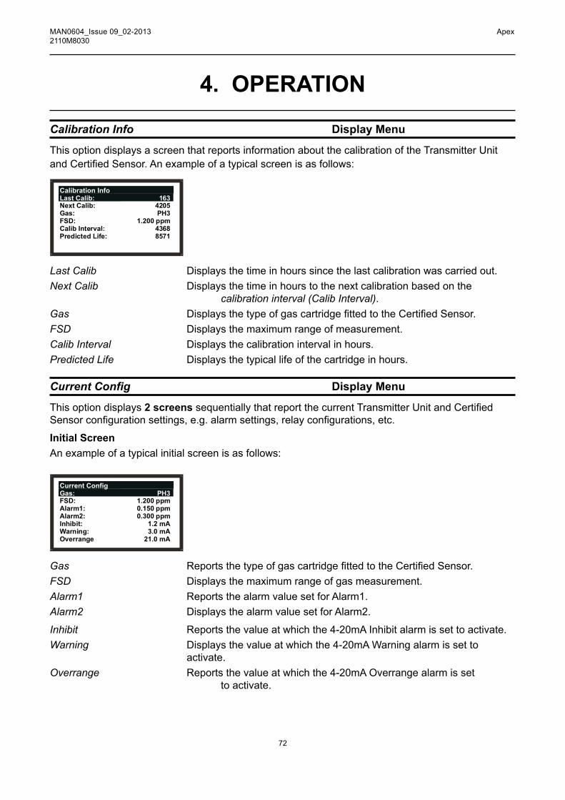
72
MAN0604_Issue 09_02-2013 Apex2110M8030
4. OPERATION
Calibration Info Display Menu
This option displays a screen that reports information about the calibration of the Transmitter Unit andCertifiedSensor.Anexampleofatypicalscreenisasfollows:
Calibration InfoLast Calib: 163Next Calib: 4205Gas: PH3FSD: 1.200 ppmCalib Interval: 4368Predicted Life: 8571
Last Calib Displays the time in hours since the last calibration was carried out.Next Calib Displays the time in hours to the next calibration based on the
calibration interval (Calib Interval).Gas DisplaysthetypeofgascartridgefittedtotheCertifiedSensor.FSD Displays the maximum range of measurement.Calib Interval Displays the calibration interval in hours.Predicted Life Displays the typical life of the cartridge in hours.
CurrentConfig Display Menu
This option displays 2 screenssequentiallythatreportthecurrentTransmitterUnitandCertifiedSensorconfigurationsettings,e.g.alarmsettings,relayconfigurations,etc.
Initial ScreenAnexampleofatypicalinitialscreenisasfollows:
Current ConfigGas: PH3FSD: 1.200 ppmAlarm1: 0.150 ppmAlarm2: 0.300 ppmInhibit: 1.2 mAWarning: 3.0 mAOverrange 21.0 mA
Gas ReportsthetypeofgascartridgefittedtotheCertifiedSensor.FSD Displays the maximum range of gas measurement.Alarm1 Reports the alarm value set for Alarm1.Alarm2 Displays the alarm value set for Alarm2.
Inhibit Reportsthevalueatwhichthe4-20mAInhibitalarmissettoactivate.Warning Displaysthevalueatwhichthe4-20mAWarningalarmissetto
activate.Overrange Reportsthevalueatwhichthe4-20mAOverrangealarmisset
to activate.

73
MAN0604_Issue 09_02-2013 Apex2110M8030
Second ScreenThe second screen is displayed after navigating past the last entry on the initial screen by using the down button.Atypicalexampleisasfollows:
Current ConfigFault Relay: NE/LAlarm1 Relay:
Tx Version: 1.02Sensor
NE/NLAlarm2 Relay: NE/NL
Version: 1.2
Fault Relay Reportsthecontactconfiguration(seeNote)fortheFaultRelay.Alarm1 Relay Displaysthecontactconfiguration(seeNote)fortheAlarm1Relay.Alarm2 Relay Reportsthecontactconfiguration(seeNote)fortheAlarm2Relay.Tx Version Displays the current version of the transmitter software.Sensor Version ReportsthecurrentversionoftheCertifiedSensorsoftware.
Note: The abbreviations used on the screen for the contact settings mean the following: nd Normally De-energised nE Normally Energised l Latching nl Non-Latching
4.4.4 History Log MenuThe History Log Menu enables the recorded log for the unit to be viewed by the operator and also reset, or cleared. The logcontains information about events that happen during the life of the TransmitterUnit,e.g.timeoflastCertifiedSensorcalibration,timeoflastalarm,etc.
This menu is protected by a Level 2 password.
4. OPERATION
History Log MenuView History LogReset History Log

74
MAN0604_Issue 09_02-2013 Apex2110M8030
4. OPERATION
View History Log History Log Menu
This sub-menu item displays screens that consist of one or more pages of information, each displaying a message, recording the history of the unit since the log was last reset. The most recent eventisviewedfirst.
History Page 32/61000038:16Tx AlertSensor Comms Error
To navigate through the unit's history use the up/down buttons to view different pages.
Note: Keep the button pressed continuously to quickly scroll through the pages of a large log record.
The top line of the message indicates the current page number and then the total number of pages in the log. An example is 22/45, i.e. 22nd page of 45 pages.
The next line contains the history clock time in hours and minutes since the event occurred. Each time you subsequently view this time therefore it will be different.
To calculate the date/time of a recorded event take the displayed time on screen away from the current date/time.
The next lines contain the text of the log recording the event.
After viewing the page(s) use the esc button to return to the History Log Menu.
Notes:
1. Thereisamaximumof64historyentries.Thefirstandsubsequentrecordedentriesareoverwrittenasthelogexceedsthisfigure.
2. The log time is not incremented when the unit is powered down.
Reset History Log History Log Menu
Caution: Resetting the log removes all recorded data and resets the history clock to zero. This option is used to clear the current message content of the history log.

75
MAN0604_Issue 09_02-2013 Apex2110M8030
Yes
Reset History Log
ok
Reset History Log screen
Use up/downbuttons
History Log Menu
Messages clearedfrom log
Are you sure?NoYes
No
4.4.5 Change Passwords Menu
The Change Passwords Menu allows the system administrator to change the passwords for each of the three levels of access.
This menu is protected by a Level 3 password.
4. OPERATION
Change Passwords MenuLevel 1 PasswordLevel 2 PasswordLevel 3 Password
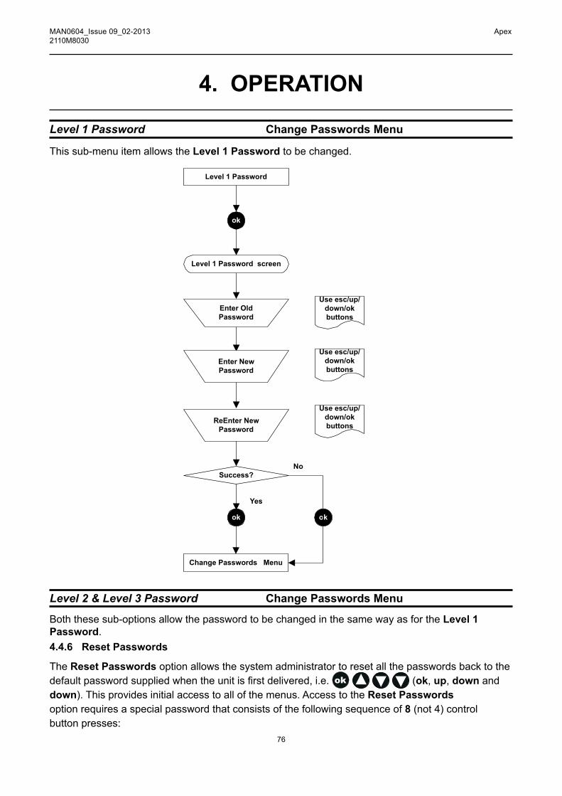
76
MAN0604_Issue 09_02-2013 Apex2110M8030
4. OPERATION
Level 1 Password Change Passwords Menu
This sub-menu item allows the Level 1 Password to be changed.
Level 2 & Level 3 Password Change Passwords Menu
Both these sub-options allow the password to be changed in the same way as for the Level 1 Password.4.4.6 Reset Passwords
The Reset Passwords option allows the system administrator to reset all the passwords back to the defaultpasswordsuppliedwhentheunitisfirstdelivered,i.e. (ok, up, down and down). This provides initial access to all of the menus. Access to the Reset Passwords option requires a special password that consists of the following sequence of 8 (not 4) control buttonpresses:
Level 1 Password
ok
Enter Old
Password
Level 1 Password screen
Change Passwords Menu
Use esc/up/
down/ok
buttons
Enter New
Password
ReEnter New
Password
Use esc/up/
down/ok
buttons
Use esc/up/
down/ok
buttons
ok
Success?
Yes
No
ok

77
MAN0604_Issue 09_02-2013 Apex2110M8030
4. OPERATION
(up, down, ok, esc, esc, ok, down, up)
4.5 USER TASKSThe following table provides a quick reference list of typical tasks and how to carry them out via the menu system.
Tasks related to: Sub-Menu Sub-Menu Option User Level4-20mA loop SetInhibit,WarningandOverrangelevels Configuration Configure4-20mA 2 Zerosetting Calibration 4-20mASetZero 2 Testoperation Calibration Force4-20mA 2Alarms Setoverrangelatchingonoroff Configuration ConfigureAlarms 2 Setgasalarmlevels Configuration ConfigureAlarms 2 Reset alarms Display Reset Alarms 1Checking the unit’s settings Calibration settings Display Calibration Information 1 Configurationsettings Display CurrentConfiguration 1Checking the unit’s operational history View the unit's log History Log View History Log 2 Clearing the history log History Log Reset History Log 2Digital communications Viewsettings ConfigurationConfigureDigital 2 Registerthecommunicationsboard ConfigurationConfigureDigital 2 Test operation Calibration Force Digital 2Display Screen Turnbacklighton/off* Configuration ConfigureBacklight 2Changetheon-screendisplaylanguage Configuration SelectLanguage 2gas Test unit with gas Calibration Gas Challenge 2 Changeagassensorcartridge Configuration ChangeCartridge 2 Calibrate gas Calibration Gas Calibrate 2Passwords Change a password Change Passwords Level 1 Password 3 Change Passwords Level 2 Password 3 Change Passwords Level 3 Password 3 Reset all passwords to default Reset passwords 3Relays Set-uprelaycontacts Configuration ConfigureRelays 2 Test relays Calibration Force Relays 2
* The Configure Backlight controlisnotavailableonCSACertifiedTransmitterUnits.

78
MAN0604_Issue 09_02-2013 Apex2110M8030
4. OPERATION4.6 FAULT DIAGNOSISApex system faults can be those displayed on the Transmitter Unit screen or be of a general type. Thissectiondescribes:
• Error messages displayed on the Transmitter Unit LCD screen. These are either fault or warning types. They can normally be corrected at the Transmitter UnitorCertifiedSensor.
• Errors that are not diagnosed by the system itself but need some action.ForexampletheCertifiedSensorreadslowwhengasisapplied.Torectifythisfaultthecontrol system span needs to be adjusted.
• Signal ranges and fault conditions on the 4-20mA output. • How to clear latched alarms
4.6.1 Displayed Error MessagesTheerrormessagesontheLCDscreenaresimilartothefollowing:
F:No CartridgeFAULT Panels flash
alternately untilfault cleared
The following table lists all the displayed Fault (F) and Warning (W) messages.
Message Cause/Remedy
W: Sensor Failed F: Sensor Failed ACertifiedSensorfaulthasdeveloped. ChecktheconnectionsbetweentransmitterandCertifiedSensor. Re-calibratetheCertifiedSensor. IffaultremainsreplacethecompleteCertifiedSensorassembly.
F: No Cartridge TheCertifiedSensorreportsthereisnocartridgefitted. Checkthatthecartridgeisfittedcorrectly. Ifnocartridgepresent,fitrequiredcartridge.
F: Wrong Cartridge ThewrongtypeofcartridgehasbeenfittedintheCertifiedSensor. Replace the cartridge with correct type for the target gas.F: Cartridge Failed The cartridge has failed. Replace the cartridge.
W: Temperature Error Thecartridgeisbeingoperatedattemperaturesoutsideitsspecified F: Temperature Error temperature range. Identify the cause of temperature problem. FitsuitableaccessoriesorrelocatetheCertifiedSensorasappropriate. IffaultpersistsreplacetheCertifiedSensor.

79
MAN0604_Issue 09_02-2013 Apex2110M8030
W: End of Cell Life The cartridge is reaching, or has reached, the end F: End of Cell Life of its useful service life. Warning - replace the cartridge within the next 3 months. Fault - replace the cartridge immediately.W: Calibration Needed The cartridge requires calibration. F: Calibration Needed Performzeroandspancalibrationprocedures.
FATAl FAUlT A fatal error has occurred. Note the displayed fault code and conditions, and contact the manufacturer for advice.nO SEnSOR The transmitter can not detect the presence of the sensor.
Sensor comms Fail Sensor incorrectly connected or faulty. CheckconnectionsbetweenCertifiedSensorandtransmitterunit. Ifconnectionscorrectbutmessageremains,replaceCertifiedSensor.
4.6.2 General FaultsThe following table lists symptoms and causes for general fault diagnosis.
Gas Reading Symptom Cause/Remedy
Non-zero all the time Gas could be present, ensure that there is no target gas in the atmosphere.
Background or other volatile organic gases that may be present, e.g. solvents, caninterferewiththeoperationoftheCertifiedSensor.
Non-zero when no Adjustthesystemzero. gas is present (Calibration Menu => Gas Calibrate).Low when gas Adjust the system span concentration setting. is applied (Calibration Menu => Gas Calibrate).High when gas Adjust the system span concentration setting. is applied (Calibration Menu => Gas Calibrate).Zero when gas CheckthattheCertifiedSensorgasentryisnot is applied obstructed. Checkthatthesinterandanyfilter,iffitted,isnotblocked. Replace the cartridge. (Configuration Menu => Change Cartridge).
4. OPERATION

80
MAN0604_Issue 09_02-2013 Apex2110M8030
4. OPERATION
4.6.3 4-20mA output signal ranges and fault conditions
22..
20..
6
5
4
3
2
1
0.5
0
mA
Overrange
Warnings
Concentrations
Inhibit
Fault
Pulsed warnings
General Fault Output Signal Level Fault Conditions Type
Faults 0 - 0.5mA Sensor Failed (defaultis0.5mA) NoCartridge Wrong Cartridge Cartridge Failed Temperature Error End of Cell Life Calibration Needed No Sensor, Sensor Comms Fail Fatal Fault
Warnings 1.0 - 3.5mA - constant Temperature Error 4.0 - 6.0mA - pulsed 1/sec End of Cell Life (default is 3mA) Calibration Needed
Over range 20 - 21.5mA Gas Reading exceeded
Warnings (default is 21mA) full scale
Inhibit - Locks relays and outputs

81
MAN0604_Issue 09_02-2013 Apex2110M8030
4.6.4 Clearing latched alarms
4. OPERATION
The fault and alarm relays may be set to be latched (see ConfigurationMenu). So when an alarm message is displayed on the LCD screen it may continue to be displayed even when the fault causing the problem is corrected.
Note: Alarms may not be set to be latched, but because alarm recovery is set 25% below alarm setpoint it could appear that they are for a short while.
Toresetalatchedalarmcarryoutthefollowingprocedure:
(1) Press esc at the Gas Reading display.
The Main Menu is displayed.
Main MenuCalibration MenuConfiguration MenuDisplay MenuHistory Log MenuChange Passwords MenuReset Passwords
(2) Select (highlight) Display Menu from the list.
(3) Press ok.
(4) When prompted enter the current Level 1 password.
Obtain the password from the system administrator.
The Display Menu is shown.
Display MenuReset Alarms, FaultsCalibration InfoCurrent Config
(5) Select the Reset Alarms, Faults option.
(6) Press ok.
The Reset Alarms, Faults menu is displayed.
WARNING
! Alarms should not be reset until it is confirmed that gas is not present.
Reset Alarms, FaultsReset AlarmsFault Relay: InactiveAlarm1 Relay: Inactive
Relay: InactiveOverrange: InactiveAlarm2

82
MAN0604_Issue 09_02-2013 Apex2110M8030
4. OPERATIONThe menu displays the state of the fault and alarm relays and the overrange.
(7) Select Reset Alarms from the list.
(8) Press ok.
The display returns to the Display Menu.
Note: Alarms are not reset until the esc button is pressed to leave the Display Menu and return to the Main Menu.
4.7 SYSTEM CAliBRATiOnCaution: Thecalibrationprocedureshouldonlybeperformedbyqualifiedpersonnel.ThissectiondescribeshowtocalibratethegascartridgefittedtoanApexCertifiedSensor. The Transmitter Unit and other system components do not require calibration. This procedure is sometimes referred to as system or sensor calibration.
Cartridge are supplied from the factory fully calibrated for the target gas, re-calibration at commissioning/start-up should not normally be required, However, if operating this product inaccordancewithEN60079-29-2,oriflocal/nationalregulationsrequirethecartridgetobecalibrated this procedure should be followed. This procedure is also applicable if a cartridge requires re-calibration following a warning or fault message, or as part of routine maintenance
The calibration adjustments are carried out at the Transmitter Unit and gassing is performed at the CertifiedSensor(thismaybelocallyorremotelylocated).
Thefollowingequipmentisrequired:
• Flow Housing accessory (Part No: 2110B2140) -fittedwith rubbersealandsuppliedwithloosehydrophobicfilter
• Test gas • RegulatorNote: Zero gas and Span gas should be at roughly the same humidity levels to avoid erroneous cell
responses.
AhydrophobicfilterissuppliedloosewiththeFlowHousingwhichmust befittedwhencalibratingsensors with flammable gas cartridges.
Whencalibratingsensorsfittedwithother cartridge types thenthefiltermountedinthesensorcapfornormalgassensingoperation(ifonewasused)shouldbefittedtotheFlowHousing.

83
MAN0604_Issue 09_02-2013 Apex2110M8030
(1) AttheCertifiedSensorremovethecaporaccessory.
Sensor body
Filterlug location
Filter
Sensor capor accessory
Lug(3 off)
Rotate the cap/accessory in an anticlockwise direction by 1/4 turn to release the bayonet fittingandpulloff.
(2) If calibrating a sensor with a non-flammable gas cartridge removethefilter,iffitted,fromthesensorcap/accessoryandfitittotheFlowHousing.
Iffitted,thefilterisheldinplaceinthecap/accessorybyitsthreelugs.Carefullyprisethefilterfree from the lug location points in the cap or accessory.
If calibrating a sensor with a flammablegascartridgefitthehydrophobicfiltersupplied with the Flow Housing into the housing.
Ineithercase,tofitafilterintotheFlowHousing,firstremovethefactory-fittedsealfromtheFlow Housing. The seal is held in place in the housing by its three lugs. Carefully prise the seal free from the lug location points in the housing.
ThefilterthenlocatesintheFlowHousinginthesamewayastheremovedseal.EnsurethatthefilterisplacedintheFlowHousingthecorrectwayroundwiththethreelugsclosesttothefront face of the housing (where the gas pipes exit) and correctly engaged in the location points.
4. OPERATION
Filterlug location
Filter
Flow Housing
Lug(3 off)
(3 off)

84
MAN0604_Issue 09_02-2013 Apex2110M8030
4. OPERATION(3) FittheFlowHousingontotheCertifiedSensorbody.
Reverse the cap removal procedure. The following diagram shows the Flow Housing accessoryfittedtotheCertifiedSensor.
CertifiedSensor
FlowHousing
(4) Press the esc button at the Transmitter Unit.
The Main Menu is displayed.
Main MenuCalibration MenuConfiguration MenuDisplay MenuHistory Log MenuChange Passwords MenuReset Passwords
(5) Navigate to the Calibration Menu option.
Use the up/down keys.
(6) Press ok.

85
MAN0604_Issue 09_02-2013 Apex2110M8030
(7) Enter the current Level 2 password.
The Calibration Menu is displayed.
Calibration MenuGas CalibrateGas Challenge4-20 mA Set ZeroForce 4-20mAForce RelaysForce Digital
(8) Navigate to the Gas Calibrate option.
Use the up/down keys.
(9) Press ok.
The Zero Calibration screen is displayed with the message:
Zero Gas then <OK> (10) EnsurethereisnogaspresentontheCertifiedSensor.
If gas is suspected to be in the vicinity of the sensor either check the area using a calibrated portablegassensingdevice,e.g.HoneywellAnalytic'sImpact,orflowcleanairovertheCertifiedSensorusingtheFlowHousingaccessory.
(11) Press ok.
The Transmitter Unit zeros the sensor. The LCD screen displays the message:
Calibrating - WaitWhen successfully completed the LCD screen shows the message:
Success! OK:Continue(12) Press ok.
The Span Calibration screen is displayed with the message:
Calibrate? OK/ESCThis gives the choice to stop the calibration procedure at this point (after zero calibration) or continue to include the span and full gas calibration.
(13) Press ok to continue with Span Calibration.
To skip the span calibration process, press the esc key.
Note: Atthispoint,dependingonthetypeofgascartridgefittedtothesensor,achoiceoftwocalibration gases may be displayed, e.g. C7H8 has the options C7H8 and CH4 as choices. If so choose the one that will be used for calibration and press ok. Otherwise the process continues at the following step.
(14) Set the required test gas Span Conc. value.
Use the up/down keys.
4. OPERATION

86
MAN0604_Issue 09_02-2013 Apex2110M8030
4. OPERATION(15) Press ok.
The LCD screen displays the message:
Apply Gas then <OK>(16) Connect the Flow Housing (using either gas pipe) to the regulated cylinder containing a
knownconcentrationofthetargetgasatapproximatelythesensoralarmpoint,e.g.50%LELMethane in air.
It is recommended for most sticky gases the tubing should be PTFE with short pieces of rubbertubetomakethefinalconnectionduetotheinflexibilityofPTFE.Thisminimisesadhesion of the gas to the tube surface and allows for more accurate measurement.
WARNINGAs some test gases may be hazardous, the Flow Housing
outlet should exhaust to a safe area.!(17) ApplythetargetgastotheCertifiedSensor.
Passthegasthroughtheflowhousingatarateofbetween0.7l/mand1.0l/m.Waitforthe gas reading to stabilise before continuing
Note: CertifiedSensorsshouldbecalibratedatconcentrationsrepresentativeofthosetobemeasured.ItisalwaysrecommendedthattheCertifiedSensoriscalibratedwiththetargetgas it is to detect.
Caution: WheretheusercalibratesanyCertifiedSensor using a different gas, responsibility for identifying and recording calibration rests with the user. Refer to the local regulations where appropriate.
(18) Press ok.
The LCD screen displays the message:
Calibrating - Wait(19) Whencalibrationissuccessfullycompletedthemessageisdisplayed:
Success! OK:ContinueEnsure that the sensor and the vicinity around it is clear all traces of the calibration gas before continuing. This is to avoid triggering spurious alarms.
If calibration fails at any point discard the cartridge and replace with a new one (see Chapter 5).
(20) Pressok.
The Calibration Menu is displayed.
(21) Press the esc button twice.
The Main Menu and then the Gas Reading screen is displayed.
(22) Removethetestequipment,refitthesensorcaptothesensor(withreinstalledfilterifpreviously removed for the test) and return the system to normal operation (see 4.2).
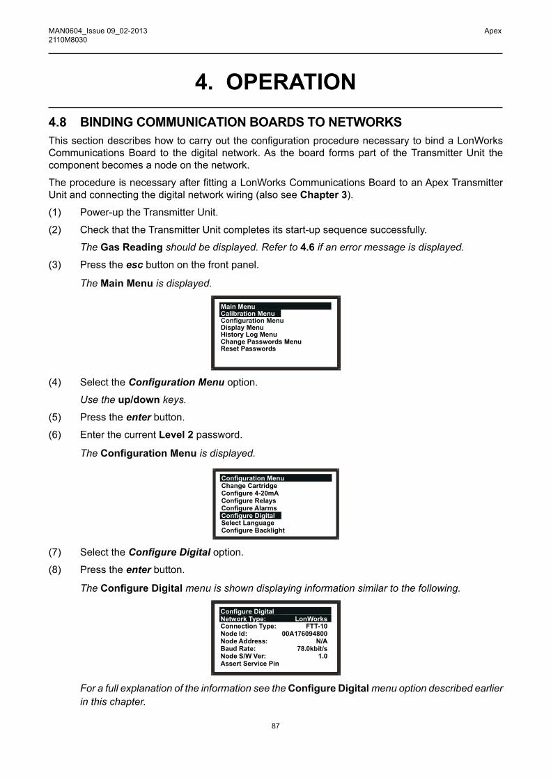
87
MAN0604_Issue 09_02-2013 Apex2110M8030
4.8 BINDING COMMUNICATION BOARDS TO NETWORKSThissectiondescribeshowtocarryouttheconfigurationprocedurenecessarytobindaLonWorksCommunications Board to the digital network. As the board forms part of the Transmitter Unit the component becomes a node on the network.
TheprocedureisnecessaryafterfittingaLonWorksCommunicationsBoardtoanApexTransmitterUnit and connecting the digital network wiring (also see Chapter 3).
(1) Power-up the Transmitter Unit.
(2) Check that the Transmitter Unit completes its start-up sequence successfully.
The Gas Reading should be displayed. Refer to 4.6 if an error message is displayed.
(3) Press the esc button on the front panel.
The Main Menu is displayed.
Main MenuCalibration MenuConfiguration MenuDisplay MenuHistory Log MenuChange Passwords MenuReset Passwords
(4) Select the ConfigurationMenu option.
Use the up/down keys.
(5) Press the enter button.
(6) Enter the current Level 2 password.
The Configuration Menu is displayed.
Configuration Menu
Configure Digital
Change CartridgeConfigure 4-20mAConfigure RelaysConfigure Alarms
Select LanguageConfigure Backlight
(7) Select the ConfigureDigital option.
(8) Press the enter button.
The Configure Digital menu is shown displaying information similar to the following.
Configure DigitalNetwork Type: LonWorksConnection Type: FTT-10Node Id: 00A176094800Node Address: N/ABaud Rate: 78.0kbit/sNode S/W Ver: 1.0Assert Service Pin
For a full explanation of the information see the Configure Digital menu option described earlier in this chapter.
4. OPERATION

88
MAN0604_Issue 09_02-2013 Apex2110M8030
(9) Select the Assert Service PIN option.
Use the up/down keys.
(10) Presstheenter button.
This binds the node to the network controller.
The display automatically returns to the Configuration Menu.
(11) Press the esc button twice
This returns to the Gas Reading display via the Main Menu.
4. OPERATION

89
MAN0604_Issue 09_02-2013 Apex2110M8030
5. MAINTENANCEThe Apex system requires some routine maintenance.
Thissectionprovidesinformationaboutthefollowing:
• Schedule for routine maintenance
• Procedures for routine maintenance/parts replacement
5.1 ROUTINE MAINTENANCE SCHEDULEThe following table lists the recommended Apex system maintenance tasks and their frequency.
Sensor Type Frequency Maintenance Action Equipment Required
All models On overrange Calibrate the Test gas, gas alarm system (see regulator, Chapter4). flow Replace the sensor housing. cartridge if necessary. All models On suspected Calibrate the Test gas, exposure to system (see regulator, contaminating Chapter4). flow gases Replace the sensor housing. cartridge if necessary. All models 3monthly Checkthefilters/cartridge face for cleanliness. Replace if required.
All models 6 monthly Calibrate the Test gas, system (see regulator, Chapter4). flow housing.Cl2, O2, and NH3 Annually Replace the sensor cartridge if required. H2S, CO 2 yearly Replace the sensor cartridge if required.
Note: NoroutinecalibrationisrequiredfortheTransmitterUnitorCertifiedSensorelectronics. Only the cartridge can be re-calibrated. This procedure is also sometimes referred to as system or sensor calibration.

90
MAN0604_Issue 09_02-2013 Apex2110M8030
5. MAINTENANCE5.2 MAINTENANCE PROCEDURES /PARTS REPLACEMENTThe following sections describe how to carry out the tasks listed in the maintenance schedule and how to replace parts suggested by Fault Diagnosis in Chapter 4. It tells how to change the followingitems:
• Certified Sensor Filter • Certified Sensor Cartridge • Certified Sensor • Transmitter Unit Front Panel Assembly • CSA Transmitter Unit User Interface Cover Assembly
5.2.1 Changing the Certified Sensor FilterTheCertifiedSensorfilterislocatedinthesensorcaporaccessoryattachedtotheendofthesensorbody.Thisprocedureallowsthefiltertobesafelychangedwiththeunitpowered-up.
Note: Beforestartingtheprocedurecheckthatthenewfilteristhecorrecttypefortheapplication.Threefiltertypesareavailable:Mesh,HydrophobicandCarbon(seeChapter 2 and Appendix C).
Toreplacethefiltercarryoutthefollowingprocedure:
(1) RemovetheCertifiedSensorcaporaccessoryfromthesensorbody.
Rotate the cap or accessory in an anticlockwise direction by 1/4 turn to release the bayonet fittingandpulloff.
(2) Removetheexistingfilter.
Thefilterisheldinplaceinthecapbyitsthreelugs.Carefullyprisethefilterfreefromtheluglocation points in the cap or accessory.
Sensor body
Filterlug location
Filter
Sensor capor accessory
Lug(3 off)

91
MAN0604_Issue 09_02-2013 Apex2110M8030
(3) Insertanewfilter.
Ensurethatthefilteriscorrectlyplacedinthecapthecorrectwayroundwiththethreelugsclosest to the front face of the cap or accessory and correctly engaged in the location points.
(4) Refitthecaporaccessory.
Reverse the removal procedure.
5.2.2 Changing the Certified Sensor Cartridge
WARNINGSChange cartridges using the procedure described below.Failure to correctly follow this procedure could result in thewrong cartridge being installed, and possibly non-detectionof events. Alternatively, extraneous alarms could betriggered by chemicals detected but not of concern at aparticular location.
Sensor Cartridges may contain corrosive solutions.Dispose of according to local and national regulations.
!
TheCertifiedSensorcartridgeislocatedinthesensorbody and protected by the cap or accessory. This procedure allows the cartridge to be safely changed with the unit powered-up.
Eachcartridgeisprovidedwithacertificateofcalibration(printed onthereverseoftheinstructionsheet,PartNo:2110M8015, supplied with the cartridge) that guarantees that the cartridge is calibrated and ready for use.
Before installing a cartridge check that the number on the cartridge label matches the gas type and range for the function required. A list of cartridges is given in Appendix A.
Toreplaceacartridgecarryoutthefollowingprocedure:
(1) Press esc at the Gas Reading display.
The Main Menu is displayed.
Main MenuCalibration Menu
Display MenuHistory Log MenuChange Passwords MenuReset Passwords
Configuration Menu
(2) Select ConfigurationMenu from the list.
(3) Press ok.
(4) Enter the current Level 2 password.
For information about passwords see Chapter 4.
The Configuration Menu is displayed.
5. MAINTENANCE

92
MAN0604_Issue 09_02-2013 Apex2110M8030
5. MAINTENANCE
Configuration MenuChange CartridgeConfigure 4-20mAConfigure RelaysConfigure AlarmsConfigure DigitalSelect LanguageConfigure Backlight
(5) Select Change Cartridge from the menu list.
(6) Press ok.
The Change Cartridge screen is displayed.
Change Cartridge
Change Cartridge Now
Cartridge: Present
Whilst this screen is showing, the cartridge can be safely replaced with the unit powered-up as follows.
(7) RemovetheCertifiedSensorcaporaccessoryfromthesensorbody.Rotate the cap or accessory 1/4 turn in an anticlockwise direction to release the bayonet fitting.
(8) Remove the existing cartridge.
ThecartridgeplugsintotwosocketsintheCertifiedSensorbodyandislocatedbymeansofa tab.
To remove the cartridge without damaging it, grasp the visible part of the cartridge and pull it firmlystraightoutofthesensorbodywithouttwisting.Slightresistanceisinitiallyfeltasthecartridge is pulled out of the electrical sockets.
Sensorbody
Sensorcap

93
MAN0604_Issue 09_02-2013 Apex2110M8030
Notes:
1. If replacing an Oxygen cartridge with another Oxygen cartridge ensure that the Oxygen TransducerAdaptorisleftinplaceontheCertifiedSensorbody.
2. If replacing an Oxygen cartridge with a different type of cartridge ensure that the Oxygen Transducer Adaptor is removed from the sensor body.
3. If replacing a standard cartridge with an Oxygen cartridge ensure that the Oxygen Transducer AdaptorsuppliedwiththeOxygencartridgeisfittedtotheCertifiedSensorbody.Theadaptorisfittedtothesensorbodyviaabayonetfitting.
The Change Cartridge screen now displays the following message.
Change Cartridge
Change Cartridge Now
Cartridge: Not Present
(9) Fit the replacement cartridge.
Caution: OnlycartridgeswiththefollowingpartnumberscanbefittedtotheCertifiedSensor:
2110B30x0, 31x0, 32x0, 33x0, 34x0, 35x0 series 2110B3700 - 2110B3999 rangeNotes:
1. CertifiedtoCSA 22.2 No. 152onlywhenfittedwithspecificcartridges. SeeSpecificationsfordetails.
CarefullyplugthecartridgeintotheCertifiedSensorbodyensuringthatthecartridgetab lines up with the recess in the sensor body and push the cartridge, without twisting, until it is fully home.
If the cartridge will not push fully home, re-check that the locating tab is correctly aligned with the recess in the sensor body. Position the tab so it is resting on the tab recess wall to the right or left of the tab recess and then turn the cartridge until the tab drops into the recess.
Caution: Do not force the cartridge as this may cause damage to the pins of the connecting plugs. Twisting and pushing can bend the pins and make the cartridge inoperative.
5. MAINTENANCE

94
MAN0604_Issue 09_02-2013 Apex2110M8030
5. MAINTENANCE
Socket (2 off)
Locatingtab
recess
Sensor body
Plug(2 off)
Locatingtab
Cartridge
(10) Pressok.
The Change Cartridge screen now displays the following message.
Change CartridgeWorkingPlease Wait
This screen is displayed while the cartridge is checked by the Transmitter Unit.
When the checks are completed successfully the following type of information about the new cartridge is displayed on the screen.
Change CartridgeNew Cartridge TypeGas: HFFSD: 12.00 ppmAlarm1: 1.50ppmAlarm2: 3.00ppm
Checkthattheinformationdisplayedcorrespondstothetypeofreplacementcartridgefitted.
(11) Press ok.
The Change Cartridge screen now displays the following message.
Change CartridgeSuccess! OK: Continue
(12) Press ok.
The screen display returns to the Configuration Menu.
(13) Press esc twice.
The screen returns to the Gas Reading display.

95
MAN0604_Issue 09_02-2013 Apex2110M8030
(14) RefitthecaporaccessorytotheCertifiedSensor.
Reverse the removal procedure.
(15) Check that the system is working correctly.
Use the Calibration Menu => Gas Challenge menu option to check correct operation of the unit in the presence of the gas being sensed without triggering alarms, etc. (see Chapter 4).
Apply gas using a gas test module.
(16) Return the system to normal operation.
5.2.3 Changing the Certified Sensor TheCertifiedSensormaybemountedinaTransmitterUnitor remotelyinaCertifiedJunctionBox.Whenreplacing certifiedcomponentsalsorefertotheControlDrawings (see Appendix B).
ToreplaceaCertifiedSensorfittedtoaTransmitterUnitora CertifiedJunctionBoxcarryoutthefollowingprocedure:
Caution: EnsurethattheTransmitterUnit/Certified JunctionBoxflamepathisnotdamagedduring thisprocedure.Theflamepathisformedbythe matingsurfacesoftheTransmitterUnit/Certified JunctionBoxtopandbase(seethecomponent diagrams in Chapter 3).
(1) Isolate all associated power supplies and ensure that they remain OFF during this procedure. Ensure a gas free atmosphere.
Transmitter Unittop
Top fixing screw(3 off)
o
Certified JunctionBox top
Metalretaining
cableMetal retaining
cable
(2) DetachtheTransmitterUnitorCertifiedJunctionBoxtop.
Unscrew the three captive M8 hexagon key bolts underneath the base. Lift the top clear. For the Transmitter Unit only lift the top clear of the locating pins.
5. MAINTENANCE

96
MAN0604_Issue 09_02-2013 Apex2110M8030
5. MAINTENANCECaution: For the Transmitter Unit only take care not to damage or strain the ribbon cable
connectingthelidandtheInterconnectPCBinthebaseoftheunit.
(3) For the Transmitter Unit support the top and ensure that it is supported whilst the next two steps are carried out.
FortheCertifiedJunctionBoxletthemetalretainingcable,attachingthebaseandthetop,hold the top, then go to Step (7).
(4) UnlatchtheribboncableZeroInsertionForce(ZIF)connectorontheTransmitterUnitInterconnect PCB.
Grip the ends of the ZIF and pull it vertically upwards until it is felt to stop and the ribbon cable is loose. Refer to the Transmitter Unit installation component diagrams in Chapter 3.
(5) Pull the ribbon cable clear.
(6) Remove the support from the Transmitter Unit top.
Let the metal retaining cable, attaching the base and the top, hold the top.
(7) DisconnecttheCertifiedSensorwiring.
RemovethewiringfromtheterminalblocksontheInterconnectPCBinthebaseoftheTransmitterUnitorCertifiedJunctionBox.
Record the location of the sensor wiring in the terminal blocks.
(8) UnscrewtheCertifiedSensorfromitsmountingpoint.
CertifiedSensor mounting
point
CertifiedSensor

97
MAN0604_Issue 09_02-2013 Apex2110M8030
5. MAINTENANCE The sensor unscrews in an anticlockwise direction. Feed the connecting cable out through the
mounting point.
(9) FeedthecablefromthereplacementCertifiedSensorinthroughthesensormountingpoint.
(10) FitthereplacementCertifiedSensor.
ScrewthethreadedendofthereplacementCertifiedSensorfirmlyintothemountingpointuntil it is fully home.
(11) Cut the sensor cable to the required length.
(12) Connect the sensor wiring to the terminals.
Refer to the wiring notes recorded in step 3 and to the diagram and wiring tables in Chapter 3.
(13) RefitthetoptotheTransmitterUnitorCertifiedJunctionBoxbase.
Cautions: 1. Ensurethatthereisnomoistureinsidetheunitbeforefittingthelid.2. Use only the captive bolts supplied, replacement with alternative bolts will invalidate
certification.3. For the Transmitter Unit take care not to damage or strain the ribbon cable connecting
the lid and the base.The Transmitter Unit top should be aligned using the locating pins on the base and then loweredontothebase.TheJunctionBoxbasedoesnothavethelocatingpins.
Ensure that the lid retaining cable and/or wiring are not trapped and the O-ring in the top is correctly located. Check that there is no discernible gap between the top and the base.
Tighten the captive M8 bolts to 5Nm (3.68 foot-pounds).
Note: Ifthereplacementsensoristobefittedwiththeoriginalgassensingcartridge,thenremovethecartridgefromthereplacedsensorandfitittothenewonefollowingsimilarprocedurestothose in the sub-section 5.2.2.
(14) Switch on all associated power supplies.
(15) Check that the system is working correctly.
Use the Calibration Menu => Gas Challenge menu option to check correct operation of the unit in the presence of the gas being sensed without triggering alarms, etc. (see Chapter 4).
Apply gas using a gas test module.
(16) Return the system to normal operation.
See Chapter 4.

98
MAN0604_Issue 09_02-2013 Apex2110M8030
5. MAINTENANCE5.2.4 Changing the Transmitter Unit Front Panel AssemblyThis assembly may need to be replaced if the screen becomes damaged or the display and buttons donotoperatecorrectly.OneofthefollowingtwotypesofFrontPanelAssemblymaybefitteddependingontheTransmitterUnitversion:
• CSA Transmitter Unit Front Panel Assembly 2110B2825 • All other versions 2110B2820
The assembly is attached to the top of the Transmitter Unit by two screws.
To replace the assembly carry out the following procedure.
(1) Isolate all associated power supplies and ensure that they remain OFF during this procedure. Ensure a gas free atmosphere.
(2) Unscrew the two Front Panel Assembly retaining screws.
Use a hex-key tool to loosen the captive M4 screws.
(3) Pull the Front Panel Assembly forward away from the top.
TemporarilyrefittheM4hex-keytooltooneoftheretainingscrewsandgentlylevertheassembly out of the recess in the top.
(4) Discard the removed Front Panel Assembly.
(5) Place the replacement assembly into the recess in the top of the Transmitter Unit.
(6) Secure the two retaining screws.
Tighten to 2.0Nm.
(7) Switch on all associated power supplies.
(8) Check that the system is working correctly.
Ensure that the LCD screen is displaying a valid Gas Reading (see Chapter 4). Carry out a short random check of the menu system to ensure the front panel buttons are working correctly and the Transmitter Unit is responding and the LCD Screen is showing the correct information.
(9) Return the system to normal operation.
See Chapter 4.
esc
ok
Retaining screws
Apex topFront PanelAssembly

99
MAN0604_Issue 09_02-2013 Apex2110M8030
APPENDIX A - SPECIFICATIONSThissectionofthehandbookprovidesspecificationinformationaboutthefollowingcomponents:
• Transmitter Unit • Certified Sensor • Cartridges • Accessories
• LonWorks Communication Board
A.1 TRAnSmiTTER UniT And SEnSORTheApexTransmitterUnitisdesignedtooperatewiththeCertifiedSensorsspecifiedinthetableslaterinthissection.TheCertifiedSensorsaredesignedsothattheyallhaveacommonelectricalinterface to the Transmitters Unit. The cartridge data is digitised and processed into a gas reading bytheCertifiedSensor.ThedecisiononwhethergasalarmsarepresentisalsomadewithintheCertifiedSensor.
A.1.1 Gases and RangesTheTransmitterUnitwithCertifiedSensorcanbefittedwithanyofthecartridgeslistedinthetablesin section A.2.
A.1.2 Input/OutputPowersupply: +24VDCnominal(18-32V).Totalpowersupplyloopresistanceshould
belessthan30ohmswithECCcartridge,16ohmswithCatalyticcartridge.
Powerconsumption: Relaysactive-3.6WECCcartridge,5.6WCatalyticcartridge.
Relays: Threerelays:A1,A2andFault. Contactrating:100mA(min),2A(max)at30Vdcnon-inductiveexceptUL/CSAwherespecificationis+28VDC1A.
Singlepolechange-overtypeconnectedtotwoterminals:
• oneterminalconnectedtotherelaycommon • oneterminalconnectedviaauserconfigurablelinktoeitherthe
relay contact normally open or normally closed.
Relaysareuserconfigurabletobenormallyenergisedornormally de-energised.
Relaysareuserconfigurabletobelatchingornon-latching.Latchedrelays can be reset by the keypad, by the digital communications link (optional) or by the removal of power.
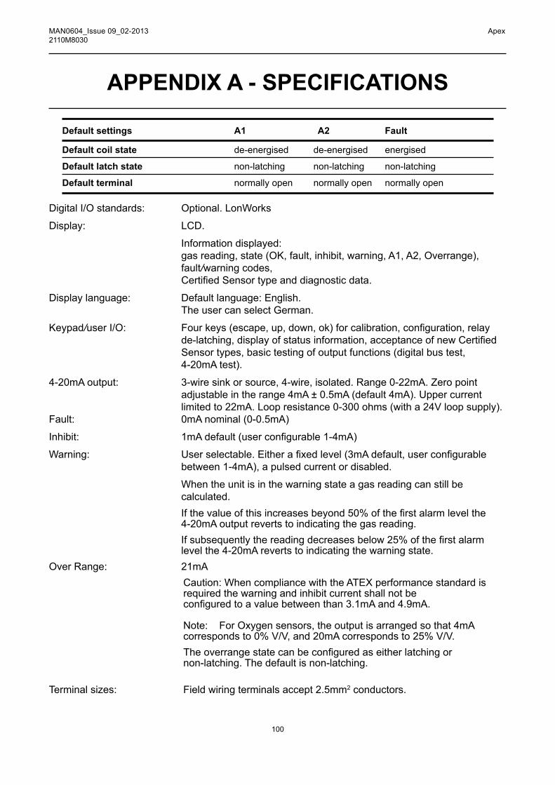
100
MAN0604_Issue 09_02-2013 Apex2110M8030
APPENDIX A - SPECIFICATIONS
Default settings A1 A2 Fault
Default coil state de-energised de-energised energised
Default latch state non-latching non-latching non-latching
Default terminal normally open normally open normally open
DigitalI/Ostandards: Optional.LonWorks
Display: LCD.
Informationdisplayed: gas reading, state (OK, fault, inhibit, warning, A1, A2, Overrange), fault/warning codes, CertifiedSensortypeanddiagnosticdata.
Displaylanguage: Defaultlanguage:English. The user can select German.
Keypad/userI/O: Fourkeys(escape,up,down,ok)forcalibration,configuration,relayde-latching,displayofstatusinformation,acceptanceofnewCertifiedSensor types, basic testing of output functions (digital bus test, 4-20mAtest).
4-20mAoutput: 3-wiresinkorsource,4-wire,isolated.Range0-22mA.Zeropointadjustableintherange4mA±0.5mA(default4mA).Uppercurrentlimitedto22mA.Loopresistance0-300ohms(witha24Vloopsupply).
Fault: 0mAnominal(0-0.5mA)
Inhibit: 1mAdefault(userconfigurable1-4mA)
Warning: Userselectable.Eitherafixedlevel(3mAdefault,userconfigurablebetween 1-4mA), a pulsed current or disabled.
When the unit is in the warning state a gas reading can still be calculated.
Ifthevalueofthisincreasesbeyond50%ofthefirstalarmlevelthe 4-20mAoutputrevertstoindicatingthegasreading.
Ifsubsequentlythereadingdecreasesbelow25%ofthefirstalarmlevelthe4-20mArevertstoindicatingthewarningstate.
OverRange: 21mA Caution:WhencompliancewiththeATEXperformancestandardis required the warning and inhibit current shall not be configuredtoavaluebetweenthan3.1mAand4.9mA. Note:ForOxygensensors,theoutputisarrangedsothat4mA correspondsto0%V/V,and20mAcorrespondsto25%V/V. Theoverrangestatecanbeconfiguredaseitherlatchingor non-latching. The default is non-latching. Terminalsizes: Fieldwiringterminalsaccept2.5mm2 conductors.

101
MAN0604_Issue 09_02-2013 Apex2110M8030
A.1.3 Monitoring functions Maintains a record of power ups in the Transmitter Unit. Maintains a time-stamped record of faults, warnings and alarms in the Transmitter Unit (history log).
A.1.4 Performance TransmitterUnitandCertifiedSensorwithoutcartridge.Accuracy: ±1%FSD-25to55°C(-13to131°F)Baselinedrift: ±0.5%FSDoverthreemonthsSpandrift: ±0.5%FSDoverthreemonthsBaselinevstemperature ±1%FSD-40to65°C(-40to149°F)Spanvstemp ±1%FSD-25to55°C(-13to131°F)Speedofresponse: <0.5sbetweenastepinputandacorrespondingchangeintheoutput.
DigitalelectronicsandsoftwaremeettherequirementsofEN50271:2002,Electricalapparatusforthedetectionand measurement of combustible gases, toxic gases or oxygen – Requirements and tests for apparatus using software and/or digital technologies.
Note: ForperformancespecificationofcompleteApextransmitter+Sensor+Cartridgerefertosection A.2 or data sheet for cartridge
A.1.5 EnvironmentalOperatingtemperature: -40to65°C(-40to149°F)UserInterface: -20to65°C(-4to149°F)Operatinghumidity: 0-99%rh
A.1.6 Storage (excluding cartridge)Temperature: -40to65°C(-40to149°F)
Humidity: 0-99%rh
A.1.7 EMCMeetstherequirementsofEN50270(type2apparatus),EMC-ElectricalApparatusfortheDetection and Measurement of Combustible Gases, Toxic Gases or Oxygen.
APPENDIX A - SPECIFICATIONS

102
MAN0604_Issue 09_02-2013 Apex2110M8030
APPENDIX A - SPECIFICATIONSA.1.8 EnclosurePhysical: TheTransmitterUnithas: OnethreadedholeinthebaseformountingtheCertifiedSensor
-M20(European)or3/4”NPT(NorthAmericanversions) TwothreadedholesinthebasetoaccepttwocertifiedM25cable
glands (European) or two 3/4”NPTconduitfittings(NorthAmericanversions).
Provision is made to attach a tag carrying an ID number. The enclosure materials for Apex are electro-polished grade 316
stainless steel (to BS3146 ANC 4B FM/BS3146 ANC 4C FM) and ZincAlloy.
Size: 140mmwidex150mmhighx152mmdeep.Weight: 4000gm.Mountings: ProvisionfortwoM10bolts,centres68mmapart.IngressProtection IP67toBSEN60529:1992,Degreesofprotectionprovidedby(Transmitter Unit with enclosures (IP code).CertifiedSensorfitted) A.1.9 ConfigurationTheTransmitterUnitcanbeconfiguredduringinstallationandoperationtoacceptanyoftheCertifiedSensorsitiscompatiblewith(seethegas/cartridgetablesinsectionA.2).
A.1.10 Certification and Approvals
Hazardous Area CertificationsTransmitter Unit:ATEX: II 2 G D Ex d ia IIC Ex tD A21 IP67
Operatingtemperaturecodes: T135°C(Tamb-40to+80°C)
T100°C(Tamb-40to+55°C)
Baseefa08ATEX02523
UL: Approvals by UL
Class I, Division 1, Groups B, C, D Operatingtemperaturecodes: T4(Tamb-40to+80°C) T5(Tamb-40to+55°C)
CSA: Approvals by CSA
Class I, Division 1, Groups B, C, D T4(Tamb-40to+75°C) T5(Tamb-40to+55°C)
TransmitterUnitCertifiedtoCSA C22.2 No. 152onlywhenCertifiedSensorisfittedwithspecificcartridges. See A.2 Cartridges, Flammable SG16 - US/Rest of the worldversion(page108).

103
MAN0604_Issue 09_02-2013 Apex2110M8030
CertifiedSensor:ATEX: II 2 G D Ex d ia IIC Ex tD A21 IP67
Operatingtemperaturecodes: T135°C(Tamb-40to+80°C) T100°C(Tamb-40to+55°C)
CertificationNumber:Baseefa08ATEX0254X
UL: Approvals by UL
Class I, Division 1, Groups B, C, D Operatingtemperaturecodes: T4(Tamb-40to+80°C) T5(Tamb-40to+55°C)
CSA: Approvals by CSA
Class I, Division 1, Groups B, C, D T4(Tamb-40to+75°C) T5(Tamb-40to+55°C)
CertifiedSensorapprovedtoCSA C22.2 No. 152onlywhenfittedwithspecificcartridges. SeeA.2Cartridges,FlammableSG16-US/Restoftheworldversion(page108).
CE MarkingComplieswithEUdirectives2004/108/EC(ElectromagneticCompatibility).
ComplieswithEN50270,EMC-ElectricalApparatusfortheDetectionandMeasurementofCombustible Gases, Toxic Gases or Oxygen
ComplieswithEUdirective94/9/EC(ATEX)foruseinHazardousAreas.
APPENDIX A - SPECIFICATIONS

104
MAN0604_Issue 09_02-2013 Apex2110M8030
APPENDIX A - SPECIFICATIONSA.1.11 Calibration intervalsCartridgedependent.ThereisnoroutinecalibrationoftheTransmitterUnitorCertifiedSensorelectronics.
A.2 cARTRidgES TheCertifiedSensorcanbefittedwithanyoneofanumberof
interchangeable cartridges. Each replaceable cartridge contains a gas sensing transducer and its calibration/manufacturing information. It is possible to replace the cartridge without removing the power from the CertifiedSensor,eveninhazardousenvironments.
Threetypesofcartridgeareavailable:
• electrochemical cell • catalytic (SG16 type) • Oxygen

105
MAN0604_Issue 09_02-2013 Apex2110M8030
A.2.1 Cartridge tablesThissectionprovidesasummarylistofthecartridgesthatcanbefittedtotheCertifiedSensor.Notes:
1. Consult Honeywell Analytics for cartridge availability.2. Forcartridgespecificationsseethedatasheetsuppliedwitheachcartridge.
Toxic - Electrochemical cellGas Range Part No:Ammonia 50ppm 2110B3320 Ammonia 100ppm 2110B3330 Ammonia 400ppm 2110B3340 Ammonia 1000ppm 2110B3350 Ammonia 50ppm(-20°Cmintemp)2110B3570 Ammonia 100ppm(-20°Cmintemp)2110B3540Ammonia 400ppm(-20°Cmintemp)2110B3550Ammonia 1000ppm(-20°Cmintemp)2110B3560
Borontrichloride 6ppm 2110B3020Bromine 0.4ppm 2110B3040
Carbonmonoxide 100ppm 2110B3140Carbonmonoxide 200ppm 2110B3150Carbonmonoxide 500ppm 2110B3160Chlorine 2ppm 2110B3090Chlorine 5ppm 2110B3100Chlorine 15ppm 2110B3110Chlorinedioxide 0.4ppm 2110B3130
Dichlorosilane 10ppm 2110B3430
Ethyleneoxide 25ppm 2110B3052
Fluorine 4ppm 2110B3200
Germane 0.8ppm 2110B3210
Hydrogen 1000ppm 2110B3220Hydrogenbromide 12ppm 2110B3270Hydrogenchloride 20ppm 2110B3280Hydrogencyanide 20ppm 2110B3290Hydrogenfluoride 12ppm 2110B3300Hydrogensulfide 15ppm 2110B3530Hydrogenselenide 0.2ppm 2110B3260Hydrogensulfide 20ppm 2110B3230Hydrogensulfide 50ppm 2110B3240Hydrogensulfide 100ppm 2110B3250
Nitricoxide(NO) 100ppm 2110B3360Nitrogendioxide 12ppm 2110B3370
Oxygen 21%V/V 2110B3380
Phosphine 1.2ppm 2110B3400 PropyleneOxide 50ppm 2110B3072
APPENDIX A - SPECIFICATIONS

106
MAN0604_Issue 09_02-2013 Apex2110M8030
APPENDIX A - SPECIFICATIONSSilane 2ppm 2110B3490Silane 20ppm 2110B3440Sulfurdioxide 8ppm 2110B3460Sulfurdioxide 10ppm 2110B3580Sulfurdioxide 15ppm 2110B3470Sulfurdioxide 50ppm 2110B3520
Flammable - Catalytic SG16 - European versionCalibrated to the %LEL levels required by EN 61779
Gas Range Part No:
1*(seenote) 100%LEL 2110B39102*(seenote) 100%LEL 2110B39113*(seenote) 100%LEL 2110B39124*(seenote) 100%LEL 2110B39135* 100%LEL 2110B39146* 100%LEL 2110B39157* 100%LEL 2110B39168* 100%LEL 2110B3917Butane 100%LEL 2110B3702Ethylene(seenote) 10%LEL 2110B3787Ethylene 100%LEL 2110B3708Hydrogen 100%LEL 2110B3707LPG 100%LEL 2110B3705Methane 100%LEL 2110B3704Propane 100%LEL 2110B3701Propene 100%LEL 2110B3703
Note: Cartridge must beusedwithApexrevisedCertifiedSensorPartNos: ATEX 2110B2070
UL 2110B2073 CSA 2110B2074
Flammable - Catalytic SG16 - US/Rest of the world version

107
MAN0604_Issue 09_02-2013 Apex2110M8030
Calibratedtothe%LELlevelsspecifiedbyCSA
Gas Range Part No:1 2(seenote) 100%LEL 2110B39302 2(seenote) 100%LEL 2110B39313 2(seenote) 100%LEL 2110B39324 2(seenote) 100%LEL 2110B39335 2 100%LEL 2110B39346 2 100%LEL 2110B39357 2 100%LEL 2110B39368 2 100%LEL 2110B3937Butane 2 100%LEL 2110B3752Ethylene 2 100%LEL 2110B3758Hydrogen 2 100%LEL 2110B3757Methane 2 100%LEL 2110B3754Propane 2 100%LEL 2110B37512 Evaluated to CSA C22.2 No.152.
Note: Cartridge must beusedwithApexrevisedCertifiedSensorPartNos: ATEX 2110B2070 UL 2110B2073 CSA 2110B2074
APPENDIX A - SPECIFICATIONS

108
MAN0604_Issue 09_02-2013 Apex2110M8030
APPENDIX A - SPECIFICATIONSA.2.2 Catalytic SG16 cartridges, Methane and Propane Range: 2110B3701-Propane,0to100%LEL. 100%LELeq.1.7%V/V) 2110B3704-Methane,0to100%LEL. (100%LELeq.4.4%V/V)
OperatingTemperatureRange: -40to+65°C
TemperatureEffects: 2110B3704–Methane,Betterthan+/-5%LEL 2110B3701–Propane,+/-6%LEL
OperatingHumidityRange: 5%rHto90%rH(99%rH Intermittent–non-condensing.)
HumidityEffects: Betterthan+/-5%LEL.
OperatingPressureRange: 80kPato110kPa
PressureEffects: Betterthan+/-5%LEL.
Warm-upTime: 30s(typical).900s(worstcase).
ResponseTime: 2110B3701–Propane,T50 8s, T90 17s. (typical)
2110B3704–Methane,T50 6s, T90 11s. (typical)
(Whenfittedwithstandardsensorcap andnofilter.)
Linearity: Betterthan+/-5%LELor+/-10% reading, whichever is the greater.
Accuracy/Repeatability: Betterthan+/-3%LEL
StabilitywithTime(3months): 2110B3704–Methane, Better than +/-5% LEL
2110B3701–Propane,+/-6%LEL
PermittedAccessories: Standardsensorcap,pluseither, nofilterofMeshfilter.
Weatherhousing,pluseither,nofilter, Meshfilter,orHydrophobicfilter.
(Response Time will be increased when using the Weather Housing and either the Mesh or Hydrophobic Filters)
CollectingCone,pluseither,nofilteor Meshfilter.
Sun Shade

109
MAN0604_Issue 09_02-2013 Apex2110M8030
CalibrationGasConcentration: 25%LELto105%LEL
AlarmThresholdLimits: 15%LELto100%LEL (Alarm 1 and Alarm 2)
Poisoning: Thecartridgemaybecomeinactiveafterextensive exposure to silicones, halogenated hydrocarbons, heavy metals or sulfur compounds.
OxygenDeficiency: DeletionofOxygenasaconsequenceofdisplacementby flammablegascanresultinthegasreadingreturning tozero.
StorageConditions: 0to25°C
30%to70%rH
80kPato110kPa
Thissub-sectionprovidesthespecificationsforeachoftheaccessoriesavailableforApex.
A.3.1 Certified Junction BoxTheCertifiedJunctionBoxprovidesaremotemountingpointforthesensor.Itisdesignedtooperatewiththesensorcartridgesspecifiedinthetablesinthissection.
EnvironmentalOperatingtemperature: -40to65°C(-40to149°F)Operatinghumidity: 0-99%rh
Storage (excluding cartridge)Temperature: -40to65°C(-40to149°F)Humidity: 0-99%rh
EmcMeetstherequirementsofEN50270(type2apparatus),EMC-ElectricalApparatusfortheDetectionand Measurement of Combustible Gases, Toxic Gases or Oxygen.
EnclosurePhysical: TheCertifiedJunctionBoxhas: One threaded hole in the base for mounting the
CertifiedSensor-M20(European)or∫”NPT(North American versions)
Twothreadedholesinthebasetoaccepttwocertified M25cableglands(European)ortwo∫”NPTconduit fittings(NorthAmericanversions).
Provision is made to attach a tag carrying an ID number. TheenclosurematerialfortheCertifiedJunctionBoxis
electro-polished grade 316 stainless steel (to BS3146 ANC 4B FM/BS3146 ANC 4C FM).
APPENDIX A - SPECIFICATIONS

110
MAN0604_Issue 09_02-2013 Apex2110M8030
APPENDIX A - SPECIFICATIONSSize: 140mmwidex95mmhighx152mmdeep.Weight: 3000gm.Mountings: ProvisionfortwoM10bolts,centres68mmapart.
ConfigurationTheCertifiedJunctionBoxcanbeconfiguredduringinstallationandoperationtoacceptanyoftheCertifiedSensorsitiscompatiblewith(seethegas/cartridgetablesinsectionA.2).
Certification and Approvals
Hazardous Area CertificationsATEX: Approvals by Baseefa
II 2 G D Ex d IIC Ex tD A21 IP67 T100°(Tamb-40to+55°C) T135°(Tamb-40to+80°C)
CertificationNumber:Baseefa08ATEX0253
UL: Approvals by UL
Class I, Division 1, Groups B, C, D T4°(Tamb-40to+80°C) T5°(Tamb-40to+55°C)
CSA: Approvals by CSA
Class I, Division 1, Groups B, C, D T4°(Tamb-40to+75°C) T5°(Tamb-40to+55°C)
JunctionBoxcertifiedtoCSA22.2No.152onlywhencertifiedsensorisfittedwithspecificcartridges.SeeA.2Cartridges,FlammableSG16-US/Restoftheworldversion(page108)
CE MarkingComplieswithEUdirectives2004/108/EC(ElectromagneticCompatibility).
ComplieswithEN50270,EMC-ElectricalApparatusfortheDetectionandMeasurementofCombustibleGases, Toxic Gases or Oxygen
ComplieswithEUdirective94/9/EC(ATEX)foruseinHazardousAreas.

111
MAN0604_Issue 09_02-2013 Apex2110M8030
A.3.2 SunshadeMaterial: Loadedstainlesssteel.
Size: 145mmhighx115mmwide.Weight: 110gm.
ConformstoCSA22.2No.152whenfittedtotheCertifiedSensorwithspecificcartridgesinstalledSeespecificationsfordetail.
A.3.3 Flow HousingMaterial: Fortron®:PPS(modifiedPolyphenylenesulphide)
Size: 43mmhighx53mmdiameter.
Weight: 26gm.
Conforms to CSA 22.2 No. 152 whenfittedtotheCertifiedSensorwith specificcartridgesinstalled.Seespecificationsfordetail.
A.3.4 Weather ProtectionMaterial: Fortron®:PPS(modifiedPolyphenylenesulphide)
Size: 75mmhighx53mmdiameter.
Weight: 60gm.
Conforms to CSA 22.2 No. 152 whenfittedtotheCertifiedSensorwith specificcartridgesinstalled.Seespecificationsfordetail.
A.3.5 Collecting ConeMaterial: Fortron®:PPS(modifiedPolyphenylenesulphide)
Size: 127mmhighx160mmwide.
Weight: 120gm.
Conforms to CSA 22.2 No. 152 whenfittedtotheCertifiedSensorwith specificcartridgesinstalled.Seespecificationsfordetail.
A.3.6 Oxygen Transducer AdaptorMaterial: Fortron®:PPS(modifiedPolyphenylenesulphide)
Weight: 110gm.
ConformstoCSA22.2No.152whenfittedtotheCertifiedSensorwithspecificcartridgesinstalled.Seespecificationsfordetail.
APPENDIX A - SPECIFICATIONS

112
MAN0604_Issue 09_02-2013 Apex2110M8030
APPENDIX A - SPECIFICATIONSA.3.3 Flow HousingMaterial: Fortron®:PPS(modifiedPolyphenylenesulphide)
Size: 43mmhighx53mmdiameter.
Weight: 26gm.
Conforms to CSA 22.2 No. 152 whenfittedtotheCertifiedSensorwith specificcartridgesinstalled.Seespecificationsfordetail.
A.3.4 Weather ProtectionMaterial: Fortron®:PPS(modifiedPolyphenylenesulphide)
Size: 75mmhighx53mmdiameter.
Weight: 60gm.
Conforms to CSA 22.2 No. 152 whenfittedtotheCertifiedSensorwith specificcartridgesinstalled.Seespecificationsfordetail.
A.3.5 Collecting ConeMaterial: Fortron®:PPS(modifiedPolyphenylenesulphide)
Size: 127mmhighx160mmwide.
Weight: 120gm.
Conforms to CSA 22.2 No. 152 whenfittedtotheCertifiedSensorwith specificcartridgesinstalled.Seespecificationsfordetail.
A.3.6 Oxygen Transducer AdaptorMaterial: Fortron®:PPS(modifiedPolyphenylenesulphide)
Size: 18mmhighx53mmdiameter.
Weight: 8gm.

113
MAN0604_Issue 09_02-2013 Apex2110M8030
A.4 LONWORKS COMMUNICATIONS BOARDWhenfittedtoaTransmitterUnittheLonWorkscommunicationsboardprovidesaninterfacebetween the unit and an open LON standard network.
The board consists of a Neuron micro-processor and associated memory and logic interface components.IsolationtothenetworkandcorrectsignallevelsareprovidedbyanFTT-10Atransceiver device.
A.4.1 LonWorks Network VariablesThe LIFELINE II gas detector has fourteen Network variable outputs, two network variable inputs andfournetworkconfigurationinputsasshowninthefollowingLonMarkObjectDiagram.
Some or all of these may be bound to a LonWorks network. Descriptions of each variable are given in the subsequent sub-sections. For more information consult Honeywell Analytics.
nviRequest nvoFaultD
nvoFaultS
nvoStatus
Node Object
nviResetAlm nvoAlm2
nvoAlmL
nvoAlmThresh1
nvoAlmThresh2
nvoCellLife
nvoCellType
nvoConc
nvoConcFS
nvoConcType
nvoLastCal
nvoNextCal
Open-Loop Sensor Object
nciAlarmSetT
nciHighLim1
nciHighLim2
nciMaxSendT
Virtual Function Block
(SNVT_lev_disc)
(SNVT_lev_disc)
(SNVT_lev_disc)
(SNVT_ppm_f)
(SNVT_lev_disc)
(SNVT_obj_request)(SNVT_switch)
(SNVT_obj_status)
(SNVT_ppm_f)
(SNVT_ppm_f)(SNVT_ppm_f)
(SNVT_elapsed_tm)
(SNVT_ppm_f)
(SNVT_elapsed_tm)
(SNVT_elapsed_tm)
(SNVT_str_asc)
(SNVT_str_asc)
(SNVT_ppm_f)
(SNVT_elapsed_tm)
(SNVT_elapsed_tm)
LIFELINE II Gas Detector
APPENDIX A - SPECIFICATIONS
LonMark Object Diagram

114
MAN0604_Issue 09_02-2013 Apex2110M8030
APPENDIX A - SPECIFICATIONSA.4.2 Node ObjectThe Node object has one network variable input and three network variable outputs.
nviRequest input and nvoStatus outputThe Node object implements SNVTs for object request and status. These complex variables are required for LonMark compatibility and are capable of conveying a great deal of information between the instrument and a Graphical user Interface (GUI) computer or a network management tool but are less appropriate for peer-to-peer communications.
It is possible to disable the sensor, reset alarms and perform other functions using nviRequest. The complete list of commands is in the subsequent table.
Furthermore, nvoStatus reports information about the sensor in a compact format such as when an alarm or fault is present. The complete usage of nvoStatus is listed in the table at the end of this section.
nvoFaultD outputThis simple variable of type SNVT_lev_disc can be bound to common LonWorks relays to activate lights or perform shutdown. This normally has the value ST_OFF. If maintenance is needed soon (for example because the cartridge is near the end of its life) then this variable will have the value ST_LOW.
If a serious fault exists that compromises the ability to detect gas then this variable will have the value ST_MED.
nvoFaultS outputThisvariablecontainingtwoone-bytefieldsismorecomplexthannvoFaultD. nvoFaultS.state normallyis0butwillhavethevalue1ifthesensorhasanyfaultorwarning.
If nvoFaultS.state is true then nvoFaultS.value will have an error number to facilitate preliminary diagnosis over the network. Note that Echelon’s LNS applications display the .valuefielddivided by two.
nvoFaultS Transmitter Cause .value Code
2 1 Watchdog Restart Occurred 8 4 Momentary Cartridge Failure 10 5 TemperatureWarning 12 6 Approaching End of Cell Life 14 7 Calibration Needed Soon 42 21 Sensor Failed 44 22 No Cartridge 46 23 Wrong Cartridge 48 24 Cartridge Failed 50 25 TemperatureError 52 26 End of Cell Life
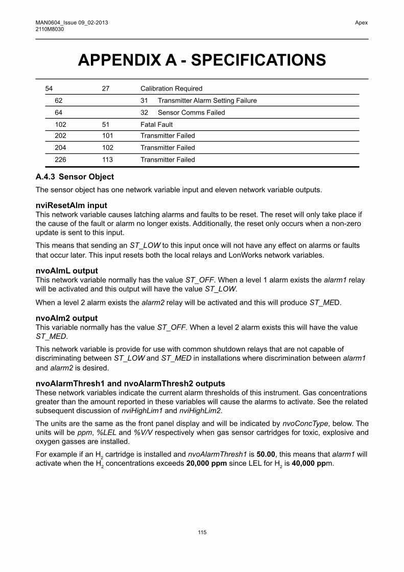
115
MAN0604_Issue 09_02-2013 Apex2110M8030
APPENDIX A - SPECIFICATIONS54 27 Calibration Required
62 31 Transmitter Alarm Setting Failure
64 32 Sensor Comms Failed
102 51 FatalFault 202 101 TransmitterFailed
204 102 TransmitterFailed
226 113 Transmitter Failed
A.4.3 Sensor ObjectThe sensor object has one network variable input and eleven network variable outputs.
nviResetAlm inputThis network variable causes latching alarms and faults to be reset. The reset will only take place if thecauseofthefaultoralarmnolongerexists.Additionally,theresetonlyoccurswhenanon-zeroupdate is sent to this input.
This means that sending an ST_LOW to this input once will not have any effect on alarms or faults that occur later. This input resets both the local relays and LonWorks network variables.
nvoAlmL outputThis network variable normally has the value ST_OFF. When a level 1 alarm exists the alarm1 relay will be activated and this output will have the value ST_LOW.
When a level 2 alarm exists the alarm2 relay will be activated and this will produce ST_MED.
nvoAlm2 outputThis variable normally has the value ST_OFF. When a level 2 alarm exists this will have the value ST_MED.
This network variable is provide for use with common shutdown relays that are not capable of discriminating between ST_LOW and ST_MED in installations where discrimination between alarm1 and alarm2 is desired.
nvoAlarmThresh1 and nvoAlarmThresh2 outputsThese network variables indicate the current alarm thresholds of this instrument. Gas concentrations greater than the amount reported in these variables will cause the alarms to activate. See the related subsequent discussion of nviHighLim1 and nviHighLim2.
The units are the same as the front panel display and will be indicated by nvoConcType, below. The units will be ppm, %LEL and %V/V respectively when gas sensor cartridges for toxic, explosive and oxygen gasses are installed.
For example if an H2 cartridge is installed and nvoAlarmThresh1 is 50.00, this means that alarm1 will activate when the H2 concentrations exceeds 20,000 ppm since LEL for H2 is 40,000 ppm.

116
MAN0604_Issue 09_02-2013 Apex2110M8030
APPENDIX A - SPECIFICATIONSnvoCellLife outputThisvariablereportsthetotalcellliferemaining.Thisiscelltypespecific,butistypicallysetfornewcartridges at 2 years of service. It is reported in hours of life.
NvoNextCal outputThis variable reports when the next calibration is required. The default is 6 months of service between calibrations. It is reported in hours (interval starts at 4320hrs and counts to zero).
nvoLastCal outputThis variable indicates the time since last calibration, counting back from current time.
nvoCellType outputThis string contains the name of the gas that the installed cartridge is capable of detecting. It is the same string that appears on the front panel of the transmitter. For example cO or hF. This has a 5 character maximum.
nvoConc outputThisisthegasconcentrationasafloatingpointnumber.TheunitsarethesameasnvoAlarmThresh1, see above.
nvoConcFS outputThisfloatingpointnumberreportsthemaximumconcentrationthattheinstalledsensoriscapableofmeasuring. The units are the same as nvoAlarmThresh1, see above.
nvoConcType outputThis string contains the measurement units for the installed cartridge. Possible values include ppm, %V/V and %LEL.
A.4.4 Virtual Function BlockThefournetworkconfigurationinputsappearinavirtual functional block in Echelon LonMaker3.
nciMaxSendT inputThis controls the time period between updates of bound but unchanging network variable outputs. The default is 20 seconds but this can be changed from 1 to 59 seconds depending on installation-specificneeds.
nciAlarmSetT inputReporting of alarm events over LonWorks may be delayed by up to 59 seconds by setting this parameter to a non-zero value. However this has no effect on alarm reporting over the analog current loop or the local relays.
Thisisincludedtosuppressephemeralalarmeventswhichmaybecausedbyfluctuationsintemperature, pressure, or humidity or by strong radio-frequency interference. The default value of zero is recommended for most applications.
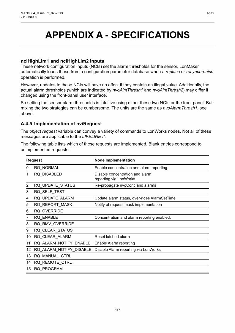
117
MAN0604_Issue 09_02-2013 Apex2110M8030
nciHighLim1 and nciHighLim2 inputsThesenetworkconfigurationinputs(NCIs)setthealarmthresholdsforthesensor.LonMakerautomaticallyloadsthesefromaconfigurationparameterdatabasewhenareplace or resynchronise operation is performed.
However, updates to these NCIs will have no effect if they contain an illegal value. Additionally, the actual alarm thresholds (which are indicated by nvoAlmThresh1 and nvoAlmThresh2) may differ if changed using the front-panel user interface.
So setting the sensor alarm thresholds is intuitive using either these two NCIs or the front panel. But mixing the two strategies can be cumbersome. The units are the same as nvoAlarmThresh1, see above.
A.4.5 Implementation of nviRequestThe object request variable can convey a variety of commands to LonWorks nodes. Not all of these messages are applicable to the LIFELINE II.
The following table lists which of these requests are implemented. Blank entries correspond to unimplemented requests.
Request Node Implementation
0 RQ_NORMAL Enableconcentrationandalarmreporting1 RQ_DISABLED Disableconcentrationandalarm reporting via LonWorks 2 RQ_UPDATE_STATUS Re-propagatenvoConcandalarms3 RQ_SELF_TEST 4 RQ_UPDATE_ALARM Updatealarmstatus,over-ridesAlarmSetTime5 RQ_REPORT_MASK Notifyofrequestmaskimplementation6 RQ_OVERRIDE 7 RQ_ENABLE Concentrationandalarmreportingenabled.8 RQ_RMV_OVERRIDE 9 RQ_CLEAR_STATUS 10 RQ_CLEAR_ALARM Resetlatchedalarm11 RQ_ALARM_NOTIFY_ENABLE EnableAlarmreporting12 RQ_ALARM_NOTIFY_DISABLE DisableAlarmreportingviaLonWorks13 RQ_MANUAL_CTRL 14 RQ_REMOTE_CTRL 15 RQ_PROGRAM
APPENDIX A - SPECIFICATIONS

118
MAN0604_Issue 09_02-2013 Apex2110M8030
APPENDIX A - SPECIFICATIONS
A.4.6 Interpretation of nvoStatusThe object status contains a great deal of information about the status of a node. Several bits have meaningassignedwhichisspecifictoHoneywellAnalytics.
For example fault_alert (Honeywell nomenclature) has been mapped to mechanical_fault (LonMark nomenclature).
The following table lists all of these assignments. Blank entries correspond to unimplemented status bits.
Status Field Node 0 interpretation
object_id(16bits) 0invalid_id object_id>1 invalid_request Unimplemented request made disabled Network reporting inhibited out_of_limits Warning alert active open_curcuit out_of_service Not in normal mode mechanical_fault Fault alert active feedback_failure over_range Concentration > full scale under_range electrical_fault unable_to_measure Sensor is not connected comm_failure Error inside LIFELINE II fail_self_test Error inside LIFELINE II self_test_in_progress locked_out Remote access unavailable manual_control in_alarm Alarm level 1 is active in_override report_mask nvoStatus mask report programming_mode programming_fail Request made could not be implemented alarm_notify_disable Alarm reporting over network is disabled.

119
MAN0604_Issue 09_02-2013 Apex2110M8030
APPENDIX B - CERTIFICATIONThisappendixdefinesthecertificationsfortheApexgassensingsystemcomponents.ItincludestheCSA and UL Control Drawings, see B.4.
B.1 TRAnSmiTTER UniTTheTransmitterUnitisdesignedandapprovedforuseinhazardousareas.
TherearethreecertifiedversionsoftheTransmitterUnit:
• ATEX Part No: 2110B2200 • UL Part No: 2110B2203 • CSA Part No: 2110B2204AcertificationlabelislocatedontopoftheAPEXTransmitterUnit.Thelabelcontainsalltherelevantinformationregardingtheproduct’sidentificationandcertificationstate.
ATEx
UlCLASS I, DIV 1, GROUPS B, C, D
OP.TEMPCODE T4(Tamb.-40to+80oC) T5(Tamb.-40to+55oC)
cSACLASS I, DIV 1, GROUPS B, C, DOP.TEMPCODE T4(Tamb.-40to+75oC) T5(Tamb.-40to+55oC)Note: TransmitterUnitcertifiedtoCSA 22.2 No. 152 onlywhencertifiedsensorisfittedwithspecific
cartridges.SeeB.5ControlDrawings,CSA(page126)
Identificationnumberof ATEXnotifiedbody
ATEXHazardousArea ApprovalCertificateNo.
ATEXMeasuring Function Approval CertificateNo.
CertificateCode
Serial Number/ Year of Manufacture
Warnings
ModificationStatus
Manufacturer’s Trademark & Address Product Name
Explosion Protection Mark and Equipment
CertifiedAmbient Temperature
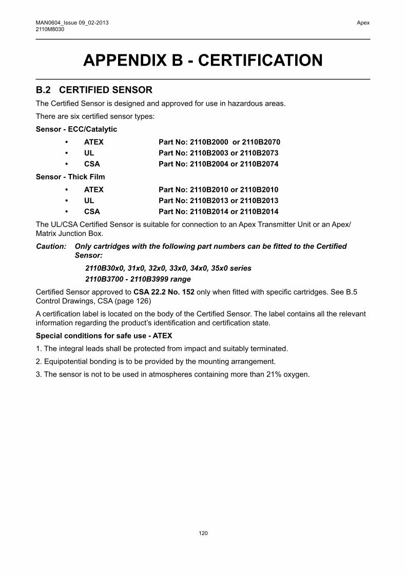
120
MAN0604_Issue 09_02-2013 Apex2110M8030
APPENDIX B - CERTIFICATIONB.2 cERTiFiEd SEnSORTheCertifiedSensorisdesignedandapprovedforuseinhazardousareas.
Therearesixcertifiedsensortypes:
Sensor - ECC/Catalytic • ATEX Part No: 2110B2000 or 2110B2070 • UL Part No: 2110B2003 or 2110B2073 • CSA Part No: 2110B2004 or 2110B2074Sensor - Thick Film
• ATEX Part No: 2110B2010 or 2110B2010 • UL Part No: 2110B2013 or 2110B2013 • CSA Part No: 2110B2014 or 2110B2014TheUL/CSACertifiedSensorissuitableforconnectiontoanApexTransmitterUnitoranApex/Matrix Junction Box.
Caution: OnlycartridgeswiththefollowingpartnumberscanbefittedtotheCertifiedSensor:
2110B30x0, 31x0, 32x0, 33x0, 34x0, 35x0 series 2110B3700 - 2110B3999 rangeCertifiedSensorapprovedtoCSA 22.2 No. 152onlywhenfittedwithspecificcartridges.SeeB.5Control Drawings, CSA (page 126)
AcertificationlabelislocatedonthebodyoftheCertifiedSensor.Thelabelcontainsalltherelevantinformationregardingtheproduct’sidentificationandcertificationstate.
Special conditions for safe use - ATEX1. The integral leads shall be protected from impact and suitably terminated.
2. Equipotential bonding is to be provided by the mounting arrangement.
3. The sensor is not to be used in atmospheres containing more than 21% oxygen.

121
MAN0604_Issue 09_02-2013 Apex2110M8030
ATEx
UlAPEX/MATRIXSENSOR:
CLASS I, DIV 1, GROUPS B, C, D
OP.TEMPCODE T4(Tamb.-40to+80oC) T5(Tamb.-40to+55oC)
APPENDIX B - CERTIFICATION
Identification number of ATEXnotified body
ATEXHazardous Area Approval CertificateNo.
Test House Trademark
Certificate Code
Serial Number/ Year of Manufacture
CE Mark - Conforms to all Applicable European Directives
Issue Status
Manufacturer’s Trademark & Address
Product Name
Explosion Protection Mark and Equipment Group and Catagory
Certified Ambient Temperature Range

122
MAN0604_Issue 09_02-2013 Apex2110M8030
APPENDIX B - CERTIFICATIONcSAAPEX/MATRIXSENSOR:
CLASS I, DIV 1, GROUPS B, C, DOP.TEMPCODE T4(Tamb.-40to+75oC) T5(Tamb.-40to+55oC)CertifiedSensorapprovedtoCSA 22.2 No. 152onlywhenfittedwithspecificcartridges.SeeB.5Control Drawings, CSA (page 126)
B.3 CERTIFIED JUNCTION BOXTheCertifiedJunctionBoxisdesignedandapprovedforuseinhazardousareas.
TherearetwotypesofCertifiedJunctionBox:
• ATEX Ex d Part No: 2110B2100 • UL/CSA Explosion Proof Part No: 2110B2103AcertificationlabelislocatedontopoftheCertifiedJunctionBox.Thelabelcontainsalltherelevantinformationregardingtheproduct’sidentificationandcertificationstate.
Identificationnumberof ATEXnotifiedbody
Test House Trademark
Certificate Code
Serial Number/ Year of Manufacture
CE Mark - Conforms to all Applicable European Directives
Issue Status
Manufacturer’s Trademark & Address
Product Name
Explosion Protection Mark and Equipment Group and Catagory
Certified Ambient Temperature Range
Warnings
Part number

123
MAN0604_Issue 09_02-2013 Apex2110M8030
APPENDIX B - CERTIFICATIONATExUlAPEX/MATRIXJUNCTIONBOX:
CLASS I, DIV 1, GROUPS B, C, D
OP.TEMPCODE T4(Tamb.-40to+80oC)
T5(Tamb.-40to+55oC)
cSACLASS I, DIV 1, GROUPS B, C, DOP.TEMPCODE T4(Tamb.-40to+75oC) T5(Tamb.-40to+55oC)
B.4 ACCESSORIESThe followingaccessoriesconform toCSAC22.2No.152whenfitted to theCertifiedSensorwithcartridge Part No: 2110B3754installed: • Collecting Cone Part No: 2110B2151 • Flow Housing Part No: 2110B2140 • Weather Housing Part No: 2110B2150
• Sunshade Part No: 2110B2152

124
MAN0604_Issue 09_02-2013 Apex2110M8030
APPENDIX B - CERTIFICATIONB.5 CONTROL DRAWINGS
Ul

125
MAN0604_Issue 09_02-2013 Apex2110M8030
APPENDIX B - CERTIFICATIONcSA
HAZ
ARD
OU
S(C
LASS
IFIE
D)
LOC
ATIO
NC
LASS
,DIV
.1G
RO
UPS
B,C
,DC
22.2
No.
152
I
SWIT
CH
EDO
UTP
UTS
ENTR
YST
OPP
ING
PLU
GFA
CTO
RY
FITT
ED
.ON
LYR
EMO
VEIF
REL
AYC
ON
NE
CTI
ON
SR
EQU
IRED
.(C
SA
LIS
TED
CO
ND
UIT
SE
AL
RE
QU
IRE
D W
ITH
IN 1
8”)
VM
AX
28V
dc
IMA
X 1
AR
ES
ISTI
VE
LO
AD
ON
LY
NO
N-H
AZAR
DO
US
CO
NTR
OL
EQU
IPM
ENT
NO
TE1
SEN
SOR
ENTR
YN
OTE
2
TRAN
SMIT
TER
UN
ITTY
PE:A
PEX
JUN
CTI
ON
BOX
TYPE
:AP
EX/M
ATR
IX
SEN
SOR
TYPE
:AP
EX/M
ATR
IXSE
NSO
R
NO
TES:
1.AP
PAR
ATU
SW
HIC
HIS
UN
SPEC
IFIE
DEX
CEP
TTH
ATIT
MU
STN
OT
BES
UPP
LIED
FRO
M,N
OR
CO
NTA
ININ
NO
RM
ALO
RAB
NO
RM
ALC
ON
DIT
ION
SA
SOU
RC
EO
FPO
TEN
TIAL
WIT
HR
ESPE
CT
TOEA
RTH
INEX
CE
SSO
F25
0vrm
sO
R25
0Vd.
c.
2.SE
NSO
R(T
YPE:
APE
X/M
ATR
IXSE
NSO
R)C
ANB
ED
IREC
TLY
CO
NN
ECTE
DTO
THE
TRAN
SMIT
TER
UN
IT(T
YPE:
APE
X)
3.FO
RIN
STA
LLAT
ION
NO
TR
EQU
IRIN
GAN
APE
XTR
ANSM
ITTE
R,T
HE
APEX
/MAT
RIX
SEN
SOR
AND
JUN
CTI
ON
BO
XM
AYBE
DIR
ECTL
YC
ON
NEC
TED
TOTH
EC
ON
TRO
LE
QU
IPM
ENT
INTH
EN
ON
HAZ
ARD
OU
SAR
EA.
4.SE
NSO
RC
ARTR
IDG
ESAR
ESU
PPLI
EDFR
OM
INTR
INSI
CAL
LYSA
FEC
IRC
UIT
SW
ITH
INTH
ESE
NSO
RB
OD
Y.C
ARTR
IDG
ESM
AYTH
EREF
OR
EBE
REP
LAC
EDIN
THE
HA
ZAR
DO
US
LOC
ATIO
N,W
ITH
OU
TN
ECE
SSIT
YO
FP
OW
ERIN
GD
OW
NTH
EAP
EXSY
STEM
.FIT
ON
LYC
ART
RID
GES
PAR
T N
os. 2
110B
3XXX
- SE
E M
ANU
AL.
SEN
SOR
EN
TRY
(CSA
LIS
TED
C
ON
DU
IT S
EAL
REQ
UIR
ED W
ITH
IN 1
8”)
SEN
SO
RC
ARTR
IDG
ESE
EN
OTE
4
ALTE
RN
ATIV
ER
OU
TIN
GSE
EN
OTE
3JU
NC
TIO
N B
OX
ENTR
Y (C
SALI
STED
CO
ND
UIT
SEA
L R
EQU
IRE
WIT
HIN
18”
)
OR
AN
Y S
UIT
AB
LY
AP
PR
OV
ED
CS
A
JUN
CTI
ON
BO
X
DIS
PLA
Y/K
EY
PA
DS
EE
NO
TE 5
SUPP
LY E
NTR
Y (C
SA L
ISTE
D
CO
ND
UIT
SEA
LR
EQU
IRED
WIT
HIN
18”
)
5. T
RAN
SMIT
TER
PR
OVI
DES
I.S.
CIR
CU
ITS
FOR
DIS
PLAY
/KEY
PAD
.
CO
MB
US
TIB
LE C
AR
TRID
GE
SC
OM
PLI
AN
T W
ITH
C22
.2 N
o. 1
52
Gas
R
ange
P
art N
o.1*
10
0%LE
L 21
10B
3930
2*
100%
LEL
2110
B39
313*
10
0%LE
L 21
10B
3932
4*
100%
LEL
2110
B39
335*
10
0%LE
L 21
10B
3934
6*
100%
LEL
2110
B39
357*
10
0%LE
L 21
10B
3936
8*
100%
LEL
2110
B39
37B
utan
e 10
0%LE
L 21
10B
3752
Eth
ylen
e 10
0%LE
L 21
10B
3758
Hyd
roge
n 10
0%LE
L 21
10B
3757
Met
hane
10
0%LE
L 21
10B
3754
Pro
pane
10
0%LE
L 21
10B
3751

126
MAN0604_Issue 09_02-2013 Apex2110M8030
APPENDIX C - ACCESSORIES & SPARE PARTSThis appendix lists the accessories and spare parts available for the Apex system.
c.1 AccESSORiESDescription Part Number
CertifiedJunctionBoxforremoteCertifiedSensormounting:ATEXExd 2110B2100 UL/CSA 2110B2103CollectingCone 2110B2151FlowHousing 2110B2140Sunshade 2110B2152WeatherProtection 2110B2150
c.2 digiTAl cOmmUnicATiOnS BOARdDescription Part Number
LonWorksdigitalcommunicationsboard 2110B2600
c.3 SpARESDescription Part Number
Carbonfilter 2110B2172Hydrophobicfilter 2110B2171Meshfilter 2110B2170Sensorcap 2110B2800TransmitterUnitFrontPanelAssembly 2110B2820CSATransmitterUnitFrontPanelAssembly 2110B2825TransmitterUnitScrewandGasketSet 2110B2829
Note:Thefilterandsensorcapsparesincludetherequiredrubberseal.

127
MAN0604_Issue 09_02-2013 Apex2110M8030
APPENDIX D - GLOSSARYCartridge A replaceable assembly containing a gas transducer and associated calibration information.
Catalytic Bead Used for the detection of combustible gases. These are made of an electrically heated platinum wire coil,coveredfirstwithaceramicbaseandthenwithafinaloutercoatingofcatalyst.
cE mark Indicates compliance to all relevant European directives.
Electrochemical Sensor A gas sensitive electrode, formed by a permeable membrane and special electrolyte.
Gas Transducer An element that translates gas concentration into an electrically measurable quantity, such as electrochemicalcells,catalyticbeadsandthickfilmdevices.
lcd Liquid Crystal Display.
lEl Lower Explosive Limit is the lowest concentration of fuel in air which will burn and for most flammablegasesandvapoursitislessthan5%byvolume.
Note:forsomegases(e.g.methane)theLELlevelhasdifferentvaluesintheEuropeanandNorthAmerican standards.
lEl% PercentageoftheLowerExplosiveLimit(forexample,10%LELofmethaneisapproximately0.5%by volume).
lOn Local Operating Network.
pcB Printed circuit board.
peak Maximum, or minimum, measurement since switch on.
ppB Parts per billion concentrations in the atmosphere.
ppm Parts per million concentrations in the atmosphere.
rh Relative humidity.

128
MAN0604_Issue 09_02-2013 Apex2110M8030
Sensor Agastransducerwithinaprotectiveenclosure:sensorsmaybesafeorhazardousareamounted,and may also include some driving, interfacing, biasing or signal conditioning circuitry.
Transmitter Afielddevicethatislocallyconnectedtoagassensingtransducerthattranslatestherawsensoroutputintoauserusefulform,e.g.adisplay,4-20mAordigitaloutput.
UEl Upper Explosive Limit.
%vOl Concentration of explosive gas, measured in percentage by volume.
%V/V Another way of representing %VOL
APPENDIX D - GLOSSARY

Issue 9 02/2013
H_MAN0604_EMEAI
2110M8030 ECO A03956
© 2013 Honeywell Analytics 1106
0
Please Note:While every effort has been made to ensure accuracy in this publication, no responsibility can be accepted for errors or omissions. Data may change, as well as legislation, and you are strongly advised to obtain copies of the most recently issued regulations, standards, and guidelines. This publication is not intended to form the basis of a contract.
Contact Honeywell Analytics:
Find out more
www.honeywellanalytics.com
Europe, Middle East, Africa, IndiaLife Safety Distribution AGJavastrasse 28604 HegnauSwitzerlandTel: +41 (0)44 943 4300Fax: +41 (0)44 943 4398India Tel: +91 124 [email protected]
AmericasHoneywell Analytics Inc. 405 Barclay Blvd.Lincolnshire, IL 60069USATel: +1 847 955 8200 Toll free: +1 800 538 0363 Fax: +1 847 955 [email protected]
www.honeywell.com
Technical ServicesEMEAI: [email protected]: [email protected]: [email protected]
Asia Pacific Honeywell Analytics Asia Pacific #508, Kolon Science Valley (I) 187-10 Guro-Dong, Guro-Gu Seoul, 152-050 Korea Tel: +82 (0)2 6909 0300Fax: +82 (0)2 2025 [email protected]