TECHNICAL HANDBOOK - Centrale termice, climatizare, aer ... Quasar - Manual instalare.pdf ·...
31
TECHNICAL HANDBOOK INSTALLATION USE MAINTAINANCE Single phase Models 021 - 026 - 031 Three-phase Model 041 m.a.Ch. m.a.Ch.
Transcript of TECHNICAL HANDBOOK - Centrale termice, climatizare, aer ... Quasar - Manual instalare.pdf ·...

TECHNICAL HANDBOOKINSTALLATION
USE
MAINTAINANCE
Single phase Models 021 - 026 - 031
Three-phase Model 041
m.a.Ch.
m.a.Ch.

CONTENTS
TONON FORTY ENGLISH
1.0 GENERAL INFORMATION p. 11.1 FEATURES OF THE MAIN ELEMENT p. 11.2 MAIN FUNCTIONS OF THE CONTROLLER p. 11.3 ACCESSORIES AVAILABLE ON REQUEST p. 2
2.0 INSTALLATION p. 22.1 GENERAL INFORMATION p. 22.2 INSPECTION, HANDLING AND POSITIONING p. 22.3 TECHNICAL FEATURES p. 22.4 POSITIONING p. 3
3.0 HYDRAULIC CONNECTIONS p. 33.1 POSITIONING AND SERVICE AREAS p. 33.2 USE OF ANTI-FREEZE LIQUIDS p. 3
4.0 ELECTRIC CONNECTIONS p. 44.1 GENERAL INDICATIONS p. 44.2 ELECTRIC CONNECTIONS p. 4
5.0 USE OF THE MICROPROCESSOR CONTROLLER p. 55.1 USER INTERFACE p. 55.2 FUNCTIONS OF THE KEYS p. 65.3 COMBINED KEY FUNCTIONS p. 6
6.0 VISUALIZATION p. 66.1 DISPLAY DURING ALARMS p. 76.2 QUICK DISPLAY OF MAIN INFORMATION p. 76.3 UNIT IN STAND-BY p. 76.4 ACTIVATING / DISACTIVATING CHILLER MODE (SUMMER MODE) p. 76.5 ACTIVATING / DISACTIVATING HEATING MODE (WINTER MODE) p. 76.6 ACTIVATION / DISACTIVATION FROM DIGITAL INPUT p. 76.7 CONTROLLING THE CHILLER / HEAT PUMP WORKING
MODE FROM DIGITAL INPUT p. 8
7.0 ADJUSTING THE “SET POINT” p. 87.1 SEt.C Set point Chiller 12,5°C p. 87.2 SEt.H Set point Heat pump 38,5°C p. 87.3 SEt.D Dynamic Set point (Optional on request) p. 87.4 SEt.S Energy saving (Optional su richiesta) p. 97.5 AUTOMATIC CHANGE-OVER (OPTIONAL ON REQUEST) p. 9
8.0 BASE REMOTE CONTROL PANEL BASE KRC BASE (Optional on request) p. 108.1 ELECTRIC CONNECTIONS FOR THE BASE REMOTE CONTROL PANEL KRC BASE p. 108.2 TOP REMOTE CONTROL PANEL KRC TOP (Optional on request) p. 108.3 ELECTRICAL CONNECTIONS KRC Top p. 11
9.0 “M KEY” FUNCTION MENU p. 119.1 ACCESS TO THE “M” FUNCTION MENU p. 119.2 EXIT FROM THE FUNCTION MENU p. 119.3 DISPLAYING ALARMS p. 129.4 RESETTING AN ALARM p. 129.5 HOW TO DISPLAY THE ALARM HISTORY p. 129.6 ALARM CODES AND FUNCTIONS p. 139.7 OUTPUT BLOCK TABLE p. 159.8 DISPLAYING LOAD WORKING HOURS p. 159.9 RESETTING LOAD WORKING HOURS p. 15

TONON FORTY ENGLISH
10.0 PROGRAMMING FROM THE KEYBOARD p. 16
10.1 ACCESS TO “PR1” PARAMETERS (USER-LEVEL) p. 16
10.2 TO CHANGE PARAMETER VALUES p. 16
10.3 KEY SEQUENCE TO CHANGE PARAMETERS p. 16
11.0 COMPRESSOR ADJUSTMENT IN CHILLER OR HEAT PUMP MODE p. 17
11.1 OPERATING MODE OF THE CIRCULATION PUMP p. 17
11.2 TIMING p. 17
11.3 FAN FUNCTIONS p. 17
11.4 DCP PRESSURE CONTROL DEVICE p. 17
11.5 DEFROSTING p. 18
11.6 MANUAL DEFROSTING p. 18
11.7 DISPLAYING TIME LEFT TOCOMPLETE DEFROSTING p. 18
12.0 STARTING p. 19
12.1 PRELIMINARY CHECK p. 19
12.2 START UP p. 19
12.3 SUMMER MODE START UP p. 19
12.4 WINTER MODE START UP p. 19
12.5 INTERFACE WITH THE USER’S SYSTEM p. 20
12.6 OPERATING CHECKS p. 20
12.7 CHECKS p. 20
13.0 CONTROL AND SAFETY DEVICES p. 21
13.1 GENERAL INFORMATION p. 21
13.2 PERIODICAL PERIODIC MAINTENANCE AND CHECKS p. 21
13.3 STOPPING FOR THE SEASON p. 22
13.4 SAFETY INFORMATION p. 22
13.5 DEMOLISHING THE MACHINE AND DISPOSAL
OF TOXIC SUBSTANCES p. 22
14.0 FAILURE SOLVER p. 23
15.0 GENERAL HYDRAULIC DIAGRAM p. 25
16.0 COOLING CIRCUIT DIAGRAM p. 25
17.0 ELECTRIC DIAGRAM MODELS Quasar/Pulsar 021-026-031 p. 26
18.0 ELECTRIC DIAGRAM MODELS Quasar/Pulsar 041 p. 27
SPARE PARTS LIST p. 28

TONONFORTY S.p.A. ENGLISH
1
1.0 GENERAL INFORMATION
CHILLERS - Quasar
HEAT PUMPS - Pulsar
The Quasar and Pulsar units are both available in 4 models,
three single-phase and one threephase.
All the units are fitted with a single sealed Scroll compressor,
and are dimensioned for using R22 refrigerant or, on request,
R407C.
These units are ideal for either home use or for business
premises, with special attention paid to overall size and noise
emissions, offering a series of accessories to make installation
and maintenance easier.
All the units are supplied complete with wiring and ready for
connection to the customer's supply network. Before delivery,
each machine is tested when running, checking that all the safety
devices work correctly.
The range is divided between coolers (just cooled water) and
heat pumps (cooled or heated water).
Available models:
Quasar: Water coolers complete with pump and inertial
storage.
Pulsar: Heat pump complete with pump and inertial
storage.
All the units have the following hydraulic devices:
- water circulation pump
- compact system interface module
- water circulation safety flow-limit switch
- expansion tank (except for QUASAR models)
- 3-bar safety valve
Both the versions are supplied completely wired and fitted in a
panelled single block.
1.1 FEATURES OF THE MAIN ELEMENT
- Compressor sealed Scroll, primary brand, especially suitable
for home air conditioning, able to guarantee high efficiency
levels and very low noise and vibration emissions.
- Condensing coil with copper pipes mechanically expanded
into aluminium fins and galvanised steel heat-exchanger
supporting frame. On request, the fins can be supplied in copper
o r p r e - p a i n t e d a l u m i n i u m f o r
i n s t a l l a t i o n i n v e r y a g g r e s s i v e
atmospheres.
- Compact system interface module
with brazed plate evaporator in Aisi
316 stainless steel, immersed in the
storage tank. The module is made by a
welding process, controlled in each
phase, and tested on both the cooling
and the water s ide. This module
improves heat exchange efficiency, by
reducing heat dispersion.
- Fan section, with axial fan with
rotating stator blades, each fan has a
protection grid for accident prevention
in painted galvanised steel.
Modello A B C D E F Ø1 Ø2
021 / 026 1112 428 604,5 102,5 448 110 ¾” ¾”
031 / 041 1112 428 1113 102,5 448 110 ¾” ¾”
IN
OUT
Ø2
Ø1
B A
F
D
EC
m.a.Ch.m.a.Ch.
- Refrigeration circuit completely wired with copper pipe
fittings, including:
°Quasar dehydration filter, thermostatic valve with external
equalisation, safety pressure switches on the high and low
pressure sides, pressure tubes for filling and empty-ing the
refrigerant and connection for control pressure gauges. The
low-pressure side is isolated by thick foam anti-condensation
padding.
°Pulsar dehydrator filter, thermostatic valve with external
equalisation, cooling cycle inversion solenoid, check valve,
liquid receiver, safety pressure switches on the low and high
pressure side, pressure tubes for filling and emptying the
refrigerant and connection to the control pressure gauges.
The entire circuit is isolated by thick foam padding.
- Electric control panel, completely wired inside a sealed
steel box, made in conformity with the strictest European
standards. The power circuit is set for 230/1/50 or 400/3/50
V/ph/Hz supply, depending on the model, and includes the
hour me te r and magne to the rmal p ro tec t ion fo r the
compressor.
Microprocessor regulation and controls coupled to the safety
devices on board the unit or connected externally.
The working parameters are programmed and set directly on
the display module in the electric control panel, which is
accessible from the outside through the inspection flap on the
front panel of the unit.
1.2 MAIN FUNCTIONS OF THE CONTROLLER
Controls compressor start depending on the return water
temperature (temperature usually shown on the display).
Signal of triggered alarms on the display.
ON/OFF control of the circulation pump.
Direct control of fan speed by the air exchanger temperature
probe. Timing count for compressor and pump working.
WORKING LIMITSCooling cycle:Outside air temperature B.S. 10°C÷42°C
Cooled water temperature 4°C÷ 15°C
Heating cycle:Outside air temperature B.S. -10°C÷20°C
Hot water temperature 35°C÷ 50°C

TONON FORTY ENGLISH
2
HANDLING
We advise handling the unit inside i ts original
packing, which should only be removed when it is in
the final installation position.
It can be handled on a normal transpallet or by lifting,
using suspended cables that are sufficiently long to avoid
the top of the packing being crushed.
- Storage of programming data as protection in the case of
power failure.
- Storage of alarm list up to 50
- compressor activity control according to external temperature
(dynamic set-point)
- defrost function jointly controlled by temperature / pressure
1.3 ACCESSORIES AVAILABLE ON REQUEST
* MHL: high pressure and low pressure
* RAE: Evaporator anti-freeze heating element
* SAB: Supporting vibration reducer feet
* KRC Base: remote control kit with on-off, summer/winter
controls and alarm cut in.
* KRC Top - complete remote control kit
* DCP: Pressure control device
* V-Kit-Top: adapter for remote touch pad
* KRI: kit of additional heating element
* KRS485: TTl/rs485 output, serial communication protocol
ModBus
* All these accessories are supplied separately for install-
ation on site.
2.0 INSTALLATION
2.1 GENERAL INFORMATION
All installation and maintenance work must be performed by
qualified personnel, following the indications given in this
handbook and on board the unit. If these standards are not
applied, hazardous situations could arise for people, animals
and proper ty , for which the manufacturer accepts no
responsibility. The unit must be turned off at the mains by
turning off the automatic switch that is fitted near the unit,
before beginning any maintenance work on the unit. All the
units are manufactured for installation on the outside, and no
special protection is required against atmospheric agents.
2.2 INSPECTION, HANDLING AND POSITIONING
INSPECTION
Once the unit reaches its final destination, it must be carefully
checked visibly for any signs of damage that occurred during
transport.
The haulier must be immediately informed of any imperfections
or obvious signs of damage, and they must be noted on the
shipping note, TONON S.p.A. or your local agent must be
informed in writing as soon as possible.
2.3 TECHNICAL FEATURES

TONON FORTY ENGLISH
3
2.4 POSITIONING
The position for the unit must be clearly
defined, taking into account the following
precautions:
- The refrigerator must be installed on the
outside, on any flat horizontal surface, that
can support its weight (ground, terrace,
roof, etc.)
- If it is installed on the roof or a terrace,
rubber padding should be placed between
the unit and the surface, or special anti-
v i b r a t i o n s u p p o r t s ( a v a i l a b l e a s
accessories) to prevent any vibrations
being transmitted to the building structure.
- Install away from windows or openings
that communicate with the adjacent
buildings.
- Avoid installation near chimneys, flues, fans or air extractors,
to avoid the unit being exposed to hot or polluted air flows.
- All the models in the Quasar - Pulsar series have the fan section
fitted with horizontal air outlet.
- It is important that there are no obstacles to the airflow, which
could cause the air to recirculate between the suction and
delivery circuits.
- Insufficient air circulation or recirculation through the fin
condenser means the unit does not work properly and could
block it completely.
3.0 HYDRAULIC CONNECTIONS
PIPING
The piping can be in steel, galvanised steel, polyethylene or
PVC. All the units have threaded hydraulic attachments.
The units are supplied complete with circulating unit, to
guarantee an effective head as given in the enclosed table.
The pipes must be dimensioned on the basis of the pump output,
taking into account the pressure drop in the system.
All the piping must be correctly insulated to avoid heat storage
(cause a fall in system performance) and the formation of
condensation on the outside surface. Use 10-mm thick foam
insulating material. To avoid vibration transmission from the
unit to the main system, and to compensate heat expansion,
elastic joints should be fitted to the hydraulic attachments on the
unit.
The installation must be prepared in conformity with local
Standards or those of the Country of Installation.
3.1 POSITIONING AND SERVICE AREASThe unit must be positioned respecting the recommended service
spaces. This way the unit will work correctly, and all the parts are
easy to reach for maintenance purposes.
In any case, we recommend installing the following devices to
guarantee correct use and maintenance:
- Elastic anti-vibration joints
- Cut off valves
- Housing for the water temperature probes.
- Wiring net filter
- Air bleeding device
- Automatic filling unit
- Discharge valve
- Expansion tank (in the Pulsar models this is supplied as
standard).
For correct working and performance to be guaranteed, each unit
needs a constant nominal water capacity, as given in table 1 on
page 2.
If there is a lower water capacity, the unit could have working
problems with serious consequences and damage to some of the
main components, such as the compressor.
3.2 USE OF ANTI-FREEZE LIQUIDS
If water is not emptied from the hydraulic circuit during winter
months, an anti-freeze must be added to the water in the correct
percentage parts.
The use of anti-freeze liquids (table 2) reduces the cooling capacity
slightly, but gives a considerable variation in the water capacity
levels and pressure drop in the system.
In these cases, it is important to check the pump performance
carefully, to avoid any working problems or any damage that
could be caused if there is not the required water capacity.
IMPORTANT: the current pumps can work with a maximum
rate of glycol of 30%. To use the equipment with a higher mix,
please contact TONON FORTY S.p.a..
200500
200
1000
13 13 1087
2020
385
Compressor
External heat exchanger
Ventilator
Compact module for equipment interface
Pump
Electric panel

TONON FORTY ENGLISH
4
DEPENDING ON THE MODELS AND THE USER’S PLANT
LAYOUT, THE MACHINES MUST BE FITTED WITH A
SERIES OF COMPONENTS, THAT HAVE ALREADY BEEN
LISTED, TO GUARANTEE THE BESTOPERATIONS FROM
THE SYSTEM.
H O W E V E R , T H E S E C O M P O N E N T S M U S T B E
PERIODICALLY CHECKED TO ENSURE THEY ARE STILL
OPERATING CORRECTLY.
*PERIODICALLY CHECK THE SAFETY FLOW SWITCH
TRIGGERS.
*CHECK THE READING ON THE ANTIFREEZE PROBE, AND
COMPARE IT WITH A CERTIFIED INSTRUMENT. IF THE
READING IS INCORRECT, THEN THE PROBE MUST BE
GAUGED.
*PERIODICALLY CLEAN THE MESH FILTER AT THE
ENTRANCE TO THE MACHINE HEATEXCHANGER.
*CHECK THE PRESSURE IN THE HYDRAULIC PLANT IS
WITH IN THE SAFETY LIMITS (MAX 3 bar). IN NORMAL
CONDITIONS, THE HYDRAULIC PRESSURE CAN VARY
BETWEEN 0.8 ÷ 1.2 bar. DIFFERENCE IN LEVEL BETWEEN
THE CHILLING UNIT AND THE HIGHEST POINT IN THE
SYSTEM.
4.0 ELECTRIC CONNECTIONS
4.1 GENERAL INDICATIONS
All the units in the Quasar - Pulsar series are supplied with an
electric control panel with all the elements required for running
the unit and controlling the fitted safety devices.
Electric connections must be performed in conformity with
current CEI national standards or those relative to the country
where it is installed, following the indications given in the
enclosed wiring diagrams. Ensure the unit is turned off before
beginning any work on the internal or external electric parts.
Dimension the power lead section on the basis of the total
maximum power intake. The Technical Data table in this
manual shows the recommended sections for installation, when
a thermomagnetic - differential automatic switch is fitted near
the unit (table 1). Ensure there is adequate earth connection as
required by law, using the corresponding terminal inside the
electric control panel.
The power voltage must conform to the data of the unit
(voltage/frequency/ number of phases/neutral conductor); no
variations can be accepted +-5%, with unbalance between the
phases (for three-phase supply) less than 2%.
The use of incorrect power supply as requested by the
manufacturer, can compromise working and integrity of the
machine and the guarantee will be cancelled.
All the data for dimensioning the power circuit and the choice of electric protections (lead section and power intake) are given in table 1 on page 2.
4.2 ELECTRIC CONNECTIONSThe electric connections to be made by the user are reported in
the electric diagram and are summed up as follows:
• Connections to the mains supply
Number on terminal block in the electric panelModels 021 026 031 L-N-PE
Models 041 L1-L2-L3-N-PE
All the units are dimensioned to be sullpied with a neutral lead
for auxiliary circuits.
• On/Off remote control :blocks in the electric panel 4-5
USE A CLEAN CONTACT THAT IS NOT LIVE
Parameter CF16=0Logic: - closed contact :
working disactivated
- open contact:
working activated
You may invert the working logic of the digital on/off input, by
changing parameter CF16 in the user's menu (see page 16, par.
10.3).
• Summer / Winter remote activation:
Blocks in electric board: 4-6
-Function active only in EPA heat pump models. It allows you to
control the section chiller / heat pump from a remote touch pad.
USE A CLEAN CONTACT THAT IS NOT LIVE
max 1
5 m
IMPORTANT: from keyboard you can switch the unit on / off only
from a disactivated input (priority from remote control).

TONON FORTY ENGLISH
5
Working logic:
With parameter CF13=1 (standard configuration) and remote contact "open", the equipments works as a heat pump. When the contact is closed, it works as a chiller.With parameter CF13=0 and remote contact "open", it forces the equipment to work as a chiller. When the contact is closed, it works as a heat pump.
• Alarm signal from remote position:
Blocks 4 - 7 (open collector output to control a 12V /40mA relay)
-Permette di riportare a distanza un segnale di“allarme intervenuto”. Blocks 4-7 are directly connected to an open collector output, that can control a 12VDC/40mA relay. The output switches from 0 to 12Vdc, as soon as an alarm managed by the microprocessor starts.
The ralay is optional
Before connecting the relay, please respect the following connections:
IMPORTANT: The output signal from connector 7 (-12Vdc) directly controls the red LED "Allarme" on the base remote control (KRC Base), when a KRC Base is supplied as an accessory.
CF13=0 CF13=1
Contact closedUnit as a heat pump
Contact openUnit as a Chiller
- - 4 5 6
Numbers on the terminal block in the electric board
- - 4 5 6
- 4 5 6 7
+
-
+ -
5.0 USE OF THE MICROPROCESSOR CONTROLLER
All the units mount a microprocessor controller by which you can set all the typical parameters regulating the working of the equipment.
5.1 USER INTERFACEThe instrument display is divided into three areas.Left Upper Area: Evaporator. It shows user system water IN / OUT temperature.IN - inlet water temperature (return from user system)OUT - outlet water temperature (delivery to user system) Left Lower Area: It shows condensation temperature / pressure or the active time (function activated on call as an accessory).Right Area: Signalling icons.
Display IconsThe display icons give you all information on the state of the unit.
Celsius degrees
the value shown on the display is a temperature value (in the user's menu as well)
Bar
the value shown on the display is a pressure value (in the user's menu as well)
Compressor
The icon shows the compressor state:Blinking: the compressor is needed. A temporization is in progressLit: the compressor is active
Unit in Stand-by
The stand-by mode is active every time the unit is turned off from a chiller or a heat pump state. It is signalled by the lit iconEven in stand-by mode you can:
1) Visualize the detected temperature2) Manage the alarm situation by visualizing and signalising them3) Activate the heating element as antifreeze safety.
General Alarm
it signals the presence of one or more alarms. In case of auto-resetting alarm, access the M key function menu and select the "AlrM" function.
High pressure alarm
it signals that an alarm has been triggered by the high pressure safety pressure switch. The safety device is connected to ID3 digital input (see the applicable wiring diagram).
MM SETSET
prgprg 11 22
.hC.
a .mm.a.Ch.
°C
bar
11
ZZZZZZ
HH
m.a.Ch.m.a.Ch.
To use the Summer/Winter remote activation you have to set parameter CF28 on, in the user's menu (CF28=1). Once this parameter is active, the selection priority is from remote control (see page 15).

Low Pressure Alarm
it signals that an alarm has been triggered by the low pressure
safety pressure switch. The safety device is connected to ID4
digital input. (see the applicable wiring diagram).
Antifreeze heating element
Indica lo stato delle resistenze elettriche antigelo.
Flow switch alarm
it signals that an alarm has been triggered by the safety water
flow switch. The safety device is connected to ID1 digital
input. (see the applicable wiring diagram).
Clock / Counter
Maintenance needed
The compressors or the plant pump need maintenance for
exceeding working hours
Menu
It signals that "Function Menu" has been accessed
5.2 FUNCTIONS OF THE KEYS
TONON FORTY ENGLISH
6
M SETSET
prgprg12.312.3 ˚C
1 2
36.5m.a.Ch.
m.a.Ch.
5.3 COMBINED KEY FUNCTIONS
SYMBOLS AND LEDS ON THE FRONT PANEL
6.0 VISUALIZATION VISUALIZATION IN NORMAL CONDITION
Under normal working conditions, the instrument displays:
Upper Display:
Evaporator water inlet/outlet temperature (EWA EPA EWE
EWR air/water units, EWH EPH water/water units).
Lower Display:
Condensation temperature/pressure or evaporator water anti-
freeze temperature (pdc water/water units), with their units of
measurements.
Active time (optional).
L
Flow !Flow !
MenuMenu
prgprg
prgprg
M SETSET
M SETSET
M SETSET
prgprg
M SETSET
prgprg
M SETSET
prgprg To access programming mode
To exit programming mode
Simbolo Led Funzione
On Unit ON in chiller mode
On
Blinking
Blinking
On Defrost active
Off
Clock setting
The M key allows to access function menu and
time set-up.
The SET key allows to display or change the
set point value. In programming mode, it
selects a parameter or confirms a value
Keeping this key pressed for 5 sec will start or
stop the unit in cooling (chiller) mode of
o p e r a t i o n . I t s e l e c t s w a t e r I N / O U T
t e m p e r a t u r e s o n t h e u p p e r d i s p l a y . I n
p r o g r a m m i n g m o d e , i t s c r o l l s t h r o u g h
parameters codes or increases their value.
Keeping this key pressed for 5 sec will start the
unit in heating (pdc) mode of operation.
It selects outside air temperature / defrost
display.
In programming mode, i t scrol ls through
parameters codes or increases their value.
Pressing and holding these keys for more
than 5 sec will start a manual defrost cycle
Unit ON in heat pump mode
During programming phase (it
blinks together with LED )
Defrost Start Delay Time
Defrost disabled or finished

TONON FORTY ENGLISH
7
6.1 DISPLAY DURING ALARMS
Varying from a normal condition (no alarm active), as soon as an
alarm condition is detected, the instrument alternately shows
blinking alarm code and respective icon, and temperature /
pressure on the lower display (example given in the fig.:
presence of alarm high pressure).
6 . 2 Q U I C K D I S P L A Y O F M A I N INFORMATION
In order to help user during the machine test-and-check phase, the procedure for displaying main information without accessing selection menu has been simplified.
•· Pressing the key UP will display in rotation system
delivery and return temperatures. This function helps to check
the actual evaporator inlet/outlet thermal head, which should
corresponds approximately to 5°C in normal working conditions.
• · Pressing the DOWN key will display in rotation
outside air temperatures (probe available as optional) / and
condensation or defrost temperatures (pdc unit).
6.3 UNIT IN STAND-BY
Stand-by mode is enabled any time the unit is turned off, either
in chiller or in p.d.c. mode of operation. When the unit is in
stand-by mode, the icon will light up.
Also in stand-by mode, the controller allows to:
1) Display the detected measuraments
2) Menage alarm events by displaying and signalling them.
3) Activate heating elements as evaporator anti-freeze safety
device depending on thermoregulator.
Only by switching the unit off you can change from chiller to heat pump.
6.4 ACTIVATING / DISACTIVATING CHILLER
MODE (SUMMER MODE)
By pressing 5 seconds UP key , the unit changes from stand-
by to chiller mode or viceversa. After the delay timing, if no
alarm is active, the compressor starts. During the start the
"STAND-BY" icone turns off, while the SUN icone
referring to "Chiller" mode blinks. In "Chiller" mode only the
related set-point (“StC” Set Chiller) can be changed; otherwise
you can visualize the dynamic set-point (“StD”) if it is active.
6.5 ACTIVATING / DISACTIVATING HEATING MODE (WINTER MODE)
By pressing 5 seconds DOWN key , the unit changes from
stand-by to heat pump mode or viceversa. After the delay timing,
if no alarm is active, the compressor starts. During the start the
"STAND-BY" icone turns off, while the “SNOW” icon
related to "heat pump" mode. In heat pump mode only the
related set-point (“StH” Set Heat pump) can be changed;
otherwise you can visualize the dynamic set-point (“StD”) if it is
active.
6.6 ACTIVATION / DISACTIVATION FROM DIGITAL INPUT
This function is used if the unit on/off is remote controlled (i.e.
by a timer, see par. 4.2, p. 4).
USE A CLEAN CONTACT THAT IS NOT LIVE
1) It takes the precedence to the keyboard
2) You can turn the unit on/off, only when the digital input is
disactivated
M SETSET
prgprg18.518.5 ˚C
A07m.a.Ch.
m.a.Ch.
M SETSET
prgprg18.518.5 ˚C
1
Outm.a.Ch.
m.a.Ch.
M SETSET
prgprg12.312.3 ˚C
1
Inm.a.Ch.
m.a.Ch.
M SETSET
prgprg-11.6-11.6 ˚C
1
dEFm.a.Ch.
m.a.Ch.
M SETSET
prgprg18.518.5 ˚C
36.5m.a.Ch.
m.a.Ch. Z ZZ
ZZ
Z
ZZ
Z
5 sec.
M SETSET
prgprg18.518.5 ˚C
36.5m.a.Ch.
m.a.Ch.
1
ZZ
Z
5 sec.
M SETSET
prgprg18.518.5 ˚C
36.5m.a.Ch.
m.a.Ch.
1

TONON FORTY ENGLISH
8
3. When the digital input is inactive, the controller goes back to
the mode prior to the activation. The upper part of the display
shows "OFF" and the LED of the decimals blinks.
IMPORTANT: you can invert the polarity of input "id5", so
when the signal is active the unit is on. The parameter controlling
this function is CF16=1, and it can be modified by the user (see
par. Access to user's menu)
6.7 CONTROLLING THE CHILLER / HEAT PUMP
WORKING MODE FROM DIGITAL INPUT
To use the summer / winter remote control you have to
activate parameter CF28, in the user's menu (CF28=1).
Once this parameter is active, the selection priority is from
remote control.
When CF28=1, if the unit is on in Chiller or Heat pump mode
and the working mode is changed, the controller turns all the
outputs (compressor, pump...) off, and it waits the fixed delay
time, signalled by the blinking LEDS of the Chiller or of the
Heat pump. The blinking state indicates the working state whe
the unit is turned on again, waiting for the protection time of the
compressors.
7.0 ADJUSTING THE “SET POINT”
7.1 SEt.C Set point Chiller 12,5°C
By pushing the SET key when the unit is in stand-by or chille
mode you can display the set value. To change the set value just
push key SET about 5 seconds; the displayed value starts
blinking. Use the UP or DOWN keys to modify the value within
the limits set up in factory.
ST05 10°C minimum Summer set ST06 18°C maximum Summer set
7.2 SEt.H Set point Heat pump 38,5°C
When the unit is in stand-by or in heat pump mode, press SET
key to visualize the set value. To change the value, just press
SET key about 5 seconds; the value then starts blinking. Use the
UP or DOWN keys to modify the value within the limits set up
in factory.
ST07 36°C minimum Winter set ST08 43°C maximum Winter set
7.3 SEt.D Dynamic Set point (Optional on request)It allows to change the working set point according to the
temperature detected by pb4 probe, supplied as an accessory.
This function increases the compressor output C.O.P., favoring
energy saving
When the dynamic set point is on, press SET key twice to
visualize on the lower part of the display “Set.D” (dynamic set),
and on the upper part the actual working value of the set.
The label SETd is on only if the dynamic set point is a activated.
The parameters controlling the dynamic setpoint of chiller and
heat pump are directly set in the user's menu, taking care of the
following relations:
• Working Logic SEt.D Summer (Chiller)
If pB4 > = Sd04 SEt.D = SEt.CIf pB4 < = Sd04 – Sd06 SEt.D = SEt.C + Sd02
Sd02 Summer dynamic set point max offset. It establishes the
maximum variation for the set-point in chiller mode.
Sd04Set external air temperature, dynamic set point in chiller
mode.
Sd06 Temperature difference between external air and
dynamic set-point in chiller mode.
M SETSET
prgprgOFFOFF
m.a.Ch.
m.a.Ch.
M SETSET
M SETSET
prgprg38.538.5 ˚C
SEtHm.a.Ch.
m.a.Ch.
5 sec.
1
M SETSET
prgprg43.043.0˚C
SEtHm.a.Ch.
m.a.Ch.
1
M SETSET
prgprg43.043.0˚C
SEtHm.a.Ch.
m.a.Ch.
1
M SETSET
prgprg12.512.5 ˚C
SEtCm.a.Ch.
m.a.Ch.
5 sec.
1
M SETSET
prgprg10.010.0˚C
SEtCm.a.Ch.
m.a.Ch.
M SETSET
prgprg10.010.0˚C
SEtCm.a.Ch.
m.a.Ch.
Sd04 – Sd06 Sd04
SEt.C + Sd02
SEt.C
pB4
The value blinks, use the cursor to
modify the value.
Press SET key to save the change
The value blinks, use the cursor to
modify the value.
Press SET key to save the change

TONON FORTY ENGLISH
9
• winter functioning logic (heat pump)
With pB4 > = Sd05 SEt.D = SEt.HWith pB4 < = Sd05 + Sd07 SEt.D = SEt.H + Sd03.
Sd03 Increase maximum dynamic set-point in heat pump
function. Establishes the maximum variation for the set-
point in heat pump mode
Sd05 Set external air temperature, dynamic set point in
heat-pump mode
Sd07 Dynamic se t poin t outs ide a i r tempera ture
differential in heat pump mode of operation.
7.4 SEt.S Energy saving (Optional su richiesta)Energy Saving funtion allows to run two different working set points in both chiller / p.d.c. modes of operation.
It could be programmed daily or weekly by time bands (version
with on-board time clock, on-request accessory), or run by
external contact. During an Energy Saving cycle, the set point is
increased by the value set in ES10 / ES12, so that the working
set point will become SET+ES10 in chiller mode of operation, or
SET+ES12 in heat pump mode of operation. The referring
differential for thermoregulation with active energy saving will
correspond to the value of S11 parameter in chiller mode of
operation, ES13 parameter in heat pump mode of operation.
• E.S. Daily ProgrammingOnly for models with on-board time clock. Optional on request) Set the energy saving parameter relating to the day to 1.
E.g.: ES03 = 1 (energy saving active on Monday, 24 hour a
day). Set parameters from ES04 to ES09 to 1 to enable energy
saving during all the other days of the week.
• E.S. Time Band Programming(Only for models with on-board time clock. Optional on request)Set the parameter ES01 (Energy Saving cycle start time), ES02
(Energy Saving cycle stop time).
E.g.: ES01 = 8.0 ES02 = 10.0 energy saving active 8÷10.0 all
days of the week.
E.g.: ES01 = 23.0 ES02 = 8.0 energy saving active from 11.00
P.M. to 8.00 A.M. of the following day, all days of the week.
IMPORTANT: The time band function will be prohibited if parameters ES01 / ES02 are set to the same time or to 0.• Running E.S. from External Contact The E.S. function can always be run directly from id5 external
contact( CONNECTORS 4-5). To enable this function, set the
parameter CF10=8.
This operation uses the same digital input normally used as a
remote on/off (see par.4.2 p. 4).
IMPORTANT: depending on parameter CF16 the working logic is inverted.
Closed contact Closed contact
Energy saving active Energy saving inactive
USE A CLEAN CONTACT THAT IS NOT LIVE
• Parametri Energy SavingES01 Energy saving start time
ES02 Energy saving stop time
ES03 Monday 0 = disabled 1= enabled
ES04 Tuesday 0 = disabled 1= enabled
ES05 Wednesday 0 = disabled 1= enabled
ES06 Thursday 0 = disabled 1= enabled
ES07 Friday 0 = disabled 1= enabled
ES08 Saturday 0 = disabled 1= enabled
ES09 Sunday 0 = disabled 1= enabled
ES10 Energy saving setting increase in chiller mode of operation
ES11 Energy saving differential in chiller mode of operation
ES12 Energy saving setting increase in heat pump mode of
operation
ES13 Energy saving differential in heat pump mode of operation
7.5 AUTOMATIC CHANGE-OVER (OPTIONAL ON REQUEST)It automatically changes the unit state of functioning (chiller / heat pump) according to programming and external climatic conditions. This function works only with heat pump EPA supplied with an
optional PB4 environmental temperature sensor.
Parameters governing the change over function:
CF29 It allows to set the change over set point, which is the
value of the PB4-detected temperature below which the
instrument will force a p.d.c. mode of operation.
CF30 It allows to set the change over differential, which is the
temperature differential depending on which the instrument will
force a chiller mode of operation.
In order to help user set up the change over set point, pressing
and releasing the DOWN key will display the temperature
of PB4 probe for 5sec on the upper display, while the lower
display will show the Et label.
For temperatures within the CF30 differential, change over via keypad is allowed.
Sd05 Sd05+ Sd07
SEt.H + Sd03
SEt.H
pB4
M SETSET
prgprg37.237.2 ˚C
SEtdm.a.Ch.
m.a.Ch.
1
Example
CF16=0 CF16=1
4 5 4 5
CF29
Chiller
P.d.C.
CF30 Pb4

TONON FORTY ENGLISH
10
8.0 BASE REMOTE CONTROL PANEL BASE KRC BASE (Optional on request)
This touch pad allows the on/off control of all the Quasar and Pulsar units. With reversible Pulsar heat pumps you can switch from chiller to heat pump and viceversa. Moreover, a red LED signals the state of an active alarm. After completing the electric wirings as described below, check that the jumper on the right hand of the electric block is closed (supply 12Vac). A wrong setting of the jumper may damage the remote control.
IMPORTANT: Please, change CF16 = 1 parameter, so that the activation logic respects that of the remote control. You can change the parameter in the "User's menu", see par. 10.3 p. 16.
CONTROLS1. ON/OFF key2. Summer / Winter keyVISUALIZATION3 Green Led On4 Green Led Summer5 Green Led Winter6 Red Led AlarmSIZE-120 x 70 x 28.7 mm
8.1 ELECTRIC CONNECTIONS FOR THE BASIC REMOTE CONTROL PANEL KRC BASE
The electric connections between the remote control panel and the electric control board on the unit must be made on site, using a 6-pole cable with a minimum section of 0.5 sq.mm. The maximum recommended length must no exceed 150 meters.The electric connections to the remote control panel are the following:
nom
moC
nO
mralA
m u S/n iW
c aV 42 /2 1
c aV 42 /2 1
4 5 6 7 8 9
8.2 TOP REMOTE CONTROL PANEL KRC TOP (Optional on request)
Supplied as an on-request accessory, this kit allows to display and run all control parameters displayed as from machine controller. The keypad size enables the device to be installed within the very common (3 modules) wall boxes used in civil elecrtical systems. The remote terminal must be mounted on the panel, or on a 72x56 mm hole, and fixed using screws.
On
AlarmOnOff
Rear view of the remotecontrol panel
Closed Jumper 12Vac power supply
nom
moC
nO
mralA
muS/niW
c aV 42/21
c aV 42 /21
12v/24v
11
setset menmenùù
m.a.Ch.m.a.Ch.
11
setset menmenùù
m.a.Ch.m.a.Ch.
58
72100
64
1024
70
55
83.5
40
Terminal block of remote control
KRC Base
Terminal block in electric board Quasar/Pulsar
4 5 6 7 8 9Terminal block in
electric board Quasar/Pulsar
24 Vac power supply
Alarm relay 24 Vac
8.1.1 CONNECTION TO AN EXTERNAL ALARM RELAY

TONON FORTY ENGLISH
11
To obtain a IP65 front protection, use the front protection
rubber, mod. RGW-V (optional). For external fixing on wall, a
V-KIT vertical keypad adapter, as the one shown in figure 2, is
available.
FUNZIONE DEI TASTI KRC Top
8.3 ELECTRICAL CONNECTIONS KRC Top
The electric connection between the unit switchboard and
the remote control panel has to be done on site using a 2
wire shielded cable 0,5 mmq size. The Max suggested length
is 80 m. With connections exceeding this length the wire
size has to be increased up to 1,5 mmq for a 150 m max
length.
Connection cables are NOT included in the KRC accessory
kit.
The M key allows to access function menu
and time set-up.
menmenù
setset
IMPORTANT: Respect polarity as shown in the scheme
below:
block in electric board 1 + block in krc 1+
block in electric board 2- block in krc 2-
If wrong connected, the remote display does not lightup.
The keyboard is still protected, and if wrongly connected, all
you have to do is invert polarity
9.0 “ M KEY ” FUNCTION MENU
Accessing the function menu will allow you to:
1) Display and reset triggered alarms
2) Display and reset controlled load working hours
3) Enable the control via infrared transmission (supplied as an
accessory)
4) Display alarm history
5) Delete alarm history
While the function menu is displayed, the “menu” icon is
lit up
9.1 ACCESS TO THE “M” FUNCTION MENU
Press and release the M (menu) key. The “menu” icon will
appear.
9.2 EXIT FROM THE FUNCTION MENU
Press and release the M key or wait for time-out (15s). The
“menu” icon will disappear.
M SETSET
prgprg37.237.2 ˚C
12.0m.a.Ch.
m.a.Ch.
1
figure 2
setsetmenmenù
m.a.Ch.m.a.Ch.
PVC box for outdoor
installation
Gasket for IP65
protection
Krc top remote
control panel
Covering flap
Terminal block in the
electric board 1 2 3 ............
+ -1 2
KRC Top
Rear view of
KRC Top
Max 80mt
The SET key allows to display or change the
set point value. In programming mode, it
selects a parameter or confirms a value.
This key allows to select water IN/OUT
tempreatures, on the upper display. In
programming mode, it scrolls through
parameter codes or increase their values.
This key allows to display outside air
defrost temperature. In programming
mode, it scrolls through parameter codes
or decrease their values.
Keeping this key pressed for 5 sec will start
or stop the unit in either chiller or heat pump
mode of operation.
Keeping this key pressed for 5 sec will start
or stop the unit in either chiller or heat pump
mode of operation

TONON FORTY ENGLISH
12
9.3 DISPLAYING ALARMS
The system runs about 30 alarm codes. The most important
are displayed by means of icons at the sides of the two
displays. All the alarms can be identified through a code,
and stored, up to 50, in time wise ordervengono visualizzati tramite icone laterali ai 2 display. Tutti gli allarmi sono identificabili tramite codice, e memorizzati fino ad un massimo di 50 in ordine temporale.
Access function menu:
1) By using the UP or DOWN KEYS select the
“ALrM” function.
2) Press and release the SET key.
3) By using the UP or DOWN keys scroll through all the
alarms. To exit, press the menu key or wait 15s for time-out.
9.4 RESETTING AN ALARM
In case of a serious alarm, such as high pressure,evaporator
antifreeze, etc., the system must be manually reset.
All the arisen alarm codes (manual and auto reset) are
recorded in the Eprom, to allow an alarm diagnosis even
long time later.
IMPORTANT: If the alarm continues, call the TONON
Authorized Service Centre.
Procedure to manually reset the alarms1) Access the Functions Menu
2) Select the “ALrM” function
3) By pressing SET the lower display will show the alarm code
4) Upper display: rSt lebel if the alarm is resettable, e l’allarme
e resettabile, label NO label if it is not resettable.
Scroll through all available alarms by using the keys.
5) Press SET next to the rSt label to reset the alarm and move
to the next one
6) To exit, press the menu key or wait for the 15seconds'
timeout.
9.5 HOW TO DISPLAY THE ALARM HISTORY
1) Access the function menu
2) By using the UP or DOWN keys select the ALOG function
3) Press SET: the lower dislay will show a label indicating an
alarm code, the upper display the “n°” label indicating a
progressive number
4) By using the the UP or DOWN keys scroll through
all the available alarms.
5) To exit ALOG funcion and revert to standard display, press
the M key or wait for time-out (15 sec) to expire. The
memory can store up to 50 alarms; any new detected alarm
exceeding that number will automatically delete the oldest
alarm from the memory (alarms are displayed from the
oldest to the most recent).
IMPORTANT: The alarm history can be deleted only through the maintenance password.
M SETSET
prgprg
ALrMm.a.Ch.
m.a.Ch.
1
M SETSET
prgprgrStrSt
A01m.a.Ch.
m.a.Ch.
H
M SETSET
prgprg
ALrMm.a.Ch.
m.a.Ch.
M SETSET
prgprg37.237.2 ˚C
10.5m.a.Ch.
m.a.Ch.
1
M SETSET
prgprg
ALoGm.a.Ch.
m.a.Ch.
1
M SETSET
prgprgn 01n 01
A01m.a.Ch.
m.a.Ch.
1
M SETSET
prgprgn 02n 02
A07m.a.Ch.
m.a.Ch.
1
M SETSET
prgprgPASPAS
ArStm.a.Ch.
m.a.Ch.
1
M SETSET
prgprg --- ---
PASm.a.Ch.
m.a.Ch.
1

Code Meaning Cause Action Reset
P1 Alarm PB1 probe
P2 Alarm PB2 probe
P3 Alarm PB3 probe
P4 Alarm PB4 probe
A01
A02
A05
A06
A07
A08
A09
A10
9.6 ALARM CODES AND FUNCTIONS
TONON FORTY ENGLISH
13
Faulty probe or resistive
value out of range
It activates the alarm relay output
It activates the buzzer
The general alarm icon blinks
Code on the display
It activates the alarm relay output
It activates the buzzer
The general alarm icon blinks
Code on the display
It activates the alarm relay output
It activates the buzzer
The general alarm icon blinks
Code on the display
It activates the alarm relay output
It activates the buzzer
The general alarm icon blinks
Code on the display
Alarm high
pressure switch
Alarm Low
pressure switch
Faulty probe or resistive
value out of range
Faulty probe or resistive /
current value out of range
Faulty probe or resistive
value out of range
The Hp1 high-pressure
gauge triggers
Open-collector / alarm relay activated
Buzzer activated
“High Pressure Alarm” icon blinking
Code displayed
Open-collector / alarm relay activated
Buzzer activated
“LowPressure Alarm” icon blinking
Code displayed
The Lp1 low-pressure
gauge triggers
High temperature
High pressure
AL11 limit exceeded by
PB3 probe (condensation
control)
Open-collector / alarm relay activated
Buzzer activated
“Alarm High Pressure” icon blinking
Code displayed
Low temperature
Low pressure
AL13 limit exceeded by
PB3 probe defrosting
control)
Open-collector / alarm relay activated
Buzzer activated
“Alarm Low Pressure” icon blinking
Code displayed
Alarm anti-freezing AR03 limit exceeded set
antifreeze alarm by pB2
probe on the evaporator
(delivery temperature)
Flow switch alarm
Open-collector / alarm relay activated
Buzzer activated
“Generic Alarm” icon blinking
Code displayed
Open-collector / alarm relay activated
Buzzer activated
“Flow switch Alarm” icon blinking
Code displayed
Open-collector / alarm relay activated
Buzzer activated
“Generic Alarm” icon blinking
Code displayed
Open-collector / alarm relay activated
Buzzer activated
“Generic Alarm” icon blinking
Code displayed
Alarm compressor
1, thermal relay
Alarm compressor
2, thermal relay
Safety device triggers on
the evaporator water
delivery (FL)
Digital input activated by
the magnetothermal
switch on compressor 1
Digital input activated by
the magnetothermal
switch on compressor 2
Automatic
if the value returns within the set range
Automatic
if the value returns within the set range
Automatic
if the value returns within the set range
Automatic
if the value returns within the set range
Manual
Return to the pressure range plus reset
procedure at point 9.4
Automatic, it becomes manual after 2 triggers
in one hour
Manual
Return to the pressure range plus reset
procedure at point 9.4
Manual
Return to the pressure range plus reset
procedure at point 9.4
Automatic, it becomes manual after 2 triggers
in one hour
Manual
Return to the pressure range plus reset
procedure at point 9.4
Manual
Return to the pressure range plus reset
procedure at point 9.4
Automatic, it becomes manual after 2 triggers
in one hour
Manual
Return to the pressure range plus reset
procedure at point 9.4
Reset the safety device plus reset procedure
at point 9.4.
Reset the safety device plus reset procedure
at point 9.4.

000 ALARM CODES AND FUNCTIONS
TONON FORTY ENGLISH
14
A11
.
A12
A13
A14
A15
rtC Alarm
Time Clock
Time Clock to be set
rtF
EE
ACF
1
ACF
2
ACF
3
ACF
4
AFr
Alarm Condensation fan
Digital input activated by
the fan thermal switch
(thermal and klixon)
End of defrosting for dF07
(maximum time)
Defrost alarm error
Alarm
Compressor 1
Maintenance
Alarm
Compressor 2
Maintenance
Alarm
Water pump
Maintenance
Alarm
Time Clock
Alarm
Eprom error
Alarm
Configuration
Alarm
Configuration
Alarm
Configuration
Alarm
Configuration
Alarm
Mains supply
frequency
Compressor 1 working
hours exceeded
Compressor 2 working
hours exceeded
Working hours > CO16
Time Clock fault
Clock malfunctioning
Memory data loss
Unit configured as heat
pump with non-configured
reversal valve
Air/air air/water units
without probe configured
for condensation control
Two digital inputs having
the same configuration
CF28= 1 and digital input
non-configured or
CF28=2 probe PB4 other
than 3
Mains supply frequency
out of range
Open-collector / alarm relay activated
Buzzer activated
“Alarm Generic” icon blinking
Code displayed
Code displayed
Only signalling
Open-collector / alarm relay activated
Buzzer activated
“Alarm Maintenance” icon blinking
Code displayed
Open-collector / alarm relay activated
Buzzer activated
“Alarm Maintenance” icon blinking
Code displayed
Open-collector / alarm relay activated
Buzzer activated
“Alarm Maintenance” icon blinking
Code displayed
Open-collector / alarm relay activated
Buzzer activated
“Generic Alarm” icon blinking
Code displayed
Open-collector / alarm relay activated
Buzzer activated
“Generic Alarm” icon blinking
Code displayed
Open-collector / alarm relay activated
Buzzer activated
“Generic Alarm” icon blinking
Code displayed
Open-collector / alarm relay activated
Buzzer activated
“Generic Alarm” icon blinking
Code displayed
Open-collector / alarm relay activated
Buzzer activated
“Generic Alarm” icon blinking
Code displayed
Open-collector / alarm relay activated
Buzzer activated
“Generic Alarm” icon blinking
Code displayed
Open-collector / alarm relay activated
Buzzer activated
“Generic Alarm” icon blinking
Code displayed
Open-collector / alarm relay activated
Buzzer activated
“Generic Alarm” icon blinking
Code displayed
Manual
Reset the safety device plus reset procedure at
point 9.4
Automatic
By a subsequent correct defrost
Manual
Manual
Working hour reset point 9.8
Manual
Working hour reset point 9.8
Manual
Working hour reset point 9.8
Manual
Clock setting plus reset procedure point 9.4
Manual
Reset procedure point 9.4
If after resetting the alarm re-occurs, change the
clock
Manual
Reset procedure point 9.4
If after resetting the alarm re-occurs, the
equipment will remain blocked
Automatic
By correct reprogramming
Automatic
By correct reprogramming
Automatic
By correct reprogramming
Automatic
By correct reprogramming
Automatic
When frequency returns within working
range

TONON FORTY ENGLISH
15
9.8 DISPLAYING LOAD WORKING HOURS
1) Access function menu
2) Press the keys until the lower display shows the
label of the single load; C1Hr (compressor 1 working hours),
CHr2 (compressor 2 working hours), PFHr (system water
pump working hours).
The upper display will show the working hours.
The icon is lit up.
9.7 OUTPUT BLOCK TABLE
Alarm Description Comp.1 Pump Boiler
P1Probe PB1 OFF
Yes
if Ar19 =0OFF OFF
P2Probe PB2 OFF
Yes
if Ar19 =0OFF OFF
P3Probe PB3 OFF
Yes
if Ar19 =0OFF OFF
P4Probe PB4 OFF
Yes
if Ar19 =0OFF OFF
A01 High pressure switch OFF
A02 Low pressure switch OFF OFF
A05 High temperature, high pressure OFF
A06 Low temperature, low pressure OFF OFF
A07 Antifreeze OFF OFF
A08 Flow switch OFF Boiler heater
OFF
OFF OFF
A09 Compressor 1 thermal relay OFF
--
A11 OFFOFF
A12 Defrost error
A13 Compressor 1 maintenance
--
A15 Water pump maintenance
rtC Time clock Alarm
RtF Time clock Alarm
EE Eprom error OFF OFF OFF OFF OFF
ACF1 Configuration Alarm OFF OFF OFF OFF OFF
ACF2 Configuration Alarm OFF OFF OFF OFF OFF
ACF3 Configuration Alarm OFF OFF OFF OFF OFF
ACF4 Configuration Alarm OFF OFF OFF OFF OFF
AFr Net frequency alarm OFF OFF OFF OFF OFF
M SETSET
prgprg 12 12
C1Hrm.a.Ch.
m.a.Ch.
1
9.9 RESETTING LOAD WORKING HOURS
1) Access function menu by pressing "M" key
2) Press the keys until the lower display shows the label
of the single load (C1Hr, C2Hr, PFHr) and the upper display
shows the working hours.
3) Keep the SET key pressed for 3 sec: the upper display will
show 0, which means the reset has been carried out
correctly.
4) Exit function menu by pressing the M key or waiting for
exit time-out to expire (15s)
5) Repeat operations 1 to 4 for other loads.
Before resetting this Alarm code, contact the authorized
Tonon Service for a check-up of the equipment in order to
avoid further troubles
M SETSET
prgprg 0 0
C1Hrm.a.Ch.
m.a.Ch.
1 3 sec
Alarm
Code
Antifreeze heating element
Condenser fan
Condensation fan thermal relay

10.3 KEY SEQUENCE TO CHANGE PARAMETERS
1) Press SET + arrow UP, to access the user menu "PR1"
2) Press the keys , select the range of parameters to
display (e.g. CF is the configuration parameter)
3) Press SET to access the parameters of the selected range.
4) Press SET to select the set value to be changed
IMPORTANT: this is only possible with the unit is in
stand-by
5) Press to change the parameter. Press SET to save the
change.
6) TO LEAVE PROGRAMMING MODE:
Press SET + when a parameter is displayed, or wait
(15s) without pressing any key.
1) Press SET and keys for a few seconds. The icons
and start blinking.
2) Select the different families of parameters by using the
keys
3) After selecting the family, by pressing the SET key, the
instrument will display label and code of the first
parameter included into the family in "Pr1" on the lower
display, and its value on the upper display.
Now you can scroll and change only the parameters includ-
ed into that family.
TONON FORTY ENGLISH
16
LABEL MEANING
ALL Displays all the parameters
ST Displays only thermoregulation parameters
CF Displays only configuration parameters
SD Displays only dynamic set point parameters
ES Displays only energy saving parameters
CO Displays only compressor parameters
FA Displays only ventilation parameters
Ar Displays only heating element parameters
DF Displays only defrost parameters
AL Displays only alarm parameters
10.1 ACCESS TO “PR1” PARAMETERS(USER-LEVEL)
M SETSET
prgprgALLALL
m.a.Ch.
m.a.Ch.
1
5sec
M SETSET
prgprg37.237.2 ˚C
10.5m.a.Ch.
m.a.Ch.
1
M SETSET
prgprg CF CF
m.a.Ch.
m.a.Ch.
1
M SETSET
prgprg 1 1
m.a.Ch.
m.a.Ch.
1
CF 16
M SETSET
prgprg 1 1
m.a.Ch.
m.a.Ch.
CF 16
Z ZZ
M SETSET
prgprg 0 0
m.a.Ch.
m.a.Ch.
CF 16
Z ZZ
10.0 PROGRAMMING FROM THE KEYBOARD
The controller parameters are managed under Family
Labels. This system allows a quicker access to the
requird parameter.
10.2 TO CHANGE PARAMETER VALUES
1) Access programming mode
2) Select the desired parameter
3) Press the SET key to allow the value to be changed
4) Change the value by using the keys
5) Press SET to store the new value and move to the next
parameter
IMPORTANT: The new set value is stored also in case of
time-out exit without pressing SET.

TONON FORTY ENGLISH
17
St03 = 38,5°C
On_C1
Off _C1
Pb1
St04 = 3°C
St01 = 12,5°C
On_C1
Off _C1
Pb1
St02 = 3°C
Example:
P
Condenser
Compressor
DCP
11.0 COMPRESSOR ADJUSTMENT IN CHILLER
OR HEAT PUMP MODE
All the units are controlled depending on temperature detected
by pB1 probe located at the evaporator inlet (temperature
returning from user system). The compressors functioning is set
out below:
st01 Summerset point
st02 Summer differential
C1 Compressor 1
Pb1 adjustment sensor
Single compressor units
St03 Winter set-point (Heat pump)
St04 Winter differential
C1 Compressor 1
Pb1 adjustment sensor
11.1 OPERATING MODE OF THE CIRCULATION
PUMP
The plant circulation pump functions are controlled by the
machine regulator
11.2 TIMINGTo guarantee a correct machine functioning and avoid untimely
triggering of some safety devices during compressor starting
and stopping phase. In the regulation system the following
timings are active:
CO02 360 sec.
Minimum Off-time
It determines the time during which the compressor must
remain disactivated even when there is a call for it to restart.
During this phase, the LED relating to the compressor is
blinking.
CO05 60 secDelay on-time meant as actual power supply to the control
It delays the activation of outputs in order to distribute mains electrical inputs and protect the compresor/s against repeated
startings in case of frequent mains power supply failures.
CO07 250 sec.
The water pump will be stopped only as machine stops (unit in
stand by).
11.3 FAN FUNCTIONS
All the unit mount a fan speed control. They may be adjusted
according to a temperature or to a pressure sensor, which is
supplied on request as an accessory (DCP).
IMPORTANT: for units working with low outside air
temperature in chiller function, we recommend using the
DCP for a more reliable control.
Ideal temperature ranges for control type:
WORKING IN CHILLER MODE
Outdoor temperature 20 ÷ 35°C
Standard control temperature
Outdoor temperature -10 ÷ 35°C
DCP pressure control
As to Pulsar models with heat pump, the DCP gives
better control for the defrosting function too.
11.4 DCP PRESSURE CONTROL DEVICE
This type of control has a pressure probe with 4-20mA outlet
signals. The regulation range for the probes goes from 0 to 30
bars. The device can also be installed on site, which besides
the installation of a transducer also requires a series of
changes to the control parameters. Therefore this operation
must only be performed by qualified TONON FORTY
S.p.A, staff or by authorized service centres.
QUASAR models with only “Chiller”:
The position for the pressure test point for installing the
pressure transducer is on the liquid pipe coming out of the
condensation battery.
PULSAR models "Chiller and heat pump"
The position of the pressure test point to install the
pressure transducer is on the delivery pipe coming out of the
4-way reverse valve, going into the finned battery (summer
condenser / winter evaporator). This gives the following
controls:
- Condensation pressure control in Chiller mode, to
control the fan speed during summer functions.
- Evaporation pressure control in Heat pump mode,
to control the fan speed during winter functions.
- Defrosting control with low pressure input and high
pressure outlet (see par. 11.5 p. 18)

TONON FORTY ENGLISH
18
11.5 DEFROSTINGAll the heat pump Pulsar model use a defrosting control by
pressure sensor.
Working
When the defrosting temperature has been reached pB3 (par.
DF03) the delay countdown begins. Once the delay is complete,
a defrosting cycle is activated. The output starts according to
the set (par. DF04), once the value of probe TR2 has been
reached. If the defrosting time goes over the maximum value, the
wrong defrosting is signalled on the display.
The probe is positioned as shown in the diagram:Tr3 defrosting control pressure probe
N.B. during a defrosting phase the heating elements fitted in
the battery pipes(if delivered as accessories) are turned on. In
this way the lower part of the battery is warmed up to help
dripping and preventing ice blocks.
11.6 MANUAL DEFROSTING
The control also gives the possibility of forcing a manual
defrosting cycle. This function is active if parameter dF05 is
not 0. You may defrost with pressure lower than set dF19 for
time dF05, even if time dF10 has not expired. If while time
counting dF05 pressure goes over the sum of dF19 set and
differential dF20, the function is cancelled and time dF05 is
reloaded.
To start the manual function, press the SET+arrow up keys
together for 5 seconds.
- Combined pressure control
Tr3
P
1 1 . 7 D I S P L A Y I N G T I M E L E F T T O C O M P L E T E
DEFROSTINGYou can visualize on the display the time left to the start of a
defrosting cycle. To access this visualization, press "M" key ,
then with the arrow keys scroll to label "dEF". On the
lower part of the display you can read time, expressed in minues
and seconds.
1- Press "M" key to access the FunctionsMenu
2- Scroll through the menu to Label dEF. On the lower
display the remaining time before a defrosting is shown.
IMPORTANT: In the case of combined defrosting,
once the delay time has expired, the defrosting
function is only activated if the combined set point
status is satisfied
Example:
Compressor
P
Condenser
Evaporator
DCP
M SETSET
prgprg37.237.2 ˚C
12.0m.a.Ch.
m.a.Ch.
1
M SETSET
prgprg˚C
ALrMm.a.Ch.
m.a.Ch.
1
M SETSET
prgprgdEFdEF ˚C
30:00m.a.Ch.
m.a.Ch.
1

12.2 START UP
Once all the above tests have been performed, the unit can be
turned on.
From the front panel on the machine, you can directly
have access to the controller through the PVC flap.
All the thermal switches on the QMI electric control board
etc., must be turned on so that they power all the users.
If the regulator display is not on, check that the phase control
relay KA3 is active. Otherwise invert the phases on the line
terminal board input (see the previous para-graph at point 7).
The regulator display shows respectively the plant return
temperature (plant water intake) and the bottom display shows
the fan control temperature or pressure. The ma-chine awaits a
command, the stand-by icon is lit.
To start the unit in summer mode (chiller) press the key
for 5 seconds, or press key to activate the unit in
Winter mode (Pulsar units only) see paragraph 7.1 or 7.2.
12.3 SUMMER MODE START UP
The regulation device is set in the factory with the
summer function set-point (chiller) at 12.5°C with a
differential of 3°C.
This shows that the unit is set to function when the recycle
water temperature is above 14°C and will automatically stop
when the temperature falls to 11°C.
Before starting the unit, we recommend checking the set-
point value as follows:
- Press the SET key
- The bottom display shows the Set C code (summer set-point)
- The top display shows the set value 12.5
To change the value refer to paragraph 8.0.
12.4 WINTER MODE START UP
The regulation device is set in the factory with the
winter function set-point heat-pump) at 38.5°C with a
differential of 3°C.
This shows that the unit is set to function when the recycle
water temperature is lower than 37°C and will automatically
stop when the temperature reaches 40°C.
Before starting the unit, we recommend checking the set-
point value as follows:
- Press the SET key
- The bottom display shows the Set H code (Winter set-point)
- The top display shows the set value 38.5
To change the value refer to paragraph 8.0.
IMPORTANT: if the unit is not started from a remote
control, the top display shows the OFF label (see par.
7.3)
TONON FORTY ENGLISH
19
Z ZZ
12.0 STARTING
12.1 PRELIMINARY CHECK
General checks are NECESSARY prior to starting the appli-
ance in order to guarantee trouble-free operation of assembly.
1) Check that the water connections have been carried out
correctly in accordance with the general diagrams enclosed
with this manual.
Ensure that the user system return water pipe is connected to
the fitting marked "COOLED WATER INLET", while the sys-
tem water supply pipe is connected to the fitting "COOLED
WATER OUTLET"
2) Bleed the water system properly with the pump switched
off. Any air bubbles could cause malfunctioning and even
ice in the cooler, with the possibility that this could break
and pollute the refrigerant circuit.
3) Check that all the on/off valves in the system are open, that
the system is up to pressure and that water circulation is
nor-mal.
4) Check the electrical connections and that the Sections of the
wires and their raceways corresponds to what is indicated
on the enclosed wiring diagram.
5) Check that the terminals are tight.
6) Check that the supply voltage corresponds to the indications
given on the wiring diagram. Also check that the voltage is
constant and does not deviate more than 5% from the
required value.
7) All the units included in models 041 / 121 come with a
three-phase compressor and are fitted with a cyclic phase
conn-ection control relay. If the connection is incorrect, the
appli-ance cannot be activated.
If the green LED on the relay lights up, this indicates that
the connections and the phase sequence are correct. The
LED goes out if phase connection is incorrect.
In this case it is sufficient to invert the connection of two of the
three phases to ensure the correct direction of rotation of the
compressor.
8) A l l the uni ts have a compressor oi l heater (casing
resistance), which should be activated at least 8 hours
before starting the compressor. The casing resistance should
be pow-ered by switching on the power on/off switch
without starting the compressor by the On/Off control on
the display panel.
9) Ensure that airflow through the finned block condenser is
not obstructed (presence of foreign objects, packing
material, leaves, etc.).
Do not use the on/off power circuit breaker to start or stop
the unit

12.6 OPERATING CHECKS
GENERAL INDICATIONS
All the appliances come with a condensate temperature / con-
trol device to allow operation even with low external air temp-
eratures (min. -10°C).
This device activates the modulation of the fan speed of ro-
tation in relation to the condensed refrigerant temperature.
Upon starting the compressor, the fan starts immediately at
maximum speed of rotation. After a few moments the control
device automatically enables the modulation of the airflow in
order to keep the temperature/condensation pressure constant-
ly within the set values in relation to the external air temperat-
ure.
The control device is set to prevent subsequent compressor
start-ups at short intervals, which could cause damage. The
following time settings are therefore active during a normal
operating cycle: (see par.13.2).
12.7 CHECKS
- Water temperature
Once steady operating conditions have been reached, check
the difference between the inlet and outlet water temperature.
The inlet temperature is normally shown on the display.
Pressing the key will display in rotation ystem
delivery and return temperatures. The temperature difference
should be between 4.5 - 5.5 °C. Greater differences indicate
poor water circulation in the system (in this case, check
pump specifications).
- Working pressures
After a few minutes operation, using the pressure gauges
(supplied as accessory or to be connected in the field), check
the condensation (high-pressure side) and evaporation
temperature (low-pressure side).
High pressure side:
Pressure Bar 17.5 - 19 kPa 1750 - 1900
Low pressure side:
Pressure Bar 4 - 4.7 kPa 400 - 470
- Refrigerant load
The temporary presence of bubbles that can be seen
through the liquid indicator (when included) is to be
considered normal. Persistence of the bubbles indicates
lack of refrigerant inside the cooling circuit. The
r e f r i g e r a n t l o a d i s i n d i c a t e d o n t h e a d h e s i v e
identification plate on the appliance.
TONON FORTY ENGLISH
20
m.a.Ch.m.a.Ch.
m.a.Ch.m.a.Ch.
12.5 INTERFACE WITH THE USER’S SYSTEM
TONON® chiller and heat pump units can be interfaced with
various types of systems. However, certain hydraulic and
electric requirements must be respected to avoid problems of
varying entity during operations.
1) All the units are automatically heat-regulated. During the
relative period, it is best if the unit is always on so that the
water temperature is maintained in the user’s system.
DO NOT USE THE ROOM THERMOSTAT AS THE
ON/OFF SWITCH FOR THE MACHINE
2) All the standard and AP units need a constant water flow to
the heat exchanger. Therefore it is important that when the unit
is running there is no variation in the flow.
UNDER NO CIRCUMSTANCES MUST THE WATER
DELIVERY AND RECYCLE LINES OF THE UNIT BE
BLOCKED.
3) All the units need a rated flow, refer to paragraph 3.0, which
guarantees a thermal jump of around 5°C between entrance and
exit to the exchanger. One of the simplest checks is to ensure
there are no large pressure drops in the system.
TONON FORTY ENGLISH
21
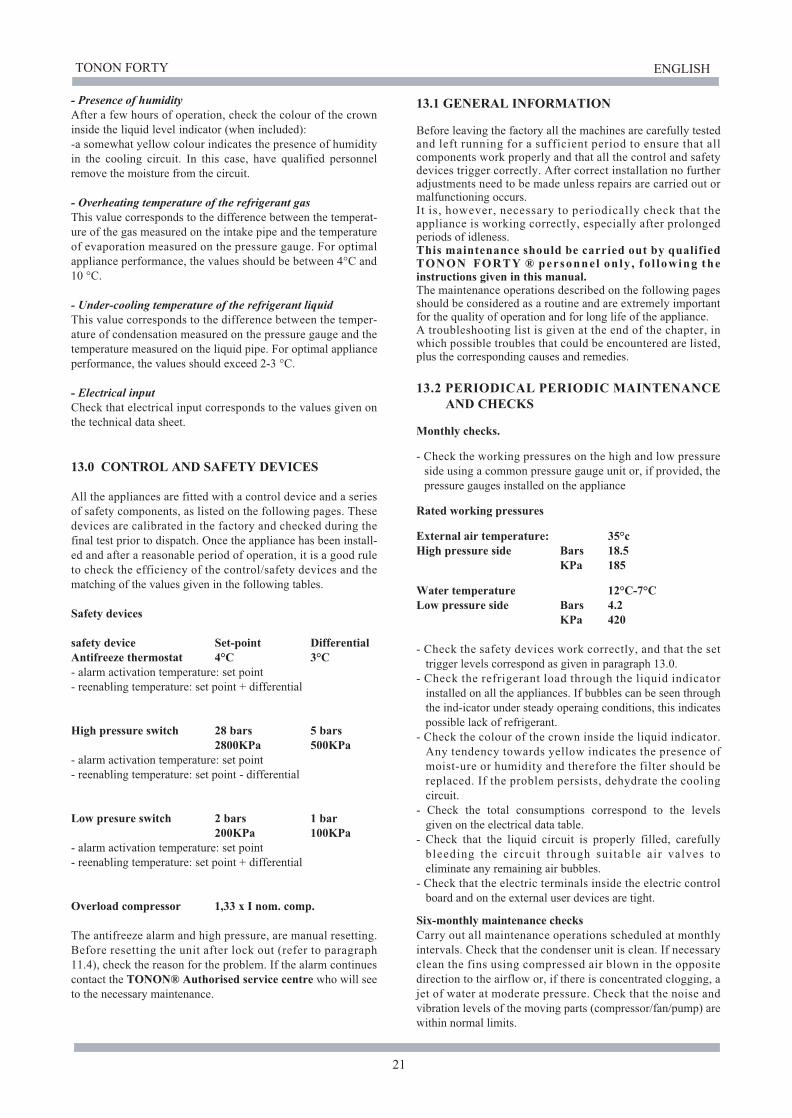
- Presence of humidity
After a few hours of operation, check the colour of the crown
inside the liquid level indicator (when included):
-a somewhat yellow colour indicates the presence of humidity
in the cooling circuit. In this case, have qualified personnel
remove the moisture from the circuit.
- Overheating temperature of the refrigerant gas
This value corresponds to the difference between the temperat-
ure of the gas measured on the intake pipe and the temperature
of evaporation measured on the pressure gauge. For optimal
appliance performance, the values should be between 4°C and
10 °C.
- Under-cooling temperature of the refrigerant liquid
This value corresponds to the difference between the temper-
ature of condensation measured on the pressure gauge and the
temperature measured on the liquid pipe. For optimal appliance
performance, the values should exceed 2-3 °C.
- Electrical input
Check that electrical input corresponds to the values given on
the technical data sheet.
13.0 CONTROL AND SAFETY DEVICES
All the appliances are fitted with a control device and a series
of safety components, as listed on the following pages. These
devices are calibrated in the factory and checked during the
final test prior to dispatch. Once the appliance has been install-
ed and after a reasonable period of operation, it is a good rule
to check the efficiency of the control/safety devices and the
matching of the values given in the following tables.
Safety devices
safety device Set-point Differential
Antifreeze thermostat 4°C 3°C
- alarm activation temperature: set point
- reenabling temperature: set point + differential
High pressure switch 28 bars 5 bars
2800KPa 500KPa
- alarm activation temperature: set point
- reenabling temperature: set point - differential
Low presure switch 2 bars 1 bar
200KPa 100KPa
- alarm activation temperature: set point
- reenabling temperature: set point + differential
Overload compressor 1,33 x I nom. comp.
The antifreeze alarm and high pressure, are manual resetting.
Before resetting the unit after lock out (refer to paragraph
11.4), check the reason for the problem. If the alarm continues
contact the TONON® Authorised service centre who will see
to the necessary maintenance.
13.1 GENERAL INFORMATION
Before leaving the factory all the machines are carefully tested
and left running for a sufficient period to ensure that all
components work properly and that all the control and safety
devices trigger correctly. After correct installation no further
adjustments need to be made unless repairs are carried out or
malfunctioning occurs.
It is, however, necessary to periodically check that the
appliance is working correctly, especially after prolonged
periods of idleness.
This maintenance should be carried out by qualified TONON FORTY ® personne l on ly , fo l lowing the instructions given in this manual.The maintenance operations described on the following pages
should be considered as a routine and are extremely important
for the quality of operation and for long life of the appliance.
A troubleshooting list is given at the end of the chapter, in
which possible troubles that could be encountered are listed,
plus the corresponding causes and remedies.
13.2 PERIODICAL PERIODIC MAINTENANCE
AND CHECKS
Monthly checks.
- Check the working pressures on the high and low pressure
side using a common pressure gauge unit or, if provided, the
pressure gauges installed on the appliance
Rated working pressures
External air temperature: 35°c
High pressure side Bars 18.5
KPa 185
Water temperature 12°C-7°C
Low pressure side Bars 4.2
KPa 420
- Check the safety devices work correctly, and that the set
trigger levels correspond as given in paragraph 13.0.
- Check the refrigerant load through the liquid indicator
installed on all the appliances. If bubbles can be seen through
the ind-icator under steady operaing conditions, this indicates
possible lack of refrigerant.
- Check the colour of the crown inside the liquid indicator.
Any tendency towards yellow indicates the presence of
moist-ure or humidity and therefore the filter should be
replaced. If the problem persists, dehydrate the cooling
circuit.
- Check the total consumptions correspond to the levels
given on the electrical data table.
- Check that the liquid circuit is properly filled, carefully
bleeding the circuit through suitable air valves to
eliminate any remaining air bubbles.
- Check that the electric terminals inside the electric control
board and on the external user devices are tight.
Six-monthly maintenance checks
Carry out all maintenance operations scheduled at monthly
intervals. Check that the condenser unit is clean. If necessary
clean the fins using compressed air blown in the opposite
direction to the airflow or, if there is concentrated clogging, a
jet of water at moderate pressure. Check that the noise and
vibration levels of the moving parts (compressor/fan/pump) are
within normal limits.

TONON FORTY ENGLISH
22
13.3 STOPPING FOR THE SEASON
The Quasar and Pulsar range chillers and heat pumps are
normally used in civil type air-conditioning systems which
remain idle during Winter.
If the appliance is installed in areas where there is the poss-
ibility of freezing during winter, the system must be drain-
ed of water or the latter mixed with anti-freeze solutions in
suitable percentage parts. In this case appliance efficiency
may be slightly affected and the size of the pump should be
calculated taking into consideration the variation in the
parameters of water flow rate and loss of head of the cooler
(see table par. 2.3).
IMPORTANT: FOR UNITS WITH EVAPORATOR
ANTIFREEZE ELEMENTS, DO NOT TURN THE
POWER OFF TO THE UNIT TO AVOID THE SAFETY
DEVICE BEING TURNED OFF DURING COLD
PERIODS
The antifreeze elements are active even when the unit is
on stand-by.
13.4 SAFETY INFORMATION
All maintenance, repairs and replacement operations to any
component, adding refrigerant gas, dismantling the unit, must
all be done by qualified personnel trained in air conditioning
units.
Electric connections
Fit a differential automatic switch near to the unit, with ade-
quate capacity for the electric intake. Connect the unit to
earth, checking it is efficient (80 ).
Refrigerant fluids
The type of refrigerant to use is given on the technical data
plate on the hydraulic attachment side of the unit. The lubri-
fication oil to be uses is given on the compressor plate.
Warnings
If the refrigerant gas accidentally leaks, take the following
precautions:
- if the refrigerant gas comes into contact with skin or eyes, it
can cause frostbite. Therefore, use protective gloves and
clothing, and protect the face and eyes.
Prolonged inhalation of refrigerant gas can cause uncon-
sciousness or heart disorders. Elevated concentrations can
cause asphyxia due to the lack of oxygen in the surrounding
atmosphere.
- Never use open flames, which due to combustion can cause
toxic substances.
13 .5 DEMOLISHING THE MACHINE AND
DISPOSAL OF TOXIC SUBSTANCES
Demolition and processing of the substances used in the
machine must be entrusted to authorised persons, in accord-
ance with legislation in force. Harmful substances like comp-
ressor oil and refrigerant, must not be emptied directly into
the atmosphere, but collected in special containers and de-
livered to the special disposal centres. all the identification
plates and technical documents must be destroyed.

TONON FORTY ENGLISH
23
14.0 FAILURE SOLVER
FAILURE SIGN POSSIBLE CAUSE RECOMMENDED REMEDY
Power supply failure
Unit in STAND_BY mode
Writing OFF on the display No external consent
Timing in progress
The machine
does not start
Too little refrigerant
Replace the filter
Excessive heat charge
Reset or repair the thermostat
Too little refrigerant
Service the compressor
Service the compressor
Liquid return
Display panel does not light up
The display panel is lit but the
machine does not start
The machine does not start and
the compressor LED blinks on the
display panel
The low part of the display blinks
with one or more alphanumeric
codes and alternates with the
temperature level
One or more satefy devices is in
alarm status
Phses inverted. Relay KA3 does not
give an impusle. The related LED is
not active (only mod. 041)
Change the input phases in the terminal
block in the electric panel
Check electric connections to the mains
supply terminals and the tension values.
Check the fuses on the secondary circuit
of the auxiliary transformer
See par. 6.3 to start the equipment
Check connections to
terminals 2-3 for external
Wait for timing to finish (max. 360
sec.);then the compressor should
start
Check which safety device has
triggered, remove the cause for
the alarm and rearm the safety
device (see par. 9.6)
The compressor
continuously starts
and stops
Normal working, too frequent
stops and starts due to low
pressure
Suction pressure too low and
frostLiquid line filter blocked
Trace and remove the refrigerant
leak and fill up
The compressor
runs and never
stops
Temperature too high in the
room being conditioned
Temperature too low in the
room being conditioned
Bubbles on the refrigerant
passage indicator
The thermostat starts at too low
temperature
Check infiltrations and insulation
Trace and repair the refrigerant
leakage and fill up
Noisy compressor
The compressor is noisy, or
delivery pressure too low and
suction pressure too high
The compressor knocks in the
head.
The suction pipe is abnormally
cold
Worn or broken compression coils
in the compressor
Broken parts inside the compressor
Expansion valve blocked in
open position
Check overheating and the bulb
position in the expansion valve
Repair or replace the expansion
valve

TONON FORTY ENGLISH
24
FAILURE SIGN POSSIBLE CAUSE
Thermostatic valve whistlesAdd refrigerant
Blocked filter or solenoid Clean or replace
Repair or replace
Overheating not correctly adjusted
Excessive overheating
Dirty condenser
Excessive load to the evaporator
Repair or replace the valve
Noisy compressor Service the compressor
System performance
is lower
than normal
Temperature difference in the
refrigerant pipe on a level with
the filter or expansion valve
Intermittent or uninterrupted
running
The liquid refrigerant vaporises
Blocked or obstructed expansion
valve
Excessive pressure drop in
evaporator
RECOMMENDED REMEDY
Delivery pressure
too high
Condensator outlet air too hot
Condenser outlet air cold
Poor condensation air flow
Too much refrigerant in the circuit,
condenser flooded
Adjust the expansion valve and
check
Check overheating and reset the
expansion valve
Check the fan condition and any
obstacles in the air flow
Remove anything that is blocking
the condenser (leaves, paper, etc)
Empty the refrigerant from the
condenser
Suction pressure
too high
Compressor runs without
stopping
Suction pipes too cold
Liquid return to the
compressor
Expansion valve overloaded
Expansion valve blocked in the
open position
Broken compression coils in the
compressor
Check there are no excessive
outside air infiltrations into the
conditioned room
Set the overheating level and
check the bulb position

TONON FORTY ENGLISH
25
LEGEND
M1 * Compressor
SAE
FD
* External air exchanger
VTE
* Filtro deidratatore
MCI
HP
* Thermostatic valve
LP
* Plant interface compact module
1 -
* High pressure safety switch
MHP
* Low pressure safety switch
MLP
* Pressure connection
B1
* High pressure gauge (optional)
B2
* Low pressure gauge (optional)
B3
* Working temperature sensor
EV1
* Antifreeze temperature sensor
VNR
* Condensation control temperature sensor
W1- water back from the palnt
W2- water to the plant
1
2
3
3
3
3
3
3
4
5
5
6
8
8
7
Boiler plantWater discharge in condensation
tank
Water inlet Water oulet
IN
OUT
COMPONENTS TO BE INSTALLED BY AN INSTALLER ON SITE
1. Quasar / Pulsar
2. User's system
3. Cock
4. Circulation pump
5. 3-way valve
MCI Plant interface compact module
VS Safety valve
VE Expansion tank
6. Net filter
8. Vibration damping coupling
7. Manual air blow valve
FL Flow switch
1
1
18
1
B2
2
W1W2
W1 W2
T
T
T
T
T T
TT
** Cycle inversion valve
** Non-return valve
2 - ** Tank for liquid
3 - * Pressure connection for pressure trasducer
T
Mod. Quasar
Mod. Pulsar
* Quasar e Pulsar
** Pulsar
M3
FL
MCI
VE
VS
M3 Circulation pump
MAIN HYDRAULIC COMPONENTS
M1
M1
SAE
SAE
FD
B2B1
> HP
< LP
MHP
MLP
MCIVTE
B3
1
> HP MHP
1
< LP
MLP
FD
VNR
VNRVTE
VTE
B3
B1
MCI
EV1
RC
15.0 GENERAL HYDRAULIC DIAGRAMGeneral plant of a Quasar chiller or Pulsar heat pump paired to a boiler
16.0 COOLING CIRCUIT DIAGRAM

TONON FORTY ENGLISH
26
A1
DIS
PL
AY
MIC
RO
PR
OC
ES
SO
R C
ON
TR
OL
LE
R
12
AC
AL
LG
ND
ST3
ST2
ST1
12DC
GND
ID5
ID4
ID3
ID2
ID1
CR1-R2
R1
R2
CR3-R4
R3
R4
IN TC
OUT TC
RE
MO
TE
KE
YB
OA
RD
COMP
PUMP
VALVE
HEATER
1 9
2 3
6 8 7 1
0 4
1
2 13 14 1
5 1
6
7 6
5 2
1
L-0
H-0
U-0
O-0
T-0
R-0
M-0
V-0
S-2
AA0
AB0
AC0
Z-0
Y-0
D-5
X-0
AF0
AG0
AH0
D-4
AD0
PE
L1
N
GV1
L
N
1
4
2
3
QM
1
A-0
/A-1
N-0
/N-1
A-1
D-0
D-2
A-0
N-3
F-0T1
KM
1
C1
C-0B-0
C2 P
-0
C-0
GV0
P-0
AD0
GV2
AF0
N-6
GV0
V-0
T-0
R-1
U-0
Q-0
AC0
Z-0
S-1
Y-0
E-0
GV2
N-5
N-6
GV0
AG0
AH0
GV1
M1M
1M
1 M2
M1 M
3T
PB
3B
2B
1F
LL
PH
PR
CE
V1
RA
KM
1
D-0
D-2
D-3
D-1
E-0
X-0
N-4
D-4
D-5
L-0
/L-1
S-0/S-2
AA0
AB0
M-0
H-1
L-1
4
5
6
7
8
9
1
2
1+
2
-
kR
C b
ase
KR
C T
op
COM
SR
S
I
ON
EST/IN
ALLARME
12Vac
12Vac
13
PE
10
1
2
11
P
E
CS
R
PE
MN
B
PE
LN
PE
3
1
2
3
1
2
3
1
2
3
1
2
3
1
2
3
1
2
3
1
2
3
1
2
3
1
2
3
1
2
1
2
1
2
1
2
1
2
1
2
1
2
FU
2
(1 A
-T)
FU
1
(6,3
A-T
)
CONN_1
CONN_2
CONN_3
CONN_4
CONN_5
CONN_6
CONN_7
CONN_8
CONN_9
CONN_10
OUT
+12
1
2
1
2
1
2
1
2
BL
UE
RE
D
BL
AC
K
N-5/N-6
N-2/N-3
H-0
/H-1
N-0/N-3
N-0/N-3
N-4
/N-5
R-0/R-1
R-1/R-1
S-0/S-1
S-1/S-1
K
M1
17.0 ELECTRIC DIAGRAM MODELS Quasar/Pulsar 021-026-031
Power supply 230v/50Hz
20
2
1
B4
m.a.Ch.
m.a.Ch.
Po
wer
su
pp
lyL
EG
EN
D
- A
1 M
icro
pro
cessor
contr
oll
er
- B
1 M
ain
sensor
- B
2 A
nti
-fre
eze s
ensor
- B
3 C
ondensati
on c
ontr
ol
sensor
- B
4 E
xte
rnal
air
tem
pera
ture
sensor
(O
pti
onal
on r
equest)
- C
1 C
om
pre
ssor
capacit
or
- C
2 V
enti
lato
r capacit
or
- E
V1 R
evers
e c
ycle
sole
noid
- F
L F
low
sw
itch (
wate
r fl
ow
safe
ty)
- F
U1 A
uxil
iary
cir
cuit
s f
use 2
30V
- F
U2 A
uxil
iary
cir
cuit
s f
use 2
4V
- H
P H
igh p
ressure
sw
itch
- L
P L
ow
pre
ssure
sw
itch
- K
M1 C
om
pre
ssor
conta
cto
r
- M
1 C
om
pre
ssor
moto
r
- M
2 V
enti
lato
r m
oto
r
- M
3 P
um
p m
oto
r
- Q
M1 M
ain
sw
itch
- R
A A
nti
-fre
eze h
eate
r
- R
C H
ousin
g h
eate
r
- T
P P
ressure
tra
sducer
- K
RC
BA
SE
Connecti
on k
it f
or
rem
ote
contr
ol
- K
RC
Top C
onnecti
on k
it f
or
rem
ote
contr
ol
- S
R O
n/O
ff r
em
ote
contr
ol
- S
I S
um
mer/
win
ter
rem
ote
contr
ol
CO
NN
EC
TO
R L
IST
No.
TY
PE
LO
AD
IN
ITIA
LS
C
OL
OU
R
ST
AN
DA
RD
O
PT
ION
AL
1
3 p
ole
s 2
30V
C
ircula
tion p
um
p
M
3
Whit
e
Yes
N
o
2
3 p
ole
s 1
2V
C
ondensati
on c
ontr
ol
sensor
B3
Gre
en
Yes
N
o
2
3 p
ole
s 1
2V
C
ondensati
on c
ontr
ol
trasducer
TP
G
reen
No
Y
es
3
2 p
ole
s 1
2V
F
rost
pro
tecti
on s
ensor
B
2
Red
Yes
N
o
4
2 p
ole
s 1
2V
M
ain
sensor
B1
Blu
e
Yes
N
o
5
2 p
ole
s 1
2V
F
low
sw
itch
F
L
Bla
ck
Yes
N
o
6
2 p
ole
s 1
2V
L
ow
pre
ssure
sw
itch
L
P
Gre
en
Yes
N
o
7
2 p
ole
s 1
2V
H
igh p
ressure
sw
itch
H
P
Whit
e
Yes
N
o
8
3 p
ole
s 2
30V
C
om
pre
ssor
housin
g h
eate
r R
C
Bla
ck
*Y
es
Y
es
9
3 p
ole
s 2
30V
C
old
cycle
invers
ion s
ole
noid
E
V1
Red
*Y
es
N
o
10
3 p
ole
s 2
30V
A
nti
-fre
eze h
eate
r
RA
B
lue
No
Y
es
* P
uls
ar
models

TONON FORTY ENGLISH
27
A1
DIS
PL
AY
MIC
RO
PR
OC
ES
SO
R C
ON
TR
OL
LE
R
12
AC
AL
LG
ND
ST3
ST2
ST1
12DC
GND
ID5
ID4
ID3
ID2
ID1
CR1-R2
R1
R2
CR3-R4
R3
R4
IN TC
OUT TC
SE
RIA
L R
S232
RE
MO
TE
KE
YB
OA
RD
COMP
PUMP
VALVE
HEATER
1 9
2
3 6
8 7 1
0 4
12 13 14 1
5 16
7
6 5 2
1 9 4
L-0
H-0
U-0
O-0
T-0
R-0
M-0
V-0
S-2
AA0
AB0
AC0
Z-0
Y-0
D-5
X-0
AF0
AG0
AH0
D-4
AD0
3 1
2
3 1
2
3P VERDE
1
2
1
2
2P ROSSO
2P VERDE
2P BIANCO
3P NERO
3P ROSSO
3P BLU
1
2
1
2
1
2
1
2
1
2
1
2
2P NERO
2P BLU
M3
TP
B3
B2
B1
FL
LP
HP
RC
EV
1R
A
1+
2
-
COM
SR
S
I
ON
EST/IN
ALLARME
12Vac
12Vac
4 5
6
7 8
9
1 2
S-0/S-2
AA0
AB0
M-0
H-1
L-1
S-0/S-1
AC0
S-1/S-1
Z-0
S-1
Y-0
E-0
GV2
N-5
N-6
GV0
AG0
AH0
GV1
N-5/N-6
3 1
2
3 1
2
3P BIANCO
M1
M 1
M
1 M2
M1
P
E 1
0 12 1
1 P
E
CS
RM
NB
PE
LN
PE
V-0
T-0
R-1
R-1
U-0
Q-0
R-0/R-1
C2
P-0
AD0
GV2
AF0
N-6
GV0
GV0
13
KM
1
N-2
D-2/D-3/D-4
H-0
/H-1
L-0
/L-1
F-0
T1
N-1
D-2D-0
KA
3
KA
3
11
14
A-1
/A-2
C-1
B-1
A-2
1 3 5
2 4 6
QM
1
L3
L2
L1
GV1
N-0/N-2
E-0
PE
KM
1
L1
L2
L3
N
3 1
2
3 1
2
3 1
2
3 1
2
3 1
2
3 1
2
1
2
1
2
FU
1
(6,3
A-T
)
FU
2
(1 A
-T)
D-0/D-1
KM
1
N-0/N-1
N-2/N-3
A-0/A-1
B-0/B-1
C-0/C-1
18.0 ELECTRIC DIAGRAM MODELS Quasar/Pulsar 041
Power supply 400v/50Hz
20
2
1
B4
kR
C b
ase
KR
C T
op
Pow
er
supply
LE
GE
ND
- A
1 M
icro
pro
cessor
contr
oll
er
- B
1 M
ain
sensor
- B
2 A
nti
-fre
eze s
ensor
- B
3 C
ondensati
on c
ontr
ol
sensor
- B
4 E
xte
rnal
air
tem
pera
ture
sensor
(O
pti
onal
on r
equest)
- C
1 C
om
pre
ssor
capacit
or
- C
2 V
enti
lato
r capacit
or
- E
V1 R
evers
e c
ycle
sole
noid
- F
L F
low
sw
itch (
wate
r fl
ow
safe
ty)
- F
U1 A
uxil
iary
cir
cuit
s f
use 2
30V
- F
U2 A
uxil
iary
cir
cuit
s f
use 2
4V
- H
P H
igh p
ressure
sw
itch
- L
P L
ow
pre
ssure
sw
itch
- K
M1 C
om
pre
ssor
conta
cto
r
- M
1 C
om
pre
ssor
moto
r
- M
2 V
enti
lato
r m
oto
r
- M
3 P
um
p m
oto
r
- Q
M1 M
ain
sw
itch
- R
A A
nti
-fre
eze h
eate
r
- R
C H
ousin
g h
eate
r
- T
P P
ressure
tra
sducer
- K
RC
BA
SE
Co
nn
ecti
on
kit
for
rem
ote
contr
ol
- K
RC
Top C
onnecti
on k
it f
or
rem
ote
contr
ol
- S
R O
n/O
ff r
em
ote
contr
ol
- S
I S
um
mer/
win
ter
rem
ote
contr
ol
CO
NN
EC
TO
R L
IST
No.
TY
PE
LO
AD
IN
ITIA
LS
C
OL
OU
R
ST
AN
DA
RD
O
PT
ION
AL
1
3 p
ole
s 2
30V
C
ircula
tion p
um
p
M
3
Whit
e
Yes
N
o
2
3 p
ole
s 1
2V
C
ondensati
on c
ontr
ol
sensor
B3
Gre
en
Yes
N
o
2
3 p
ole
s 1
2V
C
ondensati
on c
ontr
ol
trasducer
TP
G
reen
No
Y
es
3
2 p
ole
s 1
2V
F
rost
pro
tecti
on s
ensor
B
2
Red
Yes
N
o
4
2 p
ole
s 1
2V
M
ain
sensor
B1
Blu
e
Yes
N
o
5
2 p
ole
s 1
2V
F
low
sw
itch
F
L
Bla
ck
Yes
N
o
6
2 p
ole
s 1
2V
L
ow
pre
ssure
sw
itch
L
P
Gre
en
Yes
N
o
7
2 p
ole
s 1
2V
H
igh p
ressure
sw
itch
H
P
Whit
e
Yes
N
o
8
3 p
ole
s 2
30V
C
om
pre
ssor
housin
g h
eate
r R
C
Bla
ck
*Y
es
Y
es
9
3 p
ole
s 2
30V
C
old
cycle
invers
ion s
ole
noid
E
V1
Red
*Y
es
N
o
10
3 p
ole
s 2
30V
A
nti
-fre
eze h
eate
r
RA
B
lue
No
Y
es
* P
uls
ar
models

TONON FORTY ENGLISH
28
021 026 031 041 021 026 031 041
A1 Microprocessor controller with display mach_1 735000980 1 1 1 1 1 1 1 1
B1 Work probe 735000830 1 1 1 1 1 1 1 1
B2 Anti-freeze probe 735000830 1 1 1 1 1 1 1 1
B3 Condensation probe 735000830 1 1 1 1 1 1 1 1
SPARE PARTS LIST
MARK DESCRIPTION CODEQuasar Pulsar
KM1 Compressor contactor 4kW-AC3 721000240 1 1
1
1 1 1
1
1
M2 Axial fan 730000180 1 1 1 1 1 1 1 2
731000030 1 1 1 1
731000080 1 1 1 1
670103340 1 1 1 1
670103350 1 1 1 1
Mains Magnetothermal protection 2P 16A 710001110 1 1 1 1
Mains Magnetothermal protection 2P 20A 710001130 1 1
Mains Magnetothermal protection 3P 10A 710001100 1 1
Overload cut-out 710000700
RC Compressor oil sump heating element 729000010 1 1 1 1
425100940 1 1
425101030 1 1
425100950 1 1
425101041 1 1
T1 Auxiliary circuit transformer 230/12V 5VA 451350270 1 1 1 1 1 1 1 1
VE Expansion tank 426000050 1 1 1 1
VS 3 bar safety valve 428200010 1 1 1 1 1 1 1 1
VNR Check valve 418300150 2 2 2 2
435300320 1 1 1 2 2 2
435300340 1 2
External battery
VTE Thermostat valve
Circulating pump motorM3
Compatto module for plant interface
QM1
SAE
MCI
728100210 1 1
728100220 1 1
728100230 1 1
728100510 1 1
Scroll CompressorM1
714000020 1 1
714000030 1 1
714000040 1 1
Compressor condenser C1
C2 Fan condenser 730000200 1 1 1 1 1 1 1 2
418500010 1 1
418500020 1 1
Coil + cable 230V 721300010 1 1 1 1
FD Dehydrator filter to be welded 435100170 1 1 1 1 1 1 1 1
FL Flow switch 3/4" 282006000 1 1 1 1 1 1 1 1
HP 28bar High pressure switch 720100230 1 1 1 1 1 1 1 1
LP Low pressure switch 720100180 1 1 1 1 1 1 1 1
KA3 Phase sequence control relay 720100130 1 1
Reverse cicle splenoid EV1
Compressor contactor 5,5 kW-AC3 721000210
***A1 Microprocessor controller with display mach_1
with integrated clock (optional)
735000990 optional on all the units