
20140902 Prayoudh-01 Scandal Purchasing 2013-0517 BO DCNM Brochure US LR
description
Technical Guide to SRAN Network Design (GO Applicable to the SRAN10.0 & GBSS17.0 & BSC6910)
CONFIDENTIAL
Product Name Confidentiality Level
GSM BSC6910 Internal Public
Product VersionTotal 258 pages
V900R017C00
Technical Guide to SRAN Network Design (GO Applicable to SRAN10.0 & GBSS17.0 &
BSC6910) (For internal use only)
Prepared By fuqiang (employee ID:00283077) Date 2014-07-18
Reviewed By lishuanghua (employee ID: 00101863)Li Yongqing (employee ID: 00141602)chenyin (employee ID: 00179448)Hu Chunhua (employee ID: 00257638)
Date 2014-07-28
Approved By hepeng (employee ID: 00110002) Date 2014-09-03
Huawei Technologies Co., Ltd.All rights reserved

Technical Guide to SRAN Network Design (GO Applicable to the SRAN10.0 & GBSS17.0 & BSC6910)
CONFIDENTIAL
Change History
Version Prepared/Reviewed By
Date Description Approved By
V0.1 Li Bo 2012-11-30 Initial draft Mei Weifeng, Huang Yanzhong
V0.2 Li Bo 2012-12-07 The document is modified according to comments of the delivery department.
Mei Weifeng
V0.3 Li Bo 2012-12-15 The document is modified according to comments of the network information service (NIS) department.
Mei Weifeng
V0.4 Li Bo 2012-12-22 The document is modified according to review comments.
Mei Weifeng
V0.5 Li Bo 2013-2-4 Section 18.2.2 "Design Examples" is modified.
Songruining
V0.6 Li Bo 2013-5-7 Add a note about the relationship between traffic model and BSC specification in the contract:Specifications and capacity configuration of the BSC must be based on a certain traffic model, all contracts must be established on a given traffic model to ensure the accuracy of the contract. If you are unable to obtain
Songruining
2023-04-22 Huawei Confidential Page 2 of 258
Technical Guide to SRAN Network Design (GO Applicable to the SRAN10.0 & GBSS17.0 & BSC6910)
CONFIDENTIAL
Version Prepared/Reviewed By
Date Description Approved By
accurate traffic model, we recommend using the default Huawei traffic model for the contract traffic model.
V0.7 Tang Xiaoli 2013-06-19 Deleted eGSM and used the eGBTS to replace independent NE.
Songruining
V0.8 Tang Xiaoli 2013-07-30 Added section 19.3 "A Interface Design (TDM)" and section 19.6 "Abis InterfaceDesign (IP over E1)."
Songruining
V0.9 Tang Xiaoli 2013-11-22 Updated the document to adapt to the GBSS16.0 version.
Songruining
V1.0 Tang Xiaoli 2014-03-03 Revised the document based on TR5 review comments.
Songruining
V1.1 Liuqi 2014-05-06 Add 22.5.2 Constraints
Songruining
V1.2 付强 2014.07.18 Add VAMOS FRAdd 16.4 source IP route
Songruining
2023-04-22 Huawei Confidential Page 3 of 258
Technical Guide to SRAN Network Design (GO Applicable to the SRAN10.0 & GBSS17.0 & BSC6910)
CONFIDENTIAL
Contents
Foreword........................................................................................191.1 Objectives.....................................................................................................................................................................191.2 Scope............................................................................................................................................................................201.3 Constraints....................................................................................................................................................................201.4 Dependency..................................................................................................................................................................20
2 Overview of Network Design........................................................213 Overall Guidance Principles..........................................................224 Overview of Key NEs....................................................................235 Overview of the Network Design Tool............................................246 Important Reference Document....................................................257 Product Specifications..................................................................267.1 BSC Specifications.......................................................................................................................................................267.1.1 Hardware Capacity....................................................................................................................................................267.1.2 Estimation of BSC Configuration Capacity..............................................................................................................277.2 Board Specifications.....................................................................................................................................................287.2.1 BSC6910 Board Specifications.................................................................................................................................287.2.2 Service Processing Modules......................................................................................................................................287.2.3 Interface Modules......................................................................................................................................................31
8 BOQ Review Guide.......................................................................348.1 Design Overview..........................................................................................................................................................348.1.1 Purpose of the Design................................................................................................................................................348.1.2 Input of the Design....................................................................................................................................................348.1.3 Contents of the Design..............................................................................................................................................348.1.4 Design Reference.......................................................................................................................................................348.2 Overview of Pre-sales Network Design.......................................................................................................................348.3 BOQ Review Principles...............................................................................................................................................358.4 CS Traffic Models........................................................................................................................................................368.5 PS Traffic Models.........................................................................................................................................................388.6 Relationship Between Traffic Model and Traffic Statistics..........................................................................................40
2023-04-22 Huawei Confidential Page 4 of 258
Technical Guide to SRAN Network Design (GO Applicable to the SRAN10.0 & GBSS17.0 & BSC6910)
CONFIDENTIAL
9 Parameters for Capacity Calculation.............................................4210 Capacity Calculation...................................................................4211 Design of Resource Allocation.....................................................4411.1 Design Overview........................................................................................................................................................4411.1.1 Purpose of the Design..............................................................................................................................................4411.1.2 Input of the Design..................................................................................................................................................4511.2 BSC Load Allocation..................................................................................................................................................4511.2.1 Signaling Storm.......................................................................................................................................................4611.3 BSC Board Layout Design.........................................................................................................................................5211.3.1 Design Guide...........................................................................................................................................................52
12 Naming Rules Design.................................................................5812.1 Design Overview........................................................................................................................................................5812.1.1 Purpose of the Design..............................................................................................................................................5812.1.2 Input of the Design..................................................................................................................................................5812.2 NE Naming Rules.......................................................................................................................................................5812.2.1 Naming Rules of Areas............................................................................................................................................5812.2.2 Naming Rules of Offices.........................................................................................................................................5912.2.3 Naming Rules of Manufacturers.............................................................................................................................5912.2.4 Naming Rules of NEs..............................................................................................................................................6012.2.5 Naming Rules of Signaling Points..........................................................................................................................6112.3 NE Numbering Rules.................................................................................................................................................6112.3.1 Numbering Rules of Entity IDs...............................................................................................................................6112.3.2 Numbering Rules of BTS IDs.................................................................................................................................6212.3.3 Numbering Rules of Cell IDs..................................................................................................................................6212.3.4 Numbering Rules of LACs......................................................................................................................................6212.3.5 Numbering Rules of MCCs and MNCs...................................................................................................................6212.3.6 Numbering Rules of SPXs and DPXs.....................................................................................................................62
13 BSC6910 Networking Principles..................................................6313.1 Technical Principles....................................................................................................................................................6313.1.1 Overview.................................................................................................................................................................6313.1.2 Technical Specifications..........................................................................................................................................6713.1.3 Technical Description..............................................................................................................................................68
14 Optical Interface MSP.................................................................7014.1 MSP Design Guide.....................................................................................................................................................7014.1.1 STM-1 Tributary Mode Selection...........................................................................................................................7014.1.2 MSP Mode Selection...............................................................................................................................................7014.1.3 Parameter Configuration.........................................................................................................................................7114.1.4 S1 Configuration.....................................................................................................................................................7214.1.5 C2 Configuration.....................................................................................................................................................7314.1.6 MSP Support Capabilities of Boards.......................................................................................................................73
2023-04-22 Huawei Confidential Page 5 of 258

Technical Guide to SRAN Network Design (GO Applicable to the SRAN10.0 & GBSS17.0 & BSC6910)
CONFIDENTIAL
14.2 MSP Technical Description........................................................................................................................................74
15 Detection Mechanism.................................................................8015.1 Restrictions of the Design..........................................................................................................................................8015.2 BFD Detection............................................................................................................................................................8215.3 ARP Detection............................................................................................................................................................8415.4 IP PM Detection.........................................................................................................................................................84
16 IP Interworking Design...............................................................8616.1 IP Planning on the BSC Side......................................................................................................................................8616.2 IP Planning on the BTS Side......................................................................................................................................8716.3 Routing Design on the BSC Side...............................................................................................................................8816.4 Routing Design on the BTS Side................................................................................................................................8816.5 VLAN Design.............................................................................................................................................................8816.6 QoS Design.................................................................................................................................................................89
17 Network Topology Design...........................................................9117.1 Design Overview........................................................................................................................................................9117.1.1 Purpose of the Design..............................................................................................................................................9117.1.2 Input of the Design..................................................................................................................................................9117.2 Network Structure Design..........................................................................................................................................9117.2.1 Design Guide...........................................................................................................................................................9117.2.2 Typical Networking.................................................................................................................................................92
18 Reliability Design.....................................................................10218.1 Design Overview......................................................................................................................................................10218.1.1 Purpose of the Design............................................................................................................................................10218.1.2 Input of the Design................................................................................................................................................10218.2 Network Reliability Design......................................................................................................................................10218.2.1 Design Guide.........................................................................................................................................................10218.2.2 Design Examples...................................................................................................................................................103
19 Transmission Interface Design..................................................11819.1 Design Overview......................................................................................................................................................11819.1.1 Purpose of the Design............................................................................................................................................11819.1.2 Input of the Design................................................................................................................................................11819.2 A Interface Design....................................................................................................................................................11819.2.1 Interface Description.............................................................................................................................................11819.2.2 Networking Design................................................................................................................................................11919.2.3 SCTP Multi-Homing Design.................................................................................................................................12919.2.4 Signaling Bandwidth Calculation..........................................................................................................................13519.2.5 Signaling Configuration Principles.......................................................................................................................13519.2.6 Traffic Bandwidth Calculation..............................................................................................................................13519.2.7 IP Address Planning (A over IP)............................................................................................................................13619.2.8 Routing Planning (A over IP)................................................................................................................................138
2023-04-22 Huawei Confidential Page 6 of 258
Technical Guide to SRAN Network Design (GO Applicable to the SRAN10.0 & GBSS17.0 & BSC6910)
CONFIDENTIAL
19.2.9 QoS Design (A over IP).........................................................................................................................................13919.2.10 Interface Interworking.........................................................................................................................................14219.3 A Interface Design (TDM)........................................................................................................................................14419.3.1 Interface Description.............................................................................................................................................14419.3.2 Networking Design................................................................................................................................................14519.3.3 Transmission Bandwidth Design...........................................................................................................................14619.3.4 Signaling Configuration Principles.......................................................................................................................14619.4 Gb Interface Design..................................................................................................................................................14819.4.1 Interface Description.............................................................................................................................................14819.4.2 Networking Design................................................................................................................................................15019.4.3 Bandwidth Calculation..........................................................................................................................................15719.4.4 IP Address Planning...............................................................................................................................................15719.4.5 Routing Planning (Gb over IP)..............................................................................................................................15919.4.6 QoS Design (Gb over IP)......................................................................................................................................16019.4.7 Configuration Principles........................................................................................................................................16119.4.8 Interface Interworking...........................................................................................................................................16119.4.9 Interworking Instances..........................................................................................................................................16519.5 Abis Interface Design...............................................................................................................................................16819.5.1 Interface Description.............................................................................................................................................16819.5.2 Networking Design................................................................................................................................................16919.5.3 Bandwidth Calculation..........................................................................................................................................18019.5.4 IP Address Planning...............................................................................................................................................18319.5.5 Routing Planning...................................................................................................................................................18719.5.6 QoS Design............................................................................................................................................................18819.5.7 Abis Port Allocation Design..................................................................................................................................19119.6 Abis Interface Design (IP over E1)...........................................................................................................................19219.6.1 Interface Description.............................................................................................................................................19219.6.2 Networking Design................................................................................................................................................19219.6.3 Transmission Bandwidth Design...........................................................................................................................19419.6.4 Configuration Principles........................................................................................................................................19419.6.5 IP Planning............................................................................................................................................................19419.6.6 Route Planning......................................................................................................................................................19419.6.7 QoS Planning.........................................................................................................................................................19419.6.8 Clock Synchronization..........................................................................................................................................19519.7 Lb Interface Design..................................................................................................................................................19519.7.1 Interface Description.............................................................................................................................................19519.7.2 Function Interaction...............................................................................................................................................19619.7.3 Constraints and Limitations...................................................................................................................................19619.7.4 Networking Design................................................................................................................................................19619.7.5 Positioning Modes.................................................................................................................................................19719.7.6 Bandwidth Calculation..........................................................................................................................................19819.7.7 Parameter Design...................................................................................................................................................198
2023-04-22 Huawei Confidential Page 7 of 258
Technical Guide to SRAN Network Design (GO Applicable to the SRAN10.0 & GBSS17.0 & BSC6910)
CONFIDENTIAL
19.8 BTS Homing Allocation...........................................................................................................................................199
20 Clock Synchronization Design...................................................20120.1 Design Overview......................................................................................................................................................20120.1.1 Purpose of the Design............................................................................................................................................20120.1.2 Input of the Design................................................................................................................................................20120.2 Clock Description.....................................................................................................................................................20120.2.1 Definition of Synchronization...............................................................................................................................20120.2.2 SyncE.....................................................................................................................................................................20120.2.3 IEEE 1588 V2........................................................................................................................................................20220.2.4 Advantages and Disadvantages of Clock Protocols..............................................................................................20220.2.5 QoS Requirements of Clock Protocols..................................................................................................................20520.3 Clock Source Selection.............................................................................................................................................20520.4 Clock Design in Abis over TDM Mode...................................................................................................................20620.5 Clock Design in Abis over IP Mode.........................................................................................................................20720.6 Design of the IP Clock Server..................................................................................................................................209
21 Time Synchronization Design....................................................21421.1 Design Overview......................................................................................................................................................21421.1.1 Purpose of the Design............................................................................................................................................21421.1.2 Input of the Design................................................................................................................................................21421.2 Description of Time Synchronization.......................................................................................................................21421.3 NTP...........................................................................................................................................................................21421.4 Selection of a Time Synchronization Source............................................................................................................21521.5 Transmission Mode..................................................................................................................................................21521.6 Typical Networking..................................................................................................................................................21521.7 Typical Application...................................................................................................................................................216
22 Function Design.......................................................................21722.1 Design of Broadcast Solutions for Cells..................................................................................................................21722.1.1 Standard Broadcast................................................................................................................................................21722.1.2 Simple Cell Broadcast...........................................................................................................................................22222.2 Design of Radio Measurement Data Interface for Navigation (TOM-TOM)..........................................................22322.2.1 Overview...............................................................................................................................................................22322.2.2 Reference Document.............................................................................................................................................22422.2.3 Limitations on Specifications................................................................................................................................22422.2.4 Software and Hardware Configuration..................................................................................................................22422.2.5 Networking Design................................................................................................................................................22422.2.6 Bandwidth Design.................................................................................................................................................22722.2.7 Time Synchronization............................................................................................................................................22722.3 MOCN II Design......................................................................................................................................................22722.3.1 Overview...............................................................................................................................................................22722.3.2 Networking Design................................................................................................................................................22822.3.3 Capacity Planning..................................................................................................................................................228
2023-04-22 Huawei Confidential Page 8 of 258

Technical Guide to SRAN Network Design (GO Applicable to the SRAN10.0 & GBSS17.0 & BSC6910)
CONFIDENTIAL
22.3.4 Interface Design.....................................................................................................................................................22822.4 Design of BSC Node Redundancy...........................................................................................................................22922.4.1 Overview...............................................................................................................................................................22922.4.2 Constraints.............................................................................................................................................................23022.4.3 Networking Design................................................................................................................................................23322.4.4 Capacity Planning..................................................................................................................................................23322.4.5 Interface Design.....................................................................................................................................................23422.5 LCS Function Design...............................................................................................................................................239
23 BTS Design..............................................................................24323.1 BTS Cable Design....................................................................................................................................................24323.1.1 Purpose of the Design............................................................................................................................................24323.1.2 Input of the Design................................................................................................................................................24323.2 Design Tool of the BTS Cable Diagram...................................................................................................................24323.3 BTS Transmission Design........................................................................................................................................24323.3.1 Purpose of the Design............................................................................................................................................24323.3.2 BTS Transmission.................................................................................................................................................24323.3.3 eGBTS Networking...............................................................................................................................................246
24 OM Networking Design.............................................................24824.1 Design Overview......................................................................................................................................................24824.1.1 Input of the Design................................................................................................................................................24824.1.2 Design Content......................................................................................................................................................24824.1.3 Reference...............................................................................................................................................................24824.2 Introduction to OMU................................................................................................................................................24824.2.1 Standalone OMU...................................................................................................................................................24824.2.2 Dual OMU.............................................................................................................................................................24924.3 OM Networking Design...........................................................................................................................................25024.3.1 Networking for Part of E1/T1 Timeslots...............................................................................................................25024.3.2 Entire E1/T1 Networking......................................................................................................................................25224.3.3 IP Networking........................................................................................................................................................25324.3.4 Networking Instances............................................................................................................................................25424.4 OM IP Address Planning..........................................................................................................................................25524.5 Route Planning.........................................................................................................................................................25624.6 Impact of eGBTS on the O&M................................................................................................................................256
2023-04-22 Huawei Confidential Page 9 of 258
Technical Guide to SRAN Network Design (GO Applicable to the SRAN10.0 & GBSS17.0 & BSC6910)
CONFIDENTIAL
Figures
Figure 2-1 Position of the BSS network design in the entire network construction process................................21
Figure 11-1 Average service duration...................................................................................................................51
Figure 13-1 Port switchover..................................................................................................................................71
Figure 13-2 Board switchover...............................................................................................................................72
Figure 15-1 Diagram of the promoted commercial solution.................................................................................86
Figure 17-1 Networking of the BSC connected to a single MGW.......................................................................96
Figure 17-2 BSC/MGW multi-homing networking..............................................................................................97
Figure 17-3 MSC Pool networking mode 1..........................................................................................................98
Figure 17-4 MSC Pool networking mode 2..........................................................................................................99
Figure 17-5 Typical networking of the SGSN pool............................................................................................100
Figure 17-6 All-IP networking............................................................................................................................101
Figure 17-7 Typical IP-based networking...........................................................................................................101
Figure 17-8 Hybrid networking..........................................................................................................................102
Figure 17-9 Logical networking of the transmission resource pool...................................................................103
Figure 17-10 Physical networking of the transmission pool with active/standby boards...................................103
Figure 17-11 Physical networking of the transmission pool with independent boards......................................104
Figure 18-1 Improving reliability by active/standby links on ports....................................................................106
Figure 18-2 Reliability design of the Gb interface.............................................................................................107
Figure 18-3 Reliability design of IP transmission routes....................................................................................108
Figure 18-4 Reliability design of IP transmission routes....................................................................................108
Figure 18-5 BSC/MGW multi-homing networking............................................................................................109
Figure 18-6 MSC Pool networking mode 1........................................................................................................110
Figure 18-7 MSC Pool networking mode 2........................................................................................................111
Figure 18-8 Typical networking diagram of the SGSN pool..............................................................................112
Figure 18-9 IP networking topology of A interface boards based on the dynamic loading balancing...............112
Figure 18-10 Standalone EOMU........................................................................................................................113
2023-04-22 Huawei Confidential Page 10 of 258
Technical Guide to SRAN Network Design (GO Applicable to the SRAN10.0 & GBSS17.0 & BSC6910)
CONFIDENTIAL
Figure 18-11 Dual EOMUs.................................................................................................................................114
Figure 18-12 Clock subsystem of the BSC6910.................................................................................................115
Figure 18-13 BSC belonging to two layer-2 transmission devices in the dual-homing mode............................117
Figure 18-14 BSC belonging to one layer-2 transmission device in the single-homing mode...........................117
Figure 18-15 Inter-board link aggregation in the inter-board pool networking scenario....................................118
Figure 18-16 Manual active/standby LAGs on the BSC side+router adopting the VRRP networking mode....119
Figure 18-17 LAG of the active/standby board+router adopting the VRRP networking mode.........................120
Figure 19-1 Reference protocol model on the control plane of the A interface..................................................122
Figure 19-2 Reference protocol model on the user plane of the A interface......................................................122
Figure 19-3 BSC/MGW multi-homing networking............................................................................................123
Figure 19-4 Typical A over IP networking mode (pool of standalone boards)...................................................124
Figure 19-5 Typical A over IP networking mode (pool of standalone boards)...................................................126
Figure 19-6 Typical A over IP networking mode (pool of active/standby interface boards+dual-active ports). 128
Figure 19-7 Typical A over IP networking mode (pool of active/standby boards+manual active/standby LAGs).............................................................................................................................................................................129
Figure 19-8 SCTP four-homing between the BSC and the MSC server.............................................................133
Figure 19-9 Two M3UA links and SCTP four-homing between the BSC and the MSC server.........................134
Figure 19-10 SCTP dual-homing on the MSC server side and SCTP single-homing on the BSC side (1)........135
Figure 19-11 SCTP dual-homing on the MSC server side and SCTP single-homing on the BSC side (2)........136
Figure 19-12 SCTP single-homing on the MSC server side and SCTP dual-homing on the BSC side.............137
Figure 19-13 IP network topology of the BSC...................................................................................................141
Figure 19-14 Promoted detection mode in active/standby mode........................................................................143
Figure 19-15 Reference protocol model on the control plane of the A interface................................................148
Figure 19-16 Gb over IP protocol stack..............................................................................................................155
Figure 19-17 Embedded PCU networking..........................................................................................................156
Figure 19-18 Direction connection (Gb over IP)................................................................................................156
Figure 19-19 IP transmission network connection (Gb over IP)........................................................................157
Figure 19-20 Typical Gb over IP networking mode (active/standby boards+manual active/standby LAGs)....158
Figure 19-21 Typical Gb over IP networking mode (active/standby boards+dual-active ports)........................161
Figure 19-22 Logical connection between the NS layer and the SSGP layer.....................................................169
Figure 19-23 Abis over HDLC interface protocol..............................................................................................175
Figure 19-24 TDM networking when the Abis interface adopts STM-1 transmission.......................................177
Figure 19-25 IP networking when the Abis adopts MSTP transmission............................................................177
Figure 19-26 IP networking when the Abis adopts data network transmission..................................................177
2023-04-22 Huawei Confidential Page 11 of 258

Technical Guide to SRAN Network Design (GO Applicable to the SRAN10.0 & GBSS17.0 & BSC6910)
CONFIDENTIAL
Figure 19-27 BTS networking diagram..............................................................................................................178
Figure 19-28 Two E1s connected to different interface boards..........................................................................181
Figure 19-29 Two E1s connected to different ports on the same interface board...............................................181
Figure 19-30 Typical A over IP networking mode (pool of active/standby boards+manual active/standby LAGs+single IP address).....................................................................................................................................182
Figure 19-31 Typical A over IP networking mode (pool of active/standby boards+dual-active ports+single IP address)................................................................................................................................................................184
Figure 19-32 SMLC-based network topology for the Lb interface....................................................................203
Figure 19-33 Direct connection between the BSC and the SMLC.....................................................................204
Figure 19-34 Connection through STP...............................................................................................................204
Figure 20-1 Clock networking instance 1...........................................................................................................213
Figure 20-2 Clock networking instance 2...........................................................................................................213
Figure 20-3 MSTP-based GSM IP solution........................................................................................................216
Figure 20-4 IP Clock synchronization networking.............................................................................................217
Figure 21-1 Typical networking for time synchronization.................................................................................222
Figure 22-1 Network topology of the cell broadcast..........................................................................................225
Figure 22-2 Cable connection diagram between the interface board and the CBC............................................226
Figure 22-3 Topology of the simple cell broadcast system................................................................................230
Figure 22-4 Logical networking for the TOM-TOM..........................................................................................232
Figure 22-5 Physical networking on the VNP interface.....................................................................................233
Figure 22-6 Networking of the active/standby OMUs with a single port and directly connected routers.........233
Figure 22-7 Networking for time synchronization.............................................................................................234
Figure 22-8 Logical structure of the LCS system on the GSM network............................................................235
Figure 22-9 Logical structure of the NSS-based SMLC.....................................................................................237
Figure 22-10 Logical structure of the BSS-based SMLC...................................................................................237
Figure 22-11 LCS flow initiated by an external LCS client...............................................................................238
Figure 23-1 Networking topology change of the eGBTS...................................................................................243
Figure 23-2 Change of northbound and southbound interfaces of the eGBTS...................................................243
Figure 24-1 Standalone OMU.............................................................................................................................245
Figure 24-2 Dual OMUs.....................................................................................................................................246
Figure 24-3 25-pin D model interface.................................................................................................................247
Figure 24-4 Networking for part of E1/T1 timeslots..........................................................................................248
Figure 24-5 Entire E1/T1 Networking................................................................................................................249
Figure 24-6 OM network topology.....................................................................................................................249
2023-04-22 Huawei Confidential Page 12 of 258
Technical Guide to SRAN Network Design (GO Applicable to the SRAN10.0 & GBSS17.0 & BSC6910)
CONFIDENTIAL
Figure 24-7 IP networking in dual OMU mode..................................................................................................250
Figure 24-8 OM E1 networking instance 1.........................................................................................................250
Figure 24-9 OM E1 networking instance 2.........................................................................................................251
Figure 24-10 Change of the OM structure..........................................................................................................252
2023-04-22 Huawei Confidential Page 13 of 258
Technical Guide to SRAN Network Design (GO Applicable to the SRAN10.0 & GBSS17.0 & BSC6910)
CONFIDENTIAL
Tables
Table 7-1 Typical maximum configuration of HW69 R13 boards in BSC6900 GSM where the BM and TC are integrated...............................................................................................................................................................21
Table 7-2 Typical maximum configuration of HW69 R13 boards in BSC6900 GSM where the BM and TC are separated................................................................................................................................................................22
Table 7-3 Typical maximum configuration of HW69 R13 boards in BSC6900 GSM where the Abis over TDM or A over IP is adopted...........................................................................................................................................22
Table 7-4 Typical maximum configuration of HW69 R13 boards in BSC6900 GSM where the Abis over IP or A over IP is adopted...................................................................................................................................................22
Table 7-5 Board specifications..............................................................................................................................24
Table 8-1 Basic PS traffic model (new in the R13)...............................................................................................31
Table 8-2 PS user model........................................................................................................................................31
Table 8-3 PS coding ratio and average rate...........................................................................................................32
Table 8-4 Performance counters corresponding to basic procedures....................................................................32
Table 9-1 BSC capacity planning table.................................................................................................................35
Table 10-1 Manufacturer short names...................................................................................................................43
Table 10-2 NE short names...................................................................................................................................44
Table 12-1 MSP advantages and disadvantages....................................................................................................53
Table 12-2 MSP support capabilities of the boards of the controller....................................................................56
Table 12-3 Framing mode comparison..................................................................................................................69
Table 12-4 Optical interface interworking parameters..........................................................................................70
Table 13-1 Restrictions of the fault detection mechanism of the controller.........................................................73
Table 13-2 Restrictions of the fault detection mechanism of the base station......................................................74
Table 17-1 Calculation result of A interface bandwidth in TDM transmission mode.........................................121
Table 17-2 Calculation result of A interface bandwidth in IP transmission mode..............................................121
Table 17-3 A interface interworking parameters.................................................................................................129
Table 17-4 Design principles of A interface networking.....................................................................................133
Table 17-5 Configuration of O&M links for the Ater interface..........................................................................136
Table 17-6 Configuration of signaling links for the Ater interface.....................................................................136
2023-04-22 Huawei Confidential Page 14 of 258
Technical Guide to SRAN Network Design (GO Applicable to the SRAN10.0 & GBSS17.0 & BSC6910)
CONFIDENTIAL
Table 17-7 Gb over IP interworking parameters.................................................................................................151
Table 17-8 Gb over IP interworking parameters.................................................................................................153
Table 17-9 Performance test results of parameters a, b, c, and d........................................................................170
Table 17-10 Estimates of data related to parameters a, b, c, and d.....................................................................170
Table 18-1 Support for 2G-based 1588v2 clocks................................................................................................189
2023-04-22 Huawei Confidential Page 15 of 258
Technical Guide to SRAN Network Design (GO Applicable to the SRAN10.0 & GBSS17.0 & BSC6910)
CONFIDENTIAL
Technical Guide to SRAN Network Design (GO Applicable to SRAN10.0&GBSS17.0&BSC6910)
Keywords: network design
Abstract: The BSC6910 is introduced in the GBSS15.0. The BSC6910 R15 has less networking scenarios than the BSC6900. In GBSS17.0, the networking is enhanced. Specifically, the BSC6910 (configured with the POUc) supports A over TDM networking. The following describes the networking scenarios of the BSC6910:
The BSC6910 does not support an external PCU, without any Pb interface. The BSC6910 does not support TC, remote TC subracks, or local independent TC
subracks, without any Ater interface. The BSC6910 does not support Abis over HDLC. The A interface does not support IP over E1/T1.
Calculation of the BSC6910 capacity does not require calculation of Ater or HDLC transmission. Contents considering the deleted networking scenarios are removed from this document, for example, TC Pool and local switching. For details, see this document.
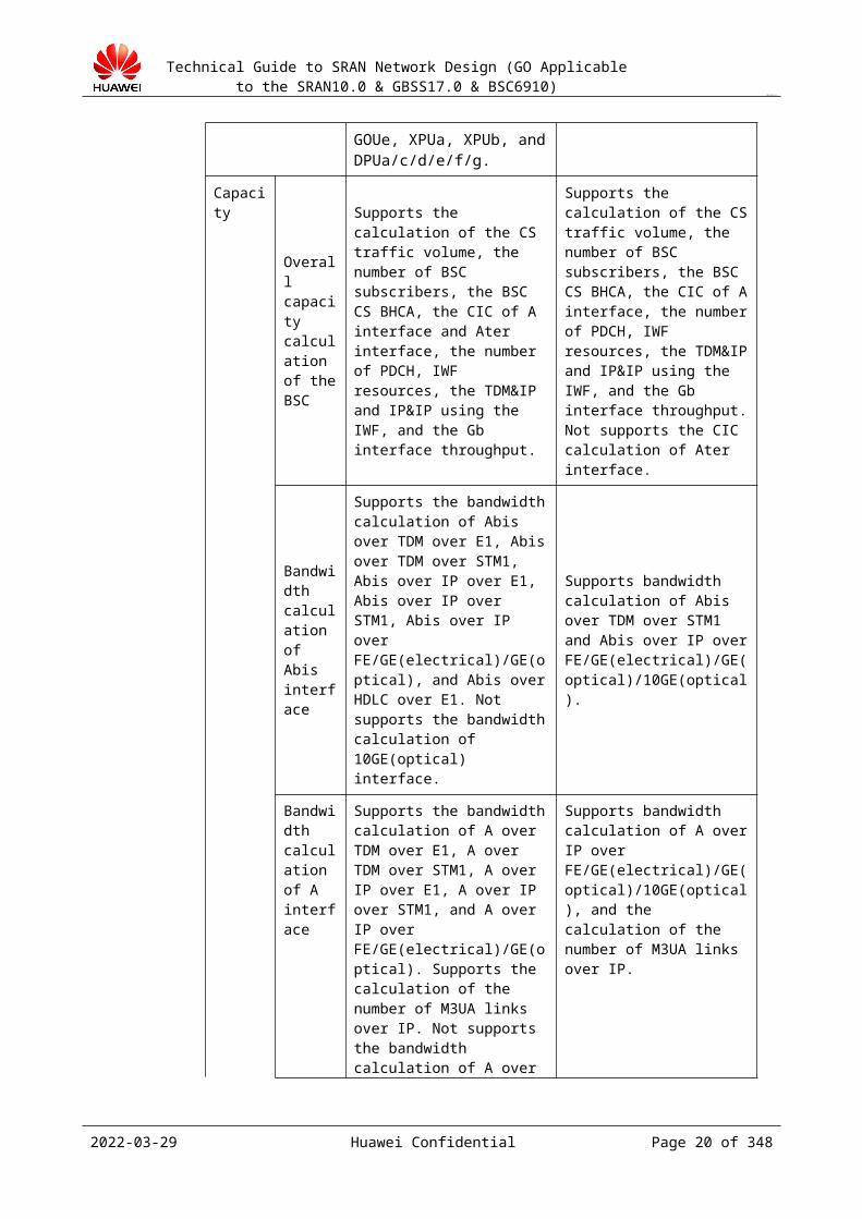
The following table lists the differences in network design between the GBSS17.0 BSC6900 and BSC6910:
Item BSC6900 BSC6910
Resource allocation
Not supports the EXOUa in 10 GE or EGPUa. Supports TDM exchange, TNU boards, EIUa, EIUb, OIUa, OIUb, FG2a, FG2c, FG2d, PEUa, PEUc, GOUa, GOUc, GOUd, GOUe, XPUa, XPUb, and DPUa/c/d/e/f/g.
Supports the EXOUa in 10 GE and EGPUa, FG2c, GOUc, POUc, GOUd, GOUe, and FG2d boards. Not supports TDM exchange, TNU boards, and TC subracks.
Capacity
Overall capacity calculation of the BSC
Supports the calculation of the CS traffic volume, the number of BSC subscribers, the BSC CS BHCA, the CIC of A interface and Ater interface, the number of PDCH, IWF resources, the TDM&IP and IP&IP using the IWF, and the Gb interface throughput.
Supports the calculation of the CS traffic volume, the number of BSC subscribers, the BSC CS BHCA, the CIC of A interface, the number of PDCH, IWF resources, the TDM&IP and IP&IP using the IWF, and the Gb interface throughput. Not supports the CIC calculation of Ater interface.
Bandwidth
Supports the bandwidth calculation of Abis over TDM
Supports bandwidth calculation of Abis over TDM over STM1
2023-04-22 Huawei Confidential Page 16 of 258
Technical Guide to SRAN Network Design (GO Applicable to the SRAN10.0 & GBSS17.0 & BSC6910)
CONFIDENTIAL
calculation of Abis interface
over E1, Abis over TDM over STM1, Abis over IP over E1, Abis over IP over STM1, Abis over IP over FE/GE(electrical)/GE(optical), and Abis over HDLC over E1. Not supports the bandwidth calculation of 10GE(optical) interface.
and Abis over IP over FE/GE(electrical)/GE(optical)/10GE(optical).
Bandwidth calculation of A interface
Supports the bandwidth calculation of A over TDM over E1, A over TDM over STM1, A over IP over E1, A over IP over STM1, and A over IP over FE/GE(electrical)/GE(optical). Supports the calculation of the number of M3UA links over IP. Not supports the bandwidth calculation of A over IP over 10 GE(optical).
Supports bandwidth calculation of A over IP over FE/GE(electrical)/GE(optical)/10GE(optical), and the calculation of the number of M3UA links over IP.
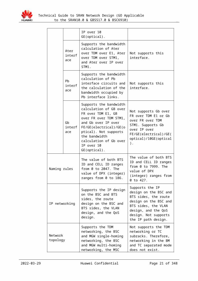
Ater interface
Supports the bandwidth calculation of Ater over TDM over E1, Ater over TDM over STM1, and Ater over IP over STM1.
Not supports this interface.
Pb interface
Supports the bandwidth calculation of Pb interface circuits and the calculation of the bandwidth occupied by Pb interface links.
Not supports this interface.
Gb interface
Supports the bandwidth calculation of GB over FR over TDM E1, GB over FR over TDM STM1, and Gb over IP over FE/GE(electrical)/GE(optical). Not supports the bandwidth calculation of Gb over IP over 10 GE(optical).
Not supports Gb over FR over TDM E1 or Gb over FR over TDM STM1. Supports Gb over IP over FE/GE(electrical)/GE(optical)/10GE(optical).
Naming rules
The value of both BTS ID and CELL ID ranges from 0 to 2047. The value of DPX (integer) ranges from 0 to 186.
The value of both BTS ID and CELL ID ranges from 0 to 7999. The value of DPX (integer) ranges from 0 to 427.
IP networking
Supports the IP design on the BSC and BTS sides, the route design on the BSC and BTS sides, the VLAN design, and the QoS design.
Supports the IP design on the BSC and BTS sides, the route design on the BSC and BTS sides, the VLAN design, and the QoS design. Not supports the IP path design.
2023-04-22 Huawei Confidential Page 17 of 258

Technical Guide to SRAN Network Design (GO Applicable to the SRAN10.0 & GBSS17.0 & BSC6910)
CONFIDENTIAL
Network topology
Supports the TDM networking, the BSC and MGW single-homing networking, the BSC and MGW multi-homing networking, the MSC Pool networking, the SGSN pool networking, all-IP networking, hybrid networking, and the transmission resource pool networking.
Not supports the TDM networking or TC subracks. Therefore, networking in the BM and TC separated mode does not exist. Supports the BSC and MGW single-homing networking, the BSC and MGW multi-homing networking, the MSC Pool networking, the SGSN pool networking, all-IP networking, hybrid networking, and the transmission resource pool networking.
Reliability
Supports the reliability design of active/standby port links, load-balancing, data configuration, multiple transmission channels, the VRRP in IP networking, the SCTP multi-homing, the BSC multi-homing MGWs, the MSC pool, the SGSN pool, the transmission resource pool over A interface, the OM, clock, and Ethernet link aggregation.
Supports the reliability design of active/standby port links, load-balancing, data configuration, multiple transmission channels, the VRRP in IP networking, the SCTP multi-homing, the BSC multi-homing MGWs, the MSC pool, the SGSN pool, the transmission resource pool over A interface, the OM, clock, and Ethernet link aggregation. Not supports the reliability design of the TC pool.
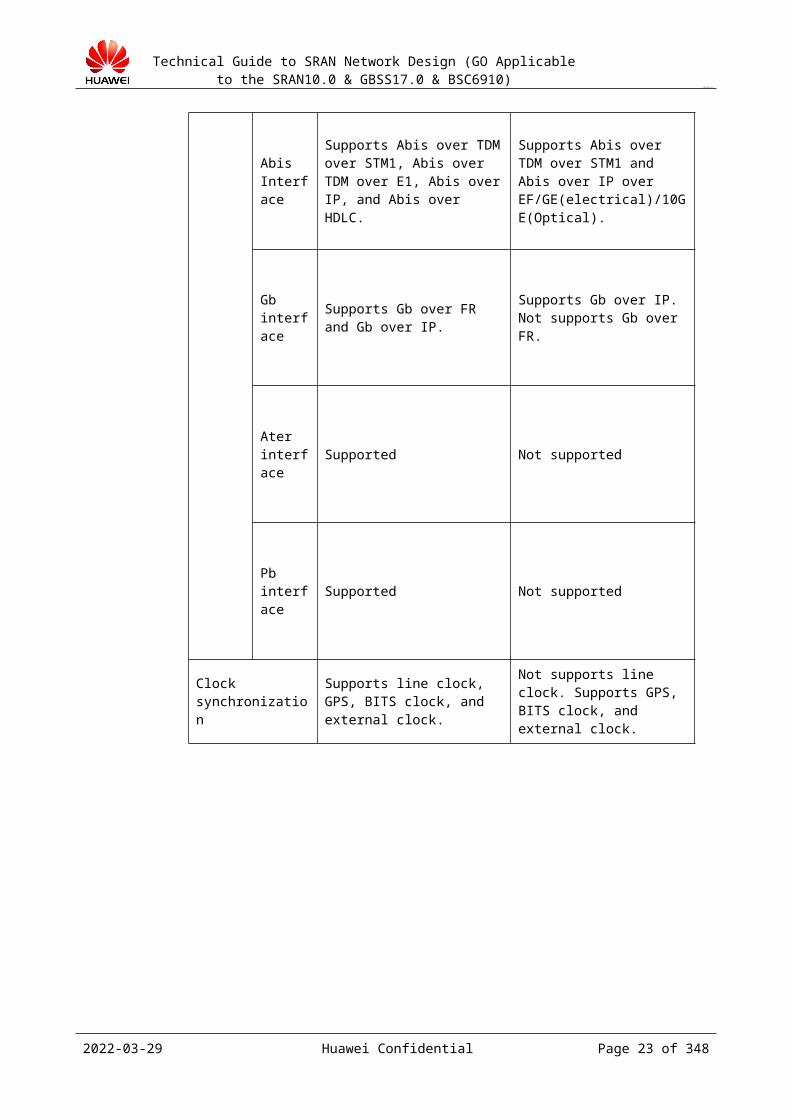
Transmission interface
A interface
Supports A over TDM, A over IP over FE/GE(electrical)/GE(optical), and A over IP over E1.
Not supports A over IP over E1. Supports A over IP over FE/GE(electrical)/GE(optical)/10GE(optical).
Abis Interface
Supports Abis over TDM over STM1, Abis over TDM over E1, Abis over IP, and Abis over HDLC.
Supports Abis over TDM over STM1 and Abis over IP over EF/GE(electrical)/10GE(Optical).
Gb interface
Supports Gb over FR and Gb over IP.
Supports Gb over IP. Not supports Gb over FR.
2023-04-22 Huawei Confidential Page 18 of 258

Technical Guide to SRAN Network Design (GO Applicable to the SRAN10.0 & GBSS17.0 & BSC6910)
CONFIDENTIAL
Ater interface Supported Not supported
Pb interface Supported Not supported
Clock synchronization
Supports line clock, GPS, BITS clock, and external clock.
Not supports line clock. Supports GPS, BITS clock, and external clock.
Foreword
1.1 ObjectivesThis document guides global system for mobile communications (GSM) base station subsystem (BSS) network design engineers through the network design and delivery of GSM BSS establishment, migration, expansion, and optimization. With the help of this document, a GSM BSS network design engineer can use high-level design (HLD) and low-level design (LLD) templates for GSM BSS network design to work out a final GSM BSS network design report for a customer.
A network design report consists of the HLD and LLD. The HLD provides the customer with the design of the network topology, networking, transmission, interfaces, resource capacity, function services, operation and maintenance (O&M), clock, and time synchronization. This document covers all the guidance principles. The LLD is intended for engineering guidance, and provides the design of the device board layout, cable connections, and key data configuration. You can use the network equipment planning (NEP) tool to generate the LLD.
2023-04-22 Huawei Confidential Page 19 of 258
Technical Guide to SRAN Network Design (GO Applicable to the SRAN10.0 & GBSS17.0 & BSC6910)
CONFIDENTIAL
1.2 ScopeThis document describes the design principles, design methods, and output formats of the BSS networking, transmission, interfaces, services, and O&M. The core network elements (NEs) involved in BSS network design are the base station controller (BSC), packet control unit (PCU), and BTS, and the involved interface NEs are the mobile switching center (MSC) server, media gateway (MGW), M2000, serving GPRS support node (SGSN), and local maintenance terminal (LMT).
1.3 ConstraintsThis document is developed based on GBSS17.0 BSC6910 and is applicable to the GSM Only mode of the BSC6910. Network design of the BSC6900 is described in Technical Guide to Single RAN Network Design V100R003 (GO applicable to SRAN10.0&GBSS17.0&BSC6910). The GU mode is described in the Single RAN network design guide.
1.4 Dependency Before the network design, you must collect the required data based on the information
collection template for network design. During the network design, you need to effectively communicate with the operator and core network engineers to ensure that the required information is accurate and the change causes and change results are recorded.
The network design personnel must be global technical service (GTS) engineers who are familiar with the BSC6910 and are engaged in engineering or maintenance for more than one year.
The network design guide is updated based on changes in the BSC and application scenarios and is available at http://support.huawei.com. You can obtain the latest version of the guide from the following path:Documentation > Wireless > Wireless Public > Wireless Professional Services Product > Technical Guides
2023-04-22 Huawei Confidential Page 20 of 258
Technical Guide to SRAN Network Design (GO Applicable to the SRAN10.0 & GBSS17.0 & BSC6910)
CONFIDENTIAL
2 Overview of Network Design
The BSS network design service is provided in the engineering preparation and delivery stage. The network planning (NP) provided by the network design department of Sales & Services, the network development planning provided by the operator, and the radio network plan provided by the network planner are the input of the HLD and LLD. The BSS network design guides the follow-up network deployment design and engineering.
Figure 2-1 shows the position of the BSS network design in the entire network construction process:
Figure 2-1 Position of the BSS network design in the entire network construction process
The GSM BSS network design service involves the overall designs of the networking, transmission, interfaces, resource capacity, functional services, O&M, and clock of the network. Focusing on the security, balance, and extensibility of the network, the GSM BSS network design provides guidance for engineering and construction and guarantees high-quality network operation for operators.
2023-04-22 Huawei Confidential Page 21 of 258

Technical Guide to SRAN Network Design (GO Applicable to the SRAN10.0 & GBSS17.0 & BSC6910)
CONFIDENTIAL
3 Overall Guidance Principles
Generally, the scale of GSM BSS network construction is large, numerous NEs are involved, and the interface interworking is complicated. The BSS network design principles are as follows:
Principle of area-based designThe BSS network design is implemented based on the network construction plan of the operator, areas, and stages in engineering. Generally, design is implemented in a "cake-cutting" manner with an MSC and all the BSCs mounted to the MSC as a cluster. In this way, the design work can be simplified, and the design process is lengthened so that the design workload can be distributed properly based on the engineering schedule.
Principle of interworkingThe BSS network design and core network design are closely related. Therefore, during the BSS network design, designers must effectively communicate with core network designers on issues, such as NE homing, interface interworking, and device capacity.
Principle of security in network designThe purpose of network design is to provide the customer with an available and reliable network that can handle burst traffic and can recover quickly in the event of network faults.
Principle of proper utilization of resourcesThe design principle of resources on a network varies with the development stage of the network. For example, if the number of users on a network rapidly increases, the resource usage cannot be designed too high. Otherwise, after the network is constructed, new BSCs may be required, and then the new BTSs result in hybrid networking and require re-homing, or new TRXs cannot be added for capacity expansion due to capacity limitation of the BSC after resources are used up.
Principle of interface independenceThe A, Gb, and Abis interfaces are physically independent. That is, a physical board can be configured with only one type of logical interfaces. Do not configure the A, Abis, and Gb interfaces on the same interface board because of the inconvenience for follow-up maintenance and expansion and the greater impact from board faults.
2023-04-22 Huawei Confidential Page 22 of 258
Technical Guide to SRAN Network Design (GO Applicable to the SRAN10.0 & GBSS17.0 & BSC6910)
CONFIDENTIAL
4 Overview of Key NEs
BSCThe BSC connects to the MSC and BTS through the A interface and Abis interface respectively. A PCU is embedded to implement radio resource management, BTS management, power control, handover control, radio network configuration, and radio network performance measurement.
BTSThe BTS/eGBTS connects to the BSC through the Abis interface and communicates with mobile stations (MSs) through the radio interface. The BTS/eGBTS provides radio functions in the BSS. For example, the BTS transmits and receives radio signals, measures the quality of the radio network, controls power, and implements channel coding, interleaving, and encrypting for radio channels.
PCUThe built-in PCU connects to the SGSN through the Gb interface. The PCU is introduced in the BSS so that the BSS supports the general packet radio service (GPRS) packet service. The PCU manages packet radio resources, controls packet calls, and transmits data packets on the radio interface and Gb interface
MSC serverThe MSC server provides switching functions and implements call switching between the public land mobile network (PLMN) and the public switched telephony network (PSTN). The MSC server provides telecom services, bearer services, and supplementary services for mobile subscribers.
SGSNThe SGSN is a core network device in the GSM packet switched (PS) domain. It implements functions, such as mobility management, session management, data packet routing and forwarding, charging, SMS, customized applications for mobile network enhanced logic (CAMEL), and quality of service (QoS) management.
2023-04-22 Huawei Confidential Page 23 of 258
Technical Guide to SRAN Network Design (GO Applicable to the SRAN10.0 & GBSS17.0 & BSC6910)
CONFIDENTIAL
5 Overview of the Network Design Tool
The NEP tool is developed to improve the efficiency of network design delivery. This tool can complete most network designs automatically. If you use the NEP tool in network design, the efficiency can be greatly improved. For detailed information, contact Li Yongqing (employee ID: 00141602), network design delivery representative of Network Integration Service (NIS).
2023-04-22 Huawei Confidential Page 24 of 258
Technical Guide to SRAN Network Design (GO Applicable to the SRAN10.0 & GBSS17.0 & BSC6910)
CONFIDENTIAL
6 Important Reference Document
The Transmission Configuration Specifications describes the specifications of IP planning, QoS parameters, and VLAN planning used for IP transmission. Related links are available at http://support.huawei.com:
A&GB Interface Configuration Specification_IP(GBSS17.0)Wireless > Wireless Public > Wireless Professional Services Product > Technical Guideshttp://support.huawei.com/support/pages/navigation/gotoKBNavi.do?actionFlag=getAllJsonData&colID=ROOTWEB|CO0000000064&level=4&itemId=203-00051453&itemId0=29-7&itemId1=3-154&itemId2=1-632&itemId3=202-00051452&itemId4=203-00051453&itemId5=&itemId6=&itemId7=&itemId8=&itemId9=&materialType=123-2&isHedexDocType=&pageSize=20
2023-04-22 Huawei Confidential Page 25 of 258

Technical Guide to SRAN Network Design (GO Applicable to the SRAN10.0 & GBSS17.0 & BSC6910)
CONFIDENTIAL
7 Product Specifications
The specifications vary with the product version. For details about the capacity specifications of the BSC of a certain version, see the officially released documents of that version.Specifications and capacity configuration of the BSC must be based on a certain traffic model, all contracts must be established on a given traffic model to ensure the accuracy of the contract. If you are unable to obtain accurate traffic.
7.1 BSC SpecificationsFor details about BSC specifications, see BSC6910 GU Product Description in the Hedex BSC6910 GU product documentation.
Specifications of a BSC adopting an all-IP network change as follows: The number of TRXs increases from 8192 in the BSC6900 to 24000 in the BSC6910.
7.1.1 Hardware CapacityTable 7-1 lists the typical maximum configuration of R16 boards in BSC6910 GSM. The GBSS17.0 BSC6910 has a maximum configuration of one cabinet and three subracks in the GO mode and supports A over TDM, but it cannot be configured in BM/TC separated mode. The GBSS15.0 does not support A over TDM.
Table 7-1 Typical maximum configuration of R16 boards in BSC6910 GSM (Abis over TDM and A over IP are adopted.)
Specification and Subrack Name 1 MPS+2 EPS
Number of cabinets 1
Maximum BHCA (M) 15
Traffic volume (Erlang) 43750
Number of TRXs 7000
Number of PDCHs that can be activated (MCS-9) 28000
2023-04-22 Huawei Confidential Page 26 of 258

Technical Guide to SRAN Network Design (GO Applicable to the SRAN10.0 & GBSS17.0 & BSC6910)
CONFIDENTIAL
Gb throughput (G) 2.688
Table 7-2 lists the typical maximum configuration of traffic volume of R16 boards in BSC6900 GSM where the BM and TC are separated.
Table 7-2 Typical maximum configuration traffic volume of R16 boards in BSC6900 GSM (all-IP mode used)
Specification and Subrack Name 1 MPS+2 EPS (Number of Subracks Can Be Changed)
Number of cabinets 1
Maximum BHCA (M) 52
Traffic volume (Erlang) 150000
Number of TRXs 24000
Number of PDCHs that can be activated (MCS-9) 96000
Gb throughput (G) 8
7.1.2 Estimation of BSC Configuration CapacityBSC configuration capacity is estimated based on two key BSC counters: Busy Hour Call Attempts (BHCA) and traffic volume. The actual configuration capacity is related to the number of interface boards and the number of service processing boards and is the minimum capacity calculated based on each board. The estimation of the configuration capacity conducted currently, however, is based on the number of EGPUa(GCUP) boards. This section describes a simple method for estimating BSC configuration capacity based on the number of EGPUa(GCUP) boards.
The following describes how to calculate the maximum number of BHCA and maximum traffic volume:
The method for calculating the maximum number of BHCA allowed by the current configuration is as follows:− If all interfaces adopt the IP transmission mode, the maximum number of BHCA
allowed by the current configuration is calculated as follows: Maximum number of BHCA = MIN ((Number of EGPUa(GCUP) pairs on the current BSC x Number of BHCA supported by a pair of EGPUa(GCUP)s x 80%, 52,000,000)
− If all Abis interfaces adopt the TDM transmission mode, the maximum number of BHCA allowed by the current configuration is calculated as follows: Maximum number of BHCA = MIN ((Number of EGPUa(GCUP) pairs on the current BSC x Number of BHCA supported by a pair of EGPUa(GCUP)s x 80%, 21,000,000)
− If the Abis interfaces adopt the TDM/IP hybrid transmission mode, the maximum number of BHCA allowed by the current configuration is calculated as follows: Maximum number of BHCA = MIN ((Number of EGPUa(GCUP) pairs on the
2023-04-22 Huawei Confidential Page 27 of 258

Technical Guide to SRAN Network Design (GO Applicable to the SRAN10.0 & GBSS17.0 & BSC6910)
CONFIDENTIAL
current BSC x Number of BHCA supported by a pair of EGPUa(GCUP)s x 80%, 52,000,000)
The simplified method for calculating traffic (expressed in Erlang) is as follows:− If all interfaces adopt the IP transmission mode, the maximum traffic volume allowed
by the current configuration is calculated as follows: Maximum traffic volume = MIN ((Number of EGPUa(GCUP) pairs on the current BSC x Traffic volume supported by a pair of EGPUa(GCUP)s, 150,000)
− If all Abis interfaces adopt the TDM transmission mode, the maximum traffic volume allowed by the current configuration is calculated as follows: Maximum traffic volume = MIN ((Number of EGPUa(GCUP) pairs on the current BSC x Traffic volume supported by a pair of EGPUa(GCUP)s, 62,500)
− If the Abis interfaces adopt the TDM/IP hybrid transmission mode, the maximum traffic volume allowed by the current configuration is calculated as follows: Maximum traffic volume = MIN ((Number of EGPUa(GCUP) pairs on the current BSC x Traffic volume supported by a pair of EGPUa(GCUP)s, 150,000)
7.2 Board Specifications7.2.1 BSC6910 Board Specifications
For details about board specifications, see Boards in BSC6910 GSM Hardware Description in the BSC6910 documentation package. This document is officially issued to customers.
Hardware Version
Involved Board
HW6910 R15
SCUb、GCGa、GCUa、GCUb、GCGb、FG2c、GOUc、EGPUa、EXOUa、EOMUa、ESAUa、ENIUa、EXPUa
HW6910 R16
SCUb、GCUb、GCGb、FG2c、GOUc、EGPUa、EXOUa、EOMUa、ESAUa、ENIUa、GOUe、EXPUa
HW6910 R17
SCUb、FG2c、EGPUa、EXOUa、EOMUa、ESAUa、ENIUa, SPUc 、GCGb、GCUb、GOUe、EXPUa
In the BSC6910, only the POUc boards support Abis over TDM and A over TDM. The POUc supports 1024 TRXs (without extra license control). In the BSC6900, the POUc supports 512 TRXs and can be used in the BSC6910. In the BSC6910, POUc boards support TDM and IP over E1 transmission.
In A over TDM transmission mode, DPUf boards must be configured to process user-plane CS data. The number of configured DPUf boards is determined according to the number of CICs. The DPUf supports N+1 backup mode.
Number of Configured DPUf = RoundUp(MaxACICPerBSCTDM/ TCNoPerDPUf,0)
where
2023-04-22 Huawei Confidential Page 28 of 258
Technical Guide to SRAN Network Design (GO Applicable to the SRAN10.0 & GBSS17.0 & BSC6910)
CONFIDENTIAL
MaxACICPerBSCTDM indicates the maximum number of required A CICs on a BSC and is calculated based on the traffic model.
7.2.2 Service Processing ModulesTable 7-1 lists the specifications of service processing boards.
Table 7-1 Specifications of service processing boards
Board
Logical Function
Full Name of Logical Function
Description
Specifications
Condition
EGPUa
RMP Resource management processing
Resource management processing
This board is for resource management of the system.
A BSC is configured with a pair of EGPUa boards.
GCUP GSM BSC control plane and user plane processing
This board (GCUP) processes services of control plane and user plane integration. In addition, it supports CS and PS services of the standard TRX.
This board processes services of control plane and user plane integration. The specification is: 1000 TRXs600 BTSs600 CELLs3000 PDCHs.
The BHCA is based on Huawei default traffic model.
GMCP GSM BSC mathematics calculation processing
If the board is used for GSM BSC mathematics calculation processing, it can calculate using the Interference Based Channel Allocation (IBCA) algorithm.
None The GMCP needs to be configured if the IBCA feature is enabled.
2023-04-22 Huawei Confidential Page 29 of 258
Technical Guide to SRAN Network Design (GO Applicable to the SRAN10.0 & GBSS17.0 & BSC6910)
CONFIDENTIAL
NASP Network assisted service process
Network assisted service processing unit
None The NASP needs to be configured if Intelligent Wi-Fi Detection and Selection is enabled.
EXPUa
RMP Resource management processing
Resource management processing board.
This board is for resource management of the system.
A BSC is configured with a pair of EXPUa boards.
GCUP GSM BSC control plane and user plane processing
This board (GCUP) processes services of control plane and user plane integration. In addition, it supports CS and PS services of the standard TRX.
This board processes services of control plane and user plane integration. The specification is: 1000 TRXs600 BTSs600 CELLs3000 PDCHs.
The BHCA is based on Huawei default traffic model.
GMCP GSM BSC mathematics calculation processing
If the board is used for GSM BSC mathematics calculation processing, it can calculate using the IBCA algorithm
None The GMCP needs to be configured if the IBCA feature is enabled.
ENIUa NIU Evolved network intelligence unit
Evolved network intelligence unit
An ENIUa board has a capacity of 8000 M PS throughput in the RAN15.0.
The ENIUa needs to be configured if the Evolved Deep Packet Inspection function is enabled.
2023-04-22 Huawei Confidential Page 30 of 258
Technical Guide to SRAN Network Design (GO Applicable to the SRAN10.0 & GBSS17.0 & BSC6910)
CONFIDENTIAL
ESAUa
SAU Evolved service aware unit
Evolved service aware unit
The SAU board is for collecting, filtering, and gathering data of the service board, and periodically sending it to Nastar.
The SAU needs to be configured on the BSC, if a user purchases Nastar. A BSC is configured with only one ESAUa board.
DPUf DPU CS Data Processing Unit (1920 CICs)
This board provides the TC function to process CS data and works in N+1 backup mode.
This board provides the TC function (supporting 1920 CICs) in A over TDM mode.
If common AMR is used, the DPUf supports 1920 CICs. If WB AMR is used, the number of supported CICs is halved. That is, the board capability required by WB AMR calls is two times greater than that required by common calls.
7.2.3 Interface ModulesTable 7-1 lists the interfaces applicable to the boards.
Table 7-1 Interfaces applicable to the boards
Board Name Description Applicable Interface
FG2c IP Interface Unit (12 FE/4 GE, Electric)
IP: A/Abis/Lb/Gb/Iur-g
GOUc IP Interface Unit(4 GE, Optical)
IP: A/Abis/Lb/Gb/Iur-g
EXOUa Evolved 10GE Optical interface Unit
IP: A/Abis/Lb/Gb/Iur-g
POUc TDM Interface Unit(4 STM-1, channelized)
TDM: Abis
Table 7-2 lists the specifications of interface boards over different interfaces.
2023-04-22 Huawei Confidential Page 31 of 258
Technical Guide to SRAN Network Design (GO Applicable to the SRAN10.0 & GBSS17.0 & BSC6910)
CONFIDENTIAL
Table 7-2 Specifications of interface boards over different interfaces
Model Transmission Mode
Port Type
Port No.
TRX A CIC (64 kbit/s)
Ater CIC (16 kbit/s)
Gb Throughput(Mbit/s)
WP1D000FG201 (FG2c)
IP FE/GE electrical port
12/4 2048 23040 N/A 2000
WP1D000GOU01 (GOUc)
IP GE optical port
4 2048 23040 N/A 2000
QM1D00EXOU00 (EXOUa)
IP 10 GE optical port
2 8000 75000 N/A 8000
WP1D000GOU03 (GOUe)
IP GE optical port
4 2048 23040 N/A 2000
WP1D000POU01 (POUc)
TDM CSTM-1 port
4 1024 7680 N/A 488
IP IP CSTM-1 4 2048 N/A N/A N/A
The total number of required interface boards is the sum of interface boards over all interfaces. Interface boards work in 1+1 backup mode. The BSC does not support BM/TC separated mode and is not configured with the Ater interface. The A, Gb, and Abis interfaces must be configured on the BM subrack side. On a GSM network, it is not recommended that the A, Abis, and Gb share an interface board. Interface boards are configured over different interfaces.
Calculation of the number of Abis interface boards
Select appropriate transmission ports based on the network plan. Calculate the number of required Abis interface boards based on the service capability (TRX support capability) and port requirements, and then select the maximum value.
Number of Abis interface boards = 2 x RoundUp(MAX(Number of TRXs in the transmission mode/Number of TRXs supported by the interface board, number of ports in the transmission mode/number of ports supported by the interface board),0)
When configuring Abis interface boards, concern the following aspects:
2. In Abis over TDM transmission mode, the BSC6910 only supports the POUc and does not support the TDM over E1/T1 interface board. If the Abis uses TDM over E1/T1 transmission on the BSC side, optical or electrical switching devices, such as Huawei OSN device, are required to perform switching between E1/T1 and STM-1.
3. The BSC6910 cannot be configured with a 10GE EXOUa interface board. Instead, it can only be configured with the FG2 or GOUc working as the GE interface board when both of the following conditions are met:− The BTS uses IP over E1 transmission.− The BSC uses IP transmission.
2023-04-22 Huawei Confidential Page 32 of 258

Technical Guide to SRAN Network Design (GO Applicable to the SRAN10.0 & GBSS17.0 & BSC6910)
CONFIDENTIAL
4. Only the POUc board of the BSC6910 supports IP over E1 transmission. Calculation of the number of A interface boards
Select appropriate transmission ports based on the network plan. Calculate the number of required A interface boards based on the service capability (CIC support capability).Number of A interface boards = 2 x RoundUp(A CIC Number/Support capability of the A interface board,0)
When configuring A interface boards, concern the following aspects:
In A over TDM transmission mode, the BSC6910 only supports the POUc interface board (TDM over STM-1) and does not support the TDM over E1/T1 interface board. If the Abis uses incoming TDM over E1/T1 transmission, optical or electrical switching devices, such as Huawei OSN device, are required to perform switching between E1/T1 and STM-1.
Calculation of the number of Gb interface boardsSelect appropriate transmission ports based on the network plan. Calculate the number of required Gb interface boards based on the service capability (bandwidth support capability).Number of Gb interface boards = 2 x RoundUp(Gb throughput/Support capability of the Gb interface board,0)
Calculation of the total number of required interface boardsThe total number of required interface boards is calculated as follows:Total number of interface boards = Number of Abis interface boards + Number of A interface boards + Number of Gb interface boards
2023-04-22 Huawei Confidential Page 33 of 258
Technical Guide to SRAN Network Design (GO Applicable to the SRAN10.0 & GBSS17.0 & BSC6910)
CONFIDENTIAL
8 BOQ Review Guide
8.1 Design Overview8.1.1 Purpose of the Design
Review the pre-sales bill of quantities (BOQ) configuration based on accurate network planning information to ensure that the BOQ meets network construction requirements.
8.1.2 Input of the Design Device BOQ Network planning information (obtain the information, including the BSC coverage,
traffic, location area code (LAC) partitioning, and BTS homing from the on-site network planning department.)
Information about the equipment room, power supply, or transmission of the customer, and special requirements of the customer
8.1.3 Contents of the Design BOQ review result Defects in the BOQ and solution (suggestions)
8.1.4 Design ReferenceGSM BSC Configuration Manual
8.2 Overview of Pre-sales Network DesignThis section describes the pre-sales network planning and design as well as BOQ principles and process to guide network design personnel through BOQ review.
In the network deployment scenario, the pre-sales network design procedures are as follows:
1. The pre-sales network planner plans the number of TRXs and the number of BTSs in the areas based on the capacity, coverage, and information, such as coverage, predicted number of subscribers, and traffic per subscriber, provided by the customer.
2023-04-22 Huawei Confidential Page 34 of 258
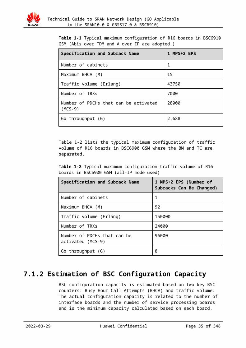
Technical Guide to SRAN Network Design (GO Applicable to the SRAN10.0 & GBSS17.0 & BSC6910)
CONFIDENTIAL
2. The pre-sales network designer confirms the BSC locations and network topology based on the transmission conditions, equipment room resources, and core network of the customer.
3. The pre-sales network designer uses the design tool to calculate the subrack and board BOQ configuration of each BSC based on the number of TRXs of each BSC, number of BTSs, half-rate ratio, transmission type, and number of BSCs.
In the network expansion scenario, the pre-sales network design procedures are as follows:
1. The pre-sales network planner plans the number of sites and carriers to be added based on the congestion rate, coverage, and frequency planning of the live network.
2. The pre-sales network designer calculates the number of pieces of BSC hardware required based on the number of sites, number of TRXs, half-rate ratio, and transmission type, deducts the number of pieces of existing hardware from the number of pieces of BSC hardware required to obtain the number of pieces of hardware to be added, and then generates the BSC device BOQ.
The pre-sales planning of the core network is different from that of the BSS. The BOQ and interface bandwidth data of the core network are obtained directly based on the number of subscribers, traffic per subscriber, and certain redundancy. Therefore, interface bandwidth inconsistency may occur. Generally, the calculation result of the core network is smaller, and this causes the interface bandwidth inconsistency. The BSS planning does not involve bandwidth bottleneck and facilitates follow-up network development.
8.3 BOQ Review PrinciplesUse the GSM NEP tool for BOQ review.
In BOQ review, the number of pre-sales configured boards, especially the number of Abis interface boards, is reviewed. If spare BOQ hardware is configured, the review is successful. If the BOQ hardware is insufficient, check with marketing personnel whether to change the delivery.
In the new network construction and migration scenarios, use the GSM NEP tool to calculate the required BSC hardware based on the number of BTSs, number of TRXs, and traffic model, and check the requirements against the pre-sales BOQ.
In the expansion scenario, use the GSM NEP tool to calculate the required BSC hardware based on the number of BTSs, number of TRXs, and traffic model after expansion, deduct the existing BSC hardware to obtain the number of pieces of hardware to be added, and check the number against the pre-sales expansion BOQ.
To meet the special requirements of some operators, the actual number of pieces of hardware in BOQ delivery is far greater than the actual required number of pieces of hardware. In terms of BTS distribution, the following principles are recommended (you communicate with the operator to learn the follow-up expansion plan):
BTSs are evenly distributed to subracks and Abis interface boards based on a certain redundancy ratio. This facilitates follow-up TRX expansion or BTS addition.
Traffic model parameters
The following content is quoted from the GBSS15.0 BSC6910 system capacity calculation manual. Ensure that the following content is for internal use only.
2023-04-22 Huawei Confidential Page 35 of 258

Technical Guide to SRAN Network Design (GO Applicable to the SRAN10.0 & GBSS17.0 & BSC6910)
CONFIDENTIAL
In this document, parameters are described in tables. Different colors in tables convey different meanings as follows:
Parameter Title
TRX Number
Parameter name
0.02 It is an input parameter, which is entered based on the network planning and design result. You can use the default value (if available) of an input parameter if the entered value cannot be obtained. The calculation result based on the default value is different from the actual situation. Generally, the result calculated based on the default value is larger. That is, more device resources are required.
300 It is an advanced parameter. You can enter a value or directly use the default value.
98% Automatically calculated result. Do not change this value unless you are absolutely confident of the new value. If you can provide the dimension result, you can use it, but you must ensure that the modification is correct.
8.4 CS Traffic ModelsThe circuit switched (CS) traffic model affects the BSC system capacity in the following aspects:
CS traffic on the control plane in the system. It is measured by the BHCA. If the traffic on the air interface in the system is specified, the traffic model affects the BHCA traffic on the control plane in the system.
CS traffic on the user plane in the system. It is measured in Erlang. If the number of subscribers on the network is specified, the traffic model affects the traffic on the user plane in the system.
Table 8-1 CS traffic model parameters
Parameter Name Default Value
Description
Average voice traffic per subscriber@BH(Erlang)
CSErlPerSub 0.02 Average busy-hour CS traffic per subscriber
Average Call Duration(Second)
CSCallDuration 60 Average busy-hour conversation duration per subscriber
Percent of Mobile originated calls
CSMOCRatio 50% Average busy-hour MOC ratio
Percent of Mobile terminated calls
CSMTCRatio 50% Average busy-hour MTC ratio
2023-04-22 Huawei Confidential Page 36 of 258
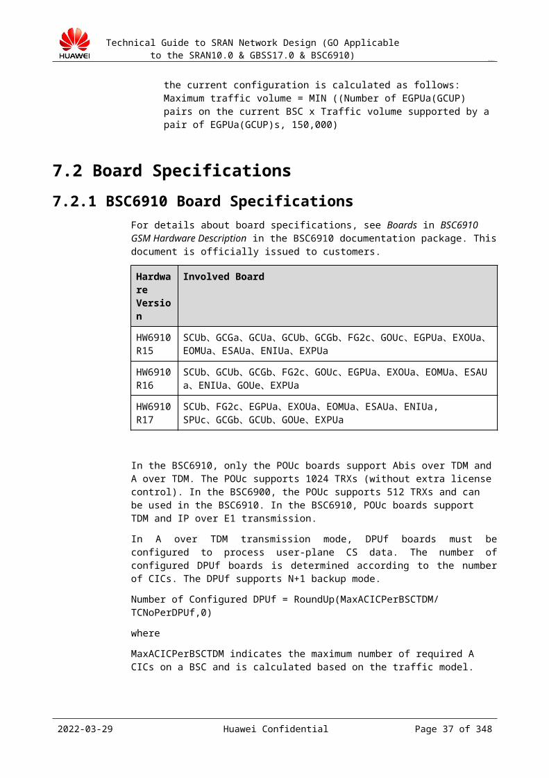
Technical Guide to SRAN Network Design (GO Applicable to the SRAN10.0 & GBSS17.0 & BSC6910)
CONFIDENTIAL
Parameter Name Default Value
Description
Average LUs/sub/BH CSLUPerSubinBH 1.2 Number of busy-hour location updates per subscriber
Average IMSI Attach/sub/BH
CSAttachPerSubinBH 0.15 Average busy-hour IMSI attachments per subscriber
Average IMSI Detach/sub/BH
CSDetachPerSubinBH 0.15 Average busy-hour IMSI detachments per subscriber
Average MO-SMSs /sub/BH
CSMOSMSPerSubinBH
0.6 Average busy-hour sent SMSs per subscriber
Average MT-SMSs /sub/BH
CSMTSMSPerSubinBH
1 Average busy-hour received SMSs per subscriber
Average intra-BSC HOs /sub/BH
CSIntraHOPerSubinBH
1.1 Average busy-hour intra-BSC handovers per subscriber
Average inter-BSC HOs /sub/BH
CSInterHOPerSubinBH
0.1 Average busy-hour inter-BSC handovers per subscriber
Paging Retransfer Ratio PagingRetransferRatio 35% Ratio of paging retries on the A interface in busy hours
Table 8-2 CS signaling load parameters
Parameter Name Default Value
Description
64k SS7 signaling links load
64kSS7SigLinkLoad 0.2 Busy-hour 64K signaling load
2M SS7 signaling links load
2MSS7SigLinkLoad 0.2 Busy-hour 2M signaling load
Table 8-3 GoS-related parameters
Parameter Name Default Value
Description
Grade of Service (GoS) on Um interface
UmBlockRatio 0.02 Um interface block ratio
Grade of Service (GoS) on A interface
ABlockRatio 0.001 Device block ratio
2023-04-22 Huawei Confidential Page 37 of 258
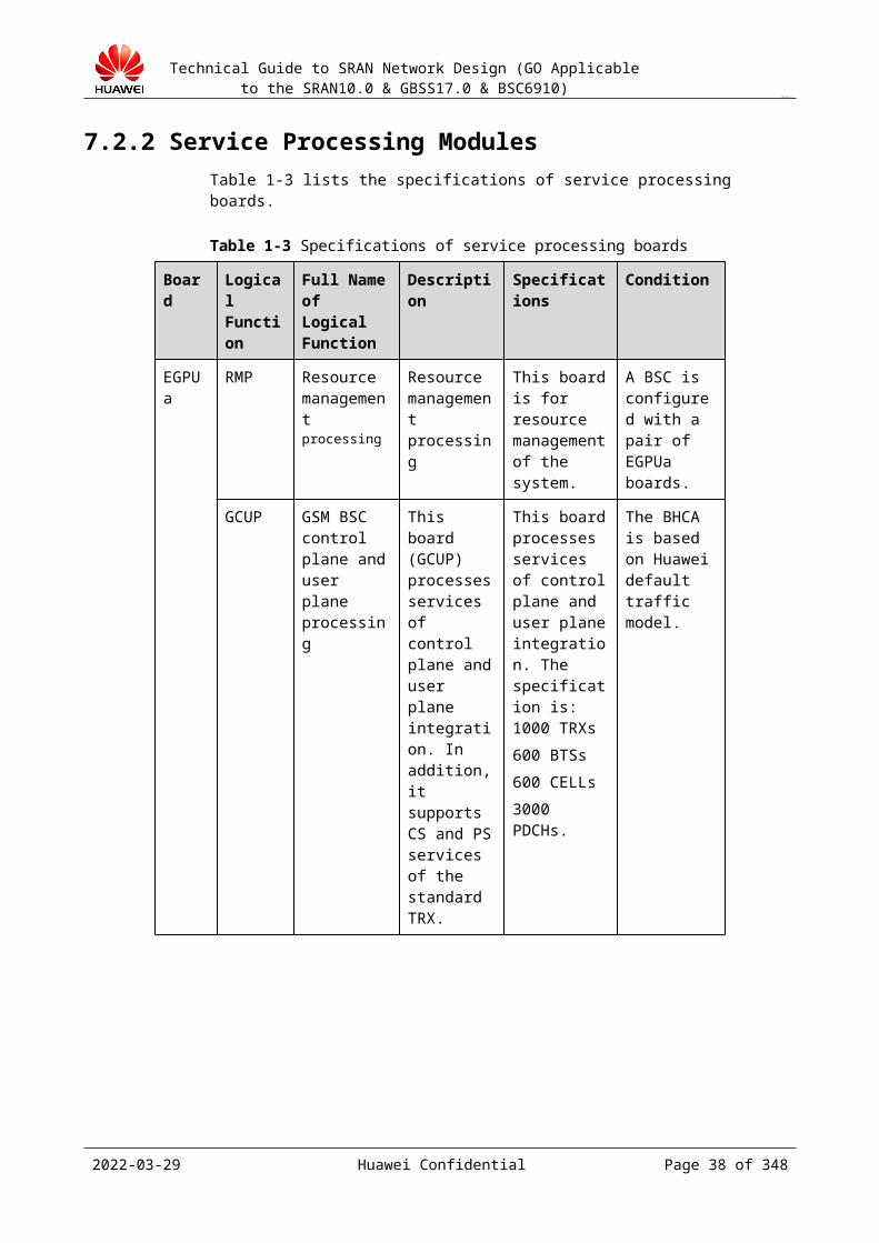
Technical Guide to SRAN Network Design (GO Applicable to the SRAN10.0 & GBSS17.0 & BSC6910)
CONFIDENTIAL
Table 8-4 Other related parameters
Parameter Name Default Value
Description
Average MOCs/sub/BH CSMOCPerSubinBH 0.6 Number of busy-hour calling times per subscriber = CSErlPerSub x 3600/CSCallDuration x CSMOCRatio
Average MTCs/sub/BH CSMTCPerSubinBH 0.6 Number of busy-hour called times per subscriber = CSErlPerSub x 3600/CSCallDuration x CSMTCRatio
MR report/sub/BH CSMRPerSubinBH 144 Average number of MRs reported by each subscriber in busy hours. Its weight in BHCA is zero. It is used only for reference.
Paging retransfer /sub/BH
CSRetransferPagingPerSubinBH
0.56 Average number of paging retransmission times per subscriber in busy hours on the A interface.
Parameter relationship in the CS traffic model
2. Relationship between CSMTCRatio and CSMOCRatio:CSMTCRatio = 1 – CSMOCRatio
3. Relationship between CSErlPerSub, CSCallDuration, CSMOCPerSubinBH, CSMOCPerSubinBH, and CSMTCPerSubinBH:CSMOCPerSubinBH = (CSErlPerSub x 3600/CSCallDuration) x CSMOCRatioCSMTCPerSubinBH = (CSErlPerSub x 3600/CSCallDuration) x CSMTCRatio
4. Calculation of CSMRPerSubinBH:CSMRPerSubinBH = (CSMTCPerSubinBH + CSMOCPerSubinBH) x CSCallDuration x 2
In the preceding formula, the MRs that are not reported in the call stage. For example, the MRs reported in the short message service (SMS) and signaling connection stages, are not included.
5. Relationship between CSRetransferPagingPerSubinBH and PagingRetransferRatio:CSRetransferPagingPerSubinBH = (CSMTCPerSubinBH + CSMTSMSPerSubinBH) x PagingRetransferRatio
2023-04-22 Huawei Confidential Page 38 of 258

Technical Guide to SRAN Network Design (GO Applicable to the SRAN10.0 & GBSS17.0 & BSC6910)
CONFIDENTIAL
8.5 PS Traffic ModelsThe packet switched (PS) traffic model affects the BSC system capacity in the following aspects:
If the number of subscribers in the system is specified, the PS traffic model determines the total traffic of PS services in the BSC.
The PS traffic model consists of the following:
Basic PS traffic model (This model is new in the R13. In R12 and earlier versions, only the PS user model is available.)
PS user model (For details about this model, see Table 8-2.)
Table 8-1 Basic PS traffic model
Parameter Name Value Description
Uplink TBF Est & Rel / Second/TRX
TBFUpPerSecPerTRX
1.75
It indicates the average number of uplink TBFs per second for each TRX in peak hours. Its default value is 1.75 for common networks and is 3.5 for PS networks with heavy traffic.
Downlink TBD Est & Rel / Second/TRX
TBFDownPerSecPerTRX 0.9
It indicates the average number of downlink TBFs per second for each TRX in peak hours. Its default value is 0.9 for common networks and is 1.8 for PS networks with heavy traffic.
PS Paging / Sub/BH PSPagingPerSub
1.25
It indicates the number of received peak-hour pagings for each PS subscriber. Its default value is 1.25 for common networks and is 2.5 for PS networks with heavy traffic.
Table 8-2 PS user model
Parameter Name Value
Description
GPRS Active Sub PSSubAct 10000 Number of online GPRS/EGPRS subscribers
average traffic per sub in busy hour (bit/s)
PSTrafficPerSubinBH 300 Average GPRS/EGPRS traffic per online subscriber in busy hours (application layer)
PS Traffic Peak Ratio PSPeakRatio 25% Ratio of the difference between the PS peak traffic and the average traffic to the average traffic. Do not use this parameter if it is not required.
2023-04-22 Huawei Confidential Page 39 of 258
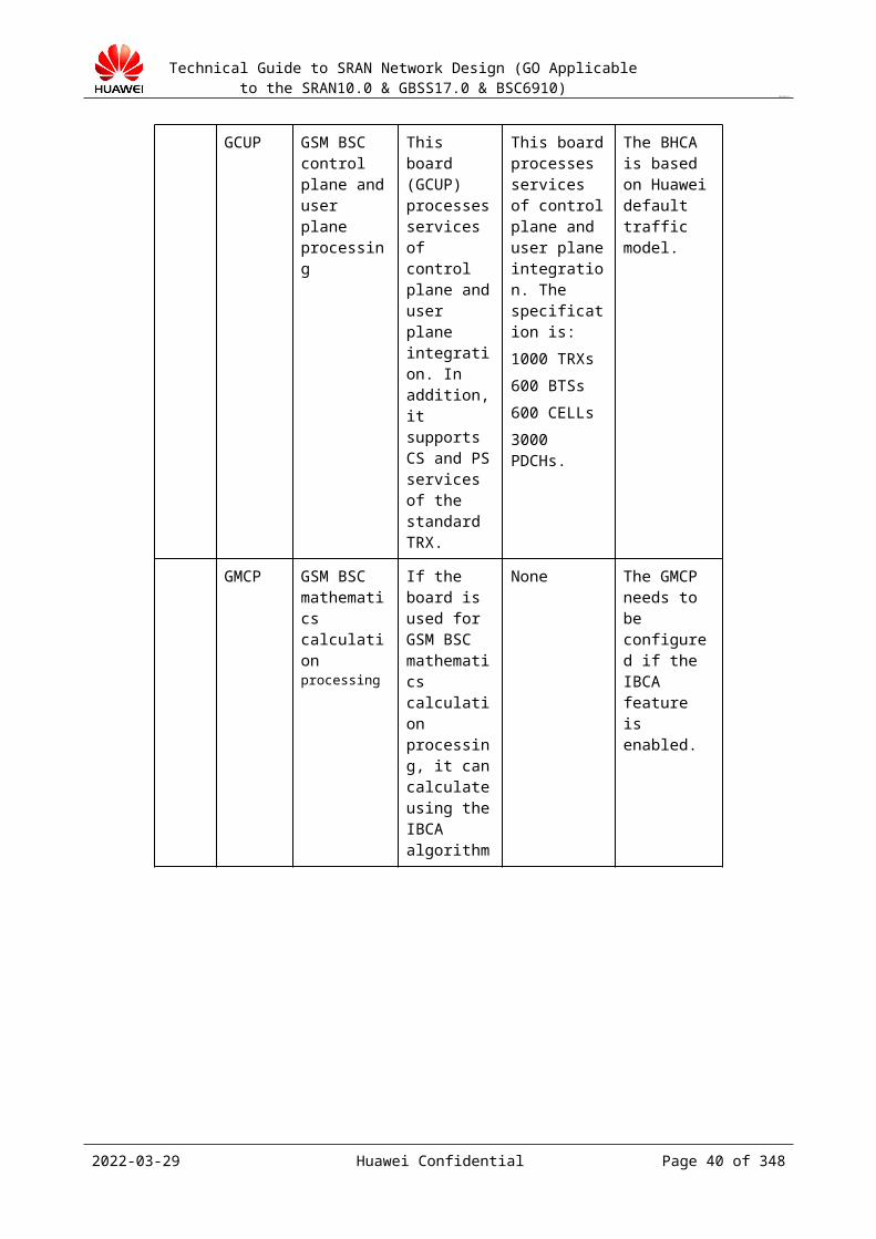
Technical Guide to SRAN Network Design (GO Applicable to the SRAN10.0 & GBSS17.0 & BSC6910)
CONFIDENTIAL
average IP packet data length in Gb (Bytes)
PayloadLenGb 300 Average packet length on the Gb interface. Do not use this parameter if it is not required.
Table 8-3 PS coding ratio and average rate
code scheme RatioCS1 0%
CS2 0%
CS3 0%
CS4 0%
MCS1 0%
MCS2 0%
MCS3 0%
MCS4 0%
MCS5 0%
MCS6 100%
MCS7 0%
MCS8 0%
MCS9 0%
The sum of the preceding coding rate ratios must be 100%.
Generally, the customer cannot provide the ratios of coding rates during calculation. You can use the customer-expected average rate to replace the inputs. For example, the customer-expected average rate is about 30 kbit/s. According to the preceding table, this average rate is within the rate range of the MCS6 coding mode. In this case, you can simply enter 100% as the ratio of the MCS6 coding mode.
8.6 Relationship Between Traffic Model and Traffic Statistics
Traffic model indicates the average number of typical subscriber behaviors for a subscriber. The total number of these subscriber behaviors can be obtained from the traffic statistics. The traffic model for a subscriber equals the total number divided by the number of subscribers.
The number of subscribers (SubPerBSC) served by a BSC must be available and accurate in the calculation of the traffic model.
Table 8-1 lists the performance counters corresponding to basic procedures.
2023-04-22 Huawei Confidential Page 40 of 258
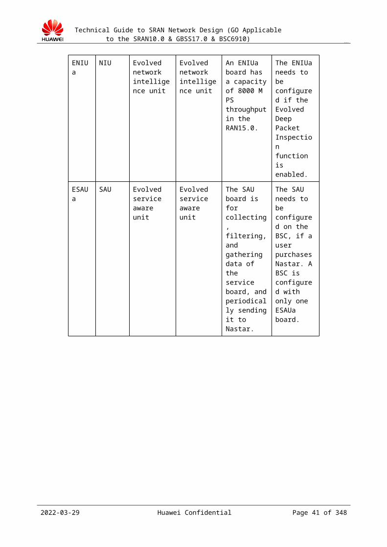
Technical Guide to SRAN Network Design (GO Applicable to the SRAN10.0 & GBSS17.0 & BSC6910)
CONFIDENTIAL
Table 8-1 Performance counters corresponding to basic procedures
Basic Procedure (Subscriber Operation)
Performance Counters (Sum of Cell Performance)
CS LUs (Location Update)
A300F: Channel Requests (Location Updating)
Average IMSI Attachs (IMSI Attachs)
From MSC
Average IMSI Detachs (IMSI Detachs)
From MSC
CS calls A300A: Channel Requests (MOC) + A300C: Channel Requests (MTC) – CA334A: Total Uplink Point-to-Point Short Messages – CA334B: Total Downlink Point-to-Point Short Messages
MR Reports S329: Number of Power Control Messages per Cell
CS SMS (sending and receiving)
CA334A: Total Uplink Point-to-Point Short Messages + CA334B: Total Downlink Point-to-Point Short Messages
Intra-Hos (intra BSC) CH310: Number of Outgoing Internal Inter-Cell Handover Requests
Inter-HOs (Inter BSC) CH330: Outgoing External Inter-Cell Handover Requests + CH340: Incoming External Inter-Cell Handover Requests
CS Paging A330: Delivered Paging Messages for CS Service
Uplink TBF Est A9201: Number of Uplink EGPRS TBF Establishment Attempts + A9001: Number of Uplink GPRS TBF Establishment Attempts
Downlink TBF Est A9301: Number of Downlink EGPRS TBF Establishment Attempts + A9101: Number of Downlink GPRS TBF Establishment Attempts
PS Paging A331: Delivered Paging Messages for PS Service
2023-04-22 Huawei Confidential Page 41 of 258
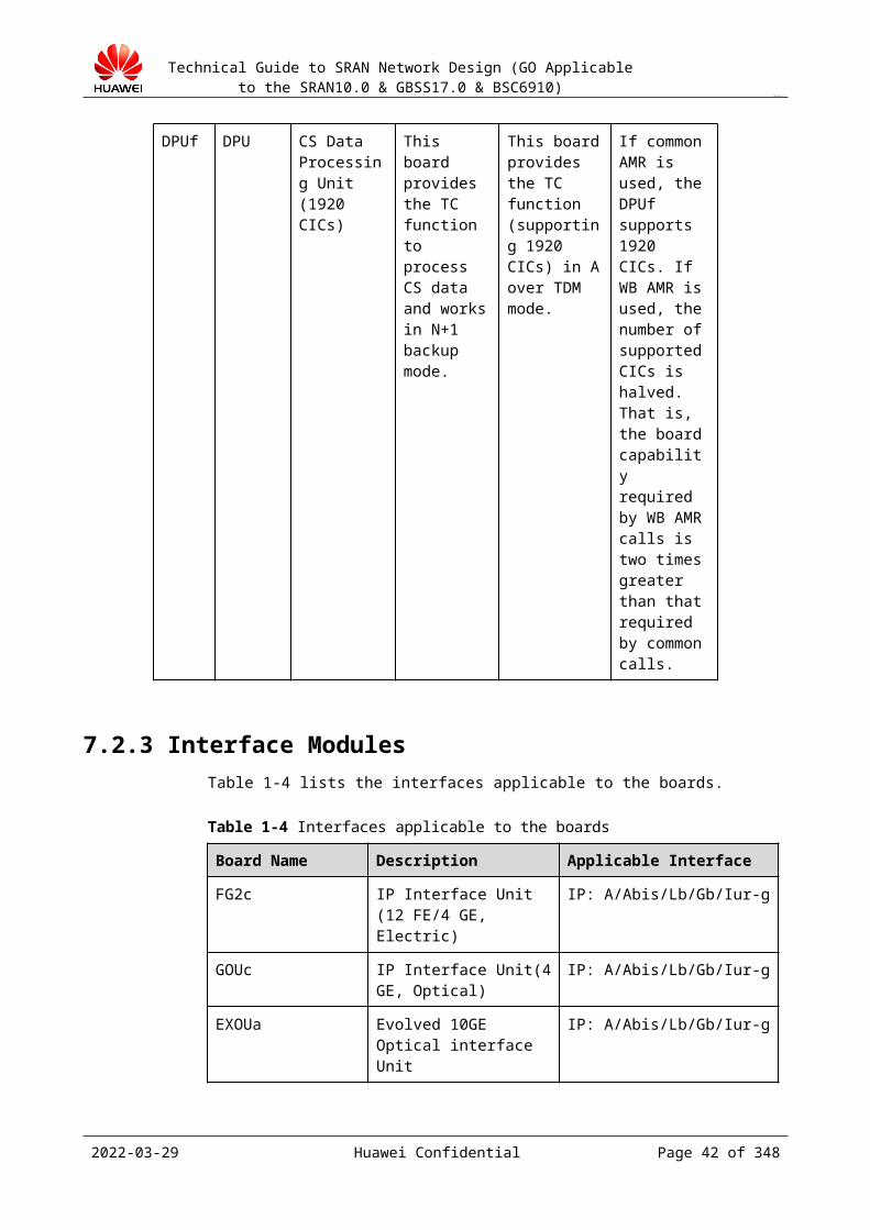
Technical Guide to SRAN Network Design (GO Applicable to the SRAN10.0 & GBSS17.0 & BSC6910)
CONFIDENTIAL
9 Parameters for Capacity Calculation
Please refer to the latest BSC6900 Capacity Calculation Manual which you can download from http://3ms.huawei.com.
http://3ms.huawei.com/mm/docMaintain/mmMaintain.do?method=showMMDetail&f_id=GSM14040308540024
10 Capacity Calculation
Please refer to the latest BSC6900 Capacity Calculation Manual which you can download from http://3ms.huawei.com.
http://3ms.huawei.com/mm/docMaintain/mmMaintain.do?method=showMMDetail&f_id=GSM14040308540024
Reference: Impact on Interface Transmission Bandwidth After VLAN Is Deployed
VLAN is a data exchange technology derived from traditional LAN.
VLAN allows LAN devices to be logically grouped into multiple network segments (that is, smaller LANs) to implement virtual workgroups. The hosts in the same VLAN communicate
2023-04-22 Huawei Confidential Page 42 of 258
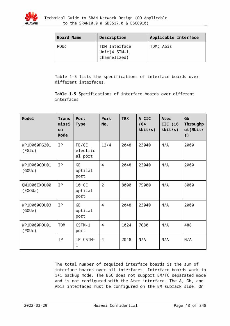
Technical Guide to SRAN Network Design (GO Applicable to the SRAN10.0 & GBSS17.0 & BSC6910)
CONFIDENTIAL
with each other through VLAN switches. The hosts in different VLANs are separated from each other and they only communicate with each other through routers. A VLAN is a broadcast domain, that is, a host in a VLAN can receive broadcast packets from the other hosts in the same VLAN but cannot receive any broadcast packets from other VLANs.
The advantages of VLAN are as follows:
Suppresses broadcast storm Improves transmission security Provides differentiated services
VLAN Frame Format
The VLAN frame format is defined in IEEE 802.1Q. Compared with a standard Ethernet frame, the VLAN frame is added with a four-byte VLAN tag in its header, as shown below.
The fields of the VLAN tag are described as follows:
TPID: specifies the VLAN tag protocol identifier defined by IEEE. If a VLAN frame complies with IEEE 802.1Q, TPID is permanently set to 0x8100.
VLAN priority: specifies the priority of a VLAN frame. The priority ranges from 0 to 7. Ethernet provides differentiated services based on the VLAN priority.
Canonical Format Indicator (CFI): specifies the format of a frame that is exchanged between the bus Ethernet and a Fiber Distributed Data Interface (FDDI) or between the bus Ethernet and the token ring network.
VLAN ID: specifies the VLAN to which a frame is to be sent. Each VLAN is identified by a VLAN ID.
Application scenario: Only Ethernet IP networks.
The related BSC6910 parameters are as follows:
VLANID: This parameter specifies the identifier of a VLAN. The VLAN ID mapping should be preconfigured in the BSC6910. According to the VLAN ID mapping, the BSC6910 determines the VLAN ID to send a VLAN frame. The BSC6910 supports two VLAN configuration modes:− Configuring VLAN by next hop:
The VLAN ID is determined according to the preconfigured mapping between the next-hop IP address and the VLAN ID.The related parameters are IPADDR and VLANID.
2023-04-22 Huawei Confidential Page 43 of 258
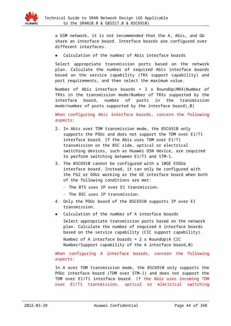
Technical Guide to SRAN Network Design (GO Applicable to the SRAN10.0 & GBSS17.0 & BSC6910)
CONFIDENTIAL
− Configuring VLAN by data flowThe VLAN ID is determined according to the preconfigured mapping between the SCTP link, IP path, and VLAN ID.The parameters related to SCTP link are SCTPLNKN, PATHID, and VLANID.
VLANPRI: This parameter specifies the priority of a VLAN frame.
VLAN configuration modes supported by different interfaces on the BSC6910 on the GSM networks are as follows:
The A and Abis interfaces support configuring VLAN by next hop or data flow. The Gb interface supports configuring VLAN by next hop. The Ater interface supports configuring VLAN by next hop or data flow when IP over
E1 is not in use.
Impact assessment: With the increasing deployment of IP networking, in particular, with the increasing deployment of VLAN networking on IP networks, VLAN tags have certain impact on IP transmission bandwidth over the Abis interface. The actual impact varies according to different compresses and transmission rate, and the average impact is about 3.5%.
Detailed calculation method:
If IP multiplexing (MUX) is not in use, a four-byte (32-bit) VLAN tag is added to a 20-ms voice (data) frame.
If MUX is in use, a four-byte (32-bit) VLAN tag is added to voice (data) frames that are transmitted at an interval of 20 ms. Therefore, VLAN tag resources are saved if MUX is in use.
2023-04-22 Huawei Confidential Page 44 of 258
Technical Guide to SRAN Network Design (GO Applicable to the SRAN10.0 & GBSS17.0 & BSC6910)
CONFIDENTIAL
11 Design of Resource Allocation
11.1 Design Overview11.1.1 Purpose of the Design
Review the traffic and BHCA load of each device based on accurate network planning information. If a load risk exists or the traffic exceeds the specifications, adjust the BTS homing. If the BTS homing cannot be adjusted, negotiate with the customer and marketing personnel to purchase more devices (under the guidance of marketing personnel).
Configure BSC boards in proper slots based on the BSC traffic and BHCA to balance the BSC load, improve the device resource usage, and improve the anti-attack capability.
Review the specifications information about the MSC, MGW, and SGSN to check whether the capacities are enough and assess the risk.
11.1.2 Input of the Design Device BOQ Network planning information (Obtain the information, including the BSC coverage,
traffic, LAC partitioning, and BTS homing from the on-site network planning department.)
Information about the equipment room, power supply, or transmission of the customer, and special requirements of the customer
11.2 BSC Load AllocationThis section assesses the BSC load risks, including the current traffic model and target traffic model based on the current device processing capability, and lists the percentages of the BHCA and traffic load of each BSC in the design specifications.
11.2.1.1 Design Principles The predicted BSC traffic load does not exceed 70% of the design specifications. The predicted BHCA load does not exceed 70% of the design specifications. TRXs are allocated to subracks evenly to balance the load and reduce signaling transfer
between subracks. The number of TRXs configured in each subrack
needs to be less than 70% (it is for flexible follow-up adjustment and expansion but is
2023-04-22 Huawei Confidential Page 45 of 258
Technical Guide to SRAN Network Design (GO Applicable to the SRAN10.0 & GBSS17.0 & BSC6910)
CONFIDENTIAL
not mandatory) of the specifications to facilitate follow-up site adjustment and expansion.
If the preceding principles conflict with the marketing BOQ, follow the marketing BOQ, and improve the overall system capacity by optimizing capacity resource allocation. If the traffic load or BHCA load exceeds 60%, experts in the Huawei headquarters assess the risk.
Confirm the BSC traffic capacity and BHCA specifications in the current configuration based on the configuration in the marketing BOQ.
Assess whether the BSC resource load meets the requirements based on the traffic model, traffic capacity, and BTS homing.
The BSC traffic calculated by the GSM NEP is the traffic capacity of the BSC. It is obtained based on the number of TRXs, number of BTSs, congestion rate, and erlang_B table. The actual traffic can be obtained from the customer or network planner. The calculation formula is as follows:
Actual BSC traffic = Predicted number of subscribers x Busy-hour traffic per subscriber Actual BSC BHCA = Predicted number of subscribers x Busy-hour BHCA per
subscriber Actual BSC traffic load = Actual BSC traffic/BSC traffic specifications Actual BSC BHCA load = Actual BSC BHCA/BSC BHCA specifications
Huawei's recommended expansion standards are as follows:
The number of TRXs configured for the BSC reaches 70% of the capacity specifications. The busy-hour traffic exceeds 70% of the specifications. The busy-hour BHCA exceeds 70% of the specifications. The busy-hour central processing unit (CPU) usage exceeds 70%. The SS7 link load exceeds 40%. The CIC traffic per line exceeds 0.7 ERL.
Output of the design
Table 11-1 BSC capacity planning table
BSCName
BTS Number
TrafficForecast
BHCAForecast
TRX Number
TRXCapacity
TRXPercent
TrafficPercent
BHCAPercent
For BHCA calculation note, see section Error: Reference source not found.
9.1.1 Signaling Storm
11.2.1.2 Concept of Signaling StormSignaling storms first rose on the 3G network. Under the impact of a large number of signaling messages, major signaling processing channels become the bottleneck of the
2023-04-22 Huawei Confidential Page 46 of 258

Technical Guide to SRAN Network Design (GO Applicable to the SRAN10.0 & GBSS17.0 & BSC6910)
CONFIDENTIAL
network, and CPU usage on the control plane of both the radio network controller (RNC) and NodeB increases sharply. Moreover, a smart terminal attempts to access the network at an increasingly short interval, once some signaling messages are discarded. Consequently, the already heavy signaling traffic becomes even heavier, which causes a signaling storm. The signaling storm threatens equipment security of both the RNC and NodeB, and seriously decreases the processing capacity of the system. A typical phenomenon is that the serving capacity of the system decreases. That is, high RRC and radio access bearer (RAB) rejection rates occur when the data traffic is low.
11.2.1.3 Current State of Signaling StormAs the penetration rate of smart terminals increases, the feature of high signaling traffic on smart terminals stands out. Statistics shows that smart terminals have seen an increase in signaling traffic, which is 15 times that in traditional terminals. Part of the UMTS network has been affected by signaling storms. For example, some subscribers of China Unicom in Beijing failed to access the network after the congestion rate increases in the core network (CN) of the X office in Beijing in 2010. Some subscribers of StarHub in Singapore had the same problem in 2011. Moreover, some subscribers of TELUS in Canada failed to access the network after many signaling messages were discarded by the CN of the X office. Some subscriber of NTT DoCoMo in Japan failed to access the network, and performance and reliability of the network were affected for the same reason.
11.2.1.4 Causes of Signaling StormA signaling storm rises from too many signaling messages, which are caused by the following factors:
Smart phone penetration rate increases year on year. After smart phones were introduced, services, including low-traffic services, have been diversified. Smart terminals and mobile network services are increasingly popular. To provide better user experience, smart terminals periodically send heartbeat packages to the network server to synchronize the information at the request of such applications as QQ and MSN Messenger. Heartbeat packages are small data packages of hundreds or thousands of bytes sent every dozen seconds or tens of seconds. The heartbeats of different applications and the system result in frequent PS calling.
According to the 3rd Generation Partnership Program (3GPP), a terminal in the connected state can send a signaling connection release indication (SCRI) to the RNC in some scenarios. An SCRI carries different cause values in different scenarios. For example, a smart terminal sends an SCRI with the cause value being "UE Requested PS Data session end." to indicate the end of a PS data session.
The greatest bottleneck of an MS lies in the battery. To save power, a smart terminal automatically sends an SCRI to the RNC at the end of a data session to release the RRC signaling connection and returns to the idle state. However, some applications on the terminal need to periodically send heartbeat packages to the application server. As a result, a connection to the RRC is re-established, and the UE returns to the connected state. After a small-size heartbeat package is sent, the RRC connection is released again, and the cycle goes on and on. As many as 30 pieces of signaling over the Uu interface and Iub interface are required in every PS data transmission, which makes the traffic model change significantly and the packet calling attempts exceed the voice calling attempts.
11.2.1.5 Impact of Smart Phones on the 2G NetworksSignaling storms in the UMTS network rise from too many signaling messages caused by a large number of smart phones and low-traffic services. Whether signaling storms are likely to
2023-04-22 Huawei Confidential Page 47 of 258

Technical Guide to SRAN Network Design (GO Applicable to the SRAN10.0 & GBSS17.0 & BSC6910)
CONFIDENTIAL
raise in the 2G networks as the penetration rate of smart phones rapidly increases? An analysis is made in multiple dimensions.
Impact of the heartbeat service model of smart phones over the average service model in the GSMUse the live network in Hangzhou city of China Mobile Group Zhejiang Company Ltd as an example. As shown in Figure 11-1, the heartbeat service model of smart phones is the same as the average service model in the GSM.
Figure 11-1 Average service duration
Impact of access to the GSM over the core network− When uplink data exists on the MS, the MS is switched to the Ready state and
directly sends the data. No authorization or encryption is required.− The state changes from Ready to Standby, if the time when no signaling message
exists over the Gb interface exceeds a time prescribed by a timer on the SGSN side.− When downlink data exists on the network side, the Gb interface sends a paging
message. In response, the MS returns a correct logical link control (LLC) frame.− Frequent service triggering does not increase signaling messages other than paging
messages over the Gb interface.
To sum up, signaling interworking does not exist between the GSM service access and the core network.
2023-04-22 Huawei Confidential Page 48 of 258
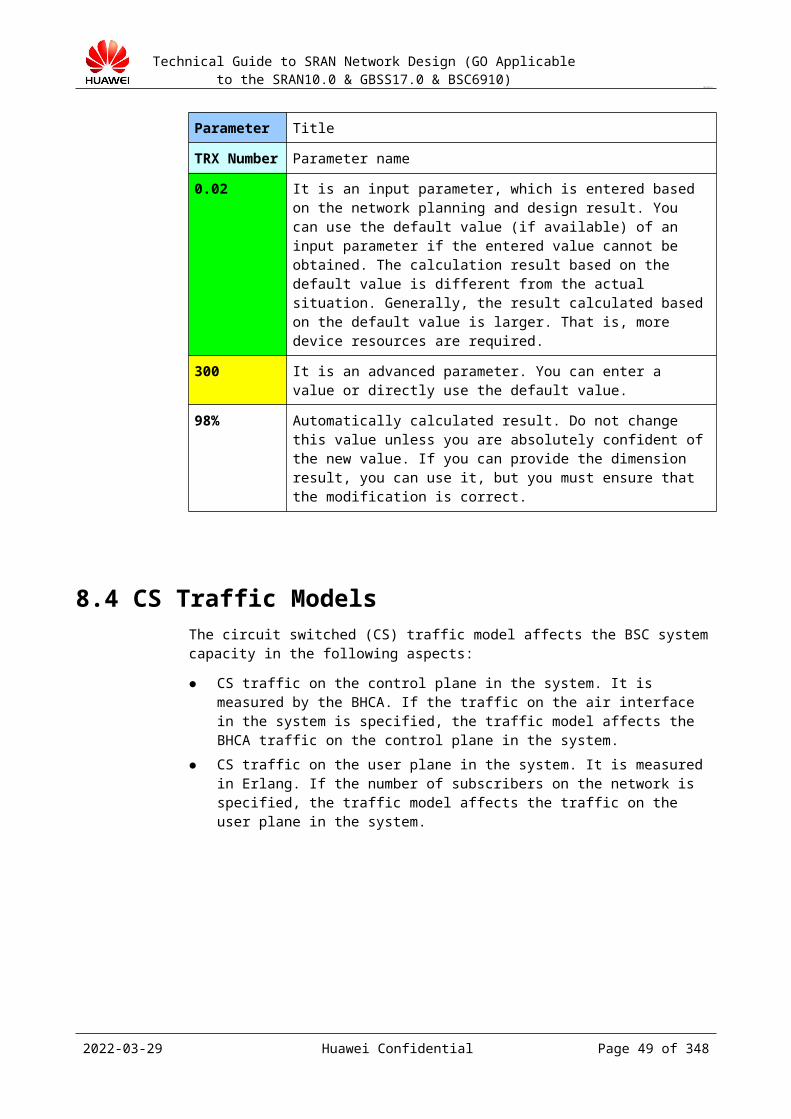
Technical Guide to SRAN Network Design (GO Applicable to the SRAN10.0 & GBSS17.0 & BSC6910)
CONFIDENTIAL
Signaling in each access to the GSMWhen the GSM network is accessed, the number of signaling messages is less than three on the wireless network side, much less than the 25 signaling messages in the UMTS network (not considering interworking with the core network).
Signaling load on the common control channel (CCCH)− Based on the loading capacity of the base station subsystem (BSS), the loading
efficiency of the packet data channel (PDCH) is 9 kbit/s when a cell uses a maximum of 64 PDCHs. Two CCCHs can meet the requirements of the PS signaling load when the cell enables the multi-CCCH function.
− The CCCH resource usage efficiency can be further improved by multi-layered paging.
− Channel management by layer improves signaling resource usage efficiency, gives priority to access of voice services, and prevents the heavy PS load from affecting the CS services.
− The CCCH resources can bear the signaling load and do not form a bottleneck.
2023-04-22 Huawei Confidential Page 49 of 258

Technical Guide to SRAN Network Design (GO Applicable to the SRAN10.0 & GBSS17.0 & BSC6910)
CONFIDENTIAL
Signaling load on the LAPD resourcesThe load on the LAPD link mainly comes from the load on the B RSL link, which affects the CS paging messages, CS immediate assignment messages, PS paging messages, and PS immediate assignment messages. The LAPD resources can bear the signaling load and do not form a bottleneck.
− The number of LAPD links required by the PS service is calculated according to the following specifications: On a 16 kbit/s timeslot, the maximum signaling load has 2000 Bytes/s.
− Number of bytes in paging messages: 21 Bytes− Number of bytes in PS immediate assignment messages: 27 Bytes
The eXtensible processing unit (XPU) resourcesThe following figure describes the subsequent networking planning requirements of China Mobile Group. Huawei's XPU design specifications can meet the BHCA requirements and do not form a bottleneck. In all-IP mode, the latest product BSC6910 has a BHCA specification of 52,000 K, which is much higher than the specification of the BSC6900.
2023-04-22 Huawei Confidential Page 50 of 258

Technical Guide to SRAN Network Design (GO Applicable to the SRAN10.0 & GBSS17.0 & BSC6910)
CONFIDENTIAL
− Flow control on the XPU of the BSC ensures that the PS paging times in a period and the channel requests by the PS services in a period are controllable.
− The increase in signaling services caused by the increase in the traffic of the current data services does not have an impact over the XPU of the BSC. In event of sudden increase in signaling messages, the flow control on the XPU guarantees the loading security on the XPU and deals with the impact of the PS services over the CS services.
− The BSC BHCA specification of the BSC6910 is 52000 K (all-IP networking mode). The data processing unit (DPU) resources
As the version is updated, the DPU supports an increasing large number of PDCHs. The DPU resources can bear the signaling load and do not form a bottleneck.
The BSC6910 does not use the XPU and DPU boards separately. Functions of both XPU and DPU boards are integrated in EGPUa boards. An EGPUa (GCUP) board supports 1000 TRXs and 3000 PDCHs, almost twice the number of TRXs (512) and PDCHs (1024) supported by the original XPU and DPU boards. Based on the above analysis, the BSC6910 does not have a bottleneck in processing capability of the XPU and DPU boards.
Impact of smart phones over the 2G network (based on the data of China Mobile Group Zhejiang Company Ltd)− The 2G network subscriber base remains unchanged. However, traffic of smart phone
users is 2.9 times that of non-smart phone users.− Market penetration rate of small phones reached 19% in 2011. The total traffic
increases to 2.35 times that of the current traffic, if non-smart phones are substituted by smart phones.
− The average loading efficiency of the PDCH is 4 kbit/s on the live network. When the loading efficiency of the PDCH increases to 9 kbit/s and the specification of equipment is improved to support more channels, the traffic in the 2G network can increase to 2.35 times the current traffic.
2023-04-22 Huawei Confidential Page 51 of 258
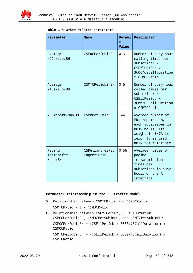
Technical Guide to SRAN Network Design (GO Applicable to the SRAN10.0 & GBSS17.0 & BSC6910)
CONFIDENTIAL
Heartbeat duration of application services is adjusted to reduce the impact over the network− Tencent increases the heartbeat duration of its program QQ (30 to 180s) to reduce the
impact over the network.− Apple launched APNS, a server to send notification messages to such terminals as
iPhone in a secure and timely manner, to manage heartbeats and increase heartbeat duration.
Development trendView of the operator (VF):The GSM network will evolve to be a low-cost and low-traffic network for the following reasons:− The spectrum resources of the GSM will decrease because part of the resources is
given to the UMTS and LTE in spectrum refarming. As a result, configuration for the BTS degrades in the GSM.
− The legacy UE evolves towards smart phones and the traffic becomes increasingly low.
11.2.1.6 Conclusion of Impact of Smart Phones over the 2G Network
Based on the analysis above, signaling storms do not occur on the 2G network. The conclusion may be updated depending on the future development.
11.3 BSC Board Layout Design11.3.1 Design Guide
Design board layout between subracks for the BSC based on the BOQ for load balancing and work out the board configuration figure.
Purpose of board layout design:
Decrease the number of messages forwarded between subracks to improve the BSC performance.
Balance the load between subracks to improve the anti-attack capability.
2023-04-22 Huawei Confidential Page 52 of 258
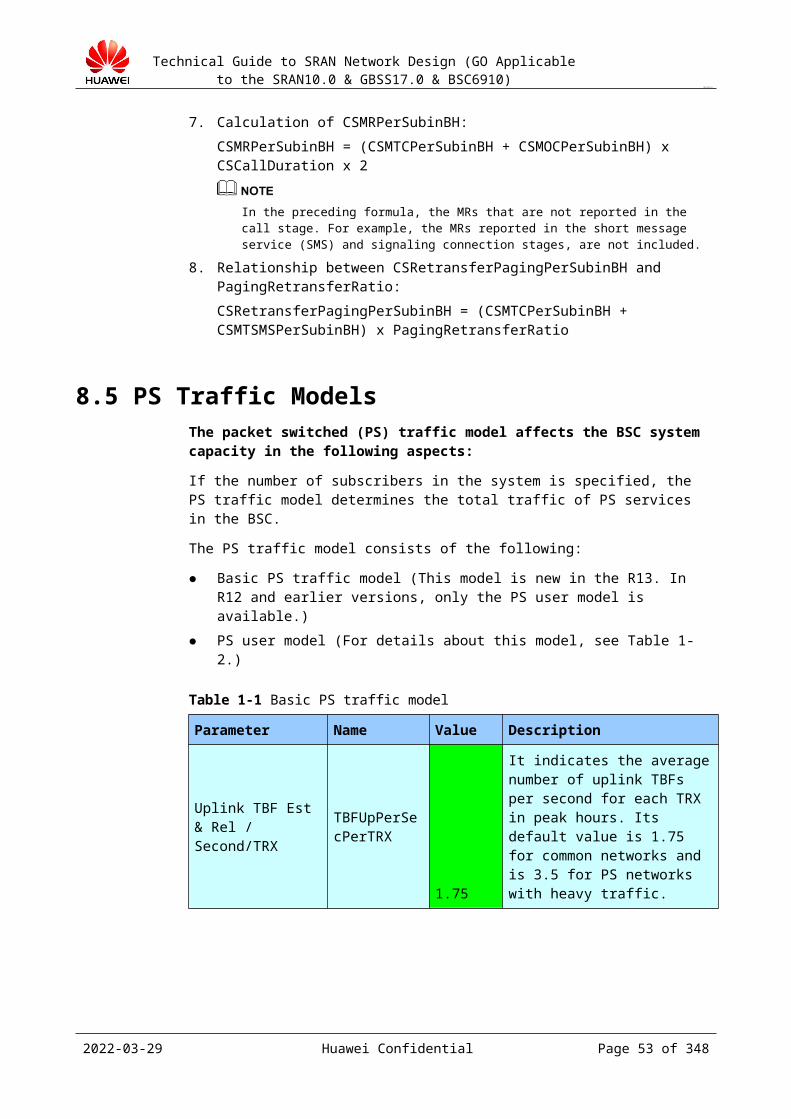
Technical Guide to SRAN Network Design (GO Applicable to the SRAN10.0 & GBSS17.0 & BSC6910)
CONFIDENTIAL
Reserve certain port redundancy to facilitate site adjustment and expansion. Deploy logical boards of the same type in a centralized manner to reduce interleaving
with boards of different types. Deploy electrical interface boards on one side and optical interface boards on the other
side to facilitate cable connection. Use different boards to provide 2G and 3G services to reduce the impact of software
upgrade and board adjustment on services. Allocate slots properly to maximize the board processing capability (the switching
capability of the slots on the backplane differs).
In an office where traffic is heavy, board layout is important. Proper board resource allocation can maximize the processing capability of the device, balance the load, and improve the anti-attack capability of the device.
11.3.1.1 BSC6910 Design PrinciplesDesign Principles (Use the NEP Tool to automatically generate the board layout figure, and the following principles are only for your reference)
Reduce inter-subrack signaling transfer. Ensure that the processing capabilities of the Abis interface board, A interface board, and embedded packet control unit (PCU) in the same subrack match each other.
Balance the load between the subracks of the BSC. The GMPS needs to process data, such as operation and maintenance (O&M), traffic measurement, and alarms. The XPU load is relatively high. The number of TRXs configured in the GMPS subrack is relatively small. Therefore, in the case of Abis interface board imbalance between BM subracks, the number of Abis interface boards configured for the GMPS is small.
Install interface boards in rear slots and service processing boards in non-fixed slots. Therefore, preferentially install service processing boards in front slots. Deploy the A interface board, Abis interface board, and Gb interface board separately, and deploy logical interface boards of the same type (A interface board, Abis interface board, and Gb interface board) together.
Deploy boards of the same type (physical boards or logical boards) from the middle to sides in the subrack to facilitate follow-up board expansion.
Deploy optical interface boards and electrical interface boards on different sides in the subrack. Do not deploy them on the same side.
The ENIU board (data service identification board with a specification of 1000 Mbit/s over the Gb interface) can be inserted in slots that do not hold the OMU and GGCU of the BM subrack. The recommended slots are slots 2 and 3, and the priorities of slots are 2 to 7. ENIU boards are preferably configured with the same subracks of the Gb interface board (to reduce traffic between subracks). The system can be configured with a maximum of 15 ENIUa boards. The ENIUa board can only be configured in 10 G slot.
When a customer purchases and uses Huawei's Nastar, the ESAUa boards need to be inserted in the BSC6910. The ESAUa board may be inserted in other idle slots other than the fixed slots. An ESAUa board occupies two slots. Configure the ESAUa board in the active subrack.
Deployment of 10G Slots in the BSC6910
2023-04-22 Huawei Confidential Page 53 of 258

Technical Guide to SRAN Network Design (GO Applicable to the SRAN10.0 & GBSS17.0 & BSC6910)
CONFIDENTIAL
The following describes a method for configuring a main subrack:
Every BSC6910 must be configured with only one PCS main subrack.
Assign EOMUa switch boards to slot 10 to 13. SCUb boards are assigned to slot 20 and 21, and EGPUa boards for resource management are assigned to slot 8 and 9.
Configure the BSC6910 with two PCS GCUa boards, when a GPS clock is required. Configure the BSC6910 with two PCS GCGa boards, when a GPS clock is not required. Assign GCUa/GCGa boards to slot 14 and 15.
When a customer purchases Huawei's Nastar, ESAUa boards are required in the BSC6910.
EGPUa/ESAUa boards can be inserted in other idle slots other than the fixed slots. The following assignment is recommended:− Assign ESAUa boards to slot 0 and 1.− Preferred slots for EGPUa boards are slot 2 to 7.
The following assignment is recommended for GOUc/FG2c/EXOUa/POUc boards:− EXOUa boards can only be assigned to slot 16 to 19 and slot 22 to 25.− Preferred slots for GOUc/FG2c/POUc boards are slot 16 to 19 and slot 22 to 25.
When these slots are inadequate, they are assigned to slot 26 to 27.
2023-04-22 Huawei Confidential Page 54 of 258

Technical Guide to SRAN Network Design (GO Applicable to the SRAN10.0 & GBSS17.0 & BSC6910)
CONFIDENTIAL
The following describes a method for configuring an extended processing sub rack:
SCUb switch boards are assigned to slot 20 and 21. If a customer purchases Huawei's Nastar, ESAUa boards are required. Configure ESAUa
boards in the main subrack. EGPUa boards can be assigned to other idle slots other than slot 20 and 21. The
recommended slots are slot 0 to 13. GOUc/FG2c/EXOUa/POUc boards are interface boards. EXOUa/POUc boards can only be assigned to slot 16 to 19 and slot 22 to 25. Preferred slots for GOUc/FG2c boards are slot 16 to 19 and slot 22 to 25. When these
slots are inadequate, assign GOUc/FG2c boards to slot 26 and 27.
Principles of EGPUa/EXPUa configuration
2023-04-22 Huawei Confidential Page 55 of 258

Technical Guide to SRAN Network Design (GO Applicable to the SRAN10.0 & GBSS17.0 & BSC6910)
CONFIDENTIAL
Service processing boards used by the BSC6910 include EGPUa and EXPUa boards. EXPUa boards are used in the GSM other than the Universal Mobile Telecommunications System (UMTS). Logical types of service processing boards are RMP, GCUP, GMCP, or NASP.
EXPUa and EGPUa boards can be configured in both GO and GU mode. By default, EXPUa boards are configured in GO mode and EXPUa in GU mode.
In the UO mode, only EGPUa boards can be configured, instead of EXPUa boards. Principles of EGPUa/EXPUa configuration for the RMP: In the GO mode, the RMP can
use EXPUa or EGPUa boards. By default, the RMP uses the same board as the GCUP. In the GU/UO mode, the RMP can only use EGPUa boards.
Principles of EGPUa/EXPUa configuration for GMCP: In the GO/GU mode, the GMCP can use XPUa or EGPUa boards. By default, the GMCP uses the same board as the GCUP.
Principles of EGPUa/EXPUa configuration for the NASP: The NASP can only use EGPUa boards, instead of EXPUa boars.
Principles of RMP configuration
The system is configured with only one RMP pair in the MSP subrack, one active and one standby board.
Principles of GCUP configuration
Service processing boards are configured according to the BSC capacity planning. Different calculation methods are applied for the BSC6910 and BSC6900.
In the BSC6900, numbers of XPUa/XPUb boards on the control plane, DPUd/DPUg boards on the PS user plane, and DPUc/DPUf boards on the CS user plane are calculated differently. For boards on the control plane, the number is the larger value calculated based on the planned TRX number and the comprehensive BHCA. For boards on the PS user plane, the number is calculated based on the number of PDCHs. For boards on the CS user plane, the number is calculated based on the predicated traffic volume.
In the BSC6910, the EGPUa boards are used. Each GCUP board has the following specifications: BTS number, cell number, TRX number, comprehensive BHCA, number of PDCHs, and traffic volume. Divide the site-planned overall specification by the basic specifications above respectively, to obtain several board numbers. The greatest of these numbers is the number of boards to be configured.
Table 11-1 describes the specifications of the EGPUa boards.
2023-04-22 Huawei Confidential Page 56 of 258
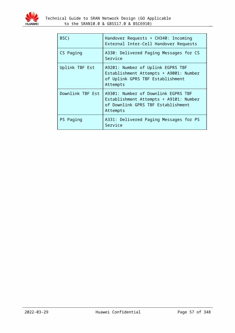
Technical Guide to SRAN Network Design (GO Applicable to the SRAN10.0 & GBSS17.0 & BSC6910)
CONFIDENTIAL
Table 11-1 Specifications of the EGPUa board
TRX 1000
Cell 600
BTS 600
Traffic volume 6250 6.25 Erlang per TRX on average
PDCH 3000 3 PDCHs per TRX on average
PS throughput
300 Mbit/s 3000 × 100 kbit/s, EGRPS2A
Comprehensive BHCA
2200 K
The value is based on the actual benchmark weights and considers the PS BHCA. The PS BHCA is based on the comprehensive BHCA of Huawei's default traffic model.
GCUP boards do not support the active/standby mode. The number of redundant boards can be manually specified in the redundancy configuration. By default, if the number of GCUP boards required is X in capacity calculation, another GCUP board is configured. Each BSC is configured with at least two redundant boards.
Principles of GMCP configuration
GMCP boards are configured according to the IBCA deployment requirements. If the IBCA function is enabled, one GMCP board supports 2048 TRXs. GMCP boards do not support the active/standby mode.
Principles of NASP configuration
NASP boards are configured according to the deployment requirement of network assisted WLAN identification. If this feature is enabled, a BSC is configured with only once NASP board.
Principles of ENIUa configuration
If the feature of intelligent service identification is enabled, ENIUa boards are required. A BSC is configured with only one ENIUa board.
Principles of ESAUa configuration
If a customer purchases the Nastar, the ESAUa board needs to be configured in the BSC. A BSC is configured with only one ESAUa board.
2023-04-22 Huawei Confidential Page 57 of 258
Technical Guide to SRAN Network Design (GO Applicable to the SRAN10.0 & GBSS17.0 & BSC6910)
CONFIDENTIAL
12 Naming Rules Design
12.1 Design Overview12.1.1 Purpose of the Design
This section designs the numbering and naming rules for all the NEs on the network to make network topology clear and facilitate network management.
Standard numbering and naming facilitate maintenance. Directly locate faults by using alarm information to improve maintenance efficiency.
12.1.2 Input of the Design Information, such as geographical distribution and the number of NEs, area names,
office names, and NE types NE naming specifications and requirements of the customer. In the high-level design
(HLD), naming rules of NEs are determined based on naming conventions and planning requirements of the customer, and Huawei's naming rules.
This document describes the naming and numbering rules recommended by Huawei. However, most customers use their own NE naming rules. In actual applications, communicate with the customer and then determine the naming and numbering rules based on the customer requirements and the rules recommended in this document.
12.2 NE Naming Rules12.2.1 Naming Rules of Areas
Network design is performed based on areas. Therefore, it is necessary to name the areas.
Use the short name of the geographical name of an area to name the area. For a geographical name in China, use the capital letters in the full pinyin name.
For example, the publicly known short name of Lagos, Nigeria is LOS. Use LOS as the name of Lagos.
2023-04-22 Huawei Confidential Page 58 of 258
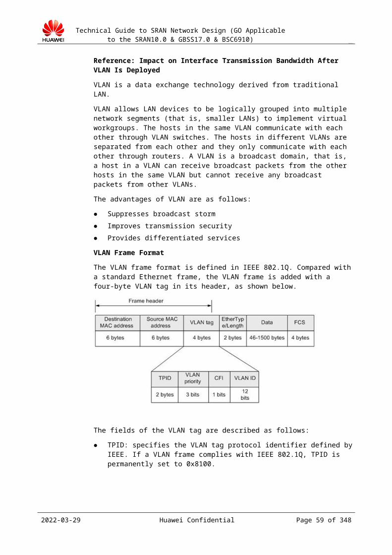
Technical Guide to SRAN Network Design (GO Applicable to the SRAN10.0 & GBSS17.0 & BSC6910)
CONFIDENTIAL
For example, the capital letters of the full pinyin name of Guangzhou is GZ. Use GZ as the name of Guangzhou.
12.2.2 Naming Rules of OfficesDevices are installed in offices. Therefore, office naming is part of NE naming, and it is important for locating NEs quickly.
Use the first three letters in the full English geographical name of an office. For a geographical name in China, use the capital letters in the full pinyin name.
For example, a BSC office is located in Adekula in Nigeria. Use ADE as the name of the Adekula office.
For example, a BSC office is located in Dian Xin Guang Chang in Xi'an. Use DXGC as the name of the Dian Xin Guang Chang office.
If the short names of two are the same, lengthen the short name of one office to distinguish them.
For example, two BSC offices are located in Okuno and Okuani in Nigeria. Use OKUN and OKUA as the names of the offices in Okuno and Okuani respectively.
12.2.3 Naming Rules of ManufacturersThe network of an operator may use the devices of multiple manufacturers. Naming the manufacturers and using the manufacturer names in NE naming can help quickly distinguish the manufacturer of an NE.
Use the commonly used manufacturer short names in the telecom field.
Table 12-1 Manufacturer short names
Manufacturer Short Name
Huawei HW
Ericsson ERI
ZTE ZTE
Nortel NOR
Motorola MOT
Samsung SAM
Alcatel-Lucent AL
UTSTARCOMM UT UT
Nokia-Siemens NSN
Cisco CIS
There are numerous manufacturers, and this document lists only the commonly known ones.
2023-04-22 Huawei Confidential Page 59 of 258

Technical Guide to SRAN Network Design (GO Applicable to the SRAN10.0 & GBSS17.0 & BSC6910)
CONFIDENTIAL
12.2.4 Naming Rules of NEsThis document describes the naming rules only of the NEs on the radio side and the NEs closely related to the radio side. The short names of the NEs are as follows:
Table 12-1 NE short names
Network Element Type Description
BTS Base transceiver station
eGBTS Evolved GSM Base Transceiver Station
BSC Base station BSC
AN Access network
OMU Operation and maintenance unit
MSC Mobile switching center
MSCe Mobile switching center emulation
MGW Media gateway
HLR Home location register
STP Signaling transfer point
SGSN Serving GPRS support node
GGSN Gateway GPRS support node
DNS Domain name server
BG Border gateway NE08, NE40
RT Router
LSW LAN switch
FW Firewall
M2K M2000 server
Huawei recommends the following naming rules for NEs other than the BTS:
<A>_<B>_<C><D><E>
A stands for the short name of the area where the NE is located.
B stands for the short name of the office where the NE is located.
C stands for the short name of the manufacturer of the NE.
D stands for the short name of the NE.
E stands for the sequence number in the area where the NE is located.
For example, the second BSC (manufactured by Huawei) in Xi'an is located in Dian Xin Guang Chang, and the BSC is named as follows:
2023-04-22 Huawei Confidential Page 60 of 258

Technical Guide to SRAN Network Design (GO Applicable to the SRAN10.0 & GBSS17.0 & BSC6910)
CONFIDENTIAL
XA_DXGC_HWBSC2
For example, the first PDSN (manufactured by ZTE) in Lagos in Nigeria is located in Adekula, and the PDSN is named as follows:
LOS_ADE_ZTEPDSN1
This document recommends this naming rule. Engineers can determine the specific naming rule based on actual conditions. For example, if the devices on the operator's network are all provided by Huawei, omit the manufacturer name to simplify the NE names.The OMU and PCU are embedded in the BSC. However, they are independent NEs in terms of GSM network structure. Therefore, name them independently. The OMU and the PCU are named based on the BSC.
Generally, the number of BTSs is large. Therefore, simplify the BTS names. Name BTSs as follows:
<A><B>
A stands for the name of area where the BTS is located, or the name of the property company that manages the area where the BTS is located.
B stands for the BTS ID. For details about BTS IDs, see 12.3.2 "Numbering Rules of BTS IDs."
For example, BTS2 in Parkview in Nigeria is named Parkview2.
12.2.5 Naming Rules of Signaling PointsA signaling point refers to the originating signaling point code (OPC) or destination signaling point code (DPC) of the BSC. The DPC naming rule is as follows:
The DPC naming rule is as follows:
<A>_OPC<B>
The DPC naming rule is as follows:
<A>_DPC<B>
A stands for the name of the BSC to which the DPC belongs. For details about BSC names, see 12.2.4 "Naming Rules of NEs."
B stands for the sequence number of the DPC in the BSC to which the DPC belongs.
For example, the second DPC of XA_DXGC_HWBSC2 is named as follows:
XA_DXGC_HWBSC2_DPC2
An OPC or DPC consists of 1 to 49 characters.
12.3 NE Numbering Rules12.3.1 Numbering Rules of Entity IDs
An entity ID is a BSC ID. It is used to identify BSCs. The combination of MSC ID+BSC ID can uniquely identify a BSC in the system. The value range is 0 to 65535. Each BSC ID in the same MSC must be unique.
2023-04-22 Huawei Confidential Page 61 of 258
Technical Guide to SRAN Network Design (GO Applicable to the SRAN10.0 & GBSS17.0 & BSC6910)
CONFIDENTIAL
Number the BSCs with the entity IDs starting from 1 based on the order in which the BSCs are launched in commercial use.
12.3.2 Numbering Rules of BTS IDsA BTS ID is used to uniquely number a BTS in the BSC. The value range is 0 to 7999. Each BTS ID in the BSC must be unique. Provide this numbering rule after you communicate with the RF network planner. Name BTSs based on geographical areas. That is, allocate a consecutive number range to a geographical area. Then, the maintenance personnel can learn the geographical area where the BTS is located from the BTS ID (BTS name).
12.3.3 Numbering Rules of Cell IDsA cell ID is used to uniquely number a cell in the BSC. The value range is 0 to 7999. Each cell ID in the BSC must be unique. Provide this numbering rule after you communicate with the RF network planner.
12.3.4 Numbering Rules of LACsIn actual applications, the RF network planner determines the LAC numbers.
12.3.5 Numbering Rules of MCCs and MNCsEach country has a mobile country code (MCC). The operator provides the MCC. Each country has multiple mobile network codes (MNCs). The operator provides the MNC.
MCC+MNC+LAC+CI comprise the cell global identifier (CGI) of a cell. A CGI can uniquely identify a cell.
12.3.6 Numbering Rules of SPXs and DPXsAn SPX uniquely identifies an originating signaling point. The value range is 0 to 4. Configure up to five originating signaling points. Use four originating signaling points for GSM and reserve one for universal mobile telecommunications system (UMTS) for follow-up GU convergence expansion.
A DPX uniquely identifies a destination signaling point. The BSC allocates indexes to all destination signaling points. The indexes range from 0 to 427, that is, there can be up to 428 destination signaling points.
2023-04-22 Huawei Confidential Page 62 of 258

Technical Guide to SRAN Network Design (GO Applicable to the SRAN10.0 & GBSS17.0 & BSC6910)
CONFIDENTIAL
13 BSC6910 Networking Principles
This chapter describes the principles, advantages, and disadvantages of the mainstream networking of the IP interface of the BSC6900.
13.1 Technical Principles13.1.1 Overview
Table 13-1 lists the advantages and disadvantages when the GBSS15.0 BSC6910 adopts the typical networking mode of IP transmission resource pool.
Table 13-1 Advantages and disadvantages when the GBSS15.0 BSC6910 adopts the typical networking mode of IP transmission resource pool
Networking Scheme Description Advantages Disadvantages
Promoted scheme: Pool of independent interface boards
Each port of the router works in load-sharing mode. The independent BSC interface boards form the resource pool.
Basic reliability: The BTS is homed to BSC's multiple interface boards that provide resource pool, thereby generating a 1:N protection.
Low hardware cost: Multiple interface boards work independently to dynamically balance the load, thereby providing the highest usage.
Low maintenance
The reliability is low. The SCTP is configured to multi-homing, resulting call drop for the ongoing calls instead of the newly connected subscribers.
2023-04-22 Huawei Confidential Page 63 of 258
Technical Guide to SRAN Network Design (GO Applicable to the SRAN10.0 & GBSS17.0 & BSC6910)
CONFIDENTIAL
cost: The maintenance is IP-path-free configuration. IP address can be added on the core network device without changing the configuration on the BSC. The configuration of the network device is simple and ports can be easily added to a board.
High adaptability: This scheme has no special requirements on network device configuration.
Optional scheme 1: Pool of active/standby interface boards+dual-active ports
Each port of the router works in load-sharing mode. The BSC interface boards form the resource pool, in which the interface boards with dual-active ports work in active/standby mode. The ports work independently. The gateways also work in active/standby mode.
High reliability: Fault of port or board does not affect services. In addition, the 1:N protection of resource pool is configured between multiple pairs of interface boards.
Low hardware cost: Multiple pairs of interface boards dynamically balance the load, thereby providing the highest usage.
Low maintenance cost: The maintenance is IP-path-free configuration. IP address can be added on the core network device without changing the configuration on the BSC.
After a switchover in case of a fault, one port takes over the services from another, affecting those excess services.
Compared with the solution with independent boards, the data processing and connection capabilities decreases by half.
There are special requirements on the configuration of network devices, for example, active/standby route policies are required.
Optional scheme 2: Pool of active/standby interface boards+manual
The ports of the router work in pairs using the Virtual Router
High reliability: Fault of port or board does not
High hardware cost: The number of port and interface boards doubles
2023-04-22 Huawei Confidential Page 64 of 258
Technical Guide to SRAN Network Design (GO Applicable to the SRAN10.0 & GBSS17.0 & BSC6910)
CONFIDENTIAL
active/standby link aggregation groups (LAGs)
Redundancy Protocol (VRRP). The BSC interface boards working in active/standby mode form the resource pool. The ports work in active/standby mode. The ports work independently.
affect services. In addition, the 1:N protection of resource pool is configured between multiple pairs of interface boards.
Compared with non-pool solutions, the hardware cost is lower. Multiple pairs of interface boards dynamically balance the load, thereby providing the highest usage.
Low maintenance cost: The maintenance is IP-path-free configuration. Transmission capacity expansion and adjustments do not require migration.
Reconstruction from the solution of active/standby interface boards with dual-active ports requires few changes. Only small changes are required on the BSC.
compared with other two resource pool solutions.
Complicated configuration: This scheme has special requirements on the configuration of network devices, for example, the router requires the configuration of VRRP, VLANIF, and layer-2 interface. The BSC requires the configuration of dual BFD+ARP detection.
The trunk connection between routers may not be reliable and affects the bandwidth. If the trunk is disconnected, services may be affected. If the bandwidth is insufficient, services are congested.
Table 13-2 lists the advantages and disadvantages when the BSC6910 does not adopt the typical networking mode of IP transmission resource pool.
Table 13-2 Advantages and disadvantages when the BSC6910 does not adopt the typical networking mode of IP transmission resource pool
Networking Scheme
Description Advantages DisadvantagesSelection Principle (Sub-Scenario)
Promoted scheme: Pool of active/standby
The ports of the router work in pairs using the VRRP. The BSC interface boards work in active/standby
The implementation is simple, and the application technology is proven.
Complicated configuration: The router requires the configuration of VRRP, VLANIF, and layer-2 interface. The
The promoted solution is the default solution. Try your best to recommend this
2023-04-22 Huawei Confidential Page 65 of 258

Technical Guide to SRAN Network Design (GO Applicable to the SRAN10.0 & GBSS17.0 & BSC6910)
CONFIDENTIAL
interface boards+manual active/standby LAGs (pool of independent IP addresses)
mode with manual active/standby LAG. Either the active or standby port bears the data streams.
BSC requires the configuration of dual BFD+ARP detection.
The trunk connection between routers may not be reliable and affects the bandwidth. If the trunk is disconnected, services may be affected. If the bandwidth is insufficient, services are congested.
solution to the customer.
Optional scheme 1: Pool of active/standby interface boards+dual-active ports (pool of independent IP addresses)
Ports of routers work in load-sharing mode. Each port provided by the active and standby boards of the BSC is dual-homed to one router.Divide the signaling and IP addresses of the local and peer ends into two groups, in which one group of IP is routed to the left path and another group of IP is routed to the right path through the high-priority route configuration, thereby achieving load sharing. Furthermore, the two routes work in backup mode, improving reliability.
Load sharing is implemented. The router and network path usage is increased.
Effective load sharing: The load both in the sending and receiving directions are shared. In addition, an end-to-end deployment can be implemented, that is, dual-path protection is configured for intermediate networks.
The data flow path is clear and consistent in sending and receiving, which provides good maintainability and helps fault location and QoS monitoring.
Complicated planning and configuration: IP addresses need to be divided to two groups. Different route priorities are configured for each group.
The customer requires load-sharing networking which satisfies the following requirements: Services address
in pairs must be configured for core network devices.
Active/standby route policies are required.
Not recommended: independent interface board
Ports of routers work in load-sharing mode. Two independent boards are connected to two routers, respectively. The ports are set to LAG mode. In addition, inter-board dual-homing
Basic reliability: The BTS is homed to BSC's multiple interface boards that provide resource pool, thereby generating a 1:N protection. The
The reliability is low. Services are affected if the board is faulty.
Not recommended
2023-04-22 Huawei Confidential Page 66 of 258
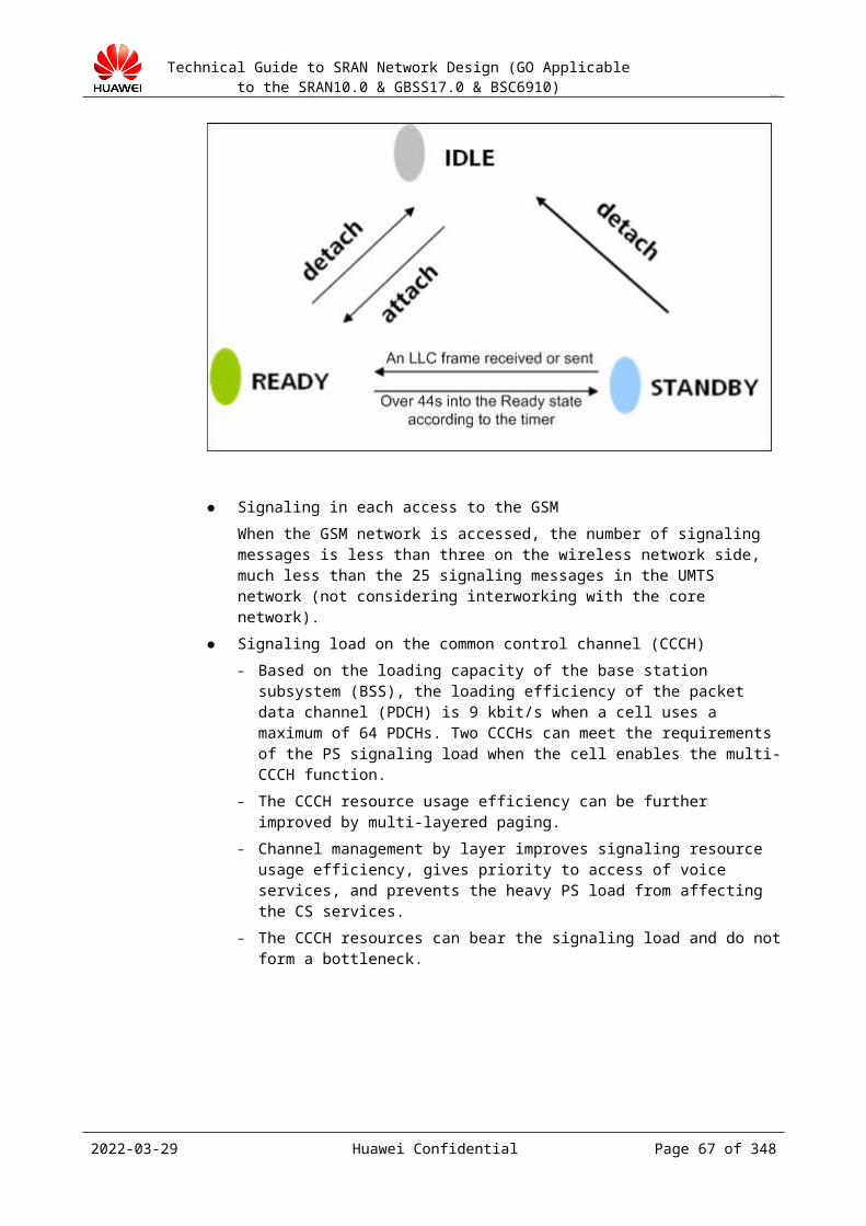
Technical Guide to SRAN Network Design (GO Applicable to the SRAN10.0 & GBSS17.0 & BSC6910)
CONFIDENTIAL
needs to be configured on the bearer plane.
LAG protection is configured for intra-board ports.
Low maintenance cost: The configuration is simple. Expansion can be easily implemented. The data path is clear.
High adaptability: This scheme has no special requirements on network device configuration.
13.1.2 Technical SpecificationsTable 13-1 Technical specifications
Fault Detection
Detection on the Physical Layer
BFD(100 ms x 3)
ARP(300 ms x 3)
Switchover ARP Message Sending
Total
Port Failure
Best: 300 msWorst: 600 ms
Best: 200 msWorst: 300 ms
Best: 6 secondsWorst: 9 seconds
Best: 100 msWorst: 1 second
Immediate transmission
Generally, it is shorter than 1 second.
Board Failure
The fault detection duration varies with the component where the fault occurs.
NA Best: 100 msWorst: 2 seconds
Immediate transmission
Generally, it is shorter than 3 seconds.
Remote Failure
Same as local fault detection
Note: The switchover duration is related to the number of routes, number of IP paths/SCTP links, and CPU usage of the interface board/SCU.
2023-04-22 Huawei Confidential Page 67 of 258

Technical Guide to SRAN Network Design (GO Applicable to the SRAN10.0 & GBSS17.0 & BSC6910)
CONFIDENTIAL
These specifications are internally used. Do not promise these to the customer unless it is necessary.
There are multiple detection modes. The actual switchover duration is determined by the quickest detection mode.
13.1.3 Technical Description1. Networking schemes in GBSS15.0:
− Pool of independent interface boards: An IP pool is added to a network that has independent dual-active interface boards.
− Pool of dual-active ports of active/standby boards: An IP pool is added to a network that has load-sharing ports and active/standby boards.
− Pool of active/standby boards+manual active/standby LAGs: It is an alternative for the solution of active/standby boards+active /standby ports. Networking changes are invisible to customers, but only internal configuration varies with flexible change. Furthermore, the reliability of the IP pool is improved and use this scheme on the A interface.
2. Principle description of active/standby boards+manual active/standby LAGsManual active/standby LAGs are adopted on active/standby boards. Link aggregation means to aggregate multiple physical links of the active and standby boards to a logical link, thereby generating an LAG. The LAG can increase bandwidth, improve transmission reliability, and transmit data streams of users over multiple links at the same time. Therefore, if an Ethernet port in an LAG is faulty, services are not interrupted. The BSC supports 1:1 active/standby link mode. If the active link is available, it sends and receives data. If the active link is faulty, the standby link takes over the data sending and receiving from the active link. This is known as a port active/standby mode based on link aggregation. In port active/standby mode, the active port transmits and receives data, and the standby port is generally not used or is used only for link detection. In addition, the active/standby port can be inconsistent with the active/standby board. That is, the active port can be on the active board or standby board.
Figure 13-1 describes the port switchover.
Figure 13-1 Port switchover
As shown in Figure 13-1, after switchover, active and standby boards remain unchanged. Port 0 of the active and standby boards are switched over. IP1 moves to port 0 in the standby board.
Figure 13-2 describes the board switchover.
2023-04-22 Huawei Confidential Page 68 of 258

Technical Guide to SRAN Network Design (GO Applicable to the SRAN10.0 & GBSS17.0 & BSC6910)
CONFIDENTIAL
Figure 13-2 Board switchover
Use networking based on active/standby boards, manual active/standby LAG, Layer-3 networking, router VRRP, and device IP for communication.
Typical configuration:
Device IP address: The active and standby boards share the same device IP address, and the default IP subnet mask is 32-bit subnet mask, which cannot be configured.
ETHIP: Each port is configured with an IP address, and uses the 29-bit subnet mask. Different ports belong to different network segments.
If ARP detection is not enabled on the standby port, generally no IP address is configured.
Recommended detection mode: Dual BFD detection on the active port. In this mode, the destination addresses are the port IP addresses corresponding to the two routers.
In the ARP detection on the standby port, the destination addresses are the VRRP IP addresses of the two routers.
2023-04-22 Huawei Confidential Page 69 of 258

Technical Guide to SRAN Network Design (GO Applicable to the SRAN10.0 & GBSS17.0 & BSC6910)
CONFIDENTIAL
14 Optical Interface MSP
This chapter describes the optical interface (STM-1 interworking design).
14.1 MSP Design GuideOptical interface interworking mainly describes the optical interface boards on the BSC side and the directly connected optical interface NEs (including the design of interworking between transmission devices).
14.1.1 STM-1 Tributary Mode SelectionFor channelized optical interfaces, the ITU standard does not clearly specify the mode in which timeslots are sequenced in the VC-4. Therefore, the VC-12 numbering rules in the VC-4 of different manufacturers are different. Three modes are available based on the numbering rules:
Huawei mode: In this mode, numbering is implemented based on timeslot numbers, and this mode is known as the sequence-based mode. The VC-12 is numbered based on TUG-3, then based on TUG-2, and finally based on TU-12.
Lucent mode: In this mode, numbering is implemented based on line numbers, and this mode is known as the insertion mode. The VC-12 is numbered based on TU-12, then based on TUG-2, and finally based on TUG-3.
Alcatel Mode: This mode is seldom used. In this mode, the VC-12 is numbered based on TUG-2, then based on TU-12, and finally based on TUG-3.
The optical interface of the BSC supports the preceding modes. In the case of interworking with network devices, find out the mode used at the peer end, and then configure the mode at the local end accordingly.
In addition, the VC-12 numbers of network devices start from 1 generally, and the E1T1 numbers of BSCs start from 0. Therefore, the E1T1 number on the BSC is not the same as the VC-12 number of the network device even if the numbering modes are the same. Instead, E1T1 number = VC-12 number – 1.
14.1.2 MSP Mode SelectionBy default, use the MSP 1+1 single-end non-recovery mode.
2023-04-22 Huawei Confidential Page 70 of 258
Technical Guide to SRAN Network Design (GO Applicable to the SRAN10.0 & GBSS17.0 & BSC6910)
CONFIDENTIAL
Table 14-1 MSP advantages and disadvantages
Solution Advantage Disadvantage Selection Principle (Sub-Scenario)
MSP 1+1 single-end non-recovery mode
Negotiation between the two ends is not required, and the compatibility is high.The switchover speed is high.The self-healing rate is high when multi-point faults occur.
A number of boards/backplanes of Huawei's BSC do not support the single-end mode.The paths in the two directions are inconsistent, and the implementation is complicated.
It is the default mode and is promoted.
MSP 1+1 double-end non-recovery mode
Negotiation between the two ends is required. The paths in the two directions must be the same for easy understanding and fault location.
Negotiation between the two ends is required, and protocol compatibility is required.
The boards/backplanes that do not support the 1+1 single-end mode use this mode.
The remote device or the customer requires this mode.
MSP 1:1 double-end recovery mode
The remote device does not support MSP 1+1 protection and only supports 1:1 protection.
14.1.3 Parameter ConfigurationTable 14-1 J0, J1, and J2 configuration
Length Mode (Byte)
Sending Receiving Selection Principle
16 The user can enter 15 bytes (the most significant bit cannot be 1), and the first byte is automatically generated (15-byte CRC7 check value, the most significant bit is 1). Then, the bytes are sent.
The receiving end adopts the same algorithm for comparison.
It is the standard mode and promoted by default. The detailed contents are negotiated with the remote end. The default SBS 155 is converted into hexadecimal 0X534253203135352020202020202020.
1 The single bytes set by the user are sent consecutively.
The bytes are checked one by one.
The remote end does not support the 16-byte mode. The detailed contents are negotiated with the remote end.
2023-04-22 Huawei Confidential Page 71 of 258
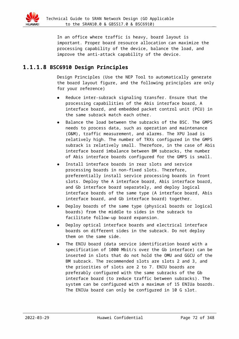
Technical Guide to SRAN Network Design (GO Applicable to the SRAN10.0 & GBSS17.0 & BSC6910)
CONFIDENTIAL
Length Mode (Byte)
Sending Receiving Selection Principle
64 The user can enter 62 bytes (0D0A cannot be present), and the last two bytes 0D0A are automatically generated. Then, the bytes are sent.
The receiving end adopts the same algorithm for comparison.
The remote end does not support the 16-byte mode. The detailed contents are negotiated with the remote end.
NULL All zeros without a format are sent consecutively.
A check is not performed.
The remote configuration cannot be known, or the formats at the two ends do not match.
The J2 of the AOUa and POUa does not support the 1-byte mode.If all zeros are received, no alarm is generated regardless of the format set at the local end.If the number of bytes/characters that the user enters is smaller than the required number, zeros or spaces are padded automatically (this can be configured by running Set OPT: JAUTOADD=ZERO/SPACE;). By default, spaces are padded. In interworking, ensure that the padding modes (ZERO/SPACE) at the two ends are the same.In NULL mode, the J byte does not provide the continuity check function and do not use it as the default configuration.Two configuration modes, that is, the character mode and the hexadecimal number mode, are available. Use the character mode because it is clear and not prone to errors.
14.1.4 S1 ConfigurationThe S1 byte is in the first column and the ninth row in MSOH of the SDH frame structure. The least significant four bits (bits 5 to 8) transmit the synchronization status information (SSM). Generally, the S1 byte refers to the least significant four bits. The most significant four bits are reserved. Huawei network devices expand the most significant four bits so that they can be used to transmit the clock ID.
Table 14-1 describes the definition of the S1 in G.707. The larger value indicates the lower clock quality.
Table 14-1 Definition of the S1 in G.707
Quality Level
San1, San2, San3, and San4
Synchronization Quality Level
0 0000 The quality is unknown (on the existing synchronization network).
2 0010 G.811 recommended clock
4 0100 SSU-A (G.812 transit exchange)
8 1000 SSU-B (G.812 local office)
11 1011 Synchronous equipment timing source (SETS)
2023-04-22 Huawei Confidential Page 72 of 258
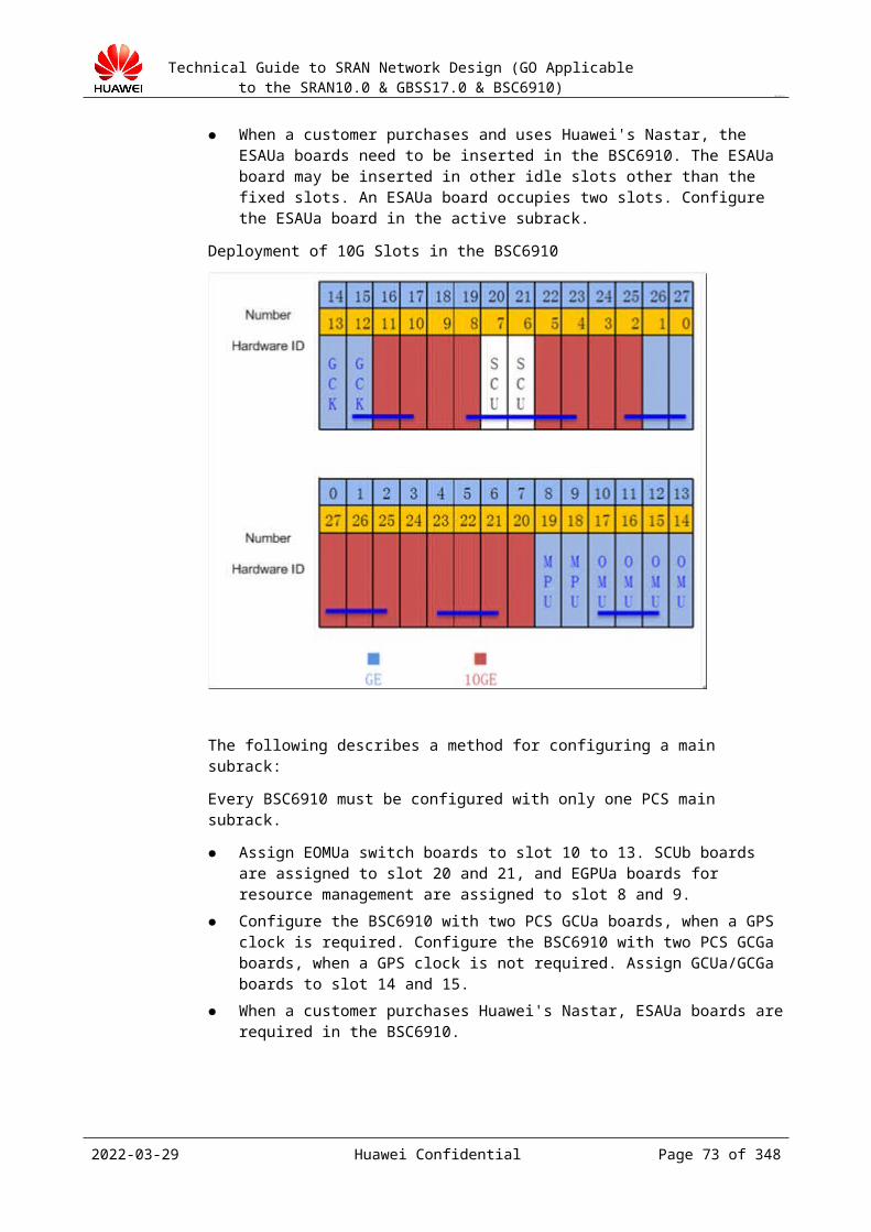
Technical Guide to SRAN Network Design (GO Applicable to the SRAN10.0 & GBSS17.0 & BSC6910)
CONFIDENTIAL
Quality Level
San1, San2, San3, and San4
Synchronization Quality Level
15 1111 Synchronization is unavailable.
The requirement for the clock of the BSC is stratum 3 and category A. Generally, the clock is obtained from the optical interface on the core network side. The BSC selects the clock based on the configured priority and does not process the S1 byte sent by the remote end of the optical interface.
The synchronous digital hierarchy (SDH) network of the Iub/Abis interface possesses its own clock and seldom obtains the clock from the BSC. In special cases, for example, the SDH network is the small-scale network dedicated for BTS backhaul, the SDH may trace the clock of the BSC. That is, the optical interface of the BSC seldom works as the clock source of the SDH devices.
Conclusion:
Set S1 to the default value 11 on the BSC, that is, the SETS. The BSC does not have a requirement for the S1 byte of the remote device.
14.1.5 C2 ConfigurationOn the BSC, the C2 byte does not need to be configured by the user but is determined by the board application type. If the interface is a channelized optical interface, the C2 byte is 0X02 (TUG structure); if the interface is a non-channelized optical interface, the C2 byte can be 0X13 (ATM mapping) or 0X16 (PPP Mapping). Table 14-1 lists the details of the C2 configuration.
Table 14-1 Details of the C2 configuration
Board Function C2 Value C2 Interpretation
POUc TDM+FR 0X02 TUG structure
It is required that the remote configuration be the same as the local configuration.
14.1.6 MSP Support Capabilities of BoardsTable 14-1 describes the MSP support capabilities of boards.
Table 14-1 MSP support capabilities of the boards of the BSC
Board Function MSP 1:1 MSP 1+1 single-end
MSP 1+1 double-end
Remarks
POUc TDM+FR Y Y(*) Y It supports the single-end mode only after it is inserted in the new backplane.
2023-04-22 Huawei Confidential Page 73 of 258
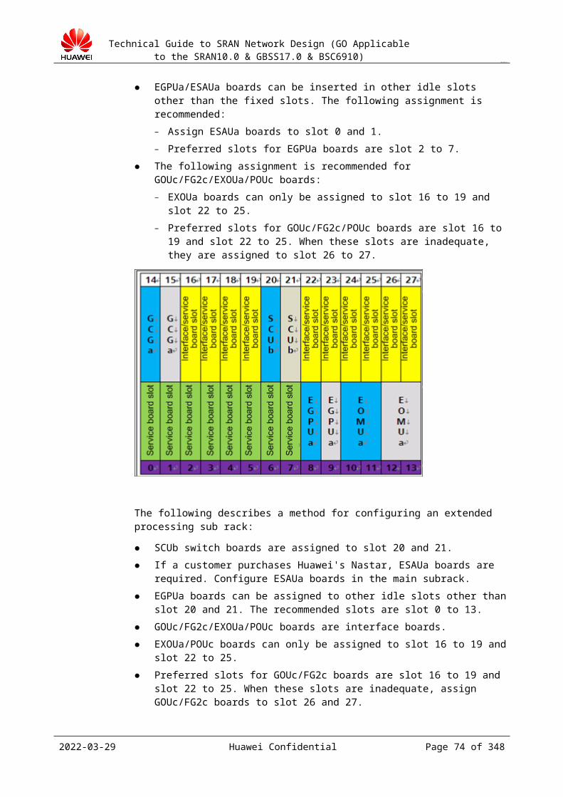
Technical Guide to SRAN Network Design (GO Applicable to the SRAN10.0 & GBSS17.0 & BSC6910)
CONFIDENTIAL
The new backplane refers to the backplane whose version is VER.C or later. The backplanes in the subracks delivered after about April 2008 are new backplanes.
14.2 MSP Technical DescriptionTechnical Description of the BSC Optical Interfaces
Framing mode
In optical interface interworking, three framing modes, that is, Huawei mode, Lucent mode, and Alcatel mode, are available. The names of the three modes are different from the names that partners use. This makes the communication between the technical personnel difficult for interworking negotiation. Therefore, the following describes the three modes and provides a reference for the communication between technical personnel.
Three SDH optical interface framing modes are available. They are Huawei mode (X increments first, then Y, and finally Z), Lucent mode (Z increments first, then Y, and finally X), and Alcatel mode (Y increments first, then Z, and finally X). The arrangement of the 63 PCMs on the optical interface varies with the framing mode. However, the first E1s in the three modes are the same.
For details, see Table 14-1.
2023-04-22 Huawei Confidential Page 74 of 258
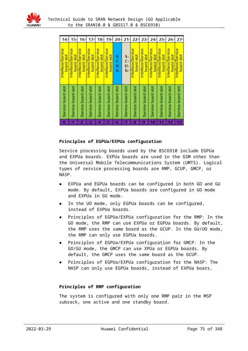
Technical Guide to SRAN Network Design (GO Applicable to the SRAN10.0 & GBSS17.0 & BSC6910)
CONFIDENTIAL
Table 14-1 Framing mode comparison
2023-04-22 Huawei Confidential Page 75 of 258

Technical Guide to SRAN Network Design (GO Applicable to the SRAN10.0 & GBSS17.0 & BSC6910)
CONFIDENTIAL
HuaweiModeCodes
X Y ZLucentModeCodes
ALCATEModeCodes
1 1 1 1 1 14 1 2 1 4 27 1 3 1 7 3
10 1 4 1 10 413 1 5 1 13 516 1 6 1 16 619 1 7 1 19 722 1 1 2 2 825 1 2 2 5 928 1 3 2 8 1031 1 4 2 11 1134 1 5 2 14 1237 1 6 2 17 1340 1 7 2 20 1443 1 1 3 3 1546 1 2 3 6 1649 1 3 3 9 1752 1 4 3 12 1855 1 5 3 15 1958 1 6 3 18 2061 1 7 3 21 212 2 1 1 22 225 2 2 1 25 238 2 3 1 28 24
11 2 4 1 31 2514 2 5 1 34 2617 2 6 1 37 2720 2 7 1 40 2823 2 1 2 23 2926 2 2 2 26 3029 2 3 2 29 3132 2 4 2 32 3235 2 5 2 35 3338 2 6 2 38 3441 2 7 2 41 3544 2 1 3 24 3647 2 2 3 27 3750 2 3 3 30 3853 2 4 3 33 3956 2 5 3 36 4059 2 6 3 39 4162 2 7 3 42 423 3 1 1 43 436 3 2 1 46 449 3 3 1 49 45
12 3 4 1 52 4615 3 5 1 55 4718 3 6 1 58 4821 3 7 1 61 4924 3 1 2 44 5027 3 2 2 47 5130 3 3 2 50 5233 3 4 2 53 5336 3 5 2 56 5439 3 6 2 59 5542 3 7 2 62 5645 3 1 3 45 5748 3 2 3 48 5851 3 3 3 51 5954 3 4 3 54 6057 3 5 3 57 61
2023-04-22 Huawei Confidential Page 76 of 258
Technical Guide to SRAN Network Design (GO Applicable to the SRAN10.0 & GBSS17.0 & BSC6910)
CONFIDENTIAL
Names and description of the optical interface interworking parameters:
Table 14-2 Optical interface interworking parameters
Parameter Name
Recommended Value
Description
Tributary Numbering
Negotiated with the peer end
It indicates the tributary arrangement sequence in an SDH frame. Optional modes: Lucent mode, Huawei mode, and Alcatel mode.
J0 trace mismatch alarm switch
Negotiated with the peer end
It indicates whether RTIM is reported if TX J0 Byte (Hexadecimal, Character String) or Expect RX J0 Byte (Hexadecimal, Character String) on both ends are inconsistent in optical interface interworking. Optional values: YES and NO.
J0 Mode Negotiated with the peer end
It indicates the maximum length of TX J0 Byte (Hexadecimal, Character String) and Expect RX J0 Byte (Hexadecimal, Character String).The J0 byte lengths of the optical interface devices provided by different manufacturers are different. Therefore, the maximum length of TX J0 Byte (Hexadecimal, Character String) and Expect RX J0 Byte (Hexadecimal, Character String) can be adjusted so that Huawei's device can interwork with the optical interface devices of other manufacturers and can be compatible with the earlier versions.The setting of this parameter must be consistent with the corresponding parameter on the peer optical interface device.
TX J0 Byte (Hexadecimal, Character String)
Negotiated with the peer end
This byte is used to repeatedly send the segment access point identifier so that the receiving end can determine based on this byte that the receiving end and the specified sending end are in the continuous connection state. The value is a character string of 0 to 15 characters.
Expect RX J0 Byte (Hexadecimal, Character String)
Negotiated with the peer end
This byte is used to repeatedly send the segment access point identifier so that the receiving end can determine based on this byte that the receiving end and the specified sending end are in the continuous connection state.The value is a character string of 0 to 15 characters.
J1 trace mismatch alarm switch
Negotiated with the peer end
It indicates whether HPTIM is reported if TX J1 Byte (Hexadecimal, Character String) or Expect RX J1 Byte (Hexadecimal, Character String) on both ends are inconsistent in optical interface interworking.
2023-04-22 Huawei Confidential Page 77 of 258

Technical Guide to SRAN Network Design (GO Applicable to the SRAN10.0 & GBSS17.0 & BSC6910)
CONFIDENTIAL
Parameter Name
Recommended Value
Description
J1Mode Negotiated with the peer end
It indicates the maximum length of TX J1 Byte (Hexadecimal, Character String) and Expect RX J1 Byte (Hexadecimal, Character String).The J1 byte lengths of the optical interface devices provided by different manufacturers are different. Therefore, the maximum length of TX J1 Byte (Hexadecimal, Character String) and Expect RX J1 Byte (Hexadecimal, Character String) can be adjusted so that Huawei's device can interwork with the optical interface devices of other manufacturers and can be compatible with the earlier versions.The setting of this parameter must be consistent with the corresponding parameter on the peer optical interface device.The optional lengths are 1 byte, 16 bytes, and 64 bytes.
TX J1 Byte (Hexadecimal, Character String)
Negotiated with the peer end
The J1 byte is used to repeatedly send the higher order path access point identifier so that the receiving end of the path can determine based on this byte that the receiving end and the specified sending end are in the continuous connection (the path is continuously connected) state.The value is a character string of 0 to 15 characters.
Expect RX J1 Byte (Hexadecimal, Character String)
Negotiated with the peer end
The J1 byte is used to repeatedly send the higher order path access point identifier so that the receiving end of the path can determine based on this byte that the receiving end and the specified sending end are in the continuous connection (the path is continuously connected) state. The value is a character string of 0 to 15 characters.
Set TX S1 Byte Negotiated with the peer end
It indicates whether the S1 byte is enabled. Optional values: YES and NO.
TX S1 Byte Negotiated with the peer end
It indicates the synchronization state byte. It is a character string of 0 to 15 characters.
2023-04-22 Huawei Confidential Page 78 of 258

Technical Guide to SRAN Network Design (GO Applicable to the SRAN10.0 & GBSS17.0 & BSC6910)
CONFIDENTIAL
Parameter Name
Recommended Value
Description
TX Frame Format
Negotiated with the peer end
In E1 working mode, only DOUBLE_FRAME and CRC4_MULTIFRAME are supported.In T1 working mode, only SUPER_FRAME and EXTENDED_SUPER_FRAME are supported.
RX Frame Format
Negotiated with the peer end
In E1 working mode, only DOUBLE_FRAME and CRC4_MULTIFRAME are supported.In T1 working mode, only SUPER_FRAME and EXTENDED_SUPER_FRAME are supported.
Configuration principles of the optical interface interworking data
If optical interface interworking is adopted, pay attention to the preceding parameters and configure the tributary numbering mode, J0, J1, J2, S1, frame format, and C2. The configuration principles are as follows:
Tributary Numbering on the BSC side must be consistent with Tributary Numbering on the MSC side.
TX J0 Byte (Hexadecimal, Character String) on the BSC side must be consistent with Expect RX J0 Byte (Hexadecimal, Character String) on the MSC side. Expect RX J0 Byte (Hexadecimal, Character String) on the BSC side must be consistent with TX J0 Byte (Hexadecimal, Character String) on the MSC side. Otherwise, ALM-20225 is generated.
TX J1 Byte (Hexadecimal, Character String) on the BSC side must be consistent with Expect RX J1 Byte (Hexadecimal, Character String) on the MSC side. Expect RX J1 Byte (Hexadecimal, Character String) on the BSC side must be consistent with TX J1 Byte (Hexadecimal, Character String) on the MSC side. Otherwise, ALM-20234 is generated.
TX J2 Byte (Hexadecimal, Character String) on the BSC side must be consistent with Expect RX J2 Byte (Hexadecimal, Character String) on the MSC side. Expect RX J2 Byte (Hexadecimal, Character String) on the BSC side must be consistent with TX J2 Byte (Hexadecimal, Character String) on the MSC side. Otherwise, ALM-20243 is generated.
The S1 synchronization state flag must be consistent with the flag on the MSC side, and the K1 and K2 parameters must be consistent with the parameters on the MSC side.
The sending and receiving framing formats on the two sides must be consistent.
The C2 parameter cannot be configured on the BSC6000. This parameter is set internally in the software, and the default value is 0x02. Therefore, check whether this parameter is set to 0x02 on the MSC side. If it cannot be confirmed, right-click the corresponding OIUa and select Query Interface Board Port State to check the C2 value sent by the remote end. The values on the two sides must be consistent. Otherwise, the interworking fails.
2023-04-22 Huawei Confidential Page 79 of 258

Technical Guide to SRAN Network Design (GO Applicable to the SRAN10.0 & GBSS17.0 & BSC6910)
CONFIDENTIAL
15 Detection Mechanism
15.1 Restrictions of the DesignTable 15-1 Restrictions of the fault detection mechanism of the BSC
2023-04-22 Huawei Confidential Page 80 of 258

Technical Guide to SRAN Network Design (GO Applicable to the SRAN10.0 & GBSS17.0 & BSC6910)
CONFIDENTIAL
Physical detection
Fixed: 300 ms x 2 times
ETH EFM Detection
It is associated with the port status. It can trigger an active/standby port switchover but cannot trigger a trunk switchover.The GB IP interface does not support ETH OAM.The EFM of the RNC requires that the PDU packet sending period of the remote end be the same as the period of the local end. Otherwise, negotiation fails. Set the period to one second.
ETH CFM Detection
The GB IP interface does not support ETH OAM.
PPP Status Detection
Default: 10 seconds x 5 times
ARP Detection
Default: 300 ms x 3 times16/board. The number of detections on a port is not limited. One port cannot perform BFD and ARP detections at the same time.The ARP automatically associates the next-hop route and sets the port as the key detection association port.The standby port supports only one ARP detection.The detected IP address of the standby port and the IP address of the active port can be in the same network segment.ARP does not support flow-based VLAN tagging and supports only next-hop-based tagging.
BFD Detection
Only the FE and GE ports support BFD, and the POS interface does not support BFD.16/board (SBFD+MBFD); 512/board (only the AIU). The number of detections on a port is not limited.Default: 30 ms x 3 timesOne IP address can perform either SBFD or ARP detection, but the two detections cannot be performed at the same time.Configure the MBFD associated IPRT and IP path. A 10-second delay is introduced in the case of path faults.The SBFD automatically associates the next-hop route and sets the port as the key detection association port.The active port can be associated with multiple detections (multiple ARP and BFD detections). The port becomes Down only if all the detections fail. The standby port does not support the BFD detection and supports only the ARP detection.The route and path can be associated with multiple detections (ARP/SBFD, MBFD, and ping). The route or path is considered faulty if any detection fails.The SBFD and MBFD distinguish sessions based on the source and destination IP addresses. They do not support multiple BFD detections on the same address pair or VLAN-based BFD.The MBFD uses port 4784 by default (stipulated in the new draft). After you enable the negotiation switch (by running SET BFDPROTOSW), the
2023-04-22 Huawei Confidential Page 81 of 258

Technical Guide to SRAN Network Design (GO Applicable to the SRAN10.0 & GBSS17.0 & BSC6910)
CONFIDENTIAL
local port number can be automatically adjusted to the same port number as the remote end. It can be used for the interworking with Huawei's router of an earlier version (the port number is 3784).
SCTP Detection
Default: MinRTO = 1000 ms; MaxRTO = 3000 ms; HB interval = 1000 ms; Association max retrains = 4; Path max retrans = 2
Table 15-2 Restrictions of the fault detection mechanism of the base station
NodeB Restrictions (RAN12.0) GBTS Restrictions (GBSS9.0)
Physical Detection
No smoothness on the upper layer NA
ETH EFM Detection
NA NA
ETH CFM Detection
NA NA
PPP Status Detection
NA NA
ARP Detection
Not supported Not supported
BFD Detection
The SBFD automatically associates the route whose next hop is the BFD destination address and does not associate with ports or other routes.The MBFD automatically associates the single-point route of the BFD destination address and does not associate with ports or other routes. The MBFD does not detect the standby route.In the active/standby route scenario, the applications with and without BFD are different. After the active route fails and the data is switched to the standby route, if the active route is recovered, then: 1) If the BFD is not configured, the priority of the active route is higher than that of the standby router; therefore, the data is switched back to the active route. 2) If the BFD is configured, the active route is available but the system still uses the standby route.
2 BFDs/boardDoes the SBFD automatically associate the route whose next hop is The BFD destination address?Enable the MBFD to associate the IP route.
SCTP Detection
Same as the RNC. Default: MinRTO = 1000 ms; MaxRTO = 3000 ms; HB interval = 1000 ms; Association max retrains = 4; Path max retrans = 2
N/A
2023-04-22 Huawei Confidential Page 82 of 258
Technical Guide to SRAN Network Design (GO Applicable to the SRAN10.0 & GBSS17.0 & BSC6910)
CONFIDENTIAL
15.2 BFD DetectionBFD definition:
The BFD can detect channel faults between forwarding engines with light load and quick response. Such faults include interface faults, data link faults, and forwarding engine faults. The BFD provides an independent mechanism to detect any media or protocol layer in real time. The detection time and payload ranges are wide, ensuring that only the BFD is used and avoiding conflicts with other detections.
BFD is short for bidirectional forwarding detection.
The BFD is implemented on the service layer of the system and the detection is specific to the connectivity for service packet forwarding.
The BFD can be used on the top layer of any data protocol to detect multiple network layers.
The BFD can detect faults on any type of channel between systems.
The BFD completes detection in milliseconds. It can implement rapid detection and switchover in a short time and can help to locate link faults.
One port can enable either the ARP or BFD detection at a time.
Recommended commercial solution:
In the most recommended solution, the dual BFD detection is implemented on the active port, the ARP detection is implemented on the standby port, and associated objects are ports.
Enable two BFD sessions on the active port. One BFD session detects the physical IP address of the active router, and the other detects the physical IP address of the standby router. Set both BFDs to key detections, and to enable automatic switchover of the active/standby ports when two BFDs are interrupted simultaneously.
Enable one ARP probe session on the standby port to detect virtual IP addresses of the two VRRP routers.
If both BFD sessions on the active port detect a fault but the ARP probe on the standby port indicates no abnormality, the switchover between the active port and the standby port is triggered automatically.
2023-04-22 Huawei Confidential Page 83 of 258
Technical Guide to SRAN Network Design (GO Applicable to the SRAN10.0 & GBSS17.0 & BSC6910)
CONFIDENTIAL
Figure 15-1 Diagram of the promoted commercial solution
Application analysis:
The BFD application in the current VRRP networking is defective: If the BFD is enabled on the active and standby ports, the remote address in the BFD after the active and standby ports are switched over remains unchanged; therefore, the remote address must be a fixed virtual address. In VRRP networking, this address can only be a VRRP virtual address, but the VRRP address of Huawei's router does not support the BFD detection, and the routers of other suppliers may not support the BFD detection. Therefore, the VRRP virtual address mode cannot be used.
Hence, Huawei proposes the dual BFD detection solution. On the BSC side, two BFD detections are initiated on the active port, and the remote ends are the interface addresses of the two routers. Currently, the VLAN interface addresses are used for implementing solutions, such as VLAN separation. On the router side, the BFD is associated with static routes, and then static routes are introduced into the dynamic routing protocol to ensure rapid convergence of downlink routes.
The active port on the BSC side determines the status of the two BFD detections. The active port considers the link down only when the status of both BFD detections is Down. In this way, rapid switchover can be implemented. When the active port is normal, a fault on the standby port does not affect services; therefore, rapid detection and switchover are not required, and use the ARP detection.
Application scenario of the multi-hop BFD (do not use):
Generally, the intermediate network provides the dynamic routing protocol and rapid switchover mechanisms for protection. A service NE requires only the protection between the NE and the access router instead of the protection across the intermediate network. Therefore, the E2E multi-hop BFD is not required.
If the scale of the bearer network is large, the multi-hop BFD cannot be completed quickly, and increases the network load.
Therefore, the multi-hop BFD is used only in the following scenarios:
The redundant path is independent on the network. The network is not protected. The end-to-end detection is required.
The number of routers is small, and no dynamic routing protocol is used between routers.
2023-04-22 Huawei Confidential Page 84 of 258

Technical Guide to SRAN Network Design (GO Applicable to the SRAN10.0 & GBSS17.0 & BSC6910)
CONFIDENTIAL
The access router does not run the dynamic routing protocol.
One port can enable either the ARP or BFD detection at a time.
15.3 ARP DetectionCompared with the BFD detection, the ARP detection is slow and completed in seconds.
Any gateway can respond to ARP requests. Therefore, the ARP detection does not require support from the peer end. In the ARP detection, broadcast packets are used and only the FE/GE addresses in the same network segment can be detected. Generally, the BFD detection is preferred, and the ARP detection is seldom used.
The main scenarios of the ARP detection in the recommended networking solution are as follows:
When the dual BFD detection is configured on the active port, the standby port adopts the ARP detection.
The ARP detection is used independently.
The purpose of the ARP detection is to detect the connectivity of gateways. If the current networking mode is VRRP, the addresses detected in the ARP detection are VRRP virtual addresses.
One port can enable either the ARP or BFD detection at a time.
15.4 IP PM Detection Functions of IP PM
IP performance monitor (PM) is an IP transmission QoS detection solution. The IP transmission QoS detection is the basis for the RAN system to perform flow control and admission control.IP PM provides the following functions:− Detects the delay, jitter, and packet loss in IP transmission.− Obtains the packet loss and delay of all the IP paths of a logical port. Then, based on
a certain algorithm module, dynamically adjusts the bandwidth of the logical port. If the bandwidth is reduced, packet loss is reduced and the efficiency is improved. If the bandwidth is increased, the bandwidth usage is improved.
− Detects the IP path connectivity and uses alarms to report the detection result to users. Basic principles of IP PM
IP PM is similar to ATM OAM PM. Forward monitoring (FM) and backward reporting (BR) are used to detect the packet loss condition along the path. One end sends FM messages periodically to indicate the number of packets sent by this end. The period can be specified to an interval or the number of sent packets. After receiving the FM messages, the remote end replies with BR responses to report the number of received packets. Then, the transmitting end measures the packet loss condition based on the BR responses.The basic process is as follows:
2023-04-22 Huawei Confidential Page 85 of 258
Technical Guide to SRAN Network Design (GO Applicable to the SRAN10.0 & GBSS17.0 & BSC6910)
CONFIDENTIAL
When the PM initiator needs to start the PM function, the PM initiator sends an ACT frame to the PM receiver. After receiving the ACT frame, the PM receiver enables the BR function from the PM receiver to the PM initiator and replies the PM initiator with an ACT ACK frame. After receiving the ACT ACK frame, the PM initiator enables the FM function from the PM initiator to the PM receiver. Then, the PM initiator sends FM frames periodically to the PM receiver, and the PM receiver replies the PM initiator with BR frames after receiving the FM frames.To enable the bidirectional link QoS detection, set up PM sessions in the directions from A to B and from B to A.
Recommended IP PM solution on the BSC sideIf IP paths require the IP PM detection and statistics to monitor the link quality, enable IP PM.
For the multiple flows whose source and destination addresses are the same (for example, when the boards work in active/standby mode and the ports work in load-sharing mode), the detection data and subscriber data may travel along different paths, and therefore the IP PM result is not reliable. In this case, disable IP PM.Currently, only the Abis IP path supports IP PM. This function must be used with the BTS. Therefore, ensure that the versions of both ends support this function.GBSS14.0 supports only the BSC providing FE and BTS providing E1.
Requirements of IP PM for the transmission networkThe DSCP value cannot be modified on the transmission network.
Scenarios that require IP PMIn the scenario where the quality of an IP transmission link fluctuates a lot (for example, ADSL), use dynamic bandwidth adjustment for the logical interface. In this case, IP PM must be enabled so that the currently available bandwidth can be adjusted based on the detection result.Basic principle: The closed loop control system is used to eliminate packet loss in the BSC, and the output rate of the logical interface of a BTS cannot exceed the measured bottleneck bandwidth of the logical interface.The closed loop control system detects the jitter or packet loss ratio of a detected flow on the transmission link from the BSC to the BTS. When the jitter or packet loss ratio of the detected link is increased, the closed loop control system adjusts the output rate of the logical interface of the link to reduce the link load and relieve the link congestion.The adjustment of the rate of the logical interface inevitably affects the queue of the logical interface. If the queue threshold is reached, the system informs the radio service processing board of the queue congestion in back pressure mode. The service processing board reduces the pressure. IP PM closed loop adjustment is used externally and closed loop adjustment of congestion back pressure is used internally. In this way, end-to-end congestion avoidance is implemented externally and internally in a joint manner.
2023-04-22 Huawei Confidential Page 86 of 258

Technical Guide to SRAN Network Design (GO Applicable to the SRAN10.0 & GBSS17.0 & BSC6910)
CONFIDENTIAL
16 IP Interworking Design
This section describes the IP interworking design, including IP technical solutions, such as layer-2 and layer-3 networking design in IP networking, IP address planning, VLAN planning, and address planning for the maintenance channel, in IP RAN networking.
16.1 IP Planning on the BSC Side1. Description of the IP addresses of interface boards
Interface board FG2c/GOUc/EXOUa that supports Ethernet ports:Each interface board supports up to 16 device IP addresses (DEVIP, logical IP address in the board).Each port can be configured with one active Ethernet port address (ETHIP) and up to five ETHIPs (configured only for the active port in port backup). Each port being used must be configured with at least the active Ethernet address.
2. Restrictions of IP address planning− IP addresses are determined by the customer based on the actual network conditions
and belong to the A/B/C category. An IP address consists of a network segment and a host segment. The host segment cannot be all 0s or all 1s (when CIDR is used, the selected IP address cannot be an invalid address in the A/B/C category). The first byte of an IP address cannot be 0 or 127.
− The network segment of the planned IP address and the network segment of the BAM internal network address cannot partially or totally overlap.
− Device IP address: The network segment of a device IP address and the network segment of the BAM internal network address cannot partially or totally overlap. A device IP address cannot be the same as or in the same network segment as any configured IP address in the BSC (it can be an IP address of the Ethernet port or remote address of the SCTP link). The device IP addresses configured on the same BSC cannot be in the same subnet, and the device IP addresses configured for different interface boards cannot be the same. When the CBS or MDSP service uses a device IP address, other services (such as the SCTP link) cannot use this device IP address. When a service other than CBS and MDSP uses a device IP address, CBS or MDSP cannot use this device IP address. However, the services other than CBS and MDSP can share the same device IP address.
− ETHIP: The network segments of different Ethernet port IP addresses cannot partially or totally overlap. The network segments of the active and standby IP addresses of the
2023-04-22 Huawei Confidential Page 87 of 258

Technical Guide to SRAN Network Design (GO Applicable to the SRAN10.0 & GBSS17.0 & BSC6910)
CONFIDENTIAL
same port cannot partially or totally overlap. An Ethernet port IP address cannot be the same as or in the same network segment as any configured IP address in the BSC (it can be a device IP address).
3. Principles of IP address planning− On the BSC side, use the device IP communication mode. The default 32-bit and 29-
bit subnet masks are used for the device IP address and port IP address respectively.− In network segment planning, IP addresses must be sufficient, and consider
reservation for extensibility. Use the simplest possible configuration for the remote router.
− In IP layer-2 (FE) networking, the ETHIPs of the ports on the BSC interface board are in the same network segment as the FE port IP addresses of the BTS. Use port IP communication for the BTS. One BTS uses one port IP address. The signaling, services, and O&M share the same IP address. Whether an independent NE adopts separate O&M IP address and service IP address depends on whether the O&M and service are separated on the bearer network. If the O&M and service are separated on the bearer network, the NE adopts separate logical O&M IP address and service IP address.
− In IP layer-3 networking, the length of the subnet mask of the address on the BSC side is irrelevant to the number of BTSs but is determined by the number of required addresses. In this case, further network segment separation is required. For example, an ETHIP must be in the same network segment as its gateway. If the gateway uses only one IP address, two valid addresses are required, and 30-bit subnet masks can be used. If the gateway adopts VRRP, the gateway requires one virtual IP addresses and two real IP addresses, and 29-bit subnet masks can be used.
− The device IP addresses of interface boards are in different network segments. The 30-bit or 32-bit subnet mask can be used (the 32-bit subnet mask is 255.255.255.255). Use the 32-bit subnet mask.
− The addresses on the BTS side are planned independently. Same as in the layer-2 networking, the length of the subnet mask is determined by the number of BTSs in the same network segment.
16.2 IP Planning on the BTS SideThe IP address planning of the BTS is related to the IP address planning of the BSC. They need to be implemented jointly.
Device IP address: logical IP address of the BTS (DevIP)
Port IP address: port IP address of the TMU
The same IP address works for O&M, signaling, and services for the BTS. Generally, use the port IP address.
Principles of IP address planning
On the BTS side, use port IP communication. One BTS uses one IP address. In layer-2 networking, the port IP address of the BTS is in the same network segment as
the port IP address on the corresponding interface board on the BSC. In layer-3 networking, the port IP address of the BTS is in the same network segment as
the port IP address of the next-hop gateway.
2023-04-22 Huawei Confidential Page 88 of 258

Technical Guide to SRAN Network Design (GO Applicable to the SRAN10.0 & GBSS17.0 & BSC6910)
CONFIDENTIAL
16.3 Routing Design on the BSC SideIt is required in IP layer-3 networking. Routes are added on the interface board. Add a host route for each BTS, or configure a network segment route for the network segment where the BTS resides. Configure a network segment route.
16.4 Routing Design on the BTS SideThe principles are as follows:
In layer-3 networking, configure the route from the BTS to the corresponding interface on the BSC and the route from the BTS to the IP CLK server.
In layer-2 networking, a route is not required.
For IP routes based on the source IP address, the port sending packets and the gateway IP address are queried based on the source IP address in the IP packets. For static route configurations, if the routes have the same source IP address, mask, and priority but different next-hop IP addresses, the static routes form equivalent routes. Packet routes can forward packets based on the flows or packets, and Huawei radio devices support only flow-based route forwarding. The eNodeB source IP routes configure different priorities to achieve active and standby routes. However, route load balancing is not supported. The ADD SRCIPRT command is used to configure the routing entries.
If only one IP address is available on the eNodeB side, the next-hop IP addresses are the same, and there are multiple destination IP addresses on the peer end, eNodeB source IP routes are recommended to simplify the route configuration on the eNodeB side, as shown in the following figure.
Figure 16-1 Scenario where the eNodeB source IP route is recommended
If there are multiple IP addresses on the eNodeB side, the next-hop IP addresses are different, and there is only one destination IP address on the peer end, the eNodeB source IP routes are not recommended, as shown in the following figure.
2023-04-22 Huawei Confidential Page 89 of 258

Technical Guide to SRAN Network Design (GO Applicable to the SRAN10.0 & GBSS17.0 & BSC6910)
CONFIDENTIAL
Figure 16-2 Scenario where the eNodeB source IP route is not recommended
If there is only one IP address on the eNodeB side, the next-hop IP addresses are different, and there are multiple destination IP addresses on the peer end, the eNodeB source IP routes are not supported, as shown in the following figure.
Figure 16-3 Scenario where the eNodeB source IP route is not supported
16.5 VLAN DesignThe VLAN technology partitions a physical LAN into different broadcast domains (based on IEEE 802.1Q). The broadcast traffic in one VLAN is not forwarded to another VLAN. This prevents broadcast storm.
The VLAN technology increases the security because any two VLANs cannot visit each other in layer-2. A field in the VLAN tag indicates the priority. This can distinguish priorities in layer-2.
If the BSC is directly connected to the layer-2 interface of the router:
2023-04-22 Huawei Confidential Page 90 of 258

Technical Guide to SRAN Network Design (GO Applicable to the SRAN10.0 & GBSS17.0 & BSC6910)
CONFIDENTIAL
Generally, no tag is used if sub-interfaces are not used.
If sub-interfaces are used, VLAN tags are required by default. Sub-interfaces share the MAC address. The router cannot distinguish flows based on the MAC address or based on the IP addresses in the received IP packets (the IP address in an IP packet is the destination IP address but not the source IP address). Therefore, VLAN tags are required to distinguish flows.
Planning principles:
In principle, the VLAN tags are not added on both the BSC and BTS, but are added on the intermediate devices.
To make VLAN planning logically clear and simplify the configuration, use the number of BTSs that are connected to one board or one optical interface of the transmission device (for example, the OSN) at the level-1 convergence point (nearest to the BTS side) as the number of BTSs that belong to the same VLAN.
Generally, the proper number of BTSs recommended for one VLAN is 20 to 100. In VLAN planning, use VLAN values segment by segment. For example, 2G and 3G
services use VLAN values in different ranges, and different interfaces use different VLAN values. This facilitates follow-up management, maintenance, and expansion.
VLAN tags can be added based on the next hop or based on the service flow. Only VLAN tagging based on the next hop is supported. VLAN tags can be added on the transmission device side, as listed in Table 16-1.
Table 16-1 Specifications of the VLAN on the interface board
Single SubrackVLAN ID 8192
ETH board FG2c/FG2d GOUc/GOUd
EXOUa
VLAN /PORT 4094 4094 4094
VLAN /BOARD 4094 4094 4094
16.6 QoS DesignQoS requirements of interfaces for IP transmission:
Table 16-1 Abis IP bearer network QoS requirement
Abis IP
Delay (ms) Jitter (ms) Packet Loss Rate (%)
Suggestion Value
Max Value
Suggestion Value
Max Value
Suggestion Value
Max Value
< 15 ms < 40 ms < 8 ms < 15 ms < 0.05% < 0.1%
2023-04-22 Huawei Confidential Page 91 of 258
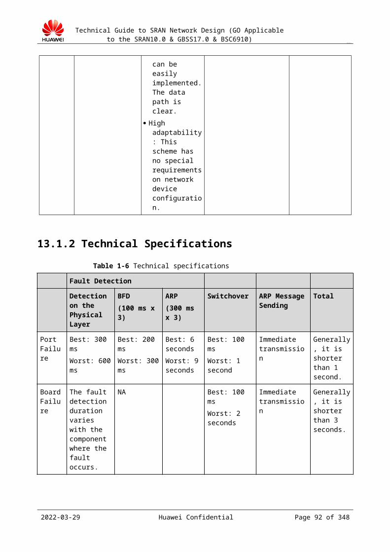
Technical Guide to SRAN Network Design (GO Applicable to the SRAN10.0 & GBSS17.0 & BSC6910)
CONFIDENTIAL
Table 16-2 A/Gb IP bearer network QoS requirement
A/Gb IP Delay (ms) Jitter (ms) Packet Loss Rate (%)
< 15 ms < 8 ms < 0.05%
Table 16-3 IPCLK and BTS/NodeB
Input Clock Precision Requirement
IPCLK < 0.016 ppm
BTS/NodeB < 0.05 ppm
QoS design principles:
For details, see the Configuration Recommendation of a specific version.
In GSM IP layer-3 network, different DSCP values are set for different services to ensure the QoS in IP transmission.
Basic principles:
The priority of signaling is the highest. The priority of the voice service is lower than that of signaling. The priority of the real-time data service is lower than that of the voice service. The priority of the non-real-time data service is lower than that of the real-time data
service.
The IP networks of different operators are different. If the number of DSCP values provided by an operator is smaller than the number of DSCP values recommended by Huawei, DSCP convergence can be implemented. For example, use the same DSCP for the voice service and the real-time data service.
2023-04-22 Huawei Confidential Page 92 of 258

Technical Guide to SRAN Network Design (GO Applicable to the SRAN10.0 & GBSS17.0 & BSC6910)
CONFIDENTIAL
17 Network Topology Design
17.1 Design Overview17.1.1 Purpose of the Design
The network topology design is based on the unit of area (or city). Within the unit, the topology details are designed. This is different from the design of the entire target network.
Design a detailed network topology figure that can help learn the connections between NEs, transmission type, and geographical location and can guide engineers through network construction.
Obtain information about the capacities, locations, and manufacturers of the interface NEs related to the MSC server, MGW, and SGSN, and analyze the possible networking risks, for example, whether the capacities of the MSC server and SGSN meet the requirements.
Design the network topology to optimize the resource usage and reduce the invalid load.
17.1.2 Input of the Design Information, such as geographical distribution and the number of NEs, area names,
equipment room names, and NE types Subscriber transmission information (transmission type, transmission quantity, and
transmission distribution)
17.2 Network Structure Design17.2.1 Design Guide
The network structure design is based on the unit of area. The input is the pre-sales target network. Details are designed. In the design, consider the geographical distribution of NEs, location relationship between the MSC server, MGW, BSC, and BTS, transmission types, and backbone transmission network.
Design principles:
2023-04-22 Huawei Confidential Page 93 of 258
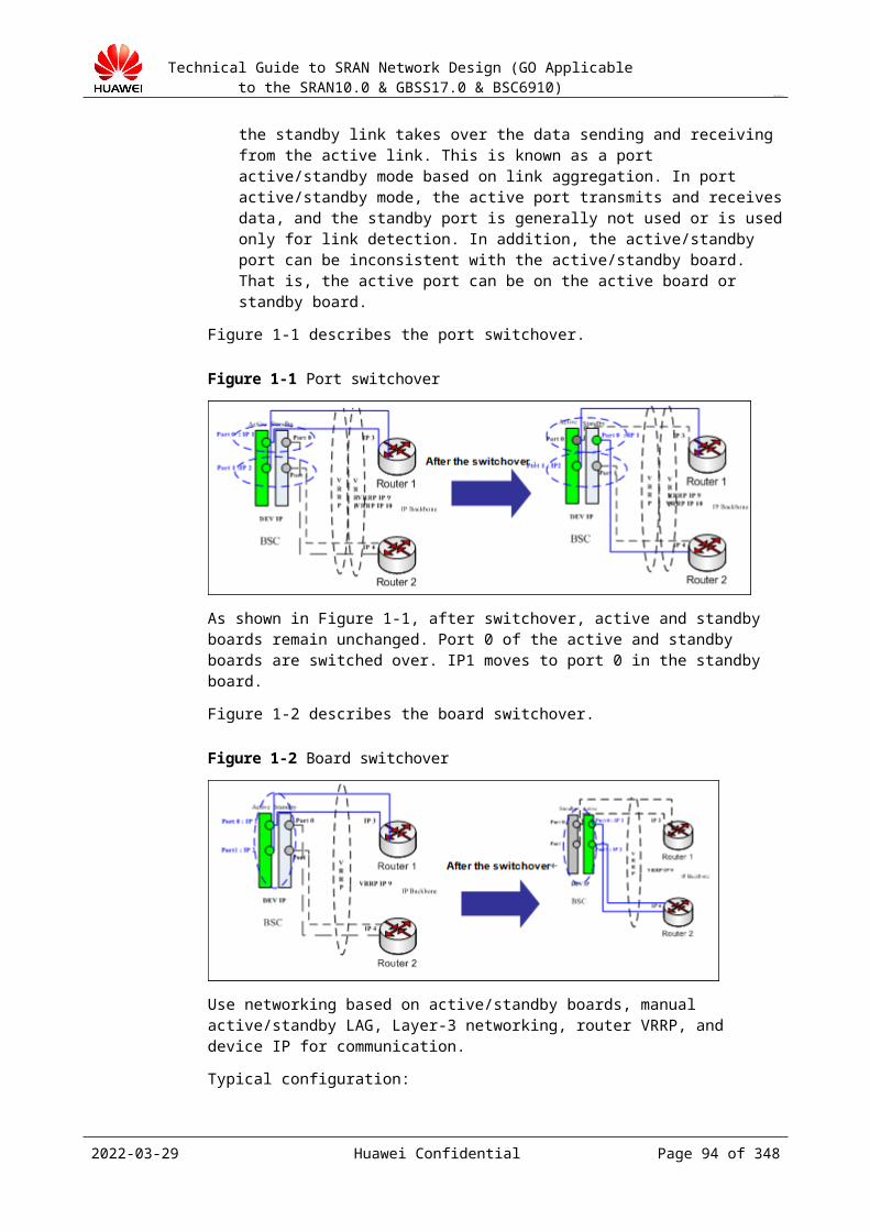
Technical Guide to SRAN Network Design (GO Applicable to the SRAN10.0 & GBSS17.0 & BSC6910)
CONFIDENTIAL
The transportation to the equipment room is convenient, and this facilitates maintenance. Select the equipment room where the power supply is stable and air conditioners/ESD floor are available.
Consider the distribution of existing transmission nodes when designing the BSC locations. Use the existing transmission nodes to save the investment.
Abis transmission cost control is important for the network where the number of sites is large. Ensure that the BSC location and Abis networking are good for transmission convergence.
Group the sites under the BSC based on geographical areas to facilitate LAC planning. Plan the BSCs in the same area in the same MSC server. Avoid discontinuous BSC
networking because it increases inter-MSC handovers, inter-MSC signaling load, and the configuration difficulty, and reduces the handover success ratio.
To improve the network security, connect one BSC to more than two MGWs that belong to the same MSC server (non-MSC Pool mode).
The SGSN capacity meets the data service requirements of the corresponding PCU. The networking design needs to collect the information about the capacity and manufacturer of the SGSN connected to the PCU.
Drawing requirements:
The networking diagram must be drawn based on the standard radio icons. The networking diagram must include the MSC server, MGW, BSC, and BTS and must
clearly show the connections between the NEs. The networking diagram must clearly mark the geographical homing areas of the NEs. Different types of lines must be used in the networking diagram to indicate different
transmission types.
17.2.2 Typical Networking
17.2.2.1 BSC/MGW Single-Homing NetworkingGenerally, one BSC is connected to one MGW and belongs to one MSC server. See Figure 17-1.
Figure 17-1 Networking of the BSC connected to a single MGW
2023-04-22 Huawei Confidential Page 94 of 258

Technical Guide to SRAN Network Design (GO Applicable to the SRAN10.0 & GBSS17.0 & BSC6910)
CONFIDENTIAL
17.2.2.2 BSC/MGW Multi-Homing NetworkingIf two or more MGWs are connected to the same MSC server, to improve the network reliability, assign the A interface transmission and signaling to different MGWs. Then, even if one MGW is faulty, the BSC can provide service continuously. See Figure 17-1.
If the MGW does not possess a signaling point and the SS7 signaling is transparently transmitted to the MSC server, you do not need to configure the signaling transfer point (STP) for SS7 on the BSC, and you need only to specify the STP of the MSC server as the destination STP.
If the MGW possesses signaling points, and the negotiation with the core network indicates that the STP needs to be configured for the BSC, configure multiple STPs (signaling points of the connected MGW) for the BSC.
BSC/MGW multi-homing requires the support of the core network and does not have requirements for the BSC. To use this networking mode, confirm that the core network supports this mode.
Advantage: The reliability is high and the networking is simple. This facilitates follow-up expansion and maintenance.
Figure 17-1 BSC/MGW multi-homing networking
17.2.2.3 MSC Pool NetworkingDifferent from traditional networking, in MSC Pool networking, one RNC/BSC can connect to multiple MSC servers at the same time. This implements the MSC-level backup mechanism. When one MSC server is faulty, the services of the BSC are automatically switched to another MSC server. This significantly improves the network reliability. After IP transmission is widely used, the MSC Pool planning is simplified a lot. In the past, physical interconnection is required; nowadays, routing configuration is used. It is predicted that the MSC Pool networking will be widely used after 2011.
Advantage: The reliability is high.
2023-04-22 Huawei Confidential Page 95 of 258
Technical Guide to SRAN Network Design (GO Applicable to the SRAN10.0 & GBSS17.0 & BSC6910)
CONFIDENTIAL
Disadvantage: The networking on the core network is complicated, and the design and implementation workload is heavy.
MSC Pool networking mode 1
The MGW implements the A-Flex function. The MGW implements the NNSF function. The BSC configuration does not need to be changed. For the BSC, the MSC servers in
the pool work as a large-capacity MSC server.
Use this mode. The BSC does not require special configuration. In addition, the reliability of the entire network is significantly improved.
Figure 17-1 MSC Pool networking mode 1
MSC Pool networking mode 2
The BSC implements the NNSF function. The BSCs are connected to multiple MGWs. The networking and expansion are complicated, and do not use this mode.
2023-04-22 Huawei Confidential Page 96 of 258
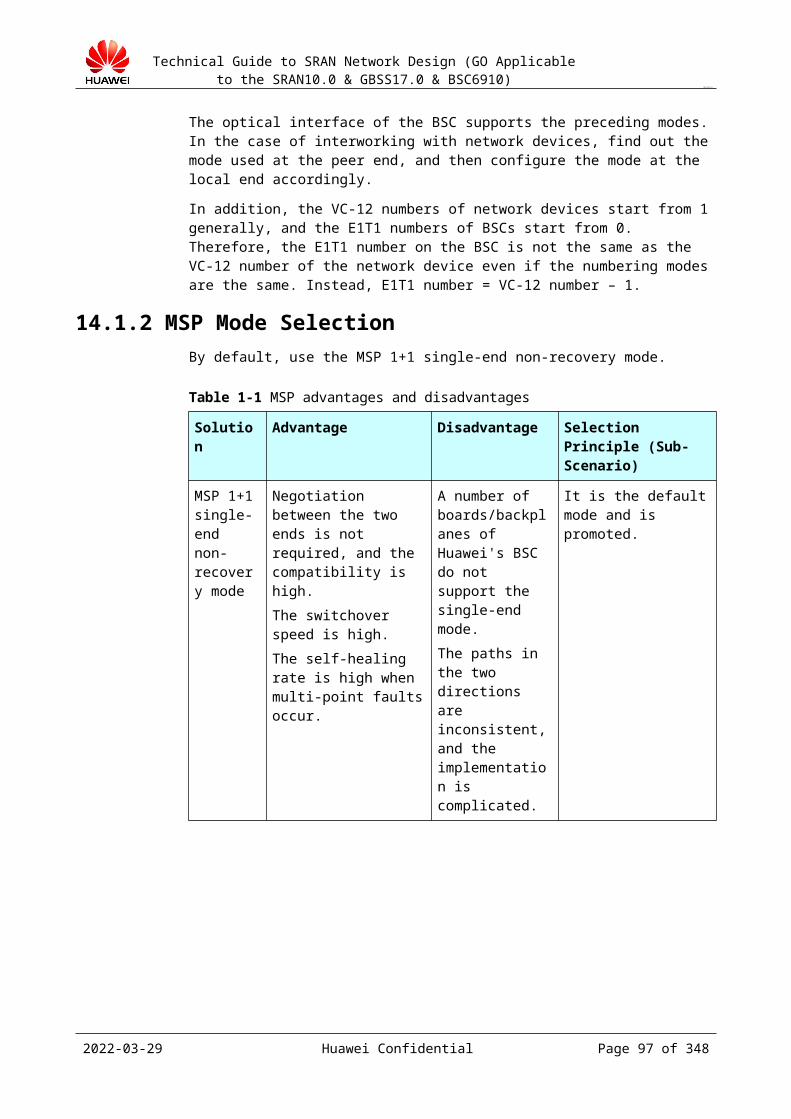
Technical Guide to SRAN Network Design (GO Applicable to the SRAN10.0 & GBSS17.0 & BSC6910)
CONFIDENTIAL
Figure 17-2 MSC Pool networking mode 2
17.2.2.4 SGSN Pool NetworkingThe SGSN pool is based on the Gb Flex technology. The SGSN pool area contains the area served by a group of SGSN nodes. In the pool area, multiple SGSNs run concurrently and share the service traffic in the pool area. If a single SGSN node is faulty, another SGSN in the pool can provide services. This significantly improves the network reliability.
Figure 17-1 shows the typical networking of the SGSN pool based on Gb over IP:
2023-04-22 Huawei Confidential Page 97 of 258
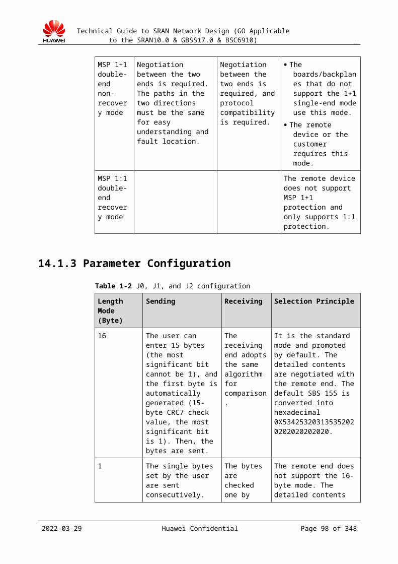
Technical Guide to SRAN Network Design (GO Applicable to the SRAN10.0 & GBSS17.0 & BSC6910)
CONFIDENTIAL
Figure 17-1 Typical networking of the SGSN pool
17.2.2.5 All-IP NetworkingThe all-IP networking saves the transmission cost a lot and provides better evolution capability to implement GU and GUL evolution. Generally, use layer-3 networking for all-IP networking. Figure 17-1 and Figure 17-2 show the typical networking diagrams.
2023-04-22 Huawei Confidential Page 98 of 258
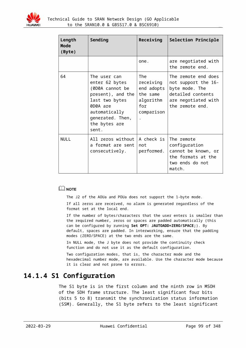
Technical Guide to SRAN Network Design (GO Applicable to the SRAN10.0 & GBSS17.0 & BSC6910)
CONFIDENTIAL
Figure 17-1 All-IP networking
Figure 17-2 Typical IP-based networking
17.2.2.6 Hybrid NetworkingThe common networking mode is A interface over IP+Abis interface over TDM, as shown in Figure 17-1.
2023-04-22 Huawei Confidential Page 99 of 258

Technical Guide to SRAN Network Design (GO Applicable to the SRAN10.0 & GBSS17.0 & BSC6910)
CONFIDENTIAL
Figure 17-1 Hybrid networking
17.2.2.7 Transmission Resource Pool NetworkingIf multiple A interface boards of the BSC form a transmission resource pool, the MGW can communicate with the BSC through any board in the pool. If an interface board in the pool is overloaded, the system automatically allocates the newly connected calls to other interface boards. In addition, the BSC implements the source IP-based route and IP-path-free configuration, in other words, if IP addresses on the MGW are added or modified, IP route and IP path configurations on the BSC do not need to be changed, thereby simplifying the configuration.
The SCTP links on the control plane are deployed on two different interface boards in the transmission resource pool by dual-homing to improve data protection on the control plane.
The transmission resource pool over the A interface can work in the following modes:
Mode 1: The A interface boards work in active/standby mode. Mode 2: The A interface boards work independently.
Mode 1 provides high reliability. When A interface boards are faulty, ongoing calls are not dropped. Mode 2 provides high board usage, but ongoing calls are disconnected once an interface board is faulty.
This solution requires a three-layer networking between the BSC and the MGW to ensure interconnection between the MGW and all interface boards of the BSC.
For details, see A Interface Transmission Pool. The transmission resource pool is used on the A interface over IP network. Figure 17-1 shows the logical networking of the transmission resource pool.
2023-04-22 Huawei Confidential Page 100 of 258
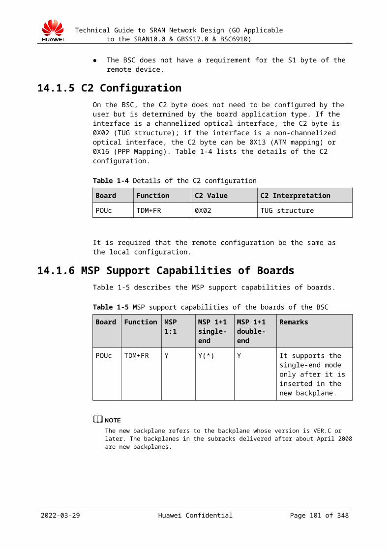
Technical Guide to SRAN Network Design (GO Applicable to the SRAN10.0 & GBSS17.0 & BSC6910)
CONFIDENTIAL
Figure 17-1 Logical networking of the transmission resource pool
As shown in Figure 17-2, two pairs of active/standby FG2c/GOUc boards form a pool. Each board is configured with a logical board IP (DEVIP) address as the service IP address. These device IP addresses form a service IP address pool. During a call setup, the BSC selects an IP address from the service IP address pool to carry the call in a way that ensures load balance.
Figure 17-2 Physical networking of the transmission pool with active/standby boards
As shown in Figure 17-3, four independent FG2c/GOUc boards form a pool. Each board is configured with a logical board IP (DEVIP) address as the service IP address to comprise a
2023-04-22 Huawei Confidential Page 101 of 258
Technical Guide to SRAN Network Design (GO Applicable to the SRAN10.0 & GBSS17.0 & BSC6910)
CONFIDENTIAL
service IP address pool. During a call setup, the BSC selects an IP address from the service IP address pool to carry the call in a way that ensures load balance. Use this networking.
Figure 17-3 Physical networking of the transmission pool with independent boards
In this networking mode, configure two or more ports for an interface board to form an LAG to avoid ongoing call drop in case of a port fault. Compared with the networking of transmission pool with active/standby boards, this networking has the following advantages and disadvantages: Advantages
− The maximum payload throughput rate and the connection capability of the interface board are doubled.
− There are no restrictions on the slot configuration of the active/standby board. Therefore, the interface boards can be evenly distributed to each frame.
− The interface board can be independently added. − The router configuration is simple, that is, no static routes with different levels of
priorities are required. Disadvantages: if the interface board is faulty, ongoing calls are dropped.
2023-04-22 Huawei Confidential Page 102 of 258

Technical Guide to SRAN Network Design (GO Applicable to the SRAN10.0 & GBSS17.0 & BSC6910)
CONFIDENTIAL
18 Reliability Design
18.1 Design Overview18.1.1 Purpose of the Design
The design is based on product features and transmission routes to improve the network reliability.
Design a detailed network topology figure that can help learn about the connections between NEs, transmission type, and geographical location.
18.1.2 Input of the Design Network structure diagram Transmission routing information
18.2 Network Reliability Design18.2.1 Design Guide
The reliability design of the radio network is based on the following:
Active/standby feature of boards Active/standby feature of links Active/standby feature of transmission resources MSC pool SGSN pool Flow control policy Device load balancing Proper data configuration
Design principles:
1. Implement the network reliability design based on the board active/standby feature of the product. For example, board active/standby feature and link active/standby feature of the A interface, Abis interface, and Gb interface.
2. Implement port protection on the transmission device to improve reliability. For example, if you need to improve reliability but do not want to increase investment in backbone transmission, you can implement transmission port backup by using the timeslot cross device on designed backbone transmission interfaces.
2023-04-22 Huawei Confidential Page 103 of 258

Technical Guide to SRAN Network Design (GO Applicable to the SRAN10.0 & GBSS17.0 & BSC6910)
CONFIDENTIAL
3. Design the networking structure to improve the network reliability. Use BSC/MGW cross networking, MSC pool networking, and SGSN pool networking.
4. Distribute transmission resources properly and use proper configuration principles to improve the network reliability. For example, distribute signaling and calls evenly to different routes to reduce node cross-connection and avoid concurrent service interruption.
5. Learn the port distribution of the remote device. Distribute the transmission resources of the same BSC to different interface boards to improve the network reliability.
18.2.2 Design Examples
18.2.2.1 Reliability of Active/standby Links on PortsBased on product features, active/standby links and active/standby boards of the A interface, Gb interface, and Abis interface can be implemented to improve the network reliability.
If the core network supports the active/standby configuration of the A interface, use the active/standby configuration function of the A interface of the BSC6910.
If the core network does not support the active/standby configuration of the A interface, the A interface board of the BSC6910 is configured to work in standalone mode.
For details about APS 1+1, see Figure 18-1.
Figure 18-1 Improving reliability by active/standby links on ports
2023-04-22 Huawei Confidential Page 104 of 258
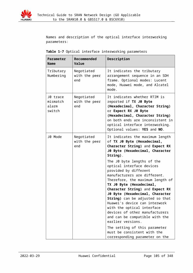
Technical Guide to SRAN Network Design (GO Applicable to the SRAN10.0 & GBSS17.0 & BSC6910)
CONFIDENTIAL
Figure 18-2 Reliability design of the Gb interface
18.2.2.2 Reliability of Load BalancingEvenly distribute BTSs, TRXs, and SS7 links to the modules of the BSC to balance the load between the modules. Balanced load can improve the anti-shock capability of the BSC in the case of burst traffic. The principles are as follows:
Evenly distribute BTSs and TRXs to the modules of the BSC. Evenly distribute SS7 links (with the same bandwidth) to the modules. If the traffic of a single BSC reaches 70% of the design specifications, the balance of
SS7 links, BTSs, and RSI links on different CPUs is adjusted to further design the load balancing. You can apply for R&D support.
18.2.2.3 Reliability of Data Configuration Evenly distribute SS7 links and bandwidth to the modules of the BSC. The minimum
number of SS7 links is 2. Configure SS7 links to different transmission resources and boards to reduce node cross-
connection and improve the network reliability. For example, configure SS7 links to different MGW boards, A interface boards, A
interface physical transmission channels, and backbone transmission channels.
18.2.2.4 Reliability of Multiple Transmission RoutesConfigure transmission routes to improve the reliability. Configure the transmission resources of the same NE to different transmission nodes and routes to reduce the possibility of service interruption caused by the faults in a single transmission node and to improve the network reliability. As shown in Figure 18-1, the GOUc of the BSC6910 provides four physical transmission links destined for the remote NEs through two CEs. This implements reliability of multiple transmission links and prevents service interruption caused by the faults in a single transmission node.
2023-04-22 Huawei Confidential Page 105 of 258

Technical Guide to SRAN Network Design (GO Applicable to the SRAN10.0 & GBSS17.0 & BSC6910)
CONFIDENTIAL
Figure 18-1 Reliability design of IP transmission routes
18.2.2.5 Reliability of the IP Networking VRRP TechnologyAs shown in Figure 18-1, in Gb over IP mode, the VRRP technology is used to implement the active/standby mechanism of the routers AR1 and AR2, and the active/standby Gb interface boards are configured for the BSC. In this manner, a reliable transmission route is established to improve the network reliability.
Figure 18-1 Reliability design of IP transmission routes
The VRRP protocol is used to dynamically select a master router from a group of VRRP routers and associate the router to a virtual router as the default gateway of the connected network segment.
The VRRP router that is selected to associate with the IP address of a virtual router is the master router. The master router forwards the packets destined for the virtual router.
If the master router is faulty, VRRP selects another VRRP router as the master router to forward the packets destined for the virtual router.
2023-04-22 Huawei Confidential Page 106 of 258
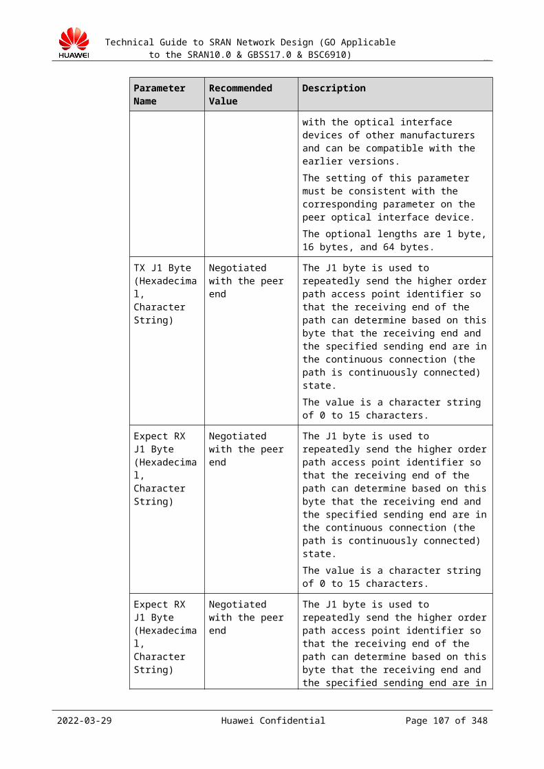
Technical Guide to SRAN Network Design (GO Applicable to the SRAN10.0 & GBSS17.0 & BSC6910)
CONFIDENTIAL
The advantage of VRRP is that the reliability of the default gateway is improved for the host.
In VRRP configuration, trunks must be configured between routers. At least two physical links must be configured, and the bandwidth needs to be twice higher than the service traffic.
18.2.2.6 SCTP Multi-Homing DesignIn A over IP mode, the M3UA SCTP multi-homing design implements highly reliable SS7 design. On the GBSS side, only the A interface supports the SCTP configuration. For details, see section 19.2.3 "SCTP Multi-Homing Design."
18.2.2.7 Reliability of BSC Multi-Homing (Connected to Multiple MGWs)
The BSC6910 supports the configuration of multiple DSPs and STPs. The transmission links of the A interface of the BSC are connected to two or more MGWs (the MGWs belong to the same MSC server). Then, if a single MGW is faulty, the services of the BSC are not interrupted. This improves the BSC reliability. Figure 18-1 shows the typical networking.
Figure 18-1 BSC/MGW multi-homing networking
18.2.2.8 Reliability Based on the MSC POOLFor details, see the GSM MSC Pool Network Design Guide.
In the traditional mobile communication network, one BSC is connected only to one MSC server. In the MSC pool network, one BSC can be connected to multiple MSC servers. Compared with the traditional network, the MSC pool network has the following advantages:
Load sharing: Multiple MSC servers share the network load to improve the resource usage of the entire core network and save the device investment.
Disaster tolerance: The MSC-level redundancy is implemented. If a single MSC server is faulty, the services of the BSC are not interrupted.
2023-04-22 Huawei Confidential Page 107 of 258
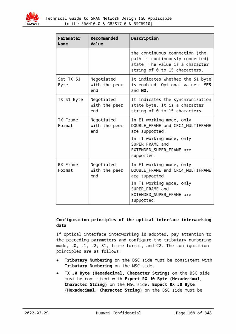
Technical Guide to SRAN Network Design (GO Applicable to the SRAN10.0 & GBSS17.0 & BSC6910)
CONFIDENTIAL
Inter-office location updates are reduced, the signaling traffic on the C/D interface is reduced, and the MSC capacity gain is obtained.
Inter-office handovers are reduced, and the quality of subscriber calls is improved.
In the office that requires high reliability, use the MSC pool solution. The commonly used networking solution is as follows:
The MGW implements the A-Flex function and NNSF function. The BSC configuration does not need to be changed. For the BSC, the MSC servers in the pool work as a large-capacity MSC server. Use this MSC pool networking mode because no special BSC configuration is required and the reliability of the entire network is improved.
Figure 18-1 MSC Pool networking mode 1
The BSC provides the NNSF function. BSCs are interconnected with multiple MGWs. Networking and capacity expansion are complicated. Use this networking mode for the IP networking.
2023-04-22 Huawei Confidential Page 108 of 258
Technical Guide to SRAN Network Design (GO Applicable to the SRAN10.0 & GBSS17.0 & BSC6910)
CONFIDENTIAL
Figure 18-2 MSC Pool networking mode 2
18.2.2.9 Reliability Based on the SGSN PoolThe SGSN pool is based on the Iu Flex technology. The SGSN pool area contains the area served by a group of SGSN nodes. In the pool area, multiple SGSNs run concurrently and share the service traffic in the pool area. If a single SGSN node is faulty, another SGSN in the pool can provide services. This improves the network reliability.
For details, see the GSM SGSN Pool Network Design Guide.
This solution can be used based only on Gb over IP.
Figure 18-1 shows the typical networking diagram.
2023-04-22 Huawei Confidential Page 109 of 258
Technical Guide to SRAN Network Design (GO Applicable to the SRAN10.0 & GBSS17.0 & BSC6910)
CONFIDENTIAL
Figure 18-1 Typical networking diagram of the SGSN pool
18.2.2.10 Reliability Based on Dynamic Load Balancing of A Interface Boards
Figure 18-1 shows the IP networking topology of A interface boards based on the dynamic loading balancing.
Figure 18-1 IP networking topology of A interface boards based on the dynamic loading balancing
If multiple A interface boards of the BSC form a transmission resource pool, the MGW can communicate with the BSC through any board in the pool. When the load of an interface board in the pool is high, the BSS automatically distributes calls to interface boards with light traffic. In addition, the BSC implements the free configurations on IP routes and IP paths. That is, when the IP address is added or modified on the MGW, the BSC does not need to change the configuration of the corresponding IP path or IP route. This simplifies the configurations.
2023-04-22 Huawei Confidential Page 110 of 258
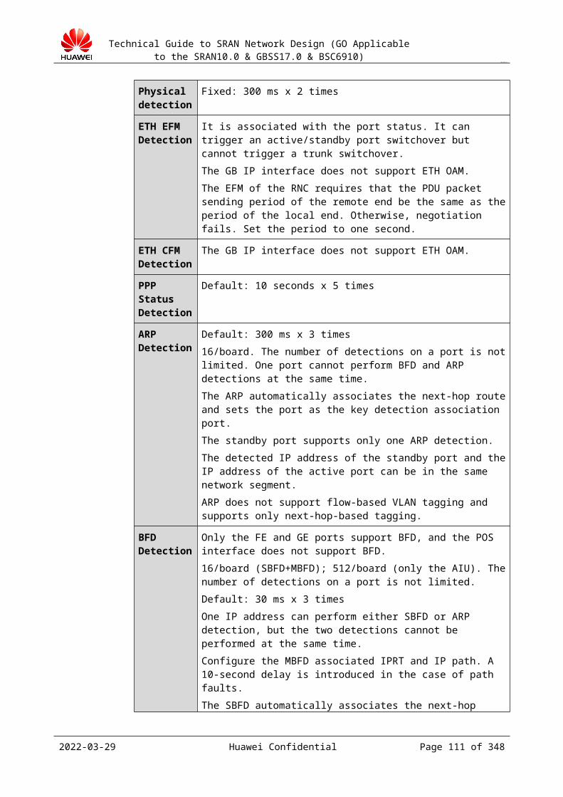
Technical Guide to SRAN Network Design (GO Applicable to the SRAN10.0 & GBSS17.0 & BSC6910)
CONFIDENTIAL
The SCTP links on the control plane are deployed on two different interface boards in the transmission resource pool by dual-homing.
The transmission resource pool over the A interface can work in the following modes: Mode 1: The A interface boards work in active/standby mode. Mode 2: The A interface boards work independently. Mode 1 provides high reliability. When A interface boards are faulty, ongoing calls are not dropped. Mode 2 provides high board usage, but ongoing calls are disconnected once an interface board is faulty.
This solution requires a three-layer networking between the BSC and the MGW to ensure interconnection between the MGW and all interface boards of the BSC.
OM ReliabilityThe OM reliability design of the BSS is implemented through the active/standby EOMU configurations and the active/standby EOMU port configurations. Figure 18-2 and Figure 18-3 show the typical networking modes.
Figure 18-2 Standalone EOMU
2023-04-22 Huawei Confidential Page 111 of 258
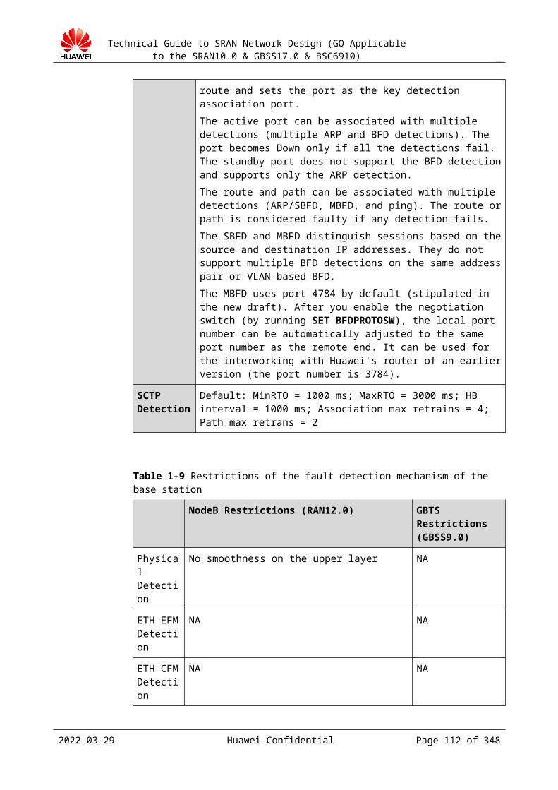
Technical Guide to SRAN Network Design (GO Applicable to the SRAN10.0 & GBSS17.0 & BSC6910)
CONFIDENTIAL
Figure 18-3 Dual EOMUs
Clock ReliabilityClock reliability of the BSC6910
The design of the clock system reliability of the BSC6910 is simple. This section describes the principle and reliability mechanism of the clock system for better communication with operators.
GCUa/GCGa boards provide clock information for the BSC6910 system. They are located at slots 14 and 15 of the GMPS subrack to form the active/standby relationship. Either GCUa boards or GCGa boards can be installed on the BSC6910 based on the clock type. GCGa boards have satellite cards and can obtain signals of GPS clock sources. On an all-IP network, the BSC does not need a clock.
Clock sources of the BSC6910 system are as follows:
Building Integrated Timing Supply System (BITS) clock External 8 kHz clock GPS clock
The GCUa/GCGa boards support plane input of the clock sources.
Clock signals provided by the BITS are transmitted to the GCUa/GCGa boards through panel interfaces.
Figure 18-4 shows the clock subsystem of the BSC6910.
2023-04-22 Huawei Confidential Page 112 of 258
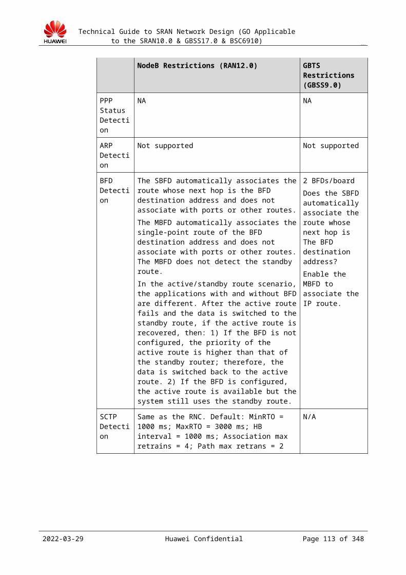
Technical Guide to SRAN Network Design (GO Applicable to the SRAN10.0 & GBSS17.0 & BSC6910)
CONFIDENTIAL
Figure 18-4 Clock subsystem of the BSC6910
Clock information generated by the GCUa/GCGa boards is processed as follows:
The clock information is sent to the SCUb board of the local subrack through the backplane and then the SCUb board of the local subrack sends the clock information to service boards in the subrack.
The clock information is sent to SCUb boards of GEPS subracks through plane interfaces and then the GSCU boards of the GEPS subracks send the clock information to service boards in the subrack.
The clock system of the BSC6910 has the following characteristics:
Clock holdover function: When external clocks are faulty, local free-run clocks can continue providing stable clocks for the system.
The clock system of the BSC adopts the digital phase-locked loops and reliable software phase-locked loops to ensure that the clock of the BSC is synchronized with clock reference sources.
The BSC clock adopts international standard layer-3 clocks to provide stable and reliable clock sources for the system.
The clock system provides complete display, alarm, and operation and maintenance functions. You can set internal parameters of the clock on the maintenance terminal.
If configured clock reference sources are lost, the system traces other available reference sources. If no clock sources are available and the system has traced other reference sources for 10 minutes, the system is in the holdover state. If the system does not detect that frequency deviation is great during this process, software phase-locked loops are
2023-04-22 Huawei Confidential Page 113 of 258
Technical Guide to SRAN Network Design (GO Applicable to the SRAN10.0 & GBSS17.0 & BSC6910)
CONFIDENTIAL
retained for 10 days and then the system is in the free-run state. Although the system provides high-precision holdover function, quick restoration of references sources is also required. In the synchronization networking (non-IP clock sources) mode, services are affected due to the free-run state. Therefore, time specifications of affected services cannot be determined.
Reliability of Ethernet Link AggregationIn link aggregation, multiple physical links are aggregated to form a logical link. Multiple links are aggregated to an LAG.
The Ethernet link aggregation can increase the bandwidth, improve transmission reliability, and ensures that traffic is distributed to different links for transmission. When an Ethernet port in the LAG is faulty, services are not interrupted.
The Ethernet link aggregation implemented by Huawei aims to:
Replace the active/standby port mode. The external networking of the manual active/standby LAG mode and the active/standby port mode are the same. The manual active/standby LAG networking mode apples to more scenarios and is more convenient to interwork with peer equipment. It supports flexible networking mode. For example, the active/standby LAG can be located on one board, but active/standby ports must be on active/standard boards respectively.
Reliability and check mechanism for the manual active/standby LAG networking mode and the active/standby port networking mode are the same.
If the active/standby board has multiple ports, enable multiple manual active/standby LAGs, which is the same as that of multiple active/standby ports. The local equipment does not need to interwork with peer equipment through the static LACP.
The Ethernet link aggregation matches the MRFD-210103 Link aggregation feature.
Application of the link aggregation
Typical application scenarios of link aggregation on the BSC side are as follows:
BSC belonging to two layer-2 transmission devices in the dual-homing mode BSC belonging to one layer-2 transmission device in the single-homing mode Inter-board link aggregation in the inter-board pool networking scenario Link aggregation on the BSC side and the interworking router adopting the VRRP
networking mode
BSC belonging to two layer-2 transmission devices in the dual-homing mode
As shown in Figure 18-5, two FE/GE links on the active/standby board of the BSC form an LAG and are respectively connected to two transmission devices, such as the Optical Switch Node (OSN)/Packet Transport Network (PTN) device. This LAG crosses two transmission devices.
2023-04-22 Huawei Confidential Page 114 of 258

Technical Guide to SRAN Network Design (GO Applicable to the SRAN10.0 & GBSS17.0 & BSC6910)
CONFIDENTIAL
Figure 18-5 BSC belonging to two layer-2 transmission devices in the dual-homing mode
The LAG that crosses two transmission devices is named Multi-Chassis Link Aggregation Group (MC-LAG) on the network side. Currently, the MC-LAG works in only the active/standby mode. Therefore, the working mode of the aggregation group on the BSC side must be set to the active/standby mode. In addition, the aggregation mode on the BSC side needs to be set to static aggregation. This ensures that the active/standby properties of links that transmission devices use to interwork with the BSC through the LACP protocol are consistent.
BSC belonging to one layer-2 transmission device in the single-homing mode
As shown in Figure 18-6, multiple FE/GE links on the active/standby board of the BSC form an aggregation group and are connected to one layer-2 transmission device.
Figure 18-6 BSC belonging to one layer-2 transmission device in the single-homing mode
In this application:
When an aggregation group works in the active/standby mode, the aggregation group ensures that links are reliable and the active/standby board on the BSC side ensures that boards are reliable.
When an aggregation group works in the load sharing mode, the aggregation group not only ensures that links/ports/boards are reliable but also expands the capacity of the link bandwidth.
2023-04-22 Huawei Confidential Page 115 of 258
Technical Guide to SRAN Network Design (GO Applicable to the SRAN10.0 & GBSS17.0 & BSC6910)
CONFIDENTIAL
Inter-board link aggregation in the inter-board pool networking scenario
As shown in Figure 18-7:
Multiple interface boards form the transmission pool to implement the load balancing between interface boards.
Multiple FE/GE link groups on interface boards form an aggregation group to implement the load balancing among multiple interfaces on boards. In this scenario, the aggregation group needs to work in the load balancing mode.
Figure 18-7 Inter-board link aggregation in the inter-board pool networking scenario
Manual active/standby link aggregation on the BSC side and the interworking router adopting the VRRP networking mode
As shown in Figure 18-8:
Two FE/GE links on a board on the BSC side are configured into an aggregation group that connects to two routers.
The aggregating mode of the aggregation group must be manual mode. The working mode of the aggregation group must be active/standby mode.
The two routers adopt the VRRP to ensure reliability. On primary links of an aggregation group, enable the BFD check for two actual port IP
addresses of the VRRP device and the ARP check for virtual IP address of the VRRP device.
On secondary links of an aggregation group, enable the ARP check for virtual IP address of the VRRP device.
Link aggregation on the BSC side and the interworking router adopting the VRRP networking mode
2023-04-22 Huawei Confidential Page 116 of 258
Technical Guide to SRAN Network Design (GO Applicable to the SRAN10.0 & GBSS17.0 & BSC6910)
CONFIDENTIAL
Figure 18-8 Manual active/standby LAGs on the BSC side+router adopting the VRRP networking mode
Link aggregation on the BSC side has the following two scenarios:
Two FE/GE links on a board form a link aggregation group and interwork with the VRRP device. Multiple independent boards share the load. This networking mode mainly applies to the A interface and GOUa/FG2a boards are used interface boards.
Interface boards form a pool. Two FE/GE links on the interface boards form a link aggregation group. This implements the load sharing for the interface boards and ensures reliability.
GOUc/FG2c boards support the transmission resource pool networking mode. Therefore, use the transmission resource pool networking mode.
Two FE/GE links on the active/standby board form an aggregation group that connects to VRRP devices.
As shown in Figure 18-9, two FE/GE links on the active/standby board form an aggregation group that connects to VRRP devices.
Two FE/GE links on the active/standby board form an aggregation group that connects to VRRP devices.
Figure 18-9 LAG of the active/standby board+router adopting the VRRP networking mode
2023-04-22 Huawei Confidential Page 117 of 258
Technical Guide to SRAN Network Design (GO Applicable to the SRAN10.0 & GBSS17.0 & BSC6910)
CONFIDENTIAL
19 Transmission Interface Design
19.1 Design Overview19.1.1 Purpose of the Design
Properly design the interface networking solution based on the NE geographical locations and transmission conditions to ensure the reliability and save resources.
Calculate the interface bandwidth and plan the number of transmission links based on the traffic model and transmission type.
Negotiate interface interworking parameters for follow-up interface interworking to improve the interworking success ratio.
Specify interface configuration principles to guide LLD design and implementation.
19.1.2 Input of the Design Device BOQ Networking diagram of the device Terms about transmission resources in the contract Transmission type and interface protocol Feature function application, including the MSC Pool.
19.2 A Interface Design19.2.1 Interface Description
The A interface is between the BSS and the MSC server, and it implements the interworking of the products provided by multiple manufacturers.
If A over IP is in use, the core network (CN) side uses the softswitch architecture, the control plane uses the SIGTRAN protocol, and the user plane uses the RTP protocol.
Figure 19-1 and Figure 19-2 describe the bearer protocol on the A interface.
2023-04-22 Huawei Confidential Page 118 of 258

Technical Guide to SRAN Network Design (GO Applicable to the SRAN10.0 & GBSS17.0 & BSC6910)
CONFIDENTIAL
Figure 19-1 Reference protocol model on the control plane of the A interface
Figure 19-2 Reference protocol model on the user plane of the A interface
IP transmission on the A interface allows an operator to construct the IP network between the BSC and the MSC server. The A interface protocol is the standardized A interface protocol, and therefore can interwork only with the softswitch devices that also use the standardized A interface protocol. Therefore, in the interworking with the MSC server, confirm the A interface protocol supported by the MSC server.
IP transmission on the A interface provides two types of interfaces: FE and GE. The supported protocol is IPv4. The BSC and the MSC server can be connected through a LAN or WAN based on the locations of the BSC and the MSC server. The networking mode can be direct connection or router-based networking. Layer-3 router-based networking is preferred.
Because the A interface supports only the IP bearer, the BSS does not provide the TC function, and the MGW provides the TC function. Huawei's BSS expands the A interface protocol to support the TrFO function to reduce the number of coding times and improve the voice quality.
19.2.2 Networking DesignDesign principles:
The transportation to the equipment room is convenient, and this facilitates maintenance. Select the equipment room where the power supply is stable and air conditioners/ESD floor are available.
Consider the distribution of existing transmission nodes when designing the BSC locations. Use the existing transmission nodes to save the investment.
The A interface supports only the IP bearer and the MGW, instead of the BSS, provides the TC function.
2023-04-22 Huawei Confidential Page 119 of 258
Technical Guide to SRAN Network Design (GO Applicable to the SRAN10.0 & GBSS17.0 & BSC6910)
CONFIDENTIAL
Plan the BSCs in the same area in the same MSC server. Avoid discontinuous BSC networking because it increases inter-MSC handovers, inter-MSC signaling load, and the configuration difficulty, and reduces the handover success ratio.
To improve the network security, connect one BSC to more than two MGWs that belong to the same MSC server (non-MSC Pool mode).
Figure 19-1 BSC/MGW multi-homing networking
In BSC/MGW multi-homing mode, the transmission links of the A interface are connected to two or more MGWs (the MGWs belong to the same MSC server). Then, if a single MGW is faulty, the services of the BSC are not interrupted. This improves the BSC reliability.
19.2.2.2 Networking Design of IP Transmission on the A Interface
After an A over IP construction, the TC function is provided by the MGW. Direct connection networking, layer-2 networking, and layer-3 networking can be used. Generally, layer-3 networking is preferred.
Design guide:
Step 1 Determine the networking mode based on the networking scale and the requirements of the customer for A interface networking.
Step 2 Design the networking reliability of the interface board based on the support capability of the interworking device and the requirements of the customer, that is, determine whether inter-board active/standby, load sharing, route-based active/standby in standalone mode, or route-based load sharing in standalone mode is used. The inter-board active/standby networking mode is preferred.
Step 3 If layer-3 networking is in use, design the networking reliability of the router, that is, determine whether to use VRRP-based route active/standby networking.
Step 4 Determine whether the signaling and service are separated on the A interface on the bearer network. The optional modes are as follows:
The signaling and service share the same port. (Recommended)
2023-04-22 Huawei Confidential Page 120 of 258

Technical Guide to SRAN Network Design (GO Applicable to the SRAN10.0 & GBSS17.0 & BSC6910)
CONFIDENTIAL
If the customer requires the signaling and service to be separated, use different ports for the signaling and service. Then, they are mapped to different virtual private networks (VPNs) based on different ports. In this way, signaling and service separation on the bearer network is implemented. (Recommended)
Configure multiple IP addresses for the physical port. Then, the signaling and service are mapped to different VPNs based on different IP addresses. In this way, signaling and service separation on the bearer network is implemented. (Not recommended)
----End
Figure 19-1 shows the typical networking.
Figure 19-1 Typical A over IP networking mode (pool of standalone boards)
On the bearer network side: Layer-3 router networking is in use and a pair of independent routers is deployed.
On the BSC side: Independent interface boards are used, service logical IP addresses form an IP pool, and pooled interface boards work in load-sharing mode.
IP route: The next hop is the IP address of the router.
The BSC does not require the configuration of IP path. It requires the configuration of a local end IP pool, instead of the configuration of peer IP addresses.
Detection mechanism
After a transmission resource pool is deployed on the A interface, pooled interface boards in multiple pairs and pooled ports in multiple pairs protect each other.
IP pool fault detection and switchover triggering mechanism: Each address in the IP pool on the BSC side automatically starts the ICMP ping detection. If the ICMP ping detection of a pooled IP address fails, services on the faulty links are allocated to other pooled IP addresses.
Direct connection networking without routers (not recommended)Advantages:− If no datacom device is used, the reliability is improved, the network construction
cost is low, and the maintenance is simple.
2023-04-22 Huawei Confidential Page 121 of 258
Technical Guide to SRAN Network Design (GO Applicable to the SRAN10.0 & GBSS17.0 & BSC6910)
CONFIDENTIAL
− The datacom device is uncontrollable in some aspects. If no datacom device is used, the QoS can be easily guaranteed to facilitate bandwidth call access control.
− The compatibility problem can be prevented in the interworking with the devices provided by other manufacturers.
Disadvantages:− The networking is not open.− It is not applicable to large-scale networking.− Follow-up expansion is inconvenient, and the evolution capability is low.
Router networking (recommended)Advantages:− This solution provides a high bandwidth and reliable transmission bearer for the A
interface.− This solution meets the requirements for the transmission bearer network in GSM
network evolution.− This solution can protect the network from burst data services.− The networking is open and supports large-scale networking.Disadvantages:− The best effort feature of the IP network causes low QoS, and the end-to-end QoS
mechanism is required to ensure the QoS.− In this solution, the operator must provide an IP bearer network (that consists of
devices such as routers) as the transmission bearer network. This means that certain investment is required.
Networking reliability design
Analyze and design the networking scenario based on the requirements of the customer and the project condition. Use either or both of the direct connection networking mode (without a router) and the router networking mode. The router networking mode is preferred. After you determine the networking mode, design the networking reliability.
If A over IP (FE/GE) is in use, the active/standby and load-sharing modes are supported for the reliability of A interface networking.
In addition, if only one interface board is used (that is, the standalone mode), port active/standby or port load-sharing can be implemented on the interface board using route configuration on condition that the interface adopts the device IP communication mode.
Intra-board port active/standby: Configure active and standby routes (with different priorities) from different ports to the same destination address to implement route-based port active/standby within the board. (Not recommended)
Intra-board port load sharing: Configure equivalent routes (with the same priority) from different ports to the same destination address to implement route-based port load sharing within the board. (Not recommended)
The requirements of the customer and the capability of the interworking device determine the networking reliability mode on the A interface (the active/standby mode, load-sharing mode, route-based active/standby in standalone mode, or route-based load sharing in standalone mode). Adopt the mode recommended by Huawei.
Promoted networking schemes for the GBSS15.0 BSC6910:
Promoted scheme 1: using a transmission resource pool
2023-04-22 Huawei Confidential Page 122 of 258
Technical Guide to SRAN Network Design (GO Applicable to the SRAN10.0 & GBSS17.0 & BSC6910)
CONFIDENTIAL
Networking: Pool of standalone boardsInterface boards on the BSC side are standalone and are divided into two groups to connect to two routers.Logical IP addresses (such as IP170 and IP180 in Figure 19-2) of multiple interface boards of the BSC form an IP pool, and loads are evenly distributed among the pooled interface boards.Each SCTP link on the control plane is configured with inter-board dual-homing protection (two IP addresses such as IP150 and IP160 in Figure 19-2).The BSC does not require the configuration of IP path. It requires the configuration of a local end IP pool, instead of the configuration of peer IP addresses.Packets on the control plane and the service plane are transmitted and received through the port on the active board.
Figure 19-2 Typical A over IP networking mode (pool of standalone boards)
On the bearer network side: Layer-3 router networking is in use and a pair of independent routers is deployed.On the BSC side: Interface boards adopt the IP pool comprised by logical IP addresses of the independent service plane of the board. Device IP addresses are used for communication.Route configuration examples
Device
Source IP
Next Hop
Standby Next Hop
BSC IP150 IP110
IP170 IP130
IP160 IP120
IP180 IP140
Detection mechanism
2023-04-22 Huawei Confidential Page 123 of 258

Technical Guide to SRAN Network Design (GO Applicable to the SRAN10.0 & GBSS17.0 & BSC6910)
CONFIDENTIAL
After a transmission resource pool is deployed on the A interface, pooled interface boards in multiple pairs and pooled ports in multiple pairs protect each other.IP pool fault detection and switchover triggering mechanism: Each address in the IP pool on the BSC side automatically starts the ICMP ping detection. If the ICMP ping detection of a pooled IP address fails, services on the faulty links are allocated to other pooled IP addresses.Analysis of the fault switchover mechanism (only on single-fault scenarios)Fault 1: On the BSC side, the interface board on which IP170 is configured is faulty.On the control plane: Packet receiving by the SCTP links times out and the packets are resent through the standby path. Upper layer signaling indicates that no packets are lost but a time delay of about 1s occurs. The SCTP working links switch to the standby path about 15s after the packets are resent. On the user plane: ICMP ping detection on IP170 in the IP pool fails (5 x 5s). IP170 is blocked and subsequent services are provided through IP180.
Optional scheme 1: using a transmission resource poolNetworking: Pool of active/standby interface boards+dual-active portsLogical IP addresses on the service plane of the active/standby interface boards on the BSC side form a pool. The BSC is directly connected to the dual routers through two independent ports on the active/standby interface boards. The pooled interface boards work in load-sharing mode.Device IP addresses are configured only on the logical active board, that is, IP150, IP160, IP170, and IP180 are configured only on the active board. With the active/standby MGW features of the source IP enabled, the active/standby paths are bound to the outgoing ports of the active/standby boards to achieve active/standby routes of the active/standby boards. Besides, the outgoing port routes of the active/standby boards are configured and active/standby routes are configured for routers, so that the ports of the active/standby boards can protect each other.SCTP links must be configured to inter-board dual-homing mode to provide inter-board protection in the IP pool.Local IP addresses instead of IP paths are configured on the BSC.Packets on the control plane and the service plane are transmitted and received through the port on the active board.
2023-04-22 Huawei Confidential Page 124 of 258
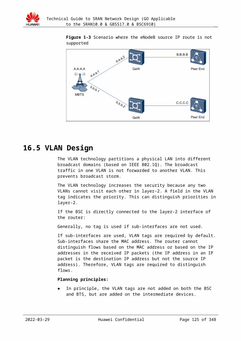
Technical Guide to SRAN Network Design (GO Applicable to the SRAN10.0 & GBSS17.0 & BSC6910)
CONFIDENTIAL
Figure 19-3 Typical A over IP networking mode (pool of active/standby interface boards+dual-active ports)
In actual application, IP addresses of more than two boards form an IP pool.
On the bearer network side: Layer-3 router networking is in use and a pair of independent routers is deployed.On the BSC side: Interface boards adopt the IP pool comprised by logical IP addresses of the active/standby service planes of the board. Device IP addresses are used for communication.Route configuration examples
Device
Source IP
Next Hop
Standby Next Hop
BSC IP150 IP110 IP120
IP170 IP130 IP140
IP160 IP120 IP110
IP180 IP140 IP130
Detection mechanismAfter a transmission resource pool is deployed on the A interface, pooled interface boards in multiple pairs and pooled ports in multiple pairs protect each other.IP pool fault detection and switchover triggering mechanism: Each address in the IP pool on the BSC side automatically starts the ICMP ping detection. If the ICMP ping detection of a pooled IP address fails, services on the faulty links are allocated to other pooled IP addresses.The active port of each board enables two BFD sessions to detect the IP addresses of the two routers. The BSC performs a BFD detection every 100 ms for three times. Configure the delay enabling BFD on CE1 and CE2 to avoid service interruption of CE1 and CE2 due to a reset upon power-off. If BFD is deployed between interface boards and the peer routers, the BSC triggers a switchover of the active/standby gateways in the source IP address routing table. The BSC can detect board faults and if it detects a board fault, the
2023-04-22 Huawei Confidential Page 125 of 258

Technical Guide to SRAN Network Design (GO Applicable to the SRAN10.0 & GBSS17.0 & BSC6910)
CONFIDENTIAL
active/standby boards of the BSC switch over, and the logical IP address is migrated to a normal board from the faulty board. Accordingly, the source IP address route mapping the logical IP address is switched between the active/standby gateways.Analysis of the fault switchover mechanism (only on single-fault scenarios)Fault 1: On the BSC side, the interface board on which IP170 is configured is faulty.On the control plane: Packet receiving by the SCTP links times out and the packets are resent through the standby path. Upper layer signaling indicates that no packets are lost but a time delay of about 1s occurs. The SCTP working links switch to the standby path about 15s after the packets are resent. The destination is reachable all the time. On the user plane: ICMP ping detection on IP170 in the IP pool fails (5 x 5s). IP170 is blocked and subsequent services are provided through IP180.
Optional scheme 2: using a transmission resource poolNetworking: Pool of active/standby boards+manual active/standby LAGsThe BSC is directly connected to the dual routers through the active/standby ports on the active/standby interface boards. All data is sent and received through the active port. VRRP IP addresses are configured between the dual routers, which function as the next hops of the BSC. Heartbeat messages are transmitted over the trunk between CE1 and CE2. Configure multiple VRRP IP addresses between CE1 and CE2 to share loads. As shown in 19.2.7 Figure 19-1, CE1 functions as the high priority router of VRRP1 and CE2 functions as the high priority router of VRRP2.Logical IP addresses of multiple pairs of active/standby interface boards of the BSC form an IP pool. Multiples pairs of active/standby ports of a pair of active/standby boards form a pool. In this networking, because the ports on the interface boards of the BSC side do not support adding ports to the boards of the LAG, new IP addresses must be configured and added to the pool. New IP addresses and new VRRP IP addresses must be also configured on peer devices.The BSC, MSC server, and the MGW are deployed in layer-3 networking mode. The MSC server and the MGW connect to the BSC in loose coupling mode and the BSC can be configured to work in either active/standby mode or load-sharing mode. If an IP pool is deployed on the BSC side, contact peer maintenance engineers to configure the peer device to work in load-sharing mode, which is consistent with the IP pool on the BSC side.The control plane and the user plane use the same physical port. However, the bearer network adopts different VPN isolation for the control plane and the user plane of the A interface. Therefore, different VLANs and ETHIPs must be designed on the BSC side (configure separate ETHIP for the control plane on one pair of interface boards: IP111 and the mapping VLAN, and separate ETHIP for the user plane: IP131 and the mapping VLAN; configure separate ETHIP for the control plane on the other pair of interface boards: IP121 and the mapping VLAN, and separate ETHIP for the user plane: IP141 and the mapping VLAN).
Figure 19-4 Typical A over IP networking mode (pool of active/standby boards+manual active/standby LAGs)
2023-04-22 Huawei Confidential Page 126 of 258
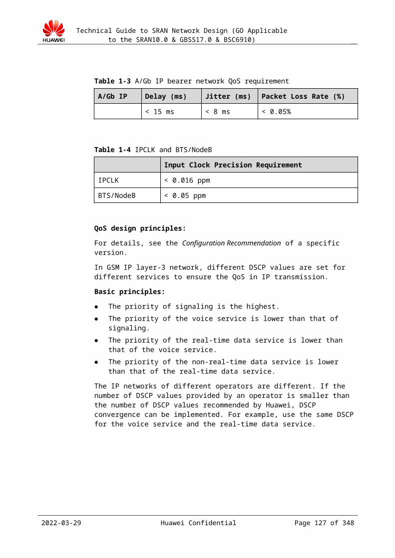
Technical Guide to SRAN Network Design (GO Applicable to the SRAN10.0 & GBSS17.0 & BSC6910)
CONFIDENTIAL
Route configuration examples
Device
Source IP
Next Hop
Standby Next Hop
BSC IP150 IP110
IP170 IP130
IP160 IP120
IP180 IP140
Transmission fault detection schemeAfter a transmission resource pool is deployed on the A interface, pooled interface boards in multiple pairs and pooled ports in multiple pairs protect each other.IP pool fault detection and switchover triggering mechanism: Each address in the IP pool on the BSC side automatically starts the ICMP ping detection. If the ICMP ping detection of a pooled IP address fails, services on the faulty links are allocated to other pooled IP addresses.The active port of a certain pair of active/standby interface boards on the BSC enables two BFD sessions to detect the physical IP addresses (IP110 and IP112) of the two routers, and Whether affect the port swapping is set to YES. The standby port of a certain pair of active/standby interface boards on the BSC enables an ARP detection session to detect the VRRP virtual IP addresses (IP114 and IP124 are configured when the ARP detection is enabled). If faults are detected during both BFD sessions and the ARP detection indicates that the standby port is normal, the active/standby ports switch over.Fault 1: On the BSC side, a pair of active/standby interface boards is faulty.SACK message receiving by data blocks on the active path of the SCTP links times out and the SACK messages are resent through the standby path. Upper layer signaling indicates that no SACK messages are lost but a time delay of about 1s occurs. The SCTP working links switch to the standby path about 15s (1 + 2 + 3 + 3 + 3 + 3) after the SACK messages are resent. Then SACK messages are not resent.ICMP ping detection on an IP address in the IP pool fails (5 * 5s). This IP address is blocked and subsequent services are provided through other IP addresses.
2023-04-22 Huawei Confidential Page 127 of 258
Technical Guide to SRAN Network Design (GO Applicable to the SRAN10.0 & GBSS17.0 & BSC6910)
CONFIDENTIAL
The processing after a pair of active/standby interfaces on the BSC side is faulty is similar to the processing after a pair of active/standby interface boards on the BSC side is faulty.
IP Interface BoardsFor GBSC15.0, only FG2c/FG2d/GOUd/GOUc/EXOUa interface boards support the transmission interface Pool feature.
Compared with the network where the FG2c interface boards are in use, the network where the GOUc/GOUd/EXOUa interface boards are deployed has no limitation on transmission distance and the networking is more flexible. However, the peer end must support GE optical interfaces. If the peer end has GE optical interfaces, use the GOUc/GOUd/EXOUa interface boards.
If the FG2c/FG2d interface boards are in use, only GE/FE electrical interfaces are available and the transmission distance is less than 100 meters (328 ft). Therefore, if the peer end has sufficient GE optical interfaces, use the GOUc/GOUd/EXOUa interface boards.
Restrictions and Constrains of the Transmission Pool NetworkRequirements and specification for the transmission pool networking:
The transmission pool can be used only on layer-3 Ethernet network (an layer-3 route is deployed before the BSC).
Only the FG2c/FG2d/GOUd/GOUc/EXOUa interface boards support the transmission interface Pool feature.
The IP addresses in an IP address pool must be device IP addresses and be configured with the source IP routing. Device IP addresses without source IP routing cannot be added to the IP address pool.
Each IP address can be in only one pool. Interfaces of different systems cannot share the transmission pool.
Impact and constrains:
The load-sharing boards in the pool and the boards that have logical ports configured are mutually exclusive. If boards with logical ports are configured, these boards are preferentially selected. If these boards are faulty or the CPU of these boards is overloaded, other boards are selected.
Output: A over IP networking design
BSC Name
Subrack No.
Slot No.
Board Type
Net Mode
Port Type
Port No.
Configure All
Max Transfer Unit
Auto Negotiation Mode
Port Rate(M)
Duplex Mode
Parameter description:
Board Type: board type. Net Mode: inter-board mode (inter-board active/standby mode, inter-board load-sharing
mode, or standalone mode).
2023-04-22 Huawei Confidential Page 128 of 258
Technical Guide to SRAN Network Design (GO Applicable to the SRAN10.0 & GBSS17.0 & BSC6910)
CONFIDENTIAL
Port Type: port type (GE/10 GE or FE port). Max Transfer Unit, Auto Negotiation Mode, Port Rate(M), and Duplex Mode: must
be consistent with those of the directly connected devices.
19.2.3 SCTP Multi-Homing DesignIn SCTP multi-homing mode, multiple IP addresses on the local and peer end are configured to form multiple IP paths. This can improve the networking reliability and is used in A interface signaling networking (IP over FE/GE).
Implement SCTP multi-homing design based on the networking plan and configuration of the peer MSC server. The scenarios are as follows (scenario 1 is the most recommended one):
19.2.3.1 Scenario 1In A over IP mode, the BSC is configured with two pairs of A interface boards in subrack 0 and subrack 1. Each pair works in active/standby mode. The service and signaling are separated on physical ports. On each pair of boards, one port is allocated for signaling, that is, totally two physical ports are allocated for signaling. Two IP addresses (Local IP1 and Local IP2) are allocated to the two physical ports. The peer MSC server provides two pairs of IP interface boards and two IP addresses (Peer IP1 and Peer IP2) to implement SCTP multi-homing with the BSC. A router is deployed between the BSC and the MSC server. Each pair of interface boards on the BSC must be configured with routes destined for both pairs of interface boards on the peer MSC server to implement four-homing.
On the BSC side, one physical interface board provides two physical ports for signaling. On the peer MSC server side, two pairs of interface boards are available, and each pair provides one physical port for signaling. Alternatively, on the MSC server side, one physical board provides two physical ports for signaling. In both of the preceding cases, the following networking mode shown in Figure 19-1 can be used to implement SCTP multi-homing.
Figure 19-1 SCTP four-homing between the BSC and the MSC server
2023-04-22 Huawei Confidential Page 129 of 258

Technical Guide to SRAN Network Design (GO Applicable to the SRAN10.0 & GBSS17.0 & BSC6910)
CONFIDENTIAL
If bit 1 of P42 on the MSC server is set to 1 (default value), two paths are formed, that is, dual-homing can be implemented. Set bit 1 of P42 to 0 to implement four-homing.
Bit Bit 1
Description It controls whether to enable the new path management mechanism.= 0: The original path management mechanism is used, that is, two source IP addresses, two destination IP addresses, and four paths are available.= 1: The new path management mechanism is used, that is, two source IP addresses, two destination IP addresses, and two paths are available.Default value: 1
Application Scenario
It is used to select a path management mechanism in SCTP multi-homing.
Impact on the System
None.
Related Software Parameter
None.
Public or Not For internal use only
19.2.3.2 Scenario 2An M3UA link is added compared with the networking in scenario 1. Configure local address 1 to Local IP1, peer address 1 to Peer IP2, local address 2 to Local IP2, and peer address 2 to Peer IP1. The other configurations remain unchanged.
2023-04-22 Huawei Confidential Page 130 of 258
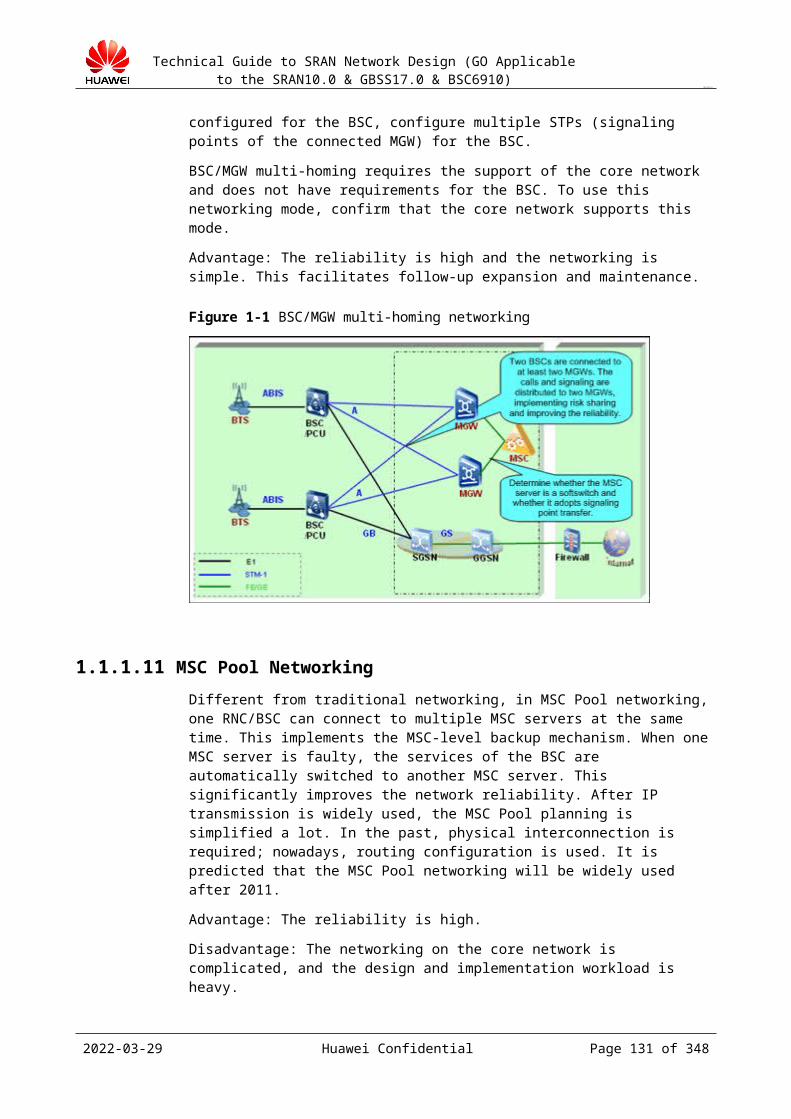
Technical Guide to SRAN Network Design (GO Applicable to the SRAN10.0 & GBSS17.0 & BSC6910)
CONFIDENTIAL
Figure 19-1 Two M3UA links and SCTP four-homing between the BSC and the MSC server
If bit 1 of P42 on the MSC server is set to 1 (default value), two paths are formed, that is, dual-homing can be implemented. Set bit 1 of P42 to 0 to implement four-homing. For detailed information about P42, see the parameter description in scenario 1.
19.2.3.3 Scenario 3In A over IP mode, the BSC is configured with a pair of A interface boards that work in active/standby mode. The signaling and service are separated on physical ports. One physical port is allocated for signaling, and one IP address is allocated to this physical port. The peer MSC server provides two pairs of IP interface boards and two IP addresses to implement SCTP dual-homing on the MSC server side. A router is deployed between the BSC and the MSC server.
2023-04-22 Huawei Confidential Page 131 of 258
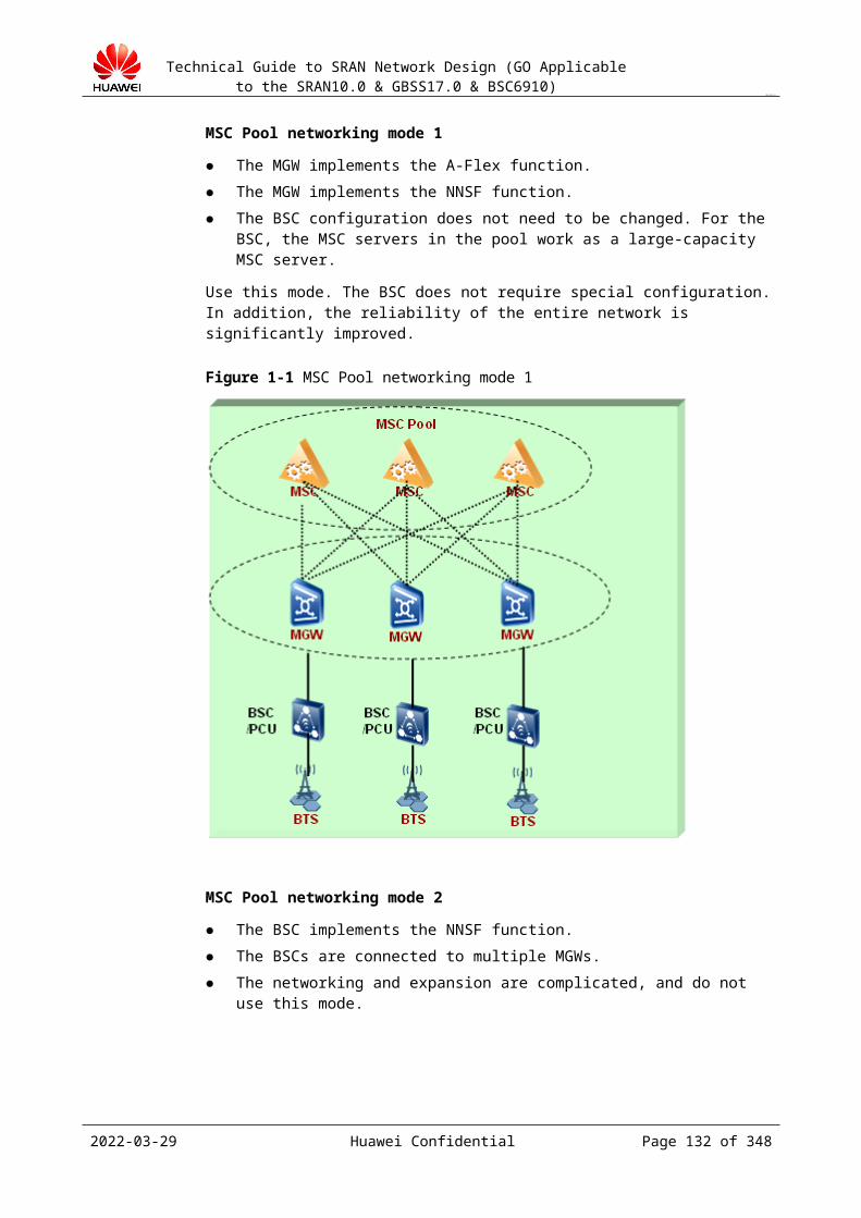
Technical Guide to SRAN Network Design (GO Applicable to the SRAN10.0 & GBSS17.0 & BSC6910)
CONFIDENTIAL
Figure 19-1 SCTP dual-homing on the MSC server side and SCTP single-homing on the BSC side (1)
Bit 1 of P42 on the MSC server is set to 1 by default. Set bit 1 of P42 to 0 to implement SCTP multi-homing on the MSC server side. For detailed information about P42, see the parameter description in scenario 1.
19.2.3.4 Scenario 4In A over IP mode, the BSC is configured with a pair of A interface boards that work in active/standby mode. The signaling and service are separated on physical ports. One physical port is allocated for signaling, and two IP addresses are allocated to this physical port (multi-IP function on the port). The peer MSC server provides two pairs of IP interface boards and two IP addresses to implement SCTP dual-homing on the MSC server side. A router is deployed between the BSC and the MSC server.
2023-04-22 Huawei Confidential Page 132 of 258
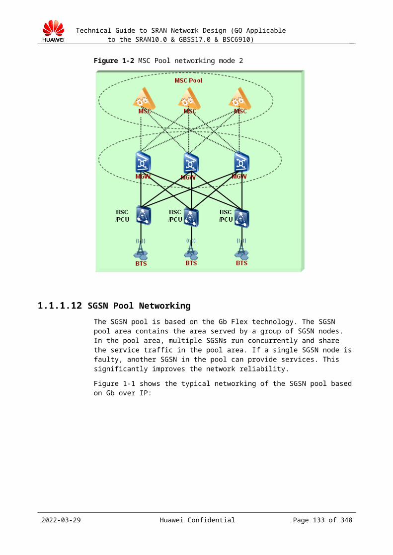
Technical Guide to SRAN Network Design (GO Applicable to the SRAN10.0 & GBSS17.0 & BSC6910)
CONFIDENTIAL
Figure 19-1 SCTP dual-homing on the MSC server side and SCTP single-homing on the BSC side (2)
19.2.3.5 Scenario 5In A over IP mode, the BSC provides two pairs of A interface boards, and each pair works in active/standby mode. The service and signaling are separated on physical ports. Each pair of interface boards provides one port for the signaling, that is, two IP addresses (in different network segments) are configured to the two pairs of interface boards on the BSC. The peer MSC server provides one pair of IP interface boards and one IP address to implement SCTP dual-homing on the BSC side. A router is deployed between the BSC and the MSC server.
2023-04-22 Huawei Confidential Page 133 of 258
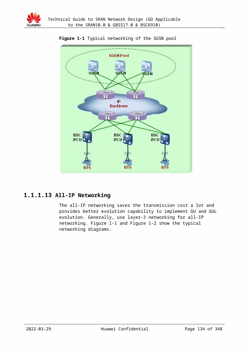
Technical Guide to SRAN Network Design (GO Applicable to the SRAN10.0 & GBSS17.0 & BSC6910)
CONFIDENTIAL
Figure 19-1 SCTP single-homing on the MSC server side and SCTP dual-homing on the BSC side
SummaryBy default, the duration of detection on a single-homing link is 3s during data services and 7s when no service is being processed. The detection duration doubles for a dual-homing link.
For GBSS15.0: The RTO min value can be set to 50 ms. However, if the system performs detection frequently, the SCTP links may repeatedly switch over if transmission condition is poor.
First local IP address and Second local IP address of an SCTP link must be service IP addresses (device IP addresses are recommended). Two pairs of the A interface boards provide a port respectively to implement SCTP multi-homing.
Output: SCTP link
Linkset name
Local Port No.
Local Address 1
Local Address 2
Peer Address 1
Peer Address 2
Peer Port No.
Parameter description:
Linkset name: name of the link set to which the M3UA link belongs. It is planned on the BSC internally.
Local Port No.: local port number. It must be negotiated with the peer end. Local Address 1: first local IP address. It must be negotiated with the peer end.
2023-04-22 Huawei Confidential Page 134 of 258

Technical Guide to SRAN Network Design (GO Applicable to the SRAN10.0 & GBSS17.0 & BSC6910)
CONFIDENTIAL
Local Address 2: second local IP address. It is required only when SCTP multi-homing is enabled. It must be negotiated with the peer end.
Peer Address 1: first peer IP address. It must be negotiated with the local end. Peer Address 2: second peer IP address. It is required only when SCTP multi-homing is
enabled. It must be negotiated with the local end. Peer Port No.: peer port number. It is planned on the BSC internally.
19.2.4 Signaling Bandwidth CalculationCalculation method
Use the GSM NEP tool to calculate the bandwidth.
For details, see section Error: Reference source not found.
Output of the design
BSC Name
Traffic Signaling link type
Bandwidth per link
Signalingquantity
Subrack Number 0
Subrack Number 1
Subrack Number 2
7000 64 kbit/s/2 Mbit/s
64 kbit/s/256/512/1024/2 Mbit/s
6 2 2 2
19.2.5 Signaling Configuration PrinciplesIf the A interface adopts IP transmission, M3UA signaling links are used, and broadband signaling and narrowband signaling are not distinguished. Each SCTP/M3UA link supports a maximum of 4,000 Erlang (it is an experience-based estimated value and not presented to the customer) traffic. Each SCTP link maps an M3UA link. In signaling design, configure one SCTP link to bear 4,000 Erlang traffic.
In terms of reliability, configure at least two links regardless of the traffic load. If the A interface adopts IP transmission, M3UA signaling links are used, and broadband signaling and narrowband signaling are not distinguished.
Take the signaling balance and reliability of the BSC into account when configuring signaling links. The principles are as follows:
In A over IP mode, bandwidth for M3UA links needs not to be configured. Each M3UA link supports about 4,000 Erlang traffic. To improve reliability, configure an M3UA link set for each BSC, and the M3UA link set contains at least four M3UA links that are distributed to boards in different subracks.
In A over IP mode, use the SCTP multi-homing for signaling links to improve reliability. For details, see section 19.2.3 "SCTP Multi-Homing Design."
2023-04-22 Huawei Confidential Page 135 of 258
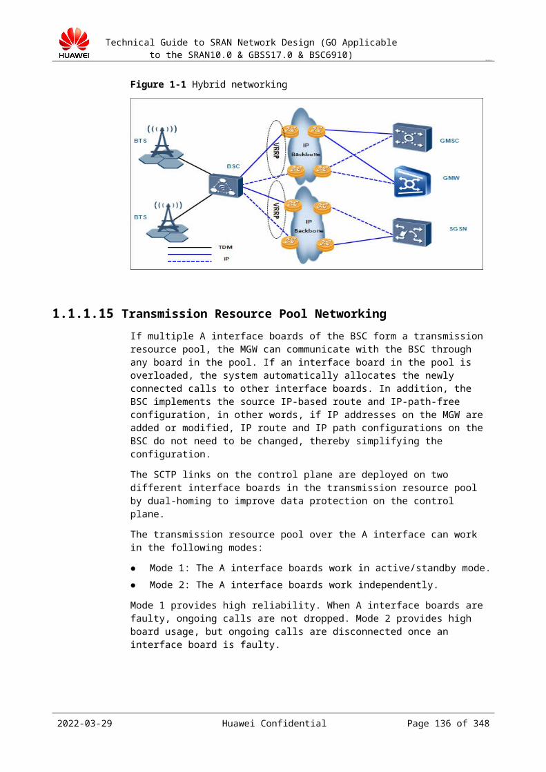
Technical Guide to SRAN Network Design (GO Applicable to the SRAN10.0 & GBSS17.0 & BSC6910)
CONFIDENTIAL
19.2.6 Traffic Bandwidth CalculationThis chapter provides engineers with a guide to the calculation of the number of CICs and transmission bandwidth of the A interface. For calculation methods, see section Error: Reference source not found.
Use the GSM NEP tool to calculate the bandwidth.
Methods and principles of bandwidth calculation
Method 1:
Cell channel configuration -> Checking the ErlangB table -> Cell traffic -> Sum of the traffic of all the cells in the BSC -> Total BSC traffic -> Checking the ErlangB table -> Number of CICs of the A interface
Method 2:
Traffic per subscriber x Number of subscribers -> Total BSC traffic -> Dividing by 0.7 (traffic per CIC) -> Number of CICs of the A interface
Generally, the network design tool uses the first calculation method (this method is adopted in pre-sales marketing). The redundancy of A interface bandwidth calculated using this method is sufficient, and this method does not cause transmission bottleneck of the BSC. The result obtained using the second calculation method is precise, and the second method is applicable to the scenario where transmission resources are insufficient to meet the minimum transmission requirements.
Output of the design
Table 19-1 Calculation result of A interface bandwidth in IP transmission mode
BSC Name
Traffic (Erlang)
System Congestion Ratio
Number of CICs of the A Interface
IP Transmission Bandwidth
7000 10-6
19.2.7 IP Address Planning (A over IP)The IP addresses of the interface boards of the BSC include device IP addresses (logical IP addresses) and physical port IP addresses. Physical ports support the configuration of multiple IP addresses. In the GBSS9.0 and later versions, the IP interface board supports multiple device IP addresses. The following uses the PIU as the common name of the A interface board, Gb interface board, and Abis interface board. The device IP communication mode is in use. The device IP address uses the 32-bit mask to save IP resources.
Design principles:
The planned IP addresses must facilitate follow-up maintenance. The planned IP addresses must meet the expansion requirements in a certain period in
future. Plan VLAN tagging based on the next hop or service type to facilitate follow-up
maintenance and expansion.
2023-04-22 Huawei Confidential Page 136 of 258
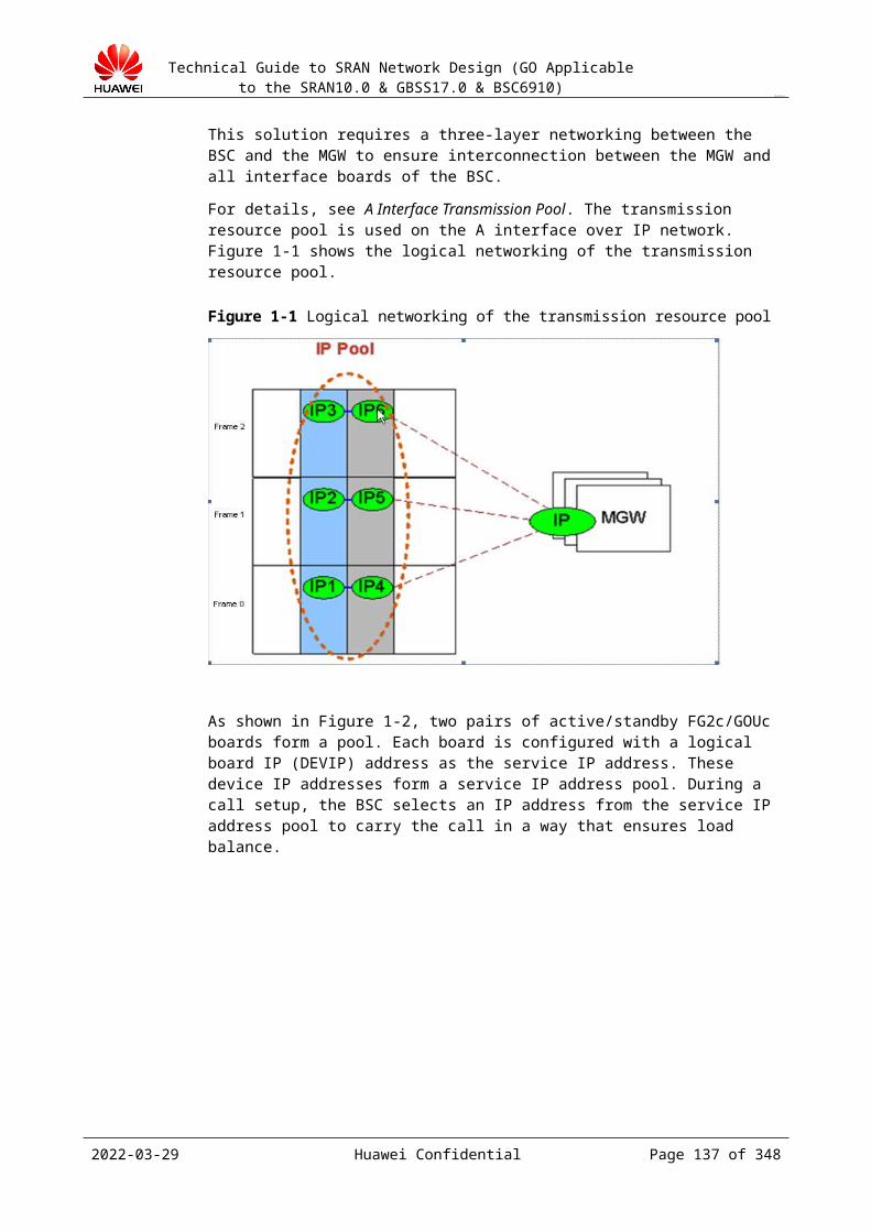
Technical Guide to SRAN Network Design (GO Applicable to the SRAN10.0 & GBSS17.0 & BSC6910)
CONFIDENTIAL
Design guide:
Step 1 Allocate device IP addresses based on the A interface networking design and number of FE/GE/10 GE ports calculated in the bandwidth design.
Step 2 Allocate port IP addresses. In the active/standby boards+manual active/standby LAGs, configure an IP address for the active port. Configure an IP address for the standby port only when the ARP detection is performed on the standby port. The IP addresses of the active/standby ports must be in the same network segment.
Step 3 If layer-3 networking is used and the device IP address is used for communication, configure a route from the intermediate router to the device IP address of the BSC. If layer-3 networking is used and the port IP address is used for communication, a route from the intermediate router to the port IP address of the BSC is not required.
Step 4 If the end-to-end solution requires that VLAN tags be added on the BSC side based on different destination IP addresses, add VLAN tags based on the next hop or service type on the BSC side.
Step 5 If the control plane and the user plane are separated using multiple IP addresses on the physical port, configure the BSC to add different VLAN tags based on different next hops.
----End
Principles of IP address planning
The device IP address of a board is the logical IP address that the board uses for communication. The device IP address is valid for all the port IP addresses of the board. Use the pool of independent board networking mode.
For the FG2c board, if the FE interface mode is adopted, one board can be configured with 12 port IP addresses that are in different network segments. If the GE interface mode is adopted, one board can be configured with four port IP addresses. In addition, the port IP addresses and the device IP address must be in different network segments. If the PIU adopts the active/standby configuration, only the port on the active board is allocated with an IP address.
The gateway IP address must be in the same network segment as the port IP address of the PIU.
One physical port can be configured with a maximum of six IP addresses. The multiple IP function is supported. The IP addresses of the same physical port must be in different network segments.
The BSC can add VLAN tags based on the next hop or service type. The VLAN ID ranges from 2 to 4094.
If the interface communication mode is device IP communication, the port IP address works as the gateway IP address used to communicate with other external devices. If the interface communication mode is port IP communication, the port IP address works as the IP address used to communicate with other external devices. In addition, each PIU can be configured with a maximum of eight service logical IP addresses. A service logical IP address works as the source or destination IP address used to communicate with other external devices.
For the PIU, the 12 FE ports and four GE ports adopt the router mode, that is, the IP addresses of the FE ports must be in different network segments. In addition, to simplify the implementation, the device IP address (logical IP address) of each PIU and the port IP address of the PIU must be in different network segments.
The PIU interface board of the BSC adopts the routing mode. The IP addresses of the FE ports on the same interface board must be in different network segments. In addition, the IP addresses of the FE ports on different interface boards must be in different network segments.
2023-04-22 Huawei Confidential Page 137 of 258
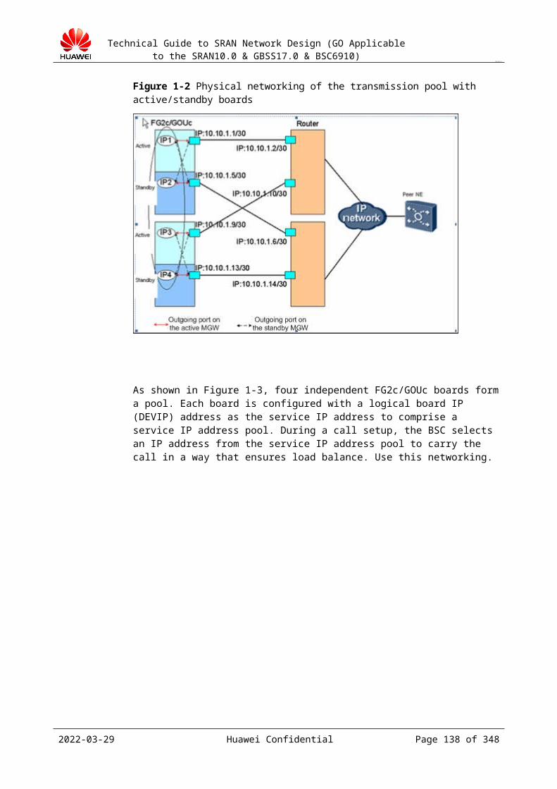
Technical Guide to SRAN Network Design (GO Applicable to the SRAN10.0 & GBSS17.0 & BSC6910)
CONFIDENTIAL
Example:
Figure 19-1 shows the IP network topology of the BSC.
Figure 19-1 IP network topology of the BSC
In Figure 19-1:
IP_1 to IP_4 (in yellow) are the IP addresses used only for the internal communication in the BSC. This type of address is generated automatically and does not need to be configured. Users do not sense and do not need to pay attention to this type of IP address.
IP1 to IP8 are the port IP addresses that need to be planned on the BSC side. The port IP addresses must be in different network segments.
IP_L1 and IP_L2 are the device IP addresses (logical IP addresses) to be planned for the PIU on the BSC side. Each PIU can be configured with a maximum of eight logical IP addresses.
19.2.8 Routing Planning (A over IP)Design guide:
Step 1 Plan BSC routing based on the A interface networking design, IP address of the MSC server, IP address of the MGW, and current IP address planning of the A over IP interface board. The BSC needs to be configured with routes to the MGW and MSC server.
Step 2 If the A interface adopts the device IP address for communication, routes to the device IP address of the BSC need to be configured on the MGW and MSC server.
Step 3 If the A interface adopts the device IP address for communication and layer-3 networking is used, routes to the device IP address of the BSC need to be configured on the intermediate router.
----End
Principles of routing planning:
2023-04-22 Huawei Confidential Page 138 of 258

Technical Guide to SRAN Network Design (GO Applicable to the SRAN10.0 & GBSS17.0 & BSC6910)
CONFIDENTIAL
If the router adopts the VRRP+VLANIF networking mode, the gateway IP address in the routing information configured for the A interface board of the BSC is the VRRP IP address or the port IP address of the device directly connected to the port.
Routes to the MGW and MSC server need to be configured on the BSC. In layer-2 networking mode, routes to the MGW and MSC server are not required.
In BSC active/standby mode, configure routes only on the active board to the MGW and MSC server. In load-sharing mode, however, configure routes on both load-sharing boards to the MGW and MSC server.
If the A interface of the BSC adopts the device IP address for communication, configure routes on the MGW and MSC server to the device IP address of the BSC regardless of whether the layer-3 or layer-2 networking mode is used. In layer-3 networking mode, configure a route on the intermediate router to the device IP address of the BSC.
Output:
Index No.
Subrack No.
Slot No.
Outgoing Port No.
Destination IP Address
Subnet Mask
Gateway
To MSC/MGW
Parameter description:
Outgoing Port No.: port number of the outgoing port from the A interface board of the BSC to the peer MGW or MSC server.
Destination IP Address: network IP address of the device IP address of the peer MGW/MSC server (destination of the data from the A interface board of the BSC). If the peer MGW or MSC server does not have a device IP address (logical IP address), this parameter indicates the network IP address of the port IP address. The network IP address is obtained by performing the AND operation on the device IP address (or port IP address if no device IP address is available) of the MGW or MSC server and the subnet mask.
Subnet Mask: subnet mask of the IP address of the peer MGW or MSC server. Gateway: port IP address of the device directly connected to the outgoing port (indicated
by Outgoing Port No.) of the A interface board of the BSC. This IP address must be in the same network segment as the IP address of the outgoing port of the A interface board.
To MSC/MGW: The routes to the MSC server and MGW need to be configured separately because the control plane and service plane are separated for the A interface.
19.2.9 QoS Design (A over IP)Design principles:
Port link detection− The BFD detection and ARP link detection cannot be enabled at the same time on the
interface board. The BFD detection supports SBFD detection (single-hop BFD detection, recommended) and MBFD detection (multiple-hop BFD detection), and the BFD detection requires the next-hop device to support the BFD detection. (The function that the ARP link detection implements is similar to the single-hop BFD detection. Generally, it takes several seconds to detect a fault in the ARP link detection, but takes only tens of milliseconds to detect a fault in the BFD detection. However, the ARP link detection can be implemented as long as one end supports the
2023-04-22 Huawei Confidential Page 139 of 258

Technical Guide to SRAN Network Design (GO Applicable to the SRAN10.0 & GBSS17.0 & BSC6910)
CONFIDENTIAL
ARP detection, but the BFD detection can be implemented only if both ends support the BFD detection.)
− One port can be configured with only one detection mode. If a port is not configured with the BFD detection or ARP link detection, the physical-layer detection is adopted by default.
− The following detection modes are supported: BFD detection on the active port and ARP detection on the standby port (the standby port does not support BFD detection), ARP link detection on the active and standby ports, BFD detection on the active port and physical-layer detection on the standby port, ARP detection on the active port and physical-layer detection on the standby port, and physical-layer detection on the active and standby ports. Do not use the MBFD detection. If the customer requires the MBFD detection, the Huawei headquarters need to work out a solution.
− The commonly used detections are the ARP detection and physical-layer detection. The physical-layer detection does not require data configuration, and the ports support this detection by default. The configurations recommended for the ARP detection are as follows: number of retries: 3, interval: 300 ms.
Figure 19-1 shows the promoted detection mode.
Figure 19-1 Promoted detection mode in active/standby mode
Logical port− The logical port bandwidth is different from other types of bandwidth. For the logical
port bandwidth, 1 represents 64 bit/s.− Reserved bandwidth of the logical port = Reserved bandwidth threshold of the logical
port x Logical port bandwidth− Congestion bandwidth of the logical port = Congestion bandwidth threshold of the
logical port x Logical port bandwidth− Congestion clearance bandwidth of the logical port = Congestion clearance threshold
of the logical port x Logical port bandwidth QoS parameters
See the Configuration Recommendation of the specific version. VLAN
2023-04-22 Huawei Confidential Page 140 of 258
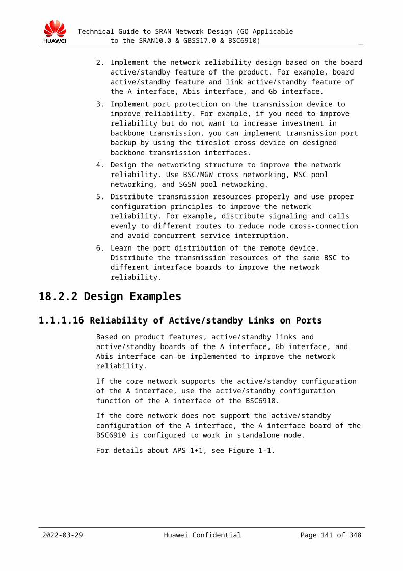
Technical Guide to SRAN Network Design (GO Applicable to the SRAN10.0 & GBSS17.0 & BSC6910)
CONFIDENTIAL
In A over IP mode, only several pairs of boards are used, and the volume of broadcast packets is small. Therefore, VLAN is not necessary. Add VLAN tags based on the next hop or add VLAN tags on the intermediate transmission devices.
Output: A over IP QoS design
ARP link detection
Subrack No.
Slot No.
Port No.
IP Address Index
Peer IP Address
Arp Retry Attempts
Arp Timeout
VLAN Flag
VLAN ID
Peer IP Address of the Standby Board
Parameter description:
Port No.: port number of the A interface board that requires the physical link detection. IP Address Index indicates the IP address index. The system supports the configuration
of multiple IP addresses for a port. Peer IP Address: port IP address of the device that is directly connected to the physical
port. Arp Retry Attempts: number of ARP detection times in a period. The default value is 3. ARP Timeout: ARP response timeout interval (after an ARP request is sent) in the ARP
detection. The default timeout interval is 3 seconds. Use the default value 3. The software has a bug, and do not change the value.
VLAN Flag: whether VLAN tags are added to ARP packets when the BSC implements ARP detection. If the VLAN function is enabled on the device port that possesses the gateway IP address of the route configured on the port, this parameter must be enabled, and the VLAN ID must be the same as the VLAN ID configured for the device port that possesses the gateway address; otherwise, the route is unreachable.
VLAN ID: VLAN ID in the ARP detection packets when VLAN Flag is set to Enable. Peer IP Address of the Standby Board: physical IP address of the peer port directly
connected to the physical port of the standby board.
BFD detection
Subrack No.
Slot No.
Port No.
IP Address Index
Peer IP Address
MinTxInterval(ms)
MinRxInterval(ms)
Detect Mult
Peer IP Address of the Standby Board
Parameter description:
Peer IP Address: peer IP address in the BFD session. The BFD detection supports only the next hop detection. Therefore, the peer IP address in the BFD session is the port IP address of the device that is directly connected to the port.
MinTxInterval(ms): minimum interval between the BFD control packets that the local system sends.
2023-04-22 Huawei Confidential Page 141 of 258
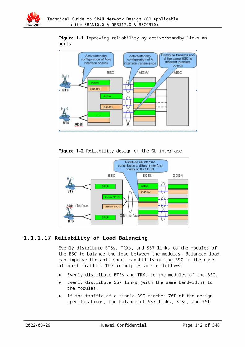
Technical Guide to SRAN Network Design (GO Applicable to the SRAN10.0 & GBSS17.0 & BSC6910)
CONFIDENTIAL
MinRxInterval(ms): minimum interval between the BFD control packets that the local system receives.
Detect Mult: number of detection times, that is, the link is considered disconnected after the detection fails for the specified number of times.
For details about the other parameters, see the parameter description in "ARP link detection."
Logical port
Subrack No.
Slot No.
Physical Port No.
Logic Port No.
Bandwidth of the Logical Port(32Kpbs)
Reserved Bandwidth Threshold(%)
Congestion Bandwidth Threshold(%)
Congestion Clear Bandwidth Threshold(%)
Parameter description:
Physical Port No.: physical port number of the interface board to which the logical port belongs.
Bandwidth of the Logical Port(32Kpbs): fixed bandwidth of the logical port. It ranges from 32 kbit/s to 64 kbit/s. The sum of the bandwidths of all the logical ports bound to the same physical port cannot exceed the bandwidth of the physical port.
For details about the other parameters, see the parameter description in "IP Path."
19.2.10 Interface InterworkingIn interface interworking, the following must be taken into consideration:
Protocol type Protocol phase identifier (Phase2, or Phase2+, GSM_PHASE_2+ is recommended) OSP DSP Whether to use signaling point transfer, and whether to adopt a single signaling point or
multiple signaling points
The preceding information needs to be negotiated between the core network personnel and the customer.
Table 19-1 A interface interworking parameters
Parameter Name
Recommended Value
Description
OSP Name BSC It is consistent with the BSC name in the BSC attribute.
OSP Code None Set it to the hexadecimal signaling point code (SPC) that is actually planned by the customer.
OSP Code Bit None Set it to the actual encoding rule of the country. In China, it is 14bit.
2023-04-22 Huawei Confidential Page 142 of 258

Technical Guide to SRAN Network Design (GO Applicable to the SRAN10.0 & GBSS17.0 & BSC6910)
CONFIDENTIAL
Parameter Name
Recommended Value
Description
Network ID None Set it to the actual network indicator of the country. In China, it is NATB.
DSP Name MSC Use MSC as the name or use the actual NE name.
DSP Code None Set it to the hexadecimal SPC of the interworking MSC server.
Is using STP? None If the interworking is implemented using the MGW, enable this switch; if the BSC interworks with the MSC server directly, disable this switch.
STP MGW Use MGW as the name or use the actual NE name.
STP Code None Set it to the hexadecimal SPC of the signaling transfer MGW.
MCC Planned on the customer network
It uniquely identifies the country to which the mobile subscribers belong. The value range is 000 to 999. For example, the MCC of China is 460.
MNC Planned on the customer network
It identifies the public land mobile network (PLMN) to which the mobile subscribers belong.The value range is 000 to 999.
LAC Planned on the customer network
It indicates the local area code. The value range is 0 to 65535.
CI Planned on the customer network
It indicates the cell identification. The value range is 0 to 7999.
A interface tag Negotiated with the peer endGenerally, it is set to GSM_PHASE_2+.
It indicates the GSM protocol phase identifier supported by the A interface. Set it based on the A interface phase identifier provided by the MSC server.Value: GSM_PHASE_1 GSM_PHASE_2 GSM_PHASE_2+ If the system supports the GPRS and AMR services, the A interface phase identifier must be set to GSM_PHASE_2+.
Speech Version Negotiated with the peer end
Full-rate version 1, full-rate version 3, half-rate version 1, and half-rate version 3 are supported. Set it based on the actual voice version.
Encryption type Negotiated with the peer end
The bits, from the most significant bit to the least significant bit, respectively indicate whether the A5/0, A5/1, A5/2,..., and A5/7 algorithms are supported. The value 1 indicates that the BSS supports the encryption algorithm. The value 0 indicates that the BSS does not support the encryption algorithm. Confirm the supported
2023-04-22 Huawei Confidential Page 143 of 258
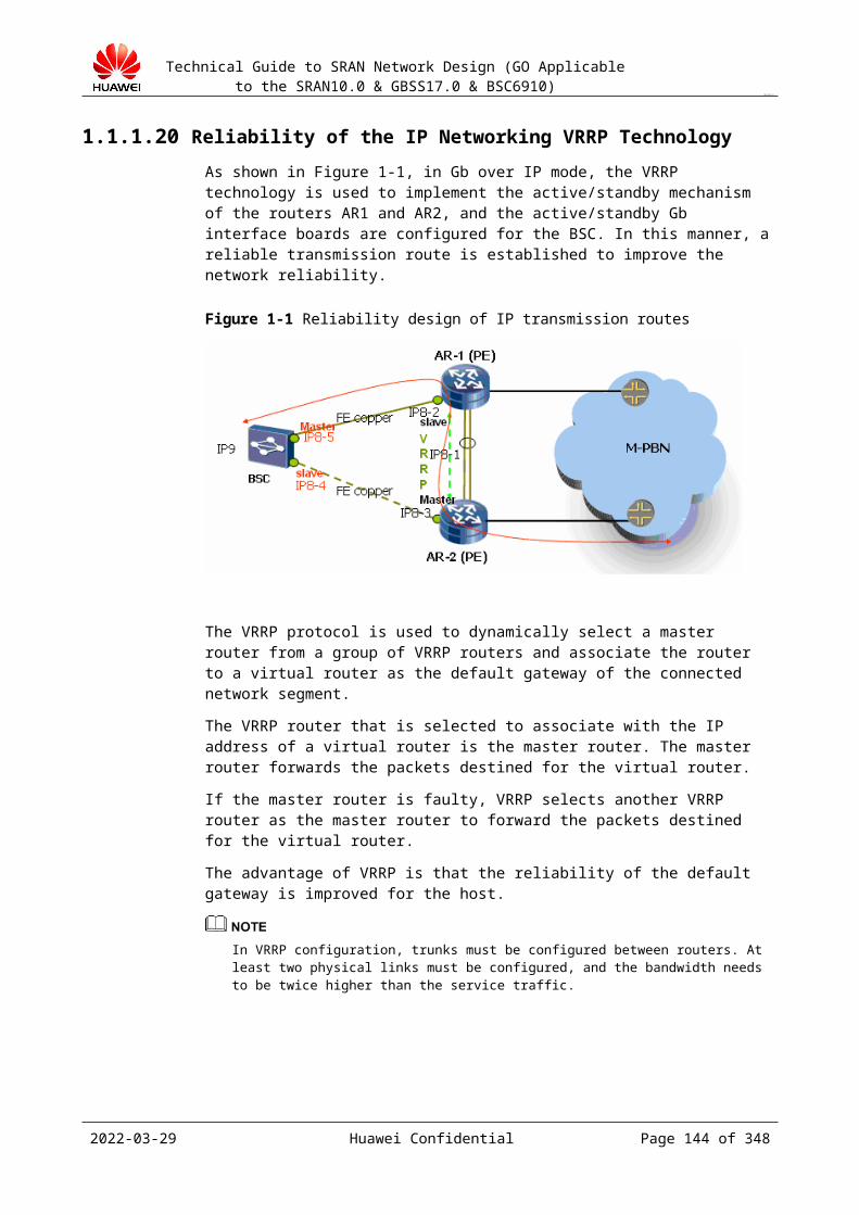
Technical Guide to SRAN Network Design (GO Applicable to the SRAN10.0 & GBSS17.0 & BSC6910)
CONFIDENTIAL
Parameter Name
Recommended Value
Description
encryption algorithms. It cannot be set to all 0s. The most significant bit must be set to 1, that is, the A5/0 algorithm must be supported.
A over IP interworking instance in the P project on the live network:
The following document provides the interworking parameter planning of the BSC in A over IP transmission mode on the live network.
19.3 A Interface Design (TDM)
19.3.1 Interface Description
The A interface is between the BSS and the MSC. In versions earlier than BSC6910 V100R015C01, the BSC6910 only supports A over IP transmission. In BSC6910 V100R015C01 and later, the BSC6910 also supports A over TDM transmission (only the optical interface is supported, and the interface board is POUc).
The protocols over the A interface are as follows:
1. TDM-based Interface
Physically, the A interface is a trunk circuit and trunk interface between the BSS and the MSC. The following figure illustrates the reference protocol model on the control plane over the A interface.
2023-04-22 Huawei Confidential Page 144 of 258
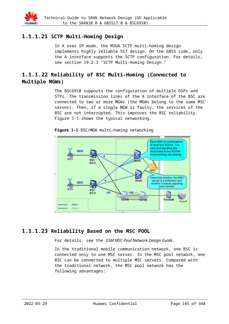
Technical Guide to SRAN Network Design (GO Applicable to the SRAN10.0 & GBSS17.0 & BSC6910)
CONFIDENTIAL
Figure 19-1 Reference protocol model on the control plane of the A interface
BSSAP: Base Station Subsystem Application PartBSSMAP: Base Station Subsystem Management Application PartDTAP: Direct Transfer Application PartMTP: Message Transfer PartSCCP: Signaling Connection Control Part
Protocol and specifications that the A interface complies with are as follows:
Physical layer: complies with ITU-T G.703, G.704, G.705, and G.732. MTP: complies with ITU-T Q.701-Q.704, Q.706, and Q.707. SCCP: complies with ITU-T Q.711-Q.714 and Q.716. BSSAP: complies with 3GPP TS 48.008, 3GPP TS 24.008, and 3GPP TS 44.018.
BSC6910 V100R015C01 has the following restrictions:
Only the POUc interface board is supported in A over TDM transmission mode. The Ater interface is not supported. That is, BM/TC separated mode, remote TC, TC
pool, and Ater over IP are not supported. TDM/IP dual-stack is not supported. The control plane can use IP transmission and the user plane can use TDM transmission.
19.3.2 Networking Design
The A over TDM transmission is a traditional networking mode over the A interface on a GSM network. The following figure shows a typical topology.
2023-04-22 Huawei Confidential Page 145 of 258
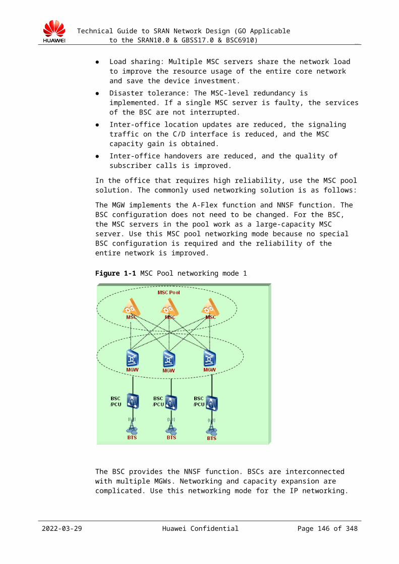
Technical Guide to SRAN Network Design (GO Applicable to the SRAN10.0 & GBSS17.0 & BSC6910)
CONFIDENTIAL
Figure 19-1 BSCs connected to an MGW
Generally, a BSC is connected to an MGW and both of them are homed to the same MSC.
To improve network reliability, distribute A interface traffic and signaling on the BSC to different MGWs if two or more MGWs are available under an MSC. This enables the BSC to properly provide services even if any of the MGWs is faulty, as shown in the following figure.
Figure 19-2 BSCs connected to multiple MGWs
19.3.3 Transmission Bandwidth Design
For details about how to calculate the transmission bandwidth, see section 10.2.3.
2023-04-22 Huawei Confidential Page 146 of 258

Technical Guide to SRAN Network Design (GO Applicable to the SRAN10.0 & GBSS17.0 & BSC6910)
CONFIDENTIAL
19.3.4 Signaling Configuration Principles
In an SS7 network, two types of signaling links are used: 64 kbit/s links and 2 Mbit/s high-speed signaling links. The 2-Mbit/s signaling links consist of the standard signaling links at the rate of 2048 kbit/s and signaling links at the rate of N x 64 kbit/s (N ranges from 2 to 31).
Specifications of signaling points:
A BSC can be configured with a maximum of four local signaling points.
Specifications of SS7 signaling links:
Narrowband signaling link: The bandwidth of each signaling link is 64 kbit/s. A single signaling point can be configured with a maximum of 16 narrowband signaling links, and a BSC can be configured with a maximum of 64 (16 x 4) narrowband signaling links.
2 Mbit/s signaling link: The bandwidth of each signaling link is 2 Mbit/s. The maximum bandwidth for a single signaling point is 16 Mbit/s. A BSC can be configured with 32 2 Mbit/s signaling links. That is, the maximum bandwidth for the BSC is 64 Mbit/s.
The bandwidth calculation method and processing for a narrowband signaling link are the same as those for a high-speed signaling link. The only difference between a narrowband signaling link (64 kbit/s) and a high-speed signaling link (2 Mbit/s) lies in the bandwidth. The bandwidth of a narrowband signaling link is 64 kbit/s while that of a high-speed signaling link is N x 64 kbit/s (N ranges from 2 to 31).
As stipulated in GSM protocols Q.703 and Q.704, a maximum of 16 signaling links can be configured between two signaling points. If 64 kbit/s signaling links are used, the maximum bandwidth for signaling links between two signaling points can be 1 Mbit/s (16 x 64 kbit/s).
In A over TDM transmission mode, the BSC6900 supports the following two methods for increasing the capacity of signaling links:
Using local multiple signaling points: The BSC6900 supports a maximum of four local signaling points. The maximum number of signaling links that can be configured over the A interface increases to 64.
Using 2 Mbit/s signaling links: The maximum bandwidth for each 2 Mbit/s signaling link can reach 1984 kbit/s.
The MTP3 signaling link set and signaling route mask are designed as follows:
Check whether the signaling link mask for the MTP3 signaling link set is appropriately configured.Assume that the number of digits 1 in the signaling link mask (in binary) for the signaling link set is n. If 2n is greater than or equal to the number of signaling links contained in the signaling link set, the configuration is appropriate. Otherwise, the configuration is inappropriate.For example, assume that the signaling link mask is B0001 (the digits after B are binary numbers). If the maximum number of signaling links contained in the signaling link set is 2, the configuration is appropriate. If the maximum number of signaling links contained in the signaling link set is greater than 2, the configuration is inappropriate, and the signaling link mask must be reconfigured.
Check whether the signaling route mask for the destination signaling point is appropriately configured.
2023-04-22 Huawei Confidential Page 147 of 258
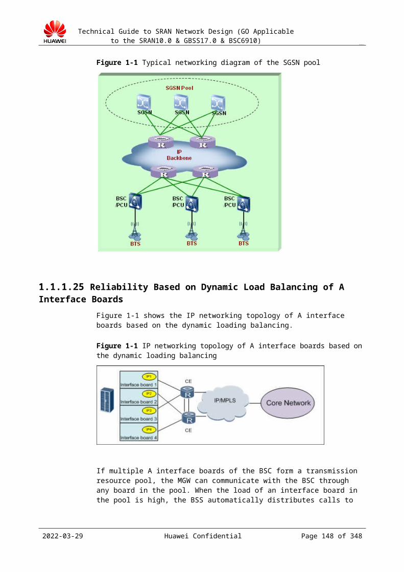
Technical Guide to SRAN Network Design (GO Applicable to the SRAN10.0 & GBSS17.0 & BSC6910)
CONFIDENTIAL
Assume that the number of digits 1 in the signaling route mask (in binary) for the destination signaling point is n. If 2n is greater than or equal to the number of routes contained in the destination signaling point, the configuration is appropriate. Otherwise, the configuration is inappropriate.For example, assume that the signaling route mask is B0001 (the digits after B are binary numbers). If the maximum number of routes contained in the destination signaling point is 2, the configuration is appropriate. If the maximum number of routes contained in the destination signaling point is greater than 2, the configuration is inappropriate, and the signaling route mask must be reconfigured.In versions earlier than GBSS14.0, the result of the "and" operation performed between the signaling route mask and signaling link mask must be 0. Otherwise, signaling load may be unbalanced. In GBSS14.0 and later, this restriction no longer applies, and the default signaling route mask is B1111.
Local signaling points of the BSC6900 are not bound to the BM subrack. Therefore, a single subrack can be configured with four local signaling points. If the CN does not support wideband signaling, it is recommended that local multiple signaling points are configured for the BSC (in version earlier than GBSS9.0, source signaling points are bound to the BM subrack and TCS; in GBSS9.0 and later, source signaling points are no longer bound to the subracks. Therefore, a single subrack can be configured with multiple source signaling points even if only an A interface board is available). When local multiple signaling points are configured, the signaling point binding relationship between cells and CICs must be configured. It is recommended that cells be homed to different signaling points based on their areas. (The inter-cell handover procedure between different signaling points is similar with the inter-BSC handover procedure. Therefore, cell homing based on areas can decrease the number of such handovers.)
In A over IP transmission mode, the signaling links are M3UA links which do not distinguish wideband and narrowband signaling links. Each SCTP or M3UA link supports maximum traffic volume of 4000 Erlang (this value is based on experience and not provided for customers. It is equivalent to the number of speech channels supported by 16 64 kbit/s SS7 signaling links. Each 64 kbit/s signaling link supports 256 CIC speech channels). During the signaling design, you are advised to set an SCTP link per 4000 Erlang.
To ensure reliability, a minimum of two SCTP links must be configured regardless of traffic volume.
In A over IP transmission mode, the signaling links are M3UA links which do not distinguish wideband and narrowband signaling links.
In TDM transmission mode, the configuration of signaling links must comply with the following rules to ensure the signaling load balancing and reliability:
When high-speed signaling links are used, the restrictions on the number of signaling links and bandwidth supported by the PARC platform must be considered. A maximum of eight high-speed signaling links can be configured in each GMPS/GEPS, and the total bandwidth for each GMPS/GEPS cannot exceed 4 Mbit/s. In GBSS8.1 and earlier versions, this restriction applies. In GBSS9.0 and later, this restriction does not apply.
A maximum of 32 2-Mbit/s signaling links can be configured. High-speed signaling links and 64 kbit/s signaling links cannot be simultaneously
configured between the BSC and the same destination signaling point. The BSC6900 supports simultaneous configuration of high-speed signaling links and
local multiple signaling points.
2023-04-22 Huawei Confidential Page 148 of 258
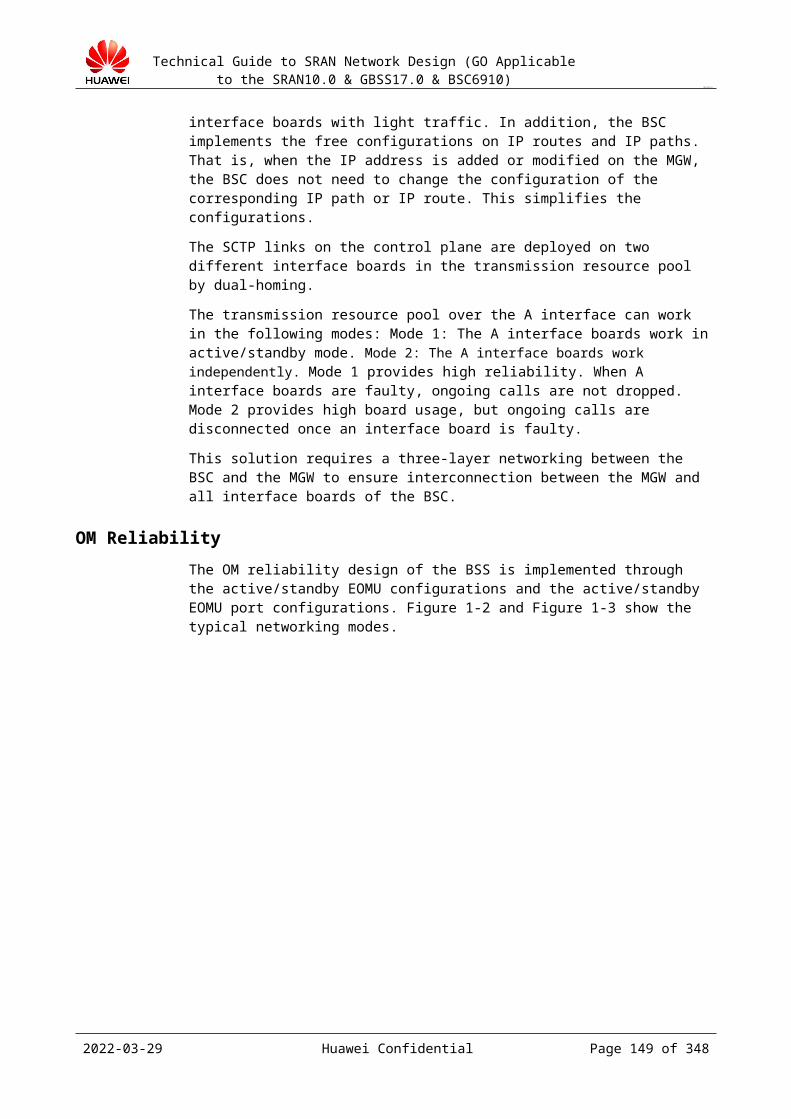
Technical Guide to SRAN Network Design (GO Applicable to the SRAN10.0 & GBSS17.0 & BSC6910)
CONFIDENTIAL
Different bandwidths can be configured for each high-speed signaling link. Since the SS7 signaling links use load sharing, the same bandwidth can be set for multiple SS7 high-speed signaling links.
Any combination of timeslots (except timeslot 0) on an E1 link can form a high-speed signaling link.
Under the same signaling point, at least two high-speed signaling links must be configured. The two signaling links are distributed to different STM-1 ports of an A interface board or to different A interface boards to improve the reliability.
The BSC supports MSC Pool. A BSC can be connected to multiple MSCs. In TDM transmission mode, the SS7 configuration is determined according to the proportion of the number of A CICs between the BSC and MSC to the total number of A CICs.
19.4 Gb Interface DesignIn new offices of the BSC6910, the embedded PCU is used; therefore, the external PCU solution is not taken into consideration in the Gb interface design.
19.4.1 Interface DescriptionThe Gb interface connects the BSC (including the PS service) and the SGSN after the PCU is embedded, and it is the standard interface defined in the protocol.
The Gb interface of the GBSS15.0 BSC6910 supports only IP networking mode.
Figure 19-1 shows the protocol model of the Gb interface.
Figure 19-1 Gb over IP protocol stack
The Gb interface implements the communication between the SGSN and the BSS system and between the SGSN and MSs, transmits packet data, manages the mobility, and manages sessions. The Gb interface is mandatory in GPRS networking.
Physical-layer protocol L1The physical-layer configurations and protocols defined in GSM 08.14 can be used. Physical resources are configured in the O&M process.
Network service layer (NS)
2023-04-22 Huawei Confidential Page 149 of 258
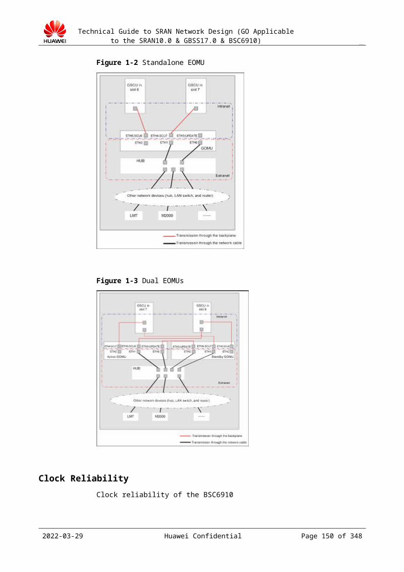
Technical Guide to SRAN Network Design (GO Applicable to the SRAN10.0 & GBSS17.0 & BSC6910)
CONFIDENTIAL
NS refers to the network service control part in the NS protocol. The NS-layer protocol transmits service data unit (SDU) data, manages NS-VC links, shares subscriber data in load-sharing mode, and provides the report of network congestion status indication and the network status report for the upper-layer service module.
BSSGP protocol layerIn the BSS, the BSSGP is the interface between the LLC frame and the RLC/MAC block. In the SGSN, the BSSGP is the interface between the RLC-/MAC-originated information and the LLC frame.The BSSGP provides radio-related data, QoS, and routing information to meet the requirements for subscriber data transmission between the BSS and the SGSN. The BSSGP transmits signaling information and subscriber data, performs flow control for downlink data, blocks and unblocks the BVC, dynamically configures and manages the BVC, and detects errors in interface messages.
In the Gb over IP function, the Gb interface uses the IP protocol to provide the lower-layer transmission service for the NS. The IP transmission module implements the interworking between sub-networks so that the PCU and the SGSN can directly connect to each other (direct connection mode) or connect to each other through the IP transmission network (routing mode).
With the Gb over IP function, IP headers are compressed, and the data on the Gb interface can share the transmission bandwidth to improve the transmission efficiency and save the transmission cost. After the Gb over IP function is used, the Gb interface maintenance commands are simplified, and the maintenance work is simplified.
Generally, the Gb interface adopts IP transmission.
Figure 19-2 shows the logical networking diagram of the embedded PCU.
Figure 19-2 Embedded PCU networking
2023-04-22 Huawei Confidential Page 150 of 258
Technical Guide to SRAN Network Design (GO Applicable to the SRAN10.0 & GBSS17.0 & BSC6910)
CONFIDENTIAL
19.4.2 Networking DesignIn IP networking mode, the PCU and the SGSN can be connected in either of the following modes:
Direct connection (direct connection mode) IP transmission network connection (routing mode)
In Gb over IP direct connection mode, the PCU and the SGSN are directly connected to each other without any intermediate IP network. In this connection mode, a switch can be deployed to provide the layer-2 switching service for the PCU and the SGSN, as shown in Figure 19-1.
Figure 19-1 Direction connection (Gb over IP)
In Gb over IP routing connection mode, the PCU and the SGSN are connected through an intermediate IP network. In this connection mode, routers are used to provide the layer-3 routing service for the PCU and the SGSN, as shown in Figure 19-2.
Figure 19-2 IP transmission network connection (Gb over IP)
Design guide:
Step 1 Determine the networking mode (direction connection networking or layer-2/layer-3 networking) based on the requirements of the customer for the Gb interface networking. The active/standby boards and manual active/standby LAGs+layer-3 router VRRP networking mode is recommended. Do not use the layer-2 networking or direct connection mode.
Step 2 Design the networking reliability of the interface boards based on the capability of the interworking device and the requirements of the customer. The networking reliability of the Gb interface is the same as that of the A interface. The optional modes are active/standby boards, route-based active/standby boards in standalone mode, and route-based boards load sharing in standalone mode. Use the active/standby boards+active/standby ports.
Step 3 If the layer-2/layer-3 networking is adopted, design the layer-2/layer-3 networking reliability and use layer-3 router VRRP+VLANIF to ensure the router reliability.
----End
Design principles:
2023-04-22 Huawei Confidential Page 151 of 258
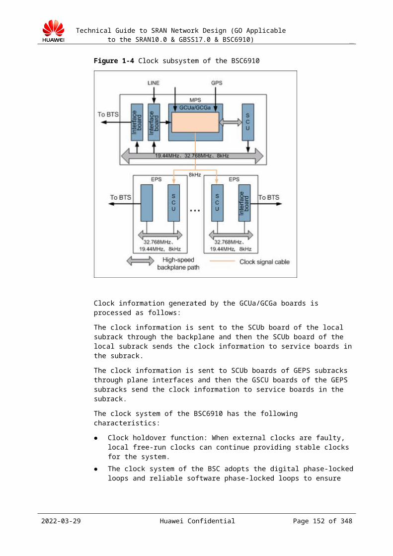
Technical Guide to SRAN Network Design (GO Applicable to the SRAN10.0 & GBSS17.0 & BSC6910)
CONFIDENTIAL
If the IP transmission conditions are met, use IP transmission because the IP transmission bandwidth is sufficient; this facilitates follow-up expansion and SGSN pool implementation.
In IP transmission mode, configure the Gb interface boards to work in active/standby mode.
Connect the active and standby ports to the two VRRP routers respectively.
The typical Gb over IP networking modes are as follows:
Gb interface networking schemes for GBSS15.0 BSC6910:
Promoted schemeNetworking: Pool of active/standby boards+manual active/standby LAGsThe BSC is directly connected to the dual routers through the active/standby ports on the active/standby interface boards. All data is sent and received through the active port. VRRP IP addresses are configured between the dual routers, which function as the next hops of the BSC. Heartbeat messages are transmitted over the trunk between CE1 and CE2. The BSC and the SGSN are deployed in layer-3 networking mode. The SGSN connects to the BSC in loose coupling mode and the BSC can be configured to work in either active/standby mode or load-sharing mode.
Figure 19-1 Typical Gb over IP networking mode (active/standby boards+manual active/standby LAGs)
Ports configured on the two routers CE1 and CE2 and used by the VRRP IP addresses must be configured to layer-2 networking mode, including the ports connecting the BSC and the trunk ports between routers.Bandwidth of trunks must be greater than 50% of the total data volume of the BSC and at least two GE interfaces must be converged.The ports in even-numbered slots of the BSC connect to a high-priority VRRP router, which improves the probability that the same active path is used by the BSC and the router.Ports of the BSC do not support layer-2 exchange, and peer devices are not required to be configured with the STP protocol. If peer devices are configured with the STP protocol, mode of the ports connecting to the BSC must be modified. If peer devices are configured with the RSTP/MSTP, set the port mode to the STP edge port. If peer devices are configured with the STP (802.1D-1998), set the port mode to PortFast. If peer devices do not support the preceding modes, set the port mode to STP Disable.
2023-04-22 Huawei Confidential Page 152 of 258
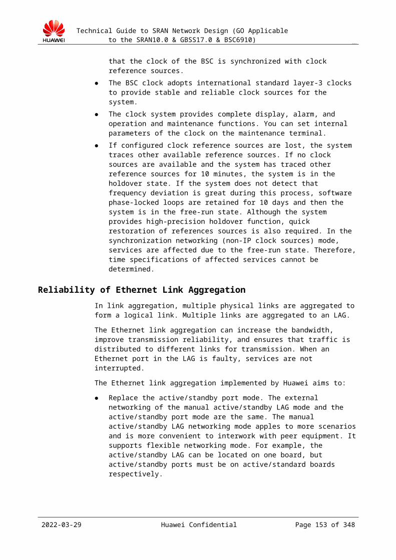
Technical Guide to SRAN Network Design (GO Applicable to the SRAN10.0 & GBSS17.0 & BSC6910)
CONFIDENTIAL
Route configuration examples
Device
Destination IP
Next Hop
Priority
BSC IP311 IP119 Default
CE1 IP150 IP111 Default
CE2 IP150 IP111 Default
Transmission fault detection schemeThe active ports of the active/standby interface boards on the BSC enable two BFD sessions to detect the physical IP addresses of the two routers. The standby ports of active/standby interface boards on the BSC enable an ARP detection session. The BSC performs a BFD detection every 100 ms for three times and performs an ARP detection every 10s for three times. Configure the delay enabling BFD on CE1 and CE2 to avoid service interruption of CE1 and CE2 due to a reset upon power-off.Analysis of the fault switchover mechanism (only on single-fault scenarios)− CE1 is faulty (suspended or powered off): Heartbeat detection on the VRRP port of
CE2 fails and the standby VRRP port of CE2 becomes active. If the BSC sends packets to the SGSN through CE1, the two BFD detections detect faults, manual active/standby LAGs switch over, and the BSC sends packets to the SGSN through CE2. If the BSC sends packets to the SGSN through CE2, only one BFD session on the BSC fails and the active/standby ports are not switched over. After CE1 is faulty, the OSPF re-converges, and the SGSN sends packets to the BSC through CE2. Regardless of whether the BSC sends packets to the SGSN through CE1 or CE2, the BSC and the SGSN exchange messages through CE2. In this case, services are not interrupted and the switchover duration is less than 1s.
− Connection between the BSC and CE1 is faulty: Heartbeat communication on the VRRP ports is correct and the VRRP ports are not switched over. If the BSC sends packets to the SGSN through CE2, only the standby port is faulty, the active/standby ports are not switched over, and the original path remains unchanged. If the BSC sends packets to the SGSN through CE1, it then sends packets through CE2: The two BFD sessions on the active port of the BSC fail, the active/standby ports switch over, and the path of uplink packets of the BSC is BSC => CE2 => CE1 => SGSN. When the active/standby ports switch over, the BSC sends free ARP to update the ARP entries on CE1 and CE2. The SGSN sends packets to the BSC through CE2. In this case, packets are sent to the BSC through CE1 and CE2, services are not interrupted and the switchover duration is less than 1s.
− Connection between two routers is faulty: BFD detection of heartbeat messages on VRRP1 fails and the standby port on CE2 becomes active, then VRRP1 has two active ports. One BFD detection on the active port of the BSC succeeds and the other BFD detection fails, then the active/standby ports are not switched over. If the BSC sends packets to the SGSN through CE1, the original path remains unchanged. If the BSC sends packets to the SGSN through CE1, then the BSC sends packets to the SGSN through CE2: BSC <=> CE2 <=> SGSN. In this case, packet sending from the BSC to the SGSN is not interrupted. If the SGSN sends packets to the BSC through CE1, packet sending is not interrupted. If the BSC sends packets to the SGSN through CE2, packet sending is interrupted. That is, there is 50% probability that packet sending from the SGSN to the BSC may be interrupted (see the following Note).
2023-04-22 Huawei Confidential Page 153 of 258

Technical Guide to SRAN Network Design (GO Applicable to the SRAN10.0 & GBSS17.0 & BSC6910)
CONFIDENTIAL
− Connection between CE1 and the intermediate network is faulty: The OSPF re-converges, services are not interrupted, and the switchover duration is less than 1s.
− Manual switchover of ports on the BSC: VRRP routes and intermediate network routes are not affected. When the active/standby ports switch over, the BSC sends free ARP to update the ARP entries on CE1 and CE2. The SGSN sends packets to the BSC through CE2. In this case, services are not interrupted and the switchover duration is less than 1s.
− Interface boards of the BSC are faulty: The active/standby boards switch over, and the active/standby ports switch over. In this case, services are not interrupted and the switchover duration is 1 to 3s.
− Intermediate network is faulty, which causes a service IP address of the BSC unreachable (rarely occurs): If only one service IP address is configured on the BSC (if only a pair of ports is configured, only one service IP address is configured by default), no redundancy service IP address is available. In this case, all services on this interface are interrupted. In actual commercial deployment, multiple pairs of ports are configured on the BSC to bearer multiple service IP addresses, and one pair of ports can bearer multiple service IP addresses. In this case, if ping detection indicates that the network service virtual connection (NSVC) of an IP address is faulty (service restoration requires 5s x 5 = 25s by default), the BSC allocates subsequent services to another IP address. That is, if the Gb interface on the BSC has only one IP address, all services on this interface are interrupted. If the Gb interface on the BSC has more than one IP address but services on one IP address are interrupted, service access success rate is low within 25s but services restore after 25s. However, because the intermediate network has self-healing function, IP address reachable rarely occurs on VRRP network. This problem can be ignored.
Logical link configuration:NSVL configuration
Device
NSVL IP Addr
UDP Port No
Weight
BSC NSVL 1 IP150 Port 1 100 (see the following Note)
SGSN NSVL 1 IP311 Port 2 100 (see the following Note)
The weight here is not a percentage, the value range is from 1 to 255, and the default value 100 is used (the same for each NSVL). If the bandwidth of intermediate paths is different or the multiple SGSNs are configured on the peer end, modify the value of the weight parameter. Modifying the value of the weight parameter affects the load-sharing effect of this scheme. Therefore, contact R&D engineers if the value of the weight parameter needs to be modified.
NSVC configuration
NSVC BSC IP Addr
BSC UDP Port No
SGSN IP Addr
SGSN UDP Port No
NSVC 1 IP150 Port 1 IP311 Port 2
Optional schemeNetworking: Active/standby boards+dual-active ports
2023-04-22 Huawei Confidential Page 154 of 258
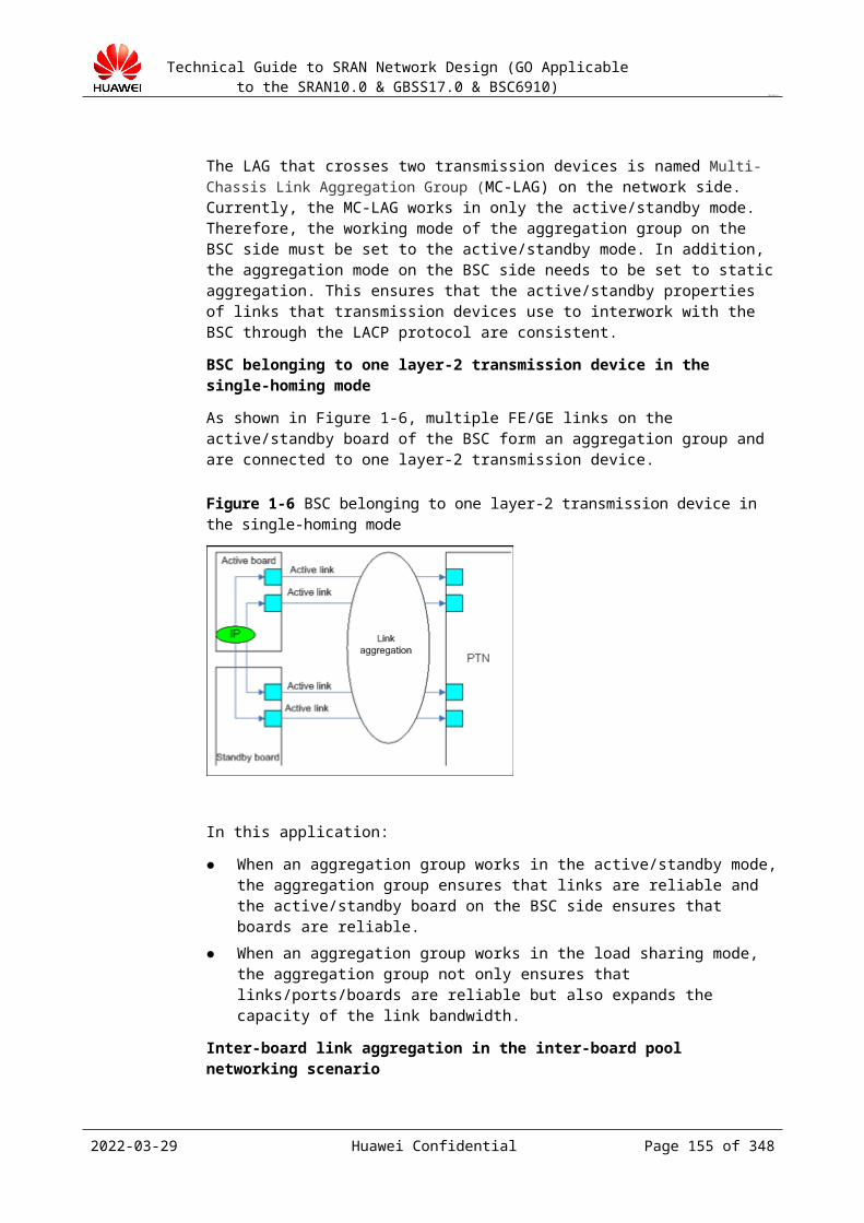
Technical Guide to SRAN Network Design (GO Applicable to the SRAN10.0 & GBSS17.0 & BSC6910)
CONFIDENTIAL
The BSC is directly connected to the dual routers through two independent ports on the active/standby interface boards.Device IP addresses are configured on the logical active board. With the active/standby MGW features of the source IP enabled, the active/standby paths are bound to the outgoing ports of the active/standby boards to achieve active/standby routes of the active/standby boards. Besides, the outgoing port routes of the active/standby boards are configured and active/standby routes are configured for routers, so that the ports of the active/standby boards can protect each other.
Figure 19-2 Typical Gb over IP networking mode (active/standby boards+dual-active ports)
On the bearer network side: Layer-3 router networking is in use and a pair of independent routers is deployed.The Gb interface occupies an Ethernet port. The control plane and user plane are not distinguished, therefore, no VLAN needs to be configured.Configure IP addresses in the same network segment for each sub-interface, which facilitates route combination and simplifies intermediate network route. To facilitate network expansion, service IP addresses of the BSC use logical IP addresses (device IP addresses).Route configuration examples
Device
Destination IP
Next Hop
Priority
BSC
IP311/32 IP110 High
IP331/32 IP130 High
IP311/32 IP130 Low
IP331/32 IP110 Low
CE1IP150/32 IP111 High
IP170/32 IP111 Low
CE2IP150/32 IP131 Low
IP170/32 IP131 High
2023-04-22 Huawei Confidential Page 155 of 258

Technical Guide to SRAN Network Design (GO Applicable to the SRAN10.0 & GBSS17.0 & BSC6910)
CONFIDENTIAL
Local service IP addresses and peer service IP addresses are grouped in two. With route priority configuration, IP addresses in the two groups have different priorities, thereby implementing load-sharing. In addition, backup routes are configured to ensure reliability.Dynamic route protocols (OSPF/ISIS) need to be configured between CE1 or CE2 and intermediate bearer networks. Static routes also need to be configured. In addition, route priorities need to be configured to ensure that the route from CE1 to IP150 has higher priority than the route from CE2 to IP150, and the route from CE2 toIP170 has higher priority than the route from CE1 to IP170. In this case, data is sent to IP150 through CE1 and sent to IP170 through CE2. Detection mechanismThe active port of each board enables two BFD sessions to detect the IP addresses of the two routers. The BSC performs a BFD detection every 100 ms for three times. Configure the delay enabling BFD on CE1 and CE2 to avoid service interruption of CE1 and CE2 due to a reset upon power-off. If BFD is deployed between interface boards and the peer routers, the BSC triggers a switchover of the active/standby gateways in the source IP address routing table. The BSC can detect board faults and if it detects a board fault, the active/standby boards of the BSC switch over, and the logical IP address is migrated to a normal board from the faulty board. Accordingly, the source IP address route mapping the logical IP address is switched between the active/standby gateways.Analysis of the fault switchover mechanism (only on single-fault scenarios)− Connection between the BSC and CE1 is faulty: SBFD detection on the route from
the BSC to IP110 of CE1 fails and the active route whose next hop is IP110 becomes invalid. Then the active/standby routes switch over. The standby route whose next hop is IP130 becomes valid and services migrated to this route. At the same time, the static route that bound to the SBFD on CE1 becomes invalid, and the OSPF re-converges. The next hop of the route between intermediate network to IP150 switches to CE2 from CE1 and the SGSN sends packets to the BSC only through CE2. In this case, services are not interrupted and the switchover duration is less than 1s.
− CE1 is faulty (suspended or powered off): SBFD detection on the route from the BSC to CE1 fails and the active route whose next hop is IP110 becomes invalid. Then the active/standby routes switch over. The standby route whose next hop is IP130 becomes valid and services migrated to this route. At the same time, the BFD for OSPF detection on the intermediate network indicates that CE1 is faulty, and the OSPF re-converges. The next hop of the route between intermediate network to IP150 switches to CE2 from CE1 and the SGSN sends packets to the BSC only through CE2. In this case, services are not interrupted and the switchover duration is less than 1s.
− Main interface boards of the BSC are faulty: In most cases, the BSC can detect board faults and if it detects a board fault, the active/standby boards of the BSC switch over, and the active/standby routes switch over. In this case, services are not interrupted and the switchover duration is less than 1s. In rare cases, the BSC cannot detect board faults. If NSVC detection detects a board fault, the active/standby boards of the BSC switch over. The board switchover triggering mechanism is similar to that when the intermediate network is faulty.
− Intermediate network is faulty, which causes a service IP address of the BSC unreachable (rarely occurs): An NSVC detection takes 15s (3s x 5 = 15s) to 45s (30s + 15s = 45s) (The BSC starts NSVC detection after the Tns-test times out and the system determines that the NSVL is faulty after NS-ALIVE sends an NS-ALIVE-RETRIES message for five times). After the BSC detects an NS-VC fault, the BSC switches the uplink data on this NSVC to a normal NSVC (the BSC replaces only local NSVL) and informs the peer end of the NSVC fault in any of the following ways:
2023-04-22 Huawei Confidential Page 156 of 258
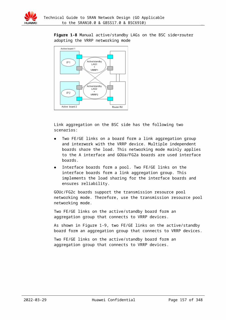
Technical Guide to SRAN Network Design (GO Applicable to the SRAN10.0 & GBSS17.0 & BSC6910)
CONFIDENTIAL
a) The NS STATUS informs the peer end of the local NSVL fault.b) The NS BLOCK blocks the NSVC.c) R-BIT in NS UNITDATA of uplink data is set to 1, requesting the SGSN to
replace the peer NSVL. In this case, data on the faulty path and to be sent to the BSC is sent through a normal NSVL (source NSVL in NS UNITDATA). That is, services over the Gb interface restore after 15 to 45s.
Capacity restriction after the switchover is not taken into consideration.In this scheme, the assumed convergence time of the intermediate network is less than 1s.
Output: Gb over IP networking design
Subrack No.
Slot No.
Board Type
Net Mode
Port Type
Port No.
Configure All
Max Transfer Unit
Auto Negotiation Mode
Port Rate(M)
Flow Control
Duplex Mode
Parameter description:
Board Type: board type. Net Mode: inter-board mode (inter-board active/standby mode, inter-board load-sharing
mode, or standalone mode). Port Type: port type (GE or FE port). Flow Control: whether the flow control is enabled. Max Transfer Unit, Auto Negotiation Mode, Port Rate(M), and Duplex Mode: must
be consistent with those of the directly connected devices.
19.4.3 Bandwidth CalculationUse the GSM NEP tool to calculate the bandwidth.
Output: Gb over IP bandwidth design
BSC Name
Configured BTS
Number active subscribers
Average traffic in BH/sub (bps)
Gb IP throughput (Mbps)
GE Link Number
BoardNumber
IP Segment Number
19.4.4 IP Address PlanningThe BSC interface boards mainly contain the device IP address (logical IP address) and physical port IP address. A physical port can be configured with multiple IP addresses. The following uses the PIU as the common name of the A interface board, Gb interface board, and Abis interface board.
Design principles:
2023-04-22 Huawei Confidential Page 157 of 258
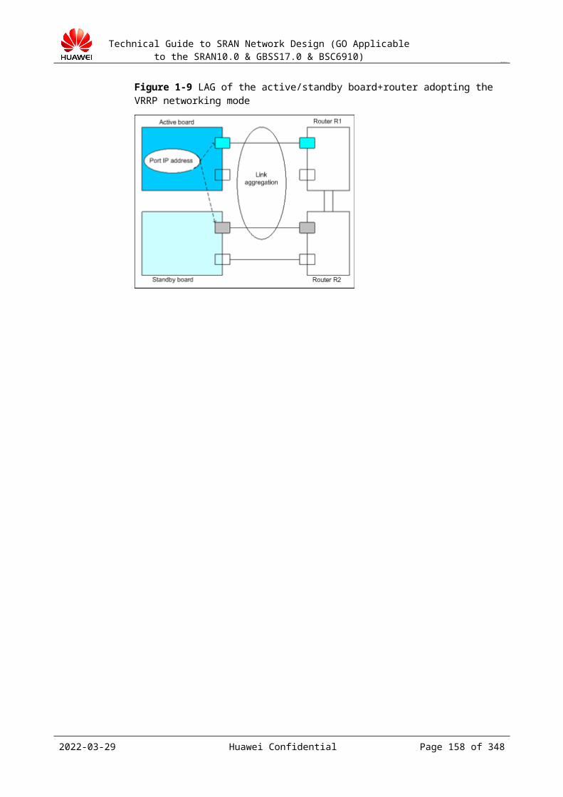
Technical Guide to SRAN Network Design (GO Applicable to the SRAN10.0 & GBSS17.0 & BSC6910)
CONFIDENTIAL
The planned IP addresses must meet the expansion requirements in a certain period (determined by the customer) in future.
The planned IP addresses must facilitate follow-up maintenance. The Gb interface supports VLAN tagging based on the next hop. Add VLAN tags on the
intermediate transmission devices.
Design guide:
Step 1 The device IP address communication mode (recommended) or port IP address communication mode can be used.
Configure and use the port IP address or device IP address. The system automatically identifies the communication mode (port IP communication or device IP communication). The processing of the A interface is the same as the processing of the Abis interface.
Step 2 Allocate port IP addresses and device IP addresses based on the available IP address resources, Gb over IP networking design, and number of boards and number of FE/GE ports calculated in the bandwidth design provided by the customer. Use device IP addresses.
Step 3 In layer-3 networking mode, configure a route on the intermediate router to the device IP address of the BSC.
Principles of IP address planning
The service address and port address are separated on the Gb interface board of the BSC6910. The NSVL uses the service address, and the port address is used to forward data for the communication between the external device and the service address. Therefore, on the router that connects to the BSC, configure a route whose destination address is the service address of the Gb interface and the next hop is the port IP address on the Gb interface board. On the SGSN, configure a route destined for the service address of the Gb interface board.
In active/standby mode, the device IP addresses of the active and standby boards must be the same.
The subnet mask of the device IP address can be 255.255.255.255. If one board is configured with different port IP addresses, the port IP addresses must be
in different network segments. In addition, the port IP addresses and the device IP address must be in different network segments. In active/standby configuration mode, configure the active port IP address. When the ARP detection is enabled on the standby port, configure an IP address for the standby port. In other cases, the standby port does not require an IP address. The IP addresses of the active/standby ports must be in the same network segment.
When you configure a BSC route, the destination IP address must be configured to the network address and cannot be in the same network segment as the port IP address of the board. Otherwise, the destination IP address is invalid.
Network address is a technical term. A network address refers to an address that is used for addressing the peer device when two devices communicate with each other. The network address is the AND result of the peer IP address and subnet mask. For example, the peer IP address is 192.168.80.2 and the subnet mask is 255.255.255.128; the AND result of them is 192.168.80.0 (network address).
When you configure a BSC route, the gateway IP address must be in the same network segment as the port IP address of the board.
The IP address cannot be all 0s or all 255s. The IP address cannot be a loopback address whose network number is 127.x.x.x.
2023-04-22 Huawei Confidential Page 158 of 258

Technical Guide to SRAN Network Design (GO Applicable to the SRAN10.0 & GBSS17.0 & BSC6910)
CONFIDENTIAL
The IP address cannot be the multicast IP address of category D, that is, address in the range of 224.0.0.0 to 239.255.255.255.
The IP address cannot be the reserved IP address of category E, that is, address in the range of 240.0.0.0 to 247.255.255.255.
19.4.5 Routing Planning (Gb over IP)Design principles:
The designed routing solution must facilitate follow-up maintenance. The designed routing solution must facilitate follow-up expansion.
Design guide:
Step 1 Plan BSC routing based on the Gb interface networking design. On the BSC, configure a route to the SGSN. The routing information configured on the BSC includes the destination IP address, subnet mask, and gateway address.
Step 2 On the SGSN, configure a route to the device IP address of the BSC.
Step 3 In layer-3 networking mode, configure a route on the intermediate router to the device IP address of the BSC.
----End
Principles of routing planning:
On the Gb interface board, add a BSC route, that is, plan a route to the service IP address of the SGSN. Destination IP is the network address of the service address of the SGSN. Subnet Mask is the subnet mask of the network where the service address of the SGSN resides. Next Gateway is the IP address of the port (connected to the BSC) on the first router on the way from the BSC to the SGSN; this address must be in the same network segment as the port IP address connected to the BSC.
When the IP subnet configuration mode is dynamic configuration, if the control-plane address and service address of the SGSN are not in the same network segment, configure a route to the network segment of the control-plane address based on the preceding principle. The gateway configuration in control-plane route configuration is the same as the gateway configuration in service-plane route configuration.
Output: Gb over IP routing design
NE name
Board Type
Board Number
Port ID
SGSN Name
Destination IP
Subnet Mask
Next Gateway
Parameter description:
Destination IP Address: network IP address of the destination IP address of the peer SGSN (destination of the data from the Gb interface board of the BSC). If the peer SGSN does not have a device IP address (logical IP address), this parameter indicates the network IP address of the port IP address. The network IP address is obtained by performing the AND operation on the device IP address (or port IP address if no device IP address is available) of the SGSN and the subnet mask.
Subnet Mask: subnet mask of the IP address of the peer SGSN.
2023-04-22 Huawei Confidential Page 159 of 258
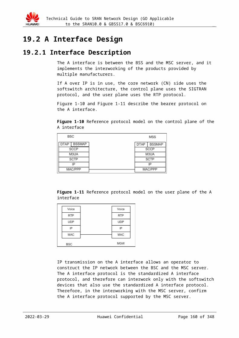
Technical Guide to SRAN Network Design (GO Applicable to the SRAN10.0 & GBSS17.0 & BSC6910)
CONFIDENTIAL
Gateway: port IP address of the device directly connected to the outgoing port of the Gb interface board on the BSC. This IP address must be in the same network segment as the IP address of the outgoing port of the Gb interface board.
Route Priority: route priority, and the default value is 1.
19.4.6 QoS Design (Gb over IP)Design principles:
Port link detection
The BFD detection and ARP link detection cannot be enabled at the same time on the interface board.
One port can be configured with only one detection mode. If a port is not configured with the BFD detection or ARP link detection, the physical-layer detection is adopted by default.
The following detection modes are supported: BFD detection on the active port and ARP detection on the standby port (the standby port does not support BFD detection), ARP link detection on the active and standby ports, BFD detection on the active port and physical-layer detection on the standby port, ARP detection on the active port and physical-layer detection on the standby port, and physical-layer detection on the active and standby ports.
Design guide:
Step 1 Design the port QoS attribute parameters based on the capability of the interworking device.
Step 2 Determine the port link detection mode (BFD detection, ARP link detection, or physical detection) based on the capability of the interworking device. The physical detection is supported by default and does not require configuration.
----End
Output: Gb over IP QoS design
ARP link detection
Subrack No.
Slot No.
Port No.
IP Address Index
Peer IP Address
Arp Retry Attempts
Arp Timeout
VLAN Flag
VLAN ID
Peer IP Address of the Standby Board
Parameter description:
Port No.: port number of the Abis interface board that requires the physical link detection.
IP Address Index: IP address index. The system supports the configuration of multiple IP addresses for a port.
Peer IP Address: port IP address of the device that is directly connected to the physical port.
Arp Retry Attempts: number of ARP detection times in a period. The default value is 3.
2023-04-22 Huawei Confidential Page 160 of 258
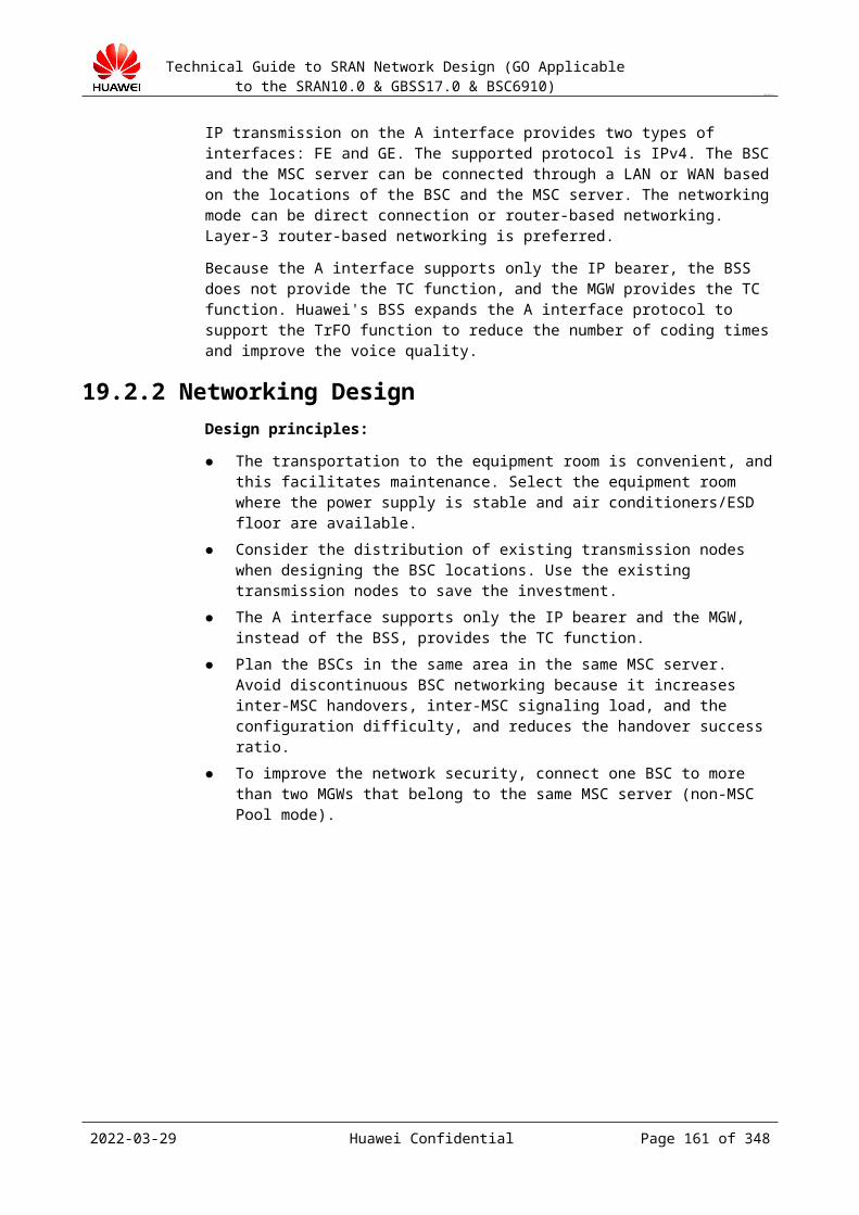
Technical Guide to SRAN Network Design (GO Applicable to the SRAN10.0 & GBSS17.0 & BSC6910)
CONFIDENTIAL
ARP Timeout: ARP response timeout interval (after an ARP request is sent) in the ARP detection. The default timeout interval is 3 seconds. Use the default value 3. The software has a bug, and do not change the value.
VLAN Flag: whether VLAN tags are added to ARP packets when the BSC implements ARP detection. If the VLAN function is enabled on the device port that possesses the gateway IP address of the route configured on the port, this parameter must be enabled, and the VLAN ID must be the same as the VLAN ID configured for the device port that possesses the gateway address; otherwise, the route is unreachable.
VLAN ID: VLAN ID in the ARP detection packets when VLAN Flag is set to Enable. Peer IP Address of the Standby Board: physical IP address of the peer port directly
connected to the physical port of the standby board.
BFD detection
Subrack No.
Slot No.
Port No.
IP Address Index
Peer IP Address
MinTxInterval(ms)
MinRxInterval(ms)
Detect Mult
Peer IP Address of the Standby Board
Parameter description:
Peer IP Address: peer IP address in the BFD session. The BFD detection supports only the next hop detection. Therefore, the peer IP address in the BFD session is the port IP address of the device that is directly connected to the port.
MinTxInterval(ms): minimum interval between the BFD control packets that the local system sends.
MinRxInterval(ms): minimum interval between the BFD control packets that the local system receives.
Detect Mult: number of detection times, that is, the link is considered disconnected after the detection fails for the specified number of times.
For details about the other parameters, see the parameter description in "ARP link detection."
19.4.7 Configuration Principles One BSC can connect to multiple SGSNs. One BSC can be configured with multiple network service entities (NSEs). NSEs belong to the same SGSN must be different.
One SGSN can correspond to multiple NSEs in a BSC, but all point-to-point BSSGP virtual connections (PTP BVCs) in an NSE can provide services only for one SGSN.
One cell corresponds to one PTP BVC (except for the SGSN pool scenario). One BSC can belong to different SGSN cells.
19.4.8 Interface InterworkingThe Gb interface interworking needs to be negotiated with the SGSN. In the negotiation, prepare the template of interface interworking parameters, parameter description, networking diagram, and precautions to improve the interworking efficiency.
2023-04-22 Huawei Confidential Page 161 of 258
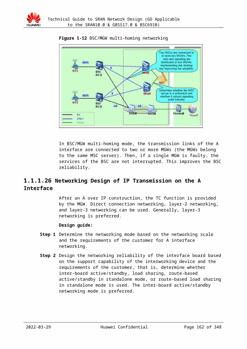
Technical Guide to SRAN Network Design (GO Applicable to the SRAN10.0 & GBSS17.0 & BSC6910)
CONFIDENTIAL
If the Gb interface adopts the IP protocol, the Gb interface link needs to be configured with the NSE, local NSVL, remote NSVL, and PTP BVC objects.
Table 19-1 Parameters of Gb interface link configuration
Object Description Recommended Configuration
NSE On the BSSGP layer, the NSE functions as a BVC collection; on the NS layer, the NSE functions as an IP NSVC collection. An NSEI uniquely identifies an NSE. The NSEIs configured on the BSC are the same as the NSEIs configured on the SGSN.Select the IP protocol for the NSE. Configure the local and remote NSVL objects.
Non-SGSN pool networking: Configure each BSC with an NSE (or multiple NSEs).SGSN pool networking: The number of NSEs is equal to the number of SGSNs in the SGSN pool to which the BSC belongs. The NSEs on the BSC map the NSEs on the SGSN based on the one-to-one relationship, that is, the NSEs at the two ends must be consistent.
Local and remote NSVLs
The local NSVL determines the location information about the Gb interface board, establishes mappings between NSEs and device IP addresses/port numbers, and determines the ports through which the NSE cell data is transmitted. The remote NSVL establishes mappings between NSEs and device IP addresses/port numbers on the SGSN side and determines the ports through which the NSE cell data is transmitted.The NSVL is used in Gb over IP mode, and it is equivalent to the NSVC in Gb over FR mode.On the IP network, an IP NSVC is uniquely identified a quadruple of the local IP address, local port number, peer IP address, and peer port number.
Each NSE must be configured with at least two NSVLs.The number of NSVLs must be equal to or larger than the number of physical transmission links. Use logical IP addresses (device IP addresses) as the IP addresses of NSVL.
PTP BVC The PTP BVC establishes the point-to-point virtual connection on the BSSGP layer.Each cell corresponds to one PTP BVC.
Non-SGSN pool networking: One cell corresponds to one PTP BVC.SGSN pool networking: A PTP BVC must be configured between each cell and each SGSN in the Pool.
2023-04-22 Huawei Confidential Page 162 of 258
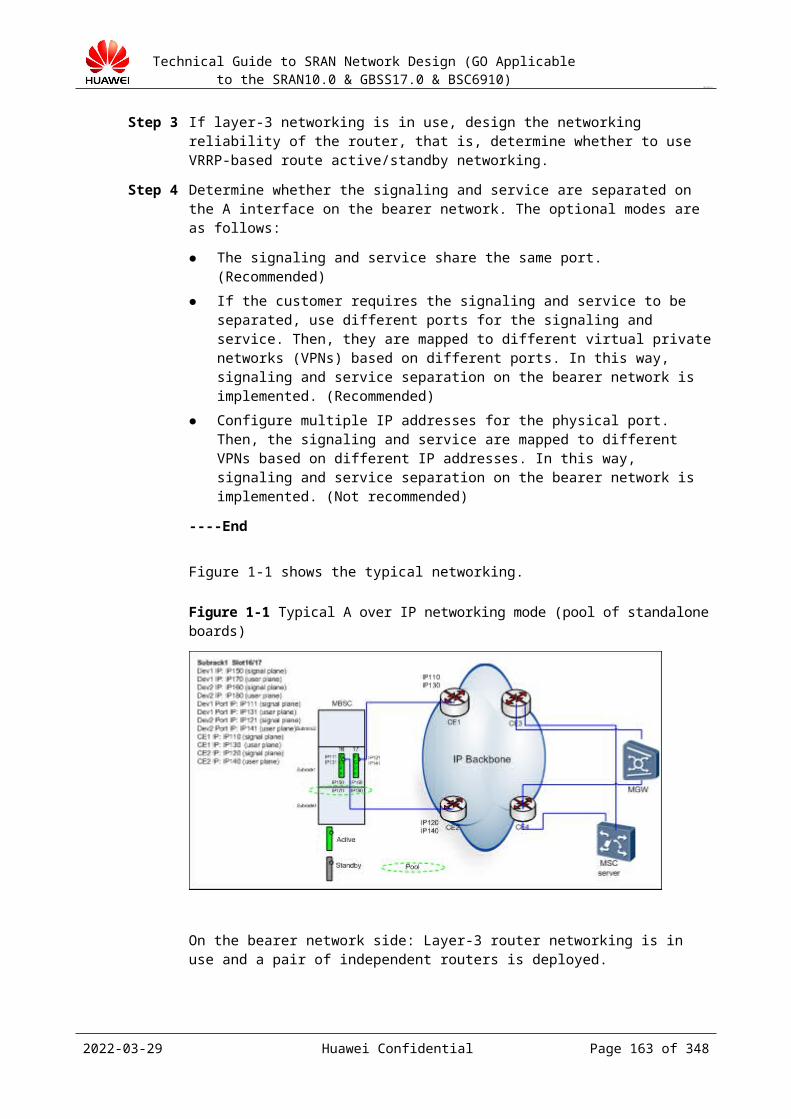
Technical Guide to SRAN Network Design (GO Applicable to the SRAN10.0 & GBSS17.0 & BSC6910)
CONFIDENTIAL
Figure 19-2 shows the logical connection at the NS layer and BSSGP layer between the BSC and the SGSN.
Figure 19-2 Logical connection between the NS layer and the SSGP layer
As shown in Figure 19-2, on the BSSGP layer, the NSE functions as a BVC collection (equivalent to a cell collection); on the NS layer, the NSE functions as an IP NSVC group (IP NSVC collection). The NS layer provides data transmission channels for the BSSGP layer. The channel used to transmit the data of the cells in the same NSE must be an IP NSVC in the IP NSVC collection of the NSE. The channel selection principle is that the traffic between IP NSVCs is balanced.
In Gb over IP mode, the user needs to configure IP NSVCs by using the local NSVL and remote NSVL objects
Key interworking parameters in IP networking mode:
Table 19-1 Gb over IP interworking parameters
Parameter DescriptionNSEI Value range: 0 to 65534. It is the same as the
NSEI on the SGSN.
Subnet configuration mode Static or Dynamic.
Service address of the SGSN It indicates the IP address and subnet mask of the remote NSVL.
Service address of the BSC (device IP address)
It indicates the IP address and subnet mask of the local NSVL. The device must inform the SGSN of this parameter.
IP address on the server (control plane) and UDP port number on the server
This parameter needs to be negotiated when
2023-04-22 Huawei Confidential Page 163 of 258
Technical Guide to SRAN Network Design (GO Applicable to the SRAN10.0 & GBSS17.0 & BSC6910)
CONFIDENTIAL
(control plane) of the SGSN the subnet configuration mode is Dynamic.
Address and UDP port number of the remote NSVL
This parameter needs to be negotiated when the subnet configuration mode is Static.
IP address and UDP port number of the local NSVL
The device needs to inform the SGSN of this parameter when the subnet configuration mode is Static.
Port IP address IP address of the port on the board. The routing gateway IP address on the SGSN side is the port IP address of the BSC when the networking mode is direct connection.
In Gb over IP mode, the NSVL configuration modes are static configuration and dynamic configuration. In static configuration mode, the remote NSVL is configured by using the local maintenance terminal (LMT) or man-machine language (MML) commands. In dynamic configuration mode, the remote NSVL is obtained from the SGSN by using the subnet service process (SNS process) in the 48018 protocol. The main differences between the dynamic configuration process and the static configuration process are as follows:
When you configure the NSE in dynamic configuration mode, set Subnet configure mode to Dynamic and configure Server IP and Server UDP Port. Server IP and Server UDP Port specify the interface corresponding to the remote NSVL (used to communicate with the BSC) on the SGSN. In static configuration mode, set Subnet configure mode to Static.
In static configuration mode, configure the remote NSVL, whereas in dynamic configuration mode, the remote NSVL is not required.
Local NSVL:
NSVLI: indicates the local NSVL ID. The value range is 0 to 65534. It needs to be negotiated with the SGSN.
NSEI: indicates the NSE ID. The value range is 0 to 65534. The NSEs of the same SGSN are numbered in a unified manner. This parameter needs to be negotiated with the SGSN.
IP: indicates the IP address. The value must comply with IPv4. It needs to be negotiated with the SGSN.
UDPPN: indicates the UDP port number. The value range is 0 to 65534. It needs to be negotiated with the SGSN.
Remote NSVL:
NSVLI: indicates the local NSVL ID. The value range is 0 to 65534. It needs to be negotiated with the SGSN.
NSEI: indicates the NSE ID. The value range is 0 to 65534. The NSEs of the same SGSN are numbered in a unified manner. This parameter needs to be negotiated with the SGSN.
IP: indicates the IP address. The value must comply with IPv4. It needs to be negotiated with the SGSN.
UDPPN: indicates the UDP port number. The value range is 0 to 65534. It needs to be negotiated with the SGSN.
2023-04-22 Huawei Confidential Page 164 of 258
Technical Guide to SRAN Network Design (GO Applicable to the SRAN10.0 & GBSS17.0 & BSC6910)
CONFIDENTIAL
An NSE specifies a network service entity; it is a collection of the BVC and the IP NSVC. Determine a protocol type Gb over IP for an NSE. In IP mode, configure the local and remote NSVL objects.
19.4.9 Interworking InstancesGb over IP instances
Design the basic Gb over IP parameters that need to be negotiated with the SGSN based on the Gb over IP networking design and IP address planning. The basic negotiation parameters are as follows:
Table 19-1 SGSN node parameters
SGSN Node Parameter
Description
SGSN Node ID It indicates the SGSN number.
Configure Capacity It indicates the number of subscribers that can access the NSE. In the case that one BSC can connect to multiple SGSNs, a subscriber determines the SGSN to access based on the NSE capacity.
SGSN Management Status It indicates that when an MS accesses the network initially, the MS selects the SGSN randomly, causing some SGSNs overloaded. The three SGSN management states are uninstalled, normal, and prohibited. In the uninstalled state, the SGSN cannot provide access for new users; in the normal state, the SGSN can be used normally; in the prohibited state, the SGSN cannot be used.
Table 19-2 NSE attribute parameters
NSE Attribute Parameter
Description
NSE Identifier It indicates the NSE ID. An NSE manages a group of NSVCs.
Subrack Number It indicates the number of the subrack where the end-to-end communication NSE is located.
Subnet protocol type In Gb over IP mode, the Gb interface is connected to the IP network. The IP network in Gb over IP mode takes the place of the FR connections in Gb over FR mode. In Gb over IP mode, the subscriber data and signaling data of the Gb interface are transmitted in UDP packets. In Gb over IP mode, the functions of the protocol stacks of the NS and upper layers are completely the same as the functions in Gb over FR mode.
Subnetwork Configure Mode
It indicates the IP subnet configuration mode. The two optional modes are static configuration and dynamic configuration. In static configuration mode, the remote NSVL can be configured on the LMT. In dynamic configuration mode, the remote NSVL can be obtained from the SGSN by
2023-04-22 Huawei Confidential Page 165 of 258
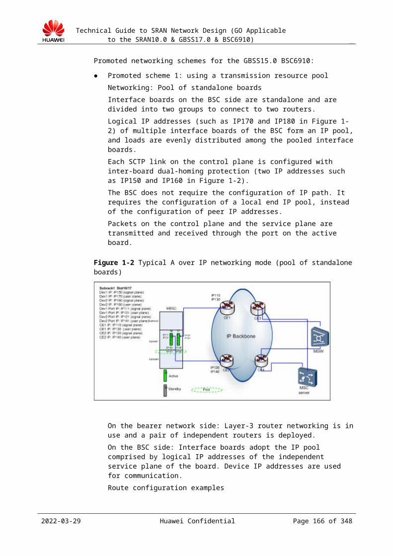
Technical Guide to SRAN Network Design (GO Applicable to the SRAN10.0 & GBSS17.0 & BSC6910)
CONFIDENTIAL
NSE Attribute Parameter
Description
using the protocol process.
Server IP It indicates the IP address of the SGSN. If the IP subnet configuration mode is static configuration, the server IP address is not required. If the IP subnet configuration mode is dynamic configuration, configure the server IP address.
Server UPD Port It indicates the UDP port number of the SGSN. If the IP subnet configuration mode is static configuration, the server UDP port number is not required. If the IP subnet configuration mode is dynamic configuration, configure the server UDP port number.
RIM Support It indicates whether the NSE supports the RIM function. If the RIM function is enabled, the SIGBVC needs to be reset. The RIM function can be implemented only if the SGSN also supports the RIM function. Default value: NO.
PFC Support It indicates whether the NSE supports the PFC function. If the PFC function is enabled, the SIGBVC needs to be reset. The PFC function can be implemented only if the SGSN also supports the PFC function. Default value: NO.
Table 19-3 Local NSVL parameters (configured on the Gb interface board)
Local NSVL Parameter
Description
Local NSVL ID It indicates the NSVL ID on the BSC side. An NSVL ID uniquely identifies an NSVL. An NSVL is a network service virtual link.
NSE Index It indicates the NSE index.
IP Address It indicates the IP address in the dotted decimal format of the Gb interface board.
UDP Port It indicates the UDP port number. It must be consistent with the UDP port number configured on the SGSN.
Signaling load weight It indicates the signaling data load sharing. In Gb over IP mode, the uplink signaling message load sharing involves the selection of the local IP endpoint and the remote IP endpoint. The protocol does not describe the selection of the local IP endpoint in detail, and this process is simplified. All the available local signaling endpoints are evenly polled to select a local signaling endpoint.
User Data load weight The service data load sharing involves the selection of the local IP endpoint and the remote IP endpoint. All local IP endpoints are polled to select a local IP endpoint. The value range is 0 to 255.
2023-04-22 Huawei Confidential Page 166 of 258

Technical Guide to SRAN Network Design (GO Applicable to the SRAN10.0 & GBSS17.0 & BSC6910)
CONFIDENTIAL
Table 19-4 Remote NSVL parameters
Remote NSVL parameter
Description
Remote NSVL ID It indicates the NSVL ID on the SGSN side. An NSVL ID uniquely identifies an NSVL.
NSE Index It indicates the NSE index.
IP Address It indicates the IP address of the remote NSVL. You need to specify the peer IP address only when configuring the remote NSVL.
UDP Port It indicates the UDP port number. It must be consistent with the UDP port number configured on the SGSN.
Signaling load weight It indicates the signaling data load sharing.In Gb over IP mode, the uplink signaling message load sharing involves the selection of the local IP endpoint and the remote IP endpoint. The protocol does not describe the selection of the local IP endpoint in detail, and this process is simplified. All the available local signaling endpoints are evenly polled to select a local signaling endpoint.
User Data load weight It indicates the service data load sharing. The service data load sharing involves the selection of the local IP endpoint and the remote IP endpoint. All local IP endpoints are polled to select a local IP endpoint. The value range is 0 to 255.
If the NSE attribute Subnet configure mode is set to Static, configure the remote NSVL; if it is set to Dynamic, do not configure the remote NSVL.
Table 19-5 PTP BVC attribute parameters
PTP BVC Attribute Parameter
Description
NSE Index It indicates the NSE ID.
PTP BVC Identifier It identifies a unique PTP BVC with NSE.
Cell Name It indicates the BSC cell name.
Table 19-6 SGSN attribute parameters:
SGSN Attribute Parameter
Description
SGSN Name It indicates the SGSN name.
2023-04-22 Huawei Confidential Page 167 of 258
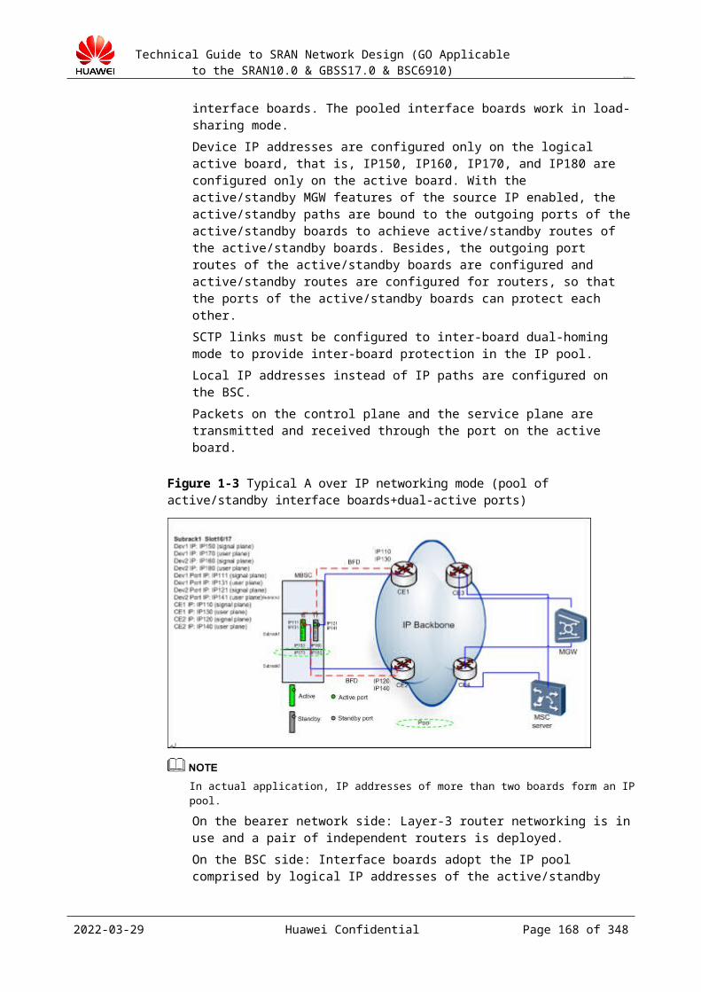
Technical Guide to SRAN Network Design (GO Applicable to the SRAN10.0 & GBSS17.0 & BSC6910)
CONFIDENTIAL
IP Address It indicates the IP address of the SGSN.
In active/standby mode, the IP address of the standby board must be in the same network segment as the IP address of the active board.
19.5 Abis Interface Design19.5.1 Interface Description
The Abis interface in an internal interface. The BTS that are provided by different manufacturers cannot interwork through the Abis interface.
Therefore, in terms of Abis interface interworking, the BSC6910 can interwork only with Huawei's BTS. The BSC6910 supports only BTS3012 and BTS3900, but does not support the co-locate deployment of BTS3012 and BTS3900, or the BTSs of BTS3X serials.
The protocols and standards that the Abis interface complies with are as follows:
Basic principles of the Abis interface: 3GPP 48.052 Physical layer: 3GPP 48.054 Data link layer: 3GPP 48.056 Layer 3 signaling procedure: 3GPP 48.058 O&M message transfer mechanism: 3GPP 52.021 BSC code converter/rate adaptation in-band control protocol: 3GPP 48.060
The Abis interface of the GBSS15.0 BSC6910 supports IP over FE/GE, and TDM over STM-1. The interface bandwidth and networking mode are closely related to the interface type.
IP transmission mode
Basic principle: UDP/IP bears the CS and PS service, signaling, and O&M messages.
Implementation method:
Packet interfaces boards are added to the BTS and the BSC. On the Abis interface, the PS and service service/signaling messages are transmitted in IP over FE/GE mode.
Each BTS is configured with an independent logical IP address. Each CS service channel, RSL, OML, and ESL is allocated with a UDP port number. For the PS service, each TRX is allocated with a UDP port number.
On the BSC side, a fixed UDP port number is used, and the UDP port number on the BTS side is used to distinguish CS and PS signaling/O&M messages.
2023-04-22 Huawei Confidential Page 168 of 258
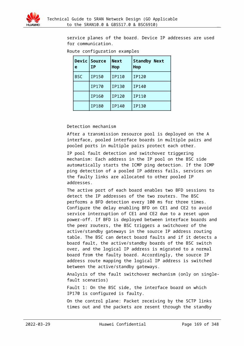
Technical Guide to SRAN Network Design (GO Applicable to the SRAN10.0 & GBSS17.0 & BSC6910)
CONFIDENTIAL
Figure 19-1 Abis over HDLC interface protocol
19.5.2 Networking Design
19.5.2.1 Basic Procedure1. Transmission mode selection
Abis over TDM Abis over IP
2. Transmission type selection
STM-1 IP or FE
3. Networking design Design the networking based on the site configuration, number of transmission resources of the operator, and distribution of the transmission backbone network. For the operator who provides sufficient TDM transmission
resources, use the simple star networking. For some VIP BTSs where transmission resources are sufficient
and the security requirements are high, use the ring networking.
For the operator who purchases the BTS local exchange and Flex Abis functions and adopts TDM transmission, use the star or chain (determined by the technical personnel based on the onsite conditions) networking.
19.5.2.2 Transmission ModeThe Abis interface supports two transmission modes: Abis over TDM and Abis over IP.
2023-04-22 Huawei Confidential Page 169 of 258
Technical Guide to SRAN Network Design (GO Applicable to the SRAN10.0 & GBSS17.0 & BSC6910)
CONFIDENTIAL
Abis over TDMIn Abis over TDM mode, the Abis interface adopts the traditional TDM mode for transmission. In this mode, the Abis interface board of the BSC6910 is the POUc, and the SDH/PDH network is deployed between the BSC and the BTS to provide the transmission service.Advantages: The networking solution is proven with the perfect QoS guarantee mechanism. This mode is secure and reliable. The operator can fully use the existing PDH/SDH transmission resources.Disadvantage: The cost of this solution is higher than the cost of the IP transmission solution.
Abis over IPIn Abis over IP mode, layer 2 of the protocol stack of the Abis interface complies with the IP protocol. The Abis interface board of the BSC6910 is the FG2c/GOUc/EXOUa/FG2d/GOUd, and the IP network is deployed between the BSC and the BTS to provide the transmission service.Advantages: The bandwidth is sufficient; the cost is low; the evolution capability is high.Disadvantage: The QoS is difficult to guarantee.The following is the design guide to the Abis over IP mode:
Design guide:
Step 1 Determine the networking mode (direction connection networking or layer-2/layer-3 networking) based on the requirements of the customer for the Abis interface networking and the adopted transmission backbone network (MSTP and MPLS/IP). Use the active/standby boards+manual active/standby LAGs (Pool of single IP address)+layer-3 router networking mode. Do not use the layer-2 or direct connection mode.
Step 2 If the layer-2/layer-3 networking mode is used, determine the transmission mode. The optional transmission modes are MSTP transmission, layer-2/layer-3 data network transmission, satellite link transmission, and XDSL transmission.
Step 3 Design the networking reliability of the interface board based on the capability of the interworking device and the customer requirements. Use the mode of active/standby boards+manual active/standby LAGs (Pool of single IP address) for the Abis interface networking, and do not use the load sharing+router VRRP mode.
Step 4 If the layer-3 data transmission networking mode is used, determine whether to enable the router to adopt VRRP+VLANIF to improve the reliability in the mode of active/standby boards.
----End
The Abis over IP mode supports two application scenarios: direct connection and switch/router networking.
Figure 19-1, Figure 19-2, and Figure 19-3 show the typical networking diagrams.
2023-04-22 Huawei Confidential Page 170 of 258

Technical Guide to SRAN Network Design (GO Applicable to the SRAN10.0 & GBSS17.0 & BSC6910)
CONFIDENTIAL
Figure 19-1 TDM networking when the Abis interface adopts STM-1 transmission
Figure 19-2 IP networking when the Abis adopts MSTP transmission
Figure 19-3 IP networking when the Abis adopts data network transmission
19.5.2.3 Networking Design (TDM)The main BTS networking types are chain, star, ring, and tree.
2023-04-22 Huawei Confidential Page 171 of 258
Technical Guide to SRAN Network Design (GO Applicable to the SRAN10.0 & GBSS17.0 & BSC6910)
CONFIDENTIAL
Figure 19-1 BTS networking diagram
Each networking type has its own advantages and disadvantages. Configure the networking based on the requirements of the operator based on the following principles:
Star networking Advantages: The network structure is simple; expansion is convenient; the reliability is high. If one BTS is faulty, the other BTSs are not affected. Therefore, the star networking is widely used. However, for small-scale BTSs, the transmission usage of the star networking is low. The timeslot consolidation device can be used to address this issue.
Chain networking If the coverage area is in the form of a band (for example, the highway), and the traffic in the coverage area is light, the chain networking can be used because if the star networking is used in such a coverage area, transmission resources are wasted. In chain networking, the BTSs are cascaded. A BTS on a cascading link processes only its own timeslots and transparently transmits the timeslots of downstream BTSs.The clock preciseness decreases with the number of cascading levels, and this may degrade the BTS performance. Therefore, the number of cascading levels cannot be too large. Disadvantage: Expansion is inconvenient, and the reliability is low. If a transmission fault occurs on a BTS in the chain, the services of the downstream BTSs are affected.
Tree networking In tree networking mode, the BTS that is directly connected to the BSC is the parent BTS, and the BTSs subordinated to the parent BTS are children BTSs. The parent BTS completes timeslot interchange of the children BTSs. Timeslot interchange can be controlled by using the LMT.The tree networking combines the characteristics of the star networking and chain networking, and the reliability of the tree networking is between these two networking modes. The disadvantage is that the structure is complicated, which causes inconvenience for expansion and maintenance.
Ring networking The ring networking is a special chain networking. In normal cases, the BTSs form an ordinary chain, and the last BTS is connected back to the BSC. In this way, a ring is formed. If a transmission fault occurs on a BTS on the ring, the networking mode of the upstream BTSs before the faulty BTS does not change, and the
2023-04-22 Huawei Confidential Page 172 of 258

Technical Guide to SRAN Network Design (GO Applicable to the SRAN10.0 & GBSS17.0 & BSC6910)
CONFIDENTIAL
downstream BTSs after the faulty BTS form a new chain in a reverse manner.The reliability is high, but the transmission resource cost is high. It is recommended for some VIP sites.
Star networking and configuration principles− In star networking mode, any TDM BTS is directly connected to the Abis TDM
interface board (POUc) on the BSC through fiber and does not need another BTS for transfer.
− A transmission-optimized BTS is directly connected to the Abis interface board on the BSC through fiber and does not need another BTS for transfer.
− An IP BTS is connected to the router or switch through one or two FE ports and does not need another BTS for forwarding.
Chain networking and configuration principlesIn chain networking mode, each BTS receives information from the upper-level BTS and transmits the information to the lower-level BTS in cascading mode. The chain networking mode can be single-chain cascading or multi-chain cascading:− Single-chain cascading: If the total number of cascading BTSs is less than 5 and the
total number of TRXs is less than 15, the single-chain cascading mode can be used.− Multi-chain cascading: If the total number of cascading BTSs is less than 5 and the
total number of TRXs is greater than 15, the multi-chain cascading mode can be used. A BTS supports a maximum of eight E1 ports; therefore, the multi-chain cascading mode supports a maximum of eight active/standby links.
− If the number of TRXs of each BTS is great (greater than six), the chain networking mode can be used. The number of TRXs allowed in multi-chain cascading mode is greater than that in single-chain cascading mode.
− TDM BTSs are directly connected to the Abis interface board on the BSC through fiber.
Tree networking and configuration principles− If two BTSs are subordinated to another BTS, the networking mode is the tree
networking mode. The tree networking mode combines the characteristics of the star and chain networking modes.
− If a BTS adopts the single-chain mode to connect to the Abis interface board directly, this root can connect to a maximum of 15 TRXs. Due to the E1 port restriction (each TMU provide only eight E1 ports) of the TMU on the BTS, each root can possess a maximum of seven branches (in the case that two TMUs that work in active/standby mode are configured for the root BTS).
− If a BTS adopts the multi-chain mode to connect to the Abis interface board directly, the number of TRXs that can connect to this root is determined by the number of E1 timeslots. Due to the E1 port restriction (each TMU provide only eight E1 ports) of the TMU on the BTS, each root can possess a maximum of six branches (in the case that two TMUs that work in active/standby mode are configured for the root BTS).
− TDM BTSs are directly connected to the Abis interface board on the BSC through E1 links.
Ring networking and configuration principlesIn ring networking mode, the Abis interface board and the BTSs form a ring, as shown in Figure 19-1. In normal cases, the BTSs form a ring network. If a BTS is faulty, the networking mode of the upstream BTSs before the faulty BTS does not change, and the
2023-04-22 Huawei Confidential Page 173 of 258
Technical Guide to SRAN Network Design (GO Applicable to the SRAN10.0 & GBSS17.0 & BSC6910)
CONFIDENTIAL
downstream BTSs after the faulty BTS form a new chain in a reverse manner. Compared with the chain networking mode, the ring networking mode is more robust. If the ring is disconnected at a point, it is automatically split into two chains, and the BTSs before and after the faulty point can work properly.− In ring networking mode, if the BSC6910 is connected to BTSs through
active/standby Abis interface boards, the ports of the Abis interface may be insufficient. In this case, configure the Abis interface boards of the BSC6910 to work in non-active/standby mode. Then, the interface boards are counted in single-board mode instead of active/standby mode, that is, each interface board is counted (not recommended).
− One ring supports the BTS cascading of a maximum of five levels. Each BTS on the ring can support tributary BTSs. The BTSs on the ring and their tributary BTSs form a tree network. This networking mode is the same as the tree networking mode. The number of BTS cascading levels between a tributary BTS and the BSC cannot exceed five.
OML backup networkingPrinciples:On Huawei's 2G site, the OML link can be configured only on the timeslot of port 0. If the OML link fails, the services of the entire site are interrupted. Therefore, in the V900R011 version, the OML backup function is planned.If the user uses the OML backup function when configuring the BTS, the BSC configures an OML link on timeslot 31 of port 0 and port 1. After the BTS is reset, the BTS attempts to establish a link on the two ports one by one. Once the OML link is established on either port, this OML link is always used unless the BTS is reset or the OML link is disconnected. If the established OML link is disconnected, the BTS automatically switches to the other port and attempts to establish a link on that port. If the link is established successfully, the BSC triggers an OML link switchover and switches the related ESL/EML links to the port where the currently available OML link is located.In the OML backup function, the processing of OML/EML/ESL links is similar to the processing on the ring network, that is, link switchovers can be performed. However, the processing of carrier RSLs, service channels, idle timeslots, and monitoring timeslots is different from the processing on the ring network, that is, switchovers are not performed. In other words, for port 0 and 1 of the BTS, if the port where the currently available OML link is established is faulty, all the carriers, channels, idle timeslots, and monitoring timeslots configured on this port become invalid, whereas the OML/ESL/EML links can be switched over to the other port to ensure that the BTS is not out-of-service and that the normal port can provide services.Restrictions:− The new BTS types (such as the 3900 series) later than the BTS3012 series of
double-density BTSs support this function.− Only the TDM (including the 16 kbit/s and Flex Abis scenarios) supports this
function. The IP networking mode does not support this function.− The OML backup function is mutually exclusive with the ring network and Abis
bypass functions.− OML backup can be implemented only between port 0 and port 1 in the primary
cabinet group and cannot be implemented between other ports or between the primary cabinet group and the secondary cabinet group.
− The two mutually backup OML links (including EML/ESL) between the BSC and the BTS cannot be located on the same E1/T1 (or on the same E1/T1 on the upper-level
2023-04-22 Huawei Confidential Page 174 of 258

Technical Guide to SRAN Network Design (GO Applicable to the SRAN10.0 & GBSS17.0 & BSC6910)
CONFIDENTIAL
BTS). That is, if the upper-level BTS has only one E1/T1 connected to the BSC, the OML backup function can be used only if either of the following conditions is met:− A secondary link to the upper-level BTS is added.− A secondary link (directly connected to the BSC) to the lower-level BTS is added.
Figure 19-2 and Figure 19-3 show the typical networking diagrams.
Figure 19-2 Two E1s connected to different interface boards
Figure 19-3 Two E1s connected to different ports on the same interface board
The reliability of the networking mode where the E1s of a BTS are connected to two pairs of interface boards is high. Therefore, use this mode.
However, do not connect the E1s of the BTS to the interface boards in different subracks.
19.5.2.4 Networking Design (IP)Interface networking schemes for GBSS15.0:
Promoted schemeNetworking: Pool of active/standby boards+manual active/standby LAGs+single IP addressThe BSC is directly connected to the dual routers through the active/standby ports on the active/standby interface boards. All data is sent and received through the active port. VRRP IP addresses are configured between the dual routers, which function as the next
2023-04-22 Huawei Confidential Page 175 of 258
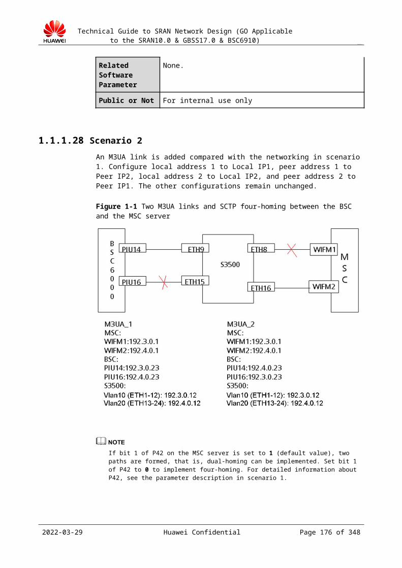
Technical Guide to SRAN Network Design (GO Applicable to the SRAN10.0 & GBSS17.0 & BSC6910)
CONFIDENTIAL
hops of the BSC. Heartbeat messages are transmitted over the trunk between CE1 and CE2.When ports are added to the internal interface boards of the BSC in this networking mode, new IP addresses must be added. New IP addresses and VRRPs must be also configured on peer devices.Logical IP addresses of each pair of active/standby interface boards of the BSC form an IP pool.The BTS is connected to the Ethernet network through a single Ethernet port.The BSC uses layer-3 networking.
Figure 19-1 Typical A over IP networking mode (pool of active/standby boards+manual active/standby LAGs+single IP address)
Layer-2 ports connecting CE1 and the BSC and connecting CE2 and the BSC are configured to the Access mode, and the BSC does not require VLAN tags.For standalone NEs, O&M data and service data is separated on the interface and a logical IP address must be configured for O&M data. Non-standalone NEs do not have this requirement.Route configuration examples
Device
Destination IP
Next Hop
Priority
BSC IP151 IP19 Default
BTS IP200 IP119 Default
CE1 IP200 IP11 Default
CE2 IP200 IP11 Default
Transmission fault detection schemeIP pool fault detection and switchover triggering mechanism: The IP pool on the BSC side starts the UDP ping detection.The active ports of the active/standby interface boards on the BSC enable two BFD sessions to detect the physical IP addresses of the two routers. The standby ports of active/standby interface boards on the BSC enable an ARP detection session. The BSC
2023-04-22 Huawei Confidential Page 176 of 258
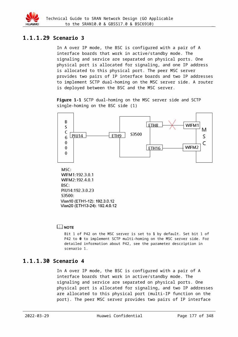
Technical Guide to SRAN Network Design (GO Applicable to the SRAN10.0 & GBSS17.0 & BSC6910)
CONFIDENTIAL
performs a BFD detection every 100 ms for three times and performs an ARP detection every 10s for three times. Configure the delay enabling BFD on CE1 and CE2 to avoid service interruption of CE1 and CE2 due to a reset upon power-off.Analysis of the fault switchover mechanism (only on single-fault scenarios)− CE1 is faulty (suspended or powered off): Heartbeat detection on the VRRP port of
CE2 fails and the standby VRRP port of CE2 becomes active. If the BSC sends packets to the BTS through CE1, the two BFD detections detect faults, manual active/standby LAGs switch over, and the BSC sends packets to the BTS through CE2. If the BSC sends packets to the BTS through CE2, only one BFD session on the BSC fails and the active/standby ports are not switched over. After CE1 is faulty, the OSPF re-converges, and the BTS sends packets to the BSC through CE2. Regardless of whether the BSC sends packets to the BTS through CE1 or CE2, the BSC and the BTS exchange messages through CE2. In this case, services are not interrupted.
− Connection between the BSC and CE1 is faulty: Heartbeat communication on the VRRP ports is correct and the VRRP ports are not switched over. If the BSC sends packets to the BTS through CE2, only the standby port is faulty, the active/standby ports are not switched over, and the original path remains unchanged. If the BSC sends packets to the BTS through CE1, it then sends packets through CE2: The two BFD sessions on the active port of the BSC fail, the active/standby ports switch over, and the path of uplink packets of the BSC is BSC => CE2 => CE1 => BTS. When the active/standby ports switch over, the BSC sends free ARP to update the ARP entries on CE1 and CE2. The BTS sends packets to the BSC through CE2. In this case, packets are sent to the BSC through CE1 and CE2, and services are not interrupted.
− Connection between two routers is faulty: BFD detection of heartbeat messages on VRRP1 fails and the standby port on CE2 becomes active, then VRRP1 has two active ports. One BFD detection on the active port of the BSC succeeds and the other BFD detection fails, then the active/standby ports are not switched over. If the BTS sends packets to the BSC through CE1, the original path remains unchanged. If the BTS sends packets to the BSC through CE2, then the BTS sends packets to the BSC through CE2 and CE3: BSC <=> CE2 <=> CE3 <=> BTS. In this case, packet sending from the BTS to the BSC is not interrupted. If the BTS sends packets to the BSC through CE1, packet sending is not interrupted. If the BTS sends packets to the BSC through CE2, packet sending is interrupted. That is, there is 50% probability that packet sending from the BTS to the BSC may be interrupted (see the following Note).
− Connection between CE1 and the intermediate network is faulty: The OSPF re-converges, and services are not interrupted.
− Manual switchover of ports on the BSC: VRRP routes and intermediate network routes are not affected. When the active/standby ports switch over, the BSC sends free ARP to update the ARP entries on CE1 and CE2. The BTS sends packets to the BSC through CE2. In this case, services are not interrupted.
− Interface boards of the BSC are faulty: The active/standby boards switch over, and the active/standby ports switch over. In this case, services are not interrupted.
Optional schemeNetworking: Pool of active/standby boards+dual-active ports+single IP addressLogical IP addresses of each pair of active/standby interface boards of the BSC form an IP pool. The BSC is directly connected to the dual routers through two independent ports on the active/standby interface boards. Device IP addresses are configured on the logical active board. With the active/standby MGW features of the source IP enabled, the active/standby paths are bound to the outgoing ports of the active/standby boards to achieve active/standby routes of the active/standby boards. Besides, the outgoing port routes of the active/standby boards are
2023-04-22 Huawei Confidential Page 177 of 258

Technical Guide to SRAN Network Design (GO Applicable to the SRAN10.0 & GBSS17.0 & BSC6910)
CONFIDENTIAL
configured and active/standby routes are configured for routers, so that the ports of the active/standby boards can protect each other.When ports are added to the internal interface boards of the BSC in this networking mode, new IP addresses must be added. New IP addresses and VRRPs must be also configured on peer devices.
Figure 19-2 Typical A over IP networking mode (pool of active/standby boards+dual-active ports+single IP address)
Configure IP addresses in the same network segment for each sub-interface, which facilitates route combination and simplifies intermediate network route. To facilitate network expansion, service IP addresses of the BSC use logical IP addresses (device IP addresses).Route configuration examples
Device
Destination IP Next Hop Priority
BSC
IP151 IP10 High
IP151 IP20 Low
IP161 IP20 High
IP161 IP10 Low
BTS1 IP210 IP119 Default
BTS6 IP220 IP129 Default
CE1IP210 IP11 High
IP220 IP11 Low
CE2IP210 IP21 Low
IP220 IP21 High
Local service IP addresses and peer service IP addresses are grouped in two. With route priority configuration, IP addresses in the two groups have different priorities, thereby
2023-04-22 Huawei Confidential Page 178 of 258
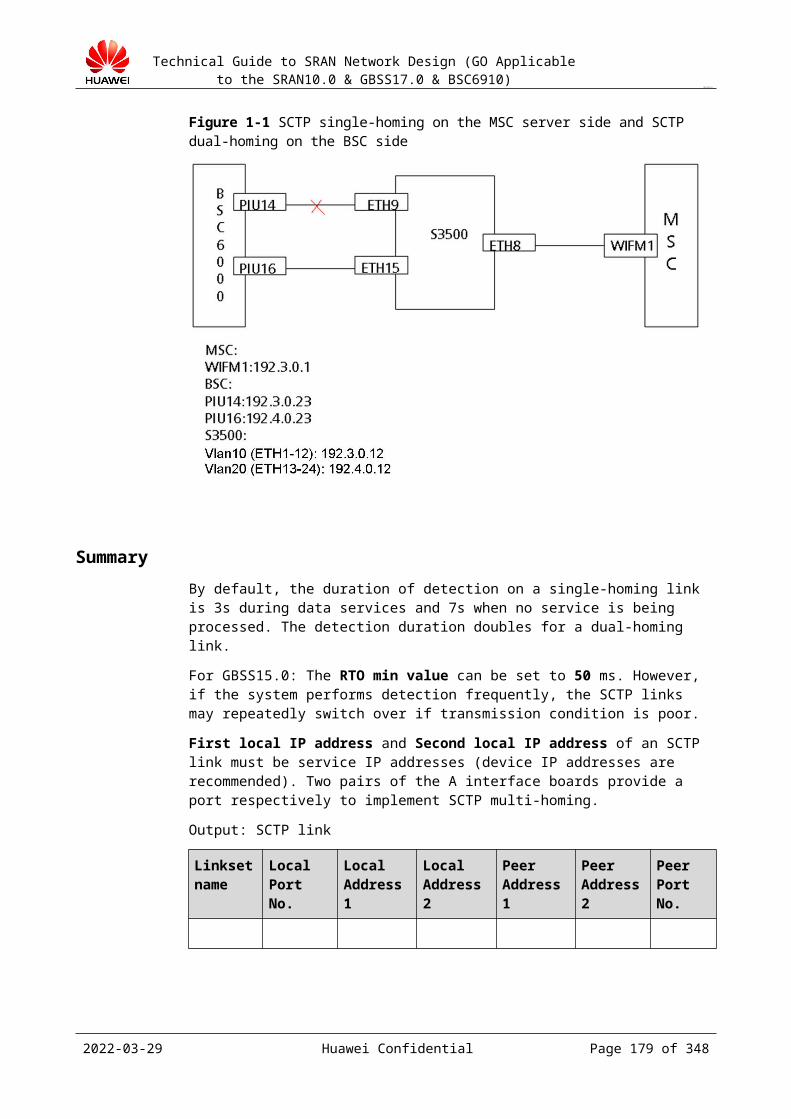
Technical Guide to SRAN Network Design (GO Applicable to the SRAN10.0 & GBSS17.0 & BSC6910)
CONFIDENTIAL
implementing load-sharing. In addition, backup routes are configured to ensure reliability.Dynamic route protocols (OSPF/ISIS) need to be configured between CE1 or CE2 and intermediate bearer networks. Static routes also need to be configured. In addition, route priorities need to be configured to ensure that the route between CE1 and IP150 has higher priority than the route between CE2 and IP150, and the route between CE2 and IP170 has higher priority than the route between CE1 and IP170. In this case, data is sent to CE1 through IP150 and sent to CE2 through IP170.Detection mechanismIP pool fault detection and switchover triggering mechanism: The IP pool on the BSC side starts the UDP ping detection.The active port of each board enables two BFD sessions to detect the IP addresses of the two routers. The BSC performs a BFD detection every 100 ms for three times. Configure the delay enabling BFD on CE1 and CE2 to avoid service interruption of CE1 and CE2 due to a reset upon power-off. If BFD is deployed between interface boards and the peer routers, the BSC triggers a switchover of the active/standby gateways in the source IP address routing table. The BSC can detect board faults and if it detects a board fault, the active/standby boards of the BSC switch over, and the logical IP address is migrated to a normal board from the faulty board. Accordingly, the source IP address route mapping the logical IP address is switched between the active/standby gateways.Analysis of the fault switchover mechanism (only on single-fault scenarios)Data transmission path in normal cases for BTS1: BSC -> CE1 -> CE3 -> BTS1; Data transmission path in normal cases for BTS6: BSC -> CE2 -> CE4 -> BTS6.− Connection between the BSC and CE1 is faulty: SBFD detection on the route from
the BSC to IP10 of CE1 fails and the active route whose next hop is IP10 becomes invalid. Then the active/standby routes switch over. The standby route whose next hop is IP20 becomes valid and services migrated to this route. At the same time, the static route that bound to the SBFD on CE1 becomes invalid, and the OSPF re-converges. The next hop of the route between CE3 and IP210 switches to CE2 from CE1 and the BTS sends packets to the BSC only through CE2. In this case, services are not interrupted.
− Connection between two routers is faulty: Services are not affected because no data is transmitted between CE1 and CE2 in normal cases.
− Connection between CE1 and CE3 is faulty: The OSPF re-converges. The next hop of the route between CE3 and IP210 switches to CE2 and the next hop of the route between CE1 and IP111 switches to CE3 from CE2. That is, the BSC sends packets to the BTS through this path: BSC -> CE1 -> CE2 -> CE3 -> BTS1. In this case, services are not interrupted.
− CE1 is faulty (suspended or powered off): SBFD detection on the route from the BSC to CE1 fails and the active route whose next hop is IP10 becomes invalid. Then the active/standby routes switch over. The standby route whose next hop is IP20 becomes valid and the BTS sends packets to the BSC through CE2. At the same time, the BFD for OSPF detection on CE3 indicates that CE1 is faulty, and the OSPF re-converges. The next hop of the route to IP210 switch to CE2 from CE1 and the BTS sends packets to the BSC through CE2. In this case, services are not interrupted.
Therefore, data sent to and received by one BTS is always through a certain port. The IP PM function can be used correctly.
Capacity restriction after the switchover is not taken into consideration.In this scheme, the assumed convergence time of the intermediate network is less than 1s.
2023-04-22 Huawei Confidential Page 179 of 258
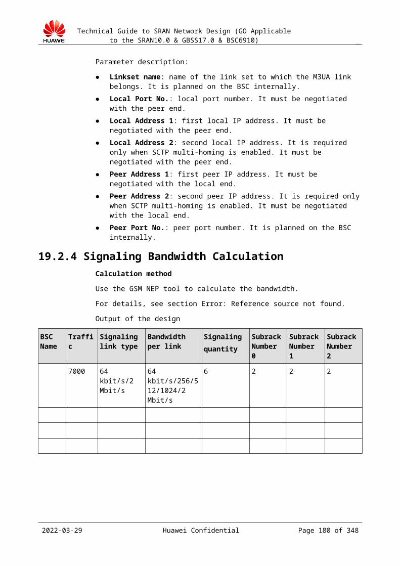
Technical Guide to SRAN Network Design (GO Applicable to the SRAN10.0 & GBSS17.0 & BSC6910)
CONFIDENTIAL
Active/standby scheme on the BTS side (do not use this scheme unless it is approved by the R&D department):
Basic principle:
In IP transmission mode, configure two FE/GE ports on the TMU of the BTS to work in active/standby mode. This scheme is specific to the customer who has high reliability requirements.
In the active/standby port mode, use the logical IP address for BTS communication. Configure two IP addresses for the Ethernet ports, and configure active and standby routes for the uplink outgoing interface of the BTS.
Configure the ARP sessions for the two next hops of the BTS, and set the session type to reliable session (enabling and disabling the related route based on the ARP session).
19.5.3 Bandwidth CalculationWhen designing Abis interface bandwidth, take certain redundancy into consideration for subsequent expansion. Determine the redundancy with the operator. Use a redundancy capacity of about 20%.
19.5.3.1 Abis over TDMFor the detailed bandwidth calculation formula, see section Error: Reference source not found.
The following description will help you understand timeslot allocation principles for the Abis interface.
The formula for calculating interface bandwidth is as follows:
Total BTS bandwidth = OML bandwidth + RSL bandwidth + TCH bandwidth + PDCH bandwidth + idle timeslot bandwidth
Timeslot multiplexing of the Abis interface belongs to statistical multiplexing. Multiple links share the 64 kbit/s bandwidth.
Basic principles are as follows:
A TCH occupies a 16 kbit/s timeslot. A PDCH occupies a 16 kbit/s timeslot. Each idle timeslot is 16 kbit/s. Signaling timeslots and service timeslots (TCH timeslot, PDCH timeslot, and idle
timeslot) are multiplexed on a 64 kbit/s timeslot.
2023-04-22 Huawei Confidential Page 180 of 258

Technical Guide to SRAN Network Design (GO Applicable to the SRAN10.0 & GBSS17.0 & BSC6910)
CONFIDENTIAL
Based on different multiplex ratios of the Abis interface, the bandwidth calculation formulas are as follows:
1:1 OML = 64 kbit/s RSL = 64 kbit/s 2:1 OML + RSL = 64 kbit/s 2 x RSL = 64 kbit/s Remaining RSL = 64 kbit/ 3:1 OML + 2 x RSL = 64 kbit/s 3 x RSL = 64 kbit/s Remaining RSLs (less than 3) =
64 kbit/s 4:1 OML + 3 x RSL = 64 kbit/s 4 x RSL = 64 kbit/s Remaining RSLs (less than 4) =
64 kbit/s 5:1 OML + 2 x RSL + ESL = 64 kbit/s 5 x RSL = 64 kbit/s Remaining RSLs (less
than 5) = 64 kbit/s (the Flex Abis function must be enabled.) 6:1 OML + 2 x RSL + ESL = 64 kbit/s 6 x RSL = 64 kbit/s Remaining RSLs (less
than 6) = 64 kbit/s (the Flex Abis function must be enabled.) 16 kbit/s mode: OML = 16 kbit/s RSL = 16 kbit/s
For the detailed timeslot distribution, see the BTS timeslot distribution on the LMT.
For a single site, use the GSM ENP to calculate Abis transmission timeslots.
19.5.3.2 Abis over IPFor the detailed bandwidth calculation formula, see section Error: Reference source not found.
Design of the Multiplex Ratio of Abis Signaling Links (TDM)
Aiming to improve the utilization rate of transmission resources over the Abis interface, statistical multiplexing is introduced to Abis RSLs. This technology allows signals over multiple RSLs to be multiplexed into one LAPD link for transmission. The ratio of the number of multiplexed RSLs to the number of actually occupied LAPD links is called the multiplex ratio. For example, if signals over N RSLs are transmitted over one LAPD link, the multiplex ratio is N:1. The multiplex ratio is configured as a parameter for the BTS. The ratio of the multiplex ratio to the multiplex ratio related to the BTS is called the BTS multiplex ratio.
2023-04-22 Huawei Confidential Page 181 of 258
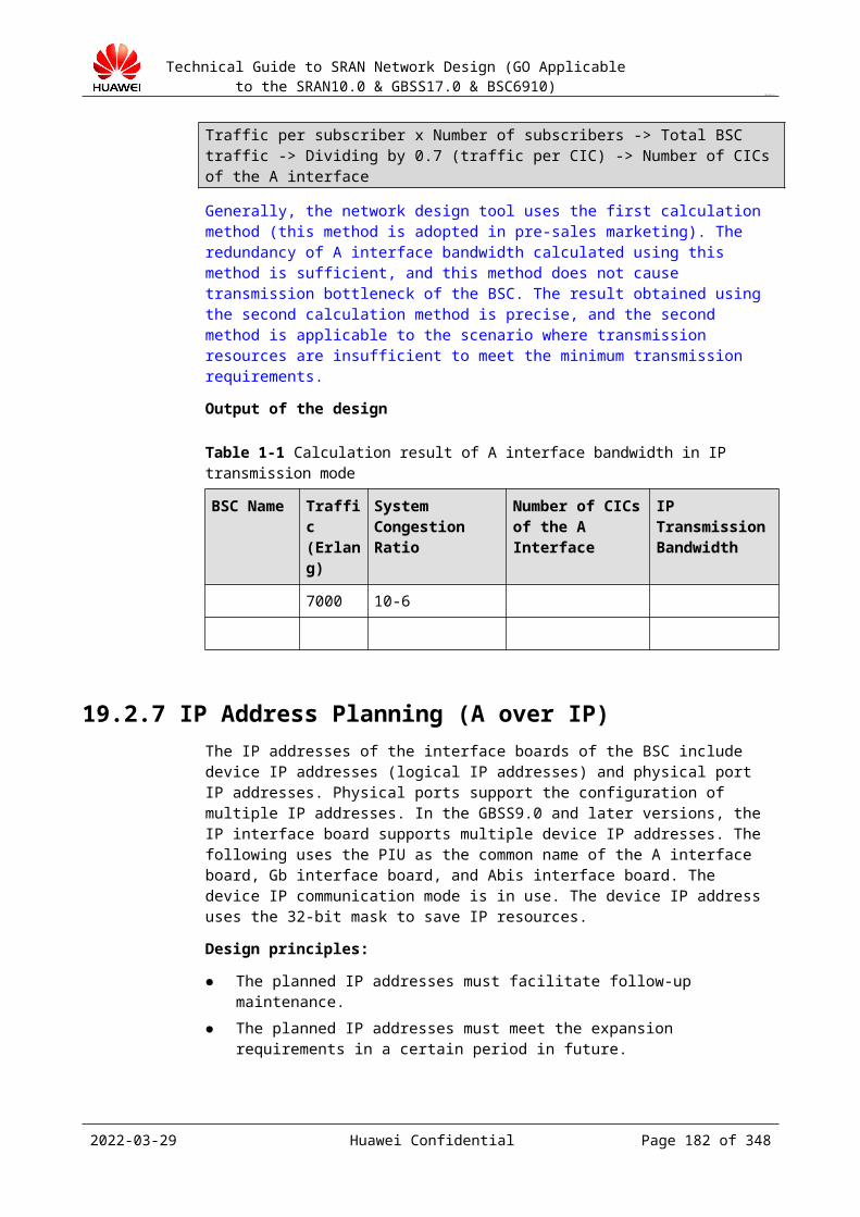
Technical Guide to SRAN Network Design (GO Applicable to the SRAN10.0 & GBSS17.0 & BSC6910)
CONFIDENTIAL
The multiplex ratio of Abis signaling links determines the bandwidth of each Abis signaling link. A proper multiplex ratio for a network helps improve the utilization rate of transmission bandwidth. The recommended BTS multiplex ratio used in common situations is as follows:
If the half-rate transmission is disabled, the recommended ratio is 4:1 or 2:1. If the half-rate transmission is enabled, the recommended ratio is 2:1 or 1:1.
To calculate the multiplex ratio, use the following formula:
BTS multiplex ratio = 64 x 1024 x Payload rate of LAPD links/8/RSL bandwidth
Round off the calculation result of the preceding formula to the nearest integer. The result is the BTS multiplex ratio. For example, if the calculation result value obtained is 2.6, the BTS multiplex ratio is 2:1. Note that when 16 kbit/s signaling links are used on the Abis interface, multiplexing is not applicable, and the multiplex ratio is fixedly 1.
The following describes the fields in the preceding formula:
The number 64 indicates that the bandwidth of each LAPD link is 64 kbit/s. The number 1024 indicates that 1024 bits equal to one k. The number 8 indicates that eight bits equal to one byte. The payload rate of LAPD links ranges from 70% to 75%. The RSL bandwidth is calculated as follows: RSL bandwidth = Average number of peak-
hour messages for a TRX/3600.− Average number of peak-hour messages for a TRX = [a x (Number of bytes in peak-
hour call-related messages + Number of bytes in handover-related messages + Number of peak-hour messages for call measurement reports) + b x Number of bytes in peak-hour messages for location updates + c x Number of bytes in received and sent peak-hour messages + d x Average number of bytes in peak-hour pagings] x Number of subscribers supported by each TRX
− Number of bytes in peak-hour call-related messages = Number of originating peak-hour calls x Average number of bytes in messages for an originating call + Number of received peak-hour calls x Average number of bytes in messages for a received call
− Number of bytes in handover-related messages = Number of intra-BSC handovers x Average number of bytes in messages for an intra-BSC handover + Number of inter-BSC handovers x Average number of bytes in messages for an inter-BSC handover
− Number of peak-hour messages for call measurement reports = (Number of originating peak-hour calls + Number of received peak-hour calls) x Average number of measurement reports for a call x Average number of bytes in a measurement report
− Number of bytes in peak-hour messages for location updates = Number of peak-hour location updates x Average number of bytes in messages for a location update
− Number of bytes in received and sent peak-hour messages = Number of sent peak-hour short messages x Average number of bytes in messages for a mobile originating short message + Number of received peak-hour short messages x Average number of bytes in messages for a mobile terminating short message
− Average number of bytes in peak-hour pagings = Number of received peak-hour calls + Number of received peak-hour short messages + Average number of re-pagings) x Average number of bytes in messages for a paging
− Number of subscribers supported by each TRX = Traffic volume of the site/Peak-hour traffic volume for each subscriber/Number of TRXs for a site
− Average number of measurement reports for a call = Average duration of a call/0.5
2023-04-22 Huawei Confidential Page 182 of 258
Technical Guide to SRAN Network Design (GO Applicable to the SRAN10.0 & GBSS17.0 & BSC6910)
CONFIDENTIAL
− Average number of re-pagings = (Number of received peak-hour calls + Number of received peak-hour short messages) x Average ratio of re-pagings to total pagings. The value of the average ratio of re-pagings to total pagings ranges from 0.2 to 0.4 and the most used value is 0.35.
Table 19-1 describes the performance test results of parameters a, b, c, and d.
Table 19-1 Performance test results of parameters a, b, c, and d
Service a: Call (No Paging) b: Location Update c: Short Message (No Paging) d: Paging
Weight 100% 60% 80% 1%
Table 19-2 lists estimates of data related to parameters a, b, c, and d.
Table 19-2 Estimates of data related to parameters a, b, c, and d
Parameter Value
Average number of bytes in messages for an originating call 230
Average number of bytes in messages for a received call 240
Average number of bytes in messages for an intra-BSC handover 80
Average number of bytes in messages for an inter-BSC handover 80
Average number of bytes in a measurement report 60
Average number of bytes in messages for a location update 90
Average number of bytes in messages for a mobile originating short message 220
Average number of bytes in messages for a mobile terminating short message 220
Average number of bytes in messages for a paging 16
19.5.4 IP Address PlanningThe interface board of the BSC is configured with the device IP address (also called logical IP address) and port IP address. Multiple port IP addresses can be configured. The packet interface unit (PIU) is the common name of the A-interface board, Gb interface board, and Abis interface board.
Design principles:
IP addresses can facilitate future maintenance. The planned IP addresses can meet future expansion requirements. The planned IP addresses are added with different VLAN tags based on different
destination IP addresses for easy maintenance and expansion.
Design guide:
2023-04-22 Huawei Confidential Page 183 of 258
Technical Guide to SRAN Network Design (GO Applicable to the SRAN10.0 & GBSS17.0 & BSC6910)
CONFIDENTIAL
Step 1 Select a communication mode (port IP communication or device IP communication). For the best results, adopt device IP communication for the Abis interface board on the BSC side (if a device IP address is configured) and port IP communication for the interface board (TMU board) on the BTS side.
Configure and use the port IP address or device IP address. The system automatically identifies the communication mode (port IP communication or device IP communication). The processing of the A interface and Gb interface is the same as the processing of the Abis interface.
Step 2 Allocate device IP addresses according to the networking design scheme for the Abis interface and the calculated number of FE/GE ports of the Abis interface on the BSC side in the bandwidth design.
Step 3 Allocate port IP addresses. In active/standby boards+manual active/standby LAGs, configure a group IP address (IP address of the active port) for the trunk. In addition, configure an IP address for the standby port during ARP detection. The IP address of the active port must be in the same network segment as that of the standby port.
Step 4 If the layer-3 networking and device IP communication are adopted, configure a route to the device IP address of the BSC for the intermediate router. If the layer-3 networking and port IP communication are adopted, do not configure a route to the port IP address of the BSC for the intermediate device.
Step 5 If the BSC is required to add VLAN tags according to the next hop or service type in the E2E solution, configure the function of adding VLAN tags according to the next hop or service type on the BSC side.
----End
Principles of IP address planning
The device IP address is a logical IP address that a board uses for communication. The device IP address is valid for all the port IP addresses of the board. Use the active/standby board networking mode. Use the device IP communication mode for the Abis interface board on the BSC side, and the port IP communication mode for the Abis interface board on the BTS side.
When the FE interface is used, one board can be configured with eight port IP addresses that are in different network segments. When the GE interface is used, one board can be configured with two port IP addresses. Port IP addresses must be in different network segments from device IP addresses. When the PIU works in active/standby mode, the port IP addresses of the active and standby PIUs must be in the same network segment.
One physical port can be configured with a maximum of six IP addresses that must be in different network segments.
If the physical address of the PIU on the BSC side is in the same network segment as that of the PTU/GTMU on the BTS side, layer-2 interworking is allowed.
If the physical address of the PIU on the BSC side is in a different network segment from that of the PTU/GTMU on the BTS side, layer-2 interworking is not supported, and a layer-3 device (for example, layer-3 switch or router) is required for routing. This is called layer-3 networking.
The gateway IP address must be in the same network segment as the port IP address of the board.
The IP address cannot be all 0s or all 255s. The IP address cannot be a loopback address whose network number is 127.x.x.x.
2023-04-22 Huawei Confidential Page 184 of 258
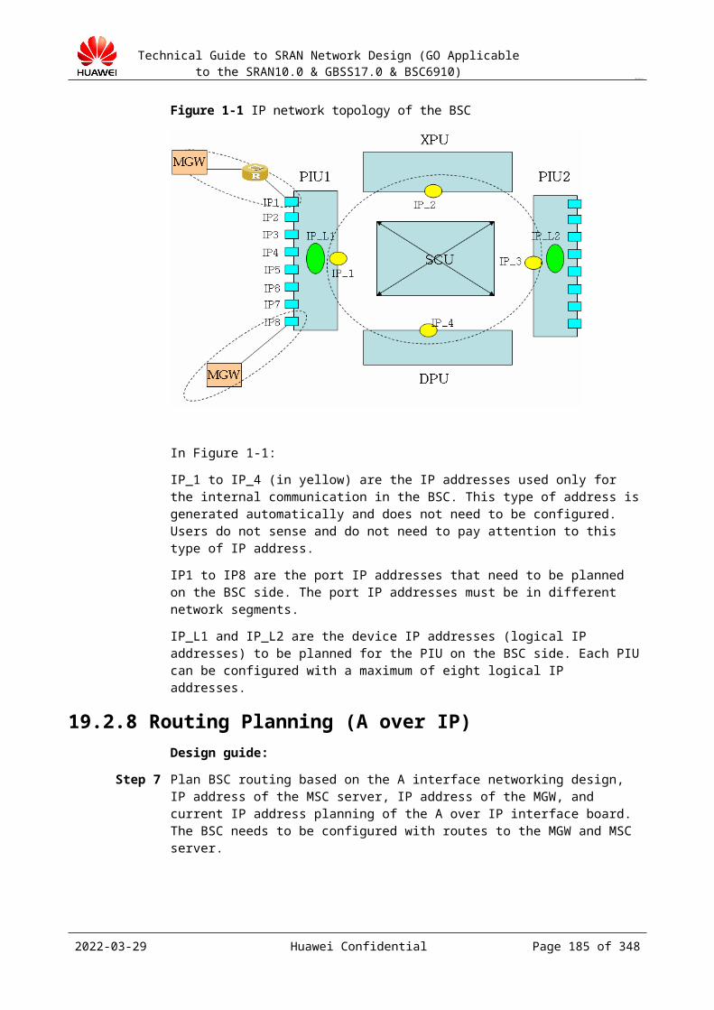
Technical Guide to SRAN Network Design (GO Applicable to the SRAN10.0 & GBSS17.0 & BSC6910)
CONFIDENTIAL
The IP address cannot be the multicast IP address of category D, that is, address in the range of 224.0.0.0 to 239.255.255.255.
The IP address cannot be the reserved IP address of category E, that is, address in the range of 240.0.0.0 to 247.255.255.255.
Output: IP address planning in Abis over IP mode
BSC Attribute (for Abis over IP communication method)
Abis IP Type
Parameter description:
Abis IP Type: communication mode (logical IP communication or port IP communication) that the Abis interface adopts in Abis over IP mode.
Device IP (logical IP) of BSC side board
Subrack No.
Slot No.
Sub System No.
Device IP Address
Subnet Mask
Ethernet port IP of BSC side board
Subrack No.
Slot No.
Port No.
IP Address Index
Port IP Address
Port Standby IP Address
Subnet Mask
IP VLAN
Subrack No. Slot No. Dest IP Address VLAN ID
Parameter description:
Dest IP Address: next hop IP address of the destination BTS. VLAN ID: VLAN ID of the next hop of the BSC port corresponding to the destination
IP address, that is, VLAN ID carried in the IP packet.
BTS Information
2023-04-22 Huawei Confidential Page 185 of 258

Technical Guide to SRAN Network Design (GO Applicable to the SRAN10.0 & GBSS17.0 & BSC6910)
CONFIDENTIAL
Site Index
Site Name
Site Type
Upper-level Port No
Service Mode
Site IP Address
Site IP SubnetMask
Auto Negotiation Mode
Port Rate(M)
Duplex Mode
MTU BTS Bar Code
Reference Clock Source type
IP Clock Port
Subrack No.(BSC)
Slot No. (BSC)
Port No. (BSC)
BSC IP BSC IP Mask
Activity State
Longitude
Latitude
Parameter description:
Site Index: index number of a site. This parameter uniquely identifies a site in a BSC. Site Name: name of a site. Site Type: BTS type of a site. Upper-level Port No: upper-level port number. In Abis over IP mode, only the star
networking is supported, and therefore this parameter is set to the outgoing port number of the directly connected BSC.
Service Mode: service type. In Abis over IP mode, this parameter is set to IP. Site IP Address: IP address allocated to a site. Site IP Subnet Mask: subnet mask allocated to a site. Auto Negotiation Mode, Port Rate(M), Duplex Mode, and MTU: must be negotiated
with the device directly connected to the IP interface board of the BTS. BTS Bar Code: electronic label of the BTS. This parameter must be correctly set;
otherwise, the BTS cannot be started. Reference Clock Source type: type of the reference clock source of the BTS. Values are
IP Time, Trace Transport Clock, Transport Clock, Internal Clock, External sync. Clock, and Trace GPS Clock. Set this parameter to IP Time if the IP clock server is used to provide clocks and Trace GPS Clock if the GPS is used to provide clocks.
IP Clock Port: indicates that the BTS uses the IP clock server as the clock source. When the BTS functions as the client, this parameter is constantly set to 33003 and cannot be modified.
Subrack No.(BSC): subrack number of the interface board of the BSC connected to the BTS.
Slot No.(BSC): slot number of the interface board of the BSC connected to the BTS.
2023-04-22 Huawei Confidential Page 186 of 258

Technical Guide to SRAN Network Design (GO Applicable to the SRAN10.0 & GBSS17.0 & BSC6910)
CONFIDENTIAL
Port No.(BSC): port number of the interface board of the BSC connected to the BTS. BSC IP: port IP addresses (destination IP address) of the interface board of the BSC
connected to the BTS.
19.5.5 Routing PlanningIn Abis over IP mode, only static routes are supported. All routes need to be configured manually.
Design principles:
The designed routing solution must facilitate follow-up maintenance. The route to the BTS needs to be configured on the BSC. When the BTS adopts the device IP address for communication, a route to the BTS needs
to be configured on the BSC. When the BTS adopts the port IP address for communication and the layer-2 networking
is available, no route to the BTS needs to be configured on the BSC. When the BTS adopts the port IP address for communication and the layer-3 networking
is available, a route to the BTS needs to be configured on the BSC. The route to the BSC cannot be configured on the BTS. The BTS calculates the route to
the BSC according to the information delivered by the BSC.
Design guide:
Step 1 Plan routes for the BSC according to the networking design scheme for the Abis interface and the reliability design.
Step 2 If the layer-3 networking is adopted and the BSC uses the device IP address for communication, configure the route to the device IP address of the BSC on the intermediate router.
Step 3 If the layer-3 networking is adopted and the BTS uses the device IP address for communication, configure the route to the device IP address of the BTS on the intermediate router.
----End
Principles of routing planning:
When the BTS adopts port IP addresses to provide services, the BTS does not support load sharing. Instead, only one FE port IP address can be configured, and the port IP address is the same as the logical IP address. In layer-2 networking, no route to the BTS needs to be configured on the BSC because the physical address of the FE port of the PIU (IP interface board on the BSC side) is in the same network segment as that of the FE port of the PTU (IP interface board on the BTS side).
When the BTS is configured with logical IP addresses for providing services, the BTS can be configured with two FE port IP addresses for load sharing. In this case, configure two FE port IP addresses (they must be in different network segments), one logical IP address (that is, the IP address of the BTS), and a route from the BSC to the logical IP address of the BTS, with the next hop being the physical IP address and the destination address being the logical address of the PTU.
Set Destination IP to a network address in the network segment of the IP address of the BTS.During communication, a network address is used to address the peer device. The network address is obtained by performing the AND operation on the peer IP address and
2023-04-22 Huawei Confidential Page 187 of 258
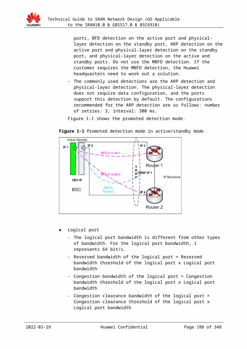
Technical Guide to SRAN Network Design (GO Applicable to the SRAN10.0 & GBSS17.0 & BSC6910)
CONFIDENTIAL
the subnet mask. For example, if the peer IP address is 192.168.80.2 and the subnet mask is 255.255.255.128, the network address is 192.168.80.0.
Set Subnet Mask to the subnet mask of the destination device. Set Gateway Address to an address that is in the same network segment as the IP
address of the related port of the interface board on the BSC side. The DHCP relay is configured on the router connected to the BTS, and no configuration
is required on the BSC port.
Output: Abis over IP routing design
Subrack No.
Slot No. Destination IP Address
Subnet Mask
Gateway Route Priority
Parameter description:
Destination IP Address: network IP address of the destination IP address of the peer BTS (destination of the data from the Abis interface board of the BSC). If the peer BTS does not have a device IP address (logical IP address), this parameter indicates the network IP address of the port IP address. The network IP address is obtained by performing the AND operation on the device IP address (or port IP address if no device IP address is available) of the BTS and the subnet mask.
Subnet Mask: subnet mask of the IP address of the BTS of the peer device. Gateway: port IP address of the device directly connected to the outgoing port of the Gb
interface board on the BSC. The IP address specified by this parameter must be in the same network segment as the IP address of the outgoing port of the Gb interface board on the BSC.
Route Priority: route priority. The default value is 1.
19.5.6 QoS DesignDesign principles:
Port link detection
The BFD detection of the interface and ARP link detection cannot be enabled at the same time.
One port can be configured with only one detection mode. When a port is configured with neither BFD detection nor ARP link detection, physical layer detection is adopted.
The following detection modes are supported: BFD detection for the active port, ARP link detection for both active and standby ports, BFD detection for the active port and physical layer detection for the standby mode, ARP link detection for the active port and physical layer detection for the standby mode, and physical layer detection for both active and standby ports.
ARP link detection and physical layer detection are mainly used. Physical layer detection does not need to be configured and is supported by all ports by default. Configure the retry attempts for ARP link detection to 3 with 300 ms per attempt.
Design guide:
Step 1 Design the port QoS attribute parameters based on the capability of the interworking device.
2023-04-22 Huawei Confidential Page 188 of 258
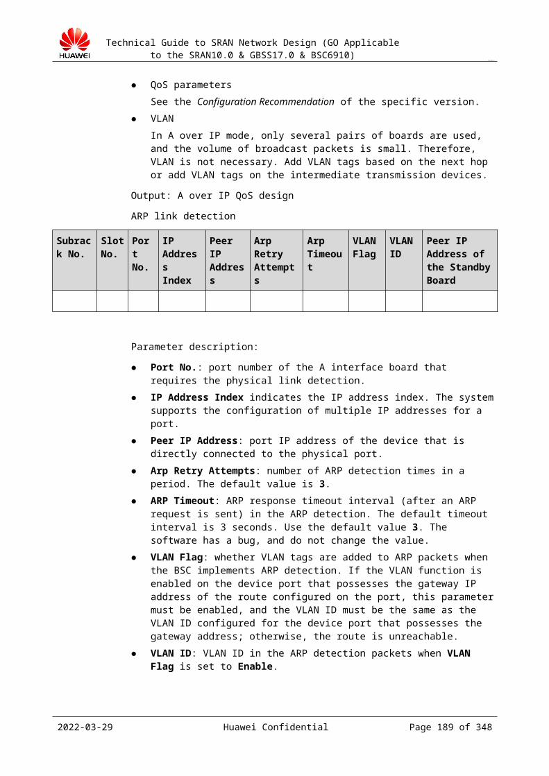
Technical Guide to SRAN Network Design (GO Applicable to the SRAN10.0 & GBSS17.0 & BSC6910)
CONFIDENTIAL
Step 2 Determine the port link detection mode (BFD detection, ARP link detection, or physical layer detection) according to the support capabilities of the interconnected device.
Step 3 Design IP addresses and VLANs.
Step 4 Design VLAN priorities and DSCP mappings.
Huawei GBSS provides the same QoS assurance mechanism for Abis over IP transmission and A over IP transmission to provide E2E QoS assurance, including the physical layer, link layer, IP layer, and application layer.
----End
Output: Abis over IP QoS design
ARP link detection
Subrack No.
Slot No.
Port No.
IP Address Index
Peer IP Address
Arp Retry Attempts
Arp Timeout
VLAN Flag
VLAN ID
Peer IP Address of the Standby Board
Parameter description:
Port No.: port number of the Abis interface board that requires the physical link detection.
IP Address Index: index of an IP address. The system supports the configuration of multiple IP addresses for a port.
Peer IP Address: port IP address of the device that is directly connected to the physical port.
Arp Retry Attempts: number of ARP detection times in a period. The default value is 3. ARP Timeout: ARP response timeout interval (after an ARP request is sent) in the ARP
detection. The default timeout interval is 3 seconds. Use the default value 3. The software has a bug, and do not change the value.
VLAN Flag: whether VLAN tags are added to ARP packets when the BSC implements ARP detection. If the VLAN function is enabled on the device port that possesses the gateway IP address of the route configured on the port, this parameter must be enabled, and the VLAN ID must be the same as the VLAN ID configured for the device port that possesses the gateway address; otherwise, the route is unreachable.
VLAN ID: VLAN ID in the ARP detection packets when VLAN Flag is set to Enable. Peer IP Address of the Standby Board: physical IP address of the peer port directly
connected to the physical port of the standby board.
BFD detection
2023-04-22 Huawei Confidential Page 189 of 258

Technical Guide to SRAN Network Design (GO Applicable to the SRAN10.0 & GBSS17.0 & BSC6910)
CONFIDENTIAL
Subrack No.
Slot No.
Port No.
IP Address Index
Peer IP Address
MinTxInterval(ms)
MinRxInterval(ms)
Detect Mult
Peer IP Address of the Standby Board
Parameter description:
Peer IP Address: peer IP address in the BFD session. The BFD detection supports only the next hop detection. Therefore, the peer IP address in the BFD session is the port IP address of the device that is directly connected to the port.
MinTxInterval(ms): minimum interval between the BFD control packets that the local system sends.
MinRxInterval(ms): minimum interval between the BFD control packets that the local system receives.
Detect Mult: number of detection times, that is, the link is considered disconnected after the detection fails for the specified number of times.
For details about the other parameters, see the parameter description in "ARP link detection."
Logic Port
Subrack No.
Slot No.
Physical Port No.
Logic Port No.
Bandwidth of the Logical Port(32Kpbs)
Reserved Bandwidth Threshold(%)
Congestion Bandwidth Threshold(%)
Congestion Clear Bandwidth Threshold(%)
Parameter description:
Physical Port No.: physical port number of the interface board to which the logical port belongs.
Bandwidth of the Logical Port(32Kpbs): fixed bandwidth of the logical port. It ranges from 32 kbit/s to 64 kbit/s. The sum of the bandwidths of all the logical ports bound to the same physical port cannot exceed the bandwidth of the physical port.
Reserved Bandwidth Threshold(%): reserved threshold of the logical port, that is, the percentage of the logical port reserved bandwidth to the logical port bandwidth. The default value is 95.
Congestion Bandwidth Threshold(%): congestion threshold of the logical port, that is, the percentage of the logical port congestion bandwidth to the logical port bandwidth. The default value is 85.
Congestion Clear Bandwidth Threshold(%): congestion clearance threshold of the logical port, that is, the percentage of the congestion clearance bandwidth to the logical port bandwidth. The default value is 75.
BSC ABIS MUX
2023-04-22 Huawei Confidential Page 190 of 258

Technical Guide to SRAN Network Design (GO Applicable to the SRAN10.0 & GBSS17.0 & BSC6910)
CONFIDENTIAL
ABIS MUX State
Subrack No.
Slot No.
Site ID
Service Type
Multiplexing SubFrame Threshold
Multiplexing Packet Length Threshold
Time Out(0.1ms)
Parameter description:
ABIS MUX State: whether to enable the Abis MUX function. Site ID: ID of a site, which is unique in a BSC. Service Type: service type of the Abis MUX function on the IP-based interface board.
Service types are as follows: OML service, RSL service, EML service, ESL service, CS voice service, CS data service, PS service (high priority), and PS service (low priority).
Multiplexing SubFrame Threshold: multiplexing subframe threshold. If the data streams on the same MUX channel are multiplexed, their multiplexing types must be the same and the packet length before the multiplexing cannot exceed the multiplexing subframe threshold.
Multiplexing Packet Length Threshold: threshold for the length of the multiplexed packet. The packet length after the multiplexing cannot exceed this parameter value. If the packet length after the multiplexing exceeds this parameter value, the packet is directly sent and no subracks are added. This parameter value refers to the payload, excluding the IP/UDP header.
Time Out(0.1ms): maximum multiplexing waiting time. When no content is added to the multiplexed packet within the time specified by this parameter, the timer expires and the packet is directly sent. The duration of the timer depends on the average number of packets to be multiplexed within the timer. The more the number of packets to be multiplexed, the longer the duration of the timer.
BSC ABIS MUX is optional. Set it when the Abis MUX technology is adopted to improve the IP transmission efficiency of the Abis interface. The Abis MUX function is available when only the GFGUB board is configured with the BTS supporting IP transmission, the PTU of the BTS is configured with the BTS Abis MUX function, and the GFGUB board is configured with the BSC Abis MUX function. The Abis MUX function is valid only when the Abis MUX function is enabled on the BSC and BTS sides at the same time. The parameters for the BTS Abis MUX function are the same as those for the BSC Abis MUX function.
19.5.7 Abis Port Allocation Design Subrack-based Abis port planning by LAC
To minimize the inter-subrack signaling traffic caused due to inter-cell handover and paging forwarding, plan the BTSs in the same LAC to the same BM subrack as possible as you can.
Discontinuous BTS distribution in a subrack (optional)The BTSs in a subrack can be distributed between boards in a discontinuous manner. Overlapping coverage exists between adjacent cells. Based on discontinuous BTS distribution, adjacent BTSs are distributed to different Abis interface boards. When a board is faulty, the BTS under it is out of service but the overlapping coverage of the peripheral cells can still ensure services to a certain degree. This can minimize the impacts of board faults.
2023-04-22 Huawei Confidential Page 191 of 258
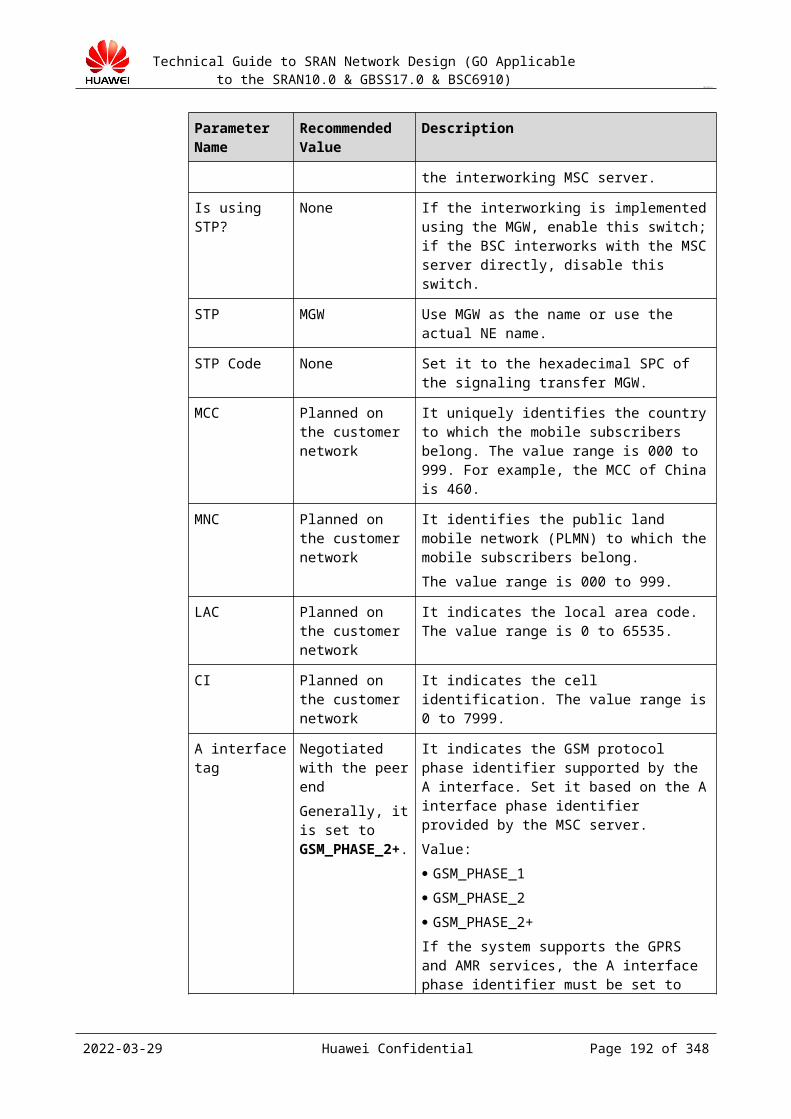
Technical Guide to SRAN Network Design (GO Applicable to the SRAN10.0 & GBSS17.0 & BSC6910)
CONFIDENTIAL
The BTS must be evenly distributed to different interface boards based on the station module to ensure load balance among boards.
Continuous BTS distribution in a subrackBTSs are continuously distributed in a BM subrack according to the longitude and latitude. Select this principle or the principle of discontinuous BTS distribution in a subrack according to the actual situation.The BTS must be evenly distributed to different interface boards based on the station module to ensure load balance among boards.
Batch site establishmentFor certain projects, sites need to be established in batches due to transmission providing capabilities, engineering implementation capabilities and customer requirements. Based on special requirements, the site distribution strategy can be adjusted. For the best results, abide by the principle of subrack-based Abis port planning by LAC.
19.6 Abis Interface Design (IP over E1)
19.6.1 Interface Description
The interface description is the same as that in section 19.5.1 "Interface Description."
Only the POUc board (IP over STM-1) of the BSC6910 supports IP over E1 over the A interface.
19.6.2 Networking Design
The IP over E1 networking over the Abis interface can be classified into two types: non-cascading IP over E1 networking and cascading IP over E1 networking.
Non-Cascading IP over E1 NetworkingIn the non-cascading IP over E1 networking mode, the BTS directly uses the IP over E1 transmission to communicate with the BSC. This networking includes the following scenarios:
Direct connection between the BTS and BSC using IP over E1 (the BTS is considered directly connected to the BSC although an SDH network is deployed between the BTS and BSC)
2023-04-22 Huawei Confidential Page 192 of 258

Technical Guide to SRAN Network Design (GO Applicable to the SRAN10.0 & GBSS17.0 & BSC6910)
CONFIDENTIAL
Figure 19-1 Direction connection between the BTS and BSC using IP over E1
Channelized STM-1 ports are the only available physical ports on the BSC side.
Cascading IP over E1 NetworkingIn the cascading IP over E1 networking mode, BTSs in IP over E1 mode may be cascaded with those in TDM mode. This networking includes the following scenarios:
Chain networking when all the BTSs use IP over E1 transmission
Figure 19-2 Chain networking when all the BTSs use IP over E1 transmission
PPP links are terminated between two BTSs. The intermediate BTSs work as the routes for forwarding the traffic of lower-level BTSs to the BSC, and the routes to destination IP addresses of all BTSs must be configured on the BSC.
Tree networking when all the BTSs use IP over E1 transmission
2023-04-22 Huawei Confidential Page 193 of 258

Technical Guide to SRAN Network Design (GO Applicable to the SRAN10.0 & GBSS17.0 & BSC6910)
CONFIDENTIAL
Figure 19-3 Tree networking when all the BTSs use IP over E1 transmission
PPP links are terminated between two BTSs. The intermediate BTSs work as the routes for forwarding the traffic of lower-level BTSs to the BSC, and the routes to destination IP addresses of all BTSs must be configured on the BSC.
The BTSs that use IP over E1 over the Abis interface can be cascaded. In this situation, the upper-level BTSs must provide the DHCP relay function for lower-level BTSs so that device IP addresses (logical IP addresses) can be obtained using the DHCP and used for communication after PPP or MP negotiation is successful.
Among cascaded BTSs using IP over E1, the upper-level BTSs must work as the routes for forwarding packets of lower-level BTSs. Otherwise, when the BTSs are cascaded, leaf or intermediate BTSs cannot establish communications with the BSC.
19.6.3 Transmission Bandwidth Design
For details about how to calculate the transmission bandwidth, see 10.2.2 Abis Interface.
19.6.4 Configuration Principles
In IP over E1 mode, E1 links can be configured as PPP links or an MP. Generally, a single E1 link can be configured as a PPP link. Multiple E1 links can be configured as an MP. A single E1 link which may be expanded subsequently can be configured as an MP. This helps subsequent capacity expansion adjustment.
The Abis on the BSC6900 uses a resource pool and therefore IP paths are not required.
2023-04-22 Huawei Confidential Page 194 of 258
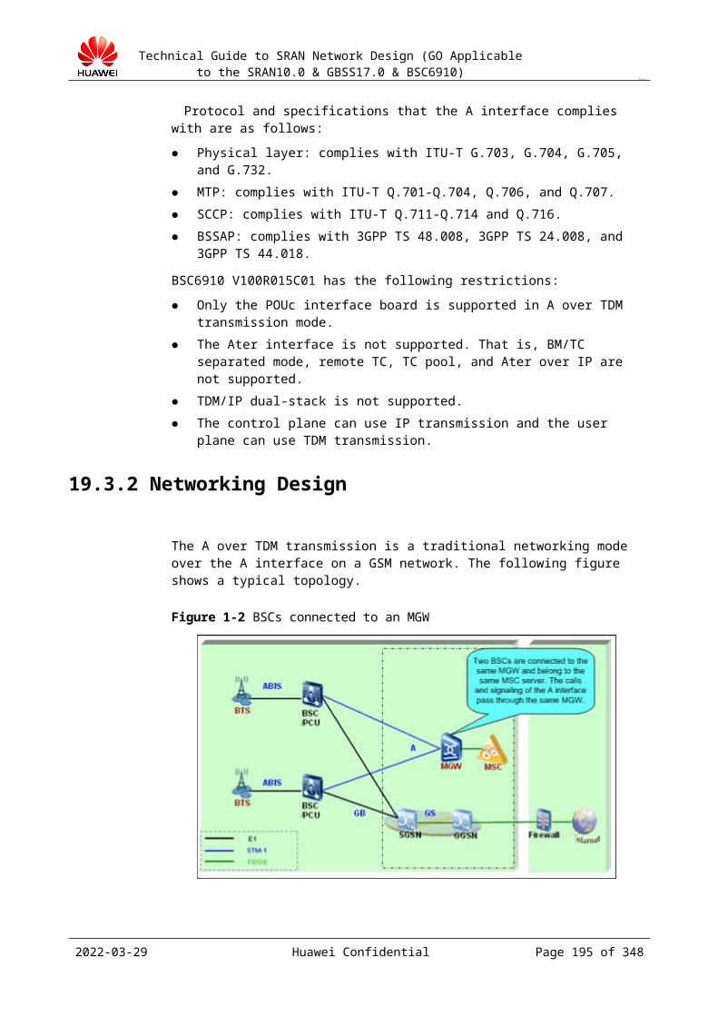
Technical Guide to SRAN Network Design (GO Applicable to the SRAN10.0 & GBSS17.0 & BSC6910)
CONFIDENTIAL
19.6.5 IP Planning
In IP over E1 transmission mode, both the BTS and BSC support the device IP (using the local device IP) and port IP addresses.
The device IP address is recommended on the BSC side (the MP or PPP links use the local device IP). This saves IP addresses. The port IP address is recommended on the BTS.
19.6.6 Route Planning
The BSC is directly connected to the BTS over the PPP/MP.
If the BTS IP address and the BSC IP address are included in the MP group. Routes are not required on both the uplink and downlink.
If the BTS uses a logical IP address for communication, the BSC must be configured with a route from the BTS to the logical IP address (the next-hop IP address is the PPP or MP IP address on the BTS side).
If the BSC IP address is the same as a specified DEVIP, the BTS must be configured with a route to the BSC DEVIP by running the ADD BTSIPRT command with Route Type set to OUTIF.
19.6.7 QoS Planning
For details, see Abis Interface Configuration Specification_IP(GBSS17.0) and A&GB Interface Configuration Specification_IP(GBSS17.0).
http://support.huawei.com/support/pages/kbcenter/view/product.do?actionFlag=detailProductSimple&web_doc_id=SC0000783702&doc_type=123-2&doc_type=123-2/support/pages/kbcenter/view/product.do?actionFlag=detailProductSimple&web_doc_id=SC0000783702&doc_type=123-2
19.6.8 Clock Synchronization
In IP over E1 transmission mode, the BTS can extract a line clock from E1 links, and the line clock is used as the clock reference source.
2023-04-22 Huawei Confidential Page 195 of 258
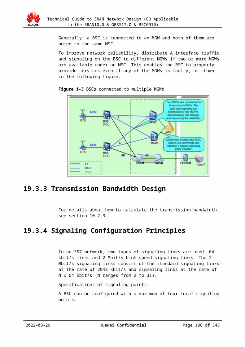
Technical Guide to SRAN Network Design (GO Applicable to the SRAN10.0 & GBSS17.0 & BSC6910)
CONFIDENTIAL
19.7 Lb Interface Design19.7.1 Interface Description
Lb is a standard interface between the BSC and the Serving Mobile Location Center (SMLC). The BSC provides the LCS for subscribers over the Lb interface by using the external SMLC.
LCSs can increase operators' revenues. Operators can provide various LCSs for subscribers based on subscribers' locations. LCSs include weather forecasts, trip scheduling, emergency assistance, stock information, business planning, and transportation information.
With the Lb Interface feature, Huawei GSM BSS equipment can be connected to the SMLC and LMU (TypeB) of other vendors to provide the LCS in CellID+TA, or AGPS mode. The Lb interface complies with the 3GPP TS 48.071, 3GPP TS 49.031, 3GPP TS 44.031, and 3GPP TS 03.71.
The SMLC selects a positioning mode, manages the positioning process, and estimates the location of an MS based on the measurement results reported by the MS.
Figure 19-1 shows the SMLC-based network topology for the Lb interface.
Figure 19-1 SMLC-based network topology for the Lb interface
Huawei's BSS supports message tracing over the Lb interface and can provide LCS performance measurement entities.
Huawei BSS supports flow control on LCS services. When the external SMLC is overloaded or the number of LCS requests received by the BSC exceeds the maximum limit, the BSC rejects some LCS requests to ensure the correct running of the GPS.
19.7.2 Function Interaction
The LCS service is mutually exclusive with the following functions:
GBFD-115401 NSS-Based LCS (Cell ID+TA) GBFD-115402 BSS-Based LCS (Cell ID+TA) GBFD-115403 Simple Mode LCS(Cell ID+TA)
The AGPS positioning method requires the support the cell phone and the core network must support the LCS service.
2023-04-22 Huawei Confidential Page 196 of 258
Technical Guide to SRAN Network Design (GO Applicable to the SRAN10.0 & GBSS17.0 & BSC6910)
CONFIDENTIAL
19.7.3 Constraints and Limitations
When the external SMLC uses the IP transmission mode, the Lb interface can be configured only on an IP-based A or Abis interface board because the A interface of the BSC6910 supports only the IP transmission mode.
When the BSC does not use RAN Sharing, each BSC can be connected to only one SMLC.
When the BSC uses RAN Sharing, each BSC can be connected to a maximum of four SMLCs. One operator can be configured with only one SMLC.
Each SMLC can be configured with at most one DSP or M3UA destination entity. The Lb interface and the A interface must use the same network indicator.
When the Lb interface uses the IP transmission mode, each SMLC can be configured with a maximum of 16 MTP3-User Adaptation Layer (M3UA) links.
When the Lb interface uses the IP transmission mode and the STP, the Lb interface must use a different STP from the A interface.
The Lb interface on the BSC must be configured in the same subrack as the inter-BSC connection if the BSC is configured with the IP-based Lb interface and the IP-based inter-BSC connection.
19.7.4 Networking Design
The SMLC and BSC use IP to communicate with each other. In IP transmission mode, set DPCT of the destination signaling point (DSP) to LB(LB), set OPNAME to specify the name of the operator to which the SMLC belongs, and set DESTSSN to specify the subsystem number of the peer SMLC.
The SMLC can be connected to the BSC either directly or through the signaling transfer point (STP).
Direct connectionThe BSC is directly connected to the SMLC in IP transmission mode, as shown in Figure19-1.
Figure 19-1 Direct connection between the BSC and the SMLC
2023-04-22 Huawei Confidential Page 197 of 258
Technical Guide to SRAN Network Design (GO Applicable to the SRAN10.0 & GBSS17.0 & BSC6910)
CONFIDENTIAL
Connection through STPThe BSC is connected to the SMLC through the STP, and IP can be used for the intermediate transmission, as shown in Figure 19-2.
Figure 19-2 Connection through STP
19.7.5 Positioning Modes
CellID+TA modeThe CellID+TA positioning method estimates the location of an MS based on the timing advance (TA) value reported by the MS. In CellID+TA mode, the SMLC needs to exchange BSSAP-LE-layer signaling with the BSC. The signaling interaction procedure is as follows:
AGPS modeIn the AGPS positioning method, the SMLC locates an MS by using GPS and exchanges the positioning assistance information with the MS.
19.7.6 Bandwidth Calculation
When the Lb interface uses the IP transmission mode, each SMLC can be configured with a maximum of 16 M3UA links.
The LCS service is initiated and controlled by the SMLC, such as the number of LCS services, the number of M3UA links need to be configured, and the positioning method.
The peer SMLC provides the bandwidth required by the Lb interface.
Calculation formula for reference only:
Lb interface bandwidth (kbit/s) = Average signaling traffic per LCS service (byte) x 8 x Number of LCS services per second/1024
2023-04-22 Huawei Confidential Page 198 of 258

Technical Guide to SRAN Network Design (GO Applicable to the SRAN10.0 & GBSS17.0 & BSC6910)
CONFIDENTIAL
However, because the link bandwidth is small, and the number of initiated LCS services varies, design the bandwidth with a redundancy capacity of about 50%.
The digit 8 in the preceding formula indicates that one byte consists of eight bits.Average signaling traffic per LCS service is about 120 bytes.
19.7.7 Parameter Design
A BSC can be connected to an SMLC in the following ways:
By adding an Lb interface board
IP bearer can be used over the Lb interface.
Without adding an Lb interface boardIf the Lb interface uses the IP bearer, the Lb interface must be configured on the A interface board or Abis interface board of the BM subrack.
Table 19-1 lists the data to be planned and negotiated for the Lb interface (in IP bearer mode).
Table 19-1 Parameters to be planned for the Lb interface (in IP bearer mode)
Parameter Example Value
How to Obtain
OSP Code 1 Negotiated with the peer end
DSP Code 2 Negotiated with the peer end
Network ID NATB(NATB) Negotiated with the peer end
OSP code bits BIT14 Negotiated with the peer end
SS7 protocol type ITUT(ITUT) Negotiated with the peer end
Local entity type M3UA_IPSP(M3UA_IPSP)
Negotiated with the peer end
Destination Entity Type
M3UA_IPSP(M3UA_IPSP)
Negotiated with the peer end
Traffic mode M3UA_OVERRIDE_MOD(Active/Standby Mode)
Negotiated with the peer end
Work mode M3UA_IPSP(M3UA_IPSP)
Negotiated with the peer end
In multiple local signaling points scenarios, configure the Lb interface according to the following operations. Specifically, establish the relationship between the signaling points and the SMLCs and configure related link and route information for the signaling points and the SMLCs.
2023-04-22 Huawei Confidential Page 199 of 258
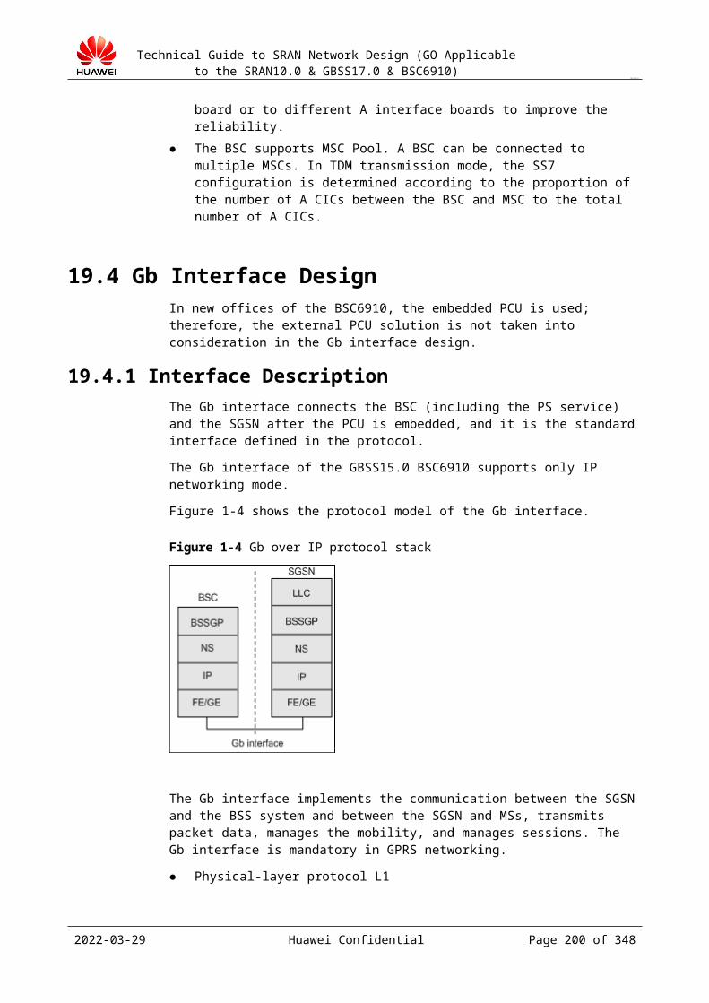
Technical Guide to SRAN Network Design (GO Applicable to the SRAN10.0 & GBSS17.0 & BSC6910)
CONFIDENTIAL
For details about signaling link design of the Lb interface, see section 19.2.5 "Signaling Configuration Principles."
19.8 BTS Homing AllocationBTS homing and TRX homing are designed according to the network planning design made by network planning personnel. When performing network planning, network planning personnel plan the allocation of BTSs and TRXs in various BSCs but do not complete the module-level planning. To balance the processing capabilities of various BSC modules and improve anti-impact and anti-risk capabilities, allocate BTSs among modules properly to implement load balancing. That is, distribute BTSs in a continuous manner between BSCs but distribute BTSs in a discontinuous manner within a BSC and between boards in large sites.
Design principles:
The number of TRXs needs to meet the designed specifications of GMPS and GEPS subracks.
The number of TRXs needs to meet the required board processing specification. The traffic carried by each module and BHCA do not exceed 60% of the designed
specification. Certain redundant ports and capacity need to be reserved for each Abis interface board
for subsequent small-scale adjustment and expansion. The recommended redundancy is 20%, and the actual redundancy depends on the BOQ.
Plan the BTSs connected to the BSC continuously in the coverage area (unless transmission conditions do not permit). Avoid discontinuous BTS distribution in different BSCs; otherwise inter-MSC handovers increase.
Allocate the BTSs in the same LAC to the same subrack to reduce inter-module signaling traffic.
Allocate the VIP sites (hot-spot areas with heavy traffic) in an area to different Abis interface boards in a subrack in a discontinuous manner. Overlapping coverage exists between adjacent cells. Therefore, this allocation mode can minimize the impacts due to out-of-service of partial VIP sites in the same area.
In a multi-chain site (ring networking), distribute multiple chains to different boards to prevent the entire site from being out of service due to board faults. Whether to adopt this mode depends on the actual situation.
For an office that is constructed by phase, there may be many site re-homing requirements. Therefore, during initial site allocation, allocate the sites that have such a re-homing requirement to several Abis interface boards in a module and adopt centralized cabling on the DDF to reduce the workload during re-homing.
Output of the design
HLD output
BSC Name Module No BTS quantity TRX quantityBSC1 0
1
2
3
2023-04-22 Huawei Confidential Page 200 of 258
Technical Guide to SRAN Network Design (GO Applicable to the SRAN10.0 & GBSS17.0 & BSC6910)
CONFIDENTIAL
LLD output (work out LLD based on the LLD template)
BTS name BTS configuration Module No Board No Port NoS2/2/2
2023-04-22 Huawei Confidential Page 201 of 258

Technical Guide to SRAN Network Design (GO Applicable to the SRAN10.0 & GBSS17.0 & BSC6910)
CONFIDENTIAL
20 Clock Synchronization Design
20.1 Design Overview20.1.1 Purpose of the Design
Select a proper clock source according to the situation of the customer. Design a networking diagram and a proper clock synchronization route according to the
clock source position, NE position, and transmission environment. Design a clock connection diagram, instructing project implementation.
20.1.2 Input of the DesignType of the clock source
20.2 Clock Description20.2.1 Definition of Synchronization
Synchronization indicates that two or more signals keep a specific relationship in frequency or phase. That is, the phase difference or frequency difference of two or more signals at the same moment keeps within a tolerable range.
Clock synchronization generally refers to frequency synchronization. The frequency of a signal is on the reference frequency. Initial moment does not require consistency.
Time synchronization is also called moment synchronization, indicating an absolute time synchronization. This means that the initial moment of a signal is consistent with the Universal Time Coordinated (UTC).
20.2.2 SyncE The SyncE technology is defined in the ITU-T G.8262 protocol. This technology inherits
the basic clock synchronization theory of the SDH and PDH networks. The downstream NEs obtain and trace the clock of the upstream NEs by restoring the clock from the serial
2023-04-22 Huawei Confidential Page 202 of 258

Technical Guide to SRAN Network Design (GO Applicable to the SRAN10.0 & GBSS17.0 & BSC6910)
CONFIDENTIAL
data streams received on the physical layer. The clock is extracted and restored from the Ethernet physical layer, irrelevant to the specific service of the upstream NEs.
SyncE is compliant with the constraints and requirements of SyncE specified in the G.8261, G.8262, and G.8264 protocols.
SyncE is available for commercial usage in GBSS15.0 or later. Intermediate transmission devices are required to support the SyncE.
20.2.3 IEEE 1588 V2 The initial edition of the IEEE 1588 (Precision Time Protocol (PTP) used in
measurement and control systems) was developed by John Edison from the Agilent Laboratories and 12 persons from other companies and organizations. It was approved by the IEEE in November 2002.
The IEEE 1588 defines the PTP protocol for the standard Ethernet. The accuracy reaches microsecond level. In 2008, the second edition of PTP focused on improving the accuracy of frequency synchronization and minimizing forward delay between the intermediate devices.
The IEEE 1588 is intended to synchronize the independent clocks running in measurement and control systems. This protocol applies to the IP RAN and can implement high-precision frequency synchronization even time synchronization between the clock server (for example, IP Clock 3000) and the NodeB.
The second edition of the IEEE 1558 is compliant with the G.8265.1 and IEEE 1588 V2. The G.8265.1 is released by the ITU for the synchronization of the layer-3 unicast frequency in IEEE 1588. It supports interworking with servers of other vendors. The IEEE 1588 V2, but does not support interworking with servers of other vendors.
NOTEHuawei's clock over IP proprietary protocol is not described here. Do not use it.
20.2.4 Advantages and Disadvantages of Clock Protocols
Clock Source
The following clock sources are available:
Building Integrated Timing Supply System (BITS) clock Clock obtained from the A interface Local free-run clock Clock over IP (Huawei proprietary protocol) SyncE IEEE 1588 V2
Comparison of synchronization technologies
Technology
Frequency Synchronization
Time Synchronization
Advantage Disadvantage Remarks
Clock over IP (Huawei proprietary
√ × Supports transparent transmission
Not support time synchronization.
The IP Clock 1000 serves as a clock server and the NodeB/BTS
2023-04-22 Huawei Confidential Page 203 of 258
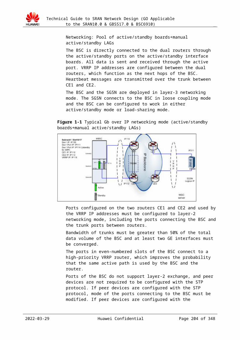
Technical Guide to SRAN Network Design (GO Applicable to the SRAN10.0 & GBSS17.0 & BSC6910)
CONFIDENTIAL
Technology
Frequency Synchronization
Time Synchronization
Advantage Disadvantage Remarks
protocol)
Not recommended
3900 series base stations later than GBSS9.0 do not support this function.
The BTS3012 still supports this function.
across the bearer network and has low requirements on the intermediate devices.
serves as a client. Clock information can be transmitted on the IP bearer network, reflecting high adaptability. Besides network QoS, the Clock over IP does not have other special requirements on the IP bearer network and therefore network reconstruction is not required.
This technology is mature and application in market is in a long time.
The clock recovery quality is vulnerable to delay, jitter, and packet loss on the bearer network.
This protocol is a Huawei proprietary protocol and does not support time synchronization. In the same condition, use the IEEE 1588 V2.
Occupies Iub downlink bandwidth resource. Normal, 30 kbit/s; max: 50 kbit/s.
SyncE √ × This clock is obtained from the physical layer, irrelevant to upper layer services. Connectivity is good.
Not support time synchronization.
The Ethernet physical media conversion devices or packet switched (PS) devices located between the Ethernet clock source and the NodeB/BTS (namely, the client) must support SyncE. Otherwise, interruption occurs and the clock cannot be allocated to the lower layer NEs.
This technology is mature and clock recovery quality is good and is not vulnerable to packet loss and
In addition to the RNC and NodeB, the RAN network also requires intermediate devices, such as the hub and LAN
The NodeB/BTS and other intermediate NEs (for example, TGW1000) support SyncE. The NodeB/BTS supports not only hub cascade on
2023-04-22 Huawei Confidential Page 204 of 258
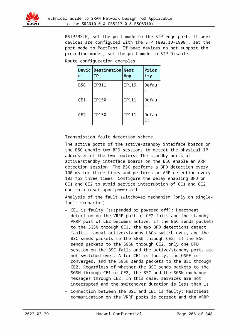
Technical Guide to SRAN Network Design (GO Applicable to the SRAN10.0 & GBSS17.0 & BSC6910)
CONFIDENTIAL
Technology
Frequency Synchronization
Time Synchronization
Advantage Disadvantage Remarks
jitter. switch to support clock transparent transmission on the physical layer or clock regeneration.
the Iub interface but also allocation of the SyncE downstream clock. However, if other NEs exist between the NodeB/BTS and the downstream clock, the intermediate NEs must support SyncE.
Not occupy radio bandwidth.
SyncE is not supported when the transmission rate is set to 10 Mbit/s.
IEEE 1588 V2
√ √ If frequency synchronization is used, transparent transmission across the bearer network is supported and the requirement on the intermediate devices is low.
If time synchronization is used, all intermediate devices must be upgraded to support IEEE 1588.
The clock server (for example, Huawei IP Clock 1000) that supports IEEE 1588 V2 serves as a clock source and the NodeB/BTS serves as a client. If frequency synchronization is used, either the clock server or the NodeB/BTS needs to support IEEE 1588 V2. Besides network QoS, the IEEE 1588 V2 does not have other special requirements on the IP bearer network and therefore network reconstruction is not required.
Supports frequency synchronization and time synchronization and meets the requirements of the LTE TDD on clock.
The clock recovery quality is vulnerable to delay, jitter, and packet loss on the bearer network.
If time synchronization needs to be used, in addition to the clock server and NodeB/BTS, all intermediate devices (including microwave devices, routers, and L2 switches) must support IEEE 1588 V2.
IEEE 1588 V2 is a standard protocol, supporting
Occupies Iub downlink bandwidth resource. Normal,
Time synchronization is not planned for the NodeB/BTS.
2023-04-22 Huawei Confidential Page 205 of 258
Technical Guide to SRAN Network Design (GO Applicable to the SRAN10.0 & GBSS17.0 & BSC6910)
CONFIDENTIAL
Technology
Frequency Synchronization
Time Synchronization
Advantage Disadvantage Remarks
interconnection of devices of manufacturers.
20 kbit/s; max: 40 kbit/s.
20.2.5 QoS Requirements of Clock ProtocolsTable 20-1 Requirements on clock accuracy
Clock Synchronization Over IP
Index Index Value
Remarks
Clock over IP (Huawei proprietary protocol)
Jitter < 20 ms -
Packet loss rate < 1% -
SyncE Frequency accuracy of the input clock
(+ 4.6 ppm, – 4.6 ppm)
Similar to E1/T1, SyncE is obtained from the physical layer and therefore SyncE does not have special requirements on the QoS of the data bearer network.
According to the G.8262 protocol, the frequency accuracy of the input SyncE clock must be between + 4.6 ppm and – 4.6 ppm.
IEEE 1588 V2 Jitter ≤ 20 msIf the jitter is great, the frequency deviation of the BTS and the clock source is great. When the frequency deviation is greater than 0.05 ppm, the clock is unlocked.
Packet loss rate ≤ 1% 1. When the packet loss rate is great, clock packets of the timestamp are lost. This results in great frequency deviation.2. When the packet loss rate is great, negotiated packets and the great period packet are lost. This results in interruption of clock links.
2023-04-22 Huawei Confidential Page 206 of 258
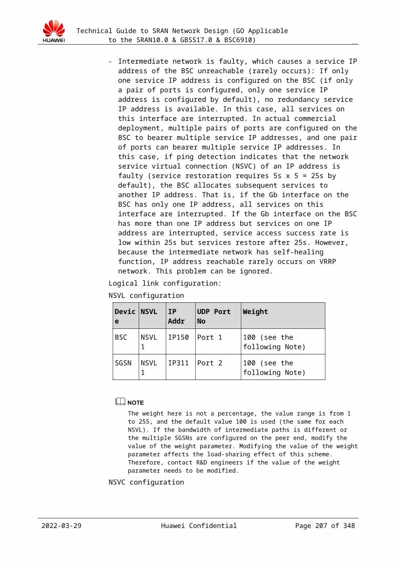
Technical Guide to SRAN Network Design (GO Applicable to the SRAN10.0 & GBSS17.0 & BSC6910)
CONFIDENTIAL
Clock Synchronization Over IP
Index Index Value
Remarks
Delay ≤ 60 ms No impact
20.3 Clock Source SelectionClock source selection is subject to the requirements of operators.
Select a clock source as follows:
In A over IP, the BTS can obtain only the BITS clock because it cannot obtain the line clock on the A interface.
In Abis over IP, the BTS adopts IEEE 1588 V2, SyncE, or IP Clock.
20.4 Clock Design in Abis over TDM ModeA clear networking diagram of a clock source and the BSC needs to be drawn.
To use a BITS clock, connect the clock cable from the BITS to the clock interface on the panel of the GGCU board.
Clock networking in this mode is simple. If an operator puts forward a special clock source, you need to confirm the principle of the special clock source with the operator and make a drawing specific to the special clock source.
Figure 20-1 shows how to obtain a clock over the A interface.
Figure 20-1 Clock networking instance 1
Figure 20-2 shows how to obtain a clock on the backbone network.
2023-04-22 Huawei Confidential Page 207 of 258
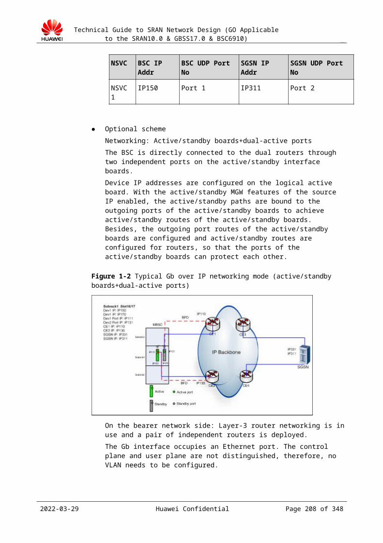
Technical Guide to SRAN Network Design (GO Applicable to the SRAN10.0 & GBSS17.0 & BSC6910)
CONFIDENTIAL
Figure 20-2 Clock networking instance 2
20.5 Clock Design in Abis over IP ModeDesign Principles
Determine a clock in Abis over IP mode according to the BSC, BTS, and bearer information.
In Abis over MSTP, the BTS obtains the line clock over MSTP to implement clock synchronization.
In Abis over FE/GE, the BTS adopts IEEE 1588 V2 or SyncE to implement clock synchronization.
In Abis over microwave, if the microwave device has clock information, the BTS obtains a line clock through microwave. Otherwise, adopt IEEE 1588 V2 or SyncE.
In Abis over satellite, the BTS adopts GPS to implement clock synchronization.
Design Guidelines
Determine a clock in Abis over IP mode according to the BSC, BTS, and bearer information. See section "Scheme of Interface Clock Synchronization."
In Abis over MSTP, the BTS obtains the line clock over MSTP to implement clock synchronization.
In Abis over FE/GE, the BTS adopts Clock over IP to implement clock synchronization. In Abis over microwave, if the microwave device has clock information, the BTS obtains
a line clock through microwave. Otherwise, the BTS adopts Clock over IP. In Abis over satellite, the BTS adopts GPS to implement clock synchronization.
Scheme of Interface Clock Synchronization
All radio data services require frequency accuracy. The BTS guarantees stable RF by means of clock synchronization. Currently, the GSM requires 0.05 ppm frequency accuracy.
After the GSM network is constructed into an IP network, the BTS cannot obtain a clock through a physical link. This is because the IP network is an asynchronous network. Therefore, the clock needs to be obtained in a new mode for the BTS to ensure clock synchronization on the air interface. Furthermore, the BSC does not lock the clock and therefore the BSC does not require clock synchronization after IP construction. Table 20-1 lists the schemes recommended for clock synchronization under GSM IP construction.
2023-04-22 Huawei Confidential Page 208 of 258
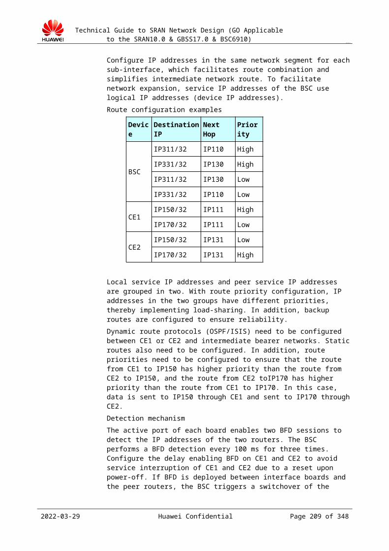
Technical Guide to SRAN Network Design (GO Applicable to the SRAN10.0 & GBSS17.0 & BSC6910)
CONFIDENTIAL
Table 20-1 Schemes recommended for clock synchronization under GSM IP construction
Networking Clock Synchronization Scheme Recommended for the BTS
Clock Synchronization Scheme Recommended for the BSC
GSM BSS all IP construction (IP over FE)
Abis over MSTP/PTN
The BTS obtains a line clock over MSTP/PTN to implement clock synchronization.
The BSC does not require clock synchronization.
Abis over FE/GE The BTS adopts IEEE 1588 V2 or SyncE to implement clock synchronization.
Abis over microwave
If the microwave device has clock information, the BTS obtains a line clock through microwave. Otherwise, the BTS adopts IEEE 1588 V2 or SyncE.
Abis over satellite The BTS adopts GPS to implement clock synchronization.
GSM BSS A interface IP construction
Abis over TDM The BTS traces the BSC clock.
The BSC adopts the BITS clock to provide a line clock for downstream BTSs.
GSM BSS Gb interface IP construction
A over TDM The BTS traces the BSC clock.
The BSC adopts a line clock and locks the clock that serves the SGSN.
The following section uses the MSTP-based IP networking as an example.
Figure 20-2 shows the MSTP-based Abis IP solution. In this solution, the BSC and BTS connect to the MSTP device over the FE interface. The MSTP device encapsulates Ethernet frames into the VC trunk, whose bandwidth is shared by multiple BTSs.
This solution is applicable to a GSM network that an SDH network or MSTP network operator is constructing. The operator can upgrade the SDH network into an MSTP network, therefore providing Ethernet access.
If the BTS and MSTP reside in the same site, the BTS connects to the MSTP over an electrical FE interface and obtains the clock from the MSTP. If the BTS and MSTP reside in different sites, the BTS connects to the MSTP over an optical FE interface and obtains the external clock of the MSTP through an E1 link free of services.
2023-04-22 Huawei Confidential Page 209 of 258
Technical Guide to SRAN Network Design (GO Applicable to the SRAN10.0 & GBSS17.0 & BSC6910)
CONFIDENTIAL
Figure 20-2 MSTP-based GSM IP solution
Currently, the transmission bearer network supports MSTP, PSTN, or L2/L3 networking. In Abis over MSTP, the BTS obtains the line clock over MSTP to implement clock synchronization. For details, see Figure 20-2. In Abis over L2/L3 networking, the BTS adopts Clock over IP (supporting the IEEE 1588 V2) to implement clock synchronization of the BTS. The following section describes Clock over IP and the design principle.
20.6 Design of the IP Clock ServerIntroduction to Clock over IP (Supporting the IEEE 1588 V2)
The Clock over IP (supporting the IEEE 155 V2) is a solution for BTS clock synchronization. The Clock over IP can be classified into IP Clock Server and IP Clock Client. The IP Clock Server obtains the reference clock source from other devices, such as the GPS or BITS, and delivers the clock information to the BTS (namely, the IP Clock Client) by using a clock packet on the IP network. The BTS performs adaptive processing of the IP clock packet to obtain the clock information.
Each IP clock packet occupies a certain bandwidth. On a rent network or in satellite transmission, continuously sending IP clock packets may increase transmission cost and even affect services in busy hours of the network. In the GBSS system, operators can customize the time of sending IP clock packets to ensure that IP clock packets are sent during light network load. The BTS of the GBSS system can retain 0.05 ppm frequency accuracy within 90 days and periodically send IP clock packets, not only reducing bandwidth use but also preventing BTS out-of-sync. Figure 20-1 shows the networking of Clock over IP.
2023-04-22 Huawei Confidential Page 210 of 258

Technical Guide to SRAN Network Design (GO Applicable to the SRAN10.0 & GBSS17.0 & BSC6910)
CONFIDENTIAL
Figure 20-1 IP Clock synchronization networking
Table 20-1 describes the support for 2G-based 1588v2 clocks.
Table 20-1 Support for 2G-based 1588v2 clocks
System
IP Clock Type
Support Clock Redundancy Backup or Not
Address 1 Address 2 Synchroniz
ation Mode
2G
1588v2 Layer-3 unicast
YesIP address of the IP clock server
IP address of the IP clock server
Intermittent synchronization (command: SET BTSIPCLKPARA)
1588v2 Layer-2 multicast
Yes
MAC address of the IP clock server
MAC address of the IP clock server
Default continuous synchronization
2G networks support 1588v2 Layer-3 unicast and 1588v2 Layer-2 multicast. The clock mode widely used on the live network is 1588v2 Layer-3 unicast.
You can run the SET BTSCLK command on the maintenance console to set Clock Type to IP_TIME(IP Clock).
You can run the SET BTSIPCLKPARA command on the maintenance console to set Clock Protocol Type to HW_DEFINED(Huawei User-defined) or PTP(PTP Protocol). The BTS, however, supports only the PTP clock mode currently.
Design principle of the IP Clock Server (Huawei's IP Clock Server product is IPCLK3000)
2023-04-22 Huawei Confidential Page 211 of 258
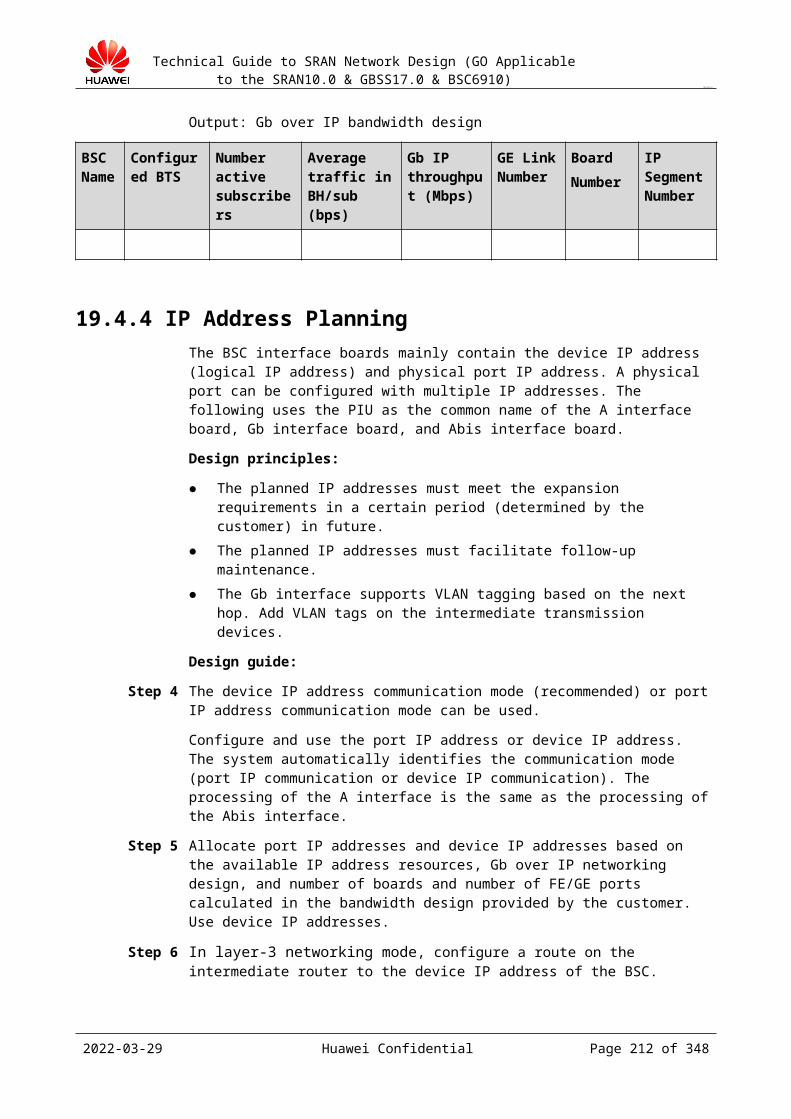
Technical Guide to SRAN Network Design (GO Applicable to the SRAN10.0 & GBSS17.0 & BSC6910)
CONFIDENTIAL
NOTEFor details about the IPCLK3000 product and the configuration guide, obtain the IPCLK3000 Description and IPCLK3000 User Guide at http://support.huawei.com and http://3ms.huawei.com.
IPCLK3000 supports the following clock sources:− BITS clock− External 8 kHz clock provided by external devices− Global Positioning System (GPS)/Global Navigation Satellite System (GLONASS)
satellite clock− External 1 pulse per second (1PPS) clock
NOTEA built-in satellite card can be installed in IPCLK3000 to obtain GPS clock signals. GPS clock signals generated by external satellite cards can also be obtained through clock signal interfaces on the panel.
IPCLK3000 clock performance indicators
Table 20-2 lists IPCLK3000 clock performance indicators.
Table 20-2 IPCLK3000 clock performance indicators
Name Value
Maximum number of supported clients
Frequency synchronization: 512 NodeBs, eNodeBs, or BTSsTime synchronization: 512 WiMAX BTSs
Maximum picket sending frequency
IEEE 1588 V2: 128 packet per second (pps)
Maximum bandwidth occupied by each signal
IEEE 1588 V2:Frequency synchronization: normal: 12 kbit/s; max: 190 kbit/sTime synchronization: normal: 14 kbit/s; max: 210 kbit/s
Frequency retention hour after clock sources are lost
7 days
Frequency retention precision after clock sources are lost
(+ 0.016 ppm, – 0.016 ppm)
Network topology
Layer-3 networking, layer-2 networking of the private network, and the Internet public networking are supported. Use the layer-3 networking.
The IP clock server accesses the network through a layer-3 router. If VLAN tags need to be configured, add VLAN tags to intermediate transmission devices.
The IP clock server accesses the network through a layer-2 switch. If VLAN tags need to be configured, add VLAN tags to intermediate transmission devices.
2023-04-22 Huawei Confidential Page 212 of 258

Technical Guide to SRAN Network Design (GO Applicable to the SRAN10.0 & GBSS17.0 & BSC6910)
CONFIDENTIAL
The IP clock server supports VLAN configurations. A maximum of 512 VLANs can be configured on the IP clock server. On the BTS side, the number of base stations needs to be less than 50 for a VLAN.
Capacity planningIn frequency synchronization, one IPCLK3000 can support 512 NodeBs, eNodeBs, or BTSs.IPCLK3000 is an independent case-shaped device. The actual number of IPCLK3000s to be deployed depends on the number of Clients and the backup relationship between IPCLK3000s. Generally, 500 BTSs share one IPCLK3000.
IP address planningIP addresses of IP clock servers need to be configured on the radio BTS side. You can plan IP addresses based on the IP address schemes for the layer-3 and layer-2 networking modes. Generally, two IP addresses are planned.− Run the SET ETHIP command on the IP clock LMT to configure service IP
addresses of IPCLK3000 for matching service ports with Port Type set to SERVICE.
− Run the SET ETHIP command on the IP clock LMT to configure operation and maintenance IP addresses of IPCLK3000 for matching operation and maintenance ports with Port Type set to DEBUG.
ReliabilityTo implement 1+1 backup of reference clock sources, IP addresses of two IPCLK3000 clock servers need to be configured on the BTS side. With enhanced reliability, clock sources are still available when an IPCLK3000 is faulty.
NOTEThe two IPCLK3000 clock servers are independent. They are configured to be the primary and secondary clock server on the BTS side.
Synchronization mode on the BTSThe support for continuous and intermittent synchronizations is introduced to the MBTS in SRAN5.0. Intermittent synchronization only applies to the 1588v2 Layer-3 unicast packet mode. Use the intermittent synchronization on the live network.Intermittent synchronization is used in the following scenarios:− The transmission bandwidth is limited. (Intermittent synchronization helps save the
bandwidth.)− If the network QoS is poor in peak hours and good in off-peak hours, the
synchronization time needs to be set during peak hours and the clock needs to be locked during off-peak hours.
Matching Version of the IP Clock Server
Table 20-3 describes whether the IP clock server adaptive synchronization protocols are supported on the hardware platform or the old hardware platform.
Table 20-3 Whether the IP clock server adaptive synchronization protocols are supported on the hardware platform or the old hardware platform
IP Clock Server IP Clock (Customized by Huawei)
1588 V2 (L3 Transparent Transmission)
Hardware Platform
V100R001 √ Old hardware
2023-04-22 Huawei Confidential Page 213 of 258
Technical Guide to SRAN Network Design (GO Applicable to the SRAN10.0 & GBSS17.0 & BSC6910)
CONFIDENTIAL
IP Clock Server IP Clock (Customized by Huawei)
1588 V2 (L3 Transparent Transmission)
Hardware Platform
platform V100R002 √
V200R002 √ √ New hardware platform
V100R001 and V100R002 apply only on the old hardware platform and they cannot be upgraded to V200R002.
V100R002 is a non-productive version and is an upgrade version of V100R001. V200R002 applies on the new hardware platform. All devices to be delivered have used this version
since August 1, 2009.
Table 20-4 describes whether the GSM products support the IP adaptive synchronization protocols.
Table 20-4 Whether the GSM products support the IP adaptive synchronization protocols
IP Clock (Customized by Huawei)
1588 V2 (L3 Transparent Transmission)
1588 V2 over MAC
GBSS15.0 √ √
Because the hardware logic resource of the GSM BTS3900 is limited, the GBSS15.0 supports only 1588 V2.
IP clock version under various GSM scenarios
Create an IP clock server.
If an IP clock server is required, V200R002 is delivered.
2023-04-22 Huawei Confidential Page 214 of 258
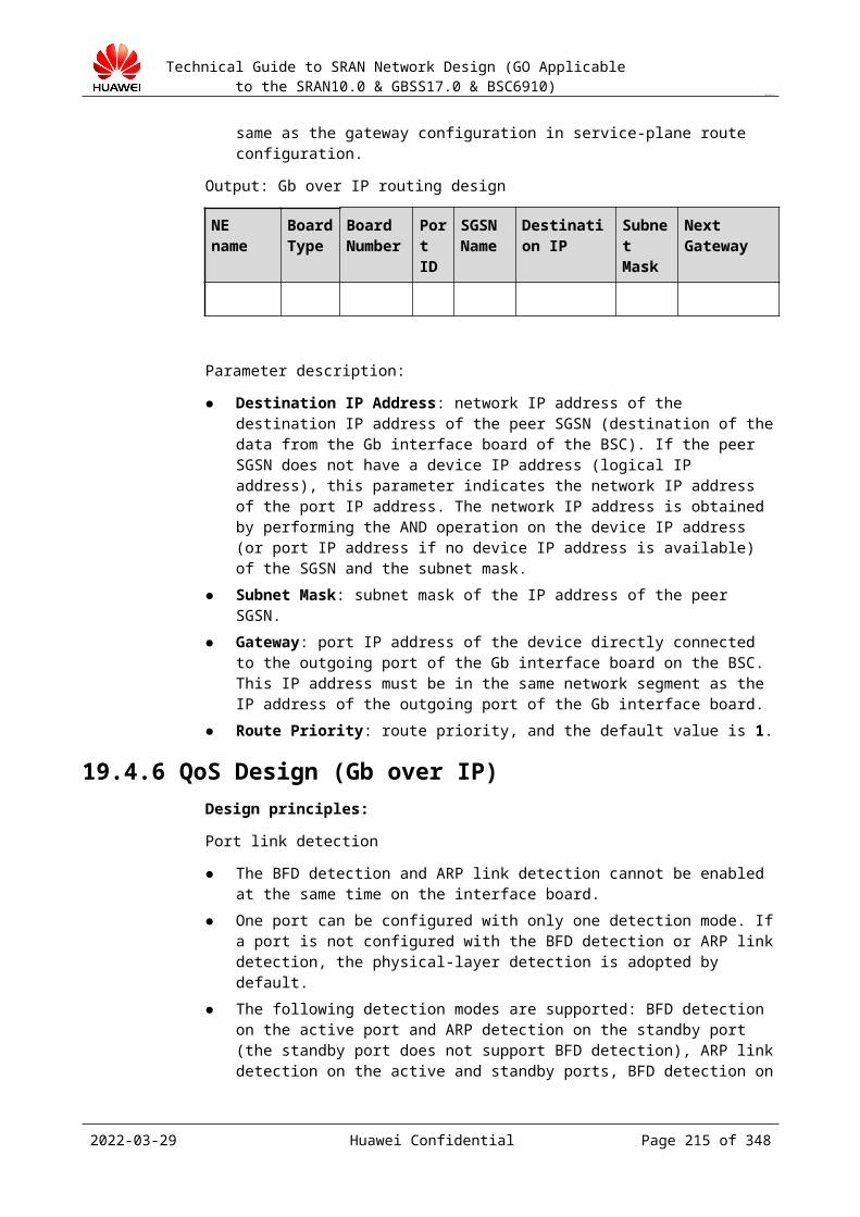
Technical Guide to SRAN Network Design (GO Applicable to the SRAN10.0 & GBSS17.0 & BSC6910)
CONFIDENTIAL
21 Time Synchronization Design
21.1 Design Overview 21.1.1 Purpose of the Design
Select a proper time synchronization source. Design a networking scheme of time synchronization according to transmission
information and NE position. Design IP addresses for time synchronization.
21.1.2 Input of the DesignType of time synchronization, and position and IP address of the M2000 server
21.2 Description of Time SynchronizationTime synchronization indicates that the time of communication devices or computer devices on the communication network is UTC-based and the time offset is small enough, for example, 100 ms.
A time synchronization network works in client/server mode and adopts a leveled time server to implement time synchronization. Normally, a time synchronization source is obtained from the standard time source.
On a BSS network, time synchronization means that the NMS synchronizes with BSS NEs. In this way, the NMS can record the time of generating alarms and events of each NE, facilitating fault analysis and performance analysis.
21.3 NTPNetwork Time Protocol (NTP) is a complex time synchronization protocol across WAN and LAN, specific to microsecond. The NTP can be used in two modes: broadcast and
2023-04-22 Huawei Confidential Page 215 of 258

Technical Guide to SRAN Network Design (GO Applicable to the SRAN10.0 & GBSS17.0 & BSC6910)
CONFIDENTIAL
client/server. The later mode has higher accuracy than the former one. In client/server mode, the NTP server needs to exchange NTP packets with NEs requiring tine synchronization, to obtain the time offset between the NTP server and the NEs. The client/server mode has 1 to 10 ms accuracy. Therefore, this mode is widely used in network time transmission.
NTP uses UDP transmission and adopts the standard port number 123.
Simple Network Time Protocol (SNTP) is a simplified NTP protocol.
21.4 Selection of a Time Synchronization Source
Currently, the following time synchronization sources are used:
GPS time synchronization source. Internet-based time synchronization source. The Internet provides many NTP-based time
servers. You can access the servers to implement time synchronization.
Selection of a time synchronization source is subject to the time source provided by an operator.
21.5 Transmission ModeTransmission mode is classified into wireless transmission and wired transmission (DCN and DDN). DCN is a TCP/IP-based network for internal transmission. It features convenient networking, little investment, high security, and high reliability. Therefore, DCN is used in mobile networks for time synchronization. DDN, a private transmission network, requires high cost.
21.6 Typical NetworkingFigure 21-1 shows a typical networking for BSS time synchronization.
Figure 21-1 Typical networking for time synchronization
2023-04-22 Huawei Confidential Page 216 of 258
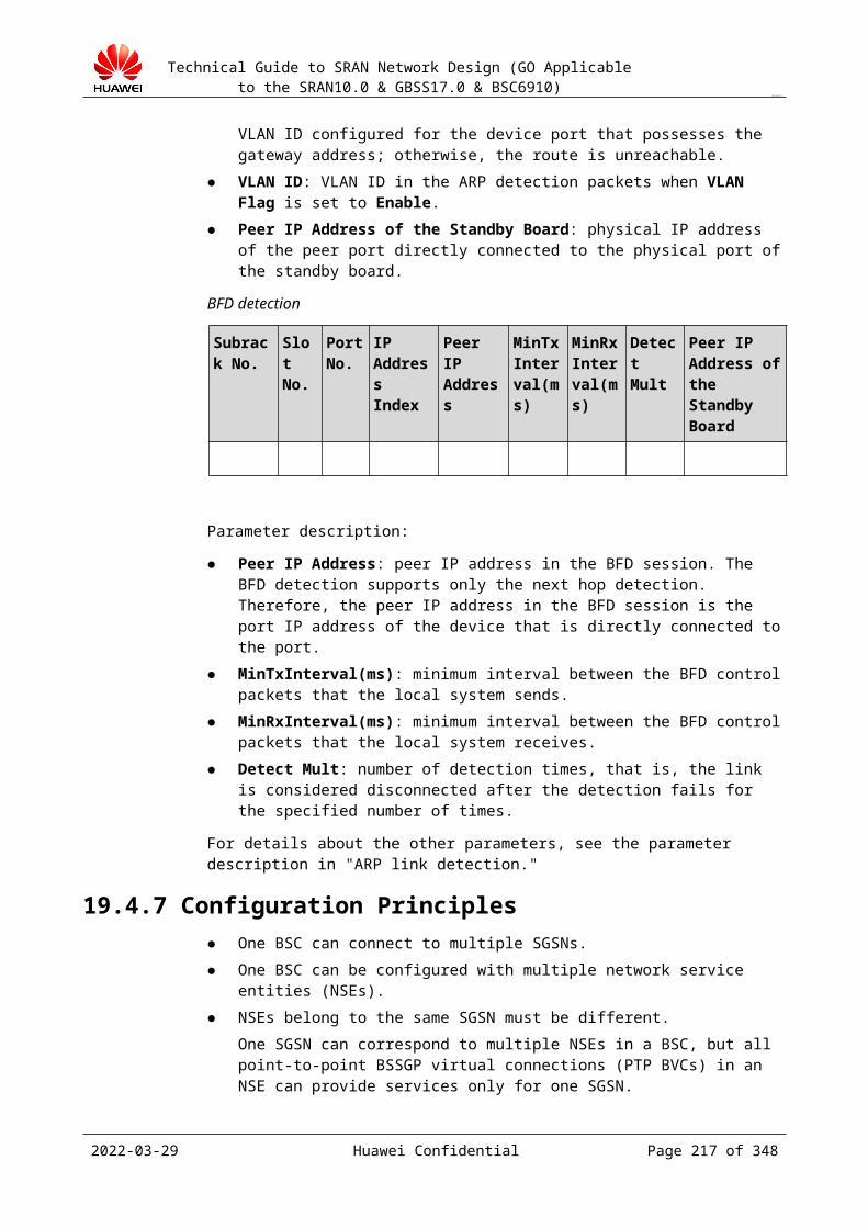
Technical Guide to SRAN Network Design (GO Applicable to the SRAN10.0 & GBSS17.0 & BSC6910)
CONFIDENTIAL
21.7 Typical ApplicationThe NTP server of the OMU of the BSC is configured with the IP address of the M2000. The NTP time is obtained from the M2000.
One BSC can be configured with addresses of multiple NTP servers, with the port number being 123.
The following table lists the NTP servers and the port number.
BSC Name NTP Server Port NoBRBSC10 10.123.0.4 123
BRBSC10 10.123.0.5 123
BRBSC10 10.123.0.6 123
The configuration of daylight saving time (DST) varies with areas. The following tables describe the DST configuration of a north European country.
ZONET DST SM SMONTHGMT+1 YES Week March
SDAY SWSEQ SWEEK STLast Sunday 02:00:00
EM EMONTH EDAY EWSEQWeek October Last
EWEEK ET TOSunday 03:00:00 60
2023-04-22 Huawei Confidential Page 217 of 258
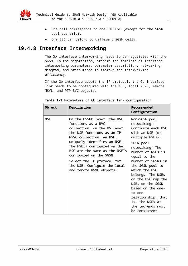
Technical Guide to SRAN Network Design (GO Applicable to the SRAN10.0 & GBSS17.0 & BSC6910)
CONFIDENTIAL
22 Function Design
22.1 Design of Broadcast Solutions for Cells22.1.1 Standard Broadcast
The cell broadcast is a broadcast short message (SM) service specific to the GSM system. Within a same period, the cell broadcast uses radio CBCH channels to send messages to a specific coverage area in a single direction under certain conditions. In this way, all MSs on a network can receive messages and do not need to respond to the received messages.
The simple cell broadcast provides the simple cell broadcast service without the CBC system. The broadcast information includes the cell name, weather information, and social commonweal information.
Table 22-1 NEs involved in the cell broadcast system
Acronyms and Abbreviations
Full Name
BTS Base transceiver station
BSC Base station controller
CBC Cell broadcast center
CBS Cell broadcast server
CBT Cell broadcast terminal
CBE Cell broadcast entity
The cell broadcast system comprises the CBE, CBC, BSC, BTS, and MS. Each NE provides the following functions:
The CBE is an interface connecting external message sources and the GSM network. It records cell broadcast information and encodes and formats the cell broadcast information.
The CBC collects and stores formatted cell broadcast information from the CBE and then sends the broadcast information to specific BSCs based on scheduling information
2023-04-22 Huawei Confidential Page 218 of 258
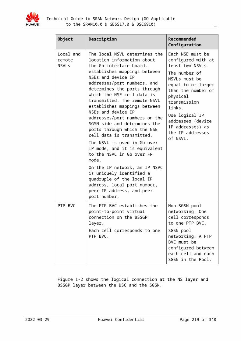
Technical Guide to SRAN Network Design (GO Applicable to the SRAN10.0 & GBSS17.0 & BSC6910)
CONFIDENTIAL
in the broadcast information. In addition, the CBC manages broadcast information on the BSC, for example, deleting outdated information and querying the status of broadcasting information in a cell.
The BSC schedules and maintains broadcasting information. It also needs to maintain the CBCH status.
The BTS distributes cell broadcast information over the Um interface. The MS receives and displays cell broadcast information.To enable the cell broadcast, a CBCH channel needs to be configured on a cell. The CBCH channel is a logical channel and occupies the same physical channel with the SDCCH. Therefore, the CBCH channel can be configured in the following two ways: SDCCH/8+CBCH: used for a cell whose channel type is set to the non-combined BCCH
channel BCCH+CCCH+SDCCH/4+CBCH: used for a cell whose channel type is set to the
combined BCCH channel
For the SDCCH/8+CBCH configuration mode, select SDCCH+CBCH for Channel Type. For the BCCH+CCCH+SDCCH/4+CBCH configuration mode, select BCCH+CBCH for Channel Type.
For the SDCCH+CBCH channel configuration, set CCCH Blocks Reserved for AGCH to 0. This is because the MS needs to temporarily stop monitoring the PCH channel and to receive contents over the CBCH channel so that the MS can receive cell broadcast information. In this case, if a paging message for the MS is reported over the PCH channel, the MS cannot receive this paging message. When CCCH Blocks Reserved for AGCH is not set to 0, the MS can receive information over the CBCH channel within the AGCH channel period and can receive all paging messages. For the BCCH+CBCH channel configuration, CCCH Blocks Reserved for AGCH needs not to be set to a value other than 0.
The SDCCH+CBCH channel can be configured only on any of timeslots 0 to 3 of the carrier. The BCCH+CBCH channel can be configured only on time slot 0 of the carrier.
Due to codec constraints, if the CBCH channel is configured on the time slot involved in frequency hopping, the number of frequencies of frequency hopping configured on the time slot needs to be less than 32.
Network design: The network design of the cell broadcast is simple. The CBC connects to the BSC over the CB interface. The XPU board of the BSC connects to the CBC over the Ethernet network interface. The network design needs to consider the location of the CBC and BSC and transmission resources. Figure 22-2 shows the network design diagram.
Figure 22-2 Network topology of the cell broadcast
2023-04-22 Huawei Confidential Page 219 of 258
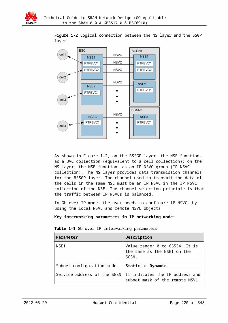
Technical Guide to SRAN Network Design (GO Applicable to the SRAN10.0 & GBSS17.0 & BSC6910)
CONFIDENTIAL
The BSC directly interwork with the CBC over the IP network. Specifically, the BSC accesses the CBC network using a network cable from the port on the IP interface board (depending on the port enabled in Configure boards attributes on the IP interface board. Figure 22-3 shows the physical cable connection diagram.
Figure 22-3 Cable connection diagram between the interface board and the CBC
NOTEConfigure cell broadcast data based on the product feature configuration guide without additional data configuration for the IP interface board.
Table 22-1 Key parameter configurations
IP address of the CBC
Negotiated with peer equipment
Subnet mask Negotiated with peer equipment
MAC address Negotiated with peer equipment
2023-04-22 Huawei Confidential Page 220 of 258
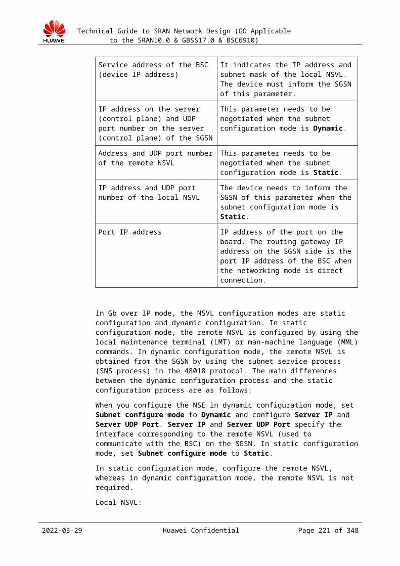
Technical Guide to SRAN Network Design (GO Applicable to the SRAN10.0 & GBSS17.0 & BSC6910)
CONFIDENTIAL
Table 22-2 Parameter configurations
Name Description Command Impact NE
Channel Type
This parameter specifies the channel type of the timeslot on the TRX. The channel type of timeslot 0 must not be set, because the combined BCCH is configured by default. The channel type of other timeslots can be set to full-rate TCH or half-rate TCH.
SET BTSCHNFALLBACK (Mandatory)
BTS
CCCH Blocks Reserved for AGCH
BS-AG-BLKS-RES, indicating the number of the CCCH message blocks reserved for the AGCH. After the CCCHs are configured, the value of this parameter indicates the actual seizure rates of the AGCHs and the PCHs over the CCCHs.
SET GCELLIDLEBASIC (Optional)
Cell
SMCBC DRX
This parameter specifies whether to support the discontinuous reception mechanism (DRX). To reduce the power consumption, the DRX is introduced into the GSM Specification. MSs supporting the DRX can consume less power to receive interested broadcast messages. This prolongs the service time of MS batteries. BSCs supporting the DRX must send scheduling messages to MSs so that the MSs can use the DRX function. The period occupied by broadcast messages that are contained in a scheduling message is called a scheduling period. In the sending sequence, a scheduling message contains the description of each short message to be broadcast and the position of each broadcast message in the scheduling period.
SET GCELLOTHEXT (Optional)
Cell
Support Cell Broadcast
This parameter specifies whether the BSC6910 supports the cell broadcast function.
ADD GCNOPERATOR (Optional)
BSC6910
2023-04-22 Huawei Confidential Page 221 of 258

Technical Guide to SRAN Network Design (GO Applicable to the SRAN10.0 & GBSS17.0 & BSC6910)
CONFIDENTIAL
BSC IP This parameter specifies the IP address for the communication between the BSC and the CBC. It must be consistent with the configured IP address of the CPU board.
ADD GCBSADDR (Mandatory)
BSC6910
BSC Port This parameter specifies the port number used for the communication between the BSC6910 and the CBC.
ADD GCBSADDR (Mandatory)
BSC6910
BSC GateWay IP
When the BSC supports the standard cell broadcast function, it sends cell broadcast messages using the IP address specified by this parameter.
ADD GCBSADDR (Mandatory)
BSC6910
CBC ITF Para
The value of this parameter must be translated into binary digits. The following describes each bit of the value: Bit 0: phase flag Bit 1: message type flag Bit 2: cell-list flag Bit 3: whether to carry a
recovery indication Bit 4: whether to carry the
cell flag Bit 5: whether to carry a
recovery indication during the reset procedure
ADD GCBSADDR(Optional)
BSC6910
Support Cell Broadcast Name
This parameter specifies whether to broadcast the cell name.
SET GCELLSBC (Optional)
Cell
CBC IP This parameter specifies the IP address of a CBC.
ADD GCBSADDR(Mandatory)
BSC6910
CBC Port This parameter specifies the port number at the CBC side in the communication with the BSC6910.
ADD GCBSADDR(Mandatory)
BSC6910
Broadcast Content
This parameter specifies contents of a cell broadcast message.
SET GCELLSBC(Optional)
Cell
2023-04-22 Huawei Confidential Page 222 of 258
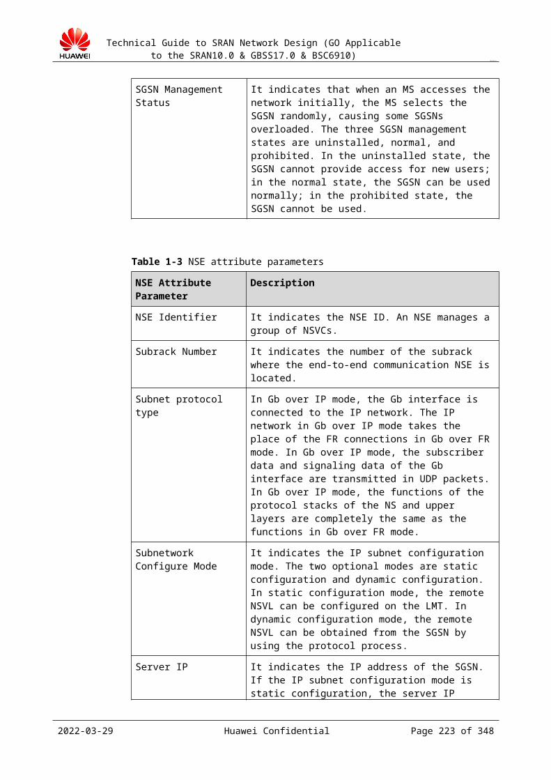
Technical Guide to SRAN Network Design (GO Applicable to the SRAN10.0 & GBSS17.0 & BSC6910)
CONFIDENTIAL
Geography Scope
This parameter specifies the geographic scope of a simple cell broadcast message. You can obtain the value of this parameter using DSP GSMSCB. Geography Scope, Code, and Update uniquely identify a cell broadcast message.
SET GCELLSBC(Optional)ADD GSMSCB(Mandatory)
Cell
Chan ID This is a key parameter for adding a simple cell broadcast message. It specifies the channel ID of a simple cell broadcast message. You can obtain the value of this parameter using DSP GSMSCB.
SET GCELLSBC(Optional)ADD GSMSCB(Mandatory)
Cell
Coding Scheme
This is a key parameter for identifying a simple cell broadcast message. It specifies the coding scheme of message contents.
SET GCELLSBC (Optional)ADD GSMSCB (Mandatory)
Cell
Broadcast Interval
This parameter specifies the time interval for a cell broadcast message.
SET GCELLSBC (Optional)
Cell
22.1.2 Simple Cell BroadcastThe simple cell broadcast provides the simple cell broadcast service without the CBC system. The broadcast information includes the cell name, weather information, and social commonweal information. To enable the simple cell broadcast service, set Support Cell Broadcast to Support Simple CB.
The simple cell broadcast provides two types of functions: cell name broadcast and cell broadcast.
The cell name broadcast enables the BSC to send a one-page-long text message to the MSs in a cell under the BSC. The text message contains the cell name. Therefore, when a roaming MS enters a new cell where the simple cell broadcast function is enabled, the MS can obtain and display the cell name. This function equates to the simple location service. The BSC will keep sending the one-page-long message, but MS users can disable this function on the MS to stop the receiving of this message. To enable the cell name broadcast function, first set Support Cell Broadcast Name to Yes and then specify parameters, such as Broadcast Content (this parameter is set to the cell name by default), Geography Scope, Chan ID, Coding Scheme, and Broadcast Interval.
The ADD GSMSCB command can be run to send a cell broadcast message to the BSC. If you send the cell broadcast message in such a way, specify ST and ET of the period during which the cell broadcast message is broadcast. The maximum size of the cell broadcast message that can be sent through the MML command is 15 pages. A cell can save a maximum of 63 pages of cell broadcast messages.
2023-04-22 Huawei Confidential Page 223 of 258

Technical Guide to SRAN Network Design (GO Applicable to the SRAN10.0 & GBSS17.0 & BSC6910)
CONFIDENTIAL
In addition, the DSP GSMSCB command can be used to query the cell broadcast messages saved in a cell; you can also run the RMV GSMSCB command to stop the broadcast of a cell broadcast message. Figure 22-1 shows the topology of the simple cell broadcast system.
Figure 22-1 Topology of the simple cell broadcast system
NOTEThe simple cell broadcast cannot be used with the cell broadcast provided by the CBC. They are mutually exclusive.The simple cell broadcast provides only simple cell broadcast services. The standard cell broadcast system is recommended for the dynamic information that is frequently changed.
22.2 Design of Radio Measurement Data Interface for Navigation (TOM-TOM)22.2.1 Overview
The radio measurement data interface for navigation (TOM-TOM) is used for real-time navigation on highways.
The TOM-TOM sends MS-related radio data collected by the BSC to the VNP, and the VNP reports the data to the third-party collection unit (CU). (The MS-related radio data includes whether the MS is within the BTS coverage area of the highway, the movement speed of the MS, and the movement direction of the MS.) The CU processes the reported, collected information, selects a proper path, and sends the path information to the GPS end user for providing guidance for the user to bypass the congested road.
The BSC and VNP used during the entire navigation are provided by the device manufacturer and the CU is from a third party.
You can configure an ENTSWITCH on the BSC. The TOM-TOM cannot be used if the switch is disabled. You can also configure the IP address of the VNP on the BSC.
For details about the function of the TOM-TOM, see the BSC6910 GSM Product Documentation.
2023-04-22 Huawei Confidential Page 224 of 258

Technical Guide to SRAN Network Design (GO Applicable to the SRAN10.0 & GBSS17.0 & BSC6910)
CONFIDENTIAL
22.2.2 Reference DocumentDeployment Guide:
The deployment guide of this feature is available on the deployment guide named BSC6910 GSM Product Documentation.
22.2.3 Limitations on SpecificationsThe TOM-TOM has the following limitations on specifications:
A BSC can connect to only one VNP. A VNP can connect to a maximum of five BSCs. Neither ARP nor BFD is supported. Neither IP paths nor logical ports can be configured. The IP PM function is not supported. Priorities of DSCP values and VLANs cannot be configured. VLANs cannot be configured based on the service flow. To differentiate the OM service
flow from the TOM-TOM service flow, use different next hops for the OM and the TOM-TOM. Then configure VLANs based on the next hops.
22.2.4 Software and Hardware ConfigurationNo new hardware configuration is added to the BSC.
The VNP interface uses the EOMU board of the BSC6910.
This feature is supported in BSC6910 V900R015 and later. Before using the feature, you need to apply for a license.
22.2.5 Networking Design
22.2.5.1 Logical NetworkingFigure 22-1 shows the logical networking for the TOM-TOM.
2023-04-22 Huawei Confidential Page 225 of 258

Technical Guide to SRAN Network Design (GO Applicable to the SRAN10.0 & GBSS17.0 & BSC6910)
CONFIDENTIAL
Figure 22-1 Logical networking for the TOM-TOM
The logical networking shows only the logical connection, but not the actual physical connection between network elements.
The BSC interworks with the VNP using the IP bearer. Subscriber events generated on the BSC are reported to the VNP over the TCP/IP (the BSC provides TCP 6200 port). Then, the VNP sends the data to a third-party server for calculation. A BSC can connect and report events to only one VNP. A VNP, however, can connect to multiple BSCs simultaneously.
The M2000, CU, and Traffic server obtain the synchronization time from the NTP server, and the BSC and VNP obtain the synchronization time from the M2000.
22.2.5.2 VNP Interface Networking DesignThe VNP interface uses the EOMU board of the BSC6910. Figure 22-1 shows the physical networking over the VNP interface.
The EOMUs are configured in active/standby mode. The Ethernet interfaces 0 and 1 of each EOMU are connected to different LAN switch ports. Two VRRP routers are configured.
Figure 22-1 Physical networking on the VNP interface
2023-04-22 Huawei Confidential Page 226 of 258
Technical Guide to SRAN Network Design (GO Applicable to the SRAN10.0 & GBSS17.0 & BSC6910)
CONFIDENTIAL
The use of the TOM-TOM feature does not cause a change to the original OMU interface networking generally, because the interface of the OMU adopts the IP transmission networking. A new logical IP address of the OMU, however, is required as a communication address of the VPN interface (see VPN logical IP address in Figure 22-1). In addition, the IP address of the peer VPN needs to be configured as the destination IP address.
The local IP address of the VNP must be different from the virtual IP address of the external network of the OMU or the fixed IP address of the external network. If the local IP address of the VNP is a logical IP address, it can be configured as a 32-bit mask, and in the same network segment or different network segments with the IP address of the OM.
Figure 22-2 shows the networking of the active/standby OMUs with a single port and directly connected routers. This networking is used only by some operators, because the networking has lower reliability, although it saves two LAN switches as compared with the networking in Figure 22-1.
Figure 22-2 Networking of the active/standby OMUs with a single port and directly connected routers
22.2.5.3 VLAN PlanningYou can configure different VLANs to distinguish the OM service flow from the TOM-TOM service flow. (This configuration is optional.)
22.2.5.4 QoS PlanningPriorities of DSCP values and VLANs cannot be configured.
22.2.6 Bandwidth DesignNone.
2023-04-22 Huawei Confidential Page 227 of 258
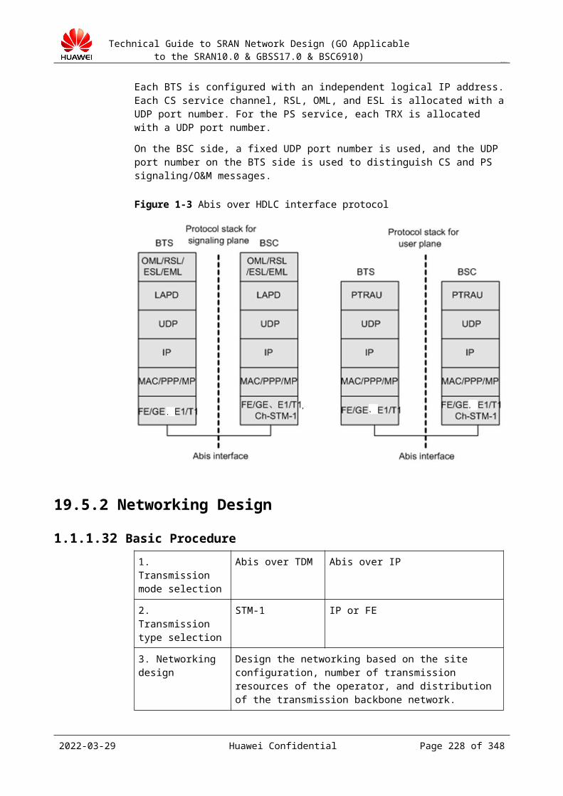
Technical Guide to SRAN Network Design (GO Applicable to the SRAN10.0 & GBSS17.0 & BSC6910)
CONFIDENTIAL
22.2.7 Time SynchronizationThe M2000, CU, and Traffic server obtain the synchronization time from the NTP server, and the BSC and VNP obtain the synchronization time from the M2000. Figure 22-1 shows the networking for time synchronization.
Figure 22-1 Networking for time synchronization
22.3 MOCN II Design
22.3.1 Overview
The principles, specifications, networking, parameter settings, and feature activation have been described in the MOCN II Feature Parameter Description. This section only describes the planning and design related to this feature.
22.3.2 Networking Design
For details, see section "Network Topology" in MOCN II Feature Parameter Description.
MOCN II achieves RAN equipment sharing, including BSC, BTS, Abis transmission resources. The core network resources cannot be shared.
The A and Gb interfaces can share interface boards and transmission on the BSC but use different logical resources, such as IP addresses and routes.
2023-04-22 Huawei Confidential Page 228 of 258

Technical Guide to SRAN Network Design (GO Applicable to the SRAN10.0 & GBSS17.0 & BSC6910)
CONFIDENTIAL
22.3.3 Capacity Planning
The MOCN II networking does not affect capacity planning of RAN resources. RAN resources are planned in the same way as in traditional networking mode. During the planning, obtain the total amount of resources required by different operators.
MOCN II does not allow operator-based configuration of Abis transmission resources. Abis transmission resources are shared and therefore the method for planning the resources is the same as the traditional one.
The A and Gb interfaces must be connected to CNs of different operators. Therefore, the bandwidths over the A and Gb interfaces are planned according to the need of each operator.
22.3.4 Interface Design
The interface networking does not change during the implementation of MOCN II. Therefore, the traditional networking modes over each interface still apply in MOCN II-enabled scenarios. For details, see chapter 19 "Transmission Interface Design."
Since the A and Gb interfaces are connected to the CNs of different operators in MOCN-enabled scenarios, the interfaces use the following configurations:
Operators use different interface boards, but the interface networking modes are the same as the traditional ones.
Operators share interface boards. The physical networking in this situation is the same as the traditional one, but multiple device IP addresses are used to distinguish operators.
Transmission resource pool is a network networking mode. The following table lists the designed specifications in the transmission resource pool mode.
The MOCN networking can be classified into operator-based independent configuration and configuration sharing among multiple operators for A interface boards.
ModeOperator-based Independent Configuration of A interface Boards (Recommended)
Configuration Sharing of A Interface Boards Among Multiple Operators
Pooled with operators distinguished
Pooled according to the number of operators or pooled with the boards belonging to the same operator.
Pooled with all boards. Configure certain number of device IP addresses for all boards and form multiple pools where physical ports can be shared or independently used and port IP addresses can be shared or independently used (in this situation, configure multiple port IP addresses). Then, transfer services to CNs of different operators according to the destination IP addresses.
2023-04-22 Huawei Confidential Page 229 of 258

Technical Guide to SRAN Network Design (GO Applicable to the SRAN10.0 & GBSS17.0 & BSC6910)
CONFIDENTIAL
Pooled without distinguishing operators
N/A
Boards in active/standby mode, two ports in load sharing mode, or an independent board can form a pool. Services are transferred to CNs of different operators according to the destination IP addresses.
22.4 Design of BSC Node Redundancy
22.4.1 Overview
The BSC Node Redundancy feature allows two BSCs to form a redundancy group. Two BSCs in a redundancy group work in 1+1 backup mode, and a BTS is connected to both BSCs. Under normal circumstances, the BTSs controlled by each BSC operate properly. If one BSC fails or all the signaling links on the A interface of one BSC are disconnected, the other BSC takes over services from the failed BSC. The following figure shows the networking diagram of two BSCs working in a redundancy group.
2023-04-22 Huawei Confidential Page 230 of 258

Technical Guide to SRAN Network Design (GO Applicable to the SRAN10.0 & GBSS17.0 & BSC6910)
CONFIDENTIAL
Unlike cold standby, the BSC Node Redundancy feature recovers services without adjusting the transmission data over interfaces or reconfiguring data. However, if a BSC switchover is triggered, all ongoing services will be interrupted because no backup data is available, but new services will not be affected. In this sense, this feature is neither hot standby nor warm standby, but a redundancy between the warm standby and cold standby.
The principles, specifications, networking, parameter configurations, and feature activation have been described in BSC Node Redundancy Feature Parameter Description. This section only describes the planning and design related to this feature.
22.4.2 ConstraintsThe design of BSC node redundancy is subject to the following constraints:
2023-04-22 Huawei Confidential Page 231 of 258

Technical Guide to SRAN Network Design (GO Applicable to the SRAN10.0 & GBSS17.0 & BSC6910)
CONFIDENTIAL
The settings of the parameters that do not support configuration synchronization must be consistent between two BSCs. These parameters include equipment parameters, BSC radio parameter, and transmission-related parameters (excluding IP address-related parameters).
To enable successful configuration synchronization, the parameters that do not support synchronization must be configured first. For example, the radio parameter settings for a dual-homed BTS can be synchronized only after Abis transmission data has been configured on the secondary-homed BSC.
If the settings of parameters that do not support configuration synchronization on the secondary-homed BSC conflict with those on the primary-homed BSC, the synchronization of parameter settings may fail. If the configuration synchronization fails, a report is displayed on the CME, reminding you to take the following measures to rectify the situation: Manually modify the parameters that do not support configuration synchronization on the secondary-homed BSC so that the parameter settings are consistent with those on the primary-homed BSC. Then, manually trigger a configuration synchronization task.Example 1:Problem description: A BTS under BSC 1 uses IP transmission, and the BSC interface board connecting BSC 1 to the BTS supports IP transmission, but the interface board in the slot with the same slot No. on BSC 2 is not an IP interface board. As a result, a configuration synchronization task fails.Rectification measures:− Install an IP interface board in the slot with the same No. on BSC 2. − On BSC 2 LMT, run the ADD BRD command to add data configurations. − Then, execute a configuration synchronization task.Example 2:Problem description: For BSC 1, Support RAN Sharing is set to NO(No) in the SET BSCBASIC command, and Sharing Allow is set to NO(NO) in the SET BTSSHARING command. However, for BSC 2, Support RAN Sharing is set to YES(Yes) in the SET BSCBASIC command. As a result, a configuration synchronization task fails.Rectification measures:On BSC 2 LMT, run the SET BSCBASIC command with Support RAN Sharing set to NO(No). Then, perform a configuration synchronization task.
The cascaded BTSs working in IP over E1 mode must have the same homing attributes under one BSC.
Two BSCs support the configuration synchronization function only when they run the same software version (VxxxRxxxCxx). To enable two BSCs running different software versions to support this function, upgrade them to the same software version.
When you reconstruct single-homed BTSs to dual-homed BTSs under an existing BSC, perform the following steps: − Configure Abis-interface transmission data for multiple BTSs (≤ 50). − Synchronize in batches the BTS-level radio parameter settings on the primary-homed
BSC to the secondary-homed BSC. When you first perform data synchronization for the BSC Node Redundancy feature
during networking configuration, perform an immediate synchronization task and then perform periodic synchronization tasks.
2023-04-22 Huawei Confidential Page 232 of 258
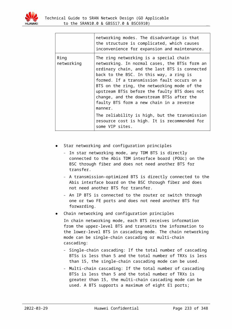
Technical Guide to SRAN Network Design (GO Applicable to the SRAN10.0 & GBSS17.0 & BSC6910)
CONFIDENTIAL
If you configure data for primary-homed BTSs and then use the configuration synchronization function to generate the configuration data for secondary-homed BTSs, ALM-21829 BSC Node Redundancy Configuration Exception is reported because a periodic synchronization task is executed on the CME on a daily basis. It is recommended that you configure data for primary-homed BTSs and then use immediate synchronization to generate the configuration data for secondary-homed BTSs.
If the configuration synchronization parameters include BSCIP, configuration synchronization cannot be implemented by running the ADD BTSEXTOPIP command in the Abis Independent Transmission feature. In this situation, manually configure parameters on the peer BSC.
The ADD PTPBVC command used to configure the Gb interface includes the NSEI parameter. Therefore, configuration synchronization cannot be implemented by running this command. In this situation, manually configure parameters on the peer BSC.
The MML commands listed in the following table support configuration synchronization, but the listed parameters do not support synchronization. To change the values of these parameters, manually configure the parameters on the peer BSC.
MML Command Parameter ID
ADD BTS BTSTYPE
SET BTSALM BTSTYPE
SET BTSAUTOPLANCFG BTSTYPE
ADD BTS SEPERATEMODE
ADD BTS RFUCFGBYSLOT
ADD BTS SRANMODE
ADD BTSCABINET SRANMODE
All boards on the backup BSC must be normal. The XPU/SPU that accommodates the main control AICP module of the backup BSC must be normal. Otherwise, node redundancy is unavailable because links cannot be synchronized.
In node redundancy scenarios, the main control AICP module is used for managing heartbeat links of the primary and secondary BSCs.
To query the number of the XPU/SPU where the main control AICP module resides, run the DSP FAMDATA command with Data Table set to CCENTRALTRAFFICCPU.In the command output, TrafficSubrackNo, TrafficSlotNo, and TrafficCpuNo corresponding to TrafficType equal to 3 indicate the XPU/SPU's CPU where the main control AICP module resides. As shown in the following figure, the main control AICP module is located on CPU 2 of the board in slot 0 of subrack 0.
2023-04-22 Huawei Confidential Page 233 of 258

Technical Guide to SRAN Network Design (GO Applicable to the SRAN10.0 & GBSS17.0 & BSC6910)
CONFIDENTIAL
Fault detection is implemented between two BSCs in a redundancy group by checking the heartbeat messages periodically transmitted from the peer end over the inter-BSC interface. The BEATSENDINGDISparameter specifies the interval for sending heartbeat messages between two BSCs.Heartbeat messages are transmitted over SCTP links on the inter-BSC interface. To check the status of an SCTP link, run the DSP SCTPLNK command.
22.4.3 Networking Design
The BSC Node Redundancy feature is used in two typical scenarios: load sharing mode and active/standby mode.
The two scenarios have been described in the BSC Node Redundancy Feature Parameter Description.
For details, see section "Network Topologies" in the BSC Node Redundancy Feature Parameter Description in GBSS17.0.
22.4.4 Capacity Planning
Capacity planning can be performed in terms of control plane, user plane, and transmission.
The control-plane capacity planning includes BHCA, number of cells, number of activated subscribers, and number of subscribers who are processing services.
The user-plane capacity planning includes CS traffic volume (Erlang), PS throughput, number of cells, and number of activated subscribers.
The transmission-plane capacity planning includes CS traffic volume (Erlang), number of BTSs, number of subscribers who are processing services, and number of call connections.
The capacity planning for the BSCs in a redundancy group is the same as that for an independent BSC. Each BSC in a redundancy group is configured with a specified number of boards that can meet the total specifications of two BSCs.
As shown in the following figure, one BSC reserves certain capacity for the other BSC in a redundancy group. The number of purchased boards for each BSC in a redundancy group can meet the total specifications of two BSCs. For example, if the BSCa supports 3000 TRXs and the BSCb supports 1000 TRXs, the XPU of each BSC supports 4000 TRXs. This rule also applies to other boards.
2023-04-22 Huawei Confidential Page 234 of 258

Technical Guide to SRAN Network Design (GO Applicable to the SRAN10.0 & GBSS17.0 & BSC6910)
CONFIDENTIAL
As shown in the following figure, the BSCs support dual-homed BTSs. Therefore, some BTSs serving VIP subscribers can be configured as dual-homed BTSs and required service processing boards are purchased for the BSCs. The remaining BTSs are configured as single-homed BTSs. After a BSC is faulty, services of the BTSs serving VIP subscribers can recover, but services of the remaining BTSs are interrupted. For example, the BSCa supports 3000 TRXs of which 1000 TRXs are configured for dual-homed BTSs; the BSCb supports 1000 TRXs of which 500 TRXs are configured for dual-homed BTSs. In this situation, the XPU of the BSCa can support 3500 TRXs and that of the BSCb can support 2000 TRXs. This rule also applies to other boards.
If the active BSC has been configured with the SAU, NIU, NASP, or GCG, the standby BSC must also be configured with the same board to ensure that related functions and features can recover after services on the standby BSCs are recovered.
The inter-BSC detection link interface used in the BSC Node Redundancy feature is a Huawei-customized interface which carries necessary equipment information for inter-BSC interaction, such as heartbeat messages. When the inter-BSC SCTP detection link is configured, the inter-BSC interface can only use IP transmission. Therefore, an IP interface board is required or the existing IP interface board is used.
The GOUc or GOUe on the BSC6900 can carry the inter-BSC detection link interface.
The traffic on the inter-BSC detection link can be neglected. Therefore, capacity planning is not required for the traffic.
22.4.5 Interface Design
The following table describes the requirements for transmission modes used by different interfaces during the implementation of BSC Node Redundancy.
2023-04-22 Huawei Confidential Page 235 of 258
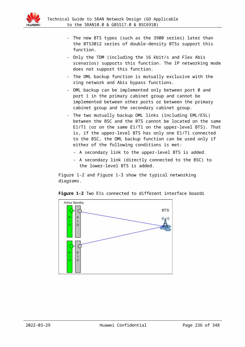
Technical Guide to SRAN Network Design (GO Applicable to the SRAN10.0 & GBSS17.0 & BSC6910)
CONFIDENTIAL
A Interface Control Plane
A Interface User Plane
Abis Interface Support BSC Node Redundancy
IP over ETH IP over ETH IP over ETH Manual switchover/automatic switchover
IP over ETH IP over ETH (E1/T1 transmission terminated at the router)
Manual switchover/automatic switchover
IP over ETH IP over ETH (the BTS directly connected to the BSC)
Manual switchover
TDM TDM TDM Not support
For details about transmission modes used by different interfaces, see section "Network Topologies."
2023-04-22 Huawei Confidential Page 236 of 258
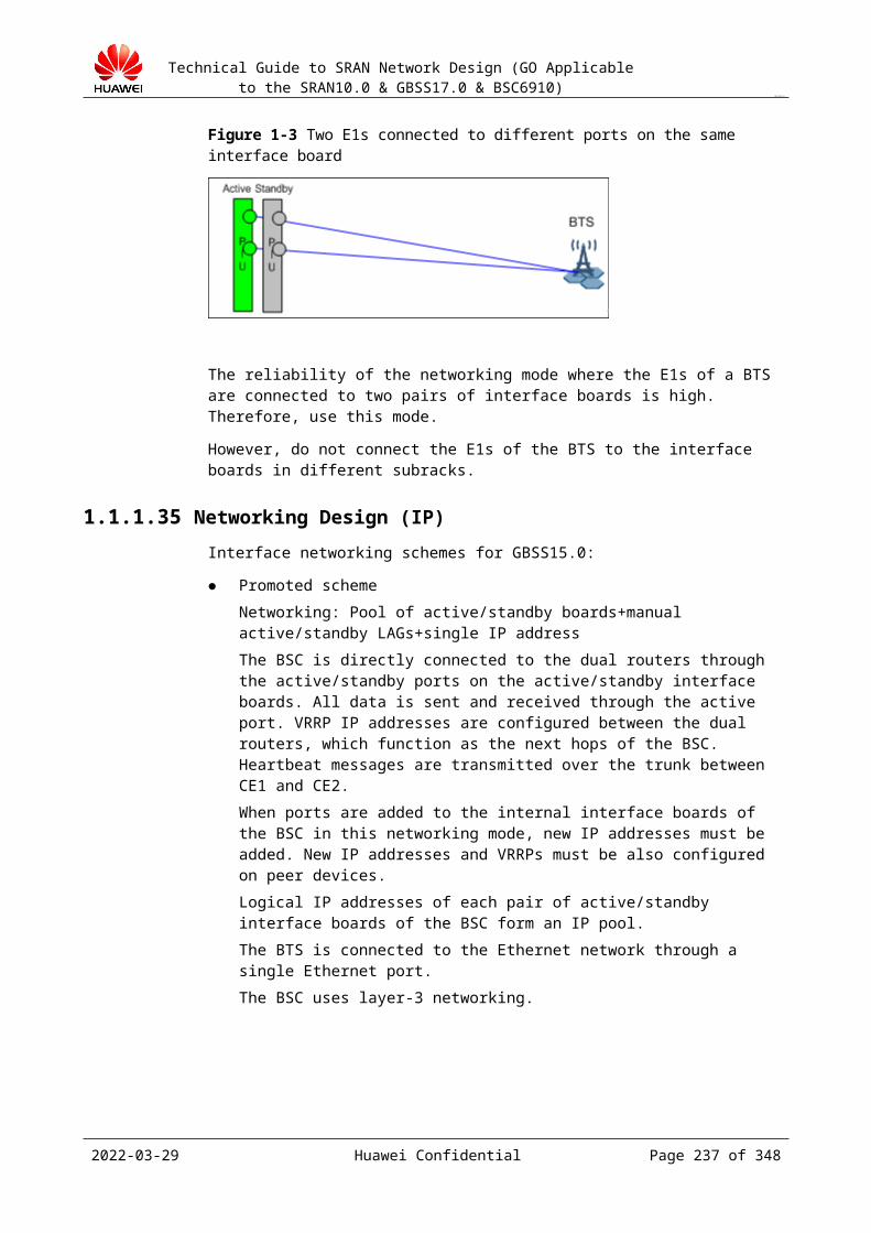
Technical Guide to SRAN Network Design (GO Applicable to the SRAN10.0 & GBSS17.0 & BSC6910)
CONFIDENTIAL
According to the GSM 03.71, Figure 22-1 shows the logical structure of the LCS system on the GSM network.
Figure 22-1 Logical structure of the LCS system on the GSM network
LMUType A CBC SMLC SMLC
MSC/VLRGMLC
SGSN
GMLC
LMUType B
BTS(LMUType B)
BSC
MS
HLR
gsmSCF
ExternalLCS client
Other PLMN
Lp
LsLb
CBC-SMLC
CB
C-B
SCUm
Abis
Abis
A
Gb Gs
Lg
Lg
Lh
Lc
Le
Table 22-1 NEs involved in the LCS service
NE Function Description
LCS Client The LCS client is a logical function entity that requests location information of one or multiple MSs from the LCS server. The location request message contains the QoS parameter. The LCS client can reside in entities on the PLMN (including MSs) or entities out of the PLMN.
MS The LCS server can provide location information for an MS. For the network-based LCS, a destination MS does not need to support the LCS. For an MS-assistant or MS-based LCS, an MS needs to support the LCS. For all LCSs, the MS privacy can be controlled through registration in each location request. On the LCS client, a destination MS can be identified using MSISDN. On the PLMN network, a destination MS can be identified using MSISDN, IMSI, or an internal flag of the PLMN network. In emergency calls, a destination MS can be identified using MSISDN, IMSI, or NA-ESRK+IMEI.
2023-04-22 Huawei Confidential Page 237 of 258
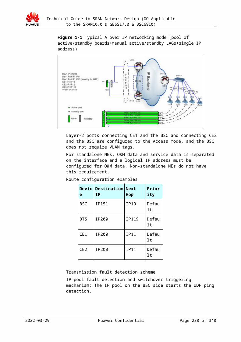
Technical Guide to SRAN Network Design (GO Applicable to the SRAN10.0 & GBSS17.0 & BSC6910)
CONFIDENTIAL
NE Function Description
SMLC The serving mobile location center (SMLC) coordinates and schedules resources required for the LCS and calculates location estimation results and precision.Two SMLCs are available: NSS-based SMLC and BSS-based SMLC. The NSS-based SMLC interworks with one or multiple MSC servers over the Ls interface to support the LCS and manage the LMU. The BSS-based SMLC interworks with one or multiple BSCs over the Lb interface to support the LCS and manage the LMU. Both NSS-based SMLC and BSS-based SMLC can obtain resources and information of other SMLCs over the Lp interface. The SMLC and the gateway mobile location center (GMLC) can be integrated into one physical node or can reside in different physical nodes. When the CBC connects to the BSC, the SMLC needs to interwork with the CBC to perform assistance data broadcast using the cell broadcast function of an existing cell.
GMLC One PLMN network can have multiple GMLCs. The GMLC is the first node through which an external LCS client accesses the GSM network. After the GMLC receives an LCS request from an LCS subscriber, it queries route information of a destination MS from the HLR over the Lh interface. After the GLMC authenticates an LCS subscriber, it sends the LCS request to the VMSC over the Lg interface. After the LCS flow ends, the GMLC obtains the location estimation result from the VMSC.
LMU The LMU is a logical network entity. Its LCS measurement function can support one or multiple LCS methods. The LMU measurement is classified into the following two measurements: LCS measurement for an MS: is used to calculate the location
estimation result of an MS. Assistance measurement for all MSs in a specific geographic
area: is used to perform periodic measurement over radio interfaces, such as Absolute Time Differences (ATD) and Real Time Differences (RTD).
Each LMU is controlled and managed by an SMLC on the network. Measurement parameters and relevant commands of the LMU can be provided by this SMLC or preset in the LMU. All measurement results of the LMU are reported to the SMLC through an LCS request. The LMU is classified into the A-type and B-type LMUs: The A-type LMU is identified with the IMSI. It adopts the same
frequency with an MS and accesses the BTS over the Um interface. It does not connect to any NE. It has an independent subscription profile in the HLR and supports the mobility management function of all radio resources and interfaces. The HLR differentiates the A-type LMU and an MS based on settings in the subscription profile.
The B-type LMU accesses the BSC over the Abis interface. It can be deployed independently or be integrated into the BTS.
2023-04-22 Huawei Confidential Page 238 of 258

Technical Guide to SRAN Network Design (GO Applicable to the SRAN10.0 & GBSS17.0 & BSC6910)
CONFIDENTIAL
NE Function Description
MSC/VLR The MSC/VLR registers and authenticates an MS and manages LCS requests relevant or irrelevant to GSM calls. The MSC server accesses the GMLC over the Lg interface and the SMLC over the Ls interface. If the MSC server connects to the SGSN over the Gs interface, the MSC server checks whether an MS is in the GPRS attach status to determine whether it pages the MS over the A interface or the Gs interface.
SGSN The SGSN transfers paging requests in the CS domain received over the Gs interface to the BSS.
BSC The BSC connects to the SMLC over the Lb interface. It provides system operation capability and LCS assistance function in the LCS flow.
HLR The HLR stores LCS subscription data and route information of an MS. It connects to the GMLC over the Lh interface. For a roaming MS, the HLR serving the MS and the SMLC may reside in different PLMN networks.
CBC The CBC connects to or is embedded the broadcast entity of the BSC. It broadcasts LCS assistance information specified by the SMLC to cells managed by the BSC using the signaling between the CBC and the SMLC.
gsmSCF The gsmSCF connects to the GMLC over the Lc interface and can visit the LCS using the CAMEL III.
Huawei BSC supports the LCS service only in the CELL+TA mode. It supports NSS-based SMLC and BSS-based SMLC and does not support the LMU. 22.5.1 Figure 22-2 shows the logical structure of the NSS-based SMLC. 22.5.1 Figure 22-3 shows the logical structure of the BSS-based SMLC. In this scenario, Huawei BSC and the SMLC are integrated.
Figure 22-2 Logical structure of the NSS-based SMLC
Figure 22-3 Logical structure of the BSS-based SMLC
2023-04-22 Huawei Confidential Page 239 of 258
Technical Guide to SRAN Network Design (GO Applicable to the SRAN10.0 & GBSS17.0 & BSC6910)
CONFIDENTIAL
Figure 22-4 shows the LCS flow initiated by an external LCS client.
Figure 22-4 LCS flow initiated by an external LCS client
For the A interface in the LCS design, configure the LCS function data on the BSC and longitude and latitude information of each cell.
22.5 LCS Function DesignThe location service (LCS) is a special service specific to the GSM network. The precision of the LCS service implemented on the GSM network is low, but can meet the requirements of
2023-04-22 Huawei Confidential Page 240 of 258
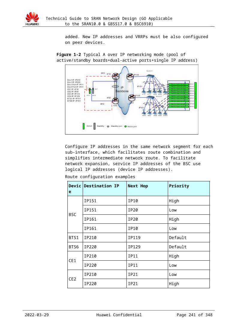
Technical Guide to SRAN Network Design (GO Applicable to the SRAN10.0 & GBSS17.0 & BSC6910)
CONFIDENTIAL
those services requiring low precision. The LCS service provides MSs with the weather report, tour arrangement, emergency aid, and traffic conditions based on the location of MSs.
According to the GSM 03.71, Figure 22-1 shows the logical structure of the LCS system on the GSM network.
Figure 22-1 Logical structure of the LCS system on the GSM network
LMUType A CBC SMLC SMLC
MSC/VLRGMLC
SGSN
GMLC
LMUType B
BTS(LMUType B)
BSC
MS
HLR
gsmSCF
ExternalLCS client
Other PLMN
Lp
LsLb
CBC-SMLC
CB
C-B
SCUm
Abis
Abis
A
Gb Gs
Lg
Lg
Lh
Lc
Le
Table 22-1 NEs involved in the LCS serviceNE Function Description
LCS Client The LCS client is a logical function entity that requests location information of one or multiple MSs from the LCS server. The location request message contains the QoS parameter. The LCS client can reside in entities on the PLMN (including MSs) or entities out of the PLMN.
MS The LCS server can provide location information for an MS. For the network-based LCS, a destination MS does not need to support the LCS. For an MS-assistant or MS-based LCS, an MS needs to support the LCS. For all LCSs, the MS privacy can be controlled through registration in each location request. On the LCS client, a destination MS can be identified using MSISDN. On the PLMN network, a destination MS can be identified using MSISDN, IMSI, or an internal flag of the PLMN network. In emergency calls, a destination MS can be identified using MSISDN, IMSI, or NA-ESRK+IMEI.
2023-04-22 Huawei Confidential Page 241 of 258

Technical Guide to SRAN Network Design (GO Applicable to the SRAN10.0 & GBSS17.0 & BSC6910)
CONFIDENTIAL
SMLC The serving mobile location center (SMLC) coordinates and schedules resources required for the LCS and calculates location estimation results and precision.Two SMLCs are available: NSS-based SMLC and BSS-based SMLC. The NSS-based SMLC interworks with one or multiple MSC servers over the Ls interface to support the LCS and manage the LMU. The BSS-based SMLC interworks with one or multiple BSCs over the Lb interface to support the LCS and manage the LMU. Both NSS-based SMLC and BSS-based SMLC can obtain resources and information of other SMLCs over the Lp interface. The SMLC and the gateway mobile location center (GMLC) can be integrated into one physical node or can reside in different physical nodes. When the CBC connects to the BSC, the SMLC needs to interwork with the CBC to perform assistance data broadcast using the cell broadcast function of an existing cell.
GMLC One PLMN network can have multiple GMLCs. The GMLC is the first node through which an external LCS client accesses the GSM network. After the GMLC receives an LCS request from an LCS subscriber, it queries route information of a destination MS from the HLR over the Lh interface. After the GLMC authenticates an LCS subscriber, it sends the LCS request to the VMSC over the Lg interface. After the LCS flow ends, the GMLC obtains the location estimation result from the VMSC.
LMU The LMU is a logical network entity. Its LCS measurement function can support one or multiple LCS methods. The LMU measurement is classified into the following two measurements: LCS measurement for an MS: is used to calculate the location estimation
result of an MS. Assistance measurement for all MSs in a specific geographic area: is
used to perform periodic measurement over radio interfaces, such as Absolute Time Differences (ATD) and Real Time Differences (RTD).
Each LMU is controlled and managed by an SMLC on the network. Measurement parameters and relevant commands of the LMU can be provided by this SMLC or preset in the LMU. All measurement results of the LMU are reported to the SMLC through an LCS request. The LMU is classified into the A-type and B-type LMUs: The A-type LMU is identified with the IMSI. It adopts the same
frequency with an MS and accesses the BTS over the Um interface. It does not connect to any NE. It has an independent subscription profile in the HLR and supports the mobility management function of all radio resources and interfaces. The HLR differentiates the A-type LMU and an MS based on settings in the subscription profile.
The B-type LMU accesses the BSC over the Abis interface. It can be deployed independently or be integrated into the BTS.
MSC/VLR The MSC/VLR registers and authenticates an MS and manages LCS requests relevant or irrelevant to GSM calls. The MSC server accesses the GMLC over the Lg interface and the SMLC over the Ls interface. If the MSC server connects to the SGSN over the Gs interface, the MSC server checks whether an MS is in the GPRS attach status to determine whether it pages the MS over the A interface or the Gs interface.
2023-04-22 Huawei Confidential Page 242 of 258
Technical Guide to SRAN Network Design (GO Applicable to the SRAN10.0 & GBSS17.0 & BSC6910)
CONFIDENTIAL
SGSN The SGSN transfers paging requests in the CS domain received over the Gs interface to the BSS.
BSC The BSC connects to the SMLC over the Lb interface. It provides system operation capability and LCS assistance function in the LCS flow.
HLR The HLR stores LCS subscription data and route information of an MS. It connects to the GMLC over the Lh interface. For a roaming MS, the HLR serving the MS and the SMLC may reside in different PLMN networks.
CBC The CBC connects to or is embedded the broadcast entity of the BSC. It broadcasts LCS assistance information specified by the SMLC to cells managed by the BSC using the signaling between the CBC and the SMLC.
gsmSCF The gsmSCF connects to the GMLC over the Lc interface and can visit the LCS using the CAMEL III.
Huawei BSC supports the LCS service only in the CELL+TA mode. It supports NSS-based SMLC and BSS-based SMLC and does not support the LMU. Figure 22-2 shows the logical structure of the NSS-based SMLC. Figure 22-3 shows the logical structure of the BSS-based SMLC. In this scenario, Huawei BSC and the SMLC are integrated.
Figure 22-2 Logical structure of the NSS-based SMLC
Figure 22-3 Logical structure of the BSS-based SMLC
Figure 22-4 shows the LCS flow initiated by an external LCS client.
2023-04-22 Huawei Confidential Page 243 of 258
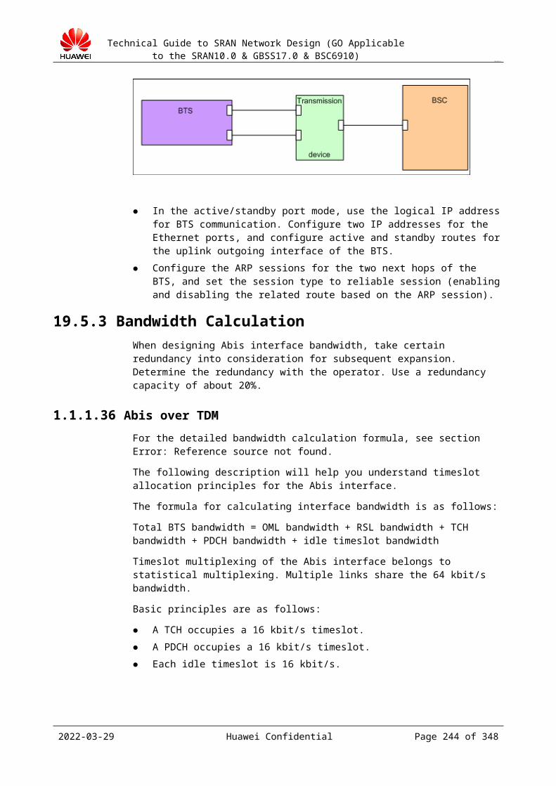
Technical Guide to SRAN Network Design (GO Applicable to the SRAN10.0 & GBSS17.0 & BSC6910)
CONFIDENTIAL
Figure 22-4 LCS flow initiated by an external LCS client
For the A interface in the LCS design, configure the LCS function data on the BSC and longitude and latitude information of each cell.
2023-04-22 Huawei Confidential Page 244 of 258
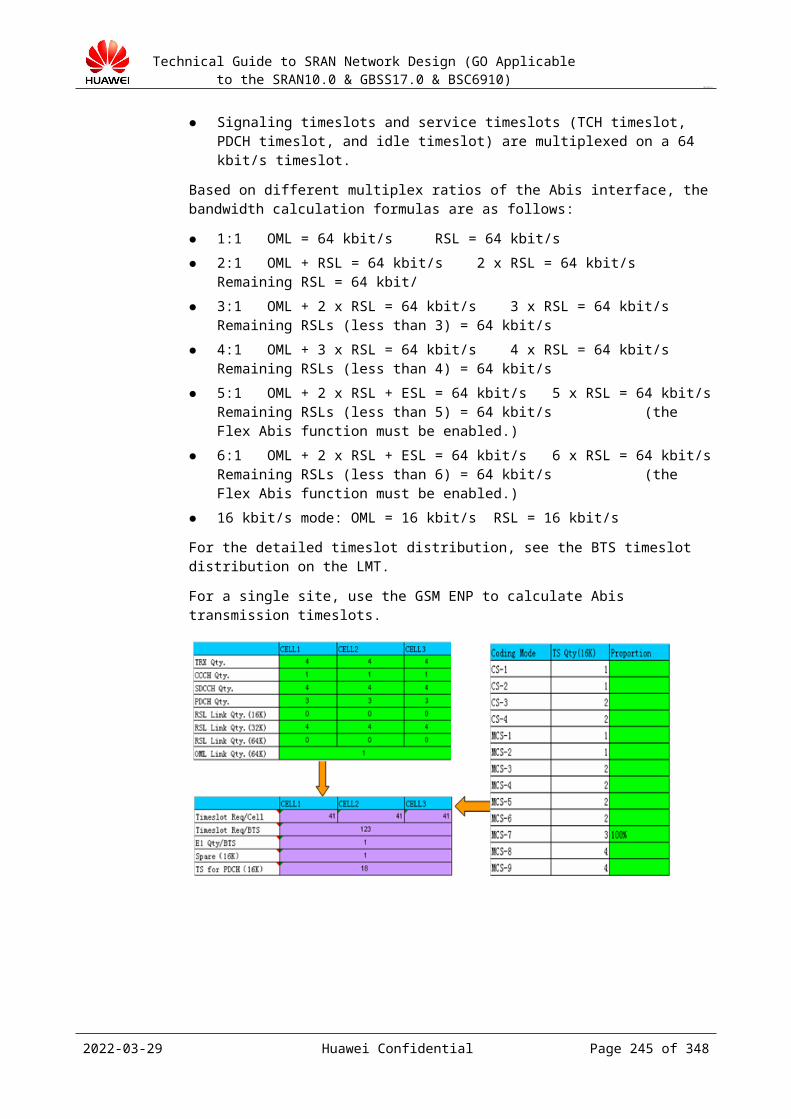
Technical Guide to SRAN Network Design (GO Applicable to the SRAN10.0 & GBSS17.0 & BSC6910)
CONFIDENTIAL
23 BTS Design
23.1 BTS Cable Design23.1.1 Purpose of the Design
Design the internal cable diagram of the BTS in different BSC types and configurations to
provide guidance for engineers in construction and improve work efficiency.
23.1.2 Input of the DesignNetwork plan data of a cell (BTS type, carrier quantity, SXXX, and frequency)
23.2 Design Tool of the BTS Cable DiagramCurrently, tools are available for the cable connection design for major BTS types. Onsite TSD personnel can obtain the tool at http://support.huawei.com.
23.3 BTS Transmission Design23.3.1 Purpose of the Design
For the Huawei's third and fourth generation of BTSs with the most installed base in the market, design BTS transmission networking methods under different transmission conditions to provide guidance for engineers in construction and improve work efficiency.
23.3.2 BTS TransmissionHuawei's third and fourth generation of BTSs support the TDM and IP over FE/GE. The carrier quantity supported by different transmission protocols varies. The TDM supports a maximum of 126 carriers and the IP over FE supports a maximum of 60 carriers.
For details about networking, see section 19.5 "Abis Interface Design."
2023-04-22 Huawei Confidential Page 245 of 258

Technical Guide to SRAN Network Design (GO Applicable to the SRAN10.0 & GBSS17.0 & BSC6910)
CONFIDENTIAL
Constraints on usage of different transmission media (E1 and FE): Currently, transmission interface boards of GSM BTSs are DTMU and GTMU. The DTMU does not support hybrid usage of E1 and FE interfaces.
BTS Type
Transmission Board
Supported Transmission Mode
Supported Transmission Interface
Hybrid Usage of Transmission Interface Supported?
BTS3012 DTMU, DPTU TDM, IP over FE E1/T1, FE No
BTS3012AE
DTMU, DPTU TDM, IP over FE E1/T1, FE No
BTS3006C DMCM TDM E1/T1, STM-1 N/A
BTS3900 GTMU, UIEB, UTRPC
TDM, IP over FE/GE E1/T1, FE/GE Hybrid usage of TDM and IP is not supported.
BTS3900E MICRO TDM, IP over FE E1/T1, FE No
BTS3900L GTMU, UIEB, UTRPC
TDM, IP over FE/GE E1/T1, FE/GE Hybrid usage of TDM and IP is not supported.
BTS3900B PICO IP over FE FE N/A
BTS3900A GTMU, UIEB, UTRPC
TDM, IP over FE/GE E1/T1, FE/GE Hybrid usage of TDM and IP is not supported.
BTS3900AL
GTMU, UIEB, UTRPC
TDM, IP over FE/GE E1/T1, FE/GE Hybrid usage of TDM and IP is not supported.
2023-04-22 Huawei Confidential Page 246 of 258
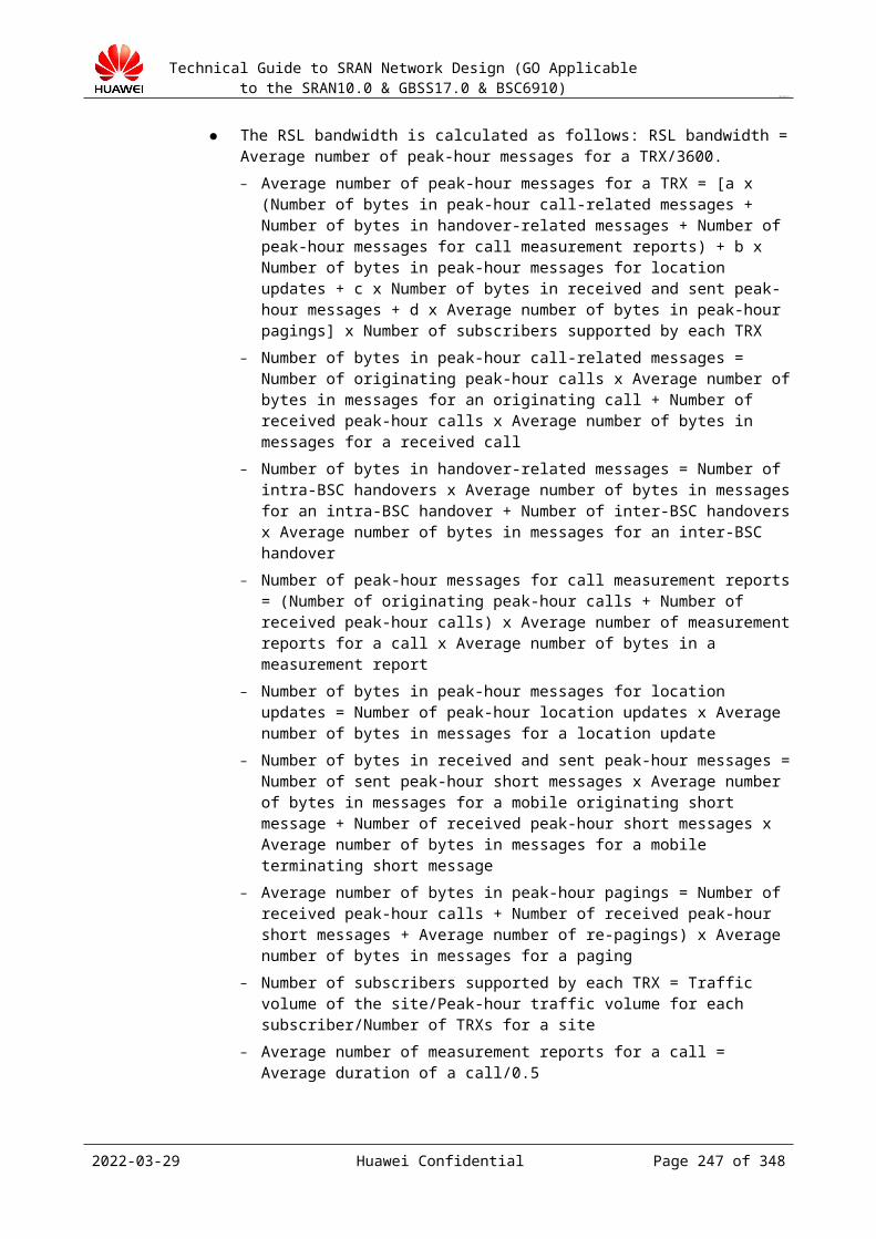
Technical Guide to SRAN Network Design (GO Applicable to the SRAN10.0 & GBSS17.0 & BSC6910)
CONFIDENTIAL
DBS3900 GTMU, UIEB, UTRPC
TDM, IP over FE/GE E1/T1, FE/GE Hybrid usage of TDM and IP is not supported.
The BTS communicates with the BSC either in the port IP communication mode or in the logical IP communication mode. The logical IP communication in GBSS14.0 is the same as that in GBSS9.0. If the BTS adopts the port IP communication mode, only configurations of port 0 are supported in GBSS9.0 and configurations of the FE optical interface are added to support the GU transmission backup scenario in GBSS12.0 and later versions. The following table describes comparison of two versions.
Comparison of GBSS9.0 and GBSS12.0 and later versions when the BTS adopts the port IP communication mode
Configuration of the Port IP Communication Mode
GBSS9.0 GBSS12.0 and Later Version
FE0 configured FE1 not configured
Support Support
FE0 configured FE1 configured Not support Support
FE0 not configured
FE1 configured Not support Support
NOTEIf BTSIP configured on the BSC side is the same as the device IP address of any port configured on the BTS, the BTS adopts the port IP communication mode. If BTSIP differs from the device IP configured on the BTS, the BTS adopts the logical IP communication mode.When the BTS adopts the port IP communication mode and only the electrical interface is used, the IP address needs to be configured on port 0. That is, BTSIP needs to be the same as the device IP address of Ethernet port 0.When the BTS adopts the port IP communication mode and only the optical interface is used, the IP address needs to be configured on port 1. That is, BTSIP needs to be the same as the device IP address of Ethernet port 1.In an upgrade of an installed site, VLAN tags can be added based on the service type. For new sites, except for the GTMUa board, add VLAN tags based on the IP address of the next hop.
The BSC communicates with the BTS either in the port IP communication mode or in the logical IP communication mode. The following table shows advantages and disadvantages of these two communication modes. For details about configuration methods, see the deployment guide of the BSC6910.
Advantages and disadvantages of the port IP communication mode and the logical IP communication mode
2023-04-22 Huawei Confidential Page 247 of 258

Technical Guide to SRAN Network Design (GO Applicable to the SRAN10.0 & GBSS17.0 & BSC6910)
CONFIDENTIAL
Advantage/Disadvantage
Port IP Communication Mode
Logical IP Communication Mode
Advantage The configuration is simple.
Port addresses of intermediate transmission networks are visible.
Logical IP addresses are used as service IP addresses, which requires less IP addresses.
When physical links are faulty, cooperation of links is easy to be implemented to ensure that services are not affected.
Disadvantage When physical links are faulty, cooperation of links is difficult to be implemented to ensure that services are not affected.
Port IP addresses are used as service IP addresses, which requires more IP addresses.
Static routes to logical IP addresses need to be configured.
When intermediate layer-3 transmission devices are available, routes of this logical IP address need to be identified, which has high requirements on transmission networks.
23.3.3 eGBTS NetworkingThe eGBTS is introduced in the GBSS15.0. Compared with the transmission GBTS, 3900 series base stations support the eGBTS and matching BTS types are DBS3900 eGSM, BTS3900 eGSM, BTS3900A eGSM, BTS3900L eGSM, and BTS3900AL eGSM.
The eGBTS has the following characteristics:
The BTS provides the southbound interface and OM channels. The M2000/CME can directly manage the eGBTS.
The BTS LMT maintains and manages local and remote eGBTSs. The original Abis interface is adjusted to the Abis 2.0 interface. The original OML
changes to CSL and the message flow also changes. The layer-2 LAPD over the original Abis interface changes to the SCTP, which is the
same as that of the UMTS. The BTS license file is added and the file is directly loaded on the BTS. The BSC supports the hybrid networking of non-eGBTS and GBTS, but does not
support hybrid cascading.
2023-04-22 Huawei Confidential Page 248 of 258
Technical Guide to SRAN Network Design (GO Applicable to the SRAN10.0 & GBSS17.0 & BSC6910)
CONFIDENTIAL
Figure 23-1 Networking topology change of the eGBTS
Figure 23-2 Change of northbound and southbound interfaces of the eGBTS
2023-04-22 Huawei Confidential Page 249 of 258

Technical Guide to SRAN Network Design (GO Applicable to the SRAN10.0 & GBSS17.0 & BSC6910)
CONFIDENTIAL
24 OM Networking Design
24.1 Design Overview24.1.1 Input of the Design
Physical position of the MSC, BSC, and PCU and the topology Number of BTSs
24.1.2 Design Content Networking of the BSS and the NMS Calculation of NMS bandwidth
24.1.3 ReferenceM2000 Commissioning Guide
24.2 Introduction to OMU24.2.1 Standalone OMU
The ETH5-SCU6 and ETH4-SCU7 are network cards for internal communication. The OMU connects to the SCU using the cards to obtain the performance and alarm information of the BSC board.
The ETH0 and ETH1 are network cards for external communication, connecting to the LMT through the LAN switch or hub.
Download the BSC GOMU Management Guide at http://support.huawei.com.
2023-04-22 Huawei Confidential Page 250 of 258
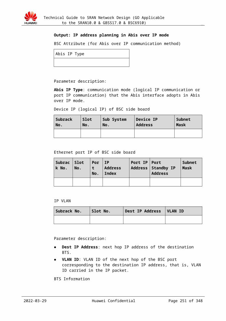
Technical Guide to SRAN Network Design (GO Applicable to the SRAN10.0 & GBSS17.0 & BSC6910)
CONFIDENTIAL
Figure 24-1 Standalone OMU
24.2.2 Dual OMUThe ETH5-SCU6 and ETH4-SCU7 are network cards for internal communication. The OMU connects to the SCU using the cards to obtain the performance and alarm information of the BSC board.
The ETH3-UPDATE is a network card used to connect two OMUs working in active/standby mode, to implement data synchronization and software update.
The ETH0 and ETH1 are network cards for external communication, connecting to the LMT through the LAN switch or hub.
The active and standby OMUs are configured with the same IP address.
The active and standby OMUs connect four LAN cables to the hub or LAN switch.
Download the BSC GOMU Management Guide at http://support.huawei.com.
2023-04-22 Huawei Confidential Page 251 of 258
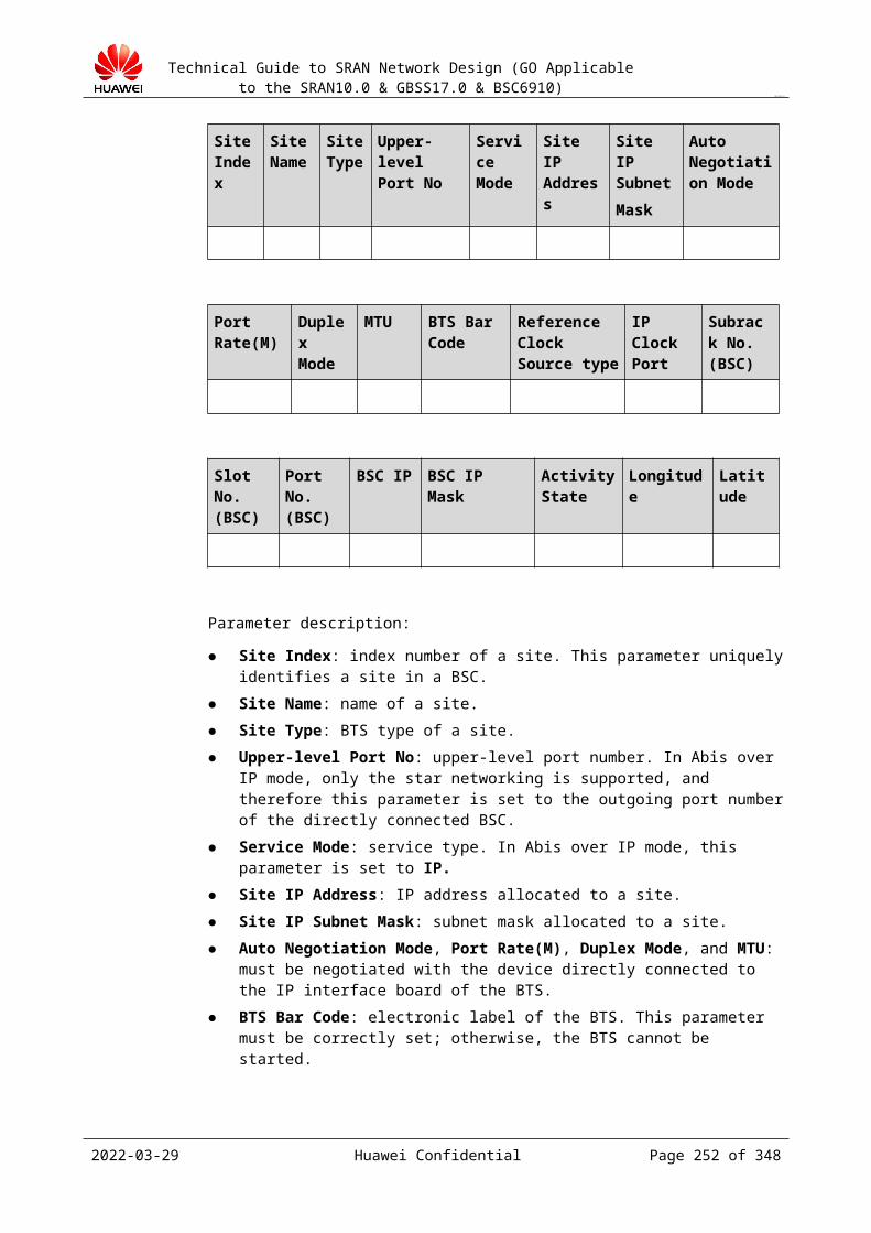
Technical Guide to SRAN Network Design (GO Applicable to the SRAN10.0 & GBSS17.0 & BSC6910)
CONFIDENTIAL
Figure 24-1 Dual OMUs
24.3 OM Networking DesignIf the network of a customer is IP-based, use the IP networking.
If the existing network is TDM-based, entire E1 networking is preferred.
If the existing network is TDM-based and the customer has high requirements on cost, networking for part of E1 timeslots is recommended. That is, some of timeslots of the E1 link are used as operation and maintenance channels.
24.3.1 Networking for Part of E1/T1 TimeslotsIn this mode, the following devices are required: router, MSC, and Mercury3600.
The core of networking for part of E1 timeslots is as follows: Cross-connect the NMS information to the idle timeslots of the existing E1 link by using the Mercury3600 for transmitting the information to the peer end. The peer end cross-connects the NMS information and provides the information to the NMS by using a router.
The timeslot extraction principle (specific to Mercury3600) is as follows:
2023-04-22 Huawei Confidential Page 252 of 258

Technical Guide to SRAN Network Design (GO Applicable to the SRAN10.0 & GBSS17.0 & BSC6910)
CONFIDENTIAL
In the networking mode of part of E1 timeslots, timeslot cross-connect devices, such as Mercury3600 are used. The four universal slots of a Mercury3600 can be inserted with 4-E1 interface cards and 2-V35 interface cards. A maximum of 16 E1 channels can be provided. Cross connection of any timeslot can be performed on any two ports. Any port can use the near loop or remote loop to implement performance monitor and system maintenance.
In the current OM networking, Mercury3600 uses a 4-E1 interface card (with 25-pin D model).
Figure 24-1 shows the pins.
Figure 24-1 25-pin D model interface
For details, see the Mercury 3600 Manual.
Figure 24-2 shows a typical OM networking.
2023-04-22 Huawei Confidential Page 253 of 258
Technical Guide to SRAN Network Design (GO Applicable to the SRAN10.0 & GBSS17.0 & BSC6910)
CONFIDENTIAL
Figure 24-2 Networking for part of E1/T1 timeslots
24.3.2 Entire E1/T1 NetworkingCompared with networking for part of E1 timeslots, entire E1 networking does not require cross-connect devices for timeslot extraction and exchange. An entire 2 Mbit/s E1 link can be used for information transmission, applicable to a network requiring abundant transmission resources and large data volume.
In this mode, routers and MSCs are required.
Figure 24-1 shows a typical OM networking.
Figure 24-1 Entire E1/T1 Networking
2023-04-22 Huawei Confidential Page 254 of 258
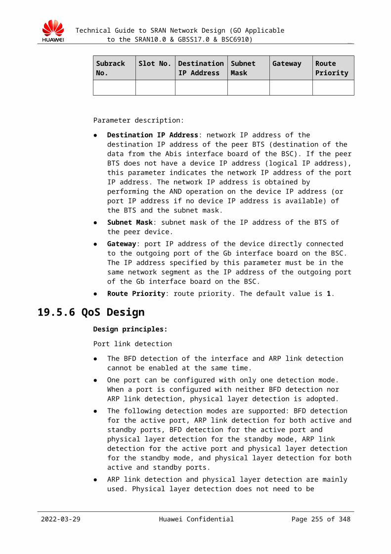
Technical Guide to SRAN Network Design (GO Applicable to the SRAN10.0 & GBSS17.0 & BSC6910)
CONFIDENTIAL
24.3.3 IP NetworkingUsually, IP networking is used in the private network of an operator. With high reliability and high transmission efficiency, this networking mode is preferred in the area where the operator has constructed a private IP network. In an IP network, the NMS device only needs to provide a network interface because the routes of the IP network and remote end are completed. The bandwidth for IP networking is allocated by the operator as required. A private IP network requires private transmission resource. Therefore, cost is high.
Figure 24-1 and Figure 24-2 show typical OM networking.
Figure 24-1 OM network topology
Figure 24-2 IP networking in dual OMU mode
In dual OMU mode, three IP addresses need to be planned. Each OMU is configured with a physical IP address. Two OMUs share a logical IP address. The three IP addresses are in the same network segment.
2023-04-22 Huawei Confidential Page 255 of 258
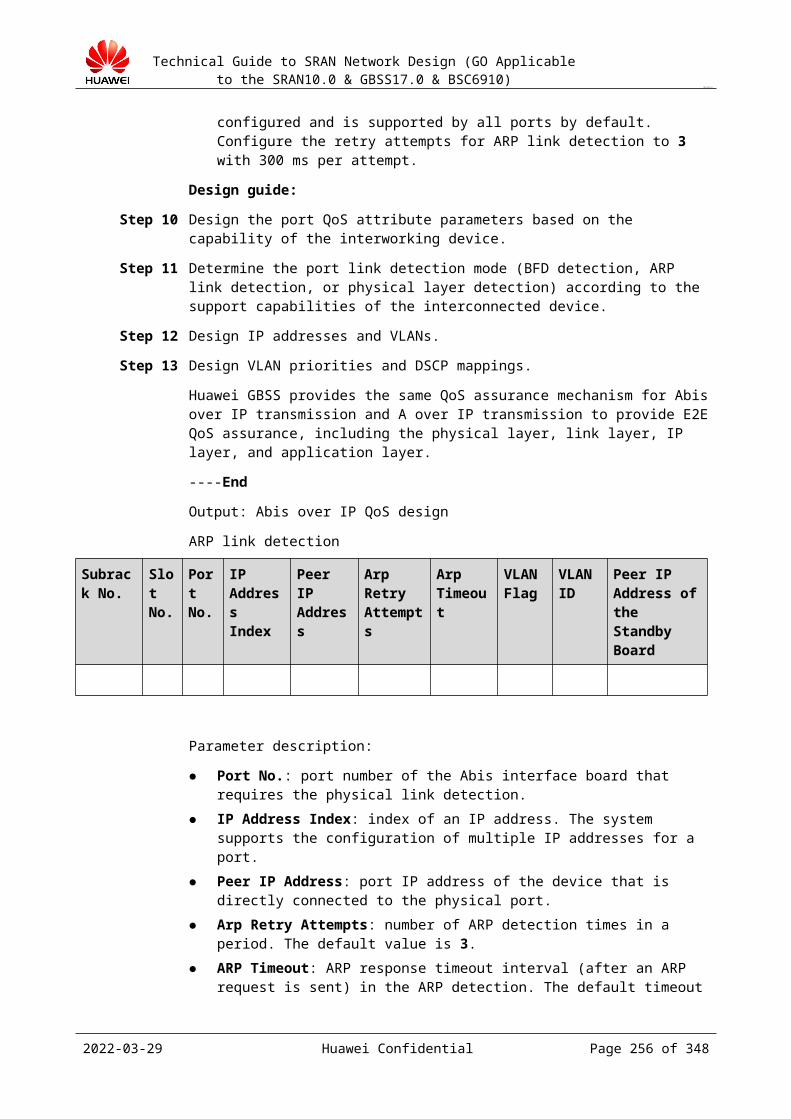
Technical Guide to SRAN Network Design (GO Applicable to the SRAN10.0 & GBSS17.0 & BSC6910)
CONFIDENTIAL
Preferentially, switch is performed on ports of the same board.
24.3.4 Networking InstancesFigure 24-1 and Figure 24-2 show an office adopting E1 networking.
Figure 24-1 OM E1 networking instance 1
To facilitate M2000 maintenance, three M2000s are placed in an equipment room. The BSCs in other cities are remotely connected to this equipment room. E1 transmission is used. Mercury3600s in this networking provide port conversion and timeslot adjustment functions.
2023-04-22 Huawei Confidential Page 256 of 258
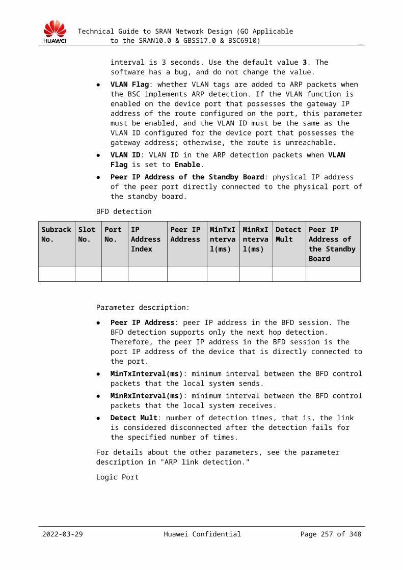
Technical Guide to SRAN Network Design (GO Applicable to the SRAN10.0 & GBSS17.0 & BSC6910)
CONFIDENTIAL
Figure 24-2 OM E1 networking instance 2
24.4 OM IP Address PlanningNegotiate with operators how to plan IP addresses.
When planning IP addresses, pay attention to the following:
Ensure the IP addresses of the LANs connected to a WAN in different network segments. Ensure the LAN port and the WAN port of a router in an office in different network
segments. Ensure the WAN ports of two routers connecting and communicating with each other in
different network segments. Ensure the WAN ports of routers with different office directions in different network
segments. Divide a large network segment into small subnets based on the subnet masks of IP
addresses and allocate the IP addresses of the subnets to LANs, to save IP network segment.
Assess the number of IP addresses that can be allocated and the extension space in future when allocating IP addresses of subnets.
24.5 Route PlanningThe network between the network card of extranet of the GOMU and the LMT/M2000 is defined as the extranet. The GOMU can connect to the LMT/M2000 directly or through multiple routers (gateways).
2023-04-22 Huawei Confidential Page 257 of 258
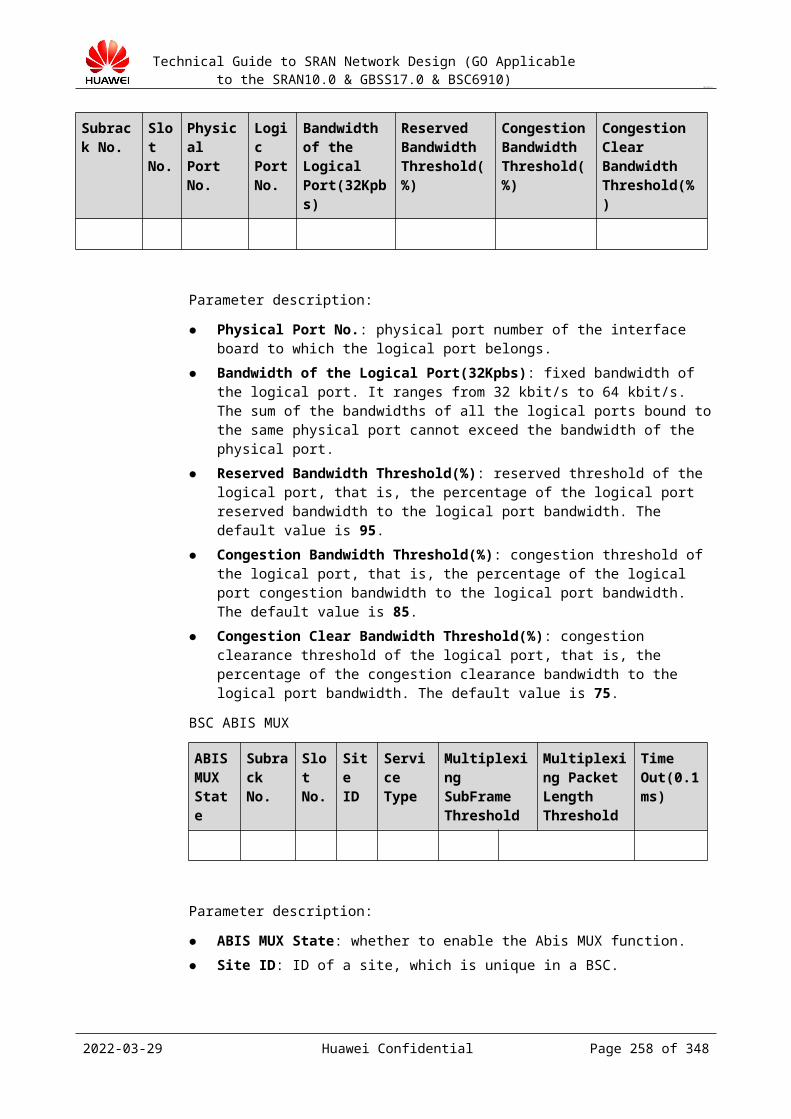
Technical Guide to SRAN Network Design (GO Applicable to the SRAN10.0 & GBSS17.0 & BSC6910)
CONFIDENTIAL
When the OMU communicates with the M2000 through routers (gateways), the OMU must connect to the master server and the slave server of the M2000. In this case, routs between the OMU and M2000 need to be added. Set the destination IP address of the OMU route to the network segment address of M2000 by running ADD OMUIPRT, rather than the IP address of the master server and the slave server of the M2000. If multiple the M2000 has multiple network segments, set the destination IP address to multiple network segment addresses. Ensure that when a slave server of the M2000 is added, a route to the newly added slave server of the M2000 is added on the OMU.
24.6 Impact of eGBTS on the O&MThe eGBTS is introduced in the GBSS15.0. Figure 24-1 shows the change of the OM structure.
Figure 24-1 Change of the OM structure
The OM model and function of the non-eGBTS are deployed on the BSC side. BTSs are managed by the BSC and access the OSS. BTSs do not have independent southbound interfaces. In the eGBTS, relevant models and functions of physical devices and transmissions of the BTS are adjusted from the BSC to the BTS. The BSC implements only the logical model and service processing. The OSS manages the OM of physical devices, transmission, and local logical objects of the BTS. The OM management channel and the southbound interface are added between the OSS and the eGBTS and are managed by the M2000 as the new NE type.
The BTS LMT is added for the eGBTS. Operation and maintenance can be performed on the local eGBTS or by remotely connecting to the eGBTS through the communication network.
The BSC6910 LMT is removed with the OM management function of public physical devices and transmission of the eGBTS. This OM management function is implemented by the M2000 and the BTS LMT currently.
For the eGBTS, a new NE type is added on the OSS northbound interface. The northbound model of this NE type differs from that of the non-eGBTS. On a hybrid network, a set of northbound interfaces are available and can be differentiated through the NE type.
The local maintenance tool SMT of the non-eGBTS is removed in the eGBTS and its function is migrated to the BTS LMT.
2023-04-22 Huawei Confidential Page 258 of 258