
TECHNICAL GUIDE - Forestry CommissionFILE/fctg001.pdf · Effects of friction on pulling forces 6...
30
TECHNICAL GUIDE Winching operations in forestry Tree takedown and vehicle debogging
Transcript of TECHNICAL GUIDE - Forestry CommissionFILE/fctg001.pdf · Effects of friction on pulling forces 6...
T E C H N I C A L G U I D E
Winching operations in forestryTree takedown and vehicle debogging

Winching operations in forestryTree takedown and vehicle debogging
Duncan Ireland
Technical Guide
Forestry Commission: Edinburgh

ii
© Crown Copyright 2004
First published in 2004 by the Forestry Commission231 Corstorphine Road, Edinburgh EH12 7AT.
Applications for reproduction of any part of this Practice Guide should be addressed to:HMSO, Licensing Division, St Clements House, 2–16 Colegate, Norwich NR3 1BQ.
ISBN 0 85538 638 X
IRELAND, D. (2004).Winching operations in forestry Tree takedown and vehicle deboggingForestry Commission Technical Guide.Forestry Commission, Edinburgh. i–iv + 1–24 pp.
Keywords: fail-safe systems, forces in systems, forestry training, tree takedown, winching operations, woodlandmanagement, vehicle debogging.
Printed in the United Kingdomon Robert Horne Hello Matt
FCTG001/FG(KMA)/BTH-1000/SEP04
Enquiries relating to this publication should be addressed to:
Forestry CommissionTechnical DevelopmentForest Management DivisionAe VillageDumfries DG1 1QB
Tel: 01387 860264Fax: 01387 860386
Acknowledgements
The author would like to thank the following for their support and advice throughout the production of this report:
Forestry Commission Training Services; Forestry Commission Mechanical Engineering Services; Health and Safety
Executive; WM Clark and Son (Parkgate) Ltd; Jim Riddle.

iii
Introduction 1
1. Winching safety issues 2
2. Forces generated in winching systems 3Forces generated by winch design 3Increasing winching force by use of blocks 3Effects of angles of pull on forces in systems 3Effects of friction on pulling forces 6Calculation of forces in systems 6Calculation of the forces required 6
3. Selection and maintenance of winches and other equipment 7Selection of equipment 7Safe working loads and safety factors 10Fail-safe systems 11Care, maintenance and inspection of equipment 11Communications 13
4. Selection and use of anchor and fixing points 14Trees 14Stumps 14Vehicles or machinery 14Debogging hooks 14Using strops for load attachment 14
5. Identification of safe working positions 15
6. Training requirements 15
7. Personal protective equipment (PPE) 16
Appendix 1: Definition of terms 17
Appendix 2: Winch set-up scenarios and debogging 18
Appendix 3: References and useful sources of information 22
Contents

iv

1
Winching operations in forestry often involve
large forces due to the nature of the heavy
loads involved, for example hung-up trees and
bogged vehicles. There is concern that where
winches are used the forces involved may not
be fully understood by operators. If not
carefully controlled, these large forces may
threaten the safety of those carrying out the
operation. This guide focuses on the principles
involved in winching with the aim of
improving operators’ appreciation of the forces
encountered and ways of implementing safe
working practice. The guide also highlights
safety issues for current practice when using
winches, principally for tree takedown and
debogging of vehicles.
A series of basic principles are presented on
winch forces and fail-safe systems including a
discussion of areas where shortfalls in safety
can commonly occur. Guidance is provided on
the controlled failure of winch systems.
Example winch set-ups are illustrated which
demonstrate the forces involved and identify
the appropriate equipment rating for a series
of hypothetical tree-takedown and debogging
situations.
This guide focuses solely on the use of static
hand or vehicle mounted mechanised winches
and does not cover the use of vehicles used in
pulling operators. The use of winches for
lifting is a separate subject, especially with
regard to the legislation on lifting equipment,
and is not covered in this guide.
The guidance contained within this publication
serves as a source of information for those
involved in winching operations in forestry,
and is not a substitute for training. Anyone
involved in winching must have first received
the appropriate technical and first-aid training.
Introduction

2
1. Winching safety issues
Safety issue Description
Equipment Must be appropriate for the task, and therefore rated (see Section 3, Safe working loads and safety factors) towithstand the forces generated in the winch system. Equipment should be maintained and inspected regularly.Damaged equipment should never be used. Equipment should be compatible with regard to safe working load(SWL) (see Section 3, Safe working loads and safety factors). Operators need to ensure winches are inspected andcertificated at required intervals.
Equipmentwear
Wear on equipment must be carefully monitored. With some equipment wear is difficult to quantify. Wire ropediscard criteria can be accurately judged by measuring rope diameter reduction (see Forestry Commission andTechnical Development, 1994).
Communication During the operation those involved should establish (prior to the commencement of work) a system ofcommunication, either audible or visible. A clear STOP signal is essential. Visual communication is well suited whenmachinery noise is loud, however audible communication or the use of a third person to relay the message allowsfor contact when the line of sight of operators is blocked.
Control One person should be placed in control of the winch operation, who shall communicate with any others on siteduring the progress of the operation. In tree takedown operations this is will usually be the chainsaw operator.
Training Winching operations should only be carried out by individuals who have received appropriate training. Required trainingincludes both technical use of winches and appropriate first aid training. In the absence of trained staff, professionalwinching bodies should be contacted e.g. for the debogging of machinery where forces are likely to be greatest.
Protectiveclothing
All individuals should wear appropriate protective clothing when using winches as detailed in Table 7.1. Highvisibility clothing is also recommended for safe working.
Anchor points Selection of suitable anchor points is essential to the safe operation of any winch system.
Risk assessment Operators must carry out a risk assessment for all winching operations prior to commencement of the operation.
Site conditions Slope and traction will vary with site as will the presence of hazards such as overhead power lines, members of thepublic or dead tops in trees to be winched. If a machine becomes bogged in the middle of a harvesting site therewill be produce and brash to climb over to reach the machine. These features should be accounted for at theplanning and risk assessment stage.
Safe workingposition
If a component in the winch system should fail, operators should be in a working position which minimises the riskof injury. During hand winching a diverted pull can be used. Where mechanised winching is carried out operatorsshould take up a safe position, preferably within the machine’s cab, with appropriate guarding (window guarding).Other people on site should be removed to a safe distance. Operators should also secure a safe escape route.
Attachment toload
Safe attachment of the load for winching to a point adequate to bear the forces involved is essential. Duringdebogging this may necessitate attachment around the machine’s axle using strops.
Disassembly Complacency should be avoided once the winching is completed, care is required during the dismantling of anywinch set-up. The winch system should never be left assembled under tension.
Safety devices Safety devices should be checked for condition before and after use, and should never be removed or replaced withalternative components to allow loading above the rated capacity of the winch.
Proper use ofequipment
Under no circumstances should operators modify winching equipment in an attempt to exert a greater force.Equipment should only be used for the purpose intended as dictated by the manufacturer’s instructions.
Legislation The principle operations of winches discussed within this report are pulling (as opposed to lifting) and thereforetheir use falls under the Provision and Use of Work Equipment Regulations (PUWER) 1998 and the Health and Safetyat Work Act (HASAWA) 1974. Should winching equipment be used for lifting then its use and maintenance fallsunder the Lifting Operations and Lifting Equipment Regulations (LOLER) 1998. See Health and Safety Executive,1999 and 2000; Anon, 1974.
Calculation offorce
Prior to the setting up of a winch system operators should calculate the forces required for the operation, enablingappropriate equipment specification selection; see Section 2 (Examples are also given in Appendix 3).
Information Consult: AFAG (see References) and PUWER (see Health and Safety Executive, 1999).
Authority towinch
Check that those involved in winching are authorised to do so with regard to insurance, work policy and training.
Failure ofequipment
Should equipment break/fail during winching with the system under tension, failure must be in a controlled, safeway to minimise the risk to the operator.
Manualhandling
There are implications for the manual handling of equipment used in winching set-ups, especially duringdebogging operations where the high tonnage rating of equipment may necessitate large bulky components to becarried. In such cases mechanised transport of equipment to site should be considered (see Forestry Commissionand Technical Development, 1998).
Table 1.1 Principal safety considerations within winching operations.
Table 1.1 summarises the principal safety considerations in the use of winches in forest operations.

3
Forces generated by winchdesign
Winches allow large loads or forces to be
overcome by using a relatively small effort; as
such they are force multipliers. Using a hand
winch, the repeated action of a lever converts a
small input force over a long distance movement
to a large output force over a small distance
movement. Similarly, mechanised winches exert
magnified forces on an object through a system
of gearing.
Effect of angles of pull on forcesin systems
As the angle between the wire rope lengths
increases (Figures 2.4 and 2.5), the mechanical
advantage is reduced. In order to accurately
calculate the forces involved in winching, the
following formula must be used:
Pulling force = 2T (cos X)where:
T = the force exerted by the winch
cos X = the cosine of the angle X
X = the angle created between the wire
rope and the direction through which
the load moves during the pull.
Note that where three lengths of wire rope run
to and from the block the movement of the
load is biased toward the two lengths, as
illustrated in Figure 2.6.
Within complex winch set-ups, where multiple
blocks are included, the angles created involve
calculations so complex that they are of limited
use to those involved in winching operations.
2. Forces generated in winching systems
Convention note: The unit of force (F) isthe Newton (N) and is a measure of mass(m) x gravity (g) [F = mg]; mass measuredin kg and gravity as 9.8 m s–2. A winch ratedat 2 tonnes exerts a force of (2000 kg x 9.8)19.6 kilonewtons (kN). Throughout thisguide for the sake of simplicity the forcesexerted by winches will refer to their ratedtonnage (t), rather than converting the lessfamiliar unit of force, the Newton. Forexample, a 1 t rated winch exerts a pull of 1 t rather than 9.8 kN.
A simple rule of thumb is that if we countthe number of lengths of rope going to andfrom a movable block, this number is equalto the mechanical advantage gainedthrough the system (see Figure 2.1). This rule holds true so long as the ropelengths are parallel.
Increasing winching force by useof blocks
The inclusion of blocks within winch systems
allows a multiplication of force to be exerted
upon an object, due to the principle of
mechanical advantage. When a machine puts
out more force than is put in, it has mechanical
advantage. The system’s mechanical advantage
(MA) acts as a multiplication factor by which
we calculate the force on the load from the
pull of the winch. Figure 2.1 demonstrates the
principle of mechanical advantage.
As the winch is operated to move the load the block moves with the load. Hence 'movable block'. Four lengths of wire rope feed to and from the block, therefore the mechanical advantage is 4. Therefore if a 2 tonne winch is used, the force on the load is 8 t (4 x 2 t).
Note: Frictional forces acting within the set-ups and the weight of blocks and ropes in the systems which reduce the pulling effort are omitted.
Block moves with the load
Load winchedin this direction
LOAD
Figure 2.1
Demonstration of mechanical advantagegained by including a pulley block in winchsystem.

4
Thus the following practice should be adopted.
For complex winch set-ups (see Appendix 2,
Figures A.11 and A.12) calculate the maximum
pulling force which could be generated,
ignoring the effects of the angle of wire ropes
in reducing the mechanical advantage. This rule
can be applied to all winch scenarios. Within
this guide the more accurate force calculations
are included for the sake of completeness.
A series of diagrams which illustrate the
forces involved in winching operations and
the direction in which the pull is exerted on
the load is shown on page 5. Examples of how
the calculation can be simplified for Figures
2.2–2.6 is presented in Table 2.1. By ignoring
the effect of the angles of wire rope on
reducing the pulling force an additional
element of safety is built in. The slightoverestimation of the pull results in theequipment rating selection being more thansufficient for the forces involved.
Figure Pullexerted
bywinch
Pull exerted takinginto account effect
of angle of ropelengths
Number ofrope lengthsto and from
the block
Pull exertedignoring effect
of angles of wirerope lengths
Notes
2.2 2 t 4.0 t 2 4 t
Rope lengths areperpendicular thusangle does noteffect MA.
2.3 3 t 3.0 t 1 3 tNo movable blockin the system there-fore 1 to 1 MA.
2.4 2 t 3.8 t 2 4 t
2.5 2 t 3.1 t 2 4 t
2.6 2 t 5.6 t 3 6 t
Table 2.1 Examples of the simple approximation of forces involved in winching operations.
Note that calculating the pulling force by this simplified method (multiplying the force exertedby the winch by the number of lengths of wire rope running to and from a movable block)slightly overestimates the force when there is a movable block and an angle between the wirerope lengths. If ratings of components in the system (i.e. block, strops and shackles) are selectedbased on these figures they are likely to be more than adequately rated for the operation.
Strop Anchor Hand winch Trewella Block Shackle Wire rope
Key to equipment represented in Figures 2.2–2.6
Note that in Figures 2.2 to 2.6 frictional forces are omitted to simplify force calculations: seeEffect of friction on pulling forces (page 6).

5
Note that Figures 2.4 and 2.5 are essentially the same winch set-up scenario; Figure 2.5, however,has a greater angle between the two anchor points. Consequently as the angle X increases so theMA of the system decreases.
3 t requiredto pull load
Simplified force calculation method: No. wire rope lengths to and from block = 2, force exerted by winch = 2 t. Pull on load = 2 x 2 t = 4 t
Pull exerted on load = 2T(cos X) = 4 t (cos 20) = 4 t (0.94) = 3.8 t
2 t ratedhand winch
Anchorpoint
Anchorpoint
Escape routeidentified priorto operations
2 t pullexerted
(T)
x
2 t pullexerted
(T)
Not to scale
Angle x = 20°
Figure 2.2
Basic principles of winch forces: 2 to 1 MA on load.
Figure 2.3
Basic principles of winch forces: 1 to 1 MA on load.Benefit of the set-up is a change in direction of thepull allowing safe winching position for the operator.Note the position of the escape route is away fromthe direction that equipment would likely be thrownin event of equipment failure.
3 t requiredto pull load
Rule: In this example 2 lengths of wire rope run to and from the movable block hence mechanicaladvantage = 2
Note: Position of the winch operator places them in direct line with the direction the load is being pulled in. Using an offset pull (Figure 2.3) is more desirable, providing a safer working position. If this set-up is in use it necessitates a well-estab-lished escape route.
Note: Load andblock move in this direction hence in this set-up this is a movable block.
Pull exerted on load =[2 t x 2] 4 t
2 t ratedhand winch
Anchorpoint
Anchorpoint
Escape routeidentified priorto operations
2 t pullexerted
2 t pullexerted
Not to scale
2.5 t requiredto pull load
Pull exerted on load = 3 t
3 t ratedhand winch
Anchorpoint
Anchorpoint
Escape routeidentified priorto operations
3 t pullexerted
(T)
Not to scale
Note: No mechanicaladvantage is gained:benefit of set-up is tochange direction of pull i.e. to allow safe working position of operator
Pull is equivalentto the force exertedby the winch: 3 t
Figure 2.5
Basic principles of winch forces. Note compared toFigure 2.4 as the angle between wire rope lengthsincreases, MA decreases.
Figure 2.4
Basic principles of winch forces. Note reduction inMA owing to angle between wire rope sections.
Simplified force calculation method: No. wire rope lengths to and from block = 2, force exerted by winch = 2 t. Pull on load = 2 x 2 t = 4 t
Pull exerted on load = 2T(cos X) = 4 t (cos 40) = 4 t (0.77) = 3.1 t
2 t ratedhand winch
Anchorpoint
Anchorpoint
Escape route identified prior to operations
Pull acts inthis direction
2 t pullexerted
(T)
x
2 t pullexerted
(T)
Not to scale
Angle x = 40°
3 t requiredto pull load

6
Effect of friction on pullingforces
Frictional forces will act within any winch
system, i.e. where the wire rope passes through
a sheave in a block. Commonly a 10% reductionin the pulling force is applied for every sheavein the system with well-maintained equipment.A reduction in the pulling force exerted will
therefore occur within the system. If a complex
winching system is set up containing several
blocks then an allowance for frictional force
reducing the pulling effort should be made in
the calculations.
Calculation of forces in systems
Before starting a winching operation an
operator should calculate all the forces at work
in the system so that the loads placed on
various parts of the system are known and
equipment ratings selected accordingly.
Appendix 2 illustrates typical loads that may
be expected within winch systems. By
calculating the loading which will occur within
a system, operators will be able to select
appropriately rated equipment and be able to
determine whether the equipment available is
adequate for the task.
Due to the multiplication of forces that can be
gained during winching, through the use of
blocks, the forces involved may be so large that
they are hazardous to operators. While any
winching operation carries an inherent element
of risk, provided that the operator calculates
the forces involved prior to starting work and
correctly rated components are used, then the
safety factor built into equipment will allow
safe working. There is always the possibility
that failure may occur if damage to a piece of
equipment is overlooked. (For guidance on safe
failure of system components see Section 3,
page 11.)
Calculation of the forces required
When using winches for tree takedown the
weight of the load is an unknown, unlike a
bogged machine where the force required for
debogging can be calculated to a reasonable
degree of certainty (see Appendix 2). The
operator must estimate the pull required and
the rating of a suitable winch. Note that if a
machine becomes deeply bogged, beyond the
axles, then a greater force than that calculated
(as in Appendix 2) may be needed. In such
instances the force required to debog the
machine is an unknown.
Figure 2.6
Basic principles of winch forces. Note reduction inMA owing to angle created between wire ropesections.
5 t requiredto pull load
Simplified force calculation method: No. wire rope lengths to and from block = 3, force exerted by winch = 2 t. Pull on load = 3 x 2 t = 6 t
Pull exerted on load = (Tcos 2X) + (2TcosX) = (2 t x 0.88) + (4 t x 0.97) = 1.76 + 3.88 = 5.6 t
2 t ratedhand winch
Anchorpoint
Anchorpoint
Escape routeidentified priorto operations
2 t pullexerted
(T)
2 t pullexerted
(T)
x2x
2 t pullexerted
(T)
Not to scale
Angle x = 14º
Rule: In this example3 lengths of wire rope run to and from the movable block hence mechanical advantage = 3
Pull acts inthis direction

7
Selection of equipment
Tables 3.1 and 3.2 outline factors to take into consideration when selecting winching equipment.
3. Selection and maintenance of winches and otherequipment
Equipment type Description of use Advantages/disadvantages/constraints
Hand winch (incorporating wirerope) e.g. Lugall
Allows magnified force application through theactioning of a winching handle. See Section 2.
Self-contained nature of winch reduces manualhandling implications of having to carry a reel ofwire rope to the site of winching. Limited wire ropelength can be a constraint, but see Figure 3.1
Hand winch (using separate lengthof wire rope) e.g. Tirfor
Allows magnified force application through theactioning of a winching handle. See Section 2.
Certain models require specific, non-standard gaugeof wire rope (often more expensive): this allowsincreased purchase to be gained on rope. The Tirforbrand have a reversing lever; should a problem arisemid way through the operation this allows thetension in the system to be released in an efficientand controlled way.
Shackle’D’ shackle ’Bow’ shackle
Used for coupling equipment elements, i.e.blocks to strops. Shackle load bearing anddimension will vary depending on theirconstruction material.
The use of alloys in shackle construction allows forequivalently rated components to be of far smallerdimension than conventional galvanised type. Dshackles allow coupling of two components, bowshackles are suited to the coupling of three or morecomponents.
Block Supporting fixture for winch wire rope, allowingfor the rope to change direction, by offsettingthe pull in such a way the force applied can beincreased (see examples in Appendix 2).Alternatively the direction of the pull can beoffset to allow a safe working position.
Some types of block (snatch blocks) allow the sideplate to slide open to allow the wire rope to belooped over the sheave, saving time in having topass the end of the wire rope through the block.
Wire ropeFibre core construction
Offers high load bearing means of attachmentof a winch to a load.
Fibre core allows for increased flexibility, and acts asa ‘wick’ to hold lubricant for the rope. Fibre coreforgoes some strength compared to a solid wire rope.
Wire ropeSolid wire construction
Offers high load bearing means of attachmentof a winch to a load.
Smaller dimension possible than an equally ratedfibre core rope.
Choker chain May be used for attachment of the load to thewire rope, as an alternative to a strop.
Cheaper than fibre strops but heavier to manhandle,and should failure occur, likely to be rapid and lesscontrolled than strop failure, which pulls apart in amore gradual fashion.
Strop Synthetic fibre construction within a durableouter fibre sheath. The construction may be ofa loop or a straight length with two loopedends. Allows for attachment of wire rope to theload to be winched.
Lightweight yet extremely strong. Flexibility and easeof use due to low weight allows easy attachment ofwire rope around trees and machine axles etc.
Trewhella Used to clamp off a suitable length of wire ropefor a winching operation from a longer reel ofrope.
Has the advantage that one long length of wire ropecan be effectively shortened for numerous winchingapplications. However the drawback is that they arenot typically rated to withstand large forces.
Debogging hook Often anchorage to stumps is best made with astrop, looped around the stump. Alternatively adebogging hook can provide attachment of thewire to a stump.
Due to the possibility of the hook pulling throughthe stump the use of debogging hooks should onlybe a last resort. Additional information can be foundin Section 4.
Table 3.1 Equipment description, advantages, disadvantages and constraints.

8
Equipment must be rated in accordance with
the loading that it will be placed under, as
calculated by the operator. Where the forces are
large, i.e. in debogging heavy machines, this
may lead to components becoming so bulky as
to become impractical to handle manually. The
solution to this problem is the use of an
equipment trailer, which can be handled by
machine, or the use of equipment made of
lightweight alloys, alternatively suitable off-
road transport. In addition, the winching set-
up can be modified, e.g. Appendix 2, Figures
A.11 and A.12 show a similar pulling effort;
however, by including two points of
attachment to the bogged machine in Figure
A.11 the block rating is reduced.
System set-up selection Equipment selection
• Assess the situation requirements: identify thewinching system set-up required.
• Forces are calculated prior to winching:system designed to adequately produce thepulling force required.
• Assess site conditions: given constraints of site(re: anchor points, site hazards) selectappropriate equipment.
• Note working distance from load: systemdesigned such that sufficient wire rope is paidout to allow a safe operating position.
• Planning and risk assessment: essential forevery winching operation. Planning prior tosetting up equipment will prevent timewasting should, for example, wire rope lengthbe inadequate for proposed set-up.
• From force calculations: equipment must beadequately rated to develop the forcesrequired for the winching operation.
• Consider loading within the system from thepre-set-up calculations: equipment must beadequately rated to cope with the forcesplaced on the components during the pull,preventing equipment failure.
• Inspect equipment prior to use: ensure allequipment has appropriate safety factors andfail-safe devices (intact and in good workingorder): see Section 3.
• Where a choice of equipment allowsalternative set-ups: ensure manual effort andmanual handling of equipment is minimised.
• Draw out set-up plan: from plan ensure allitems of equipment are available according tosystem requirements (i.e. numbers of blocks,strops, length of wire rope). This will avoidneed for repositioning.
If suitable equipment is not available for thesystem, contact an approved winching body
to carry out the operation.
Table 3.2 Considerations leading to equipment selection.
Figure 3.1 Set-up to allow a safe working distance to be adopted when winching using ahand winch design with a limited length of self-contained wire rope, and where adiverted pull is desirable when winching downhill.
Escape routeidentified priorto operation
Direction of pullDirection of pull
Pull acts in this direction
Anchorpoint
Anchorpoint
Anchorpoint
Block, shackleand strop
Shackleand strop
Hand winchwith self-contained
rope length
Block Trewhella
Object:tree

9
Where winches have a self-contained length of
wire rope in their design (e.g. the Lugall brand)
this reduces the manual handling aspect of
having to carry long lengths of wire rope.
However, the relatively short lengths of rope
contained within such models may not allow
the operator to adopt a working position at a
safe distance from the hung-up tree.
Where a limited length of wire rope is
available, takedown may require the tree to be
winched down part way to the ground, and
then the system to be rehitched to allow
lowering to be completed. The practice of
rehitching presents a serious compromise to
operator safety, therefore it is recommended
that every effort is made to complete
takedown in one go, eliminating the need for
the operator to rehitch the winch set-up. A
length of suitable wire rope can be used to
extend the working distance of the operator
(see Figure 3.1).
Note that hand winches must be CE marked
for use within the UK. However, there is no
British Standard that covers hand winches, and
more specifically shear pins. The shear pins
used in Tirfor winches, for example, have no
identifying markings. Tirfor are insistent that
only their own shear pins should be used in
their winches, but since the pins are not
marked in any way it is difficult to be sure that
a genuine pin, suitable for the purpose, is fitted
in the winch. Care must be taken to ensure all
items of equipment used in a winching scenario
seat correctly and are correctly aligned.
Compatibility of equipment is essential. Winch
components, e.g. shackles and blocks of equal
rating, vary in size depending on the material
used in their construction. Compatibility of
equipment includes selecting blocks that are
appropriate for the diameter of wire rope in
use, with respect to the diameter of the block
in use and the depth of the groove. The sheave
diameter should be at least eight times the rope
diameter and ideally, the sheave diameter
should be around the order of 18 times the
rope diameter. A smaller sheave forces the wire
rope around a tighter curve, increasing the risk
of damage to the rope (see Figure 3.2).
Compatibility is also an important consideration
with regard to wire rope diameter. Winch
brands (e.g.Tirfor) may use a non-standard
gauge of wire rope, for use specifically with
their brand of winch. The benefit is increased
purchase on the rope owing to the slight
diameter increase over standard wire rope, by
a few millimetres. It is essential that where this
is the case only the appropriate rope is used.
Otherwise a potentially hazardous situation
could arise where the rope could slip through
the machine under load. Manufacturer’s own
wire rope also has a fused end to aid passing it
through the winch. This is not a consideration
for winch designs which include a self-
contained length of rope, i.e. Lugall. The
equipment components in the system must be
compatible with the winch in use, as shown in
Figure 3.2. Note that wire rope with a fibre
core will have a greater diameter than an
equivalently rated solid wire rope.
When making up winching tackle for debogging
or tree takedown operations, care must be
taken to ensure that all components are rated
appropriately to cope with the anticipated
force under which they will be required to
operate. The safe working load of a system is
that of the lowest rated component of the
system. If any of the components in the system
has a feature which will prevent overload of
the system or failure, e.g. sheer pin in a hand
winch, then that element of the system should
have the lowest safe working load (SWL) of all
components (see page 10). Wire rope should
have a SWL that is compatible with that of the
blocks, shackles and other components used.
Figure 3.2
Block and wire rope size recommendations.
Block
80 mm 10 mm
Wire ropediameter
Shoulder shouldsupport over 1/3the rope's diameter
A sheave gauge can be used to check rope groove compatibility withwinch rope

10
Manual handling of equipment should be
minimised especially over uneven terrain.
Machinery may become bogged in areas which
represent a significant risk to those involved in
debogging, e.g. in the middle of harvesting
sites. Provision must be made for the safe
working practice over such areas.
Mechanised winches, such as tractor-mounted
drum winches, are common in forest
operations, i.e. mounted on tractors used for
skidding. Commonly, manufacturer’s line pull
rating for drum winches are based on half-
drum performance, i.e. with half the wire rope
paid out, and as such represent an average
pulling force. With the drum almost empty
there is effectively a lower gearing than when
full. This means that the force exerted by the
winch varies with the amount of wire rope
paid out. Such variations in the force of the
winch are unlikely to cause overloading of the
system as the safety factor of winching
equipment will absorb any such increased
loading. Appropriate training of winch
operators is essential in order that such factors
are appreciated.
When operating a mechanised drum winch thewire should never be fully paid out as the pointof attachment of the wire to the drum is not aload-bearing component. The minimumnumber of turns of rope to be left on the drumshould be as per the manufacturer’s guidance.
Safe working loads and safetyfactors
Equipment used in winching scenarios is rated
in terms of the maximum safe loading that
should be exerted upon it, referred to as the safe
working load (SWL). The SWL is the maximum
load (as certified by a competent person) that a
piece of equipment may be placed under, taking
into account particular service conditions.
The SWL must never be purposely exceeded.
Winching equipment has a safety factor built
into each component’s construction. The safety
factor is commonly 3–5 times the SWL. If a
block has a SWL of 4 t and its construction
incorporates a safety factor of 5 times, this
indicates that the block is likely to fail should a
pull in excess of 20 t be exerted.
Even if a component has a safety factorallowing it to withstand loading above theSWL, the load placed on the componentshould never knowingly exceed the SWL.
The safety factor allows for the system to
tolerate miscalculations, wear and tear on
machinery, and dynamic loading. Dynamic
loading is a change in the loading on the
winch system. For example, dynamic loading
may occur if a vehicle should slide over a slope
or cliff during the course of a debogging
operation. The force then required to pull the
vehicle is greater than that initially anticipated.
Therefore the system must have flexibility toaccommodate some additional loading, andthis is accounted for by the safety factor.
In cases where the loads in the system are large
or where a failure in the system would be very
dangerous (i.e. where the working conditions
are confined and necessitate close working to
the load), components should be included in
the set-up which will act as a safety back-up.
Strops should be used in the system to hold the
wire rope should a block fail, for example.
In critical situations where the consequences of
equipment failure are severe, a second, back-up
winch line may be used. During winching the
slack in the second line is taken up; should a
component fail then this line will take the force
of the load, allowing safe completion of the
winching or a reversing of the pull to reassess
the loading.
Having calculated the forces, if suitably rated
equipment is not available and the set-up
cannot be redesigned to bring the loads placed
upon the equipment components to acceptable
levels (see Appendix 2, Figures A.11 and A.12)
then a professional operator should be called
in to carry out the work. Note that if a winch
set-up requires a strop of 10 t rated capacity, it
is not safe to use two 5 t rated strops, as the
equally distributed load-bearing upon more
than one strop cannot be guaranteed.

11
Fail-safe systems
Owing to the large forces generated within
winch set-ups, should an equipment component
in the system fail, there is the potential for a
serious threat of injury to the operator. If
overloading of a component in a winch system
occurs the system must be engineered to fail in
a controlled manner, minimising the risk to the
operator. A controlled failure is one whereby
the energy created in the system under tension
is released gradually.
Winch fail-safes incorporated into the design of
winches are typically shear pins with the Tirfor
and Tirfor-like brands of hand winches and the
handle design in Lugall and Lugall-type
winches. The principle behind shear pins as a
winch fail-safe is similar to the one where an
electrical fuse will blow should the charge
exceed a safe limit. Winch fail-safes will
prevent overloading occurring if excessive force
is exerted through the actioning of the handle.
Should the loading on the winch exceed its
rated capacity the pin will break, preventing
the operator from continuing to exert a force
through the winch and overloading the system.
Similarly, some winches use the failure of the
handle itself if a force is exerted beyond the
capacity of the winch, i.e. if an extension is
fitted to attempt to increase the force exerted.
Should the safety device be triggered the winch
will continue to support the load in a safe
manner, however, further actioning of the handle
fails to increase the pulling effort. The shear pins
incorporated in Tirfor winches will fail should
the load placed on them exceed 50% above the
rated capacity of the winch; for example, in a
Tirfor winch with rated lifting capacity of 3.2 t
the shear pin will fail at 4.8 t. This means that
potentially 50% additional loading will be placed
on the components (the shackles and blocks) in
the system. The safety factor incorporated into
the design of these components will accomm-
odate this additional loading and prevent
failure of the system. Some mechanised winches
incorporate shear pins as a fail-safe measure
should loading exceed their rated capacity.
Alternatively the winch may incorporate a slip
clutch. Should the force exceed the rated pull
of the winch the friction plates will simply slide
over each other, ceasing the pulling effort.
The operation of a hand winch is a slow,
controlled process, during which the winch
operator receives feedback through the winch
handle, including whether increased effort is
required, indicating a possible overloading of
the system. Such feedback is not so easily
detectable in mechanised winches.
When beginning winching the slack should be
taken up gradually, avoiding rapid loading on
the system. By taking up slack steadily the
operator will be able to judge more accurately
if failure within the system is likely, i.e.
through the feedback in the winch handle and
audible/visible stresses on the equipment
components. If winches are used correctly and
the safety devices are intact and correctly
specified then there should be no possibility of
exerting dangerously high forces on the
equipment components within the system.
It should be emphasised that safety devices
incorporated into winches will not protect
against overloading resulting from dynamic
loading. The safety factor incorporated into
winching equipment will act to ‘absorb’
additional dynamic loading within the system,
offering a degree of protection to the operator.
The operator should always take up a safe
operating position with a clear escape route in
order to ensure personal safety if failure does
occur (see Section 5).
Care, maintenance andinspection of equipment
As mentioned previously, a winch operator
should take up a safe working position during
winching, for example, by using a block to
offset the line of pull. If, once all safety
precautions have been taken, there is an
unforeseen failure in the system the operator
should then be out of harm’s way. This
consideration is most important for tasks
involving hand winches, as the operator is
exposed, unlike mechanised winching where
the operator’s working position is often inside
a machine cab which offers protection should
equipment failure occur.
During the operation of mechanised winches
where the winch is operated from the machine

12
cab, the operator should remain in the machine
at all times during winching. Guarded cabs will
offer optimum protection should a failure
occur. The operator should confirm the cab
guarding is adequate for the operation under-
taken. Winch operators should satisfy them-
selves that equipment is in safe working order
through examination of equipment prior to use.
A set of recommended equipment checks prior
to the use of winches is shown in Table 3.3.
Currently it is possible that faults with
winching equipment may go unreported. A
maintenance and inspection log should be kept
for winching equipment to provide a record of
equipment checks and any faults reported and
acted upon as soon as noted.
Through prolonged use of winching equipment
natural wear will take place on the
components. It is difficult to assess the degree
to which such wear affects the safe usage of
equipment. Wear can be accurately assessed
with regard to diameter reduction of wire rope.
Wire ropes used in winching applications
should conform to BS 6570:1986 Code of
practice for the selection, care and maintenance
of steel wire ropes. Wire ropes should be
discarded once the diameter measures 90% of
their normal new diameter at any point.
Wire ropes should be free from kinks, wear and
corrosion. Lengths of wire rope should be
uncoiled in a straight line between the winch
and the load in order to prevent loops which
may untwist the wire strands or cause kinks to
form once under tension.
The degree to which wear on components such
as blocks and shackles affects their safe usage
is not so easy to quantify as is the diameter
method of wire rope wear assessment, as
explained above. Only through the regular
maintenance inspection of winch equipment (as
specified in PUWER 98: see Table 1.1) can the
effect of wear be assessed and it remains the
discretion of the inspector to determine when
equipment is withdrawn from use.
It is essential that damaged equipment is not
used, as weaknesses in the system can result in
sudden failure and consequent rapid release of
energy, risking operator safety.
• Check that the SWL of all components is adequate for the load.• Examine load pins/hooks and hook seatings for wear, distortion or cracking.• Where hooks are a component part of equipment, i.e. winches and blocks, check the
operation of safety catches and ensure hooks are free to swivel.• Check blocks for wear and distortion on sheaves swivel head, shackle/eye and side plates. • Ensure there are no sharp edges or burrs in the side plates that could damage the wire rope.• Check operation of winch forward and reverse operating levers and ensure shear pins are intact.• Check operation of the winch release lever/handle.• Check that the stroke of both forward and reversing levers of the winch are as detailed in the
manufacturer's instructions (stroke length will vary with model in use). A longer stroke lengthmay indicate internal wear. A shorter stroke may be due to internal contamination or damage.
• Check the gauge of rope is correct for the winch in question.• Mechanised winches: ensure all guarding is securely in place and not damaged so as to risk
abrading rope.• Check strops for tears and chafing.• Check ropes for damage, kinks, wear and corrosion.• Check strops for burst stitching, chemical damage and foreign bodies in fibres.• Ensure all split pins are in place where in use.
Table 3.3 Winch equipment checks.
Figure 3.3
Measuring wire rope diameter.
Correctmeasuring position
Incorrectmeasuring position
Note: Appropriate equipment checks will vary with the nature of the set-up in place. If additional equipment components are included ina scenario that is not mentioned in this table, these should be checked in accordance with the manufacturer’s recommendations.
13
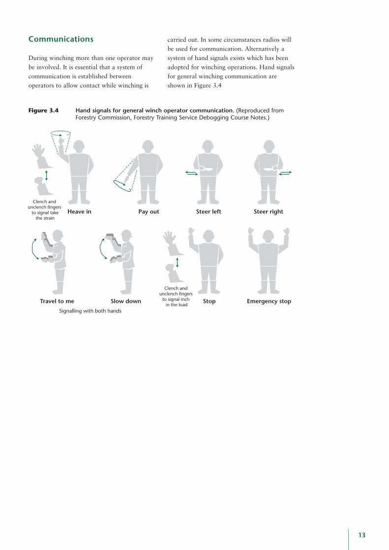
Figure 3.4 Hand signals for general winch operator communication. (Reproduced fromForestry Commission, Forestry Training Service Debogging Course Notes.)
SIGNALLING WITH BOTH HANDS
EMERGENCYS
STEERR
STEER LEFTPAYHEAVEI
Clench & UnclenchFingers To SignalTake In The Strain
STOP
Clench & UnclenchFingers To SignalInch In The Load
SLOWTRAV EL TOM
Heave in Pay out Steer left Steer right
Stop Emergency stopSlow downTravel to me
Signalling with both hands
Clench and unclench fingers
to signal inch in the load
Clench and unclench fingers
to signal takethe strain
Communications
During winching more than one operator may
be involved. It is essential that a system of
communication is established between
operators to allow contact while winching is
carried out. In some circumstances radios will
be used for communication. Alternatively a
system of hand signals exists which has been
adopted for winching operations. Hand signals
for general winching communication are
shown in Figure 3.4

14
4. Selection and use of anchor and fixing points
Trees
Table 4.1 shows a guide to the maximum pullat stump height (in kN) that should be exertedupon green trees and the upper limit of winchrating appropriate.
be through the use of a strop and shackle, re-quiring a notch to be cut in the stump to preventthe strop pulling over the top of the stump.
Vehicles or machinery
Anchorage should be as far away from theload as the length of the wire rope allows toensure a safe working position. Attachment ofwire rope to vehicles must be to a structurallysound load-bearing point. The tow-hitchshould be avoided as its capacity is generallyunknown. Ensure that the wire rope isproperly attached to the pulling machine in thecase of debogging, i.e. to a tow bar and not justa tow hitch. The latter is not designed to copewith large pulling forces; attachment aroundthe machine axle is a more secure method.
Debogging hooks
Debogging hooks may be used for the purposeof anchoring but only as a ‘last resort’ shouldalternative anchorage be unavailable and onlywhere appropriate training has been received.Debogging hooks may pull through the stumpunder large forces and therefore the quality ofthe stump and its anchoring in the groundshould be checked. The use of a terminal pininserted at the point of attachment of the hookto the stump will help to prevent the hookpulling through the stump.
Using strops for load attachment
The configuration of strops will influence theirsafe working load. Figure 4.1 illustrates thechange in strop SWL with different stropconfigurations. As shown, using a strop in achokered fashion will reduce the force thatshould be exerted to 80% of the stated SWL.
DBH(cm)
Max. pullingforce (kN)
Max. straight linepull related to winch
tonnage rating
20 13 1.3 t
30 30 3.0 t
40 53 5.3 t
50 83 8.3 t
60 120 12.0 t
When using trees as anchor points the bearingstrength of the tree is unknown, and will varywith rooting, soil type, soil moisture andpresence of decay. Trees growing on shallowsoil or boggy ground should be avoided ifpossible (likely to be a difficult criterion tomeet in areas where machinery is likely tobecome bogged). Dry or rotten stumps shouldbe avoided as anchor points. If there is doubtabout the load-bearing capacity of an anchortree it should be further anchored back toadjacent tree(s). If the tree selected foranchoring is not to be subsequently felled, caremust be taken not to damage the standing tree.
Stumps
When using stumps for anchor points in winch-ing operations secure attachment is essential.Attachment of the wire rope to the stump may
Straight
1.0
Chokered
0.8
7° to 45°
1.4
45° to 60°
1.0
Baskets
Figure 4.1 Influence of strop configuration on SWL (the multiplication factor of SWL is shown below).
Parallelto 7°
2.0
Table 4.1
Guide to bearing capacity of standing trees(Reproduced from Samset, I., Winch and cable systems).
15
uncontrollably. The working distance from the
load should be as great as the wire rope will
allow, and the pull should be offset through
the use of a block to allow a winching position
for the operator out of the direct line of pull.
Owing to the exposed operating position of
those involved in manual winching, the
operator has little protection should failure
occur. It is therefore essential that these aspects
are fully covered during the planning, organising
and risk assessment of the operation.
Regarding mechanised winching there is little
advice regarding safety guarding suitable for
machine cabs. Due to the varying nature and
size of equipment components current machine
cab guarding may be insufficient for the
purpose. There is currently no standard for
assessing the suitability of such guarding for
winching operations.
During the winching operation anyone who is
not directly involved should move to a safe
distance of at least twice the distance of the wire
rope in use under tension. The operator should
remain in the cab or in the designated safe
operating position until tension has been released
from the winch cable; and the winch system
should never be left assembled and under tension.
As far as tree takedown is concerned, during
the operation there is no guarantee of the exact
direction in which the hung-up tree will move
or fall. This is an especially important
consideration when takedown takes place on
sloping ground and there is potential for the
tree to slide down slope during the pull. Owing
to the nature of tree crowns, where trees are
likely to be hung up, precise directional control
of the stem during winching is difficult. If the
tree deviates from the intended direction of
takedown mid pull, there could be significant
danger to the operator. This reinforces the need
for the operator to take up a safe working
position with a clearly identified ‘escape route’
in case the direction of the tree deviates from
that intended (see examples marked in green in
Appendix 2).
The potential for equipment to be thrown
through the air should a breakage occur increases
with the elasticity of the system. Trees used in
a system may impart some elasticity, especially
if support strops are placed high up the stem.
Wire rope stretches very little when used in
pulling applications. As such, it is probable that
if equipment failure occurs during normal winch
takedown/debogging, the rope will simply slump
to the ground, in a reasonably safe manner. The
main danger in such cases is that the load being
winched ceases to be supported and may move
Training will address safety issues connected
with winching which fall outside the scope of
this guide. These include such factors as the
weather conditions, e.g. strong winds, at the
time of winching.
Information and courses relating to the
appropriate training of winch operators in
forest operations can be obtained from
Forestry Training Services (see References and
useful sources of information for contact
details). Information about the use of winches
in forestry can be obtained from the AFAG
Guides listed in the References. It is essential
that anyone involved in winching in forest
operations must have first received the
appropriate training both in the technical use
of winches and in appropriate first aid.
5. Identification of safe working positions
6. Training requirements

16
• Protective helmet (Complying with EN 397)• Suitable eye protection (mesh visor complying with EN 1731 or safety glasses to EN 166)• Ear protection if working near or with a tractor (complying with EN 352)• Gloves• Protective boots with good grip (complying with EN 345-1)• Non-snag outer clothing• First aid kit including large wound dressing• High visibility clothing when working on or near the public highway or when working with
other machinery
Table 7.1 Safety clothing requirements for winch operations (Reproduced from AFAG Guide310: Use of winches in directional felling and takedown. EN: European Norm: European-wide safety standard).
7. Personal protective equipment (PPE)
The appropriate PPE for winching operations
is set out in Table 7.1. It is accepted practice
that gloves are worn by those involved,
however, there is no designated specification
for gloves suitable for winching operations.
Suitable gloves should afford the operator
adequate protection from injury, principally in
the handling of wire rope. Commonly during
takedown operations those involved will have
chainsaw gloves and these should provide
acceptable protection during winching. AFAG
Guide 310 states that for all winching
operations suitable work gloves should be
used.

17
Equipment failureThe point at which an element of
equipment breaks (loses structural integrity)
due to loading beyond its capacity.
Force Force (F) = Mass (M) x Acceleration (A):
F=MA
Lifting equipmentAs defined by PUWER 98: How the
Regulations apply to agriculture and
forestry: ‘Any equipment that lifts or lowers
loads, including: processing machines that
lift as part of their function, such as tree
harvesters, bed processors; extraction
machines that lift as part of their function,
such as cable cranes; machines fitted with
log loaders, such as forwarders and
clambunk skidders’.
Lug-all Brand of hand winch with length of wire
rope self-contained within the unit.
Mechanical advantage (MA)Exists in a machine where a machine puts
out more force than is put in.
Movable blockA block included in a winch system that
moves with the load as winching progresses.
Safe working load (SWL)The SWL is the maximum load (as certified
by a competent person) that a piece of
equipment may be placed under, taking into
account particular service conditions.
Safety factorA factor above the SWL above which failure
of an equipment component will occur.
SheaveA ‘wheel’ with a groove over which the
rope passes in a pulley block.
Straight line pullPulling effort whereby the input force
directly acts upon the load, without a
diversion in the angle of pull, i.e. through
the use of a block.
TirforBrand of hand winch.
TrewhellaA clamping device, commonly used within
skyline operations, which allows a secure
fastening point for a length of wire rope at
a given point along the rope’s length; see
key equipment, Figures 2.2–2.6.
Diverted pullUse of a block which allows for a change in
direction of the winch rope, i.e. allowing
the operator to take up a safe working
position, offset from the line of pull.
Appendix 1
Definition of terms

18
Appendix 2
Winch set-up scenarios and debogging
Winch set-up scenarios: tree takedown (forces of friction are not included for thepurposes of simplification).
Escape route
To winchanchor tree
1 t rated winch
2 t rated chokerchain or strop
2 t rated winch
1.5 t pull exertedon hung-up tree
Anchor tree/stump
x
T
1 t rated chokerchain or stropand shackle
Escape route
To winchanchor tree
1 t rated winch
4 t rated chokerchain or strop,
shackle and block
3.3 t pull exerted on hung-up tree
Anchor tree/stump
3x
x
T
3 t rated chokerchain or strop,
shackle and block
3 t pull exerted on anchor tree
Escape route
To winchanchor tree
1 t rated winch
3 t rated chokerchain or strop,
shackle and block
2.4 t pull exerted on hung-up tree
Anchor tree/stump
2x
x
T
2 t rated chokerchain or strop
and block
2.4 t pull exerted on anchor tree
Figure A.1
Angle X = 50°. 1 t rated hand winch (T): Force onhung-up tree = 1 t. Advantage of setup: change indirection of pull: allows operator to take up a safeworking position. NB Force on anchor tree 2T(cos X) = 2 t x 0.6 = 1.3 t
Figure A.2
Angle X = 40°. 1 t rated hand winch (T): Force onanchor tree = 1 t. Advantage of setup: Multiplicationof takedown force on hung-up tree = 2T(cos X) = 2 t x0.8 = 1.5 t
Figure A.4
Angle X = 20°. 1 t rated hand winch (T): Advantage ofsetup: Multiplication of takedown force on hung-uptree = (Tcos 3X) + (3TcosX) = 0.5 t + 2.8 t = 3.3 t
Figure A.3
Angle X = 25°. 1 t rated hand winch (T): Advantage ofsetup: Multiplication of takedown force on hung-uptree = (Tcos 2X) + (2TcosX) = 0.6 t + 1.8 t = 2.4 t
Escape route
To winchanchor tree
1.3 t exertedon anchor tree
2 t strop2 t block
1 t rated winch
1 t rated chokerchain or strop
and shackle
1 t pull exertedon hung-up tree
Anchor tree/stump
x
T

19
Winch set-up scenarios: debogging (forces of friction are not included for the purposes ofsimplification).
Bogged machineweight = 4 t
Escape route
5.4 t pull on machine
3 t ratedwinch
3 t rated stropand shackle
6 t rated blockand shackle
Force on anchortree = 3 t
Winch securelyanchored
x T (= 3 t)
Bogged machineweight = 10 t
10.5 t pull on machine
4 t rated vehiclemounted winch
Protected workingposition provided
by machine cab
8 t rated strop and
shackle
11 t rated blockand shackle
Force on anchortree = 8 t
Winch securelyanchored
T (= 4 t)
x 2x
Protected workingposition providingby machine cab
Vehicle securelyanchored
4 t ratedstrop and
shackle
5 t rated strop,shackle and block
4 t
Mechanised 4 tvehicle mounted
winch for takedown
4.8 t exerted on anchor tree
T
x
Figure A.6
Similar set-up to Figure A.1: mechanised winchreplaces hand winch. Angle X = 50°. 4 t ratedmechanised winch (T): Force on hung-up tree = 4 t.Advantage of Setup: change in direction of pull: allowsoperator to take up a safe working position. NB forceon anchor tree = 2T(cos X) = 8 t x 0.6 = 4.8 t
Figure A.8
Angle X = 21°. Pull required to debog machine: 10.4t. Winch rated at 4 t. Force exerted on anchor tree 8 t.Force exerted on bogged vehicle through winch set-up = (T cos 2X) + (2TcosX) = 3 t + 7.5 t = 10.5 t
Figure A.7
Angle X = 20°. Pull required to debog machine: 4.5 t.Winch rated at 3 t. Force exerted on anchor tree 3 t.Force exerted on vehicle through winch set-up = 2T(cos X) = 6 t x 0.9 t = 5.4 t
Protected workingposition providingby machine cab
Vehicle securelyanchored
6.4 t pull exerted on strop, shackle
and block
4 t rated stropand shackle
4 t
Mechanised 4 tvehicle mounted
winch for takedown
6.4 t exerted onhung-up tree
7 t rated strop,shackle and block
Tx
Figure A.5
Similar set-up to Figure A.2: mechanised winchreplaces hand winch. Angle X = 40°. 4 t ratedmechanised winch (T): Force on anchor tree = 4 t.Advantage of Setup: Multiplication of takedown forceon hung-up tree = 2T(cos X) = 8 t x 0.8 = 6.4 t

20
Figure A.12
Bogged machineweight = 10 t
Protected working position provided by machine cab
Note: Saferwinching position, than Figure 6.12,
out of the line of pull
4 t rated vehiclemounted winch
8 t pull on anchor tree
4 t pull on anchor
tree
8 t rated block, shackle and stropCombined 16 t
pull on vehicle
8 t ratedblock, shackle
and strop
Winch securelyanchored
T (= 4 t)
Bogged machineweight = 10 t
Protected working position provided by machine cab
4 t rated vehiclemounted winch
4 t pull on anchor tree
16 t rated block, shackle and strop
8 t rated block, shackle
and strop
16 t pull on vehicle
4 t ratedshackle and
stropWinch securely
anchored
T (= 4 t)
Bogged machineweight = 10 t
Protected workingposition providedby machine cab
4 t ratedshackle
8 t rated block and
shackle
T (= 4 t)
8 t rated block and
shackle
4 t ratedshackle
8 t rated block and
shackle
Winch securelyanchored
T (= 4 t)
Bogged machineweight = 10 t
OR
2xxx 3x
Escape route
Bogged machineweight = 10 t
10.4 t pull on machine
3 t ratedwinch
9 t rated strop and
shackle
11 t rated blockand shackle
Force on anchortree = 9 t
Winch securelyanchored
T (= 3 t)
Figure A.10
A. Angle X = 15°. Pull required to debog machine:10.4 t. Winch rated at 4 t. Force exerted on anchortree 8 t. Force exerted on bogged vehicle throughwinch set-up = (T cos 2X) + (2TcosX) = 3.1 t + 7.5 t =10.6 t B. Angles between wire rope sections so small soas to be considered negligible. Thus: Winch rated 4 t.Force exerted on bogged vehicle through winch set-up= 4 t x 3 = 12 t
Figure A.9
Angle X = 18°. Pull required to debog machine: 10.4t. Winch rated at 3 t. Force exerted on anchor tree 9 t.Force exerted on bogged vehicle through winch set-up = (T cos 3X) + (3TcosX) = 1.8 t + 8.6 = 10.4 t
Figure A.11
In these examples the multiple blocks used in the set-ups introduce multiple angles of force exerted upon theload. Owing to the complexity of these set-ups, the calculations involved are so lengthy that an operator is best toapply the general rule of thumb: calculating the maximum forces that could be at work within the system. Hence:Figure A.11: Force exerted on bogged vehicle = 4 x 4 t = 16 tFigure A.12: Force exerted on bogged vehicle = 4 x 4 t = 16 t
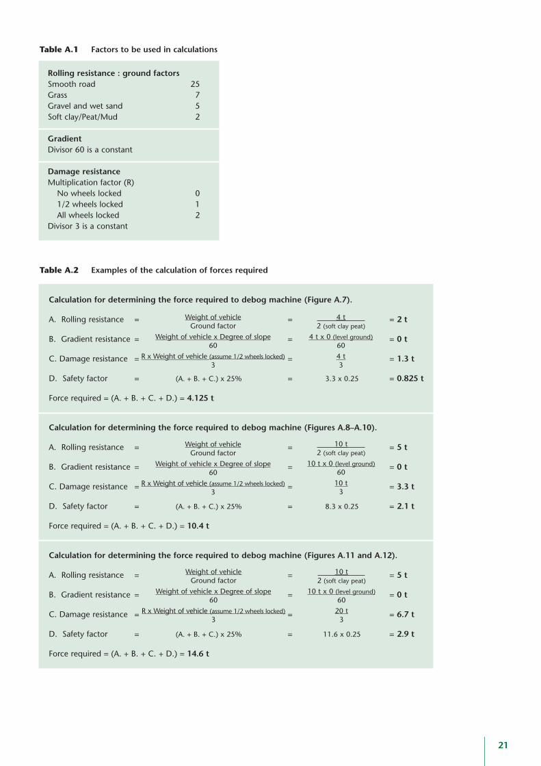
Rolling resistance : ground factors Smooth road 25Grass 7Gravel and wet sand 5Soft clay/Peat/Mud 2
GradientDivisor 60 is a constant
Damage resistanceMultiplication factor (R)
No wheels locked 01/2 wheels locked 1All wheels locked 2
Divisor 3 is a constant
21
Calculation for determining the force required to debog machine (Figure A.7).
A. Rolling resistance = = = 2 t
B. Gradient resistance = = = 0 t
C. Damage resistance = = = 1.3 t
D. Safety factor = (A. + B. + C.) x 25% = 3.3 x 0.25 = 0.825 t
Force required = (A. + B. + C. + D.) = 4.125 t
Calculation for determining the force required to debog machine (Figures A.8–A.10).
A. Rolling resistance = = = 5 t
B. Gradient resistance = = = 0 t
C. Damage resistance = = = 3.3 t
D. Safety factor = (A. + B. + C.) x 25% = 8.3 x 0.25 = 2.1 t
Force required = (A. + B. + C. + D.) = 10.4 t
Calculation for determining the force required to debog machine (Figures A.11 and A.12).
A. Rolling resistance = = = 5 t
B. Gradient resistance = = = 0 t
C. Damage resistance = = = 6.7 t
D. Safety factor = (A. + B. + C.) x 25% = 11.6 x 0.25 = 2.9 t
Force required = (A. + B. + C. + D.) = 14.6 t
Weight of vehicleGround factor
Weight of vehicle x Degree of slope60
R x Weight of vehicle (assume 1/2 wheels locked)3
Weight of vehicleGround factor
Weight of vehicle x Degree of slope60
R x Weight of vehicle (assume 1/2 wheels locked)3
Weight of vehicleGround factor
Weight of vehicle x Degree of slope60
R x Weight of vehicle (assume 1/2 wheels locked)3
4 t2 (soft clay peat)
4 t x 0 (level ground)604 t3
10 t2 (soft clay peat)
10 t x 0 (level ground)60
10 t3
10 t2 (soft clay peat)
10 t x 0 (level ground)60
20 t3
Table A.1 Factors to be used in calculations
Table A.2 Examples of the calculation of forces required

22
Publications
AFAG GuidesThe following Arboriculture and Forestry
Advisory Group (AFAG) safety guides are
relevant to winching operations and should be
read in conjunction with this report:
310: Uses of winches in directional felling and
takedown
501: Tractors in tree work
502: Extraction by skidder
504: Extraction by cable crane
502 and 504: Cover wider operational safety
aspects regarding the use of components
common to winch systems.
AFAG guides are printed and published by the
Health and Safety Executive.
Forestry CommissionANON (1974).
Health and Safety at Work etc. Act 1974.
HMSO, London.
FORESTRY COMMISSION AND
TECHNICAL DEVELOPMENT (1994).
Cableway rope discard criteria.
Technical Note 8/94.
Technical Development, Ae, Dumfries.
FORESTRY COMMISSION AND
TECHNICAL DEVELOPMENT (1998).
The Grizedale debogging equipment trailer.
Information Note 4/98.
Technical Development, Ae, Dumfries.
OtherHEALTH AND SAFETY EXECUTIVE (1999).
PUWER 98: How the Regulations apply to
agriculture and forestry. AIS 27
Health and Safety Executive Books, Sudbury,
Suffolk.
HEALTH AND SAFETY EXECUTIVE (2000).
LOLER: How the Regulations apply to
forestry. AIS 29
Health and Safety Executive Books, Sudbury,
Suffolk.
SAMSET, I. (1985).
Winch and cable systems.
Martinus Nijhoff, Dordrecht, Netherlands.
Contacts
Forestry Training Services HeadquartersAe Management Training Centre
Ae Village
Parkgate
Dumfries
DG1 1QB
Tel. 01387 860637
Technical Development BranchForest Research
Ae Village
Parkgate
Dumfries
DG1 1QB
Tel. 01387 860264
Appendix 3
References and useful sources of information

Notes
23

24
Notes

231 Corstorphine RoadEdinburghEH12 7AT
www.forestry.gov.uk£6


![Helicopter winching accident Insert document title ... · ATSB Transport Safety Report [Insert Mode] Occurrence Investigation XX-YYYY-#### Final Investigation Helicopter winching](https://static.fdocuments.us/doc/165x107/5e7acd12513e55103a6bbd9c/helicopter-winching-accident-insert-document-title-atsb-transport-safety-report.jpg)


