Technical Guidance References - Ferramentas
N9 N Technical Guidance References Technical Guidance Turning Edition ..................................................... N10 Milling Edition ....................................................... N15 Endmilling Edition ............................................... N19 Drilling Edition ...................................................... N22 SUMIBORON Edition ........................................... N27 References SI Unit Conversion List ....................................... N31 Steel and Non-Ferrous Metal Symbols Chart (1) .... N32 Steel and Non-Ferrous Metal Symbols Chart (2) .... N33 Hardness Scale Comparison Chart .................. N34 Standard of Tapers ............................................... N35 Dimensional Tolerances for Regularly Used Fits ........ N36 Dimensional Tolerances and Fits ...................... N38 Finished Surface Roughness ............................ N39 Technical Guidance / References N9 to N39 N N
Transcript of Technical Guidance References - Ferramentas
N9
N
Technical GuidanceReferences
Technical Guidance
Turning Edition .....................................................N10
Milling Edition .......................................................N15
Endmilling Edition ...............................................N19
Drilling Edition ......................................................N22
SUMIBORON Edition ...........................................N27
References
SI Unit Conversion List .......................................N31
Steel and Non-Ferrous Metal Symbols Chart (1) ....N32
Steel and Non-Ferrous Metal Symbols Chart (2) ....N33
Hardness Scale Comparison Chart ..................N34
Standard of Tapers ...............................................N35
Dimensional Tolerances for Regularly Used Fits ........N36
Dimensional Tolerances and Fits ......................N38
Finished Surface Roughness ............................N39
Technical Guidance / References
N9 to N39 N
N
N10
N
Technic
al Guida
nce /
Referen
ces
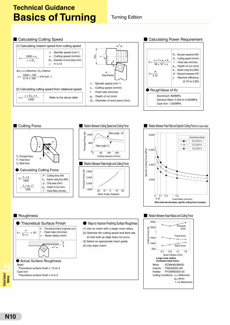
■ Relation Between Cutting Speed and Cutting Force
1,600
800
0240160800
Cutting Speed (m/min)
Rake angle: -10°
Rake angle: 0°
Prin
cipa
l For
ce (
N)
■ Relation Between Rake Angle and Cutting Force
1,600
2,000
2,400
2,800
20 10 0 -10 -20
Rake Angle (Degree)
Prin
cipa
l For
ce (
N)
2,000
4,000
6,000
8,000
0 0.10.04
0.2 0.4
Feed Rate (mm/rev)
Traverse Rupture Strength
When feed rate decreases, specific cutting force increases.
Spe
cific
Cut
ting
For
ce (
MP
a)
800MPa600MPa400MPa
■ Relation Between Feed Rate and Specific Cutting Force (For Carbon Steel)
500
1000
1500
3500
4000
0.4 0.8 1.2 1.6
Nose Radius (mm)
Principalforce
Feed force
Back force
Large nose radiusincreases back force.
Cut
ting
For
ce (
N)
■ Relation Between Nose Radius and Cutting Force
■ Cutting Force
P = k c × q1,000
= k c × a p × f
1,000
P : Cutting force (kN)k c : Specific cutting force (MPa)q : Chip area (mm2)a p : Depth of Cut (mm)f : Feed Rate (mm/rev)
● Calculating Cutting Force
Fc: Principal forceFf : Feed forceFp: Back force
Ff
Fp
Fc
● Theoretical Surface Finish
■ Roughness
● Ways to Improve Finishing Surface Roughness(1) Use an insert with a larger nose radius.
(2) Optimise the cutting speed and feed rate
so that built-up edge does not occur.
(3) Select an appropriate insert grade.
(4) Use wiper insert
● Actual Surface RoughnessSteel: Theoretical surface finish x 1.5 to 3Cast iron: Theoretical surface finish x 3 to 5
h = f 2
× 103
8 × r e
h : Theoretical surface roughness (mm)f : Feed rate (mm/rev)r e : Nose radius (mm)
f
h
U
Pc : Net power requirement (KW)Vc : Cutting speed (m/min)f : Feed rate (mm/rev)
a p : Depth of cut (mm)k c : Specific cutting force (MPa)H : Required horsepower (HP)
h : Machine efficiency(0.70 to 0.85)
■ Calculating Power Requirement
● RoughValue of Kc
Aluminium: 800MPaGeneral Steel: 2,500 to 3,000MPaCast Iron: 1,500MPa
Pc =vc × f × a p × k c60 × 103 × h
H = Pc
0.75
■ Calculating Cutting Speed
· n : Spindle speed (min-1)
· vc : Cutting speed (m/min)
· f : Feed rate (mm/rev)
· ap : Depth of cut (mm)
· Dm : Diameter of work piece (mm)
n : Spindle speed (min-1)vc : Cutting speed (m/min)Dm : Diameter of work piece (mm)
p : 3.14
(1) Calculating rotation speed from cutting speed
Refer to the above table
(2) Calculating cutting speed from rotational speed
(Ex.) vc=150m/min, Dm=100mm
n =1,000 × 150
= 478 (min -1)3.14 × 100
øD
m
n
a p
f
n = 1,000 × vc
p × Dm
vc =p × Dm × n
1,000
Technical Guidance
Basics of Turning Turning Edition
Feed Direction
Work : SCM440(38HS)Inserts : TNGA2204 SSHolder : PTGNR2525-43Cutting Conditions : vc=100m/min
ap=4mm f =0.45mm/rev
N11
N
Technical Guidance / References
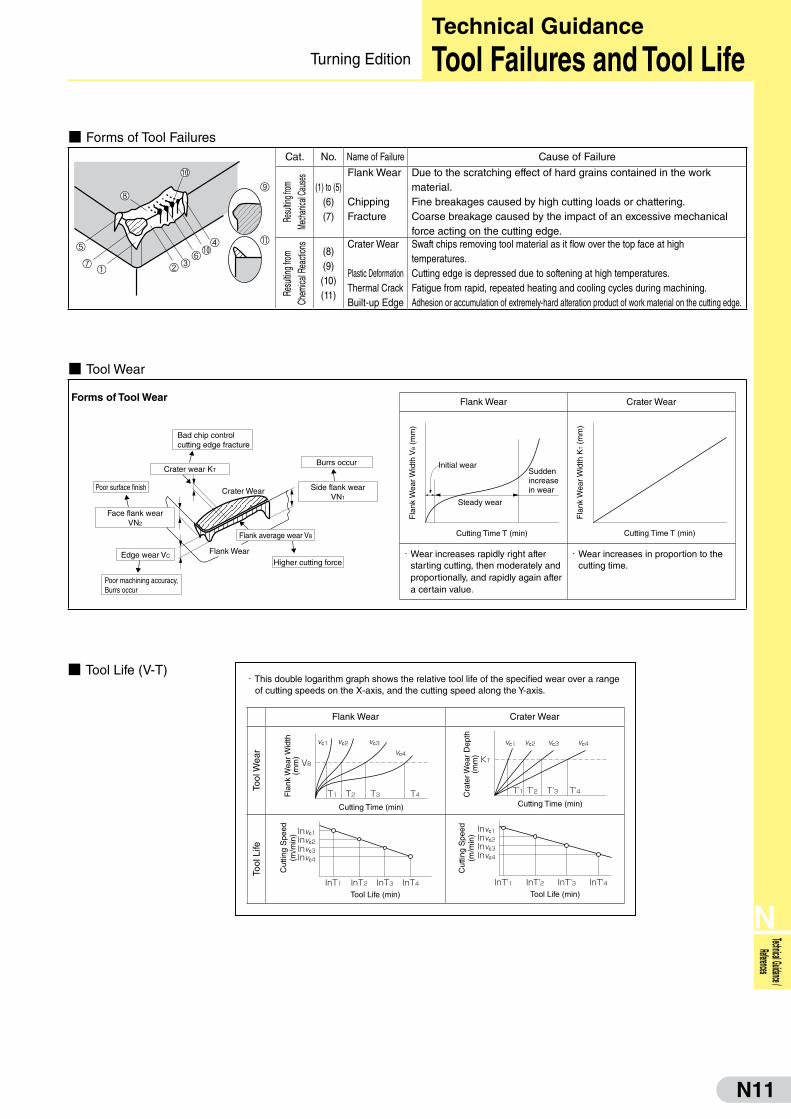
■ Forms of Tool FailuresCat. No. Name of Failure Cause of Failure
Resu
lting f
rom
Mech
anica
l Cau
ses
(1) to (5)(6)(7)
Flank Wear
ChippingFracture
Due to the scratching effect of hard grains contained in the workmaterial.Fine breakages caused by high cutting loads or chattering.Coarse breakage caused by the impact of an excessive mechanical force acting on the cutting edge.
Resu
lting f
rom
Chem
ical R
eacti
ons
(8)(9)(10)(11)
Crater Wear
Plastic DeformationThermal CrackBuilt-up Edge
Swaft chips removing tool material as it flow over the top face at hightemperatures.Cutting edge is depressed due to softening at high temperatures.Fatigue from rapid, repeated heating and cooling cycles during machining.Adhesion or accumulation of extremely-hard alteration product of work material on the cutting edge.
■ Tool Wear
・ This double logarithm graph shows the relative tool life of the specified wear over a range of cutting speeds on the X-axis, and the cutting speed along the Y-axis.
■ Tool Life (V-T)
Flank Wear Crater Wear
Cutting Time T (min)
Initial wear
Steady wear
Suddenincreasein wear
Fla
nk W
ear W
idth
VB (
mm
)
Cutting Time T (min)
Fla
nk W
ear W
idth
KT (
mm
)
・ Wear increases rapidly right after starting cutting, then moderately and proportionally, and rapidly again after a certain value.
・ Wear increases in proportion to the cutting time.
Flank Wear Crater Wear
Tool
Wea
r
Cutting Time (min)
Fla
nk W
ear W
idth
(mm
)
VB
vc1
T1 T2 T3 T4
vc2 vc3
vc4
Cutting Time (min)
Cra
ter W
ear
Dep
th(m
m)
vc1 vc3 vc4vc2
KT
T'1 T'2 T'3 T'4
Tool
Life
Tool Life (min)
Cut
ting
Spe
ed(m
/min
) Invc1Invc2Invc3Invc4
InT1 InT2 InT3 InT4Tool Life (min)
Cut
ting
Spe
ed(m
/min
)
Invc1Invc2Invc3Invc4
InT'1 InT'2 InT'3 InT'4
Forms of Tool Wear
Burrs occur
Higher cutting force
Poor surface finish
Edge wear VC
Bad chip controlcutting edge fracture
Poor machining accuracy,Burrs occur
Side flank wearVN1
Flank Wear
Crater Wear
Flank average wear VB
Face flank wearVN2
Crater wear KT
Technical Guidance
Tool Failures and Tool LifeTurning Edition
N12
N
Technic
al Guida
nce /
Referen
ces
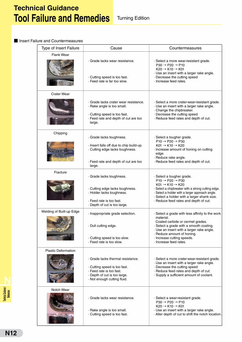
■ Insert Failure and Countermeasures
Type of Insert Failure Cause Countermeasures
Flank Wear
· Grade lacks wear resistance.
· Cutting speed is too fast.· Feed rate is far too slow.
· Select a more wear-resistant grade. P30 → P20 → P10 K20 → K10 → K01
· Use an insert with a larger rake angle.· Decrease the cutting speed· Increase feed rates.
Crater Wear
· Grade lacks crater wear resistance.· Rake angle is too small.
· Cutting speed is too fast.· Feed rate and depth of cut are too large.
· Select a more crater-wear-resistant grade.· Use an insert with a larger rake angle.· Change the chipbreaker.· Decrease the cutting speed· Reduce feed rates and depth of cut.
Chipping· Grade lacks toughness.
· Insert falls off due to chip build-up.· Cutting edge lacks toughness.
· Feed rate and depth of cut are too large.
· Select a tougher grade. P10 → P20 → P30 K01 → K10 → K20
· Increase amount of honing on cutting edge.
· Reduce rake angle.· Reduce feed rates and depth of cut.
Fracture· Grade lacks toughness.
· Cutting edge lacks toughness.· Holder lacks toughness.
· Feed rate is too fast.· Depth of cut is too large.
· Select a tougher grade. P10 → P20 → P30 K01 → K10 → K20
· Select a chipbreaker with a strong cutting edge.· Select a holder with a larger approach angle.· Select a holder with a larger shank size.· Reduce feed rates and depth of cut.
Welding of Built-up Edge· Inappropriate grade selection.
· Dull cutting edge.
· Cutting speed is too slow.· Feed rate is too slow.
· Select a grade with less affinity to the work material.Coated carbide or cermet grades.
· Select a grade with a smooth coating.· Use an insert with a larger rake angle.· Reduce amount of honing.· Increase cutting speeds.· Increase feed rates.
Plastic Deformation
· Grade lacks thermal resistance.
· Cutting speed is too fast.· Feed rate is too fast.· Depth of cut is too large.· Not enough cutting fluid.
· Select a more crater-wear-resistant grade.· Use an insert with a larger rake angle.· Decrease the cutting speed· Reduce feed rates and depth of cut.· Supply a sufficient amount of coolant.
Notch Wear
· Grade lacks wear resistance.
· Rake angle is too small.· Cutting speed is too fast.
· Select a wear-resistant grade. P30 → P20 → P10 K20 → K10 → K01
· Use an insert with a larger rake angle.· Alter depth of cut to shift the notch location.
Technical Guidance
Tool Failure and Remedies Turning Edition

N13
N
Technical Guidance / References
■ Type of Chip GenerationSpiralling Shearing Tearing Cracking
Sha
pe
Work material Work material Work material Work material
Con
ditio
n
Continuous chips with good surface finish.
Chip is sheared and separated by the shear angle.
Chips appear to be torn from the surface.
Chips crack before reaching the cutting point.
Appli
catio
n
Steel, Stainless steel
Steel, Stainless steel (Low speed)
Steel, Cast iron (very low speed, very small feed rate)
Cast iron, Carbon
Influ
ence
Fac
tor
■ Factor of Improvement Chip Control
(1) Increase Feed Rate (f)
f1
t1t1
f2
t2t2
f‥‥f2>f1 then t2>t1
When feed rate increases, chips become thick and chip control improves.
(2) Decrease Side Cutting Edge (θ )
f f
t1 t2
θ1:1θ2:2
:‥‥:2<:1 then t2>t1
Even if feed rate is the same, smaller side cutting edge angle makes chips thick and chip control improves.
(3) Decrease Nose Radius (re)
f f
O1 O2
t2t1t1t2
O‥‥O2<O1 then t2>t1
Smallnoseradius
Largenoseradius
Even if feed rate is the same, a smaller nose radius makes chip thick and chip control improves.
* Cutting force increases in proportion with the length of the contact surface. Therefore, a larger nose radius increases back force which induces chattering. With the same feed rate, a smaller nose radius produces a rougher surface finish.
■ Type of Chip Control
Chip Types
Depth A B C D E
Large
Small
Eval
uatio
n NC Lathe(For Automation) H H S S JGeneral Lathe(For Safety) H S S S~J H
Good: C type, D typeA type: Twines around the tool or workpiece, damages the machined
surface and affects safety.Poor B type: Causes problems in the automat ic chip conveyor and chipping occurs easi ly.
E type: Causes spraying of chips, poor machined surface due to chattering, chipping, large cutting force and high temperatures.
{D
epth
of C
ut (
mm
) 4.0
2.0
0.1 0.2 0.3 0.4 0.5
Feed Rate (mm/rev)
Sid
e C
uttin
g E
dge
Ang
le
45°
15°
0.2 0.25 0.3 0.35
Feed Rate (mm/rev)
Nos
e R
adiu
s (m
m)
1.6
0.8
0.4
0.5 1.0 1.5 2.0
Depth of Cut (mm)
EasyLargeSmall
Fast
Work deformationRake angle
D.O.C.Cutting speed
DifficultSmallLargeSlow
Technical Guidance
Chip ControlTurning Edition

N14
N
Technic
al Guida
nce /
Referen
ces
■ Cutting Methods in Threading
Cutting Method CharacteristicsRadian Infeed
· Most common threading technique, used mainly for small pitch threads.· Easy to change cutting conditions such as depth of cut, etc.· Longer contact points lead to more chatter.· Difficult to control chip evacuation.· Damage on the trailing edge gets larger faster.
Flank Infeed
· Effective for large pitch threads and blemish-prone work material surfaces.· Chips evacuate from one side for good chip control.· The trailing edge side is worn, and therefore the flank is easily worn.
Corrected Flank Infeed
· Effective for large pitch threads and blemish-prone work material surfaces.· Chips evacuate from one side for good chip control.· Reduces flank wear on trailing edge side.
Alternating Flank Infeed
· Effective for large pitch threads and blemish-prone work material surfaces.· Wears evenly on right and left cut edges.· Since both edges are used alternatively, chip control is sometimes difficult.
Direction of CutFeed Dir.
Leading Edge
Trailing Edge
■ Troubleshooting for Threading
Failure Cause Countermeasures
Cut
ting
Edg
e Fa
ilure
Excessive Cutting Edge Wear · Tool material · Select a more wear-resistant grade
· Cutting condition· Decrease the cutting speed· Optimise coolant flow and density· Change the number of passes.
Uneven Wear on Right and Left Sides
· Insert attachment· Check whether the cutting edge inclination angle is
appropriate for the screw lead angle.· Check whether the tool is mounted properly.
· Cutting condition· Change to corrected flank infeed or alternating flank
infeed
Chipping · Cutting condition · If caused by a built-up edge, increase cutting speed
Breakage · Packing of chips· Supply enough amount of coolant to the cutting
edge.
· Cutting condition· Increase the number of passes while decreasing the depth of cut per pass.· Use different tools for roughing and finishing applications.
Sha
pe a
nd A
ccur
acy
Poor Surface Roughness · Cutting condition· If blemished due to low-speed machining, increase the cutting speed.· If chattering occurs, decrease the cutting speed.· If the depth of cut of the final pass is small, make it larger.
· Tool material · Select a more wear-resistant grade
· Inappropriate cutting edge inclination angle
· Select a correct shim to secure relief on the side of the insert.
Inappropriate Thread Shape · Insert attachment · Check whether the tool is mounted properly.
Shallow Thread Depth
· Small depth of cut · Check cutting depth
· Tool weara · Check damage to the cutting edge.
Technical Guidance
Basics of Threading Turning Edition
N15
N
Technical Guidance / References
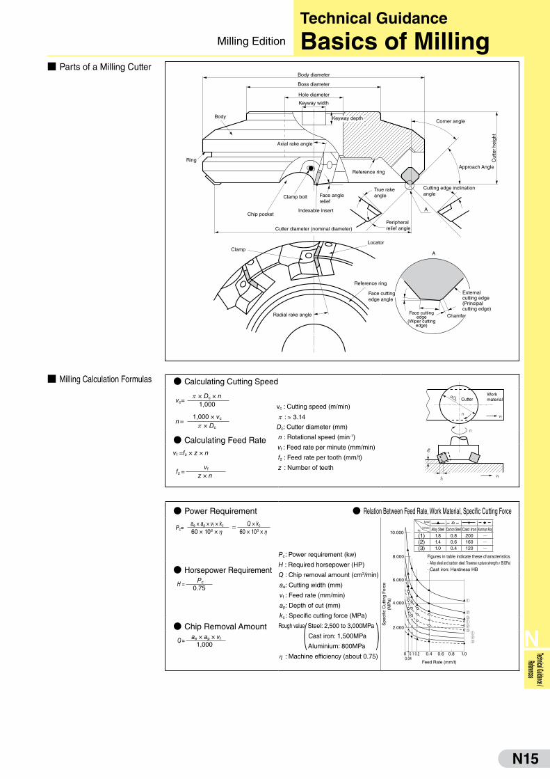
■ Parts of a Milling Cutter
■ Milling Calculation Formulas
Body diameter
Body
Ring
Boss diameter
Hole diameter
Keyway width
Keyway depth
Axial rake angle
Chip pocket
Clamp bolt Face anglerelief
Indexable insert
Cutter diameter (nominal diameter)
LocatorClamp
Radial rake angle
Reference ring
Face cuttingedge angle
Face cuttingedge
(Wiper cuttingedge)
Chamfer
Reference ring
True rakeangle
Peripheralrelief angle
A
A
Cutting edge inclinationangle
Corner angle
Approach Angle
Cut
ter
heig
ht
Externalcutting edge(Principalcutting edge)
● Power Requirement ● Relation Between Feed Rate, Work Material, Specific Cutting Force
10.000
8.000
6.000
4.000
2.000
0 0.10.04
0.2 0.4 0.6 0.8 1.0
Feed Rate (mm/t)
Spe
cific
Cut
ting
For
ce(M
Pa)
● Horsepower Requirement
● Chip Removal Amount
No.
Symbol
Work Material Alloy Steel Carbon Steel Cast Iron Aluminium Alloy(1) 1.8 0.8 200 Q(2) 1.4 0.6 160 Q(3) 1.0 0.4 120 Q
Figures in table indicate these characteristics.· Alloy steel and carbon steel: Traverse rupture strength s B(GPa)· Cast iron: Hardness HB
Pc=ae × ap × vf × kc = Q × kc
60 × 106 × h 60 × 103 × h
H = Pc
0.75
Q = ae × ap × vf
1,000
Pc: Power requirement (kw)
H : Required horsepower (HP)
Q : Chip removal amount (cm3/min)
ae : Cutting width (mm)
vf : Feed rate (mm/min)
ap: Depth of cut (mm)
kc : Specific cutting force (MPa)
Rough value Steel: 2,500 to 3,000MPa
Cast iron: 1,500MPa
Aluminium: 800MPa
h : Machine efficiency (about 0.75)
( )
Technical Guidance
Basics of MillingMilling Edition
● Calculating Cutting Speed
CutterWorkmaterial
øDc
n vf
n
vffz
a p
● Calculating Feed Rate
vc=p × Dc × n
1,000
vf =fz × z × n
fz = vf
z × n
vc : Cutting speed (m/min)
p : ≈ 3.14
Dc: Cutter diameter (mm)
n : Rotational speed (min-1)
vf : Feed rate per minute (mm/min)
fz : Feed rate per tooth (mm/t)
z : Number of teeth
n =1,000 × vc
p × Dc
N16
N
Technic
al Guida
nce /
Referen
ces
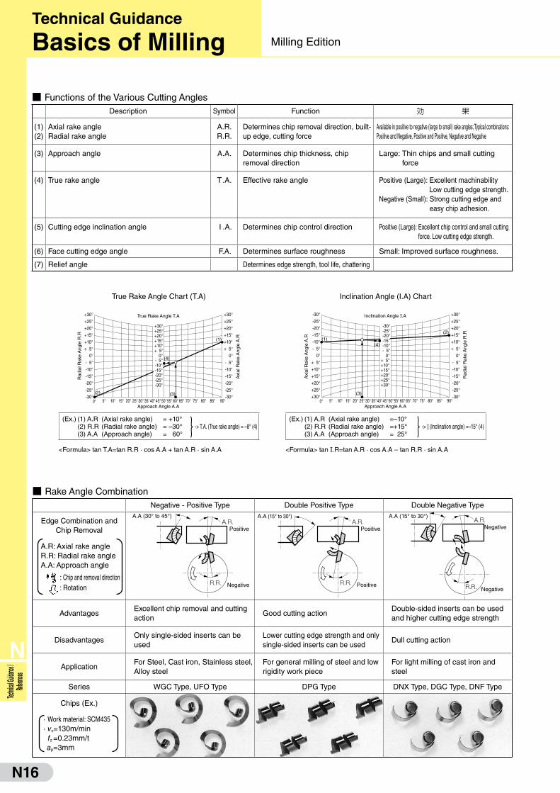
■ Rake Angle CombinationNegative - Positive Type Double Positive Type Double Negative Type
Edge Combination andChip Removal
A.R: Axial rake angleR.R: Radial rake angleA.A: Approach angle
: Chip and removal direction : Rotation
A.A (30° to 45°)A.R. Positive
R.R. Negative
A.A (15° to 30°)A.R. Positive
R.R. Positive
A.R.
R.R. Negative
Negative
A.A (15° to 30°)
AdvantagesExcellent chip removal and cutting action
Good cutting actionDouble-sided inserts can be used and higher cutting edge strength
DisadvantagesOnly single-sided inserts can be used
Lower cutting edge strength and only single-sided inserts can be used
Dull cutting action
ApplicationFor Steel, Cast iron, Stainless steel, Alloy steel
For general milling of steel and low rigidity work piece
For light milling of cast iron and steel
Series WGC Type, UFO Type DPG Type DNX Type, DGC Type, DNF Type
Chips (Ex.)
· Work material: SCM435· vc=130m/min fz =0.23mm/t ap=3mm
■ Functions of the Various Cutting AnglesDescription Symbol Function 効 果
(1) (2)
Axial rake angleRadial rake angle
A.R. R.R.
Determines chip removal direction, built-up edge, cutting force
Available in positive to negative (large to small) rake angles; Typical combinations: Positive and Negative, Positive and Positive, Negative and Negative
(3) Approach angle A.A. Determines chip thickness, chip removal direction
Large: Thin chips and small cutting force
(4) True rake angle T.A. Effective rake angle Positive (Large): Excellent machinability Low cutting edge strength.
Negative (Small): Strong cutting edge and easy chip adhesion.
(5) Cutting edge inclination angle I .A. Determines chip control direction Positive (Large): Excellent chip control and small cutting force. Low cutting edge strength.
(6) Face cutting edge angle F.A. Determines surface roughness Small: Improved surface roughness.
(7) Relief angle Determines edge strength, tool life, chattering
True Rake Angle Chart (T.A)
+30°
0° 5° 10° 15° 20° 25° 30° 35°
+25°
+20°
+15°
+10°
+ 5°
0°
- 5°
-10°
-15°
-20°
-25°
-30°
+30°
+25°
+20°
+15°
+10°
+ 5°
0°
- 5°
-10°
-15°
-20°
-25°
-30°
+30°+25°+20°+15°+10°+ 5°
0°- 5°
-20°-25°
-10°-15°
45°50°55° 60° 65° 70° 75° 80° 85° 90°40°Approach Angle A.A
True Rake Angle T.A
-30°
Axi
al R
ake
Ang
le A
.R
Rad
ial R
ake
Ang
le R
.R
(2)
(1)
(3)
(4)
<Formula> tan T.A=tan R.R · cos A.A + tan A.R · sin A.A
(Ex.) (1) A.R(2) R.R(3) A.A
(Axial rake angle)(Radial rake angle)(Approach angle)
= +10°= –30°= 60° } -> T.A. (True rake angle) = –8° (4)
Inclination Angle (I.A) Chart
-30°
0° 5° 10° 15° 20° 25° 30° 35°
-25°
-20°
-15°
-10°
- 5°
0°
+ 5°
+10°
+15°
+20°
+25°
+30°
+30°
+25°
+20°
+15°
+10°
+ 5°
0°
- 5°
-10°
-15°
-20°
-25°
-30°
-30°-25°
-10°- 5°
0°+ 5°
+20°+25°
+10°+15°
45°50°55° 60° 65° 70° 75° 80° 85° 90°40°
+30°
-20°-15°
Approach Angle A.A
Inclination Angle I.A
Axi
al R
ake
Ang
le A
.R
Rad
ial R
ake
Ang
le R
.R
(1)
(3)
(2)
(4)
<Formula> tan I.R=tan A.R · cos A.A – tan R.R · sin A.A
(Ex.) (1) A.R(2) R.R(3) A.A
(Axial rake angle)(Radial rake angle)(Approach angle)
=–10°=+15°= 25° } -> I (Inclination angle) =–15° (4)
Technical Guidance
Basics of Milling Milling Edition
N17
N
Technical Guidance / References
( )
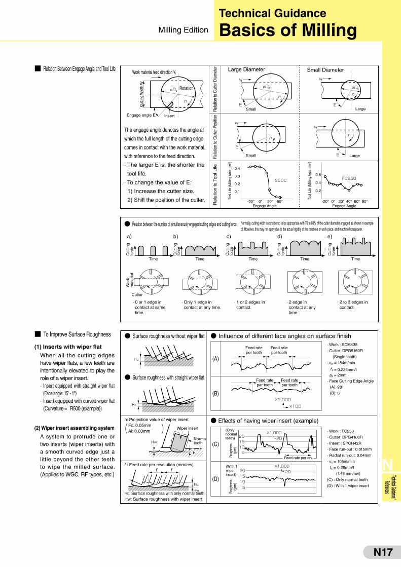
■ Relation Between Engage Angle and Tool Life Work material feed direction Vf
Cut
ting
Wid
th W
øDc
n
Rotation
InsertEngage angle E
The engage angle denotes the angle at
which the full length of the cutting edge
comes in contact with the work material,
with reference to the feed direction.
· The larger E is, the shorter the
tool life.
· To change the value of E:
1) Increase the cutter size.
2) Shift the position of the cutter.
Rela
tion
to C
utte
r Dia
met
er Large Diameter
vf
ESmall
øDc
n
Small Diameter
vf
ELarge
øDc
n
Rela
tion
to C
utte
r Pos
ition
vf
n
E
Small E
vf
n
Large
Rel
atio
n to
Too
l Life 0.4
-30° 0° 30° 60°
0.3
0.2
0.1
S50C
Engage Angle
Tool
Life
(Milli
ng A
rea)
(m2 )
-20° 0° 40° 60° 80°20°
0.6
0.4
0.2
FC250
Engage Angle
Tool
Life
(Milli
ng A
rea)
(m2 )
● Surface roughness without wiper flat ● Influence of different face angles on surface finish
HC
· Work : SCM435
· Cutter: DPG5160R
(Single tooth)
· vc = 154m/min
fz = 0.234mm/t ap = 2mm
· Face Cutting Edge Angle
(A): 28'
(B): 6'
● Surface roughness with straight wiper flat
HF
h: Projection value of wiper insertFc: 0.05mmAl: 0.03mm
HW
Wiper insert
Normalteeth
h
● Effects of having wiper insert (example)
· Work : FC250
· Cutter: DPG4100R
· Insert : SPCH42R
· Face run-out : 0.015mm
· Radial run-out: 0.04mm
· vc = 105m/min
fz = 0.29mm/t
(1.45 mm/rev)
(C) : Only normal teeth
(D) : With 1 wiper insert
f : Feed rate per revolution (mm/rev)
HC
f f
HWHc: Surface roughness with only normal teethHw: Surface roughness with wiper insert
■ To Improve Surface Roughness
(1) Inserts with wiper flat
When all the cutting edges have wiper flats, a few teeth are intentionally elevated to play the role of a wiper insert.· Insert equipped with straight wiper flat
(Face angle: 15' - 1°)· Insert equipped with curved wiper flat
(Curvature ≈ R500 (example))
(2) Wiper insert assembling system
A system to protrude one or two inserts (wiper inserts) with a smooth curved edge just a little beyond the other teeth to wipe the milled surface. (Applies to WGC, RF types, etc.)
● Relation between the number of simultaneously engaged cutting edges and cutting force:
· 0 or 1 edge in contact at same time.
· Only 1 edge in contact at any time.
· 1 or 2 edges in contact.
· 2 edge in contact at any time.
· 2 to 3 edges in contact.
a) b) c) d) e)
Time Time Time Time Time
Cutter
Cut
ting
forc
e
Cut
ting
forc
e
Cut
ting
forc
e
Cut
ting
forc
e
Cut
ting
forc
e
Wor
k m
ater
ial
Normally, cutting width is considered to be appropriate with 70 to 80% of the cutter diameter engaged as shown in example d). However, this may not apply due to the actual rigidity of the machine or work piece, and machine horsepower.
(C)
×1,000
Feed rate per rev.
202015105
(Only normal teeth)
Roug
hnes
s(µ
m)
(D)
×1,0002020
15105
Roug
hnes
s(µ
m)
(With 1wiperinsert)
(A)
Feed rateper tooth
Feed rateper tooth
(B)×2,000
×100
Feed rateper tooth
Feed rateper tooth
Technical Guidance
Basics of MillingMilling Edition

N18
N
Technic
al Guida
nce /
Referen
ces
Failure Basic Remedies Remedy Examples
Cut
ting
Edg
e Fa
ilure
Excessive Flank Wear Tool Material
Cutting
Conditions
· Select a more wear resistant grade.
Carbide P30 � P20
� Coated
K20 � K10 Cermet
· Reduce cutting speeds. Increase
feed rate.
· Recommended insert grades
Excessive Crater Wear Tool Material
Cutting
Conditions
· Select a crater-resistant grade.
· Reduce cutting speeds. Reduce
depth-of-cut and feed rate.
· Recommended insert grades
Chipping Tool Material
Tool Design
Cutting Conditions
· Change to tougher grades.
P10 � P20 � P30
K01 � K10 � K20
· Select a negative-positive cutter configuration with a large
peripheral cutting edge angle (a small approach angle).
· Reinforce the cutting edge (Honing).
· Select a strong edge insert (G � H).
· Reduce feed rates.
· Recommended insert grades
· Recommended cutter: SEC-WaveMill WGX Type· Cutting conditions: Refer to H22
Breakage Tool Material
Tool Design
Cutting
Conditions
· If it is due to excessive low speeds or very low
feed rates, select an adhesion resistant grade.
· If it is due to thermal cracking, select
a thermal impact resistant grade.
· Select a negative-positive (or negative) cutter
configuration with a large peripheral cutting
edge angle (a small approach angle).
· Reinforce the cutting edge (Honing).
· Select a stronger chipbreaker (G � H)
· Increase insert size (Thickness in particular).
· Select appropriate conditions with
regards to the particular application.
· Recommended insert grades
· Recommended cutter: SEC-WaveMill WGX Type
· Insert thickness: 3.18 � 4.76mm
· Insert type: Standard � Strong edge type
· Cutting conditions: Refer to H22
Oth
ers
Unsatisfactory Machined Surface Finish
Tool Material
Tool Design
Cutting
Conditions
· Select an adhesion resistant grade.
Carbide � Cermet
· Improve axial runout of cutting edges.
Use a cutter with less runout
Attach correct inserts.
· Use wiper inserts.
· Use special purpose cutters designed for finishing.
· Increase cutting speeds
· Recommended insert grades
* marked cutters can be fitted with wiper inserts.
Chattering Tool Design
Cutting Conditions
Others
· �Select a cutter with sharp cutting edges.
· Use an irregular pitched cutter.
· Reduce feed rates.
· Improve workpiece and cutter clamp rigidity.
· Recommended cutter
For Steel: SEC-WaveMill WGX Type
For Cast Iron: SEC-DNX Type
For Non-Ferrous Alloy: High Speed cutter for Aluminium RF type
Unsatisfactory Chip Control
Tool Design · Select cutter with good chip removal features.
· Reduce number of teeth.
· Enlarge chip pocket.
· Recommended cutter: SEC-WaveMill WGX Type
Edge Chipping On Workpiece
Tool Design
Cutting Conditions
· Increase the peripheral cutting edge angle (decrease the approach angle).
· Select a stronger chipbreaker (G � L).
· Reduce feed rates.
· Recommended cutter: SEC-WaveMill WGX Type
Burr On WorkpieceTool DesignCutting Conditions
· Select a cutter with sharp cutting edges.
· Increase feed rates.
· Select a low-burr insert.
· Recommended cutter: SEC-WaveMill WGX Type�+ FG Breaker
�DGC Type + FG Breaker
Steel Cast Iron Non-Ferrous Alloy
Finishing T250A (Cermet) ACK200 (Coated Carbide) BN700 (SUMIBORON) DA1000 (SUMIDIA)
Roughing ACP100 (Coated Carbide) ACK200 (Coated Carbide) DL1000 (Coated Carbide)
Steel Cast Iron
Roughing ACP300 (Coated Carbide) ACK300 (Coated Carbide)
Steel Cast Iron
Finishing ACP200 (Coated Carbide) ACK200 (Coated Carbide)
Roughing ACP300 (Coated Carbide) ACK300 (Coated Carbide)
Steel Cast Iron Non-Ferrous Alloy
General
�Purpos
e
Cutter Insert
WGX type*ACP200
(Coated Carbide)
DGC typeACK200
(Coated Carbide)
RF type* H1 (Carbide)
DL1000 (Coated Carbide)
Finish
ing Cutter Insert
WGX type T250A (Cermet)
FMU type BN700 (SUMIBORON)
RF type DA1000 (SUMIDIA)
Steel Cast Iron Non-Ferrous Alloy
Finishing T250A (Cermet) ACK200 (Coated Carbide) DA1000 (SUMIDIA)
Roughing ACP100 (Coated Carbide) ACK200 (Coated Carbide) DL1000 (Coated Carbide)
( � )
( � ){
■ Tool Failure and Remedies
Technical Guidance
Troubleshooting for Milling Milling Edition

N19
N
Technical Guidance / References
■ Parts of an Endmill
■ Calculating Cutting Conditions (Square Endmill)
(Ball Endmill)
Center Cut With Center Hole
Dia
met
er
Body
Cutter sweep
NeckNeckdiameter
Shank
Shank diameter
Shank length
Neck length
Length of cut
Overall length
Centre hole
Land width
Relief widthRadial relief
Radial primary relief angle
Radial secondary clearance angle
Margin width
Margin
LandLand width
Rake face Rake angle
Flute
Flute depth Chip pocket
Roundedflute bottom
Centre hole
Heel
Web thickness Axial primary relief angle
Ball radius
Axial secondary clearance angle
Concavity angle of end cutting edge (*)
Helix angle
Radial cutting edgeEnd cutting edge
Corner
End gash
* Centre area is lower than the periphery
● Calculating Cutting Speed
vc : Cutting speed (m/min) p : ≈ 3.14Dc : Endmill diameter (mm) n : Spindle speed (min-1) vf : Feed rate (mm/min) f : Feed rate per revolution (mm/rev) fz : Feed rate per tooth (mm/t) z : Number of teethap : Axial Depth of Cut (mm)ae : Radial Depth of Cut (mm)R : Ballnose Radius
● Calculating Feed Rate Per Revolution and Per Tooth
● Calculating Notch Width (D1)
● � Cutting speed and feed rate (per revolution and per tooth) are calculated using the same formula as square endmill.
ap
ae
Dc
ap
Dc
D1
R
pf Pick feed
ap Depth of cut
ap
Dc
D1pf
R
Side milling Slotting
Technical Guidance
Basics of EndmillingEndmilling Edition
vc�=p x Dc x n
1,000n�= 1,000 x vc
p x Dc
vf�= n x f f�= vf�n
fz�=f
=vf�
z n x zvf�= n x fz x z
D1= 2 x 2 x R x ap – ap2

N20
N
Technic
al Guida
nce /
Referen
ces
■ Up-cut and Down-cut
■ Relation Between Cutting Condition and Deflection
Endmill
Specifications
Side Milling Slotting
Work: Pre-hardened steel (40HRC)
Cutting Conditions: vc=25m/min ap=12mm ae=0.8mm
Work: Pre-hardened steel (40HRC)
Cutting Conditions: vc=25m/min ap=8mm ae=8mm
Cat.
No.
Number
of Teeth
Helix
Angle
Feed rate Feed rate Feed rate Feed rate
0.16mm/rev 0.11mm/rev 0.05mm/rev 0.03mm/rev
Style Style Style Style
Up-cut Down-cut Up-cut Down-cut Up-cut Down-cut Up-cut Down-cut
2 30°
4 30°
Results· The tool tip tends to back off with the down-cut.
· 4 teeth offers more rigidity and less backing off.
· The side of the slot tends to cut into the up-cut side toward the bottom of the slot.
· 4 teeth offers higher rigidity and less deflection.
● Side Milling ● Slotting
● Wear Amount ● Surface Roughness ● Condition
Work: S50CEndmill: GSX21000C-2D
(ø10mm, 2 teeth)Cutting Conditions: vc=88m/min
(N=2800min-1) vf=530mm/min(fz=0.1mm/t)ap=15mmae=0.5mmSide Milling Dry,Air
fz fz
Work Material Feed Direction
Work material
(a) Up-cut
Work Material Feed Direction
Work material
(b) Down-cut
fz
Work Material Feed Direction
Work material
Up-cut
Down-cut
(a) Up-cut (b) Down-cut
Work Material Feed Direction Work Material Feed Direction
Work material Work material
50 100 150 200 2500
0.010.020.030.040.050.060.070.08
Cutting Length (m)
Fla
nk W
ear W
idth
(m
m)
Up-cut
Down-cut
5
4
3
2
1
0
Up-cut
Down-cut
Up-cut
Down-cut
Feed Dir. Vertical Dir.
Rm
ax (
µm)
Cutting surface
Reference surface
Down-cutUp-cut
GS
X20
800S
-2D
GS
X40
800S
-2D
Technical Guidance
Basics of Endmilling Endmilling Edition
N21
N
Technical Guidance / References
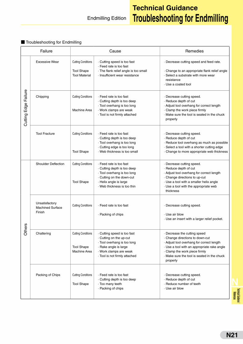
■ Troubleshooting for Endmilling
Failure Cause Remedies
Cut
ting
Edg
e Fa
ilure
Excessive Wear Cutting Conditions
Tool ShapeTool Material
· Cutting speed is too fast· Feed rate is too fast· The flank relief angle is too small· Insufficient wear resistance
· Decrease cutting speed and feed rate.
· Change to an appropriate flank relief angle· Select a substrate with more wear resistance
· Use a coated tool
Chipping Cutting Conditions
Machine Area
· Feed rate is too fast· Cutting depth is too deep· Tool overhang is too long· Work clamps are weak· Tool is not firmly attached
· Decrease cutting speed.· Reduce depth of cut· Adjust tool overhang for correct length· Clamp the work piece firmly· Make sure the tool is seated in the chuck properly
Tool Fracture Cutting Conditions
Tool Shape
· Feed rate is too fast· Cutting depth is too deep· Tool overhang is too long· Cutting edge is too long· Web thickness is too small
· Decrease cutting speed.· Reduce depth of cut· Reduce tool overhang as much as possible· Select a tool with a shorter cutting edge· Change to more appropriate web thickness
Oth
ers
Shoulder Deflection Cutting Conditions
Tool Shape
· Feed rate is too fast· Cutting depth is too deep· Tool overhang is too long· Cutting on the down-cut· Helix angle is large· Web thickness is too thin
· Decrease cutting speed.· Reduce depth of cut· Adjust tool overhang for correct length· Change directions to up-cut· Use a tool with a smaller helix angle· Use a tool with the appropriate web thickness
UnsatisfactoryMachined SurfaceFinish
Cutting Conditions · Feed rate is too fast
· Packing of chips
· Decrease cutting speed.
· Use air blow· Use an insert with a larger relief pocket.
Chattering Cutting Conditions
Tool Shape Machine Area
· Cutting speed is too fast· Cutting on the up-cut· Tool overhang is too long· Rake angle is large· Work clamps are weak· Tool is not firmly attached
· Decrease the cutting speed· Change directions to down-cut· Adjust tool overhang for correct length· Use a tool with an appropriate rake angle· Clamp the work piece firmly· Make sure the tool is seated in the chuck properly
Packing of Chips Cutting Conditions
Tool Shape
· Feed rate is too fast· Cutting depth is too deep· Too many teeth· Packing of chips
· Decrease cutting speed.· Reduce depth of cut· Reduce number of teeth· Use air blow
Technical Guidance
Troubleshooting for EndmillingEndmilling Edition
N22
N
Technic
al Guida
nce /
Referen
ces
先端角
Margin width
Margin Body clearance
FluteFl
ute
wid
thLand widthChisel edge angle
Cutting edge
Chisel edge corner
Chisel edge
Depth of body clearance
Diameter of body clearanceChisel edge length
Web
thic
knes
s
Web thinning Web Cutter sweep
Relief angle
Rak
e an
gle
A:B or A/B = Flute width ratio
Straight shank
Tang length
Tang thickness
A
B
Flank
Height of point
Dril
ldi
amet
er
Cuttingedge
Outercorner
Heel
Body clearance
Rake face
Point angle
Leading edge
Back taper
Lead
Helix angle
Flute length
Overall length
Shank length
Taper shank
Necklength
Neck Tang
Tang
thic
knes
s
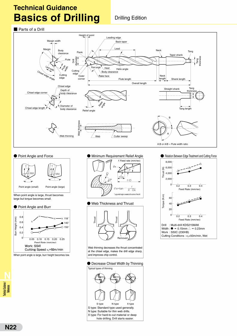
■ Parts of a Drill
● Point Angle and Force ● Minimum Requirement Relief Angle ● Relation Between Edge Treatment and Cutting Force
● Point Angle and Burr● Web Thickness and Thrust
● Decrease Chisel Width by Thinning
T
Md
T
Md
Point angle (small) Point angle (large)
X・D
øD
XDxøDx
Pθx f
f: Feed rate (mm/rev)
0.2 0.3 0.40
2,000
4,000
6,000
8,000
0.2 0.3 0.40
20
40
60
Feed Rate (mm/rev)
Feed Rate (mm/rev)
Torq
ue (
N·m
)T
hrus
t (N
)
Thr
ust
Thr
ust
Removed
S type N type X type
When point angle is large, thrust becomes large but torque becomes small.
When point angle is large, burr height becomes low.
Work: SS41Cutting Speed vc=50m/min
0.05 0.10 0.15
118°
140°150°
0.20 0.250
0.2
0.4
0.6
0.8
Bur
r H
eigh
t (m
m)
Feed Rate (mm/rev)
Web thinning decreases the thrust concentrated at the chisel edge, makes the drill edge sharp, and improves chip control.
Px=tan-1f
π・Dx* Large relief angle is needed at the centre of the drill.
Typical types of thinning
S type: Standard type used generally.N type: Suitable for thin web drills.X type: For hard-to-cut material or deep
hole drilling. Drill starts easier.
Drill : Multi-drill KDS215MAKWidth : D � 0.15mm J � 0.23mmWork : S50C (230HB)Cutting Conditions : vc=50m/min, Wet
Technical Guidance
Basics of Drilling Drilling Edition

N23
N
Technical Guidance / References
■ Reference of Power Requirement and Thrust
■ Cutting Condition Selection● Control Cutting Force for
Low Rigid Machine
● High Speed Machining Recommendation
f: Feed rate (mm/rev)
Work material: S48C (220HB)
The following table shows the relation between edge treatment width and cutting force. If a problem caused by cutting force occurs, reduce either the feed rate or the edge treatment width.
Cutting ConditionsEdge Treatment Width
0.15mm 0.05mm
vc(m/min) f(mm/rev) Torque (N·m) Thrust (N) Torque (N·m) Thrust (N)
40 0.38 12.8 2,820 12.0 2,520
50 0.30 10.8 2,520 9.4 1,920
60 0.25 9.2 2,320 7.6 1,640
60 0.15 6.4 1,640 5.2 1,100
If there is surplus capacity with enough machine power and rigidity under normal cutting conditions, you can ensure sufficient tool life even with high-speed machining. In high-speed machining, however, a sufficient amount of coolant must be supplied.
Drill : ø10mmWork : S50C 230HB
Work : S50C (230HB)Cond.: f = 0.3mm/rev
H = 50mmLife : 600holes (Cutting length: 30m)
Mar
gin
↑
Flank face
↓
Rake face
↓
10 20 30 400
2
4
6
8f=0.3
f=0.2
f=0.1
10 20 30 400
12,000
10,000
8,000
6,000
4,000
2,000
f=0.3
f=0.2
f=0.1
Diameter øDc (mm) Diameter øDc (mm)
Pow
er (
kw)
Thr
ust
(N)
Wear Example
vc=60m/min vc=120m/min
Technical Guidance
Basics of DrillingDrilling Edition
■ Explanation of Margins (Difference between single and double margins)
● Single Margin (2 guides: circled parts) ● Double Margin (4 guides: circled parts)
● Shape used on most drills ● 4-point guiding reduces hole bending and undulation for improved stability and accuracy during deep hole drilling.

N24
N
Technic
al Guida
nce /
Referen
ces
0.03mmC
huck
■ Run-out Accuracy
■ �Peripheral Run-out Accuracy when Tool Rotates
■ Influence of Work Material Surface
■ How to Use a Long Drill
For the run-out accuracy of web-thinned drills, not only the difference in lip height (B) but also the run-out after thinning (A) is important.
●�When the tool rotatesThe peripheral run-out accuracy of the drill mounted on the spindle shou ld be con t ro l l ed w i th in 0.03mm. If the run-out exceeds the limit, the drilled hole will also become large causing an increase in the horizontal cutting force, which may result in drill breakage.
●�When the work material rotatesNot only the peripheral run-out at the drill edge (A) but also the concentricity at (B) should be controlled within 0.03mm.
●�Work material with slanted or uneven surfaceIf the surface of the hole entrance or exit is slanted or uneven, decrease the feed rate to 1/3 to 1/2 of the recommended cutting condition.
●�ProblemWhen using a long drill (e.g. XHGS type and XHT type), DAK type drill, or SMDH-D type drill at high rotation speeds, the run-out of the drill tip may cause a deviation of the entry point as shown on the right, bending the drill hole and resulting in drill breakage.
●�Remedies
(A): The run-out accuracy of thinning point(B): The difference of the lip height
0
0.05
0.10
0.15
0.20
0.25
0.005 0.02 0.05
0.050.005 0.02 0.020.1 0.1
0.1
MDS140MKS50Cvc=50m/minf=0.3mm/rev
(mm)
(mm)
(mm)
Centrerun-out
(A)
Peripheralrun-out
(B)
Hol
e E
xpan
sion
(Units: mm)
0 0.05(mm) 0 10 (kg)
0.005
0.09
PeripheralRun-out(mm)
* Horizontal cutting force.
Drill: MDS120MK Work material: S50C (230HB)
Cutting Conditions: vc=50m/min, f=0.3mm/rev, H=38mm
Water soluble coolant
Hole Expansion Cutting Force*
Run-out: within 0.03mm
Run-out: within 0.03mm
(Exit) (Entrance)
Hole bend
Position shift
Method 1
2~3mm
(n=100~300min-1) f=0.15~0.2mm/rev
Step 1 Step 2
Drilling under recommended condition
Method 2 * Low rotational speed minimises centrifugal forces and prevents drill bending.
2~3mmn=100~300min-1
Step 1 Step 2 Step 3
Drilling under recommended condition
1xD pilot hole(same dia.)
Short drill
Technical Guidance
Basics of Drilling Drilling Edition

N25
N
Technical Guidance / References
■ Drill Regrinding
● When to regrindWhen one or two feed marks (lines) appear on the margin,when corner wear reaches the margin width, or when smallchipping occurs, it indicates that the drill needs to be sentfor regrinding.
● How and where to regrindWe recommend applying regrinding and recoating.Recoating is recommended to prevent shortening oftool life. Note, ask us or an approved vendor to recoatwith our proprietary coating.
● Regrinding on your ownCustomers regrinding their own drills can obtainMultiDrill Regrinding Instructions from us directly oryour vendor.
● Tool life determinant
1 to 2 feed marks
Appropriate tool life
Excessive marks
Over-used
Power Consumption kW =HB×Dc0.68×vc
1.27×f 0.59/36,000
Thrust N =0.24×HB×Dc0.95×f 0.61×9.8
■ Drill Maintenance ■ Using Cutting Oil
■ Calculation of Power Consumption and Thrust ■ Work Clamping
High thrust forces occur during high-efficiency drilling. Therefore, the workpiece must be supported to prevent fracture caused by bending. Also, large torques and horizontal cutting forces occur. Therefore, the workpiece must be clamped firmly enough to withstand them.
(1) Collet Selection and Maintenance
● Ensure proper chucking of drills to prevent vibration. Collet chucks (thrust bearing type) provide strong and secure grip force.
● When replacing drills, regularly remove cutting debris inside the collet by cleaning the collet and the spindle with oil. Repair marks with an oilstone.
(2) Drill Installation● The peripheral run-out of the
drill mounted on the spindle should be controlled within 0.03mm.
● Do not chuck on the drill flute.
( )Drill chucks and keyless chucks are not suitable for MultiDrills as they have a weaker grip force.
( )If drill flute inside the holder, chip removal will be obstructed thus causing damage to the drills.
Collet Chuck
Collet
If there are marks, repair with an oilstone or change to a new one.
Edge run-out to be within 0.03mm.
Do not grip on the drill flute.
Collet
Drill Chuck
(1) Choosing of Cutting Oil
● If cutting speed is more than 40m/min, cutting oil JISW1 type 2 is recommended for its good cooling effect & chip removal ability as it is highly soluble.
● If cutting speed is below 40m/min and longer tool life is a priority, non-water cutting oil JISA1 type 2, an activated sulphuric chloride oil, is recommended for its lubricity.
* Non-water soluble oil may be flammable. To prevent fire, a substantial amount of oil should be used to cool the component so that smoke or heat will not be generated.
(2) Supply of Coolant● If using an external supply of
coolant, fill a substantial amount from the inlet. Oil pressure range: 0.3 to 0.5 MPa, oil level range: 3 to 10 l /min.
● If using an internal supply of coolant (Ex: HK Type) for holes For holes ø4 or smaller, the oil pressure must be at least 1.5MPa to ensure a sufficient supply of coolant.holes ø6 or larger: 0.5 to 1.0 MPa for hole depths below 3 times the drill diameter, and 1 to 2 MPa or more for hole depths more than 3 times the diameter.
Use high pressure at entrance
Easy usage
Use high pressure at entrance
● Vertical drilling
● Horizontal drilling
● External supply of coolant
● Internal supply of coolant
● Coolant supply holder
● Machine internal supply
Bending Fracture
Especially large drills
* When designing the machine, an allowance of 1.6 x Power Consumption and 1.4 x Thrust should be given.
Technical Guidance
MultiDrill Usage GuidanceDrilling Edition
● Calculating Cutting Speed
● Calculating Feed Rate Per Revolution and Per Tooth
T = HVf
●�Calculation of Cutting Time
●��Calculation of Power Consumption and Thrust
n
Dc
H
Hol
e D
epth
vc =p x Dc x n
1,000
n = 1,000 x vc
p x Dc
vf = n x f f = vf n
vc : Cutting Speed (m/min)p : Circular Constant ≈ 3.14Dc : Drill Diameter (mm)n : Spindle Speeds (min-1)
vf : Feed Rate (mm/min)f : Feed Rate per Revolution (mm/rev)H : Drilling Depth (mm)T : Cutting Time (min)HB : Brinell Hardness
N26
N
Technic
al Guida
nce /
Referen
ces
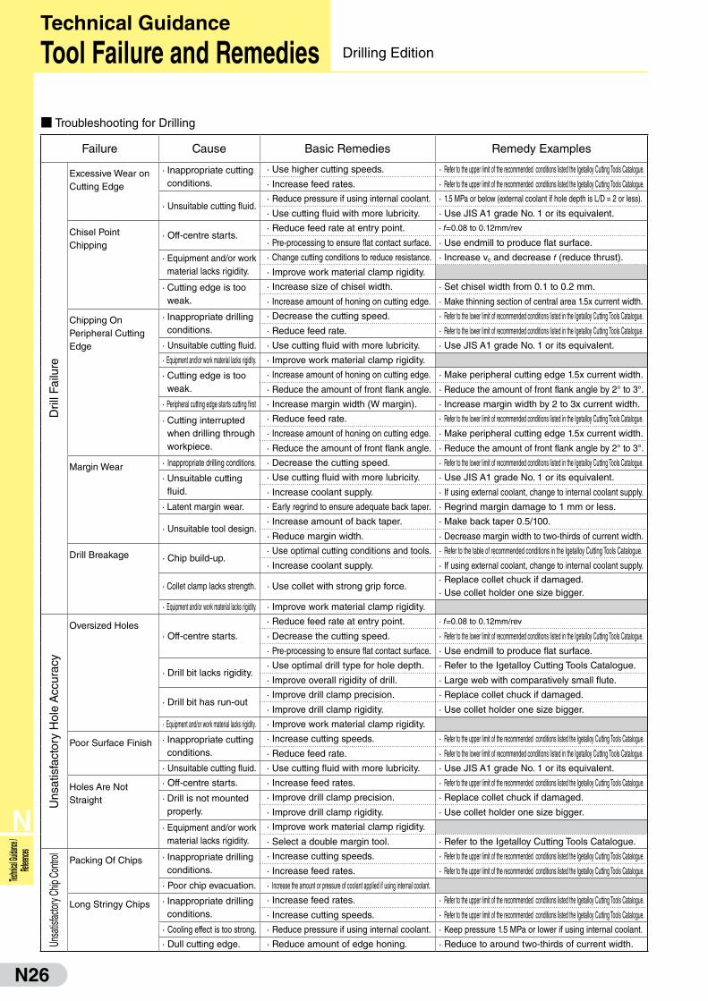
■ Troubleshooting for Drilling
Failure Cause Basic Remedies Remedy Examples
Dril
l Fai
lure
Excessive Wear on Cutting Edge
· Inappropriate cutting conditions.
· Use higher cutting speeds. · Refer to the upper limit of the recommended conditions listed the Igetalloy Cutting Tools Catalogue.
· Increase feed rates. · Refer to the upper limit of the recommended conditions listed the Igetalloy Cutting Tools Catalogue.
· Unsuitable cutting fluid.· Reduce pressure if using internal coolant. · 1.5 MPa or below (external coolant if hole depth is L/D = 2 or less).
· Use cutting fluid with more lubricity. · Use JIS A1 grade No. 1 or its equivalent.
Chisel Point Chipping
· Off-centre starts.· Reduce feed rate at entry point. · f=0.08 to 0.12mm/rev
· Pre-processing to ensure flat contact surface. · Use endmill to produce flat surface.
· Equipment and/or work material lacks rigidity.
· Change cutting conditions to reduce resistance. · Increase vc and decrease f (reduce thrust).
· Improve work material clamp rigidity.
· Cutting edge is too weak.
· Increase size of chisel width. · Set chisel width from 0.1 to 0.2 mm.
· Increase amount of honing on cutting edge. · Make thinning section of central area 1.5x current width.
Chipping On Peripheral Cutting Edge
· Inappropriate drilling conditions.
· Decrease the cutting speed. · Refer to the lower limit of recommended conditions listed in the Igetalloy Cutting Tools Catalogue.
· Reduce feed rate. · Refer to the lower limit of recommended conditions listed in the Igetalloy Cutting Tools Catalogue.
· Unsuitable cutting fluid. · Use cutting fluid with more lubricity. · Use JIS A1 grade No. 1 or its equivalent.
· Equipment and/or work material lacks rigidity. · Improve work material clamp rigidity.
· Cutting edge is too weak.
· Increase amount of honing on cutting edge. · Make peripheral cutting edge 1.5x current width.
· Reduce the amount of front flank angle. · Reduce the amount of front flank angle by 2° to 3°.
· Peripheral cutting edge starts cutting first · Increase margin width (W margin). · Increase margin width by 2 to 3x current width.
· Cutting interrupted when drilling through workpiece.
· Reduce feed rate. · Refer to the lower limit of recommended conditions listed in the Igetalloy Cutting Tools Catalogue.
· Increase amount of honing on cutting edge. · Make peripheral cutting edge 1.5x current width.
· Reduce the amount of front flank angle. · Reduce the amount of front flank angle by 2° to 3°.
Margin Wear · Inappropriate drilling conditions. · Decrease the cutting speed. · Refer to the lower limit of recommended conditions listed in the Igetalloy Cutting Tools Catalogue.
· Unsuitable cutting fluid.
· Use cutting fluid with more lubricity. · Use JIS A1 grade No. 1 or its equivalent.
· Increase coolant supply. · If using external coolant, change to internal coolant supply.
· Latent margin wear. · Early regrind to ensure adequate back taper. · Regrind margin damage to 1 mm or less.
· Unsuitable tool design.· Increase amount of back taper. · Make back taper 0.5/100.
· Reduce margin width. · Decrease margin width to two-thirds of current width.
Drill Breakage · Chip build-up.· Use optimal cutting conditions and tools. · Refer to the table of recommended conditions in the Igetalloy Cutting Tools Catalogue.
· Increase coolant supply. · If using external coolant, change to internal coolant supply.
· Collet clamp lacks strength. · Use collet with strong grip force.· Replace collet chuck if damaged.· Use collet holder one size bigger.
· Equipment and/or work material lacks rigidity. · Improve work material clamp rigidity.
Uns
atis
fact
ory
Hol
e A
ccur
acy
Oversized Holes· Off-centre starts.
· Reduce feed rate at entry point. · f=0.08 to 0.12mm/rev
· Decrease the cutting speed. · Refer to the lower limit of recommended conditions listed in the Igetalloy Cutting Tools Catalogue.
· Pre-processing to ensure flat contact surface. · Use endmill to produce flat surface.
· Drill bit lacks rigidity.· Use optimal drill type for hole depth. · Refer to the Igetalloy Cutting Tools Catalogue.
· Improve overall rigidity of drill. · Large web with comparatively small flute.
· Drill bit has run-out· Improve drill clamp precision. · Replace collet chuck if damaged.
· Improve drill clamp rigidity. · Use collet holder one size bigger.
· Equipment and/or work material lacks rigidity. · Improve work material clamp rigidity.
Poor Surface Finish · Inappropriate cutting conditions.
· Increase cutting speeds. · Refer to the upper limit of the recommended conditions listed the Igetalloy Cutting Tools Catalogue.
· Reduce feed rate. · Refer to the lower limit of recommended conditions listed in the Igetalloy Cutting Tools Catalogue.
· Unsuitable cutting fluid. · Use cutting fluid with more lubricity. · Use JIS A1 grade No. 1 or its equivalent.
Holes Are Not Straight
· Off-centre starts. · Increase feed rates. · Refer to the upper limit of the recommended conditions listed the Igetalloy Cutting Tools Catalogue.
· Drill is not mounted properly.
· Improve drill clamp precision. · Replace collet chuck if damaged.
· Improve drill clamp rigidity. · Use collet holder one size bigger.
· Equipment and/or work material lacks rigidity.
· Improve work material clamp rigidity.
· Select a double margin tool. · Refer to the Igetalloy Cutting Tools Catalogue.
Unsa
tisfac
tory C
hip C
ontro
l
Packing Of Chips · Inappropriate drilling conditions.
· Increase cutting speeds. · Refer to the upper limit of the recommended conditions listed the Igetalloy Cutting Tools Catalogue.
· Increase feed rates. · Refer to the upper limit of the recommended conditions listed the Igetalloy Cutting Tools Catalogue.
· Poor chip evacuation. · Increase the amount or pressure of coolant applied if using internal coolant.
Long Stringy Chips · Inappropriate drilling conditions.
· Increase feed rates. · Refer to the upper limit of the recommended conditions listed the Igetalloy Cutting Tools Catalogue.
· Increase cutting speeds. · Refer to the upper limit of the recommended conditions listed the Igetalloy Cutting Tools Catalogue.
· Cooling effect is too strong. · Reduce pressure if using internal coolant. · Keep pressure 1.5 MPa or lower if using internal coolant.
· Dull cutting edge. · Reduce amount of edge honing. · Reduce to around two-thirds of current width.
Technical Guidance
Tool Failure and Remedies Drilling Edition

N27
N
Technical Guidance / References
■ Application Map of the Various Tool Materials
■ Work Materials and their Cutting Speed Recommendations
300
100
200
Carburised or Induction Hardened Material Bearing Steel Die Steel
Prone to notch wear Wear fairly large Wear large
Cut
ting
Spe
ed (
m/m
in)
■ Influence of Coolant on Tool Life
20
0.3
0.25
0.2
0.15
0.1
0.05
040 60 80 100 120 140
Cutting Time (min)
DRYOil-base coolantWater soluble emulsionWater soluble
☆ In continuous cutting of bearing steel, there is not much difference in dry or wet cut.
Fla
nk W
ear W
idth
VB (
mm
)
0
50
100
DRY
Interrupted Cutting
Heavy
Wet
Tool
Life
■ Relation Between Work Material Hardness and Cutting Force
■ Relation Between Flank Wear and Cutting Force
0.05
300
200
100
0
100
0100
00.10
Back
For
ce (N
)Pr
incip
al F
orce
(N)
Feed
For
ce (N
)
Flank Wear Width VB (mm)
SCM43065HRC
S55C24HRC
■ Influence of Work Material Hardness on Cutting Force and Accuracy
45(HS)
106N
90
70
50
30
400
300
200
13µm0
-10
-20
Hard zone
Hard zone
Soft zone
Work: S38C
Sho
re H
ardn
ess
(HS
)B
ack
Forc
e (N
)D
imen
sion
(μm
)
■ Improvement of Surface Roughness by Altering the Feed RateConstant Feed Rate Variable Feed Rate
f
Stationary Notch Location
Previous edge position f
Shifting Notch Location
☆ Varying the feed rate spreads the notch location over a larger area. → Surface finish improves and notch wear decreases.
■ Relation Between Cutting Speed and Surface Roughness
400 80 120 1600
0.1
0.2
0.3
Sur
face
Rou
ghne
ss R
a (μ
m)
Machining Output (pcs.)
BN250 V=120BN250 V=150BN250 V=180
Work: SCM420H 58 to 62HRC
Holder: MTXNR2525Insert: NU–TNMA160408
Conditions: vc= 120, 150, 180 m/min f = 0.045mm/rev ap= 0.15mm
Wet
At high cutting speeds, surface roughness is more stable.
Feed force
Principal force
Back force
10
150
100
50
030 50 70
Principal forceFeed forceBack force
Hardness of Work Material (HRC)
Cut
ting
For
ce (
N)
Condition: C/speed vc =80m/minD.O.C ap=0.15mm Feed rate f =0.1mm/rev
For hardened steel machining, back force increases substantially due to the expansion of flank wear.
External dimension at the soft zone is smaller due to lower cutting forces.
Work: SUJ2(58 to 62HRC)Condition: TPGN160304vc=100m/min ap=0.15mm f =0.1mm/rev Continuous cutting
For continuous cutting, the influence of coolant on tool life is minimal. However, for interrupted cutting, coolant will shorten the tool life because of thermal cracking.
Back force increases substantially for harder work materials.
Work :Conditions :
40 45 50 55 60 65Hardness of Work Material (HRC)
Heavy
Light
Coated carbide cermet SUMIBORON
Ceramic
Inte
rrup
ted
Cut
ting
Con
tinuo
usC
uttin
g
SKD11–4U SlottingCutting speed vc=100m/min.D.O.C ap=0.2mmFeed rate f =0.1mm/rev
● Continuous Cutting ● Interrupted Cutting
SK 3C/speed vc=120m/min.D.O.C ap=0.2mm.Feed rate f =0.1mm/rev
Cutting Speed :Depth of Cut :Feed rate :
vc=120m/minap=0.5mm f = 0.3mm/rev Dry
Technical Guidance
Hardened Steel Machining with SUMIBORONSUMIBORON Edition

N28
N
Technic
al Guida
nce /
Referen
ces
■ Advantages of Using SUMIBORON for Cast Iron Machining
■ Milling
● Higher Accuracy ● Longer Tool Life at Higher Cutting Speeds
・High speed machining vc=2,000m/min・Surface Roughness 3.2Rz (1.0Ra)
・ Running cost is reduced because of economical insert.
・�Easy insert setting with the aid of a setting gauge.
・�Employs safe, anti-centrifugal force construction for high-speed conditions.
SUMIBORON BN Finish Mill EASY
■ Turning ● Cast Iron Structure and Wear Shape Examples
Structure
FC FCD
Matrix Pearlite Pearlite + Ferrite
Tool
Wea
r S
hape Wet
Dry
(vc = 200 to 500m/min)
DRY
10
8
6
4
2
0200 400
Sur
face
Rou
ghne
ss R
max
(μm
)
Cutting Speed vC (m/min)
2.5 5 7.5 10 12.50
0.1
0.2
0.3
0.4DryWET (Water soluble)
Cutting Length (km)
Fla
nk W
ear W
idth
VB (
mm
)
Crater wear
0 20 40 60 80 100 120 140 160 180 200
0.25
0.20
0.15
0.10
0.05
0.0
vc=600m/min
vc=600m/min vc=1,000m/min
vc=1,500m/min
CeramicCeramicvc=400m/min
Number of Passes (Pass)
Fla
nk W
ear
wid
th (
mm
)
3000
50
100
150
200
250
450 600 750 900 1,050 1,200 1,350 1,500
Dry
Wet
Cutting Conditionsap=0.5mm fz=0.15mm/t
Num
ber
of P
asse
s (P
ass)
Cutting Speed (m/min)
Technical Guidance
High Speed Machining of Cast Iron withs SUMIBORON SUMIBORON Edition
0.4 0.8 1.6 3.2
BNS800BN7000BNC500
CeramicCoated CarbideCermet
Goo
d
→ Siz
e A
ccur
acy
Good ← Surface Roughness Ra (μm)
1,000
500
200
1 10 20
BNS800BN7000BNC500
Tool Life Ratio
Grey Cast Iron
CeramicCoated CarbideCermet
Cut
ting
Spe
ed (
m/m
in)
500
200
1 10
BNX10
BNC500
BN7000
Ductile Cast Iron
CeramicCoated CarbideCermet
Cut
ting
Spe
ed (
m/m
in)
Tool Life Ratio
Work : FC250 Continuous cuttingTool material : BN500Tool Shape : SNGN120408Conditions : vc=450m/min
ap=0.25mmf =0.15mm/revDry&Wet (water soluble)
Machine : N/C latheWork : FC250 200HBHolder : MTJNP2525Tool material : BN500Tool Shape : TNMA160408Conditions : vc=110 to 280m/min
f =0.1mm/rev ap=0.1mm Wet
For machining cast iron with SUMIBORON, cutting speeds (vc) should be 200m/min and above. WET cutting is recommended.
WET(Water soluble)
Dry cutting is recommended for high speed milling of cast iron with SUMIBORON. (Conditions)・Work: FC250・Condition: ap =0.5mm fz =0.1mm/t Dry・Tool material: BN7000
Thermal cracks occur.

N29
N
Technical Guidance / References
■ Powder Metal
■ Heat Resistive Alloy● Ni Based Alloy
■ Hard Facing Alloys
BNS800(vc =300m/min, After 2km of cutting)
Whisker Reinforced Ceramic(vc =50m/min, After 10m of cutting)
BNS800
(After 2km of cutting)
★ Influences of cutting speed (Grade BNX20, f =0.06mm/rev, L=0.72km)
vc =300m/min vc =500m/min
★ Influences of feed rate (Grade BNX20, vc=300m/min, L=0.18km)
f =0.12 mm/rev f =0.06 mm/rev
★ Influence of tool grade (vc=500m/min, f =0.12 mm/rev. L=0.36km)
BNX20 BN7000
Typical tool damage of CBN tool when cutting Inconel 718
12
0 50 100
10
8
6
4
2
150 200
0.1
0 50 100
0.2
0.3
0.4
0.5
150 200 0 50 100
0.7
0.6
0.5
0.4
0.3
0.2
0.1
150 200
■
■
■■
D D
D
DD
D
DD
■ ■
■
D D DD
DDDD
■■
DD
D
D
D DD D
Fla
nk W
ear W
idth
(m
m)
Cutting Speed (m/min) Cutting Speed (m/min)
Sur
face
Rou
ghne
ss R
z (μ
m)
Max
Hei
ght o
f Bur
r (m
m)
Cutting Speed (m/min)
Flank Wear
Notch wear
Flank Wear
Notch wear Flank Wear
Notch wear Flank Wear
0 500 1000 1500 2000
600
500
400
300
200
100
0
BN700
BNX20
Whisker Reinforced Ceramic
Cut
ting
Spe
ed (
m/m
in)
Cutting Length (m)0 1000 2000 3000
600
500
400
300
200
100
0
BN700
BNX20
Whisker Reinforced Ceramic
Coated carbide (K series)
Cut
ting
Spe
ed (
m/m
in)
Cutting Length (m)
● Ti Based Alloy
Work: Ti–6A–4VInsert: NF–DNMX120404Cutting Conditions: vc =100m/min. ap =0.1mm f =0.05mm/rev Wet
☆ SUMIDIA positive type inserts are extremely good for Ti Alloy, due to high cutting edge strength and high wear resistance.
Work: Ti–6A–4VInsert: NF–DNMX120404Cutting Conditions: vc =100m/min. ap =0.1mm f =0.05mm/rev Wet
☆ SUMIDIA positive type inserts are extremely good for Ti alloy, due to high cutting edge strength and high wear resistance.
Work: Ti–6AI–4VTool: DNMA150412Cutting Conditions: vc =120m/min. ap =0.3mm f =0.25mm/rev Wet
☆ Highly fracture resistant BN7000 negative insert is suitable for high-efficiency machining with a large depth-of-cut and a high feed rate.
200
0.20
0.15
0.10
0.05
040 60
BN7000DA150 Breakage
Fla
nk W
ear W
idth
VB (
mm
)
Cutting Time (min.)50
0.12
0.10
0.08
0.06
0.04
0.02
010 15
BN700 Breakage
Fla
nk W
ear W
idth
VB (
mm
)
Cutting Time (min.)
DA150
K10
50
0.12
0.10
0.08
0.06
0.04
0.02
010 15
DA150
BN700 Breakage
Fla
nk W
ear W
idth
VB (
mm
)
Cutting Time (min.)
K10
0.20 0.4 0.6 0.8 1.0 1.20
0.1
0.2
0.3
0.4
0.5
BNS800 (vc=300m/min)
Whisker reinforced ceramic (vc=50m/min)
Cutting is difficult
because of large wear at
vc=50m/min
Small wear at vc=300m/min
Fla
nk W
ear W
idth
(m
m)
Cutting Length (km)
Comp.'s solid CBN
(After 2km of cutting)
Chipping
0.50 1.0 2.01.5 2.50
0.02
0.04
0.06
0.08
0.10
BNS800
Comp.’s solid CBN
Chipping
No chipping
Fla
nk W
ear W
idth
(m
m)
Cutting Length (km)
0.5mm
Technical Guidance
Machining Hard-to-cut Materials with SUMIBORONSUMIBORON Edition
D ■ DSUMIBORON Carbide Cermet
1. Flank Wear 2. Surface Roughness 3. Height of Burr
Work: SMF4040 equivalent, Process details: ø80-ø100mm heavy interrupted facing with grooves and drilled holes. (After 40 passes)
Cutting Conditions: f=0.1mm/rev, ap=0.1mm, WetInsert: TNGA160404
For general powder metal components, carbide and cermet grades can perform up to vc=100m/min. However, around vc=120m/minSUMIBORON, on the other hand, exhibits stability and superior wear resistance, burr prevention and surface roughness especially at high speeds.
Conditions: f=0.06mm/rev, ap=0.3mm, Wet Conditions: f=0.12mm/rev, ap=0.3mm, Wet
Tool life criteriaNotch wear = 0.25mm (○)Or flank wear = 0.25mmBNX20 is recommended for high speed and low feed ratesBN700 is recommended for cutting speeds below vc=240m/min.
Tool life criteriaNotch wear = 0.25mm (○)Or flank wear = 0.25mmBN700 is recommended for cutting at high feed rates. (Over f =0.1mm/rev)
Work: Colmonoy No.6 (NiCr-based self-fluxing alloy)
Insert : SNGN0 90308Cutting Conditions : vc = 50,300m/min
f = 0.1mm/revap = 0.2mmDry
Work: Stellite SF-20 (Co-based self-fluxing alloy)
Insert : SNGN090308Cutting Conditions : vc = 50m/min
f = 0.1mm/revap = 0.2mmDry
Conditions: ap= 0.3mm, Wet
N30
N
Technic
al Guida
nce /
Referen
ces
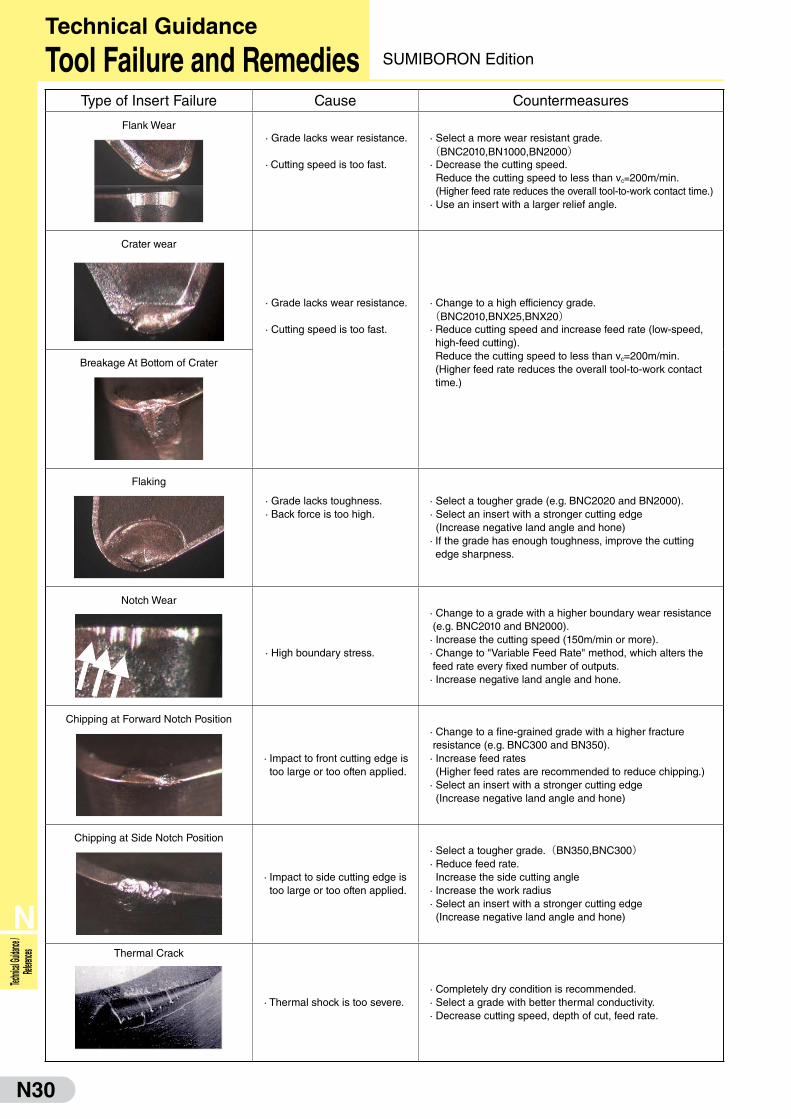
Type of Insert Failure Cause Countermeasures
Flank Wear · Grade lacks wear resistance.
· Cutting speed is too fast.
· Select a more wear resistant grade.(BNC2010,BN1000,BN2000)· Decrease the cutting speed. Reduce the cutting speed to less than vc=200m/min. (Higher feed rate reduces the overall tool-to-work contact time.)· Use an insert with a larger relief angle.
Crater wear
· Grade lacks wear resistance.
· Cutting speed is too fast.
· Change to a high efficiency grade.(BNC2010,BNX25,BNX20)· Reduce cutting speed and increase feed rate (low-speed, high-feed cutting). Reduce the cutting speed to less than vc=200m/min.(Higher feed rate reduces the overall tool-to-work contact time.)
Breakage At Bottom of Crater
Flaking
· Grade lacks toughness. · Back force is too high.
· Select a tougher grade (e.g. BNC2020 and BN2000).· Select an insert with a stronger cutting edge (Increase negative land angle and hone)· If the grade has enough toughness, improve the cutting edge sharpness.
Notch Wear
· High boundary stress.
· Change to a grade with a higher boundary wear resistance (e.g. BNC2010 and BN2000).· Increase the cutting speed (150m/min or more).· Change to "Variable Feed Rate" method, which alters the feed rate every fixed number of outputs.· Increase negative land angle and hone.
Chipping at Forward Notch Position
· Impact to front cutting edge is too large or too often applied.
· Change to a fine-grained grade with a higher fracture resistance (e.g. BNC300 and BN350).· Increase feed rates (Higher feed rates are recommended to reduce chipping.)· Select an insert with a stronger cutting edge (Increase negative land angle and hone)
Chipping at Side Notch Position
· Impact to side cutting edge is too large or too often applied.
· Select a tougher grade.(BN350,BNC300)· Reduce feed rate. Increase the side cutting angle· Increase the work radius· Select an insert with a stronger cutting edge (Increase negative land angle and hone)
Thermal Crack
· Thermal shock is too severe.· Completely dry condition is recommended.· Select a grade with better thermal conductivity.· Decrease cutting speed, depth of cut, feed rate.
Technical Guidance Tool Failure and Remedies SUMIBORON Edition
N31
N
Technical Guidance / References
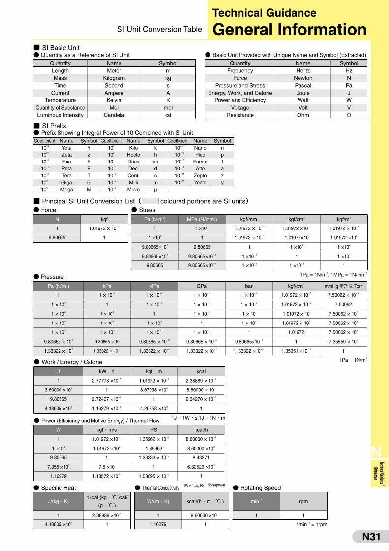
■ SI Basic Unit● Quantity as a Reference of SI Unit
Quantity Name SymbolLength Meter mMass Kilogram kgTime Second s
Current Ampere ATemperature Kelvin K
Quantity of Substance Mol molLuminous Intensity Candela cd
● Basic Unit Provided with Unique Name and Symbol (Extracted)Quantity Name Symbol
Frequency Hertz HzForce Newton N
Pressure and Stress Pascal PaEnergy, Work, and Calorie Joule J
Power and Efficiency Watt WVoltage Volt V
Resistance Ohm Ω
■ SI Prefix● Prefix Showing Integral Power of 10 Combined with SI UnitCoefficient Name Symbol Coefficient Name Symbol Coefficient Name Symbol
1024 Yota Y 103 Kilo k 10-9 Nano n1021 Zeta Z 102 Hecto h 10-12 Pico p1018 Exa E 101 Deca da 10-15 Femto f1015 Peta P 10-1 Deci d 10-18 Atto a1012 Tera T 10-2 Centi c 10-21 Zepto z109 Giga G 10-3 Milli m 10-24 Yocto y106 Mega M 10-6 Micro μ
● Specific Heat
J/(kg・K)1kcal (kg・℃ )cal/
(g・℃ )
1 2.38889 ×10⁻⁴
4.18605 ×10³ 1
● Thermal Conductivity
W/(m・K) kcal/(h・m・℃ )
1 8.60000 ×10⁻¹
1.16279 1
● Rotating Speed
min-1 rpm
1 1
1min-1 = 1rpm
● Power (Efficiency and Motive Energy) / Thermal Flow
W kgf・m/s PS kcal/h
1 1.01972 ×10⁻¹ 1.35962 × 10⁻³ 8.60000 × 10⁻¹
1 ×10³ 1.01972 ×10² 1.35962 8.60000 ×10²
9.80665 1 1.33333 × 10⁻² 8.43371
7.355 ×10² 7.5 ×10 1 6.32529 ×10²
1.16279 1.18572 ×10⁻¹ 1.58095 × 10⁻³ 1
1W = 1J/s, PS:Horsepower
● Work / Energy / Calorie
J kW・h kgf・m kcal
1 2.77778 ×10⁻⁷ 1.01972 × 10⁻¹ 2.38889 × 10⁻⁴
3.60000 ×10⁶ 1 3.67098 ×10⁵ 8.60000 × 10²
9.80665 2.72407 ×10⁻⁶ 1 2.34270 × 10⁻³
4.18605 ×10³ 1.16279 ×10⁻³ 4.26858 ×10² 1
1J = 1W・s,1J = 1N ・ m
● Pressure
Pa (N/m2) kPa MPa GPa bar kgf/cm2 mmHgまたは Torr
1 1 × 10⁻³ 1 × 10⁻⁶ 1 × 10⁻⁹ 1 × 10⁻⁵ 1.01972 × 10⁻⁵ 7.50062 × 10⁻³
1 × 10³ 1 1 × 10⁻³ 1 × 10⁻⁶ 1 × 10⁻² 1.01972 × 10⁻² 7.50062
1 × 10⁶ 1 × 10³ 1 1 × 10⁻³ 1 × 10 1.01972 × 10 7.50062 × 10³
1 × 10⁹ 1 × 10⁶ 1 × 10³ 1 1 × 10⁴ 1.01972 × 10⁴ 7.50062 × 10⁶
1 × 10⁵ 1 × 10² 1 × 10⁻¹ 1 × 10⁻⁴ 1 1.01972 7.50062 × 10²
9.80665 × 10⁴ 9.80665 × 10 9.80665 × 10⁻² 9.80665 × 10⁻⁵ 9.80665×10⁻¹ 1 7.35559 × 10²
1.33322 × 10² 1.33322 × 10⁻¹ 1.33322 × 10⁻⁴ 1.33322 × 10⁻⁷ 1.33322 ×10⁻³ 1.35951 ×10- 3 1
1Pa = 1N/m2
● Stress
Pa (N/m2) MPa (N/mm2) kgf/mm2 kgf/cm2 kgf/m2
1 1 ×10⁻⁶ 1.01972 × 10⁻⁷ 1.01972 ×10⁻⁵ 1.01972 × 10⁻¹
1 ×10⁶ 1 1.01972 × 10⁻¹ 1.01972×10 1.01972 ×10⁵
9.80665×10⁶ 9.80665 1 1 ×10² 1 ×10⁶
9.80665×10⁴ 9.80665×10⁻² 1 ×10⁻² 1 1 ×10⁴
9.80665 9.80665×10⁻⁶ 1 ×10⁻⁶ 1 ×10⁻⁴ 1
1Pa = 1N/m2, 1MPa = 1N/mm2
■ Principal SI Unit Conversion List( coloured portions are SI units)● Force
N kgf
1 1.01972 × 10⁻¹
9.80665 1
Technical Guidance General InformationSI Unit Conversion Table
N32
N
Technic
al Guida
nce /
Referen
ces
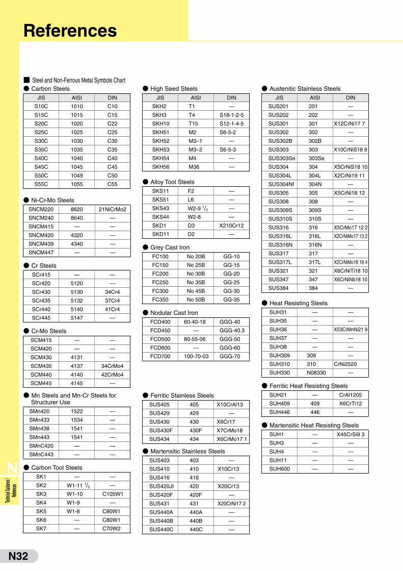
■ Steel and Non-Ferrous Metal Symbols Chart● Carbon Steels
JIS AISI DIN
S10C 1010 C10
S15C 1015 C15
S20C 1020 C22
S25C 1025 C25
S30C 1030 C30
S35C 1035 C35
S40C 1040 C40
S45C 1045 C45
S50C 1049 C50
S55C 1055 C55
● High Seed Steels
JIS AISI DIN
SKH2 T1 —
SKH3 T4 S18-1-2-5
SKH10 T15 S12-1-4-5
SKH51 M2 S6-5-2
SKH52 M3–1 —
SKH53 M3–2 S6-5-3
SKH54 M4 —
SKH56 M36 —
● Austenitic Stainless Steels
JIS AISI DIN
SUS201 201 —
SUS202 202 —
SUS301 301 X12CrNi17 7
SUS302 302 —
SUS302B 302B —
SUS303 303 X10CrNiS18 9
SUS303Se 303Se —
SUS304 304 X5CrNiS18 10
SUS304L 304L X2CrNi19 11
SUS304NI 304N —
SUS305 305 X5CrNi18 12
SUS308 308 —
SUS309S 309S —
SUS310S 310S —
SUS316 316 X5CrMo17 12 2
SUS316L 316L X2CrNiMo17 13 2
SUS316N 316N —
SUS317 317 —
SUS317L 317L X2CrNiMo18 16 4
SUS321 321 X6CrNiTi18 10
SUS347 347 X6CrNiNb18 10
SUS384 384 —
● Ni-Cr-Mo Steels
SNCM220 8620 21NiCrMo2
SNCM240 8640 —
SNCM415 — —
SNCM420 4320 —
SNCM439 4340 —
SNCM447 — —
● Cr Steels
SCr415 — —
SCr420 5120 —
SCr430 5130 34Cr4
SCr435 5132 37Cr4
SCr440 5140 41Cr4
SCr445 5147 —
● Cr-Mo Steels
SCM415 — —
SCM420 — —
SCM430 4131 —
SCM435 4137 34CrMo4
SCM440 4140 42CrMo4
SCM445 4145 —
● Mn Steels and Mn-Cr Steels for Structurer Use
SMn420 1522 —
SMn433 1534 —
SMn438 1541 —
SMn443 1541 —
SMnC420 — —
SMnC443 — —
● Carbon Tool Steels
SK1 — —
SK2 W1-11 1/2 —
SK3 W1-10 C105W1
SK4 W1-9 —
SK5 W1-8 C80W1
SK6 — C80W1
SK7 — C70W2
● Alloy Tool Steels
SKS11 F2 —
SKS51 L6 —
SKS43 W2-9 1/2 —
SKS44 W2-8 —
SKD1 D3 X210Cr12
SKD11 D2 —
● Grey Cast Iron
FC100 No 20B GG-10
FC150 No 25B GG-15
FC200 No 30B GG-20
FC250 No 35B GG-25
FC300 No 45B GG-30
FC350 No 50B GG-35
● Nodular Cast Iron
FCD400 60-40-18 GGG-40
FCD450 — GGG-40.3
FCD500 80-55-06 GGG-50
FCD600 — GGG-60
FCD700 100-70-03 GGG-70
● Ferritic Stainless Steels
SUS405 405 X10CrAl13
SUS429 429 —
SUS430 430 X6Cr17
SUS430F 430F X7CrMo18
SUS434 434 X6CrMo17 1
● Martensitic Stainless Steels
SUS403 403 —
SUS410 410 X10Cr13
SUS416 416 —
SUS420JI 420 X20Cr13
SUS420F 420F —
SUS431 431 X20CrNi17 2
SUS440A 440A —
SUS440B 440B —
SUS440C 440C —
● Heat Resisting Steels
SUH31 — —
SUH35 — —
SUH36 — X53CrMnNi21 9
SUH37 — —
SUH38 — —
SUH309 309 —
SUH310 310 CrNi2520
SUH330 N08330 —
● Ferritic Heat Resisting Steels
SUH21 — CrAl1205
SUH409 409 X6CrTi12
SUH446 446 —
● Martensitic Heat Resisting Steels
SUH1 — X45CrSi9 3
SUH3 — —
SUH4 — —
SUH11 — —
SUH600 — —
References

N33
N
Technical Guidance / References
■ Steel and Non-Ferrous Metal Symbols Chart● Classifications and Symbols of Steels
Class Material Symbol Code Description
Stru
ctur
al S
teel
s Rolled Steels for welded structures SM "M" for "Marine"-Usually used in welded marine structures
Re-rolled Steels SRB "R" for "Re-rolled" and "B" for "Bar"
Rolled Steels for general structures SS S for "Steel" and for "Structure"
Light gauge sections for general structures SSC C for "Cold"
Steel Sheets Hot rolled mild steel sheets / plates in coil form SPH P for "Plate" and "H" for "Hot"
Ste
el T
ubes
Carbon steel tubes for piping SGP "GP" for "Gas Pipe"
Carbon steel tubes for boiler and heat exchangers STB "T" for "Tube" and "B" for "Boiler"
Seamless steel tubes for high pressure gas cylinders STH "H" for "High Pressure"
Carbon steel tubes for general structures STK "K" for "Kozo"-Japanese word meaning "structure"
Carbon steel tubes for machine structural uses STKM "M" for "Machine"
Alloy steel tubes for structures STKS "S" for "Special"
Alloy steel tubes for piping STPA "P" for "Piping" and "A" for "Alloy"
Carbon steel tubes for pressure piping STPG "G" for "General"
Carbon steel tubes for high temperature piping STPT "T" for "Temperatures"
Carbon steel tubes for high pressure piping STS "S" after "SP" is abbreviation for "Special"
Stainless steel tubes for piping SUS-TP "T" for "Tube" and "P" for "Piping"
Stee
l for
Mac
hine
Stru
ctur
es Carbon steels for machine structural uses SxxC "C" for "Carbon"
Aluminium Chromium Molybdenum steels SACM "A" for "Al", "C" for "Cr" and "M" for "Mo"
Chromium Molybdenum steels SCM "C" for "Cr" and "M" for "Mo"
Chromium steels SCr "Cr" for "Chromium"
Nickel Chromium steels SNC "N" for "Nickel" and "C"for "Chromium"
Nickel Chromium Molybdenum steels SNCM "M" for "Molybdenum"Manganese steels for structural use Manganese Chromium steels
SMnSMnC
"Mn" for "Manganese""C" for "Chromium"
Spe
cial
Ste
els To
ol S
teel
s Carbon tool steels SK "K" for "Kogu"-Japanese word meaning "tool"
Hollow drill steels SKC "C" for "Chisel"
Alloy tool steelSKSSKDSKT
S for "Special"D for "Die"T for "Tanzo"-Japanese word for "forging"
High speed tool steels SKH "H" for "High speed"
Stai
nles
s St
eels Free cutting sulphuric steels SUM "M" for "Machinability"
High Carbon Chromium bearing steels SUJ "J" for "Jikuuke"-Japanese word meaning "bearing"
Spring steels SUP "P" for "Spring"
Stainless Steels SUS "S" after "SU" is abbreviation for "Stainless"
Heat-r
esista
nt Stee
ls
Heat-resistant steels SUH "U" for "Special Usage" and "H" for "Heat"
Heat-resistant steel bars SUH-B "B" for "Bar"
Heat-resistant steels sheets SUHP "P" for "Plate"
Forg
ed S
teel
s Carbon steel forgings for general use SF "F" for "Forging"
Carbon steel booms and billets for forgings SFB "B" for "Billet"
Chromium Molybdenum steel forgings SFCM "C" for "Chromium" and "M" for "Molybdenum"
Nickel Chromium Molybdenum steel forgings SFNCM "N" for "Nickel"
Cas
t Iro
ns
Grey cast irons FC "F" for "Ferrous" and "C" for "Casting"
Spherical graphite / Ductile cast irons FCD "D" for "Ductile"
Blackheart malleable cast irons FCMB "M" for "Malleable" and "B" for "Black"
Whiteheart malleable cast irons FCMW "W" for "White"
Pearlite malleable cast irons FCMP "P" for "Pearlite"
Cas
t Ste
els Carbon cast steels SC "C" for "Casting"
Stainless cast steels SCS "S" for "Stainless"
Heat-resistant cast steels SCH "H" for "Heat"
High Manganese cast steels SCMnH "Mn" for "Manganese" and "H" for "High"
● Non-Ferrous Metals
Class Material Symbol
Cop
per
and
Cop
per A
lloys
Copper and Copper alloys - Sheets, plates and strips
CxxxxP
CxxxxPP
CxxxxR
Copper and Copper alloys - Welded pipes and tubes
CxxxxBD
CxxxxBDS
CxxxxBE
CxxxxBF
Alu
min
ium
and
Alu
min
ium
Allo
ys Aluminium and Al alloys - Sheets, plates and strips
AxxxxP
AxxxxPC
Aluminium and Al alloys-Rods, bars, and wires
AxxxxBE
AxxxxBD
AxxxxW
Aluminium and Al alloys-Extruded shapes AxxxxS
Aluminium and Al alloys forgingsAxxxxFD
AxxxxFH
Magn
esium
Alloy
s
Magnesium alloy sheets and plates MP
Nic
kel
Allo
ys Nickel-copper alloy sheets and plates NCuP
Nickel-copper alloy rods and bars NCuBW
roug
htTi
tani
um
Titanium rods and bars TB
Cas
tings
Brass castings YBsCx
High strength Brass castings HBsCx
Bronze castings BCx
Phosphorus Bronze castings PBCx
Aluminium Bronze castings AlBCx
Aluminium alloy castings AC
Magnesium alloy castings MC
Zinc alloy die castings ZDCx
Aluminium alloy die castings ADC
Magnesium alloy die castings MDC
White metals WJ
Aluminium alloy castings for bearings AJ
Copper-Lead alloy castings for bearings KJ
References

N34
N
Technic
al Guida
nce /
Referen
ces
■ Hardness Scale Comparison Chart● Approximate Corresponding Values for Steel Hardness on the Brinell Scale
Brinell Hardness
3,000kgf
HB
Rockwell Hardness
Vickers Hardness
50kgf
HV
Shore Hardness
HS
Traverse RuptureStrength
(GPa)
AScale60kgfbralebraleHRA
BScale100kgf1/10in
BallHRB
CScale150kgfbralebraleHRC
DScale100kgfbralebraleHRD
— 85.6 — 68.0 76.9 940 97 —
— 85.3 — 67.5 76.5 920 96 —
— 85.0 — 67.0 76.1 900 95 —
767 84.7 — 66.4 75.7 880 93 —
757 84.4 — 65.9 75.3 860 92 —
745 84.1 — 65.3 74.8 840 91 —
733 83.8 — 64.7 74.3 820 90 —
722 83.4 — 64.0 73.8 800 88 —
712 — — — — — — —
710 83.0 — 63.3 73.3 780 87 —
698 82.6 — 62.5 72.6 760 86 —
684 82.2 — 61.8 72.1 740 — —
682 82.2 — 61.7 72.0 737 84 —
670 81.8 — 61.0 71.5 720 83 —
656 81.3 — 60.1 70.8 700 — —
653 81.2 — 60.0 70.7 697 81 —
647 81.1 — 59.7 70.5 690 — —
638 80.8 — 59.2 70.1 680 80 —
630 80.6 — 58.8 69.8 670 — —
627 80.5 — 58.7 69.7 667 79 —
601 79.8 — 57.3 68.7 640 77 —
578 79.1 — 56.0 67.7 615 75 —
555 78.4 — 54.7 66.7 591 73 2.06
534 77.8 — 53.5 65.8 569 71 1.98
514 76.9 — 52.1 64.7 547 70 1.89
495 76.3 — 51.0 63.8 528 68 1.82
477 75.6 — 49.6 62.7 508 66 1.73
461 74.9 — 48.5 61.7 491 65 1.67
444 74.2 — 47.1 60.8 472 63 1.59
429 73.4 — 45.7 59.7 455 61 1.51
415 72.8 — 44.5 58.8 440 59 1.46
401 72.0 — 43.1 57.8 425 58 1.39
388 71.4 — 41.8 56.8 410 56 1.33
375 70.6 — 40.4 55.7 396 54 1.26
363 70.0 — 39.1 54.6 383 52 1.22
352 69.3 (110.0) 37.9 53.8 372 51 1.18
341 68.7 (109.0) 36.6 52.8 360 50 1.13
331 68.1 (108.5) 35.5 51.9 350 48 1.10
Brinell Hardness
3,000kgf
HB
Rockwell Hardness
Vickers Hardness
50kgf
HV
Shore Hardness
HS
Traverse RuptureStrength
(GPa)
AScale60kgfbralebraleHRA
BScale100kgf1/10in
BallHRB
CScale150kgfbralebraleHRC
DScale100kgfbralebraleHRD
321 67.5 (108.0) 34.3 50.1 339 47 1.06
311 66.9 (107.5) 33.1 50.0 328 46 1.03
302 66.3 (107.0) 32.1 49.3 319 45 1.01
293 65.7 (106.0) 30.9 48.3 309 43 0.97
285 65.3 (105.5) 29.9 47.6 301 — 0.95
277 64.6 (104.5) 28.8 46.7 292 41 0.92
269 64.1 (104.0) 27.6 45.9 284 40 0.89
262 63.6 (103.0) 26.6 45.0 276 39 0.87
255 63.0 (102.0) 25.4 44.2 269 38 0.84
248 62.5 (101.0) 24.2 43.2 261 37 0.82
241 61.8 100.0 22.8 42.0 253 36 0.80
235 61.4 99.0 21.7 41.4 247 35 0.78
229 60.8 98.2 20.5 40.5 241 34 0.76
223 — 97.3 (18.8) — 234 — —
217 — 96.4 (17.5) — 228 33 0.73
212 — 95.5 (16.0) — 222 — 0.71
207 — 94.6 (15.2) — 218 32 0.69
201 — 93.8 (13.8) — 212 31 0.68
197 — 92.8 (12.7) — 207 30 0.66
192 — 91.9 (11.5) — 202 29 0.64
187 — 90.7 (10.0) — 196 — 0.62
183 — 90.0 (9.0) — 192 28 0.62
179 — 89.0 (8.0) — 188 27 0.60
174 — 87.8 (6.4) — 182 — 0.59
170 — 86.8 (5.4) — 178 26 0.57
167 — 86.0 (4.4) — 175 — 0.56
163 — 85.0 (3.3) — 171 25 0.55
156 — 82.9 (0.9) — 163 — 0.52
149 — 80.8 — — 156 23 0.50
143 — 78.7 — — 150 22 0.49
137 — 76.4 — — 143 21 0.46
131 — 74.0 — — 137 — 0.45
126 — 72.0 — — 132 20 0.43
121 — 69.8 — — 127 19 0.41
116 — 67.6 — — 122 18 0.40
111 — 65.7 — — 117 15 0.38
1) Figures within the ( ) are not commonly used2) Rockwell A, C and D scales utilise a diamond brale3) This chart was taken from the JIS Iron and Steel Handbook (1980)
References

N35
N
Technical Guidance / References
■ Standard of Tapers
● Morse Taper
● Bottle Grip Taper
● Bottle Grip Taper (Units: mm)
Taper No.D
(Standard)D1 D2 t1 t2 t3 t4 t5 d2 d3 L B L3 L4 g b1 t7 Fig
BT30 31.75 46 38 20 8 13.6 2 2 14 12.5 48.4 24 7 17 M12 16.1 16.3
3
BT35 38.10 53 43 22 10 14.6 2 2 14 12.5 56.4 24 7 20 M12 16.1 19.6
BT40 44.45 63 53 25 10 16.6 2 2 19 17 65.4 30 8 21 M16 16.1 22.6
BT45 57.15 85 73 30 12 21.2 3 3 23 21 82.8 36 9 26 M20 19.3 29.1
BT50 69.85 100 85 35 15 23.2 3 3 27 25 101.8 45 11 31 M24 25.7 35.4
BT60 107.95 155 135 45 20 28.2 3 3 33 31 161.8 56 12 34 M30 25.7 60.1
(Units: mm)
MorseTaper
NumberTaper(1)
TaperAngle(E)
Taper TangFig
D aD1(2)
(Estimated)d1(2)
(Estimated)N
(Max)B
(Max)d2
(Max)b
C(Max)
e(Max)
R r
0 0.05205 1°29'27" 9.045 3 9.2 6.1 56.5 59.5 6.0 3.9 6.5 10.5 4 1
1
1 0.04988 1°25'43" 12.065 3.5 12.2 9.0 62.0 65.5 8.7 5.2 8.5 13.5 5 1.22 0.04995 1°25'50" 17.780 5 18.0 14.0 75.0 80.0 13.5 6.3 10 16 6 1.63 0.05020 1°26'16" 23.825 5 24.1 19.1 94.0 99.0 18.5 7.9 13 20 7 24 0.05194 1°29'15" 31.267 6.5 31.6 25.2 117.5 124.0 24.5 11.9 16 24 8 2.55 0.05263 1°30'26" 44.399 6.5 44.7 36.5 149.5 156.0 35.7 15.9 19 29 10 36 0.05214 1°29'36" 63.348 8 63.8 52.4 210.0 218.0 51.0 19.0 27 40 13 47 0.05200 1°29'22" 83.058 10 83.6 68.2 286.0 296.0 66.8 28.6 35 54 19 5
● American Standard Taper (National Taper)
119.212
120.047
120.020
119.922
119.245
119.002
119.180
119.231
MorseTaper
NumberTaper(1)
TaperAngle(E)
Taper TangFig
D aD1(2)
(Estimated)d1(2)
(Estimated)N
(Max)B
(Max)d2
(Max)d3
K(Min)
t(Max)
r
0 0.05205 1°29'27" 9.045 3 9.2 6.4 50 53 6 — — 4 0.2
2
1 0.04988 1°25'43" 12.065 3.5 12.2 9.4 53.5 57 9 M 6 16 5 0.22 0.04995 1°25'50" 17.780 5 18.0 14.6 64 69 14 M10 24 5 0.23 0.05020 1°26'16" 23.825 5 24.1 19.8 81 86 19 M12 28 7 0.64 0.05194 1°29'15" 31.267 6.5 31.6 25.9 102.5 109 25 M16 32 9 15 0.05263 1°30'26" 44.399 6.5 44.7 37.6 129.5 136 35.7 M20 40 9 2.56 0.05214 1°29'36" 63.348 8 63.8 53.9 182 190 51 M24 50 12 47 0.05200 1°29'22" 83.058 10 83.6 70.0 250 260 65 M33 80 18.5 5
(1) The fractional values are the taper standards.
(2) Diameters (D1) and (d1) are calculated from the values of (D) and other values of the taper. (values are rounded up to one decimal place).
Remarks 1. Tapers are measured using JIS B 3301 ring gauges. At least 75% must be correct.
2. Screws must have metric coarse screw thread as per JIS B 0205, and 3rd grade precision as per JIS B 0209.
BL3
L
g
t1
t5t2t3
t4
L4
t7
D1
D2
60°
d 2 d3
øD
b1
b1
7/24 Taper
E NB
K
r
t
S
a
ød3
ød2
ød1
øD
1
øD
60°
LNB
E r
R8°18'
a
C
bød
1
ød2
øD
1
øD
N
BL3
60°
ød1
øg
tL a
b
7/24 Taper
øD
● American Standard Taper (National Taper) (Units: mm)
Taper No. Nominal Diameter D d1 L N (Min) B (Min) L3 (Min) g a t b Fig
30 11/4" 31.750 17.4 68.4 48.4 24 34 1/2" 1.6 15.9 16
440 13/4" 44.450 25.3 93.4 65.4 32 43 5/8" 1.6 15.9 22.5
50 23/4" 69.850 39.6 126.8 101.8 47 62 1" 3.2 25.4 35
60 41/4" 107.950 60.2 206.8 161.8 59 76 11/4" 3.2 25.4 60
–0.29–0.36–0.30–0.384–0.31–0.41–0.34–0.46
Fig 3 Fig 4
119.212
120.047
120.020
119.922
119.254
119.002
119.180
119.231
References
Fig. 2 Drawing Thread TypeFig. 1 With Tang Type
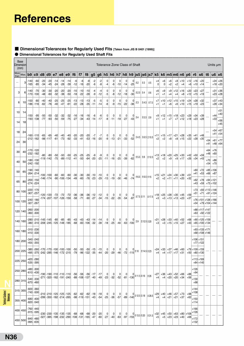
N36
N
Technic
al Guida
nce /
Referen
ces
References
■ Dimensional Tolerances for Regularly Used Fits [Taken from JIS B 0401 (1999)]
● Dimensional Tolerances for Regularly Used Shaft Fits
Base Dimension
(mm)Tolerance Zone Class of Shaft Units μm
More than
Max. b9 c9 d8 d9 e7 e8 e9 f6 f7 f8 g5 g6 h5 h6 h7 h8 h9 js5 js6 js7 k5 k6 m5 m6 n6 p6 r6 s6 t6 u6 x6
Q 3 -140-165
-60-85
-20-34
-20-45
-14-24
-14-28
-14-39
-6-12
-6-16
-8-20
-2-6
-2-8
0-4
0-6
0-10
0-14
0-25 ±2 ±3 ±5
+40
+60
+6+2
+8+2
+10+4
+12+6
+16+10
+20+14 Q
+24+18
+26+20
3 6 -140-170
-70-100
-30-48
-30-60
-20-32
-20-38
-20-50
-10-18
-10-22
-10-28
-4-9
-4-12
0-5
0-8
0-12
0-18
0-30 ±2.5 ±4 ±6
+6+1
+9+1
+9+4
+12+4
+16+8
+20+12
+23+15
+27+19 Q
+31+23
+36+28
6 10 -150-186
-80-116
-40-62
-40-76
-25-40
-25-47
-25-61
-13-22
-13-28
-13-35
-5-11
-5-14
0-6
0-9
0-15
0-22
0-36 ±3 ±4.5 ±7.5
+7+1
+10+1
+12+6
+15+6
+19+10
+24+15
+28+19
+32+23 Q
+37+28
+43+34
10 14-150-193
-95-138
-50-77
-50-93
-32-50
-32-59
-32-75
-16-27
-16-34
-16-43
-6-14
-6-17
0-8
0-11
0-18
0-27
0-43 ±4 ±5.5 ±9
+9+1
+12+1
+15+7
+18+7
+23+12
+29+18
+34+23
+39+28 Q
+44+33
+51+40
14 18 +56+45
18 24-160-212
-110-162
-65-98
-65-117
-40-61
-40-73
-40-92
-20-33
-20-41
-20-53
-7-16
-7-20
0-9
0-13
0-21
0-33
0-52 ±4.5 ±6.5±10.5
+11+2
+15+2
+17+8
+21+8
+28+15
+35+22
+41+28
+48+35
Q +54+41
+67+54
24 30 +54+41
+61+48
+77+64
30 40 -170-232
-120-182 -80
-119-80
-142-50-75
-50-89
-50-112
-25-41
-25-50
-25-64
-9-20
-9-25
0-11
0-16
0-25
0-39
0-62 ±5.5 ±8 ±12.5
+13+2
+18+2
+20+9
+25+9
+33+17
+42+26
+50+34
+59+43
+64+48
+76+60Q
40 50 -180-242
-130-192
+70+54
+86+70
50 65 -190-264
-140-214 -100
-146-100-174
-60-90
-60-106
-60-134
-30-49
-30-60
-30-76
-10-23
-10-29
0-13
0-19
0-30
0-46
0-74 ±6.5 ±9.5±15
+15+2
+21+2
+24+11
+30+11
+39+20
+51+32
+60+41
+72+53
+85+66
+106+87Q
65 80 -200-274
-150-224
+62+43
+78+59
+94+75
+121+102
80 100 -220-307
-170-257 -120
-174-120-207
-72-107
-72-126
-72-159
-36-58
-36-71
-36-90
-12-27
-12-34
0-15
0-22
0-35
0-54
0-87 ±7.5±11 ±17.5
+18+3
+25+3
+28+13
+35+13
+45+23
+59+37
+73+51
+93+71
+113+91
+146+124Q
100 120 -240-327
-180-267
+76+54
+101+79
+126+104
+166+144
120 140 -260-360
-200-300
-145-208
-145-245
-85-125
-85-148
-85-185
-43-68
-43-83
-43-106
-14-32
-14-39
0-18
0-25
0-40
0-63
0-100 ±9 ±12.5±20
+21+3
+28+3
+33+15
+40+15
+52+27
+68+43
+88+63
+117+92
+147+122
Q Q140 160 -280-380
-210-310
+90+65
+125+100
+159+134
160 180 -310-410
-230-330
+93+68
+133+108
+171+146
180 200 -340-455
-240-355
-170-242
-170-285
-100-146
-100-172
-100-215
-50-79
-50-96
-50-122
-15-35
-15-44
0-20
0-29
0-46
0-72
0-115±10 ±14.5±23
+24+4
+33+4
+37+17
+46+17
+60+31
+79+50
+106+77
+151+122
Q Q Q200 225 -380-495
-260-375
+109+80
+159+130
225 250 -420-535
-280-395
+113+84
+169+140
250 280 -480-610
-300-430 -190
-271-190-320
-110-162
-110-191
-110-240
-56-88
-56-108
-56-137
-17-40
-17-49
0-23
0-32
0-52
0-81
0-130±11.5±16 ±26
+27+4
+36+4
+43+20
+52+20
+66+34
+88+56
+126+94Q Q Q Q
280 315 -540-670
-330-460
+130+98
315 355 -600-740
-360-500 -210
-299-210-350
-125-182
-125-214
-125-265
-62-98
-62-119
-62-151
-18-43
-18-54
0-25
0-36
0-57
0-89
0-140±12.5±18 ±28.5
+29+4
+40+4
+46+21
+57+21
+73+37
+98+62
+144+108Q Q Q Q
355 400 -680-820
-400-540
+150+114
400 450 -760-915
-440-595 -230
-327-230-385
-135-198
-135-232
-135-290
-68-108
-68-131
-68-165
-20-47
-20-60
0-27
0-40
0-63
0-97
0-155±13.5±20 ±31.5
+32+5
+45+5
+50+23
+63+23
+80+40
+108+68
+166+126Q Q Q Q
450 500 -840-995
-480-635
+172+132
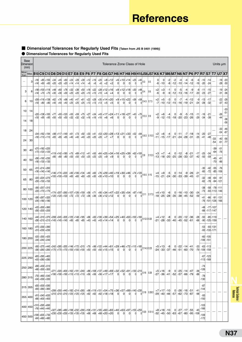
N37
N
Technical Guidance / References
References
■ Dimensional Tolerances for Regularly Used Fits [Taken from JIS B 0401 (1999)]
● Dimensional Tolerances for Regularly Used Fits
Base Dimension
(mm)Tolerance Zone Class of Hole Units μm
More than
Max. B10 C9 C10 D8 D9 D10 E7 E8 E9 F6 F7 F8 G6 G7 H6 H7 H8 H9 H10JS6JS7 K6 K7 M6 M7 N6 N7 P6 P7 R7 S7 T7 U7 X7
Q 3 +180+140
+85+60
+100+60
+34+20
+45+20
+60+20
+24+14
+28+14
+39+14
+12+6
+16+6
+20+6
+8+2
+12+2
+60
+100
+140
+250
+400±3 ±5
0-6
0-10
-2-8
-2-12
-4-10
-4-14
-6-12
-6-16
-10-20
-14-24 Q
-18-28
-20-30
3 6 +188+140
+100+70
+118+70
+48+30
+60+30
+78+30
+32+20
+38+20
+50+20
+18+10
+22+10
+28+10
+12+4
+16+4
+80
+120
+180
+300
+480±4 ±6
+2-6
+3-9
-1-9
0-12
-5-13
-4-16
-9-17
-8-20
-11-23
-15-27 Q
-19-31
-24-36
6 10 +208+150
+116+80
+138+80
+62+40
+76+40
+98+40
+40+25
+47+25
+61+25
+22+13
+28+13
+35+13
+14+5
+20+5
+90
+150
+220
+360
+580±4.5 ±7.5
+2-7
+5-10
-3-12
0-15
-7-16
-4-19
-12-21
-9-24
-13-28
-17-32 Q
-22-37
-28-43
10 14+220+150
+138+95
+165+95
+77+50
+93+50
+120+50
+50+32
+59+32
+75+32
+27+16
+34+16
+43+16
+17+6
+24+6
+110
+180
+270
+430
+700±5.5 ±9
+2-9
+6-12
-4-15
0-18
-9-20
-5-23
-15-26
-11-29
-16-34
-21-39 Q
-26-44
-33-51
14 18 -38-56
18 24+244+160
+162+110
+194+110
+98+65
+117+65
+149+65
+61+40
+73+40
+92+40
+33+20
+41+20
+53+20
+20+7
+28+7
+130
+210
+330
+520
+840±6.5 ±10.5
+2-11
+6-15
-4-17
0-21
-11-24
-7-28
-18-31
-14-35
-20-41
-27-48
Q -33-54
-46-67
24 30 -33-54
-40-61
-56-77
30 40 +270+170
+182+120
+220+120 +119
+80+142
+80+180
+80+75+50
+89+50
+112+50
+41+25
+50+25
+64+25
+25+9
+34+9
+160
+250
+390
+620
+1000±8 ±12.5
+3-13
+7-18
-4-20
0-25
-12-28
-8-33
-21-37
-17-42
-25-50
-34-59
-39-64
-51-76Q
40 50 +280+180
+192+130
+230+130
-45-70
-61-86
50 65 +310+190
+214+140
+260+140 +146
+100+174+100
+220+100
+90+60
+106+60
+134+60
+49+30
+60+30
+76+30
+29+10
+40+10
+190
+300
+460
+740
+1200±9.5 ±15
+4-15
+9-21
-5-24
0-30
-14-33
-9-39
-26-45
-21-51
-30-60
-42-72
-55-85
-76-106Q
65 80 +320+200
+224+150
+270+150
-32-62
-48-78
-64-94
-91-121
80 100 +360+220
+257+170
+310+170 +174
+120+207+120
+260+120
+107+72
+126+72
+159+72
+58+36
+71+36
+90+36
+34+12
+47+12
+220
+350
+540
+870
+1400±11 ±17.5
+4-18
+10-25
-6-28
0-35
-16-38
-10-45
-30-52
-24-59
-38-73
-58-93
-78-113
-111-146Q
100 120 +380+240
+267+180
+320+180
-41-76
-66-101
-91-126
-131-166
120 140 +420+260
+300+200
+360+200
+208+145
+245+145
+305+145
+125+85
+148+85
+185+85
+68+43
+83+43
+106+43
+39+14
+54+14
+250
+400
+630
+1000
+1600±12.5±20
+4-21
+12-28
-8-33
0-40
-20-45
-12-52
-36-61
-28-68
-48-88
-77-117
-107-147
Q Q140 160 +440+280
+310+210
+370+210
-50-90
-85-125
-119-159
160 180 +470+310
+330+230
+390+230
-53-93
-93-133
-131-171
180 200 +525+340
+355+240
+425+240
+242+170
+285+170
+355+170
+146+100
+172+100
+215+100
+79+50
+96+50
+122+50
+44+15
+61+15
+290
+460
+720
+1150
+1850±14.5±23
+5-24
+13-33
-8-37
0-46
-22-51
-14-60
-41-70
-33-79
-60-106
-105-151
Q Q Q200 225 +565+380
+375+260
+445+260
-63-109
-113-159
225 250 +605+420
+395+280
+465+280
-67-113
-123-169
250 280 +690+480
+430+300
+510+300 +271
+190+320+190
+400+190
+162+110
+191+110
+240+110
+88+56
+108+56
+137+56
+49+17
+69+17
+320
+520
+810
+1300
+2100±16 ±26
+5-27
+16-36
-9-41
0-52
-25-57
-14-66
-47-79
-36-88
-74-126Q Q Q Q
280 315 +750+540
+460+330
+540+330
-78-130
315 355 +830+600
+500+360
+590+360 +299
+210+350+210
+440+210
+182+125
+214+125
+265+125
+98+62
+119+62
+151+62
+54+18
+75+18
+360
+570
+890
+1400
+2300±18 ±28.5
+7-29
+17-40
-10-46
0-57
-26-62
-16-73
-51-87
-41-98
-87-144Q Q Q Q
355 400 +910+680
+540+400
+630+400
-93-150
400 450 +1010+760
+595+440
+690+440 +327
+230+385+230
+480+230
+198+135
+232+135
+290+135
+108+68
+131+68
+165+68
+60+20
+83+20
+400
+630
+970
+1550
+2500±20 ±31.5
+8-32
+18-45
-10-50
0-63
-27-67
-17-80
-55-95
-45-108
-103-166Q Q Q Q
450 500 +1090+840
+635+480
+730+480
-109-172

N38
N
Technic
al Guida
nce /
Referen
ces
■ Dimensional Tolerances and Fits [Taken from JIS B 0401 (1999]
● Standard Hole Fit for Regular Use
Standard Hole
Tolerance Zone Class of Shaft
Clearance Fit Transition Fit Interference Fit
H6g5 h5 js5 k5 m5
f6 g6 h6 js6 k6 m6 n6* p6*
H7f6 g6 h6 js6 k6 m6 n6 p6* r6* s6 t6 u6 x6
e7 f7 h7 js7
H8
f7 h7
e8 f8 h8
d9 e9
H9d8 e8 h8
c9 d9 e9 h9
H10 b9 c9 d9
Note: These fittings produce exceptions depending on dimension category.
● Standard Shaft Fit for Regular Use
Standard Shaft
Tolerance Zone Class of Hole
Clearance Fit Transition Fit Interference Fit
h5 H6 JS6 K6 M6 N6* P6
h6F6 G6 H6 JS6 K6 M6 N6 P6*
F7 G7 H7 JS7 K7 M7 N7 P7* R7 S7 T7 U7 X7
h7E7 F7 H7
F8 H8
h8D8 E8 F8 H8
D9 E9 H9
h9
D8 E8 H8
C9 D9 E9 H9
B10 C10 D10
Note: These fittings produce exceptions depending on dimension category.
● Interrelationship of Tolerance Zones for Regularly Used Standard Hole Fits
Note: The above table is for standard dimensions of more than 18 mm and less than or equal to 30 mm.
● Interrelationship of Tolerance Zones for Regularly Used Standard Shaft Fits
Note: The above table is for standard dimensions of more than 18 mm and less than or equal to 30 mm.
Fit
Tolerance Zone Class of Hole
H6 H7 H8 H9 h5 h6 h7 h8 h9H10
50 200
150
100
50
0
0
-50
-100
-150
-200 -50
f6 g5 g6 h5 h6 js5 js6k5 k6 m5 m6 n6 p6 e7 f6 f7 g6 h6 h7 js6 js7 k6 m6n6 p6 r6 s6 t6 u6 x6 d9 e8 e9 f7 f8 h7 h8 c9 d8 d9 g8 e9 h8 h9 b9 c9 d9 M6 JS6 K5 M6 N6 P6 F6 F7 G6 G7 H6 H7 JS6 JS7 K6 K7 M6 M7 N6 N7 P6 P7 R7 S7 T7 U7 X7 E7 F7 F8 H7 H8 D8 D9 E8 E9 F8 H8 H9 B10 C9 C10 D8 D9 D10 E8 E9 H8 H9
H10
H9
H8H7H6
h5h6 h6
h7h8
h9
Dim
ensi
onal
Diff
eren
ce (µ
m)
Dim
ensi
onal
Diff
eren
ce (µ
m)
Standard Hole
Fit
Tolerance Zone Class of Shaft
Cle
aran
ce F
it
Tran
sitio
n Fi
t
Inte
rfere
nce
Fit Clearance Fit Transition Fit Interference Fit
Slidin
g
Driv
ing
Press
Str
on
g P
ress
Shrin
kage
Loose
Lig
ht
Roll
Roll
Cle
aran
ce F
it
Cle
aran
ce F
it
StandardShaft
Inte
rfere
nce
Fit
Tran
sitio
n Fi
t
Cle
ara
nce
Fit
Cle
aran
ce F
it
Tran
sitio
n Fi
t
Inte
rfere
nce
Fit
Cle
aran
ce F
it
Cle
aran
ce F
it
Cle
aran
ce F
itClearance Fit
References

N39
N
Technical Guidance / References
References
■ Finished Surface Roughness● Types and Definitions of Typical Surface Roughness
Types Symbol Method of Determination Descriptive Figure
Max
imum
Hei
ght
*1)
Rz
This is the value expressed in micrometers (μm), obtained by extracting from the roughness curve a segment of the reference length in the direction of the mean line and measuring the distance from the d eepest valley to the highest peak of the extracted segment in the direction of the longitudinal magnification of that roughness curve.Remarks: When obtaining Rz, care must be taken
to extract a segment of the reference length from a portion having no unusually high peaks and deep valleys as they are considered as flaws.
L
Rp
Rz
Rv
m
Rz = Rp + Rv
Cal
cula
ted
Rou
ghne
ss
Ra
This is the value expressed in micrometers (μm), obtained by extracting from the roughness curve a segment of the reference length in the direction of the mean line, plotting a roughness curve of y = f(x) with the X-axis set in the direction and the Y-axis set in the direction of the extracted segment, and using the following formula.
L
Ra
m
L
L
Ra= ʃ10
Ten-
poin
t Mea
n R
ough
ness
*2)
RzJIS
This is the value expressed in micrometers (μm), obtained by extracting from the roughness curve a segment of the reference length in the direction of the mean line, measuring the heights of the highest to 5th highest peaks (Yp) as well as the heights of the deepest to 5th deepest valleys (Yv) in the direction of the longitudinal magnification of that mean line of the that roughness curve, and calculating the sum of the mean of the absolute values of Yp and that of Yv.
L
Yp1
Yp2 Yp3 Yp4
Yp5
Yv1 Yv2 Yv3
Yv4
Yv5
m
(Yp1+Yp2+Yp3+Yp4+Yp5)+(Yv1+Yv2+Yv3+Yv4+Yv5)5
RzJIS=
Designated values of the above types of surface roughness, standard reference length values and the triangular symbol classifications are shown on the table on the right.
● Relationship with Triangular Symbols
DesignatedValues for
*1)Rz
Designated Values for
Ra
DesignatedValues for
*2)RzJIS
StandardReference
Length Values, (mm)
*Triangular Symbols
(0.05)0.10.20.4
(0.012)0.0250.050.10
(0.05)0.10.20.4
0.25
0.8 0.20 0.8
1.63.26.3
0.400.801.6
1.63.26.3
0.8
12.5(18)25
3.26.3
12.5(18)25
2.5
(35)50
(70)100
12.525
(35)50
(70)100
8
(140)200
(280)400
(560)
(50)(100)
(140)200
(280)400
(560)
— —
Remarks: The designated values in the brackets do not apply unless otherwise stated.
* Due to the revision of JIS in 1994, the finishing symbols, triangular (
J
) and wavy (~) symbols, were abolished.
JJJJ
JJJ
JJ
J