Technical Explanation for Wiring SystemsTechnical Explanation for Wiring Systems Introduction What...
12
Sensors Switches Safety Components Relays Control Components Automation Systems Motion / Drives Energy Conservation Support / Environment Measure Equipment Power Supplies / In Addition Others Common 1 CSM_Connector_TG_E_1_1 Technical Explanation for Wiring Systems Introduction What Is a Wiring System? A Wiring System is a device that is used to convert a connection to a connector to connect (wire) a device or circuit. Converting connections to connectors makes it possible to connect and disconnect devices with just your hands or simple tools. This document classifies Wiring Systems as follows. Connector-Terminal Block Conversion Unites A Connector-Terminal Block Conversion Unit is a terminal block conversion unit with a prewired connector that can be used to wire all the I/O for a programmable controller with a single cable. Industrial Ethernet Connectors Industrial Ethernet Connectors support industrial networks based on Ethernet, such as EtherCAT ® . Sensor I/O Connectors Sensor I/O Connectors are used to convert the wiring for a sensor into a connector. PCB Connectors PCB Connectors are specialized connectors that are used to connect PCBs to other PCBs or to cables of electronic devices and to connect mounted electronic parts. Classifications Connector-Terminal Block Conversion Unites Name Main application locations Main types Industrial connectors Units for PLCs Units for General-purpose Devices Industrial Ethernet Connectors Name Main application locations Main types Industrial connectors Cables with Standard RJ45 Connectors Cables with Rugged RJ45 Connectors Cables with Waterproof M12 Connectors Units for PLCs: Ideal for connecting to PLCs from various companies. Units for General-purpose Devices: Support a variety of applications with high versatility. Cable with Standard RJ45 Connectors: Ideal for in-cabinet Cables with Rugged or Waterproof Connectors: Ideal for out-of-cabinet
Transcript of Technical Explanation for Wiring SystemsTechnical Explanation for Wiring Systems Introduction What...
SensorsSwitches
Safety Components
RelaysControl Com
ponentsAutom
ation Systems
Motion / Drives
Energy Conservation Support / Environment Measure Equipment
Power Supplies /In Addition
OthersCom
mon
1
CSM_Connector_TG_E_1_1
Technical Explanation for Wiring Systems
IntroductionWhat Is a Wiring System?A Wiring System is a device that is used to convert a connection to a connector to connect (wire) a device or circuit.Converting connections to connectors makes it possible to connect and disconnect devices with just your hands or simple tools.This document classifies Wiring Systems as follows.
Connector-Terminal Block Conversion UnitesA Connector-Terminal Block Conversion Unit is a terminal block conversion unit with a prewired connector that can be used to wire all the I/O for a programmable controller with a single cable.
Industrial Ethernet ConnectorsIndustrial Ethernet Connectors support industrial networks based on Ethernet, such as EtherCAT®.
Sensor I/O ConnectorsSensor I/O Connectors are used to convert the wiring for a sensor into a connector.
PCB ConnectorsPCB Connectors are specialized connectors that are used to connect PCBs to other PCBs or to cables of electronic devices and to connect mounted electronic parts.
Classifications
Connector-Terminal Block Conversion Unites
Name Main application locations Main types
Industrial connectors
Units for PLCs
Units for General-purpose Devices
Industrial Ethernet Connectors
Name Main application locations Main types
Industrial connectors
Cables with Standard RJ45 Connectors
Cables with Rugged RJ45 Connectors
Cables with Waterproof M12 Connectors
Units for PLCs: Ideal for connecting to PLCs from various companies.
Units for General-purpose Devices: Support a variety of applications with high versatility.
Cable with Standard RJ45 Connectors: Ideal for in-cabinet
Cables with Rugged or Waterproof Connectors: Ideal for out-of-cabinet

Technical Explanation for Wiring Systems
2
SensorsSwitches
Safety Components
RelaysControl Com
ponentsAutom
ation Systems
Motion / Drives
Energy Conservation Support / Environment Measure Equipment
Power Supplies /In Addition
OthersCom
mon
Sensor I/O Connectors
Name Main application locations Main types
Industrial connectors
Waterproof Round Connectors
Connector Terminal Boxes
e-CON Connectors
PCB Connectors
Name Main application locations Main types
FPC connectors FPC/FFC Connectors
Consumer and commercial connectors
MIL Connectors
PCB Terminal Blocks
HM/ZD Connectors
Half-pitch Connectors
DIN Connectors
I/O Connectors
Jumper Plugs
IC Sockets
Electroformed partsBattery Connectors
Probe Pin
Refer to the OMRON Electronic Components Web (www.omron.com/ecb/) for details on Connectors for PCBs.
SensorsConnectors
Connector Terminal Boxes: For multiple sensors
Waterproof Round Connectors: Connecting outside control panelse-CON Connectors: Connecting to a connector with e-CON specifications
PCB Connectors: Mounted on internal circuits for a variety of devices, from industrial devices to consumer and commercial devices

Technical Explanation for Wiring Systems
3
SensorsSwitches
Safety Components
RelaysControl Com
ponentsAutom
ation Systems
Motion / Drives
Energy Conservation Support / Environment Measure Equipment
Power Supplies /In Addition
OthersCom
mon
Product Lineup and FeaturesConnector-Terminal Block Conversion UnitesA Connector-Terminal Block Conversion Unit is a terminal block conversion unit with a prewired connector that can be used to wire all the I/O for a programmable controller (PLC) with a single cable.OMRON provides Units for PLCs, which have wiring patterns specialized for PLC connections, and Units for general-purpose devices.Recently, the use of devices with push-in terminal blocks has been increasing in order to improve work efficiency. In particular, push-in terminal blocks on Connector-Terminal Block Conversion Units that are used to connect to PLCs with their many signals make it possible to reduce space requirements and reduce wiring work.OMRON’s lineup also includes conventional Units with phillips screws or slotted screws, Units with e-CON specification, and more.
Features of Units with Push-in Terminal BlocksStructure
With a push-in terminal block, a wire is inserted and the clamp spring presses against the wire to lock it into place.Three types of wire can be used: 1) wires with ferrules, 2) solid wires, and 3) stranded wires.
Connecting a WireIf you use a wire with a ferrule, you can wire by inserting the ferrule into the push-in terminal block. Also, there is no need for retightening screws after shipping, so installation can be performed immediately.
Pullout StrengthThe pullout strengths of push-in terminal blocks are specified in the JIS C 8201-7-1 or IEC 60947-7-1 standard.
Example: Pullout Strengths for Wires with Ferrules
Refer to your OMRON website for details.
Wiring method
Connector-Terminal Block Conversion Unites
Units for General-purpose Devices
Units for General-purpose Devices
Common Terminal Blocks
Units for PLCsUnits for PLCs with Power Supply Terminals
Units for PLCs without Power Supply Terminals
e-CON
Pu
sh
-in
sp
rin
g
Ph
illi
ps
sc
rew
Slo
tte
ds
cre
w
(ris
e u
p)
1 )
2)
3)
Clamp spring The clamp springpresses the wire tolock it into place.
Conductivemetal fitting
Wire thickness (cross-sectional area) Value in JIS standard
AWG20 (0.52 mm2) 20 N
AWG22 (0.33 mm2) 15 N
The clamp spring securelylocks the wire.

Technical Explanation for Wiring Systems
4
SensorsSwitches
Safety Components
RelaysControl Com
ponentsAutom
ation Systems
Motion / Drives
Energy Conservation Support / Environment Measure Equipment
Power Supplies /In Addition
OthersCom
mon
Industrial Ethernet ConnectorsIndustrial Ethernet Connectors support industrial networks based on EtherCAT® and other protocols.OMRON provides Cables with Standard Connectors, which reduce cable routing space, Cables with Rugged Connectors, which are suitable for wiring outside control panels, and Cables with Waterproof Connectors.
Features of Cables with Standard RJ45 ConnectorsShape of RJ45 Connector
RJ45 Connectors are one form of connector that is used to connect communications cables such as LAN cables.
Minimum Cable Bending Radius: 25 mm
The small cable bending radius makes it possible to reduce cable routing space.
LSZH Cable with Double Shield
Double-shield cables with overall braiding and individual foil shield on each wire pair to reduce EMC interference in industrial environments.
Features of Cables with Rugged RJ45 ConnectorsShape of RJ45 Connector
Tough Latch RJ45 Connectors are suitable for connections outside of the control panels.
PVC Cable with Double Shield
Double-shield cables with overall braiding and individual foil shield on each wire pair to reduce EMC interference in industrial environments
Assembly Connectors
OMRON’s lineup also includes Assembly Connectors that enable you to easily assemble Ethernet cables onsite without crimping tools or other special tools.For details, refer to the Industrial Connector Catalog (Cat. No. X082).
Minimum cable bending radius: 25 mm
58 mm
Overall braiding and individual foil shield on each wire pair
Tough latch
Overall braiding and individual foil shield on each wire pair

Technical Explanation for Wiring Systems
5
SensorsSwitches
Safety Components
RelaysControl Com
ponentsAutom
ation Systems
Motion / Drives
Energy Conservation Support / Environment Measure Equipment
Power Supplies /In Addition
OthersCom
mon
Features of Cables with Waterproof Connectors (Round, M12)Resistance to Environments
These connectors are environment resistant (waterproof) and achieve IP67 (IEC standard) compliance with their shield structure.For information on IP67 (IEC standard), refer to the Degree of Protection.
Smartclick Connectors
With a Smartclick Connector, connection is completed by turning the connector approximately 1/8th of a turn.
Shield structure
Connection is completed with a rotation of approximately 1/8. Confirm
connection with visual marks.
Insert all theway in. 1/8th of a turn
Click!
Connectors(1) Reduced Wiring Work and No Torque Management
Because connection is completed with approximately 1/8th of a turn, installation time is reduced. Also, you can confirm the completion of connection with the visible marks.
(2) No Periodic RetighteningThanks to the bayonet lock structure, machine vibration does not loosen the connector, eliminating the need for periodic retightening.
(3) Work Procedure StandardizationThe distinct clicking sensation when the connector locks prevents insufficient tightening.
(4) Compatible with M12 Screw Connectors
Even with existing equipment that uses M12 screw connectors, you can connect any combination of connectors.* When a Smartclick Connector is connected to a screw connector, the
connector is screwed on to make the connection.
Reduced to approx. 1/3*
Screw connections
Smartclick
Installation Time
* Based on actual values measured by OMRON.
* Enlargement of Bayonet Lock Mechanism
Click!
XS5 Smartclick Plug Connector M12 plug connector
XS5 Smartclick Socket Connector
Twist-and-click connection Screw connection
M12 socket connector Screw connection Screw connection
Technical Explanation for Wiring Systems
6
SensorsSwitches
Safety Components
RelaysControl Com
ponentsAutom
ation Systems
Motion / Drives
Energy Conservation Support / Environment Measure Equipment
Power Supplies /In Addition
OthersCom
mon
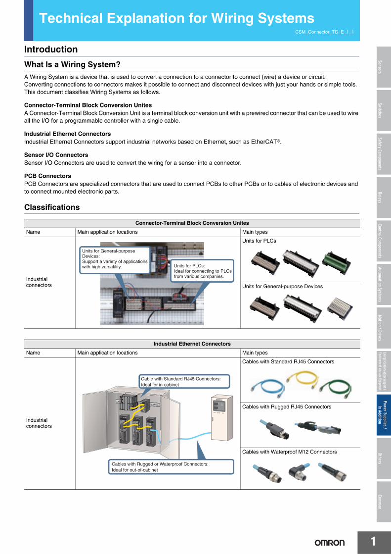
Sensor I/O ConnectorsSensor I/O Connectors are used to convert the wiring for a sensor into a connector.We offer various models to suit different uses.
Features of Pressure-welded Assembly ConnectorsClarifies Assembly Completion PositionAssembly is completed with any type of cable simply by pressing the cable all the way in. The tightened position is clear, so you can visually confirm assembly completion.
Wide Range of CablesTwo sizes of bushings (one for large-diameter cables and one for small-diameter cables) are provided to support cable diameters from 3 mm to 8 mm.
In addition to these models, you can select from Connectors with IP67 protection, Smartclick Connectors, and other connectors suited to a variety of applications and environments.For details, refer to the Industrial Connectors Catalog (Cat. No. X082).
PCB ConnectorsPCB Connectors are specialized connectors that are used to connect PCBs to other PCBs or to cables of electronic devices and to connect mounted electronic parts.
Type Main use Appearance (typical example)
Connectors attached to Cable Used for sensor and actuator wiring to relay sensor signals or the like.
Connector Assemblies Used to enable using connectors for sensor cables and relay cables.
Sensor Connector Assemblies Used to enable connectors to be integrated with the Sensor body.
Panel-mounting Connectors Used to enable using I/O box connectors mounted to panels.
Y-Joint Connectors Used to wire two sensors to a single cable.
T-Joint Connectors
Aggregate model: Used to wire two sensors to a single cable.Bifurcated model: Used when branching one sensor signal to two cables.Daisy-chain model: Two-wire sensors with contact output can be connected through a daisy chain to obtain AND output.
Connector Terminal Boxes Used to wire multiple sensors to a single cable.
e-CON Connectors Used when the connected device uses e-CON specifications.
A B
C
The tightened position is clear.ned position is clear.
Visual confirmation is possible.
Bushing for small-diameter cable
Refer to the OMRON Electronic Components Web (www.omron.com/ecb/) for details on Connectors for PCBs.

Technical Explanation for Wiring Systems
7
SensorsSwitches
Safety Components
RelaysControl Com
ponentsAutom
ation Systems
Motion / Drives
Energy Conservation Support / Environment Measure Equipment
Power Supplies /In Addition
OthersCom
mon
Explanation of TermsNamesPCB Mounting DimensionsBottom View: View of PCB from solder mounting surface.Top View: View of PCB from part mounting surface.In the datasheets, the bottom view is given for products with DIP terminals and the top view for products with surface mounting terminals.
Triangle MarkThe position of the first terminal on the connector. (Some products have no triangle mark.)
Part Names (HSG, CNT, and Pin Clamp)CNT (contact): Contacts for making electrical connections
designed for use in multi-pole connectors.HSG (housing): A synonym for a molded insulator that, for a
connector with no shell, has the functions of holding the contacts in the correct alignment and insulating the contacts from each other and from any other conductors.
Pin Clamp: Same function as kink treatment. The objective is to increase the strength after mounting.
Twin ContactsA method in which contact is made at two points.
Separated ContactA contact that can be attached to or removed from the housing.
Dummy BoardA board inserted instead of the single-row contacts when they are left empty.
Insulation BarrelThe part of a contact that crimps the insulating sheath of a wire.
LanceThe lance-like projections arranged on a contact to secure it in the housing. A synonym for locking tab.
Plugs and SocketsConnectors are classified as plugs or sockets according to the shape of the contact section or according to the connector that has the contacts.Plug: Same as male connector, pin header, or post.
A connector with fixed contacts.Mates with the socket contacts to make electrical connections.
Socket: Same as female connector or receptacle.A connector with moving contacts.Mates with the plug contacts to make electrical connections.
HarnessA part with wires attached to connectors.
Connector Mounting TabA part on both ends of the connector’s housing mating section.Used as a space for installing a screw, pin clamp, or other fixture.
Minimum Packing UnitThe minimum number packed for shipment from the factory.
Number of PinsThe number of contacts.A synonym for pin count.
Pitch (Between Rows)The interval between terminals in the long direction (distance between the terminal centers).There is also a pitch between rows, which indicates the interval (distance between terminal centers) between rows of terminals in the long direction.
Through HolesHoles into which terminals are inserted in order to connect connector terminals to the PCB wiring pattern.Connector terminals are inserted into these holes and soldered to make the electrical connections.A through hole sometimes indicates a hole used to connect the front and rear side wiring patterns of a PCB.
AWGAWG is an abbreviation for American Wire Gauge. It is a conductor standard that indicates the core cross-sectional area for wires generally used in the United States.
PlatingSurface treatment that covers the surface of a metal or other material with a thin metal film (examples: gold plating or tin plating).
CodingProcessing performed on the housing in order to prevent incorrect insertion during connector mating.
Socket contactPlug contact
Insulation barrel
Two-slot IDC pressing
Lance
Technical Explanation for Wiring Systems
8
SensorsSwitches
Safety Components
RelaysControl Com
ponentsAutom
ation Systems
Motion / Drives
Energy Conservation Support / Environment Measure Equipment
Power Supplies /In Addition
OthersCom
mon
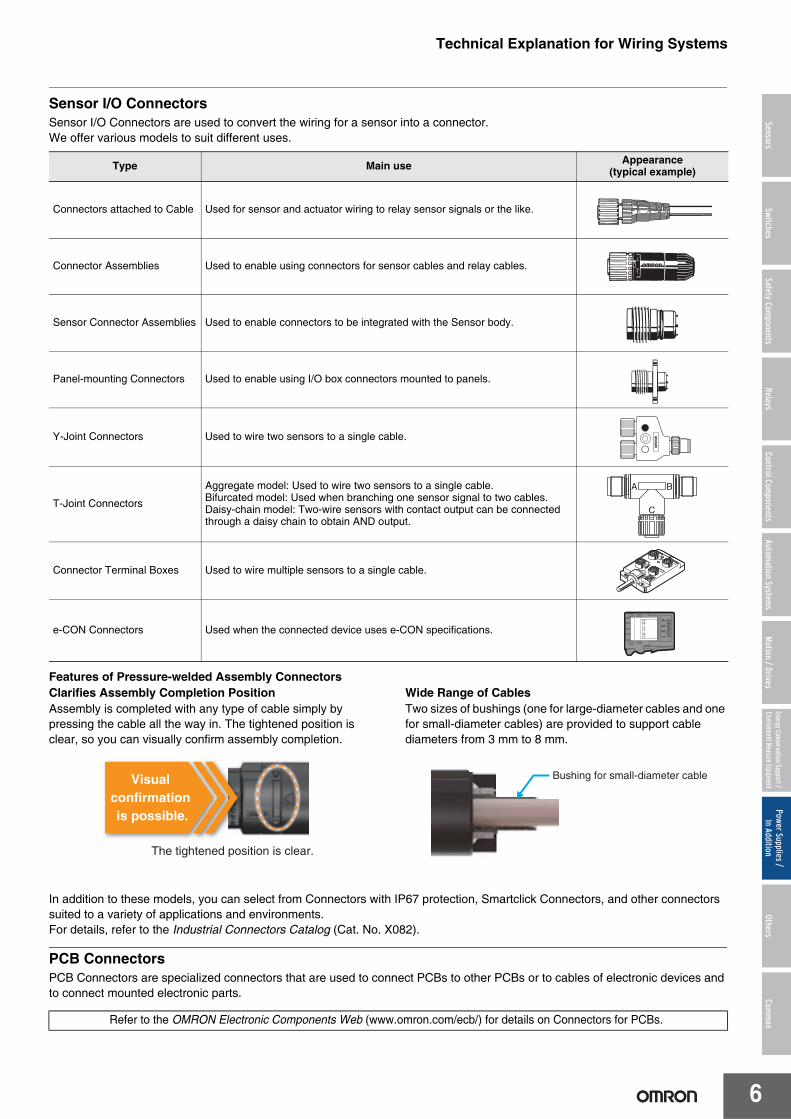
Configurations and StructuresStandard (Perpendicular)When perpendicular printed-wiring boards are connected, a socket straight terminal connector is connected to the motherboard (main board) and a plug right-angle terminal connector is connected to the daughterboard (sub-board).
Reverse (Perpendicular)When perpendicular printed-wiring boards are connected, a plug straight terminal connector is connected to the motherboard (main board) and a socket right-angle terminal connector is connected to the daughterboard (sub-board).
StackingPlacing printed-wiring boards on top of each other and connecting them parallel to each other.The distance between the stacked circuit boards is called the stacking height.
HorizontalConnecting two printed-wiring boards so that they are horizontal to each other.
One-piece ConnectorA connector that connects directly.This term indicates a female connector that directly connects to a contact pattern on a printed-wiring board.A card edge connector is a type of one-piece connector.
Two-piece ConnectorA connector that connects indirectly.This term indicates a type of connectors, male and female connectors, which are mounted on respective printed-wiring boards and are mated to each other to connect the PCBs.
Low ProfileA term that described a device with a low height.Low-profile connectors are used in the following cases:• When the vertical distance between PCBs is small when the
connectors are mated.• When the heights of the parts mounted on a PCB are low.
Wiping EffectFor a connector, this means that during mating, the socket contacts wipe any foreign matter off the contact surfaces of the plug contacts so that contact is made between clean surfaces.
Fine FittingConnecting with press fitting using OMRON’s unique terminal shape.
Solder-free Connection Section (Fine-Fit Section) Structural Diagram
Backplane (Rack) SystemA configuration in which multiple PCBs are placed in parallel with a direction intersecting the motherboard and joined by means of connectors.
Low Insertion Force DesignA plug tip shape like that in the figure on the right is used to reduce the insertion force. The plug tip shape is regulated by the DIN standards, but the insertion force can be reduced by slightly rounding between the straight section of the plug and the tip section as in the figure on the right.
Bus Line ConnectionA form of connection in which multiple devices are connected one at a time to a single main line.
Daisy ChainA technique for connecting peripherals or other devices with cables in which the devices are connected in series.
Daughterboard (sub-board)
Motherboard (main board)
Plug right-angle terminal connector
Socket straight terminal connector
Daughterboard (sub-board)
Motherboard (main board)
Socket right-angle terminal connector
Plug straight terminal connector
Socket straight terminal connector
Plug straight terminal connector
Socket right-angle terminal connector
Plug right-angle terminal connector
Cross-sectionalDiagram
• The cross section has a W shape.
• The two points at the bottom serve as guide rails to minimize torsion.
• The two pairs of fins at the top deform to fit in the PCB through hole.
(DIN standard)
(DIN standard)
Without R
Inse
rtio
nR
emov
al
With R

Technical Explanation for Wiring Systems
9
SensorsSwitches
Safety Components
RelaysControl Com
ponentsAutom
ation Systems
Motion / Drives
Energy Conservation Support / Environment Measure Equipment
Power Supplies /In Addition
OthersCom
mon
SequenceA connection structure in which live wires can be connected and disconnected because the pins are given different lengths so that when connectors are mated, the power terminals connect first and the signal terminals are connected with power already being supplied and when connectors are disconnected, the power terminals are disconnected with the signal terminals already disconnected.Terminals that have different terminal lengths to achieve this are called sequential terminals.
Three-step SequenceA structure that combines normal terminals and sequential terminals to give a time difference to three-step contact system.
Electrical PerformanceRated CurrentA current that serves as a reference for connector use.The rated current is normally specified according to the temperature rise limit of the connector contact section, connection section, etc.
Rated VoltageA voltage that serves as a reference for connector use
Contact ResistanceThe electrical resistance between contacts when the connectors are mated in the normal usage state.This electrical resistance is found by supplying the specified test current and measuring the voltage at the specified contact location. Therefore, this always includes the resistance of the contact conductors. Normally, a low-level contact resistance (measurement current: 100 mA max., open voltage: 20 mV max.) is given.
Insulation ResistanceThe value of the resistance to the leakage current that flows through the insulator when the specified voltage is applied between adjacent contacts on the connector or between a contact and other adjacent metal.
Dielectric StrengthThe limit to the voltage between adjacent contacts on the connector or between a contact and other adjacent metal for which no insulation breakdown, flashover, or other abnormality occurs within a certain time (normally, 1 minute).
3rd contact
Normal
Sequence
Sequence
2nd contact1st contactNormal
Normal
Sequence
Technical Explanation for Wiring Systems
10
SensorsSwitches
Safety Components
RelaysControl Com
ponentsAutom
ation Systems
Motion / Drives
Energy Conservation Support / Environment Measure Equipment
Power Supplies /In Addition
OthersCom
mon
Mechanical PerformanceInsertion ToleranceThe minimum number of repeated connection (insertion) and disconnection (removal) operations that a connector can withstand.The number of operations for which the base metal is first exposed is used as a guideline.Note: This is not the number of operations that indicates the contact
resistance rise limit.
Ambient Operating Temperature RangeThe ambient temperature range around the connector in which it can be used in normal condition.(There must be no condensation at low temperatures.)
Contact Insertion Force and Contact Removal ForceThe force required to connect or disconnect the plug contacts and socket contacts.Normally, a gauge specified for the specific connector is used instead of the plug contact. For the contact insertion force, the maximum value is specified and for the contact removal force, the minimum value is specified.
Total Insertion Force and Total Removal ForceThe force required to connect or disconnect the entire plug and socket. Normally, for the total insertion force, the maximum value is specified and for the total removal force, the minimum value is specified.
VibrationThe range of mechanical vibration in which the connector satisfies its performance and characteristics requirements.
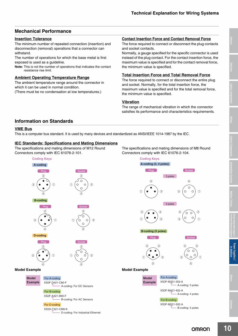
Information on StandardsVME BusThis is a computer bus standard. It is used by many devices and standardized as ANSI/IEEE 1014-1987 by the IEC.
IEC Standards: Specifications and Mating DimensionsThe specifications and mating dimensions of M12 Round Connectors comply with IEC 61076-2-101.
Model Example
The specifications and mating dimensions of M8 Round Connectors comply with IEC 61076-2-104.
Model Example
SocketPlug
SocketPlug
SocketPlug
Coding Keys
A-coding
D-coding
B-coding
For A-coding
XS5F-D421-C80-F
For B-coding
A-coding: For DC Sensors
XS2F-A421-B90-FB-coding: For AC Sensors
XS5H-T421-CM0-KD-coding: For Industrial Ethernet
For D-coding
Model Example
SocketPlug
SocketPlug
Coding Keys
A-coding (3, 4 poles)
B-coding (5 poles)
3 poles
4 poles
XS3F-M321-302-A
For A-coding
A-coding: 3 poles
XS3F-M421-402-AA-coding: 4 poles
XS3F-M521-502-AB-coding: 5 poles
For B-coding
Model Example

Technical Explanation for Wiring Systems
11
SensorsSwitches
Safety Components
RelaysControl Com
ponentsAutom
ation Systems
Motion / Drives
Energy Conservation Support / Environment Measure Equipment
Power Supplies /In Addition
OthersCom
mon
Further InformationConnector Section StructuresConnectors have a plug (male) side and a socket (female) side. Their structures are shown below.
Example: D-Sub ConnectorsConnector Image Diagram (Plug Side) Connector Image Diagram (Socket Side)
The connector contacts include the plug contacts on the plug side and the socket contacts on the socket side.
Connector Connection MethodsConnectors are divided into various types according to their applications and application locations.
Parts connected with connectors include wires and PCBs as described on the left. Typical connection methods for each are described below.
Wire Connection Methods (Typical Examples)Crimping:
A wire connection technique in which metals are compressed to form a metal structure. The connection is made by applying high pressure to the wire from which the covering has been stripped and to the connector terminal.
IDC pressing: A wire connection technique in which metal is compressed to form a metal structure. By pressing the wire with the covering intact against the contact section with high pressure, the wire covering is pierced through and an electrical connection is made.
Board Connection Methods (Typical Examples)Soldering:
This method makes the connection by melting solder (a mixture of tin, lead, silver, flux, etc.) at high temperature and allowing it to flow into the connection. Industrial methods for automatic soldering include flow soldering and reflow soldering. When complying with an RoHS directive, it is necessary to use lead-free solder.
Press-fitting:This method is used to make connections with an interference fit between the PCB terminals of connectors and the through holes in a PCB.* A through hole is a hole for inserting a terminal into a PCB.
Plug Contacts (Short)
Plug Contacts (Long)Plug Housing
Plug Shell
Finished Appearance Exploded View
Eyelets
Socket ContactsSocket Housing
Eyelets
Socket Shell
Finished Appearance Exploded View
Plug Contact
Socket Contact
Board to Board Connections with Electrical Wires (Board to Wire Connections)
Direct Board to Board Connections (Board to Board Connections)
Device to Device Connections (I/O)
Other (Short Connectors, IC Sockets)
Connectors
PCBs
Device Device
Short Connector IC Socket
IC
Technical Explanation for Wiring Systems
12
SensorsSwitches
Safety Components
RelaysControl Com
ponentsAutom
ation Systems
Motion / Drives
Energy Conservation Support / Environment Measure Equipment
Power Supplies /In Addition
OthersCom
mon
Cable SpecificationsThe cables used for connectors are mainly standard cables (F cables) or oil-resistant cables (P cables).
Standard Cables (F Cables)UL AWM2464, 6-mm dia., 4 cores × AWG20 (0.08/110)• Robot• Fire-retardant• CL3 certified
NFPA (National Fire Protection Association) wire standard for industrial machinery for North America
• PVC (polyvinyl chloride) is used.In 2011, A cables (standard), R cables (robot), F cables (fire-retardant), and CL3 (CL3 certified cables) were all consolidated as F cables.
Oil-resistant Cables (P Cables)6-mm dia., 4 cores × AWG20 (0.12/45)• PUR (polyurethane) is used.
Cable specifications generally specify the following.
Example: Interpreting “UL AWM2464, 6-mm dia., 4 cores × AWG20 (0.08/110)” Standard Cable● UL ...................Indicates a UL-certified part.● AWM2464 .......Specifies the rating, wire part name, and application.● 6-mm dia. ........Specifies the cable outer diameter.● 4×AWG20 .......Specifies that there are four core wires with a gauge of AWG 20.
(0.08/110) ........Specifies that there are 110 wires with a diameter of 0.08 mm in the conductor section. (The smaller the wire diameter and the more wires there are, the higher the bending resistance.)
SmartClick is registered trademark of OMRON Corporation.EtherCAT is a registered trademark and patented technology, licensed by Beckhoff Automation GmbH, Germany.

![6. Wiring Diagram - weidefamily.net coil Transmission control module ... WIRING DIAGRAM 6. Wiring Diagram. MEMO: 21 WIRING DIAGRAM ... 76 6-3 [D6R2] WIRING DIAGRAM 6.](https://static.fdocuments.us/doc/165x107/5aa0cc3b7f8b9a62178ea5e7/6-wiring-diagram-coil-transmission-control-module-wiring-diagram-6-wiring.jpg)