Technical, Environmental and Operational Review Mangrove ...
68
Technical, Environmental and Operational Review Mangrove Mountain Landfill Wisemans Ferry Road, Mangrove Mountain NSW Report Number 610.16783-R01 05 May 2017 NSW EPA 59-61 Goulburn Street Sydney NSW 2000 Version: v0.5 FINAL
Transcript of Technical, Environmental and Operational Review Mangrove ...

Technical, Environmental and Operational Review
Mangrove Mountain Landfill
Wisemans Ferry Road, Mangrove Mountain NSW
Report Number 610.16783-R01
05 May 2017
NSW EPA
59-61 Goulburn Street
Sydney
NSW 2000
Version: v0.5 FINAL

NSW EPA Technical, Environmental and Operational Review Mangrove Mountain Landfill Wisemans Ferry Road, Mangrove Mountain NSW
Report Number 610.16783-R01 05 May 2017
Version v0.5 Final Page ii
SLR Consulting Australia Pty Ltd
Technical, Environmental and Operational Review
Mangrove Mountain Landfill
Wisemans Ferry Road, Mangrove Mountain NSW
PREPARED BY:
SLR Consulting Australia Pty Ltd ABN 29 001 584 612 2 Lincoln Street Lane Cove NSW 2066 Australia (PO Box 176 Lane Cove NSW 1595 Australia) T: +61 2 9427 8100 F: +61 2 9427 8200
[email protected] www.slrconsulting.com
This report has been prepared by SLR Consulting Australia Pty Ltd with all reasonable skill, care and diligence, and taking account of the timescale and resources allocated to it by agreement with the Client.
Information reported herein is based on the interpretation of data collected, which has been accepted in good faith as being accurate and valid.
This report is for the exclusive use of NSW EPA and MDA. No warranties or guarantees are expressed or should be inferred by any third parties. This report may not be relied upon by other parties without written consent from SLR.
No copying, reproduction or publishing of this document in whole or part may be undertaken unless with the written permission of the NSW EPA and SLR Consulting Australia Pty Ltd.
SLR disclaims any responsibility to the Client and others in respect of any matters outside the agreed scope of the work.
DOCUMENT CONTROL
Reference Date Prepared Checked Authorised
610.16783-R01-v0.5 5 May 2017 Alan Dyer J Postlethwaite J Postlethwaite

NSW EPA Technical, Environmental and Operational Review Mangrove Mountain Landfill Wisemans Ferry Road, Mangrove Mountain NSW
Report Number 610.16783-R01 05 May 2017
Version v0.5 Final Page iii
Table of Contents
SLR Consulting Australia Pty Ltd
1 INTRODUCTION 1
1.1 Outline and Scope 1
1.2 Key Objectives 3
1.3 Site Location 5
1.4 Background 5
2 LANDFILL DESIGN REVIEW 8
2.1 Landfill Design Overview 8
2.2 Unlined Cell 1A within the Existing Fill Mound 9
2.2.1 Permeability of the Underlying Hawkesbury Sandstone 10
2.2.2 Geometry of the Underlying Landfill Basal Surface 10
2.2.3 Leachate Head Within the Waste Mass 10
2.2.4 Remaining Considerations 11
2.3 Lined Landfill within the Existing Fill Mound - Cell 1B 11
2.4 Proposed Cells W, X, Y and Z 15
2.4.1 Subgrade Surface 16
2.4.2 Groundwater Under-Cell Drainage 17
2.4.3 Groundwater Side Wall Under-Cell Drainage 19
2.4.4 Lower Protective Geotextile Layer 19
2.4.5 Geosynthetic Clay Liner 19
2.4.6 HDPE Geomembrane 22
2.4.7 Upper Protection Geotextile Layer 23
2.4.8 Leachate Drainage Layer 23
2.4.9 Pipework 25
2.4.10 Protection Padding Sand Layer 26
2.5 Construction Quality Assurance 27
2.5.1 Overview 27
2.5.2 Electrical Leak Detection Survey 27
2.6 Side Liner Geotechnical and Settlement Issues 27
2.7 Connection between Proposed Cells W, X, Y & Z and ‘Existing Fill Mound’ 27
2.8 Construction of a Leachate Collection Gutter 28
2.9 Placement of Future Waste over Historical Landfills 29
2.9.1 Waste Mass Stability 30
2.10 Secondary Environment Protection Measure – Cut-off Trench 31
2.11 Leachate Management 31
2.11.1 Leachate Monitoring 31
2.11.2 Leachate Disposal 31
2.11.3 Leachate Dam Design 32
2.12 Landfill Capping 33

NSW EPA Technical, Environmental and Operational Review Mangrove Mountain Landfill Wisemans Ferry Road, Mangrove Mountain NSW
Report Number 610.16783-R01 05 May 2017
Version v0.5 Final Page iv
Table of Contents
SLR Consulting Australia Pty Ltd
3 STORMWATER ASSESSMENT 35
3.1 Background 35
3.2 Review Considerations 35
3.3 Stormwater Monitoring Program 36
4 GROUNDWATER REVIEW 37
4.1 Background 37
4.2 Overview 37
4.3 Proposed Groundwater Monitoring Bores 39
4.4 Groundwater Monitoring Plans 39
4.4.1 Groundwater Bores 39
4.4.2 Cut Off Trench Riser Monitoring 40
5 SITING CONSIDERATIONS 40
5.1 Background 40
5.2 Review of Guidelines and Regulations 40
6 REVIEW OF HISTORICAL GROUND AND SURFACE WATER MONITORING RESULTS 42
6.1 Background 42
6.2 Review of CES Soil and Water Management Plan 42
6.3 Review of Quarterly Groundwater Monitoring Data 43
6.4 Conclusion 44
7 OPERATIONAL REVIEW 44
7.1 Historic Operational Procedures 44
7.2 Proposed Operational Procedures 44
7.2.1 Cell W Filling Plan 44
7.2.2 Maintenance of Leachate Holding Pond Capacity 45
7.2.3 Cell W Dewatering 46
7.2.4 Reprofiling of the Existing Fill Mound 46
7.2.5 Temporary Storage, Placement and Stockpiling of VENM 47
8 ASSESSMENT OF THE PROPOSAL AND HISTORICAL LANDFILL AGAINST THE REQUIREMENTS OF THE POEO ACT 48
8.1 Overview 48
8.2 POEO Section 45 Clause b 49
8.2.1 Overview of Section 6 49
8.3 POEO Section 45 Clause c 50
8.3.1 POEO Section 45 Clause c in Respect to Mangrove Mountain 50
8.4 POEO Section 45 Clause d 50
8.4.1 POEO Section 45 Clause d in Respect to Mangrove Mountain 50

NSW EPA Technical, Environmental and Operational Review Mangrove Mountain Landfill Wisemans Ferry Road, Mangrove Mountain NSW
Report Number 610.16783-R01 05 May 2017
Version v0.5 Final Page v
Table of Contents
SLR Consulting Australia Pty Ltd
8.5 POEO Section 45 Clause f1 51
8.5.1 POEO Section 45 Clause f1 in Respect to Mangrove Mountain 51
8.6 POEO Section 45 Clause i 51
8.6.1 POEO Section 45 Clause i in Respect to Mangrove Mountain 51
9 RECOMMENDATIONS 52
10 CONCLUSIONS 60
TABLES
Table 1 Scope Requirement Reference Summary 4 Table 2 Comparison of Groundwater Levels to Proposed Landfill Extension Base RL’s 17 Table 3 Summary of Recommendations 52
FIGURES
Figure 1 CES LMP 2009 (Figure 7) showing the then, Cell W, X, Y and Z configuration 13 Figure 2 CES LMP 2009 (Figure 4) showing Cell 1B (pink) in relation to the fill mound and
proposed expansion 13 Figure 3 Side Wall/Leachate Collection Pipe Detail 21 Figure 4 Section Through Leachate Collection Gutter 28
PHOTOS
Photo 1 Lower protection geotextile and overlying GCL on steep south-west trimmed flank 11 Photo 2 Protection geotextile deployed over HDPE geomembrane, looking north-east 12 Photo 3 Placed crushed sandstone within near completed Cell 1B, showing unlined south-
west wall, looking south-west 14
NSW EPA Technical, Environmental and Operational Review Mangrove Mountain Landfill Wisemans Ferry Road, Mangrove Mountain NSW
Report Number 610.16783-R01 05 May 2017
Version v0.5 Final Page vi
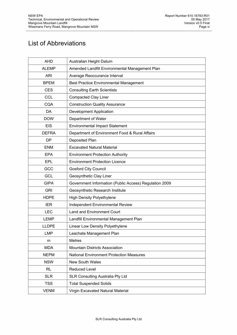
List of Abbreviations
SLR Consulting Australia Pty Ltd
AHD Australian Height Datum
ALEMP Amended Landfill Environmental Management Plan
ARI Average Reoccurance Interval
BPEM Best Practice Environmental Management
CES Consulting Earth Scientists
CCL Compacted Clay Liner
CQA Construction Quality Assurance
DA Development Application
DOW Department of Water
EIS Environmental Impact Statement
DEFRA Department of Environment Food & Rural Affairs
DP Deposited Plan
ENM Excavated Natural Material
EPA Environment Protection Authority
EPL Environment Protection Licence
GCC Gosford City Council
GCL Geosynthetic Clay Liner
GIPA Government Information (Public Access) Regulation 2009
GRI Geosynthetic Research Institute
HDPE High Density Polyethylene
IER Independent Environmental Review
LEC Land and Environment Court
LEMP Landfill Environmental Management Plan
LLDPE Linear Low Density Polyethylene
LMP Leachate Management Plan
m Metres
MDA Mountain Districts Association
NEPM National Environment Protection Measures
NSW New South Wales
RL Reduced Level
SLR SLR Consulting Australia Pty Ltd
TSS Total Suspended Solids
VENM Virgin Excavated Natural Material

NSW EPA Technical, Environmental and Operational Review Mangrove Mountain Landfill Wisemans Ferry Road, Mangrove Mountain NSW
Report Number 610.16783-R01 05 May 2017
Version v0.5 Final Page 1
SLR Consulting Australia Pty Ltd
1 INTRODUCTION
1.1 Outline and Scope
Community members and representatives have raised a number of concerns with the NSW Government and Environment Protection Authority (NSW EPA) about the appropriateness of the Mangrove Mountain landfill facility development and alleged poor management practices at the site. In particular, they are concerned about the potential for negative impacts on the local environment, community and water quality downstream both during operation and into the future.
I, Alan Dyer, on behalf of SLR Consulting Australia Pty Ltd (SLR) was commissioned by the (NSW EPA) to undertake an Independent Environmental Review (IER) of available documentation relating to the landfill design and operation; the proposed landfill expansion; operational management plans; and regulatory considerations in relation to the Verde Terra Facility (Mangrove Mountain Landfill). The review is intended to inform the NSW EPA’s licence review process. The commission was by the NSW EPA at the request of the Mountain Districts Association (MDA).
I am a Technical Director with over 25 years of specialist waste and resource management, community consultation and geotechnical and geological experience within the waste management and quarrying industries, having worked previously for quarry operators, geotechnical contractors and waste management operators, and for the last seventeen years have been in environmental and engineering consulting. I have a Bachelors degree with Honours in Geology, a Masters Degree in Industrial Mineralogy, am a Chartered Environmentalist (CEnv), a Member of the Chartered Institution of Wastes Management (MCIWM), a corporate member of the Waste Management Association of Australia (WMAA), a Member of the Australasian Institute of Mining and Metallurgy (MAusIMM) and Fellow of the Geological Society of London (FGS). I specialise in waste facility design, feasibility, resource assessments and operations support.
The MDA is not-for-profit incorporated association working for the common good of the Mountain Districts and its people. The MDA website quotes ‘the Mountain Districts is an area of the Central Coast of New South Wales, Australia, that includes Mangrove Mountain, Somersby, Central Mangrove, Peats Ridge, Calga, Kulnura, Mount White, Glenworth Valley, Upper Mangrove, Mangrove Creek, Gunderman, Spencer, Greengrove, Lower Mangrove, Bucketty, Murrays Run and Ten Mile Hollow. Its borders are “porous” and it is as much defined by cultural identity and affinity as geography’. The MDA Committee is elected annually.
I have read and considered the following documents/information (listed in reverse chronological order) in the preparation of this IER:
MDA photographic records 2015–2016 for Alan Dyer, received from MDA 9 December 2016.
NSW EPA photographic records 2008–2014 for Alan Dyer, received from MDA 30 November 2016.
Mangrove Mountain Landfill, Hallards Road, Central Mangrove: Landfill Cells X, Y and Z Excavation Preliminary Groundwater Seepage Assessment, document ref: CES110703-VDT-291116, dated 29 November 2016.
Groundwater monitoring data, February 2010 - October 2016; reference CES090607-CMW, undated.
DOW photographic records 2005–2015 for Alan Dyer, received from MDA 30 September 2016.
Part B – Statement of Requirements, NSW EPA, revised 16th September 2016.
Additional Information for Alan Dyer, Mountain Districts Association, dated 14 September 2016.
Landfill Cell W: Filling Plan, Consulting Earth Scientists, document ref: CES110703-VDT-F1, dated 16 June 2016.

NSW EPA Technical, Environmental and Operational Review Mangrove Mountain Landfill Wisemans Ferry Road, Mangrove Mountain NSW
Report Number 610.16783-R01 05 May 2017
Version v0.5 Final Page 2
SLR Consulting Australia Pty Ltd
Hazardous Material Management Plan for the Excavation & Relocation of Material from the Fill Mound, Mangrove Mountain Landfill, Hallards Road, Central Mangrove NSW, Consulting Earth Scientists, document ref: CES110703-VDT-FG, dated 16 June 2016.
Landfill Construction Quality Assurance Plan, Cells W, X, Y, and Z Lot 582, DP 1123656, Hallards Road, Central Mangrove, NSW, Consulting Earth Scientists, document ref: CES110703-VDT-CQA-011113, dated 16 June 2016.
Progressive Capping Plan, Mangrove Mountain Landfill, Hallards Road, Central Mangrove NSW, Consulting Earth Scientists, document ref: CES110703-VT-FJ, dated 16 June 2016.
Quality Assurance / Quality Control Plan: Fill Verification Monitoring Programme – Non Licensed Area. Mangrove Mountain Landfill, Hallards Road, Central Mangrove, NSW, Consulting Earth Scientists, document ref: CES110703-VDT-FH, dated 16 June 2016.
Subsurface Landfill Gas Monitoring Plan, Mangrove Mountain Landfill, Hallards Road, Central Mangrove NSW, Consulting Earth Scientists, document ref: CES110703-VDT-FE, dated 16 June 2016.
Surface & Groundwater Impact Assessment, Mangrove Mountain Landfill, Hallards Road, Central Mangrove NSW, Consulting Earth Scientists, document ref: CES110703-VDT-FD, dated 15 June 2016.
Landfill Environmental Management Plan 2014 (LEMP 2014) Mangrove Mountain Landfill, Hallards Road, Central Mangrove NSW, Consulting Earth Scientists, document ref: CES110703-VDT-FA, dated 14 June 2016.
Leachate Management Plan 2014 (LMP2014), Landfill Cells W, X, Y and Z, Consulting Earth Scientists, document ref: CES110703-VDT, dated 14 June 2016.
Quality Assurance/Quality Control (QA/QC) Plan: Environmental Monitoring Programme, Mangrove Mountain Landfill, Hallards Road, Central Mangrove NSW, Consulting Earth Scientists, document ref: CES110703-VT-QAQC-CC, dated 14 June 2016.
Soil and Water Management Plan, Mangrove Mountain Landfill, Hallards Road, Central Mangrove NSW, Consulting Earth Scientists, document ref: CES110703-VDT-FC, dated 14 June 2016.
Environmental Guidelines: Solid Waste Landfills – Second Edition, NSW EPA, dated April 2016.
Request for a Commission of Enquiry into Mangrove Mountain Golf Course Remodelling and Landfill Project Development Consent DA 23042/1998 for Lot 582 DP 1123656, Mountain Districts Association, dated 29 January 2016.
Media release, Stephen Goodwin, Mountain Districts Association Landfill Subcommittee, dated 12January 2016.
Court Order, Case Number 40900 of 2012 Gosford City Council v Verde Terra Pty Limited, dated 10 November 2014.
Heads of Agreement, Gosford City Council v Verde Terra Pty Limited, Case Number 40900 of 2012, dated 10 November 2014, Land and Environment Court of NSW.
Summary of monitoring data for the chemicals arsenic and hexavalent chromium from the Mangrove Mountain golf course waste landfill site 2001-2014.
Development Consent – Development Application No. 23042 – Proposed Remodelling of Golf Course on Lot 584 DP 809570 Wisemans Ferry Road, Mangrove Mountain, Gosford City Council dated 6 October 1998.
Mangrove Mountain Golf Course Remodelling, Landfill Environmental Management Plan, Perram & Partners, dated March 1997.
Environmental Impact Statement for the Reconstruction of the Mangrove Mountain Memorial Golf Course, Central Mangrove, T.G.T Consulting Services Pty Ltd, dated 14 October 1992.
Protection of the Environment Operations Act 1997 No. 156, Section 45.

NSW EPA Technical, Environmental and Operational Review Mangrove Mountain Landfill Wisemans Ferry Road, Mangrove Mountain NSW
Report Number 610.16783-R01 05 May 2017
Version v0.5 Final Page 3
SLR Consulting Australia Pty Ltd
Environmental Guidelines: Solid Waste Landfills – NSW EPA, dated January 1996.
Discussion Paper on the actions of the former Gosford City Council in the matter of Gosford City Council v Verde Terra Pty Ltd and others – Mountain Districts Association, undated.
1.2 Key Objectives
The key objectives of the review were outlined after agreement between the NSW EPA and the MDA in a meeting dated 14th September 2016. The requirements of the scope are as follows:
‘To advise the EPA and MDA (the Community) on the suitability of the proposed management controls and monitoring framework for the Verde Terra landfill expansion, and of the management controls and compliance with regards to the previous landfill activity, in the context of protecting the environment and the community’.
Specifically:
1. To consult with the EPA and the Community in all stages of the Independent Environmental Review (the Project), and in particular, on any issue impacting on progress with the Project that may require further consultation before proceeding. Approximately fortnightly teleconferences.
2. Prior to commencement of the Project, to meet with the EPA and the Community to discuss the Statement of Requirements and its delivery.
3. Review the Landfill Environmental Management Plan (LEMP), Leachate Management Plan (LMP) and the Soil and Water Management Plan for the Mangrove Mountain Landfill Landfill at Central Mangrove, particularly cell construction for future cells, leachate, groundwater and soil/water management and compliance measures, site management procedures and compliance measures, and ground and surface water monitoring plans and compliance measures. This included checking the adequacy of the number, location and frequency of sampling for the proposed groundwater monitoring bores in adequately monitoring the groundwater aquifers.
4. Review historical information where available on the construction and filling of the landfill to date, including the following:
lining of the area where waste is landfilled, particularly in relation to edges of lined areas for tying in.
past ground and surface water monitoring results with regard to the Australian Drinking Water Guidelines.
information relating to the impact of past activities on existing water courses and groundwater sources.
5. Review the size, location and potential environmental impacts of the site for its suitability for the purpose of functioning as a regional waste facility in an environmentally sensitive area.
6. Assess the proposal and historical landfill against requirements s45(b, c, d, (f1), and (i)) of the POEO Act and against the requirements for the site to function as a landfill for acceptance of general solid waste (non-putrescible) in an environmentally and operationally safe manner acceptable to the EPA and the Community.
7. Prepare a report for the EPA and the Community outlining the findings of the assessment. Where shortcomings against the requirements of s45 (if any) are identified in the proposed management controls and monitoring frameworks, provide recommendations on how these could be addressed.
8. When preparing the report specifically consider and address whether or not:
a. The historical landfill leachate control and management is adequate for the 500,000 tonnes of waste incorporated into the 800,000 m3 of landfill currently on site. To be conservative, assume that lining of currently landfilled area other than Cell 1b is variable to none, and assume a small proportion of landfilled waste was putrescible.

NSW EPA Technical, Environmental and Operational Review Mangrove Mountain Landfill Wisemans Ferry Road, Mangrove Mountain NSW
Report Number 610.16783-R01 05 May 2017
Version v0.5 Final Page 4
SLR Consulting Australia Pty Ltd
b. The proposed leachate holding pond has sufficient design capacity to contain the leachate generated from the existing 800,000 m3 of waste and the additional 1,317,503 m3 of waste.
c. The placement of future waste over historical landfill requires any additional controls.
d. The management of all overland stormwater is guaranteed not to overflow into any future active waste cell, nor into the leachate holding pond, nor off site without first being contained and analysed.
e. The integration and placement of waste into the existing drain/watercourse on the northern side of Cell W has been adequately planned.
f. In the later stages of the project that the temporary storage, placement and stockpile of Virgin Extracted Natural Material (VENM) on site to be used as daily cover material and final capping has been adequately planned.
The following table refers to sections where the scope requirements are covered.
Table 1 Scope Requirement Reference Summary
Scope Ref. Detail Report Section
1 To consult with the EPA and the Community in all stages of the Independent Environmental Review (the Project), and in particular, on any issue impacting on progress with the Project that may require further consultation before proceeding. Approximately fortnightly teleconferences.
N/A
2 Prior to commencement of the Project, to meet with the EPA and the Community to discuss the Statement of Requirements and its delivery
N/A
3 Review the Landfill Environmental Management Plan (LEMP), Leachate Management Plan (LMP) and the Soil and Water Management Plan for the Mangrove Mountain Landfill at Central Mangrove, particularly
cell construction for future cells,
leachate,
groundwater and soil/water management and compliance measures, site management procedures and compliance measures,
ground and surface water monitoring plans and compliance measures,
adequacy of the number, location and frequency of sampling for the proposed groundwater monitoring bores in adequately monitoring the groundwater aquifers.
2
2.3.8, 2.3.9.2, 2.10
2.3.2, 2.3.3 2.3.9.1 2.9, 3, 4
4.4, 4.4.2
4.3, 4.4
4 Review historical information where available on the construction and filling of the landfill to date, including the following:
lining of the area where waste is landfilled, particularly in relation to edges of lined areas for tying in.
a review of past ground and surface water monitoring results with regard to the Australian Drinking Water Guidelines
a review of information relating to the impact of past activities on existing water courses and groundwater sources
6, 7
2.1, 2.2, 2.3, 2.6, 2.7,2.8
6
6
5 Review the size, location and potential environmental impacts of the site for its suitability for the purpose of functioning as a regional waste facility in an environmentally sensitive area.
5
6 Assess the proposal and historical landfill against requirements s45(b, c, d, (f1), and (i) ) of the POEO Act and against the requirements for the site to function as a landfill for acceptance of general solid waste (non-putrescible) in an environmentally and operationally safe manner acceptable to the EPA and the Community.
8

NSW EPA Technical, Environmental and Operational Review Mangrove Mountain Landfill Wisemans Ferry Road, Mangrove Mountain NSW
Report Number 610.16783-R01 05 May 2017
Version v0.5 Final Page 5
SLR Consulting Australia Pty Ltd
7 Prepare a report for the EPA and the Community outlining the findings of the assessment. Where shortcomings against the requirements of s45 (if any) are identified in the proposed management controls and monitoring frameworks, provide recommendations on how these could be addressed.
1-9
8 When preparing the report specifically consider and address whether or not:
The historical landfill leachate control and management is adequate for the 500,000 tonnes of waste incorporated into the 800,000 m3 of landfill currently on site. To be conservative, assume that lining of currently landfilled area other than Cell 1b is variable to none, and assume a small proportion of landfilled waste was putrescible.
The proposed leachate holding pond has sufficient design capacity to contain the leachate generated from the existing 800,000 m3 of waste and the additional 1,317,503 m3 of waste.
The placement of future waste over historical landfill requires any additional controls.
The management of all overland stormwater is guaranteed not to overflow into any future active waste cell, nor into the leachate holding pond, nor off site without first being contained and analysed.
The integration and placement of waste into the existing drain/watercourse on the northern side of Cell W has been adequately planned.
In the later stages of the project that the temporary storage, placement and stockpile of VENM on site to be used as daily cover material and final capping has been adequately planned.
2.1, 2.2, 2.8
2.10
2.8
3
2.7
7.2.5
1.3 Site Location
The site is located in the Central Coast local government area which was formerly a part of the Gosford City Council (GCC) local government area. The site is accessed via Hallards Road, Central Mangrove, NSW. Mangrove Mountain Golf Course has a frontage to Wisemans Ferry Road and also has a vehicular access from Hallards Road.
The landfill sits within the Ourimbah Creek catchment on the NSW Central Coast. Water from the catchment area with the landfill flows through a state conservation area, a rural residential area, then is extracted from Ourimbah Creek approximately 15 kilometres downstream from the landfill facility to supplement the region’s drinking water supply.
1.4 Background
The current landfill is owned and operated by Verde Terra Pty Ltd (Verde Terra) under Development Consent 23042 dated 6 October 1998, the Land and Environment Court (LEC) proceedings 12/40900 Consent Orders dated 29 August 2014 and Environmental Protection Licence (EPL) number 11395 issued by the NSW EPA dated 21 November 2001. The current EPL extends only across the north-western portion of Lot 582 Deposited Plan (DP) 1123656. Lot 582 is proposed to be re-modelled by Verde Terra to provide a new golf course.
In 1974, the site was first developed as an eighteen-hole golf course, but in 1977 was reduced to nine holes.

NSW EPA Technical, Environmental and Operational Review Mangrove Mountain Landfill Wisemans Ferry Road, Mangrove Mountain NSW
Report Number 610.16783-R01 05 May 2017
Version v0.5 Final Page 6
SLR Consulting Australia Pty Ltd
Consulting Earth Scientists (CES) state in their 2016 LEMP that in the early 1990’s the leaseholder of the golf course, Mangrove Mountain Memorial Club, sought a means of reconstructing the course to provide an improved 18-hole layout. The Club gave approval for G & H Todd Pty Ltd to submit a development application to upgrade the course. The development application, accompanied by an Environmental Impact Statement (prepared by TGT Consulting Services Pty Ltd (1992)), and Landfill Environmental Management Plan (prepared by Perram & Partners 1997) was submitted to the then Gosford City Council (GCC) on 16 March 1998.
Development Consent number 23042 for the remodelling of the golf course was granted by the former GCC on 06 October 1998 (Consent). The Consent allows for certain types of waste to be disposed in specified areas at the Site, subject to a number of conditions. The Consent identifies the following documents:
1. Landfill Environmental Management Plan prepared by Perram and Partners (LEMP 1997) (see condition 1 of the Consent), as amended.
2. Environmental Impact Statement (EIS) prepared by T.G.T. Consulting Services Pty Ltd (see Condition 2 of the Consent).
The Mangrove Mountain landfill facility commenced operation in 2001 under the 1998 Development Consent (allowing the placement of 80,000 m3 of fill within a regulated location identified as Area B), and an Environment Protection Licence (EPL) issued by the NSW EPA. NSW EPA records show that, in 2016, over 500,000 tonnes of waste has been landfilled to date at the site.
In 2012, the former GCC commenced proceedings (proceedings number 40900 of 2012) against the operators Verde Terra Pty Ltd and Mangrove Mountain Landfill Pty Ltd in the LEC of NSW due to differing views on the interpretation of the Development Consent, the LEMP and the EIS with the former GCC alleging that Verde Terra was operating in breach of the development consent.
Proceedings in the LEC of NSW were resolved by Consent Orders on 29 August 2014. The terms of those Orders are set out below:
‘Development Consent DA23042/1998 for the landfill and proposed remodelling of the Mangrove Mountain Golf Course on Lot 584 DP809570, Wiseman's Ferry Road, Mangrove Mountain shall be carried out in accordance with the following and pursuant to s.124 of the Environment Planning & Assessment Act 1979 (as amended):
1. The first and third respondents are to comply with the terms of the Amended Landfill Environmental Management Plan 2013 prepared by Consulting Earth Scientists (CES110703-VDT-AR) (“the Amended LEMP 2013”) subject to order 4 below.
2. The first and third respondents are to comply with the terms of the Leachate Management Plan 2013 prepared by Consulting Earth Scientists (CES110703-VDT-60) (“the LMP 2013”) subject to order 4 below.
3. The Amended LEMP 2013 and the LMP 2013 referred to in orders 1 and 2 cannot be further altered except to:
a. amend the documents to reflect the consequences for a 6m reduction in the Mound on Area B in lieu of a 7.4m reduction.
b. subject to subparagraph (a), any future amendment will only occur with the consent of Gosford City Council pursuant to operation of the statutory process available under the Environmental Planning and Assessment Act 1979 (or any equivalent replacement statutory scheme in the future).
4. Works to be carried out on the subject land in accordance with the Amended LEMP 2013 and the LMP 2013 be as follows, and subject to the following conditions and timeframes:
a. 6 metres of waste from the fill mound on Area B be moved to Cell W and a 2.4 metre thick permanent final capping be placed thereon to result in a maximum height for the final landform in Area B of RL341.4.

NSW EPA Technical, Environmental and Operational Review Mangrove Mountain Landfill Wisemans Ferry Road, Mangrove Mountain NSW
Report Number 610.16783-R01 05 May 2017
Version v0.5 Final Page 7
SLR Consulting Australia Pty Ltd
b. The removal of waste and capping of the mound on Area B as set out in subparagraph 4.1 shall be completed no later than 31 August 2017 and otherwise in accordance with the Amended LEMP 2013.
c. The time for completion of the golf course and closure of the landfill operation will be 10 years from the date of approval of the lining of Cell W by the Environment Protection Authority of NSW, and the granting of an amended Environment Protection Licence No, 11395 to reflect the content of the Amended LEMP 2013and LMP 2013, whichever last occurs.
d. The contours for the finished level of closure of the landfill and the golf course are set out in the golf course design by McKay & Sons Pty Limited which is Appendix III to the Amended LEMP 2013. The tolerance to the finished levels are plus 0.5 metres and minus 1.5 metres to enable best practice for the golf course design and are to be adjusted to reduce the Mound in Area B by 6 metres not 7.4 metres as shown, such plans to be delivered to all parties.
e. The total amount of VENM and ENM to be placed over the whole of the land outside the Regulated Area to construct the golf course referred to in 4.4 is 1,137,614m3. The operator of the landfill, and constructor of the golf course, shall deliver a survey of the whole of the land to Council and the EPA of NSW every six months until the golf course is completed when a final survey shall be delivered which demonstrates that there is 1,137,614m3 or less of VENM or ENM on the golf course outside the Regulated Area in situ.
f. The number of truck movements permitted in connection with the landfill operation and construction of the golf course will be 55 per day on average, and the operator of the landfill shall report quarterly to Council, on the periods ending 31 March, 30 June, 30 September and 31 December during the operation of the landfill and the construction of the golf course on the number of trucks transporting waste, VENM and ENM on a daily basis.
g. The total volume of waste material imported to the site to achieve the approved golf course design in the 10 years from the date of approval of the lining of Cell W and approval of the amended EPL 11395 will not exceed the volume required to fill 1,317,503 m3 of space available for filling with waste, whether that space comprises void space created by excavations or whether it comprises air space between the existing ground level and finished ground levels (excluding capping)in the Regulated Area in accordance with the approved golf course design.
h. VENM and ENM can be imported to the site for the construction of the golf course to achieve the approved golf course design.
i. No VENM or ENM can be exported off the site.
j. The surveys to be given to the EPA pursuant to EPL no. 11395 shall be delivered to the Council within 7 days of delivery of the survey to the EPA.
A summary of the key elements of the Consent Orders is as follows:
Allow a further 1,317,503 m3 of waste to be landfilled in the licensed area over a further 10-year operating period.
Require the current landfill mound to be reduced by 6m in height.
Allow a total amount of VENM and ENM to be placed over the whole of the land outside the Regulated Area to construct the golf course referred to in 4.4 is 1,137,614 m3.
The number of truck movements permitted in connection with the golf course will be 55 per day on average.
The contours for the finished level of closure of the landfill and the golf course as set out in the design by McKay & Sons Pty Ltd shall have a tolerance to the finished levels of plus 0.5m and minus 1.5m, as adjusted to reduce the Mound in Area B by 6m.

NSW EPA Technical, Environmental and Operational Review Mangrove Mountain Landfill Wisemans Ferry Road, Mangrove Mountain NSW
Report Number 610.16783-R01 05 May 2017
Version v0.5 Final Page 8
SLR Consulting Australia Pty Ltd
The Orders also require the EPA to amend the EPL to comply with the terms of the Amended Landfill Environmental Management Plan 2013 (the Amended LEMP 2013) together with the Leachate Management Plan 2013 (LMP 2013). The Plans cannot be further altered except to:
1. amend the documents to reflect the consequences for a 6m reduction in the Mound on Area B in lieu of a 7.4m reduction, and
2. subject to (a), any future amendment will only occur with the consent of Gosford City Council pursuant to operation of the statutory process available under the EP&A Act 1979 (or any equivalent replacement statutory scheme in the future).
It is understood that after feedback from the EPA on a previous iteration of the plans, CES has completed a revised set of documents dated June 2016 (which are referred to in Section 1.1 of this IER).
2 LANDFILL DESIGN REVIEW
2.1 Landfill Design Overview
Landfills have served a key role in the management of solid wastes and are likely to continue to be an important component of the waste management system, despite a regulatory drive to divert waste away from landfill through encouraging waste avoidance, reuse, recycling and recovery of energy.
The design of a new, or extension to an existing landfill in NSW is undertaken in accordance with the Environmental Guidelines: Solid Waste Landfills – NSW EPA, 2016, and historically, under the earlier 1996 edition. All landfills must also meet the requirements of the Protection of the Environment Operations Act 1997 and the regulations made under that Act.
The design of any leachate barrier (engineered liner) for the base, side walls and final capping and rehabilitation is governed, in part, also by the waste type proposed to be disposed of.
A leachate barrier is an engineered liner system that forms a barrier between underlying groundwater, soil and substrata, and the waste. Capping barriers are constructed upon the trimmed and profiled waste to primarily minimise ongoing storm water infiltration through the waste, resulting in ongoing leachate generation, and any fugitive emissions as a result of continued waste decomposition.
Modern landfills commonly utilise a composite leachate barrier system that incorporates multiple layers of protection. These facilities may typically include up to 1,000mm in thickness of compacted clay with an in situ hydraulic conductivity of less than 1 x 10⁻⁹ metres/second overlain by a high density polyethylene (HDPE) and/or a geosynthetic clay liner (GCL) comprising highly impermeable bentonite clay. Historical landfills typically have a leachate barrier comprising one component, usually clay, or no barrier at all depending on the nature of the emplaced waste.
Capping barrier systems can comprise compacted clay, HDPE, GCLs and other similar low permeability products. With the capping barrier connected to the base and side wall leachate barrier, and the integrity of the barrier maintained, a landfill can be fully contained.
Although landfill leachate barrier technology has improved significantly over the years, it cannot be guaranteed that the development of a landfill, irrespective of how well it is designed, constructed or operated will not impose some impact on the environment.
The landfill engineering of the Mangrove Mountain landfill facility can be broadly divided into three main areas, as follows:
The basal and side slope area of the ‘existing fill mound’ that does not have the benefit of an engineered leachate barrier containment system (Cell 1A).

NSW EPA Technical, Environmental and Operational Review Mangrove Mountain Landfill Wisemans Ferry Road, Mangrove Mountain NSW
Report Number 610.16783-R01 05 May 2017
Version v0.5 Final Page 9
SLR Consulting Australia Pty Ltd
The basal and partial side slope area of the ‘existing fill mound’ that does have the benefit of an engineered leachate barrier containment system (Cell 1B).
The proposed Cells W, X, Y and Z.
2.2 Unlined Cell 1A within the Existing Fill Mound
The intended nature of the wastes to be placed within the ‘existing fill mound’ according to the Perram & Partners LEMP was inert waste. The Environmental Guidelines: Solid Waste Landfills – NSW EPA, dated January 1996, which was applicable at the time, defined inert waste landfill as ‘any landfill that accepts only inert wastes’.
Inert waste landfills were subdivided into two classes:
Class 1 - all inert wastes including stabilised asbestos cement and physically, chemically or biologically fixed, treated or processed waste in accordance with any special requirements that may be set by the EPA.
Class 2 - all inert wastes except stabilised asbestos cement or physically, chemically or biologically fixed, treated or processed waste.
The Environmental Guidelines: Solid Waste Landfills – NSW EPA, 1996 also states that an inert waste landfill does not require a leachate collection system. In response to this, the Perram & Partners LEMP, dated March 1997, section 3.6.5 Leachate Bund states:
Prior to receiving waste, a bund will be created just downslope from the tipping face to collect run-off from occasions when exposed waste is subject to rainfall before it is covered. An inert waste landfill does not require a leachate collection system (EPA, 1996a). The operator will nonetheless arrange for "operational leachate" to be collected in the bunded area where it may be evaporated or used in dust suppression on the site. Operational leachate is rainfall which has come into contact with deposited waste.
The quality of the operational leachate will be controlled by the rigorous waste screening process described in Section 4. The quantity of leachate produced will be a direct result of the volume of clean rainwater which falls on exposed waste or which infiltrates recently covered waste. By progressively shaping, compacting and covering the waste as outlined below, the quantity of leachate produced will be substantially restricted.
For the purposes of this review, it has been assumed, based on available information that up to 85% of the area of the existing fill mound does not have an engineered barrier. Approximately 15% has a composite lined leachate barrier, details of which are covered in Section 2.3.
Although by modern day standards, the lack of an engineered barrier between the waste (and leachate) and the underlying insitu rock would not be appropriate, the site complied with the requirements of the 1996 Guidelines, assuming inert waste to the description defined within the Guidelines was being emplaced.
In assessing the likely risk of the unlined Cell 1A on the environment today, a number of factors need to be considered. These considerations include, but are not limited to the following:
Permeability of the underlying Hawkesbury Sandstone.
Geometry of the underlying landfill basal surface.
Leachate head within the waste mass.
Chemistry of the leachate.
Depth to the underlying groundwater.
Surcharging of the currently emplaced waste.

NSW EPA Technical, Environmental and Operational Review Mangrove Mountain Landfill Wisemans Ferry Road, Mangrove Mountain NSW
Report Number 610.16783-R01 05 May 2017
Version v0.5 Final Page 10
SLR Consulting Australia Pty Ltd
Capping and rehabilitation of the existing fill mound.
This IER presents available information and makes recommendations based on these considerations.
2.2.1 Permeability of the Underlying Hawkesbury Sandstone
CES undertook falling head permeability tests in shallow and deep nested groundwater wells, 2, 3, 6, 7 and 8 at the site during August 2016. The tests were conducted in accordance with CES Standard Operating Field Procedures and BS5930 Code of practice for Ground Investigations. The tests were undertaken to estimate Hydraulic Conductivity (K), also referred to as permeability. Results of testing, presented within document titled Mangrove Mountain Landfill, Hallards Road, Central Mangrove: Landfill Cells X, Y and Z Excavation Preliminary Groundwater Seepage Assessment, document ref: CES110703-VDT-291116, dated 29 November 2016, show the average hydraulic conductivity to be low with results in the order of 1x10⁻⁶ m/s for the shallow and deep nested wells.
These data indicate that the permeability of the underlying Hawkesbury Sandstone is lower than might be expected for a medium to coarse grained sandstone.
A certain degree of additional impermeability will likely be afforded to the sandstone surface by biological clogging and silt/fines deposition derived from the emplaced waste mass and leachate. Much research has been undertaken on biological clogging and silting up of landfill bases, which is known to restrict fluid pathways, in this instance likely having some impact in retarding leachate movement from the waste into the underlying sandstone.
I recommend that additional Hawkesbury Sandstone permeability testing is undertaken within each of the proposed groundwater monitoring boreholes as soon as practicable after the installation1. Data recorded from each borehole should be used to update the groundwater model. Fresh boreholes will not be impacted by possible silting up and biological clogging of the sandstone that may be an issue with undertaking permeability testing on existing monitoring bores.
It is noted that environmental monitoring of ground and surface waters has not shown any evidence of leachate contamination to date, however, as recommended within this IER, the current groundwater monitoring network should be further improved.
2.2.2 Geometry of the Underlying Landfill Basal Surface
It is understood that Cell 1A was not deeply excavated, with waste placed within a shallow excavation. Without the benefit of a recessed void to fill with supporting side walls, there may be concerns with waste mass stability due to settlement or subsequent waste surcharging along the northern and western boundary of the existing fill mound. This matter is covered further in this IER.
It is further understood through discussions with Consulting Earth Scientists (CES) in February 2017, in the presence of the NSW EPA, that Cell 1A (certainly in the vicinity of the proposed Cells X and Y) has a trimmed floor that may allow leachate to flow south and east from the fill mound and be collected in a proposed leachate collection trench. However, there are no historic supporting photographs or as-constructed survey plans to validate these claims.
2.2.3 Leachate Head Within the Waste Mass
There is no physical recorded level data available for review on the level of leachate within the existing fill mound. Cell 1B drains under gravity (if unimpeded) to the north-east whereby it exits via an extraction pipe to a leachate collection dam. This IER makes recommendations within Section 2.9 for leachate monitoring wells to be installed in order to allow a comparison of levels to licensed limits and to monitor the impact of waste overtipping from proposed Cells W, X and Y on leachate basal levels.
1 Table 3 Recommendation 1

NSW EPA Technical, Environmental and Operational Review Mangrove Mountain Landfill Wisemans Ferry Road, Mangrove Mountain NSW
Report Number 610.16783-R01 05 May 2017
Version v0.5 Final Page 11
SLR Consulting Australia Pty Ltd
2.2.4 Remaining Considerations
Remaining considerations are dealt with elsewhere within this IER.
The IER makes recommendations for early capping and rehabilitation of as much of the existing fill mound as possible to significantly reduce leachate inflows and the subsequent ongoing generation of leachate.
On balance, whilst there is a larger risk of leachate moving through the base of the existing fill mound compared to proposed composite lined engineered Cells W, X, Y and Z, in the absence of a proposal to completely remove the existing fill mound waste mass, the proposals and recommendations made within this IER in respect to the CES reports and concept design drawings provide a practical and achievable approach to managing the risks.
2.3 Lined Landfill within the Existing Fill Mound - Cell 1B
Photographic information provided by the MDA, as a result of a Government Information (Public Access) Regulation 2009 (GIPA) request to the NSW EPA, shows the sequential construction of Cell 1B within the ‘existing fill mound’ between March and April 2009. The photographic evidence shows the following construction layering in top-down order:
150mm layer of crushed sandstone.
Geotextile layer.
Leachate drainage blanket and recessed leachate collection pipework.
Needle punched non-woven geotextile.
High Density Polyethylene (HDPE) geomembrane liner (appears to be untextured).
Geosynthetic Clay Liner (GCL).
Needle punched non-woven geotextile.
Trimmed subgrade.
Photos 1 and 2 below show the engineered lining of the base and steep north-west and south-east side walls, over an irregular rock side wall subgrade beneath the covering protection geotextile.
Photo 1 Lower protection geotextile and overlying GCL on steep south-west trimmed flank
NSW EPA Technical, Environmental and Operational Review Mangrove Mountain Landfill Wisemans Ferry Road, Mangrove Mountain NSW
Report Number 610.16783-R01 05 May 2017
Version v0.5 Final Page 12
SLR Consulting Australia Pty Ltd
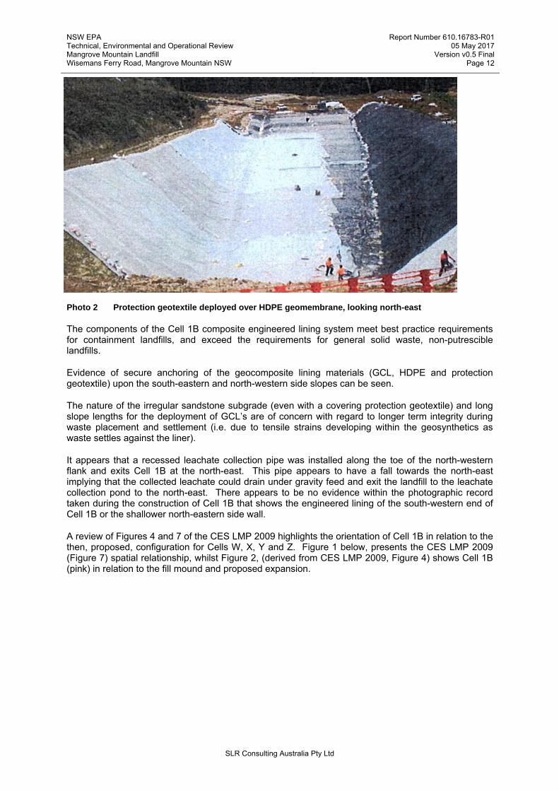
Photo 2 Protection geotextile deployed over HDPE geomembrane, looking north-east
The components of the Cell 1B composite engineered lining system meet best practice requirements for containment landfills, and exceed the requirements for general solid waste, non-putrescible landfills.
Evidence of secure anchoring of the geocomposite lining materials (GCL, HDPE and protection geotextile) upon the south-eastern and north-western side slopes can be seen.
The nature of the irregular sandstone subgrade (even with a covering protection geotextile) and long slope lengths for the deployment of GCL’s are of concern with regard to longer term integrity during waste placement and settlement (i.e. due to tensile strains developing within the geosynthetics as waste settles against the liner).
It appears that a recessed leachate collection pipe was installed along the toe of the north-western flank and exits Cell 1B at the north-east. This pipe appears to have a fall towards the north-east implying that the collected leachate could drain under gravity feed and exit the landfill to the leachate collection pond to the north-east. There appears to be no evidence within the photographic record taken during the construction of Cell 1B that shows the engineered lining of the south-western end of Cell 1B or the shallower north-eastern side wall.
A review of Figures 4 and 7 of the CES LMP 2009 highlights the orientation of Cell 1B in relation to the then, proposed, configuration for Cells W, X, Y and Z. Figure 1 below, presents the CES LMP 2009 (Figure 7) spatial relationship, whilst Figure 2, (derived from CES LMP 2009, Figure 4) shows Cell 1B (pink) in relation to the fill mound and proposed expansion.

NSW EPA Technical, Environmental and Operational Review Mangrove Mountain Landfill Wisemans Ferry Road, Mangrove Mountain NSW
Report Number 610.16783-R01 05 May 2017
Version v0.5 Final Page 13
SLR Consulting Australia Pty Ltd
Figure 1 CES LMP 2009 (Figure 7) showing the then, Cell W, X, Y and Z configuration
Figure 2 CES LMP 2009 (Figure 4) showing Cell 1B (pink) in relation to the fill mound and proposed
expansion

NSW EPA Technical, Environmental and Operational Review Mangrove Mountain Landfill Wisemans Ferry Road, Mangrove Mountain NSW
Report Number 610.16783-R01 05 May 2017
Version v0.5 Final Page 14
SLR Consulting Australia Pty Ltd
Photo 3 Placed crushed sandstone within near completed Cell 1B, showing unlined south-west wall, looking south-west
Photo 3 shows the placed (or partially placed) 150mm of crushed sandstone above the Cell 1B basal protection geotextile and GCL/HDPE. The image shows that the south-western end of the cell was not lined. It is assumed that the design for Cell 1B proposed that the south-western wall would at some point be excavated down to the floor level of Cell 1B whilst making a connection to the future Cell Z.
The south-west connection now aligns to the proposed Cell X in the CES LMP 2016 configuration.
CES have not provided engineering details regarding any connection between the proposed Cell X and the existing Cell 1B south-western wall. It appears clear from Figure 4 of CES LMP 2016 that the north-western wall of the proposed Cell X does not intend to tie into unlined sections of Cell 1B. Furthermore, it appears that the position of the Cell 1B south-western wall has now been buried in waste that forms the eastern side slope of the existing fill mound. I deduce from the above that the south-western wall and the north-eastern edge of Cell 1B intends to remain unchanged (unlined) in the proposed CES designs.
The north-eastern end of Cell 1B should allow leachate collected in the basal drainage to drain out of the horizontal leachate extraction pipe that feeds the current leachate dam. Additional details of any retention bund or engineered barrier would be useful in determining whether the northern end of Cell 1B poses an environmental risk.
The concern of Cell 1B not being lined at either the south-western or north-eastern end however needs to be considered in the context of the remaining base and side slopes of the existing fill mound not appearing to be lined either. The impact of the unlined sections of Cell 1B alone may add to the estimate of the basal surface percentage unlined, but proportionately little.
With these two ends of Cell 1B ‘open’ I recommend that Verde Terra provide design details to the NSW EPA of the proposed (if any) connection between the proposed Cell X and the current Cell 1B south-western wall2.
2 Table 3 Recommendation 2

NSW EPA Technical, Environmental and Operational Review Mangrove Mountain Landfill Wisemans Ferry Road, Mangrove Mountain NSW
Report Number 610.16783-R01 05 May 2017
Version v0.5 Final Page 15
SLR Consulting Australia Pty Ltd
2.4 Proposed Cells W, X, Y and Z
Verde Terra engaged CES to prepare a landfill design for Cells W, X, Y and Z which was intended to provide a basis for development of a comprehensive engineered lining system. The proposed design is presented within the Leachate Management Plan 2014 (LMP 2014), dated 14 June 2016. The lining system proposed incorporates a composite lined engineered barrier and leachate collection infrastructure which largely meets best practice requirements and the Environmental Guidelines, Solid Waste Landfills, NSW EPA 2016.
The proposed design incorporates the following construction layering in top-down order:
Protective padding sand (300mm thick).
Triplanar Geonet.
Upper protective geotextile layer (Bidim A64 or equivalent with minimum 500mm overlap).
HDPE Geomembrane (seams to be thermally welded).
Geosynthetic Clay Liner (GCL) (overlap to be a minimum of 12% of roll width).
Lower protective geotextile layer (Bidim A64 or equivalent with minimum 500mm overlap).
Cell floor/wall.
The CES landfill design has two primary containment components, a relatively flat lying basal engineered layer, and secondly, steep quarry side walls (LMP Figures 4-7). Even though the excavated side walls are significantly steeper than the base, CES propose a similar engineered containment approach.
The construction (and subsequent filling) sequence is from Cell W in the north-east to Cell Z in the south-west. The four cells shall be in hydraulic continuity so that all leachate collected in the base of the cells shall, by gravity, migrate to a proposed exit point within Cell W through a triplanar geonet and a series of recessed perforated HDPE pipes.
The lowest Reduced Level (Reduced Level in surveying refers to equating elevations of survey points with reference to a common assumed datum (RL)) is designed to be at 292m, some 1m below the proposed leachate transfer pipe that allows leachate to exit the landfill and flow to the proposed leachate holding pond (LMP Figure 4). The highest basal elevation (taken from leachate pipe levels) within Cell Z is RL 298.4m. Corresponding proposed final landform contours (LMP Figure 5) show levels ranging from RL 323m at the lowest point in Cell W, to RL 340m in the south-west of proposed Cell Z. A simple comparison of levels between the RL’s shown for the top of the leachate pipework (LMP Figure 4) and the proposed final landform contours (LMP Figure 5) indicate a waste depth of between approximately 31m (Cell W) and 42m (Cell Z).
The composite lining system proposed for the base and side walls is typical of many modern municipal solid waste (MSW) landfills constructed in well developed countries and generally complies with Environmental Guidelines: Solid Waste Landfills – Second Edition, NSW EPA, 2016, the QLD Guidance DERM – Guideline ERA75 Environmental Protection Regulation 1998: Landfill Siting, Design, Operation & Rehabilitation and the VIC EPA Best Practice Environmental Management (BPEM), in terms of lining and leachate extraction components used in a base lining system of a landfill.
Minimum requirements, based on the Environmental Guidelines: Solid Waste Landfills – Second Edition, NSW EPA, 2016 from the top down are as follows:
High durability nonwoven geotextile for separation and filtration.
A coarse no-fines 300mm aggregate leachate collection system complimented by a network of collection pipes at 25m centres.
High durability nonwoven geotextile cushion to protect the geomembrane.

NSW EPA Technical, Environmental and Operational Review Mangrove Mountain Landfill Wisemans Ferry Road, Mangrove Mountain NSW
Report Number 610.16783-R01 05 May 2017
Version v0.5 Final Page 16
SLR Consulting Australia Pty Ltd
A 2mm HDPE geomembrane.
A one metre (minimum) compacted clay liner (CCL).
A minimum 200mm compacted subgrade to provide a stable working platform for the CCL.
A GCL is deemed a suitable replacement to a CCL in certain circumstances, such as the lack of availability of suitable clay.
The following sections review the engineered components proposed by CES, areas of concern and their suitability for their application.
2.4.1 Subgrade Surface
The design subgrade is a trimmed Hawksbury Sandstone base and side walls. Cell W has been shaped to have long steep side slopes to a graded floor towards the north-east (currently under water).
The design configuration and geometry for Cells X, Y and Z includes the provision of benched side walls to facilitate construction of the leachate barrier. The proposed benches are typically 2m wide and 5m in height. CES state that the design configuration is presented within Figure 4: Landfill Cell Footprints, Configuration and Location of Leachate Holding Pond (CES LMP June 2016), although the benching is not clear. It is Recommended that by creating an inward facing gradient to the excavated side wall benches in the proposed Cells X, Y and Z and profiling the bench apex can increase drainage of leachate from the benches to the collection and extraction infrastructure below.3
Furthermore, the connection between a steep sided Cell W and benched Cell X is not covered in any detail. CES have provided a ‘conceptual sketch’ of the likely detail during discussions with the NSW EPA in February 2016. It is recommended however, that additional detailed design details are provided to the NSW EPA for this complicated tie in4.
There is limited detail on the subgrade connection between the proposed Cells W, X, Y and Z with the existing Cell 1B side wall and remaining Cell 1A further to the south-west within the existing fill mound, further details are required in the detailed design submission5. Additional detail of the Cell X, Y and Z benching is required to understand the staged anchoring of the geosynthetics and connection to subsequent lifts/stages6. Detail of the degree of rounding of the rock bench corners to minimise stressing of the overlying GCL and stress cracking of the HDPE should also be provided to the NSW EPA for review7.
It is noted (on CES LMP - Figure 7: Leachate Collection Pipe, Pipe Penetration Detail and Sump Design) that the subgrade is recessed (2.5m x 2.5m x 1m) at the lowest point of Cell W. This recess is designed as a leachate sump with its base 2m below the invert level of the exiting leachate transfer pipe. This design contradicts Section 6 Leachate Management Strategy, item c that states ‘the leachate management strategy for the landfill area of the site is based on the following principles Control and minimise leachate head to a level no greater than 1m above the landfill liner’.
It is noted that Section 1.9 of the Environmental Guidelines: Solid Waste Landfills – Second Edition, NSW EPA, 2016 states that the leachate extraction and level-control system should:
3 Table 3 Recommendation 3 4 Table 3 Recommendation 4 5 Table 3 Recommendation 5 6 Table 3 Recommendation 6 7 Table 3 Recommendation 7

NSW EPA Technical, Environmental and Operational Review Mangrove Mountain Landfill Wisemans Ferry Road, Mangrove Mountain NSW
Report Number 610.16783-R01 05 May 2017
Version v0.5 Final Page 17
SLR Consulting Australia Pty Ltd
Be able to keep the leachate level no greater than 300 millimetres above the upper surface of the base liner, or below some other level that is justified by the design, site conditions and leachate management measures (note: the flow of leachate through the liner is greater when leachate is allowed to accumulate within the cell, and higher leachate levels can also interfere with landfill gas controls).
Noting that a 1m head was agreed through the Consent orders process, I recommend that CES consider removing the sump recess, with additional sump capacity designed above the landfill base by means of a <1m high mound or platform of granular material, connected to the extraction riser that will allow leachate to collect and assist locally with gravity drainage8.
2.4.2 Groundwater Under-Cell Drainage
The CES LMP June 2016, Section 8 states that ‘no significant groundwater that could impact on the installation of the leachate barrier in Cell W has been observed, however it is likely that groundwater will be encountered as excavation proceeds in a south westerly direction during construction of Cells X, Y and Z and groundwater depressurisation measures will be required’.
By comparing the Table 3: Summary Groundwater Data (CES LMP June 2016) with Figure 4 (CES LMP June 2016) an approximate correlation of groundwater level to proposed RL of Cells W, X, Y and Z can be estimated, as follows:
Table 2 Comparison of Groundwater Levels to Proposed Landfill Extension Base RL’s
Stage Monitoring well reference
Table 3
Median Standing Water Level (SWL) (mAHD)
Table 3
Lowest Basal Design Level
Figure 4
Column A Column B
Cell W 8AS 8AD
300.68 295.82
292
Cell X None - -
Cell Y 7AS
7AD
Dry
297.93
294.25
Cell Z None - -
Note: Cells X and Z do not have a nearby monitoring bore for reference
By comparing the SWL data in Column A above with Figure 4: Landfill Cell Footprints, Configuration and Location of Leachate Holding Pond (CES LMP June 2016) levels (Column B), an estimate of the groundwater level compared to the base level can be made. The RL’s given for the lowest mid-point main spine leachate collection pipe for Cell W is RL 292m and for Cell Y is RL 294.25m. Using this design information, the proposed Cell W leachate collection spine appears to be approximately 3.8m to 8.6m below the median ground water table, while for the proposed Cell Y the leachate spine is 3.7m below groundwater level.
During discussions with the author and the NSW EPA in February 2017, CES presented a letter report titled Mangrove Mountain Landfill, Hallards Road, Central Mangrove: Landfill Cells X, Y and Z Excavation Preliminary Groundwater Seepage Assessment, dated 29 November 2016 for consideration. The report provides useful information on monitored groundwater levels, rock permeability and anticipated seepage rates, primarily within Cells X, Y and Z. Table 1 within the document provides elevations to standing water (groundwater levels) in mAHD (i.e. more recent monitoring results than those presented in Column A in Table 2 above). The groundwater in shallow nested well 8AS is presented as 299.3mAHD, whilst deep nested well 8AD is 293mAHD. which again indicate that Cell W groundwater is above the proposed leachate central spine levels for the entire Cell W. 8 Table 3 Recommendation 8

NSW EPA Technical, Environmental and Operational Review Mangrove Mountain Landfill Wisemans Ferry Road, Mangrove Mountain NSW
Report Number 610.16783-R01 05 May 2017
Version v0.5 Final Page 18
SLR Consulting Australia Pty Ltd
For these reasons, I do not agree with CES LMP Section 5.1, which states ‘groundwater inflow will be minimal due to the landfill cell base being excavated to elevations above groundwater level and the installation of a leachate barrier’.
It states in CES LMP June 2016, Section 3.5, ‘minor perched water seepages have been observed from above Shale lenses in the Cell W excavation side wall, however significant inflows of groundwater have not been observed in the excavation that would adversely impact on the installation or performance of the leachate barrier or leachate collection and conveyance system proposed for Cell W’.
Furthermore, it states however that ‘in consideration of the fine grained nature of the Sandstone encountered in the Cell W excavation and observed in boreholes at the site and along the access road cutting in the south west of the site and the presence of interbedded and interlaminations and lenses of shale and the absence of significant joints or defects, it is anticipated that groundwater depressurisation below the leachate barrier of Cell X, Y and Z will be manageable using simple measures’.
I recommend that Verde terra provide a detailed three-dimensional groundwater model to the NSW EPA as part of the detailed design submission for Cell W. The model should consider seasonal groundwater variations to ascertain the minimum, median and maximum ground water levels within the Cell W, X, Y and Z footprint9.
The proposed outline design philosophy for the construction of subfloor groundwater depressurisation drains is sound. CES propose to excavate shallow trenches (approximately 0.75m wide by 0.5m deep) and install slotted pipe and backfill with coarse aggregate and a geotextile separation layer placed over the aggregate. To collect and remove the groundwater, CES suggest that the drainage pipe would fall to a collection sump or riser pipe.
The placement of a groundwater extraction side riser, recessed into a steep sandstone face (or benches in the case of Cells X, Y and Z) will be challenging, and will likely need to be undertaken in stages as waste lifts progress upwards.
CES state that the detailed design for a groundwater depressurisation system would be undertaken as part of the installation works for the additional groundwater monitoring wells to be installed at the site.
In consideration of the above base levels and SWL data, it is recommended that subfloor groundwater depressurisation drains be considered for Cell W also10. Detailed specifications for the groundwater pipework are required, with calculations to demonstrate that they will remain undeformed during their serviceable life11. Typically, groundwater drainage pipework is recessed into the base of the landfill subgrade within shallow trenches, such that the trenches may provide protection against pipe deformation or failure.
If the installation of groundwater relief drains within Cell W are chosen not to be installed, the design base levels for Cell W could be raised. Careful consideration on the cut-fill balance would need to be reviewed in this instance.
The presence of uncontrolled groundwater seepages into the proposed Cell W construction area may lead to basal uplift of the engineered components due to hydrostatic pressure, and result in difficulties in construction, risk of groundwater contamination from construction plant activities and premature hydration of the proposed GCL.
9 Table 3 Recommendation 9 10 Table 3 Recommendation 10 11 Table 3 Recommendation 11

NSW EPA Technical, Environmental and Operational Review Mangrove Mountain Landfill Wisemans Ferry Road, Mangrove Mountain NSW
Report Number 610.16783-R01 05 May 2017
Version v0.5 Final Page 19
SLR Consulting Australia Pty Ltd
It is acknowledged that groundwater collected by any depressurisation system would be collected and conveyed to a storage tank. CES propose that the groundwater quality testing will be undertaken and depending upon results the water will be either discharged into the creek (only where concentrations of Total Suspended Solids (TSS) are less than 50 mg/l and ammonia and pH are similar to ambient groundwater quality) at the northern site boundary or pumped into the leachate pond at the site.
2.4.3 Groundwater Side Wall Under-Cell Drainage
With the acknowledged ingress through seepages into the proposed landfill Cells X, Y and Z, the extension of the groundwater depressurisation drains partially up the side walls should be installed up to the level of the known groundwater ingress level. Similar drainage needs to be installed within Cell W also12.
2.4.4 Lower Protective Geotextile Layer
The design of the proposed landfill cells incorporates a 500g/m2 non-woven lower protective geotextile layer (Bidim A64 or equivalent with minimum 500mm overlaps) to protect the overlying GCL and HDPE from installation, waste placement and subsequent waste settlement forces. This will likely be suitable as long as larger irregularities and protrudencies are removed by mechanical means.
2.4.5 Geosynthetic Clay Liner
A GCL is proposed for Cells W, X, Y and Z having a hydraulic conductivity of no greater than 3 x 10-11 m/sec. GCL’s are a recognised acceptable alternative to CCL’s and have been used as an alternative to CCL’s on numerous landfills in NSW. GCL’s are known to have a lower permeability than typical CCL’s.
Section 6.3.3.3 of the CES LMP June 2016 explains that the design configuration and geometry for Cells X, Y and Z is shown on Figure 4 and includes the provision of benched side walls to facilitate the construction of the leachate barrier. The proposed benches are typically 2m wide and 5m in height. The passage continues to state that Cell W is currently excavated and does not possess side wall benches. The details within Figure 4 are very limited, with the aforementioned benches not clear from the drawing. Limited construction details are provided for the engineered lining of the full side slopes of Cells X, Y and Z, and no details for lining of Cell W. I recommend that detailed design drawings with supporting calculations and CQA procedures be provided to the NSW EPA for consideration13.
The deployment of GCL and an overlying HDPE upon a benched side wall may be undertaken in a series of stages or as one complete installation. If undertaken in stages, machine access to deploy the geosynthetic rolls needs to be maintained from each bench above.
The CES LMP June 2016 discusses the installation of the leachate barrier within the existing steeply excavated Cell W. The CES LMP June 2016 states that this may be undertaken either by utilising the top-down installation method or by bottom up installation. During bottom up installation, the leachate barrier components should be installed up the excavation side walls extending the leachate barrier system from the base and the barrier system secured in place at an appropriate elevation.
To assist with the anchoring, the CES LMP June 2016 states that the leachate barrier layers (assumed to be GCL and HDPE) should be secured and held in place using rock dowels comprising 500mm long, 20mm diameter (minimum) galvanised deformed steel bar installed at 2m centres or as required to provide adequate support. The rock dowels should be installed at an angle of -45° (downwards) and adequately grouted in place. The rock dowel should then be passed through holes made through the leachate barrier layers and secured with and a head plate and bolt.
12 Table 3 Recommendation 12 13 Table 3 Recommendation 13

NSW EPA Technical, Environmental and Operational Review Mangrove Mountain Landfill Wisemans Ferry Road, Mangrove Mountain NSW
Report Number 610.16783-R01 05 May 2017
Version v0.5 Final Page 20
SLR Consulting Australia Pty Ltd
The CES LMP June 2016 states ‘As waste filling progresses, the leachate barrier is to be extended further up the excavation side walls. The leachate barrier should be neatly cut at a level below the line of rock dowels and the punctured leachate barrier material discarded. The rock dowels should be removed and the dowel holes backfilled with grout. If the rock dowels cannot be fully removed, a small area of rock should be cut from around the side of the rock dowel to allow the steel bar to be cut. The area of rock excavation should then be made good with mortar. The leachate barrier should then be extended further up the excavation side wall and secured at the next appropriate elevation using a further row of rock dowels. The above procedure should be repeated until, the side walls of the cell are fully lined and the leachate barrier secured in the top of side wall anchor trench’.
It is unclear whether the Cell W leachate barriers (GCL and HDPE) are to be fixed within an anchor trench (as stated within LMP Section 6.3.3.3.1), or whether the barrier layers are to be installed in a series of lifts as detailed in Section 6.3.3.3.3, and outlined above. There would likely be construction issues, and possible materials damage in relation to the initial wall fixing method. The method of GCL installation, and the removal of galvanised steel fixing anchors as the waste lifts arose indicates that no permanent anchoring of the side wall GCL is afforded beneath the fully welded HDPE.
The installation would need secure access from the floor of Cell W (or waste surface as lifts progress), or alternatively, operators working from fixed ropes from above.
There are no construction details within CES LMP 2016 Figure 6 or 7 showing how subsequent side wall barrier lifts are to be secured or constructed and how these connect to any lower bench lining; these need to be addressed. recommend that further details are provided by CES to the NSW EPA on the proposed installation and fixing of side wall geosynthetics in order to undertake a review of appropriateness14.
From a technical standpoint, a GCL is not meant to act as a drapery system but rather it relies on the frictional interaction with the slope, hence the lower the gradient, the better. Deployment of very steep slopes can lead to localised shear failures at the point of anchorage. Consideration needs to be given to the long-term performance of the geosynthetic materials, especially the GCL15.
The design for Cells W, X, Y and Z should, as a minimum consider GRI-GCL5 -Design Considerations for Geosynthetic Clay Liners (GCLs) in Various Applications" Revision 1 (Editorial): January 9, 2013 http://www.geosynthetic-institute.org/grispecs/gcl5.pdf but also be in accordance with Table 1 of the Environmental Guidelines: Solid Waste Landfills – Second Edition, NSW EPA, 2016 (the CES LMP June 2016 Table 7 Geosynthetic Clay Liner Minimum Requirements is currently not compatible).
The mechanical stability of the GCL is mainly influenced by the slope, the confining stress and the interface friction angle with adjacent layers. Additionally, the performance of the GCL is influenced by the elongation performance of the GCL during differential settlement. Internal shear strength should be considered under the low confined stress applications using ASTM D 6243 under site-specific and product-specific conditions. I recommend these data are provided to the NSW EPA as part of the detailed design package.16
The low hydrated mid-plane friction angle of the bentonite alone (peak approx. 9°, residual about 4° to 5°) is overcome by the needle punching of all components creating a uniform shear stress transmitting GCL. It is important to evaluate the interface shear stress of the GCL and prove that the internal shear stress of the GCL is sufficient to meet design criteria.
GCL’s are commonly used in landfill applications with shallower side slopes of typically 4H:1V or in some cases as steep as 2H:1V, rarely in applications such as that proposed for Cell W. CES should consider specifying specific high specification products capable of long-term performance in this scenario, as part of the detailed design submission to the NSW EPA.
14 Table 3 Recommendation 14 15 Table 3 Recommendation 15 16 Table 3 Recommendation 16

NSW EPA Technical, Environmental and Operational Review Mangrove Mountain Landfill Wisemans Ferry Road, Mangrove Mountain NSW
Report Number 610.16783-R01 05 May 2017
Version v0.5 Final Page 21
SLR Consulting Australia Pty Ltd
CES LMP June 2016 Figure 6 (reproduced as Figure 3 below) shows the proposed engineered details for the side wall barrier system and the exiting leachate transfer pipe. There are a number of design concerns that need further detail from CES, as follows:
There is insufficient detail on how the engineered geocomposite leachate barrier is anchored around the leachate transfer pipe. Currently the figure shows it abruptly stop with no detail on how it relates to the bentonite cement seal behind it.
There are a number of very tight corners, and in fact an overhanging section within the proposed sump at the base of the side wall pipe, these areas should show some rounding to minimise damage to the geosynthetics.
The engineered geocomposite leachate barrier does not appear to be secured in any way to the compacted fill at the wall surface.
An indication of slope angle is required.
Detail B appears to be a Plan view but does not detail the engineered barrier system and its relationship to the excavated wall and the pipe system.
Figure 3 Side Wall/Leachate Collection Pipe Detail
Note. Figure reproduced from CES LMP Figure 6
I have concerns with draping panels of GCL from wall fixings on a steep slope for the following reasons:
Difficulty in positioning and fixing GCL panels on a steep, near vertical wall due to a dead weight of 5kg/m2 which should be avoided where possible. Tearing and propagation of tears from the side wall anchor points due to weight particularly when GCL becomes hydrated may be an issue.
Without an anchor trench and by using rock dowels (anchor/fixing bolts) there is a risk of not achieving a water tight seal at the point of anchorage between the geosynthetics and excavated rock wall. With elevated groundwater ingress or stormwater runoff from the above unlined surface being channelled behind the barrier layers, there is risk of pre-hydration of the GCL and build-up of water below the side wall liner, resulting in loading and potential damage to mid slope wall fixings and GCL.

NSW EPA Technical, Environmental and Operational Review Mangrove Mountain Landfill Wisemans Ferry Road, Mangrove Mountain NSW
Report Number 610.16783-R01 05 May 2017
Version v0.5 Final Page 22
SLR Consulting Australia Pty Ltd
The effectiveness of composite lining barrier systems is reliant on the constituent layers being in close contact with each other which is a key reason why landfill side slopes are typically designed to 3(V):1(H) to allow close contact between layering due to self-weight of the materials.
The perforated leachate collection pipe shown in Figure 3 above will likely be constructed in a series of short lifts to enable the crushed padding layer to be placed. Without any means to confine the padding layer, the sand will likely collapse if constructed in longer lifts.
In Cell W, it is recommended that GCL and geotextile materials should have overlaps increased to counteract any elongation/necking, subject to manufacturer considerations17.
Where the above considerations cannot be addressed, I recommend that CES consider all other options for a barrier system for Cell W based on the current cell geometry. A more appropriate configuration may be utilising a compacted clay liner (CCL) as an alternative to a GCL with the overlying HDPE within the floor and lower side slopes of Cell W should be considered18. A CCL floor will help mitigate against the likelihood of basal heave due to the interaction of groundwater ingress, with the CCL placed partially up the side walls also reducing the current steep slope lengths making a GCL more acceptable for the shorter subsequent upper slope lengths.
2.4.6 HDPE Geomembrane
The proposed HDPE geomembrane liner is a 2mm nominal thickness mono-textured HDPE (textured side to GCL layer) for the side walls and a 2mm nominal thickness smooth HDPE being proposed for the cell base. A mono-textured option for the side walls is acceptable as the smooth side against the overlying protection geotextile may reduce strain loading on the HDPE by the placement and subsequent settlement of the buttressing waste. A smooth HDPE on the proposed landfill base may (and has been known to do so) however induce waste mass failure, with waste sliding over the smooth surface in the presence of leachate. I recommend the design consider a double rough HDPE on the base of the landfill as this minimises the risk of waste slope failure by sliding over the protection geotextile/smooth upper surface mono-rough geomembrane interface19.
The CES LMP June 2016 provides HDPE minimum requirements within Table 6. The minimum requirements should be in accordance with Geosynthetic Research Institute (GRI) GM13 - Test Methods, Test Properties and Testing Frequency for High Density Polyethylene (HDPE) Smooth and Textured Geomembranes. All HDPE materials should comply with GRI GM13, this should be clearly stated within an appropriately detailed specification and CQA Plan20.
A composite lining system comprising an HDPE with an underlying GCL is a recognisable combination in modern landfills within NSW.
Like with the GCL previously, there may be installation difficulties in deploying (and welding) the HDPE on the Cell W side slope, especially as GCL’s are to be covered soon after placement to avoid premature hydration. These details need to be clearly outlined within a technical specification and CQA Plan which needs to be reviewed by the NSW EPA.
The design should provide some information on longer term deformation of the side wall lining components as a result of waste consolidation and settlement. Further information is required within the design to minimise the potential damage to the HPDE and underlying GCL in these areas21.
17 Table 3 Recommendation 17 18 Table 3 Recommendation 18 19 Table 3 Recommendation 19 20 Table 3 Recommendation 20 21 Table 3 Recommendation 21

NSW EPA Technical, Environmental and Operational Review Mangrove Mountain Landfill Wisemans Ferry Road, Mangrove Mountain NSW
Report Number 610.16783-R01 05 May 2017
Version v0.5 Final Page 23
SLR Consulting Australia Pty Ltd
2.4.7 Upper Protection Geotextile Layer
CES propose to install a protection geotextile layer above the deployed HDPE and beneath the leachate drainage geonet. The design stipulates a needle punched, non-woven geotextile layer (Bidim A64 or similar). The CES LMP June 2016, Section 6.4.1.6 requires a minimum overlap of 500mm (or minimum recommended by the manufacturer) shall be provided between adjacent rolls and up the adjacent sidewalls.
Environmental Guidelines: Solid Waste Landfills – Second Edition, NSW EPA, 2016, Section 1.6 outlines the requirements for protection geotextiles. Specifically, the grade (mass, strength, thickness) of the protection geotextile should be justified by the results of site-specific liner testing. This testing should incorporate the proposed liner and adjacent layers and apply the estimated confining pressures that will be experienced in service as a result of the overlying waste and equipment loadings.
Two published methods for examining the expected field performance of a geomembrane liner under gravel aggregate are: (1) LFE 2 – Cylinder Testing Geomembranes and their Protective Materials: A methodology for testing protector geotextiles for their performance in specific site conditions (UK Environment Agency, 2014); and (2) ASTM D5514 / D5514M-14, Standard Test Method for Large Scale Hydrostatic Puncture Testing of Geosynthetics (ASTM International, 2014).
Table 2 within the Guidelines details maximum allowable strains for various geomembrane materials, the two strains relevant for the CES design are as follows
HDPE smooth – max allowable strain 6%.
HDPE randomly textured - max allowable strain 4%.
CES have not provided any technical justification for the choice of protection geotextile other than suggesting a Bidim A64 product. Further justification and strain data is required to be submitted to the NSW EPA to ensure compliance with the Environmental Guidelines: Solid Waste Landfills – Second Edition, NSW EPA, 2016. The NSW EPA need to determine whether the proposed Bidim A64 is sufficient under a 1996 Guideline submission, or whether the recent 2016 Guidelines need to be adhered to in this instance22.
2.4.8 Leachate Drainage Layer
The proposed leachate drainage layer consists of a Triplanar Geonet (Tenax GNT 2200 or equivalent). CES has provided a comparison of performance equivalence between the proposed geosynthetic drainage net and the more standard 300mm gravel drainage media. The unconfined flow assessment has been based on Giroud et al., (2000). The calculations and approach appear sound.
The proposed geonet however does not meet the requirements of Environmental Guidelines: Solid Waste Landfills – Second Edition, NSW EPA, 2016 - Section 1.8 Drainage Geocomposites. Section 1.8 states ‘An appropriately designed geonet drainage geocomposite may be used as an alternative to the gravel drainage layer in secondary applications, such as sidewall leachate drainage systems, secondary leachate collection systems (leak detection systems) and groundwater drainage systems.
This alternative should not replace the primary gravel leachate collection layer on the base or floor of a landfill. As the revised CES design is dated June 2016, it is reasonable to expect that the design should be in accordance with the Environmental Guidelines: Solid Waste Landfills – Second Edition, NSW EPA, dated April 2016.
The superseded Environmental Guidelines: Solid Waste Landfills – NSW EPA, 1996 is also clear within Appendix A, Benchmark Technique 2 – Leachate Collection System that ‘acceptable designs include the following:
22 Table 3 Recommendation 22

NSW EPA Technical, Environmental and Operational Review Mangrove Mountain Landfill Wisemans Ferry Road, Mangrove Mountain NSW
Report Number 610.16783-R01 05 May 2017
Version v0.5 Final Page 24
SLR Consulting Australia Pty Ltd
Over the liner, a drainage layer should be installed of a thickness of greater than 30 centimetres. The drainage material should exhibit a co-efficient of permeability k > 1 x 10⁻³ ms-1.’
Gravel or a combination of gravel and a geonet may be used. The gravel selected ideally should be:
rounded
of grain size greater than 20 millimetres
smooth-surfaced
non-reactive in mildly acidic conditions
relatively uniform in grain size, and
free of carbonates that could form encrustations around the collector pipes.
Geotextiles should not be used where their low porosity and consequent encrustation could result in blockage of the drainage system.
Based on both the 2016 and preceding 1996 Environmental Guidelines: Solid Waste Landfills, the proposed geonet should not be used as the primary leachate collection and transmission medium.
It is understood however, that Verde Terra has subsequently agreed in principle to replacing the Geonet on the base of Cells W, X, Y and Z with 300mm of drainage aggregate/gravel. Detailed design information and placement methodologies should be provided to the NSW EPA prior to construction of the proposed Cells W, X, Y and Z23.
CES LMP June 2016 Section 6.6 covers vertical leachate drainage and states that drainage of leachate around the perimeter of the side walls should be facilitated by the placement of granular material on the inside (waste side) of each vertical waste lift. The granular material shall comprise a minimum 150mm wide, vertical layer of crushed sandstone or granular waste material assessed to be suitable by the geotechnical practitioner. Granular waste material shall be soil that is classified as general solid waste (non-putrescible), is material that is non-plastic and is assessed to contain greater than 25% by mass particles with a size greater than 0.6mm. The purpose of this layer is to act as a protective layer to the side wall leachate barrier, to distribute the lateral load of waste over the side wall liner and to facilitate vertical drainage in the landfill cells thereby reducing the risk of perched leachate build up in the waste cells. The use of selective granular material against the emplaced engineered barrier system is good practice and allows perched leachate to fall to the base of the landfill where it can be extracted. However, granular material also allows landfill gas to migrate upwards through the material from the waste mas to the landfill perimeter. Any design should take this into account and keep the granular material away from the near surface layers.
CES may want to consider using the Triplanar Geonet (Tenax GNT 2200 or equivalent) for side wall leachate drainage in their detailed design submission.
Neither the CES LMP June 2016 nor the CES Construction Quality Assurance Plan (CQAP within Appendix I of the LMP) detail a maximum particle size (which is important as this needs to be constrained as placed against the engineered barrier), and who assesses the materials and how frequently.
23 Table 3 Recommendation 23

NSW EPA Technical, Environmental and Operational Review Mangrove Mountain Landfill Wisemans Ferry Road, Mangrove Mountain NSW
Report Number 610.16783-R01 05 May 2017
Version v0.5 Final Page 25
SLR Consulting Australia Pty Ltd
2.4.9 Pipework
2.4.9.1 Groundwater pipework
Section 8 of the CES LMP June 2016 describes groundwater depressurisation within Cells X, Y and Z, assuming no groundwater will be encountered within Cell W. Further details of any groundwater pipework, their connection and manufacture will be required within any detailed design submission.
2.4.9.2 Leachate Pipework
Section 1.5 of the Environmental Guidelines: Solid Waste Landfills – Second Edition, NSW EPA, 2016 states that the leachate collector pipes should:
be flexible pipes (typically high density polyethylene) at least 150 millimetres in internal diameter (water balance and pipe flow calculations should confirm the pipe size needed to convey peak leachate flow rates).
be perforated such that the size, frequency and layout of the perforations are sufficient to facilitate leachate inflow and extraction without clogging, prevent entry of drainage gravel, and maintain adequate pipe strength.
be strong enough to maintain performance under the maximum loads likely to be imposed in service, complying with the requirements of Australian Standard AS 2566.11998Buried flexible pipelines – Structural design (Standards Australia, various dates).
be joined by using techniques and materials recommended by the pipe manufacturer.
The CES LMP June 2016 Section 6.4.1.4 stipulates that the main HDPE collection pipe should have a minimum internal diameter of 150mm whilst the secondary (branched) HDPE collection pipes shall be a minimum 100mm internal diameter. In order for the pipework to be in accordance with the NSW EPA Guidelines 2016, the secondary pipework would need to also be a minimum 150mm internal diameter24. Environmental Guidelines: Solid Waste Landfills – NSW EPA, 1996 stipulates that perforated collector pipes need to be a minimum 150 millimetres in diameter, although it is not clear whether this was meant to be internal or external diameter.
It is not clear from the CES LMP June 2016 whether the pipes will be electrofusion welded or butt fused, the document refers to them to be fusion welded only. This information should be provided to the NSW EPA to ensure the pipes will remain intact during construction and subsequent waste placement25.
Pipework calculations provided appear to be robust and to the standard expected for a landfill submission.
CES LMP June 2016 Figure 6 details a not-to-scale section through Leachate Collection and Conveyance System Collection Pipes. The section shows a recessed landfill floor with the proposed leachate pipework and gravel backfill within. The recessing of the pipework beneath the proposed landfill floor affords the pipework a greater degree of protection from deformation and buckling from the waste loading. However, the pipes are proposed to be placed within a minimum 0.3m wide and 0.3m deep trench. With the 0.3m gravel backfill to the trench (Figure 6), and the overlying 0.3m of protective padding sand that will also convey leachate, the total likely leachate head over the recessed leachate pipes is therefore 0.6m (600mm). The Environmental Guidelines: Solid Waste Landfills – Second Edition, NSW EPA, 2016 - Section 1.9 Leachate extraction and level-control system states the leachate extraction and level-control system should be able to keep the leachate level no greater than 300 millimetres above the upper surface of the base liner, or below some other level that is justified by the design, site conditions and leachate management measures. The design therefore is not in strict accordance with these guidelines.
24 Table 3 Recommendation 24 25 Table 3 Recommendation 25

NSW EPA Technical, Environmental and Operational Review Mangrove Mountain Landfill Wisemans Ferry Road, Mangrove Mountain NSW
Report Number 610.16783-R01 05 May 2017
Version v0.5 Final Page 26
SLR Consulting Australia Pty Ltd
The CES LMP June 2016 states in Section 6.7 that the allowable leachate head for the new landfill cells as agreed with the former GCC is 1m, this is the level that should not be exceeded. The NSW EPA will need to review the design against the agreement with the former GCC and the Environmental Guidelines: Solid Waste Landfills – Second Edition, NSW EPA, 2016.
CES LMP June 2016 Figure 4, Landfill Cell Footprints, Configuration and Location of Leachate Holding Pond presents the proposed landfill base levels and leachate pipework configuration. The design proposes Cells X, Y and Z to be hydraulically connected to Cell W after the removal of temporary intermediate bund walls (CES LMP June 2016 Figure 8). The design proposes that all future cell pipework be connected, via a 150mm ID collection pipe to a single leachate sump and extraction point within Cell W.
The reliance of a single leachate extraction sump within Cell W to collect, extract and maintain a compliant leachate head of 300mm (NSW EPA Guidelines 2016) or 1,000mm (GCC agreement) may be difficult.
Leachate head should be kept to a compliant level. During periods of prolonged inclement weather (high rainfall), leachate generation may spike and percolate through the waste to the leachate collection infrastructure within the base. With all cells hydraulically connected, the leachate sump may become overwhelmed requiring regular discharge of leachate to the leachate pond. There may be operational pressure to maintain a suitable freeboard within the leachate pond under such circumstances.
The design may want to consider keeping the intermediate bund walls in place as the landfill progresses with sumps cut to the north or north-eastern section of each cell. From each independent sump, a vertical leachate extraction shaft, or inclined side riser over the side wall benching could be considered. Leachate management could be more effective utilising numerous sumps and extraction points spread across the proposed four landfill cells26.
Little detailed information is presented on how the HDPE liner will seal around the near vertical leachate riser pipe as it enters the landfill side wall, these are notoriously difficult to seal as welding apparatus struggle to weld around pipes effectively, even with pre-welded geomembrane collar details. Movement of the leachate riser pipe during construction and landfilling may cause any seal between the pipe and the GCL and overlying HDPE to become compromised.
Further details should be provided on how the leachate transfer pipe will be connected to the 650mm leachate collection pipe and how the two are constructed whilst installing the bentonite seal through the rock side wall. More detail is required on the pipe connection (electrofusion collar, push fit, butt fused etc.)27.
2.4.10 Protection Padding Sand Layer
CES LMP June 2016 Section 6.4.1.1 details a protection padding sand layer consisting of a 300mm layer of crushed sandstone. CES state that the purpose of this layer is to protect the underlying components of the Leachate Collection and Conveyance System from being damaged during the placement of waste.
It is understood that Verde Terra has (during discussions held in February 2017) agreed in principle to replacing the Geonet and overlying padding sand layer on the base of Cells W, X, Y and Z with 300mm of drainage aggregate/gravel. Detailed design information and placement methodologies should be provided to the NSW EPA prior to construction of the cells28.
26 Table 3 Recommendation 26 27 Table 3 Recommendation 27 28 Table 3 Recommendation 28

NSW EPA Technical, Environmental and Operational Review Mangrove Mountain Landfill Wisemans Ferry Road, Mangrove Mountain NSW
Report Number 610.16783-R01 05 May 2017
Version v0.5 Final Page 27
SLR Consulting Australia Pty Ltd
2.5 Construction Quality Assurance
2.5.1 Overview
The CQAP (forming Appendix 1 to the CES LMP June 2016) provides an overview to roles and responsibilities and outlines testing requirements, testing frequencies and responsibilities. The document should be updated to conform to the level of detail required in Environmental Guidelines: Solid Waste Landfills – Second Edition, NSW EPA, 2016, Section 11.1. CES has, during discussions in February 2017 between the author, Verde Terra and the NSW EPA, committed to amend the CQAP according to meet the required standards29.
2.5.2 Electrical Leak Detection Survey
The Environmental Guidelines: Solid Waste Landfills – Second Edition, NSW EPA, 2016, Section 11.1(d) states that an electrical leak detection survey (also called an electrical liner integrity survey) should be carried out on geomembrane liners before and after the overlying drainage material has been placed. Damage can occur both during installation of the geomembrane and during placement of the materials on top of it – surveys at the two stages can assess this. Details of any electrical leak detection survey are not covered in the CES design documentation, and should be if the construction of the cells is to be in accordance with the NSW EPA 2016 Guidelines30.
2.6 Side Liner Geotechnical and Settlement Issues
In order to perform a comprehensive design, the components of the landfill development have to be considered not only individually but in conjunction with one another where relevant. Any analytical techniques adopted for such an assessment should adequately represent all of the considered scenarios (i.e. the different modelled phases of the lifecycle) for both confined and unconfined conditions (where appropriate). The methodology and the software should also achieve the desired output parameters for the assessment (e.g. determination of limit equilibrium factor of safety or calculation of tension within liner components).
There are two primary areas where drag / differential movement will be an issue to the engineering design components of such a steep sided quarry/landfill. These areas are on the front face of the side walls and at the top of the benches where the engineered liner extends over the rock bench.
The design should provide some information on longer term deformation of the side wall lining components as a result of waste consolidation and settlement. Further information is required within the detailed design submission to minimise the potential damage to the HPDE and underlying GCL in these areas.
2.7 Connection between Proposed Cells W, X, Y & Z and ‘Existing Fill Mound’
The proposed connection between the proposed Cells W, X, Y and Z are detailed within CES LMP June 2016 section 6.9.1 ‘Joining the Fill Mound Liner’. The connection described appears to be of a sound approach although supporting engineering details to accompany the proposed methodology would be useful.
Verde Terra has advised the NSW EPA that they have exposed the existing Cell 1B engineered liner (in the area shown in CES LMP June 2016 Figure 9). This exposed liner needs to be inspected by a suitably experienced, competent Engineer to ensure it is sufficient to ensure a robust seal between the two phases and reduce any pollution risk by leachate to the rock bench between the two phases. Any repairs to the exposed Cell 1B exposed liner should be undertaken in accordance with an approved CQA Plan31.
29 Table 3 Recommendation 29 30 Table 3 Recommendation 30 31 Table 3 Recommendation 31

NSW EPA Technical, Environmental and Operational Review Mangrove Mountain Landfill Wisemans Ferry Road, Mangrove Mountain NSW
Report Number 610.16783-R01 05 May 2017
Version v0.5 Final Page 28
SLR Consulting Australia Pty Ltd
2.8 Construction of a Leachate Collection Gutter
A connection between the proposed landfill development and the existing fill mound is represented in CES LMP June 2016 Figures 9 and 10. It appears the connection is primarily designed to assist in the draining of the existing fill mound to allow the flow of leachate to the proposed Cells W, X, and Y. A reproduction of the CES LMP June 2016 Figure 10 is presented in Figure 4.
Figure 4 Section Through Leachate Collection Gutter
Note. Figure reproduced from CES LMP Figure 10
It is understood from CES LMP June 2016 section 6.9.2 that the proposed leachate collection gutter shall be considered ‘should it be found either due to safety, operational or technical reasons that it is imprudent or impracticable to undertake the works detailed in Section 2.6 above.
The position of the proposed connection is presented within Figure 9, whilst a Not to Scale detail of the connection forms Figure 10.
The proposed gutter allows leachate from the intercepted pond, together with some migrating leachate from the fill mound to be collected into an aggregate filled trench cut to 3% fall towards Cells X, Y and Z, whilst a transverse 3% fall along the trench allows leachate to flow primarily towards the engineered Cell W. Figure 10 lacks detail and is more of a representation of the likely final tie-in. The following areas require further detail in order to better understand the tie-in, its construction and effectiveness as a suitable lined interface between the two landfill phases:
It is difficult to ascertain how the ‘cross pipes’ will be placed and backfilled underneath the proposed landfill anchor trench.
How will the leachate cross pipes be sealed through the Cell X, Y or Z side wall composite barrier system.
What measures will be put in place to prevent damage to the exposed cross pipes either during landfilling or subsequent waste consolidation, as the pipes are placed through what seems to be rock beneath. Any damage to the protruding pipes may allow the escape of leachate or landfill gas to exit the side wall through the damaged pipe seal.
Figure 10 states that the ‘Landfill Liner extends over base and sides of Leachate Gutter’, this is understood to meet the requirements of the Environmental Guidelines: Solid Waste Landfills – Second Edition, NSW EPA, 2016.

NSW EPA Technical, Environmental and Operational Review Mangrove Mountain Landfill Wisemans Ferry Road, Mangrove Mountain NSW
Report Number 610.16783-R01 05 May 2017
Version v0.5 Final Page 29
SLR Consulting Australia Pty Ltd
Figure 10 provides limited details on the anchoring of the ‘Geofabric Separation Layer’ or ‘Landfill Liner’
Assuming waste shall be placed over this connection when waste elevation is at this RL, detail on how the Geofabric Separation Layer will be surcharged in the interim, especially against the fill mound.
I recommend that before any engineered designs are approved, Verde Terra provide the NSW EPA with detailed design drawings for this proposed leachate gutter that address the concerns above32.
2.9 Placement of Future Waste over Historical Landfills
The placement of waste over existing waste masses (surcharging, over-tipping or piggy-backing) is common. It often helps to ensure appropriate domed landforms, landscaping and the ability to adequately manage stormwater runoff into collection infrastructure. Commercially, surcharging of existing landfills provides revenue from the additional waste without the costs associated with additional cell base construction. There are therefore often technical needs and commercial drivers for surcharging.
Over-tipping can however have a detrimental impact on the environment if specific management measures are not put in place to mitigate these impacts. Over-tipping over adjacent historic waste masses provides additional loading to the previously emplaced waste often resulting in the liberation and mobilisation of additional leachate (depending on the moisture content and porosity of the previously emplaced waste). This point is highlighted by the UK Department of Environment Food & Rural Affairs (DEFRA) in response to Question 6 within the following link.
https://www.gov.uk/government/uploads/system/uploads/attachment_data/file/284475/20140218_RFI_6220_Response__redacted_.pdf
Over-tipping of new waste over existing historic waste can affect the nature of the waste. Absorptive capacity and drainable porosity of waste decreases with depth due to loading and compaction. After over-tipping, the originally saturated waste is now deeper in the waste column and as a result will have a lower drainable porosity due to compaction meaning the same volume of leachate now needs to occupy a greater thickness of waste. Hence leachate levels may rise leading to higher pressures at the base of the landfill, although volumes can stay constant.
Rowe and Nadarah (1996), Estimating leachate drawdown due to pumping wells in landfills, (Canadian Geotechnical Journal, 33, pp1-10 (1996)) state that leachate extraction well performance reduces with depth, and there is a need for more wells after the addition of new waste.
Rowe and Nadarah (1996) also state that additional waste tipping over previous landfill waste masses will:
reduce the drainable porosity of the existing waste, which leads to increased leachate levels if unmitigated.
reduce the permeability (hydraulic conductivity) of the deeper waste which means the yields of retrofit wells are likely to reduce and with this potentially comes a need for additional wells spaced more closely together than pre-surcharging.
lead to a deterioration in leachate quality with acetogenic leachate from newer waste being added to perhaps more dilute, older, methanogenic leachate.
extends the estimated time for waste stabilisation unless leachate is recirculated which in turn may lead to additional leachate to extract and treat.
provides new absorptive capacity.
32 Table 3 Recommendation 32

NSW EPA Technical, Environmental and Operational Review Mangrove Mountain Landfill Wisemans Ferry Road, Mangrove Mountain NSW
Report Number 610.16783-R01 05 May 2017
Version v0.5 Final Page 30
SLR Consulting Australia Pty Ltd
In the context of Mangrove Mountain, the management of leachate within the fill mound as a result of over-tipping of waste from Cells W, X, and Y may be achieved by the following:
Placement of an interface liner upon the existing fill mound (south-east flank) that will receive additional waste loading from Cells W, X, and Y, in order to divert any leachate generated from the fresh waste over-tipping to be diverted into the composite lined proposed cells rather than through the existing fill mound waste mass into the unlined floor area.
Installation of vertical leachate extraction wells (to be designed to have overlapping pumping zones of influence covering the entire unlined landfill base) within the existing fill mound to draw off additional leachate generated.
I recommend that at least two monitoring bores be drilled through the crown of the existing fill mound to a depth close to the landfill base in order to monitor current and future leachate levels. This should be done immediately after the removal of the 6m of waste from the existing fill mound to allow for the gathering of leachate level data prior to the surcharging of waste from the adjacent cells. During surcharging of the existing fill mound, the monitoring boreholes should be more regularly monitored. Should leachate levels increase (exceeding licensed levels) during surcharging of the waste, the NSW EPA should discuss with Verde Terra the likely need to install further monitoring/extraction wells at a designed spacing, as detailed above33.
Due to the unlined nature of Cell 1A within the existing fill mound and the underlying Hawkesbury Sandstone, I recommend the NSW EPA should strongly consider the protocols outlined in Section 1.11, Landfilling on Closed Cells of the Environmental Guidelines: Solid Waste Landfills – Second Edition, NSW EPA, 2016 when considering the proposed over-tipping of waste from Cells W, X and Y34.
I recommend that Verde Terra provide design details for the interface liner (either GCL or LLDPE) with an underlying trimmed bearing layer and subsequent overlying confining layer. The placement of the interface liner will likely be constructed progressively as waste placement progresses. A staged CQA process will need to be agreed with the NSW EPA35.
Furthermore, I recommend the areas of the infill mound that are up to final landfill level (and not impacted by the 6m excavation and relocation of waste) be capped as a matter of priority to standards outlined within Environmental Guidelines: Solid Waste Landfills 2016 to minimise stormwater infiltration and generation of additional leachate36.
2.9.1 Waste Mass Stability
It is understood that Cell 1 was not deeply excavated prior to the placement of waste. Without the benefit of an excavated void to fill, or supporting peripheral structural berms or side walls, there may be an issue of localised waste mass stability associated with waste settlement or subsequent waste sliding along the northern and western boundary of the existing fill mound.
It is a recommendation that a geotechnical engineer review the waste slope, especially at the interface between the landfill base and the overlying waste for signs of lateral movement. Should approval for over-tipping of waste from Cells W, X and Y over the existing fill mound be granted, ongoing monitoring for waste movement and any leachate outbreaks on the slope is recommended37.
33 Table 3 Recommendation 33 34 Table 3 Recommendation 34 35 Table 3 Recommendation 35 36 Table 3 Recommendation 36 37 Table 3 Recommendation 37

NSW EPA Technical, Environmental and Operational Review Mangrove Mountain Landfill Wisemans Ferry Road, Mangrove Mountain NSW
Report Number 610.16783-R01 05 May 2017
Version v0.5 Final Page 31
SLR Consulting Australia Pty Ltd
2.10 Secondary Environment Protection Measure – Cut-off Trench
CES LMP June 216 section 11 proposes (as required in the Heads of Agreement), as a secondary environment protection measure, a cut-off trench to be constructed close to the northern site boundary of the site. The purpose of the cut-off trench is proposed to intercept and facilitate the monitoring of water prior to egress from the landfill area.
CES state ‘the cut-off trench shall comprise a trench approximately 0.5m to 1m wide excavated to the level of the shale layer located at a depth of approximately 2m or as required to allow a minimum 1% drainage gradient (fall) to be constructed. Perforated pipework shall be installed in the base of the cut-off trench and graded to a collection riser pipe. The cut off trench shall be backfilled with drainage aggregate and a low permeability compacted clay capping of minimum 500mm thickness constructed over the trench to prevent rain and surface water from entering the trench. The collection riser pipe shall be fitted with a pump and suitable float switch mechanism that will automatically activate the pump when water in the collection riser rises more than 300mm above the base of the riser pipe. The water from the collection riser pipe shall be pumped into the LCCS for the site or subject to the results of the environmental monitoring, placed in the surface water management system for the landfill cells. The design for the cut-off trench is provided in Figures 9 and 11’.
The intention of the ‘cut off wall’ is to construct an aggregate filled trench to intercept groundwater, which is contaminated, so that it can be monitored at the riser pipe location marked on CES LMP June 2016 Figure 9.
I have a number of reservations about the ‘cut off trench’ which I encourage the NSW EPA to consider; these are as follows:
The ‘cut-off trench’ is not a cut-off trench at all (unlike say an impermeable slurry wall), it is more of a groundwater collection trench.
Should contamination be recorded within the riser pipe, there is little chance to ascertain where along the 250m (approx.) length the contamination is entering the trench.
Any contamination source is being encouraged by the design to travel within the aggregate medium (and therefore spread), above the shale layer to the riser pipe. This inadvertently may not be an environment protection measure, but in fact the opposite.
My recommendation is that this trench should not be installed, but replaced by a series of shallow groundwater monitoring bores. Verde Terra have subsequently agreed to this replacement. Design and positioning information is required for the proposed monitoring bores38.
2.11 Leachate Management
2.11.1 Leachate Monitoring
The requirements for leachate monitoring are presented within Section 4.1 and Table 3 of the Environmental Guidelines: Solid Waste Landfills – Second Edition, NSW EPA, 2016. The CES documents should to be in accordance with these latest requirements.
2.11.2 Leachate Disposal
CES LMP June 2016 propose the following leachate management strategies:
a. Evaporation from the leachate holding dam - this may be enhanced by using a sprinkler system to spray the leachate over the holding pond surface or other suitable methods of aided evaporation.
Controlled irrigation onto the lined landfill cells, including use for dust suppression inside the landfill void and during fill mound waste exhumation.
38 Table 3 Recommendation 38

NSW EPA Technical, Environmental and Operational Review Mangrove Mountain Landfill Wisemans Ferry Road, Mangrove Mountain NSW
Report Number 610.16783-R01 05 May 2017
Version v0.5 Final Page 32
SLR Consulting Australia Pty Ltd
Re-injection into the waste mass of Cells W, X Y and Z once the leachate barrier and leachate collection and conveyance system is constructed.
Tanker transfer off site for disposal at a suitably licensed facility (this option shall be utilised if the leachate level in the holding pond exceeds 2m depth).
These methods of disposal are typical for landfill operations and will need to be considered by the NSW EPA within any EPL conditions.
Environmental conditions need to be considered when disposing of leachate by evaporation or irrigation, such as strong winds blowing leachate vapour outside the confining boundary of the leachate dam, and leachate sprayed albeit within the landfill, leaving the waste mass on wheels of waste deli\very trucks and from excessive run off.
A review of the design drawings within the CES LMP June 2016 does not show any access road to the proposed leachate dam for tankering, this should be rectified. My recommendation is the design drawings be modified to show access to the proposed dam39.
2.11.3 Leachate Dam Design
The CES LMP June 2016, Section 6.8 Leachate Holding Dam provides details of a proposed leachate holding dam to be constructed some 200m north-east of Cell W. The LMP states that the dam ‘will be formed either by excavating a depression in the existing natural ground or by constructing an engineered fill embankment’.
The proposed NW-SE orientated dam will be a minimum 109.0m long on its NE flank, minimum 103.9m long on the SW flank and a minimum of 36.0m wide. The leachate holding pond is designed to have a minimum volume of 6,962m3 with a leachate storage depth of no greater than 2m. An additional 0.3m (minimum) freeboard has also been allowed to accommodate direct rainfall resulting from a 1 in 25 year Average Recurrence Interval (ARI) storm event with one day duration without overflowing (in accordance with the Environmental Guidelines: Solid Waste Landfills – Second Edition, 2016 NSW EPA), giving a total leachate pond depth of 2.3m.
The proposed leachate holding dam is of a composite construction incorporating the following;
A needle punched Geosynthetic Clay Liner (GCL) with a permeability of 3 x 10-11m/s laid over the base of the holding pond.
A 2mm thick HDPE fully welded and weld tested.
Although no engineered drawings have been provided, the materials and installation methods proposed are robust and suitable. Without any detailed engineering drawings, the proposed dam does not meet the requirements of the Environmental Guidelines: Solid Waste Landfills – Second Edition, NSW EPA, 2016, Impact Assessment Requirements which state ‘applications to the EPA for a licence to construct and operate landfill development works (including new cells at existing sites) must address the general matters in the EPA’s Guide to Licensing and must include the following specific details on the proposed landfill design and operation:
‘details of the engineered features of the proposed landfill works, including (as relevant) the leachate barrier, leachate storage and disposal system, stormwater management works, water quality monitoring installations, landfill gas management and monitoring infrastructure, and final capping – this must include plans, specifications and engineering drawings’. Emphasis placed.
I recommend that detailed design drawings are provided for the proposed leachate dam in accordance with Environmental Guidelines: Solid Waste Landfills – Second Edition, NSW EPA, 2016, Impact Assessment Requirements40, detailed above.
39 Table 3 Recommendation 39 40 Table 3 Recommendation 40

NSW EPA Technical, Environmental and Operational Review Mangrove Mountain Landfill Wisemans Ferry Road, Mangrove Mountain NSW
Report Number 610.16783-R01 05 May 2017
Version v0.5 Final Page 33
SLR Consulting Australia Pty Ltd
Leachate pond designs are governed by estimates of leachate generation through operational and closure phases of the landfill. The US EPA's HELP (Hydraulic Evaluation of Landfill Performance) model, Schroeder et al. (1994) is a useful tool in predicting likely leachate generation and is the benchmark tool stated within the Environmental Guidelines: Solid Waste Landfills – Second Edition, NSW EPA, 2016.
CES LMP June 2016 Appendix 2 provides the HELP model outputs undertaken for the proposed Cells W, X, Y and Z. The HELP modelling has been run for a period of 20 years, some 10 years beyond the planned closure of the landfill. CES has confirmed that ‘the HELP model was run for the footprint of Cells W, X, Y and Z. The leachate contribution for Area B (the fill mound) was determined based on a Water Balance Assessment carried out for the site in 2011’. It is not clear whether the volume of leachate calculated within the Water Balance Assessment was added to the HELP model volume to determine the leachate dam design volume.
CES state that the leachate holding pond needs to achieve minimum volume of 6,962 m3 although it is not clear how this figure was derived from the HELP outputs. It is recommended that CES provide details on how they calculated the volume of 6,962 m3 and whether the Area B volume was included, to the NSW EPA for review41.
It was noted on site, and confirmed in section 6.8 of the CES LMP June 2016 that the existing leachate holding pond servicing the infill mound was to be decommissioned and removed. It is understood that the existing infill mound leachate pipework will be extended and diverted to the new leachate holding pond. The HELP model has generated a leachate volume and leachate holding dam for Cells W, X, Y and Z but seems to have not provided information for the leachate draining from the infill mound.
It would be wise to consider the leachate generation within the existing infill mound when designing the leachate holding pond, especially if over-tipping of waste from Cells W, X, Y and Z over the infill mound (with likely additional leachate generation) is proposed.
The LMP does highlight however that the proposed holding pond capacity is expected to be sufficient to accommodate the calculated annual volumes of leachate generated during the first 10 years of operation (and accommodating leachate from the already completed landfill cells). After the first year of operation, and on an annual basis thereafter, requirements for leachate storage should be reassessed.
The holding pond proposes to design in a safety cut off valve with float switch at the outflow of the leachate transfer pipe. The cut-off switch will be set so that the valve closes if the leachate level in the holding pond exceeds 2m which is an appropriate safety measure. Prolonged periods with the valve closed however will likely have impacts on leachate head levels within the proposed landfill extension.
2.12 Landfill Capping
CES Progressive Capping Plan (PCP) dated 16 June 2016 proposes the design of the capping for the site. CES state ‘the proposed permanent capping will comply with the requirements of the NSW Environmental Protection Authority (EPA) publication “Environmental Guidelines: Solid Waste Landfill” (January 1996) Benchmark Techniques BT28 or alternative approved by the EPA’. The Capping Plan also considers the requirements laid down in the Consent Orders and LEMP 2014. The PCP needs to comply with the requirements of the Environmental Guidelines: Solid Waste Landfills 2016 as well as the NSW LEC Consent Orders and LEMP 2014.
CES stipulate that ‘for the avoidance of ambiguity, the capping designs described in this Capping Plan apply only to areas over which waste has been or will be deposited, that is to say the Regulated Area filled prior to mid-2011 and future landfill cells (which at the time of preparing this document were landfill Cells W, X, Y and Z)’.
41 Table 3 Recommendation 41

NSW EPA Technical, Environmental and Operational Review Mangrove Mountain Landfill Wisemans Ferry Road, Mangrove Mountain NSW
Report Number 610.16783-R01 05 May 2017
Version v0.5 Final Page 34
SLR Consulting Australia Pty Ltd
The final capping system proposed shall comply with the requirements of Benchmark Technique (BT) 28 of the NSW EPA (1996) guidelines (or approved alternative), which prescribes the following five layers (layer closest to the waste listed first):
1. Seal-bearing surface.
2. A gas drainage layer - a minimum thickness of 30 cm (to be constructed if landfill gas is demonstrated to be present).
3. A sealing layer consisting of a clay layer at least 50 cm thick and having a permeability less than k = 10-8 m/s.
4. An infiltration drainage layer – not less than 30 cm deep.
5. Revegetation layer.
No capping design or tie in details into the side wall engineering of proposed Cells W, X, Y and Z or into the adjacent Cells 1A and 1B have been provided by CES. It is recommended that detailed design information be submitted to the NSW EPA for review and analysis prior to updating or renewing the EPL for continued waste operations42.
With the CES document dated June 2016, and the updated Environmental Guidelines: Solid Waste Landfills – Second Edition, NSW EPA, dated April 2016, it is not unreasonable to ensure the capping design is updated to meet the 2016 requirements especially with concerns over the unlined base of Cell 1A. I recommend a more robust capping system in accordance with Environmental Guidelines: Solid Waste Landfills – Second Edition, NSW EPA, dated April 2016 be adopted that will further reduce stormwater infiltration through the cap, which in turn will reduce leachate generation rates43.
Should the Environmental Guidelines: Solid Waste Landfills – Second Edition, NSW EPA, 2016 be adopted for the capping, the leachate HELP modelling may need to be revised as it may result in less stormwater infiltration and thus leachate generation.
CES propose that the construction of the final capping will occur progressively during the landfilling activities and in accordance with the Consent Orders as follows:
The removal of 6m in height of waste from the mound on Area B and capping of the mound on Area B shall be completed no later than 31 August 2017 and otherwise in accordance with the LEMP.
The capping of the mound in Area B shall occur sequentially in up to 9 stages, with each stage having a temporary capping of 500mm. The final capping shall be a further 1.9m consistent with the designs described in Section 2 of the PCP.
In accordance with BT28, the landfill operator will commence capping of the completed filling areas within 30 days of completion of landfilling in that area, weather permitting.
As stated within Section 2.9, I recommend the areas of the infill mound that are up to final landfill level (and not impacted by the 6m excavation and relocation of waste) be capped as a matter of priority to standards outlined within Environmental Guidelines: Solid Waste Landfills 2016 to minimise stormwater infiltration and generation of additional leachate.
42 Table 3 Recommendation 42 43 Table 3 Recommendation 43

NSW EPA Technical, Environmental and Operational Review Mangrove Mountain Landfill Wisemans Ferry Road, Mangrove Mountain NSW
Report Number 610.16783-R01 05 May 2017
Version v0.5 Final Page 35
SLR Consulting Australia Pty Ltd
3 STORMWATER ASSESSMENT
3.1 Background
CES have undertaken a Surface and Groundwater Impact Assessment, document ref: CES110703-VDT-FD, dated 15 June 2016 (SGIA) and a Soil and Water Management Plan, document ref: CES110703-VDT-FC, dated 14 June 2016 (SWMP) in support of the proposed Cells W, X, Y and Z.
The required outcomes according to Section 3 of Environmental Guidelines: Solid Waste Landfills – Second Edition, NSW EPA, 2016 are as follows:
Controls must be implemented to minimise erosion and reduce the sediment load (suspended solids) of stormwater discharged from the site.
3.2 Review Considerations
The drain design appears to be generally sound and undertaken in accordance with best practice. The design parameter C10 runoff coefficient of 0.4 may need further consideration. Table 5.1 of the Australian Rainfall and Runoff (ARR) 1987 relates to undisturbed areas. Whilst this runoff coefficient may be applicable to some areas of the catchment it is likely to underestimate the runoff from the heavily disturbed areas, especially those areas that have been compacted by heavy machinery. Table F3 of the The Managing urban stormwater: soils and construction publications (Blue Book) is likely to provide a more accurate estimation of the runoff coefficient for peak flows. The concerns over the C10 runoff coefficient also relate to the design of the dam spillways. It is also not clear what freeboard has been adopted for the spillways (above the 100 year ARI flow level). 300mm is recommended by the International Erosion Control Association (IECA) guidelines. These details need to be clarified by CES44.
The design criteria and design parameters used to size the sediment dams are in accordance with the Blue Book. However, it is not clear if the catchment area reporting to the proposed dams to the east includes additional catchment area apart from what is shown in CES SWMP Figure 5 Contributing Catchment for the Sediment Basins. As a minimum (assuming there is no additional upslope clean water runoff reporting to the dams) the catchment area should also include the actual footprint of these dams. These sizing queries need to be addressed by CES to the NSW EPA45.
Section 5.4.2 of the SWMP details how temporary bunding will be used to separate areas of different types of runoff (waste leachate and sediment laden runoff). The SWMP also included details of the permanent drains and bunds used to convey runoff to the dams at the site. These dams are proposed to be monitored prior to release/discharge from the site. Without having contours, we cannot confirm the catchment areas claimed with the SWMP but based on the statements in the SWMP this item appears to be acceptable. CES should provide surface contours to the NSW EPA to provide confidence in the catchment areas.
During extreme storm events (greater than the 5 day, 95th percentile design storm) sediment laden runoff will likely overflow from the sediment dams without necessarily being monitored. However, this is considered to be acceptable given that the dams have been designed to the Blue Book and in accordance with best practice. Should the sediment ponds become contaminated with leachate for any reason, the discharge will not be acceptable and the NSW EPA must be notified.
44 Table 3 Recommendation 44 45 Table 3 Recommendation 45

NSW EPA Technical, Environmental and Operational Review Mangrove Mountain Landfill Wisemans Ferry Road, Mangrove Mountain NSW
Report Number 610.16783-R01 05 May 2017
Version v0.5 Final Page 36
SLR Consulting Australia Pty Ltd
The CES SWMP details sediment basin capacities for both the existing cells and western site area (SWMP Table 7) and Cells W, X, Y and Z and eastern site areas (SWMP Table 8). The total basin volumes are calculated for each run off area and totalled to provide the design volume for the sediment basins. The volume calculated in SWMP Table 7 for the existing cells and western site area is incorrect. Table 7 states that the settling zone volume = 3,381m3 added to the sediment zone volume of 647m3 giving a calculated required basin volume of 5,783m3. The calculation for the required sediment basin capacities for Cells W, X, Y and Z and eastern site tally and are 5,783m3. It appears the volume value has been copied into Table 7 from Table 8. The final volume however is correct that went forward to the sediment basin design of 9,811m3.
CES SWMP states that the new sediment basins will be constructed with a length to width ratio of 3:1. The dimensions at the base of the excavation shall be 15m x 45m. The basins shall be 3.5m deep and slope batters shall be 2V:1H in rock and 1V:2H in soil. Assuming a 1m soil thickness overlying rock and allowing for 0.5m freeboard above the detention depth of 3.5m the plan area at the ground surface will be 52.5m x 22.5m. The location of the existing sediment basin to be retained and the proposed location of the new sediment basins are shown on SWMP Figure 4.
Environmental Guidelines: Solid Waste Landfills – Second Edition, NSW EPA, 2016, Section 4.2 Discharges from Sediment Basins states ‘manually pumped or drained discharges should be sampled before release to off-site water to ensure that discharge criteria are met. Uncontrolled overflows should be sampled where practicable. The occupier should record the details of uncontrolled overflows, including time, duration and estimated volume, as well as the rainfall event preceding each overflow. An excessive number of uncontrolled overflows may indicate that the sediment basin is not adequately designed and sized and/or is not being properly managed (e.g. adequate freeboards are not maintained)’.
The sediment dams are not designed in any detail, with no engineering details provided. It is recommended that these are provided to the EPA for review of adequacy, robustness and review of construction methods and materials in order to assess the compliance with the Environmental Guidelines: Solid Waste Landfills – Second Edition, NSW EPA, 2016 and should be designed, constructed, operated and maintained in accordance with Managing Urban Stormwater: Soils and Construction Volume 1 (NSW Department of Housing, 2004)46.
Stormwater management needs to be in accordance with Section 3 of Environmental Guidelines: Solid Waste Landfills – Second Edition, NSW EPA, 2016.
3.3 Stormwater Monitoring Program
CES SWMP section 8.3 details stormwater monitoring proposals for the sediment basins, and state that ‘surface water and discharge monitoring is required to manage stormwater, provide an early warning of contamination and identify risks to the receiving environment’, which is appropriate.
The SWMP outlines ‘monitoring of water levels in all sediment basins and stormwater quality in Sediment Basin 3 is required to ensure that stormwater is appropriately managed and to provide an early warning of contamination’. To ensure that soil and water management controls continue to function effectively, CES propose the following programme of monitoring should be carried out at the site:
Water levels should be monitored weekly in the sediment basins.
Stormwater quality should be monitored quarterly in Sediment Basin 3.
Stormwater volume and quality should be monitored at the outlet from Sediment Basin 3 during discharges.
46 Table 3 Recommendation 46

NSW EPA Technical, Environmental and Operational Review Mangrove Mountain Landfill Wisemans Ferry Road, Mangrove Mountain NSW
Report Number 610.16783-R01 05 May 2017
Version v0.5 Final Page 37
SLR Consulting Australia Pty Ltd
CES propose that ‘once it is demonstrated that the stormwater system is operating effectively, the EPA should be approached to determine whether they may consider reducing monitoring requirements’. Furthermore ‘monitoring of the surface water will indicate the effectiveness of the water treatment system to control sediment discharges, confirm that leachate is not entering the stormwater system and that regulatory expectations are being met’.
CES outline that ‘the monitoring results should be used to refine any erosion and sediment control measures to meet regulatory and operational requirements’, which seems appropriate.
It is recommended that the water monitoring program be updated to include quarterly monitoring of all the dams (not just Sediment Basin 3). It is also recommended that monitoring points be established in the adjacent creek both upstream and downstream of the Licenced Discharge Point in accordance with Environmental Guidelines: Solid Waste Landfills – Second Edition, NSW EPA, 2016, Section 4.347.
All surface water monitoring needs to be in accordance with Environmental Guidelines: Solid Waste Landfills – Second Edition, NSW EPA, 2016, Section 4.3.
4 GROUNDWATER REVIEW
4.1 Background
Mangrove Mountain Golf Course Remodelling, Landfill Environmental Management Plan, Perram & Partners, dated March 1997, section 2.7 states ‘The site is considered environmentally sensitive for landfilling, as defined in the landfill guidelines (EPA 1996a), because it is located "within 40 metres of a permanent or intermittent watercourse"’. The site is at the top of its catchment and receives very little inflow of water from adjoining land.
Environmental Guidelines: Solid Waste Landfills – Second Edition, NSW EPA, dated April 2016 is quite specific with regard to groundwater protection.
4.2 Overview
The CES LEMP refers to four sub-plans which primarily relate to the management and control of water quality at the site, these sub-plans are namely:
Landfill Environmental Management Plan 2014 (LEMP 2014) (CES Document Referenced: CES110703-VDT-FA dated 14 June 2016).
The Leachate Management Plan 2014 (LMP 2014) (CES Document Reference: CES110703-VDT-FB dated 14 June 2016).
The Soil and Water Management Plan (SWMP) (CES Document Reference: CES110703-VDT-FC dated 14 June 2016).
Quality Assurance/Quality Control (QA/QC) Plan: Environmental Monitoring Programme (CES Document Reference: CES110703-VT-QAQC-CC Dated 30 May 2016).
These plans prescribe the systems and controls which are designed to prevent the migration of potentially contaminated surface water and leachate from the site and prevent adverse impact to groundwater.
47 Table 3 Recommendation 47

NSW EPA Technical, Environmental and Operational Review Mangrove Mountain Landfill Wisemans Ferry Road, Mangrove Mountain NSW
Report Number 610.16783-R01 05 May 2017
Version v0.5 Final Page 38
SLR Consulting Australia Pty Ltd
As detailed in Section 2.3.2 of this IER, evidence points to the fact that the designed base of Cell W is below the groundwater level. CES LMP June 2016 Table 3 states that deep nested well 8AD (MMBH2), situated a short distance from Cell W, has a median level (averaged from groundwater data from between 2009 and May 2013) of 295.82mAHD compared to the Cell W design base of 292m AHD. Alternatively, CES SWMP, Table 1 Groundwater Monitoring Wells provides a different water level average for the existing monitoring wells. The SWMP data is averaged across a different time range, between 2009 and 2015 with example well 8AD showing an average water level of 292.10mAHD, which is again above the design base of Cell W.
A summary of a review of the CES SGIA, SWMP and QA/QC reports are as follows:
Detailed drill logs showing the geological units, groundwater and well construction details for the current monitoring wells which are being used for monitoring would be useful.
Proposed well construction details including key aspects such as ground level (mAHD), casing height (mAHD), measurement datum (casing / ground level), screened interval (from xmAHD to ymAHD), depth to base (mAHD), gravel pack interval (mAHD) for proposed wells VDT BH1(S&D) through VDT BH5(S&D) would be beneficial, currently not presented within QA/QC Plan Table 1b.
There appears to be limited detailed description of hydrogeological properties including aquifer depth, thickness, confining layers, conductivity etc.
Direct numerical comparison (through graphs or tables) to show the difference between “background groundwater quality” (from up-gradient locations) and groundwater quality at locations potentially impacted by the landfill cells or receiving waters would be useful in judging whether the current landfill is impacting the groundwater quality.
There appears to be no baseline data of groundwater quality. A detailed assessment of the hydrogeology for the site is recommended, at the least in the form of a conceptual site model with groundwater contours to show flow paths which in turn help assess potential contaminant source- pathway-receptor risk assessments48.
There is no comparison of monitoring well construction details to the proposed landfill cells or depths of receiving waters. Metres AHD is needed in all respects to determine if the wells have been drilled to appropriate depths for leachate monitoring49.
No relationship between surface waters and groundwater appears to have been investigated50.
A 3D modelled surface of the groundwater has not been undertaken for the proposal. Without a three-dimensional modelled surface of the groundwater, a detailed risk assessment cannot be undertaken which in turn restricts the determination of the position of environmental monitoring infrastructure. It is recommended that that a three-dimensional groundwater model be undertaken as a priority and submitted to the NSW EPA for review and analysis prior to approval of any detailed design for Cells W, X, Y and Z51.
Topographically the site is located on what would be a groundwater recharge zone. The landform dips off radially around the site from north to north-east and it is likely that groundwater flow follows this pattern. Therefore, any groundwater monitoring network should be respectful of this and capture the potential flow vectors of contaminants from landfill cells to receptors. A groundwater contour plan would be required to justify the locations of proposed monitoring wells.
I recommend that the above bullet pointed concerns are addressed within the respective reports and re-submitted to the NSW EPA for review52.
48 Table 3 Recommendation 48 49 Table 3 Recommendation 49 50 Table 3 Recommendation 50 51 Table 3 Recommendation 51 52 Table 3 Recommendation 52

NSW EPA Technical, Environmental and Operational Review Mangrove Mountain Landfill Wisemans Ferry Road, Mangrove Mountain NSW
Report Number 610.16783-R01 05 May 2017
Version v0.5 Final Page 39
SLR Consulting Australia Pty Ltd
4.3 Proposed Groundwater Monitoring Bores
The Statement of Requirements required a review of the adequacy of the number, location and frequency of sampling for the proposed groundwater monitoring bores in adequately monitoring the groundwater aquifers.
The proposed monitoring bores VDTBH1(S&D) through VDTBH5(S&D) are assumed yet to be installed as no construction details or monitoring data has been provided for review. It is recommended that these monitoring bores be installed as soon as feasibly possible to gather additional background groundwater data prior to landfilling53. The installation of the wells will also allow the groundwater surface to be better understood and plotted to provide a three-dimensional ground water model across the site.
In accordance with Environmental Guidelines: Solid Waste Landfills – Second Edition, NSW EPA, 2016, Section 4.4, groundwater monitoring wells should be designed, constructed and maintained in accordance with Minimum Construction Requirements For Water Bores In Australia, Third Edition 2012 (National Uniform Drillers Licensing Committee, 2012), or equivalent recognised guidelines. In summary, each well should have minimum internal diameter of 50 millimetres, be made of suitable strength pipe materials, have gravel-packed slotted sections comprising material that will not affect the sample’s accuracy, have cement or bentonite seals between the slotted sections, be sealed and secured at ground level, and be constructed to prevent entry of surface water and other material.
GCC Development Consent clause 7 states ’all monitoring bores/wells are to be constructed to a minimum depth of at least two metres into the existing water table’.
Although the locations that have been selected for the new VDT series seem well spaced and down topographical gradient, without a three-dimensional groundwater surface it is difficult to accurately assess the suitability of the proposed monitoring bores.
With the proposed over-tipping of waste from Cells W, X and Y onto the existing fill mound, and the likelihood of increased leachate loading on the unlined Cell 1A, it is recommended that the NSW EPA instruct Verde Terra to install an additional groundwater monitoring well in the far north-west corner of the site on the EPL boundary between 6AS(S&D) and 3AS(S&D)54.
4.4 Groundwater Monitoring Plans
4.4.1 Groundwater Bores
The CES QA/QC Plan provides a summary of the groundwater sampling location (installed) within Table 1a and the proposed groundwater sampling locations (to be installed) in Table 1b.
The QA/QC Plan section 4.1.1 details the proposed groundwater monitoring for the site, as follows:
Sampling and analysis of groundwater from 6 existing groundwater monitoring wells (2AS, 2AD, 3AS, 3AD, 6AS, 6AD) as described in Table 1a.
Sampling and analysis of groundwater from 10 additional groundwater monitoring wells installed in five borehole locations (VDTBH1, VDTBH2, VDTBH3, VDTBH4 and VDTBH5) that will be installed at the site following approval of LEMP 2014.
The final well installation details are to be confirmed based on ground conditions encountered during drilling, however as per the existing monitoring wells at the site, they will comprise a shallow well (S) and a deep well (D) as described in Table 1b.
Measurement of field observations and measurements including groundwater standing water levels in each well are included in the monitoring programme.
53 Table 3 Recommendation 53 54 Table 3 Recommendation 54
NSW EPA Technical, Environmental and Operational Review Mangrove Mountain Landfill Wisemans Ferry Road, Mangrove Mountain NSW
Report Number 610.16783-R01 05 May 2017
Version v0.5 Final Page 40
SLR Consulting Australia Pty Ltd
Laboratory analysis in accordance with the quarterly suite of analytes identified in the licence. The analytical suite is provided in Table 5.
Table 5 within the QA/QC plan details an extensive list of parameters that will be tested; the list appears to be sufficient although will need to be reviewed by the NSW EPA and incorporated into any updated EPL associated with any landfill extension.
I recommend that all groundwater monitoring needs to be in accordance with Environmental Guidelines: Solid Waste Landfills – Second Edition, NSW EPA, 2016, Section 4.4 Table 5, I recommend to the NSW EPA that the full suite of testing is required of the operator as part of an EPL condition55.
4.4.2 Cut Off Trench Riser Monitoring
The CES QA/QC Plan details monitoring of the cut-off trench riser as follows:
Quarterly monitoring of groundwater at the Cut Off Trench Riser in Table 1b in order to identify any leachate impact in the groundwater.
Laboratory analysis for leachate indicators (Total Alkalinity, Total Dissolved Solids, Chloride, Sulphate, Nitrate, Nitrite, Ammonia, Total Phosphorus, Cations, Biological Oxygen Demand, Total Organic Carbon).
A correction ideally needs to be made to the CES QA/QC Plan as the cut-off trench riser is not referred to in Table 1b, it appears in Table 2b.
Concerns over the presence of a ‘cut off trench’ and riser pipe has been covered elsewhere within this IER.
5 SITING CONSIDERATIONS
5.1 Background
The Statement of Requirements requires a review of the size, location and potential environmental impacts of the site for its suitability for the purpose of functioning as a regional waste facility in an environmentally sensitive area.
5.2 Review of Guidelines and Regulations
The principal legislation governing waste management and landfill disposal of waste in NSW is the Protection of the Environment Operations (POEO) Act 1997.
Most new landfills receiving waste from off-site must hold an EPL issued by the NSW EPA under the POEO Act 1997. There are some exceptions, mainly relating to sites receiving small quantities of building and demolition waste, virgin excavated natural material or waste tyres. All landfills must meet the requirements of the POEO Act and the regulations made under that Act. The landfill occupier must not pollute waters in breach of section 120, cause air pollution in breach of sections 124, 125 or 126, or emit offensive odour in breach of section 129 of the Act.
The landfill occupier must notify the EPA of pollution incidents causing or threatening material harm to the environment within the meaning of section 148 of the POEO Act 1997.
55 Table 3 Recommendation 55

NSW EPA Technical, Environmental and Operational Review Mangrove Mountain Landfill Wisemans Ferry Road, Mangrove Mountain NSW
Report Number 610.16783-R01 05 May 2017
Version v0.5 Final Page 41
SLR Consulting Australia Pty Ltd
The viability and siting of a proposed waste facility (or extension) is governed largely by a planning consent after undergoing an Environmental Impact Statement (EIS), or Statement of Environmental Effects. One of the consultees as part of the planning review, or landfill extension not requiring specific additional planning is the NSW EPA.
Environmental Guidelines: Solid Waste Landfills – Second Edition, NSW EPA, 2016, (like the previous 1996 version) highlights specific siting restrictions commencing on page 3 of the document. The document states the following:
‘Location is an important factor in determining the environmental risk posed by a landfill. Judicious location of a landfill is the single most effective environmental management tool.
Some of the minimum standards in these guidelines will be easier to achieve, and some design elements may even be omitted, by selecting a site where natural barriers (e.g. hydrogeological barriers) protect environmental quality and where the separation distances to sensitive receptors ensure that there will not be adverse impacts on existing and future development. The risk of leachate contamination increases where the site is in poor hydrogeological conditions, near sensitive water bodies such as wetlands, or near water sources used for drinking, irrigation, industrial use or stock watering.
These guidelines do not contain express buffer distances or locational requirements. However, there are a number of recognised environmentally sensitive and inappropriate areas for landfilling. The EPA supports the list of such locations set out in the NSW Department of Planning and Environment’s EIS Practice Guideline: Landfilling, Table 1 (NSW Department of Urban Affairs and Planning, 1996).
In summary, the list of inappropriate areas for landfilling includes sites located as follows:
Within 250 metres (or other protection zone) of an area of significant environmental or conservation value identified under relevant legislation or environmental planning instruments, including national parks, historic and heritage areas, conservation areas, wilderness areas, wetlands, littoral rainforests, critical habitats, scenic areas, scientific areas and cultural areas.
Within specially reserved drinking water catchments, such as special areas identified by the Sydney Catchment Authority, Sydney Water and local water supply authorities.
Within 250 metres of a residential zone or dwelling, school or hospital not associated with the facility.
In or within 40 metres of a permanent or intermittent water body or in an area overlying an aquifer that contains drinking water quality groundwater that is vulnerable to pollution.
Within a karst region or with substrata that are prone to land slip or subsidence.
Within a floodway that may be subject to washout during a major flood event (a 1-in-100year event).
The site sits within the Ourimbah Creek catchment on the NSW Central Coast. Water from the catchment area incorporating the landfill flows through a state conservation area, a rural residential area before being extracted from Ourimbah Creek, approximately fifteen kilometres downstream from the landfill facility to supplement the region’s drinking water supply.
The existing fill mound and proposed waste infrastructure (leachate pond) is within 40m of a permanent or intermittent water body to the north and both the existing fill mound and proposed expansion overlie an aquifer that contains drinking water quality groundwater.

NSW EPA Technical, Environmental and Operational Review Mangrove Mountain Landfill Wisemans Ferry Road, Mangrove Mountain NSW
Report Number 610.16783-R01 05 May 2017
Version v0.5 Final Page 42
SLR Consulting Australia Pty Ltd
Based on the above, the site would be deemed inappropriate for a landfill facility. It is noted however, that these matters would likely have been considered in determining the 1998 Development Consent by the then Gosford City Council, and that the subsequent LEC 2014 Consent Orders approve the ongoing operation of this facility in this location. Cells W, X, Y and Z are also to be designed and constructed in accordance with international best practice outlined within Environmental Guidelines: Solid Waste Landfills – Second Edition, NSW EPA, 2016 which affords a robust level of groundwater protection.
As detailed in Section 4, robust groundwater monitoring infrastructure and monitoring is required, details of which need to be addressed appropriately within the LEMP. It is recommended that a three-dimensional groundwater model be undertaken and submitted to the NSW EPA for review and analysis prior to approval of any detailed design for Cells W, X, Y and Z.
6 REVIEW OF HISTORICAL GROUND AND SURFACE WATER MONITORING RESULTS
6.1 Background
The Statement of Requirements required a review of historical ground and surface water monitoring results with regard to the Australian Drinking Water Guidelines.
This IER considers a number of sources of data, these being annual maxima data provided by the NSW EPA, a review of the data provided within CES document titled ‘Soil and Water Management Plan, Mangrove Mountain Landfill, Hallards Road, Central Mangrove NSW, Consulting Earth Scientists, document ref: CES110703-VDT-FC, dated 14 June 2016 and from quarterly monitoring data provided by CES.
6.2 Review of CES Soil and Water Management Plan
The CES Soil and Water Management Plan, provides a summary of groundwater quality data derived from a further CES report titled Quarterly Water Monitoring Programme (March 2015).
Water quality data within the report is summarised as follows:
Electrical conductivity (EC) measured ranged from 170 microSiemens per centimetre.
(μ S/Cm) to 951 μ S/Cm in groundwater sampled.
Ammonia concentrations were below the laboratory practical quantification limits (PQL).
of 0.1 mg/L in groundwater sampled.
pH ranged from 4.10 to 5.20 in groundwater sampled.
Total organic carbon (TOC) ranged from below the PQL of 1.0 mg/L to 3 mg/l in groundwater sampled.
The report concludes that ‘based on a review of the groundwater monitoring results, it is assessed that groundwater at the site is not significantly impacted by leachate’.
The typical indicator chemicals for leachate are ammonia, biochemical oxygen demand (BOD) and chemical oxygen demand (COD). Information providing these details from the peripheral groundwater monitoring bores is essential to assess whether there is a risk of leachate contamination to the underlying groundwater.
NSW EPA Technical, Environmental and Operational Review Mangrove Mountain Landfill Wisemans Ferry Road, Mangrove Mountain NSW
Report Number 610.16783-R01 05 May 2017
Version v0.5 Final Page 43
SLR Consulting Australia Pty Ltd
6.3 Review of Quarterly Groundwater Monitoring Data
CES provided the author and the NSW EPA with a comprehensive data set of quarterly groundwater monitoring data reference CES090607-CMW ranging in date from February 2010 to October 2016 from site boreholes 2AD, 2AS, 3AD, 6AD, 7AD, 8AD. This information was provided during a meeting held in February 2017 between the author, Verde Terra and the NSW EPA.
Data plots have been provided for the following:
Standing Water Levels (mBTOC).
pH (field) (pH units).
Electrical Conductivity (field) (uS/cm).
Dissolved Oxygen (field) (mg/L).
Redox (field) (mV).
Temperature (field) (deg c).
pH (pH units).
Total Organic Carbon (mg/L).
Chloride (mg/L).
Sulphate (mg/L).
Flouride (mg/L).
Calcium (II) Ion (mg/L).
Electrical Conductivity (uS/cm).
Iron (dissolved) (mg/L).
Magnesium (II) Ion (mg/L).
Manganese (dissolved) (mg/L).
Nitrate as N (mg/L).
Ammonia as N (mg/L).
Potassium (I) Ion (mg/L).
Sodium (Na) (mg/L).
Total Phenolics (mg/L).
Additional quarterly data were received from CES upon request for the following:
Aluminium (mg/L).
Copper (mg/L).
Lead (mg/L).
Zinc (mg/L).
All data are plotted against a reference Practical Quantitation Limit (PQL) which is the minimum concentration of an analyte (substance) that can be measured with a high degree of confidence that the analyte is present at or above that concentration.
Environmental Guidelines: Solid Waste Landfills – Second Edition, NSW EPA, 2016, Section 4.4, Table 5 provides indicator parameters for groundwater monitoring, specifically pollutant, unit of measure, frequency and sampling method.
NSW EPA Technical, Environmental and Operational Review Mangrove Mountain Landfill Wisemans Ferry Road, Mangrove Mountain NSW
Report Number 610.16783-R01 05 May 2017
Version v0.5 Final Page 44
SLR Consulting Australia Pty Ltd
The CES data reports on the majority of non-metals and non-organic contaminants requirements from the Section 4.4, Table 5 requirements with the exception of total dissolved solids, alkalinity (bicarbonate and carbonate), nitrite and phosphorous. Table 5 lists requirements for Metals (aluminium, arsenic, barium, cadmium, chromium, cobalt, copper, lead, manganese, mercury, nickel, zinc) to be tested annually as a grab sample. CES results data for provided metals currently limited to aluminium, copper, lead, manganese and zinc. Organic contaminants include phenols, petroleum hydrocarbons, monoaromatic hydrocarbons (in particular benzene, toluene, ethylbenzene and xylene), organochlorine and organophosphate pesticides, polycyclic aromatic hydrocarbons, again are required to be tested annually. The CES data provides total phenolics only which may be suitable to the NSW EPA currently but may need to be reviewed going forward.
6.4 Conclusion
A review of the CES data trends over the six-year period shows consistent results with no apparent increasing trends in contaminants. There are some periodic ‘spikes’ in the data, returning immediately back to the ‘baseline data’, possibly caused by sampling or laboratory reporting errors.
For the sampling and testing regime to meet the requirements of the Environmental Guidelines: Solid Waste Landfills – Second Edition, NSW EPA, 2016, Section 4.4, Table 5, I recommend to the NSW EPA that the full suite of testing is required of the operator as part of an EPL condition.
7 OPERATIONAL REVIEW
7.1 Historic Operational Procedures
The MDA has provided the author with a series of documents and photographs detailing alleged environmental failings with regard to volume and type of wastes deposited, lack of daily soil cover application, uncontrolled leachate discharge from site to name a few.
Furthermore, the detailed Request for a Commission of Enquiry into Mangrove Mountain Golf Course Remodelling and Landfill Project Development Consent DA 23042/1998 for Lot 582 DP 1123656, Mountain Districts Association, dated 29 January 2016 provides significant additional detail of historic waste height and volume exceedances, environmental concerns and non-compliance.
It is important to ensure that previous operational activities that may lead to potential environmental risks are not continued into future operation of the site. Operational practices need to be improved, and be in accordance with the conditions of an EPL and approved LEMP. Stronger and more thorough regulatory oversight is also required going forward.
7.2 Proposed Operational Procedures
CES have outlined the proposed operational procedures in their LEMP dated June 2016.
The following sections detail key operational considerations; as follows.
7.2.1 Cell W Filling Plan
CES have drafted a filling plan titled Landfill Cell W: Filing Plan dated 16 June 2016 (Filling Plan). The Filling Plan details the waste types accepted at the site and the operational procedures proposed to manage the waste placement, compaction and sequencing.

NSW EPA Technical, Environmental and Operational Review Mangrove Mountain Landfill Wisemans Ferry Road, Mangrove Mountain NSW
Report Number 610.16783-R01 05 May 2017
Version v0.5 Final Page 45
SLR Consulting Australia Pty Ltd
CES state ‘wastes shall be deposited in Cell W in a manner that minimises the amount of landfill space used and minimise the creation of voids in the waste that would encourage the presence of vermin or lead to fires or excessive leachate generation’ which is good landfill practice. Furthermore, CES state ‘the active tip face shall be limited in dimensions to between 50m and 100m in length and a maximum 8m in depth to provide a safe working platform, facilitate vehicle movements and aid compaction. The working face shall be maintained sufficiently large to allow vehicle manoeuvring and discharge of wastes’. A working face of 8m in depth in unusually high and would likely pose an unsafe working platform for turning trucks, any banksmen and the compactor operator. Such an exposed face would likely give operational issues when applying daily soil cover and minimising vermin on the tip face. Typically, waste faces are restricted to 2-3m in height for safety and more effective compaction. CES has stated in a meeting held in February 2017 between the author, Verde Terra and the NSW EPA that the Filling Plan will be amended to reflect a reduced working face, this needs to be implemented56.
CES propose that, ‘where possible, the void between waste and the cell walls shall be backfilled with granular material to facilitate the vertical percolation of leachate into the collection system at the base of the landfill’. This layer provides protection to the side wall engineering components and also allows for a greater degree of leachate management against the side walls. As stated within Section 2.3.8 however, granular materials at the landfill edges can encourage landfill gas migration from the landfilled waste mass to the surface.
CES propose that three sub-cells will be constricted within Cell W to facilitate controlled and managed filling of Cell W, additional detail of the proposed sub-cells would be useful and how are the sub-cells divided. CES provided an outline ‘sketch’ of the likely configuration during a meeting held in February 2017 between the author, Verde Terra and the NSW EPA. A detailed layout plan with construction details should be provided to the NSW EPA, particularly detailing how the temporary bunds will be constructed, and subsequently removed, and how the engineered lining system will be constructed around and over the bunds.
The Filling Plan details how Cell W is progressively filled, then ongoing excavation and filling of Cell X, followed by Cell Y and Cell Z will occur. I recommend that a construction phase plan is produced to clearly show the interaction between landfill operations, ongoing bulk excavation for void creation and engineering of progressive cells etc. An understanding of vehicle movements and proposed access ramps is essential in understanding the proposed site operation57. For example, how are the Cell X bulk excavation works and subsequent lining activities going to be managed whilst landfilling within Cell W is progressing? How are traffic, dust and stormwater management measures to be implemented during the progressive development of the landfill?
7.2.2 Maintenance of Leachate Holding Pond Capacity
CES LMP June 2016 section 6.8 provides information on the maintenance of the leachate holding pond capacity. The measures include ‘measurement of leachate level, calculation of leachate volume, visual assessment of leachate and holding pond condition and to confirm the capacity of the leachate holding pond’.
CES state ‘should the leachate holding pond capacity be calculated to have reduced by greater than 10% (as determined by comparison between each six-monthly assessment and the original as-constructed survey) or if an accumulation of greater than 300mm of sediment/sludge (or other accumulated material) be identified over the base of the holding pond, then desludging of the leachate holding pond shall be undertaken’. Desludging should be carried out by dredging using vacuum suction and filtration or by manual scooping and filtration to remove sediment. Excavators or backhoes fitted with blades or bucket shall not be used for desludging due to risk of damage to the pond liner.
56 Table 3 Recommendations 57 Table 3 Recommendation 57

NSW EPA Technical, Environmental and Operational Review Mangrove Mountain Landfill Wisemans Ferry Road, Mangrove Mountain NSW
Report Number 610.16783-R01 05 May 2017
Version v0.5 Final Page 46
SLR Consulting Australia Pty Ltd
CES also state ‘the sludge should be dewatered either by filtration and/or allowed to desiccate in a suitably bunded and lined area or tank located in close proximity to the holding pond. The filtration system or location of the bunded area/tank shall be such that any free liquid produced during dewatering is returned to the leachate holding pond without discharge to the ground, groundwater or surface water. The sludge should be dewatered until it is in a spadable condition and the spadable residue disposed of in the active landfill cell. Plant used to transfer the residue shall be watertight or lined with suitable impermeable material such that any remaining leachate does not spill or leak into the environment during transportation’.
Details of any ‘suitably bunded and lined area or tank located in close proximity to the holding pond’ have not been provided as part of the LMP and should be included. The position of the bunded or lined area should be provided to better understand its position in relation to the holding pond, any access road, the playable golf course and the adjacent creek. RL’s are required to understand the relationship to the surrounding land to assess any risk of inundation by stormwater flow. My recommendation is that these details be provided to the NSW EPA for consideration prior to approving any further design58.
With the ‘suitably bunded and lined area or tank located in close proximity to the holding pond’, which in itself will likely be close to the northern perimeter creek, a thorough understanding of the positioning and design of this piece of infrastructure is critical. An understanding of the measures to contain the leachate sludge is required, specifically how any excessive stormwater runoff will not be allowed to interact with the leachate sludge and have the ability to enter the adjacent creek or groundwater.
A review of the design drawings within the CES LMP June 2016, did not show any access road to the proposed leachate dam for repair and maintenance, this should be rectified.
7.2.3 Cell W Dewatering
Prior to any Cell W engineering, any water will need to be removed from the proposed cell footprint. Prior to discharge, sampling will be required under the EPL to determine any degree of contamination (if any) to determine where the water would need pumping to and possible treatment. Sampling of the water column within the cell prior to discharge is recommended as often water quality can decline with depth. Heavy metals and total dissolved solids (TDS) concentrations that exceed standards for discharge to waterways or groundwater must be treated prior to discharge59.
Depending on water quality, the Cell W water will need to be pumped to the existing sediment pond or leachate pond. Additional capacity will likely be required to manage the volume, indicating that the proposed sediment basins and/or leachate pond may need to be constructed early in the development timeline.
7.2.4 Reprofiling of the Existing Fill Mound
The Court Order requires the current landfill mound to be reduced by 6 metres in height and the Heads of Agreement states removal of 7.4m of waste(fill) with 2.4m of permanent final capping subsequently placed (total reduction in current RL is therefore 5m in this instance). The Court Order (Section 4.1) states 6 metres of waste from the fill mound on Area B be removed to Cell W, then a 2.4m permanent capping placed to max. RL of 341.4m. There is a slight contradiction in requirements, but as long as the RL requirement is adhered to, it should be clear.
It is understood that the excavated waste will be transported and placed within the proposed lined Cell W.
58 Table 3 Recommendation 58 59 Table 3 Recommendation 59

NSW EPA Technical, Environmental and Operational Review Mangrove Mountain Landfill Wisemans Ferry Road, Mangrove Mountain NSW
Report Number 610.16783-R01 05 May 2017
Version v0.5 Final Page 47
SLR Consulting Australia Pty Ltd
7.2.5 Temporary Storage, Placement and Stockpiling of VENM
7.2.5.1 Background
The Statement of Requirements requires commentary on ‘In the later stages of the project that the temporary storage, placement and stockpile of VENM on site to be used as daily cover material and final capping has been adequately planned’.
7.2.5.2 Overview of Fill Verification Monitoring Programme
CES document reference Quality Assurance / Quality Control Plan: Fill Verification Monitoring Programme – Non-Licensed Area. Mangrove Mountain Landfill, Hallards Road, Central Mangrove, NSW, Consulting Earth Scientists, document ref: CES110703-VDT-FH, dated 16 June 2016; (FVMP) details the material description, validation, placement and compaction procedures for the ENM derived from on-site sources.
The FVMP details the placement of fill in the Non-Regulated areas A, C and D for remodelling of the Mangrove Mountain Memorial Club and Golf Course. The location of the Non-Regulated Area is shown in Figure C of the LEMP 2014. CES state that ‘the objective of this Plan is to provide fill verification QA/QC requirements for the management of filling activities associated with the Golf Course Remodelling Agreement and new golf course architectural design proposed by McKay & Sons (Refer to Appendix III of LEMP 2014)’.
CES state that the QA/QC Plan forms a sub-plan under the LEMP 2014. This statement must now be incorrect as the LEMP has been updated to June 2016.
Materials proposed for the contouring and remodelling of the site will be:
‘Soil or broken rock obtained from excavation or borrow areas on the Site or fill imported into the Site’.
‘Imported fill shall be certified as Virgin Excavated Natural Material (VENM) or Excavated Natural Material (ENM) or other suitable Recycled Material that is permitted to be used as fill that is subject to a General or Specific Resource Recovery Exemption approved by the NSW EPA’.
The following sections are produced from the CES FVMP:
‘Fill that is confirmed as VENM, ENM or acceptable material that is deemed geotechnically suitable for application, will be compacted to provide a stable landform for the golf course development. The following will be required:
Fill shall be placed in maximum 300 mm loose layers and compacted by at least 6 passes of suitable compaction plant/equipment to form a stable foundation for the subsequent layers.
Adequate compaction of fill shall be verified by an appropriately qualified Geotechnical Practitioner. Verification of adequate compaction shall be confirmed using one or a combination of the following methods:
Observation of Proof Roll Tests by a suitably qualified and experienced Geotechnical Engineer.
Insitu density testing of the fill using such methods as a Nuclear Density Gauge, Insitu Sand Replacement methods or indirect methods such as the use of Dynamic Cone Penetration Test.
Review of fill volume/mass placement records and survey data records.
Compaction verification testing shall be undertaken as advised by the Geotechnical Practitioner. Verification of adequate compaction shall be confirmed in accordance with the following testing frequency (whichever is the more frequent):
1 test per layer per material type per 5,625m3; or

NSW EPA Technical, Environmental and Operational Review Mangrove Mountain Landfill Wisemans Ferry Road, Mangrove Mountain NSW
Report Number 610.16783-R01 05 May 2017
Version v0.5 Final Page 48
SLR Consulting Australia Pty Ltd
1 test per 7,500m3 distributed reasonably evenly throughout full depth and area.
Following completion of placement of the fill, at designated stages or at intervals recommended by the Geotechnical Practitioner, a report will be prepared that contains the results of the filed compaction testing and an assessment as to whether or not the fill has been compacted to a condition assessed geotechnically suitable for the purpose of the foundation and landform for the proposed Golf Course Development’.
The approach appears sound although a more detailed technical specification would be required on the materials placed to ensure consistency of materials and compactive effort. An optimum moisture content and maximum dry density would be needed with a target range of compaction limits needed60.
Appropriate sedimentation measures and silt fences will be required during stockpiling and compaction of emplaced fill to reduce the impacts of suspended solids leaving the site or entering an adjacent watercourse.
Monitoring of the positioning and condition of the silt fences will need to be undertaken regularly by the operator and during NSW EPA inspections. Damaged or ineffective fences will need to be repaired or replaced.
7.2.5.3 Materials Balance and Staging
Limited information is available on the temporary stockpile positions and likely volumes during the ongoing operation of the site. I recommend that a set of materials balance and staging plans are required to ascertain what volumes of fill are required for each stage of development and at what time. During periods of bulk excavation and ongoing operation, locations and volumes of stockpiles are required to understand their impact on the site and environmental considerations. Volumes of materials required for daily cover, progressive capping and rehabilitation and how it impacts the soils balance on site is required61.
8 ASSESSMENT OF THE PROPOSAL AND HISTORICAL LANDFILL AGAINST THE REQUIREMENTS OF THE POEO ACT
8.1 Overview
The Statement of Requirements requires an assessment of the proposal and historical landfill against the requirements of s45 (b, c, d, (f1), and i) of the POEO Act. For clarity, these clauses are as follows;
Section 45 Matters to be taken into consideration in licensing functions:
a. The objectives of the EPA as referred to in Section 6 of the Protection of the Environment Administration Act 1991,
b. The pollution caused or likely to be caused by the carrying out of the activity or work concerned and the likely impact of that pollution on the environment
c. The practical measures that could be taken:
i. to prevent, control, abate or mitigate that pollution, and
ii. to protect the environment from the harm as a result of that pollution.
d. In relation to an activity or work that causes, is likely to cause or has caused water pollution:
iii. The environmental values of water affected by the activity or work, and
iv. The practical measures that could be taken to restore or maintain those environmental values
60 Table 3 Recommendation 60 61 Table 3 Recommendation 61

NSW EPA Technical, Environmental and Operational Review Mangrove Mountain Landfill Wisemans Ferry Road, Mangrove Mountain NSW
Report Number 610.16783-R01 05 May 2017
Version v0.5 Final Page 49
SLR Consulting Australia Pty Ltd
v. in connection with the licence application – any relevant environmental impact statement, or other statement of environmental effects, prepared or obtained by the applicant under the Environmental Planning and Assessment Act 1979.
8.2 POEO Section 45 Clause b
8.2.1 Overview of Section 6
Section 6 of the Protection of the Environment Administration Act 1991 states the following;
PART 3—OBJECTIVES OF THE ENVIRONMENT PROTECTION AUTHORITY
Objectives of the Authority
6. (1) The objectives of the Authority are:
a. To protect, restore and enhance the quality of the environment in New South Wales, having regard to the need to maintain ecologically sustainable development; and
b. To reduce the risks to human health and prevent the degradation of the environment, by means such as the following:
promoting pollution prevention.
adopting the principle of reducing to harmless levels the discharge into the air, water or land of substances likely to cause harm to the environment.
minimising the creation of waste by the use of appropriate technology.
regulating the transportation, collection, treatment, storage and disposal of waste.
encouraging the reduction of the use of materials, encouraging the re-use and recycling of materials and encouraging material recovery.
adopting minimum environmental standards prescribed by complementary Commonwealth and State legislation and advising the Government to prescribe more stringent standards where appropriate.
setting mandatory targets for environmental improvement.
promoting community involvement in decisions about environmental matters.
ensuring the community has access to relevant information about hazardous substances arising from, or stored, used or sold by, any industry or public authority.
conducting public education and awareness programs about environmental matters.
(2) For the purposes of subsection (1) (a), ecologically sustainable development requires the effective integration of economic and environmental considerations in decision-making processes. Ecologically sustainable development can be achieved through the implementation of the following principles and programs:
a. The precautionary principle—namely, that if there are threats of serious or irreversible environmental damage, lack of full scientific certainty should not be used as a reason for postponing measures to prevent environmental degradation.
b. Inter-generational equity—namely, that the present generation should ensure that the health, diversity and productivity of the environment is maintained or enhanced for the benefit of future generations.
c. Conservation of biological diversity and ecological integrity.
d. Improved valuation and pricing of environmental resources.

NSW EPA Technical, Environmental and Operational Review Mangrove Mountain Landfill Wisemans Ferry Road, Mangrove Mountain NSW
Report Number 610.16783-R01 05 May 2017
Version v0.5 Final Page 50
SLR Consulting Australia Pty Ltd
8.3 POEO Section 45 Clause c
‘The pollution caused or likely to be caused by the carrying out of the activity or work concerned and the likely impact of that pollution on the environment’.
8.3.1 POEO Section 45 Clause c in Respect to Mangrove Mountain
The MDA has provided the author with a vast collection of site development and operational photographs in relation to the historical landfill operation. A number of the issues demonstrated by the photos are common to many landfills, such as leachate egress from unlined flanks, inadequate stormwater management measures, lack of daily waste cover, over-steep waste slopes etc. All the issues need to be addressed by NSW EPA regulation, operator responsibility, better site operational practices and adequate engineering solutions.
This IER has highlighted areas where the proposed design and associated documentation need to be improved to minimise the risk of pollution impacting the surrounding groundwater and surface water bodies.
With respect to the proposed development of Cells W, X, Y and Z, proposed designs are largely in accordance with the requirements for modern waste disposal facilities and in broad accord with the Environmental Guidelines: Solid Waste Landfills – Second Edition, NSW EPA, 2016.
The likely impact of pollution within the existing fill mound will be reduced with the installation of an interface liner between the existing fill mound and any waste overtipped from the proposed Cells W, X and Y. Furthermore, the installation of monitoring boreholes within the existing fill mound will allow for leachate level monitoring and provide additional infrastructure for leachate pumping if required.
8.4 POEO Section 45 Clause d
‘The practical measures that could be taken:
i. To prevent, control, abate or mitigate that pollution.
ii. To protect the environment from the harm as a result of that pollution.
8.4.1 POEO Section 45 Clause d in Respect to Mangrove Mountain
In terms of landfill design, with the raising of landfill engineering standards across NSW, especially with the introduction of the Environmental Guidelines: Solid Waste Landfills – Second Edition, NSW EPA, 2016, the management of pollution has further improved since the previous 1996 version. This is evident in the more robust engineering proposals put forward for the development of Cells W, X, Y and Z compared with the apparent lack of engineering within the unlined areas of the existing fill mound.
This IER has made a number of recommendations throughout on practical measures to prevent, control and mitigate pollution that where implemented, would ensure that the landfill's design meets best practice, and that risks from ongoing development of Cells W, X, Y and Z together with the existing fill mound will be minimised.
Operational practices have generally improved at other landfill sites with more modern technology, facilities, better training and environmental responsibility. In relation to the past operation of the Mangrove Mountain facility, this IER has considered a broad range of information and concludes that, significant improvement is required in order to comply with necessary operational and regulatory procedures and policies.
Robust engineering design should be complemented by best practice construction and responsible filling of cells. With higher design and operational standards should come higher regulatory scrutiny by the NSW EPA and Council to ensure operators comply with their EPL, LEMP, DA etc.

NSW EPA Technical, Environmental and Operational Review Mangrove Mountain Landfill Wisemans Ferry Road, Mangrove Mountain NSW
Report Number 610.16783-R01 05 May 2017
Version v0.5 Final Page 51
SLR Consulting Australia Pty Ltd
The NSW EPA will need to review the operational documents provided by CES together with the design proposals to assess the adequacy of the proposed landfill expansion whilst assessing the suitability of the site with regard to its position, size, location and potential environmental impacts.
8.5 POEO Section 45 Clause f1
In relation to an activity or work that causes, is likely to cause or has caused water pollution:
iii. The environmental values of water affected by the activity or work.
iv. The practical measures that could be taken to restore or maintain those environmental values’.
8.5.1 POEO Section 45 Clause f1 in Respect to Mangrove Mountain
In light of the sensitive nature of the site being in or within 40 metres of a permanent or intermittent water body or in an area overlying an aquifer that contains drinking water quality groundwater that is vulnerable to pollution the development needs additional regulatory scrutiny.
As previously stated, it is understood that the site sits within the Ourimbah Creek catchment on the NSW Central Coast.
Adequate groundwater monitoring bores are to be installed around the boundary of the site, with any repeatedly recorded dry holes redrilled to ensure groundwater is intercepted and can be monitored. Monitoring frequency should be quarterly as or as agreed within the EPL.
Practical measures to divert stormwater are critical, especially in light of the steep proposed final landform for the golf course. Sediment/silt fences should be installed and maintained.
Capping of the completed existing fill mound should be undertaken as a matter of priority to minimise further leachate generation through stormwater infiltration through the waste surface.
8.6 POEO Section 45 Clause i
‘In connection with the licence application – any relevant environmental impact statement, or other statement of environmental effects, prepared or obtained by the applicant under the Environmental Planning and Assessment Act 1979’.
8.6.1 POEO Section 45 Clause i in Respect to Mangrove Mountain
Section 45i of the POEO Act requires consideration, in connection with a licence application, of “any relevant Environmental Impact Statement, or other statement of environmental effects”.
Whilst it is noted that there is a 1998 Development Consent issued by the former Gosford City Council and the 1992 Environmental Impact Statement prepared by T.G.T Consulting Services Pty Ltd, these should now be considered in the context of the 2014 Consent Orders issued by the Land and Environment Court. The 2014 Court Order required the operators to carry out future operations in compliance with specified amended landfill management plans. Revised versions of these plans have been considered in detail as the primary focus of this assessment, including appropriate future management controls for the historically landfilled waste.
Presenting an opinion as to whether the 2014 Court Order modifies the 1998 Development Consent is outside the scope of this IER. The decision on how the current CES documents (and any subsequent amendments undertaken based on the recommendations within this IER) relate to the original 1998 Development Consent (and EIS), in my opinion rests with the NSW EPA and the current Central Coast Council.

NSW EPA Technical, Environmental and Operational Review Mangrove Mountain Landfill Wisemans Ferry Road, Mangrove Mountain NSW
Report Number 610.16783-R01 05 May 2017
Version v0.5 Final Page 52
SLR Consulting Australia Pty Ltd
9 RECOMMENDATIONS
There are a number of concerns raised in this IER that will need to be addressed in a detailed design submission to the NSW EPA for the development of Cells W, X, Y and Z. Additional concerns have been highlighted with the existing fill mound and the impacts on the mound (and groundwater) by the proposed over-tipping of waste to create the proposed golf course profile, and the recommendations have been made to address these concerns.
The lining system proposed by CES for the proposed Cells W, X, Y and Z incorporates a composite lined engineered barrier and leachate collection infrastructure which largely meets best practice requirements and accepted industry standards. The ‘concept’ designs presented are not in sufficient detail to gain a thorough understanding of the intricacies of the project and how the proposed cells intend to connect into the existing landfill cells within the golf course.
Furthermore, additional recommendations have been put forward regarding monitoring installations, leachate dam design, stormwater management and operational processes. These are covered individually in the following sections.
Recommendations and findings within this IER are in response to the Key Objectives outlined within Section 1.2 of this IER, specifically ‘to advise the EPA and MDA (the Community) on the suitability of the proposed management controls and monitoring framework for the Verde Terra landfill expansion, and of the management controls and compliance with regards to the previous landfill activity, in the context of protecting the environment and the community’. SLR’s recommendations are not intended to provide specific design advice which may be carried through to construction or be subject to any third-party design liability.
Recommendations are summarised in Table 5 below.
Table 3 Summary of Recommendations
Ref. Issue Recommendation
Unlined Cell 1A within the Fill Mound
1
Permeability of Hawkesbury Sandstone Additional permeability testing of the Hawkesbury Sandstone should be undertaken within each of the proposed groundwater monitoring boreholes as soon practicable after the installation. Data recorded from each borehole should be used to update the groundwater model.
Existing Cell 1B
2 Unlined south-western and north-eastern walls
With these two ends of Cell 1B ‘open’ I recommend that Verde Terra provide design details to the NSW EPA of the proposed (if any) connection between the proposed Cell X and the current Cell 1B south-western wall.
Cell W, X, Y and Z Design Recommendations
3 Rock Bench Geometry Recommendation that by creating an inward facing gradient to the excavated side wall benches in the proposed Cells X, Y and Z and profiling the bench apex can increase drainage of leachate from the benches to the collection and extraction infrastructure below
4 The connection between a steep sided Cell W and benched Cell X is not covered in any detail
It is recommended that additional design details are provided for this complicated tie-in
5 Subgrade connection between the proposed Cells W, X, Y and Z with the existing Cell 1B side wall and remaining Cell 1A
It is recommended that additional design details are provided for this complicated tie-in

NSW EPA Technical, Environmental and Operational Review Mangrove Mountain Landfill Wisemans Ferry Road, Mangrove Mountain NSW
Report Number 610.16783-R01 05 May 2017
Version v0.5 Final Page 53
SLR Consulting Australia Pty Ltd
Ref. Issue Recommendation
6 Cell X, Y and Z benching
Additional information is required. It is important to understand the staged anchoring of the geosynthetics and connection to subsequent lifts/stages
7 Detail of the degree of rounding of the rock step corners to minimise stressing of the overlying GCL and stress cracking of the HDPE should be provided
Verde Terra have subsequently committed to undertake this but need to provide information within the detailed design
8 Recessed sump within Cell W
This design should be reviewed in order to keep the leachate head beneath the former GCC consented level of 1m. I recommend CES consider an alternate sump design. Additional sump capacity (if required by design) could be above the landfill base by means of a <1m high mound or platform of granular material, connected to the extraction riser that will allow leachate to collect and assist pumping (if needed as an additional measure to the gravity draining).
Underdrainage / Groundwater Management System
9 Groundwater levels
I recommend that Verde terra provide a detailed three-dimensional groundwater model to the NSW EPA as part of the detailed design submission for Cell W. The model should consider seasonal groundwater variations to ascertain the minimum, median and maximum ground water levels within the Cell W, X, Y and Z footprint.
10 Groundwater ingress into Cell W Subgrade groundwater depressurisation drains should be considered for Cell W as well as X, Y and Z.
11 Groundwater pipework Detailed specifications for any groundwater pipework are required, with calculations to demonstrate that they will remain intact during their serviceable life
12 Groundwater relief on the cell side walls With the acknowledged ingress through seepages into the proposed landfill Cells X, Y and Z, the extension of the groundwater depressurisation drains partially up the side walls should be installed up to the level of the known groundwater ingress level. Similar drainage needs to be installed within Cell W also
Geosynthetic Clay Liner within Cell W, X, Y & Z
13 Construction Details
Limited construction details are provided for the engineered lining of the full side slopes of Cells X, Y and Z, and no details for lining of Cell W. I recommend that detailed design drawings with supporting calculations and CQA procedures be provided to the NSW EPA for consideration.
14 Anchoring details There are no construction details within CES LMP 2016 Figure 6 or 7 showing how subsequent side wall barrier lifts are to be secured or constructed and how these connect to any lower bench lining; these need to be addressed. I recommend that further details are provided by CES to the NSW EPA on the proposed installation and fixing of side wall geosynthetics in order to undertake a review of appropriateness.
15 GCL’s on side slopes From a technical standpoint, a GCL is not meant to act as a drapery system but rather it relies on the frictional interaction with the slope, hence the lower the gradient, the better. Deployment of very steep slopes can lead to localised shear failures at the point of anchorage. Consideration needs to be given to the long-term performance of the geosynthetic materials.

NSW EPA Technical, Environmental and Operational Review Mangrove Mountain Landfill Wisemans Ferry Road, Mangrove Mountain NSW
Report Number 610.16783-R01 05 May 2017
Version v0.5 Final Page 54
SLR Consulting Australia Pty Ltd
Ref. Issue Recommendation
16 Suitability of GCL The mechanical stability of the GCL is mainly influenced by the slope, the confining stress and the interface friction angle with adjacent layers. Additionally, the performance of the GCL is influenced by the elongation performance of the GCL during differential settlement. Internal shear strength should be considered under the low confined stress applications using ASTM D 6243 under site-specific and product-specific conditions. I recommend these data are provided to the NSW EPA as part of the detailed design package.
17 GCL Overlaps In Cell W, it is recommended that GCL and geotextile materials should have overlaps increased to counteract any elongation/necking
18 Alternate leachate barrier system Where Cell W design and construction concerns cannot be satisfactorily addressed, I recommend that an alternate barrier system be considered for Cell W based on the current cell geometry. A more appropriate configuration utilising a CCL as an alternative to a GCL with the overlying HDPE within the floor and lower side slopes of Cell W should be considered. A CCL floor will help mitigate against the likelihood of basal heave due to the interaction of groundwater ingress, with the CCL placed partially up the side walls also reducing the current steep slope lengths making a GCL more acceptable for the shorter subsequent upper Cell W slope lengths.
HDPE Liner and Protection Geotextile, Cells W, X, Y & Z
19 Mono Rough HDPE on the Cell Base Consider a double rough HDPE on the base of the landfill as this minimises the risk of waste slope failure by sliding over the protection geotextile/smooth upper surface mono-rough geomembrane interface.
20 HDPE Compliance All HDPE materials should comply with GRI GM13, this should be clearly stated within an appropriately detailed specification and CQA Plan
21 Side Liner Geotechnical and Settlement Issues
The design should provide some information on longer term deformation of the side wall lining components as a result of waste consolidation and settlement. Further information is required within the design to minimise the potential damage to the HPDE and underlying GCL in these areas.
22 Protection Geotextile CES have not provided any technical justification for the choice of protection geotextile other than suggesting a Bidim A64 product. Further justification and strain data is required to be submitted to ensure compliance with the Environmental Guidelines: Solid Waste Landfills – Second Edition, NSW EPA, 2016.
Leachate Management System
23 Drainage geonet Based on both the 2016 and preceding 1996 Environmental Guidelines: Solid Waste Landfills, the proposed geonet should not be used as the primary leachate collection and transmission medium. It is understood however, that Verde Terra has subsequently agreed in principle to replacing the Geonet on the base of Cells W, X, Y and Z with 300mm of drainage aggregate/gravel. Detailed design information and placement methodologies should be provided to the NSW EPA prior to construction of the proposed Cells W, X, Y and Z.

NSW EPA Technical, Environmental and Operational Review Mangrove Mountain Landfill Wisemans Ferry Road, Mangrove Mountain NSW
Report Number 610.16783-R01 05 May 2017
Version v0.5 Final Page 55
SLR Consulting Australia Pty Ltd
Ref. Issue Recommendation
24 Leachate pipework In order for the pipework to be in accordance with the NSW EPA Guidelines 2016, the secondary pipework would need to also be a minimum 150mm internal diameter. Design needs to be amended.
25 Pipework connection It is not clear from the CES LMP June 2016 whether the pipes will be electrofusion welded or butt fused, the document refers to them to be fusion welded only. This information should be provided to the NSW EPA to ensure the pipes will remain intact during construction and subsequent waste placement.
26 Cell W, X, Y and Z Intermediate intercell bund walls
The design may want to consider keeping the intermediate bund walls in place as the landfill progresses with sumps cut to the north or north-eastern section of each cell. From each independent sump, a vertical leachate extraction shaft, or inclined side riser over the side wall benching could be considered. Leachate management could be more effective utilising numerous sumps and extraction points spread across the proposed for landfill cells. I understand however, that the former GCC approved plans have a single Cell W sump.
27 Leachate transfer pipe Further details should be provided on how the leachate transfer pipe will be connected to the 650mm leachate collection pipe and how the two are constructed whilst installing the bentonite seal through the rock side wall. More detail is required on the pipe connection (electrofusion collar, push fit, butt fused etc.).
28 Leachate drainage aggregate Detailed design information and placement methodologies should be provided to the NSW EPA prior to construction of the proposed Cells
Construction Quality Assurance
29 Required standards The CQAP (forming Appendix 1 to the CES LMP June 2016) provides an overview to roles and responsibilities and outlines testing requirements, testing frequencies and responsibilities. The document should be updated to conform to the level of detail required in Environmental Guidelines: Solid Waste Landfills – Second Edition, NSW EPA, 2016, Section 11.1. CES has, during discussions in February 2017 between the author, Verde Terra and the NSW EPA, committed to amend the CQAP according to meet the required standards
Electrical leak detection survey
30 Electrical leak detection survey Details of any electrical leak detection survey are not covered in the CES design documentation, and should be if the construction of the cells is to be in accordance with the NSW EPA 2016 Guidelines
Connection between Proposed Cells W, X, Y & Z and ‘Existing Fill Mound’
31 Connection Verde Terra has advised the NSW EPA that they have exposed the existing Cell 1B engineered liner (in the area shown in CES LMP June 2016 Figure 9). This exposed liner needs to be inspected by a suitably experienced, competent Engineer to ensure it is sufficient to ensure a robust seal between the two phases and reduce any pollution risk by leachate to the rock bench between the two phases. Any repairs to the exposed Cell 1B exposed liner should be undertaken in accordance with an approved CQA Plan.
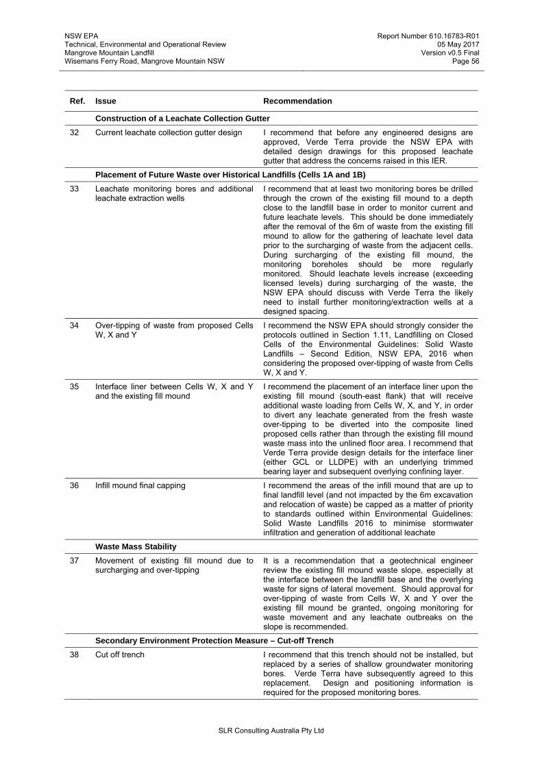
NSW EPA Technical, Environmental and Operational Review Mangrove Mountain Landfill Wisemans Ferry Road, Mangrove Mountain NSW
Report Number 610.16783-R01 05 May 2017
Version v0.5 Final Page 56
SLR Consulting Australia Pty Ltd
Ref. Issue Recommendation
Construction of a Leachate Collection Gutter
32 Current leachate collection gutter design I recommend that before any engineered designs are approved, Verde Terra provide the NSW EPA with detailed design drawings for this proposed leachate gutter that address the concerns raised in this IER.
Placement of Future Waste over Historical Landfills (Cells 1A and 1B)
33 Leachate monitoring bores and additional leachate extraction wells
I recommend that at least two monitoring bores be drilled through the crown of the existing fill mound to a depth close to the landfill base in order to monitor current and future leachate levels. This should be done immediately after the removal of the 6m of waste from the existing fill mound to allow for the gathering of leachate level data prior to the surcharging of waste from the adjacent cells. During surcharging of the existing fill mound, the monitoring boreholes should be more regularly monitored. Should leachate levels increase (exceeding licensed levels) during surcharging of the waste, the NSW EPA should discuss with Verde Terra the likely need to install further monitoring/extraction wells at a designed spacing.
34 Over-tipping of waste from proposed Cells W, X and Y
I recommend the NSW EPA should strongly consider the protocols outlined in Section 1.11, Landfilling on Closed Cells of the Environmental Guidelines: Solid Waste Landfills – Second Edition, NSW EPA, 2016 when considering the proposed over-tipping of waste from Cells W, X and Y.
35 Interface liner between Cells W, X and Y and the existing fill mound
I recommend the placement of an interface liner upon the existing fill mound (south-east flank) that will receive additional waste loading from Cells W, X, and Y, in order to divert any leachate generated from the fresh waste over-tipping to be diverted into the composite lined proposed cells rather than through the existing fill mound waste mass into the unlined floor area. I recommend that Verde Terra provide design details for the interface liner (either GCL or LLDPE) with an underlying trimmed bearing layer and subsequent overlying confining layer.
36 Infill mound final capping I recommend the areas of the infill mound that are up to final landfill level (and not impacted by the 6m excavation and relocation of waste) be capped as a matter of priority to standards outlined within Environmental Guidelines: Solid Waste Landfills 2016 to minimise stormwater infiltration and generation of additional leachate
Waste Mass Stability
37 Movement of existing fill mound due to surcharging and over-tipping
It is a recommendation that a geotechnical engineer review the existing fill mound waste slope, especially at the interface between the landfill base and the overlying waste for signs of lateral movement. Should approval for over-tipping of waste from Cells W, X and Y over the existing fill mound be granted, ongoing monitoring for waste movement and any leachate outbreaks on the slope is recommended.
Secondary Environment Protection Measure – Cut-off Trench
38 Cut off trench I recommend that this trench should not be installed, but replaced by a series of shallow groundwater monitoring bores. Verde Terra have subsequently agreed to this replacement. Design and positioning information is required for the proposed monitoring bores.

NSW EPA Technical, Environmental and Operational Review Mangrove Mountain Landfill Wisemans Ferry Road, Mangrove Mountain NSW
Report Number 610.16783-R01 05 May 2017
Version v0.5 Final Page 57
SLR Consulting Australia Pty Ltd
Ref. Issue Recommendation
Leachate Management
39 Leachate dam access road My recommendation is the design drawings we modified to show access to the proposed dam for leachate tankering.
40 Lack of engineered drawings for proposed leachate dam
I recommend that detailed design drawings are provided for the proposed leachate dam in accordance with Environmental Guidelines: Solid Waste Landfills – Second Edition, NSW EPA, 2016, Impact Assessment Requirements.
41 HELP Model assumptions CES state that the leachate holding pond needs to achieve minimum volume of 6,962 m3 although it is not clear how this figure was derived from the HELP outputs. It is recommended that CES provide details on how they calculated the volume of 6,962 m3 and whether the Area B volume was included, to the NSW EPA for review.
Landfill Capping
42 Landfill capping design No capping design or tie in details into the side wall engineering of Cells W, X, Y and Z or adjacent existing fill mound have been provided by CES. It is recommended that detailed design information be submitted to the NSW EPA for review and analysis
43 Infill mound capping design I recommend a more robust capping system in accordance with Environmental Guidelines: Solid Waste Landfills – Second Edition, NSW EPA, dated April 2016 be adopted that will further reduce stormwater infiltration through the cap, which in turn will reduce leachate generation rates.
Stormwater Assessment
44 Check of input parameters The design parameter C10 runoff coefficient of 0.4 may need further consideration. Whilst this runoff coefficient may be applicable to some areas of the catchment it is likely to underestimate the runoff from the heavily disturbed areas, especially those areas that have been compacted by heavy machinery. Table F3 of The Managing Urban Stormwater: soils and construction publications (Blue Book) is likely to provide a more accurate estimation of the runoff coefficient for peak flows. This should be checked.
The concerns over the C10 runoff coefficient also relate to the design of the dam spillways. It is also not clear what freeboard has been adopted for the spillways (above the 100 year ARI flow level). 300mm is recommended by the International Erosion Control Association (IECA) guidelines. This needs to be clarified by CES.
45 Sizing of sediment dams The design criteria and design parameters used to size the sediment dams are in accordance with the Blue Book. However, it is not clear if the catchment area reporting to the proposed dams to the east includes additional catchment area apart from what is shown in CES SWMP Figure 5 Contributing Catchment for the Sediment Basins. As a minimum (assuming there is no additional upslope clean water runoff reporting to the dams) the catchment area should also include the actual footprint of these dams

NSW EPA Technical, Environmental and Operational Review Mangrove Mountain Landfill Wisemans Ferry Road, Mangrove Mountain NSW
Report Number 610.16783-R01 05 May 2017
Version v0.5 Final Page 58
SLR Consulting Australia Pty Ltd
Ref. Issue Recommendation
46 Design of Sediment Dams The sediment dams are not designed in any detail, with no engineering details provided. It is recommended that these are provided to the NSW EPA for review of adequacy, robustness and review of construction methods and materials in order to assess the compliance with the Environmental Guidelines: Solid Waste Landfills – Second Edition, NSW EPA, 2016 and should to be designed, constructed, operated and maintained in accordance with Managing Urban Stormwater: Soils and Construction Volume 1 (NSW Department of Housing, 2004).
47 Water monitoring program It is recommended that the water monitoring program be updated to include quarterly monitoring of all the dams (not just Sediment Basin 3). It is also recommended that monitoring points be established in the adjacent creek both upstream and downstream of the Licenced Discharge Point in accordance with Environmental Guidelines: Solid Waste Landfills – Second Edition, NSW EPA, 2016, Section 4.3.
Groundwater Review
48 Baseline data There appears to be no baseline data of groundwater quality. A detailed assessment of the hydrogeology for the site is recommended, at the least in the form of a conceptual site model with groundwater contours to show flow paths which in turn help assess potential contaminant source- pathway-receptor risk assessments
49 Monitoring well level data There is no comparison of monitoring well construction details to the proposed landfill cells or depths of receiving waters. Metres AHD is needed in all respects to determine if the wells have been drilled to appropriate depths for leachate monitoring
50 Groundwater-surface water relationship No relationship between surface waters and groundwater appears to have been investigated
51 3D modelled groundwater surface A 3D modelled surface of the groundwater has not been undertaken for the proposal. Without a three-dimensional modelled surface of the groundwater, a detailed risk assessment cannot be undertaken which in turn restricts the determination of the position of environmental monitoring infrastructure. It is recommended that that a three-dimensional groundwater model be undertaken as a priority and submitted to the NSW EPA for review and analysis prior to approval of any detailed design for Cells W, X, Y and Z
52 Re-submitted reports I recommend that the concerns raised in Section 4.2 are addressed within the respective reports and re-submitted to the NSW EPA for review
53 Proposed groundwater monitoring bores Where insufficient water is present within the groundwater monitoring bores, or the monitoring bores are dry, this would indicate that these bores have not been installed to the correct depth within the groundwater, or have silted up and should be redrilled.
54 Groundwater monitoring infrastructure
With the proposed over-tipping of waste from Cells W, X and Y onto the existing fill mound, and the likelihood of increased leachate loading on the unlined Cell 1A (and partially lined Cell 1B), it is recommended that the NSW EPA instruct Verde Terra to install an additional groundwater monitoring well in the far north-west corner of the site on the EPL boundary between 6AS(S&D) and 3AS(S&D).

NSW EPA Technical, Environmental and Operational Review Mangrove Mountain Landfill Wisemans Ferry Road, Mangrove Mountain NSW
Report Number 610.16783-R01 05 May 2017
Version v0.5 Final Page 59
SLR Consulting Australia Pty Ltd
Ref. Issue Recommendation
55 Groundwater sampling & monitoring For the sampling and testing regime to meet the requirements of the Environmental Guidelines: Solid Waste Landfills – Second Edition, NSW EPA, 2016, Section 4.4, Table 5, I recommend to the NSW EPA that the full suite of testing is required of the operator as part of an EPL condition
Proposed Operational Procedures
56 Working face
A working face of typically between 2-3m in height are recommended for safety and more effective compaction. CES has stated in a meeting held in February 2017 between the author, Verde Terra and the NSW EPA that the Filling Plan will be amended to reflect a reduced working face, this needs to be implemented
57 Construction phase plan I recommend that a construction phase plan is produced to clearly show the interaction between landfill operations, ongoing bulk excavation for void creation and engineering of progressive cells etc. An understanding of vehicle movements and proposed access ramps is essential in understanding the proposed site operation.
Maintenance of Leachate Holding Pond Capacity
58 Bunded leachate sludge management infrastructure
Details of any ‘suitably bunded and lined area or tank located in close proximity to the holding pond’ have not been provided as part of the LMP and should be included. The position of the bunded or lined area should be provided to better understand its position in relation to the holding pond. RL’s are required to understand the relationship to the surrounding land to assess any risk of inundation by stormwater flow. My recommendation is that these details be provided to the NSW EPA for consideration prior to approving any further design
Cell W Dewatering
59 Water sampling Prior to any Cell W engineering, any water will need to be removed from the proposed cell footprint. Prior to discharge, sampling will be required under the EPL to determine any degree of contamination (if any) to determine where the water would need pumping to and possible treatment. Sampling of the water column within the cell prior to discharge is recommended as often water quality can decline with depth. Heavy metals and total dissolved solids (TDS) concentrations that exceed standards for discharge to waterways or groundwater must be treated prior to discharge
Temporary Storage, Placement and Stockpiling of VENM
60 Material requirements and testing A detailed technical specification will be required on the materials placed to ensure consistency of materials and compactive effort. An optimum moisture content and maximum dry density would be needed with a target range of compaction limits needed.
61 Materials balance and staging I recommend that a set of materials balance and staging plans are required to ascertain what volumes of fill are required for each stage of development and at what time. During periods of bulk excavation and ongoing operation, locations and volumes of stockpiles are required to understand their impact on the site and environmental considerations. Volumes of materials required for daily cover, progressive capping and rehabilitation and how it impacts the soils balance on site is required.

NSW EPA Technical, Environmental and Operational Review Mangrove Mountain Landfill Wisemans Ferry Road, Mangrove Mountain NSW
Report Number 610.16783-R01 05 May 2017
Version v0.5 Final Page 60
SLR Consulting Australia Pty Ltd
10 CONCLUSIONS
The key objectives of the scope were to advise the EPA and MDA (the Community) on the suitability of the proposed management controls and monitoring framework for the Verde Terra landfill expansion, and of the management controls and compliance with regards to the previous landfill activity, in the context of protecting the environment and the community.
This IER has considered a broad range of information provided by the NSW EPA, CES, MDA and has referred to, where possible, international industry best practice including the 1996 and 2016 versions of the NSW EPA Environmental Guidelines: Solid Waste Landfills.
The 2014 Court Order issued by the NSW Land and Environment Court identifies a range of work for the expansion into the proposed Cells W, X, Y and Z and re-profiling works within the footprint of the existing fill mound. There is no amended Environmental Impact Statement or any Statement of Environmental Effects for the development.
Concept design drawings and associated technical documents, together with operational management plans provided by CES have been submitted to the NSW EPA and are currently under review. The purpose of the CES documentation is to provide a broad overview of proposed cell layout and construction, to outline proposed engineering containment barriers, leachate management infrastructure etc and present more detailed information on landfill operational procedures. Detailed designs for each individual landfill cell and its connection to the existing fill mound are required to be submitted to the NSW EPA prior to cell construction, as is normal process.
The Mangrove Mountain landfill can be broadly described as having two main aspects, the existing fill mound, comprising Cells 1A and 1B, and the proposed expansion into Cells W, X, Y and Z.
The existing fill mound sits within a sensitive area (in or within 40 metres of a permanent or intermittent water body or in an area overlying an aquifer that contains drinking water quality groundwater that is vulnerable to pollution) as defined by Environmental Guidelines: Solid Waste Landfills – Second Edition, NSW EPA, 2016.
With regard to the existing fill mound, based on the evidence reviewed, there appears to be little, if any engineered barrier within the base and side walls on Cell 1A constructed prior to 2009. CES has stated that the base of Cell 1A, especially towards the south-west has been graded to allow basal leachate to fall to the south-eastern edge of the cell, whereby it will be managed within a collection trench which will convey the leachate to the proposed Cells W, X and Y.
Although the base of Cell 1A within the existing fill mound appears to be without an engineered barrier, data provided by CES states that the local Hawkesbury Sandstone shows an average hydraulic conductivity to be low with results in the order of 1x10⁻⁶ m/s for the shallow and deep nested wells. These data indicate that the permeability of the underlying Hawkesbury Sandstone is lower than might be expected for a medium to coarse grained sandstone. A certain degree of additional impermeability will likely be afforded to the sandstone surface by biological clogging and silt/fines deposition derived from the emplaced waste mass and leachate.
Cell 1B, from the evidence reviewed appears to have a modern composite lined engineered barrier comprising a GCL and overlying HDPE geomembrane. It does appear however, that currently the south-western and north-eastern ends of Cell 1B have not been afforded the same degree of engineered barrier, and remain unlined.
A review of the available quarterly surface water and groundwater monitoring data does not appear to show any evidence of impact from the landfill. The extent and operational functioning of the current monitoring network however needs improvement together with a more thorough understanding of the local groundwater depths and flow directions derived from a 3D groundwater model.

NSW EPA Technical, Environmental and Operational Review Mangrove Mountain Landfill Wisemans Ferry Road, Mangrove Mountain NSW
Report Number 610.16783-R01 05 May 2017
Version v0.5 Final Page 61
SLR Consulting Australia Pty Ltd
To minimise the environmental impacts of overtipping onto the existing fill mound from the proposed Cells W, X and Y, I have recommended that an interface liner (either GCL or LLDPE) be installed upon the existing fill mound waste flank facing the proposed new cells and at least two monitoring bores be drilled through the crown of the existing fill mound to a depth close to the landfill base in order to monitor current and future leachate levels. Areas of the existing fill mound not impacted by the 6m excavation and relocation of waste should be capped as a matter of priority to minimise stormwater infiltration and generation of additional leachate.
In terms of the proposed Cells W, X, Y and Z, detailed designs with supporting materials design and suitability information is required for submission to the NSW EPA. The groundwater assessment undertaken for the existing fill mound should be extended to cover the area within the proposed cells to determine whether any or all of the proposed cell bases sit beneath the groundwater level.
In respect of the POEO Act, specifically clauses b, c, d, f1 and i, and how the site meets these requirements, I have reviewed a significant catalogue of documentary information and photographs enabling me to draw conclusions and make forward recommendations. This IER has made a number of recommendations throughout on practical measures to prevent, control and mitigate pollution that where implemented, would ensure that the landfill's design meets best practice, and that risks from ongoing development of Cells W, X, Y and Z together with the existing fill mound will be minimised. This IER has concluded that significant improvement is required in order to comply with necessary operational and regulatory procedures and policies. Furthermore, due to the sensitive nature of the site being in an area overlying an aquifer that contains drinking water quality groundwater, the development needs additional regulatory scrutiny.
The decision on how the current CES documents (and any subsequent amendments undertaken based on the recommendations within this IER) relate to the original 1998 Development Consent (and EIS), in my opinion rests with the NSW EPA and the current Central Coast Council.
Many of the recommendations raised in this IER regarding the landfill expansion into Cells W, X, Y and Z may be overcome with a greater level of detail in the design in line with the Environmental Guidelines: Solid Waste Landfills – Second Edition, NSW EPA, 2016, independent robust CQA supervision, groundwater modelling etc.
The existing fill mound sits currently in abeyance, with an un-profiled surface, temporary waste capping placed, little vegetation and without the benefit of a final stormwater management network, all presenting a possible pollution risk if allowed to continue. The proposed Cell W currently collects stormwater runoff and needs continued operational management. The risk of pollution will be mitigated with an agreement on the proposed detailed designs (in line with best practice guidelines), and operator commitments towards robust CQA.
It is important to ensure that previous operational activities that may lead to potential environmental risks are not continued into future operation of the site. Operational practices need to be improved, and be in accordance with the conditions of an EPL and approved LEMP. Stronger and more thorough regulatory oversight from the NSW EPA and Council is also required to achieve necessary performance outcomes into the future.

BRISBANE
Level 2, 15 Astor Terrace
Spring Hill QLD 4000
Australia
T: +61 7 3858 4800
F: +61 7 3858 4801
CANBERRA
Suite 3 Level 4, 11 London Circuit
Canberra ACT 2600
Australia
T: +61 2 6287 0800
F: +61 2 6287 0801
DARWIN
5 Foelsche Street
Darwin NT 0800
Australia
T: +61 8 8998 0100
F: +61 2 9427 8200
MACKAY
21 River Street
Mackay QLD 4740
Australia
T: +61 7 3181 3300
MELBOURNE
Suite 2, 2 Domville Avenue
Hawthorn VIC 3122
Australia
T: +61 3 9249 9400
F: +61 3 9249 9499
NEWCASTLE
10 Kings Road
New Lambton NSW 2305
Australia
T: +61 2 4037 3200
F: +61 2 4037 3201
PERTH
589 Hay Street
Jolimont WA 6014
Australia
T: +61 8 9422 5900
F: +61 8 9422 5901
ROCKHAMPTON
M: +61 407 810 417
SYDNEY
2 Lincoln Street
Lane Cove NSW 2066
Australia
T: +61 2 9427 8100
F: +61 2 9427 8200
TAMWORTH
PO Box 11034
Tamworth NSW 2340
Australia
M: +61 408 474 248
F: +61 2 9427 8200
TOWNSVILLE
Level 1, 514 Sturt Street
Townsville QLD 4810
Australia
T: +61 7 4722 8000
F: +61 7 4722 8001
AUCKLAND
68 Beach Road
Auckland 1010
New Zealand
T: +64 27 441 7849
NELSON
5 Duncan Street
Port Nelson 7010
New Zealand
T: +64 274 898 628
NEW PLYMOUTH
Level 2, 10 Devon Street East
New Plymouth 4310
New Zealand
T: +64 0800 757 695
SINGAPORE
1 Fullerton Road
#02-01 One Fullerton
Singapore 049213
T: +65 6735 7972