
TECHNICAL - dtic.mil · or Elliptical Heads .. ..... . 15 Theoretical ... Inter.tagc Safety Factor...
49
TECHNICAL MEMORANDUMk/ •(V A DESIGN CRITERiA AND ANALYSES FOR THIN-WALLED PRESSURIZED VESSELS AND INTERSTAGE STRUCTURES tMf L )-11)623 26 JUNE 1959 Best Available Copy Namc" EtCROFICHEsK MISSILES and SPACE DVISION LOCK•gKC At *CUAVYt CORPORATION dU ft1VVAL6t. CALI P "i"Pmr mm.-
Transcript of TECHNICAL - dtic.mil · or Elliptical Heads .. ..... . 15 Theoretical ... Inter.tagc Safety Factor...

TECHNICAL MEMORANDUMk/
•(V
A DESIGN CRITERiA AND ANALYSES
FOR THIN-WALLED PRESSURIZED VESSELS
AND INTERSTAGE STRUCTURES
tMf L )-11)623 26 JUNE 1959
Best Available Copy Namc"
EtCROFICHEsK
MISSILES and SPACE DVISION
LOCK•gKC At *CUAVYt CORPORATION dU ft1VVAL6t. CALI P
"i"Pmr mm.-

11.IS D - 162•
FOREWORD
Th*.s. r.,-;ort, basei on a review of the various .,hilos.phies
of iesign c-riteria currently used in the missiles and
spcaecraft industry, prestnte an approach for preliminary-
le<gn analysis of thin-walled pressurized vessels and
interstage structures. It iL intended primarily as an aid
toward more rapid and consistent estimations of structural
gages and weights.
Although the report emphasizes preliminary design usage,
the material presented Is not limited to prelimin'..ry design
analysis.
Examples are included of use of the equations and graphs
presented.
ACKNOWLEDGMENT
ThMe author wishes to express his appreciation to R.L. Harriiit,
L.L. Long,and M.L. Vaughn for helpful information which they
contributed to this report.
li
LMSD- 1.! 162.
TABLE OF CONTENTS
S•. " t onPage
FOREWORD ........ ................... . . . . . . . . ii
LIST OF ILLUSTRATIONS AND TABLES .... .............. .... iv
NO:*ENCLAT'9RE ................ ....................... v
SU.ARY ..... ................................... .. viii
INTRODUCTION ............ ........................ .!..
THIN-WALLED PRESSURIZED STRUCTURES ..... .............
Classification. . . . ...... . . . . . . . .
Safety Facto.*s Criteria and Allowables . ........... 3
STRUCTURAL ANALYSIS METHODS .................... 6
General . ........................... 6
Elliptical and Spherical Ends . . . . . ... .... . 6
Cylindrical Shelli ............. * . . . .. .. 11
Conical Shell ............... .................... .... 12
RelationshIp of Volume and Diameter as a Func, ion o,Fineness RPtio, L/d ............. ................. . . 15
Spherical Tanks vo Cylindrical Tanks with Sphericalor Elliptical Heads .. ................ . 15
Theoretical vs Actual Weights ..... ............. .... 21
TANKS AND :NTERSTAGE STRUCTURAL WEIGHT INTERRELATIONSHIP. 22
CYLINDRICA' AND CONICAL INTERSTAGES UNDER AXIAL LOADING . .
Cylindric. Sections............ . . . . . . . . . . . 2'
Conical S, tions. . . #. . .. . . . . . .. . . . . . . . . .* 2j
Inter.tagc Safety Factor Criteria and Buckling Allowables.. 28
REFERENCE....................................... .. .... 33
EXAMPLES . ....... ................ 34
Appendix ;, . ......... '
Appendix B. .......... . . . . . . ........
Appendix C .............. .......................
iii
FEMSD-311623F
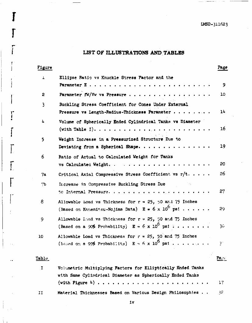
LIST OF ILLUSTRATIONS AND TABLES
Figure Page
I Ellipse Ratio vs Knuckle Stress Factor and the
Parameter E . . . . . . . . . . . . . . . . . . . . . . . . . 9
2 Parameter fW/Vw vsP re u................. 10
3 Buckling Stress Coefficient for Cones Under External
r Pressure vs Length-Radius-Thickness Parameter .1...... I4
"4 Volume of Spherically Ended Cylindrical Tanks vs Diameterf (with Table I). . . . . . . .. . . .. . .. .. . . 16
5 Weight Increase in a Pressurized Structure Due to
"Deviating from a Spherical Shape.... ........... 19
6 Ratio of Actual to Calculated Weight for TanksF vs Calculated Weight ................. 20
7a Critical Axial Compressive Steess Coefficient vs r/t. . . .. 26
F b Ir.crease In Compressive Buckling Stress Due
tc Internal Pressure. . . . . . . . ..... 27
8 Allowable Load vs Thickness for r = 25, 50 and 75 Inches
(Based on Kanemitsu-Nojima Data) E = 6 x 10⁶ PSI ..... 29
9 Allowable Lc-,,ad vs Thickness for r = 25, 50 avd 75 Inches
(Based on a 90% Probability) E =- 6 x 10⁶ ps 36
10 Allowable Load vs Thickness for r - 25, 50 and 75 Inches
(•i.;ed on a 90% Probability) E 6 x 10⁶ pal...... .
Table Pa,,
I Volumetric Multiplying Factors for Elliptically Ended Tanks
with Same Cylindrical Diameter as Spherically Ended Tanks
,with Figure 4) 17
II Material Thicknesses Based on Various Design Philosophies .2
iv

E248D-31l623
NOMENCLATURE
"mamjt(,r ell iptical radius, cylindrical radius
b minor elliptical radius
c refers to combined stresses
C critical axial compressive stress coefficient - r r
C buckling stress coefficient for conesP
CA buckling stress coefficient for cones
Pcr req /Eq 3 ( 0.904Cp for P- 0.3)
4 diameter
dc diameter of cylinder - 2a
d diameter of sphere
e elliptical eccentricity = [1 - (1/k2)]1/2
E parameter= 12k + 1/(k2- 1)1/2 in Ik + (k2 J)1/2]/[k (k2 1)1/2]
E Young's modulus
f stress
fc stress in cylindrical portion
fh stress in head
fs stress in spherical portion
F yield point allowable of materIal corresponding to 0.2% offsetY on stress-strain diagram
k ellipse ratio - a/b
K stress factor for a particular ellipse ratio, k
Ic length of cylindrical portion
A4.e length C¢f cylinder corresponding to minor radius
Ain length of cylindrical portion of interstage structure
V

LMSD-31162 3
L overall length (= I + 2 x minor radius of head for propellant tank)C
L length of generatrix of cone or of conical frustrum•
L length of equivalent cylinder = (0.7)rI + l.45r 2 ) L/2.2r,,eq 2
M refers to membrane Atress only
p working pressure
P critical loader
r critical preszure•cr
r raýius of cylinder
r radius of cone at base perpendicular to generatrix = r/cos Cteq
rI1 m.4nor radius of truncated cone
Sbase radius of cone (r2 > r,)
crown radius = Ka
t tý,Ickness of cylindrical shell
t tlicKnes of crowncr
t eqaivalent thickness = (tI + t )/2hi cr
t. gaý-Te of interstage structure
t. thickness of knuckle
t th.Ickness of spherical head
t spnerical head gage determined on basis of membrane stresses only
V vo iume
w density of material
"Win density of interstage structure
vi

LMSD- 311623
W weight
W h weight of nead plus cylindrical shell
W weight of spherical tank
AW weight gain
G
9 ccne half angle
D'Lasticity coefficient
Poisson's ratio
a critical axial compressive stresscr
increase in critical axial compressive stresscr
vii

SUMMARY
1nl.s report considers the problem of varied philosophies of design criteria in
tht missilcs and spacecrift industry in relation to preliminary design work.
Ti.,. rep;ort uffers a set of design ground-rules consistent with safety factors
anj •Lauteriuls allowable as an effective approach not only for structural pre-
liminary design but also for general application by the structural design
analyst.
Specific uses involving design of thin-walled pressurized vessels and inter-stage structures are presented. Criteria with respect to factors of safety
and use of buckling probability curves are in2luded for structures in which a
buckli.ng type of failure under axial compression predominates.
Formulae for determining gages for tanks and interstages are given and a set
of graphs is provided which permits rapid calculation of the weights of tanks.
The report also contains a graph which shows the weight penalty incurred for
tanks which deviate from a spherical shape, and there is a graph presenting the
volume of a tank as a function of the diameter.
Critical axial compressive stress coefficients for different philoscphies of
structural design are graphically .ilustrated and curves for allowable load
versus thickness based on these ph>losophies are preaented.
viii

Section 1INTRODUCTION
A urvey r;' ssisie-ano.-spacecra.t design practices has demonstrated the need
'o establish consistent design criteria for thin-walled pressurized veeseis
and interstage structures. Up to the present, attempts to achieve consistency
of results from the various design criteria in uce in industry have been some-
wnat obscured by efforts to correlate experimental results with the variousý-trength theories. The two theories used most widely for establishing the
tiictcness.s of the walls of pressurized structures of isotrcpic material are
a. folIow-i:
"o Maxiy:;um Stress Theory, f = f (subscript y refers to yield)yThis theory assumes that failure is not influenced by the
presence of one stress acting at right angles to the other.
"* Distortion Energy Theory or Shear Energy Theory for Two-
Dimen~sionial Stress, f .,. f22 - f f f
This theory is based on Hooke's Law and, consequently,
requ.ilres use of the yield stress. Furthero this theoryassumes that the material has the same yield point in
tension and in compression.
The thickness of the walls based on equations of the maximum stress theory isabout 15 percent greater than the thickness obtained from equations of the
distortion energy theory. However, the maximum stress theory is more generallyused. One reason is that this theory is easier to use. Also, since it is moreconservative, it is more appropriate for use for pressure vessels which aresubject to premature failures due to mismatched welds, or to failure caused by
some other stress concentration.
1

LMSD-31l623
Auother design area where there is a great deal of inconsistency is that of
mcnocoque structures under axial compression. Here, large discrepancies
between theory ard experimental resuits are well documented Recent attempts
t- deal with these differences have been made using failure-probability theory
coui.ed with vqrious factors of safety.
Design criterit and methods of analyses leading to consistent results in pre-
"2intinarV design applications are presented in the following pages.
2

LMOD-311623
Section 2
THIN-WALLED PRESSURIZED STRUCTURES
2.1 CIASSIFICATION,
Structures loaded by internal pressurization are classified generally ir. the
missile and spacecraft industry as follows:
2.1.1 Propellant Tanks
Ordinarily, ;ropellant tanks form an integral part of the basic primary struc-
ture, constitute a fairly large percentage of the total structural weight,
and are moderately to highly pressurized.
2.1.2 Pressure Vessels
Generally, pressure vessels are removable, experience a great many more cycles
of pressurization than do propellant tanks, and are highly pressurized.
2.2 SAFETY_ FACTORS CRITERIA AND ALLOWABLES
For missile and spacecraft applications each company has its own value for a
safety factor. This is also true for the military services and for civilian
governmental agencies. (See Appendixes A and B which show the results of a
recent survey together with present LMSD policy.)
3

LMSj-31162 ý
It is seen clearly from the Appendixes that any factor selected will have its
adherents and its detractors.
2 1 Safety Factors
For thin-walled pressurized structures the fcllowlng safety factors are recom-
mended for preliminary design work. It should be noted that the ratio of ulti-
mate to yield of the material may in some cases warrant a re-evaluation of these
factors.
Propellant tanks
"* That are non-hazardous to personnel or vital equipment 1 00
"* That provide a special precautionary safety measure
for personnel 1 i0
"* That are hazardous to personnel or vital equipment 1,33
Pressure vessels
"* In remotely-launched missiles 100
"* In aircraft and vehicle-launched missiles 1.33
The pressure considered in the above applications is the working pressure,
defined as tbh maximum pressure to which the component is subjected under steady
state conditions or the effect of launch or catapult loads, whichever is the
more severe.
* For example, for the booster for a manned capsule which has an ejectiondevice with an exceptionally high degree of reliability.
4

LMSD--3 l625
2.2.2 Material Allowable
-separable from safety factor is the material allowable which is generally
based on uniaxial-stress data. Admidttedly the use of any material allowable
based orn uniaxial-test data Is en oversimpllficaton for multiaxial-stress
systems such as pressurized tanks. The strain hardening ch'rracteristic,
which is a- Important factor, the heat-treat cjcle, and the shape of the
vessel influence the maximum pressure a vessel can withstand. Depending on
the value of the strain hardening parameter, for example, the burst stress
as a function of the ultimate uniaxial tension stress can vary approximately
p3us-or-minus 15 percent. Ductile materials in the arunealed state have burs4-
stresses which vary between 90 percent to 105 percent while cold-rolled
metals range between 100 and 110 percent of the maximum. These variations in
values are based on information contained in Reference 1. (See, also Ref-
erences 2 and 3, two recent papers wh'ich include, among other topics, further
discussion of the effects of strain hardening.)
A fairly reliable and acceptable allowable for preliminary design is the
vield point (0.2 percent offset) of the material fcr tbe minimum expectea
strength k"A" values of ANC-5/MIL-HDBK-5) in combination with whatever
special factors are required for welds, or other stress risers. A weld
efficiercy of 85 to 90 percent is a reasonsble value. If considered desir-
able, built-up lands at the welds can be used wi#h little weight penalt.y'
5

Section 3
STRUCTURAL ANALYSIS METHODS
1 GENERAL
At a sufficient distance from the juncture of the ends with the cylindricFl or
conical shell (where interaction does not occur), the maximum stress in the
shell due to internal pressure generally is determined on the basis of the
simple hoop-menbrane stress formula.
For preliminary design purposes the gages and weights of the cylindrical or
conical shell will be determined using the simpl2e hoop-membrane formula. Th,
wcl-ghts of the heads (or ends) will be determined using an equivalent thicknnsu
of the knuckle-crown arrived at by accounting for the superposition of membrane,
discontinuity, and local bending stresses. Elliptical and spherical heads only
are compared. It should be noted that the spherical-head equations are specili
cases of the elliptical.
Examples of the use of the following equations and graphs are included at the
end of this report.
3.2 ELLIPTICAL AND SPHERICAL ENDS
By assuming an equivalent head-thickness which is an averaSe value of the
knuckle-and-crowr thickness a fairly close weight value is obtainable for
elliptical ends. (Reference 4.) For completeness, some of the more general
equations of the referenced article are included here.
6

LMSD-311623
3.2.1 Equivalent Head-Thickness for ElliptIcal Ends
The equivalent head-thickness is determined as follows:
(a) Knuckle thickness, tk
S= Kp,,/f ( )
where f = stress
K = stress factor for a particular ellipse ratio, k = a/b.
(An envelope curve 1tr K vs k for combined membrane,
discontinuity, and local bending was obtained from
Reference 5.)
a = major elliptical radius (or cylindrical radius)
b = minor elliptical radius
p = pressure
(b) Crown thickness, t cr
tcr = pR/2f (2)
where R = crown radius = ka
(c) Equivalent thickness, te
te= (t + t r2 = pa(K + k/2)2f (3)
3.2.2 Elliptical (oblate spheroid) Weight and Volume
(a) Surrace area of an ellipsoid is:
where e = eccentricity = (1 - 1/k2)•l/2
7

I2SD-311623
If (b) Ellipsoidal head weight is:
W - (*ta vp/2fk)(K + k/2){12k + In~k I. i~/ k -(k2 1)/.
M ,wa3E/2k (K + k/2) wp/f = *a2 Wte/k (5)1-
where w - density of material and
V" E is the term in the large bracketsI
E 2k + O/k 2 _ 1)l1/2 1nk+ 1)1/2~ (6)
I E is plotted in curve of Figure 1. (Note: Reference 4
is in error for k > 2.5)
For just one head the weight is, of course, just 1/2 W.
1o(c) Volume of ellipsoid is:
I V 4/3 a2 b = 4/3 3 /k (7)
(d) Weight/Volume
W/V n 3E/8 (K + k/2) wp/f = 3Ewtl/4a (8)
SThis relationship is the basis for Figure 2.
Ii_
L8

120 . -
~- ~A(COMBINED STRESS)
41.7t0ENVELOPE CURVE
COMBINED STRESS
CURVE FOR K !-OR7-MEMBRANE STRESS
0.80
w5 0.70
4 0.50WDO 1.25 1.50 1.75 2.00
ELI. PSE RATIO*NOTE: FOR SPHERICAL TANKS USE Km 0.50 AT km 1.0
FOR SPHERICAL HEADS USE Km 0,6? AT It a 1.0
FI gwire I Ellipse Ratio vs Knuckle Stress Factor and theParameter E
9

LM4SD-31l623
700
SPHERICAL HEAD
SPHERICAL TANKS
500
II
DV!DING BY COS
4STRESS, PSI
T H- -f-- -- VVOLUME, CU. IN.
I ~w= CENSITY, LBS/cum.IN
0
0 100 200 300 400 500
Figure 2 Parameter N/lvw vs Pressure
10
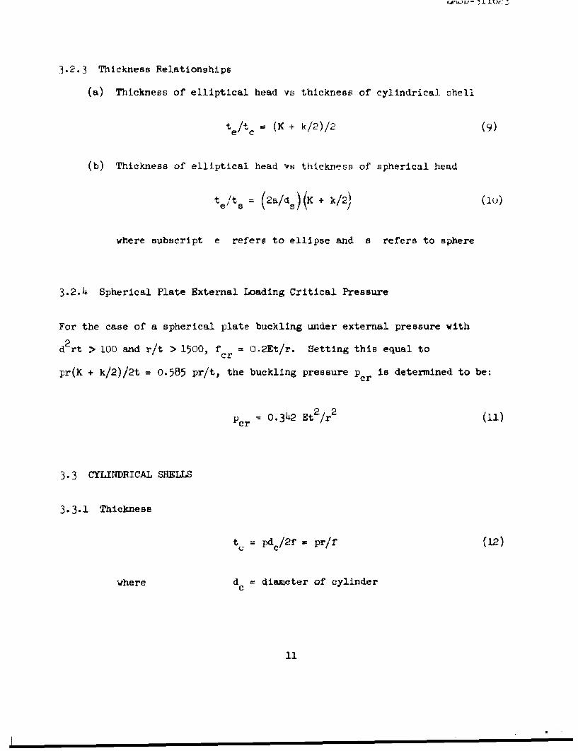
3.2.3 Thickness Relationships
(a) Thickness of elliptical head vs thickness of cylindrical shell
teltc = (K + k/2)/2 (9)
(b) Thickness of elliptical head vs thickness of spherical head
te/ts = (2a/ds)(K + k/2) (iu)
where subscript e refers to ellipse and a refers to sphere
3.2.4 Spherical Plate External Loading Critical Pressure
For the case of a spherical plate buckling under external pressure with
d 2rt > 1O0 and r/t > 1500, f = O.2Et/r. Setting this equal tocr
pr(K + k/2)/2t = 0.585 pr/t, the buckling pressure per is determined to be:
cr 0. 342 Et 2 /r 2 (11)
3.3 CYLINDRICAL SHELLS
3-3.1 Thickness
t = pdc/2f = pr/f'j (L2)
where d = diameter of cylinderC
11
LMSD-311623
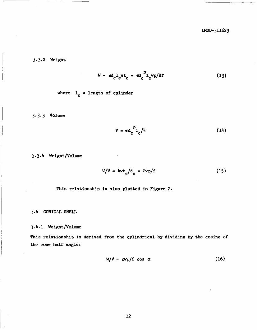
J. 3.2 Weight
W - wdclwtc 0 idc2 1ewp/2f (13)
where 1c Length of cylinder
3.3.3 Volume
V=d c2lc/4 (14)
3.3.4 Weight/Volume
w/v - 4wtc/d " 2p/f (15)
This relationship Is also plotted in Figure 2.
s.4 CONICAJL SHELL
3.4.1 Weight/Volume
This relationship is derived from the cylindrical by dividing by the cosine of
the cone half angle:
W/V 2wp/f cos a (16)
12

U4SD- 3116,-3
*,.h.4 External Loading Critical Pressure
The critieal ,re•;:ure that will buckl,! i conical section under extcrnai loading
cat. b. determined fromn
2n Et 3
P r = C 1) 1 (17a)"12(1 - r) q eq
eq eq eq,= C a E / (ý/r e~ F(Tb)
for ji (Poisson's ratio) a constant
'a.
where L as a function of r's and L is taken aseq
0.75 r1 + 1.45 r 2 L"eq 2.2r 2
A 90 ercent probability curv,- of L0 /r t vs C forI - 0.3 ib plotted Ineq eq •
Filhu-,: 3. The information for determining this curve was obtained from
He: P.rince 6.
13

U -H
4-)
P4)4
14)

LMS2D-311623
3.5 RELATIONSHIP OF VOLUME AND DIAMETER AS A FUNCTION OF FINENESS RATIO, L/d
It can be shown that
f( 3L/d - 1/k (19)
where L is the overall length. Figure 4 depicts this relationihip
graphically for spherically ended tanks. Table 1 which accompanies
this figure gives volumetric multiplying factors for determining the
volume of elliptically ended tanks with the same cylindrical diameter
as the spherically ened tanks.
3.6 SP!ERICAL TANKS VS CYLINDRICAL TANKS WITH SPHERICAL OR ELLIPTICAL HEADS
Weight relationship as a function of fineness ratio, L/d is determined to be:
Whe 33/8 LK + k/2 ) p + lpf ffd 1 /L, 3k]•! +.- . . (2wp/f(9 4,3/2 (K + k/2) wpl/ (rsS/6)
(K4 k/2)WP/fh* + (d 2 1)(W/f)(20)
d sa3/2 (K + k/2) (wp/f) (0
where Whe = weight of heed plus cylindrical shell
W = weight of spherical tank
15

LMSD-311623
8
> -M P 0
Ion
°d0
~~> 4u ,I ,,,| I._ _,_ _ _ _ _ _ § )
0 III0
000
0
161

t*D- 311623
TAEIZ I
SAC CYLINDRICAL DIANMTR AS ICALLY ENDED TANIS(wrw 7IUTZ Ii)
L k wlt•ply sphericallyI Icd.lk Volums by
1.25 1.04100
2 1.50 1.o667
1.75 1.0857
1.25 1.02o5
3 1..50 1.0117
1.75 1.o536
I.25 1.0182
S1.50 1.0303
1.75 1.0390
1. 25 1.0143
5 1.50 1.0238
1.75 i.o3o6
1.25 1.0100
7 1.50 1 .0167
1.75 1.0214
17

[
A simplification is obtained by assuming for the head and cylinder and sphere
the same allowable stress, F anL'. the same material
2
Whc d 2 E/2k + 4dclc/(K + k/2)
Ws 2d 53/dC(K + k/2)
Now for equal volumes of sphere vs head plus cylinderFWd 0 3 4/3 Wa 3/k + jrd. 1 /4 (22a)-r- M c
d63= djc /k + 3/2 d c2 1c = d c(dc2 /k + 3/2 dclc)(22b)
F Finally equation (20) reduces to
-Whc Edc 2 /4k + 2dclc/(K + k/2)
K + k/2
E/iik + 21 c/d,,(1/K + k/2) (3l /k + (3/2 le/d 0)/(K + (23)
Figure 5 based on equation (23) shos the weight penalty due to using other
than a spherical tank. The lower curve of each set is for the membrane while
the upper is for combined stresses. In Reference 7, Figure 6.2 also shows the
curve for the spherical tank where membrane stresses only were considered. The
tick mark on each of the curves indicates the L/d value at which the diameter
of a tank with a cylindrical body and elliptical heads is the same as the
18

LL4SD-3uJ623
2.4
2.754
2.2a
a 2.0
1C L
-J
1.91wC
I- N.-- i-
1.5 8.345Y TT
dC
1.62re5 WegtIreeinaPeuied trtueD oM"itn rcna8hrla hp
.j9

I.00r 0
_ _ _ _ _ _ _ _ _ _ _ re-I
4 id
0 0
4.)
8 0t~ Z 0
imoilmlyni-U 4 20

diameter of a spherical tank of equal volume. For comparative values of
cylindrical bodies with spherical heads vs elliptical heads at other L/d
values merely add the difference between the chosen value and L/d - 1;
e.g., a spherically-headed tank of L/d of 1.5 has the same diameter and
volume as an elliptically-ended tank with k 1.25 when the latter has at.
L/d of .993 + .5 = 1.433. To the left of the tick marks an equally-volumed
elliptical tank has a larger diameter, to the right a smaller.
3.4 THEORETICAL VS ACMMAL WEIGHTS
The values obtained from the graphs and equations presented are theoretI-al.
I t should be noted t~herefore that. where structural reinforcements are rtrqiri-d
because of dcors struceural-sipport fittings, or baffi*s, affecti-- 'he sres3
distributio-, the ai-tual v0ghts will be greater. For small tanks this increase
may be In the r~eighborhood of 50 percent whereas for large tanks the aerua.
weight. may be aboujt 15 percent greater. Figure 6 shows this relationshlp.
The curve Is based or. an evaluation of the weigh.ts of a few 1,quid-prope'l at
tanks. However, it Is thought to be indicative of what :,a- be exp-! .d fir
all tanks. Whet. more comprehensive data becomes available lhis r 4 •.wur wvi
be revised.
21

FU4SD- i11623
Section 4TANKS AND INTERSTAGE STRUCTURAL WEIGHT INTERRELATIONSHIP
From Figures 2 and i it Is obvious that a spherical tank alone is the lightest
,-ri,, - t well known fact. Also, a cylindrical tank with spherical ht.ad:, 1!•- It I|,lt~.r 1i ;ien thran a cylindrical tank with elliptical heads. However, th"
I w#-i#ht. of' an ,:llipticnlly ended tank when coupled with the shorter length ofain Irit.r:tage structure may be lighter than a comparable combination of a
I :;,hferlca• .y trnded tank aind an Interstage structure.
A breakýr-.c'ven tyickri,;:; b't. be .J-terlnii ied as follows (consz,|crittti o-t,- o ttoiz
,'fW U tnnk):
FF)r equal diarnete•-m from Eq. (2,2b) the length, AIV& of the cylluirlcal so-Oloil[ ,I' th- ei11prse-,.ylln,1Ier nombination for equal volut,,w with 1 sphilie io
I.
C.=i/;( -1k.21( - i/k)
From Eqs. (5), (13), and (24) the weight penalty chargeable to the us- iA at.
,11]Ipsoiudl hend is determinfed as the diffcere-nce betw<.c'n the w(ig-Iht of thl,
22
ellipsoidal head and the differential length of the cylindrical portioD as
compared to the weight of the spherical head, i.e.,
,w p= , l.E/32k (K + k/2)vp/fl + ird3/6 (1 - l/k)vp/f. - 013/8 (K + k/2)vp/fi (25)
Fur copal stresses with K for the spherical head - 0.67, therefore,
&wp M Ip/f uI3/8 [(K + k/2)9i4k + 4/3 (1 - i/k) - 1-171 (26)
where subscript p refers to penalty.
The weight gain due to the shorter interstage on the elliptical head as compared
to the spherical head is obtained as follows:
For equal diameters the differential length, Alcin is
�[Id4
Icin (d/2 - d/2k d/2 (1 - 1/k) (27()
where subscript in refers to interstage
23

Weight gain a M " 2wwin d/2 tin (d/2 - d/2k)
where subscript G refers to gain
A W G win d2 /2 tin (1 - L/k) (28)
The interstage gage to equalize weighta is determined by equating (26) to (28)
in + [4 (1 - i/k) 1.17]i~n wne 41- - 1 ( 7
c[ 0. 1.W in (k - .16:--1
(29)wt - + k12("•])-•I 1.33, + 0.16, -k,•--T
= in 1. 6 06 (k -k ) 17
v~te [1i?-33T + + 0.16 ( k-l(~/-in te 17 (k - 1)(K + k/2) (k-1+K--TT
where tin = interstage thickness
t = spherical head thickness based on membrane stress onlym
The necessity for using a larger gage than that obtained from Eq. (29) indicates
that, with respect to weight, it is more economical to go to an elliptical head.
24

Section 5CYLINDRICAL AND CONICAL INTERSTAGES, UNDER AXIAL LOADING
Equation (29) determines the trade-off thickness for interstage structure -
Ic AWiti, the propellant tank re4uire:,ments.
5 1 CYLINDRICAL SECTIONS
In ballistic missile applications the primary loading condition is axial
compressiorn for which the design allowable for thin-skinned monocoque :t.• re'
Is basea on buckling criteria.
Un .resourized buciing curves for cylinders witli two different valuc6 oi'
probability are plott!d in Figure 7a, with the Kanemitsu-Noji:%a curve an-
Gerard's curve included for comparison. Figure 7b indicates the effect of
pressurization. (The dashea line for 99 percent probability is an approxi-
mation.) Note that the total critical external load that can te supported
is the sum of the Pcr for p = 0 plus the Pcr for p > 0 plus the pretension
a.~ i., P 2 ,r•t 2 (C +•c) + •rr •crtotal
5 2 CONICAL SECTIONS
Fur conical interstage structure an approximation of the critical bu,:klJii
loa•d can be obtained by multiplying the cylindrical buckli.:J * ca: by C- (7

LMSD-3i1623
100
0.80
0.60 GERA•RD KANEMI SU NOJIMA
040
90%
-0.20
ý% 0.06_8
U.04
0.02
40 60 100 200 400 600 1000 2000 4000
t
Figure 7a Critical Axial Compressive Stress Coefficient vs r/t
26

1SD-311642
1-- -0-
8
00
0 U)Q,)
-; 0
d
27•
I~ t ,',, -- i
€o 0 oS30J

rLMSD-311623
5.3 INTERSTAGE SAFETY FACTOR CRITERIA AND BUCKLING ALLOWABLES
A tabulation of safety-factor criteria and allowables used in industry for
missile applications is shown as Appendix C.
5.3.1 Kanemitsu.Nojima, and 90 and 59 Percent Failure Probability Curves
A 1.25 factor of safety applied to limit to obtain ultimate has been used with
allowables determined from the 90 percent failure probability curves. Another
approach has been to use a 1.00 factor of safety in conjunction with a 99 per-
cent failure probability curve. Present practice for manned aircraft is to
use a 1.50 factor of safety coupled with the Kanemitsu-Nojima curves.
Figures 8, 9,and 10 show the Kanemitsu-Nojima buckling curve and the 90 and
99 percent failure probability curves.
Table II shows a comparison of the gages obtained from the different design
philosophies employed. Arbitrary values were used for loads. The r/t value-
and the L/r values are generally within the range of interest of present
ballistic missile applications. It can be seen from these curves and the
tabulation that a factor of safety of 1.00 in conjunction with 90 percent
robability 13, for the range of interest which concerns us here, as con-
orv-tive as pilotea aircraft ,hilosophy holding, to a 1.5) factor of ;.afety.*
.3.2 Recommended Values for Safety Factor and Probability Allowable
For p.reliminary design purposes the following values are employed for structures
subject to a buckling type of' failure:
Application Factor Probability
Non-hazardous to personnel or vital equipment 1.00 90%
Special precautionary safety of personnel 1.00 90%
Hazardous to personnel or vital equipment 1.10 90%
* This assumes, of course, a rigorous "loads" correlation.
28

I2MD-311623
44
2 w~w 1K zi
t(44
22
104

LMISD-311623
IT.¶4
-i-T-
I4 __ _. --. - ---
j 4 ~-- -.14.-
t 77
I ON
Piue llwbl oa e hckes o r-25 0 n*7 nce
(Bse o 9% roailiyz. xl sI, X~~iL~ y~30

1145D-31,.623
4
r -7 N
t77+77- -7--7___
if rr
J It----=
,03 I L
(Based on e,99 Pobbiit) -6 l s
31i~

ItSD-31162 3r
t TABLE II
SMATERIAL THICKNESSES BASED ON VARIOUS DESIGN PHILOSOPHIES
r P limit Pultimate MATERIAL THICKNESS (in)( inm (b) (,1tb) WASED ON
1.25 x(T0 1.50 XQ (IMMK& Q&90% Q&90% 01&99%
r 177,000 221,000 265,200 .134* .157 .1714 .181571,600 72,000 86,400 .087 .091 .105 .118
25" 16,300 20,400 214,500 .055 .055 .o61 .065
2,720 3,o00 4,080 .027 .025 .027 .033
706,000 884,000 1,06o,8oo .266* .313 .343 .366
230,000 288,000 345,600 .177 .192 .212 .222
50 65,600 82,000 98,40 -o109 .110 .12_ .130
10,800 13,500 16,200 .054 .051 .056 .058
1,590,000 1,989,000 2,386,800 .415* .469 .512 .550
7 518,000 647, •00 776,400 .268 .289 .317 .33914" 1•7,000 184,P000 220,800 .161 .167 .185 .197
24,P300 30,2400 36,500 .080 .077 .085 .090
Notes: 1 E = 6 x 10⁶ psi. For magnesium this would correspond to a temperature
of approximatelY 350"F.
2 The Kanemitsu-Nojima values are based on 1 > 4.r
3 *Kanemltsu-Nojima's values have been extrapolated beyond their
recomwended cutoff E < 500). They are shoVn merely for comparative
purposes.
1.3

LMED- 311u23
REFERENCES
1. N. A. Weil; "Bursting Pressures and Safety Factors for Thin-Walled
Vessels", J. Franklin Inst., February 1958, pp. 97-116
2. I. Rattinger and R. H. Gallagher, "A Survey of the Analysis and Design
Problems of Integral Propellant Tanks", paper presented at National
Summer Meeting of the Institute of Aeronautical Sciences, Los Angeles,
California, 16-19 June 1959
3- E. B. Kinnaman, R. E. Jacobsen, and C. F. Tiffany, "An Approach to the
Practical Design of Reliable, Light Weight, High Strength Pressure
Vessels", paper presented at National Summer Meeting of the Institute
of Aeronautical Sciences, Los Angeles, California, 16-19 June 1959
4. R. E. Wong, "Rapid Weight - Strength Analysis of Pressure Vessels"
Product Engineering, 14 October 1957, PP. 95-98
5. Bell Aircraft Corporation, Design Charts for the Elastic Stress
Distribution in Pressure Vessels with Elliptical Heads, by I. Rattinger,
Report No. 02-984-016, Buffalo, N. Y., 22 October 1954 with revisions,
1 December 1955
U. Lockheed Missiles and Space rivision, Structural Reliability Methods
for Cylinders and Cones by 0. W. Reed and E. J. Pipes, LMSD-4507,Sunnyvale, California, May 1959 (U)
7. Lockheed Aircraft Corporation, California Division, Orbital and Space
Vehicles, by Prof. P. E. Sandorff, Report No. 13251, Burbank, California,
July - Augast 1958 (Company Private Data)
33

IASD-311623r- EXAMPLES
EXMA(PI I - USE OF FIGURE 4
Given:
d - 10' = 120"
L- 30' - 360"I- L/d - 3
Determine:
[ 1. Volume of spherically-ended tank
2. Volume of elliptically-ended tank with k - 1.25
F 3. Volume of elliptically-ended tank with k - 1.75
J Solution: 31. Figure 4 gives a volume of 2094.4 frt . As a check using
- Equations (7) and (14)
SVolume - 4 (100)(20) + 5 X(125) - 2094.4 ft
2. From Table of Figure 4 for k = 1.25
Volume- 1.0250(2094.4) -2146.76 ft 3. As a check using
Equations (7) and (i4)
Volume (l00)(22) + ý. 9(125)/1.25 - 2146.76 ft 3
1 3. Frowa Table of Figure 4 for km= 1.75
I Volume = 1.0536 (20914.4) - 2206.6 ft 3
I343g

IMM-311623
XXAMt4Z 2 - USE OF FIGURE 2
Given:
Volume - 2094.4 ft 3
Propellant tank for a non-hazardous application with a working
pressure of 50 psi and a material yield stress of 40,000 pal with
a weld efriciency of 85 percent.
Allowable F.'. - .85(40oo0) - 34000 pal. w w .100 lb/in3
Determine:
1. Weight of spherical tank
2. Weight of spherically-ended tank of same volume with an L/d = 3
3. Ratio of weight of opherically-ended tank to spherical tank of
equal volume
Solution:
1. fW/Vw = 75 for spherical tank corresponding to a p = 50 psi
WM 75 x 20914.4 x 1728 x .1001 34000 = 798#
2. From solution to example 1:
Cylinder Volume = 1570.8 ft 3
Head Volume = 523.6 ft 3
fW/Vv = 100 for cylinder
fW/Vw = 87.5 for spherical head
100 x 1570.8 x 1728 x .100 + 87.5 x 523.6x 1728 x .100
798. + 233. = 1031 #
3. w3 2 1031
-- g- - 1. 292
35
SU4D-311623rF
EXAMPLE 3 - USE OF FIGURE 5
Given:
Volume - 2094.4 rt 3
ProTellant tank for a non-hazardous application with a working
pressure of 50 psi and a material yield stress of 40,000 psi with
a weld efficiency of 85 percent.
AL],wable F.*. %.85(40000) - 34000 pni. w w .100 lb/in3
:;;l,*-ir.d Ltauk weight - 798 j from example 2
I. W,'111ht (i' plker-n] ly ended tank of same volume with an L/d -
;1. Weig•t ot' ,1] A1•ally ended tank with k = 1.75 of same volume.
and with same diameter as spherically ended tank with L/d = 3
Solution:
1. For L/d = 3, weight of head and shell to weight of equal volume
sphere = 1.292
W = 1.292 x 798 - 1031 #
2. From curves for combined stresses for k = 1.75, tick mark gives ,•
value of .858 which when added to differe.nce in L/d's .858 + 22.858. Readirg the ratio value, one )btainL; 1.479.
w = 1.-479 x 798 = 1180 #
36

LMsD-311623
As a check use Figure 2:
Vhead - w(125)/1.75 - 299.2 ft3
Vcyi 1 (1oo)(22.86) - 1795.2 ft3
For head with a p - 50 psi end k - 1.75
N/Vw - 175
w 175 x 299.2 x 1728 x .i00
"Wh 3oo .4266
For cylinder
fW/Vw = 100
WCY o 100 x 1795.2 x 1728 x .100 912Wcyl =34000 '
wh + Wcyl = 1178#
EXAMPLE 4 - USE OF EQUATION (29)
Given:
A magnesium interstage with w = 0.065 Lb/;li itLd an uluinum in r,i.;l4I'It
tank for a non-hazardous application with w = 0.100 lb/in3 . Working
pressure is 50 psi, allowable stress - 34000 psi, a = 120 inches.
37

ILMSD-311623
Determine:
Thickness of interstage where an elliptically ended tank with k - 1.75
and a spherically ended tank have the same weight. Both tanks are of
the same volume.
Solution:
-i. (.1 l0( x 1o20 l 5[(1 - 1/1-75)• I •' i •~n .o0651. 4 x, 340001,1 -÷ 1/1-75,. - /.)
+ 5.1 (.961 + 1.75/2) - 1.17] - 0.12"
Therefore if the interstage gage is greater than 0.12" the
F elliptically ended tank - interstage combination is lighter.
FEXAMPLE 5 - USE OF FIGURE 7a
Given:
a = 3o"
r = 10" 30411
r = 301'
E 30 x 1" 0.020
t = .o20"
Determine:
Critic,,l load of* cone I-0-30"
Solut I.,,:
rl + r, 20
2t .02 1000
C 0.108 (1~u;.,d o,, 90 percent curve, Figure 7;.)
I , , , x,. 2h0
Best Available Copy

LMSD-311623
Appendix ATHIN-WALLED PRESSURIZED STRUCTURES -- FACTORS
OF SAFETY IN USE BY VARIOUS AGENCIES *
YieldFac n h (0.2% offset) Ultirnte
Jet Propulsion Laboratory 1.33
Convair (San Diego) 1.0 Proof 1.25 Burst
Convair (Pomona) 2.0
Northrop 1.50
Hughes 1.15
Boeing 1.10 Proof 1.25 Burst
2.00 209
Chance Vought 1.50 2.00
Redstone Arsenal ;e.00
Johns Hopkins University 2.00
Martin 2 to 3Goodyear 2 to 3Grumann 1.00 1.50 Liquid
1.00 2.00 Gas
General Electr! .1.15
Bell 1.33 1./51.50Cornell 2.00
McDonnell 2.00
North American .05_ 1.21)4.50Lockheed MSD 1.40 I-(XN)
2.001.20 1. 60 .:,J. 5o .(XA), (XA)
J1/ No personnel hazard involved _/ Used in a special precautionary2/ Hazardous to Personnel • safety-of-personnel application
3/ State code for testing with 5/ Up to'59Ix-rsonnel present 6y/ ")) oil
f lote: Although the Particular applicability with re.spect to perzoruel hazardwas not reported in all cases it can be assumed thztt the :zumai1erfactors are for a non-hazardous application.

L4SD-311623
Appendix BINTEGRAL AND NON-INTEGRAL TANKS -- FACTORSOF SAFETY AS RECOMMENDED BY U.S. AIR FORCE
Reference:
Air Force Handbook of Instruction for Airplane Designers,
ARDCM 80-1, Volume II, Guided Missiles
Part B, Airframe Design
Integral Tanks, Section 15.3.1, Safety Factors
A minimum of 1.20 x 1.25 times all critical loads and pressures forconditions considered non-hazardous to personnel or vital equipment
A minimum of 1.33 x 1.50 times all critical loads and pressures for
conditions conbidered hazardous to personnel or vital equipment
J Part D, Propulsion Syutemu
Tanks, Section 3.[..L', vafety Factors
Safety factors for all typoo of removable tanks are the same.
They are:
For aircraft urid vhichlct-l;unchcd missiles
Proof pressure = 1.5 x working pressure
Burst prtm;urk = 1.33 x proof pres;ure
For remotely launched miLkAlla
Proof pressure 1.2 x wurking ,r,-.;rt.
Burst pressure I. -33 x proof prt. .,,irc
Nominal working pressure is defined as the maximum working pressure to
which a component is subjected under steady state conditions, or the
týffect of launch or catapult loads, whichever is the more severe.
4

LMSD -311623
10
4-I
c LtrN UN Lf\ O lr U% ' l . ' P
(i J C14CJ~. C. 14
tot
-r- . . I
+-I 00 0000 04 4;0 0
r±44.3
Ll~r4
4 w4H
"4C-