Technical Drawing Recognition and Understanding: From - MVA
10
MVA '92 IAPR Workshop on Machine Vtsion Appltcat~ons Dec, 7-9,1992, Tokyo Technical Drawing Recognition and Understanding: From Pixels to Semantics KarI Tornbre JMTA Lorraine - CRINjCNRS Campus scientifiquc, B .P. 239 54506 Vandoeuvre CEDEX Rance Phone: +33 83.91.21.25 Fax: +33 83.43.30.79 E-mail . [email protected] ABSTRACT When dealing with the analysis of technical documents such m eengineenng drawings, diagrams or maps, it is quite natural for people with a background in patlem recognilion and computer vision to consider the problem as a special case of scene analysis. However, at closer Imk. draftsman- ship is also a language, and this linguistic pan must he taken into account in the interpretation process in order to achieve true understanding at n sernanlic level. This paper gives an overview oS the methods currenil y ured in technicat doc- ument analysis by variouq research teams to achieve such high-level interpreeltion,and tries ro show the newest trends and challenges in this field. We also propose some possible srcps towards a methodology for designing in an ordered anti efficient way specific interprctatlon systems for various appEicntinns. Fn the 1x1 yeam, we have been mostly working on Ihc analysis of other document claqses: technical drawrngs of various kinds. of which graphics are the most important component. Although at lirst glance these clasxs may ap- pear to he quite similar ro gncral smtctured documents. it quickly becomes ohvlous that a mere coding of thc graphics using low-level primitives such as lhose used by graphics cditors is far frnm being sufficient. For instance. the infor- mation systems ro which the drawings have to he convened are CADICAM systems nr Geographic Information Syslerns 4GIS). which operate with high-level entities having a spe- cific meaning in the related applications. It is rhcreince necessary to und~rsrand the document at the same levcl of abstraction (or semanucs) as that of the host application. This paper gives an overview of thc methods currcntty used in technical document analysis ro achieve such high- Ievel interpretation, and tries to show the newesl trends and challenges in this field. Although commercially available systems still have lirnitcd capahit~tics with respcct to high- 1 INTRODUCTION level understanding, wc scc ihe erncrgence ot methodolog~es which can lead 10 very powerful in!crprcia!ion syslcrns. The use of information systcrns of various kinds in companies lcads to the prohlern of converting the exist- ing archives of paper documents into a format suitable for the computerized system. In this area, most of the attention h,m pmhably been given no structured document analysis, i.c, thc automated analysis of bu~iness documents such as Ictters. forms. documentation, manuals erc. Beyond thc welI-known area of characrer recognition, the problems to Gal with in such systems arc to rccognim the physical and logicnl structure of the document, to segment ir into homo- geneous blocks (text. ~aphics, pictures. . . ) and to interface it with some office automation tool, comprising text and graphics editors. Despile its importance and interest, we w~ll not address this domain of stnrctured document anal- ysis in this papr; we mfcr the interested reader to all the puhlislicd arriclcson this topic in various paltern recognition conferences, in specialized confcrenccs and workshops such as ICDAR 1281, and recently in a book [3] and two special issues of journals [I 2.551. 2 SO WHAT IS THE PROBLEM? The digitalization of a drawing creates an image of sev- eral million black and white pixels, representing w~th more or less accuracy the original drawing. The aim of a docu- ment anatysis system is to locatc and recognize in this image high-level entities having a rncaning for the related applica- tion. This objective is very analoyous to thc pcneral aim of computer vision; hcnce. many document analysis sysrems Follow a path similar to that of vision systems: extraction of lealures (in our case vectorization). prowping of ll~ese features into higher-level slntcrilres. recognition of vannus objects by matching rcature ~oups with modcl!: of known objects, contextud analysis of the whole scene. etc. Typf- cally. a 1985 feasibility study of the conversion from paper to CAD only mentioned tha~ therc was a lot of work ee do in structural analysis techniques to achieve such conver- sion 134).
Transcript of Technical Drawing Recognition and Understanding: From - MVA

M V A '92 IAPR Workshop on Machine Vtsion Appltcat~ons Dec, 7-9,1992, Tokyo
Technical Drawing Recognition and Understanding: From Pixels to Semantics
KarI Tornbre JMTA Lorraine - CRINjCNRS Campus scientifiquc, B .P. 239
54506 Vandoeuvre CEDEX Rance
Phone: +33 83.91.21.25 Fax: +33 83.43.30.79
E-mail .. [email protected]
ABSTRACT
When dealing with the analysis of technical documents such m eengineenng drawings, diagrams or maps, it i s quite natural for people with a background in patlem recognilion and computer vision to consider the problem as a special case of scene analysis. However, at closer Imk. draftsman- ship is also a language, and this linguistic pan must he taken into account in the interpretation process in order to achieve true understanding at n sernanlic level. This paper gives an overview oS the methods currenil y ured in technicat doc- ument analysis by variouq research teams to achieve such high-level interpreeltion, and tries ro show the newest trends and challenges in this field. We also propose some possible srcps towards a methodology for designing in an ordered anti efficient way specific interprctatlon systems for various appEicntinns.
Fn the 1x1 yeam, we have been mostly working on Ihc analysis of other document claqses: technical drawrngs of various kinds. of which graphics are the most important component. Although at lirst glance these clasxs may ap- pear to he quite similar ro gncral smtctured documents. i t quickly becomes ohvlous that a mere coding of thc graphics using low-level primitives such as lhose used by graphics cditors is far frnm being sufficient. For instance. the infor- mation systems ro which the drawings have to he convened are CADICAM systems nr Geographic Information Syslerns 4GIS). which operate with high-level entities having a spe- cific meaning in the related applications. I t is rhcreince necessary to und~rsrand the document at the same levcl of abstraction (or semanucs) as that of the host application.
This paper gives an overview of thc methods currcntty used in technical document analysis ro achieve such high- Ievel interpretation, and tries to show the newesl trends and challenges in this field. Although commercially available systems still have lirnitcd capahit~tics with respcct to high-
1 INTRODUCTION level understanding, wc scc ihe erncrgence ot methodolog~es which can lead 10 very powerful in!crprcia!ion syslcrns.
The use of information systcrns of various kinds in companies lcads to the prohlern of converting the exist- ing archives of paper documents into a format suitable for the computerized system. In this area, most of the attention h,m pmhably been given no structured document analysis, i.c, thc automated analysis of bu~iness documents such as Ictters. forms. documentation, manuals erc. Beyond thc welI-known area of characrer recognition, the problems to Gal with in such systems arc to rccognim the physical and logicnl structure of the document, to segment i r into homo- geneous blocks (text. ~ a p h i c s , pictures. . . ) and to interface i t with some office automation tool, comprising text and graphics editors. Despile its importance and interest, we w~ll not address this domain of stnrctured document anal- ysis in this papr; we mfcr the interested reader to all the puhlislicd arriclcson this topic in various paltern recognition conferences, in specialized confcrenccs and workshops such as ICDAR 1281, and recently in a book [3] and two special issues of journals [ I 2.551.
2 SO WHAT IS THE PROBLEM?
The digitalization of a drawing creates an image of sev- eral million black and white pixels, representing w ~ t h more or less accuracy the original drawing. The aim of a docu- ment anatysis system is to locatc and recognize in this image high-level entities having a rncaning for the related applica- tion. This objective is very analoyous to thc pcneral aim o f computer vision; hcnce. many document analysis sysrems Follow a path similar to that of vision systems: extraction of lealures (in our case vectorization). prowping of ll~ese features into higher-level slntcrilres. recognition of vannus objects by matching rcature ~ o u p s with modcl!: of known objects, contextud analysis of the whole scene. etc. Typf- cally. a 1985 feasibility study of the conversion from paper to CAD only mentioned t h a ~ therc was a lot of work ee do in structural analysis techniques to achieve such conver- sion 134).

But technical drawings have actually a twafold nature: they arc both an image. in [he usual mcaning of thc pro- jection of n three-dimensional object on a planc. anrl a [an- grrage, i.e. n way or communicating S O ~ C precise in fontla- tion vsiny specific sign% Trying to include at1 this Singuistic tnlormation in a standard patrern recognition scheme may Tcad to thinking that there are too many problems 10 solve for real conversion to CAD rnotlel~ [2Tj . Rut in fact, this additional source of knowledge can hc used ro build sys- tems which analyle rechnical doct~ments at a much higher semantic level than what is currently available in "main- stream" computer vision, i f only we use ho~h thc spatial (~mage) view of the docurncnl and thc "linguislic" view. Howcvcr. this additional linguistic in rotmation also Itads 10
set ting much hpher goals for the document analysiq process: the end user nr ~ h c host application requicesa level of undcr- standing which cannot lx reached hy u.i~~al cornpurer vision nechniqncs. To illustrare rhis point, hcrc are some typical nwds we have met in various discuspions with industry:
o 311 CAD conversion: How to lake a drawing. in mechanical enyineering for inaancc. madc orrnul tiple vlews. and seconstmct a 3D CAD model complck w~th all the "seniantic" attrib~lrcs available in a mndcrn CAD syrtem. T h i s irnplie~ among other features rhe ability to sccogni~e larger entities which are stored as a whoEe in thc CAD library (hall bearing with reference 35 6825 from company Xuz. for instance).
o Understanding o l functionalities: Take the schema of somc old elcctricnl or cIectronics circuitry and nn- atyze its Functionaliries in order to able to design a replacement circuiay with today's components. In this problem. i t i s not sufficient to rccogni7~ elcmcn- ray symbols; expcn knowledge must be added to the inrerpretaiion system to reach thc functionality ICVCI (how does this system work. what functions docs it perfonn?).
Paper-based maps to GIs: Geographic Information Syacrns are t~sed in various arcaq, such as urban man- apcrncnl (cadastral maps), mining, rnad networks, ge- ology. fnci tltics (tctephone. electricity or watcr dis- trihution). ?~pical~ure, etc. Large amounts of maps of many kin& prnvide usch~l infomat ion: in ad& lion. some appl~cations require the combination of this map-bmed infamation with aerial photography or images laken from sateilites. A map is a very rich and dense medium and for a given application. only a specific layer may be of intcresr: thus, the analysis rnitsr FR able tn extract this layer and converr i l to information stlitable for Ihe host GIS.
Indexing 1a-e documentation databases: Techni- uaF docutncnta~iun in a company may include many million sheets of paper: technical specifications. user manuals for various devices, safety regulations. re- lated contracts. financial information. maniifacturi ng instructions. etc. This documenration comprises of course a lot of icxt, but also a large numkr of di- agrams, synnprics, and both overview and detailed technical drawings. A multimedia documentation
sysfern which would he able to slore all rhis infor- mation in electronic format and provide eaqy access to ill through rar iou~ indexing mechanisms would he a great commercial success. But this ~ q l t i t t ~ func- tionallties such as: "when browsing through a lech- nical specification rcxt. click on a ward referring ro pan AGXP - 9 8 of t he machine and bring up the derai I drawing of rhis part", or even: "our company suffers large losses because of repeated breakdawns of part AGXP- 98: 6nd all other parts designed by our corn- pany which hare the same type of mechanical setup, aq i l ohviously must be changed".
These are examples for which it bccomes obvious !hat technical drawing analysis i s much mom lhan vcaorization and extraction of gri~phics primitives, as a real unders~arnd- in^ of the documen! is required in each caw. In the next section, we will rcview work going on in this area of rech- nicd tlocumcnt understanding. We w ~ l l not elaborate on rhe large nurnkr of methods proposed Tor low-levcl feature exrracrion (vecsori~a~lon. graphical primitives. . . 1: sevcral ex cell en^ surveys on the state of the art in this area have been written. h t h for available commercial systems [7t ] and for tools and methods proposed by various research groups, inciuding a complete and well doeurnenred survey presenred at the previous MVA workshop [3R. 391. Methods have also been pmposed for more spzcialized feanres of a technical drawing, such aq dashed lines [4.7]. circles and circular arcs 15 I , 56,5R], hatched area$ F2.61, etc.
But there is also a g~owing inmest given ra the analysis ar advanced levels. kyond vectorization and basic features extraction, to achieve syntactic and even semantic analysis of thc drawing. Wc will give a numher of references to vanous research work. including our own: however. we do nor claim to k exhaustive. but we wit! rather try to give Ihe feeling or the main ideas put fonvard by different groups 10 attain high-level interpretation. For additional references. we rcfer 10 Kasturi and O'Goman's recent srtrvey of docu- ment analysis rechniques [37].
Afier this review, we propose in $ 4 some possible steps towards a methodology. not for achieving a universal system capable of analyzing any ~echnicd drawing, btit rather for designing in an ordered and cificienr way spec~fic annIysis systems for various applications.
3 STATE OF THE ART IN TECHNICAL DRAWING
UNDERSTANDING
The problems given a% examples in the previous section actually illustrare 4 main classes of technical documents 141:
0 Qrthogonalpmj~crionr are technical drawings which rcprescnt planar views of an nhjcc!. The image i s made of a set of lines and symbols, with different thicknesses for the lines in somc cascs. One part of these lines (usl~atly the rhick lines) represents thc projection on a plane of the contours of an object's

section. This part i s typically an "image" park in the usual meaning nf complrter vision. The other part. of- ten made by tlie thin lines and rhc symbols (characters. special annotations.. . ), is much more "linguistic" or syrnholic, as it conveys the additional information necewary for full understanding of the drawing: dot- dashed lines represenring symmetry axes. dashed lines indicaring cornours hidden with respect to the section plane, hatching lines synlholizinp t he presence of mat- rer in the section plane. dimensioning sets comprising additional [hin lines, annotations and arrowheads. ref- erences to tile nomenclature, ctc.
a Schemos and diagrams represent in a symbolic way electric circuits. printed hoard e!ectronics winng, the control flow of a progam (flowcharts). thc hierarchy in a company, etc. They rarely aim at reproducing the visual aswct of real objects but are rather aconvenient way to represen1 the working principleof some device, program or orpanimtion. Their main components are usually a ser of symbols having a precise meaning. links, between thew symbols represented by lines, and atrributesgiven to the symbols and to thc lines by tcxt annotation or other s y m h l s .
Maps and clrarts repreqent cities, coun~ries, repi ons. . . at various levels of dctail and with stress laid on differ- ent kinds of informal~on, depending on rhe purpose o f the map. Such maps usuaCl y contain several informa- tion layers: mad network. facilities (elenriciry distri- bution. water supplies.. . ), topographic inionnation
(elevation data). color codings for areas of different kinds [agriculture. geology. meteorology. . . ). rivcrs, annotations (names of cities, o f riven, o l strects, at- tributes of facilities. . . ), etc. For a given application, only a subser of these layers may be of interesr. which leads to the additional problem of exuacting the right layers from the map. where !hey are all superimposed.
a Technical &cumentorion is actual] y pW of the large family of swucturcd composite documents: the typ- ica! drawing understanding problems necessary for eficient indexing are related to the graphics parts of Ihk documentation. Thesc graphics are d o n e of the three previous calcgories. Thc additional featurc of technical documentat inn is the presence of large bod- ies of text, which may k ana ly~ed a1 the language level to extract cross reference indexes between the textual pan and the drawing part. As far a? drawing understanding i s involved. however. the problems are those of analyzing rhe graphics: hencc, we will not deal specifical2y with this category in the following survey.
This grcaz variety of application domains leads to a large number of specific interpretation systems. which are nor always easy to compare tn one another. Neverrheless, we will try to givc the main idens beyond the various systems developed hy different research groups.
3.1 Orthogonal projections
The carcgory of orrhogonal prnjec~inns i s mainly ~ l m t of engineering drawings. Many methrxlf hitve been applicd to [he interpretation of such drawings. nllliough moat nf them remain dedicated to low-level prcessing, i.e. ccc~nri-latznn and grapliics conversion, without true CAD convcrTinn at a semantic Icvel. That is m a y k one of the reasons why cnm- mercial paper-[OXAD systems havc nor had thc cxpcctrd success: as low-level proccs~ing can hardly he made per- fect 4prohlem well known lo the cornpurer vision cornmu- nity), companies end up spending large amounts of money on vectori7ation softwarc packages only to have to employ people to correct the errors made hy the vec~oriration and add the lacking semantic anri butes. I! 15 understandable that i f sorneonc miist cdii the vcctnr rcprcscntation yictrled by the softwart m interac!ively cornea thesc graplrica ant1 then group them ro decide rhal "rhiq is the gearhx referenced GHwHB~ ' ' . it may bc a bctter and more economic idea for the company to Forget abour the whole vectonmtion pro- cess and have the same employee directly input the drawing again using the CAD system. which allows to add gcarbnx GWUKH67 (contained in the CAD library) in approxinlately 2 minutes! Ncvcnheless, wc claim that knowledpc-based techniques. applied ro 11ie spec~fic application, and taking into account both pattern recognition methods on the image pan and semantic analysis, are ahlc 20 recognize gcarbox GHUKH67 and to replacc it hy the correspondingen~ity !&en from the CAD lihrarv, even if the results of the vcctorr7~tion are disroned with respect to the original drawing.
Cappellini er al. [ J ] prnpose a syqlem which idcnrilics primirives on a hand-drawn drafting. The b~q ic iden is to consider entities In enginccnng drawings as spccid symbols and to recognile 11iem by a hybrid approach combining graph rnarchng and clawification. However. the Ievcl of semantics reachable by such a system remains quitc low. as higher-level entiries are seldom storable aq model symbols!
Lu and Ohsawa [4R] use a knowledge based svstcm which vectorir~s he drawing by matching opposite line borders, and recognizes vwious entities specific to technical drawings, especially the components of dimension sets, such as arrowheads. Once again. there iq no higher-level analysis of the drawing.
Dimensioning is actually a ~ypical example of the synl- boIic information conveycd by an cnginccring drawing. Di- mensions follow strict standards. are complete and providc additional infomation which can he used lo check the va- tidity of the drawing [66] nr tn corrcct the errors inrndiiced by digitiz~ng and vectorizatinn. Dov Dori has shown that the dimensioning language o f engineering drawin~s can be described by n prammat [ 16. 151 and pmpscs hence a syn- tactical approach to the analysis of dimens~ons 113. 141. In order to petiorrn this synmcticat analysis. however, the di- mensioning layct must he extracted from the drawing. which is not complerely trivial. as i t cor~sisls of a subset af thc Ihrn Iines. a subser nf the textual annotations. and smaller tcm- plates such as mnwheads. which inust hc detccred on Ilrc image before they are distlirhcd hy vccrorizfition [ ? I . In
our group, Suzanne Collin implemented successfully this dimensioning laycr extraction and subsequent syntacrical analysis 11 1.8.91.
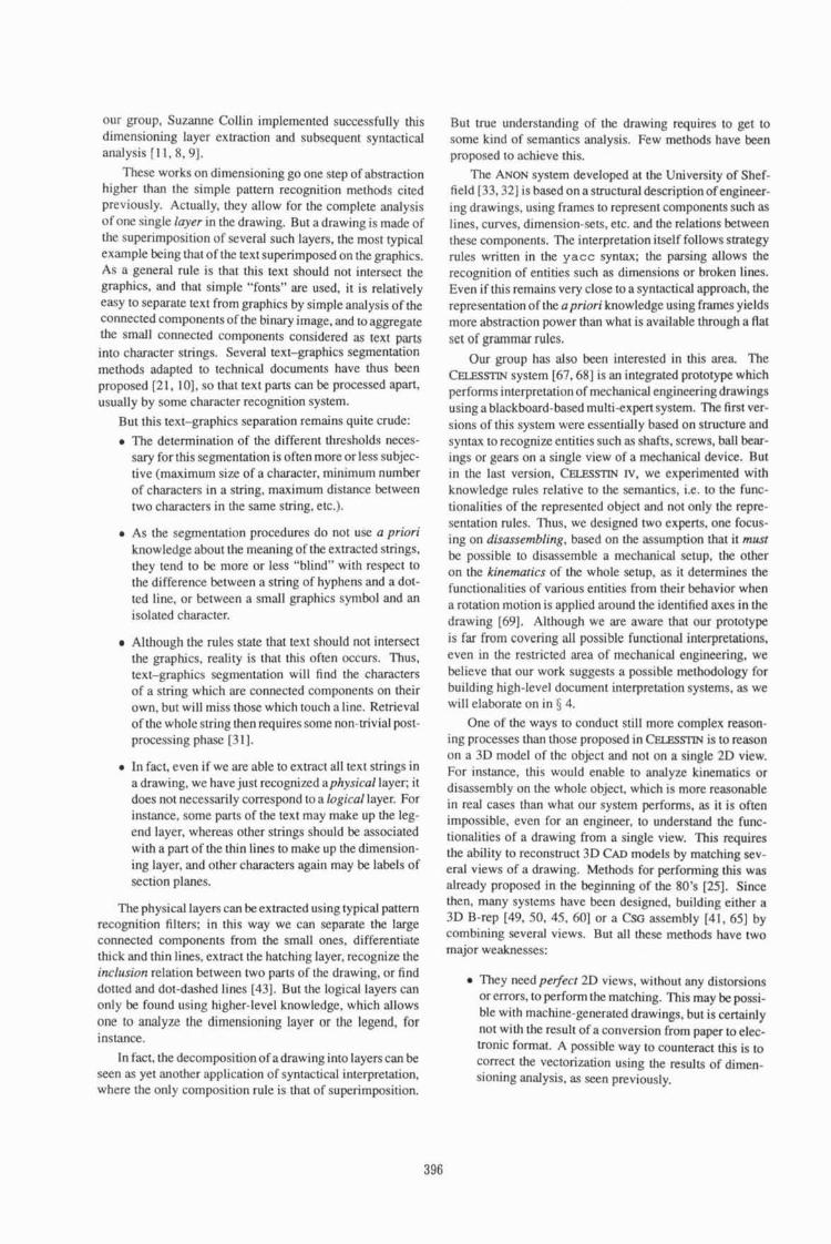
These works on dimensioning go onc step of abstraction higher than the simplc partem recognition merhods cited previously. Actually. they allow for he complete analysis of one single laycr in the drawing. But a drawbrig is madc of [he superimposirion of several such Layers, the most typical example k ing that of lhc text superimposed on thc graphics. As a general rule i s that this text should not intersect the pphics . and that simplc "fonts" are used. i t is relatively easy to separate lcxt from ~ a p h i c s by simplc analysis of the connected components of the binary image. and to aggregate [he small connected componenrs considered as text p;vts into character strings. Several text-graphics aepcntation methods adapted to technical documents have thus k e n proposed [2 1, 101. so that text parts can bz processed apart. usually by some character recognition system.
But this text-graphics separation remains quite crude:
* The determination of the different lhresholds neces- sary for this segmentation is often more or less subjec- live (maximum size of a character. minimum number of characters in a string. maximum distance between two characters in the same string. ctc.).
As the segmentation procedures do not use a priori knowledge about the meaning of the exlractcd slrings, !hey tend to lx more or less "blind" with respect to !he difference ktween a string of hyphens and a dot- ted line, or between a mall graphics symbol and an isolated character.
a Although the rules state that lext should not intersecl rhe graphics. reality is that this oftcn occurs. Thus. [ex[-graphics segmentation will find the characters of a string which are connected components on their own, but will miss rhose which touch a line. RelricvaE of the whole string then requires some non-aivial past- processing phasc [ 3 1 1.
In fact, even if we are able to extract alI text strings in a drawing, we have just recognized aphysical layer; i t does not necessnrily correspond to a Ingical layer. For instance, some parts of the lext may make up the leg- end layer. whereas other strings should he associated wirh a pm or the thin lines to make up the dimension- ing layer, and other characters again may be labels of section planes.
The physical layers can be extracted using typical pattem recognition fil?ers; in this way we can separate the large connected componenrs from the small ones. differentiate thick and thin tines. extract the hatching layer, recognize the incfttsron relat~on 'between two pans of the drawing, or find dotted and dot-daqhed lines [431. But the logical layers can only be found using higher-level knowledge, which allows onc to analyze the dimensioning layer or the legend, for i nstanoe.
In fact. the decomposition of a drawing into layerscan be seen as yet another appricarion of syntactgcal interpretation, where the only composition rule is that of superimposition.
Rut true t~nderstanding of rbe drawing requires to get to some kind of semantics analysis. Few methods have been pmpsed to achieve this.
The ANON system developed at the University of Shef- field [33,32] is bawd on asmctural description of engineer- Ing drawings, using frames to represen1 components such lines, curves, dimension-sets, erc. and h e relalions between these components. The interpretation itself follows saategy n~les written in the yacc syntax; the parsing allows thc recognition of entities such as dimensions or broken lines. Even i f this remains very close to a syntnctical approach. the representation ofthe apriori knowledge using frames yields more abstraction power than what is availabte through a flat ser, of gramma rules,
Our p u p has also been interested in this area. The CXIZWIW system [h7,6Rj i s an inte~ated prololype which pcrfoms interpretation of mechanical engineering drawings using a blackboard-based multi-expert system. The fitst ver- sions of this system were essen~iaily based on structure and syntax to recognix enti ties such a shafts, screws, ball hear- lngs or gears on a single view of a mechanical device. Rut in the last version, C E L E S ~ IV, we exprimented with knowledge rules relative to the semantics, i.e. to thc func- tionalities of the represented object and not only the repre- sentation rules. Thus, wc designcd two expeas, one Focus- ing on disassembling, based on the aqsurnption that i t mud be possible lo disassemble a mechanical setup. the olher on the kinematics of the whole setup. as i t determines [he funcdonalities of various cntiries from rhcir behavior when a rotation motion is applied around the idenlified axes in the drawing [hP]. Although we are aware that our prototype is far from covering all possible functional interprelatjons, even in the restricted area of mechanical engineering. we klicve that our work suggests a possible merhodology for building high-level documcnt interpretation syctems. ac we will elahrare on in 5 4.
One of the ways to conduct still mom complex reason- ing processes than those proposed in C X U S ~ is to reason on a 3D model of thc ohjcct md not on a single 2D view. For insrancc. this would enable to anmlyzc k~nernatics, or disassembly on the whole object. which is morc reasonable in seal cases than what our system performs, as it is often impossible, even for an engineer. to understand the fuw- tionalilies of a drawing from a single view. This requires the ability to reconstruct 3D CAD mdels by matching sev- eral views of a drawing. Methods for performing this was already proposed in the beginning of the 80's 1251. Since then. many systems have been designed, building either a 5D B-rep [49. 50. 45, 601 or a C-G assembly 141, 651 by combining several views. Rut all these methods have two major weaknesses:
They need pevect 2D views, without any distorsions oremors, to perform the matching. This may be possi- ble wirh machine-generared drawings, hut is certainty not wilh he rcsult of a conversion from paper to elec- mnic format. A possiblc way to counteract this i s ro correct the vectori7~l;ltion using the results of dimen- sioning analysis. rn seen previously.

m The matching methods are purely geometric; thus. they work for the "irnag" para of the drawing hut fail an rbe "linguistic" p a . For instane, if a ball bearing is represented by a conventional symbol an one view, the lines making up this symbol will cenainly no! match with corresponding lines on another view! 11 is therefore necessary to analyze a% much symbolics as possible on each single view and to combine the geo- metric matching techniques uscd so far with semantic information yielded by othcr sources of knowledge.
In conclusion. it i s cviden~ that there i s still a lo[ of work to do to achieve really useful automated understanding of engineering drawings, even i f one restricts oneself to il limited technical field. But 1 hope that I have made the challenges interesting enough to convince several people that it is possible and that there is a lo1 of exciting research to do in this area.
3.2 Schemas and Diagrams
Diagrams havc heenextensively s(udied by many groups. Most systems recognize electrical or electronics schemes hy using simple knowledge about the representation rules of such documenrs (a set of possible symhols connected by lines). There are numerous symhol recognition techniques available, based either on classification methods [ I 7.471, on purety smctural attributed graph matching [24. 23. 421 or on hybrid patfern recognition methods [441. Some of rhese systems aim not only at recognizingeach individuaE syrnbal, but dse at analyzing the whole diagram. Fahn el al. [I 91 apply syn~actical analysis to the understanding of electronic circuit d i a~ams . Shimotsuji et al. [h2] and Kato et al. [40J use different layers OF knowledge to recognize hand-drawn schcmes. Futatsurnata et a!. [22] use a cla~sification-based method to analyze plan1 d ia~ams .
Acrually, one of the possible uses rs i contcxrual knowl- edge in such systems is the delimitation of cand~date areas in thc drawing whcrc a symbol has to he lookcd for. Most ex- isting systems are bawd on very rudimcnmry heuridrs. like the supposed size of a symbol. the presence of srnalI white loops in it [57], or the simple fact that everything which i s not a long line segment is supposed to helong to a syrn- bol [471. For specific applications. it might be possible to use much more tnic semantics, such as hypotheses about the expected symbls connected to a symhol already recognized or the generat consistency of the represented circuit.
Rut few systems try to reach thisfunctionoliry level, i.e. LO understand how the represented circuirry works. Ooty limited experiences have been done in that field. Murase and Wakahara [54] anatyze flowcharts and logic circuit di- agrams. Simple semantic rules are used to recover fmm erroneous symbol recognition: for inslance, basic knowl- edge about the "meaning" of different flowcharl symbojs leads to rejecrion of some inconsistent combinations. such as a terminal syrnhol located at a branch of a process flow. These inconsistencies are defined from knowledge about valid and invalid algorithms. However, these rules remain essentially syntactical.
RenjamitI er al, use severaI levels of knowlcdpe in their system for interpretation oftelephone outside plant drawings for Bell Canada IS]: syntactical and structural rulesdescr~be the various kind$ of symbols and relations betwccn [hem. whereas higher-level rules describe the "meaning" of these symbols and the consistencies which have to exist krween tbc corresponding entities i n the real-world application.
It may actuaEly hc tooarnhitious ro hope for much higher level interpretations in this clrtrs of doct~ments: whercaq a mechanicd engineer or an architect is able la ~nderscar~d a drawing made of orthogonal projections. 11 is not sure that an electrical engineer is able to tell what a complex electronics circuit does by just looking at its schcrnal When human expertise fails, can wc expect the computer lo do beflcr? Rltt there are certainly still new results to gci out of !his area, by basing oneself on aEl available knowledge ahour the way humans tmderstmd diagrams [52).
3.3 Maps and charts
The analysis of maps is oitcn aimed at converting pan of rhc information they conlain to some Geographic Infnrma- !ion System (Gts). We already menfioncd the irnpoflmce of layer segmentation for orlhogonal projections: rliis hecomes crucial in Lhc case of cartography. as maps usually contain many superimposed tayers, while the host application only requires the information contained in one nr two of them. Examples of layers which may be OF inreresr are mad net- works [35, 26. 29. 30, 361. topographical infamatien such as elevation curves 1721 or utilities distribution 1701. l o a31 these examples, the layer of interest is essentially composed of a set of attributed lines and pattern recognition techniques can be used. A typical example of str~zctural analysis i s the extraction of drainage vectors from elevation dam. using ctustering md linking or vector chains extracted from the elevation data map 1.591.
It is also possihle lo use other computer-vision related techniques for some applications; For instance, when color is used to code different regions of interer;r, region seqenta- tion techniques are very efficient to extract the correspond- ing tayers [I R]. Another example wherc qcvcral teams have contributed is the matching between aerial or satellltc Im- agery and maps. with all the usual problems of modeling the sensors and the geometry of the observation. finding matching features [20, 461 and i n t e ~ a ~ i n g all that in the Gts [53].
But in some applicalions, still higher level information must he retrieved; for instance. the analysis of cadxqtsal information (city maps) may require a very gnod prccis~on i n the restrlts of vectorization and a perfect rccognition 06 all numbers of land parcels. as this iniomation may k used in Iepl exes 161. There h a k e n quite a lor of activity precisely in thir area nf cadastral m a p . To rhe contrary of engineering drawings, there arc seldom rwo cla%se~ of line thicknesses, but ~t IS nevertheless mportant to find thc hatched areaq, usually representing buildinys, and liencc to remove the hatching layer irom the set ortines to be a n a I y ~ ~ d at later stages. In our group. Dominiquc Antoine dcsigned a system based on procedural networks. which extracts the

hatching layer first. then finds Lhe parcels on which [he buildings are located. and finally groups the parcels into blocks of properties bordered by streets [I, 21. The Japanese system MARIS is also dedicated to such city maps; it is deryged as a set of specialized procedures which cooperare in recopnizing houses. streets. elevation curves. road lines and so on [63].
When it is crucial ro recognize the hatching layer on the one hand and the completc tcxlual annotations on the other hand (as the ntsmbers of the parcels have a legal mean~ng), the problem or layer separarion becomes very crucial, and ir is rendered stifl more difliculr by the Fact that on such maps, text tends especially often to touch the graphic lines (usunlly the hatching). I t is therefore not surprising that two of the reams having hililt the most elaborate systems for analysis of city maps have given spcial atlention to the segmentation of text even when it touches the pphics, by fine-tuning their low-level processing steps, such as vectorization:
Boatto eral. [h] have a system which suesses accuracy in the recognition of the borders between parcels. An intcrmediatc coding of the lines yields a graph which i s searched for sets of regularly spaces lines corre- sponding to hatching. Only the lines which do nor &long lo this hatching layer are vcctori~td and inter- aclively correclcd when necessary. Symbls touching the graphics are cxuacled by search for small charac- reristic subgraphs; characters and other symbols are then recognized by an OCR module. The higher-level analysis can thcn be performed by simple graph pro- cessing merhods. with attributes given hy rhe recog- nizcd text.
Shirno~uji er al. [h I ] propose a similar system. but for Japanese maps containing information about electric power distrihetion. As in the previous method. the vectorization process uses an intermediarc data sbxc- rure, called in the present case primitive lines, which describe as exactly as possible the line fragments in the image. Symbols and characters arc then recognized hy gnuping characteristic features in this structure, even if they touch the graphics. The different kinds of lines are also interpreted according to their semantics (cable lines. map line. . . ).
The analysis of various maps to convcrt them into GFS format may be still much more challenging lhan that of CAD conversion for engineering drawinps, considering the p a l variety of information which may be extracted from maps and the: high Ecvel olsymbolism used 10 represcnr this information. ConccptualEy, maps are aclually no! so far from engineering drawings as they both represen! a projection of a scene on a planc. But when 3D information is present in maps. il is nut rcprcsented by the projection from several viewpoints but in much more "linguistic" ways: elevation d a ~ a curves, altitude writfen at several points of the map, etc. More generally, the wtio between imagc and language in a map tends to be much more in favor of tanguag lhan what is the c x e in eng-ineering drawings. Hence, it I S obvious that tea1 understanding can only k achieved if this linguistic
interprctarion is correctly taken into account, In addition, we have seen that maps are often a superimposidon of many layers, which increases the difficulty of segmentation.
4 TOWARDS A METHODOLOGY?
As we have ~ricd to stress throughour this anicle. drafrs- manship is no! only a geometric activity: it also a language. Hence technical document analysis systems aiming at a real understanding of the engineering drawing, the diagram or !he map must takc into account both Its image part and its language part. This compzls us to go kyond usual pattern recogn~tion techniques. For instance, after vectnrization of an eng~neering drawme, it is natural to try to connect vec- tors at junction points in order to exWac1 longer lines; but we must take into accounl !he fact that some vectors heIong to the imagc p a . that is to the line drawing representing the orthographic projection of wme 3D surfaces. whereas orher vectorr betong to the language part, for example the hatching lines labeling an area as a section in matter.
The question which comes to mind is rhen: is rhere a general methodology alIowing to cornbicre these different kinds of knowledge. in order to go all the way from pix- els to semantics in an ordered manner? We are far from claiming that we have a definite answer to this question, bu! our various experiences have led us into decomposing the reasoning process in document interpretation along two axes:
The first axis corresponds to the spalial (or image) vision: it consists in grouping elemen~ary features into hieher-[eve[ ones. This grouping can be performed by sirnplc structural matching or by some synractical pattern recognition techniques.
Thc second axis corresponds to the "reduction" of symbolic information (the language part) into new features, which can then he manipulated by new spa- tial grouping t~ols , and so on.
The whole reasoning pmcess can then k seen as the proms- sive use of different leveEs of semantics to induce new srruc- iiires, on which an appropriate syntax can k applied [a].
TO illustrate this, Fig. 1 summarizes the different steps and levels of reasoning in our C I ~ L E S ~ system. On the first level, we have pixel processing, where a set of opera- tions can be performed to clean rhc imagc, label connected components. and so on. Once we introduce the low-lcvcl knowledge that such drawings are mainly made o l lines, we can go up to the second Icvet. where vectorization pro- vides a new hasic structure, the vector. Different struclural and syntacdcal rules can he applied on vectors. allowing for separating thin and thick lines. finding dot-dashed lines, etc. We next defined a new basic smcture. the block 16Xj. which cames from the fact that all closed minimal polygons in thick lines either represent matter or empty space. On these blocks. new structuring operations can he defined, such a5 a syntax ro rccagnile entifies [69]. We could have added still

Figure 1 : Spatial ancl symbolic reasoning in CELF,~STIN I tlgrrc kindly provided by !'. VaxlviEre).
a higher lcvcl of infornlation reductinn, whcrc we would have thc seaconing ahouf krncrna~ics and disascrnhl ing.
Howevcr, it i q not d e a r lo IIS iT this scheme is gcncral cnouph tn desc r ik any reawning conilt~cted to a n d y 7 ~ a technical document. Evcn sf if 3s. anorher open qzeeition remains: For a giver1 application with wet1 defined intcrpre- lation needs, do wc have a general methodnlogy to define the right strwcti~rcs. rhc right syntax on thcst: strucri~rec. and the appmpriale syrntxrlics to use rrom one levcl IO the other? I welcome any answer. evcn partial. tn these questions. . .
ACKNOWLEDGMENTS
hcrirlitcd from thc spirit of this work. 1 look forward to still rnuclr cltrwr coopcr;tlion hetween r > ~ ~ r prozlp md Dov's in the comlng rnnnth? and ycars.
Our group ttns hencfitcd in the pas1 years from various grants ant! orher financial suppon for our work on technical docu rnenr analysis; this wppnr t IS gratefi~lly acknowledged, with special memton tn a "srrmuIatinn conlract" from Insritrrt Narional Polyrerh~riqut- de Lorraine, a gnnr from MinisrPw de In Rechercl~e er d~ In Teclznaloeie. a study mant from IBM Fnncc to E S m . an enp~nccrinp school in Nancy where wc built Ihe C E L ~ ~ S S ~ syqlem. and of course continuous support from CRIN/CNRS and INR!A l ~ r r a i n e .
References In tl~e past ycars, several people have becn working I ) D. Antoine. CIPLAN: A Modcl-Rased Sy~ te rn with
with me on variol~s aspccts of technIcd docl~mcnt analyqis Original kn t i t r t s for Understanding French Plats. In and have hence contributed to our group's expertisc in this
Praceedirig.~ of l;i,:rr Itzrermrinno! Conferenre on Doc- domain* 1 would espcciaIly likc to thank my fomier and
umcnr Analysrs. Sainr-Malo. Fronrc, volume 2, pnpcs prcscrtt PhD studcnts Dorniniquc Anlaine. Suzanne ColIin. 6.17455. 1 Y'I I . Anja Habacha and Pascal VrutiviEre for their contrihulion to [his expenise, in varloils application domnrns, as can be seen by the bibliographical rcfcrcnccs to their work in this. mi- cle. Many long discussinns with ' VaxiviEre have been cs- pecially useful to help rnalurin? the proposcd methodology for document understanding. T l ~ c classif cation of technical documents into v.uious cstugorics (f( 3 ) was first propored by my colIcague AMcl Eel f ti. whose rcsrarch group works on struaured rlncumrnr analysic and charactel. recognition. when we preparcd iogcther a course nn dr~curnent iinnly-
121 D. Anroinc. S. Collin. and K . Tombre. Analysis of Technical Documents: The REDRAW Syslcrn. In H.S. Ra~rd , F l . Runkc.. and K. Yamamoto, cditnrs, Strrrr!rcred Dorl~nr~nt Image Anal,vs~s. Springer Ver- lag, 1992. To appc;~.
1-1"s. Rnird. 11. Runkc. and K. Yarnamorn. editors. Srrrrrrrtred Docrtmcnt I n l a ~ r Anahsrs. Sprinpcr Vcr- Ing. 1997.
sir. It ha* also k e n rewartl~ne, lo n n collahrating will1 ,41 A. Relaid nmblr. Anriyre dr doc,lmenls : D o v Dori, from Tcchnion University. Hsira flsracl I: this ar-
dc I'lnlage A ia ~Pmantiquc. In Bi~r+? 80 - Arte.~ d e tick w a ~ wrirtcn a wcek after we had complctcd together
CNED'92 : Trarrcrnenr de I' ksrr~rre cr des documenb, a survey on Icchnical docurnrnr analvqis. and i t certainly Nonry, p a p 7-1'). Juillct 1992.

[5 ] D. Benjamin, 0. Forgues, E. Gulko, J.R. Massicotte. and 6. Meubus. The Use of High-Lvel Knowledge for Enhanced Entry of Engineering Drawings. In Pro- ceedings of 9th Infernational Co@e~nce on Purrern Recugnirion. Rome (Italy). pages I I % 124.1988.
[6] L. Boana, V. Consoni, M, k l Buono, 5. Di Zenzo. V. Errno, A. Esposito, E Melcarne, M. Meucci, A. MoreEli, M. Mosciatti, S. Scarci, and M. Tucci. An Interpreration System for Land Register Maps. IEEE COMPUTER Magazine, 25(7):25-33, July 1992.
[7] V. Cappellini, F. Ramigni, and A. Mecocci, A System for Automatic Drafting Encoding. In Proceedings of IAPR Workshop on Computer Vision, Tokyo (Japan), pages 173-17R, 1988.
[8] S. Collin. Interpr€talion de la cotation des dessins tech- niques par analyse syntaxique. Thtse de doctorat, In- sti rut National Pol ytechnique de Lorraine, Vandceuvre- lb-Nancy, Jan. 1992.
[9] S. Collin. Syntactical Analysis of Technical Draw- ing Dimensions. In PAPR Intemtioml Workshop on Structural and Synractic Pattern Recognirion, Bern (Switzerland), August 1992.
[IO] S. Collin and K. Tombre. Image Segmentation Us- ing Connected Components: for Document Analysis. In Proceedings oflFACSIIMACSIIFORS Enternational Symposium on Advanced Information Pmcessing in Auromatic Contml, Nancy, France, volume 2, pages 166-1 70,19R9.
[l l ] S. Collin and P. Vaxivitre. Recognition and Use of Dimensioning in Digitized Industrial Drawings. In Proceedings of Firsi Intertmfionul Conference on Doc- umenr Analysis, Sainr-Mulo, France, volume 1 , pages 161-169.199t.
1121 IEEE COMPUTER Magazine. Special Issue on Doc- ument Image Analysis Systems, Volume 25. Number 7. July 1992.
[ I 31 D. Dori. A SyntacticKjeometric Approach to Recog- nition of Dimensions in Engineering Drawings, Corn- purer Vision, Graphics andlmagc Processing, 4727 1 - 291,1989.
[I41 D. Dori. Self Structural Syntax Directed Pattern Recognition of Dimensioning Components in Engl- neering Drawings. In Pre-proceedings o f f A P R Work- shop an Syntactic and Stmctwal Pattern Recognition, MurrqvHill, NJ(USAJ, pages 88-1 12, 1990,
1151 D. Dori. Symbolic Representation of Dimensioning in Engineering Drawings. In Proceedings of Firn In- ~ernorionul Conference on Documem Analysis. Saint- Malo, France, volume 2, pages 1000-10 10,1991-
[l6] D. Dori and A. Pnueli. The Grammar of Dimensions in Machine Drawings. Computer Vision, Graphics and Image Pmcessing, 42: 1-1 8. 1988.
[ I 77 K. Eikvil and T. Taxt. Simultaneous Recognition of Class and Rotation Angle of Raster Symbols. In Pro- ceedings of 71h Scondinavion Conference on Image Analysis, Aolhorg (D~nmark), pages 461 -468,1991.
[EX] R. Espelid, N. A. Alvsvmg, J. Eileng. and T. Skauge. Automatic DigitizingoT the Colour-Layer of Themalic Maps. In Proceedings of lAPR Workshop on Machine Vision Applicarions, Tom (Japan). pages 299-302, 1990.
[I91 C.S. Eahn, J.F. Wang, and J.Y. Lee. A Topology- Based Component Extractor for Understanding Elec- tronic Circuit Diagama. Cornpurer Vision. Graphics andimage Processing. 44: 1 19-1 38.1988.
[20] M.A. Fischler, J.M. Tenenbaum. and H.C. Wolf. De- tectionoFRoads and linear Structures in low-resolution Aerial Imagery using a Multisource Knowledg Inte- gration Technique. Computer Vision. Graphics and Image Processing, 15:201-223, 1981.
[21] LA. Fletcher and R. Kasturi. A Robust Algorithm for Text Sning Separation fmm Mixed TexdGraphics Images. IEEE Transacfions on P M , 1 O(6):9 10-9 1 8, 1988.
[22] T. Futatsumata. G. Shichino, J. Shibayama, and A. Maeda Development of an Automatic Recog- nition System for Plant Diapms. In Pmceedings qf SAPR Workshop on Machlnc fision Applicarions, Tokyo (Japan). pages 207-2 10, 1990.
/23] A.H. Habacha. Structural Recognition of Disturbed S yrnbls Using Discrete Relaxation. In Pruceedings of First International Conference on Documenr Analysis, Saint-Malo, France. volume 1, pages 170- 178. 1 99 1.
[24] A.H. Habacha and K. Tombre. Structural Symbl Recognilion. In Proceedings of 7th Scandinavian Con- ference on Image h l y s i s , Aolbarlq (Denmurk), vol- ume 1, pages 4 8 6 4 9 3 , August 199 1.
[25] R.H. HaraIick and D. Qrteeney. Understanding En- gineering Drawings. Computer Graphics and Image Procersing, 20:244-258. 1 9 82.
[26] T. Hayakawa, T. Watanabe, Y. Yoshida, and R. Kawaguchi. Recognition of Roads in an Urban Map by Using the Topological Road-Network. In Proceed- ings of IAPR Wnrkd~op on Machine Vision Appiica- rions, Tobo (Japan), pages 2 15-2 1 8,1990.
[27] 1. Hofer-Alfeis and G. Maderlechner. Automated Con- version of Mechanical Engineering Drawings to CAD Models: Too Many Problems? In Proceedings of I M R Workshop an Camprrter fixion, Tokyo (Japan), pages 206-209, 1988.
[18] Proceedings of First International ConfPsence on QOC-
umenr Analysisand Recugnirion, Sainr-Mulo (France). Paris. 199 I. AFCET.

[29] M. Ilg. Knowledge-Based Understanding of Road Maps and other Lines Images. In Proceedings of 10th Inrernarionol Conference on Paitern Recognition. At- lantic Civ, EJJ(USA), volume 1, pages 282-284,1990.
1301 M. IIg and R. Ogniewicz. Knowledge-Rased Interpre- tation of Road Maps Based on Symmetrical Skeletons. In Proceedings of lAPR Wnrkshop on Machine Ksion Applications, T o l y (Japan), pages t 6 1 - 164. 1990.
1311 S.H. Joseph. On the Extraction of Tent Connected to Linework in Document Images. In Pmcecdings of Firsr Interna~ional Conference on Document Analysis, Saint-Mulo. France, volume 2. pages 993-999. 199 1.
[32] S.H. Joseph and T.P. Pridmare. A System for the Inter- pretation of lmages of Graphics. In Pre-proceedings of FAPR Workshop on Synractic andSiructura1 Partern Recogniiion, Mrdrray Hill, NJ (USA), pages 154- 164, 1990.
[33] S.H. Joseph, T.' Pridmore. and M.E. Dunn, Towards the Automatic Interpretation of Mechanical Engineer- ing Drawings. In A. Rarrett, edifor, Compurer K.~ion and image Prncessing. Kogan Page, 1989.
[34] M. Karjrna. K.S. SadhaI. and T.O. McNeil. From Pa- per Drawings to Computer-Aided Dedp. 1EEE Com- purer Graphics and Applicoriolls, 5(21:23-39. 1985.
1351 R. Kashrri and I. Alemany. Information Exiraction from Image? of Paper-Based Maps. IEEE Tsonsoc- tions an S o f ~ r c En~incering. 14(5):67 1675, 1988.
1361 R. Kns~uri. R. Fernandez, M.L. Amlani, and W.- C. Feng. Map Data Processing in Geographic In- formation Systems. IEEE COMPUTER Magazine, 22(12):10-21, 1989.
1311 R. Kasturi and L. P'Gorman. Documenl Image Anal- ysis: A Bibliography. Machine Vision andAppIicu- t iow, 5(3):23 1-24>, Summer 1992.
13R1 R Kasturi. R. Raman. C. Chennubhotla, and L. O'Gorman. Document Image Analysis: An Overview of Techniques lor Graphics Recognition. in Pre-proceedings of lAPR Workshop on Syntactic and Sflucrnral Partern Recogni~ion, Murray Hill, hrl (USA), pages 192-230. 3 990.
[39] R. Kasturi, S. Siva, and L. O'Gorman. Techniques for Line Drawing Interpretation: An Overview. In Pro- ceedings of MPR Workshop on Machine Ksion Appli- cations. Tnkyn (Jopnn), pages 1 5 1 - 1 60. 1990.
[40] H. Kato and S. Inokuchi. The Recognizion Method for Roughly Hand-Drawn Logical Diagams Based on Hybrid Utllizar~on of Mul ti-byered Knowledge. In Proceedings of l O f h Internarionnl Conference on Par- tern Recognition, Atlanric City NJ (USA). volume 1, pages 578-582. 1990.
1411 K. Kitajima and M. Yoshida. Reconstruction of CSG Solid from a Set of Orthographic Three Views. In Pro- ceedings of IEEE Internal ional Conf~rencc on Systems Engineering, Kobe, Japan, pageq 220-224, Seprember 1992.
[42] F! Kuner and B. Uekmiter. Knowledge Rased Panern Recognition in Disturbed L ~ n e Images Using Graph Theory Optimization and Predicate Calculus. In Pro- cecdings of 8th Inrernational Conference on Pattern Recognition, Paris {France), pages 24Cb243. 1986.
1431 C.P. Lai and R. Kasturi. Detection of Dashed Lines in Engineering Drawings and Maps. In Proceedings of Firsr Internati~rrcrl Conference on Document Analysis, Sainr-Malo, France. vofume 2, pages 507-5 15, 1991.
[44) S.W. Lee. J.H. Kim. and F,C.A, Grwn. Translation-, Rotation- and Scale-invariant Recognition of Hand- h w n Electrical Circait Symbols with Attributed Graph Matching. rn Pre-proceedings of IAPR Wark- shop an Syntoair and Strrrctural Pattern R~ce~nirion. Murray Hill, MJ (USA), pages 273-292, 1990.
[4SJ R. Lequette. Construction automatique de solides partic de vues orthogonales de type dessin industriel. Thhe de doctorat. UniversitC de Grenoble, 1987.
[46] S.Z. Li, J. KittEer, and M. Petrou. Matching and Recog- nition of Road Networks tmm Aerial Images. In G. Sandini. edifor. Proceedings of Second Eltropean Conjference on Compurer Usion, Sonra Mar~herifo Ligure (Ifah). pages 857-86 1 , 1992. Ixcturc Notes in Cornpuler Science. Vol. 588.
[47] X. Lin. S. Shirnotsuji, M. Minoh, and T. Sakai. Effi- Fient Diagram Understanding with Characteristic Pat- tern Detection. Cornpurer Vision, Graphics ondImage Proce,~.~ing. 30384-1 06, t 9R5.
[48j W. Lu. Y. Ohsawa. and M. Sakauchi. A Database Capture Systcm for Mechanical Drawings Using an Efficient Multi-dimensional Graphical Data Structure. In Proceedings of 9th International CorrJerence on Par- fern Recognition, Rome (ltaIy). pagcs 2 6 2 6 9 . 1988.
[49] D.B. Lysak and R. Kasturi, lntcrpretation of Engi- neering Drawings OF Polyhedral and Non-poly hedral Objects. In Proceedings of Firs1 Inrernnr ion01 Con- ference on Document Analysis, Sainr-Malo, France. volume I, pages 79-87, 1991.
[50] E. Marti, J. Reginchs, I. h ~ z - K r a h e , and J.J. Vil- Ianueva. A System for Intcvtetation of Hand Line Drawings as Three-Dimensional Scene for CAD Fn- put. In Pwceedinxs of First International Confemncc on Docurnenr Analysis, Saint-Malo, France. volume 1. pages 472480. 199 1.

[S I ] U.B. Mokate and R. Kasturi. An Algorithm fotRecog- nition of C~rcles in Graphics. Computer Engineering Technical Repon TR-88-061, The PennsyIvania State University, Department of Electrical Engineering, Uni- versity Park, Pennsylvania 16802,198R.
[52] F.S. Montalvo. Diagram Understanding: The Intersec- tion of Computer Vision and Graphics. Technical RC- pon 873. Massachusetts Insritute of Technolagy, 1985.
[53] S. Murai, S. Viseshsin. Y. Honda, M. Xi, M. Tak- agi, and S. Ochi. 3D Application in Remote Sensing and Geographic Information Systems. In InremtfonaI Symposium on Three Dimensional image Technology and Ans. Tokyo. Japan, 5-7 Feb 1992.
[54] H. Murase and T. Wakahara. Online Hand-sketched Figure Recognition. Partem Recognition. 1 9(2): 147- 160,1986.
1551 Machine Vision and Applications. First Spcial Issue on Docurnen1 Image Analysis Techniques. Volume 5, Number 3. Summer, 1992.
[56] V. Nagasmy and N.A. Lmpna. Engineering Draw- ing Processing and Vectotizatioa System. Cornpuler Vision. Grcrphics and Image Processing, 49(3) 379- 397,1990.
[571 A. Okazaki, T. Kondo, K. Mori. S. Tsunekawa, and E. Kawamoto. An Automatic Circuit Diagram Reader with Loop-Shucture-Based Symbol Recognl- tion. IEEE Transactionr on PAMI, 10(3):33 1-341, 1988.
[58] D. Pao. H.F. Li, and R. Jayakurnar, Graphic Ra- turns Extraction for Automatic Conversion of Engi- neering Line Drawings. Fn Proceedings of First In- terna$ioml Conference an Document Analysis, Saint- Malo, France, volume 2, pages 533-541.199 1.
f59] W.W. Seemuller. lShe Extraction of Ordered Vector Drainage Nelworks from Elevation Dam. Compaier Vision, Graphics and Image Processing, 47:45-5 8, 1989.
[6OJ T. Senda and Y. Arirnitsu. Automatic Reconstruction of Solid from a Set of the Orthopphical Three Views. In Proceedings of IEEE International Conference on Systems Engineering, Kobe, Japan, pages 229-233. S e p t e m k r 1992.
[61] S. Shirnotsuji, 0. Hori, M. Asano, K. Suzuki, E Hoshino, and T. Ishii. k Robust Recognition Sys- [em for a Drawing Superimposed on a Map. IEEE COMPUTER Magazine, 25(3):5&59. July t992.
1631 S. Suzuki and T. Yamada. MARIS: Map Recogni- tion input System. In Proceedings of lAPR Workshop on Computer Vision, Tokyo (Japan), pages 42 1426 , 1988.
[MI K-Tombrcand !? Vaxiviere. Saucture,Syntaxand Se- mantics in Technical Document Recognition. In Pm- ceedings of First lntcrnarional Coqfertnce on Docu- ment Anahis , Sainr-Malo, France, volume 1. pages 61-69. 1991.
[65] K. Torniyarna, T. Nakamura. and T. Koexuka. Auxil- iary Cines in Three View Drawings for 3D Shape Re- construction Using CSG Method. In Proceedings qf IEEE Internu~iofial Conference on Sysrems Engineer- ing, Kobe, Jupm, pages 250-256, Septemkr 1992.
[66] S. Tsujio, T. Onn, and S.S. Lee. Computer-Aided Drawing Check For CAD Systems - A Method for the Checking of Dimensions in Multiview Mechanical Drawings. In Pr~ce~dings of IEEE Iniernational Con- ference on S>~.~iems Engineering. Kohe, Japan, pages 234237 , September 1992.
[67] I? Vaxiviere and K. Tombre. Interpretationof Mechan- ical Engineering Drawings for Paper-CAD Conver- sion. In Proceedings of 1APR Workshop on Machine Vision Applicarions, Tokyo (Japan J, pages 203-206, 1990.
[6R] P. Vaxivitre and K. Tombre. Celesstin: CAD Con- version of Mechanical Drawings. IEEE COMPUTER Fnogozine, 25(7):rKi54, July 1992.
I691 P. Vaxivitre and K. Tombre. CELESSTIN 1Y: Knowledge-Based Analysis of Mechanical Engineer- ing Drawings. In Proceedings of IEEE Intcr~rional Conference on Systems En~ineering, Kobe. Japan. pages 242-245, September 1992.
[70] K. Wakimoto, Y. Maeda, M. Shima, A. Maeda. and N. Chikada. A Ulility Map 'kansformation System Based on Map Understanding. In PmceedingsofIdPR Workshop on Computer Vision, Tokyo (Japan). pages 220-223. 1988.
[71] LS. Wotfe and J, de Wyze. An Update on Drawing Conversion. Computer Aided Design Repon. R(6): 1- 11. 3988.
[72j E. YII-J3ii;iski md H. Ahonen. Knowledge-based And- ysis of Line Drawing. In Proceedin~s of 61h Scondi- navian Conference on Image Analysis. Oulu (Finland), pages 774-777, 1989.
1621 5. Shimotsuji. S. Tarnura, and S. Tsunekawa. Model- based Diagram Analysis by Generally Defined Primi- tives. In Proceedings of 6th Scandinavian Conference on Image Analysis, O u b (Finland), pages 1034-1 04 1, t 989.