Technical Documentation of the Microphone Array Mark III
60
Technical Documentation of the Microphone Array Mark III ROCHET Cedrick Information Access Division National Institute of Standards and Technology * September 21, 2005 * NIST, 100 Bureau Drive, Stop 3460, Gaithersburg, MD 20899-3460., www.nist.gov
Transcript of Technical Documentation of the Microphone Array Mark III

Technical Documentation of the Microphone ArrayMark III
ROCHET Cedrick
Information Access DivisionNational Institute of Standards and Technology ∗
September 21, 2005
∗NIST, 100 Bureau Drive, Stop 3460, Gaithersburg, MD 20899-3460., www.nist.gov

Contents
1 Historic. 41.1 The First Generation . . . . . . . . . . . . . . . . . . . . . . . 41.2 The Second Generation . . . . . . . . . . . . . . . . . . . . . . 51.3 The Third Generation version 1 . . . . . . . . . . . . . . . . . 61.4 The Third Generation version 2 . . . . . . . . . . . . . . . . . 6
2 The Hardware. 72.1 Microboard . . . . . . . . . . . . . . . . . . . . . . . . . . . . . 8
2.1.1 An overview . . . . . . . . . . . . . . . . . . . . . . . 82.1.2 Microphone amplification stage . . . . . . . . . . . . 92.1.3 Digitalization stage . . . . . . . . . . . . . . . . . . . . 112.1.4 Motherboard connection stage . . . . . . . . . . . . . 12
2.2 Motherboard . . . . . . . . . . . . . . . . . . . . . . . . . . . . 132.2.1 An overview . . . . . . . . . . . . . . . . . . . . . . . 132.2.2 Power stage . . . . . . . . . . . . . . . . . . . . . . . . 142.2.3 PROM stage . . . . . . . . . . . . . . . . . . . . . . . . 152.2.4 Clock stage . . . . . . . . . . . . . . . . . . . . . . . . 152.2.5 Data collection stage . . . . . . . . . . . . . . . . . . . 162.2.6 FPGA stage . . . . . . . . . . . . . . . . . . . . . . . . 172.2.7 Memory stage . . . . . . . . . . . . . . . . . . . . . . . 182.2.8 Ethernet stage . . . . . . . . . . . . . . . . . . . . . . . 20
3 The VHDL program for the FPGA. 223.1 The VHDL . . . . . . . . . . . . . . . . . . . . . . . . . . . . . 223.2 UDP . . . . . . . . . . . . . . . . . . . . . . . . . . . . . . . . . 223.3 The Main VHDL program . . . . . . . . . . . . . . . . . . . . 233.4 The capture module . . . . . . . . . . . . . . . . . . . . . . . . 243.5 The sram interface module . . . . . . . . . . . . . . . . . . . . 263.6 The capture_udp_frame module . . . . . . . . . . . . . . . . 283.7 The bootp module . . . . . . . . . . . . . . . . . . . . . . . . . 293.8 The arp module . . . . . . . . . . . . . . . . . . . . . . . . . . 303.9 The response status module . . . . . . . . . . . . . . . . . . . 313.10 The mux4_1 module . . . . . . . . . . . . . . . . . . . . . . . 323.11 The CRC32 module . . . . . . . . . . . . . . . . . . . . . . . . 333.12 The tx_frame module . . . . . . . . . . . . . . . . . . . . . . . 333.13 The incoming message module . . . . . . . . . . . . . . . . . 343.14 The read incoming message module . . . . . . . . . . . . . . 343.15 The MI interface for configuration and status . . . . . . . . . 36
2

4 The softwares on the computer. 374.1 The command and control . . . . . . . . . . . . . . . . . . . . 374.2 The oscilloscope . . . . . . . . . . . . . . . . . . . . . . . . . . 464.3 The library . . . . . . . . . . . . . . . . . . . . . . . . . . . . . 48
4.3.1 mk3array_create . . . . . . . . . . . . . . . . . . . . . 484.3.2 mk3array_comminit . . . . . . . . . . . . . . . . . . . 494.3.3 mk3array_ask_speed . . . . . . . . . . . . . . . . . . . 494.3.4 mk3array_set_speed . . . . . . . . . . . . . . . . . . . 494.3.5 mk3array_ask_slave . . . . . . . . . . . . . . . . . . . 504.3.6 mk3array_set_slave . . . . . . . . . . . . . . . . . . . 504.3.7 mk3array_ask_id . . . . . . . . . . . . . . . . . . . . . 504.3.8 mk3array_ask_promnb . . . . . . . . . . . . . . . . . 504.3.9 mk3array_initparams . . . . . . . . . . . . . . . . . . 514.3.10 mk3array_initparams_wp . . . . . . . . . . . . . . . . 514.3.11 mk3array_fix_drop_X_first_frames . . . . . . . . . . . 514.3.12 mk3array_display_warnings . . . . . . . . . . . . . . 524.3.13 mk3array_normalize . . . . . . . . . . . . . . . . . . . 524.3.14 mk3array_capture_on . . . . . . . . . . . . . . . . . . 524.3.15 mk3array_wait_capture_started . . . . . . . . . . . . 534.3.16 mk3array_get_databuffer . . . . . . . . . . . . . . . . 534.3.17 mk3array_get_databuffer_nonblocking . . . . . . . . 534.3.18 mk3array_get_current_databuffer_timestamp . . . . 544.3.19 mk3array_skip_current_databuffer . . . . . . . . . . . 544.3.20 mk3array_check_databuffer_overflow . . . . . . . . . 544.3.21 mk3array_check_lostdataframes . . . . . . . . . . . . 554.3.22 mk3array_check_capture_ok . . . . . . . . . . . . . . 554.3.23 mk3array_capture_off . . . . . . . . . . . . . . . . . . 554.3.24 mk3array_delete . . . . . . . . . . . . . . . . . . . . . 554.3.25 How to use it . . . . . . . . . . . . . . . . . . . . . . . 56
5 The box. 565.1 Material needed . . . . . . . . . . . . . . . . . . . . . . . . . . 575.2 Dimensions . . . . . . . . . . . . . . . . . . . . . . . . . . . . 57
3

1 Historic.
In this part we are going to see the previous models of microphone arraysthat were developed at NIST.
1.1 The First Generation
The first generation was very primitive. Each Ns microphones were put inparallel. So the output signal was the sum of each microphone. The figure 1illustrates this.
Figure 1: Microphone Array Mark I schematic.
In this case the beamforming was done analogically and at 90 deg of thecenter. The result is a single output analogic signal as seen on the overviewof the microphone array first generation in figure 2.
Figure 2: Microphone Array Mark I.
4

1.2 The Second Generation
The second generation is actually the one currently in use. At the beginningof my internship, I had to build three second generation array to supportthe construction of an advanced meeting room data acquisition facility . Inthe same time I learned how the Smart Flow System works. As you can see,on figure 3 , the system is relatively simple but efficient.
Figure 3: Microphone Array Mark II schematic.
Fast and efficient, DSP is used in signal processing to acquire and pro-cess data. It consists of an A/D converter with a processor, and interfaces.The DSP hardware that will be used in this project has only 64 inputs. Thus,we are restricted to use no more than 64 channels (i.e., 64 sensors).
Figure 4: Microphone Array Mark II.
As you can see on the figure 4, the second generation array has a dis-crete port and a preamplifier for each microphone. The second generationmicrophone array used the analogical preamplifier shown on figure5.
5

Figure 5: Microphone Array Mark II Preamplifier.
1.3 The Third Generation version 1
Figure 6: Microphone Array Mark III version 1.
The objective of the third generation array is to place the preamplifierand analog to digital converter close to the microphones in order to reduceany noise due to the environment. So this new generation uses a com-pletely different design as shown in figure 7
In this new design, the DSP card on the computer becomes obsolete. Inorder to reduce the complexity of design, I decided to separate the problemin two different boards. The first one, the Microboard is in fact, a sound cap-ture device. The second part is a Motherboard which sends, via an FPGA,data from the Microboard to the Ethernet ( cf figure 8).
1.4 The Third Generation version 2
The version 2 is an upgrade of the version 1 where new features have beenadded to respond to the need of the community.
These upgrades are moslty hardware:
• pluggable microphones,
6

Figure 7: Microphone Array Mark III schematic.
Figure 8: Microphone Array Mark III schematic.
• reduce amplification gain to match condition in small rooms,
• hardware gain match between microphones,
• reduced noise,
• microphones powered by a batterie pack or a pluggable card.
2 The Hardware.
All the schematics for the hardware are available in the zip of the boardslayout. It was done under eagle software.
7

Figure 9: Microphone Array Mark III version 2.
2.1 Microboard
2.1.1 An overview
Figure 10: Microboard picture.
On the figure 10 you can see clearly the disposition of the differentstages on the board.
In order to go deeper in the explanations, we are going to divide thisboard into three parts:
• the microphone amplification stage,
• the digitalization stage,
8

• and the motherboard connection stage.
Our major objective is to reduce the noise factor and have the best per-formances at the lowest cost for the converter.
We made the choice of working in SMT in order to have very smalltraces. This will eliminate much electromagnetic interference particularlysince the microphones are high impedance and long conductor runs incurnoise penalty.
An other choice was to make the Microboard in four layers. This kindof technology is far more better to get less interferences since the GND andVCC planes are close to the signal planes. The difference of price betweena 2 and a 4 layer board has been considered but the difference in big quan-tities wasn’t sufficient to really reduce the overall price.
Another choice was to put 8 microphones on the same board. This isbased on the fact that 64 is a multiple of 8, 4 digitizers can share the sameclocks and power supply and the size of the board is reasonable.
Each microphone is spaced with 2cm. The value has been chosen by it’sadequacy to human voice frequency range. So the width of the microphonearray is about 130cm.
2.1.2 Microphone amplification stage
In this part we are going to have a closer look of this stage.How it Works
As you can see from the figure 11, the microphone creates the soundsignal which after is amplified.
The sensors used for the previous microphone array genera-tions are Panasonic WM-52B electret microphones (http://www.mci.panasonic.co.jp/english/prdct/ecm/pdf/wm-53bs_wm-52b_54b.pdf ). They offer a good frequency response forhuman voice frequency range. This microphone needs a phantom powerof 1.5V made by the resistor R1. The resistors R2 and R3 are in place toincrease the isolation between each microphones. C2 is in place to ensurethe quality of the phantow power of the microphone.
The capacitor C3 is cutting the DC part of the signal entering the opera-tional amplifier. I used an OPA2228 series op amps because it’s the combi-nation of low noise and wide bandwidth with high precision. You can findits specification here: http://www-s.ti.com/sc/psheets/sbos110/
9

Figure 11: Schematic of the amplification stage for the left channel.
sbos110.pdf . The OPA2228 is decoupled with the capacitor C1. The R6resistor is here to get the current out of the entry of the OPA2228. The gainis done in two stages: the first one has a gain of 100 done by R7 and R4and the second one done by R11 and R5 has a gain of 6.81 in version 1 ofthe array and a gain 1.2 in version 2. The POT1 component was added inversion 2 to do hardware gain match between microphones.
Since the OPA is powered by the GND and the +5V, a phantom GND at2.5V was created: it’s done by the resistor R10 and R13. The capacitor C7and C8 decoupled it.
The last capacitor C4 removes again the DC component of the signalbefore entering the A/D. This amplification stage is done in double for onestereo digitizer. So you have a left (VINL) and a right (VINR) channel en-tering the digitizer.
10

2.1.3 Digitalization stage
The second stage of the Microboard is made mainly by the PCM1802 ( cffigure 12).
Figure 12: Schematic of the digitalization stage.
I have chosen the Analogic/Digital converter PCM1802 because of its24-Bit Stereo capability, low-cost, single chip stereo Analog-to-Digital Con-verter (ADC) with single-ended analog voltage inputs. The PCM1802uses a delta-sigma modulator with 64x or 128x oversampling, a digitaldecimation filter, and a serial inter-face which supports Slave mode op-eration and two data formats. The reason of a low cost is his range ofwork adapted to the sound. You can find its specification here: http:
11

//www-s.ti.com/sc/ds/pcm1802.pdf .In that part, I just followed the indication given by the documentation
in the worst case scenario. So for more information you can refer to thePDF file given previously except the 100Ω resistor for the signal integrityof DOUT because of the transmission line between the PCM1802 and theFPGA.
Three clocks LRCK, BCK and SCKI are given by the Motherboard:
• LRCK is the sampling frequency,
• BCK is the bit clock,
• SCKI is the system clock of the PCM1802.
• DOUT is the data output of PCM1802 based on the three previousclocks.
The setup of the digitizer is done so that it’s in a slave mode (MODE1=0,MODE0=0, FSYNC=1), left justified, 24 bit (FMT1=0 and FMT0=0). In thismodel, I am not using the power-down mode controlled by the FPGA(PDWN = 1) but I am putting the low-cut filter mode (BYPASS=0) andthe oversampling ratio at *128 FS (OSR=1).
2.1.4 Motherboard connection stage
The connection to the Motherboard is done by a connector which pinout ispresented in the figure 13.
The four DATA lines are the outputs of the four PCM1802 of the board.
The Microphone amplification stage needs a 5V power supply but theDigitalization stage needs a 5V power supply and a 3.3V power supply. Soafter test I chose these two regulators:
• the LM2940 for the 5V http://www.national.com/ds/LM/LM2940.pdf ,
• the REG1117 for the 3.3V http://www-s.ti.com/sc/psheets/sbvs001b/sbvs001b.pdf .
The connector as been designed for a flat ribbon cable with a GND wirebetween each signal or power supply wire.
12

Figure 13: Schematic of the Motherboard connection stage.
2.2 Motherboard
2.2.1 An overview
As you can see on the figure 14, the FPGA is the gathering part of theproject.
The cables at the top of the figure 14 are the data collection cables con-nected to the 8 Microboards.
The red DIP is here to fix the MAC address of the microphone array.The LEDs are here to give the status of the microphone array but we
will see that deeper later.Form the figure 15 we can divide this board into seven parts:
• the power stage ( 2.5V, 3V, 5V),
• the PROM stage,
• the clock stage ( 25MHz and 33.8688MHz),
• the data collection stage,
• the FPGA stage,
• the memory stage,
• the Ethernet stage ( 80225, H1089 and RJ45),
This board like the Microboard is done in 4 layers to reduce it’s size andhave a better signal integrity.
13

Figure 14: Photo of the Motherboard.
2.2.2 Power stage
At the level of the power supply, I didn’t use the 110V as main power sup-ply because the project is open-source and safety considerations are im-portant. So if our users make the same one, the DC 9V from an externaltransformer will be safer. The TOSHIBA memory used and the 2 oscillatorsrequire a voltage of 5V.
But the FPGA needs 2.5V and 3.3V(I/Os). So after some research, Ifound the Burr-Brown’s REG104. The REG104 is a family of low-noise,low-dropout linear regulators with low ground pin current. The spec-ification was better than everything else so I used it in 3 different ver-sions for the 3 different voltage presented in the figure 16.You can find itsspecification here: http://www-s.ti.com/sc/psheets/sbvs025b/
14

Figure 15: Motherboard schematic overview.
sbvs025b.pdf .
2.2.3 PROM stage
In order to have an automatic programming of the FPGA at startup, I had aPROM in which the VHDL program is burned. We will see later about thisprogram.
As told in the documentation of the FPGA, the PROM chosen was theXC17S200 because of its memory size of 2Megs. You can find its spec-ification here: http://www.xilinx.com/bvdocs/publications/ds078.pdf .
2.2.4 Clock stage
This stage is used two times in the design as presented in figure 18:
• to give the main clock for the digitalization to the FPGA which creates
15

Figure 16: Schematic of the power stage.
three clocks form it ( LRCK, BCK, SCKI),
• to give the 25MHz clock to the Ethernet as we will see later.
The RLC system is here to clean the bounce created by the oscillator.
2.2.5 Data collection stage
On the Motherboard there is 8 connectors and the clocks signals created bythe FPGA are amplified 8 times for the 8 Microboards (cf figure 19).
The data lines are directly connected to the I/O pins of the FPGA.The output of the FPGA is not appropriate to drive the clocks of 32
converters, so I used two clock drivers with a low-skew propagation delay:the CDCV304. You can find its specification here: http://www-s.ti.com/sc/ds/cdcv304.pdf .
The six CDCV304 are decoupled with six 0.1µF capacitors.
16

Figure 17: Schematic of the PROM stage.
Figure 18: Schematic of the clock stage.
As previously the 100Ω resistors are for the signal integrity of the clocksbecause of the transmission line between the PCM1802 and the FPGA.
2.2.6 FPGA stage
My choice directly go to the Xilinx’s FPGA because of my good engineeringexperience in the past with it. I oriented my research for the right FPGA tothe Spartan-II 2.5V FPGA Family.You can find its specification here: http://www.xilinx.com/partinfo/ds001.htm .
The Spartan R© -II 2.5V Field-Programmable Gate Array family givesusers high performance, abundant logic resources, and a rich feature set, allat an exceptionally low price. The six-member family offers densities rang-ing from 15,000 to 200,000 system gates. System performance is supported
17

Figure 19: Schematic of the data collection stage.
up to 200 MHz. Spartan-II devices deliver more gates, I/Os, and featuresper dollar than other FPGAs by combining advanced process technologywith a streamlined Virtex-based architecture. Features include block RAM(to 56K bits), distributed RAM (to 75,264 bits), 16 selectable I/O standards,and four DLLs.
For soldering reason I chose the PQ208 package: the only package I cansolder without using a computer controlled machine.
2.2.7 Memory stage
The connection between the FPGA and the memory is quite simple (cf fig-ure 20).
The four memories are acting like one with 32 bits data width and with adepth of 18 bits of address. This configuration gives us 2Mbytes of memoryas buffer. Compare to our actual computers it doesn’t seem a lot but it’squite enough for our real-time purpose.
The memory used is from TOSHIBA. It’s speed of 70ns was exactlywhat we where looking for. Here is the data-sheet: http://www.toshiba.com/taec/components/Datasheet/4001a.pdf .
As you can see we are decoupling each memory with a 0.01µF and a10µF capacitors. Even though this memory is working in 5V, the FPGAis 5V compliant and 3.3V output of the FPGA is more than the minimal
18

Figure 20: Schematic of the memory stage.
19

accepted by the memory.
2.2.8 Ethernet stage
In order to interface to the Ethernet, different circuit for the Ethernet LANController like the Quality Semiconductor QS6611, the National Semicon-ductor DP83840A MII, ICS1890 MII, the Mitel Semiconductor’s NWK914,the TDK Semiconductor 78Q2120 and the the SEEQ Technology 8022510/100 BASE-TX physical layer were available. Finally, the last one waschosen because of the price and quality of the documentation available.
The schematic on figure 21 comes from the documentation of the 80225:
Figure 21: Schematic of the Ethernet stage.
The 80225 gets it’s 25 MHz clock form the clock stage that we spoke
20

about previously.The 80225 is a highly integrated analog interface IC for twisted pair
Ethernet applications. The 80225 can be configured for either (100Base-TX) or 10 Mbps (10Base-T) Ethernet operation. The 80225 consist of4B5B/Manchester encoder/decoder, scrambler/descrambler, transmitterwith wave shaping and output driver, twisted pair receiver with on chipequalizer and baseline wander correction, clock and data recovery, AutoNegotiation, controller interface (MII), and serial port (MI).You can find itsspecification here: http://www.lsilogic.com/techlib/techdocs/networking/80225.pdf .
With the 80225, it’s advised to use a pulse’s H1089. You can find itsspecification here: http://www.pulseeng.com/pdf/4303.pdf .
21

3 The VHDL program for the FPGA.
In this section I am going to explain my software design in VHDL. But firstof all here is a summary description of this language.
3.1 The VHDL
The name of VHDL is the result of VHSIC(Very High Speed Integrated Cir-cuits) Hardware Description Language. So the VHDL is not a program-ming language but a hardware description language.It is a formal notationintended for use in all phases of the creation of electronic systems. Becauseit is both machine readable and human readable, it supports the develop-ment, verification, synthesis and testing of hardware designs, the commu-nication of hardware design data, and the maintenance, modification, andprocurement of hardware.Historically, the VHDL is based on Ada(which is Pascal based) and wasdevelop by TI, IBM, Intermetrics in 1983 as and became IEEE Std 1076-1987and 1993.
So I’m going to describe the different modules used in my design andafter we will have a gathering schematic of the modules. but first a descrip-tion of UDP.
3.2 UDP
A frame on the Ethernet network is composed of different messages encap-sulated each one in an other. So in order to send some data through theEthernet to a computer I have to respect some protocol.
Figure 22: Different fields of an UDP message.
The preamble is 64 bits long (1 0 1 0 1 0 ..... 1 0 1 0 1 1) and correspondsto the period of synchronization between the two physical layer devices.This part of a message is taken care of in the tx_frame module.
The CRC32 is 64 bits long and has a value calculated form the rest ofthe message except the preamble. This part of a message is taken care of inthe CRC32 module.
22

The main part of the message ( MAC header, IP header, UDPheader and DATA) is taken care of in the modules capture_udp_frame,bootp_frame and response_status_udp_frame. For more informationabout the different fields, you can refer to the RFC’s or on this web-site:http://www.networksorcery.com/enp/topic/ipsuite.htm .
3.3 The Main VHDL program
Figure 23: Gathering schematic of all the modules.
In VHDL, there is one main module who contains all the other ones. Thefigure 23 represents an overview of the eleven submodules interactions.
In order to go deeper in the explanations, we are going to take each ofthe eleven modules :
• capture module,
• sram interface module,
• capture_udp_frame module,
23

• bootp module,
• arp module,
• response status module,
• mux4_1 module,
• CRC32 module,
• tx_frame module,
• incoming message module,
• read incoming message module.
In the main module, there is two sub-programs:
• Comptetemps: process to count time in seconds,
• state_machine: process used at startup to ask IP address as a startingpoint to be completely operational.
The rest of this module is just the connection between the different sub-modules like on figure 23.
3.4 The capture module
It is part of the design where the data coming from the converters are stan-dardized in packets.
The figure 24 can be decomposed it in two parts:
• the interface with the converters and
• the interface with the rest of the design which is a memory.
In this module, there is two main clocks: cap_clk and cap_clk_slave. Thecap_clk is provided by the oscillator on the Motherboard. The cap_clk_slaveis provided by an other Motherboard through the synchronization cable.
First in master mode, start_capture is a signal used at the beginning totell when the capture shall start. The signal low_reset is used to initialize thestate machines in the module. The cap_clk is the clock on which everythingis synchronized.
The interface with the converters is composed of 3 clocks (BCK, SCKIand LRCK) and 32 inputs(std01-std32). cap_clk (33.8688MHz) is the main
24

Figure 24: The capture module.
clock that builds the 3 others (for the hardware see the clock stage). In factthese clocks depends of the sampling rate. For example for a sampling rateof 22.050kHz in 24 bits: LRCK (sampling clock) value is 22.050kHz, BCK(Bit Clock) value is 1.058MHz (22.050 ∗ 24 ∗ 2) and SCKI(System Clock)is 11.289MHz (22.050 ∗ 512). The signal double_frq_ad forces this moduleto double the sampling frequency and in doing so doubles the volume ofdata. The signal sync_cap_clk_master is the signal distributed to the slaveMotherboards and received as sync_cap_clk_slave. It is a succession of 3tops:
• top to reset the clock divider in the FPGA,
• top to start capture,
• top to end capture.
The return of the converters, stdxx, is serial so this module take care ofplacing the different streams like describes in the figure 25.
The advantage of using a memory is in the fact that it is using a dualport ram memory. So the process of capturing the data clocked on cap_clk
25

Figure 25: Data organization in the memory.
is independent from the rest of the design like the Ethernet or storagepart. So the sram interface module is interacting with a simple mem-ory: data_capture_mem(15:0), addr_capture_mem(8:0), enable_capture_mem,clk_capture_mem. The signal packet_ready tells the rest of the design whenthe memory is filled and can be read.
In slave mode, the clock cap_clk_slave is used as the main clock. Theslave mode is activated when sync_slave is up. The synchronizationsignal is received through sync_cap_clk_slave and do the same thing asin master mode except that it’s based on an outside signal. The signalstart_capture_slv goes up in slave mode to activate the sram interfacemodule, the capture_udp_frame module.
3.5 The sram interface module
In this module, we are storing the data from the capture module into 4physical memory chips on a bus of 32 bits. The storage is used as a bufferof about 0.5 seconds in the case that the packet is incorrect or dropped bythe computer.
First, start_capture is a signal used at the beginning to tell when the cap-ture shall start. The signal reset_sram_interface is used at startup to initializethe signals inside the module. In this module, there is 3 input clocks:
26

Figure 26: The sram interface module.
• clk_sram_interface is the main clock through the module,
• clkd2_sram_interface is a just used to synchronize the division by 2 ofthe main clock in this module and in the capture_udp_frame module,
• clk_sram_interface90 is used by the inner memory to compensate forthe delay in the data bus.
Basically, this module reads the data in the memory of the capture mod-ule, transfers it to the external memory and then reads in the external mem-ory the packet asked and put it in a memory that can be read by the cap-ture_udp_frame module.
So the signals data_capture(15:0), addr_capture(8:0), enable_data_capture,clk_sram_interface and packet_ready_capture are respectively connectedto data_capture_mem(15:0), addr_capture_mem(8:0), enable_capture_mem,clk_capture_mem and packet_ready of the capture module.
As we have seen in the hardware, the signals sram_r_w (read/writecontrol), sram_oe (output enable), sram_ce (chip enable) are controlling theexternal memory. The four 8 bits bus sram_io01, sram_io02, sram_io03,sram_io04 are the data bus with the memory. The bus sram_addr(18:0) iscontrolling the address of the external memory.
The capture_udp_frame module, connected to this module to get thedata out, is interacting with a simple memory: data_capture_udp(7:0),addr_capture_udp(9:0), en_data_capture_udp, clkd2_sram_interface.
27

The signal packet_ready_capture_udp tells to the capture_udp_framemodule when the memory is filled and can be read. The bus nu-mero_packet_capture_udp(10:0) gives the packet identifying number.
The signal capture_udp_buzzy tells when the memory is actually used bythe capture_udp_frame module.
To ask a missed packet, the mem_read_incoming_msg module sendsthe information on the bus old_numero_packet(10:0) and put req_old_packetto 1 until the information is used.
3.6 The capture_udp_frame module
This module is getting the data form the memory of the sram interfacemodule and put it in a UDP frame.
Figure 27: The capture_udp_frame module.
First, the clk_capture_udp is the main clock through this module. Theclock clkd2_capture_udp is a just used to synchronize the division by 2 ofthe main clock in this module and in the sram interface module. the signalreset is used at startup to initialize the state machine inside the module. Thesignal buzzy tells to other modules that it’s making a frame while it is high.
The module builds the different UDP protocol fields from the inputsdestination_mac (MAC address of the destination provided by the mainmodule), source_mac (MAC address of the source provided by the mainmodule), destination_ip (IP address of the destination provided by the mainmodule), source_ip (IP address of the source provided by the main module).
The different protocols need more information than the few providedby the main module but as they don’t really change from one message to
28

another, they are directly fixed in the software: the UDP port has been fixedto 32767, the size of the packet to 964.
Figure 28: The data frame.
The data frame is constituted of different fields (cf figure 28) filled asfollow:
• type packet is on 1 byte: 86 (8 as response and 6 as response of type6),
• numero packet is on 2 bytes in a range from 0 to 2048 (it’s correspond-ing to the 11 highest bits of the sram memory address),
• reserved is on 1 byte,
• data is on 960 bytes: 64 channels * 3 bytes precision * 5 data frames.
This module is taking the data in the memory of the sram interfacemodule with the signals : data_capture_udp_in(7:0), addr_capture_udp(9:0),en_data_capture_udp_in, clk_capture_udp (clock of the module).
And finally the module sends the complete message to themux4_1 module with req_capture_udp_frame, select_capture_udp_frame,data_capture_udp_out(7:0) and en_data_capture_udp_out. For more informa-tion, see the mux4_1 module.
3.7 The bootp module
This module is activated at startup in order to make a request IP address.First, the clk_bootp is the main clock through this module. The signal
reset is used at startup to initialize the signals inside the module. The signalbuzzy tells to other modules that it’s making a frame while it is high. Thesignal start_bootp activates the module.
Since you can fix the source_mac (MAC address of the source providedby the main module) by hand with the DIP switch, this value couldn’t beimplemented in advance.
The signal seconds(7:0) gives the elapsing time since startup.And finally the module sends the complete message to the mux4_1
module with req_bootp_frame, select_bootp_frame, data_bootp_out(7:0) anden_data_bootp_out. For more information, see the mux4_1 module.
29

Figure 29: The bootp module.
3.8 The arp module
This module is activated to reply to an arp request to any computer placedon the network.
Figure 30: The arp module.
First, the clk_arp is the main clock through this module. The signal resetis used at startup to initialize the signals inside the module. The signalbuzzy tells to other modules that it’s making a frame while it is high. Thesignal start_arp activates the module.
The module builds the different ARP protocol fields from the inputsdestination_mac (MAC address of the destination provided by the read in-coming message module), source_mac (MAC address of the source providedby the read incoming message module), destination_ip (IP address of thedestination provided by the read incoming message module), source_ip (IPaddress of the source provided by the read incoming message module).
And finally the module sends the complete message to the
30

mux4_1 module with req_arp_frame, select_arp_frame, data_arp_out(7:0) anden_data_arp_out. For more information, see the mux4_1 module.
3.9 The response status module
This module is activated to reply to any request made to the microphonearray and received and understood by the module read message.
Figure 31: The response status module.
First, the clk_response_status is the main clock through this module. Thesignal reset is used at startup to initialize the signals inside the module. Thesignal buzzy tells to other modules that it’s making a frame while it is high.The signal start_arp activates the module.
The module builds the different UDP protocol fields from the inputsdestination_mac (MAC address of the destination provided by the read mes-sage module), source_mac (MAC address of the microphone array), destina-tion_ip (IP address of the destination provided by the read message mod-ule), source_ip (IP address of the the microphone array), type_request(2:0)(number given to identify the response) and data_request(9:0) (data of theresponse).
Here is the different types of response implemented:
• request 02: status of slave/master mode,
• request 03: ID of the microphone array,
• request 05: status of the capture.
• request 08: status of the sampling frequency multiplier.
31

And finally the module sends the complete message to the mux4_1module with req_response_status_frame, select_response_status_frame,data_response_status_out(7:0) and en_data_response_status_out. For moreinformation, see the mux4_1 module.
3.10 The mux4_1 module
This module is a multiplexer of the bootp module output, arp module out-put, response status module output and capture_udp_frame module thatsends the frame in the CRC32 module.
Figure 32: The mux4_1 module.
First, the clk_mux is the main clock through this module. The signal resetis used at startup to initialize the signals inside the module.
One of the four previous module makes a request with req_in_x. Thenwhen the multiplexer is ready to give him the right of passage to the CRC32module, the mux4_1 module put the signal select_x to high. At the same
32

time the data entering made by the signals en_d_in_x and d_in_x(7:0) is di-rectly connected to en_data_mux_out and data_mux_out(7:0) which is con-nected to the entry of the CRC32 module.
The signal tx_frame_ready tells when the previous frame has been sentcompletely to the 80225.
3.11 The CRC32 module
This module is adding the CRC32 value of the frame at the end of it.
Figure 33: The CRC32 module.
This module is quite simple: it’s taking the data in data_crc32_in(7:0)when en_data_crc32_in is high, adding the value of the computation of theCRC32 at the end and sending the data through data_crc32_out(7:0) anden_data_crc32_out to the tx_frame module.
3.12 The tx_frame module
This module is adding the preambule to the frame and changing from 8bitwild to 4 bits wild to enter the 80225.
Figure 34: The tx_frame module.
Like the previous one, this module is quite simple: it’s taking the datain data_tx_in(7:0) when en_data_tx_in is high, adding the preamble in frontand sending the whole message to the 80225 through data_tx_out(3:0) anden_data_tx_out.
33

3.13 The incoming message module
This module takes any message coming form the Ethernet physical layerdevice, filters the messages with the right MAC address , verify the CRC32of it and put it in the memory of the FPGA to put read.
Figure 35: The incoming message module.
The data from the 80225 are coming from the signals rx_clk,rx_dv and rxd(3:0). The message MAC address destination is com-pared to the signal sa(47:0) and if everything is right recv_packetgoes high. Then the module read_incoming_message reads it in thememory with clk_incoming_message_mem, addr_incoming_message_mem(7:0),data_incoming_message_mem(15:0) and enable_incoming_message_mem untilend_addr(7:0).
3.14 The read incoming message module
This module is one of the most complex of the design because it’s readingthe memory in the incoming message module and takes action based onthe message.
The data read from the incoming message module is passing byclk_mem_read, addr_incoming_msg_mem(7:0), data_incoming_msg_mem(15:0)and enable_incoming_msg_mem until end_addr_msg(7:0) when the signalrecv_packet_msg went high.
In any case it stores the MAC and IP address of the sendermac_sender(31:0), ip_sender(47:0)) and tests if the IP address of destination iscorrect. In our case the one of the microphone array, my_ip(31:0).
As the message is read along, the module determines the kind of mes-sage depending of the protocol used:
• ARP: req_arp goes high and the IP source is src_ip_arp_req(31:0),
34

Figure 36: The read incoming message module.
• BOOTP: req_bootp goes high and the IP is given with bootp_ip(31:0)after verification of the "random" number ID(31:0),
• request 01: slave/master mode. the output is sync_slave_on,
• request 02: ask the status of the slave/master mode. Theoutput are req_response_request=1, type_response_request(2:0)= "010",data_request(9:0)="0x00000000x" (x=1 means slave mode activated),
• request 03: ask the ID of the microphone array. The out-put are req_response_request=1, type_response_request(2:0)= "011",data_request(9:0)=MAC address microphone array(9:0),
• request 04: capture on/off. the output is start_capture,
• request 05: ask the status of the capture. The outputare req_response_request=1, type_response_request(2:0)= "101",data_request(9:0)="0000000000x" (x=1 means capture mode acti-vated),
• request 06: ask the packet in memory with the numberold_numero_packet(10:0) and request_oldpacket goes high.
35

If the microphone is not in capture mode, it will send back an er-ror with the output req_response_request=1, type_response_request(2:0)="110", data_request(9:0)="0001101110" (binary for ’n’).
• request 07: sampling frequency is doubled or not. The output is dou-ble_frq_ad and up when doubled.
• request 08: ask the status of the sampling frequency multiplier. Theoutput are req_response_request=1, type_response_request(2:0)= "111",data_request(9:0)="0000000000x" (x=1 means sampling frequency dou-bled),
• request 09: ask a range of packets in memory through thenumber old_numero_packet(10:0) and request_old_packet goes high.old_numero_packet(10:0) is increasing by one at each request_old_packetuntil it meets the end value of the range. Be careful in using this func-tion because it won’t stop the normal data packet traffic but will insertthe packets asked in the middle of the data traffic... The activation ofthis option on range more than 5 packets can overload your networkcard under to much traffic... Remember that at normal operation thetraffic on the line is about 4.4MBytes per second.
If the microphone is not in capture mode, it will send back an er-ror with the output req_response_request=1, type_response_request(2:0)="110", data_request(9:0)="0001101110" (binary for ’n’).
If one of the signals arp_frame_buzzy or response_request_buzzy is highthen if an other frame come along the current one is ignored.
The signal priority_sender permits to differentiate the IP and MAC ad-dress of the computer receiving the data of the capture from another onemaking a request.
3.15 The MI interface for configuration and status
The MI( Media Interface) is the interface with the 80225 registers.The 80225 has a MI serial port to access the device’s configuration in-
puts and read out the status outputs.the MI serial port consists of 8 lines:MDC, MDIO, MDINT, and MDA[3:0]. However, only 2 lines, MDC andMDIO, are needed to shift data in and out. So this permits the engine of thedesign to configure the 80225. But since everything is in auto-negotiationthere is no real use of it.
36

4 The softwares on the computer.
4.1 The command and control
The program called array_simple_controls.c is here to give you the basiccommands and setup to do in order to give orders to the microphone array.It’s still RECOMMENDED to use the library.
Here is the code of this file:
//========================= Official Notice ===============================//// "This software was developed at the National Institute of Standards// and Technology by employees of the Federal Government in the course of// their official duties. Pursuant to Title 17 Section 105 of the United// States Code this software is not subject to copyright protection and// is in the public domain.//// The NIST Data Flow System (NDFS) is an experimental system and is// offered AS IS. NIST assumes no responsibility whatsoever for its use// by other parties, and makes no guarantees and NO WARRANTIES, EXPRESS// OR IMPLIED, about its quality, reliability, fitness for any purpose,// or any other characteristic.//// We would appreciate acknowledgement if the software is used.//// This software can be redistributed and/or modified freely provided// that any derivative works bear some notice that they are derived from// it, and any modified versions bear some notice that they have been// modified from the original."////=========================================================================
#include <sys/types.h>#include <sys/socket.h>#include <stdio.h>#include <stdlib.h>#include <sys/socket.h>#include <netinet/in.h>#include <arpa/inet.h>#include <signal.h>#include <string.h>
#include <sys/poll.h> //library for the timout on answer#include <getopt.h> //library option
static const char *default_dip = "10.0.0.2";const char *dip;
const char *progname, *shortname;
unsigned char msg[14];int fd;
37

struct sockaddr_in adr;int len;
static int ID_array;static char PROM_NB[8];
static void print_usage(FILE *stream)
fprintf(stream, "Usage : %s [-h] [-d IP]\n"" -h --help Prints this message\n"" -d IP --dest IP Listen to this IP (default: %s)\n""\n For more information contact: [email protected]\n""\n---------------------------- Official Notice -----------------------------\n""This software was developed at the National Institute of Standards and \n""Technology by employees of the Federal Government in the course of their \n""official duties. Pursuant to Title 17 Section 105 of the United States Code \n""this software is not subject to copyright protection and is in the public \n""domain. \n\n""array_simple_controls is an experimental system as is offered AS IS. NIST \n""assumes no responsibility whatsoever for its use by other parties, and \n""makes no guarantees and NO WARRANTIES, EXPRESS OR IMPLIED, about \n""its quality, reliability, fitness for any purpose, or any other \n""characteristic. We would appreciate acknowledgement if the software is used.\n\n""This software can be redistributed and/or modified freely provided that any \n""derivative works bear some notice that they are derived from it, and any \n""modified versions bear some notice that they have been modified from the \n""original. \n""----------------------------------------------------------------------------\n",progname, default_dip);
void options(int argc, char ***argv)
static struct option optlist[] = "help", 0, 0, ’h’, "dest", 1, 0, ’d’, 0, 0, 0, 0
;
int usage = 0, finish = 0, error = 0;
dip = default_dip;
for(;;) int opt = getopt_long(argc, *argv, "h:d:", optlist, 0);if(opt == EOF)
break;switch(opt) case ’h’:
usage = 1;finish = 1;error = 0;break;
case ’d’:dip = optarg;break;
38

case ’?’:case ’:’:
usage = 1;finish = 1;error = 1;break;
default:abort();
if(finish)
break;
if (usage)print_usage(error ? stderr : stdout);
if (finish)exit(error);
*argv += optind;
static void send_msg(void)
if(sendto(fd, msg, len, 0, (const struct sockaddr *)&adr, sizeof(adr)) < 0) perror("sendto");exit(1);
static void recieve_msg(void)
struct pollfd pfd;int res;pfd.fd = fd;pfd.events = POLLIN;res = poll(&pfd, 1, 100);if(!res)
fprintf(stderr, "Timeout on answer\n");len = 0;exit(0);return;
len = recv(fd, msg, sizeof(msg), 0);
static int ask_status_slave(void)
int done = 0;do
msg[0] = 0;msg[1] = 2; //request number
msg[2] = 0;msg[3] = 0;
39

len = 4;send_msg();
recieve_msg();if(!len)
continue;done = (msg[0] == 2);
while(!done);printf("Your Microphone Array slave is: %i\n",(int) msg[2]);return (int) msg[2];
static void slave_on(void)
int done = 0;do
msg[0] = 0;msg[1] = 1; //request numbermsg[2] = 0xff;msg[3] = 0xff;
len = 4;send_msg();
done = (ask_status_slave() == 1); while(!done);
static void slave_off(void)
int done = 0;do
msg[0] = 0;msg[1] = 1; //request numbermsg[2] = 0;msg[3] = 0;
len = 4;send_msg();
done = (ask_status_slave() == 0);
while(!done);
static void ask_id(void)
int done = 0;do
msg[0] = 0;msg[1] = 3; //request numbermsg[2] = 0;msg[3] = 0;
40

len = 4;send_msg();
recieve_msg();if(!len)
continue;done = (msg[0] == 3);
while(!done);ID_array = (msg[2])|(msg[3]<<8);memcpy(PROM_NB,msg+6,8);printf("Capture on %x with PROM %s\n", ID_array, PROM_NB);
static int ask_status_capture(void)
int done = 0;do
msg[0] = 0;msg[1] = 5; //request numbermsg[2] = 0;msg[3] = 0;
len = 4;send_msg();
recieve_msg();if(!len)
continue;done = (msg[0] == 5);
while(!done);printf("Your Microphone Array capture is: %i\n",(int) msg[2]);return (int) msg[2];
static void capture_on(void)
int done = 0;do
msg[0] = 0;msg[1] = 4; //request numbermsg[2] = 0xff;msg[3] = 0xff;
len = 4;send_msg();
done = (ask_status_capture() == 1);
while(!done);
static void capture_off(void)
int done = 0;
41

do msg[0] = 0;msg[1] = 4; //request numbermsg[2] = 0;msg[3] = 0;
len = 4;send_msg();
done = (ask_status_capture() == 0);
while(!done);
static void ask_old_packet(short packet_number)
// Be careful in using this fuction because it won’t stop the normal data packet traffic// but will insert the packets asked in the middle of the data traffic...// If the microphone is not in capture mode, it will send back a back with msg[2]=n
char *p;
p = (char *) &packet_number;
msg[0] = 0;msg[1] = 6; //request numbermsg[2] = p[0];msg[3] = p[1];
len = 4;send_msg();
printf("Your packet number is: %i",packet_number);
static int ask_status_speed(void)
int done = 0;do
msg[0] = 0;msg[1] = 8; //request numbermsg[2] = 0;msg[3] = 0;
len = 4;send_msg();
recieve_msg();if(!len)
continue;
done = (msg[0] == 7);
while(!done);
printf("Your Microphone Array speed is: %i\n",(int) msg[2]);
42

return (int) msg[2];
static void speed_on(void)
int done = 0;do
msg[0] = 0;msg[1] = 7; //request numbermsg[2] = 0xff;msg[3] = 0xff;
len = 4;send_msg();
done = (ask_status_speed() == 1);
while(!done);
static void speed_off(void)
int done = 0;do
msg[0] = 0;msg[1] = 7; //request numbermsg[2] = 0;msg[3] = 0;
len = 4;send_msg();
done = (ask_status_speed() == 0);
while(!done);
static void ask_range_old_packet(short first_packet_number, short last_packet_number)
// Be careful in using this fuction because it won’t stop the normal data packet traffic// but will insert the packets asked in the middle of the data traffic...// The activation of this option on range more than 5 packets can overload your network// card under to much traffic...// Remember that at normal operation the traffic on the line is about 4.4MBytes per second.
// If the microphone is not in capture mode, it will send back a back with msg[2]=n
char *pfirst;char *plast;
// conversion of the shorts in chars to fill msgpfirst = (char *) &first_packet_number;plast = (char *) &last_packet_number;
msg[0]=0x00;msg[1]=0x09; //request number
43

msg[2] = pfirst[0];msg[3] = pfirst[1];msg[4] = plast[0];msg[5] = plast[1];
len = 4;send_msg();
printf("Your packet range is: %i - %i \n",first_packet_number,last_packet_number);
int main(int argc, char **argv)
int d;int choix01, choix02, choix03;
int number1;int number2;
/* Option processing */progname = argv[0];shortname = strrchr(progname, ’/’);if(!shortname)
shortname = progname;else
shortname++;
options(argc, &argv);
/*socket connection*/fd = socket(PF_INET, SOCK_DGRAM, 0);if(fd<0)
perror("socket");return 0;exit(1);
memset(&adr, 0, sizeof(adr));adr.sin_family = AF_INET;adr.sin_port = htons(32767);adr.sin_addr.s_addr = INADDR_ANY;//printf("Bind to IP: %s\n", &adr.sin_addr.s_addr);
if(bind(fd, (struct sockaddr *)&adr, sizeof(adr)) < 0) perror("bind");return 0;exit(1);
memset(&adr, 0, sizeof(adr));adr.sin_family = AF_INET;adr.sin_port = htons(32767);inet_aton(dip, &adr.sin_addr);printf("Listen on IP: %s\n", dip);
ask_id();
44

choix01 = ask_status_slave();choix02 = ask_status_capture();choix03 = ask_status_speed();
for(;;)
printf("\n1: SLAVE MODE ON/OFF - request01\n");printf("2: REQUEST STATUS SLAVE MODE - request02\n");printf("3: REQUEST ID - request03\n");printf("4: CAPTURE ON/OFF - request04\n");printf("5: REQUEST STATUS CAPTURE - request05\n");printf("6: REQUEST OLD PACKET - request06\n");printf("7: DOUBLE FREQUENCY AD ON/OFF - request07\n");printf("8: REQUEST STATUS DOUBLE FREQUENCY AD - request08\n");printf("9: REQUEST RANGE OLD PACKETS - request09\n");printf("0: QUIT\n");printf("Your choice is: ");
scanf("%d",&d);
switch(d)
case 0 :printf("Quitting...\n");exit(0);break;
case 1:if (choix01 == 1)
slave_off();choix01=0;
else slave_on();choix01=1;
break;
case 2:ask_status_speed();break;
case 3:ask_id();break;
case 4:if (choix02 == 1)
capture_off();choix02=0;
else capture_on();choix02=1;
break;
45

case 5:ask_status_capture();break;
case 6:printf("Your number packet is: ");scanf("%d", &number1);
ask_old_packet((short)number1);break;
case 7:if (choix03 == 1)
speed_off();choix03=0;
else speed_on();choix03=1;
break;
case 8:ask_status_speed();break;
case 9:
printf("Your first number packet is: ");scanf("%d", &number1);
printf("Your last number packet is: ");scanf("%d", &number2);
ask_range_old_packet((short)number1, (short)number2);break;
default :printf("Error: this input is not right: %i\n",d);exit(0);break;
return 0;
4.2 The oscilloscope
The oscilloscope was made with the goal of viewing, listening and record-ing in a file the data received from one channel. It helped us to adjust thevalue of some resistors in the Microphone amplification stage like the gain.
At the top of the window, the ID of the microphone array is given andthe PROM version. In our case it’s 3ca.
The red numbers represents the highest and the lowest points of the
46

Figure 37: Oscilloscope in listening mode of the channel 42.
channel at the time of picture.The yellow numbers and letters represent the channel number/the key.
For example in the top left corner is the channel 32 and if you type 1 youwill listen it or the bottom right corner is the channel 47 and if you type ’v’you will listen to it.
The figure 38 represents the oscilloscope in record mode of the channel21 at the UNIX time 1048627720 in the file /tmp/21-1048627720.ary.
The figure 38 represents also different channels (16 to 31) than the pre-vious one (32 to 47) (cf figure 38). To pass from on quarter of 64 to anotheryou have to use the keys F1, F2, F3, F4, F5:
• F1: first quarter with the channels from 0 to 15,
• F2: second quarter with the channels from 16 to 31,
• F3: third quarter with the channels from 32 to 47,
• F4: fourth quarter with the channels from 48 to 63,
• F5: all quarters.
If you try F5 you might not be able to see of the channels because thewindow is in 1600*1200. So another key that might be interesting is the tabkey. It toggles from window to full screen the oscilloscope.
47

Figure 38: Oscilloscope in capturing mode of the channel 21.
To get a capture of a channel you have first to select it with the corre-sponding key in our case w and then press [space] to toggle the capture inthe file on/off.
4.3 The library
This library can be found in the zipped CVS on the website http://www.nist.gov/smartspace/nsfs.html . The code is located in the folder:Smartspace/Development/Audio/AudioCapture/sources/mk3lib
4.3.1 mk3array_create
The function creats and returns an opaque handler for a ’mk3array’ butdoes not initialize the connection.
mk3array* mk3array_create(int megabytes, int re-quested_data_frames_per_buffer, mk3error *err);
• arg 1 : int the request amount of memory to use for the internal stor-age of the collected data (0 will make the program use its defaultvalue)
• arg 2 : int when receiving data, this value allow the user to request acertains amount of data frames to be delivered to the ’get’ functions
48

• arg 3 : mk3error* in order to set the error state of the function (if any)
• return: mk3array* newly created ’mk3array’ (to be deleted using’mk3array_delete’)
4.3.2 mk3array_comminit
Create the communication socket between the local system and the Mk3.void mk3array_comminit(mk3array *it, const char *dip, mk3error *err);
• arg 1 : mk3array* ’mk3array’ handle
• arg 2 : const char* the IP address of the Mk3 to connect to
• arg 3 : mk3error* error state of function (if any)
• return: void
4.3.3 mk3array_ask_speed
Query the Mk3 (if no value was set by the user) to check the current valueof the sampling rate (== capture ’speed’)
int mk3array_ask_speed(mk3array *it, mk3error *err);
• arg 1 : mk3array* ’mk3array’ handle
• arg 2 : mk3error* error state of function (if any)
• return: int one of ’mk3array_speed_22K’ or ’mk3array_speed_44K’
4.3.4 mk3array_set_speed
Set the Mk3 sampling ratevoid mk3array_set_speed(mk3array *it, int speed, mk3error *err);
• arg 1 : mk3array* ’mk3array’ handle
• arg 2 : int one of ’mk3array_speed_22K’ or ’mk3array_speed_44K’
• arg 3 : mk3error* error state of function (if any)
• return: void
49

4.3.5 mk3array_ask_slave
Query the Mk3 (if no value was set by the user) to check the current valueof the "slave" mode ("true", the Mk3 clock is slave to an external clock, ...)
int mk3array_ask_slave(mk3array *it, mk3error *err)
• arg 1 : mk3array* ’mk3array’ handle
• arg 2 : mk3error* error state of function (if any)
• return: int one of ’mk3_true’ or ’mk3_false’
4.3.6 mk3array_set_slave
Set the "slave" mode (warning: can not check that there is an external clock)void mk3array_set_slave(mk3array *it, int slave, mk3error *err);
• arg 1 : mk3array* ’mk3array’ handle
• arg 2 : int one of ’mk3_true’ or ’mk3_false’
• arg 3 : mk3error* error state of function (if any)
• return: void
4.3.7 mk3array_ask_id
Return the value of the ’id’ of the Mk3 (requested during comminit)int mk3array_ask_id(mk3array *it, mk3error *err);
• arg 1 : mk3array* ’mk3array’ handle
• arg 2 : mk3error* error state of function (if any)
• return: int
4.3.8 mk3array_ask_promnb
Set ’arg 2’ of mk3array with the value of the ’prom_nb’ (requested duringcomminit)
void mk3array_ask_promnb(mk3array *it, char *promnb, mk3error *err);
• arg 1 : mk3array* ’mk3array’ handle
50

• arg 2 : char* address of a char[9] (at least: 8 for info + ’\0’)
• arg 3 : mk3error* error state of function (if any)
• return: void
4.3.9 mk3array_initparams
Check that ’speed’ and ’slave’ are set then advance automatonvoid mk3array_initparams(mk3array *it, mk3error *err);
• arg 1 : mk3array* ’mk3array’ handle
• arg 2 : mk3error* error state of function (if any)
• return: void
4.3.10 mk3array_initparams_wp
Set ’speed’ and ’slave’, then advance automaton. This is useful as it allowsto initialize all the required parameters in one function. Mostly used whenone knows the settings under which the capture will be performed. Note:wp = With Parameters
void mk3array_initparams_wp(mk3array *it, int speed, int slave, mk3error*err);
• arg 1 : mk3array* ’mk3array’ handle
• arg 2 : int one of ’mk3array_speed_22K’ or ’mk3array_speed_44K’
• arg 3 : int one of ’mk3_true’ or ’mk3_false’
• arg 4 : mk3error* error state of function (if any)
• return: void
4.3.11 mk3array_fix_drop_X_first_frames
Set the internal value for dropping a certain number of frames.void mk3array_fix_drop_X_first_frames(mk3array *it, int X, mk3error *err);
• arg 1 : mk3array* ’mk3array’ handle
• arg 2 : int X value (in number of samples)
51

• arg 3 : mk3error* error state of function (if any)
• return: void
4.3.12 mk3array_display_warnings
Set the internal value for printing to ’stderr’ when an specific situation isencountered (buffer overflow, lost packets)
void mk3array_display_warnings(mk3array *it, int truefalse, mk3error *err);
• arg 1 : mk3array* ’mk3array’ handle
• arg 2 : int one of ’mk3_true’ or ’mk3_false’
• arg 3 : mk3error* error state of function (if any)
• return: void
4.3.13 mk3array_normalize
If used, this function will force a normalization procedure to be applied onthe captured data using data created for this particular microphone arrayby the mean/standard deviation file creator.
void mk3array_normalize(mk3array *it, FILE* mean_fd, FILE* stdev_fd,mk3error *err);
• arg 1 : mk3array* ’mk3array’ handle
• arg 2 : FILE* file handle for the ’mean’ correction information
• arg 3 : FILE* file handle for the ’standard deviation ’ information
• arg 4 : mk3error* error state of function (if any)
• return: void
4.3.14 mk3array_capture_on
Starts data capture on the Mk3void mk3array_capture_on(mk3array *it, mk3error *err);
• arg 1 : mk3array* ’mk3array’ handle
• arg 2 : mk3error* error state of function (if any)
• return: void
52

4.3.15 mk3array_wait_capture_started
Blocking opeation: Wait for capture ’status’ to be set before returningvoid mk3array_wait_capture_started(mk3array *it, mk3error *err);
• arg 1 : mk3array* ’mk3array’ handle
• arg 2 : mk3error* ’mk3error’ handle
• return: void
4.3.16 mk3array_get_databuffer
Get the next available databuffer (blocking)void mk3array_get_databuffer(mk3array *it, char *databuffer, struct timespec
*timestamp, mk3error *err);
• arg 1 : mk3array* ’mk3array’ handle
• arg 2 : char* pointer to the "data buffer" location in which to copy thedata
• arg 3 : timespec* pointer to a localy created ’timespec’ that will con-tain the timespec detailling the capture time of the requested buffer
• arg 4 : mk3error* error state of function (if any)
• return: void
4.3.17 mk3array_get_databuffer_nonblocking
Get the next available databuffer (non-blocking), and move to cursor tonext.
int mk3array_get_databuffer_nonblocking(mk3array *it, char *db, struct time-spec *ts, mk3error *err);
• arg 1 : mk3array* ’mk3array’ handle
• arg 2 : char* pointer to the "data buffer" location in which to copy thedata
• arg 3 : timespec* pointer to a localy created ’timespec’ that will con-tain the timespec detailling the capture time of the requested buffer(a ’NULL’ value means do not return the corresponding timestamp)
53

• arg 4 : mk3error* error state of function (if any)
• return: int ’mk3_false’ if no data was read / ’mk3_true’ otherwise
4.3.18 mk3array_get_current_databuffer_timestamp
Get the next available timestamp (blocking), but do not consider thedatabuffer as read (one can either ’skip’ or ’get’ it there after)
void mk3array_get_current_databuffer_timestamp(mk3array *it, struct time-spec *ts, mk3error *err);
• arg 1 : mk3array* ’mk3array’ handle
• arg 2 : timespec* pointer to a localy created ’timespec’ that will con-tain the timespec detailling the capture time of the requested buffer
• arg 3 : mk3error* error state of function (if any)
• return: void
4.3.19 mk3array_skip_current_databuffer
Consider the next available databuffer read and move cursor to next.void mk3array_skip_current_databuffer(mk3array *it, mk3error *err);
• arg 1 : mk3array* ’mk3array’ handle
• arg 2 : mk3error* error state of function (if any)
• return: void
4.3.20 mk3array_check_databuffer_overflow
Check if an ring buffer overflow occured for ’databuffer’ accessint mk3array_check_databuffer_overflow(mk3array* it, mk3error *err);
• arg 1 : mk3array* ’mk3array’ handle
• arg 2 : mk3error* error state of function (if any)
• return: int ’mk3_false’ or ’mk3_true’ dependent on overflow of inter-nal structure
54

4.3.21 mk3array_check_lostdataframes
Return an ’int’ containing the total number of data frames lost since thebegining of the capture (reminder: 1 network frame = 5 data frames)
int mk3array_check_lostdataframes(mk3array *it, mk3error *err);
• arg 1 : mk3array* ’mk3array’ handle
• arg 2 : mk3error* error state of function (if any)
• return: int total number of data frames lost so far
4.3.22 mk3array_check_capture_ok
Check that no error are occuring in the capture processint mk3array_check_capture_ok(mk3array *it, mk3error *err);
• arg 1 : mk3array* ’mk3array’ handle
• arg 2 : mk3error* error state of function (if any)
• return: int ’mk3_true’ if capture ok, ’mk3_false’ otherwise
4.3.23 mk3array_capture_off
Stops data capture on the Mk3void mk3array_capture_off(mk3array *it, mk3error *err);
• arg 1 : mk3array* ’mk3array’ handle
• arg 2 : mk3error* error state of function (if any)
• return: void
4.3.24 mk3array_delete
The function frees memory used by the ’mk3array’void mk3array_delete(mk3array* it, mk3error *err);
• arg 1 : mk3array* ’mk3array’ handle
• arg 2 : mk3error* error state of function (if any)
• return: void
55

4.3.25 How to use it
An example can be found in mk3cap folder.The normal course of action of the program should be to call these func-
tions in sequence:
• 1: mk3array_create
• 2: mk3array_comminit
• 3: mk3array_initparams
• 4: mk3array_capture_on
• 5: mk3array_get_databuffer
• 6: mk3array_capture_off
• 7: mk3array_delete
5 The box.
In this section, we are going to explore how to make the box ( cf figure 39and figure 40 ) around the Microphone Array Mark III.
Figure 39: Isometric view of the box.
56

Figure 40: Filar isometric view of the box.
5.1 Material needed
It was discovered that a metal box is a necessity to reduce any kind of in-terferences. It should also be connected to the ground through the cableprovided for it.
5.2 Dimensions
In order to get a better idea of the inside the figure 44 presents a view with-out the top and rear boards.
57

Figure 41: Front view of the box.
Figure 42: Top view of the box.
58
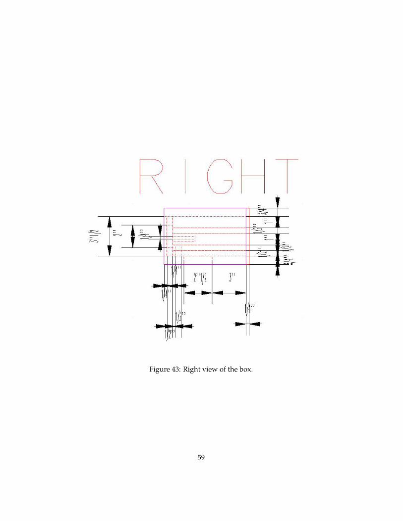
Figure 43: Right view of the box.
59

Figure 44: Right view of the box.
60