Technical Documentation: Instruction Manual for Hand-held ... · instruction manual and is specific...
44
Technical Documentation Microphone Type 4190 for Hand-held Analyzer Types 2250, 2250-L and 2270 Supplement to Instruction Manual BE 1712 English BE 1805 – 14
Transcript of Technical Documentation: Instruction Manual for Hand-held ... · instruction manual and is specific...
TechnicalDocumentation
Microphone Type 4190for Hand-held Analyzer Types 2250, 2250-L and 2270
Supplement to Instruction Manual BE 1712
HEADQUARTERS: Brüel & Kjær Sound & Vibration Measurement A/S · DK-2850 Nærum · DenmarkTelephone: +45 7741 2000 · Fax: +45 4580 1405 · www.bksv.com · [email protected]
Local representatives and service organisations worldwide
ËBE-1805---"Î
English BE 1805 – 14


BE 180514 March 2012
Microphone Type 4190for Hand-held Analyzer
Types 2250, 2250-L and 2270
Type 2250, from Hardware Version 1.1Type 2250-L, from Hardware Version 2.0Type 2270, from Hardware Version 3.0
Supplement to Instruction Manual BE 1712

Copyright 2008 – 2012, Brüel & Kjær Sound & Vibration Measurement A/S
All rights reserved. No part of this publication may be reproduced or distributed in any form, or by any means,without prior written consent from Brüel & Kjær Sound & Vibration Measurement A/S, Nærum, Denmark.
Safety ConsiderationsThis apparatus has been designed and tested in accordance with IEC 61010 – 1 and EN 61010 – 1 Safety Requirementsfor Electrical Equipment for Measurement, Control and Laboratory Use. This manual contains informationand warnings which must be followed to ensure safe operation and to retain the apparatus in safe condition. Specialnote should be made of the following:
Safety Symbols
The apparatus will be marked with this symbol when it is important that you refer to the associated warningstatements given in the manual.
Protective Earth Terminal Hazardous Voltage
Explosion Hazard
The equipment is not designed to be used in potentially explosive environments. It should not be operated in thepresence of flammable liquids or gases.
Warnings
• Switch off all power to equipment before connecting or disconnecting their digital interface. Failure to do socould damage the equipment.
• Whenever it is likely that the correct function or operating safety of the apparatus has been impaired, it mustbe made inoperative and be secured against unintended operation.
• Any adjustment, maintenance and repair of the open apparatus under voltage must be avoided as far as possibleand, if unavoidable, must be carried out only by trained service personnel.
• Do not dispose of electronic equipment as unsorted municipal waste• It is your responsibility to contribute to a clean and healthy environment by using the appropriate local
return and collection systems• Hazardous substances in electronic equipment may have detrimental effects on the environment and
human health• The symbol shown to the left indicates that separate collection systems must be used for any discarded
equipment marked with that symbol• Waste electrical and electronic equipment may be returned to your local Brüel & Kjær representative
or to Brüel & Kjær Headquarters for disposal

Table of Contents
CHAPTER 1Introduction.......................................................................................................................................... 1
1.1 About This Supplement ............................................................................................................................. 11.2 System Overview....................................................................................................................................... 1
CHAPTER 2Information Required by the Standards ............................................................................................ 3
2.1 Introduction................................................................................................................................................ 3
CHAPTER 3Conformance Testing.......................................................................................................................... 5
3.1 Introduction................................................................................................................................................ 5
CHAPTER 4Specifications ...................................................................................................................................... 7
4.1 Specifications ............................................................................................................................................ 74.5 Microphone................................................................................................................................................ 74.7 Directional Responses............................................................................................................................. 124.8 Self-generated Noise............................................................................................................................... 124.9 Measuring Ranges .................................................................................................................................. 164.11 Spectrum Analysis................................................................................................................................... 20
APPENDIX ATables ................................................................................................................................................. 21
A.2 Free-field Frequency Responses ............................................................................................................ 21A.3 Diffuse-field Frequency Responses......................................................................................................... 27A.4 Free-field Frequency Responses for Diffuse-field Calibrated Instruments .............................................. 31A.5 Directional Responses............................................................................................................................. 33A.6 Periodic Testing of Acoustical Frequency Responses ............................................................................ 33
INDEX ........................................................................................................................................................................... 35


1
Chapter 1Introduction
1.1 About This Supplement
This document is a supplement, to Instruction Manual for Hand-held Analyzer Types 2250, 2250-L and2270 BE 1712. It provides the information relevent when Hand-held Analyzer Type 2250, 2250 L or 2270is configured with Free-field ½ Condenser Microphone Type 4190.
The combination of Free-field ½ Condenser Microphone Type 4190 and the hand-held analyzer isintended for general purpose use.
The numbering of chapters, sections, figures and tables in this supplement corresponds toInstruction Manual BE 1712. This supplement only contains content that is different from theinstruction manual and is specific to this microphone configuration. The other chapters, sections,figures and tables should be read in Instruction Manual BE 1712.
Also see section 1.1 of the instruction manual.
1.2 System Overview
1.2.4 Hardware Setup
This section provides an overview of the additional hardware components used when the analyzers areconfigured with Microphone Type 4190. The other hardware components can be found in Instruction ManualBE 1712, section 1.2.4.
Table 1.1Additional hardware components needed for conformance testing of the analyzers configured with Type 4190
Quantity*Brüel & Kjær
Type/Part Number
Description
1 or 2 Type 4190 Free-field ½" Condenser Microphone
*. Quantity depends on which analyzer is to be tested.

Microphone Type 4190 – Supplement to Instruction Manual BE 17122

3
Chapter 2Information Required by the Standards
2.1 Introduction
This chapter contains detailed information required by the standards to be described in the InstructionManual.
No additional information is required in Chapter 2 when using Microphone Type 4190 togetherwith the analyzer.

Microphone Type 4190 – Supplement to Instruction Manual BE 17124

5
Chapter 3Conformance Testing
3.1 Introduction
This chapter contains the information needed to conduct conformance testing according to the specifiedstandards.
No additional information is required in Chapter 3 when using Microphone Type 4190 togetherwith the analyzer.

Microphone Type 4190 – Supplement to Instruction Manual BE 17126
7
Chapter 4Specifications
4.1 Specifications
Specifications are given for the configurations detailed in Chapter 1.
Unless specifically noted, specifications are given as typical data under Reference EnvironmentalConditions, and with the system calibrated to the nominal microphone open circuit sensitivity.
NOTE: The specifications given here for the Z-weighting, as defined in IEC 61672–1, are also valid forthe Lin response, as defined in IEC 60651.
4.5 Microphone
Microphone Type 4190 and Microphone Preamplifier ZC-0032:
Type: Free-field ½ Condenser Microphone
Polarization Voltage: 200 V
Nominal Open Circuit Sensitivity: 50 mV/Pa, (corresponding to –26 dB re 1 V/Pa) ± 1.5 dB
Capacitance: 16 pF (at 250 Hz)
Nominal Preamplifier Attenuation: 0.22 dB
Extension Cables between Microphone Preamplifier ZC-0032 and the analyzer: Up to 100 m withoutdegradation of the specifications. NOTE: EMC is only tested with a 10 m cable (AO-0697-D-100)
Microphone Reference Point: The centre of the front surface of the microphone protection grid.
Reference Direction of Sound Incidence: See the small drawings in the lower right corner of thedirectional response graphs in section 4.7.
4.6.2 Typical Low-frequency Responses
The typical Low-frequency Responses for Z-frequency weighting are given in Fig.4.2. For the rear‘Input’ socket Electrical Responses refer to section 4.6.2 in the Instruction Manual. The AcousticalResponses include Microphone Type 4190 and Microphone Preamplifier ZC-0032.
The Low-frequency Responses depends on the state of the Extended Low Frequency parameter on theSetup display, under Input.
The Low-frequency Responses are not influenced by the microphone accessories described in section 1.2.4.
The Low-frequency Responses for introduction of the electrical signal through the recommended means tosubstitute the microphone with an electrical input facility (see section 3.5) differs from the electricalresponses in Fig.4.2 in the Instruction Manual because it also includes Microphone Preamplifier ZC-0032.

Microphone Type 4190 – Supplement to Instruction Manual BE 17128
Fig.4.2 Typical low-frequency responses
4.6.5 Free-field Frequency Responses
The free-field frequency responses for plane progressive sinusoidal sound waves incident from thereference direction with Z-frequency weighting are provided in Fig.4.3 to Fig.4.8 and Table A.2 toTable A.6. The tables also provide the ‘Expanded Uncertainties of Measurement’ required byIEC 61672–1, see the start of section 4.6 in the Instruction Manual.
Fig.4.3 Free-field 0 frequency response for Microphone Type 4190, Microphone Preamplifier ZC-0032 and theanalyzer’s electrical response, with the Microphone Preamplifier connected to a microphone extension cable.Corresponds to the “Acoustical Response” column in Table A.2
-4
-2
0
2
4
dB
1 10 100 Hz
Acoustical Response with Type 4190, Extended Low Frequency 'On'
Acoustical Response with Type 4190, Extended Low Frequency 'Off'
080128/1
100 1000 10000 Hz-4
-2
0
2
4
dB
080129
CHAPTER 4Specifications 9
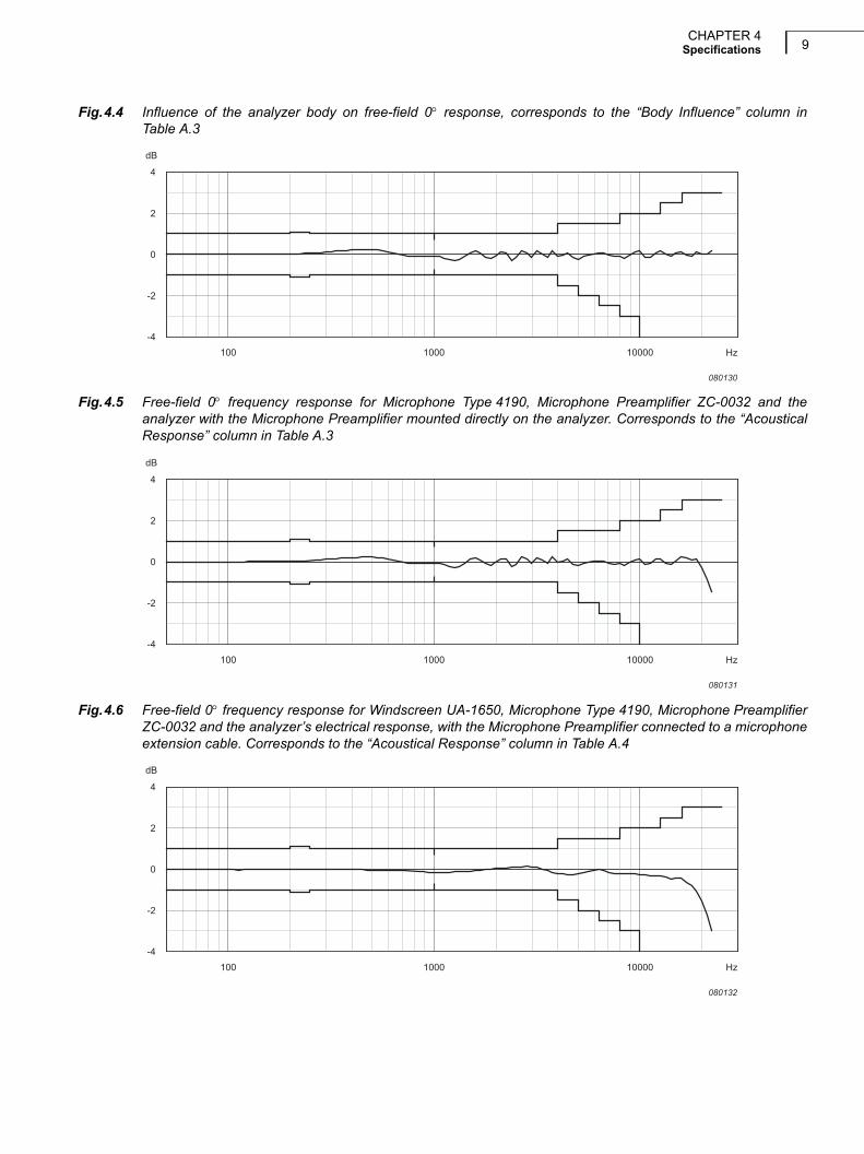
Fig.4.4 Influence of the analyzer body on free-field 0 response, corresponds to the “Body Influence” column inTable A.3
Fig.4.5 Free-field 0 frequency response for Microphone Type 4190, Microphone Preamplifier ZC-0032 and theanalyzer with the Microphone Preamplifier mounted directly on the analyzer. Corresponds to the “AcousticalResponse” column in Table A.3
Fig.4.6 Free-field 0 frequency response for Windscreen UA-1650, Microphone Type 4190, Microphone PreamplifierZC-0032 and the analyzer’s electrical response, with the Microphone Preamplifier connected to a microphoneextension cable. Corresponds to the “Acoustical Response” column in Table A.4
100 1000 10000 Hz-4
-2
0
2
4
dB
080130
100 1000 10000 Hz-4
-2
0
2
4
dB
080131
100 1000 10000 Hz-4
-2
0
2
4
dB
080132
Microphone Type 4190 – Supplement to Instruction Manual BE 171210
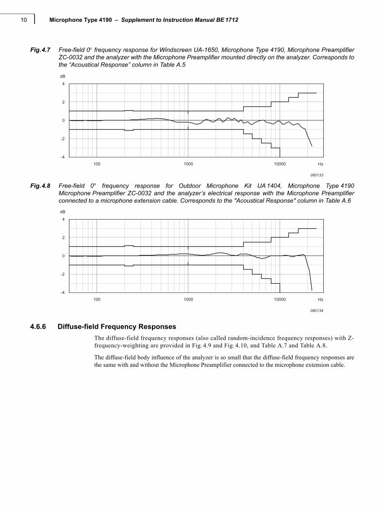
Fig.4.7 Free-field 0 frequency response for Windscreen UA-1650, Microphone Type 4190, Microphone PreamplifierZC-0032 and the analyzer with the Microphone Preamplifier mounted directly on the analyzer. Corresponds tothe “Acoustical Response” column in Table A.5
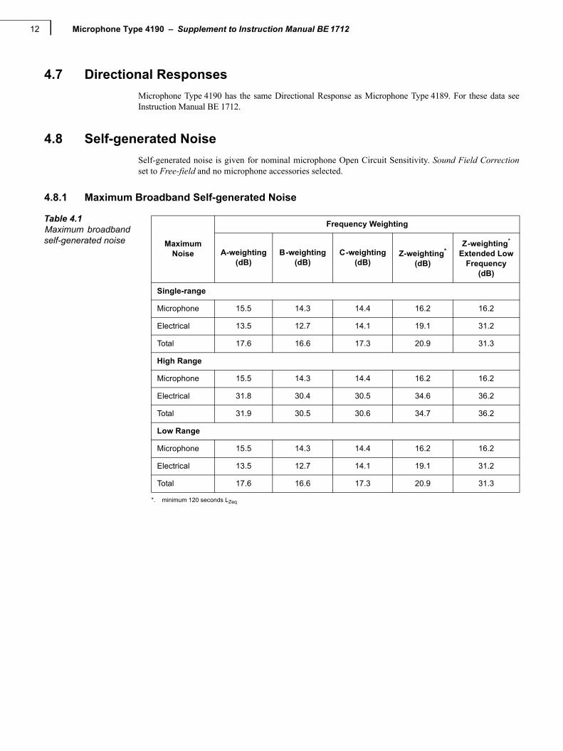
Fig.4.8 Free-field 0° frequency response for Outdoor Microphone Kit UA 1404, Microphone Type 4190Microphone Preamplifier ZC-0032 and the analyzer’s electrical response with the Microphone Preamplifierconnected to a microphone extension cable. Corresponds to the "Acoustical Response" column in Table A.6
4.6.6 Diffuse-field Frequency Responses
The diffuse-field frequency responses (also called random-incidence frequency responses) with Z-frequency-weighting are provided in Fig. 4.9 and Fig. 4.10, and Table A.7 and Table A.8.
The diffuse-field body influence of the analyzer is so small that the diffuse-field frequency responses arethe same with and without the Microphone Preamplifier connected to the microphone extension cable.
100 1000 10000 Hz-4
-2
0
2
4
dB
080133
100 1000 10000 Hz-4
-2
0
2
4
dB
080134

CHAPTER 4Specifications 11
Fig.4.9 Diffuse-field frequency response for Microphone Type 4190, Microphone Preamplifier ZC-0032 and theanalyzer with or without the Microphone Preamplifier connected to a microphone extension cable.Corresponds to the “Acoustical Response” column in Table A.7
Fig.4.10 Diffuse-field frequency response for Windscreen UA-1650, Microphone Type 4190, Microphone PreamplifierZC-0032 and the analyzer with or without the Microphone Preamplifier connected to a microphone extensioncable. Corresponds to the “Acoustical Response” column in Table A.8
Fig.4.11 Diffuse field frequency response for Outdoor Microphone Kit UA-1404, Microphone Type 4190 MicrophonePreamplifier ZC-0032 and the analyzer with the Microphone Preamplifier connected to a microphoneextension cable. Corresponds to the "Acoustical Response" column in Table A.9
100 1000 10000 Hz-4
-2
0
2
4
dB
080135
100 1000 10000 Hz-4
-2
0
2
4
dB
080136
100 1000 10000 Hz-4
-2
0
2
4
dB
080137
Microphone Type 4190 – Supplement to Instruction Manual BE 171212
4.7 Directional Responses
Microphone Type 4190 has the same Directional Response as Microphone Type 4189. For these data seeInstruction Manual BE 1712.
4.8 Self-generated Noise
Self-generated noise is given for nominal microphone Open Circuit Sensitivity. Sound Field Correctionset to Free-field and no microphone accessories selected.
4.8.1 Maximum Broadband Self-generated Noise
Table 4.1Maximum broadbandself-generated noise Maximum
Noise
Frequency Weighting
A-weighting(dB)
B-weighting(dB)
C-weighting(dB)
Z-weighting*
(dB)
*. minimum 120 seconds LZeq
Z-weighting*
Extended LowFrequency
(dB)
Single-range
Microphone 15.5 14.3 14.4 16.2 16.2
Electrical 13.5 12.7 14.1 19.1 31.2
Total 17.6 16.6 17.3 20.9 31.3
High Range
Microphone 15.5 14.3 14.4 16.2 16.2
Electrical 31.8 30.4 30.5 34.6 36.2
Total 31.9 30.5 30.6 34.7 36.2
Low Range
Microphone 15.5 14.3 14.4 16.2 16.2
Electrical 13.5 12.7 14.1 19.1 31.2
Total 17.6 16.6 17.3 20.9 31.3

CHAPTER 4Specifications 13
4.8.2 Typical Broadband Self-generated Noise
Table 4.2Typical broadbandself-generated noise
Typical Noise
Frequency Weighting
A-weighting(dB)
B-weighting(dB)
C-weighting(dB)
Z-weighting*
(dB)
*. minimum 120 seconds LZeq
Z-weighting*
Extended LowFrequency
(dB)
Single-range
Microphone 14.5 13.3 13.4 15.2 15.2
Electrical 12.3 11.4 12.7 17.8 26.3
Total 16.5 15.5 16.1 19.7 26.6
High Range
Microphone 14.5 13.3 13.4 15.2 15.2
Electrical 28.2 26.9 26.9 30.9 32.0
Total 28.4 27.1 27.1 31.0 32.1
Low Range
Microphone 14.5 13.3 13.4 15.2 15.2
Electrical 12.3 11.4 12.7 17.8 26.3
Total 16.5 15.5 16.1 19.7 26.6

Microphone Type 4190 – Supplement to Instruction Manual BE 171214
4.8.3 Typical Self-generated Noise Spectra
Typical spectra for self-generated noise are shown in Fig.4.24 to Fig.4.29.
Fig.4.24 Typical self-generated noise, 1/1 octave band, Single-range
Fig.4.25 Typical self-generated noise, 1/1-octave band, High Range
-20 dB
-15 dB
-10 dB
-5 dB
0 dB
5 dB
10 dB
15 dB
8 16 31.5 63 125 250 500 1 k 2 k 4 k 8 k 16 k
Microphone Electrical Total
080139
–20 dB
–15 dB
–10 dB
–5 dB
0 dB
5 dB
10 dB
15 dB
20 dB
25 dB
30 dB
8 16 31,5 63 125 250 500 1 k 2 k 4 k 8 k 16 k
Microphone Electrical Total
Frequency (Hz) 110090

CHAPTER 4Specifications 15
Fig.4.26 Typical self-generated noise, 1/1 octave band, Low Range
Fig.4.27 Typical self-generated noise, 1/3 octave band, Single-range
-20 dB
-15 dB
-10 dB
-5 dB
0 dB
5 dB
10 dB
15 dB
8 16 31,5 63 125 250 500 1 k 2 k 4 k 8 k 16 k
Microphone Electrical Total
090037
-20 dB
-15 dB
-10 dB
-5 dB
0 dB
5 dB
10 dB
15 dB
6.3 8 10
12.5 16 20 25
31.5 40 50 63 80 100
125
160
200
250
315
400
500
630
800
1 k
1.25
k
1.6
k
2 k
2.5
k
3.15
k 4 k
5 k
6.3
k
8 k
10 k
12.5
k
16 k
20 k
Microphone Electrical Total
080140

Microphone Type 4190 – Supplement to Instruction Manual BE 171216
Fig.4.28 Typical self-generated noise, 1/3-octave band, High Range
Fig.4.29 Typical self-generated noise, 1/3 octave band, Low Range
4.9 Measuring Ranges
The Upper Limit in the following sections is based on the guaranteed worst-case limit for the analyzer andthe nominal Open Circuit Sensitivity of the microphone. The Overload Limit can, due to tolerances in theanalyzer, be up to 1.5 dB higher than the worst-case limit, but tolerances specified in the InternationalStandards are maintained as long as no Overload is indicated.
The Lower Limit in the following sections is based on the guaranteed worst-case limit for the analyzer andthe nominal Open Circuit Sensitivity of the microphone, under Reference Environmental Conditions, SoundField Correction set to Free-field and no microphone accessories selected.
Microphone Electrical Total
110089
–20 dB
–15 dB
–10 dB
–5 dB
0 dB
5 dB
10 dB
15 dB
20 dB
25 dB
30 dB
6.3 8 10
12.5 16 20 25
31.5 40 50 63 80 100
125
160
200
250
315
400
500
630
800
1 k
1.25
k
1.6
k
2 k
2.5
k
3.15
k 4 k
5 k
6.3
k
8 k
10 k
12.5
k
16 k
20 k
-20 dB
-15 dB
-10 dB
-5 dB
0 dB
5 dB
10 dB
15 dB
6.3 8 10
12.5 16 20 25
31.5 40 50 63 80 100
125
160
200
250
315
400
500
630
800
1 k
1.25
k
1.6
k
2 k
2.5
k
3.15
k 4 k
5 k
6.3
k
8 k
10 k
12.5
k
16 k
20 k
Microphone Electrical Total
090038
CHAPTER 4Specifications 17
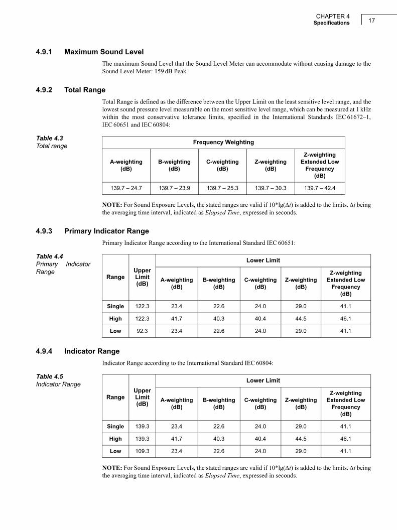
4.9.1 Maximum Sound Level
The maximum Sound Level that the Sound Level Meter can accommodate without causing damage to theSound Level Meter: 159 dB Peak.
4.9.2 Total Range
Total Range is defined as the difference between the Upper Limit on the least sensitive level range, and thelowest sound pressure level measurable on the most sensitive level range, which can be measured at 1 kHzwithin the most conservative tolerance limits, specified in the International Standards IEC 61672–1,IEC 60651 and IEC 60804:
NOTE: For Sound Exposure Levels, the stated ranges are valid if 10*lg(t) is added to the limits. t beingthe averaging time interval, indicated as Elapsed Time, expressed in seconds.
4.9.3 Primary Indicator Range
Primary Indicator Range according to the International Standard IEC 60651:
4.9.4 Indicator Range
Indicator Range according to the International Standard IEC 60804:
NOTE: For Sound Exposure Levels, the stated ranges are valid if 10*lg(t) is added to the limits. t beingthe averaging time interval, indicated as Elapsed Time, expressed in seconds.
Table 4.3Total range
Frequency Weighting
A-weighting(dB)
B-weighting(dB)
C-weighting(dB)
Z-weighting (dB)
Z-weightingExtended Low
Frequency(dB)
139.7 – 24.7 139.7 – 23.9 139.7 – 25.3 139.7 – 30.3 139.7 – 42.4
Table 4.4Primary IndicatorRange
RangeUpperLimit(dB)
Lower Limit
A-weighting(dB)
B-weighting(dB)
C-weighting(dB)
Z-weighting(dB)
Z-weightingExtended Low
Frequency(dB)
Single 122.3 23.4 22.6 24.0 29.0 41.1
High 122.3 41.7 40.3 40.4 44.5 46.1
Low 92.3 23.4 22.6 24.0 29.0 41.1
Table 4.5Indicator Range
RangeUpperLimit(dB)
Lower Limit
A-weighting(dB)
B-weighting(dB)
C-weighting(dB)
Z-weighting(dB)
Z-weightingExtended Low
Frequency(dB)
Single 139.3 23.4 22.6 24.0 29.0 41.1
High 139.3 41.7 40.3 40.4 44.5 46.1
Low 109.3 23.4 22.6 24.0 29.0 41.1

Microphone Type 4190 – Supplement to Instruction Manual BE 171218
4.9.5 Linearity Range
Linearity Range according to the International Standard IEC 60804 is the difference between the Upperand Lower Limit in the following table:
NOTE: For Sound Exposure Levels, the stated ranges are valid if 10*lg(t) is added to the limits. t beingthe averaging time interval, indicated as Elapsed Time, expressed in seconds.
4.9.6 Pulse Range
Pulse Range according to the International Standard IEC 60804 is the difference between the Upper andLower Limit in the following table:
NOTE: For Sound Exposure Levels, the stated ranges are valid if 10*lg(t) is added to the limits. t beingthe averaging time interval, indicated as Elapsed Time, expressed in seconds.
4.9.7 Linear Operating Range
The starting point for all the Linear Operating Range tests is 94.0 dB.
Linear Operating Range according to the International Standard IEC 61672–1:
Table 4.6Linearity Range
RangeUpperLimit(dB)
Lower Limit
A-weighting(dB)
B-weighting(dB)
C-weighting(dB)
Z-weighting(dB)
Z-weightingExtended Low
Frequency(dB)
Single 140.7 21.3 20.5 21.9 26.9 39.0
High 140.7 39.6 38.2 38.3 42.4 44.0
Low 110.7 21.3 20.5 21.9 26.9 39.0
Table 4.7Pulse Range
RangeUpperLimit(dB)
Lower Limit
A-weighting(dB)
B-weighting(dB)
C-weighting(dB)
Z-weighting(dB)
Z-weightingExtended Low
Frequency(dB)
Single 143.7 21.3 20.5 21.9 26.9 39.0
High 143.7 39.6 38.2 38.3 42.4 44.0
Low 113.7 21.3 20.5 21.9 26.9 39.0
Table 4.8Linear Operating Range Frequency-
Weighting
Upper LimitLowerLimit
31.5 Hz(dB)
1 kHz(dB)
4 kHz(dB)
8 kHz(dB)
12.5 kHz(dB)
All(dB)
Single-range
A-weighting 100.6 139.7 140.7 139.0 135.3 24.7
B-weighting 122.9 139.7 139.0 137.2 133.5 23.9
C-weighting 137.0 139.7 138.9 137.1 133.4 25.3

CHAPTER 4Specifications 19
NOTE: For Sound Exposure Levels, the stated ranges are valid if 10*lg(t) is added to the limits. t beingthe averaging time interval, indicated as Elapsed Time, expressed in seconds.
4.9.8 Peak C Range
Peak C Range according to the International Standard IEC 61672–1 is:
Z-weighting 140.0 139.7 139.7 140.1 139.6 30.3
Z-weightingExtended Low
Frequency140.0 139.7 139.7 140.1 139.6 42.4
High Range
A-weighting 100.6 139.7 140.7 139.0 135.3 43.0
B-weighting 122.9 139.7 139.0 137.2 133.5 41.6
C-weighting 137.0 139.7 138.9 137.1 133.4 41.7
Z-weighting 140.0 139.7 139.7 140.1 139.6 45.8
Z-weightingExtended Low
Frequency140.0 139.7 139.7 140.1 139.6 47.4
Low Range
A-weighting 70.6 109.7 110.7 109.0 105.3 24.7
B-weighting 92.9 109.7 109.0 107.2 103.5 23.9
C-weighting 107.0 109.7 108.9 107.1 103.4 25.3
Z-weighting 110.0 109.7 109.7 110.1 109.6 30.3
Z-weightingExtended Low
Frequency110.0 109.7 109.7 110.1 109.6 42.4
Table 4.8Linear Operating Range (Continued) Frequency-
Weighting
Upper LimitLowerLimit
31.5 Hz(dB)
1 kHz(dB)
4 kHz(dB)
8 kHz(dB)
12.5 kHz(dB)
All(dB)
Table 4.9Peak C Range
Range
Upper LimitLower Limit
31.5 Hz(dB)
1 kHz(dB)
4 kHz(dB)
8 kHz(dB)
12.5 kHz(dB)
All(dB)
Single 140.0 142.7 141.9 140.1 136.4 42.1
High 140.0 142.7 141.9 140.1 136.4 58.5
Low 110.0 112.7 111.9 110.1 106.4 42.1

Microphone Type 4190 – Supplement to Instruction Manual BE 171220
4.11 Spectrum Analysis
4.11.3 Linear Operating Range
Linear Operating Range according to the International Standard IEC 61260, for electrical input, for allfilters in the filter banks:
:
Below the Lower Limit, the Level Linearity Error is less than or equal to the error found in Fig.2.1 withLinh set to the Lower Limit – 11.5 dB.
4.11.4 Measurement Range
Measurement Range according to the International Standard IEC 61260 is the difference between theUpper Limit of the Linear Operating Range on the least sensitive level range and the Lower Limit of theLinear Operating Range on the most sensitive level range.
Table 4.11Linear Operating Range
RangeUpper Limit
(dB)Lower Limit 1/1-octave
(dB)Lower Limit 1/3-octave
(dB
Single 140.0 24.1 20.2
High 140.0 43.0 39.3
Low 110.0 24.1 20.2
Table 4.12MeasurementRange
1/1-octave(dB)
1/3-octave(dB)
140.0 – 24.1 140.0 – 20.2

21
Appendix ATables
A.2 Free-field Frequency Responses
Frequency responses with Z-frequency-weighting. Measured with plane progressive sinusoidal soundwaves incident from the reference direction and the instrument’s Sound Field Correction parameter set toFree-field, see section 4.6.5.
Table A.2 Free-field 0 frequency response for Microphone Type 4190, Microphone Preamplifier ZC-0032 and theanalyzer’s electrical response with the Microphone Preamplifier connected to a microphone extension cable
Nominal Exact Microphone Microphone Microphone Electrical Acoustical ExpandedFrequency Frequency Actuator Free-field Free-field Response Response Uncertainty
(6 digits) Response Correction ResponseHz Hz dB dB dB dB dB dB
63 63.0957 –0.02 0.00 –0.02 0.00 –0.02 0.0580 79.4328 –0.02 0.00 –0.02 0.00 –0.02 0.05
100 100 –0.03 0.00 –0.03 0.00 –0.03 0.05125 125.893 0.01 0.00 0.01 0.00 0.01 0.05160 158.489 0.01 0.00 0.01 0.00 0.01 0.05
200 199.526 0.01 0.00 0.01 0.00 0.01 0.05250 251.189 0.00 0.00 0.00 0.00 0.00 0.05315 316.228 –0.01 0.01 0.00 0.00 0.00 0.06
400 398.107 –0.02 0.01 –0.01 0.00 –0.01 0.06500 501.187 –0.03 0.02 –0.01 0.00 –0.01 0.07630 630.957 –0.04 0.04 0.00 0.00 0.00 0.07
800 794.328 –0.06 0.07 0.01 0.00 0.01 0.071000 1000 –0.09 0.10 0.01 0.00 0.01 0.071060 1059.25 –0.10 0.11 0.02 0.00 0.02 0.071120 1122.02 –0.11 0.12 0.02 0.00 0.02 0.07
1180 1188.5 –0.12 0.14 0.02 0.00 0.02 0.081250 1258.93 –0.13 0.15 0.02 0.00 0.02 0.081320 1333.52 –0.14 0.17 0.03 0.00 0.03 0.081400 1412.54 –0.16 0.18 0.03 0.00 0.03 0.08
1500 1496.24 –0.17 0.20 0.03 0.00 0.03 0.081600 1584.89 –0.19 0.22 0.03 0.00 0.03 0.081700 1678.8 –0.21 0.24 0.03 0.00 0.03 0.081800 1778.28 –0.23 0.27 0.03 0.00 0.03 0.09
1900 1883.65 –0.26 0.29 0.04 0.00 0.04 0.092000 1995.26 –0.29 0.32 0.04 0.00 0.04 0.092120 2113.49 –0.32 0.36 0.04 0.00 0.04 0.092240 2238.72 –0.35 0.39 0.04 0.00 0.04 0.09
2360 2371.37 –0.39 0.43 0.04 0.01 0.05 0.102500 2511.89 –0.44 0.48 0.04 0.01 0.05 0.102650 2660.73 –0.49 0.53 0.04 0.01 0.05 0.102800 2818.38 –0.54 0.59 0.04 0.01 0.05 0.11
3000 2985.38 –0.60 0.65 0.04 0.01 0.05 0.113150 3162.28 –0.67 0.71 0.04 0.01 0.05 0.123350 3349.65 –0.75 0.78 0.04 0.01 0.05 0.123550 3548.13 –0.83 0.86 0.03 0.01 0.04 0.13

Microphone Type 4190 – Supplement to Instruction Manual BE 171222
Nominal Exact Microphone Microphone Microphone Electrical Acoustical ExpandedFrequency Frequency Actuator Free-field Free-field Response Response Uncertainty
(6 digits) Response Correction ResponseHz Hz dB dB dB dB dB dB
3750 3758.37 –0.92 0.96 0.04 0.01 0.05 0.134000 3981.07 –1.03 1.07 0.04 0.01 0.05 0.144250 4216.97 –1.14 1.18 0.04 0.01 0.05 0.144500 4466.84 –1.27 1.30 0.03 0.01 0.04 0.14
4750 4731.51 –1.40 1.43 0.03 0.02 0.05 0.145000 5011.87 –1.56 1.57 0.02 0.02 0.04 0.155300 5308.84 –1.72 1.73 0.01 0.02 0.03 0.155600 5623.41 –1.91 1.90 –0.01 0.02 0.01 0.15
6000 5956.62 –2.11 2.09 –0.02 0.02 0.00 0.166300 6309.57 –2.32 2.28 –0.04 0.02 –0.02 0.166700 6683.44 –2.56 2.49 –0.07 0.03 –0.04 0.177100 7079.46 –2.82 2.74 –0.08 0.03 –0.05 0.17
7500 7498.94 –3.11 3.04 –0.07 0.03 –0.04 0.178000 7943.28 –3.42 3.38 –0.03 0.03 0.00 0.188500 8413.95 –3.77 3.75 –0.02 0.02 0.00 0.199000 8912.51 –4.17 4.14 –0.03 0.01 –0.02 0.20
9500 9440.61 –4.62 4.60 –0.02 –0.01 –0.03 0.2210000 10000 –5.10 5.12 0.02 –0.04 –0.02 0.2310600 10592.5 –5.59 5.68 0.10 –0.09 0.01 0.2411200 11220.2 –6.05 6.27 0.22 –0.17 0.05 0.26
11800 11885 –6.46 6.81 0.35 –0.27 0.08 0.2812500 12589.3 –6.80 7.19 0.40 –0.40 0.00 0.2913200 13335.2 –7.08 7.54 0.46 –0.52 –0.06 0.3114000 14125.4 –7.33 7.89 0.56 –0.63 –0.07 0.33
15000 14962.4 –7.54 8.24 0.70 –0.70 0.00 0.3516000 15848.9 –7.74 8.59 0.85 –0.73 0.12 0.3817000 16788 –8.01 8.91 0.90 –0.73 0.17 0.4018000 17782.8 –8.39 9.27 0.87 –0.71 0.16 0.43
19000 18836.5 –8.93 9.62 0.69 –0.70 –0.01 0.4520000 19952.6 –9.68 10.05 0.37 –0.68 –0.31 0.4821200 21134.9 –10.66 10.46 –0.21 –0.68 –0.89 0.4922400 22387.2 –11.77 10.85 –0.92 –0.70 –1.62 0.49
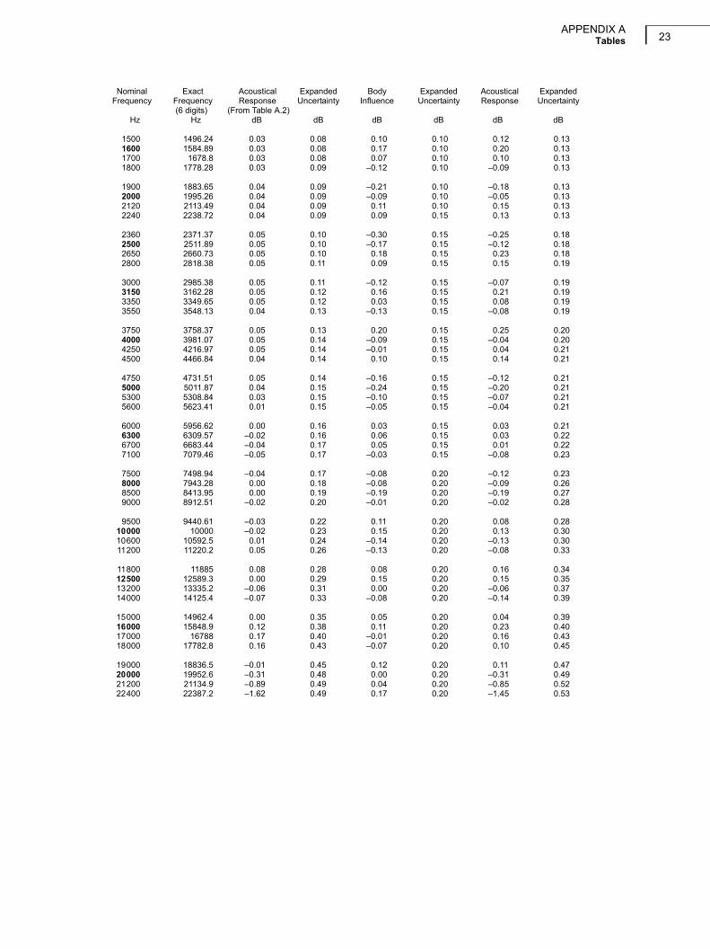
Table A.3 Free-field 0 frequency response for Microphone Type 4190, Microphone Preamplifier ZC-0032 and theanalyzer with the Microphone Preamplifier mounted directly on the analyzer
Nominal Exact Acoustical Expanded Body Expanded Acoustical ExpandedFrequency Frequency Response Uncertainty Influence Uncertainty Response Uncertainty
(6 digits) (From Table A.2)Hz Hz dB dB dB dB dB dB
63 63.0957 –0.02 0.05 0.00 0.10 –0.02 0.1180 79.4328 –0.02 0.05 0.00 0.10 –0.02 0.11
100 100 –0.03 0.05 0.00 0.10 –0.03 0.11125 125.893 0.01 0.05 0.00 0.10 0.01 0.11160 158.489 0.01 0.05 0.01 0.10 0.02 0.11
200 199.526 0.01 0.05 0.03 0.10 0.03 0.11250 251.189 0.00 0.05 0.07 0.10 0.07 0.11315 316.228 0.00 0.06 0.13 0.10 0.13 0.12
400 398.107 –0.01 0.06 0.21 0.10 0.20 0.12500 501.187 –0.01 0.07 0.22 0.10 0.22 0.12630 630.957 0.00 0.07 0.07 0.10 0.07 0.12
800 794.328 0.01 0.07 –0.11 0.10 –0.11 0.121000 1000 0.01 0.07 –0.07 0.10 –0.06 0.121060 1059.25 0.02 0.07 –0.10 0.10 –0.09 0.121120 1122.02 0.02 0.07 –0.18 0.10 –0.16 0.12
1180 1188.5 0.02 0.08 –0.26 0.10 –0.24 0.131250 1258.93 0.02 0.08 –0.30 0.10 –0.28 0.131320 1333.52 0.03 0.08 –0.24 0.10 –0.22 0.131400 1412.54 0.03 0.08 –0.08 0.10 –0.06 0.13
APPENDIX ATables 23
Nominal Exact Acoustical Expanded Body Expanded Acoustical ExpandedFrequency Frequency Response Uncertainty Influence Uncertainty Response Uncertainty
(6 digits) (From Table A.2)Hz Hz dB dB dB dB dB dB
1500 1496.24 0.03 0.08 0.10 0.10 0.12 0.131600 1584.89 0.03 0.08 0.17 0.10 0.20 0.131700 1678.8 0.03 0.08 0.07 0.10 0.10 0.131800 1778.28 0.03 0.09 –0.12 0.10 –0.09 0.13
1900 1883.65 0.04 0.09 –0.21 0.10 –0.18 0.132000 1995.26 0.04 0.09 –0.09 0.10 –0.05 0.132120 2113.49 0.04 0.09 0.11 0.10 0.15 0.132240 2238.72 0.04 0.09 0.09 0.15 0.13 0.13
2360 2371.37 0.05 0.10 –0.30 0.15 –0.25 0.182500 2511.89 0.05 0.10 –0.17 0.15 –0.12 0.182650 2660.73 0.05 0.10 0.18 0.15 0.23 0.182800 2818.38 0.05 0.11 0.09 0.15 0.15 0.19
3000 2985.38 0.05 0.11 –0.12 0.15 –0.07 0.193150 3162.28 0.05 0.12 0.16 0.15 0.21 0.193350 3349.65 0.05 0.12 0.03 0.15 0.08 0.193550 3548.13 0.04 0.13 –0.13 0.15 –0.08 0.19
3750 3758.37 0.05 0.13 0.20 0.15 0.25 0.204000 3981.07 0.05 0.14 –0.09 0.15 –0.04 0.204250 4216.97 0.05 0.14 –0.01 0.15 0.04 0.214500 4466.84 0.04 0.14 0.10 0.15 0.14 0.21
4750 4731.51 0.05 0.14 –0.16 0.15 –0.12 0.215000 5011.87 0.04 0.15 –0.24 0.15 –0.20 0.215300 5308.84 0.03 0.15 –0.10 0.15 –0.07 0.215600 5623.41 0.01 0.15 –0.05 0.15 –0.04 0.21
6000 5956.62 0.00 0.16 0.03 0.15 0.03 0.216300 6309.57 –0.02 0.16 0.06 0.15 0.03 0.226700 6683.44 –0.04 0.17 0.05 0.15 0.01 0.227100 7079.46 –0.05 0.17 –0.03 0.15 –0.08 0.23
7500 7498.94 –0.04 0.17 –0.08 0.20 –0.12 0.238000 7943.28 0.00 0.18 –0.08 0.20 –0.09 0.268500 8413.95 0.00 0.19 –0.19 0.20 –0.19 0.279000 8912.51 –0.02 0.20 –0.01 0.20 –0.02 0.28
9500 9440.61 –0.03 0.22 0.11 0.20 0.08 0.2810000 10000 –0.02 0.23 0.15 0.20 0.13 0.3010600 10592.5 0.01 0.24 –0.14 0.20 –0.13 0.3011200 11220.2 0.05 0.26 –0.13 0.20 –0.08 0.33
11800 11885 0.08 0.28 0.08 0.20 0.16 0.3412500 12589.3 0.00 0.29 0.15 0.20 0.15 0.3513200 13335.2 –0.06 0.31 0.00 0.20 –0.06 0.3714000 14125.4 –0.07 0.33 –0.08 0.20 –0.14 0.39
15000 14962.4 0.00 0.35 0.05 0.20 0.04 0.3916000 15848.9 0.12 0.38 0.11 0.20 0.23 0.4017000 16788 0.17 0.40 –0.01 0.20 0.16 0.4318000 17782.8 0.16 0.43 –0.07 0.20 0.10 0.45
19000 18836.5 –0.01 0.45 0.12 0.20 0.11 0.4720000 19952.6 –0.31 0.48 0.00 0.20 –0.31 0.4921200 21134.9 –0.89 0.49 0.04 0.20 –0.85 0.5222400 22387.2 –1.62 0.49 0.17 0.20 –1.45 0.53
Microphone Type 4190 – Supplement to Instruction Manual BE 171224
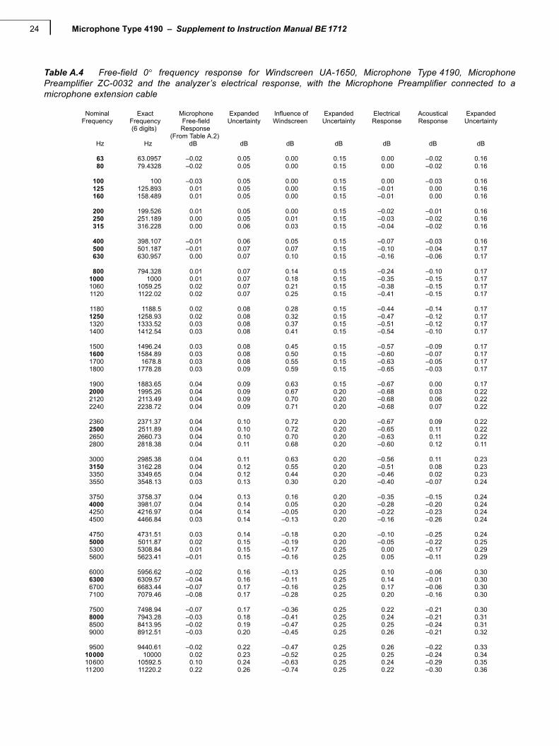
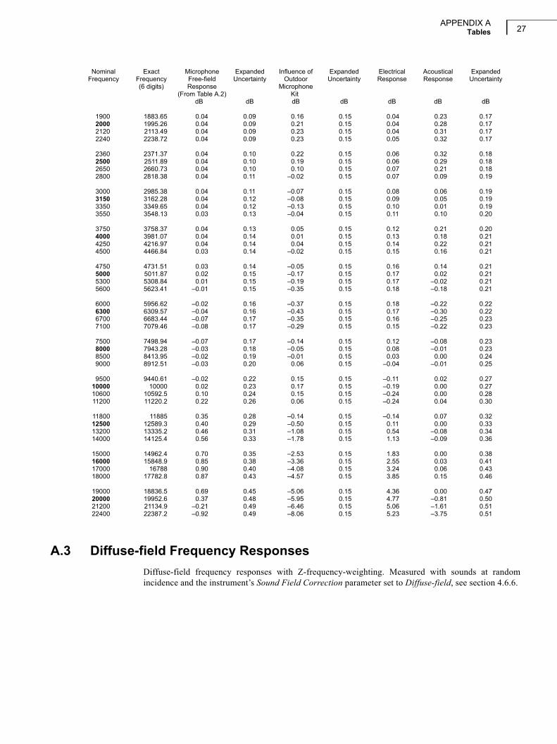
Table A.4 Free-field 0 frequency response for Windscreen UA-1650, Microphone Type 4190, MicrophonePreamplifier ZC-0032 and the analyzer’s electrical response, with the Microphone Preamplifier connected to amicrophone extension cable
Nominal Exact Microphone Expanded Influence of Expanded Electrical Acoustical ExpandedFrequency Frequency Free-field Uncertainty Windscreen Uncertainty Response Response Uncertainty
(6 digits) Response(From Table A.2)
Hz Hz dB dB dB dB dB dB dB
63 63.0957 –0.02 0.05 0.00 0.15 0.00 –0.02 0.1680 79.4328 –0.02 0.05 0.00 0.15 0.00 –0.02 0.16
100 100 –0.03 0.05 0.00 0.15 0.00 –0.03 0.16125 125.893 0.01 0.05 0.00 0.15 –0.01 0.00 0.16160 158.489 0.01 0.05 0.00 0.15 –0.01 0.00 0.16
200 199.526 0.01 0.05 0.00 0.15 –0.02 –0.01 0.16250 251.189 0.00 0.05 0.01 0.15 –0.03 –0.02 0.16315 316.228 0.00 0.06 0.03 0.15 –0.04 –0.02 0.16
400 398.107 –0.01 0.06 0.05 0.15 –0.07 –0.03 0.16500 501.187 –0.01 0.07 0.07 0.15 –0.10 –0.04 0.17630 630.957 0.00 0.07 0.10 0.15 –0.16 –0.06 0.17
800 794.328 0.01 0.07 0.14 0.15 –0.24 –0.10 0.171000 1000 0.01 0.07 0.18 0.15 –0.35 –0.15 0.171060 1059.25 0.02 0.07 0.21 0.15 –0.38 –0.15 0.171120 1122.02 0.02 0.07 0.25 0.15 –0.41 –0.15 0.17
1180 1188.5 0.02 0.08 0.28 0.15 –0.44 –0.14 0.171250 1258.93 0.02 0.08 0.32 0.15 –0.47 –0.12 0.171320 1333.52 0.03 0.08 0.37 0.15 –0.51 –0.12 0.171400 1412.54 0.03 0.08 0.41 0.15 –0.54 –0.10 0.17
1500 1496.24 0.03 0.08 0.45 0.15 –0.57 –0.09 0.171600 1584.89 0.03 0.08 0.50 0.15 –0.60 –0.07 0.171700 1678.8 0.03 0.08 0.55 0.15 –0.63 –0.05 0.171800 1778.28 0.03 0.09 0.59 0.15 –0.65 –0.03 0.17
1900 1883.65 0.04 0.09 0.63 0.15 –0.67 0.00 0.172000 1995.26 0.04 0.09 0.67 0.20 –0.68 0.03 0.222120 2113.49 0.04 0.09 0.70 0.20 –0.68 0.06 0.222240 2238.72 0.04 0.09 0.71 0.20 –0.68 0.07 0.22
2360 2371.37 0.04 0.10 0.72 0.20 –0.67 0.09 0.222500 2511.89 0.04 0.10 0.72 0.20 –0.65 0.11 0.222650 2660.73 0.04 0.10 0.70 0.20 –0.63 0.11 0.222800 2818.38 0.04 0.11 0.68 0.20 –0.60 0.12 0.11
3000 2985.38 0.04 0.11 0.63 0.20 –0.56 0.11 0.233150 3162.28 0.04 0.12 0.55 0.20 –0.51 0.08 0.233350 3349.65 0.04 0.12 0.44 0.20 –0.46 0.02 0.233550 3548.13 0.03 0.13 0.30 0.20 –0.40 –0.07 0.24
3750 3758.37 0.04 0.13 0.16 0.20 –0.35 –0.15 0.244000 3981.07 0.04 0.14 0.05 0.20 –0.28 –0.20 0.244250 4216.97 0.04 0.14 –0.05 0.20 –0.22 –0.23 0.244500 4466.84 0.03 0.14 –0.13 0.20 –0.16 –0.26 0.24
4750 4731.51 0.03 0.14 –0.18 0.20 –0.10 –0.25 0.245000 5011.87 0.02 0.15 –0.19 0.20 –0.05 –0.22 0.255300 5308.84 0.01 0.15 –0.17 0.25 0.00 –0.17 0.295600 5623.41 –0.01 0.15 –0.16 0.25 0.05 –0.11 0.29
6000 5956.62 –0.02 0.16 –0.13 0.25 0.10 –0.06 0.306300 6309.57 –0.04 0.16 –0.11 0.25 0.14 –0.01 0.306700 6683.44 –0.07 0.17 –0.16 0.25 0.17 –0.06 0.307100 7079.46 –0.08 0.17 –0.28 0.25 0.20 –0.16 0.30
7500 7498.94 –0.07 0.17 –0.36 0.25 0.22 –0.21 0.308000 7943.28 –0.03 0.18 –0.41 0.25 0.24 –0.21 0.318500 8413.95 –0.02 0.19 –0.47 0.25 0.25 –0.24 0.319000 8912.51 –0.03 0.20 –0.45 0.25 0.26 –0.21 0.32
9500 9440.61 –0.02 0.22 –0.47 0.25 0.26 –0.22 0.3310000 10000 0.02 0.23 –0.52 0.25 0.25 –0.24 0.3410600 10592.5 0.10 0.24 –0.63 0.25 0.24 –0.29 0.3511200 11220.2 0.22 0.26 –0.74 0.25 0.22 –0.30 0.36

APPENDIX ATables 25
Nominal Exact Microphone Expanded Influence of Expanded Electrical Acoustical ExpandedFrequency Frequency Free–field Uncertainty Windscreen Uncertainty Response Response Uncertainty
(6 digits) Response(From Table A.2)
Hz Hz dB dB dB dB dB dB dB
11800 11885 0.35 0.28 –0.86 0.25 0.20 –0.31 0.3812500 12589.3 0.40 0.29 –0.88 0.25 0.17 –0.32 0.3813200 13335.2 0.46 0.31 –0.99 0.25 0.14 –0.40 0.4014000 14125.4 0.56 0.33 –1.13 0.25 0.11 –0.46 0.41
15000 14962.4 0.70 0.35 –1.20 0.30 0.07 –0.44 0.4616000 15848.9 0.85 0.38 –1.33 0.30 0.03 –0.45 0.4817000 16788 0.90 0.40 –1.50 0.30 –0.02 –0.62 0.5018000 17782.8 0.87 0.43 –1.61 0.30 –0.07 –0.81 0.52
19000 18836.5 0.69 0.45 –1.64 0.30 –0.11 –1.06 0.5420000 19952.6 0.37 0.48 –1.73 0.30 –0.16 –1.52 0.5721200 21134.9 –0.21 0.49 –1.81 0.30 –0.21 –2.22 0.5722400 22387.2 –0.92 0.49 –1.79 0.30 –0.27 –2.98 0.57
Table A.5 Free-field 0 frequency response for Windscreen UA-1650, Microphone Type 4190, MicrophonePreamplifier ZC-0032 and the analyzer with the Microphone Preamplifier mounted directly on the analyzer
Nominal Exact Acoustical Expanded Body Expanded Acoustical ExpandedFrequency Frequency Response Uncertainty Influence Uncertainty Response Uncertainty
(6 digits) (From Table A.4)dB dB dB dB dB dB
63 63.0957 –0.02 0.16 0.00 0.10 –0.02 0.1980 79.4328 –0.02 0.16 0.00 0.10 –0.02 0.19
100 100 –0.03 0.16 0.00 0.10 –0.03 0.19125 125.893 0.00 0.16 0.00 0.10 0.00 0.19160 158.489 0.00 0.16 0.01 0.10 0.01 0.19
200 199.526 –0.01 0.16 0.03 0.10 0.01 0.19250 251.189 –0.02 0.16 0.07 0.10 0.05 0.19315 316.228 –0.02 0.16 0.13 0.10 0.11 0.19
400 398.107 –0.03 0.16 0.21 0.10 0.18 0.19500 501.187 –0.04 0.17 0.22 0.10 0.19 0.19630 630.957 –0.06 0.17 0.07 0.10 0.01 0.19
800 794.328 –0.10 0.17 –0.11 0.10 –0.21 0.191000 1000 –0.15 0.17 –0.07 0.10 –0.23 0.191060 1059.25 –0.15 0.17 –0.10 0.10 –0.25 0.191120 1122.02 –0.15 0.17 –0.18 0.10 –0.32 0.19
1180 1188.5 –0.14 0.17 –0.26 0.10 –0.39 0.201250 1258.93 –0.12 0.17 –0.30 0.10 –0.43 0.201320 1333.52 –0.12 0.17 –0.24 0.10 –0.36 0.201400 1412.54 –0.10 0.17 –0.08 0.10 –0.19 0.20
1500 1496.24 –0.09 0.17 0.10 0.10 0.01 0.201600 1584.89 –0.07 0.17 0.17 0.10 0.10 0.201700 1678.8 –0.05 0.17 0.07 0.10 0.02 0.201800 1778.28 –0.03 0.17 –0.12 0.10 –0.15 0.20
1900 1883.65 0.00 0.17 –0.21 0.10 –0.22 0.202000 1995.26 0.03 0.22 –0.09 0.10 –0.06 0.242120 2113.49 0.06 0.22 0.11 0.10 0.17 0.242240 2238.72 0.07 0.22 0.09 0.15 0.16 0.27
2360 2371.37 0.09 0.22 –0.30 0.15 –0.21 0.272500 2511.89 0.11 0.22 –0.17 0.15 –0.06 0.272650 2660.73 0.11 0.22 0.18 0.15 0.30 0.272800 2818.38 0.12 0.11 0.09 0.15 0.22 0.19
3000 2985.38 0.11 0.23 –0.12 0.15 –0.01 0.273150 3162.28 0.08 0.23 0.16 0.15 0.24 0.283350 3349.65 0.02 0.23 0.03 0.15 0.05 0.283550 3548.13 –0.07 0.24 –0.13 0.15 –0.19 0.28
3750 3758.37 –0.15 0.24 0.20 0.15 0.05 0.284000 3981.07 –0.20 0.24 –0.09 0.15 –0.29 0.294250 4216.97 –0.23 0.24 –0.01 0.15 –0.24 0.294500 4466.84 –0.26 0.24 0.10 0.15 –0.16 0.29

Microphone Type 4190 – Supplement to Instruction Manual BE 171226
Nominal Exact Acoustical Expanded Body Expanded Acoustical ExpandedFrequency Frequency Response Uncertainty Influence Uncertainty Response Uncertainty
(6 digits) (From Table A.4)dB dB dB dB dB dB
4750 4731.51 –0.25 0.24 –0.16 0.15 –0.42 0.295000 5011.87 –0.22 0.25 –0.24 0.15 –0.46 0.295300 5308.84 –0.17 0.29 –0.10 0.15 –0.26 0.335600 5623.41 –0.11 0.29 –0.05 0.15 –0.16 0.33
6000 5956.62 –0.06 0.30 0.03 0.15 –0.02 0.336300 6309.57 –0.01 0.30 0.06 0.15 0.04 0.336700 6683.44 –0.06 0.30 0.05 0.15 –0.01 0.347100 7079.46 –0.16 0.30 –0.03 0.15 –0.19 0.34
7500 7498.94 –0.21 0.30 –0.08 0.20 –0.29 0.368000 7943.28 –0.21 0.31 –0.08 0.20 –0.29 0.378500 8413.95 –0.24 0.31 –0.19 0.20 –0.43 0.379000 8912.51 –0.21 0.32 –0.01 0.20 –0.22 0.38
9500 9440.61 –0.22 0.33 0.11 0.20 –0.11 0.3910000 10000 –0.24 0.34 0.15 0.20 –0.09 0.3910600 10592.5 –0.29 0.35 –0.14 0.20 –0.43 0.4011200 11220.2 –0.30 0.36 –0.13 0.20 –0.43 0.41
11800 11885 –0.31 0.38 0.08 0.20 –0.23 0.4312500 12589.3 –0.32 0.38 0.15 0.20 –0.17 0.4313200 13335.2 –0.40 0.40 0.00 0.20 –0.39 0.4514000 14125.4 –0.46 0.41 –0.08 0.20 –0.53 0.46
15000 14962.4 –0.44 0.46 0.05 0.20 –0.39 0.5016000 15848.9 –0.45 0.48 0.11 0.20 –0.34 0.5217000 16788 –0.62 0.50 –0.01 0.20 –0.63 0.5418000 17782.8 –0.81 0.52 –0.07 0.20 –0.87 0.56
19000 18836.5 –1.06 0.54 0.12 0.20 –0.93 0.5820000 19952.6 –1.52 0.57 0.00 0.20 –1.52 0.6021200 21134.9 –2.22 0.57 0.04 0.20 –2.18 0.6122400 22387.2 –2.98 0.57 0.17 0.20 –2.81 0.61
Table A.6 Free field 0 frequency response for Outdoor Microphone Kit UA-1404, Microphone Type 4190,Microphone Preamplifier ZC-0032 and the analyzer's electrical response with the Microphone Preamplifier connected toa microphone extension cable
Nominal Exact Microphone Expanded Influence of Expanded Electrical Acoustical ExpandedFrequency Frequency Free-field Uncertainty Outdoor Uncertainty Response Response Uncertainty
(6 digits) Response Microphone(From Table A.2) Kit
dB dB dB dB dB dB dB
63 63.0957 –0.02 0.05 0.00 0.15 0.00 –0.02 0.1680 79.4328 –0.02 0.05 0.00 0.15 0.00 –0.02 0.16
100 100 –0.03 0.05 0.00 0.15 0.00 –0.03 0.16125 125.893 0.01 0.05 0.00 0.15 0.00 0.01 0.16160 158.489 0.01 0.05 0.00 0.15 0.00 0.01 0.16
200 199.526 0.01 0.05 0.00 0.15 0.00 0.01 0.16250 251.189 0.00 0.05 0.02 0.15 0.00 0.02 0.16315 316.228 0.00 0.06 0.04 0.15 0.00 0.04 0.16
400 398.107 –0.01 0.06 0.07 0.15 0.00 0.07 0.16500 501.187 –0.01 0.07 0.10 0.15 0.00 0.10 0.17630 630.957 0.00 0.07 0.14 0.15 0.01 0.15 0.17
800 794.328 0.01 0.07 0.18 0.15 0.01 0.20 0.171000 1000 0.01 0.07 0.19 0.15 0.01 0.21 0.171060 1059.25 0.02 0.07 0.15 0.15 0.01 0.18 0.171120 1122.02 0.02 0.07 0.11 0.15 0.01 0.14 0.17
1180 1188.5 0.02 0.08 0.08 0.15 0.02 0.12 0.171250 1258.93 0.02 0.08 0.05 0.15 0.02 0.09 0.171320 1333.52 0.03 0.08 0.03 0.15 0.02 0.07 0.171400 1412.54 0.03 0.08 0.02 0.15 0.02 0.07 0.17
1500 1496.24 0.03 0.08 0.03 0.15 0.02 0.08 0.171600 1584.89 0.03 0.08 0.05 0.15 0.03 0.11 0.171700 1678.8 0.03 0.08 0.07 0.15 0.03 0.13 0.171800 1778.28 0.03 0.09 0.11 0.15 0.03 0.17 0.17
APPENDIX ATables 27
Nominal Exact Microphone Expanded Influence of Expanded Electrical Acoustical ExpandedFrequency Frequency Free-field Uncertainty Outdoor Uncertainty Response Response Uncertainty
(6 digits) Response Microphone(From Table A.2) Kit
dB dB dB dB dB dB dB
1900 1883.65 0.04 0.09 0.16 0.15 0.04 0.23 0.172000 1995.26 0.04 0.09 0.21 0.15 0.04 0.28 0.172120 2113.49 0.04 0.09 0.23 0.15 0.04 0.31 0.172240 2238.72 0.04 0.09 0.23 0.15 0.05 0.32 0.17
2360 2371.37 0.04 0.10 0.22 0.15 0.06 0.32 0.182500 2511.89 0.04 0.10 0.19 0.15 0.06 0.29 0.182650 2660.73 0.04 0.10 0.10 0.15 0.07 0.21 0.182800 2818.38 0.04 0.11 –0.02 0.15 0.07 0.09 0.19
3000 2985.38 0.04 0.11 –0.07 0.15 0.08 0.06 0.193150 3162.28 0.04 0.12 –0.08 0.15 0.09 0.05 0.193350 3349.65 0.04 0.12 –0.13 0.15 0.10 0.01 0.193550 3548.13 0.03 0.13 –0.04 0.15 0.11 0.10 0.20
3750 3758.37 0.04 0.13 0.05 0.15 0.12 0.21 0.204000 3981.07 0.04 0.14 0.01 0.15 0.13 0.18 0.214250 4216.97 0.04 0.14 0.04 0.15 0.14 0.22 0.214500 4466.84 0.03 0.14 –0.02 0.15 0.15 0.16 0.21
4750 4731.51 0.03 0.14 –0.05 0.15 0.16 0.14 0.215000 5011.87 0.02 0.15 –0.17 0.15 0.17 0.02 0.215300 5308.84 0.01 0.15 –0.19 0.15 0.17 –0.02 0.215600 5623.41 –0.01 0.15 –0.35 0.15 0.18 –0.18 0.21
6000 5956.62 –0.02 0.16 –0.37 0.15 0.18 –0.22 0.226300 6309.57 –0.04 0.16 –0.43 0.15 0.17 –0.30 0.226700 6683.44 –0.07 0.17 –0.35 0.15 0.16 –0.25 0.237100 7079.46 –0.08 0.17 –0.29 0.15 0.15 –0.22 0.23
7500 7498.94 –0.07 0.17 –0.14 0.15 0.12 –0.08 0.238000 7943.28 –0.03 0.18 –0.05 0.15 0.08 –0.01 0.238500 8413.95 –0.02 0.19 –0.01 0.15 0.03 0.00 0.249000 8912.51 –0.03 0.20 0.06 0.15 –0.04 –0.01 0.25
9500 9440.61 –0.02 0.22 0.15 0.15 –0.11 0.02 0.2710000 10000 0.02 0.23 0.17 0.15 –0.19 0.00 0.2710600 10592.5 0.10 0.24 0.15 0.15 –0.24 0.00 0.2811200 11220.2 0.22 0.26 0.06 0.15 –0.24 0.04 0.30
11800 11885 0.35 0.28 –0.14 0.15 –0.14 0.07 0.3212500 12589.3 0.40 0.29 –0.50 0.15 0.11 0.00 0.3313200 13335.2 0.46 0.31 –1.08 0.15 0.54 –0.08 0.3414000 14125.4 0.56 0.33 –1.78 0.15 1.13 –0.09 0.36
15000 14962.4 0.70 0.35 –2.53 0.15 1.83 0.00 0.3816000 15848.9 0.85 0.38 –3.36 0.15 2.55 0.03 0.4117000 16788 0.90 0.40 –4.08 0.15 3.24 0.06 0.4318000 17782.8 0.87 0.43 –4.57 0.15 3.85 0.15 0.46
19000 18836.5 0.69 0.45 –5.06 0.15 4.36 0.00 0.4720000 19952.6 0.37 0.48 –5.95 0.15 4.77 –0.81 0.5021200 21134.9 –0.21 0.49 –6.46 0.15 5.06 –1.61 0.5122400 22387.2 –0.92 0.49 –8.06 0.15 5.23 –3.75 0.51
A.3 Diffuse-field Frequency Responses
Diffuse-field frequency responses with Z-frequency-weighting. Measured with sounds at randomincidence and the instrument’s Sound Field Correction parameter set to Diffuse-field, see section 4.6.6.

Microphone Type 4190 – Supplement to Instruction Manual BE 171228
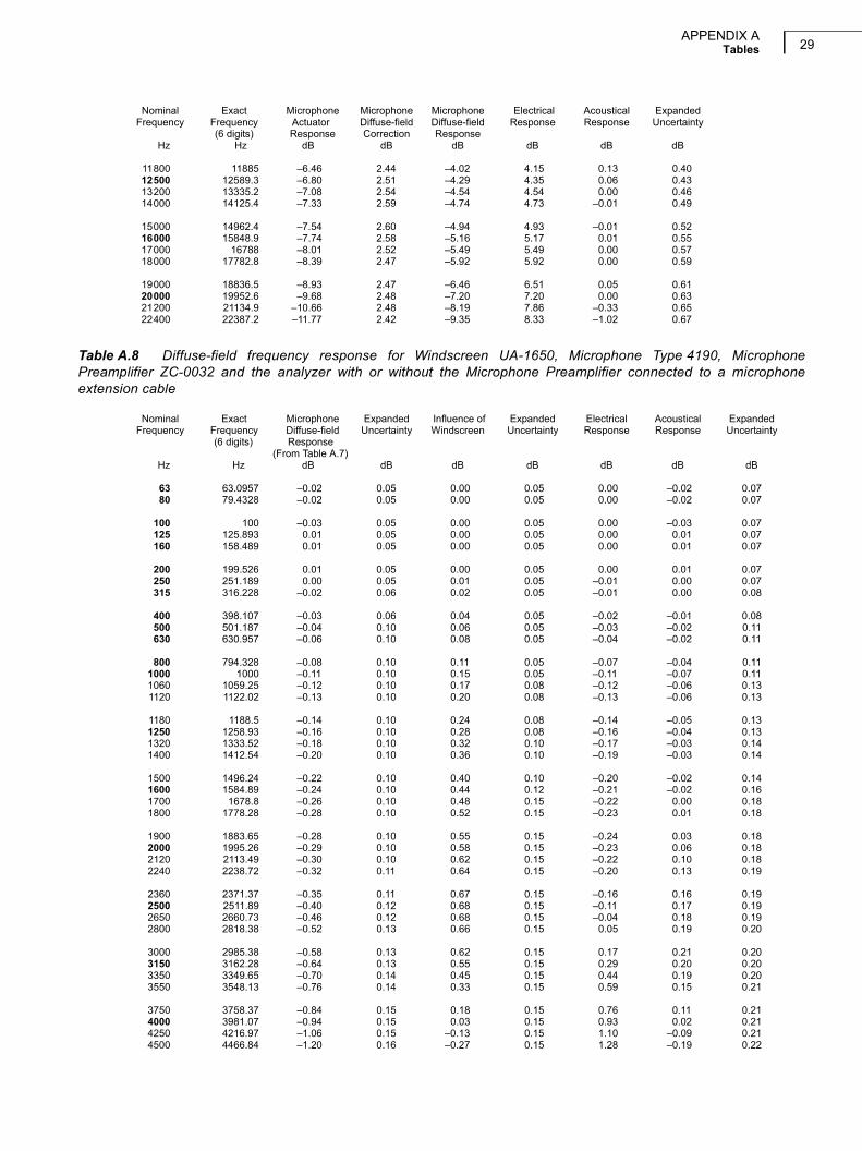
Table A.7 Diffuse-field frequency response for Microphone Type 4190, Microphone Preamplifier ZC-0032 and theanalyzer with or without the Microphone Preamplifier connected to a microphone extension cable
Nominal Exact Microphone Microphone Microphone Electrical Acoustical ExpandedFrequency Frequency Actuator Diffuse-field Diffuse-field Response Response Uncertainty
(6 digits) Response Correction ResponseHz Hz dB dB dB dB dB dB
63 63.0957 –0.02 0.00 –0.02 0.00 –0.02 0.0580 79.4328 –0.02 0.00 –0.02 0.00 –0.02 0.05
100 100 –0.03 0.00 –0.03 0.00 –0.03 0.05125 125.893 0.01 0.00 0.01 0.00 0.01 0.05160 158.489 0.01 0.00 0.01 0.00 0.01 0.05
200 199.526 0.01 0.00 0.01 0.00 0.01 0.05250 251.189 0.00 0.00 0.00 0.01 0.01 0.05315 316.228 –0.01 –0.01 –0.02 0.01 –0.01 0.06
400 398.107 –0.02 –0.01 –0.03 0.01 –0.02 0.06500 501.187 –0.03 –0.01 –0.04 0.02 –0.02 0.10630 630.957 –0.04 –0.02 –0.06 0.03 –0.03 0.10
800 794.328 –0.06 –0.02 –0.08 0.05 –0.03 0.101000 1000 –0.09 –0.02 –0.11 0.07 –0.04 0.101060 1059.25 –0.10 –0.02 –0.12 0.08 –0.04 0.101120 1122.02 –0.11 –0.02 –0.13 0.09 –0.04 0.10
1180 1188.5 –0.12 –0.03 –0.14 0.10 –0.04 0.101250 1258.93 –0.13 –0.03 –0.16 0.11 –0.05 0.101320 1333.52 –0.14 –0.04 –0.18 0.12 –0.06 0.101400 1412.54 –0.16 –0.05 –0.20 0.14 –0.06 0.10
1500 1496.24 –0.17 –0.05 –0.22 0.15 –0.07 0.101600 1584.89 –0.19 –0.05 –0.24 0.17 –0.07 0.101700 1678.8 –0.21 –0.05 –0.26 0.19 –0.07 0.101800 1778.28 –0.23 –0.04 –0.28 0.22 –0.06 0.10
1900 1883.65 –0.26 –0.03 –0.28 0.24 –0.04 0.102000 1995.26 –0.29 0.00 –0.29 0.27 –0.02 0.102120 2113.49 –0.32 0.02 –0.30 0.30 0.00 0.102240 2238.72 –0.35 0.04 –0.32 0.33 0.01 0.11
2360 2371.37 –0.39 0.04 –0.35 0.37 0.02 0.112500 2511.89 –0.44 0.04 –0.40 0.42 0.02 0.122650 2660.73 –0.49 0.03 –0.46 0.46 0.00 0.122800 2818.38 –0.54 0.03 –0.52 0.51 –0.01 0.13
3000 2985.38 –0.60 0.03 –0.58 0.57 –0.01 0.133150 3162.28 –0.67 0.04 –0.64 0.64 0.00 0.133350 3349.65 –0.75 0.05 –0.70 0.70 0.00 0.143550 3548.13 –0.83 0.07 –0.76 0.78 0.02 0.14
3750 3758.37 –0.92 0.09 –0.84 0.86 0.02 0.154000 3981.07 –1.03 0.09 –0.94 0.96 0.02 0.154250 4216.97 –1.14 0.08 –1.06 1.05 –0.01 0.154500 4466.84 –1.27 0.07 –1.20 1.16 –0.04 0.16
4750 4731.51 –1.40 0.09 –1.32 1.28 –0.03 0.165000 5011.87 –1.56 0.14 –1.42 1.40 –0.02 0.165300 5308.84 –1.72 0.19 –1.53 1.54 0.01 0.175600 5623.41 –1.91 0.24 –1.67 1.68 0.01 0.17
6000 5956.62 –2.11 0.28 –1.83 1.83 0.00 0.176300 6309.57 –2.32 0.32 –2.01 1.99 –0.02 0.186700 6683.44 –2.56 0.39 –2.17 2.16 –0.01 0.187100 7079.46 –2.82 0.47 –2.35 2.34 –0.01 0.18
7500 7498.94 –3.11 0.63 –2.48 2.53 0.05 0.198000 7943.28 –3.42 0.75 –2.67 2.72 0.05 0.198500 8413.95 –3.77 0.87 –2.89 2.92 0.03 0.229000 8912.51 –4.17 1.03 –3.14 3.13 –0.01 0.25
9500 9440.61 –4.62 1.23 –3.38 3.33 –0.05 0.2810000 10000 –5.10 1.53 –3.57 3.54 –0.03 0.3110600 10592.5 –5.59 1.86 –3.73 3.75 0.02 0.3411200 11220.2 –6.05 2.20 –3.86 3.95 0.09 0.37
APPENDIX ATables 29
Nominal Exact Microphone Microphone Microphone Electrical Acoustical ExpandedFrequency Frequency Actuator Diffuse-field Diffuse-field Response Response Uncertainty
(6 digits) Response Correction ResponseHz Hz dB dB dB dB dB dB
11800 11885 –6.46 2.44 –4.02 4.15 0.13 0.4012500 12589.3 –6.80 2.51 –4.29 4.35 0.06 0.4313200 13335.2 –7.08 2.54 –4.54 4.54 0.00 0.4614000 14125.4 –7.33 2.59 –4.74 4.73 –0.01 0.49
15000 14962.4 –7.54 2.60 –4.94 4.93 –0.01 0.5216000 15848.9 –7.74 2.58 –5.16 5.17 0.01 0.5517000 16788 –8.01 2.52 –5.49 5.49 0.00 0.5718000 17782.8 –8.39 2.47 –5.92 5.92 0.00 0.59
19000 18836.5 –8.93 2.47 –6.46 6.51 0.05 0.6120000 19952.6 –9.68 2.48 –7.20 7.20 0.00 0.6321200 21134.9 –10.66 2.48 –8.19 7.86 –0.33 0.6522400 22387.2 –11.77 2.42 –9.35 8.33 –1.02 0.67
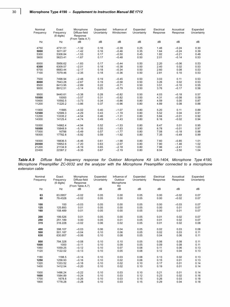
Table A.8 Diffuse-field frequency response for Windscreen UA-1650, Microphone Type 4190, MicrophonePreamplifier ZC-0032 and the analyzer with or without the Microphone Preamplifier connected to a microphoneextension cable
Nominal Exact Microphone Expanded Influence of Expanded Electrical Acoustical ExpandedFrequency Frequency Diffuse-field Uncertainty Windscreen Uncertainty Response Response Uncertainty
(6 digits) Response(From Table A.7)
Hz Hz dB dB dB dB dB dB dB
63 63.0957 –0.02 0.05 0.00 0.05 0.00 –0.02 0.0780 79.4328 –0.02 0.05 0.00 0.05 0.00 –0.02 0.07
100 100 –0.03 0.05 0.00 0.05 0.00 –0.03 0.07125 125.893 0.01 0.05 0.00 0.05 0.00 0.01 0.07160 158.489 0.01 0.05 0.00 0.05 0.00 0.01 0.07
200 199.526 0.01 0.05 0.00 0.05 0.00 0.01 0.07250 251.189 0.00 0.05 0.01 0.05 –0.01 0.00 0.07315 316.228 –0.02 0.06 0.02 0.05 –0.01 0.00 0.08
400 398.107 –0.03 0.06 0.04 0.05 –0.02 –0.01 0.08500 501.187 –0.04 0.10 0.06 0.05 –0.03 –0.02 0.11630 630.957 –0.06 0.10 0.08 0.05 –0.04 –0.02 0.11
800 794.328 –0.08 0.10 0.11 0.05 –0.07 –0.04 0.111000 1000 –0.11 0.10 0.15 0.05 –0.11 –0.07 0.111060 1059.25 –0.12 0.10 0.17 0.08 –0.12 –0.06 0.131120 1122.02 –0.13 0.10 0.20 0.08 –0.13 –0.06 0.13
1180 1188.5 –0.14 0.10 0.24 0.08 –0.14 –0.05 0.131250 1258.93 –0.16 0.10 0.28 0.08 –0.16 –0.04 0.131320 1333.52 –0.18 0.10 0.32 0.10 –0.17 –0.03 0.141400 1412.54 –0.20 0.10 0.36 0.10 –0.19 –0.03 0.14
1500 1496.24 –0.22 0.10 0.40 0.10 –0.20 –0.02 0.141600 1584.89 –0.24 0.10 0.44 0.12 –0.21 –0.02 0.161700 1678.8 –0.26 0.10 0.48 0.15 –0.22 0.00 0.181800 1778.28 –0.28 0.10 0.52 0.15 –0.23 0.01 0.18
1900 1883.65 –0.28 0.10 0.55 0.15 –0.24 0.03 0.182000 1995.26 –0.29 0.10 0.58 0.15 –0.23 0.06 0.182120 2113.49 –0.30 0.10 0.62 0.15 –0.22 0.10 0.182240 2238.72 –0.32 0.11 0.64 0.15 –0.20 0.13 0.19
2360 2371.37 –0.35 0.11 0.67 0.15 –0.16 0.16 0.192500 2511.89 –0.40 0.12 0.68 0.15 –0.11 0.17 0.192650 2660.73 –0.46 0.12 0.68 0.15 –0.04 0.18 0.192800 2818.38 –0.52 0.13 0.66 0.15 0.05 0.19 0.20
3000 2985.38 –0.58 0.13 0.62 0.15 0.17 0.21 0.203150 3162.28 –0.64 0.13 0.55 0.15 0.29 0.20 0.203350 3349.65 –0.70 0.14 0.45 0.15 0.44 0.19 0.203550 3548.13 –0.76 0.14 0.33 0.15 0.59 0.15 0.21
3750 3758.37 –0.84 0.15 0.18 0.15 0.76 0.11 0.214000 3981.07 –0.94 0.15 0.03 0.15 0.93 0.02 0.214250 4216.97 –1.06 0.15 –0.13 0.15 1.10 –0.09 0.214500 4466.84 –1.20 0.16 –0.27 0.15 1.28 –0.19 0.22
Microphone Type 4190 – Supplement to Instruction Manual BE 171230
Nominal Exact Microphone Expanded Influence of Expanded Electrical Acoustical ExpandedFrequency Frequency Diffuse-field Uncertainty Windscreen Uncertainty Response Response Uncertainty
(6 digits) Response(From Table A.7)
Hz Hz dB dB dB dB dB dB dB
4750 4731.51 –1.32 0.16 –0.39 0.25 1.46 –0.24 0.305000 5011.87 –1.42 0.16 –0.46 0.35 1.64 –0.24 0.395300 5308.84 –1.53 0.17 –0.50 0.45 1.82 –0.21 0.485600 5623.41 –1.67 0.17 –0.48 0.50 2.01 –0.14 0.53
6000 5956.62 –1.83 0.17 –0.44 0.50 2.20 –0.06 0.536300 6309.57 –2.01 0.18 –0.38 0.50 2.40 0.02 0.536700 6683.44 –2.17 0.18 –0.34 0.50 2.60 0.08 0.537100 7079.46 –2.35 0.18 –0.36 0.50 2.81 0.10 0.53
7500 7498.94 –2.48 0.19 –0.45 0.50 3.03 0.11 0.538000 7943.28 –2.67 0.19 –0.58 0.50 3.26 0.02 0.538500 8413.95 –2.89 0.22 –0.71 0.50 3.51 –0.10 0.559000 8912.51 –3.14 0.25 –0.79 0.50 3.76 –0.17 0.56
9500 9440.61 –3.38 0.28 –0.82 0.50 4.03 –0.18 0.5710000 10000 –3.57 0.31 –0.82 0.50 4.31 –0.08 0.5910600 10592.5 –3.73 0.34 –0.86 0.80 4.59 0.00 0.8711200 11220.2 –3.86 0.37 –0.96 0.80 4.89 0.08 0.88
11800 11885 –4.02 0.40 –1.07 0.80 5.20 0.11 0.8912500 12589.3 –4.29 0.43 –1.19 0.80 5.52 0.04 0.9113200 13335.2 –4.54 0.46 –1.31 0.80 5.84 –0.01 0.9214000 14125.4 –4.74 0.49 –1.43 0.80 6.16 –0.02 0.94
15000 14962.4 –4.94 0.52 –1.53 0.80 6.47 0.01 0.9516000 15848.9 –5.16 0.55 –1.63 0.80 6.78 –0.01 0.9717000 16788 –5.49 0.57 –1.77 0.80 7.08 –0.18 0.9818000 17782.8 –5.92 0.59 –1.92 0.80 7.35 –0.49 0.99
19000 18836.5 –6.46 0.61 –1.98 0.80 7.60 –0.85 1.0120000 19952.6 –7.20 0.63 –2.07 0.80 7.80 –1.46 1.0221200 21134.9 –8.19 0.65 –2.18 0.80 7.96 –2.41 1.0322400 22387.2 –9.35 0.67 –2.19 0.80 8.04 –3.50 1.04
Table A.9 Diffuse field frequency response for Outdoor Microphone Kit UA-1404, Microphone Type 4190,Microphone Preamplifier ZC-0032 and the analyzer with the Microphone Preamplifier connected to a microphoneextension cable
Nominal Exact Microphone Expanded Influence of Expanded Electrical Acoustical ExpandedFrequency Frequency Diffuse-field Uncertainty Outdoor Uncertainty Response Response Uncertainty
(6 digits) Response Microphone(From Table A.7) Kit
Hz Hz dB dB dB dB dB dB dB
63 63.0957 –0.02 0.05 0.00 0.05 0.00 –0.02 0.0780 79.4328 –0.02 0.05 0.00 0.05 0.00 –0.02 0.07
100 100 –0.03 0.05 0.00 0.05 0.00 –0.03 0.07125 125.893 0.01 0.05 0.00 0.05 0.00 0.01 0.07160 158.489 0.01 0.05 0.00 0.05 0.00 0.01 0.07
200 199.526 0.01 0.05 0.00 0.05 0.01 0.02 0.07250 251.189 0.00 0.05 0.01 0.05 0.01 0.02 0.07315 316.228 –0.02 0.06 0.02 0.05 0.01 0.02 0.08
400 398.107 –0.03 0.06 0.04 0.05 0.02 0.03 0.08500 501.187 –0.04 0.10 0.06 0.05 0.02 0.03 0.11630 630.957 –0.06 0.10 0.08 0.05 0.04 0.06 0.11
800 794.328 –0.08 0.10 0.10 0.05 0.06 0.08 0.111000 1000 –0.11 0.10 0.09 0.05 0.09 0.08 0.111060 1059.25 –0.12 0.10 0.07 0.08 0.11 0.06 0.131120 1122.02 –0.13 0.10 0.05 0.08 0.12 0.04 0.13
1180 1188.5 –0.14 0.10 0.03 0.08 0.13 0.02 0.131250 1258.93 –0.16 0.10 0.02 0.08 0.15 0.01 0.131320 1333.52 –0.18 0.10 0.02 0.10 0.17 0.01 0.141400 1412.54 –0.20 0.10 0.02 0.10 0.19 0.01 0.14
1500 1496.24 –0.22 0.10 0.03 0.10 0.21 0.01 0.141600 1584.89 –0.24 0.10 0.03 0.12 0.23 0.02 0.161700 1678.8 –0.26 0.10 0.03 0.15 0.26 0.03 0.181800 1778.28 –0.28 0.10 0.03 0.15 0.29 0.04 0.18

APPENDIX ATables 31
Nominal Exact Microphone Expanded Influence of Expanded Electrical Acoustical ExpandedFrequency Frequency Diffuse-field Uncertainty Outdoor Uncertainty Response Response Uncertainty
(6 digits) Response Microphone(From Table A.7) Kit
Hz Hz dB dB dB dB dB dB dB
1900 1883.65 –0.28 0.10 0.02 0.15 0.33 0.06 0.182000 1995.26 –0.29 0.10 –0.01 0.15 0.37 0.07 0.182120 2113.49 –0.30 0.10 –0.03 0.15 0.41 0.08 0.182240 2238.72 –0.32 0.11 –0.05 0.15 0.46 0.09 0.19
2360 2371.37 –0.35 0.11 –0.08 0.15 0.52 0.09 0.192500 2511.89 –0.40 0.12 –0.10 0.15 0.58 0.08 0.192650 2660.73 –0.46 0.12 –0.13 0.15 0.65 0.06 0.192800 2818.38 –0.52 0.13 –0.18 0.15 0.73 0.03 0.20
3000 2985.38 –0.58 0.13 –0.23 0.15 0.81 0.00 0.203150 3162.28 –0.64 0.13 –0.29 0.15 0.91 –0.01 0.203350 3349.65 –0.70 0.14 –0.35 0.15 1.02 –0.02 0.203550 3548.13 –0.76 0.14 –0.40 0.15 1.14 –0.03 0.21
3750 3758.37 –0.84 0.15 –0.46 0.15 1.27 –0.03 0.214000 3981.07 –0.94 0.15 –0.50 0.15 1.42 –0.02 0.214250 4216.97 –1.06 0.15 –0.52 0.15 1.58 0.00 0.214500 4466.84 –1.20 0.16 –0.55 0.15 1.75 0.01 0.22
4750 4731.51 –1.32 0.16 –0.60 0.25 1.94 0.02 0.305000 5011.87 –1.42 0.16 –0.70 0.35 2.14 0.02 0.395300 5308.84 –1.53 0.17 –0.83 0.45 2.36 0.00 0.485600 5623.41 –1.67 0.17 –0.94 0.50 2.57 –0.04 0.53
6000 5956.62 –1.83 0.17 –1.01 0.50 2.77 –0.07 0.536300 6309.57 –2.01 0.18 –1.00 0.50 2.95 –0.06 0.536700 6683.44 –2.17 0.18 –0.89 0.50 3.07 0.00 0.537100 7079.46 –2.35 0.18 –0.67 0.50 3.10 0.09 0.53
7500 7498.94 –2.48 0.19 –0.42 0.50 3.02 0.12 0.538000 7943.28 –2.67 0.19 –0.08 0.50 2.84 0.10 0.538500 8413.95 –2.89 0.22 0.30 0.50 2.60 0.00 0.559000 8912.51 –3.14 0.25 0.67 0.50 2.37 –0.10 0.56
9500 9440.61 –3.38 0.28 1.00 0.50 2.23 –0.15 0.5710000 10000 –3.57 0.31 1.23 0.50 2.21 –0.13 0.5910600 10592.5 –3.73 0.34 1.40 0.80 2.33 0.00 0.8711200 11220.2 –3.86 0.37 1.47 0.80 2.55 0.16 0.88
11800 11885 –4.02 0.40 1.47 0.80 2.85 0.31 0.8912500 12589.3 –4.29 0.43 1.36 0.80 3.20 0.27 0.9113200 13335.2 –4.54 0.46 1.02 0.80 3.58 0.06 0.9214000 14125.4 –4.74 0.49 0.69 0.80 3.98 –0.07 0.94
15000 14962.4 –4.94 0.52 0.43 0.80 4.38 –0.13 0.9516000 15848.9 –5.16 0.55 0.25 0.80 4.78 –0.13 0.9717000 16788 –5.49 0.57 0.34 0.80 5.15 0.00 0.9818000 17782.8 –5.92 0.59 0.56 0.80 5.50 0.14 0.99
19000 18836.5 –6.46 0.61 0.63 0.80 5.81 –0.02 1.0120000 19952.6 –7.20 0.63 0.49 0.80 6.07 –0.64 1.0221200 21134.9 –8.19 0.65 0.40 0.80 6.26 –1.52 1.0322400 22387.2 –9.35 0.67 –0.02 0.80 6.37 –3.00 1.04
A.4 Free-field Frequency Responses for Diffuse-field Calibrated Instruments
Free-field frequency response in the reference direction for diffuse-field calibrated instruments according toIEC 60651 and IEC 60804. Measured with plane progressive sinusoidal sound waves incident from thereference direction and the instrument’s Sound Field Correction parameter set to Diffuse-field.

Microphone Type 4190 – Supplement to Instruction Manual BE 171232
Table A.10 Free-field 0 frequency response with the Sound Field Correction parameter set to Diffuse-field for theconfigurations for which there are specified normal Free-field responses
Nominal Exact Configuration Configuration Configuration Configuration ConfigurationFrequency Frequency as in as in as in as in as in
(6 digits) Table A.2 Table A.3 Table A.4 Table A.5 Table A.6Hz Hz dB dB dB dB dB
63 63.0957 –0.02 –0.02 –0.02 –0.02 –0.0280 79.4328 –0.02 –0.02 –0.02 –0.02 –0.02
100 100 –0.03 –0.03 –0.03 –0.03 –0.03125 125.893 0.01 0.01 0.01 0.01 0.01160 158.489 0.01 0.02 0.01 0.02 0.01
200 199.526 0.01 0.03 0.01 0.03 0.02250 251.189 0.01 0.08 0.00 0.07 0.03315 316.228 0.01 0.14 0.01 0.14 0.05
400 398.107 0.00 0.21 0.02 0.23 0.09500 501.187 0.01 0.24 0.03 0.26 0.12630 630.957 0.03 0.10 0.06 0.13 0.18
800 794.328 0.06 –0.06 0.07 –0.04 0.251000 1000 0.08 0.01 0.09 0.02 0.291060 1059.25 0.10 –0.01 0.11 0.01 0.281120 1122.02 0.11 –0.07 0.14 –0.04 0.25
1180 1188.5 0.12 –0.14 0.17 –0.09 0.231250 1258.93 0.13 –0.17 0.19 –0.12 0.221320 1333.52 0.15 –0.10 0.22 –0.02 0.221400 1412.54 0.17 0.09 0.25 0.17 0.24
1500 1496.24 0.18 0.27 0.28 0.38 0.271600 1584.89 0.20 0.37 0.32 0.49 0.311700 1678.8 0.22 0.29 0.36 0.43 0.361800 1778.28 0.25 0.13 0.39 0.27 0.43
1900 1883.65 0.28 0.06 0.43 0.22 0.522000 1995.26 0.31 0.22 0.48 0.39 0.612120 2113.49 0.34 0.45 0.52 0.63 0.682240 2238.72 0.37 0.46 0.55 0.64 0.73
2360 2371.37 0.41 0.11 0.60 0.30 0.782500 2511.89 0.46 0.29 0.65 0.48 0.812650 2660.73 0.50 0.68 0.70 0.89 0.792800 2818.38 0.55 0.65 0.77 0.87 0.75
3000 2985.38 0.61 0.49 0.84 0.72 0.793150 3162.28 0.68 0.84 0.88 1.04 0.873350 3349.65 0.74 0.77 0.92 0.95 0.933550 3548.13 0.81 0.69 0.93 0.80 1.13
3750 3758.37 0.90 1.10 0.96 1.16 1.364000 3981.07 1.00 0.91 1.02 0.92 1.474250 4216.97 1.09 1.08 1.09 1.08 1.664500 4466.84 1.19 1.29 1.18 1.28 1.76
4750 4731.51 1.31 1.14 1.31 1.14 1.925000 5011.87 1.42 1.18 1.47 1.23 1.995300 5308.84 1.55 1.45 1.66 1.56 2.175600 5623.41 1.67 1.62 1.85 1.80 2.22
6000 5956.62 1.81 1.84 2.05 2.08 2.386300 6309.57 1.95 2.00 2.25 2.30 2.486700 6683.44 2.09 2.14 2.37 2.42 2.667100 7079.46 2.26 2.23 2.45 2.42 2.73
7500 7498.94 2.46 2.38 2.60 2.52 2.828000 7943.28 2.69 2.60 2.82 2.73 2.758500 8413.95 2.90 2.71 3.02 2.83 2.579000 8912.51 3.10 3.10 3.29 3.28 2.40
9500 9440.61 3.31 3.42 3.55 3.66 2.3610000 10000 3.56 3.71 3.82 3.97 2.4010600 10592.5 3.85 3.71 4.06 3.92 2.5711200 11220.2 4.17 4.04 4.37 4.24 2.83
APPENDIX ATables 33
Nominal Exact Configuration Configuration Configuration Configuration ConfigurationFrequency Frequency as in as in as in as in as in
(6 digits) Table A.2 Table A.3 Table A.4 Table A.5 Table A.6Hz Hz dB dB dB dB dB
11800 11885 4.50 4.58 4.69 4.77 3.0612500 12589.3 4.75 4.90 5.04 5.19 3.0913200 13335.2 5.00 5.00 5.30 5.31 2.9614000 14125.4 5.29 5.22 5.60 5.52 2.76
15000 14962.4 5.63 5.67 5.96 6.01 2.5516000 15848.9 6.02 6.13 6.30 6.42 2.2617000 16788 6.39 6.38 6.48 6.47 1.9718000 17782.8 6.79 6.73 6.62 6.55 1.80
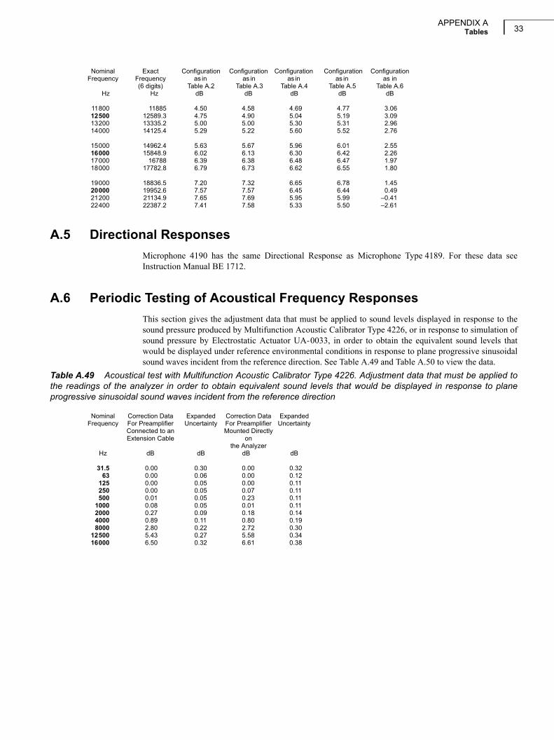
19000 18836.5 7.20 7.32 6.65 6.78 1.4520000 19952.6 7.57 7.57 6.45 6.44 0.4921200 21134.9 7.65 7.69 5.95 5.99 –0.4122400 22387.2 7.41 7.58 5.33 5.50 –2.61
A.5 Directional Responses
Microphone 4190 has the same Directional Response as Microphone Type 4189. For these data seeInstruction Manual BE 1712.
A.6 Periodic Testing of Acoustical Frequency Responses
This section gives the adjustment data that must be applied to sound levels displayed in response to thesound pressure produced by Multifunction Acoustic Calibrator Type 4226, or in response to simulation ofsound pressure by Electrostatic Actuator UA-0033, in order to obtain the equivalent sound levels thatwould be displayed under reference environmental conditions in response to plane progressive sinusoidalsound waves incident from the reference direction. See Table A.49 and Table A.50 to view the data.
Table A.49 Acoustical test with Multifunction Acoustic Calibrator Type 4226. Adjustment data that must be applied tothe readings of the analyzer in order to obtain equivalent sound levels that would be displayed in response to planeprogressive sinusoidal sound waves incident from the reference direction
Nominal Correction Data Expanded Correction Data ExpandedFrequency For Preamplifier Uncertainty For Preamplifier Uncertainty
Connected to an Mounted DirectlyExtension Cable on
the AnalyzerHz dB dB dB dB
31.5 0.00 0.30 0.00 0.3263 0.00 0.06 0.00 0.12
125 0.00 0.05 0.00 0.11250 0.00 0.05 0.07 0.11500 0.01 0.05 0.23 0.11
1000 0.08 0.05 0.01 0.112000 0.27 0.09 0.18 0.144000 0.89 0.11 0.80 0.198000 2.80 0.22 2.72 0.30
12500 5.43 0.27 5.58 0.3416000 6.50 0.32 6.61 0.38
Microphone Type 4190 – Supplement to Instruction Manual BE 171234
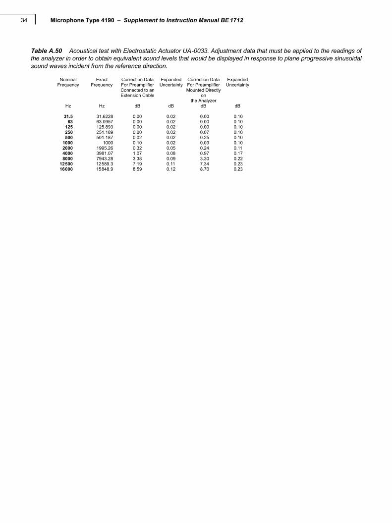
Table A.50 Acoustical test with Electrostatic Actuator UA-0033. Adjustment data that must be applied to the readings ofthe analyzer in order to obtain equivalent sound levels that would be displayed in response to plane progressive sinusoidalsound waves incident from the reference direction.
Nominal Exact Correction Data Expanded Correction Data ExpandedFrequency Frequency For Preamplifier Uncertainty For Preamplifier Uncertainty
Connected to an Mounted DirectlyExtension Cable on
the AnalyzerHz Hz dB dB dB dB
31.5 31.6228 0.00 0.02 0.00 0.1063 63.0957 0.00 0.02 0.00 0.10
125 125.893 0.00 0.02 0.00 0.10250 251.189 0.00 0.02 0.07 0.10500 501.187 0.02 0.02 0.25 0.10
1000 1000 0.10 0.02 0.03 0.102000 1995.26 0.32 0.05 0.24 0.114000 3981.07 1.07 0.08 0.97 0.178000 7943.28 3.38 0.09 3.30 0.22
12500 12589.3 7.19 0.11 7.34 0.2316000 15848.9 8.59 0.12 8.70 0.23
35
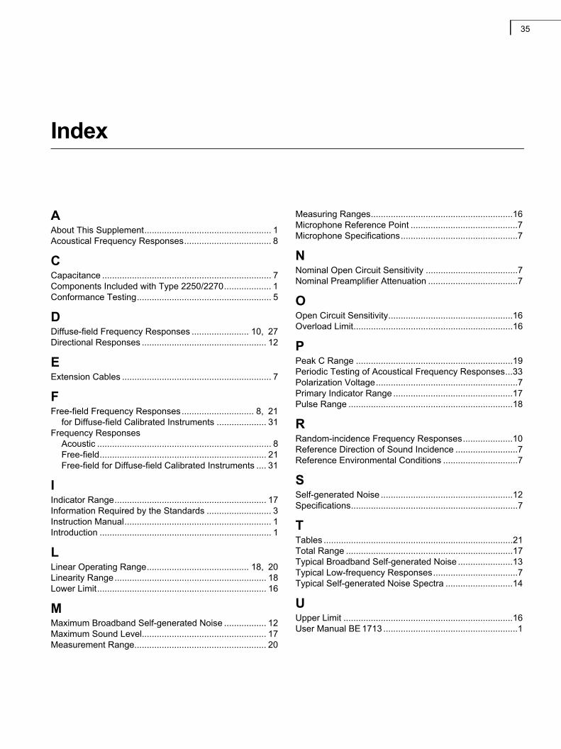
Index
AAbout This Supplement................................................... 1Acoustical Frequency Responses................................... 8
CCapacitance .................................................................... 7Components Included with Type 2250/2270................... 1Conformance Testing...................................................... 5
DDiffuse-field Frequency Responses ....................... 10, 27Directional Responses .................................................. 12
EExtension Cables ............................................................ 7
FFree-field Frequency Responses............................. 8, 21
for Diffuse-field Calibrated Instruments .................... 31Frequency Responses
Acoustic ...................................................................... 8Free-field................................................................... 21Free-field for Diffuse-field Calibrated Instruments .... 31
IIndicator Range............................................................. 17Information Required by the Standards .......................... 3Instruction Manual........................................................... 1Introduction ..................................................................... 1
LLinear Operating Range......................................... 18, 20Linearity Range............................................................. 18Lower Limit.................................................................... 16
MMaximum Broadband Self-generated Noise ................. 12Maximum Sound Level.................................................. 17Measurement Range..................................................... 20
Measuring Ranges.........................................................16Microphone Reference Point ...........................................7Microphone Specifications...............................................7
NNominal Open Circuit Sensitivity .....................................7Nominal Preamplifier Attenuation ....................................7
OOpen Circuit Sensitivity..................................................16Overload Limit................................................................16
PPeak C Range ...............................................................19Periodic Testing of Acoustical Frequency Responses...33Polarization Voltage.........................................................7Primary Indicator Range ................................................17Pulse Range ..................................................................18
RRandom-incidence Frequency Responses....................10Reference Direction of Sound Incidence .........................7Reference Environmental Conditions ..............................7
SSelf-generated Noise .....................................................12Specifications...................................................................7
TTables ............................................................................21Total Range ...................................................................17Typical Broadband Self-generated Noise ......................13Typical Low-frequency Responses..................................7Typical Self-generated Noise Spectra ...........................14
UUpper Limit ....................................................................16User Manual BE 1713 ......................................................1

Microphone Type 4190 – Supplement to Instruction Manual BE 171236


TechnicalDocumentation
Microphone Type 4190for Hand-held Analyzer Types 2250, 2250-L and 2270
Supplement to Instruction Manual BE 1712
HEADQUARTERS: Brüel & Kjær Sound & Vibration Measurement A/S · DK-2850 Nærum · DenmarkTelephone: +45 7741 2000 · Fax: +45 4580 1405 · www.bksv.com · [email protected]
Local representatives and service organisations worldwide
ËBE-1805---"Î
English BE 1805 – 14