
Technical Document
14
http://www.natoll.Gom NATIONAL OILWELL VARCO TABLE OF CONTENTS 1.0. SCOPE ......................................................................... 2 2.0. REFERENCE ..................................................................... 3 3.0. National Aerospace Standard, Fluid cleanliness 1 CLEANLINESS ..................... 4 3.1. Cleaning of tubes during and after pre-fabrication - General guide: .... 4 3.1.1. Mechanical cleaning of tubes ........................................... 4 3.1.2. Chemical cleaning of tubes ............................................. 4 3.1.3. Alkaline degreasing .................................................... 4 3.1.4. Water rinsing .......................................................... 4 3.1.5. Pickling (only Carbon pipes and not to seamless cold drawn SS pipes) ...4 3.1.6. Alternative pickling (supplier’s request) .............................. 4 3.1.7. Phosphoric acid pickling ............................................... 4 3.1.8. Water rinsing .......................................................... 4 3.1.9. Neutralisation ......................................................... 5 3.1.10. Water rinsing .......................................................... 5 3.1.11. Drying ................................................................. 5 3.1.12. Surface treatment ...................................................... 5 3.1.13. Passivation of Stainless Steel Pipes ................................... 5 3.1.14. Storage of tubes and tube parts ........................................ 6 4.0. FLUSHING ...................................................................... 7 4.1. Preparation of a Flushing Plan ......................................... 7 4.2. Hydraulic Pipe Flushing ................................................ 7 4.2.1. Specification of Flushing Flow ......................................... 7 4.2.2. Equipment needed during flushing ....................................... 8 4.2.3. Eventual 250-ml sample bottle, which is cleaned and sealed of a certified supplier.Check List to be made up before flushing ............ 8 4.3. Water Pipe Flushing (Hydro flushing) ................................... 9 4.4. Air Pipe Flushing - Pressurised air shock blowing (PAS) ............... 10 4.5. Mud, Cement and Vent Pipe Flushing See NORSOK L-CR-004 ................ 10 4.6. Pneumatic flushing .................................................... 10 5.0. INSPECTION OF CLEANLINESS LEVEL .............................................. 11 5.1. OFF line automatic particle counter ................................... 11 5.2. Fluid sampling ........................................................ 11 5.3. ON line automatic particle counter .................................... 11 6.0. PRESERVATION ................................................................. 12 7.0. DOCUMENTATION ................................................................ 12 7.1. General ............................................................... 12 7.2. Completion Records .................................................... 12 7.3. Completion Record Sheet example ....................................... 12 8.0. QA & SAFETY .................................................................. 13 8.1. Quality Assurance ..................................................... 13 8.2. ISO 4406 SCALE NUMBERS - Basis of code ................................ 13 9.0. COMPLETION RECORD SHEET EXAMPLE .............................................. 14
-
Upload
nguyen-thanh-cuong -
Category
Documents
-
view
57 -
download
0
description
Construction Document
Transcript of Technical Document
http://www.natoll.Gom NATIONAL OILWELL VARCO
TABLE OF CONTENTS
1.0. SCOPE ......................................................................... 2
2.0. REFERENCE ..................................................................... 3
3.0. National Aerospace Standard, Fluid cleanliness1CLEANLINESS ..................... 4 3.1. Cleaning of tubes during and after pre-fabrication - General guide: .... 4 3.1.1. Mechanical cleaning of tubes ........................................... 4 3.1.2. Chemical cleaning of tubes ............................................. 4 3.1.3. Alkaline degreasing .................................................... 4 3.1.4. Water rinsing .......................................................... 4 3.1.5. Pickling (only Carbon pipes and not to seamless cold drawn SS pipes) ... 4 3.1.6. Alternative pickling (supplier’s request) .............................. 4 3.1.7. Phosphoric acid pickling ............................................... 4 3.1.8. Water rinsing .......................................................... 4 3.1.9. Neutralisation ......................................................... 5 3.1.10. Water rinsing .......................................................... 5 3.1.11. Drying ................................................................. 5 3.1.12. Surface treatment ...................................................... 5 3.1.13. Passivation of Stainless Steel Pipes ................................... 5 3.1.14. Storage of tubes and tube parts ........................................ 6
4.0. FLUSHING ...................................................................... 7 4.1. Preparation of a Flushing Plan ......................................... 7 4.2. Hydraulic Pipe Flushing ................................................ 7 4.2.1. Specification of Flushing Flow ......................................... 7 4.2.2. Equipment needed during flushing ....................................... 8 4.2.3. Eventual 250-ml sample bottle, which is cleaned and sealed of a
certified supplier.Check List to be made up before flushing ............ 8 4.3. Water Pipe Flushing (Hydro flushing) ................................... 9 4.4. Air Pipe Flushing - Pressurised air shock blowing (PAS) ............... 10 4.5. Mud, Cement and Vent Pipe Flushing See NORSOK L-CR-004 ................ 10 4.6. Pneumatic flushing .................................................... 10
5.0. INSPECTION OF CLEANLINESS LEVEL .............................................. 11 5.1. OFF line automatic particle counter ................................... 11 5.2. Fluid sampling ........................................................ 11 5.3. ON line automatic particle counter .................................... 11
6.0. PRESERVATION ................................................................. 12
7.0. DOCUMENTATION ................................................................ 12 7.1. General ............................................................... 12 7.2. Completion Records .................................................... 12 7.3. Completion Record Sheet example ....................................... 12
8.0. QA & SAFETY .................................................................. 13 8.1. Quality Assurance ..................................................... 13 8.2. ISO 4406 SCALE NUMBERS - Basis of code ................................ 13
9.0. COMPLETION RECORD SHEET EXAMPLE .............................................. 14
2
http://www.natoll.Gom NATIONAL OILWELL VARCO
1.0. SCOPE
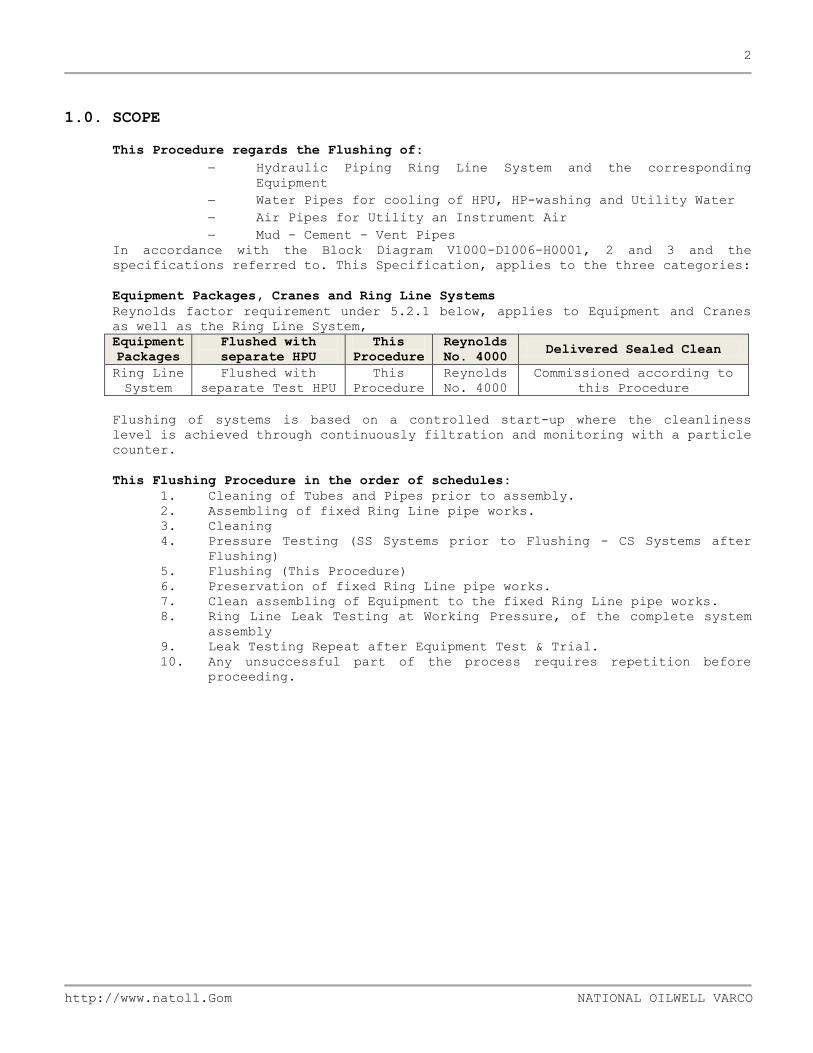
This Procedure regards the Flushing of:
Hydraulic Piping Ring Line System and the corresponding
Equipment
Water Pipes for cooling of HPU, HP-washing and Utility Water
Air Pipes for Utility an Instrument Air
Mud - Cement - Vent Pipes
In accordance with the Block Diagram V1000-D1006-H0001, 2 and 3 and the
specifications referred to. This Specification, applies to the three categories:
Equipment Packages, Cranes and Ring Line Systems
Reynolds factor requirement under 5.2.1 below, applies to Equipment and Cranes
as well as the Ring Line System,
Equipment
Packages
Flushed with
separate HPU
This
Procedure
Reynolds
No. 4000 Delivered Sealed Clean
Ring Line
System
Flushed with
separate Test HPU
This
Procedure
Reynolds
No. 4000
Commissioned according to
this Procedure
Flushing of systems is based on a controlled start-up where the cleanliness
level is achieved through continuously filtration and monitoring with a particle
counter.
This Flushing Procedure in the order of schedules:
1. Cleaning of Tubes and Pipes prior to assembly.
2. Assembling of fixed Ring Line pipe works.
3. Cleaning
4. Pressure Testing (SS Systems prior to Flushing - CS Systems after
Flushing)
5. Flushing (This Procedure)
6. Preservation of fixed Ring Line pipe works.
7. Clean assembling of Equipment to the fixed Ring Line pipe works.
8. Ring Line Leak Testing at Working Pressure, of the complete system
assembly
9. Leak Testing Repeat after Equipment Test & Trial.
10. Any unsuccessful part of the process requires repetition before
proceeding.

3
http://www.natoll.Gom NATIONAL OILWELL VARCO
2.0. REFERENCE
The P.O specification and this Specification of the corresponding internal
National Oilwell Varco practise are ruling to all Suppliers and Sub-Suppliers
through all stages in the development of the System. Consequently any other
Reference should be waived by the Client in due time.
References for National Oilwell Varco guidance are:
National Oilwell Hydraulic Hand Book Rev.2 10.08.99
National Oilwell HL/T-16 PreservationNORSOK L-002
National Oilwell ISO 4021
NORSOK L-CR-004 and ANNEX B:
NORSOK Z-006 V1000-D1011-H0001, 2 & 3 NAS 1638
Piping Design, Layout and Stress Analysis Clean Mounting
(Report Format)
Oil Sampling
Piping Fabrication, Installation, Flushing and Testing,
Requirements for internal treatment of piping after prefab and
installation before commissioning.
Preservation of equipment and systems
Hydraulic Block Diagrams
4
http://www.natoll.Gom NATIONAL OILWELL VARCO
3.0. National Aerospace Standard, Fluid cleanliness1CLEANLINESS
3.1. Cleaning of tubes during and after pre-fabrication - General guide:
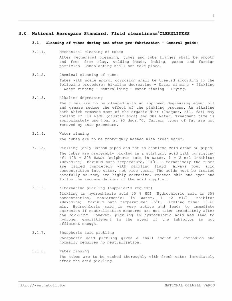
3.1.1. Mechanical cleaning of tubes
After mechanical cleaning, tubes and tube flanges shall be smooth
and free from slag, welding beads, baking, pores and foreign
particles. Sandblasting shall not take place.
3.1.2. Chemical cleaning of tubes
Tubes with scale and/or corrosion shall be treated according to the
following procedure: Alkaline degreasing - Water rinsing - Pickling
- Water rinsing - Neutralising - Water rinsing - Drying.
3.1.3. Alkaline degreasing
The tubes are to be cleaned with an approved degreasing agent oil
and grease reduce the effect of the pickling process. An alkaline
bath which removes most of the organic dirt (lacquer, oil, fat) may
consist of 10% NaOH (caustic soda) and 90% water. Treatment time is
approximately one hour at 90 degr.°C. Certain types of fat are not
removed by this procedure.
3.1.4. Water rinsing
The tubes are to be thoroughly washed with fresh water.
3.1.5. Pickling (only Carbon pipes and not to seamless cold drawn SS pipes)
The tubes are preferably pickled in a sulphuric acid bath consisting
of: 10% ÷ 20% H2SO4 (sulphuric acid in water, 1 ÷ 2 m/l Inhibitor
(Hexamine). Maximum bath temperature, 80°C. Alternatively the tubes
are filled completely with pickling fluid. Always pour acid
concentration into water, not vice versa. The acids must be treated
carefully as they are highly corrosive. Protect skin and eyes and
follow the recommendations of the acid supplier.
3.1.6. Alternative pickling (supplier’s request)
Pickling in hydrochloric acid 50 % HCI (Hydrochloric acid in 35%
concentration, non-arsenic) in water, 1 -2 ml/l Inhibitor
(Hexamine). Maximum bath temperature: 35°C, Pickling time: 10-60
min. Hydrochloric acid is very active and leads to immediate
corrosion if neutralisation measures are not taken immediately after
the pickling. However, pickling in hydrochloric acid may lead to
hydrogen embrittlement in the steel if the inhibitor is not
efficient enough.
3.1.7. Phosphoric acid pickling
Phosphoric acid pickling gives a small amount of corrosion and
normally requires no neutralisation.
3.1.8. Water rinsing
The tubes are to be washed thoroughly with fresh water immediately
after the acid pickling.
5
http://www.natoll.Gom NATIONAL OILWELL VARCO
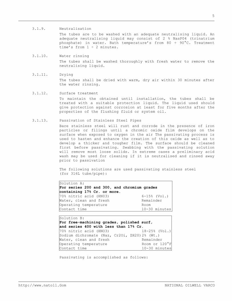
3.1.9. Neutralisation
The tubes are to be washed with an adequate neutralising liquid. An
adequate neutralising liquid may consist of 2 % NasP04 (trinatrium
phosphate) in water. Bath temperature’s from 80 ÷ 90°C. Treatment
time’s from 1 ÷ 2 minutes.
3.1.10. Water rinsing
The tubes shall be washed thoroughly with fresh water to remove the
neutralising liquid.
3.1.11. Drying
The tubes shall be dried with warm, dry air within 30 minutes after
the water rinsing.
3.1.12. Surface treatment
To maintain the obtained until installation, the tubes shall be
treated with a suitable protection liquid. The liquid used should
give protection against corrosion at least for five months after the
properties of the flushing fluid or system oil.
3.1.13. Passivation of Stainless Steel Pipes
Bare stainless steel will rust and corrode in the presence of iron
particles or filings until a chromic oxide film develops on the
surface when exposed to oxygen in the air The passivating process is
used to hasten and enhance the creation of this oxide as well as to
develop a thicker and tougher film. The surface should be cleaned
first before passivating. Swabbing with the passivating solution
will remove most loose solids. In extreme cases a preliminary acid
wash may be used for cleaning if it is neutralised and rinsed away
prior to passivation
The following solutions are used passivating stainless steel
(for 316L tube/pipe):
Solution A:
For series 200 and 300, and chromium grades
containing 17% Cr. or more.
70% nitric acid (HN03) 6-15% (Vol.)
Water, clean and fresh Remainder
Operating temperature Room
Contact time 10-30 minutes
Solution B:
For free-machining grades, polished surf,
and series 400 with less than 17% Cr.
70% nitric acid (HNO3) 18-25% (Vol.)
Sodium dichromate (Naz, Cr2Oi, ZH20) 2% (Wt.)
Water, clean and fresh Remainder
Operating temperature Room or 120°F
Contact time 10-30 minutes
Passivating is accomplished as follows:

6
http://www.natoll.Gom NATIONAL OILWELL VARCO
Immerse, flush or swab with passivation solution.
Flush the surface with clean fresh water (not sea water) to
remove all traces of acid. Subsequent ’’rust proofing” by
coating with oil or hydraulic fluid is unnecessary and
undesirable since this film serves only to hold dust and dirt.
It is important to close all pipe openings to carefully guard
against the entry of dirt until final installation is
complete.
Do not clean Stainless Steel Pipes with a wire brush as traces of
iron because it’s may be left on the surface.
3.1.14. Storage of tubes and tube parts
Cleaned and surface treated tubes and fittings have to be capped
immediately and should be stored in a dry place.
7
http://www.natoll.Gom NATIONAL OILWELL VARCO
4.0. FLUSHING
4.1. Preparation of a Flushing Plan
A Flushing Plan including Block Diagram for the specific system shall be
prepared. Special equipment for the Flushing, like supporting equipment,
loops, couplings, connectors etc. shall be listed and sketched at the
diagrams.
Cleaning shall be carried out prior to pressure testing and the Flushing
thereafter. General requirements for Flushing for specific systems are
listed in NORSOK L-CR-004 - table 1 in Annex B National Oilwell Varco
shall approve the Flushing Plan.
4.2. Hydraulic Pipe Flushing
Flushing of the Ring Line Piping System shall be performed in accordance
with the References noted and as a minimum satisfy:
NAS 1638 class 8 ♦ ISO 4406 17/14.
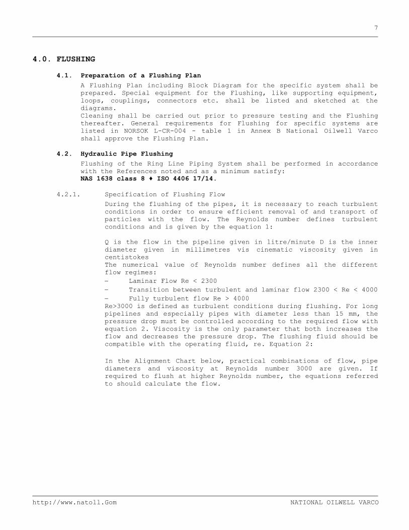
4.2.1. Specification of Flushing Flow
During the flushing of the pipes, it is necessary to reach turbulent
conditions in order to ensure efficient removal of and transport of
particles with the flow. The Reynolds number defines turbulent
conditions and is given by the equation 1:
Q is the flow in the pipeline given in litre/minute D is the inner
diameter given in millimetres vis cinematic viscosity given in
centistokes
The numerical value of Reynolds number defines all the different
flow regimes:
Laminar Flow Re < 2300
Transition between turbulent and laminar flow 2300 < Re < 4000
Fully turbulent flow Re > 4000
Re>3000 is defined as turbulent conditions during flushing. For long
pipelines and especially pipes with diameter less than 15 mm, the
pressure drop must be controlled according to the required flow with
equation 2. Viscosity is the only parameter that both increases the
flow and decreases the pressure drop. The flushing fluid should be
compatible with the operating fluid, re. Equation 2:
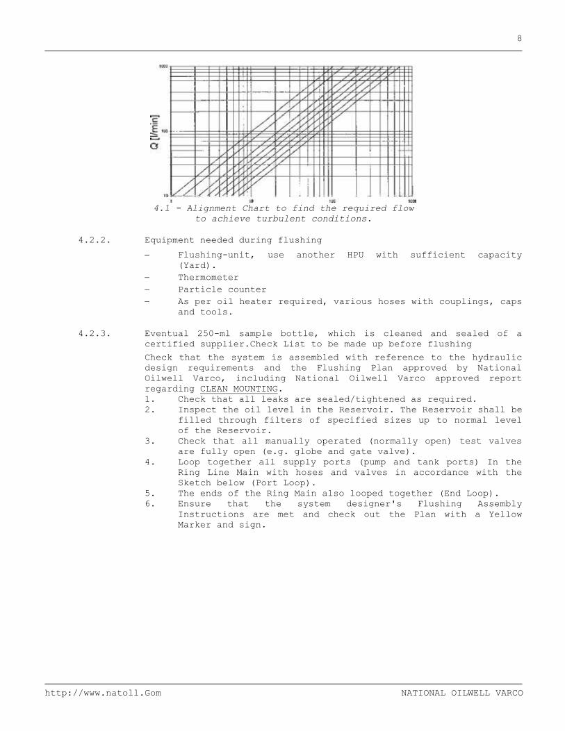
In the Alignment Chart below, practical combinations of flow, pipe
diameters and viscosity at Reynolds number 3000 are given. If
required to flush at higher Reynolds number, the equations referred
to should calculate the flow.
8
http://www.natoll.Gom NATIONAL OILWELL VARCO
4.1 - Alignment Chart to find the required flow
to achieve turbulent conditions.
4.2.2. Equipment needed during flushing
Flushing-unit, use another HPU with sufficient capacity
(Yard).
Thermometer
Particle counter
As per oil heater required, various hoses with couplings, caps
and tools.
4.2.3. Eventual 250-ml sample bottle, which is cleaned and sealed of a
certified supplier.Check List to be made up before flushing
Check that the system is assembled with reference to the hydraulic
design requirements and the Flushing Plan approved by National
Oilwell Varco, including National Oilwell Varco approved report
regarding CLEAN MOUNTING.
1. Check that all leaks are sealed/tightened as required.
2. Inspect the oil level in the Reservoir. The Reservoir shall be
filled through filters of specified sizes up to normal level
of the Reservoir.
3. Check that all manually operated (normally open) test valves
are fully open (e.g. globe and gate valve).
4. Loop together all supply ports (pump and tank ports) In the
Ring Line Main with hoses and valves in accordance with the
Sketch below (Port Loop).
5. The ends of the Ring Main also looped together (End Loop).
6. Ensure that the system designer's Flushing Assembly
Instructions are met and check out the Plan with a Yellow
Marker and sign.

9
http://www.natoll.Gom NATIONAL OILWELL VARCO
1. Start the pumps and filtrate the oil internally in the HPU
until NAS 1638 class 8 (ISO 4406 code 17/14) is achieved.
2. Circulate the oil and bleed air until the system is filled
with oil.
3. Heat the oil during running to 55÷60°C for VG 32 oil (60÷65°C
for VG 46 oil)1. The temperature shall be measured in the
reservoir. If this temperature is not possible to achieve
during normal running, a heater should be mounted and used.
4. Run flow through the port loops one loop at a time. Open the
valve with full effort for 3 minutes. Run through the rest of
the port loops in the same way.
5. Run the moving elements (actuator, hydraulic motor, etc.) one
by one.
6. Actuators are to be run with full effort at least 10 times in
each direction. Hydraulic motors are to be run with full
effort for 3 min. in each direction.
7. Monitor the cleanliness level with a particle counter. Sample
from the return line close to the return filter. Let at least
5 litres of oil circulate through the counter before sampling.
If the sample has NAS class 8 (ISO 17/14) or better, two new
samples shall be taken at once. If the target cleanliness
level is not achieved and it is over NAS class 11 stop the
pumps2. If the NAS class is between 8 and 11 repeat the
procedure with running of the moving elements until target
cleanliness level NAS class 8 is achieved.
8. The responsible person shall sign the specific equipments test
printouts from the particle counter which shall be attached to
the complete report.
4.3. Water Pipe Flushing (Hydro flushing)
See NORSOK L-CR-004 chapter 8, item 8.2; quote: “Chapter 8, item 8.2,
Hydro flushing: Items of equipment which would be sensitive to damage
during hydro flushing shall be removed, blocked or isolated. A list shall
be prepared and be part of the flush & test procedure.
Ball valves shall be flushed in fully open position.
All piping systems shall be flushed using high pressure jet flushing
equipment, such as rotating hose or rotating nozzle. Minimum pressure
shall be 600 Bar.
Below 4”, High Velocity Water Flushing (HVWF) may be used. Water velocity
shall be a minimum of 10m/s. On systems where high pressure jet flushing
cannot be used due to complicated shapes and/or long runs HVWF may be
used.
The flushing medium shall in general be fresh water. When flushing
stainless steel lines, the chloride ion content shall be less than 200ppm.
After flushing, the piping systems shall be completely drained and
protected against corrosion.
Ball valves shall be flushed fully open.”
1 Because of pump breakdown, the viscosity never should be lower then 16 cSt. The
viscosity is 16 cSt at 62°C for VG 32 oil and at 72°C for VG46 oil. These
temperatures must never be exceeded. 2 The superior that is responsible for the flushing is to be contacted for
consultation. Proportional valves are to be removed from the system and bypasses
put on the valve block.

10
http://www.natoll.Gom NATIONAL OILWELL VARCO
4.4. Air Pipe Flushing - Pressurised air shock blowing (PAS)
See NORSOK L-CR-004 chapter 8, item 8.3. We quote: “Chapter 8, item 8.3,
pressurised air shock blowing:
This meted may be used as an initial cleaning method for instrument air,
plant air and as an alternative method for initial cleaning of small bore
pipe (less than 2”). This method may also be used when there are problems
removing trapped liquid in the circuit, or to verify cleanliness of small
bore pipe where video inspection is impossible or inadequate due to pipe
dimension or configuration.
When using PAS method for cleaning or verification the procedure shall be
repeated until cleanliness is acceptable.
The air shocking pressure shall never exceed the working pressure of the
system and shall never be more than 8 Bar. Safety precaution shall be
taken when this method is used.
4.5. Mud, Cement and Vent Pipe Flushing See NORSOK L-CR-004
See section 4.3. Water Pipe flushing
4.6. Pneumatic flushing
See NORSOK L-CR-004 chapter 8, item 8.4. We quote:
“Chapter 8, item 8.4, Pneumatic flushing:
In cases where water is not desirable in the piping system (e.q.
instrument / utility air), flushing by pressurised air or PAS shall be
carried out. When pressurised air is used, the minimum velocity shall be
35 m/s. Procedure covering all safety aspects shall be established.”

11
http://www.natoll.Gom NATIONAL OILWELL VARCO
5.0. INSPECTION OF CLEANLINESS LEVEL
The obtained cleanliness level shall be documented before a flushing operation
may be considered as final. Use particle counter to control the solid particle
level and a titration instrument to control the water content.
5.1. OFF line automatic particle counter
This is the most common method. It is possible to use an external
laboratory with a up to date instrument or to rent the equipment - with
trained personnel - to analyse on site. The results shall be documented in
a Cleanliness Print out Certificate and signed.
5.2. Fluid sampling
Fluid Sampling is often underestimated. The frequency and quality of the
sampling is vital for the monitoring of the process and the documentation.
The location of the sampling point is downstream (Return Line).
Oil samples only to be taken as dynamic sampling
There are several designs of samplings points, but very few to give a
representative oil sample. One recommended system to follow is ISO 4021.
The sampling bottles shall be special cleaned and prepared bottle of at
least 100 ml, 250 ml is preferred.
The supplier of the prepared bottles shall be able to document the
cleanliness level of the prepared bottles.
5.3. ON line automatic particle counter
This is a very sensitive method that has to be handled with care. Only
specially trained personnel are qualified to install and operate such
equipment.
The major advantage of this method is a full control with the cleanliness
level at all times during the process. Equipment that can shut down the
flushing station after having reached the recommended cleanness level and
made print outs automatically, is available.
Another advantage is the elimination of uncertainty caused by sample
bottles and external handling of the samples.
It is recommended, however, to always send one sample of each flushing
operation to an external laboratory as a final documentation.

12
http://www.natoll.Gom NATIONAL OILWELL VARCO
6.0. PRESERVATION
Ring line system in derrick to be sealed off with blind flanges and solid
caps/plugs after flushing.
7.0. DOCUMENTATION
7.1. General
Documentation requirements are generally in accordance with: Technical
Specification of Piping Installation.
Pressure Testing for National Oilwell Varco Equipment.
7.2. Completion Records
Completion Record Sheets shall be developed by the Supplier in order to
fulfil the requirements of the Client and National Oilwell Varco. National
Oilwell Varco shall approve the lay-out of the Completion Records as a
part of the Flushing Plan (see 5.1).
7.3. Completion Record Sheet example
Attached to this Specification is an example of Completion Record Sheet,
suitable for Hydraulic Piping Service tests. Adequate Sheets shall be
developed for other Service Codes.
13
http://www.natoll.Gom NATIONAL OILWELL VARCO
8.0. QA & SAFETY
8.1. Quality Assurance
Quality Assurance requirements are generally in accordance with the
Quality Plan. Safety requirements - see Pressure Testing
Procedure.CONTAMINATION CODES
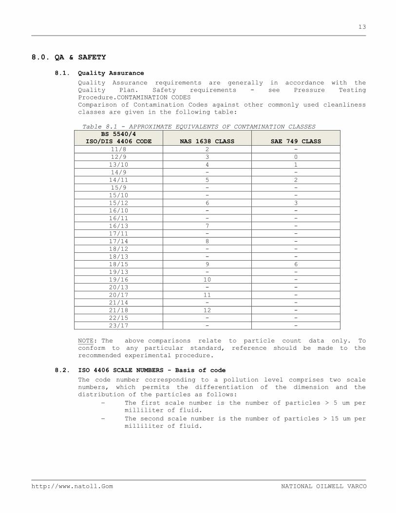
Comparison of Contamination Codes against other commonly used cleanliness
classes are given in the following table:
Table 8.1 - APPROXIMATE EQUIVALENTS OF CONTAMINATION CLASSES
BS 5540/4
ISO/DIS 4406 CODE NAS 1638 CLASS SAE 749 CLASS
11/8 2 -
12/9 3 0
13/10 4 1
14/9 - -
14/11 5 2
15/9 - -
15/10 - -
15/12 6 3
16/10 - -
16/11 - -
16/13 7 -
17/11 - -
17/14 8 -
18/12 - -
18/13 - -
18/15 9 6
19/13 - -
19/16 10 -
20/13 - -
20/17 11 -
21/14 - -
21/18 12 -
22/15 - -
23/17 - -
NOTE: The above comparisons relate to particle count data only. To
conform to any particular standard, reference should be made to the
recommended experimental procedure.
8.2. ISO 4406 SCALE NUMBERS - Basis of code
The code number corresponding to a pollution level comprises two scale
numbers, which permits the differentiation of the dimension and the
distribution of the particles as follows:
The first scale number is the number of particles > 5 um per
milliliter of fluid.
The second scale number is the number of particles > 15 um per
milliliter of fluid.

14
http://www.natoll.Gom NATIONAL OILWELL VARCO
Allocation of scale numbers:
The scale numbers are attributed according to the number of particles
counted large than um and 15 um respectively, yielded in 1 ml. of fluid
(see the table).
Number of particles per milliliter Scale
number More than Up to and including
80 000 160 000 24
40 000 80 000 23
20 000 40 000 22
10 000 20 000 21
5 000 10 000 20
2 500 5 000 19
1 300 2 500 18
640 1 300 17
320 640 16
160 320 15
80 160 14
40 80 13
20 40 12
10 20 11
5 10 10
2,5 5 9
1,3 2,5 8
9.0. COMPLETION RECORD SHEET EXAMPLE
Note: This completion record sheet and Hydraulic Block Diagram with the flushing
loop marked and the result of the oil sample must be stored in a flushing record
book as a final documentation of the flushing.


