TECHNICAL DATASHEET Safety and function tester data_GLP2-BASIC_Rev3.4.pdfTECHNICAL DATASHEET ....
9
SCHLEICH GmbH - An der Schleuse 11 - 58675 Hemer - Germany - 0049 (0)2372 94989498 - [email protected] - www.schleich.com Page 1 of 9 TECHNICAL DATASHEET Safety and function tester GLP2-BASIC Revision 3.4 / valid from January 2015 Standard model ELECTRICAL SPECIFICATION Supply voltage 110-250 V AC Mains frequency 47-63 Hz No load current consumption 0.5 A, fuse T10A GENERAL SPECIFICATION Display 7“- color graphic display, resolution 800 x 480 pixels, display behind scratch-proof glass Data input PCAP capacitive touch display behind scratch-proof glass Time & Date clock with integrated calendar Test plan storage 10,000 test plans Test result storage 250,000 test results Test connections test socket 1) on the front panel of the testers test probe connection on the rear side of the tester industrial plug connection 1,2) on the rear side of the tester high-voltage sockets on the rear side of the tester Safety key lock 3) access to the test parameters protected by password 2 x Interlock-safety inputs HV, dual-circuit according CAT IV, internal relays with positively driven contacts 2 x Interlock- safety inputs NV, dual-circuit according CAT IV, internal relays with positively driven contacts input for emergency stop CE-conform, corresponding to VDE 0104 / EN 61010 Interface (display) HDMI port to operate an additional, large monitor screen / HDMI 1.0 800x480 and/or 800x600 Interfaces (communication) 2 x USB on the front side of the tester 4 x USB on the rear side of the tester LAN on the rear side of the tester RS232 on the rear side of the tester Interfaces (standard) outputs : result light, warning light inputs : foot-switch on the rear side of the tester, two-hand start, control plug Interface (PLC-I/O-remote control) outputs : GO / NO GO, test is running, ready, HV on, I>min, disruptive discharge 16 x freely configurable outputs inputs : start, stop, foot-switch, 4 x freely configurable inputs Calibration by software, without opening up the tester Software operator convenience All inputs are checked by plausibility check. Therefore, wrong inputs should be avoided. The operator can display a detailed help text for any input option. Operation languages DE, US Software languages DE, US, IT, ES, FR Design and production Made in Germany – True German Quality MECHANICAL SPECIFICATION Variants ▪ desktop device , ergonomically designed, optionally available with a 3-stage slewable front panel ▪ desktop device in 19“-design incl. solid pedestals to put the tester into an inclined position ▪ rack-mount device : optional mounting kit for installation in a 19“-cabinet Working environment working temperature 0° - 50° C / 32° - 104° F, designed for a relative humidity of 0 - 80%rF without condensation! Storage storage temperature -10° - 60° C / 14° - 140° F, designed for a relative humidity of 0 - 90%rF without condensation!
Transcript of TECHNICAL DATASHEET Safety and function tester data_GLP2-BASIC_Rev3.4.pdfTECHNICAL DATASHEET ....
SCHLEICH GmbH - An der Schleuse 11 - 58675 Hemer - Germany - 0049 (0)2372 94989498 - [email protected] - www.schleich.com Page 1 of 9
TECHNICAL DATASHEET
Safety and function tester
GLP2-BASIC Revision 3.4 / valid from January 2015
Standard model ELECTRICAL SPECIFICATION Supply voltage 110-250 V AC
Mains frequency 47-63 Hz No load current consumption 0.5 A, fuse T10A
GENERAL SPECIFICATION Display 7“- color graphic display, resolution 800 x 480 pixels, display behind scratch-proof glass Data input PCAP capacitive touch display behind scratch-proof glass
Time & Date clock with integrated calendar Test plan storage 10,000 test plans
Test result storage 250,000 test results Test connections test socket1) on the front panel of the testers
test probe connection on the rear side of the tester industrial plug connection 1,2) on the rear side of the tester high-voltage sockets on the rear side of the tester
Safety key lock3) access to the test parameters protected by password 2 x Interlock-safety inputs HV, dual-circuit according CAT IV, internal relays with positively driven contacts 2 x Interlock- safety inputs NV, dual-circuit according CAT IV, internal relays with positively driven contacts input for emergency stop CE-conform, corresponding to VDE 0104 / EN 61010
Interface (display) HDMI port to operate an additional, large monitor screen / HDMI 1.0 800x480 and/or 800x600
Interfaces (communication) 2 x USB on the front side of the tester 4 x USB on the rear side of the tester LAN on the rear side of the tester RS232 on the rear side of the tester
Interfaces (standard) outputs : result light, warning light inputs : foot-switch on the rear side of the tester, two-hand start, control plug
Interface (PLC-I/O-remote control) outputs : GO / NO GO, test is running, ready, HV on, I>min, disruptive discharge 16 x freely configurable outputs inputs : start, stop, foot-switch, 4 x freely configurable inputs
Calibration by software, without opening up the tester
Software operator convenience All inputs are checked by plausibility check. Therefore, wrong inputs should be avoided. The operator can display a detailed help text for any input option.
Operation languages DE, US Software languages DE, US, IT, ES, FR Design and production Made in Germany – True German Quality
MECHANICAL SPECIFICATION Variants ▪ desktop device , ergonomically designed, optionally available with a 3-stage slewable front panel
▪ desktop device in 19“-design incl. solid pedestals to put the tester into an inclined position▪ rack-mount device : optional mounting kit for installation in a 19“-cabinet
Working environment working temperature 0° - 50° C / 32° - 104° F, designed for a relative humidity of 0 - 80%rF without condensation!
Storage storage temperature -10° - 60° C / 14° - 140° F, designed for a relative humidity of 0 - 90%rF without condensation!
SCHLEICH GmbH - An der Schleuse 11 - 58675 Hemer - Germany - 0049 (0)2372 94989498 - [email protected] - www.schleich.com Page 2 of 9
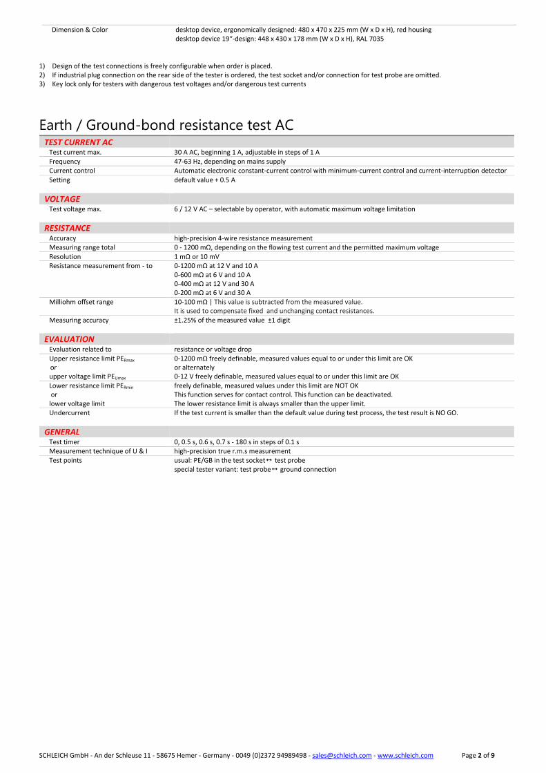
Dimension & Color desktop device, ergonomically designed: 480 x 470 x 225 mm (W x D x H), red housing desktop device 19“-design: 448 x 430 x 178 mm (W x D x H), RAL 7035
1) Design of the test connections is freely configurable when order is placed.2) If industrial plug connection on the rear side of the tester is ordered, the test socket and/or connection for test probe are omitted.3) Key lock only for testers with dangerous test voltages and/or dangerous test currents
Earth / Ground-bond resistance test AC TEST CURRENT AC Test current max. 30 A AC, beginning 1 A, adjustable in steps of 1 A
Frequency 47-63 Hz, depending on mains supply Current control Automatic electronic constant-current control with minimum-current control and current-interruption detector
Setting default value + 0.5 A
VOLTAGE Test voltage max. 6 / 12 V AC – selectable by operator, with automatic maximum voltage limitation
RESISTANCE Accuracy high-precision 4-wire resistance measurement Measuring range total 0 - 1200 mΩ, depending on the flowing test current and the permitted maximum voltage
Resolution 1 mΩ or 10 mV Resistance measurement from - to 0-1200 mΩ at 12 V and 10 A
0-600 mΩ at 6 V and 10 A 0-400 mΩ at 12 V and 30 A 0-200 mΩ at 6 V and 30 A
Milliohm offset range 10-100 mΩ | This value is subtracted from the measured value. It is used to compensate fixed and unchanging contact resistances.
Measuring accuracy ±1.25% of the measured value ±1 digit
EVALUATION Evaluation related to resistance or voltage drop
Upper resistance limit PERmax
or upper voltage limit PEUmax
0-1200 mΩ freely definable, measured values equal to or under this limit are OK or alternately 0-12 V freely definable, measured values equal to or under this limit are OK
Lower resistance limit PERmin or lower voltage limit
freely definable, measured values under this limit are NOT OK This function serves for contact control. This function can be deactivated. The lower resistance limit is always smaller than the upper limit.
Undercurrent If the test current is smaller than the default value during test process, the test result is NO GO.
GENERAL Test timer 0, 0.5 s, 0.6 s, 0.7 s - 180 s in steps of 0.1 s Measurement technique of U & I high-precision true r.m.s measurement Test points usual: PE/GB in the test socket test probe
special tester variant: test probe ground connection
SCHLEICH GmbH - An der Schleuse 11 - 58675 Hemer - Germany - 0049 (0)2372 94989498 - [email protected] - www.schleich.com Page 3 of 9
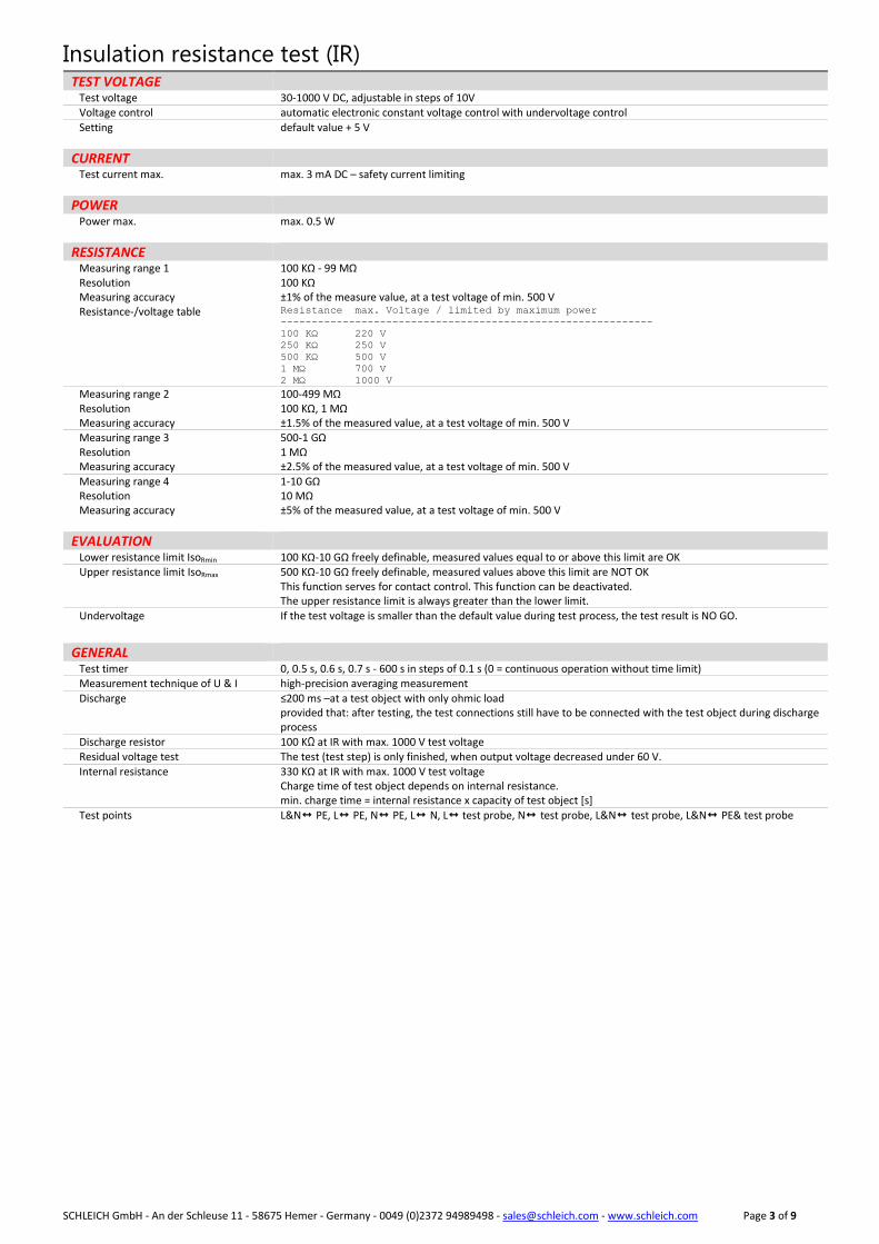
Insulation resistance test (IR) TEST VOLTAGE Test voltage 30-1000 V DC, adjustable in steps of 10V Voltage control automatic electronic constant voltage control with undervoltage control
Setting default value + 5 V
CURRENT Test current max. max. 3 mA DC – safety current limiting
POWER Power max. max. 0.5 W
RESISTANCE Measuring range 1 Resolution Measuring accuracy Resistance-/voltage table
100 KΩ - 99 MΩ 100 KΩ ±1% of the measure value, at a test voltage of min. 500 V Resistance max. Voltage / limited by maximum power
------------------------------------------------------------
100 KΩ 220 V
250 KΩ 250 V
500 KΩ 500 V
1 MΩ 700 V
2 MΩ 1000 V
Measuring range 2 Resolution Measuring accuracy
100-499 MΩ 100 KΩ, 1 MΩ ±1.5% of the measured value, at a test voltage of min. 500 V
Measuring range 3 Resolution Measuring accuracy
500-1 GΩ 1 MΩ ±2.5% of the measured value, at a test voltage of min. 500 V
Measuring range 4 Resolution Measuring accuracy
1-10 GΩ 10 MΩ ±5% of the measured value, at a test voltage of min. 500 V
EVALUATION Lower resistance limit IsoRmin 100 KΩ-10 GΩ freely definable, measured values equal to or above this limit are OK Upper resistance limit IsoRmax 500 KΩ-10 GΩ freely definable, measured values above this limit are NOT OK
This function serves for contact control. This function can be deactivated. The upper resistance limit is always greater than the lower limit.
Undervoltage If the test voltage is smaller than the default value during test process, the test result is NO GO.
GENERAL Test timer 0, 0.5 s, 0.6 s, 0.7 s - 600 s in steps of 0.1 s (0 = continuous operation without time limit) Measurement technique of U & I high-precision averaging measurement
Discharge ≤200 ms –at a test object with only ohmic load provided that: after testing, the test connections still have to be connected with the test object during discharge process
Discharge resistor 100 KΩ at IR with max. 1000 V test voltage Residual voltage test The test (test step) is only finished, when output voltage decreased under 60 V.
Internal resistance 330 KΩ at IR with max. 1000 V test voltage Charge time of test object depends on internal resistance. min. charge time = internal resistance x capacity of test object [s]
Test points L&N PE, L PE, N PE, L N, L test probe, N test probe, L&N test probe, L&N PE& test probe
Page 4 of 9
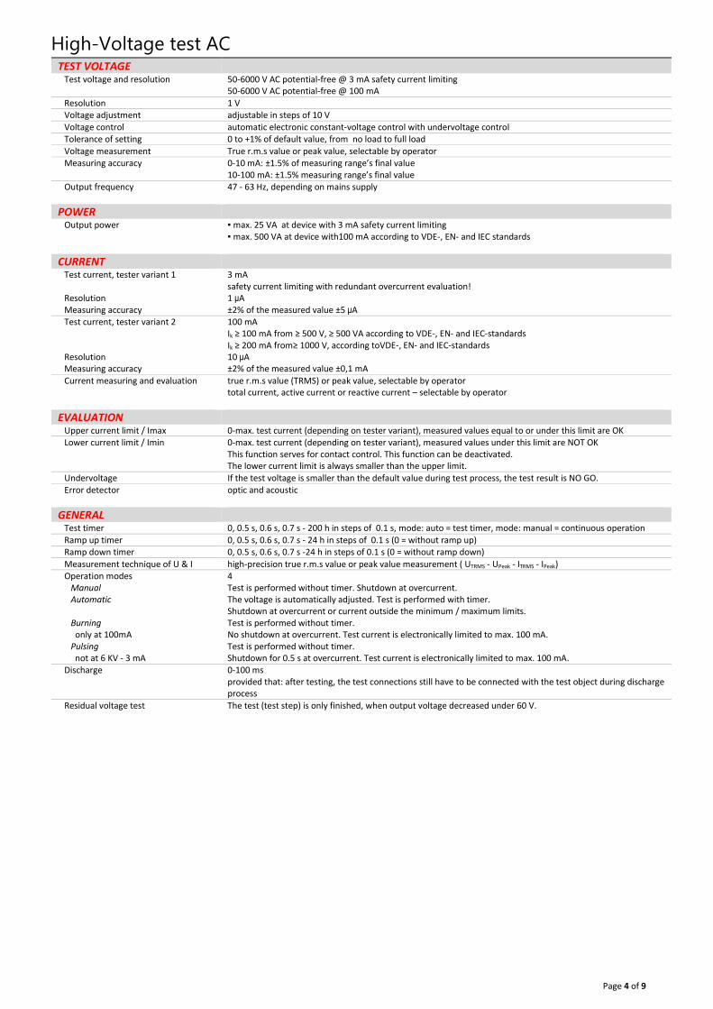
High-Voltage test AC TEST VOLTAGE Test voltage and resolution 50-6000 V AC potential-free @ 3 mA safety current limiting
50-6000 V AC potential-free @ 100 mA
Resolution 1 V Voltage adjustment adjustable in steps of 10 V
Voltage control automatic electronic constant-voltage control with undervoltage control Tolerance of setting 0 to +1% of default value, from no load to full load
Voltage measurement True r.m.s value or peak value, selectable by operator Measuring accuracy 0-10 mA: ±1.5% of measuring range’s final value
10-100 mA: ±1.5% measuring range’s final value Output frequency 47 - 63 Hz, depending on mains supply
POWER Output power ▪ max. 25 VA at device with 3 mA safety current limiting
▪ max. 500 VA at device with100 mA according to VDE-, EN- and IEC standards
CURRENT Test current, tester variant 1
Resolution Measuring accuracy
3 mA safety current limiting with redundant overcurrent evaluation! 1 μA
±2% of the measured value ±5 μA Test current, tester variant 2
Resolution Measuring accuracy
100 mA Ik ≥ 100 mA from ≥ 500 V, ≥ 500 VA according to VDE-, EN- and IEC-standards Ik ≥ 200 mA from≥ 1000 V, according toVDE-, EN- and IEC-standards
10 μA
±2% of the measured value ±0,1 mA
Current measuring and evaluation true r.m.s value (TRMS) or peak value, selectable by operator total current, active current or reactive current – selectable by operator
EVALUATION Upper current limit / Imax 0-max. test current (depending on tester variant), measured values equal to or under this limit are OK Lower current limit / Imin 0-max. test current (depending on tester variant), measured values under this limit are NOT OK
This function serves for contact control. This function can be deactivated. The lower current limit is always smaller than the upper limit.
Undervoltage If the test voltage is smaller than the default value during test process, the test result is NO GO. Error detector optic and acoustic
GENERAL Test timer 0, 0.5 s, 0.6 s, 0.7 s - 200 h in steps of 0.1 s, mode: auto = test timer, mode: manual = continuous operation
Ramp up timer 0, 0.5 s, 0.6 s, 0.7 s - 24 h in steps of 0.1 s (0 = without ramp up) Ramp down timer 0, 0.5 s, 0.6 s, 0.7 s -24 h in steps of 0.1 s (0 = without ramp down)
Measurement technique of U & I high-precision true r.m.s value or peak value measurement ( UTRMS - UPeak - ITRMS - IPeak) Operation modes Manual Automatic
Burning only at 100mA Pulsing not at 6 KV - 3 mA
4 Test is performed without timer. Shutdown at overcurrent. The voltage is automatically adjusted. Test is performed with timer. Shutdown at overcurrent or current outside the minimum / maximum limits. Test is performed without timer. No shutdown at overcurrent. Test current is electronically limited to max. 100 mA. Test is performed without timer. Shutdown for 0.5 s at overcurrent. Test current is electronically limited to max. 100 mA.
Discharge 0-100 ms provided that: after testing, the test connections still have to be connected with the test object during discharge process
Residual voltage test The test (test step) is only finished, when output voltage decreased under 60 V.
Page 5 of 9
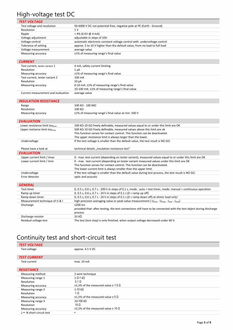
High-voltage test DC TEST VOLTAGE Test voltage and resolution 50-6000 V DC not potential-free, negative pole at PE (Earth - Ground) Resolution 1 V
Ripple < 4% (6 KV @ 4 mA) Voltage adjustment adjustable in steps of 10V
Voltage control automatic electronic constant voltage control with undervoltage control Tolerance of setting approx. 5 to 10 V higher than the default value, from no load to full load
Voltage measurement average value Measuring accuracy ±1% of measuring range’s final value
CURRENT Test current, tester variant 1 Resolution Measuring accuracy
4 mA, safety current limiting
1 μA
±1% of measuring range’s final value
Test current, tester variant 2 Resolution Measuring accuracy
100 mA
10 μA
0-10 mA: ±1% of measuring range’s final value 10-100 mA: ±1% of measuring range’s final value
Current measurement and evaluation average value
INSULATION RESISTANCE Range Resolution Measuring accuracy
100 KΩ - 100 MΩ 100 KΩ ±1% of measuring range’s final value at min. 500 V
EVALUATION Lower resistance limit IsoRmin 100 KΩ-10 GΩ freely definable, measured values equal to or under this limit are OK
Upper restiance limit IsoRmax 500 KΩ-10 GΩ freely definable, measured values above this limit are ok This function serves for contact control. This function can be deactivated. The upper resistance limit is always larger than the lower.
Undervoltage If the test voltage is smaller than the default value, the test result is NO GO.
Please have a look at technical details „Insulation resistance test“
EVALUATION Upper current limit / Imax 0 - max. test current (depending on tester variant), measured values equal to or under this limit are OK Lower current limit / Imin 0 - max. test current (depending on tester variant measured values under this limit are OK
This function serves for contact control. This function can be deactivated. The lower current limit is always smaller than the upper limit.
Undervoltage If the test voltage is smaller than the default value during test process, the test result is NO GO. Error detector optic and acoustic
GENERAL Test timer 0, 0.5 s, 0.6 s, 0.7 s - 200 h in steps of 0.1 s, mode : auto = test timer, mode: manual = continuous operation
Ramp up timer 0, 0.5 s, 0.6 s, 0.7 s - 24 h in steps of 0.1 s (0 = ramp up off) Ramp down timer 0, 0.5 s, 0.6 s, 0.7 s - 24 h in steps of 0.1 s (0 = ramp down off) at ohmic load only!
Measurement technique of U & I high-precision averaging value or peak value measurement ( UAVG - UPeak - IAVG - IPeak) Discharge ≤200 ms
provided that: after testing, the test connections still have to be connected with the test object during discharge process
Discharge resistor 33 KΩ Residual voltage test The test (test step) is only finished, when output voltage decreased under 60 V.
Continuity test and short-circuit test TEST VOLTAGE Test voltage approx. 4.5 V DC
TEST CURRENT Test current max. 10 mA
RESISTANCE Measuring method 2-wire technique
Measuring range 1 Resolution Measuring accuracy
1 Ω-1 kΩ
0,1 Ω
±1,5% of the measured value ± 1.5 Ω
Measuring range 2 Resolution Measuring accuracy
1-10 kΩ
1 Ω
±1,5% of the measured value ± 5 Ω
Measuring range 3 Resolution Measuring accuracy
10-100 kΩ
10 Ω ±2,5% of the measured value ± 10 Ω
L N short-circuit test ▪

Page 6 of 9
EVALUATION Upper & lower Limit ±tolerance in % of default value
resistances within the tolerance limits are OK
Upper limit resistances under this limit are OK
Lower limit resistances above this limit are OK
Page 7 of 9
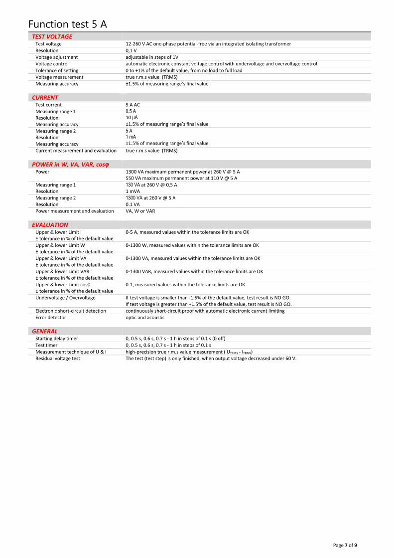
Function test 5 A TEST VOLTAGE Test voltage 12-260 V AC one-phase potential-free via an integrated isolating transformer Resolution 0,1 V
Voltage adjustment adjustable in steps of 1V Voltage control automatic electronic constant voltage control with undervoltage and overvoltage control
Tolerance of setting 0 to +1% of the default value, from no load to full load Voltage measurement true r.m.s value (TRMS)
Measuring accuracy ±1.5% of measuring range’s final value
CURRENT Test current 5 A AC
Measuring range 1 Resolution Measuring accuracy
0.5 A 10 μA
±1.5% of measuring range’s final value
Measuring range 2 Resolution Measuring accuracy
5 A 1 mA
±1.5% of measuring range’s final value
Current measurement and evaluation true r.m.s value (TRMS)
POWER in W, VA, VAR, cosφ Power 1300 VA maximum permanent power at 260 V @ 5 A
550 VA maximum permanent power at 110 V @ 5 A
Measuring range 1 Resolution
130 VA at 260 V @ 0.5 A
1 mVA Measuring range 2 Resolution
1300 VA at 260 V @ 5 A
0.1 VA Power measurement and evaluation VA, W or VAR
EVALUATION Upper & lower Limit I ± tolerance in % of the default value
0-5 A, measured values within the tolerance limits are OK
Upper & lower Limit W ± tolerance in % of the default value
0-1300 W, measured values within the tolerance limits are OK
Upper & lower Limit VA ± tolerance in % of the default value
0-1300 VA, measured values within the tolerance limits are OK
Upper & lower Limit VAR ± tolerance in % of the default value
0-1300 VAR, measured values within the tolerance limits are OK
Upper & lower Limit cosφ ± tolerance in % of the default value
0-1, measured values within the tolerance limits are OK
Undervoltage / Overvoltage If test voltage is smaller than -1.5% of the default value, test result is NO GO. If test voltage is greater than +1.5% of the default value, test result is NO GO.
Electronic short-circuit detection continuously short-circuit proof with automatic electronic current limiting Error detector optic and acoustic
GENERAL Starting delay timer 0, 0.5 s, 0.6 s, 0.7 s - 1 h in steps of 0.1 s (0 off) Test timer 0, 0.5 s, 0.6 s, 0.7 s - 1 h in steps of 0.1 s
Measurement technique of U & I high-precision true r.m.s value measurement ( UTRMS - ITRMS) Residual voltage test The test (test step) is only finished, when output voltage decreased under 60 V.

Page 8 of 9
Function test 16 A TEST VOLTAGE Test voltage 16 A tester: 0 - 260 V AC one-phase, externally supplied via separate connection Resolution 0,1 V
Voltage adjustment Voltage adjustment not possible Voltage control externally controlled and supplied
with undervoltage and overvoltage control Tolerance of setting No voltage setting
Voltage measurement true r.m.s value (TRMS) Measuring accuracy ±1.5% of measuring range’s final value
CURRENT Test current 16 A AC Resolution 1 mA
Current measurement and evaluation true r.m.s value (TRMS) Measuring accuracy 16 A tester: ±1.5% measuring range’s final value
POWER W, VA, VAR, cosφ Power 4200 W, 4200 VA, 4200 VAR maximum permanent power bei 260 V @ 16 A Resolution 1 VA, 1 W, 1 VAR Power measurement and evaluation VA, W or VAR
EVALUATION Upper & lower limit I ± tolerance in % of the default value
0-16 A, measured values within the tolerance limits are OK
Upper & lower limit W ± tolerance in % of the default value
0-4200 W, measured values within the tolerance limits are OK
Upper & lower limit VA ± tolerance in % of the default value
0-4200 VA, measured values within the tolerance limits are OK
Upper & lower limit VAR ± tolerance in % of the default value
0-4200 VAR, measured values within the tolerance limits are OK
Upper & lower limit cosφ ± tolerance in % of the default value
0-1, measured values within the tolerance limits are OK
Undervoltage / Overvoltage If test voltage is smaller than -1.5% of the default value, test result is NO GO. If test voltage is greater than +1.5% of the default value, test result is NO GO.
Electronic short-circuit detection no electronic fuse, fuse protection via 2 MCBs Error detector optic and acoustic
GENERAL Starting delay timer 0, 0.5 s, 0.6 s, 0.7 s - 200 h in steps of 0.1 s (0 = off) Test timer 0, 0.5 s, 0.6 s, 0.7 s- 200 h in steps of 0.1 s
Measurement technique U & I high-precision true r.m.s. measurement ( UTRMS - ITRMS) Residual voltage test The test (test step) is only finished, when output voltage decreased under 60 V.
Page 9 of 9
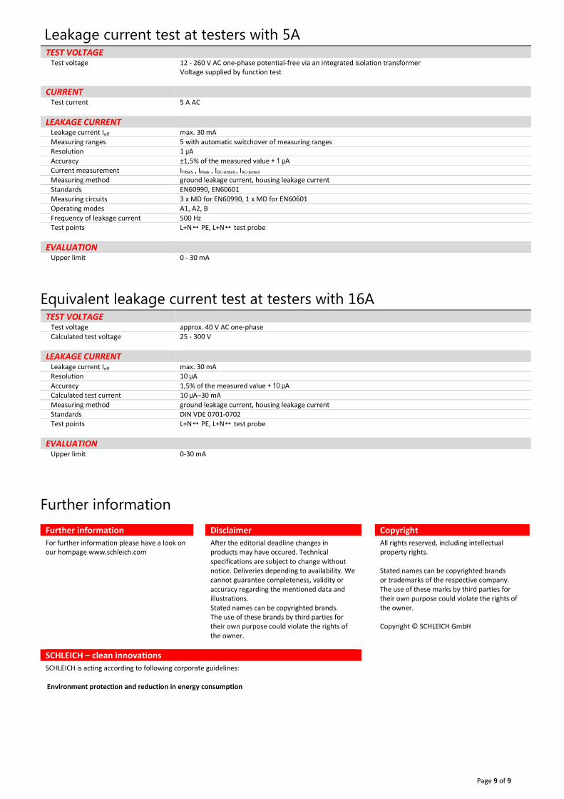
Leakage current test at testers with 5A TEST VOLTAGE Test voltage 12 - 260 V AC one-phase potential-free via an integrated isolation transformer
Voltage supplied by function test
CURRENT Test current 5 A AC
LEAKAGE CURRENT Leakage current Ieff max. 30 mA
Measuring ranges 5 with automatic switchover of measuring ranges Resolution 1 μA
Accuracy ±1,5% of the measured value + 1 μA Current measurement ITRMS , IPeak , IDC-Anteil , IAC-Anteil
Measuring method ground leakage current, housing leakage current Standards EN60990, EN60601
Measuring circuits 3 x MD for EN60990, 1 x MD for EN60601 Operating modes A1, A2, B
Frequency of leakage current 500 Hz Test points L+N PE, L+N test probe
EVALUATION Upper limit 0 - 30 mA
Equivalent leakage current test at testers with 16A TEST VOLTAGE Test voltage approx. 40 V AC one-phase Calculated test voltage 25 - 300 V
LEAKAGE CURRENT Leakage current Ieff max. 30 mA Resolution 10 μA
Accuracy 1,5% of the measured value + 10 μA Calculated test current 10 μA–30 mA
Measuring method ground leakage current, housing leakage current Standards DIN VDE 0701-0702 Test points L+N PE, L+N test probe
EVALUATION Upper limit 0-30 mA
Further information
Further information Disclaimer Copyright
For further information please have a look on our hompage www.schleich.com
After the editorial deadline changes in products may have occured. Technical specifications are subject to change without notice. Deliveries depending to availability. We cannot guarantee completeness, validity or accuracy regarding the mentioned data and illustrations. Stated names can be copyrighted brands. The use of these brands by third parties for their own purpose could violate the rights of the owner.
All rights reserved, including intellectual property rights.
Stated names can be copyrighted brands or trademarks of the respective company. The use of these marks by third parties for their own purpose could violate the rights of the owner.
Copyright © SCHLEICH GmbH
SCHLEICH – clean innovations
SCHLEICH is acting according to following corporate guidelines:
Environment protection and reduction in energy consumption