Technical Data Sheet - Home - Steffes
4
Technical Data Sheet 5100 Comfort Plus Hydronic 5-Year Limited Manufacturer’s Warranty Steffes | 3050 Highway 22 North | Dickinson, North Dakota 58601-9413 | 701-483-5400 Rev 4 • System will fit through a 30” doorway without disassembling. For smaller openings or for ease in moving, it can be disassembled. Placement and Clearances • The area in which the system is installed must remain free of debris and adequate ventilation is required to maintain room temperature of less than 85° F. A static heat recovery unit or air handler are options available to move the radiant heat from the outer panels to a more desirable area. • Adhere to all national and local electrical and building code placement requirements for electric heating appliances. • An 18” high stand is available from the factory to elevate the system if necessary. • Bottom = 1 inch clearance • Top = 6 inches (from combustible material) • Front = 36 inches (for ease in servicing) • Left Side = 36 inches (for ease in servicing) • Back and Right Side = 3 inches (from combustible material) Unit Dimensions • The breakers on the Comfort Plus are intend- ed for service disconnect only. The 15 amp breaker powers the pump, blowers and system controls circuit. The 60 amp breakers power the element circuits. • Factory configured with multiple circuit, single phase connections. If single feed is desired a single feed kit is available from the factory. Phase balancing is recommended when mak- ing connections in 3-phase applications. • Controls circuit MUST include a neutral wire. Line Voltage Field Connections and Circuit Phasing
Transcript of Technical Data Sheet - Home - Steffes

Technical Data Sheet5100 Comfort Plus Hydronic
5-Year Limited Manufacturer’s Warranty
Steffes | 3050 Highway 22 North | Dickinson, North Dakota 58601-9413 | 701-483-5400 Rev 4
• System will fit through a 30” doorway without disassembling. For smaller openings or for ease in moving, it can be disassembled.
Placement and Clearances• The area in which the system is installed must
remain free of debris and adequate ventilation is required to maintain room temperature of less than 85° F. A static heat recovery unit or air handler are options available to move the radiant heat from the outer panels to a more desirable area.
• Adhere to all national and local electrical and building code placement requirements for electric heating appliances.
• An 18” high stand is available from the factory to elevate the system if necessary.
• Bottom = 1 inch clearance• Top = 6 inches (from combustible material)• Front = 36 inches (for ease in servicing)• Left Side = 36 inches (for ease in servicing)• Back and Right Side = 3 inches (from combustible material)
Unit Dimensions
• The breakers on the Comfort Plus are intend-ed for service disconnect only. The 15 amp breaker powers the pump, blowers and system controls circuit. The 60 amp breakers power the element circuits.
• Factory configured with multiple circuit, single phase connections. If single feed is desired a single feed kit is available from the factory. Phase balancing is recommended when mak-ing connections in 3-phase applications.
• Controls circuit MUST include a neutral wire.
Line Voltage Field Connections and Circuit Phasing

Steffes | 3050 Highway 22 North | Dickinson, North Dakota 58601-9413 | 701-483-5400 Rev 4
Low Voltage Peak Control ConnectionsIf using the optional Steffes Power Line Carrier Transceiver or Steffes Time Clock Module for peak control, the direct wiring shown here is not necessary.
Typical System PlumbingThere are many ways to connect plumbing and regulate temperature of water supplied from the primary loop. These are typical plumbing schematics.
Low Voltage Terminal Block CodingRP = Peak Control Input CommonP = Peak Control InputAP = Anticipated Peak (Pre-Peak) Control InputCOM = Peak Control Output CommonNC = Peak Control Output (Normally Closed)NO = Peak Control Output (Normally Open)
Single Temperature Zone
Air Handler Applications
Pressure Drop Through Heat Exchanger
STATIC PRESSURE (Feet Water Column)
Based on 80 degree entry water temperature with a
50% glycol mix.
.1 ft @ 2 GMP
.2 ft @ 4 GMP.4 ft @6 GMP.7 ft @ 8 GMP
1.1 ft @10 GMP
Typical Floor Zone Design
Pipe Size
Maximum Pipe Length
3/8” 200’1/2” 300’5/8” 500’
Pipe length will vary by manufacturer.
Primary Water Loop Plumbing• The system must be plumbed with a primary
water loop consisting of a minimum of 10’ of 1” pipe and its own circulator pump (Grundfos UP15-42F single speed 115 VAC or equal recom-mended). The primary loop serves to regulate heat transfer from the system’s heat exchanger. A kit containing components generally installed with hydronic heat systems is available from Steffes. The primary loop must be powered by the Comfort Plus control system.
• The Comfort Plus Hydronic system is factory configured for left side plumbing attachment only.
Steffes | 3050 Highway 22 North | Dickinson, North Dakota 58601-9413 | 701-483-5400 Rev 4Rev 4
Low Voltage Wall Thermostat, Sensor, and Compressor Connections• 24 VAC wall thermostat must be used. Honeywell brands shown in schematics and recommended.• A digital wall thermostat is recommended for use with Comfort Plus systems. If utilizing a mechan-
ical wall thermostat, it may be necessary to add a load resistor (250 ohm, 5 watt) due to the low current draw (.01 amp) on the heat call input circuit.
• An outdoor sensor is included with the system to provide outdoor temperatures for automatic charge control (regulation of stored heat).
Single Hydronic Heating Zone Application
STATIC PRESSURE (Feet Water Column)
Based on 80 degree entry water temperature with a
50% glycol mix.
.1 ft @ 2 GMP
.2 ft @ 4 GMP.4 ft @6 GMP.7 ft @ 8 GMP
1.1 ft @10 GMPTerminal Block Code Designations
W/AUXY1Y2GO
H/ERC
Y12Y22O2
Outdoor
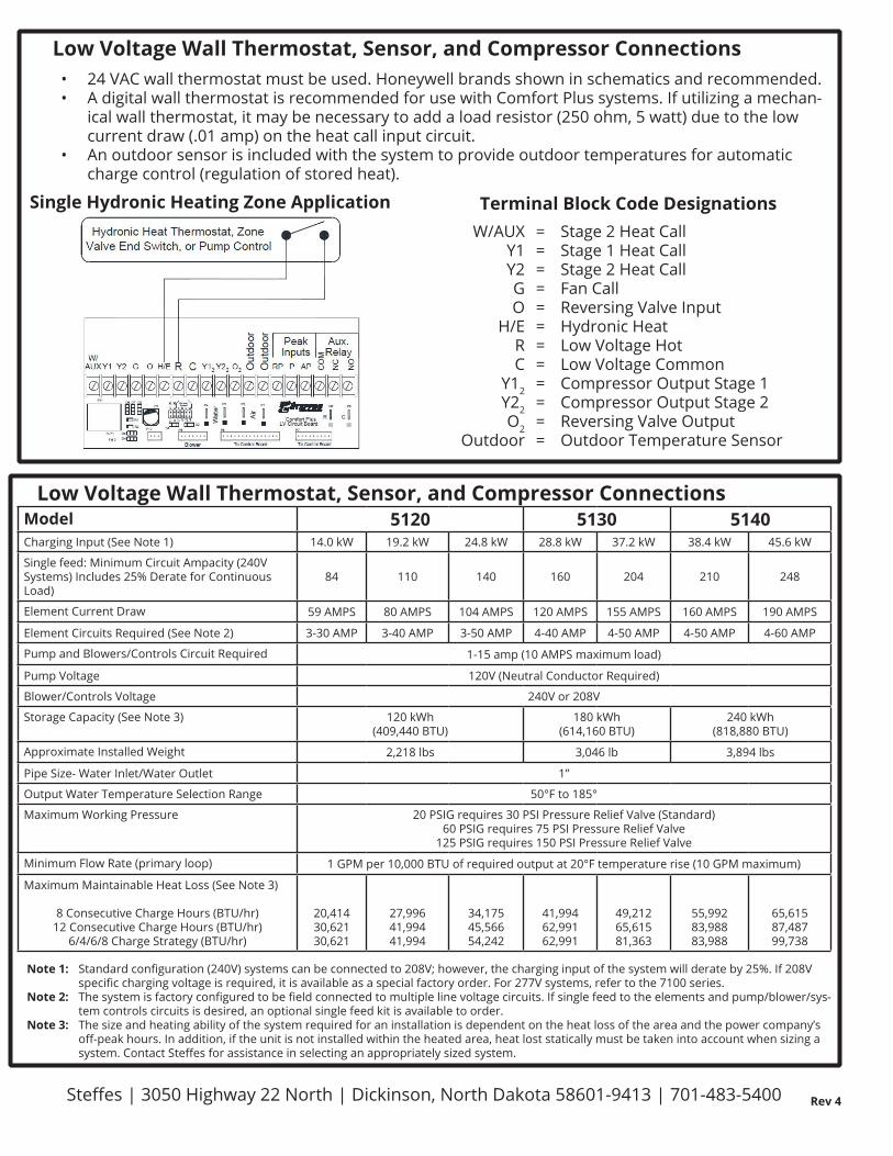
Low Voltage Wall Thermostat, Sensor, and Compressor ConnectionsModel 5120 5130 5140Charging Input (See Note 1) 14.0 kW 19.2 kW 24.8 kW 28.8 kW 37.2 kW 38.4 kW 45.6 kW
Single feed: Minimum Circuit Ampacity (240V Systems) Includes 25% Derate for Continuous Load)
84 110 140 160 204 210 248
Element Current Draw 59 AMPS 80 AMPS 104 AMPS 120 AMPS 155 AMPS 160 AMPS 190 AMPS
Element Circuits Required (See Note 2) 3-30 AMP 3-40 AMP 3-50 AMP 4-40 AMP 4-50 AMP 4-50 AMP 4-60 AMP
Pump and Blowers/Controls Circuit Required 1-15 amp (10 AMPS maximum load)
Pump Voltage 120V (Neutral Conductor Required)
Blower/Controls Voltage 240V or 208V
Storage Capacity (See Note 3) 120 kWh(409,440 BTU)
180 kWh(614,160 BTU)
240 kWh(818,880 BTU)
Approximate Installed Weight 2,218 lbs 3,046 lb 3,894 lbs
Pipe Size- Water Inlet/Water Outlet 1”
Output Water Temperature Selection Range 50°F to 185°
Maximum Working Pressure 20 PSIG requires 30 PSI Pressure Relief Valve (Standard)60 PSIG requires 75 PSI Pressure Relief Valve
125 PSIG requires 150 PSI Pressure Relief Valve
Minimum Flow Rate (primary loop) 1 GPM per 10,000 BTU of required output at 20°F temperature rise (10 GPM maximum)
Maximum Maintainable Heat Loss (See Note 3)
8 Consecutive Charge Hours (BTU/hr)12 Consecutive Charge Hours (BTU/hr)
6/4/6/8 Charge Strategy (BTU/hr)
20,41430,62130,621
27,99641,99441,994
34,17545,56654,242
41,99462,99162,991
49,21265,61581,363
55,99283,98883,988
65,61587,48799,738
Note 1: Standard configuration (240V) systems can be connected to 208V; however, the charging input of the system will derate by 25%. If 208V specific charging voltage is required, it is available as a special factory order. For 277V systems, refer to the 7100 series.
Note 2: The system is factory configured to be field connected to multiple line voltage circuits. If single feed to the elements and pump/blower/sys-tem controls circuits is desired, an optional single feed kit is available to order.
Note 3: The size and heating ability of the system required for an installation is dependent on the heat loss of the area and the power company’s off-peak hours. In addition, if the unit is not installed within the heated area, heat lost statically must be taken into account when sizing a system. Contact Steffes for assistance in selecting an appropriately sized system.
============
Stage 2 Heat CallStage 1 Heat CallStage 2 Heat CallFan CallReversing Valve InputHydronic HeatLow Voltage HotLow Voltage CommonCompressor Output Stage 1Compressor Output Stage 2 Reversing Valve OutputOutdoor Temperature Sensor

Steffes | 3050 Highway 22 North | Dickinson, North Dakota 58601-9413 | 701-483-5400 Rev 4
Optional Steffes Air HandlerThe Steffes Air Handler is an optional device designed to interface with the Comfort Plus Hydronic (5100 Series) furnace to allow it to provide forced air heating as a stand alone furnace or as a supplement to other ducted heating systems such as a heat pump. When used with a heat pump, it allows the Comfort Plus Hydronic furnace to serve as the back-up heat source and provide comfort modulation. Heat pumps can be operated to much lower temperatures allowing for full utilization of their efficiency while optimizing system performance. A duct sensor constantly monitors outlet air temperature and modulates the precise amount of stored off-peak heat needed to eliminate uncomfortable discharge air temperatures typically associated with heat pump systems during cool outdoor temperatures. The air handler will also direct the heat lost statically through the furnace’s outer panels into the ductwork for delivery to the living space (automatic static heat recovery). The internal controls of the Comfort Plus Hydronic furnace automatically regulate the operation of the air handler. The Steffes Air Handler includes a return plenum, supply air blower, water coil, and air filter. It is painted and fully insulated. The Air Handler attaches directly to the right side of the Steffes furnace.
DIMENSIONS
• 1/2 HP configuration can accommodate most 1.5 to 4 ton heating/cooling coils
• 3/4 HP configuration can accommodate most 3 to 5 ton heating/cooling coils
• The 3/4 HP air handler 90,000 BTU/hr wa-ter coil output may decrease when using heating/cooling coils smaller than 5 tons
• Interfaces to multi-speed air condition-ers or heat pumps. When interfaced to a 2-stage air conditioner or heat pump, the ECM motor will operate at 70% of the selected air flow in low speed (Stage 1) compressor mode. If 50% air flow is required in low speed, a Stage 1 speed adjusting relay must be installed. Steffes recommends the Allen Bradley Relay #700-HA32A24 with Relay Base #700-HN125 or equivalent.
Single Stage Heat Pump
Two Stage Heat Pump
H/E R C Out
door
Out
door
CO
M
NC
NOW/
D6RLY1
To Control BoardD4Fid 2
Blower To Control Board
Air
C3
P10
R1
R2
P11 D5 D7 D3
Wat
er
Y1
Y
2W
E
D2
J3J2J1
P5D1
J4
P6
P4SpeedBlower J6J5
CBA D
P2P3
Y1AUX OGY2 Y1 2Y22 2 O
CRComfort Plus LV Circuit Board
P7
W - Not Used
APPRP
Peak Aux.Inputs Relay
The Y1/Y2 Jumper must be installed
Honeywell TH5220D
AuxEL CG O/B RY Rc
Hydronic Heat Thermostat, ZoneValve End Switch, or Pump Control
C - Low Voltage CommonR - Low Voltage HotO - Reversing Valve
Y - Compressor
To Heat Pump
Outdoor Sensor
The W/E Jumper must be removed
P9P1 P8
IMPORTANT
A B C DW /
EY
1 / Y
2
J1 J2 J3 J4J5 J6
Blower Speed
The W/E Jumper must be removedThe Y1/Y2 Jumper must be removed Inputs
Peak
P7LV Circuit Board
Comfort Plus
To Control Board
P10
Fid 2
RLY1
D4
D6
R2
R1
P11 D3D7D5
W
E
Y1
Y
2
Wat
er
Air
P6D1 P5
Blower
J3J1 J2 J4
D2
To Control Board
P3
C
Blower Speed
A B
J5 J6
C3 D
P4 P2 P1
OW/
Y1AUX Y2 G Out
door
Out
door
Y2RH/E 2Y1C O2 2 RP P
R C
P8 P9
Aux.
CO
M
NCAP NO
Relay
Honeywell TH5320D
AuxL Y2 G CO/B
Hydronic Heat Thermostat, ZoneValve End Switch, or Pump Control
RY R c
C - Low Voltage Common
Outdoor Sensor
O - Reversing Valve
R - Low Voltage Hot
To Heat Pump
Y1 - Compressor
Y2 - Compressor Stage 2
W - Not Used
IMPORTANT
A B C DW /
EY
1 / Y
2
J1 J2 J3 J4J5 J6
Blower Speed
SPECIFICATIONS1/2 HP, 60 HZ
Variable Speed (ECM)Air Handler
3/4 HP, 60 HZVariable Speed (ECM)
Air Handler
Order Number 1302132 1302134
Dimensions 72 11/16’ x 23 1/2” x 23 7/8”
72 11/16” x 26 1/2 “ x 23 7/8”
Approximate Weight 200 lbs 225 lbs
Maximum Static Pressure (inches water column) .75 inches H20 .75 inches H2O
Maximum Water Coil Output 600,000 BTU/hr 90,000 BTU/hr
Maximum Outlet Temperature 120F 120F
A-Coil Tray Dimensions ( H x L x D) 30” x 22 5/6” x 22 3/4” 33” x 25 5/16” x 33 3/4”
Filter Dimensions 20” x 20” x 2” 25” x 20” x 2”
Voltage 240/208 VAC 240/208 VAC
Full Load Amps (240/208V) 4.3/5.0 6.8/7.3
CFM ratings 100, 1200, 1400, 1600 1200, 1400, 1600, 2000