Technical Data and Dimensions - storage.googleapis.com · Design 23-25 Jointing 26-28 ......
42
HOTELS APARTMENTS THEATRES LIBRARIES Technical Data and Dimensions
Transcript of Technical Data and Dimensions - storage.googleapis.com · Design 23-25 Jointing 26-28 ......
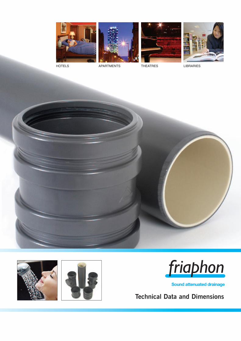
HOTELS APARTMENTS THEATRES LIBRARIES
Technical Data and Dimensions
SOUND ATTENUATED DRAINAGE
Friaphon
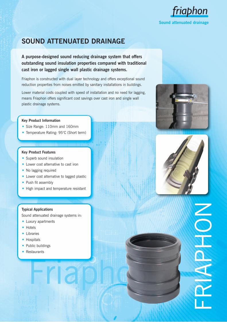
A purpose-designed sound reducing drainage system that offersoutstanding sound insulation properties compared with traditionalcast iron or lagged single wall plastic drainage systems.
Friaphon is constructed with dual layer technology and offers exceptional sound
reduction properties from noises emitted by sanitary installations in buildings.
Lower material costs coupled with speed of installation and no need for lagging,
means Friaphon offers significant cost savings over cast iron and single wall
plastic drainage systems.
Key Product Information
• Size Range: 110mm and 160mm
• Temperature Rating: 95°C (Short term)
Typical Applications
Sound attenuated drainage systems in:
• Luxury apartments
• Hotels
• Libraries
• Hospitals
• Public buildings
• Restaurants
Key Product Features
• Superb sound insulation
• Lower cost alternative to cast iron
• No lagging required
• Lower cost alternative to lagged plastic
• Push fit assembly
• High impact and temperature resistant
FRIAPHON
Sound attenuated drainage

Tel: +44 (0)1543 279909 Fax: +44 (0)1543 2794504
Sound attenuated drainage
System OverviewFriaphon pipe is manufactured by dual
forming two materials of different density.
Friaphon Dual Technology guarantees the
excellent sound insulation and airborne
sound reduction properties of the system.
Sound waves are partially reflected along
the boundary layers to be absorbed by
the pipe’s mass.
Fittings in the Friaphon range achieve a
high sound insulation level due to increased
wall thickness and rubber ring joints.
When using Friaphon double couplers as
standard connectors, pipes can be connected
to each other free of any structure-borne
noises by way of a floating bearing of the
pipe ends. At the same time this enables
expansion to be accommodated.
Installation is by means of rubber lined
support and sliding clips. The support clip
acts as the normal method of anchoring at
individual floor level.
email: [email protected] web: www.durapipe.co.uk 5
Sound attenuated drainage
Contents
System Overview 4-6
Sound Insulation 7
System Description 8-13Properties 8Double coupler 9Fittings 9Fixings 9Product range overview 10-13
Dimensional Data 14-22Pipe 14Double couplers 14Bends 14-15Cushioning sections 15Branches/Boss branches 16-17Access pipes/Boss pipe 17-18Strap-on bosses 18Waste manifold 18Reducers 18-19Sleeves 19Socket plug 19Access cap 19Boss connectors/adaptors 20Unicollar fire protection 20Support clips 21Intermediate sliding clips 21Lubricant 21Primer 21Adhesive 21
Tools 22Pipe cutter 22Chamfering tool 22Reamer 22
Design 23-25
Jointing 26-28
Installation 29-39
Site Work 40
Conformity Certificates 41
Terms and Conditions 42
page
Tel: +44 (0)1543 279909 Fax: +44 (0)1543 2794506
Sound attenuated drainage
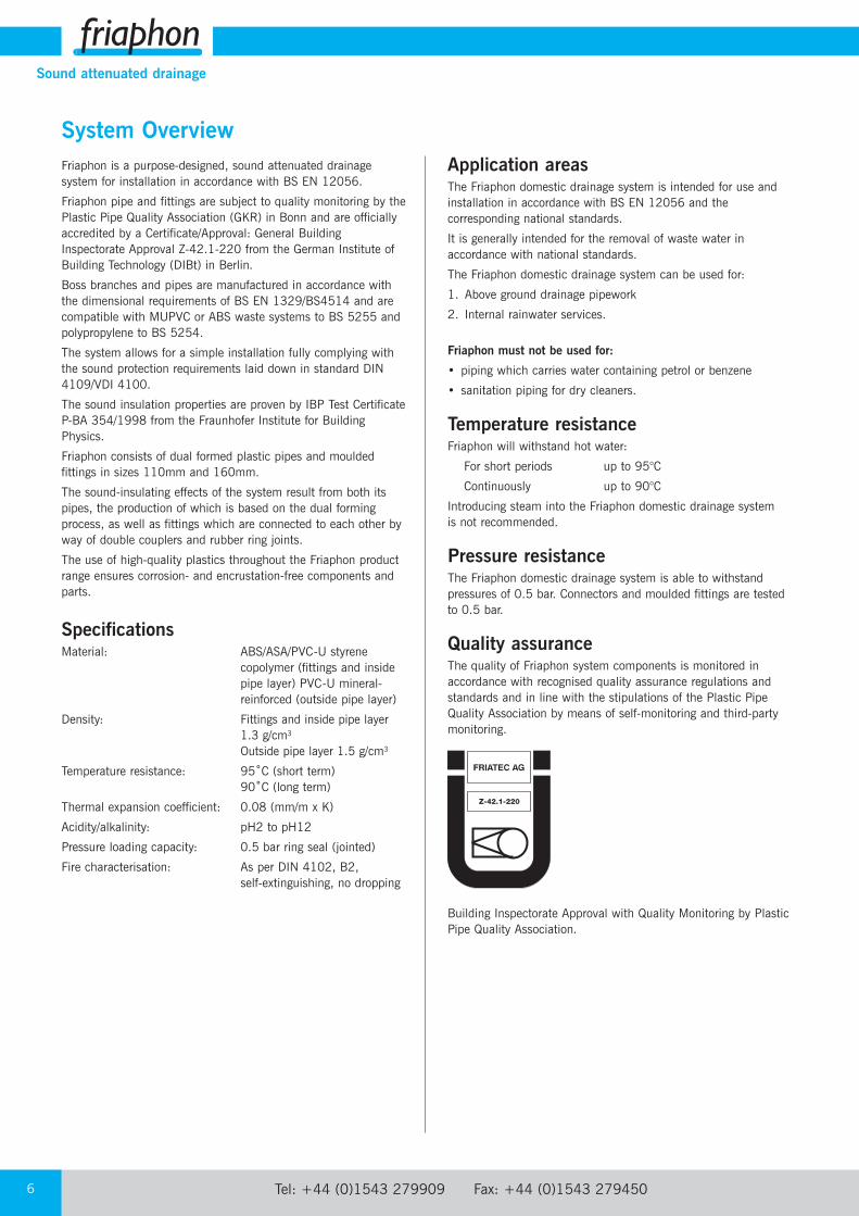
System OverviewFriaphon is a purpose-designed, sound attenuated drainagesystem for installation in accordance with BS EN 12056.
Friaphon pipe and fittings are subject to quality monitoring by thePlastic Pipe Quality Association (GKR) in Bonn and are officiallyaccredited by a Certificate/Approval: General BuildingInspectorate Approval Z-42.1-220 from the German Institute ofBuilding Technology (DIBt) in Berlin.
Boss branches and pipes are manufactured in accordance withthe dimensional requirements of BS EN 1329/BS4514 and arecompatible with MUPVC or ABS waste systems to BS 5255 andpolypropylene to BS 5254.
The system allows for a simple installation fully complying withthe sound protection requirements laid down in standard DIN4109/VDI 4100.
The sound insulation properties are proven by IBP Test CertificateP-BA 354/1998 from the Fraunhofer Institute for BuildingPhysics.
Friaphon consists of dual formed plastic pipes and mouldedfittings in sizes 110mm and 160mm.
The sound-insulating effects of the system result from both itspipes, the production of which is based on the dual formingprocess, as well as fittings which are connected to each other byway of double couplers and rubber ring joints.
The use of high-quality plastics throughout the Friaphon productrange ensures corrosion- and encrustation-free components andparts.
SpecificationsMaterial: ABS/ASA/PVC-U styrene
copolymer (fittings and insidepipe layer) PVC-U mineral-reinforced (outside pipe layer)
Density: Fittings and inside pipe layer1.3 g/cm3
Outside pipe layer 1.5 g/cm3
Temperature resistance: 95˚C (short term)90˚C (long term)
Thermal expansion coefficient: 0.08 (mm/m x K)
Acidity/alkalinity: pH2 to pH12
Pressure loading capacity: 0.5 bar ring seal (jointed)
Fire characterisation: As per DIN 4102, B2,self-extinguishing, no dropping
Application areasThe Friaphon domestic drainage system is intended for use andinstallation in accordance with BS EN 12056 and thecorresponding national standards.
It is generally intended for the removal of waste water inaccordance with national standards.
The Friaphon domestic drainage system can be used for:
1. Above ground drainage pipework
2. Internal rainwater services.
Friaphon must not be used for:
• piping which carries water containing petrol or benzene
• sanitation piping for dry cleaners.
Temperature resistanceFriaphon will withstand hot water:
For short periods up to 95°C
Continuously up to 90°C
Introducing steam into the Friaphon domestic drainage system is not recommended.
Pressure resistanceThe Friaphon domestic drainage system is able to withstandpressures of 0.5 bar. Connectors and moulded fittings are tested to 0.5 bar.
Quality assuranceThe quality of Friaphon system components is monitored inaccordance with recognised quality assurance regulations andstandards and in line with the stipulations of the Plastic PipeQuality Association by means of self-monitoring and third-partymonitoring.
Building Inspectorate Approval with Quality Monitoring by PlasticPipe Quality Association.
Z-42.1-220
email: [email protected] web: www.durapipe.co.uk 7
Sound attenuated drainage
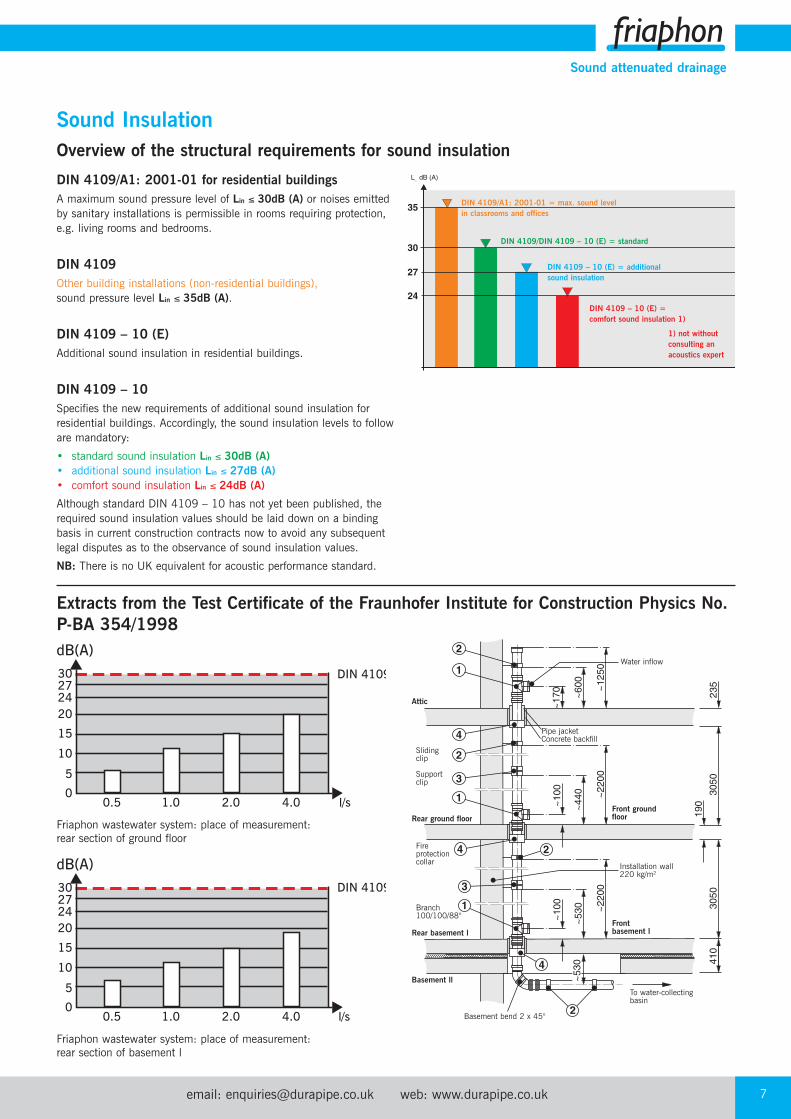
Sound InsulationOverview of the structural requirements for sound insulation
Extracts from the Test Certificate of the Fraunhofer Institute for Construction Physics No.P-BA 354/1998
DIN 4109/A1: 2001-01 for residential buildingsA maximum sound pressure level of Lin ≤ 30dB (A) or noises emittedby sanitary installations is permissible in rooms requiring protection,e.g. living rooms and bedrooms.
DIN 4109Other building installations (non-residential buildings),sound pressure level Lin ≤ 35dB (A).
DIN 4109 – 10 (E)Additional sound insulation in residential buildings.
DIN 4109 – 10Specifies the new requirements of additional sound insulation forresidential buildings. Accordingly, the sound insulation levels to followare mandatory:
• standard sound insulation Lin ≤ 30dB (A)• additional sound insulation Lin ≤ 27dB (A)• comfort sound insulation Lin ≤ 24dB (A)
Although standard DIN 4109 – 10 has not yet been published, therequired sound insulation values should be laid down on a bindingbasis in current construction contracts now to avoid any subsequentlegal disputes as to the observance of sound insulation values.
NB: There is no UK equivalent for acoustic performance standard.
DIN 4109/A1: 2001-01 = max. sound levelin classrooms and offices
DIN 4109/DIN 4109 – 10 (E) = standard
DIN 4109 – 10 (E) = additionalsound insulation
1) not withoutconsulting anacoustics expert
0.5 1.0 2.0 4.0 l/s
DIN 410930272420
15
10
5
0
dB(A)
0.5 1.0 2.0 4.0 l/s
DIN 410930272420
15
10
5
0
dB(A)
Friaphon wastewater system: place of measurement: rear section of ground floor
Friaphon wastewater system: place of measurement: rear section of basement l
Water inflow
Pipe jacketConcrete backfill
Frontbasement l
Installation wall220 kg/m2
Front ground floor
To water-collectingbasin
Basement bend 2 x 45°
Basement ll
Rear basement l
Rear ground floor
Attic
Branch 100/100/88°
Fire protectioncollar
Supportclip
Slidingclip
DIN 4109 – 10 (E) = comfort sound insulation 1)
Tel: +44 (0)1543 279909 Fax: +44 (0)1543 2794508
Sound attenuated drainage
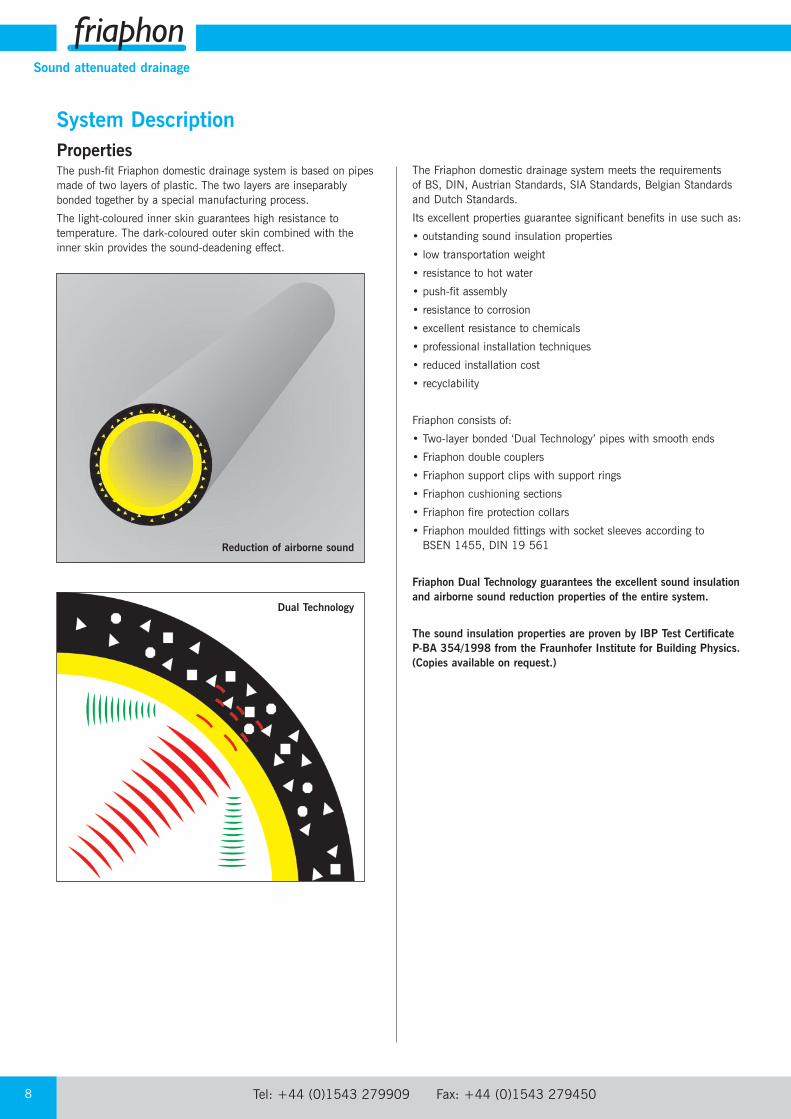
System DescriptionPropertiesThe push-fit Friaphon domestic drainage system is based on pipesmade of two layers of plastic. The two layers are inseparablybonded together by a special manufacturing process.
The light-coloured inner skin guarantees high resistance totemperature. The dark-coloured outer skin combined with theinner skin provides the sound-deadening effect.
The Friaphon domestic drainage system meets the requirements of BS, DIN, Austrian Standards, SIA Standards, Belgian Standardsand Dutch Standards.
Its excellent properties guarantee significant benefits in use such as:
• outstanding sound insulation properties
• low transportation weight
• resistance to hot water
• push-fit assembly
• resistance to corrosion
• excellent resistance to chemicals
• professional installation techniques
• reduced installation cost
• recyclability
Friaphon consists of:
• Two-layer bonded ‘Dual Technology’ pipes with smooth ends
• Friaphon double couplers
• Friaphon support clips with support rings
• Friaphon cushioning sections
• Friaphon fire protection collars
• Friaphon moulded fittings with socket sleeves according to BSEN 1455, DIN 19 561
Friaphon Dual Technology guarantees the excellent sound insulationand airborne sound reduction properties of the entire system.
The sound insulation properties are proven by IBP Test CertificateP-BA 354/1998 from the Fraunhofer Institute for Building Physics.(Copies available on request.)
Reduction of airborne sound
Dual Technology

email: [email protected] web: www.durapipe.co.uk 9
Sound attenuated drainage
System DescriptionFriaphon double couplerThe Friaphon double coupler prevents the transmission of soundalong pipes and compensates for thermal expansion. The Friaphondouble coupler is used for connecting pipe to moulded fittings andpipe to pipe.
The integral compensation for expansion and the ‘floatingmounting’ of the pipe ensure simple installation. The transmissionof structure-borne sound (longitudinal transmission of sound) isprevented.
Friaphon fittingsFittings in the Friaphon range achieve a high sound insulation levelresulting from minor sound vibrations.
Friaphon fixingsInstallation is by means of sound proofing, rubber lined support and sliding clips. The support clip acts as the normal method ofanchoring at individual floor levels.
Support ring
Support clip
Wall attachment
Mounting with bolt screw Sliding clip
Sectional representation of Friaphon double coupler.
Tel: +44 (0)1543 279909 Fax: +44 (0)1543 27945010
Sound attenuated drainage
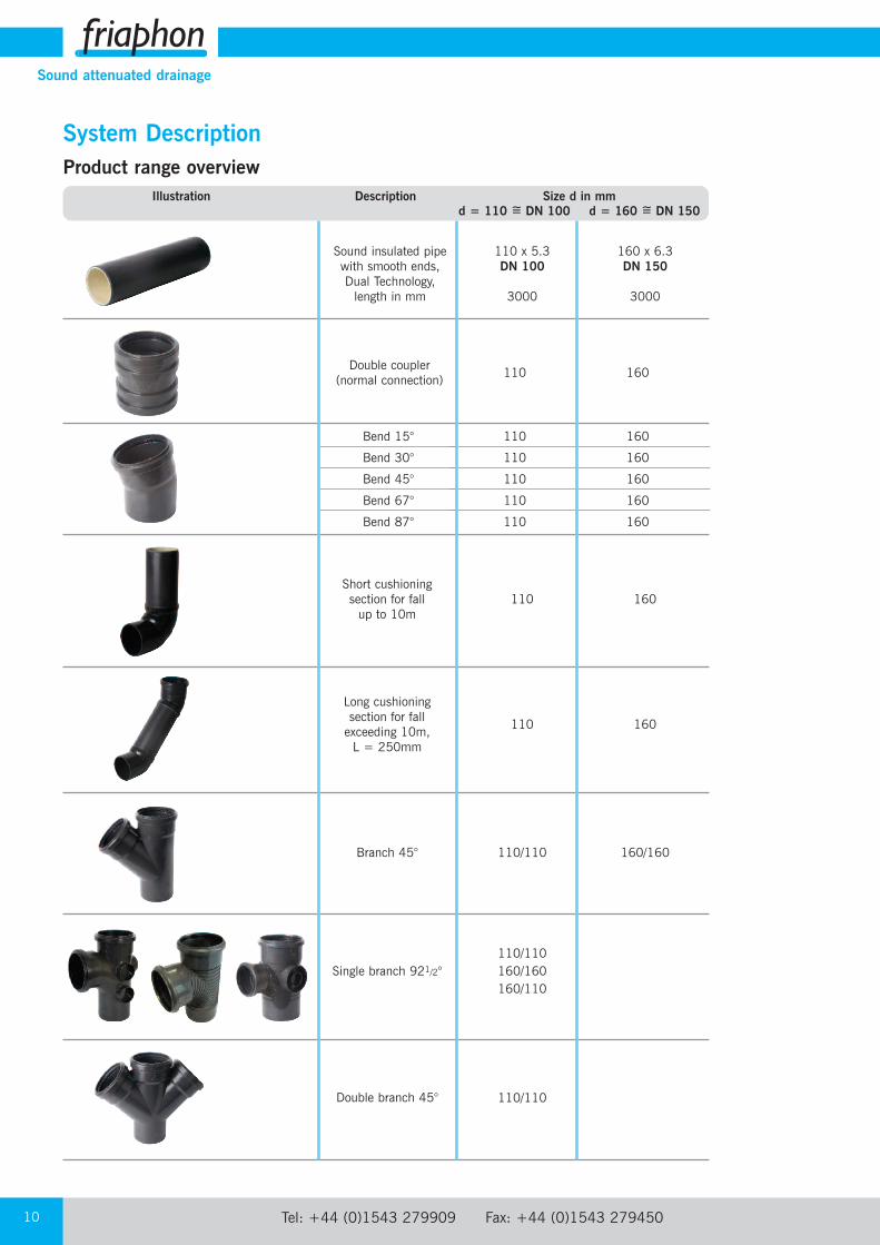
System DescriptionProduct range overview
Illustration Description Size d in mmd = 110 =~ DN 100 d = 160 =~ DN 150
Sound insulated pipewith smooth ends,Dual Technology,length in mm
110 x 5.3 160 x 6.3DN 100 DN 150
3000 3000
Double coupler (normal connection)
110 160
Short cushioning section for fall up to 10m
110 160
Long cushioning section for fall exceeding 10m, L = 250mm
110 160
Bend 15°
Bend 30°
Bend 45°
Bend 67°
Bend 87°
110 160
110 160
110 160
110 160
110 160
Double branch 45° 110/110
Branch 45° 110/110 160/160
Single branch 921/2°110/110160/160160/110

email: [email protected] web: www.durapipe.co.uk 11
Sound attenuated drainage
Illustration Description Size d in mmd = 110 =~ DN 100 d = 160 =~ DN 150
Double branch 921/2° 110/110
Corner branch 921/2° 110/110
Boss pipe 110 160
System DescriptionProduct range overview
Access pipes 110 160
Access boss pipe 110
Strap-on boss
110/32110/40110/50160/50
Waste manifold 110
Reducers 160/110 110/50

Tel: +44 (0)1543 279909 Fax: +44 (0)1543 27945012
Sound attenuated drainage
Illustration Description Size d in mmd = 110 =~ DN 100 d = 160 =~ DN 150
Unicollar fire protection
2250mm strip length
Screwed access cap 110
Boss adaptor (Rubber)
32, 40
Boss connector 32, 40, 50
System DescriptionProduct range overview
Boss adaptor(Waste Manifold)
50
Boss adaptor (Solvent Weld)
50
Bonding sleeve/Double bonding sleeve
110 160
Sleeve(for repair purposes)
110 160
Socket plug 110

email: [email protected] web: www.durapipe.co.uk 13
Sound attenuated drainage
Illustration Description Size d in mmd = 110 =~ DN 100 d = 160 =~ DN 150
Adhesive 500 ml
Primer 500 ml
Pipe cutter 50/125
Chamfering tool
Reamer
System DescriptionProduct range overview
Lubricant 125 gram
Support clip with support ring and wall fixing
110 160
Intermediate sliding clip
110 160
Tel: +44 (0)1543 279909 Fax: +44 (0)1543 27945014
Sound attenuated drainage
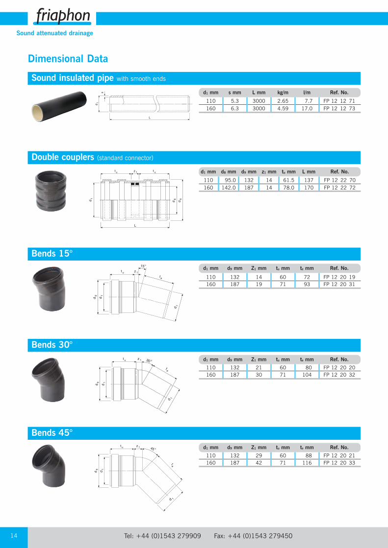
Double couplers (standard connector)d1 mm d8 mm d9 mm z1 mm tu mm L mm Ref. No.
110 95.0 132 14 61.5 137 FP 12 22 70160 142.0 187 14 78.0 170 FP 12 22 72
Bends 15°d1 mm d9 mm Z1 mm tu mm te mm Ref. No.
110 132 14 60 72 FP 12 20 19160 187 19 71 93 FP 12 20 31
Bends 30°d1 mm d9 mm Z1 mm tu mm te mm Ref. No.
110 132 21 60 80 FP 12 20 20160 187 30 71 104 FP 12 20 32
Bends 45°d1 mm d9 mm Z1 mm tu mm te mm Ref. No.
110 132 29 60 88 FP 12 20 21160 187 42 71 116 FP 12 20 33
Dimensional Data
Sound insulated pipe with smooth endsd1 mm s mm L mm kg/m l/m Ref. No.
110 5.3 3000 2.65 7.7 FP 12 12 71160 6.3 3000 4.59 17.0 FP 12 12 73
email: [email protected] web: www.durapipe.co.uk 15
Sound attenuated drainage
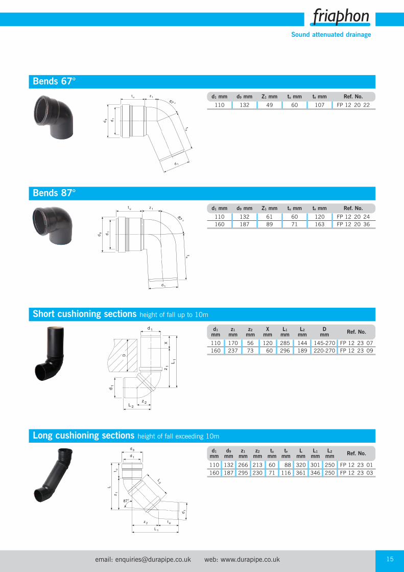
Bends 67°d1 mm d9 mm Z1 mm tu mm te mm Ref. No.
110 132 49 60 107 FP 12 20 22
Bends 87°d1 mm d9 mm Z1 mm tu mm te mm Ref. No.
110 132 61 60 120 FP 12 20 24160 187 89 71 163 FP 12 20 36
Short cushioning sections height of fall up to 10md1 z1 z2 X L1 L2 D Ref. No.mm mm mm mm mm mm mm
110 170 56 120 285 144 145-270 FP 12 23 07160 237 73 60 296 189 220-270 FP 12 23 09
Long cushioning sections height of fall exceeding 10md1 d9 z1 z2 tu te L L1 L2 Ref. No.mm mm mm mm mm mm mm mm mm
110 132 266 213 60 88 320 301 250 FP 12 23 01160 187 295 230 71 116 361 346 250 FP 12 23 03
Tel: +44 (0)1543 279909 Fax: +44 (0)1543 27945016
Sound attenuated drainage
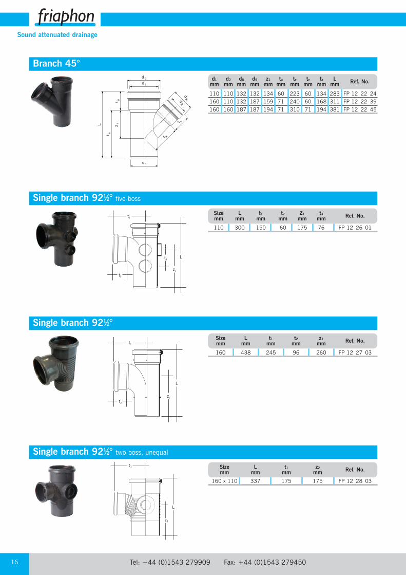
Branch 45°d1 d2 d8 d9 z1 tu te tv tx L Ref. No.mm mm mm mm mm mm mm mm mm mm
110 110 132 132 134 60 223 60 134 283 FP 12 22 24160 110 132 187 159 71 240 60 168 311 FP 12 22 39160 160 187 187 194 71 310 71 194 381 FP 12 22 45
L
t2
t1
z1
Single branch 921⁄2°
L
t2
t1
z1
t3
Single branch 921⁄2° five boss Size L t1 t2 Z1 t3 Ref. No.mm mm mm mm mm mm
110 300 150 60 175 76 FP 12 26 01
Single branch 921⁄2° two boss, unequal
L
t1
z1
Size L t1 t2 z1 Ref. No.mm mm mm mm mm
160 438 245 96 260 FP 12 27 03
Size L t1 z2 Ref. No.mm mm mm mm
160 x 110 337 175 175 FP 12 28 03
email: [email protected] web: www.durapipe.co.uk 17
Sound attenuated drainage
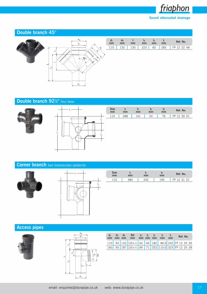
Double branch 921⁄2° four boss Size L t1 t2 t3 Ref. No.mm mm mm mm mm
110 288 141 54 76 FP 12 30 01
L
t2
t1
t3
Access pipesd1 d4 d9 Rd z1 tu te tx L Ref. No.mm mm mm mm mm mm mm mm mm
110 93 132 110 x 1⁄6 62 60 182 80.0 242 FP 12 25 26
160 93 187 110 x 1⁄6 89 71 252 110.0 323 FP 12 25 28
Double branch 45°d1 d9 t te tu L Ref. No.mm mm mm mm mm mm
110 132 130 223 60 283 FP 12 22 48
t1
L
t2
Corner branch two boss/access upstandsSize L t1 t2 Ref. No.mm mm mm mm
110 384 242 190 FP 12 31 01
Tel: +44 (0)1543 279909 Fax: +44 (0)1543 27945018
Sound attenuated drainage
L
t2
z1
t5 t4
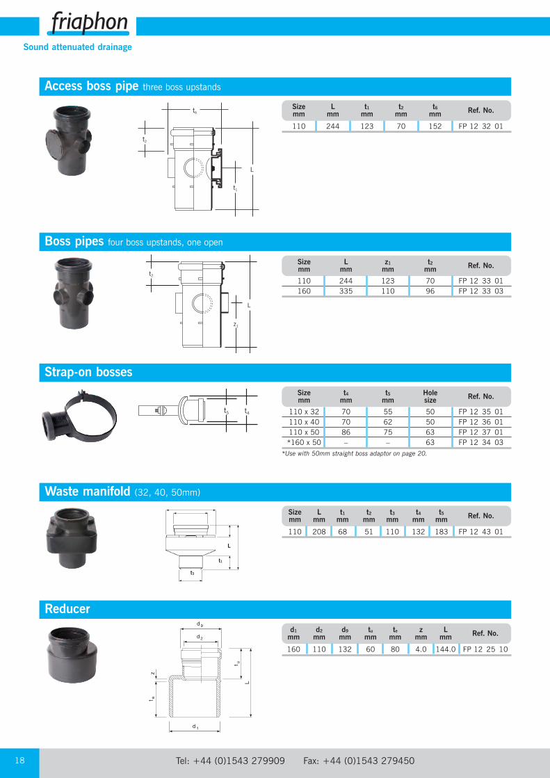
Boss pipes four boss upstands, one openSize L z1 t2 Ref. No.mm mm mm mm
110 244 123 70 FP 12 33 01160 335 110 96 FP 12 33 03
Strap-on bosses
Waste manifold (32, 40, 50mm)Size L t1 t2 t3 t4 t5 Ref. No.mm mm mm mm mm mm mm
110 208 68 51 110 132 183 FP 12 43 01
Reducerd1 d2 d9 tu te z L Ref. No.mm mm mm mm mm mm mm
160 110 132 60 80 4.0 144.0 FP 12 25 10
Access boss pipe three boss upstandsSize L t1 t2 t6 Ref. No.mm mm mm mm mm
110 244 123 70 152 FP 12 32 01
L
t2
t1
t6
Size t4 t5 Hole Ref. No.mm mm mm size
110 x 32 70 55 50 FP 12 35 01110 x 40 70 62 50 FP 12 36 01110 x 50 86 75 63 FP 12 37 01*160 x 50 – – 63 FP 12 34 03
*Use with 50mm straight boss adaptor on page 20.
L
t1
t3

email: [email protected] web: www.durapipe.co.uk 19
Sound attenuated drainage
Sleevesd1 d9 t L Ref. No.mm mm mm mm
110 132 62.5 125 FP 12 25 30160 187 79.0 158 FP 12 25 32
Bonding sleevesd1 d9 tu t L Ref. No.mm mm mm mm mm
110 132 60 32 95 FP 12 25 44160 187 71 42 117 FP 12 25 46
Socket plugd1 d9 t s L Ref. No.mm mm mm mm mm
110 120 32.0 5 41.5 FP 12 25 40
t2
t6
Access cap solvent socket, screwed
Reducer solvent socket, single boss upstandSize L t9 t2 Ref. No.mm mm mm mm
110 x 50 48 25 19 FP 12 38 01
Size t6 t2 Ref. No.mm mm mm
110 140 30 FP 12 42 01
Double bonding sleevesd1 d9 t L Ref. No.mm mm mm mm
110 115 35 73 FP 12 25 62160 167 42 88 FP 12 25 64
t2
Lt9
Tel: +44 (0)1543 279909 Fax: +44 (0)1543 27945020
Sound attenuated drainage
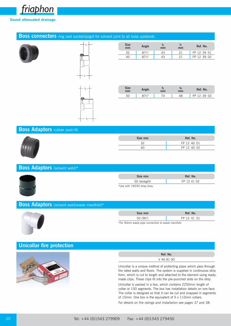
Boss connectors ring seal socket/spigot for solvent joint to all boss upstands
t2
t7
t2
t8
Unicollar fire protection
Unicollar is a unique method of protecting pipes which pass throughfire rated walls and floors. The system is supplied in continuous stripform, which is cut to length and attached to the element using ready-made clips. These clips fit into the pre-punched slots on the strip.
Unicollar is packed in a box, which contains 2250mm length ofcollar or 150 segments. The box has installation details on one face.The collar is designed so that it can be cut and snapped in segmentsof 15mm. One box is the equivalent of 5 x 110mm collars.
For details on fire ratings and installation see pages 37 and 38.
Boss Adaptors rubber push-fitSize mm Ref. No.
32 FP 12 40 0140 FP 12 40 02
Boss Adaptors (solvent weld/waste manifold)*Size mm Ref. No.
50 (90°) FP 12 41 01*For 50mm waste pipe connection to waste manifold.
Ref. No.
V 46 81 00
Size Angle t2 t7 Ref. No.mm mm mm
32 871⁄2° 43 21 FP 12 39 0140 871⁄2° 43 21 FP 12 39 02
Size Angle t2 t8 Ref. No.mm mm mm
50 871⁄2° 74 48 FP 12 39 03
Boss Adaptors (solvent weld)*Size mm Ref. No.
50 (straight) FP 12 41 02 *Use with 160/50 strap boss.

email: [email protected] web: www.durapipe.co.uk 21
Sound attenuated drainage
Support clips with support ring and wall fixingd mm Ref. No.
110 FP 12 13 01160 FP 12 13 03
AdhesiveContents ml Ref. No.
500 FP 12 29 80
PrimerContents ml Ref. No.
500 FP 12 29 90
LubricantContents g Ref. No.
125 FP 12 29 70
Intermediate sliding clipsd mm Ref. No.
110 FTPC 1100160 FTPC 1601
Tel: +44 (0)1543 279909 Fax: +44 (0)1543 27945022
Sound attenuated drainage
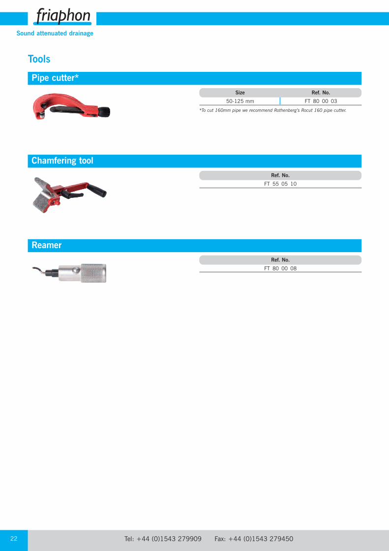
Chamfering toolRef. No.
FT 55 05 10
ReamerRef. No.
FT 80 00 08
Size Ref. No.
50-125 mm FT 80 00 03
*To cut 160mm pipe we recommend Rothenberg’s Rocut 160 pipe cutter.
Pipe cutter*
Tools
email: [email protected] web: www.durapipe.co.uk 23
Sound attenuated drainage
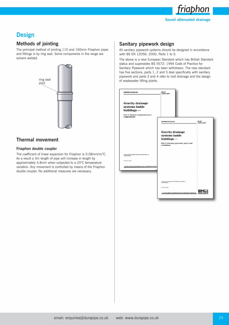
DesignMethods of jointingThe principal method of jointing 110 and 160mm Friaphon pipesand fittings is by ring seal. Some components in the range aresolvent welded.
Thermal movement
Friaphon double couplerThe coefficient of linear expansion for Friaphon is 0.08mm/m/°C.As a result a 3m length of pipe will increase in length byapproximately 4.8mm when subjected to a 20°C temperaturevariation. Any movement is controlled by means of the Friaphondouble coupler. No additional measures are necessary.
ring sealjoint
Sanitary pipework designAll sanitary pipework systems should be designed in accordancewith BS EN 12056: 2000, Parts 1 to 5.
The above is a new European Standard which has British Standardstatus and supersedes BS 5572: 1994 Code of Practice forSanitary Pipework which has been withdrawn. The new standardhas five sections, parts 1, 2 and 5 deal specifically with sanitarypipework and parts 3 and 4 refer to roof drainage and the design of wastewater lifting plants.
Tel: +44 (0)1543 279909 Fax: +44 (0)1543 27945024
Sound attenuated drainage
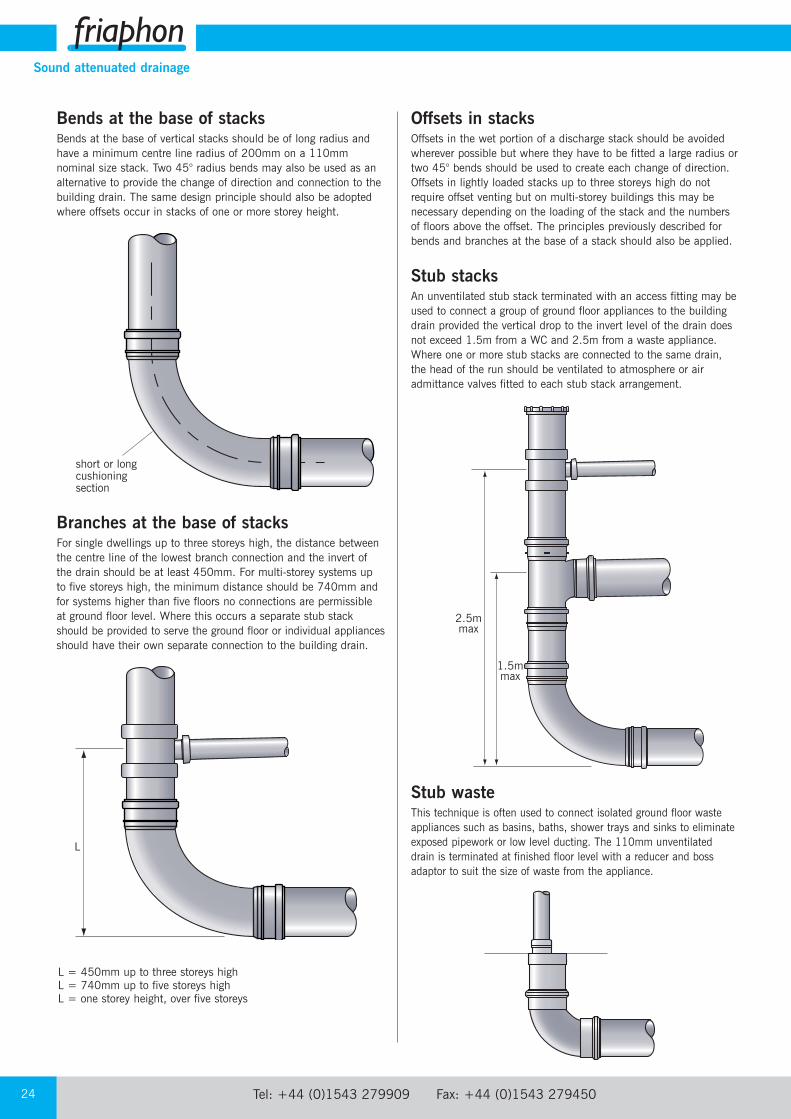
Bends at the base of stacksBends at the base of vertical stacks should be of long radius andhave a minimum centre line radius of 200mm on a 110mmnominal size stack. Two 45° radius bends may also be used as analternative to provide the change of direction and connection to thebuilding drain. The same design principle should also be adoptedwhere offsets occur in stacks of one or more storey height.
Branches at the base of stacksFor single dwellings up to three storeys high, the distance betweenthe centre line of the lowest branch connection and the invert of the drain should be at least 450mm. For multi-storey systems up to five storeys high, the minimum distance should be 740mm andfor systems higher than five floors no connections are permissible at ground floor level. Where this occurs a separate stub stackshould be provided to serve the ground floor or individual appliancesshould have their own separate connection to the building drain.
L = 450mm up to three storeys highL = 740mm up to five storeys highL = one storey height, over five storeys
L
short or longcushioningsection
Offsets in stacksOffsets in the wet portion of a discharge stack should be avoidedwherever possible but where they have to be fitted a large radius ortwo 45° bends should be used to create each change of direction.Offsets in lightly loaded stacks up to three storeys high do notrequire offset venting but on multi-storey buildings this may benecessary depending on the loading of the stack and the numbersof floors above the offset. The principles previously described forbends and branches at the base of a stack should also be applied.
Stub stacksAn unventilated stub stack terminated with an access fitting may beused to connect a group of ground floor appliances to the buildingdrain provided the vertical drop to the invert level of the drain doesnot exceed 1.5m from a WC and 2.5m from a waste appliance.Where one or more stub stacks are connected to the same drain,the head of the run should be ventilated to atmosphere or airadmittance valves fitted to each stub stack arrangement.
Stub wasteThis technique is often used to connect isolated ground floor wasteappliances such as basins, baths, shower trays and sinks to eliminateexposed pipework or low level ducting. The 110mm unventilateddrain is terminated at finished floor level with a reducer and bossadaptor to suit the size of waste from the appliance.
1.5mmax
2.5mmax

email: [email protected] web: www.durapipe.co.uk 25
Sound attenuated drainage
Prevention of cross-flowWhere small diameter branch waste pipes connect to a dischargestack they must be arranged to eliminate the risk of cross-flowfrom one branch to the other. A branch creates a no entry zone foropposing waste connections, which varies depending on the stackdiameter. No connections should be made within the restrictedzone although entry is permissible on the centre line of theboundary directly opposite or at right angles.
H
H
To prevent cross-flow from a large diameter branch to a smallerwaste connection, the latter should be made to the stack at orabove the centre line of the larger branch, at right angles or atleast 200mm below the restricted zone. Entry is permissible onthe boundary centre line directly opposite or at right angles.
‘H’ = 200mm irrespective of stack diameter
Stack Height of zonesize ‘H’
110mm 110mm160mm 250mm
Tel: +44 (0)1543 279909 Fax: +44 (0)1543 27945026
Sound attenuated drainage
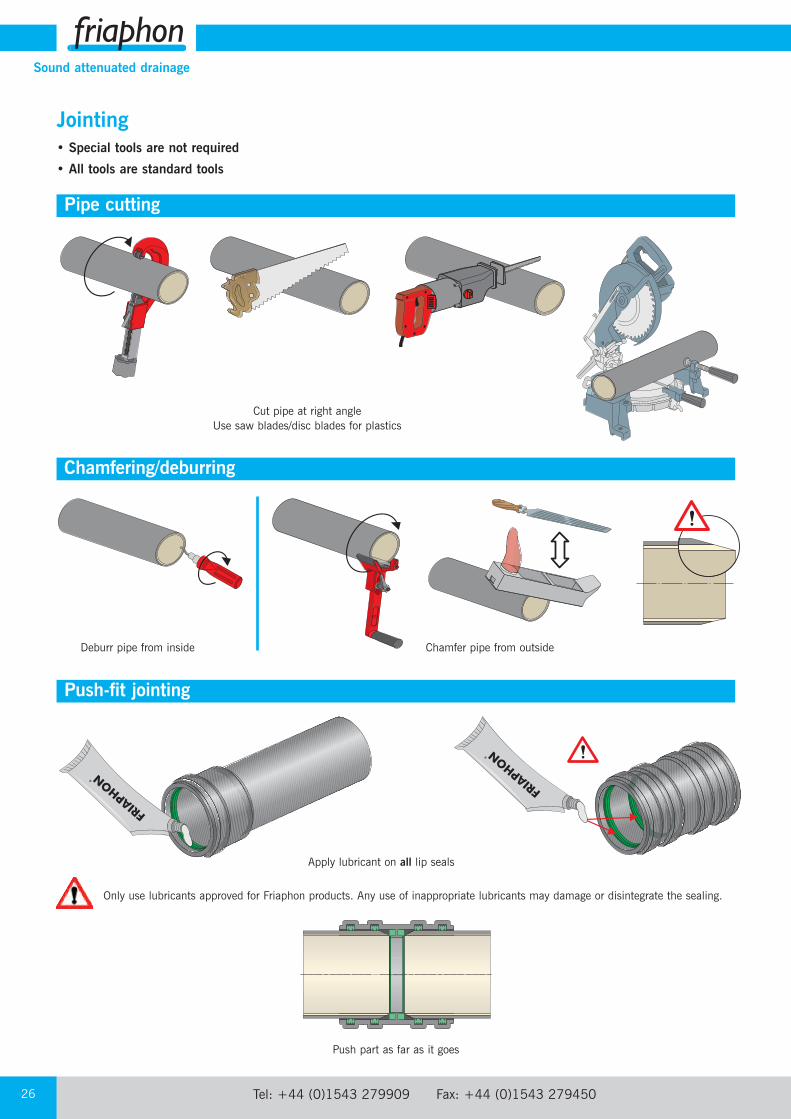
Jointing• Special tools are not required
• All tools are standard tools
Pipe cutting
Chamfering/deburring
Push-fit jointing
Deburr pipe from inside Chamfer pipe from outside
Cut pipe at right angleUse saw blades/disc blades for plastics
Apply lubricant on all lip seals
Push part as far as it goes
Only use lubricants approved for Friaphon products. Any use of inappropriate lubricants may damage or disintegrate the sealing.
email: [email protected] web: www.durapipe.co.uk 27
Sound attenuated drainage
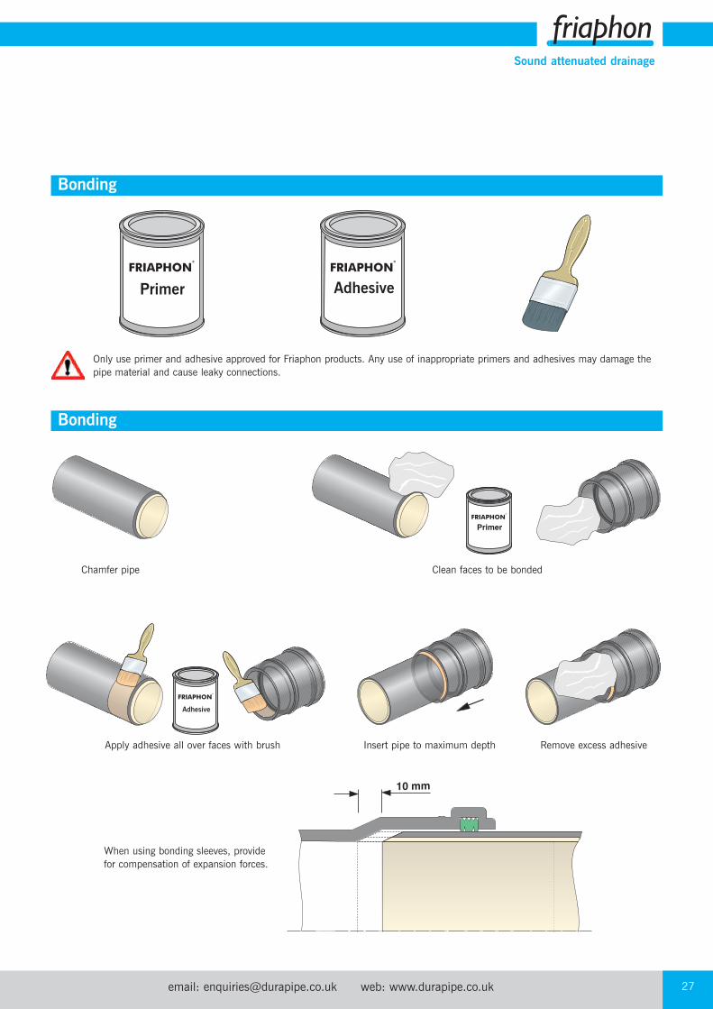
Bonding
Apply adhesive all over faces with brush
When using bonding sleeves, provide for compensation of expansion forces.
Insert pipe to maximum depth Remove excess adhesive
Clean faces to be bondedChamfer pipe
Bonding
Only use primer and adhesive approved for Friaphon products. Any use of inappropriate primers and adhesives may damage thepipe material and cause leaky connections.
AdhesivePrimer
Adhesive
Tel: +44 (0)1543 279909 Fax: +44 (0)1543 27945028
Sound attenuated drainage
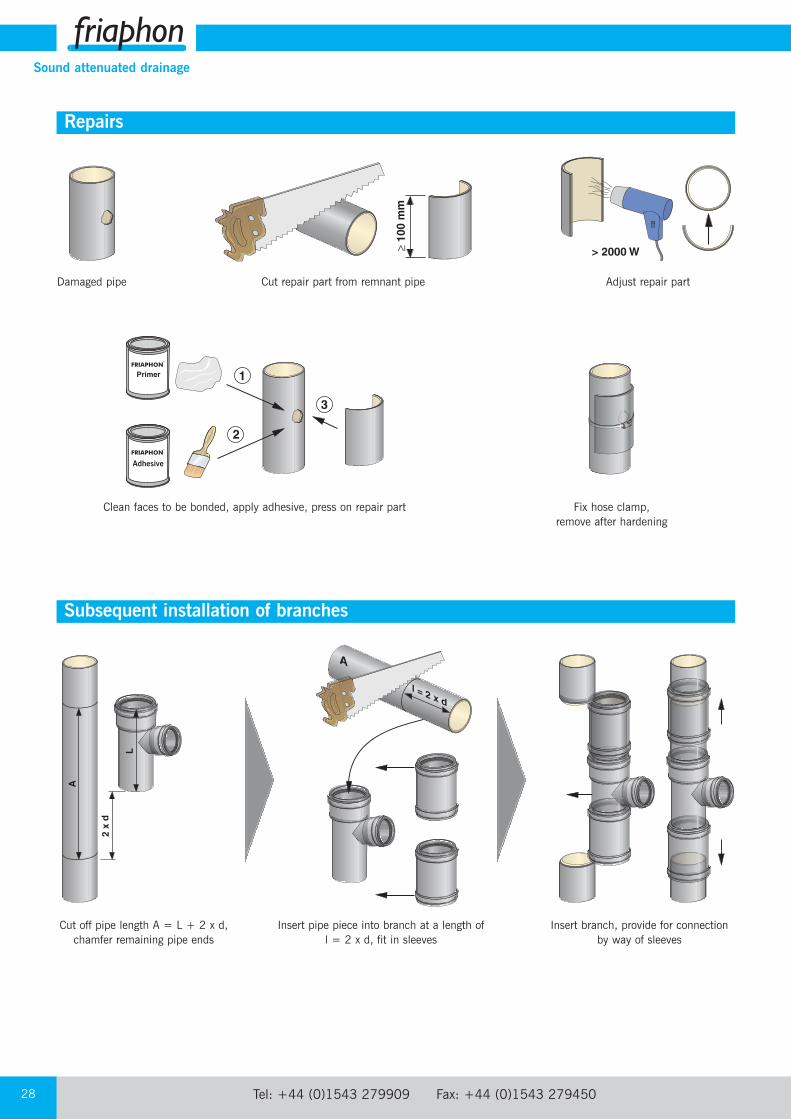
Repairs
Subsequent installation of branches
Damaged pipe Cut repair part from remnant pipe Adjust repair part
Clean faces to be bonded, apply adhesive, press on repair part Fix hose clamp, remove after hardening
Cut off pipe length A = L + 2 x d,chamfer remaining pipe ends
Insert pipe piece into branch at a length of l = 2 x d, fit in sleeves
Insert branch, provide for connection by way of sleeves
Adhesive
email: [email protected] web: www.durapipe.co.uk 29
Sound attenuated drainage
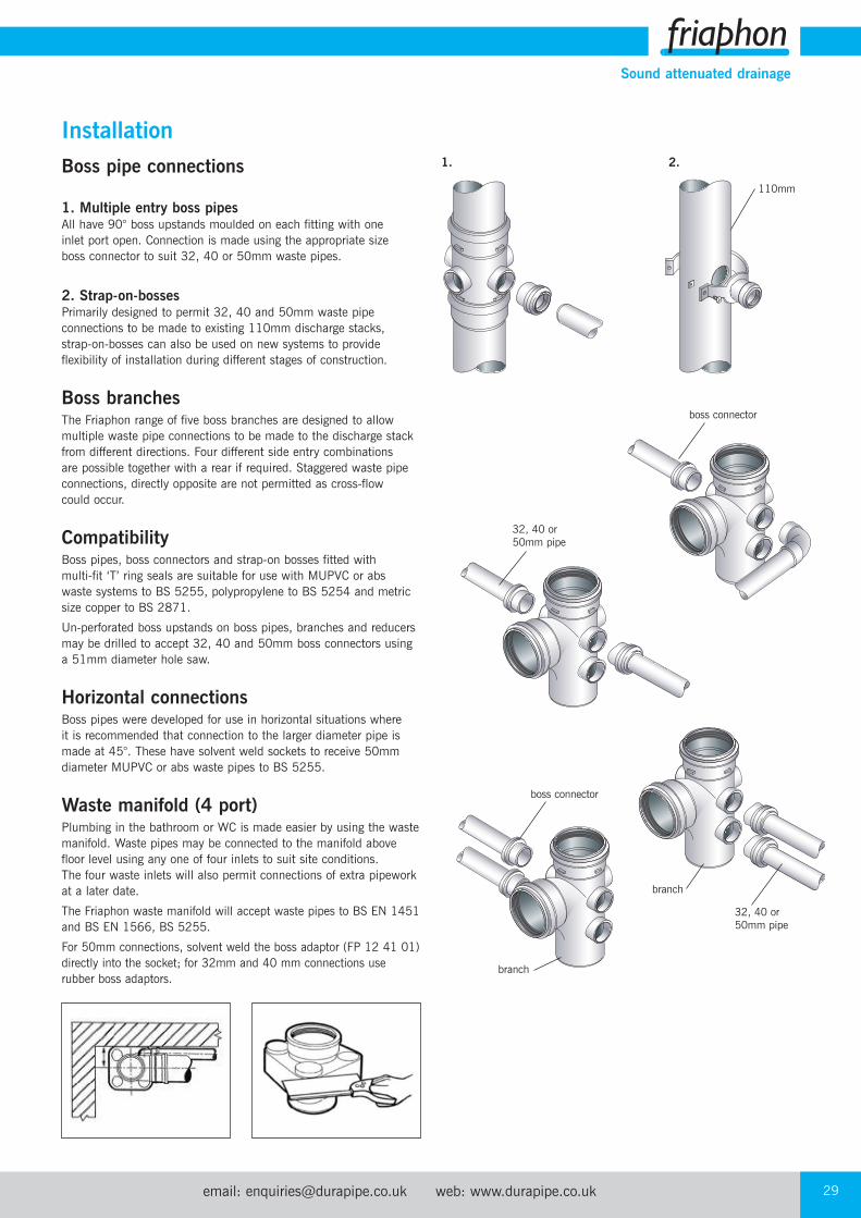
Boss pipe connections
1. Multiple entry boss pipesAll have 90° boss upstands moulded on each fitting with one inlet port open. Connection is made using the appropriate size boss connector to suit 32, 40 or 50mm waste pipes.
2. Strap-on-bossesPrimarily designed to permit 32, 40 and 50mm waste pipeconnections to be made to existing 110mm discharge stacks, strap-on-bosses can also be used on new systems to provideflexibility of installation during different stages of construction.
Boss branchesThe Friaphon range of five boss branches are designed to allowmultiple waste pipe connections to be made to the discharge stackfrom different directions. Four different side entry combinations are possible together with a rear if required. Staggered waste pipeconnections, directly opposite are not permitted as cross-flow could occur.
CompatibilityBoss pipes, boss connectors and strap-on bosses fitted with multi-fit ‘T’ ring seals are suitable for use with MUPVC or abs waste systems to BS 5255, polypropylene to BS 5254 and metricsize copper to BS 2871.
Un-perforated boss upstands on boss pipes, branches and reducersmay be drilled to accept 32, 40 and 50mm boss connectors usinga 51mm diameter hole saw.
Horizontal connectionsBoss pipes were developed for use in horizontal situations where it is recommended that connection to the larger diameter pipe ismade at 45°. These have solvent weld sockets to receive 50mmdiameter MUPVC or abs waste pipes to BS 5255.
Waste manifold (4 port)Plumbing in the bathroom or WC is made easier by using the wastemanifold. Waste pipes may be connected to the manifold abovefloor level using any one of four inlets to suit site conditions. The four waste inlets will also permit connections of extra pipeworkat a later date.
The Friaphon waste manifold will accept waste pipes to BS EN 1451and BS EN 1566, BS 5255.
For 50mm connections, solvent weld the boss adaptor (FP 12 41 01)directly into the socket; for 32mm and 40 mm connections userubber boss adaptors.
Installation
110mm
boss connector
32, 40 or 50mm pipe
32, 40 or 50mm pipe
branch
branch
boss connector
1. 2.
Tel: +44 (0)1543 279909 Fax: +44 (0)1543 27945030
Sound attenuated drainage
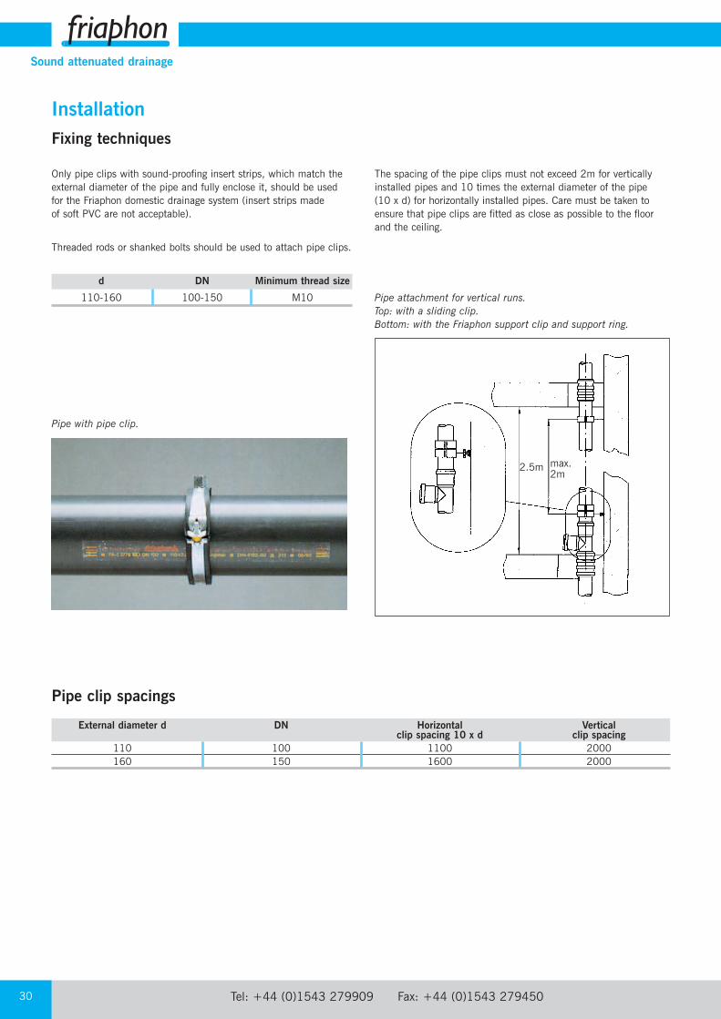
Fixing techniques
Only pipe clips with sound-proofing insert strips, which match theexternal diameter of the pipe and fully enclose it, should be usedfor the Friaphon domestic drainage system (insert strips made of soft PVC are not acceptable).
Threaded rods or shanked bolts should be used to attach pipe clips.
d DN Minimum thread size
110-160 100-150 M10
The spacing of the pipe clips must not exceed 2m for verticallyinstalled pipes and 10 times the external diameter of the pipe (10 x d) for horizontally installed pipes. Care must be taken toensure that pipe clips are fitted as close as possible to the floor and the ceiling.
Pipe with pipe clip.
Pipe attachment for vertical runs.Top: with a sliding clip.Bottom: with the Friaphon support clip and support ring.
External diameter d DN Horizontal Verticalclip spacing 10 x d clip spacing
110 100 1100 2000160 150 1600 2000
Pipe clip spacings
2.5m max.2m
Installation
email: [email protected] web: www.durapipe.co.uk 31
Sound attenuated drainage
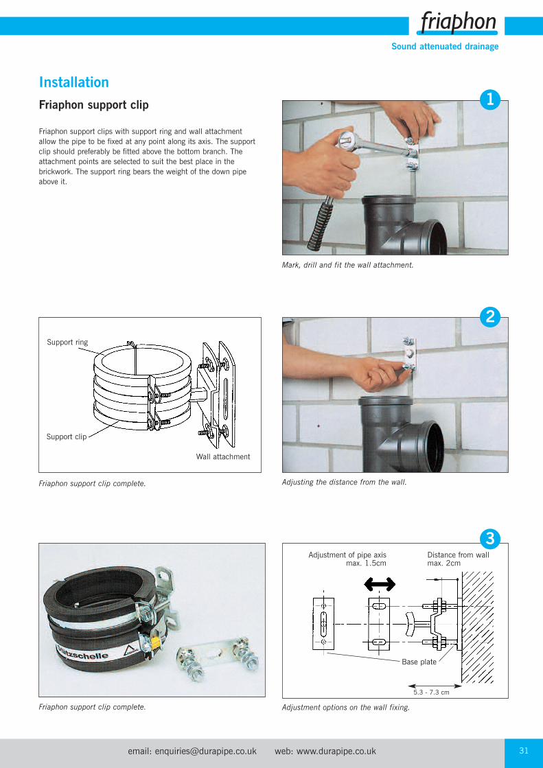
Friaphon support clip
Friaphon support clips with support ring and wall attachmentallow the pipe to be fixed at any point along its axis. The supportclip should preferably be fitted above the bottom branch. Theattachment points are selected to suit the best place in thebrickwork. The support ring bears the weight of the down pipeabove it.
Friaphon support clip complete.
Friaphon support clip complete.
Mark, drill and fit the wall attachment.
Adjusting the distance from the wall.
Adjustment options on the wall fixing.
Base plate
Support ring
Support clip
Wall attachment
Installation
5.3 - 7.3 cm
1
2
Adjustment of pipe axismax. 1.5cm
Distance from wallmax. 2cm
3
Tel: +44 (0)1543 279909 Fax: +44 (0)1543 27945032
Sound attenuated drainage
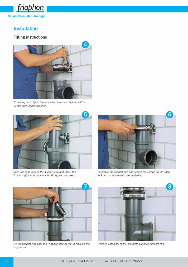
Fitting instructions
Installation
Open the snap lock of the support clip and insert the Friaphon pipe into the moulded fitting and clip fixer.
Fix the support ring onto the Friaphon pipe so that it rests on thesupport clip.
Fit the support clip to the wall attachment and tighten with a17mm open ended spanner.
Assemble the support clip and secure the screws on the snaplock. A spacer prevents overtightening.
Finished assembly of the complete Friaphon support clip.
5 6
7 8
4
email: [email protected] web: www.durapipe.co.uk 33
Sound attenuated drainage
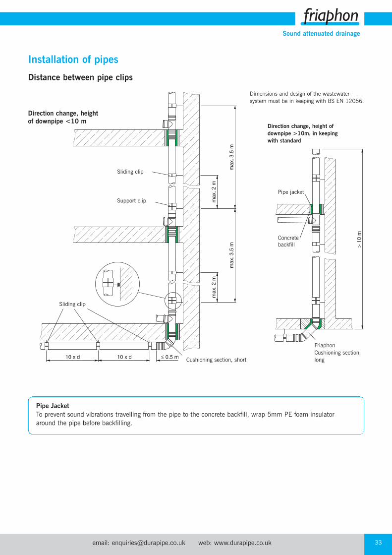
Sliding clip
Pipe jacket
Concretebackfill
Support clip
Direction change, height ofdownpipe >10m, in keepingwith standard
Friaphon Cushioning section,long
Direction change, heightof downpipe <10 m
Cushioning section, short
Dimensions and design of the wastewatersystem must be in keeping with BS EN 12056.
Sliding clip
Distance between pipe clips
Installation of pipes
Pipe JacketTo prevent sound vibrations travelling from the pipe to the concrete backfill, wrap 5mm PE foam insulatoraround the pipe before backfilling.
Tel: +44 (0)1543 279909 Fax: +44 (0)1543 27945034
Sound attenuated drainage
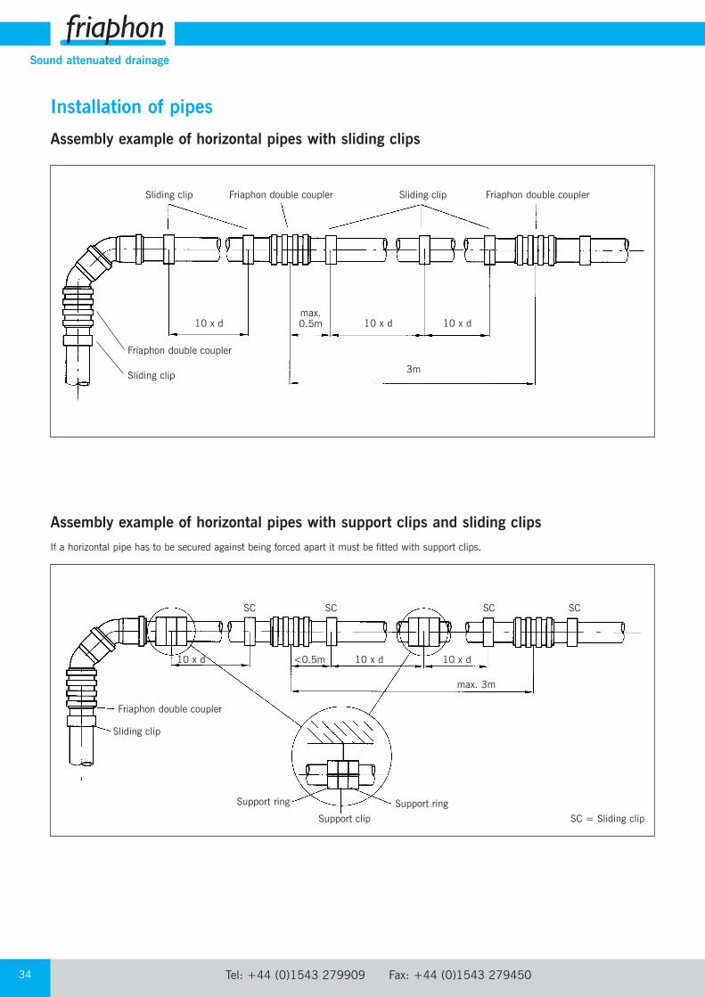
Assembly example of horizontal pipes with sliding clips
Installation of pipes
Assembly example of horizontal pipes with support clips and sliding clipsIf a horizontal pipe has to be secured against being forced apart it must be fitted with support clips.
Sliding clip Friaphon double coupler Sliding clip Friaphon double coupler
10 x dmax.0.5m 10 x d 10 x d
Friaphon double coupler
Sliding clip3m
SC SC SC SC
10 x d <0.5m 10 x d 10 x d
Friaphon double coupler
Sliding clip
max. 3m
Support ring
Support clipSupport ring
SC = Sliding clip
email: [email protected] web: www.durapipe.co.uk 35
Sound attenuated drainage
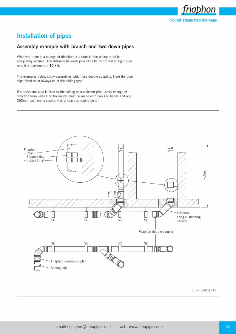
Wherever there is a change of direction or a branch, the piping must beadequately secured. The distance between pipe clips for horizontal straight piperuns is a maximum of 10 x d.
The examples below show assemblies which use double couplers. Here the pipeclips fitted must always be of the sliding type.
If a horizontal pipe is fixed to the ceiling as a collector pipe, every change ofdirection from vertical to horizontal must be made with two 45° bends and one250mm cushioning section (i.e. a long cushioning bend).
Installation of pipes
Friaphon-– Pipe– Support ring– Support clip
SC SC SC SC
SC SC SC SC
Friaphon double coupler
Sliding clip
Friaphon double coupler
FriaphonLong cushioningsection
SC = Sliding clip
>10m
Assembly example with branch and two down pipes

Tel: +44 (0)1543 279909 Fax: +44 (0)1543 27945036
Sound attenuated drainage
Assembling short runs of pipes
Even when assembling short horizontal runs of pipe with a length ≤ 10x d, as shown in the illustration, a sliding clip must be fitted as close aspossible to the cushioning section in order to stabilise the position.
Installation of pipes
Friaphon-– Pipe– Support ring– Support clip
SC≤ 10 x d ≤ 0.5m
SC
FriaphonShort cushioningsection
≤10mm
Concrete backfill
Pipe jacket
email: [email protected] web: www.durapipe.co.uk 37
Sound attenuated drainage
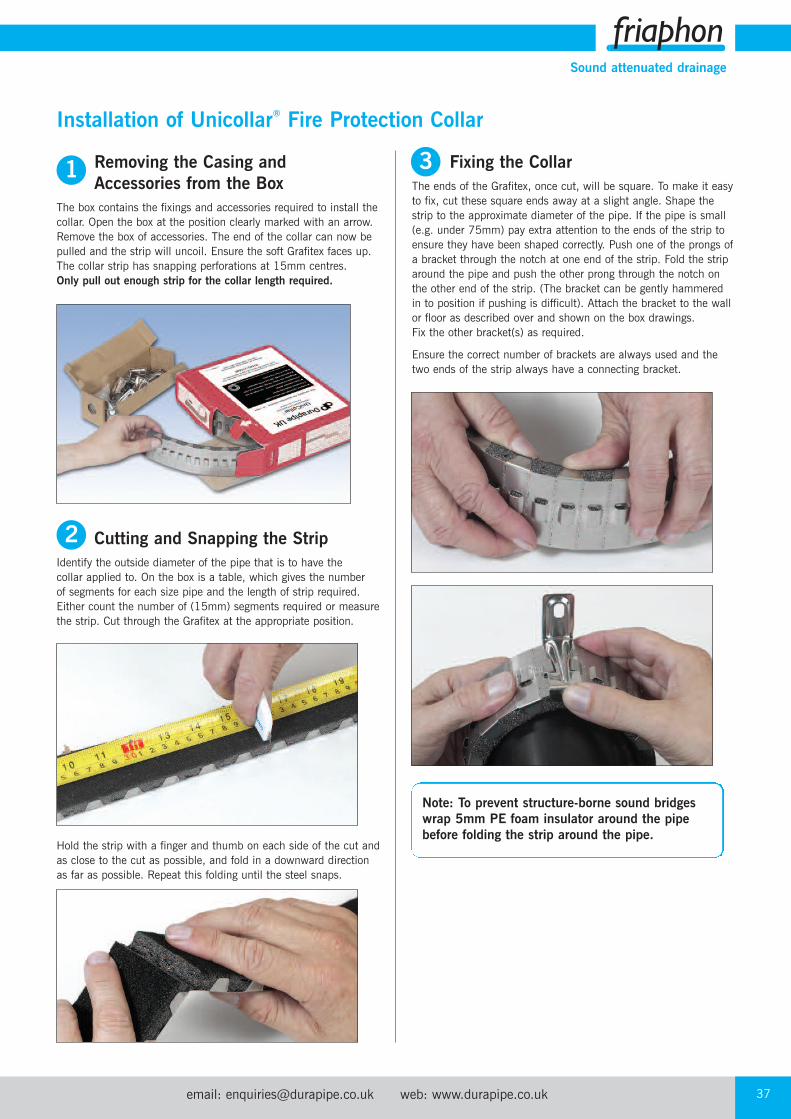
Removing the Casing and Accessories from the Box
The box contains the fixings and accessories required to install thecollar. Open the box at the position clearly marked with an arrow.Remove the box of accessories. The end of the collar can now bepulled and the strip will uncoil. Ensure the soft Grafitex faces up.The collar strip has snapping perforations at 15mm centres. Only pull out enough strip for the collar length required.
Cutting and Snapping the StripIdentify the outside diameter of the pipe that is to have the collar applied to. On the box is a table, which gives the number of segments for each size pipe and the length of strip required. Either count the number of (15mm) segments required or measurethe strip. Cut through the Grafitex at the appropriate position.
Hold the strip with a finger and thumb on each side of the cut andas close to the cut as possible, and fold in a downward directionas far as possible. Repeat this folding until the steel snaps.
Installation of Unicollar® Fire Protection Collar
Fixing the CollarThe ends of the Grafitex, once cut, will be square. To make it easyto fix, cut these square ends away at a slight angle. Shape thestrip to the approximate diameter of the pipe. If the pipe is small(e.g. under 75mm) pay extra attention to the ends of the strip toensure they have been shaped correctly. Push one of the prongs ofa bracket through the notch at one end of the strip. Fold the striparound the pipe and push the other prong through the notch onthe other end of the strip. (The bracket can be gently hammeredin to position if pushing is difficult). Attach the bracket to the wallor floor as described over and shown on the box drawings. Fix the other bracket(s) as required.
Ensure the correct number of brackets are always used and thetwo ends of the strip always have a connecting bracket.
1
2
3
Note: To prevent structure-borne sound bridgeswrap 5mm PE foam insulator around the pipebefore folding the strip around the pipe.

Tel: +44 (0)1543 279909 Fax: +44 (0)1543 27945038
Sound attenuated drainage
FloorsThe concrete must be in a condition that will ensure the anchorshold securely. Larger steel fixings may be used if deemedappropriate. Back fill any gap between the pipe and concretegreater than 8mm with mortar or commercial grade mortar mix.Acrylic, intumescent or silicone sealant may be applied around thepipe on the topside of the floor slab if a water seal is required. If there is a possibility of pipe movement occurring that will causecracks in the seal between the pipe and mortar mix (if used), it may be advisable to seal the pipe with acrylic, intumescent orsilicone sealant to prevent cold smoke egress. This however is notrequired for the fire rating to be achieved. If the gap between thepipe and slab is less than 8mm, apply a bead of acrylic,intumescent or silicone sealant approx. 8mm deep in to the gap atthe soffit.
Fire Resistance (BS 476: Part 20)
Pipe Size Integrity
110mm 2 hours
160mm 2 hours
WallsFor framed walls, use the 40mm x 10 laminating screws provided.For masonry walls, use the 20mm x 5mm steel anchors provided.The wall or floor must be in a condition that will ensure theanchors hold securely. Larger steel fixings may be used if deemedappropriate. Ensure the annular gap between the wall and pipe isminimal and seal this gap with a bead of acrylic, intumescent orsilicone sealant. Attach a collar to both faces of the wall. Fire testswere conducted with two brackets on pipes 69mm and under. Forframed walls, three brackets are recommended if framing studs arenot available to screw in to.
Fire Resistance (BS 476: Part 20)
Pipe Size Integrity
110mm 2 hours
160mm 2 hours
For details of suitability and approvals for use of Unicollar for otherpipe materials and sizes contact the technical support departmenton 01543 272446.
4
5

email: [email protected] web: www.durapipe.co.uk 39
Sound attenuated drainage
Friaphonpipe
Friaphondouble coupler
PVCu pipe
DN Friaphon Cast iron PE/PP mineral- PVCu HD PE Fibre Steelreinforced cement
100 110 110+2–1 110 110 110 116 102
150 160 160+2–2 160 160 160 168 159
Overview of outside diameter ‘d’ of other materials in mm
Flow direction
Transition to other Pipe Systems
Friaphonpipe
Friaphondouble coupler
HDPE
Friaphonpipe
Flexsealconnector
Cast iron pipe Friaphonpipe
Cast iron pipecoupling
Cast iron pipe
Friaphonpipe
Connector pieceVitrifiedclay
Friaphonpipe
Steel pipeFriaphondouble coupler

Tel: +44 (0)1543 279909 Fax: +44 (0)1543 27945040
Sound attenuated drainage
Site Work
Inspection and testingInspection and testing should be carried out in accordance with BS 12056: 2000 and Building Regulations noting especially thedetails given in respect of air testing and the fact that smoketesting of plastics pipework should be avoided as the materials can be adversely affected.
Air testThe installation should be capable of withstanding an air test of positive pressure of at least 38mm water gauge for at least three minutes. During this time every trap should maintain a water seal of at least 25mm.
HandlingFriaphon pipes are strong, though lightweight and therefore veryeasily handled. However, reasonable care should be exercisedwhile handling, particularly in extremely cold conditions. Pipesshould preferably be loaded and unloaded by hand but ifmechanical handling is used, protected slings are recommended.
RecyclabilityAll plastic components in the Friaphon domestic drainage systemare completely recyclable.
Installation OutdoorsProtect the FRIAPHON‚ product range against permanent UVradiation.
Condensate insulationFriaphon pipes do not require insulation against condensation.
Friaphon, being a thicker wall pipe constructed of 2 different layers of pipe has a much lower thermal transfer value than that of,say, cast iron and therefore condensation is less likely to form during periods of cooling.
Pipe Material Thermal Transfer ValueFriaphon 0.16 W /mk
Cast Iron 50-60 W /mk
Use water-based paint (solvent free).

email: [email protected] web: www.durapipe.co.uk 41
Sound attenuated drainage
Conformity Certificates
THE GERMAN INSTITUTE FOR CONSTRUCTION ENGINEERINGA Statutory Body
Notificationon
the Renewal of the Currency Period of the General Approval Proving Compliance Withthe Requirements Specified by the Construction Supervisory Authority
Issued on 30 January 1997
Approval number: Z-42.1-220
Subject matter of approval: Double-layer wastewater pipes and form parts withhomogeneous wall structure made of styrene copolymersDN 50 up to DN 150 of building material class B2 –normally combustible – as per DIN 4102 for in-housewastewater pipes
Currency period expires on: 30 November 2006
Fraunhofer Institute for Construction Physics
Officially acknowledged test institute for the approval of Head of Institute:new building materials, elements and methods – Research, Univ.-Prof. Dr.-Ing. habil.development, testing, demonstration and consultancy services Dr. h.c. mult. Dr. E.h. mult.in the areas of construction physics Karl Genis
P-BA 354/1998
Determination of the Noise Behaviour of a Wastewater SystemWith Fire Protection Collars
THE GERMAN INSTITUTE FOR CONSTRUCTION ENGINEERINGA Statutory Body
General Approval Proving Compliance With the RequirementsSpecified by the Construction Supervisory Authority
Approval number: Z-19.17-1271
Subject matter of approval: Fire-protective sheathing“Friaphon fire protection collar DE and NE”Fire rating R 120 and R 90 as per DIN 4102-11
Currency period expires on: 31 July 2007
1
2
3
Tel: +44 (0)1543 279909 Fax: +44 (0)1543 27945042
Sound attenuated drainage
1. DEFINITIONS:‘Seller’ shall mean Glynwed Pipe Systems Limited, registered in England under number1698059. ‘Buyer’ shall mean any company, organisation or individual to whom a quotationis offered, or whose order is accepted by the Seller.
2. CONDITIONS:All offers, quotations, estimates, acceptances and contracts are subject to theseConditions of Business and any terms or conditions which any other person shall seek toimpose or make part of any contract shall, so far as is inconsistent with these Conditionsof Business, not apply unless expressly agreed by the Seller in writing. The headings inthese conditions are for convenience only and shall not affect their interpretation.
3. QUOTATIONS AND PRICE VARIATION:a) Any quotation given by the Seller is an invitation to the Buyer to make an offer only andno order of the Buyer placed with the Seller in pursuance of a quotation or otherwise shallbe binding on the Seller unless and until it is accepted in writing by the Seller.
b) Unless stated otherwise, all quotations and published price lists are ex works, exclusiveof VAT and shall remain valid for 30 days or such a period as may be quoted butnevertheless the Seller may amend or withdraw any quotation by written or oral notice.Quotations may be varied if the Buyer makes variations in his specifications.
4. STATEMENTS OR REPRESENTATIONS TO THE BUYER:If any statement or representation has been made to the Buyer upon which the Buyerrelies other than in the documents enclosed with the Seller's quotation, the Buyer must setout that statement or representation in a document to be attached to or endorsed on theorder in which case the Seller may submit a new quotation.
5. DELIVERY - TIME:a) Any period for delivery given at any time and in any manner by the Seller is an estimateonly and is not binding on the Seller. Delivery periods are normally calculated from thelater of:
i) acceptance of order; or
ii) where applicable, the receipt by the Seller of a detailed specification or drawings.
b) Time shall not be deemed to be of the essence of the contract. Failure by the Seller tomeet any quoted delivery period for any part or the whole of the order shall not entitle theBuyer to rescind the contract or to claim damages of any nature.
c) The Seller will endeavour to comply with reasonable requests by the Buyer forpostponement of delivery but shall be under no obligation to do so. Where delivery ispostponed otherwise than due to default by the Seller the Buyer shall pay all costs andexpenses including a reasonable charge for storage and transportation occasionedthereby and an extra charge for split delivery if applicable.
d) The Buyer will receive delivery of any consignment between the hours of 8.00am and4.00pm Monday to Friday inclusive, unless otherwise agreed in writing. Cost incurred bythe Seller arising from the Buyer's refusal to accept consignments within the agreed hoursshall be borne by the Buyer.
6. DELIVERY AND RISK:a) Except where stated to the contrary in the contract, delivery shall be made as follows:
i) where the Buyer provides the transport, delivery shall be made ex the Seller's works;
ii) where the Seller provides the transport, delivery shall be made to the premises of theBuyer, or the premises of the Buyer's customer or works site if the Buyer has requested delivery to be so made but where the Buyer has made such a request the Seller will make a first delivery to the Buyer's customer or works site as so much of the goods as is available for that delivery but subsequent deliveries will be made to the premises of the Buyer.
b) The Seller may at its discretion make partial delivery of orders and invoice the same.
c) Risk in the goods shall pass on delivery.
d) Where goods are sent FOB the Seller's responsibility shall cease when the goods areplaced on board ship or aircraft without the need for the Seller to give notice to the Buyerand the provisions of Section 32(3) of the Sale of Goods Act 1979 shall not apply.
7. OWNERSHIP OF GOODS:a) The goods shall remain the sole and absolute property of the Seller as legal andequitable owner until such time as the Buyer shall have paid to the Seller the contract pricetogether with the full price of any other goods the subject of any contract between theSeller and the Buyer.
b) The Buyer acknowledges that until such time as the property in the goods passes to theBuyer he is in possession of the goods as a bailee and fiduciary agent for the Seller andthe Purchaser shall store the goods in such a manner that they are clearly identifiable asthe property of the Seller.
c) Until payment due under all contracts between the Buyer and the Seller had been madein full, in the event of sale of the goods by the Buyer:i) the Seller shall be entitled to trace all proceeds of sale received by the Buyer through
any bank or other account maintained by the Buyer; and
ii) the Buyer shall if requested by the Seller in writing to so assign its rights to recover theselling price of the goods from the third parties concerned. Such monies to be held separately by the Buyer as agent on behalf of the Seller.
d) The Seller may for the purpose of recovery of its goods enter upon any premises wherethey are stored or where they are reasonably thought to be stored and may repossess thesame.
8. TERMS OF PAYMENT:In the event of default in payment according to the agreed payment terms between theSeller and the Buyer – i.e. by the end of the month following the month of despatch of thegoods the Seller shall be entitled without prejudice to any other right or remedy to suspendall further deliveries and to charge interest on any amount outstanding at the rate of 2%per month until payment in full is made (a part of a month being treated as a full month forthe purpose of calculating interest).
9. SHORTAGES AND DEFECTS APPARENT ON DELIVERY:a) It shall be the responsibility of the Buyer to inspect or arrange for an inspection of thegoods on delivery whether the goods are delivered to the Buyer's premises or to thepremises of the Buyer's customer or to a works site. If no such inspection is made theBuyer shall be deemed to have accepted the goods.
b) The Buyer shall have no claim for shortages or defects apparent on inspection unless:
i) a written complaint is made to the Seller within three days of receipt of the goods specifying the shortage or defect; and
ii) the Seller is within seven days of receipt of the complaint given an opportunity to inspect the goods and investigate the complaint before any use is made of the goods.
c) If a complaint is not made to the Seller as herein provided then in respect of suchshortages or defects the goods shall be deemed to be in all respects in accordance withthe contract and the Buyer shall be bound to pay for the same accordingly.
10. CLAIMS FOR DEFECTS NOT APPARENT ON INSPECTION:a) The Buyer shall have no claim for defects not apparent on inspection unless the Selleris notified of defective workmanship or materials within twelve months from delivery of thegoods. Provided that the goods have been installed and applied in accordance with anyrelevant recommendations made by the Seller, the Seller will at its option replace thegoods or refund the net invoiced price in respect of the goods which have been shown tobe defective. If the Seller does so supply substitute goods the Buyer shall be bound toaccept such substituted goods in full satisfaction of the obligations of the Seller under thecontract.
b) The Buyer shall in any event have no claim or set-off in respect of defects unless awritten complaint is sent to the Seller as soon as the defect is noticed and no use is madeof the goods thereafter or alteration made thereto by the Buyer before the Seller is givenan opportunity to inspect the goods.
c) The Buyer is responsible for ensuring that the goods are fit for any particular purpose,and no warranty or condition of fitness for any particular purpose is to be implied into thecontract.
11. LIABILITY:Save as stated in Conditions 9 and 10 (and save in respect of death or personal injuryresulting from the negligence of the Seller its servants or agents) the Seller shall not beliable for any claim or claims for direct or indirect consequential or incidental injury loss ordamage made by the Buyer against the Seller whether in contract or in tort (includingnegligence on the part of the Seller its servants or agents) arising out of or in connectionwith any defect in the goods or their fitness or otherwise for any particular purpose or anyact omission neglect or default of the Seller its servants or agents in the performance ofthe contract.
12. FORCE MAJEURE:Notwithstanding anything herein contained neither the Buyer nor the Seller is to be heldliable for any delay or failure to carry out the contract due wholly or in part to an act of Godaction by any Government whether British or foreign civil war strikes and/or lockoutswheresoever occurring fire trade disputes floods or unfavourable weather or any materialbecoming unavailable or irreplaceable (whether at all or at commercially acceptableprices) or any other circumstances beyond the control of the Seller.
13. SUB-CONTRACTING:The Seller reserves the right to sub-contract the fulfilment of any order or any part thereof.
14. INSOLVENCY AND BREACH OF CONTRACT:In the event that:
a) the Buyer commits any breach of the contract and fails to remedy such breach (if capable of remedy) within a period of thirty days from receipt of a notice in writing fromthe Seller requesting such remedy; or
b) any distress or execution is levied upon any of the goods or property of the Buyer; or
c) the Buyer offers to make any arrangements with or for the benefit of its creditors or (if an individual) becomes subject to a petition for a bankruptcy order or (being a limitedcompany) has a receiver appointed of the whole or any part of its undertaking property orassets; or
d) an order is made or a resolution is passed or analogous proceedings are taken for thewinding up of the Buyer (save for the purpose of reconstruction or amalgamation withinsolvency and previously approved in writing by the Seller) the Seller shall thereupon beentitled without prejudice to its other rights hereunder forthwith to suspend all furtherdeliveries until the default has been made good or to determine the contract and anyunfulfilled part thereof or at the Seller's option to make partial deliveries. Notwithstandingany such termination the Buyer shall pay to the Seller at the contract rate for all the goodsdelivered up to and including the date of termination.
15. INDUSTRIAL PROPERTY RIGHTS:If goods supplied by the Seller to the Buyer's design or specifications infringe or arealleged to infringe any patent or registered design right or copyright the Buyer willindemnify the Seller against all damages, costs and expenses incurred by the Seller as aresult of the infringement or allegation. The Buyer will give the Seller all possible help inmeeting any infringement claim brought against the Seller.
16. BUYER'S ERROR IN ORDERING:In the event the Buyer orders incorrectly the Seller will be under no obligation to the Buyerto rectify or assist in rectifying the error.
17. LAW AND JURISDICTION:The contract shall be subject in all respects to English Law and to the jurisdiction of theEnglish Courts.
DURAPIPE UK CONDITIONS OF SALE
Terms and Conditions

Distributor
04900306 November 2009
an company
Registered office:
Durapipe UKWalsall Road Norton CanesCannockStaffordshireWS11 9NSUnited KingdomTel: +44 (0)1543 279909Fax: +44 (0)1543 279450email: [email protected]: www.durapipe.co.uk
Durapipe UK reserves the right to modify the details in this publication as products and specifications are updated and improved.The content of this publication is for general information only and it is the user’s responsibility to determine the suitability of any productfor the purpose intended.
For further information on all Durapipe UK products and services contact our Customer Services Department as detailed below.
Customer Services Tel: 01543 273100 Fax: 0800 317875
Durapipe UK is a trade name of Glynwed Pipe Systems Ltd. Company Number 1698059.