TECHNICAL CONTENTS - Cape Dory Yachts CONTENTS INFORMATION. SUBJECT: Tappet Adjustment ... A number...
65
T.I. No. Issue Subject Products Affected Date Gn 001 1 Tappet Adjustment Perkins 1000 Series Engines Mar. 90 Gn 002 1 Rocker Shaft Security Perkins 1000 Series Engines July 90 Gn 003 1 Crankshaft Rear Main Oil Seal & Housing Perkins 1000 Series Engines Mar. 91 Gn 004 1 Turbocharger Fault Diagnosis Perkins 1000 Series Engines Dec. 91 Gn 005 1 Health & Safety Recommendations - Fluoroelastomeric Materials All Mar. 92 Gn 006 1 Turbochargers Turbocharged Perkins 90 BHP Feb. 93 Gn 007 1 Piston & Piston Ring Improvements 4 cyl. Turbocharged Engines Feb. 93 Gn 008 1 Alternator Connections on Mainframe Harness Perkins Engines as applicable Nov. 93 Gn 009 1 Low Sulphur Fuels Perkins 1000 Series Engines Mar. 94 Gn 010 1 Brake Master Cylinder Kits As Detailed on Bulletin Mar. 94 Gn 011 1 Hydraulic Ram Identification Jun. 94 Gn 012 1 Oil Pump - Idler Gear Perkins 1000 Series Engines July 94 Gn 013 1 Stake Nuts, Input and Output Flanges All ITL Transmissions & Axles Feb. 95 Gn 014 1 Fuel Injection Pump - Seal Failure Perkins 1000 Series Engines Aug. 95 Gn 015 1 Engine Lubrication System - Relief Valve Housing Perkins 1000 Series Engines Feb. 96 Gn 016 1 Parkbrake Clevis Pin Improvements Trans. with Clysdale Park Brake Feb. 96 Gn 017 1 Starter Motors All Perkins Engines Mar. 96 Gn 018 2 Magneti Marelli Service/Warranty Support All Perkins Engines Feb. 99 Gn 019 2 Service Department - Computer Diagnostic Equipment Dec. 98 Gn 020 1 Engine Workshop Manuals Perkins New 1000 Series April 98 Gn 021 1 Axle Propshafts All machine installations April 98 Gn 022 1 Engine Silencer Improvements Perkins Engines Nov. 90 Gn 023 1 Change of position, exhaust manifold bushes New Perkins 1000 Series Oct. 98 Gn 024 1 Pin Timed Fuel Injection Pumps All Perkins New 1000 Series Jan. 99 Gn 025 1 Improved Oil Cooler with Pressed Steel Cover All Perkins 1000 Series Jan. 99 Gn 026 1 Introduction of Wear Sleeve for Front Oil Seal Perkins 4.236 & 1000 Series Feb. 99 Gn 027 1 Washers for Fuel Injection Pump Gear New Perkins 1000 Series Feb. 99 Gn 028 1 Improved Exhaust Valve Guide New Perkins 1000 Series Feb. 99 Gn 029 1 ITL Hydraulic Hose Fittings and O-rings All ITL Products Mar. 99 Gn 030 1 Perkins Low Emission Diesel Engine New Perkins 1000 Series Apr. 99 Gn 031 1 Hydraulic Ram Sealing Procedure All Machines with ITL Rams Nov. 99 Gn 032 1 Oil Control Rings 1000 Series models AR & AS Jan. 01 Gn 033 1 Plastic Thermostat Housings All Perkins 1000 Series Jan. 01 Gn 034 1 Introduction of Improved Fuel Lift Pump All Perkins 1000 Series Feb. 01 Gn 035 1 Coolant Pressure Cap All Perkins 1000 Series Apr. 01 Gn 036 1 Engine Oil Consumption Perkins Low Emission Engines Apr. 01 Gn 037 1 Engine Rocker Cover Perkins Low Emission Engines May 01 Gn 038 1 New ITL NAPSC Network New North American Network Jan. 02 Gn 039 1 Safety Precautions When an Engine is Cleaned All Engines Sep. 02 GENERAL T.I. BULLETIN INDEX Click on bulletin title to view DATE: DEC '02 PAGE 1 OF 1 ISSUE: 8 CONTENTS TECHNICAL INFORMATION
Transcript of TECHNICAL CONTENTS - Cape Dory Yachts CONTENTS INFORMATION. SUBJECT: Tappet Adjustment ... A number...

T.I. No. Issue Subject Products Affected Date
Gn 001 1 Tappet Adjustment Perkins 1000 Series Engines Mar. 90Gn 002 1 Rocker Shaft Security Perkins 1000 Series Engines July 90Gn 003 1 Crankshaft Rear Main Oil Seal & Housing Perkins 1000 Series Engines Mar. 91Gn 004 1 Turbocharger Fault Diagnosis Perkins 1000 Series Engines Dec. 91Gn 005 1 Health & Safety Recommendations -
Fluoroelastomeric Materials All Mar. 92Gn 006 1 Turbochargers Turbocharged Perkins 90 BHP Feb. 93Gn 007 1 Piston & Piston Ring Improvements 4 cyl. Turbocharged Engines Feb. 93Gn 008 1 Alternator Connections on Mainframe Harness Perkins Engines as applicable Nov. 93Gn 009 1 Low Sulphur Fuels Perkins 1000 Series Engines Mar. 94Gn 010 1 Brake Master Cylinder Kits As Detailed on Bulletin Mar. 94Gn 011 1 Hydraulic Ram Identification Jun. 94Gn 012 1 Oil Pump - Idler Gear Perkins 1000 Series Engines July 94Gn 013 1 Stake Nuts, Input and Output Flanges All ITL Transmissions & Axles Feb. 95Gn 014 1 Fuel Injection Pump - Seal Failure Perkins 1000 Series Engines Aug. 95Gn 015 1 Engine Lubrication System - Relief Valve Housing Perkins 1000 Series Engines Feb. 96Gn 016 1 Parkbrake Clevis Pin Improvements Trans. with Clysdale Park Brake Feb. 96Gn 017 1 Starter Motors All Perkins Engines Mar. 96Gn 018 2 Magneti Marelli Service/Warranty Support All Perkins Engines Feb. 99Gn 019 2 Service Department - Computer Diagnostic Equipment Dec. 98Gn 020 1 Engine Workshop Manuals Perkins New 1000 Series April 98Gn 021 1 Axle Propshafts All machine installations April 98Gn 022 1 Engine Silencer Improvements Perkins Engines Nov. 90Gn 023 1 Change of position, exhaust manifold bushes New Perkins 1000 Series Oct. 98Gn 024 1 Pin Timed Fuel Injection Pumps All Perkins New 1000 Series Jan. 99Gn 025 1 Improved Oil Cooler with Pressed Steel Cover All Perkins 1000 Series Jan. 99Gn 026 1 Introduction of Wear Sleeve for Front Oil Seal Perkins 4.236 & 1000 Series Feb. 99Gn 027 1 Washers for Fuel Injection Pump Gear New Perkins 1000 Series Feb. 99Gn 028 1 Improved Exhaust Valve Guide New Perkins 1000 Series Feb. 99Gn 029 1 ITL Hydraulic Hose Fittings and O-rings All ITL Products Mar. 99Gn 030 1 Perkins Low Emission Diesel Engine New Perkins 1000 Series Apr. 99Gn 031 1 Hydraulic Ram Sealing Procedure All Machines with ITL Rams Nov. 99Gn 032 1 Oil Control Rings 1000 Series models AR & AS Jan. 01Gn 033 1 Plastic Thermostat Housings All Perkins 1000 Series Jan. 01Gn 034 1 Introduction of Improved Fuel Lift Pump All Perkins 1000 Series Feb. 01Gn 035 1 Coolant Pressure Cap All Perkins 1000 Series Apr. 01Gn 036 1 Engine Oil Consumption Perkins Low Emission Engines Apr. 01Gn 037 1 Engine Rocker Cover Perkins Low Emission Engines May 01Gn 038 1 New ITL NAPSC Network New North American Network Jan. 02Gn 039 1 Safety Precautions When an Engine is Cleaned All Engines Sep. 02
GENERAL T.I. BULLETIN INDEXClick on bulletin title to view
DATE: DEC '02 PAGE 1 OF 1 ISSUE: 8
CONTENTS
TECHNICALINFORMATION

SUBJECT: Tappet Adjustment
PRODUCTS AFFECTED: All Perkins 1000 series Engines
TO BE CARRIED OUT: At Next Service / As Required
SERVICE PROCEDURE:
When tappet adjustment is required, it is important to re-torque the adjusting screw lock nut A. If this is not correctlyactioned the adjusting screw will become loose which could cause damage to the tappet assembly and push rod.
Lock Nut Torque - 20 lbs ft.
Page 1 of 1
! SAFETY NOTICE - Instructions in the Service Bulletins assume that theengineer has a sound knowledge of safety procedures and has been trained in themaintenance and repair of ITL equipment. If you are unsure or do not understandinformation contained in the Service Bulletins then ask your supervisor for advice.Remember SAFETY MUST COME FIRST.
Number Gn001(JCB Gen 003)
Issue 1Date March 1990
GeneralTECHNICALINFORMATION
INDEX
THIS BULLETIN IS ISSUED FOR THE PURPOSE OF CIRCULATING TECHNICAL INFORMATION AND DOESNOT CONSTITUTE AN INSTRUCTION TO CARRY OUT WARRANTY REPAIRS ON MACHINES
ISSUED BY THE TECHNICAL SERVICE DEPARTMENT OF I.T.L., WREXHAM, CLWYD, LL13 9UF, UNITED KINGDOM

SUBJECT: Rocker Shaft Security
PRODUCTS AFFECTED: All Perkins 1000 Series Engines
TO BE CARRIED OUT: Information Only
SERVICE INFORMATION:
Introduction of new fasteners for the rocker assembly.
SERVICE PROCEDURE:
Flanged nuts A replace the three nuts and washers securing the rocker shaft to the cylinder head. The single bolt andwasher is replaced by a flanged bolt.
If the new fasteners are fitted to earlier engines the washers must be removed.
Torque tighten the new fasteners to 40 Nm (30 lbf ft).
PARTS INFORMATION
Cut-in from engine serial number U544908U.
02/291060 NUT replaces 1370/0401Z
02/291048 SET SCREW replaces 02/291125
02/291064 WASHER - Not Required
Page 1 of 1
! SAFETY NOTICE - Instructions in the Service Bulletins assume that theengineer has a sound knowledge of safety procedures and has been trained in themaintenance and repair of ITL equipment. If you are unsure or do not understandinformation contained in the Service Bulletins then ask your supervisor for advice.Remember SAFETY MUST COME FIRST.
Number Gn002(JCB Gen 005)
Issue 1Date July 1990
GeneralTECHNICALINFORMATION
INDEX
THIS BULLETIN IS ISSUED FOR THE PURPOSE OF CIRCULATING TECHNICAL INFORMATION AND DOESNOT CONSTITUTE AN INSTRUCTION TO CARRY OUT WARRANTY REPAIRS ON MACHINES
ISSUED BY THE TECHNICAL SERVICE DEPARTMENT OF I.T.L., WREXHAM, CLWYD, LL13 9UF, UNITED KINGDOM

SUBJECT: Crankshaft Rear Main Oil Seal and Housing
PRODUCTS AFFECTED: All Perkins 1000 Series Engines
TO BE CARRIED OUT: Information Only
A number of reports by Perkins have been received concerning crankshaft rear main oil seal leaks. Little or no detailis completed in the comments section of the warranty claim form. Information given in the comments section willenable Perkins to identify the exact fault and take the correct remedial action.
The following instructions will enable you to locate and rectify the exact fault, this fault should then be stated in thecomments section of all warranty claims, failure to do so will invalidate the warranty claim.
REAR OIL SEAL/HOUSING
If oil is leaking past the rear seal, oil will normally be found inside the flywheel housing with some evidence of leakagefrom the low inspection plate.
To rectify
1 Remove the transmission.
2 Remove the flywheel using guide studs (remove twodiametrically opposite bolts and temporarily fit guidestuds).
3 Remove seal housing B setscrews. Using anappropriate lever gently pry the seal housing awayfrom cylinder block, taking care not to damage thehousing.
4 Press out old seal and fit replacement, using toolnumber PD.145D (see Perkins Service Manual), thiswill pre-set the seal depth as required.
Note: The service tool will set seal to 4 different depths, on new engines position 1 should be used.
5 Make sure that the two dowels C are fitted in the cylinder block. PUT A NEW JOINT in position on the dowels.
6 Put the seal guide A on the crankshaft flange. Lubricate the crankshaft flange, the seal lip and the seal guide withclean engine oil.
7 Put the seal housing B complete with seal on the seal guide A (PD.145D). Carefully push the assembly intoposition on the crankshaft flange and onto the two dowels C. Remove the seal guide, fit and torque the housingsecuring setscrews M8 to 22 Nm (16 lbf ft) and the capscrews M8 to 18 Nm (13 lbf ft).
8 Refit flywheel using guide studs and torque retaining bolts to 105 Nm (77 lbf ft).
Page 1 of 3
! SAFETY NOTICE - Instructions in the Service Bulletins assume that theengineer has a sound knowledge of safety procedures and has been trained in themaintenance and repair of ITL equipment. If you are unsure or do not understandinformation contained in the Service Bulletins then ask your supervisor for advice.Remember SAFETY MUST COME FIRST.
Number Gn003(JCB Gen 010)
Issue 1Date March 1991
GeneralTECHNICALINFORMATION
INDEX
THIS BULLETIN IS ISSUED FOR THE PURPOSE OF CIRCULATING TECHNICAL INFORMATION AND DOESNOT CONSTITUTE AN INSTRUCTION TO CARRY OUT WARRANTY REPAIRS ON MACHINES
ISSUED BY THE TECHNICAL SERVICE DEPARTMENT OF I.T.L., WREXHAM, CLWYD, LL13 9UF, UNITED KINGDOM

Page 2 of 3 Gn003 Issue 1
OIL LEAKAGE FROM REAR OF ENGINE
When investigating oil leakage at the rear of the engine the following areas should be checked and corrected as foundnecessary.
1 Main Oil Gallery Plug/Washer
A leak from this area can usually be identified by a trace of oilalong the contact face of block and flywheel housing on thefuel pump side of the engine.
This can be rectified as follows
1.1 Remove the transmission.
1.2 Remove the flywheel using guide studs (remove twodiametrically opposite bolts and temporarily fit guide
1.3 Removethe starter motor.
1.4 Remove the flywheel housing (it may be necessary totap the housing using a soft hammer to disengagethe housing dowels).
1.5 Remove the threaded gallery plug D located top leftof cylinder block using appropriate allen key.
1.6 Fit a new plug/washer using Loctite 574 Multigasketand torque to 85 Nm (62.5 lbf ft).
1.7 Refit flywheel housing and torque securing screwsM10 to 44 Nm (33 lbf ft) and M12 to 75 Nm (55 lbf ft).
1.8 Refit flywheel using guide studs and torque retaining bolts to 105 Nm (77 lbf ft).
2 Camshaft Rear End Plug
Leakage from the cam end plug will normally produce a trace of oil at the contact face between block and flywheelhousing on the manifold side.
To rectify:
2.1 Remove the transmission.
2.2 Remove the flywheel using guide studs (remove two diametrically opposite bolts and temporarily fit guidestuds).
2.3 Remove the starter motor.
2.4 Remove the flywheel housing (it may be necessary to tap the housing using a soft hammer to disengage thehousing dowels).
2.5 Remove camshaft end plug E located top right of the cylinder block.
2.6 Fit new plug using Loctite 574 Multigasket.
2.7 Refit flywheel housing and torque securing screws M10 to 44 Nm (33 lbf ft) and M12 to 75 Nm (55 lbf ft)
2.8 Refit flywheel using guide studs and torque retaining bolts to 105 Nm (77 lbf ft).
Page 3 of 3 Gn003 Issue 1
OIL LEAKAGE FROM REAR OF ENGINE (cont’d)
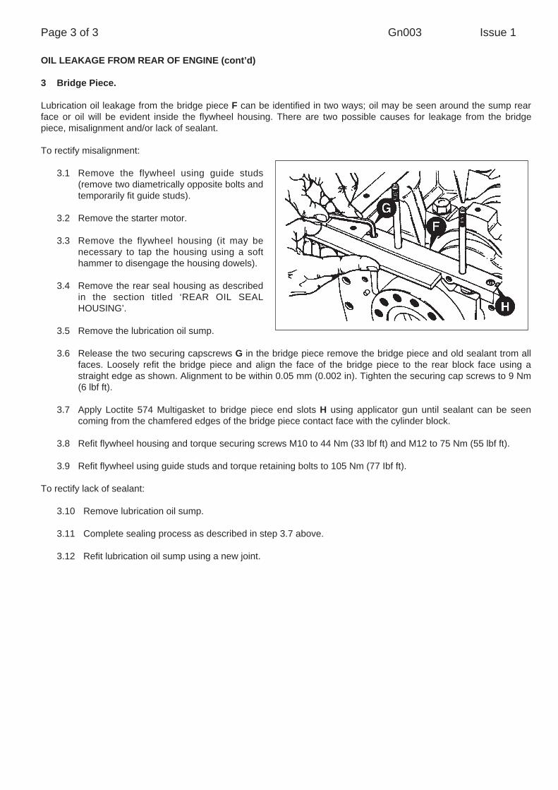
3 Bridge Piece.
Lubrication oil leakage from the bridge piece F can be identified in two ways; oil may be seen around the sump rearface or oil will be evident inside the flywheel housing. There are two possible causes for leakage from the bridgepiece, misalignment and/or lack of sealant.
To rectify misalignment:
3.1 Remove the flywheel using guide studs(remove two diametrically opposite bolts andtemporarily fit guide studs).
3.2 Remove the starter motor.
3.3 Remove the flywheel housing (it may benecessary to tap the housing using a softhammer to disengage the housing dowels).
3.4 Remove the rear seal housing as describedin the section titled ‘REAR OIL SEALHOUSING’.
3.5 Remove the lubrication oil sump.
3.6 Release the two securing capscrews G in the bridge piece remove the bridge piece and old sealant trom allfaces. Loosely refit the bridge piece and align the face of the bridge piece to the rear block face using astraight edge as shown. Alignment to be within 0.05 mm (0.002 in). Tighten the securing cap screws to 9 Nm(6 lbf ft).
3.7 Apply Loctite 574 Multigasket to bridge piece end slots H using applicator gun until sealant can be seencoming from the chamfered edges of the bridge piece contact face with the cylinder block.
3.8 Refit flywheel housing and torque securing screws M10 to 44 Nm (33 lbf ft) and M12 to 75 Nm (55 lbf ft).
3.9 Refit flywheel using guide studs and torque retaining bolts to 105 Nm (77 Ibf ft).
To rectify lack of sealant:
3.10 Remove lubrication oil sump.
3.11 Complete sealing process as described in step 3.7 above.
3.12 Refit lubrication oil sump using a new joint.

SUBJECT: Turbocharger Fault Diagnosis
PRODUCTS AFFECTED: All Perkins Turbo Engines (AB and AC Builds)
TO BE CARRIED OUT: Information Only
A number of turbochargers have been replaced unnecessarily. When inspected by the supplier, no fault has beenfound or the fault differs from the failure code and/or description on the claim.
Service Procedure
1 To assist in the correct diagnosis of general faults, please refer to the attached fault finding charts.
2 Fuel Starting Aid (Thermostart)
A problem has occurred several times where the inside of the induction manifold has been found to be wet andthe turbocharger has been returned as faulty. After investigation, the turbocharger was found to have no fault.
If the inside of the induction manifold is wet, check that there is not a fuel leak from the fuelled starting aid (if fitted):
2.1 How to check the fuelled starting aid
2.1.1 Disconnect the fuel pipe A and the electricalconnector B at the starting aid C. Remove thestarting aid from the manifold and fit a suitable plugin the manifold.
2.1.2 Connect the fuel pipe to the starting aid, but leavethe union nutconnection loose. Do not fit theelectrical connection, but ensure that the connectoris covered with a suitable insulator. Operate thelever of the fuel lift pump until fuel free of air -comes from the union nut connection.Tighten theunion nut at the starting aid.
2.1.3 Start the engine and operate it at low speed. Checkthat there is no fuel leakage from the valve of thestarting aid.
2.1.4 If there is no leakage, remove the plug from theinduction manifold and fit the starting aid. Connectthe fuel pipe to the starting aid and remove the airfrom the pipe as described above. Connect theelectrical connector to the starting aid.
2.1.5 If there is a leak from the valve of the starting aid, fit a new starting aid.
3 Warranty Claim Procedure
All Perkins warranty claims must state clearly the symptom and cause in the comments section of the claim form.If there is insufficient space on the claim form, then attach a written report. Failure to follow this procedure mayresult in the warranty claim being rejected.
Page 1 of 3
! SAFETY NOTICE - Instructions in the Service Bulletins assume that theengineer has a sound knowledge of safety procedures and has been trained in themaintenance and repair of ITL equipment. If you are unsure or do not understandinformation contained in the Service Bulletins then ask your supervisor for advice.Remember SAFETY MUST COME FIRST.
Number Gn004(JCB Gen 013)
Issue 1Date Dec. 1991
GeneralTECHNICALINFORMATION
INDEX
THIS BULLETIN IS ISSUED FOR THE PURPOSE OF CIRCULATING TECHNICAL INFORMATION AND DOESNOT CONSTITUTE AN INSTRUCTION TO CARRY OUT WARRANTY REPAIRS ON MACHINES
ISSUED BY THE TECHNICAL SERVICE DEPARTMENT OF I.T.L., WREXHAM, CLWYD, LL13 9UF, UNITED KINGDOM

Page 2 of 3 Gn004 Issue 1
Fault Finding Charts
Items A to O below describe possible general faults associated with turbochargers. Opposite the faults is a columntitled ‘Possible Causes Code Numbers’; these code numbers refer to a description of possible cause(s) associatedwith the fault. The descriptions for possible causes can be found on page 3.
FAULT POSSIBLE CAUSES CODE NUMBERS
A. Not enough power 1,4,5,6.7,8,9,10,11,18,20,21, 22,25,26,27,28,34,35,36
B. Black smoke 1,4,5,6,7,8,9,10,11,18,20,21, 22,25,26,27,28,34,35,36
C. Blue smoke 1,2,4,6,8,9,17,19,20,21,22, 30,31,32,34
D. High lubricating oil consumption 2,8,15,17,19,20,28,29,31,32,34
E. Too much lubricating oil at turbine end 2,7,8,17,19,20,22,28,30,31,32
F. Too much lubricating oil at compressor end 1,2,4,5,6,8,19,20,21,28,31,32
G. Not enough lubrication 8,12,14,15,16,23,24,29,32,33, 37,38
H. Lubricating oil in the exhaust manifold 2,7,17,18,19,20,22,28,31,32
I. Inside of the induction manifold wet 1,2,3,4,5,6,8,10,11,17,18,19, 20,21,28,32,34,39,40
J. Damaged compressor impellor 3,4,6,8,12,15,16,20,21,23,24, 29,32,33,37,38
K. Damaged turbine rotor 7,8,12,13,14,15,16,18,20,22, 23,24,25,27,29,32,33,37,38
L. Rotating assembly does not turn freely 3,6,7,8,12,13,14,15,16,18,20, 21,22,23,24,29,32,33,37,38
M. Worn - bearings, bearing bores, journals 6,7,8,12,13,14,15,16,23,24, 29,33,37,38
N. Noise from turbocharger 1 , 3, 4, 5, 6, 7, 8, 9,10, 1 1 ,12,13,14,15,16,18,20,21,22,23,24, 29,32,33,34,37,38
O. Sludge or carbon deposit in bearing housing 2, 1 1, 13, 14, 15, 1 7, 18, 24, 29, 33, 37, 38

Page 3 of 3 Gn004 Issue 1
Fault Finding Charts (cont’d)
DESCRIPTION OF POSSIBLE CAUSES/SYMPTOM
1. Element of the air filter dirty
2. Restricted crankcase breather
3. Element of the air filter missing, leaking, or not sealing correctly. Loose connection to turbocharger.
4. Internal distortion or restriction in pipe from air filter to turbocharger.
5. Damaged/restricted crossover pipe - turbocharger to induction manifold.
6. Restriction between air filter and turbocharger.
7. Restriction in exhaust system.
8. Turbocharger loose or clamps/setscrews loose.
9. Induction manifold cracked or loose, flanges distorted.
10. Exhaust manifold cracked or loose, flanges distorted.
11. Restricted exhaust system.
12. Delay of lubricating oil to turbocharger at engine start.
13. Insufficient lubrication.
14. Dirty lubricating oil.
15. Incorrect lubricating oil.
16. Restricted lubricating oil supply pipe.
17. Restricted lubricating oil drain pipe.
18. Turbine housing damaged or restricted.
19. Leakage from turbocharger seals.
20. Worn turbocharger bearings.
21. Excessive dirt in compressor housing.
22. Excessive carbon behind turbine rotor.
23. Engine speed raised too rapidly at initial start.
24. Insufficient engine idle period.
25. Faulty fuel injection pump.
26. Worn or damaged atomisers.
27. Valves burned.
28. Worn piston rings.
29. Lubricating oil leakage from supply pipe.
30. Excessive preservation fluid (on initial engine start).
31. Excessive engine idle period.
32. Restriction in turbocharger bearing housing.
33. Restriction in lubricating oil filter.
34. Wet type air cleaner: Restricted, dirly element, viscosity of oil too low/high.
35. Wastegate (if fitted) actuator faulty or damaged.
36. Wastegate (if fitted) valve not free.
37. Engine stopped too soon from high load.
38. Insufficient lubricating oil.
39. Fuel leakage from fuelled starting aid.
40. Crack in backplate of compressor.
SUBJECT: HEALTH & SAFETY RECOMMENDATIONS - FLUOROELASTOMERIC MATERIALS
PRODUCTS AFFECTED: ALL
! WARNINGDue to recent publicity regarding the potential hazards associated with the handling of fluoroelastomeric materials(‘Viton’, ‘Fluorel’, ‘Technoflon’, etc.), commonly used in the production of oil seals and gaskets for the automotiveindustry, the following health and safety statement should be noted.
Note: Examples of the use of these materials on ITL products are the ‘Viton’ crankshaft oil seals on Perkins enginesand ‘Viton’ shaft and brake seals in the axles.
New Components
The normal handling of new cured fluoroelastomeric components at ambient temperature presents no known hazardand requires no special handling precautions.
Removal of Old Components during Servicing
No special precautions are required when handling old fluoroelastomeric material that has been subjected only tonormal service conditions. However, before removal, a preliminary visual examination should establish whethernormal service temperatures have been exceeded giving rise to thermal degradation. If evidence of decomposition(charring etc.) is found, the material and surrounding areas should not be touched without observing the precautionsdetailed below.
Removal of Old Material Subjected to Abnormally Hiqh Temperatures
At temperatures in excess of 300° C, e.g. engine fires, fluoroelastomeric materials can decompose, producing smallbut significant amounts of hydrofluoric acid. This acid is highly corrosive and will cause SEVERE BURNS if in contactwith the skin.
Vehicles or components that have been subjected to abnormally high temperatures should be subjected to thefollowing decontamination procedure which must be conducted by competent personnel. This will require the use ofappropriate safety equipment (neoprene rubber or heavy duty gloves, plus special safety glasses are essential).
1 Ensure that components have cooled then carefully remove and transfer suspect material to plastic bags.
2 Wash the contaminated area with a 10% calcium hydroxide or other suitable alkali solution, if necessary usingwire wool to remove residual adherent decomposition products.
3 Thoroughly wash contaminated area with detergent and water.
cont’d
Page 1 of 2
! SAFETY NOTICE - Instructions in the Service Bulletins assume that theengineer has a sound knowledge of safety procedures and has been trained in themaintenance and repair of ITL equipment. If you are unsure or do not understandinformation contained in the Service Bulletins then ask your supervisor for advice.Remember SAFETY MUST COME FIRST.
Number Gn005(JCB Gen 002)
Issue 1Date March 1992
GeneralTECHNICALINFORMATION
INDEX
THIS BULLETIN IS ISSUED FOR THE PURPOSE OF CIRCULATING TECHNICAL INFORMATION AND DOESNOT CONSTITUTE AN INSTRUCTION TO CARRY OUT WARRANTY REPAIRS ON MACHINES
ISSUED BY THE TECHNICAL SERVICE DEPARTMENT OF I.T.L., WREXHAM, CLWYD, LL13 9UF, UNITED KINGDOM

Page 2 of 2 Gn005 Issue 1
4 Place all removed material, protective gloves and wire wool used in the operation, in sealed plastic bags prior tolandfill disposal in accordance with Local Authority Regulations.
5 Fluoroelastomeric materials should NOT be incinerated.
If there is contamination of the skin or eyes, wash the affected area with a continuous supply of clean water or withcalcium hydroxide solution for 15-60 minutes. Obtain immediate medical attention.

SUBJECT: Turbochargers
PRODUCTS AFFECTED: Turbocharged Perkins (90 BHP) Engines
TO BE CARRIED OUT: Information Only
SERVICE INFORMATION:From engine serial number No. AB50440U610051X (28/1/93), a 'Garret' turbocharger is fitted; this replaces the'Schwitzer' unit. The Garret turbocharger gives improved service reliability.
SERVICE PROCEDURE:If for any reason a warranty repair is to be completed on the turbo unit, then a full written report on the repair/faultmust be submitted with the claim or the Perkins Service Information. ITL T.I. Gn004 can be used to aid fault diagnosisand specifying the fault.
Perkins dealers should carry out this work.
Failure to follow this instruction may result in the claim being rejected.
PARTS INFORMATIONDESCRIPTION PART NO. COMMENTS
'Garret' Unit 02/200460 was 'Schwitzer' unit - part no. 02/200340 (applicable to 90BHP only)
Page 1 of 1
! SAFETY NOTICE - Instructions in the Service Bulletins assume that theengineer has a sound knowledge of safety procedures and has been trained in themaintenance and repair of ITL equipment. If you are unsure or do not understandinformation contained in the Service Bulletins then ask your supervisor for advice.Remember SAFETY MUST COME FIRST.
Number Gn006(JCB Gen 021)
Issue 1Date Feb. 1993
GeneralTECHNICALINFORMATION
INDEX
THIS BULLETIN IS ISSUED FOR THE PURPOSE OF CIRCULATING TECHNICAL INFORMATION AND DOESNOT CONSTITUTE AN INSTRUCTION TO CARRY OUT WARRANTY REPAIRS ON MACHINES
ISSUED BY THE TECHNICAL SERVICE DEPARTMENT OF I.T.L., WREXHAM, CLWYD, LL13 9UF, UNITED KINGDOM

SUBJECT: Piston and Piston Ring Improvements
PRODUCTS AFFECTED: 4-Cylinder Turbocharged Engines
TO BE CARRIED OUT: Information Only
SERVICE INFORMATION:
A new improved oil control piston and ring pack has been fitted to the Perkins 4-cylinder turbocharged engines fromJanuary 1993. Engine cut-in numbers: AB 50424U 608291 W
AB 50440U 608301 WOne of the advantages of the new design is that it reduces oil consumption after the initial 'bedding-in' period. Theaverage oil to fuel used consumption is reduced from 0.5% to 0.2%. The following information should be coveredduring new machine installation:
i Engine 'running-in' is not a requirement.
ii Periods of engine idling/tick over should be kept to a minimum to prevent cylinder bore glazing.
SERVICE PROCEDURE:
1 The new piston and ring pack can be used as service replacements - in sets of 4 pistons and ring kits.
2 When fitting the new piston and ring pack in service, there is no need to de-glaze the cylinder bore (glazebusting).
3 JCB Technical Information Bulletin 2/004 (issue 2) details the service procedure to be completed if oilconsumption concerns are raised by the customer before contacting the Perkins Dealer:
i On engines prior to the new piston and ring pack, normal oil consumption remains at 0.3% to 0.5% of fuelused, further investigation may be required if the oil consumption exceeds 0.7%.
ii On engines fitted with the new piston and ring pack, further investigation may be required if the oil consumptionexceeds 0.5%.
PARTS INFORMATION
VENDOR PART NO. BHP DESCRIPTIONAB50440 90 EngineAB50441 96 EngineAB50459 96 Engine
1 Piston Assembly - 02/2008602 Ring Kit - 02/200859
Page 1 of 1
! SAFETY NOTICE - Instructions in the Service Bulletins assume that theengineer has a sound knowledge of safety procedures and has been trained in themaintenance and repair of ITL equipment. If you are unsure or do not understandinformation contained in the Service Bulletins then ask your supervisor for advice.Remember SAFETY MUST COME FIRST.
Number Gn007(JCB 2/085)
Issue 1Date Feb. 1993
GeneralTECHNICALINFORMATION
INDEX
THIS BULLETIN IS ISSUED FOR THE PURPOSE OF CIRCULATING TECHNICAL INFORMATION AND DOESNOT CONSTITUTE AN INSTRUCTION TO CARRY OUT WARRANTY REPAIRS ON MACHINES
ISSUED BY THE TECHNICAL SERVICE DEPARTMENT OF I.T.L., WREXHAM, CLWYD, LL13 9UF, UNITED KINGDOM

SUBJECT: Alternator Connectors on the Mainframe Harness
PRODUCTS AFFECTED: Perkins Engines as applicable
TO BE CARRIED OUT: Information Only
SERVICE INFORMATION:
Two types of alternator connectorshave been supplied. The alternator‘euro plug’ connector (item X - FIG 1)is no longer supplied. Instead, a ringterminal and lucar connector (item Y -FIG 2) are now supplied.
Align the harness connectors and thecorresponding alternator connectionsusing the wire numbers.
If the harness has a ‘euro plug’connector (item X) fitted, install theharness as shown in FIG 1. If theharness has a ring terminal and lucarconnector (item Y) fitted, install theharness as shown in FIG 2.
Page 1 of 1
! SAFETY NOTICE - Instructions in the Service Bulletins assume that theengineer has a sound knowledge of safety procedures and has been trained in themaintenance and repair of ITL equipment. If you are unsure or do not understandinformation contained in the Service Bulletins then ask your supervisor for advice.Remember SAFETY MUST COME FIRST.
Number Gn008(JCB 2/109; C26/N. Am.)
Issue 1Date Nov. 1993
GeneralTECHNICALINFORMATION
INDEX
FIG 1
FIG 2
THIS BULLETIN IS ISSUED FOR THE PURPOSE OF CIRCULATING TECHNICAL INFORMATION AND DOESNOT CONSTITUTE AN INSTRUCTION TO CARRY OUT WARRANTY REPAIRS ON MACHINES
ISSUED BY THE TECHNICAL SERVICE DEPARTMENT OF I.T.L., WREXHAM, CLWYD, LL13 9UF, UNITED KINGDOM

SUBJECT: Low Sulphur Fuels
MACHINES AFFECTED: All Perkins 1000 Series Engines
TO BE CARRIED OUT: Information Only
SERVICE INFORMATION
Low sulphur fuels are commonly used throughout the world. These fuels contain fewer lubrication additives. The DPAand DPS fuel pumps currently fitted to the Perkins 1000 Series engine are lubricated by the diesel fuel, therefore usinglow sulphur fuels may, in the long term, affect the pump.
If you are using a low sulphur diesel fuel, it is recommended that additional lubrication is added to the diesel.
Customers should contact their local fuel supplier to obtain a locally supplied and recommended additive. There is nocurrent 'MIL' or 'FORD' standard, so the customer must be guided by the fuel supplier.
Page 1 of 1
! SAFETY NOTICE - Instructions in the Service Bulletins assume that theengineer has a sound knowledge of safety procedures and has been trained in themaintenance and repair of ITL equipment. If you are unsure or do not understandinformation contained in the Service Bulletins then ask your supervisor for advice.Remember SAFETY MUST COME FIRST.
Number Gn009(JCB Gen 028; K58/N. Am.)
Issue 1Date March 1994
GeneralTECHNICALINFORMATION
INDEX
THIS BULLETIN IS ISSUED FOR THE PURPOSE OF CIRCULATING TECHNICAL INFORMATION AND DOESNOT CONSTITUTE AN INSTRUCTION TO CARRY OUT WARRANTY REPAIRS ON MACHINES
ISSUED BY THE TECHNICAL SERVICE DEPARTMENT OF I.T.L., WREXHAM, CLWYD, LL13 9UF, UNITED KINGDOM

SUBJECT: Brake Master Cylinder Kits
Master cylinder seal repair kits should no longer be supplied. Any kits in Distributor stocks should be returned to theOEM. Contact Mr. P. Hassall at JCB Service for return/disposal instructions for JCB supplied seals.
In the near future, master cylinder kits listed below will no longer be available. Only the master cylinder assemblies willbe available for replacement, this is because it is not good practice to re-seal old master cylinders, also sealreplacement by untrained customers is not recommended.
The relevant Service Manual procedures will be updated accordingly.
Master Cylinder Seal Kit Part Numbers.
15/10700115/10470015/10660015/90380315/90410215/90430115/908201
Note: Master cylinder 15/908200 is no longer available. If a master cylinder is required then part number 15/910800must be used (either singly or in pairs).
Page 1 of 1
! SAFETY NOTICE - Instructions in the Service Bulletins assume that theengineer has a sound knowledge of safety procedures and has been trained in themaintenance and repair of ITL equipment. If you are unsure or do not understandinformation contained in the Service Bulletins then ask your supervisor for advice.Remember SAFETY MUST COME FIRST.
Number Gn010(JCB MI428/H,401/E;M97N.Am)
Issue 1Date Mar. 1994
GeneralTECHNICALINFORMATION
INDEX
THIS BULLETIN IS ISSUED FOR THE PURPOSE OF CIRCULATING TECHNICAL INFORMATION AND DOESNOT CONSTITUTE AN INSTRUCTION TO CARRY OUT WARRANTY REPAIRS ON MACHINES
ISSUED BY THE TECHNICAL SERVICE DEPARTMENT OF I.T.L., WREXHAM, CLWYD, LL13 9UF, UNITED KINGDOM

SUBJECT: Hydraulic Ram Identification
Over the last twenty years JCB has made a number of design and manufacturing improvements to hydraulic rams.Some difficulty is being experienced identifying the various rams for parts ordering purposes. The followingillustrations show some different types of ram fitted to JCB machines. It is important to correctly identify the type ofram fitted prior to ordering spare parts because in most instances parts will not be interchangeable.
Page 1 of 1
! SAFETY NOTICE - Instructions in the Service Bulletins assume that theengineer has a sound knowledge of safety procedures and has been trained in themaintenance and repair of ITL equipment. If you are unsure or do not understandinformation contained in the Service Bulletins then ask your supervisor for advice.Remember SAFETY MUST COME FIRST.
Number Gn011(JCB MI452/H,423/E;E114N.Am)
Issue 1Date June 1994
GeneralTECHNICALINFORMATION
INDEX
Gland Seals (located in Gland Bearing)
End Cap
Split Pin Retention
Gland Nut (including Seals)Gland Bearing
Gland Nut & Bearing - One Piece(may also be fitted with 'Glazier Bearing')
Gland Nut & Bearing - One Piece
Glazier Bearing (except 70 x 40 rams)
Dowelled Piston Head
Dowelled Piston Head
Case End Welded to Tube
IMPERIAL RAM4 in x 2 in.
1972 to 1979
UN SERIES RAM100 mm x 60 mm
Loctite Piston ‘80 - ‘87Wire Clip Piston ‘87 - ‘90
Dowel Piston ‘90 - ‘92
METRICSERIES RAM100 mm x 60 mm
1992 to 1993
METRICFABRICATED
RAM100 mm x 60 mm
Current (1994)
THIS BULLETIN IS ISSUED FOR THE PURPOSE OF CIRCULATING TECHNICAL INFORMATION AND DOESNOT CONSTITUTE AN INSTRUCTION TO CARRY OUT WARRANTY REPAIRS ON MACHINES
ISSUED BY THE TECHNICAL SERVICE DEPARTMENT OF I.T.L., WREXHAM, CLWYD, LL13 9UF, UNITED KINGDOM
SUBJECT: Oil Pump - Idler Gear
PRODUCTS AFFECTED: All Fitted with a Perkins 1000 Series Engine
TO BE CARRIED OUT: As Required
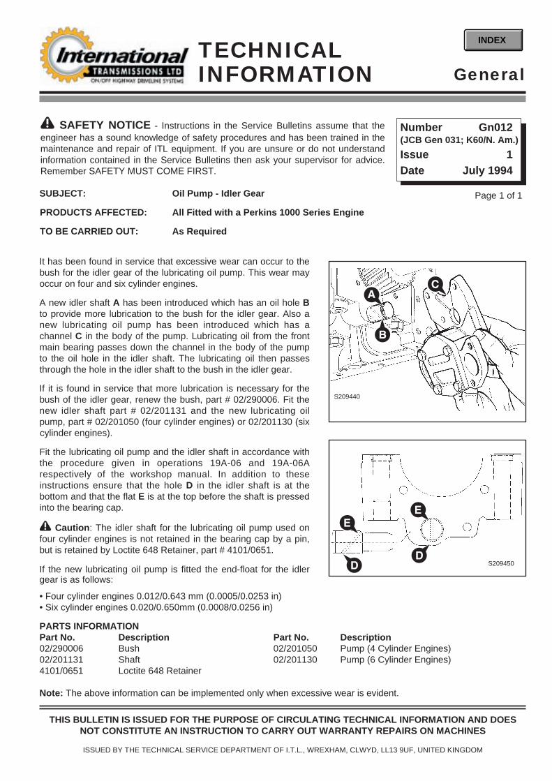
It has been found in service that excessive wear can occur to thebush for the idler gear of the lubricating oil pump. This wear mayoccur on four and six cylinder engines.
A new idler shaft A has been introduced which has an oil hole Bto provide more lubrication to the bush for the idler gear. Also anew lubricating oil pump has been introduced which has achannel C in the body of the pump. Lubricating oil from the frontmain bearing passes down the channel in the body of the pumpto the oil hole in the idler shaft. The lubricating oil then passesthrough the hole in the idler shaft to the bush in the idler gear.
If it is found in service that more lubrication is necessary for thebush of the idler gear, renew the bush, part # 02/290006. Fit thenew idler shaft part # 02/201131 and the new lubricating oilpump, part # 02/201050 (four cylinder engines) or 02/201130 (sixcylinder engines).
Fit the lubricating oil pump and the idler shaft in accordance withthe procedure given in operations 19A-06 and 19A-06Arespectively of the workshop manual. In addition to theseinstructions ensure that the hole D in the idler shaft is at thebottom and that the flat E is at the top before the shaft is pressedinto the bearing cap.
! Caution: The idler shaft for the lubricating oil pump used onfour cylinder engines is not retained in the bearing cap by a pin,but is retained by Loctite 648 Retainer, part # 4101/0651.
If the new lubricating oil pump is fitted the end-float for the idlergear is as follows:
• Four cylinder engines 0.012/0.643 mm (0.0005/0.0253 in)• Six cylinder engines 0.020/0.650mm (0.0008/0.0256 in)
PARTS INFORMATIONPart No. Description Part No. Description02/290006 Bush 02/201050 Pump (4 Cylinder Engines)02/201131 Shaft 02/201130 Pump (6 Cylinder Engines)4101/0651 Loctite 648 Retainer
Note: The above information can be implemented only when excessive wear is evident.
EE
D S209450
S209440
C
B
A
D
Page 1 of 1
! SAFETY NOTICE - Instructions in the Service Bulletins assume that theengineer has a sound knowledge of safety procedures and has been trained in themaintenance and repair of ITL equipment. If you are unsure or do not understandinformation contained in the Service Bulletins then ask your supervisor for advice.Remember SAFETY MUST COME FIRST.
Number Gn012(JCB Gen 031; K60/N. Am.)
Issue 1Date July 1994
GeneralTECHNICALINFORMATION
INDEX
THIS BULLETIN IS ISSUED FOR THE PURPOSE OF CIRCULATING TECHNICAL INFORMATION AND DOESNOT CONSTITUTE AN INSTRUCTION TO CARRY OUT WARRANTY REPAIRS ON MACHINES
ISSUED BY THE TECHNICAL SERVICE DEPARTMENT OF I.T.L., WREXHAM, CLWYD, LL13 9UF, UNITED KINGDOM

SUBJECT: Stake Nuts, Input and Output Flanges
PRODUCTS AFFECTED: All ITL Transmissions and Axles
TO BE CARRIED OUT: Information Only
SERVICE INFORMATION
1 AXLES Axle stake nuts A are now a combined nut and washer (instead of theseparate nut and washer arrangement). If this type of nut is used on anearlier type axle or 4WD flange, the old separate washer must bediscarded.
2 TRANSMISSIONSThe stake nut for the gearbox rear (2WD) output flange is nowmanufactured from 46 mm hexagonal bar. The existing 13/4 inchsocket can not be used on the 46 mm nuts. Make sure both types ofsocket are available in the event of site repair.
Note: The transmission rear (2WD) output flange is stillretained by the separate nut and washerarrangement, the washer should be replacedwith a new one if damaged or distorted.
Input & Output Flanges - The axle flanges and transmission outputflanges are now hardened (at the sealingarea). The hardened flanges prevent possibleoil leaks and loss of bearing pre-load byreducing the risk of fretting and subsequentloosening of the flanges.
In the event of a flange becoming loose or wearing, a new hardened type flange and new seal should be fitted. Applya small bead of Loctite 936 around the shaft spline. Full details for removing and replacing output flanges are given inthe relevant Workshop Manual.
PARTS INFORMATIONPart No. Description Qty Comments826/01482 Combine Stake Nut/Washer A/R M22826/01483 Combine Stake Nut/Washer A/R M24826/01551 Stake Nut A/R 46 mm - Gearbox
A
S224080
Note: The illustration shows atypical axle arrangement.
Page 1 of 1
! SAFETY NOTICE - Instructions in the Service Bulletins assume that theengineer has a sound knowledge of safety procedures and has been trained in themaintenance and repair of ITL equipment. If you are unsure or do not understandinformation contained in the Service Bulletins then ask your supervisor for advice.Remember SAFETY MUST COME FIRST.
Number Gn013(JCB Gen 035; F47/N. Am.)
Issue 1Date Feb. 1995
GeneralTECHNICALINFORMATION
INDEX
THIS BULLETIN IS ISSUED FOR THE PURPOSE OF CIRCULATING TECHNICAL INFORMATION AND DOESNOT CONSTITUTE AN INSTRUCTION TO CARRY OUT WARRANTY REPAIRS ON MACHINES
ISSUED BY THE TECHNICAL SERVICE DEPARTMENT OF I.T.L., WREXHAM, CLWYD, LL13 9UF, UNITED KINGDOM

SUBJECT: Fuel Injection Pump - Seal Failure
PRODUCTS AFFECTED: Perkins 1000 Series Engines
TO BE CARRIED OUT: By Perkins Dealers
SERVICE INFORMATION:The possibility exists that the shaft seal of the fuel injection pump has been damaged during the assembly process.The seal must be replaced with a new one otherwise serious damage to the engine could occur. Replacement of theseal is a specialised task and must only be done by the C.A.V. engineer; therefore please note the following:
1 The OEM Distributor must contact the local C.A.V. agent and quote reference number D137.
2 The OEM Dealer and the C.A.V. agent then arrange with the machine owner a suitable time to complete the repairprocedures (repair time 3.0 hours).
3 On arrival at the machine, the OEM engineer will remove the injection pump (see SERVICE PROCEDURES), oncethe pump has been removed it is given to the C.A.V. agent who will then replace the shaft seal.
4 The injection pump (complete with new seal) must then be refitted to the machine by the OEM engineer.
SERVICE PROCEDURES
Fuel Injection Pump Removal
Special Tools Required: Gear Puller - part number PD155CAdaptors - part number PD155B/5Spanner - part number PD199
1 Park the machine on firm level ground, engage the parking brake and set the transmission to neutral.
2 Raise the loader arms or the boom if necessary to access engine and fit safety strut.
3 Switch off the the engine and remove the starter key. Disconnect the battery.
....continued
Note: Existing workshop special tools - these itemsare not reclaimable on this FSI
Page 1 of 2
! SAFETY NOTICE - Instructions in the Service Bulletins assume that theengineer has a sound knowledge of safety procedures and has been trained in themaintenance and repair of ITL equipment. If you are unsure or do not understandinformation contained in the Service Bulletins then ask your supervisor for advice.Remember SAFETY MUST COME FIRST.
Number Gn014(JCB Gen 041; K68/N. Am.)
Issue 1Date August 1995
GeneralTECHNICALINFORMATION
INDEX
THIS BULLETIN IS ISSUED FOR THE PURPOSE OF CIRCULATING TECHNICAL INFORMATION AND DOESNOT CONSTITUTE AN INSTRUCTION TO CARRY OUT WARRANTY REPAIRS ON MACHINES
ISSUED BY THE TECHNICAL SERVICE DEPARTMENT OF I.T.L., WREXHAM, CLWYD, LL13 9UF, UNITED KINGDOM

SERVICE PROCEDURES (continued)
4 Remove the injection pump:
4.1 Remove all the pipes, cables and electricalconnections from the pump.
4.2 Remove the gear cover from the cover of the timingcase. Remove the gear nut and spring washer.
4.3 Rotate the crankshaft to ensure that the keyway inthe drive gear of the fuel pump is at or near to thetop.
4.4 Remove the setscrew and the nut of the supportbracket below the fuel pump. Release the flangenuts A of the fuel pump (see note). If access to theflange nuts is restricted, use tool PD199.
Note: Leave one flange nut loose on the end of the thread,this will prevent the pump from falling when the gear isremoved (step 4.5).
4.5 Loosen the drive gear of the fuel injection pumpwith the puller PD155C and adaptors PD155B/5, asshown at B (items 1 and 2).
4.6 Remove the fuel pump; ensure that the key doesnot fall from the drive shaft.
Fuel Injection Pump Replacement
1 Rotate the drive shaft of the fuel injection pump to align the key with the keyway in the drive gear. Ensure that thekey is correctly fitted and fit the fuel pump to the gear.
2 Align the mark on the flange of the fuel pump with the mark on the rear face of the timing case, shown at C. Fit theflange nuts A and the setscrew and the nut of the support bracket. Ensure that force is not applied to the fuel pumpwhen the support bracket is fitted.
3 Fit the spring washer and the nut to the drive shaft of the fuel pump and tighten the nut to 80 Nm (59 Ibf ft) 8,2 kgfm. Fit the gear cover to the cover of the timing case together with a new joint.
4 Fit all the pipes, cables and electrical connections. Reconnect the battery.
5 Eliminate air from the fuel system. Operate the engine and check for leakage. With the engine at the normaltemperature of operation, check that the idle speed is correct.
SERVICE PARTS:Part No. Description Qty Comments02/200976 Gasket 1 Injection Pump to Timing Case02/200029 Gasket 1 Injection Pump Gear Cover
Page 2 of 2 Gn014 Issue 1
B
C
A
S235030
S235040

SUBJECT: Engine Lubrication System - Relief Valve Housing
PRODUCTS AFFECTED: All Fitted with Perkins 1000 Series Engines
TO BE CARRIED OUT: By Perkins Dealers
SERVICE INFORMATION:The possibility exists that engine relief valve housing Amay fail. The relief valve controls the engine lubricatingsystem oil pressure, therefore a failure of the housingcould result in the loss of engine oil pressure and causesubsequent damage to the engine.
Investigation has shown that the relief valve housing hasbeen machined incorrectly and remedial procedures havealready been implemented to ensure all relief valvehousings are now machined to the correct specification.
Check the relief valve housing as described in SERVICEPROCEDURES.
SERVICE PROCEDURE:Note: The following procedures apply to a typical machine,the method for gaining access to the engine oil relief valvemay differ slightly.
1 Park the machine on firm level ground, engage theparking brake and set the transmission to neutral.Lower the attachments to the ground and stop theengine.
2 Place a clean suitable size container underneath theengine oil drain plug (located in the sump).
3 Remove the sump drain plug and its ‘O’ ring. Drainthe engine oil into the container.
4 Remove the engine oil dipstick and the dipstick tube.
ENGLISH
SPECIAL INSTRUCTIONSRefer to Perkins dealers for warranty information and repairs.
ISSUED BY THE TECHNICAL SERVICE DEPARTMENT OF I.T.L., WREXHAM, CLWYD, LL13 9UF, UNITED KINGDOM
S225960
A
ED
3766K0212
3766K0211 BC
Page 1 of 2
! SAFETY NOTICE - Instructions in the Service Bulletins assume that theengineer has a sound knowledge of safety procedures and has been trained in themaintenance and repair of ITL equipment. If you are unsure or do not understandinformation contained in the Service Bulletins then ask your supervisor for advice.Remember SAFETY MUST COME FIRST.
Number Gn015(JCB Gen 038; F66/N. Am.)
Issue 1Date Feb. 1996
GeneralTECHNICALINFORMATION
INDEX
Page 2 of 2 Gn015 Issue 1
SERVICE PROCEDURE (continued):5 Provide a support for the sump and remove the sump retaining bolts. Lower the sump and remove the sealing
gasket.
6 Inspect the relief valve housing:6.1 Look at the side of the relief valve housing A for the manufacturer’s number.6.2 If the number has a ‘1’ below it as shown at B, then the housing is made to the correct specification,
move to step 9.6.3 If the number has a ‘2’ below it as shown at C, then the housing is made to the wrong specification
and must be replaced with a new one, move to step 7.
Important note: Relief valves obtained from service parts stock with a number ‘2’ are manufactured to the correctspecification.
7 Remove the relief valve housing retaining bolt D, and then remove the relief valve housing A.
8 Fit a new replacement relief valve housing, torque tighten the retaining bolt to 22 Nm (16 lbf ft). Make sure thatthe ‘O’ ring at each end of tube E are in good condition and securely in place before tightening the retainingbolt.
9 Refit the engine sump together with a new gasket. Tighten the sump retaining bolts to 22 Nm (16 lbf ft). Fit thesump drain plug together with a new ‘O’ ring, torque tighten the plug to 34 Nm (25 lbf ft). Refit the dipstick anddipstick tube.
10 Using the engine oil drained at step 3 refill the engine sump, make sure that the engine oil reaches the ‘MAX’mark on the dipstick, top up as required.
PARTS REQUIREDPart No. Description Qty Comment02/200102 Relief Valve Assy 1 Turbo Engine02/200106 Relief Valve Assy 1 Naturally Aspirated Engine02/102069 Engine Sump Gasket 1 Cast Iron Sump02/200875 Engine Sump Gasket 1 Alloy Sump02/200198 Drain Plug ‘O’ ring 1 available only in units of 50 - part number 02/200198A

SERVICE INFORMATION
A new method of retaining the parkbrake cable to the lever and the caliper has been introduced. In place of theexisting clevis pin arrangement, new type shouldered bolts (items A and B) are used. The shouldered bolts aredirectly interchangeable with the clevis pin arrangement. When required, the shouldered bolts can be fitted asdescribed in SERVICE PROCEDURES.
SERVICE PROCEDURES
1 Park the machine on firm level ground, engage the parking brake and set the transmission to neutral. Lower theequipment to the ground and stop the engine.
2 Remove the parkbrake lever gaiter (item C).
3 Remove the clevis that holds the cable to the lever (item D), and in its place fit a new shouldered bolt (item A),washers (items E and F) and retaining nut (item G).
4 Remove the clevis that holds the cable to the caliper (item H), and in its place fit a new shouldered bolt (item B),washer (item F) and retaining nut (item G).
5 Check that the parkbrake fully engages (do a parkbrake test - refer to Operator Handbook). If necessary adjust theparkbrake as required.
6 Refit the parkbrake lever gaiter.
PARTS INFORMATION
Item No. Part No. Description Qty CommentsA 826/01596 Shouldered Bolt 1 Parkbrake cable to parkbrake leverB 826/01597 Shouldered Bolt 1 Parkbrake cable to caliperE 1420/0007Z 8 mm Flat Washer 2F 1420/0006Z 6 mm Flat Washer 2G 1370/0103Z 6 mm Nut 2
SUBJECT: Parkbrake Clevis Pin Improvements
PRODUCTS AFFECTED: Transmissions with Clysdale Type Park Brake
TO BE CARRIED OUT: Information Only
Page 1 of 2
! SAFETY NOTICE - Instructions in the Service Bulletins assume that theengineer has a sound knowledge of safety procedures and has been trained in themaintenance and repair of ITL equipment. If you are unsure or do not understandinformation contained in the Service Bulletins then ask your supervisor for advice.Remember SAFETY MUST COME FIRST.
Number Gn016(JCB 2/156; D19/N. Am.)
Issue 1Date Feb. 1996
GeneralTECHNICALINFORMATION
INDEX
THIS BULLETIN IS ISSUED FOR THE PURPOSE OF CIRCULATING TECHNICAL INFORMATION AND DOESNOT CONSTITUTE AN INSTRUCTION TO CARRY OUT WARRANTY REPAIRS ON MACHINES
ISSUED BY THE TECHNICAL SERVICE DEPARTMENT OF I.T.L., WREXHAM, CLWYD, LL13 9UF, UNITED KINGDOM

Page 2 of 2 Gn016 Issue 1
A
B
C
D
EE
F
G
H
F
G
SUBJECT Starter Motors
PRODUCTS AFFECTED All Perkins engines
SERVICE INFORMATION
A new specification of starter motor having a larger and stronger inertia clutch has been introduced in two forms foreither left hand or right hand mounting.
The engine serial cut-in numbers are:Right hand mounting on four cylinder engines: U 746654 B Left hand mounting on four cylinder engines: U 747324 BSix cylinder engines: U 620352 B.
The two new part numbers are fully interchangeable with the earlier starter motors as detailed below. For specificmachine applications, refer to the parts information.
Note that all starter motors failing within the warranty period should be repaired by the nearest Magnetti Marellidistributor. See T.I. Gn018 for list of Magneti Marelli distributors.
Contact Perkins or Perkins Dealer for further information.
Parts Required
Part No Description 714/29300 Starter motor, left hand mounting (supersedes 714/09100)714/29500 Starter motor, right hand mounting (supersedes 714/14300)
Page 1 of 1
! SAFETY NOTICE - Instructions in the Service Bulletins assume that theengineer has a sound knowledge of safety procedures and has been trained in themaintenance and repair of ITL equipment. If you are unsure or do not understandinformation contained in the Service Bulletins then ask your supervisor for advice.Remember SAFETY MUST COME FIRST.
Number Gn017(JCB Gen 045)
Issue 1Date March 1996
GeneralTECHNICALINFORMATION
INDEX
THIS BULLETIN IS ISSUED FOR THE PURPOSE OF CIRCULATING TECHNICAL INFORMATION AND DOESNOT CONSTITUTE AN INSTRUCTION TO CARRY OUT WARRANTY REPAIRS ON MACHINES
ISSUED BY THE TECHNICAL SERVICE DEPARTMENT OF I.T.L., WREXHAM, CLWYD, LL13 9UF, UNITED KINGDOM

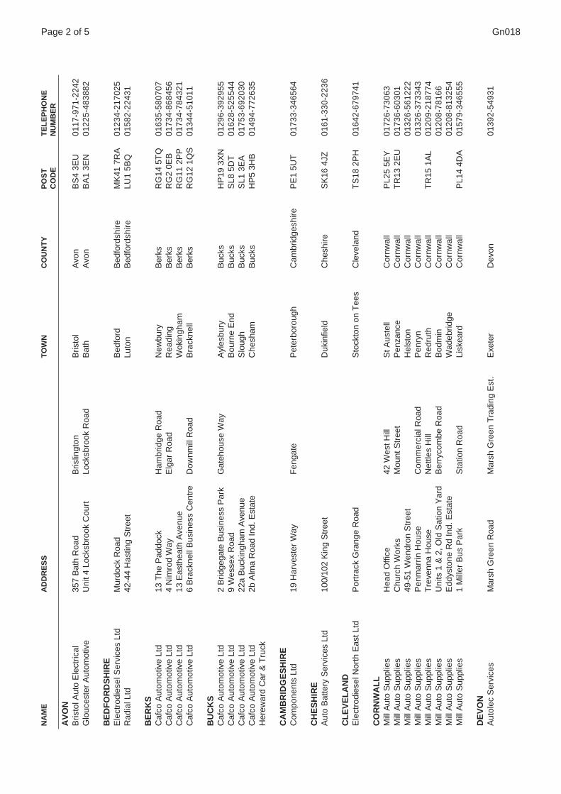
SUBJECT: Magneti Marelli Service/Warranty Support
PRODUCTS AFFECTED: All Fitted with Magneti Marelli Alternators and/or Starter Motors
From 1st January 1996, Service Warranty Support for Magnetti Marelli electrical equipment fitted on Perkins Engineswill be provided by Magnetti Marelli Distributors.
The addresses of the Magneti Marelli European main headquarters are listed below. The remaining pages identifydistributors in your country, so for instance, the translated JCB French version of this bulletin will only list the Frenchdistributor network, the German the German network, and so on. If there is no local Magneti Marelli agent, thestarter/alternator can either be repaired by a local electrical agent and the repair invoice submitted with a Warrantyclaim to a Perkins Dealer, or if required, a new unit can be supplied by a Perkins Dealer.
Page 1 of 5
MAGNETI MARELLI SERVICE HEADQUARTERS
U.K. - Magneti Marelli AftermarketShaftsmoor LaneHall GreenBirminghamB28 8SW
Tel: 0121-6258788Fax: 0121-6258625
ITALY - Magneti MarelliViale Aldo Borletti 61/6320011 CorbettaMilanoItalia
Tel: 00-39-0297200602Fax: 00-39-0297200500
FRANCE - Magneti Marelli France19 Rue Lavoisier92000 NanterreFrance
Tel: 00-33-147297000Fax: 00-33-147297274
GERMANY - Magneti Marelli KVWannenackerstrasse 7174078 HeilbronnGermany
Tel: 00-49-71312910Fax: 00-49- 7131176928
SPAIN - Magneti Marelli IbericaAvda de Roma 80-8208015 BarcelonaSpain
Tel: 00-34-32263176Fax: 00-34-32262109
Note: For JCB Language versions, only the front page is issue raised. When filing, replace the front sheet only.
! SAFETY NOTICE - Instructions in the Service Bulletins assume that theengineer has a sound knowledge of safety procedures and has been trained in themaintenance and repair of ITL equipment. If you are unsure or do not understandinformation contained in the Service Bulletins then ask your supervisor for advice.Remember SAFETY MUST COME FIRST.
Number Gn018(JCB MI 461/H, 431/E)
Issue 2Date Feb. 1999
GeneralTECHNICALINFORMATION
INDEX
THIS BULLETIN IS ISSUED FOR THE PURPOSE OF CIRCULATING TECHNICAL INFORMATION AND DOESNOT CONSTITUTE AN INSTRUCTION TO CARRY OUT WARRANTY REPAIRS ON MACHINES
ISSUED BY THE TECHNICAL SERVICE DEPARTMENT OF I.T.L., WREXHAM, CLWYD, LL13 9UF, UNITED KINGDOM
Note: If difficulty is experienced in finding support oroverseas warranty cover, contact Perkins U.K. on:
Tel: (UK 44)(0) 1733 567474Fax: (0) 1733 582240
Gn018Page 2 of 5
AV
ON
Bris
tol A
uto
Ele
ctric
al35
7 B
ath
Roa
dB
rislin
gton
Bris
tol
Avo
nB
S4
3EU
0117
-971
-224
2G
louc
este
r A
utom
otiv
eU
nit 4
Loc
ksbr
ook
Cou
rtLo
cksb
rook
Roa
dB
ath
Avo
nB
A1
3EN
0122
5-48
3882
BE
DF
OR
DS
HIR
EE
lect
rodi
esel
Ser
vice
s Lt
dM
urdo
ck R
oad
Bed
ford
Bed
ford
shire
MK
41 7
RA
0123
4-21
7025
Rad
ial L
td42
-44
Has
ting
Str
eet
Luto
nB
edfo
rdsh
ireLU
1 5B
Q01
582-
2243
1
BE
RK
SC
afco
Aut
omot
ive
Ltd
13 T
he P
addo
ckH
ambr
idge
Roa
dN
ewbu
ryB
erks
RG
14 5
TQ
0163
5-58
0707
Caf
co A
utom
otiv
e Lt
d4
Nim
rod
Way
Elg
ar R
oad
Rea
ding
Ber
ksR
G2
0EB
0173
4-86
8456
Caf
co A
utom
otiv
e Lt
d13
Eas
thea
th A
venu
eW
okin
gham
Ber
ksR
G11
2P
P01
734-
7843
21C
afco
Aut
omot
ive
Ltd
6 B
rack
nell
Bus
ines
s C
entr
eD
ownm
ill R
oad
Bra
ckne
llB
erks
RG
12 1
QS
0134
4-51
011
BU
CK
SC
afco
Aut
omot
ive
Ltd
2 B
ridge
gate
Bus
ines
s P
ark
Gat
ehou
se W
ayA
yles
bury
Buc
ksH
P19
3X
N01
296-
3929
55C
afco
Aut
omot
ive
Ltd
9 W
esse
x R
oad
Bou
rne
End
Buc
ksS
L8 5
DT
0162
8-52
5544
Caf
co A
utom
otiv
e Lt
d22
a B
ucki
ngha
m A
venu
eS
loug
hB
ucks
SL1
3E
A01
753-
6920
30C
afco
Aut
omot
ive
Ltd
2b A
lma
Roa
d In
d. E
stat
eC
hesh
amB
ucks
HP
5 3H
B01
494-
7726
35H
erew
ard
Car
& T
ruck
CA
MB
RID
GE
SH
IRE
Com
pone
nts
Ltd
19 H
arve
ster
Way
Fen
gate
Pet
erbo
roug
hC
ambr
idge
shire
PE
1 5U
T01
733-
3465
64
CH
ES
HIR
EA
uto
Bat
tery
Ser
vice
s Lt
d10
0/10
2 K
ing
Str
eet
Duk
infie
ldC
hesh
ireS
K16
4JZ
0161
-330
-223
6
CL
EV
EL
AN
DE
lect
rodi
esel
Nor
th E
ast L
tdP
ortr
ack
Gra
nge
Roa
dS
tock
ton
on T
ees
Cle
vela
ndT
S18
2P
H01
642-
6797
41
CO
RN
WA
LL
Mill
Aut
o S
uppl
ies
Hea
d O
ffice
42 W
est H
illS
t Aus
tell
Cor
nwal
lP
L25
5EY
0172
6-73
063
Mill
Aut
o S
uppl
ies
Chu
rch
Wor
ksM
ount
Str
eet
Pen
zanc
eC
ornw
all
TR
13 2
EU
0173
6-60
301
Mill
Aut
o S
uppl
ies
49-5
1 W
endr
on S
tree
tH
elst
onC
ornw
all
0132
6-56
1222
Mill
Aut
o S
uppl
ies
Pen
mar
rin H
ouse
Com
mer
cial
Roa
dP
enry
nC
ornw
all
0132
6-37
3343
Mill
Aut
o S
uppl
ies
Tre
venn
a H
ouse
Net
tles
Hill
Red
ruth
Cor
nwal
lT
R15
1A
L01
209-
2187
74M
ill A
uto
Sup
plie
sU
nits
1 &
2, O
ld S
atio
n Y
ard
Ber
ryco
mbe
Roa
dB
odm
inC
ornw
all
0120
8-78
166
Mill
Aut
o S
uppl
ies
Edd
ysto
ne R
d In
d. E
stat
eW
adeb
ridge
Cor
nwal
l01
208-
8132
54M
ill A
uto
Sup
plie
s1
Mill
er B
us P
ark
Sta
tion
Roa
dLi
skea
rdC
ornw
all
PL1
4 4D
A01
579-
3465
55
DE
VO
NA
utol
ec S
ervi
ces
Mar
sh G
reen
Roa
dM
arsh
Gre
en T
radi
ng E
st.
Exe
ter
Dev
on01
392-
5493
1
NA
ME
AD
DR
ES
ST
OW
NC
OU
NT
YP
OS
T
TE
LE
PH
ON
EC
OD
EN
UM
BE
R

Gn018Page 3 of 5
ES
SE
XG
P A
uto
119
Vic
toria
Roa
dR
omfo
rdE
ssex
RM
1 2L
X01
708-
7229
13M
otex
Exp
ress
Aut
o F
acto
rs14
Oba
n C
ourt
Hur
rican
e W
ayW
ickf
ord
Ess
exS
S11
8Y
B01
268-
5615
62
GL
OU
C E
ST
ER
Cen
tral
Mot
or F
acto
rs9-
13 H
igh
Str
eet
Lydn
eyG
louc
este
rG
L15
4DP
0159
4-84
5011
Cen
tral
Mot
or F
acto
rsN
ew R
oad
Par
kend
Lynd
eyG
louc
este
rG
L15
4JA
0159
4-56
3499
Glo
uces
ter
Aut
omot
ive
53 S
t. C
athe
rine
Str
eet
Glo
uces
ter
GL1
2B
S01
452-
3029
89G
louc
este
r A
utom
otiv
eU
nit 5
Low
er M
ill S
tree
tC
helte
nham
Glo
uces
ter
GL5
1 8J
N01
242-
5844
94G
louc
este
r A
utom
otiv
e R
iver
side
Wor
ksS
ever
n R
oad
Glo
uces
ter
GL1
2LE
0145
2-41
5555
HA
MP
SH
IRE
A.R
.E. L
tdA
lder
shot
Tru
ck S
pare
s16
Con
naug
ht R
oad
Ald
ersh
otH
amps
hire
GU
12 4
RN
0125
2-34
3228
A.R
.E. L
tdE
aste
rn R
oad
Ald
ersh
otH
amps
hire
GU
12 4
TD
0125
2-33
1448
A.R
.E. L
tdU
nit 1
Am
ey In
d. E
st.
Fre
nchm
ans
Roa
dP
eter
sfie
ldH
amps
hire
GU
32 3
AN
0173
0-26
8431
HE
RT
SR
adia
l Ltd
103
Long
sprin
gW
atfo
rdH
erts
WD
2 5P
O01
923-
2323
11R
adia
l Ltd
7 R
ailw
ay P
lace
Her
tford
Her
tsS
G13
7B
S01
992-
5814
93
IRE
LA
ND
Edm
unds
Wal
ker
JFK
Indu
stria
l Est
ate
Naa
s R
oad
Dub
ln 1
2Ir
elan
d00
-353
-1-4
5028
66E
dmun
ds W
alke
rC
olle
ge C
omm
erci
al P
ark
Den
nehy
s C
ross
Cor
kIr
elan
d00
-353
-21-
3446
88E
dmun
ds W
alke
r23
Nic
hola
s S
tree
tLi
mer
ick
Irel
and
00-3
53-6
1-41
9200
KE
NT
Caf
co A
utom
otiv
e Lt
d43
Sitt
ingb
ourn
e In
d. P
ark
Cro
wn
Qua
y La
neS
ittin
gbou
rne
Ken
tM
E10
3JG
0179
5-47
5321
LA
NC
AS
HIR
EA
uto
Bat
tery
Ser
vice
s Lt
dS
choo
l Lan
eR
ochd
ale
Lanc
ashi
reO
L16
1QR
0170
6-52
2522
Aut
o B
atte
ry S
ervi
ces
Ltd
Elli
ot H
ouse
Gre
enac
res
Roa
dO
ldha
mLa
ncas
hire
OL4
1H
B01
61-6
27-5
638
PF
Jon
es (
Die
sel S
ervi
ce)
Ltd
Nut
tall
Str
eet
Man
ches
ter
Lanc
ashi
reM
16 9
JA01
61-8
72-4
755
Rib
bles
dale
Dis
trib
utio
nC
ocke
r R
oad,
Bam
ber
Brid
geW
alto
n S
umm
it In
d E
st.
Pre
ston
Lanc
ashi
reP
R5
8AL
0177
2-62
9639
Leyl
and
Aut
o E
lec.
& D
iese
l Ltd
Uni
t 220
, Bam
ber
Brid
geW
alto
n S
umm
it In
d. E
st.
Pre
ston
Lanc
ashi
reP
R5
5AL
LIN
CS
Her
ewar
d C
ar &
Tru
ckB
row
nlow
Str
eet
Sta
mfo
rdLi
ncs
PE
9 2E
L01
780-
4812
34
LO
ND
ON
Mot
or T
rade
Ser
vice
s24
6/25
0 C
aven
dish
Roa
dB
alha
mLo
ndon
SW
12 0
BY
0181
-673
-555
5R
adia
l Ltd
Hill
way
Hig
hgat
eLo
ndon
N6
6QE
0181
-341
-055
3
MID
GL
AM
OR
GA
NA
utop
arts
Sou
th W
ales
Yny
sang
hara
d R
oad
Pon
typr
idd
Mid
Gla
mor
gan
CF
37 4
DA
0144
3-40
5726
NA
ME
AD
DR
ES
ST
OW
NC
OU
NT
YP
OS
T
TE
LE
PH
ON
EC
OD
EN
UM
BE
R

Gn018Page 4 of 5
MID
DL
ES
EX
Caf
co A
utom
otiv
e Lt
d96
Oxf
ord
Roa
dD
enha
mU
xbrid
geM
iddl
esex
UB
8 1L
V01
895-
2564
51
NO
RF
OL
KP
anks
Aut
o E
lect
rical
15 H
igha
m S
tree
tN
orw
ich
Nor
folk
NR
2 4T
E01
603-
6299
67
NO
RT
H Y
OR
KS
HIR
EA
ndre
w P
age
Ltd
Uni
t 25
Ray
lor
Cen
tre
Jam
es S
tree
tY
ork
Nor
th Y
orks
hire
YO
1 3D
P01
904-
4144
66A
ndre
w P
age
Ltd
Uni
t 6 T
hirs
k In
d. P
ark
Yor
k R
oad
Thi
rsk
Nor
th Y
orks
hire
YO
7 3T
A01
845-
5266
88S
.A.S
. Ltd
Uni
t 17
Pro
vinc
ial W
orks
The
Ave
nue
Har
roga
teN
orth
Yor
kshi
reH
G1
4QE
0142
3-88
9021
S.A
.S. L
tdW
estg
ate
Otle
yN
orth
Yor
kshi
reLS
21 3
AT
0194
3-46
7514
NO
TT
SM
idla
nd M
agne
toT
rent
Wor
ksC
anel
Str
eet
Not
tingh
amN
otts
NG
1 7H
L01
15-9
5522
33
OX
FO
RD
SH
IRE
Caf
co A
utom
otiv
e Lt
d29
b M
ilton
Par
kA
bing
don
Oxo
nO
X14
4R
T01
235-
8348
88C
afco
Aut
omot
ive
Ltd
59 M
urdo
ck R
oad
Bic
este
rO
xon
OX
6 7P
P01
869-
2446
12
SC
OT
LA
ND
D &
A F
acto
rs L
td2
Wes
t Hen
ders
ons
Wyn
dD
unde
eS
cotla
ndD
D1
5BT
0138
2-22
8202
D &
A F
acto
rs L
td42
Can
mor
e S
tree
tF
orfa
rS
cotla
nd01
307-
4649
14D
& A
Fac
tors
Ltd
13 B
altic
Str
eet
Mon
tros
eS
cotla
nd01
674-
6762
60D
& A
Fac
tors
Ltd
Uni
t 7 w
hite
fria
rsP
erth
Sco
tland
0173
8-63
6409
Eur
opea
n V
ehic
le E
quip
men
t13
Sco
tland
Str
eet
Gla
sgow
Sco
tland
G5
9PU
0141
-429
-270
4S
tanl
ey R
Har
ris L
td24
/40
Sea
war
d S
tree
tG
lasg
owS
cotla
ndG
41 1
HL
0141
-429
-314
1
SO
UT
H Y
OR
KS
HIR
EA
ndre
w P
age
Ltd
Uni
t 4 S
ilver
Cou
rtIn
terc
ity W
ayB
ram
ley
Sou
th Y
orks
hire
L13
4LY
0113
-236
-212
2S
utto
n A
uto
Fac
tors
New
cros
s S
tree
tS
utto
n in
Ash
field
Sou
th Y
orks
hire
0162
3-44
1331
ST
AF
FS
Car
Bar
Com
pone
nts
Ltd
Ket
tlebr
ook
Roa
dT
amw
orth
Sta
ffsB
77 1
AG
0182
7-60
111
Car
Bar
Com
pone
nts
Ltd
1 H
orni
nglo
w S
tree
tB
urto
n-on
-Tre
ntS
taffs
DE
14 1
NG
0128
3-53
4066
Mid
wes
t Mot
or F
acto
rsB
row
nhill
s B
usin
ess
Par
kLi
nden
Roa
dB
row
nhill
sS
taffs
WS
8 7B
W01
543-
3751
56P
otte
ries
Die
sel
Mas
on S
tree
tF
ento
nS
toke
on
Tre
ntS
taffs
ST
4 3N
E01
782-
7445
56
SU
RR
EY
A.R
.E. L
td28
5 W
orpl
esdo
n R
oad
Gui
ldfo
rdS
urre
yG
U2
6XN
0148
3-23
3003
A.R
.E. L
tdU
nit 1
Gol
dsw
orth
Ind.
Est
.G
oldw
orth
Roa
dW
okin
g S
urre
yG
U21
1LY
0148
3-72
2424
A.R
.E. L
tdH
are
Lane
Gol
dalm
ing
Sur
rey
GU
7 3E
G01
483-
4285
85A
.R.E
. Ltd
Uni
t 1 W
eydo
wn
Roa
dH
alsm
ere
Sur
rey
GU
27 1
DW
0142
8-65
4061
A.R
.E. L
td1-
3 E
ast S
tree
tF
arnh
amS
urre
yG
U9
7RX
0125
2-73
7654
A.R
.E. L
tdG
uild
ford
Tru
ck S
pare
s13
9 W
orpl
esdo
n R
oad
Gui
ldfo
rdS
urre
yG
U2
6XA
0148
3-57
3311
NA
ME
AD
DR
ES
ST
OW
NC
OU
NT
YP
OS
T
TE
LE
PH
ON
EC
OD
EN
UM
BE
R

Gn018Page 5 of 5
SU
RR
EY
A.R
.E. L
td28
2 W
alto
n R
oad
Eas
t Mol
esey
Sur
rey
KT
8 0H
U01
81-9
41-7
955
A.R
.E. L
tdU
nit 1
Dow
nsid
eG
uild
ford
Roa
dC
hert
sey
Sur
rey
KT
16 9
BQ
0193
2-57
0820
A.R
.E. L
td78
Hol
met
horp
e A
venu
eH
olm
etho
rpe
Ind.
Est
.R
edhi
llS
urre
yR
H1
2NL
0173
7-76
7000
A.R
.E. L
tdW
alto
n M
otor
Fac
tors
151-
153
Her
sham
Roa
dH
ersh
amS
urre
yK
T12
5N
R01
932-
2312
98
TY
NE
AN
D W
EA
RA
ndre
w P
age
Ltd
Uni
t 15
Bro
ugh
Par
kF
ossw
ayN
ewca
stle
-upo
n-T
yne
Tyn
e an
d W
ear
NE
6 2Y
F01
91-2
24-2
345
Tyn
esid
e A
uto
Ele
ctric
al L
tdS
t Law
renc
e R
oad
New
cast
le-u
pon-
Tyn
eT
yne
and
Wea
rN
E6
1AQ
0191
-265
-442
6
WE
ST
MID
LA
ND
SM
idw
est M
otor
Fac
tors
Uni
ts 1
0/11
Eru
ria W
ayB
arto
n P
ark
Ind.
Est
ate
Bils
ton
Wes
t Mid
land
sW
V14
7A
H01
902-
3535
15M
idw
est M
otor
Fac
tors
Wal
sall
Roa
dW
illen
hall
Wes
t Mid
land
sW
V13
2E
D01
902-
6330
05M
idw
est M
otor
Fac
tors
Uni
ts 2
, 3 &
6B
rand
on W
ay In
d. E
stat
eW
est B
rom
wic
hW
est M
idla
nds
B70
9P
W01
21-5
25-4
775
WE
ST
YO
RK
SH
IRE
And
rew
Pag
e Lt
dA
pson
Hou
se53
/59
Mab
gate
Leed
sW
est Y
orks
hire
LS9
7DY
0113
-200
-101
0A
ndre
w P
age
Ltd
Gra
ntle
y W
ayS
tanl
ey R
oad
Wak
efie
ldW
est Y
orks
hire
WF
1 4P
Y01
924-
3657
27A
ndre
w P
age
Ltd
Uni
t 5H
all L
ane
Bra
dfor
dW
est Y
orks
hire
BD
4 7D
G01
274-
7231
56A
ndre
w P
age
Ltd
Uni
ts 2
9-30
Bec
k R
oad
Rin
gway
Ind.
Est
ate
Hud
ders
field
Wes
t Yor
kshi
reH
D1
5DG
0148
4-42
0077
And
rew
Pag
e Lt
dU
nits
15/
17 A
shle
y In
d. E
st.
Elm
field
Roa
dM
orle
yW
est Y
orks
hire
LS27
0E
L01
13-2
52-6
600
WIL
TS
Mel
ksha
m M
otor
Spa
res
Ltd
16 C
hurc
h S
tree
tM
elks
ham
Wilt
sS
N12
6LS
0122
5-79
0123
WIN
CE
ST
ER
H.A
.E. L
tdW
ykeh
am In
dust
rial E
stat
eE
asto
n La
neW
inna
llW
ince
ster
SO
23 7
RX
0196
2-84
1010
WO
RC
ES
TE
RM
obile
Ele
ctric
(W
orce
ster
) Lt
dG
rego
rys
Mill
Str
eet
Wor
cest
erW
orce
ster
shire
WR
3 8B
S01
905-
2528
4
SC
AN
DIN
AV
IAN
orw
ay -
Jah
re M
otor
A/S
Bry
nsve
ien
2-4
0602
Osl
o 6
Fin
lan
d -
Ato
y O
Y1
Laut
tasa
aren
ti 54
0200
Hel
ensk
iD
enm
ark
- D
ybbr
oe A
/ST
omsa
gerv
ey 8
-10
0823
0 A
abyh
oj (
Aar
hus)
NA
ME
AD
DR
ES
ST
OW
NC
OU
NT
YP
OS
T
TE
LE
PH
ON
EC
OD
EN
UM
BE
R

SERVICE DEPARTMENT - COMPUTER DIAGNOSTIC EQUIPMENT
Electronic Control Units (ECU) have been introduced to control the functions of Transmissions.
Service Marketing is becoming increasingly important in generating distributor revenue. Introduction of ECU and EMSunits incorporating Service Indicators represents a major opportunity for distributors to ensure they obtain all routineservice work.
To support transmissions fitted with these systems, Distributor Service Personnel need to have the appropriateComputer Diagnostic equipment. All new ITL electronic systems will use the PSION Workabout hand held computerfor this purpose.
This bulletin describes the requirements for and technical specification of these computerised diagnostic tools.
1 PSION WORKABOUT
This low cost, rugged, hand held computer is now the ITL and JCB Group Diagnostic Tool. It is widely used inservice industries for in-field use.
All new ITL and JCB products with electronic systems requiring support from Service personnel will use softwarerunning on the PSION.
Electronic units requiring the PSION workabout will be as follows:-
Transmission ECUFitted to: PS700 four and five speed transmissions
Function: Control of powershift gearbox.
Use of PSION: Fault finding of ECU inputs and outputs.
The technical details of the PSION Workabout are:
Specification PSION Workabout PSION Part No. ITL/JCB part No.RS 232 and TTL Serial Interfaces 1800 0006-11 892/00924
Docking Holster One required per depot for 1801 0003-01 892/00925transferring software from PCto PSION Workabout
PsiWin Link and Software To transfer JCB software from 1601 0039-10 892/00926PC to PSION Workabout - one per depot
ITL SoftwareThis will be provided on the Parts CD ROM and will be transferred from a desktop computer via PsiWinsoftware to the PSION Workabout. A Psion disc is also available, JCB part No. 892/00963.
Cable links to machineConnecting cable for connecting the PSION Workabout to any ITL machine is part no. 892/00952, availablefrom JCB Service
A service kit comprising the above items is available, JCB part No. 892/00962
Page 1 of 3
! SAFETY NOTICE - Instructions in the Service Bulletins assume that theengineer has a sound knowledge of safety procedures and has been trained in themaintenance and repair of ITL equipment. If you are unsure or do not understandinformation contained in the Service Bulletins then ask your supervisor for advice.Remember SAFETY MUST COME FIRST.
Number Gn019(JCB M.I. 525/HA)
Issue 2Date Dec. 1998
GeneralTECHNICALINFORMATION
INDEX
ISSUED BY THE TECHNICAL SERVICE DEPARTMENT OF I.T.L., WREXHAM, CLWYD, LL13 9UF, UNITED KINGDOM

AvailabilityA list of PSION agents worldwide is attached.
PSION SupportTechnical Support for the PSION Workabout can be obtained from Psion Corporate Support, telephone:
(44) 1713174122.
Technical details of the Notebook PC are:
Specification:Preferably a ruggedised portable computer having:Pentium processor16 Meg memory or greater.1 Gb hard drive or greater.Internal CD ROM drive (4 speed or greater)
Operating System:Windows 3.11 or Windows 95
ITL Software:Will be provided on the Parts CD ROM
Cable links to machine:ITL part numbers will be advised in workshop manuals.
Availability:Any reputable computer supplier, JCB Service or ITL direct.
The facts about Workabout
Processor: 16-bit NEC V30H (80C86 compatible), multi-tasking, windowing environment.MS-DOS compatible file formats.
Memory: 256k -1 MByte RAM, 2 Solid State Disk drives for additional 16Mbytes
LCD Screen: 39 characters x 12 lines (240x100 pixels)Black and grey scale Backlight.
Keyboard: 57 key alphanumeric
Power Supply: 2 AA batteries, Rechargeable battery pack(optional) Lithium backup batteryExternal power via mains adaptor or Docking Station.
Integral applications: OPL language, Database,Spreadsheet and Calculator
Optional interfaces: Barcode wand and RS-232;TTL and RS-232 (for scanners)
Accessories: Elasticated strap
Operating Conditions: -20 to +60 Celsius,Humidity 90% maxnon-condensing
Drop resistance: One metre onto concrete
Weatherproofing: Standard model splashproof,optional on expansion interfaces
Dimensions: 180mm x 90mm x 35mm;325g (including batteries)
2 of 3 Gn019 - Issue 2

3 of 3 Gn019 - Issue 2P
SIO
N D
ISTR
IBU
TOR
Cou
ntry
Add
ress
Tele
phon
e N
umbe
rFa
x N
umbe
rE
-mai
lA
SK
INT
ER
NA
TIO
NA
L S
.A.R
.L.
ALG
ER
IA94
RN
133
, 423
80 S
OU
IDA
NIA
, W.T
IPA
SA
(213
) 27
9113
0(2
13)
2791
130
PS
IAR
AR
GE
NT
INA
AV
EN
IDA
DE
MA
YO
963
, 3R
D F
LOO
R, B
UE
NO
S A
IRE
S10
84(5
41)
345
2351
(541
) 34
5 36
05ps
iar@
satli
nk.c
omP
SIT
EC
H P
TY
AU
ST
RA
LIA
RM
B 3
585,
VA
LLE
Y R
OA
D, K
AN
GY
AN
GY
, NE
W S
OU
TH
WA
LES
225
8(6
1) 4
362
2014
(61)
436
2 20
14H
AY
WA
RD
CO
MP
UT
ER
-PE
RIP
HE
RIE
AU
ST
RIA
PO
ST
FA
CH
79,
A-5
071
WA
LS 4
05(4
3) 6
62 8
587
0(4
3) 6
62 8
587
80m
schi
nwal
d@ha
ywar
d.co
.at
CO
MP
UT
ER
WO
RLD
BA
HR
AIN
273
EX
HIB
ITIO
N A
VE
NU
E, H
OO
RA
PO
BO
X 2
6178
, MA
NA
MA
(973
) 29
3 49
3(9
73)
292
253
SH
AR
AN
EE
LT
DB
AN
GLA
DE
SH
B-1
72 L
AN
E-2
3, N
EW
D.O
.H.S
., D
HA
KA
120
6(8
80)
2885
219
(880
) 28
81 4
70M
ICR
OC
ON
NE
CT
ION
DIS
TR
IBU
TIO
NB
ELG
IUM
KO
RT
E W
INK
LES
TR
AA
T 1
5, B
-200
0 A
NT
WE
RP
EN
(32)
323
2 34
68(3
2) 3
226
1749
KP
F C
ON
SE
RV
E C
OB
RU
NE
ID
AR
US
SA
LAN
O 1
17 B
AN
GU
NA
N K
UM
BA
NG
PA
SA
NG
JALA
N G
AD
ON
G 3
180,
BA
ND
ER
SE
RI B
EG
AW
AN
(673
) 24
4810
1(6
73)
2 22
0988
psf@
brun
et.b
nIM
ICC
AM
BO
DIA
2 B
LVD
NO
RO
DO
M, P
HN
OM
PE
NH
, CA
MB
OD
IA(8
55)
23 3
62 3
92(8
55)
23 7
21 7
56cr
aigm
@un
i.fi
SY
SC
AN
INT
ER
NA
TIO
NA
L IN
C.
CA
NA
DA
2775
SH
ER
BR
OO
KE
EA
ST
, MO
NT
RE
AL,
QU
EB
EC
, H2K
1B
9(5
14)
521
0482
(514
) 52
1 09
49R
AD
IO-H
OLL
AN
D C
AR
IBB
EA
N N
.V.
CA
RIB
BE
AN
AT
HD
LLID
GE
RO
AD
106
, PO
BO
X 1
102,
ST
.MA
AR
TE
NS
(599
) 52
5 41
4(5
99)
522
589
mer
kus@
ibm
.net
BIN
AR
IA S
AC
HIL
EC
OM
PA
NIA
135
7, P
ISO
7, S
AN
TIA
GO
(562
) 69
6 21
33(5
62)
696
9368
PO
INT
X S
.R.O
.C
ZE
CH
RE
P.
TR
UH
LAR
SK
A 3
, 110
00 P
RA
GU
E 1
(42)
2 2
31 9
395
(42)
2 2
481
0821
poin
tx@
logi
n.cz
MO
BI D
AT
A A
/SD
EN
MA
RK
FU
GLE
BA
KK
EV
EJ
88-
90, D
K-2
000
FR
ED
RIK
ES
BU
RG
(45)
38
33 5
5 01
(45)
38
33 5
5 85
PR
OT
RA
DE
EG
YP
T11
SH
EH
AB
ST
RE
ET
, M
OH
AN
DE
SS
EE
N, C
AIR
O(2
0) 2
354
8184
7(2
0) 2
360
7638
OY
AN
GLO
-NO
RD
IC A
BF
INLA
ND
HY
TT
IME
ST
AR
INT
IE 3
, 027
80 E
SP
OO
(358
) 9
8192
11(3
58)
9 81
1338
psio
n@an
glo.
fiP
SIO
N F
RA
NC
E
FR
AN
CE
78 R
UE
CH
AM
PIO
NN
ET
, F 7
5018
PA
RIS
(33)
1 5
3411
200
(33)
1 5
3411
201
PS
ION
GM
BH
G
ER
MA
NY
DA
IMLE
RS
TR
AS
SE
16,
D-6
1352
BA
D H
OM
BU
RG
(49)
617
2 66
30(4
9) 6
172
6631
00IN
T E
LEC
TR
ON
ICG
RE
EC
E72
SY
NG
RO
U A
VE
NU
E, G
R -
117
42,
AT
HE
NS
(30)
1 9
2330
13(3
0) 1
923
4273
int@
hol.g
rO
NF
LO IN
TE
RN
AT
ION
AL
LTD
HO
NG
KO
NG
SU
ITE
181
8 1
8/F
MIR
AM
AR
TO
WE
R 1
KIM
BE
RLE
Y R
D, T
SIM
SH
AT
SU
I, K
OW
LOO
N(8
52)
2314
555
0(8
52)
2377
326
1do
min
ic@
onflo
.com
.hk
PS
ION
MA
GY
AR
OR
SZ
AG
KF
TH
UN
GA
RY
SZ
T. G
ELL
ER
T T
ER
.3, 1
111
BU
DA
PE
ST
(36)
120
9 38
04(3
6) 1
209
3805
10
0324
.102
@co
mpu
serv
e.co
mP
T K
OM
TE
LIN
DO
HIT
EK
INT
IIN
DO
NE
SIA
W
ISM
A M
ULT
I BIN
LAN
G,
JL D
R S
OE
PO
MO
SH
NO
44,
JA
KA
TA
(6
2) 3
617
5624
8(6
2) 3
617
5628
4ko
mte
l@ib
m.n
etS
IS S
UR
VE
YIR
ELA
ND
UN
IT 6
A,
BA
LLY
MO
UN
T C
RO
SS
IND
US
TR
IAL
ES
, DU
BLI
N 1
2(3
53)
456
8650
(353
) 45
6 86
53he
m@
cix.
com
pulin
kV
IDE
O C
OM
PU
TE
RIT
ALY
VIA
AN
TO
NE
LLI 3
6,10
093
CO
LLE
GN
O(3
9) 1
1 40
3 48
28(3
9) 1
1 40
3 33
25P
SIO
N J
AP
AN
JAP
AN
NIS
HI S
HIN
JUK
U F
OR
ES
T B
LD.,
LB F
LOO
R N
ISH
I SH
INJU
KU
4-3
2-1S
HIN
JUK
U-K
U, T
OK
YO
(81)
3 3
378
5933
(81)
3 3
378
5943
AN
WA
R E
SS
A A
L S
ALE
H E
ST
AB
.K
UW
AIT
AL-
RA
BIE
BLD
G,S
ALM
IYA
, PO
BO
X 4
704,
SA
FA
T, 1
3048
(965
) 57
3 76
84(9
65)
571
6674
esal
eh@
kuw
ait.n
etC
OM
PU
TE
L S
.A.R
.L.
LEB
AN
ON
JUS
TIN
IAN
CE
NT
RE
, JU
ST
INIA
N S
T, S
AN
AY
EH
, PO
BO
X 1
13 6
413,
BE
(961
) 1
353
748
(961
) 1
602
193
CO
MP
@D
M.N
ET
.LB
ALC
HE
MY
TE
CH
NO
LOG
Y S
DN
BH
DM
ALA
YS
IAM
UI P
LAZ
A 3
RD
FLO
OR
, KU
ALA
LU
MP
AR
, 502
50(6
0) 3
248
3318
(60)
324
5 63
18B
DS
MA
LTA
CA
SA
LE
ON
E, P
IAZ
ZA
RO
BE
RT
SA
MU
T,
FLO
RIA
NN
A V
LT 1
4(3
56)
2392
00(3
56)
2486
93T
DT
ME
XIC
OP
AS
A F
LOR
EN
TIN
O 4
7, S
AN
TA
FE
, CP
01
260
(52)
5 3
97 8
290
(52)
5 3
61 3
755
PS
ION
NE
DE
RLA
ND
BV
NE
TH
ER
LAN
DS
AV
IO T
RA
DE
PA
RK
, ZA
ND
ST
EE
N 5
4, 2
132
MR
HO
OF
DD
OR
P(3
1) 2
0 44
6944
4(3
1) 2
0 44
6944
6P
OC
KE
T S
OLU
TIO
NS
NE
W Z
EA
LAN
D11
RU
TH
ER
FO
RD
ST
RE
ET
, PO
BO
X 4
4070
, LO
WE
R H
UT
WE
LLIN
GT
ON
(64)
456
6 78
08(6
4) 4
569
6452
psol
002@
ibm
.net
DE
BIS
NIG
ER
IA11
0 O
BA
FE
MI A
WO
LOW
O W
AY
, IK
EJA
, LA
GO
S S
TA
TE
(234
) 14
9702
26/7
(234
) 14
9702
28/9
UC
OM
NO
RW
AY
(47)
322
0330
0(4
7) 3
2203
459
OH
I ELE
CT
RO
NIC
S &
TR
AD
ING
CO
LLC
OM
AN
PO
BO
X 8
89,
MU
SC
AT
113
,SU
LTA
NA
TE
OF
OM
AN
(968
) 95
9 08
5(9
68)
603
467
CH
AR
LES
FR
EW
EN
P
AR
AG
UA
YV
ALI
AN
A S
AL,
PA
ET
ON
ALC
OR
ON
ELM
ON
ELO
S 1
35, C
AS
I AV
SA
N B
LAS
(55)
455
22 1
451
(55)
455
22 1
451
BO
RR
OM
EO
PH
ILLI
PP
INE
SG
& A
BLD
G, 2
303
PA
SO
NG
TA
MO
BLD
G(6
3) 2
893
772
2(6
3) 2
816
410
7bt
him
ktg@
glob
e.co
m.p
hC
IE C
EN
TR
UM
INF
OR
MA
TY
KI E
NE
RG
ET
YP
OLA
ND
UL
MY
SIA
2, S
KR
- P
OC
ZT
143
, 00-
950
WA
RS
ZA
WA
1(4
8) 2
2 62
5 33
97(4
8) 2
2 69
3 13
57ci
esm
@el
mo.
nask
.waw
.pl
CO
MP
3 L
DA
P
OR
TU
GA
LR
UA
AU
GU
ST
O G
ILL
30 A
/B, 1
100
LIS
BO
N(3
51)
1 79
5 18
72(3
51)
1 79
5 19
28P
SI-
RU
SS
IA
RU
SS
IA
INT
ER
NA
TIO
NA
L U
NIV
ER
SIT
Y O
F E
NG
6 LE
NIN
SK
Y P
RO
SP
EK
T, G
SP
, MO
SC
OW
117
933
(7)
095
236
6531
(7
) 09
5 23
6 97
6ke
nmor
e@ro
diti.
co.u
kN
AB
IL A
LI S
IND
I TR
AD
ING
ES
TA
BLI
SS
AU
DI A
RA
BIA
P
O B
OX
295
1, J
ED
DA
H 2
1461
(966
) 2
6829
454
(966
) 2
6828
801
SY
ST
EC
HS
ING
AP
OR
E25
KA
LLA
NG
AV
EN
UE
#02.
01/0
3, K
ALL
AN
G B
AS
IN IN
DU
ST
RIA
L E
ST
AT
3394
16(6
5) 2
99 2
933
x236
(65)
299
968
8sy
stec
h@si
ngne
t.com
.sg
PS
ION
ET
DIS
TR
IBU
TO
RS
CC
SO
UT
H A
FR
ICA
PO
BO
X 3
6233
, GLO
SD
ER
RY
, CA
PE
TO
WN
770
0 (2
7) 2
1 68
3 11
92(2
7) 2
1 68
3 11
96P
AR
ES
A
SP
AIN
RA
MLA
CA
TA
LUN
YA
35,
PR
AL,
080
07 B
AR
CE
LON
A(3
4) 3
451
6505
(34)
3 4
8725
16K
ING
SLA
KE
EN
G S
YS
TE
MS
S
RI L
AN
KA
12 T
ICK
ELL
RO
AD
, CO
LOM
BO
8, S
RI L
AN
KA
(9
4) 1
695
395
(94)
1 6
9587
4dh
arm
a@sr
i.lan
ka.n
etS
VE
NS
KA
IND
US
TR
IELE
KT
RO
NIC
AB
SW
ED
EN
F O
PE
TE
RS
ON
S G
AT
A, 4
21 3
1 V
AS
TR
A F
RO
LUN
DA
, SW
ED
EN
(46)
31
709
1605
(46)
31
47 8
520
sten
.soh
le@
indu
strie
lekt
roni
k.se
EX
CO
M A
GS
WIT
ZE
RLA
ND
MO
OS
AC
HE
R S
TR
AS
SE
6,
CH
882
0 W
AD
EN
SW
IL(4
1) 1
782
211
1(4
1) 1
781
136
1in
fos@
exco
m.c
hO
.AB
OU
KH
ALI
L T
RA
DIN
G C
OS
YR
IAP
O B
OX
105
4, D
AM
AS
CU
S(9
63)
11 2
3174
60
(963
) 11
442
1966
JEB
SE
N &
JE
SS
EN
TH
AIL
AN
D17
79/1
NE
W P
ET
CH
BU
RI R
D, B
AN
GK
OK
103
20, T
HA
ILA
ND
(66)
2 2
53 1
290
(66)
2 2
53 1
705
INS
TIT
UT
MA
SS
ME
DIA
TU
NIS
IAG
ALA
XIE
200
0, R
UE
D’L
AK
BLO
C A
7 E
ME
ET
AG
E,1
002
TU
NIS
(216
) 1
793
939
(216
) 1
794
949
ALP
HA
55
CO
. L.L
.C.
UA
E1s
t Flo
or B
IN K
HE
DIA
CE
NT
ER
, AL
GA
RH
OU
D, D
UB
AI
(971
) 4
8222
67(9
71)
4 82
2265
alph
a55@
emira
tes.
net.a
eP
SIO
N U
K P
LCU
K1
RE
D P
LAC
E,
MA
YF
AIR
, LO
ND
ON
W1Y
3R
E
0171
317
410
0P
SIO
N U
K S
ER
VIC
E C
EN
TR
EU
K6
DE
RB
Y R
OA
D, M
ET
RO
PO
LIT
AN
CE
NT
RE
, GR
EE
NF
OR
D, M
IDD
’X, U
B6
8UJ
0181
566
616
201
81 5
66 6
268
PS
ION
INC
.,U
SA
15
0 B
AK
ER
AV
EN
UE
, C
ON
CO
RD
, M
A 0
1742
(001
) 50
8 37
1 03
10(0
01)
508
371
9611
AL
AH
MA
R G
RO
UP
Y
EM
EN
AL
SA
LAM
ES
T. ,
YE
ME
N(9
67)
2715
06(9
67)
2739
90

ENGINE WORKSHOP MANUALS
Perkins New 1000 Series (“Darwin”)
With the introduction of the ‘New 1000’ Series range of engines, Perkins produced a new Workshop Manual which isavailable under publication number 9806/2140.
Issue 3 of this publication is now available incorporating two additional engine models (AR and AS) which are formachines sold primarily in North America and Scandinavia. The new issue also incorporates various generalrevisions.
Any future orders for 9806/2140 will be supplied as issue 3.
French and German translations of issue 3 should be available by the end of May. Other languages will follow later.
Translated part numbers are: French: 9806/2141 German: 9806/2142Spanish: 9806/2143Italian: 9806/2144
Note: Replacement pages are not supplied for engine service manuals. To obtain the latest issue a new manual mustbe ordered.
Engine models now covered by the new manual will be: 4 Cylinder: Models AJ to AS
Page 1 of 1
! SAFETY NOTICE - Instructions in the Service Bulletins assume that theengineer has a sound knowledge of safety procedures and has been trained in themaintenance and repair of ITL equipment. If you are unsure or do not understandinformation contained in the Service Bulletins then ask your supervisor for advice.Remember SAFETY MUST COME FIRST.
Number Gn020(JCB M.I. 612/H, 548/E)
Issue 1Date April 1998
GeneralTECHNICALINFORMATION
INDEX
THIS BULLETIN IS ISSUED FOR THE PURPOSE OF CIRCULATING TECHNICAL INFORMATION AND DOESNOT CONSTITUTE AN INSTRUCTION TO CARRY OUT WARRANTY REPAIRS ON MACHINES
ISSUED BY THE TECHNICAL SERVICE DEPARTMENT OF I.T.L., WREXHAM, CLWYD, LL13 9UF, UNITED KINGDOM

SUBJECT Axle Propshafts
PRODUCTS AFFECTED All Machine Installations
SERVICE INFORMATIONOn installation of any machine it is important to ensure that the following points regarding propshaft lubrication andprotection are highlighted to the operator. Failure to do so may result in premature wear or consequential damage totransmission components.
1 Lubrication
Propshafts must be greased as follows:
a) Interval- Every 50 hours of operation- Daily if working in muddy conditions- Immediately after washing the machine
b) Ensure that all bearing caps are purged with grease
c) Only High Pressure Grease such as Mobil HP222should be used.
2 Washing
Do not direct high pressure water jets at universal joints.
3 Protection
When working in loose straw or grass it is important thatan undershield is fitted to the machine to prevent materialwrapping around the propshafts.
Failure to protect the propshafts adequately may result indamage to oil seals, propshafts and other transmissioncomponents.
Parts Information
Part No Description 4003/2017 JCB HP Grease (400 g cartridge) Available from JCB Service and Dealers
Page 1 of 1
! SAFETY NOTICE - Instructions in the Service Bulletins assume that theengineer has a sound knowledge of safety procedures and has been trained in themaintenance and repair of ITL equipment. If you are unsure or do not understandinformation contained in the Service Bulletins then ask your supervisor for advice.Remember SAFETY MUST COME FIRST.
Number Gn021(JCB 10/107)
Issue 1Date April 1998
GeneralTECHNICALINFORMATION
INDEX
THIS BULLETIN IS ISSUED FOR THE PURPOSE OF CIRCULATING TECHNICAL INFORMATION AND DOESNOT CONSTITUTE AN INSTRUCTION TO CARRY OUT WARRANTY REPAIRS ON MACHINES
ISSUED BY THE TECHNICAL SERVICE DEPARTMENT OF I.T.L., WREXHAM, CLWYD, LL13 9UF, UNITED KINGDOM
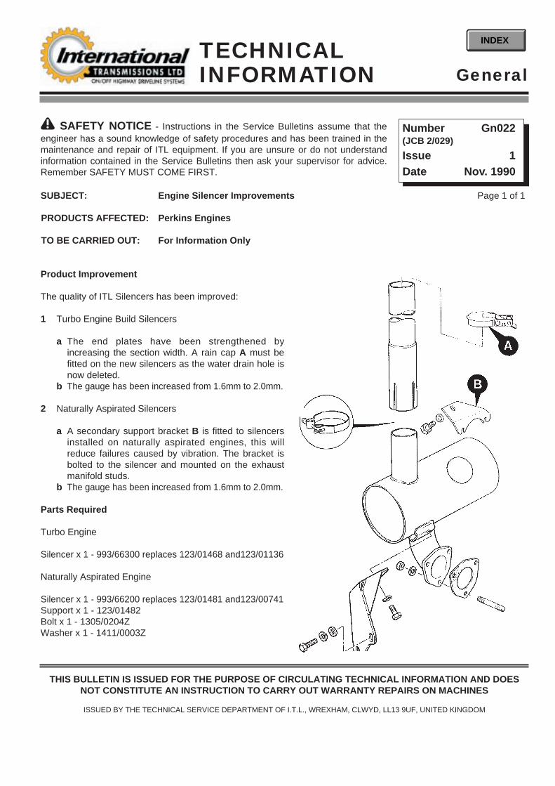
SUBJECT: Engine Silencer Improvements
PRODUCTS AFFECTED: Perkins Engines
TO BE CARRIED OUT: For Information Only
Product Improvement
The quality of ITL Silencers has been improved:
1 Turbo Engine Build Silencers
a The end plates have been strengthened byincreasing the section width. A rain cap A must befitted on the new silencers as the water drain hole isnow deleted.
b The gauge has been increased from 1.6mm to 2.0mm.
2 Naturally Aspirated Silencers
a A secondary support bracket B is fitted to silencersinstalled on naturally aspirated engines, this willreduce failures caused by vibration. The bracket isbolted to the silencer and mounted on the exhaustmanifold studs.
b The gauge has been increased from 1.6mm to 2.0mm.
Parts Required
Turbo Engine
Silencer x 1 - 993/66300 replaces 123/01468 and123/01136
Naturally Aspirated Engine
Silencer x 1 - 993/66200 replaces 123/01481 and123/00741 Support x 1 - 123/01482Bolt x 1 - 1305/0204ZWasher x 1 - 1411/0003Z
Page 1 of 1
! SAFETY NOTICE - Instructions in the Service Bulletins assume that theengineer has a sound knowledge of safety procedures and has been trained in themaintenance and repair of ITL equipment. If you are unsure or do not understandinformation contained in the Service Bulletins then ask your supervisor for advice.Remember SAFETY MUST COME FIRST.
Number Gn022(JCB 2/029)
Issue 1Date Nov. 1990
GeneralTECHNICALINFORMATION
INDEX
THIS BULLETIN IS ISSUED FOR THE PURPOSE OF CIRCULATING TECHNICAL INFORMATION AND DOESNOT CONSTITUTE AN INSTRUCTION TO CARRY OUT WARRANTY REPAIRS ON MACHINES
ISSUED BY THE TECHNICAL SERVICE DEPARTMENT OF I.T.L., WREXHAM, CLWYD, LL13 9UF, UNITED KINGDOM

SUBJECT: Change of position for the exhaust manifold alignment bushes
PRODUCTS AFFECTED: New Perkins 1000 Series Engines (Models AJ to AS and YG to YK)
TO BE CARRIED OUT: For information
SERVICE INFORMATION:
The information published in section 12 of the New Perkins1000 Series Workshop manual, 9806/2140 has changed. Newalignment bushes must be fitted in accordance with thisService Bulletin.
Note: Always use the engine identification number to ordernew parts, alignment bushes are not fitted to all engines.
The exhaust manifolds fitted to some four and six cylinderengines have large clearance holes for the setscrews. It isimportant that these manifolds are correctly fitted to thecylinder head.
Caution: Damage to the exhaust manifold can occur if it is notaligned and tightened correctly.
SERVICE PROCEDURE:
If the manifold is renewed, it is important that the twoalignment bushes (1), JCB part number 02/201783 are inposition. New alignment bushes are not necessary when theoriginal manifold is removed and fitted.
Tighten the exhaust manifold setscrews evenly and graduallyto 44 Nm (33 lbf ft, 4.5 kgf m) in the sequence shown). Use thesame sequence and torque tighten the setscrews again.
The front of the engine is shown by the arrow (2).
Refer to Perkins or a Perkins dealer for Perkins part numbers or further information.
Page 1 of 1
! SAFETY NOTICE - Instructions in the Service Bulletins assume that theengineer has a sound knowledge of safety procedures and has been trained in themaintenance and repair of ITL equipment. If you are unsure or do not understandinformation contained in the Service Bulletins then ask your supervisor for advice.Remember SAFETY MUST COME FIRST.
Number Gn023(JCB Gen 087, N.Am K91)
Issue 1Date Oct. 1998
GeneralTECHNICALINFORMATION
INDEX
THIS BULLETIN IS ISSUED FOR THE PURPOSE OF CIRCULATING TECHNICAL INFORMATION AND DOESNOT CONSTITUTE AN INSTRUCTION TO CARRY OUT WARRANTY REPAIRS ON MACHINES
ISSUED BY THE TECHNICAL SERVICE DEPARTMENT OF I.T.L., WREXHAM, CLWYD, LL13 9UF, UNITED KINGDOM
1
1
2

SUBJECT: Pin-timed Fuel Injection Pumps
PRODUCTS AFFECTED: All Perkins New 1000 Series Engines (Models AJ to AS & YG to YK)
TO BE CARRIED OUT: For Information Only
SERVICE INFORMATION:
The latest fuel injection pumps have a hub A which ismounted permanently onto the drive shaft.
The manufacturer fits the hub to the pump to ensure veryaccurate timing. Engines that have this arrangement,require a pin B (part no. 892/00956) to accurately time thepump in service.
Caution: Do not release the nut C from the fuel injectionpump. Illustration 2 shows the nut C in position when thefuel pump is fitted to the engine. The fuel pump hub isfitted to the shaft in the factory to ensure that the fuel pumpis in the correct position for timing. If the nut is removedand the hub moves, the hub will need to be accurately fittedto the pump by use of specialist equipment before thepump can be fitted to the engine.
Always refer to the relevant workshop manual(publication no. 9806/2140) for the correct procedurebefore you start to work on the engine.
To remove the fuel injection pump from the engine it is onlynecessary to remove the four setscrews D which securethe fuel pump gear to the hub. It is important to follow theinstructions in the workshop manual to ensure the enginetiming is correct.
Page 1 of 1
! SAFETY NOTICE - Instructions in the Service Bulletins assume that theengineer has a sound knowledge of safety procedures and has been trained in themaintenance and repair of ITL equipment. If you are unsure or do not understandinformation contained in the Service Bulletins then ask your supervisor for advice.Remember SAFETY MUST COME FIRST.
Number Gn024(JCB Gen 089; K94/N.Am)
Issue 1Date Jan. 1999
GeneralTECHNICALINFORMATION
INDEX
THIS BULLETIN IS ISSUED FOR THE PURPOSE OF CIRCULATING TECHNICAL INFORMATION AND DOESNOT CONSTITUTE AN INSTRUCTION TO CARRY OUT WARRANTY REPAIRS ON MACHINES
ISSUED BY THE TECHNICAL SERVICE DEPARTMENT OF I.T.L., WREXHAM, CLWYD, LL13 9UF, UNITED KINGDOM
B
CA
1
2
C
D

Warning! The engine oil may be hot. Allow the engineto cool down before the oil pipes are released.
Caution! Do not remove both of the oil pipes together.
2 Put a drip tray under the cooler and remove thelubricating oil pipes from the oil cooler. Do notremove both of the oil pipes together. Remove oneof the pipes, then fit the flanges A and nuts B ontothe studs again before the other pipe is removed.This will ensure that the element is fastened to thecover when the assembly is removed.
All Perkins 1000 Series Engines Models YA to YK
Introduction of an improved Oil Cooler with aPressed Steel Cover
An improved oil cooler with a pressed steel cover hasbeen introduced with effect from engine serial numberYB-------U647452C.
To Remove1 Drain the cooling system; refer to the relevant
service manual.
Page 1 of 3
! SAFETY NOTICE - Instructions in the Service Bulletins assume that theengineer has a sound knowledge of safety procedures and has been trained in themaintenance and repair of ITL equipment. If you are unsure or do not understandinformation contained in the Service Bulletins then ask your supervisor for advice.Remember SAFETY MUST COME FIRST.
Number Gn025(JCB Gen 090; K95/N.Am)
Issue 1Date January 1999
GeneralTECHNICALINFORMATION
INDEX
THIS BULLETIN IS ISSUED FOR THE PURPOSE OF CIRCULATING TECHNICAL INFORMATION AND DOESNOT CONSTITUTE AN INSTRUCTION TO CARRY OUT WARRANTY REPAIRS ON MACHINES
ISSUED BY THE TECHNICAL SERVICE DEPARTMENT OF I.T.L., WREXHAM, CLWYD, LL13 9UF, UNITED KINGDOM
A
B
C
D
E
F
GH
J
K
L
M
N
P

Page 2 of 3 Gn025 Issue 1
3 Discard the ‘O’ rings C.
4 Release the fasteners D from the cover of the oilcooler and remove the oil cooler assembly E.
5 Thoroughly clean the flange face of the cover andof the cylinder block.
Note: A liquid joint is used in the factory. This must beremoved and a new paper joint F, JCB part number02/201718, fitted in its place.
6 If an overhaul of the oil cooler is necessary, see ToDismantle and To Assemble on pages 2 and 3 ofthis bulletin.
To Fit1 If the four studs G have been removed from the
cylinder block flange and are to be fitted again,clean the threads in the cylinder block and on thestuds. Apply High Strength Retainer before thestuds are fitted to the cylinder block to preventleakage of the coolant.
2 Put a new paper joint into position on the studs; thejoint is fitted dry. Fit the oil cooler assembly E to thecylinder block. Gradually and evenly tighten thefasteners D to 22 Nm (16 lbf ft, 2.2 kgf m).
3 Clean the seats for the ‘O’ rings and renew the ‘O’rings C of the pipe connections.
Caution! Do not remove the flanges A and nuts B fromthe studs H before one of the oil pipes is fitted to thecover. This will ensure that the element is held inposition on the cover J while the oil pipes are fitted.
4 Fit the oil pipes to the cooler and tighten the nuts to22 Nm (16 lbf ft, 2.2 kgf m).
5 Fill the cooling system.
6 Operate the engine and check for oil or coolantleakage.
To Dismantle1 Remove the oil cooler from the cylinder block, refer
to page 1 of this bulletin.
2 Put the oil cooler assembly E on a clean worksurface. Release the four nuts B that retain theflanges for the lubricating oil pipes. The pipeflanges A are in two pieces.
3 Remove the cover K from the four studs L of the oilcooler element M.
A
B
C
D
E
F
GH
J
K
L
M
N
P

Page 3 of 3 GN025 Issue 1
4 Remove and discard the three-piece ‘O’ ring N fromthe element.
Warning! Do not allow compressed air to contact yourskin. If compressed air enters your skin, obtain medicalhelp immediately.
5 Clean the element and check for cracks. If asolution is used to clean the outside of the element,ensure that this does not enter the element. Checkthat there is nothing to restrict the flow of lubricatingoil through the element of the oil cooler. If the insideof the element needs to be cleaned, use a solventwhich is suitable for copper. Dry the element withlow pressure air and then flush it with clean enginelubricating oil.
To Assemble1 Clean the seats of the three-piece ‘O’ ring and
renew the ‘O’ rings N.
2 Clean the flange face P for the three-piece ‘O’ ringson the inside of the cover.
3 Fit the cover of the oil cooler to the element M.
4 Fit the two-piece flanges A onto the studs H.Tighten the nuts to retain the element when the oilcooler assembly is fitted to the engine.
5 Fit the oil cooler to the cylinder block, see page 2 ofthis bulletin.
A
B
C
D
E
F
GH
J
K
L
M
N
P

Perkins 4.236 or 1000 Series Engines
Introduction of a Wear Sleeve for the Front Oil Seal
The latest timing case fitted to 4.236 and 1000 Seriesengines, does not have a service position for the frontoil seal, as shown in section 15 of the relevantworkshop manual.
The change improves the efficiency of the oil seal inservice and was introduced from engine number:
L------U786357C for 4.236 engines.A------U802612C for 4 cylinder 1000 series.
Caution: If the lip of the oil seal has worn a groove inthe spigot A of the crankshaft pulley, oil will continue toleak after the new oil seal is fitted.
To renew a worn crankshaft pulley, for engines with thelatest timing case, a wear sleeve B part number02/202027 is fitted over the spigot.
Full instructions and a special tool to fit the wear sleeveare in each service kit.
The dimension to press the new oil seal into the timingcase, with or without a wear sleeve fitted, is 9.3 mm(0.366 in), from the front face of the timing case. Thespecial tool supplied in the kit can be used to set thecorrect depth.
It is not necessary to remove the flange C of the wearsleeve after it has been fitted.
A new front oil seal must be used when a wear sleeve isfitted.
Page 1 of 1
! SAFETY NOTICE - Instructions in the Service Bulletins assume that theengineer has a sound knowledge of safety procedures and has been trained in themaintenance and repair of ITL equipment. If you are unsure or do not understandinformation contained in the Service Bulletins then ask your supervisor for advice.Remember SAFETY MUST COME FIRST.
Number Gn026(JCB Gen 091; K96/N.Am)
Issue 1Date February 1999
GeneralTECHNICALINFORMATION
INDEX
THIS BULLETIN IS ISSUED FOR THE PURPOSE OF CIRCULATING TECHNICAL INFORMATION AND DOESNOT CONSTITUTE AN INSTRUCTION TO CARRY OUT WARRANTY REPAIRS ON MACHINES
ISSUED BY THE TECHNICAL SERVICE DEPARTMENT OF I.T.L., WREXHAM, CLWYD, LL13 9UF, UNITED KINGDOM
A
C
B

New Perkins 1000 Series Engines(Models AJ to AS & YG TO YK)
Washers for the Fuel Injection Pump Gear
Caution: Ensure that the washers are fitted before thescrews are tightened.
A washer, part number 02/101686, is fitted to each ofthe screws A with effect from the following engine serialnumbers:
A----U812611C for 4 cylinder enginesY----U660846C for 6 cylinder engines
Engines before the above numbers do not need to havethese washers fitted.
Page 1 of 1
! SAFETY NOTICE - Instructions in the Service Bulletins assume that theengineer has a sound knowledge of safety procedures and has been trained in themaintenance and repair of ITL equipment. If you are unsure or do not understandinformation contained in the Service Bulletins then ask your supervisor for advice.Remember SAFETY MUST COME FIRST.
Number Gn027(JCB Gen 092; K97/N.Am)
Issue 1Date February 1999
GeneralTECHNICALINFORMATION
INDEX
THIS BULLETIN IS ISSUED FOR THE PURPOSE OF CIRCULATING TECHNICAL INFORMATION AND DOESNOT CONSTITUTE AN INSTRUCTION TO CARRY OUT WARRANTY REPAIRS ON MACHINES
ISSUED BY THE TECHNICAL SERVICE DEPARTMENT OF I.T.L., WREXHAM, CLWYD, LL13 9UF, UNITED KINGDOM
A
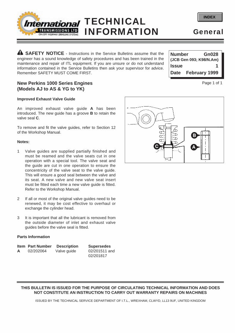
New Perkins 1000 Series Engines(Models AJ to AS & YG to YK)
Improved Exhaust Valve Guide
An improved exhaust valve guide A has beenintroduced. The new guide has a groove B to retain thevalve seal C.
To remove and fit the valve guides, refer to Section 12of the Workshop Manual.
Notes:
1 Valve guides are supplied partially finished andmust be reamed and the valve seats cut in oneoperation with a special tool. The valve seat andthe guide are cut in one operation to ensure theconcentricity of the valve seat to the valve guide.This will ensure a good seal between the valve andits seat. A new valve and new valve seat insertmust be fitted each time a new valve guide is fitted.Refer to the Workshop Manual.
2 If all or most of the original valve guides need to berenewed, it may be cost effective to overhaul orexchange the cylinder head.
3 It is important that all the lubricant is removed fromthe outside diameter of inlet and exhaust valveguides before the valve seal is fitted.
Parts Information
Item Part Number Description SupersedesA 02/202064 Valve guide 02/201511 and
02/201817
Page 1 of 1
! SAFETY NOTICE - Instructions in the Service Bulletins assume that theengineer has a sound knowledge of safety procedures and has been trained in themaintenance and repair of ITL equipment. If you are unsure or do not understandinformation contained in the Service Bulletins then ask your supervisor for advice.Remember SAFETY MUST COME FIRST.
Number Gn028(JCB Gen 093; K98/N.Am)
Issue 1Date February 1999
GeneralTECHNICALINFORMATION
INDEX
THIS BULLETIN IS ISSUED FOR THE PURPOSE OF CIRCULATING TECHNICAL INFORMATION AND DOESNOT CONSTITUTE AN INSTRUCTION TO CARRY OUT WARRANTY REPAIRS ON MACHINES
ISSUED BY THE TECHNICAL SERVICE DEPARTMENT OF I.T.L., WREXHAM, CLWYD, LL13 9UF, UNITED KINGDOM
A
B
C

SUBJECT: ITL Hydraulic Hose Fittings and O-rings
PRODUCTS AFFECTED: All ITL Products
TO BE CARRIED OUT: Information Only
SERVICE INFORMATION
ITL products use their own type of special BSP hydraulic hose fitting. This fitting combines the standard BSP typeconed connector with an O-ring seal X fitted in the face of the taper.
The O-ring is bonded to the fitting to ensure its security. However, if for any reason the O-ring becomes damaged orseparated from the fitting, it can be replaced.
It is very important to use the correct O-ring size for the fitting. Any deviation in O-ring size or specification (eg. O-ringtaken from a selection kit that appears to be the correct size and material) will cause joint integrity and leakingproblems.
The correct O-rings X required for the various sizes of hydraulic fitting are shown below:
Hydraulic Fitting O-ring O-ring Inner O-ring Section MaterialSize Part Number Diameter (mm) Diameter (mm) Type
1/4” BSP fitting 828/00237 6.5 (± 0.15) 1.0 (± 0.08) A3/8” BSP fitting 2301/0006 8.1 (± 0.15) 1.6 (± 0.08) A1/2” BSP fitting 2301/0010 12.1 (± 0.2) 1.6 (± 0.08) A5/8” BSP fitting 2301/0011 13.1 (± 0.2) 1.6 (± 0.08) A3/4” BSP fitting 2301/0015 17.1 (± 0.2) 1.6 (± 0.08) A1” BSP fitting 2301/0018 22.1 (± 0.25) 1.6 (± 0.08) A1 1/4” BSP fitting 2302/0907 29.1 (± 0.25) 1.6 (± 0.08) B1 1/2” BSP fitting 2302/0908 35.1 (± 0.3) 1.6 (± 0.08) B
Material Type:
A - Nitrile synthetic rubber suitable for use between -40° and +135° Celsius with a hardness value of 80 IRHD.B - Polyurethane material suitable for use between -40° and +130°Celsius with a Shore hardness value of 93A.
Ensure that only the above O-ring part numbers are used as replacements in ITL hydraulic hose fittings.
Page 1 of 2
! SAFETY NOTICE - Instructions in the Service Bulletins assume that theengineer has a sound knowledge of safety procedures and has been trained in themaintenance and repair of ITL equipment. If you are unsure or do not understandinformation contained in the Service Bulletins then ask your supervisor for advice.Remember SAFETY MUST COME FIRST.
Number Gn029(JCB Gen 096; E194/N. Am)
Issue 1Date March 1999
GeneralTECHNICALINFORMATION
INDEX
THIS BULLETIN IS ISSUED FOR THE PURPOSE OF CIRCULATING TECHNICAL INFORMATION AND DOESNOT CONSTITUTE AN INSTRUCTION TO CARRY OUT WARRANTY REPAIRS ON MACHINES
ISSUED BY THE TECHNICAL SERVICE DEPARTMENT OF I.T.L., WREXHAM, CLWYD, LL13 9UF, UNITED KINGDOM

Page 2 of 2 Gn029 Issue 1
WARRANTY INFORMATION
If submitting a warranty claim for rectification of a problem with a hydraulic fitting O-ring (eg. oil leak), ensure thecorrect O-ring part number is specified within the claim as the failed part. Incorrect O-ring part number claims will notbe accepted.
X

PERKINS LOW EMISSION DIESEL ENGINE - ITL PRODUCT IMPROVEMENTS
New Perkins Diesel Engine
• Improved exhaust emissions• Wastegated turbo charger• Improved injection pump• Increased peak torque• Improved cold starting
performance
Page 1 of 3
! SAFETY NOTICE - Instructions in the Service Bulletins assume that theengineer has a sound knowledge of safety procedures and has been trained in themaintenance and repair of ITL equipment. If you are unsure or do not understandinformation contained in the Service Bulletins then ask your supervisor for advice.Remember SAFETY MUST COME FIRST.
Number Gn030(JCB MI642/H)
Issue 1Date April 1999
GeneralTECHNICALINFORMATION
INDEX
THIS BULLETIN IS ISSUED FOR THE PURPOSE OF CIRCULATING TECHNICAL INFORMATION AND DOESNOT CONSTITUTE AN INSTRUCTION TO CARRY OUT WARRANTY REPAIRS ON MACHINES
ISSUED BY THE TECHNICAL SERVICE DEPARTMENT OF I.T.L., WREXHAM, CLWYD, LL13 9UF, UNITED KINGDOM
THIS BULLETIN CONTAINS INFORMATION WHICH SHOULD BE COVERED DURING CUSTOMER MACHINEINSTALLATION AND SHOULD BE COPIED TO ALL MACHINE INSTALLATION PERSONNEL.
Please ensure a copy of this bulletin is distributed to field based service engineers and make sure that a copy isposted on your technical information notice boards.

Page 2 of 3 Gn030 Issue 1
The Perkins low emission diesel engine has been introduced for all Powertrains with turbo-charged engines sold inthe EEC after 1st January 1999, and for all Powertrains with naturally aspirated engines sold in the EEC after 1st April1999. These dates apply to the engine build date and not the machine build date.
The engines comply with mandatory emission legislation and incorporate the following changes:
• Revised cylinder head• Four branch inlet and exhaust manifolds• Revised piston design with modified combustion chamber• Wastegated turbo charger• Improved fuel injection pump• Increased compression ratio
The previous 75 hp (56 kW) engine is now uprated to 80 hp (59 kW) and develops 290 Nm (214 lbf ft) peak torque.
The previous 106 hp (79 kW) engine is replaced by a 100 hp (74 kW) turbo charged engine which develops 402 Nm(296 lbf ft) peak torque.
Torque Comparison
The comparison shows the increased back-up torque at lower engine speed produced by the new low emissionengine. Peak torque is increased up to a possible 411 Nm (lbf ft) from 354 Nm (261 lbf ft) depending on air filter andexhaust silencer specification.
280
300
320
340
360
800 1000 1200 1400 1600 1800 2000 2200 2400 2600
Engine Speed (rev/min)
380
400
420 Torque(Nm)
1
2
1 102 hp Perkins new low emission engine:Max. torque 411 Nm (303 lbf ft) @ 1400 rev/min
2 106 hp engine:Max. torque 354 Nm (261 lbf ft) @ 1800 rev/min
1
2
1
2

Page 3 of 3 Gn030 Issue 1
1 Engine Specifications
Nat. Asp. Build Turbo Build
Horsepower: 80hp 102hpInjection pump type: DP203 DP203Governing: Mechanical MechanicalPump setting code: 2644G521/YG/1/2350 2644C705/BG/1/2350Static timing: Pre-set Pre-setIdle speed: 800 rpm 800 rpmMax. rated speed: 2200 rpm 2200 rpmMax. no-load speed: 2350 rpm 2350 rpmInjector codes: KW KNInjector setting pressure: 294 atm 294 atm
Note: Either 65A or 85A alternators may be fitted (refer to ITL Technical Sales).
2 Regulations
The new engines meet EEC Stage 1 emission regulations. Smoke emission is dramatically reduced and now meetsECE R24.03.
3 Servicing
Routine engine service intervals remain unchanged at initial 100 hour and 500 hour periods. Valve clearance must bechecked every 1000 hours. There is no change to the engine oil or fuel filter part numbers. Only use oil meeting orexceeding CF4/SG specification for the low emission engine. The fuel injector pump is significantly more sophisticatedand because the emissions are reduced by increasing the accuracy of the timing, alterations to the fuel pump are notpossible. Any alteration to the fuel pump settings will invalidate the emission certification.
4 Starting
Cold start performance has been improved. This is achieved via an additional temperature switch situated in the rearof the timing case which causes fuel injection timing to advance in cold conditions. In line with these cold startimprovements, the diameter of the battery leads has been increased.
5 Special Tool Requirement
All essential special tool requirements are incorporated into the relevant Perkins engine service manuals.
6 Technical Publications
With the introduction of the new low emission range of engines, a new engine workshop manual is available from tehorganisation using the following publication numbers:
English French German Spanish ItalianEngine Workshop Manual 9806/2140 9806/2141 9806/2142 9806/2143 9806/2144
7 Mandatory and Recommended Distributor Parts Lists
Contact Perkins Service for mandatory and recommended parts list requirements.
8 Training
Contact Perkins Service/Dealers.

SUBJECT: Hydraulic Ram Sealing Procedure
PRODUCTS AFFECTED: All Machines with ITL Rams
TO BE CARRIED OUT: Information Only
SERVICE INFORMATION:
In an effort to reduce the number of hydraulic leaks on ITL rams a revised procedure has been introduced for fittingseals to the ram end cap and piston head.
The introduction of the new procedure also introduces new tools which are detailed on sheet 3.
Service Manuals will be revised at the next convenient Replacement Page Set.
SERVICE PROCEDURE:
Page 1 of 3
! SAFETY NOTICE - Instructions in the Service Bulletins assume that theengineer has a sound knowledge of safety procedures and has been trained in themaintenance and repair of ITL equipment. If you are unsure or do not understandinformation contained in the Service Bulletins then ask your supervisor for advice.Remember SAFETY MUST COME FIRST.
Number Gn031(JCB Gen 105; E215/N.Am)
Issue 1Date Nov. 1999
GeneralTECHNICALINFORMATION
INDEX
THIS BULLETIN IS ISSUED FOR THE PURPOSE OF CIRCULATING TECHNICAL INFORMATION AND DOESNOT CONSTITUTE AN INSTRUCTION TO CARRY OUT WARRANTY REPAIRS ON MACHINES
ISSUED BY THE TECHNICAL SERVICE DEPARTMENT OF I.T.L., WREXHAM, CLWYD, LL13 9UF, UNITED KINGDOM
To fit new rod seal:
Use seal fitting tool (892/00334) to fit rod seals, the size(diameter) and position of pins A is determined by thediameter and radial width of the rod seal being fitted.
The pins are screwed into threaded holes in the toolbody, the spacing of the holes is designed to suit smallor large diameter rod seals.
1 Open the tool as shown at B and insert the new rodseal, the seal must be fitted behind the two frontpins but in front of the rear pin as shown.
B
C D
A
161750

Page 2 of 3 Gn031 Issue 1
Note: Later ram end caps and piston heads have metricthreads. The seals are also different, make sure thecorrect seals are fitted. On metric threaded rams makesure the seals are fitted the correct way round, asshown at P and Q.
2 Close the tool as shown at C. The seal must form areniform (kidney shape).
3 Before fitting the rod seals check the seal groovesare free of contamination and sharp edges,
4 Locate the seal in the end cap groove, shown at D,when the seal is in position, open the tool torelease the seal. Make sure the seal is correctlyinstalled in its groove and remove the tool.
5 Fit rod wiper seal P into seal groove. Make sure theseal is correctly installed as shown.
Note: Some rod wipers, ie power track rod, may use ametal encased seal which is pressed into the housing.Care must be taken to ensure the seal is square beforeit is pressed in.
Sleeve E must be used to protect the rod seals fromdamage when fitting end cap onto the piston rod. Thereare various sizes of sleeve, see Parts Information. Makesure the hexagon on the end cap is towards the eyeend of the rod.
Fit new piston head seals:
6 Use a blunt instrument (892/01027) shown at F,lever the inner seal G into the piston head sealgroove, do not let the seal twist. There areidentification marks on the outer diameter of theseal, make sure the marks are visible and the sealis free to rotate, if not remove the seal and refit
7 Fit outer seal H using the same procedure as step6. Check the external grooves are visible.
A187361
338470
E
F
G
Q
P
153212
338480
H

Page 3 of 3 Gn031 Issue 1
8 Ensure O ring is fitted into the internal seal grooveon the piston head. Screw the piston head onto thethread of the piston rod, refer to the relevantsection for torque figure and completion of ramassembly.
9 Fit the piston head retaining dowel, see ramdismantling and assembling relevant section.
10 Fit wear rings J and K. Rotate the wear rings sothat the piston retention dowel is covered by thewear ring, NOT as shown at L.
Fit the piston rod and head assembly into the cylinder:
11 Insert the piston/rod assembly into the cylinder.Align the rod and head assembly until parallel withthe cylinder then push the assembly into thecylinder.
12 Fit the end cap, refer to the relevant section fortorque figure and completion of ram assembly.
PARTS INFORMATION
Ram Seal Protection Sleeves
892/01016 For 25 mm Rod Diameter892/01017 For 30 mm Rod Diameter892/01018 For 40 mm Rod Diameter892/01019 For 50 mm Rod Diameter892/01020 For 50 mm Rod Diameter (slew ram)892/01021 For 60 mm Rod Diameter892/01022 For 60 mm Rod Diameter (slew ram)892/01023 For 65 mm Rod Diameter892/01024 For 70 mm Rod Diameter892/01025 For 75 mm Rod Diameter892/01026 For 80 mm Rod Diameter
S338410
892/01027 Piston Seal Assembly Tool
110mm
175mm
R 1.4mm
3o
R3mm
7mm
11o
10mm 20mm
5mm
338490
L
KJ
338500

SUBJECT: Oil Control Rings
PRODUCTS AFFECTED: 1000 series engine models AR & AS only
TO BE CARRIED OUT: For Information Only
SERVICE INFORMATION
A small taper has been added to the face of the oil control ring to reduce oil consumption during the early life of theengine. The ring is marked ‘TOP’ on the top face and a blue mark has been added to the left of the ring gap.
The oil control ring is a component of a ring kit (see part numbers listed below). The ring kit could be supplied witheither the earlier or the later oil control ring.
SERVICE PROCEDURE
When fitting the oil control ring, check if there is a blue mark at X.
If there is a blue mark at X, the ring must be fitted with the mark to theleft of the ring gap. The word ‘TOP’ will then be towards the top of thepiston.
If there is no blue mark, the ring can be fitted either way up.
Ring Kit Part Numbers
Standard 02/2018040.5 mm oversize 02/2017911.0 mm oversize 02/201793
Page 1 of 1
! SAFETY NOTICE - Instructions in the Service Bulletins assume that theengineer has a sound knowledge of safety procedures and has been trained in themaintenance and repair of ITL equipment. If you are unsure or do not understandinformation contained in the Service Bulletins then ask your supervisor for advice.Remember SAFETY MUST COME FIRST.
Number Gn032(JCB Gen 110; K110 N/Am)
Issue 1Date Jan. 2001
GeneralTECHNICALINFORMATION
INDEX
THIS BULLETIN IS ISSUED FOR THE PURPOSE OF CIRCULATING TECHNICAL INFORMATION AND DOESNOT CONSTITUTE AN INSTRUCTION TO CARRY OUT WARRANTY REPAIRS ON MACHINES
ISSUED BY THE TECHNICAL SERVICE DEPARTMENT OF I.T.L., WREXHAM, CLWYD, LL13 9UF, UNITED KINGDOM
X

SUBJECT: Plastic Thermostat Housings
PRODUCTS AFFECTED: All 1000 series engines
TO BE CARRIED OUT: For Information Only
SERVICE INFORMATION
Plastic thermostat housings, fitted to some engines, will be damaged if temperature senders or blanking plugs areovertightened.
SERVICE PROCEDURE
When fitting the items listed, ensure that the followingtorque settings are used:
Item Nm kgf m lbf ftA - Sender (aluminium) 16 12 12A - Sender (brass) 24 2.4 18B - 1/2 inch Plug (metal or plastic) 4 0.4 3B - 3/4 inch Plug (metal or plastic) 4 0.4 3
Note: The illustration shows a typical installation whichmay differ from some engines.
Page 1 of 1
! SAFETY NOTICE - Instructions in the Service Bulletins assume that theengineer has a sound knowledge of safety procedures and has been trained in themaintenance and repair of ITL equipment. If you are unsure or do not understandinformation contained in the Service Bulletins then ask your supervisor for advice.Remember SAFETY MUST COME FIRST.
Number Gn033(JCB Gen 112; K112 N.Am)
Issue 1Date Jan. 2001
GeneralTECHNICALINFORMATION
INDEX
THIS BULLETIN IS ISSUED FOR THE PURPOSE OF CIRCULATING TECHNICAL INFORMATION AND DOESNOT CONSTITUTE AN INSTRUCTION TO CARRY OUT WARRANTY REPAIRS ON MACHINES
ISSUED BY THE TECHNICAL SERVICE DEPARTMENT OF I.T.L., WREXHAM, CLWYD, LL13 9UF, UNITED KINGDOM
A
B

SUBJECT: Introduction of Improved Fuel Lift Pump
PRODUCTS AFFECTED: All Perkins Four Cylinder 1000 Series Engines
TO BE CARRIED OUT: Information only
SERVICE INFORMATION:
An improved fuel lift pump has been introduced for use on Perkins four-cylinder 1000 Series diesel engines. The newpump is a one piece assembly and cannot be dismantled. The new pump is interchangeable with the earlier pump.
The procedure to remove and fit the new pump has not changed. Remove and clean fuel inlet strainer 2 if thisprocedure is recommended in the relevant machine handbook or service manual.
Cleaning the Strainer
1 Allow the engine to cool. Remove the fuel filler cap to vent the system and reduce loss of fuel. Disconnect thefuel inlet pipe to the lift pump.
2 Unscrew the fuel filter A. Remove strainer 2 and O-ring 3.
3 Clean the strainer in clean diesel fluid and dry with low pressure compressed air. Renew the strainer and O-ringif damaged.
4 Fit the strainer into the fuel inlet connection. Fit the fuel filter A and tighten to20Nm (15 lbf ft). Fit the fuel inlet pipe carefully to prevent damage to thestrainer, and tighten the union nut.
IMPORTANT: The fuel strainer can be damaged and fuel flow can berestricted if the fuel pipe is inserted too far into the inlet connection. Thisshould be checked if a fuel restriction is suspected.
Make sure the olive on the fuel inlet pipe is in good condition and forms aneffective seal. Renew the olive or pipe if necessary to prevent air entering thefuel system.
5 Fit the tank cap and prime the fuel system. Start the engine and check forfuel leakage.
Page 1 of 2
!! SAFETY NOTICE - Instructions in the Service Bulletins assume that theengineer has a sound knowledge of safety procedures and has been trained in themaintenance and repair of ITL equipment. If you are unsure or do not understandinformation contained in the Service Bulletins then ask your supervisor for advice.Remember SAFETY MUST COME FIRST.
Number Gn034(JCB Gen 114; K109/N. Am)
Issue 1Date Feb. 2001
GGeenneerraallTECHNICALINFORMATION
INDEX
THIS BULLETIN IS ISSUED FOR THE PURPOSE OF CIRCULATING TECHNICAL INFORMATION AND DOESNOT CONSTITUTE AN INSTRUCTION TO CARRY OUT WARRANTY REPAIRS ON MACHINES
ISSUED BY THE TECHNICAL SERVICE DEPARTMENT OF I.T.L., WREXHAM, CLWYD, LL13 9UF, UNITED KINGDOM
1

Page 2 of 2 Gn 034 Issue 1
PARTS INFORMATION
Item Part No. Description1 17/913600 Fuel Lift Pump Kit (complete with Gasket)2 & 3 17/913601 Fuel Strainer & O-ring Kit4 02/201189 Gasket only
A
23
1
4
366610
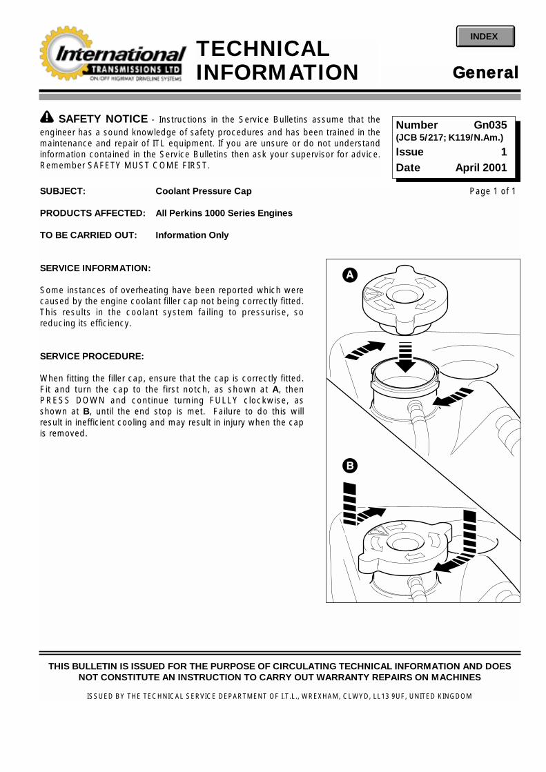
SUBJECT: Coolant Pressure Cap
PRODUCTS AFFECTED: All Perkins 1000 Series Engines
TO BE CARRIED OUT: Information Only
SERVICE INFORMATION:
Some instances of overheating have been reported which werecaused by the engine coolant filler cap not being correctly fitted.This results in the coolant system failing to pressurise, soreducing its efficiency.
SERVICE PROCEDURE:
When fitting the filler cap, ensure that the cap is correctly fitted.Fit and turn the cap to the first notch, as shown at A, thenPRESS DOWN and continue turning FULLY clockwise, asshown at B, until the end stop is met. Failure to do this willresult in inefficient cooling and may result in injury when the capis removed.
Page 1 of 1
!! SAFETY NOTICE - Instructions in the Service Bulletins assume that theengineer has a sound knowledge of safety procedures and has been trained in themaintenance and repair of ITL equipment. If you are unsure or do not understandinformation contained in the Service Bulletins then ask your supervisor for advice.Remember SAFETY MUST COME FIRST.
Number Gn035(JCB 5/217; K119/N.Am.)
Issue 1Date April 2001
GGeenneerraallTECHNICALINFORMATION
INDEX
THIS BULLETIN IS ISSUED FOR THE PURPOSE OF CIRCULATING TECHNICAL INFORMATION AND DOESNOT CONSTITUTE AN INSTRUCTION TO CARRY OUT WARRANTY REPAIRS ON MACHINES
ISSUED BY THE TECHNICAL SERVICE DEPARTMENT OF I.T.L., WREXHAM, CLWYD, LL13 9UF, UNITED KINGDOM
B
A

SUBJECT: Engine Oil Consumption
PRODUCTS AFFECTED: Perkins Low Emission Engines (AJ to AS and YG to YK)
TO BE CARRIED OUT: For Information Only
SERVICE INFORMATION:
Engine oil consumption can only be correctly measured as a percentage against fuel used under controlledconditions. If, after consideration of the observations below the oil consumption appears to exceed the expectedamount, carry out the Service Procedure as detailed.
Oil consumption does not normally exceed 4.5 litres (1.0 UK gal., 1.19 US gal) per 100 hours average machine use.
No test should be carried out on new engines prior to the bedding in period, minimum of 100 hours.
Engines should not be idled for long periods and should be worked hard from new, (for example, engine speedshould be above 1500 rev/min.).
Extended periods of idle and/or high speed roading will dramatically increase the hourly consumption rates.
Dust ingress via leaks in the air intake system, poor hose hoses, clips etc.
Incorrect servicing of air filters, ie. elements damaged during cleaning or use of non recommended elements.
Incorrect grade and quantity of oil, not as specified in the owners handbook.
SERVICE PROCEDURE:
Normal oil consumption after running in should be between 3 and 5 litres of oil per 1000 litres of fuel consumed (0.66and 1.1 UK gal per 220 UK gal: 0.79 and 1.32 US gal per 264 US gal) OR 0.30 and 0.50% of fuel consumption.
1 Position the machine on level ground. Drain and refill with the correct grade and quantity of oil as specified inthe owners handbook.
2 Allow time for the oil level to settle and check level on dipstick. If oil level is either above or below existing MAXmark, re-mark dipstick at this level.
3 Record the dimensions of any change to the MAX mark. Do not alter the MIN mark on the dipstick.
Page 1 of 2
!! SAFETY NOTICE - Instructions in the Service Bulletins assume that theengineer has a sound knowledge of safety procedures and has been trained in themaintenance and repair of ITL equipment. If you are unsure or do not understandinformation contained in the Service Bulletins then ask your supervisor for advice.Remember SAFETY MUST COME FIRST.
Number Gn036(JCB Gen 120; K120N.Am.)
Issue 1Date April 2001
GGeenneerraallTECHNICALINFORMATION
INDEX
THIS BULLETIN IS ISSUED FOR THE PURPOSE OF CIRCULATING TECHNICAL INFORMATION AND DOESNOT CONSTITUTE AN INSTRUCTION TO CARRY OUT WARRANTY REPAIRS ON MACHINES
ISSUED BY THE TECHNICAL SERVICE DEPARTMENT OF I.T.L., WREXHAM, CLWYD, LL13 9UF, UNITED KINGDOM

Page 2 of 2 Gn 036 Issue 1
4 Fill fuel tank to the maximum.
5 Record the hour meter reading and date, return the machine to service.
6 Record all amounts of fuel and engine oil added during the test period on the chart below, excluding the initial fill.
Note: Only add oil when the level reaches or is near the MIN mark.
7 On completion of test, replenish oil level to the original MAX mark on the dipstick. Replenish the fuel tank asrequired.
8 Total all fuel and lubricating oil used during test, excluding the initial fill.
9 Record machine hour meter reading on completion of test.
10 If the oil consumption exceeds the limit specified at beginning of the Service Procedure, contact your RegionalService Manager for further advice.
MACHINE TYPE MACHINE SERIAL No. ENGINE SERIAL No.
TEST COMMENCED Date:
Hour meter reading
DISTRIBUTOR:
OPERATOR:
Date Hours Amount of engine oil added Amount of fuel added
TOTAL
TEST TERMINATED
Date: Hour meter reading: Signed:
1000 litres, 220 UK gal, 264 US gal

SUBJECT: Rocker Cover
PRODUCTS AFFECTED: Perkins AR, AJ, AK Low Emission 1000 Series 4-Cylinder Engines
TO BE CARRIED OUT: Only with Authorisation from ITL
SERVICE INFORMATIONReports have been received of excessive oil loss from the rocker cover breather tube. It should be noted that oilshowing at the breather tube is a normal function caused by vapourised oil in the crank case escaping toatmosphere. However, for ‘green’ countries where strict limitations on oil emission are enforced, an improvedrocker cover is now available from ITL. The new cover has an integral oil separator which greatly reduces the amountof oil showing at the breather tube.
SERVICE PROCEDURE (refer to fig on page 2):1 Park the machine on firm level ground, engage the parking brake and set the transmission to neutral. Lower
any attachments to the ground and stop the engine.
2 Gain access to the engine compartment, if necessary remove any ancillary equipment such as the exhauststack, pre-cleaner, air filter etc.
3 Remove and discard the breather pipe (item A), remove the rocker cover cap nuts (item B) together with thesteel washers (item C) and sealing washers (item E).
4 Remove the old rocker cover (item F) together with joint (item H).
IMPORTANT NOTE: When the rocker cover is fitted, the cap nuts are tightened onto the nuts of the rocker brackets.During removal of the cap nuts, it is possible to loosen the nuts of the rocker brackets. The nuts of the rockerbrackets should be tightened to the correct torque every time the cover is removed.
5 Fit the new rocker cover with its new joint. Torque tighten cap nuts to 20 Nm; 15 lbf ft.
6 Fit new breather pipe (item A) to the breather assembly (item J) using new hose clip (item K).
PARTS REQUIREDItem Part Number Description QtyA 02/201338 Hose 1F 02/202220 Rocker Cover 1J 02/202217 Breather 1K 2201/0007 Clip 1
Page 1 of 2
!! SAFETY NOTICE - Instructions in the Service Bulletins assume that theengineer has a sound knowledge of safety procedures and has been trained in themaintenance and repair of ITL equipment. If you are unsure or do not understandinformation contained in the Service Bulletins then ask your supervisor for advice.Remember SAFETY MUST COME FIRST.
Number Gn037(JCB TSDB 390)
Issue 1Date May 2001
GGeenneerraallTECHNICALINFORMATION
INDEX
THIS BULLETIN IS ISSUED FOR THE PURPOSE OF CIRCULATING TECHNICAL INFORMATION AND DOESNOT CONSTITUTE AN INSTRUCTION TO CARRY OUT WARRANTY REPAIRS ON MACHINES
ISSUED BY THE TECHNICAL SERVICE DEPARTMENT OF I.T.L., WREXHAM, CLWYD, LL13 9UF, UNITED KINGDOM
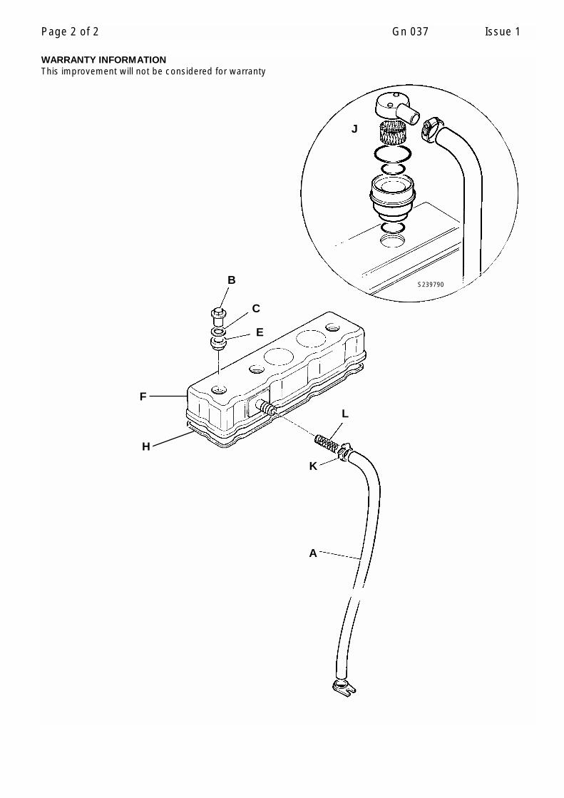
Page 2 of 2 Gn 037 Issue 1
WARRANTY INFORMATIONThis improvement will not be considered for warranty
C
B
E
F
H
A
K
J
S239790
L

SUBJECT: New ITL NAPSC Network
Introduction of a new service and parts support network for International Transmissions Limited from February 17th2002. All previous parts ordering through JCB Burlington, Canada and JCB Savannah USA will be discontinued, andnew accounts for each OEM will be opened with ITL NAPSC.
ITL North American Product Support Center, PO Box 1000, Harrow, Ontario, NOR 1GO.
Services available to the OEM – 1) 1 866 734 8562 (1 866 73 ITL NA) toll free number, Fax 519 738 3477, or e-mail [email protected]) Parts supply availability and pricing information- Contact Colin Sellick (ext. 226).3) Shipping out of Harrow, Ontario or USA address - PO Box 312547, Detroit MI 48231-2547.4) Help ensuring correct parts needed are identified.5) Technical support - contact Ron Peters (ext. 238).6) All Warranty claims to be submitted on the normal ITL claim form, but to be sent to NAPSC address for the
attention of Garth Doey. Claims will be loaded electronically onto the local database enabling the UK ITL servicedesk to view the claim simultaneously. Consequently, time to settlement of claims will be speeded up with targetof 15 to 45 days max.
7) Parts discount level - ITL list less 30%. Emergency parts orders shipped next Business day 5% Surcharge.Critical/VD (vehicle down) orders placed before 3.00 p.m. (local NAPSC time), shipped with 7% premium. 40%discount on stock orders, minimum value £5,000.00 (excluding shipping costs). Orders limited to 2 stock ordersper year and terms CIF at the OEM. Lead-time for stock orders despatch 6 weeks. Any type of shipping methodcan be specified and orders can be drop shipped to any address specified in North America.
Also Note the introduction of 3 New ITL Principal Service Centers
ITL PSC – California, Texas and Michigan.Approved for ITL Warranty repair work.Complete ITL component strip down, repair and test facilities available.Remanufactured units Competent to carry out repairs from the end user, subject to OEM approval.
Principal Service CentersLeaman Equipment Co.16550 Railroad Ave. (L)Morgan Hill CA 95037 Tel 408 778 9677 Fax 408 778 9646
CIA Machinery INC3199 West Danieldale StLancaster, TX 75134 Tel 972 224 5501 or 800 527 6406 Fax 972 224 8204
continued
Page 1 of 2
!! SAFETY NOTICE - Instructions in the Service Bulletins assume that theengineer has a sound knowledge of safety procedures and has been trained in themaintenance and repair of ITL equipment. If you are unsure or do not understandinformation contained in the Service Bulletins then ask your supervisor for advice.Remember SAFETY MUST COME FIRST.
Number Gn038
Issue 1
Date Jan 2002
THIS BULLETIN IS ISSUED FOR THE PURPOSE OF CIRCULATING TECHNICAL INFORMATION AND DOESNOT CONSTITUTE AN INSTRUCTION TO CARRY OUT WARRANTY REPAIRS ON MACHINES
ISSUED BY THE TECHNICAL SERVICE DEPARTMENT OF I.T.L., WREXHAM, CLWYD, LL13 9UF, UNITED KINGDOM
GGeenneerraallTECHNICALINFORMATION
INDEX

Page 2 of 2 Gn 038 Issue 1
Great Lakes Power Products2006 Tobsal CourtWarren, MI 48091 Tel 810 759 5500 Fax 810 759 0879
ITL Service Centers
Centers throughout USA and Canada. In the event of repair work needed contact ITL Service Department (KeithBridges) in UK (Tel 01144 1978 666513).
1) Approved for ITL Warranty work 2) Provide Support for OEM vehicle repairs.3) Competent to carry out repairs, for the end user, subject to ITL, and OEM approval.
OEM’s capable of carrying out repairs through their own dealership, should continue to operate as normal. Theymay find the ITL Principal Service Centers particularly useful in those cases where expert internal repairs arerequired.
OEM’s, with or without their own dealer back up, can take full advantage of the ITL Service Centers. However,before initially approaching a Service Center, we ask that our Service Department be contacted first in orderthat ITL can give the OEM or your customer an introduction and help ensure that the Service Centers are fully awareof any special instructions or needs you may have.
In any event of warranty being requested of a Service Center we ask that ITL authorize any work to be carried out.

SUBJECT: Safety precautions when an engine is cleaned
PRODUCTS AFFECTED: All Engines
TO BE CARRIED OUT: Information only
SERVICE INFORMATION:
Care should be taken when an engine is cleaned with the use of a high pressure hose.
Cautions:
• Do not wash an engine while it is running or it is hot. If cold cleaning fluids are applied to a hot engine, certaincomponents on the engine could be damaged.
• Leave the engine to cool for at least one hour and disconnect battery connections before cleaning.
• Do not wash any part of the Fuel Injection Pump.
• Ensure that the altemator, starter motor and any other electrical components are shielded and not directlycleaned by high pressure hose.
• Do not wash the Electrical Shut-off Solenoid (ESOS) or any electrical components of the FIP when the engine ishot.
If these cautions are ignored, the engine or certain components could be damaged, fail to operate and also make themanufacturer’s warranty invalid.
Page 1 of 1
!! SAFETY NOTICE - Instructions in the Service Bulletins assume that theengineer has a sound knowledge of safety procedures and has been trained in themaintenance and repair of ITL equipment. If you are unsure or do not understandinformation contained in the Service Bulletins then ask your supervisor for advice.Remember SAFETY MUST COME FIRST.
Number Gn039(JCB Gen 151)
Issue 1Date Sep 2002
GGeenneerraallTECHNICALINFORMATION
INDEX
THIS BULLETIN IS ISSUED FOR THE PURPOSE OF CIRCULATING TECHNICAL INFORMATION AND DOESNOT CONSTITUTE AN INSTRUCTION TO CARRY OUT WARRANTY REPAIRS ON MACHINES
ISSUED BY THE TECHNICAL SERVICE DEPARTMENT OF I.T.L., WREXHAM, CLWYD, LL13 9UF, UNITED KINGDOM