Technical Committee on Water Additives for Fire Control ...€¦ · Technical Committee on Water...
138
Technical Committee on Water Additives for Fire Control and Vapor Mitigation (WAB-AAA) Memorandum DATE: April 28-April 29, 2015 TO: Principal and Alternate Members of the Technical Committee on Water Additives for Fire Control and Vapor Mitigation (WAB – AAA) FROM: Jacqueline Wilmot, Fire Protection Engineer/NFPA Staff Liaison SUBJECT: AGENDA PACKAGE – NFPA 18/18A/1150 First Draft Meeting (F2016) Enclosed is the agenda for the NFPA 18/18A/1150 First Draft meeting of the Technical Committee on Water Additives for Fire Control and Vapor Mitigation, which will be held on Tuesday, April 28, through Wednesday, April 29, 2015 at Four Points Sheraton Norwood (next to FM Approvals). Please review the attached public inputs in advance, and if you have alternate suggestions, please come prepared with proposed language and respective substantiation. If you have any questions prior to the meeting, please do not hesitate to contact me at: Office: (617) 984-7498 E-mail: [email protected] For administrative questions, please contact Kim Shea at (617) 984 -7953. I look forward to working with everyone.
Transcript of Technical Committee on Water Additives for Fire Control ...€¦ · Technical Committee on Water...

Technical Committee on Water Additives for Fire Control and Vapor
Mitigation (WAB-AAA)
Memorandum
DATE: April 28-April 29, 2015 TO: Principal and Alternate Members of the Technical Committee on Water Additives for Fire
Control and Vapor Mitigation (WAB – AAA) FROM: Jacqueline Wilmot, Fire Protection Engineer/NFPA Staff Liaison SUBJECT: AGENDA PACKAGE – NFPA 18/18A/1150 First Draft Meeting (F2016)
Enclosed is the agenda for the NFPA 18/18A/1150 First Draft meeting of the Technical
Committee on Water Additives for Fire Control and Vapor Mitigation, which will be held on
Tuesday, April 28, through Wednesday, April 29, 2015 at Four Points Sheraton Norwood
(next to FM Approvals). Please review the attached public inputs in advance, and if you have
alternate suggestions, please come prepared with proposed language and respective
substantiation.
If you have any questions prior to the meeting, please do not hesitate to contact me at: Office: (617) 984-7498 E-mail: [email protected] For administrative questions, please contact Kim Shea at (617) 984 -7953. I look forward to working with everyone.

Technical Committee on Water Additives for Fire Control and Vapor Mitigation (WAB-AAA)
NFPA 18/18A/1150 First Draft Meeting (Fall 2016)
Tuesday, April 28, 2015 - Wednesday, April 29, 2015
Four Points Sheraton
1125 Boston Providence Turnpike, Norwood, MA 02062
AGENDA
1. Call to Order – 8:00 am (4/28)
2. Introduction and Attendance
3. Chairman Comments
4. Approval of Previous Meeting Minutes
5. Staff Liaison Presentation on NFPA’s new Revision Process and F2016 Cycle
6. NFPA Research Division Presentation on how the Research Foundation, One Stop Data Shop and Library can assist the Technical Committee
7. Review of Public Inputs, Research Foundation Report and Development of First Revisions
8. New Business
9. Adjourn Meeting – TBA
10. Tour of FM Approvals
Please submit requests for additional agenda items to the chair and staff liaison at least seven days prior to the meeting.

Technical Committee on Water Additives for Fire Control and Vapor Mitigation (WAB-AAA)
NFPA 18/18A/1150 First Draft Meeting (Fall 2016)
Tuesday, April 28, 2015 - Wednesday, April 29, 2015
Four Points Sheraton
1125 Boston Providence Turnpike, Norwood, MA 02062
Key Dates for the Fall 2016 Revision Cycle
Final Date for First Draft Meeting June 15, 2015 Posting of First Draft and TC Ballot August 3, 2015 Final date for Ballot Return August, 24, 2015 Post First Draft Report for Public Comment September 7, 2015 Public Comment Closing Date November, 16, 2015 Final Date for Second Draft Meeting May 2, 2016 Posting of Second Draft and TC Ballot June 13, 2016 Final Date for Ballot Return July 5, 2016 Final Second Draft Posted July 18, 2016 Closing Date for Notice of Intent to Make a Motion (NITMAM) August 22, 2016 Issuance of Consent Document (No NITMAMs) November 11, 2016 NFPA Annual Meeting June 2016 Issuance of Document with NITMAM August 10, 2017 Technical Committee deadlines are in bold.

Address List No PhoneWater Additives for Fire Control and Vapor Mitigation WAB-AAA
Jacqueline Wilmot04/24/2015
WAB-AAA
Armand V. Brandao
ChairFM ApprovalsHydraulics Group1151 Boston-Providence TurnpikePO Box 9102Norwood, MA 02062-9102Alternate: Robert M. Cordell
I 1/16/2003WAB-AAA
Michael T. Greiner
SecretaryHazard Control Technologies, Inc.150 Walter WayFayetteville, GA 30214-3999Alternate: Chris Champion
M 4/16/1999
WAB-AAA
Tracy Browder
PrincipalXCEL Energy600 South Tyler 21B26Amarillo, TX 79101Alternate: Anthony Natale
U 07/29/2013WAB-AAA
Brian R. Foster
PrincipalAEGIS Insurance Services, Inc.41 Freedom DriveMurphy, NC 28906
I 08/09/2012
WAB-AAA
Walter Groden
PrincipalAIG Property CasualtyGlobal Technical Office-Energy & Engineered Risk64 Seely PlaceScarsdale, NY 10583-2627
I 04/08/2015WAB-AAA
Cecilia W. Johnson
PrincipalUSDA Forest ServiceWildland Fire Chemical SystemsMissoula Technology & Development Center5785 Highway 10 WestMissoula, MT 59808
RT 7/16/2003
WAB-AAA
Blake M. Shugarman
PrincipalUL LLC333 Pfingsten RoadNorthbrook, IL 60062-2096Alternate: Jerauld R. Kirkpatrick
RT 11/2/2006WAB-AAA
Robert E. Tinsley, Jr.
PrincipalPyrocool Technologies, Inc.3540 South Amherst HighwayMonroe, VA 24574
M 4/28/2000
WAB-AAA
Qingsheng Wang
PrincipalOklahoma State University494 Cordell SouthStillwater, OK 74078-8016
SE 04/08/2015WAB-AAA
Gerald J. Halpin III
Voting AlternateCET Fire Pumps Manufacturing75 Hector Street, Box 90Pierville, QC J0G 1J0 CanadaFire Apparatus Manufacturers AssociationVoting Alt. to FAMA rep.
M 10/27/2009
WAB-AAA
Chris Champion
AlternateHazard Control Technologies, Inc.150 Walter WayFayetteville, GA 30214-3999Principal: Michael T. Greiner
M 03/03/2014WAB-AAA
Robert M. Cordell
AlternateFM Approvals1151 Boston-Providence TurnpikeNorwood, MA 02062-9102Principal: Armand V. Brandao
I 10/29/2012
1

Address List No PhoneWater Additives for Fire Control and Vapor Mitigation WAB-AAA
Jacqueline Wilmot04/24/2015
WAB-AAA
Jerauld R. Kirkpatrick
AlternateUl LLC333 Pfingsten RoadNorthbrook, IL 60062-2096Principal: Blake M. Shugarman
RT 08/11/2014WAB-AAA
Anthony Natale
AlternateConsolidated Edison of New York521 West 41st StreetNew York, NY 10036-6202Principal: Tracy Browder
U 04/08/2015
WAB-AAA
Jacqueline Wilmot
Staff LiaisonNational Fire Protection Association1 Batterymarch ParkQuincy, MA 02169-7471
02/04/2014
2

Friday 4 24, Friday
Water Additives for Fire Control and Vapor MitigationWAB-AAAName Representation Class Office
Distribution by %
Company
Armand V. Brandao FM Approvals FM I Chair
Brian R. Foster AEGIS Insurance Services, Inc. I Principal
Walter Groden AIG Property Casualty I Principal
3Voting Number Percent 30%
Michael T. Greiner Hazard Control Technologies, Inc. M Secretary
Robert E. Tinsley, Jr. Pyrocool Technologies, Inc. M Principal
Gerald J. Halpin III CET Fire Pumps Manufacturing FAMA M Voting Alternate
3Voting Number Percent 30%
Cecilia W. Johnson USDA Forest Service RT Principal
Blake M. Shugarman UL LLC UL RT Principal
2Voting Number Percent 20%
Qingsheng Wang Oklahoma State University SE Principal
1Voting Number Percent 10%
Tracy Browder XCEL Energy U Principal
1Voting Number Percent 10%
10Total Voting Number

Technical Committee on Water Additives for Fire Control and Vapor Mitigation (WAB-AAA)
NFPA 18/18A/1150 First Draft Meeting (Fall 2016)
Tuesday, April 28, 2015 - Wednesday, April 29, 2015
Four Points Sheraton
1125 Boston Providence Turnpike, Norwood, MA 02062
Staff Liaison Notice
Note from the Staff Liaison Dear Technical Committee Members: We are very pleased that you will be participating in the processing of the 2017 Edition of NFPA 18, 18A and 1150. Development of this document would not be possible without the participation of volunteers like you. Thank you! Meeting Preparation Committee members should review the published inputs prior to the meeting and to be prepared to act on each item. Handout materials should be submitted to the chair and staff liaison at least seven days prior to the meeting. Only one posting of the Public Inputs will be made; it will be arranged in section/order and will be pre-numbered. This will be posted to the NFPA 18/18A/1150 Document Information page (www.nfpa.org/18; www.nfpa.org/18A; www.nfpa.org/1150) under the “Next Edition” tab. If you are having trouble accessing the website, please contact Kim Shea at [email protected]. Mandatory Materials:
Last edition of the standard Meeting agenda Public Inputs Committee Officer’s Guide (Chairs) Roberts’ Rules of Order (Chair; An abbreviated version may be found in the
Committee Officer’s Guide)

Optional Materials: NFPA Annual Directory NFPA Manual of Style
Regulations and Guiding Documents All committee members are expected to behave in accordance with the Guide for the Conduct of Participants in the NFPA Codes and Standards Development Process. All actions during and following the committee meetings will be governed in accordance with the Regulations Governing the Development of NFPA Standards. Failure to comply with these could result in challenges to the standards-making process. A successful challenge on procedural grounds could prevent or delay publication of the document. The style of the document must comply with the Manual of Style for NFPA Technical Committee Documents.

Technical Committee on Water Additives for Fire and Vapor Mitigation (WAB-AAA)
NFPA 18/18A/1150 First Draft Meeting (Fall 2016)
Tuesday, April 28, through Wednesday, April 29, 2015
Four Points Sheraton
1125 Boston Providence Turnpike, Norwood, MA 02062
General Procedures for Meetings
Use of tape recorders or other means capable of producing verbatim transcriptions of any NFPA Committee Meeting is not permitted.
Attendance at all NFPA Committee Meetings is open. All guests must sign in and identify their affiliation.
Participation in NFPA Committee Meetings is generally limited to committee members and NFPA staff. Participation by guests is limited to individuals, who have received prior approval from the chair to address the committee on a particular item, or who wish to speak regarding public proposals or comments that they submitted.
The chairman reserves the right to limit the amount of time available for any presentation.
No interviews will be allowed in the meeting room at any time, including breaks.
All attendees are reminded that formal votes of committee members will be secured by letter ballot. Voting at this meeting is used to establish a sense of agreement, but only the results of the formal letter ballot will determine the official action of the committee.
Note to Special Experts: Particular attention is called to Section 3.3(e ) of the NFPA Guide for Conduct of Participants in the NFPA Codes and Standards Development Process in the NFPA Directory. This section requires committee members to declare any interest they may represent, other than their official designation as shown on the committee roster. This typically occurs when a special expert is trained by and represents another interest category on a particular subject. If such a situation exists on a specific issue or issues, the committee member shall declare those interest to the committee and refrain from voting on any action relating to those issues.
Smoke is not permitted at NFPA Committee Meetings.

TC on Water Additives for Fire Control & Vapor MitigationROC Meeting/WAB-AAA
NFPA Headquarters1 Batterymarch Park
Quincy, MA April 27, 2010
Attendees:
Armand Brandao (Chair) Michael GreinerDominic CollettiCharles GeorgeBlake ShugarmanLarry VandersallMark Cloutier (NFPA Staff Liaison)
1. The Committee Chair called the meeting to order at 8:00 a.m. Introductions were made.
2. The Chair and staff liaison presented their reports to the committee.
3. The minutes of the previous ROP meeting were reviewed and approved.
4. The committee then acted on the public and committee Comments. See the ROC for the official actions.
5. There was no old business.
6. There was no new business.
7. Meeting adjourned at 5:00 pm.

NFPA 18 Public Input

Public Input No. 1-NFPA 18-2012 [ Section No. 2.3.4 ]
2.3.4 UL Publications. Underwriters Laboratories Inc., 333 Pfingsten Road, Northbrook, IL 60062-2096.
UL 162, Standard for Foam Equipment and Liquid Concentrates, 1994, revised 1999.
ANSI/ UL 711/ULC S508, Rating and Fire Testing of Fire Extinguishers, 2004, revised 2007 2009 .
Statement of Problem and Substantiation for Public Input
Update referenced standard to most recent edition as indicated.
Submitter Information Verification
Submitter NFPA User ID: [email protected] Full Name: John BenderOrganization: Underwriters Laboratories Inc.Telephone:Street Address: City: State:Zip: Submittal Date: Wed Apr 18 13:39:08 EDT 2012
Copyright Assignment
I, John Bender, hereby irrevocably grant and assign to the National Fire Protection Association (NFPA) all and full rights in copyright in this Public Input (including both the Proposed Change and the Statement of Problem and Substantiation). I understand and intend that I acquire no rights, including rights as a joint author, in any publication of the NFPA in which this Public Input in this or another similar or derivative form is used. I hereby warrant that I am the author of this Public Input and that I have full power and authority to enter into this copyright assignment.
By checking this box I affirm that I am John Bender, and I agree to be legally bound by the above Copyright Assignment and the terms and conditions contained therein. I understand and intend that, by checking this box, I am creating an electronic signature that will, upon my submission of this form, have the same legal force and effect as a handwritten signature
Page 1 of 12National Fire Protection Association Report
3/30/2015http://submittals.nfpa.org/TerraViewWeb/ContentFetcher?commentParams=%28Comment...

Public Input No. 9-NFPA 18-2013 [ New Section after 3.3.6 ]
3.3.x Coupon. Coupon is a sample of metal or metalwork submitted to a customer or testing agency for review, examination, analysis, or approval.
Statement of Problem and Substantiation for Public Input
“Coupon” is used a number of times in the Standard yet there is no specific definition. A common use dictionary provides only the customary commonplace definition which is not within the context of how it is used in the Standard.
Submitter Information Verification
Submitter NFPA User ID: [email protected] Full Name: John ChartierOrganization: Northeastern Regional Fire CodTelephone:Street Address: City: State:Zip: Submittal Date: Thu Apr 11 08:22:23 EDT 2013
Copyright Assignment
I, John Chartier, hereby irrevocably grant and assign to the National Fire Protection Association (NFPA) all and full rights in copyright in this Public Input (including both the Proposed Change and the Statement of Problem and Substantiation). I understand and intend that I acquire no rights, including rights as a joint author, in any publication of the NFPA in which this Public Input in this or another similar or derivative form is used. I hereby warrant that I am the author of this Public Input and that I have full power and authority to enter into this copyright assignment.
By checking this box I affirm that I am John Chartier, and I agree to be legally bound by the above Copyright Assignment and the terms and conditions contained therein. I understand and intend that, by checking this box, I am creating an electronic signature that will, upon my submission of this form, have the same legal force and effect as a handwritten signature
Page 2 of 12National Fire Protection Association Report
3/30/2015http://submittals.nfpa.org/TerraViewWeb/ContentFetcher?commentParams=%28Comment...

Public Input No. 10-NFPA 18-2013 [ Section No. 4.1.1.3 ]
4.1.1.3Wetting agent concentrate shall be used at the prescribed proportion(s), in accordance with its listing(s).
Statement of Problem and Substantiation for Public Input
Requirement is already specified adequately in the more appropriate section of 4.4.
Submitter Information Verification
Submitter NFPA User ID: [email protected] Full Name: John ChartierOrganization: Northeastern Regional Fire CodTelephone:Street Address: City: State:Zip: Submittal Date: Thu Apr 11 08:23:23 EDT 2013
Copyright Assignment
I, John Chartier, hereby irrevocably grant and assign to the National Fire Protection Association (NFPA) all and full rights in copyright in this Public Input (including both the Proposed Change and the Statement of Problem and Substantiation). I understand and intend that I acquire no rights, including rights as a joint author, in any publication of the NFPA in which this Public Input in this or another similar or derivative form is used. I hereby warrant that I am the author of this Public Input and that I have full power and authority to enter into this copyright assignment.
By checking this box I affirm that I am John Chartier, and I agree to be legally bound by the above Copyright Assignment and the terms and conditions contained therein. I understand and intend that, by checking this box, I am creating an electronic signature that will, upon my submission of this form, have the same legal force and effect as a handwritten signature
Page 3 of 12National Fire Protection Association Report
3/30/2015http://submittals.nfpa.org/TerraViewWeb/ContentFetcher?commentParams=%28Comment...

Public Input No. 2-NFPA 18-2012 [ Section No. 6.2.2 ]
6.2.2 Tests shall be conducted according to the procedures detailed in this section and ANSI/ UL 711/ULC S508 for Class A fires utilizing a 3-A wood crib.
Statement of Problem and Substantiation for Public Input
Add ANSI approval designation toUL 300 as UL 300 is ANSI approved.
Submitter Information Verification
Submitter NFPA User ID: [email protected] Full Name: John BenderOrganization: Underwriters Laboratories Inc.Telephone:Street Address: City: State:Zip: Submittal Date: Wed Apr 18 13:40:37 EDT 2012
Copyright Assignment
I, John Bender, hereby irrevocably grant and assign to the National Fire Protection Association (NFPA) all and full rights in copyright in this Public Input (including both the Proposed Change and the Statement of Problem and Substantiation). I understand and intend that I acquire no rights, including rights as a joint author, in any publication of the NFPA in which this Public Input in this or another similar or derivative form is used. I hereby warrant that I am the author of this Public Input and that I have full power and authority to enter into this copyright assignment.
By checking this box I affirm that I am John Bender, and I agree to be legally bound by the above Copyright Assignment and the terms and conditions contained therein. I understand and intend that, by checking this box, I am creating an electronic signature that will, upon my submission of this form, have the same legal force and effect as a handwritten signature
Page 4 of 12National Fire Protection Association Report
3/30/2015http://submittals.nfpa.org/TerraViewWeb/ContentFetcher?commentParams=%28Comment...

Public Input No. 3-NFPA 18-2012 [ Section No. 7.2 ]
7.2 Listing. Wetting agent solutions at the concentrations specified by the manufacturer shall be evaluated to and comply with the requirements of ANSI/ UL 711/ULC S508 for Class B fires.
Statement of Problem and Substantiation for Public Input
Add ANSI approval designation to UL 711 as UL 711 is ANSI approved.
Submitter Information Verification
Submitter NFPA User ID: [email protected] Full Name: John BenderOrganization: Underwriters Laboratories Inc.Telephone:Street Address: City: State:Zip: Submittal Date: Wed Apr 18 13:41:41 EDT 2012
Copyright Assignment
I, John Bender, hereby irrevocably grant and assign to the National Fire Protection Association (NFPA) all and full rights in copyright in this Public Input (including both the Proposed Change and the Statement of Problem and Substantiation). I understand and intend that I acquire no rights, including rights as a joint author, in any publication of the NFPA in which this Public Input in this or another similar or derivative form is used. I hereby warrant that I am the author of this Public Input and that I have full power and authority to enter into this copyright assignment.
By checking this box I affirm that I am John Bender, and I agree to be legally bound by the above Copyright Assignment and the terms and conditions contained therein. I understand and intend that, by checking this box, I am creating an electronic signature that will, upon my submission of this form, have the same legal force and effect as a handwritten signature
Page 5 of 12National Fire Protection Association Report
3/30/2015http://submittals.nfpa.org/TerraViewWeb/ContentFetcher?commentParams=%28Comment...

Public Input No. 4-NFPA 18-2012 [ Section No. 7.3 ]
7.3 Test Method. Tests for Class B fires shall be conducted as follows:
(1) A 4.65 m2 (50 ft2) 20 B pan fitted as described in ANSI/ UL 711/ULC S508 with a backboard that is the width of the pan and 0.9 m (3 ft) high shall be used.
(2) A 51 mm (2 in.) layer of heptane fuel shall be floated on a 102 mm (4 in.) depth of water.
(3) The fuel in the pan shall be ignited and allowed to free burn for 60 seconds.
(4) A 37.9 L/min (10 gpm) nozzle shall be used to apply the wetting agent solution to the fire using one, or a combination, of the following methods:
(a) The nozzle shall be fixed in position at an angle above the horizontal in order to direct the discharge across the pan onto thebackboard for the entire duration of the test.
(b) The nozzle shall be permitted to be moved as necessary for control and extinguishment.
(5) In no case shall the nozzle extend over any part of the test pan.
(6) The fire shall be extinguished within 5 minutes of the start of application of the wetting agent solution.
Statement of Problem and Substantiation for Public Input
Add ANSI approval designation to UL 711 as UL 711 is ANSI approved.
Submitter Information Verification
Submitter NFPA User ID: [email protected] Full Name: John BenderOrganization: Underwriters Laboratories Inc.Telephone:Street Address: City: State:Zip: Submittal Date: Wed Apr 18 13:42:43 EDT 2012
Copyright Assignment
Page 6 of 12National Fire Protection Association Report
3/30/2015http://submittals.nfpa.org/TerraViewWeb/ContentFetcher?commentParams=%28Comment...
I, John Bender, hereby irrevocably grant and assign to the National Fire Protection Association (NFPA) all and full rights in copyright in this Public Input (including both the Proposed Change and the Statement of Problem and Substantiation). I understand and intend that I acquire no rights, including rights as a joint author, in any publication of the NFPA in which this Public Input in this or another similar or derivative form is used. I hereby warrant that I am the author of this Public Input and that I have full power and authority to enter into this copyright assignment.
By checking this box I affirm that I am John Bender, and I agree to be legally bound by the above Copyright Assignment and the terms and conditions contained therein. I understand and intend that, by checking this box, I am creating an electronic signature that will, upon my submission of this form, have the same legal force and effect as a handwritten signature
Page 7 of 12National Fire Protection Association Report
3/30/2015http://submittals.nfpa.org/TerraViewWeb/ContentFetcher?commentParams=%28Comment...

Public Input No. 5-NFPA 18-2012 [ Section No. A.4.2.3.2 ]
A.4.2.3.2 Fire test requirements for protection of commercial cooking equipment are addressed by ANSI/ UL 300 for fixed fire extinguishing systems. The fire protection requirements for combustible cooking media protection areaddressed under NFPA 17 and NFPA 17A.
Statement of Problem and Substantiation for Public Input
Add ANSI approval designation to UL 300 as UL 300 is ANSI approved.
Submitter Information Verification
Submitter NFPA User ID: [email protected] Full Name: John BenderOrganization: Underwriters Laboratories Inc.Telephone:Street Address: City: State:Zip: Submittal Date: Wed Apr 18 13:43:50 EDT 2012
Copyright Assignment
I, John Bender, hereby irrevocably grant and assign to the National Fire Protection Association (NFPA) all and full rights in copyright in this Public Input (including both the Proposed Change and the Statement of Problem and Substantiation). I understand and intend that I acquire no rights, including rights as a joint author, in any publication of the NFPA in which this Public Input in this or another similar or derivative form is used. I hereby warrant that I am the author of this Public Input and that I have full power and authority to enter into this copyright assignment.
By checking this box I affirm that I am John Bender, and I agree to be legally bound by the above Copyright Assignment and the terms and conditions contained therein. I understand and intend that, by checking this box, I am creating an electronic signature that will, upon my submission of this form, have the same legal force and effect as a handwritten signature
Page 8 of 12National Fire Protection Association Report
3/30/2015http://submittals.nfpa.org/TerraViewWeb/ContentFetcher?commentParams=%28Comment...

Public Input No. 8-NFPA 18-2012 [ Section No. A.4.2.5 ]
A.4.2.5 Fire test requirements for protection of Class D hazards are addressed by ANSI/ UL 711/ULC S508.
Different wetting agent concentrates and their solutions can be incompatible. Such incompatibilities can result in any or all of, but are not be limited to, the following conditions:
(1) Loss of fire-fighting performance
(2) Coagulation or jelling of the concentrate or solution, which can alter flow
(3) Improper proportioning rates(4) Increased corrosion or other structural damage
(5) Inability to maintain a stable solution
Provided that the blending and application of water agent and water additive solutions is conducted using separate delivery equipment (to avoid the potential conditions noted in the preceding list), it can be beneficial to apply more than one type of wetting agent and/or water additive solution (including conventional foam solutions as governed by NFPA 11 and NFPA 1150), to take advantage of different product features and benefits.
It can be beneficial to use two or more different technologies to suppress a fire. For example, apply a wetting agent solution on a three-dimensional fuel fire to achieve suppression and then apply a conventional Class B foam blanket to provide an extra margin of safety and additional exposure protection for the resulting pooled fuel collected underneath the three-dimensional object.
Every care should be taken to avoid applying divergent technologies together, directed at the same delivery point or target, to avoid one product interfering with another, rendering one or both less effective.
Statement of Problem and Substantiation for Public Input
Add ANSI approval designation to UL 711 as UL 711 is ANSI approved.
Submitter Information Verification
Submitter NFPA User ID: [email protected] Full Name: John BenderOrganization: UL LLCTelephone:Street Address: City:State:Zip: Submittal Date: Tue Jun 26 09:58:25 EDT 2012
Page 9 of 12National Fire Protection Association Report
3/30/2015http://submittals.nfpa.org/TerraViewWeb/ContentFetcher?commentParams=%28Comment...

Copyright Assignment
I, John Bender, hereby irrevocably grant and assign to the National Fire Protection Association (NFPA) all and full rights in copyright in this Public Input (including both the Proposed Change and the Statement of Problem and Substantiation). I understand and intend that I acquire no rights, including rights as a joint author, in any publication of the NFPA in which this Public Input in this or another similar or derivative form is used. I hereby warrant that I am the author of this Public Input and that I have full power and authority to enter into this copyright assignment.
By checking this box I affirm that I am John Bender, and I agree to be legally bound by the above Copyright Assignment and the terms and conditions contained therein. I understand and intend that, by checking this box, I am creating an electronic signature that will, upon my submission of this form, have the same legal force and effect as a handwritten signature
Page 10 of 12National Fire Protection Association Report
3/30/2015http://submittals.nfpa.org/TerraViewWeb/ContentFetcher?commentParams=%28Comment...

Public Input No. 7-NFPA 18-2012 [ Section No. A.8.2.2 ]
A.8.2.2 Where such equipment is also used to take suction from a hydrant supplied by potable water supply , extra care should be exercised to prevent contamination of potable water supplies with the wetting agent concentrate orsolution.
Statement of Problem and Substantiation for Public Input
The extra care needed to assure no contamination of a potable supply should be exercised regardless if that supply comes through a hydrant or not.
Submitter Information Verification
Submitter NFPA User ID: [email protected] Full Name: Arthur LondenskyOrganization: Northeastern Regional Fire CodTelephone:Street Address: City: State:Zip: Submittal Date: Thu Apr 26 07:37:56 EDT 2012
Copyright Assignment
I, Arthur Londensky, hereby irrevocably grant and assign to the National Fire Protection Association (NFPA) all and full rights in copyright in this Public Input (including both the Proposed Change and the Statement of Problem and Substantiation). I understand and intend that I acquire no rights, including rights as a joint author, in any publication of the NFPA in which this Public Input in this or another similar or derivative form is used. I hereby warrant that I am the author of this Public Input and that I have full power and authority to enter into this copyright assignment.
By checking this box I affirm that I am Arthur Londensky, and I agree to be legally bound by the above Copyright Assignment and the terms and conditions contained therein. I understand and intend that, by checking this box, I am creating an electronic signature that will, upon my submission of this form, have the same legal force and effect as a handwritten signature
Page 11 of 12National Fire Protection Association Report
3/30/2015http://submittals.nfpa.org/TerraViewWeb/ContentFetcher?commentParams=%28Comment...
Public Input No. 6-NFPA 18-2012 [ Section No. B.1.2.1 ]
B.1.2.1 UL Publications. Underwriters Laboratories Inc., 333 Pfingsten Road, Northbrook, IL 60062-2096.
ANSI/ UL 300, Standard for Fire Testing of Fire Extinguishing Systems for Protection of Commercial Cooking Equipment, 2005, Revised 2010 .
ANSI/ UL 711/ULC S508, Rating and Testing of Fire Extinguishers, 2004, revised 2007 2009 .
Statement of Problem and Substantiation for Public Input
Add ANSI approval designation to UL 300 and UL 711 as these standards are ANSI approved. Update referenced standards to most recent edition as indicated.
Submitter Information Verification
Submitter NFPA User ID: [email protected] Full Name: John BenderOrganization: Underwriters Laboratories Inc.Telephone:Street Address: City: State:Zip: Submittal Date: Wed Apr 18 13:46:11 EDT 2012
Copyright Assignment
I, John Bender, hereby irrevocably grant and assign to the National Fire Protection Association (NFPA) all and full rights in copyright in this Public Input (including both the Proposed Change and the Statement of Problem and Substantiation). I understand and intend that I acquire no rights, including rights as a joint author, in any publication of the NFPA in which this Public Input in this or another similar or derivative form is used. I hereby warrant that I am the author of this Public Input and that I have full power and authority to enter into this copyright assignment.
By checking this box I affirm that I am John Bender, and I agree to be legally bound by the above Copyright Assignment and the terms and conditions contained therein. I understand and intend that, by checking this box, I am creating an electronic signature that will, upon my submission of this form, have the same legal force and effect as a handwritten signature
Page 12 of 12National Fire Protection Association Report
3/30/2015http://submittals.nfpa.org/TerraViewWeb/ContentFetcher?commentParams=%28Comment...

NFPA 18A Public Input – None Received

NFPA 1150 Public Input

Public Input No. 2-NFPA 1150-2014 [ Chapter 2 ]
Chapter 2 Referenced Publications2.1 General.
The documents or portions thereof listed in this chapter are referenced within this standard and shall be considered part of the requirements of this document.2.2 NFPA Publications.
(Reserved)2.3 Other Publications.2.3.1 ASTM Publications.
ASTM International, 100 Barr Harbor Drive, P.O. Box C700, West Conshohocken, PA 19428-2959.
ASTM D 92, Standard Test Method for Flash and Fire Points by Cleveland Open Cup Tester, 2002 2012b .
ASTM D 97, Standard Test Method for Pour Point of Petroleum Products, 2002 2012 .
ASTM D 1331, Standard Test Methods for Surface and Interfacial Tension of Solutions of Surface-Active Agents, 2001, reinstated 2011 .
ASTM D 2196, Standard Test Methods for Rheological Properties of Non-Newtonian Materials by Rotational (Brookfield type) Viscometer, 2010.ASTM D 2281, Standard Test Method for Evaluation of Wetting Agents by the Skein Test, 1997 2010 .
ASTM D 4976, Standard Specification for Polyethylene Plastics Molding and Extrusion Materials, 2002 2012B .
ASTM E 3, Standard Practice for Preparation of Metallographic Specimens, 2001 2011 .
ASTM E 407, Standard Practice of Microetching Metals and Alloys, 19992011 e1 .ASTM E 729, Standard Guide for Conducting Acute Toxicity Tests on Test Materials with Fishes, Macroinvertebrates, and Amphibians, 1996, reapproved 2007 .
ASTM E 1321, Standard Test Method for Determining Material Ignition and Flame Spread Properties, 1997(02) 2013 .2.3.2 ISO Publications.
International Standards Organization, 1 rue de Varembé, Case Postale 56, CH-1211, Genève 20, Switzerland.
ISO 304, Surface Active Agents — Determination of Surface Tension by Drawing Up Liquid Films, 2nd edition, 1985.
ISO 17025, General Requirements for the Competence of Testing and Calibration Laboratories, 2006.2.3.3 NACE Publications.
NACE International, 1440 South Creek Drive, Houston, TX 77084-4906.
NACE TM0169, Standard Test Method — Laboratory Corrosion Testing of Metals, 2000 2012 .
Page 1 of 6National Fire Protection Association Report
3/30/2015http://submittals.nfpa.org/TerraViewWeb/ContentFetcher?commentParams=%28Comment...

2.3.4 OECD Publications.Organization for Economic Co-operation and Development, 2, rue André-Pascal, 75775 Paris Cedex 16, France.OECD Principles of Good Laboratory Practice, Annex 2, C(89)87(Final).
2.3.5 SAE Publications.Society of Automotive Engineers SAE International , 400 Commonwealth Drive, Warrendale, PA 15096.
SAE AMS-3208, Chloroprene (Cr) Rubber, Weather Resistant, 45-55, November 1998 2014 .SAE AMS-C-9084, Cloth, Glass, Finished for Resin Laminates, June 1999,reaffirmed 2013 .
SAE AMS-DTL-23053/5, Insulation Sleeving, Electrical, Heat Shrinkable,Polyolefin, Flexible Crosslinked, July 1999 2012 .
SAE AMS-S-8802, Sealing Compound, Temperature Resistant, Integral Fuel Tanks and Fuel Cell Cavities, High Adhesion, January 2003 2011 .
2.3.6 U.S. EPA Publications.Environmental Protection Agency, National Service Center for Environmental Publications (NSCEP), P.O. Box 42419, Cincinnati, OH 45242. Also available at http://www.epa.gov/ncepihom/nepishom/.
OPPTS 835.3110, Ready Biodegradability, Section M, CO 2 Evolution(Modified Sturm), Test, Fate, Transport and Transformation Test Guidelines,January 1998.OPPTS 850.1075, Fish Acute Toxicity Test, Freshwater and Marine, Ecological Effects Test Guidelines, April 1996.
OPPTS 870.1100, Acute Oral Toxicity, Health Effects Test Guidelines, August 1998.
OPPTS 870.1200, Acute Dermal Toxicity, Health Effects Test Guidelines, August 1998.
OPPTS 870.2400, Acute Eye Irritation, Health Effects Test Guidelines, August 1998.
OPPTS 870.2500, Acute Dermal Irritation, Health Effects Test Guidelines, August 1998.
2.3.7 U.S. Government Publications.U.S. Government Printing Office, Washington, DC 20402.
Title 40, Code of Federal Regulations, Part 160, “Good Laboratory Practice Standards.”
Title 40, Code of Federal Regulations, Part 792, “Good Laboratory Practice Standards.”Federal Test Standard No. 601, Methods 3021 and 3025 (April 12, 1985).
Wildland Fire Chemicals Standard Test Procedures, STP-2.2, Lateral Ignition and Flame Spread Test, U.S.D.A. Forest Service, May 30, 2007.
2.3.8 U.S. Military Specifications.Standardization Documents Order Desk, Building 4D, 700 Robbins Ave., Philadelphia, PA 19111-5094. Also available at http://stinet.dtic.mil/ .MIL-A-A-55859A, Tube, Nonmetallic; Polyvinyl Chloride (PVC) Flexible (General Use), October 31, 2002.
MIL-PRF-81733D, Sealing and Coating Compound, Corrosion Inhibitive, May 15, 1998.
Page 2 of 6National Fire Protection Association Report
3/30/2015http://submittals.nfpa.org/TerraViewWeb/ContentFetcher?commentParams=%28Comment...
2.3.9 Other Publications.Merriam-Webster’s Collegiate Dictionary, 11th edition, Merriam-Webster, Inc., Springfield, MA, 2003.2.4 References for Extracts in Mandatory Sections.
NFPA 472, Standard for Competence of Responders to Hazardous Materials/Weapons of Mass Destruction Incidents, 2008 edition 2013 .
Statement of Problem and Substantiation for Public Input
Referenced current editions.
Related Public Inputs for This Document
Related Input RelationshipPublic Input No. 3-NFPA 1150-2014 [Chapter B]
Submitter Information Verification
Submitter NFPA User ID: [email protected] Full Name: Aaron AdamczykOrganization: [ Not Specified ]Telephone:Street Address: City:State:Zip: Submittal Date: Mon Jun 23 23:49:10 EDT 2014
Copyright Assignment
I, Aaron Adamczyk, hereby irrevocably grant and assign to the National Fire Protection Association (NFPA) all and full rights in copyright in this Public Input (including both the Proposed Change and the Statement of Problem and Substantiation). I understand and intend that I acquire no rights, including rights as a joint author, in any publication of the NFPA in which this Public Input in this or another similar or derivative form is used. I hereby warrant that I am the author of this Public Input and that I have full power and authority to enter into this copyright assignment.
By checking this box I affirm that I am Aaron Adamczyk, and I agree to be legally bound by the above Copyright Assignment and the terms and conditions contained therein. I understand and intend that, by checking this box, I am creating an electronic signature that will, upon my submission of this form, have the same legal force and effect as a handwritten signature
Page 3 of 6National Fire Protection Association Report
3/30/2015http://submittals.nfpa.org/TerraViewWeb/ContentFetcher?commentParams=%28Comment...

Public Input No. 3-NFPA 1150-2014 [ Chapter B ]
Annex B Informational ReferencesB.1 Referenced Publications.The documents or portions thereof listed in this annex are referenced within the informational sections of this standard and are not part of the requirements of this document unless also listed in Chapter 2 for otherreasons.B.1.1 NFPA Publication.
National Fire Protection Association, 1 Batterymarch Park, Quincy, MA 02169-7471.NFPA 1145, Guide for the Use of Class A Foams in Manual Structural Fire Fighting, 2006 edition 2011 .
B.1.2 Other Publications.B.1.2.1 ASTM Publications.
ASTM International, 100 Barr Harbor Drive, P.O. Box C700, West Conshohocken, PA 19428-2959.
ASTM E 729, Standard Guide for Conducting Acute Toxicity Tests on Test Materials with Fishes, Macroinvertebrates, and Amphibians, 1996, reinstated2011 .
B.1.2.2 U.S. EPA Publications.Environmental Protection Agency, National Service Center for Environmental Publications (NSCEP), P.O. Box 42419, Cincinnati, OH 45242. Also available at http://www.epa.gov/ncepihom/nepishom/.
OPPTS 835.3110, Ready Biodegradability, Section M, CO 2 Evolution(Modified Sturm), Test, Fate, Transport and Transformation Test Guidelines,January 1998.B.1.2.3 U.S. Government Publications.
Program Leader, Wildland Fire Chemical Systems, U.S.D.A. Forest Service, 5785 Highway 10 West, Missoula, MT 59808.
“Chemicals Used in Wildland Fire Suppression: A Risk Assessment,” Labat-Anderson Incorporated for U.S.D.A. Forest Service, Intermountain Fire Sciences Laboratory, July 1996.“Ecological Risk Assessment: Wildland Fire-Fighting Chemicals,” Labat-Anderson Incorporated for U.S.D.A. Forest Service, Missoula Technology andDevelopment Center, 2004.
“Human Health Risk Assessment: Wildland Fire-Fighting Chemicals,” Labat-Anderson Incorporated for U.S.D.A. Forest Service, Missoula Technology and Development Center, January 22, 2003 (with March 6, 2003 revisions).
Wildland Fire Chemicals Standard Test Procedures, STP-2.2, Lateral Ignition and Flame Spread Test, U.S.D.A. Forest Service, May 30, 2007.
B.2 Informational References.The following documents or portions thereof are listed here as informationalresources only. They are not a part of the requirements of this document.B.2.1
The following documents provide additional information on foam development and application.
Page 4 of 6National Fire Protection Association Report
3/30/2015http://submittals.nfpa.org/TerraViewWeb/ContentFetcher?commentParams=%28Comment...
Coletti, Dominic J., Class A Foam — Best Practice for Structural Fire Fighters, Lyons Publishing, Royersford, PA, 1998.
Coletti, Dominic J., Davis, Larry, Foam Firefighting Operations 1, Essentials of Class A Foam— Awareness Level, Lyons Publishing, Royersford, PA, 2002.
Foam vs. Fire: Primer. Boise, ID: National Interagency Fire Center; National Wildfire Coordinating Group, NFES 2270, 1992.Foam vs. Fire: Class A Foam for Wildland Fires. Boise, ID: National Interagency Fire Center; National Wildfire Coordinating Group, NFES 2246, 1993.
Foam vs. Fire: Aerial Application. Boise, ID: National Interagency Fire Center; National Wildfire Coordinating Group, NFES 1845, 1995.
Liebson, John. An Introduction to Class A Foam and Compressed Air Foam Systems. Stafford, VA: International Society of Fire Service Instructors (IFSI), 1993.
Principles of Foam Fire Fighting, Fire Protection Publications, Oklahoma State University, Stillwater, OK, 2nd ed., 2003.
“Proceedings: International Wildland Fire Foam Symposium.” Chalk River, Ontario, Canada: Forestry Canada, Publication Distribution Centre, 1994.
B.3 References for Extracts in Informational Sections. (Reserved)
Statement of Problem and Substantiation for Public Input
Referenced current editions.
Related Public Inputs for This Document
Related Input RelationshipPublic Input No. 2-NFPA 1150-2014 [Chapter 2] Referenced current editions.
Submitter Information Verification
Submitter NFPA User ID: [email protected] Full Name: Aaron AdamczykOrganization: [ Not Specified ]Telephone:Street Address: City:State:Zip: Submittal Date: Tue Jun 24 00:45:22 EDT 2014
Copyright Assignment
I, Aaron Adamczyk, hereby irrevocably grant and assign to the National Fire Protection Association (NFPA) all and full rights in copyright in this Public Input (including both the Proposed Change and the Statement of Problem and Substantiation). I understand and intend that I acquire no rights, including rights as a joint author, in any publication of the NFPA in which this Public Input in this or another similar or derivative form is used. I hereby warrant that I am the author of this Public Input and that I have full power and authority to enter into this copyright assignment.
Page 5 of 6National Fire Protection Association Report
3/30/2015http://submittals.nfpa.org/TerraViewWeb/ContentFetcher?commentParams=%28Comment...

By checking this box I affirm that I am Aaron Adamczyk, and I agree to be legally bound by the above Copyright Assignment and the terms and conditions contained therein. I understand and intend that, by checking this box, I am creating an electronic signature that will, upon my submission of this form, have the same legal force and effect as a handwritten signature
Page 6 of 6National Fire Protection Association Report
3/30/2015http://submittals.nfpa.org/TerraViewWeb/ContentFetcher?commentParams=%28Comment...

Evaluation of Water Additives for Fire Control and
Vapor Mitigation-Phase II, Two and Three Dimensional
Class B Fire Tests
Final Report
Prepared by:
Joseph L. Scheffey, Vice President
Matthew E. Benfer, Engineer
Hughes Associates, Inc.
3610 Commerce Dr., Suite 817
Baltimore, MD 21227 www.haifire,com
© September 2014 Fire Protection Research Foundation
THE FIRE PROTECTION RESEARCH FOUNDATION
ONE BATTERYMARCH PARK
QUINCY, MASSACHUSETTS, U.S.A. 02169-7471
E-MAIL: [email protected]
WEB: www.nfpa.org/Foundation

—— Page ii ——

—— Page iii ——
FOREWORD
The goal of this Phase II project was to provide a repeatable and reproducible evaluation
methodology for the performance characteristics of water additives used in fixed fire protection
systems for fire control and vapor mitigation, as compared to a baseline of water-only
performance for Class B applications involving two and three dimensional liquid fuel fires. The
results of this Phase II project will be of direct benefit to the NFPA Technical Committees
responsible for NFPA 18A, Standard on Water Additive for Fire Control and Vapor Mitigation,
and NFPA 15, Standard for Water Spray Fixed Systems for Fire Protection. This effort also
relates to application oriented documents that address Class B hazards involving two and three
dimensional liquid fuel fires, such as NFPA 850, Recommended Practice for Fire Protection for
Electric Generating Plants and High Voltage Direct Current Converter Stations.
The Research Foundation expresses gratitude to the report author Joseph L. Scheffey, Vice
President and Matthew E. Benfer, who is with Hughes Associates, Inc. located in 3610 Commerce
Dr., Suite 817, Balitmore, MD 21227. The Research Foundation appreciates the guidance
provided by the Project Technical Panelists, the funding provided by the project sponsors, and all
others that contributed to this research effort. Thanks are also expressed to the National Fire
Protection Association (NFPA) for providing the project funding through the NFPA Annual Code
Fund.
The content, opinions and conclusions contained in this report are solely those of the authors.
About the Fire Protection Research Foundation
The Fire Protection Research Foundation plans, manages, and communicates research on a broad
range of fire safety issues in collaboration with scientists and laboratories around the world. The
Foundation is an affiliate of NFPA.
About the National Fire Protection Association (NFPA)
NFPA is a worldwide leader in fire, electrical, building, and life safety. The mission of the
international nonprofit organization founded in 1896 is to reduce the worldwide burden of fire and
other hazards on the quality of life by providing and advocating consensus codes and standards,
research, training, and education. NFPA develops more than 300 codes and standards to minimize
the possibility and effects of fire and other hazards. All NFPA codes and standards can be viewed
at no cost at www.nfpa.org/freeaccess.
Keywords: Fire scenarios, water additives, measures of performance

—— Page iv ——

—— Page ii ——
Water Additives Project
Project Technical Panel
Jeff Harrington, Harrington Group
Joseph Senecal, Kidde Fenwal
Don Birchler, FP&C Consultants
Benjamin Truchot, Ineris
Ken Dungan, Risk Technologies
Sponsoring Organizations
David Miller, AEGIS Insurance
John Reiter, AES Global Insurance
James Biggins, Global Risk Consultants
Michael Greiner, Hazard Control Technologies
Robert Taylor, PRB Coal Users Group
Blake Shugarman, Underwriters Laboratories
Tracy Browder, Xcel Energy
Steven Behrens, XL Global Asset Protection

—— Page vi ——

FIRE SCIENCE & ENGINEERING
Evaluation of Water Additives for Fire Control and Vapor Mitigation – Phase II, Two and Three Dimensional Class B Fire Tests
Prepared for
The Fire Protection Research Foundation One Batterypark Plaza
Quincy, MA 02169
Prepared by
Joseph L. Scheffey, Vice President Matthew E. Benfer, Engineer
Hughes Associates 3610 Commerce Drive, Suite 817
Baltimore, MD 21227 www.haifire.com
Daniel Steppan, Staff Engineer UL, LLC
333 Pfingsten Road Northbrook, IL 60062-2096
www.ul.com
FINAL REPORT September 15, 2014

WATER ADDITIVES TEST REPORT 1JLS00032.001 PAGE ii
HUGHES ASSOCIATES
TABLE OF CONTENTS
Page
1.0 BACKGROUND ......................................................................................................................... 1
2.0 TEST SETUP ............................................................................................................................. 2
2.1. Fire Scenarios ............................................................................................................... 2
2.2. Water Additives ............................................................................................................ 5
2.3. Water Additives System ............................................................................................... 6
2.4. Instrumentation ............................................................................................................ 8
3.0 TEST PROCEDURES .............................................................................................................. 10
4.0 RESULTS ................................................................................................................................ 11
4.1. Measures of Performance .......................................................................................... 11
4.2. Test Parameters .......................................................................................................... 14
4.3. Fire Suppression and Cooling Performance ............................................................ 15
4.3.1. 2D Fires 15
4.3.2. 3D Fires 17
4.3.3. Combined 2D and 3D Fires ............................................................................... 19
5.0 DISCUSSION ........................................................................................................................... 22
5.1. Additional Analysis .................................................................................................... 22
5.2. Threat Analysis ........................................................................................................... 24
5.3. Test Scenario .............................................................................................................. 26
6.0 CONCLUSIONS ....................................................................................................................... 26
7.0 ACKNOWLEDGEMENTS ........................................................................................................ 27
8.0 REFERENCES ......................................................................................................................... 27
APPENDIX A – FLAME HEIGHT VS. TIME AFTER IGNITION ........................................................... 29
APPENDIX B – HEAT FLUX VS. TIME AFTER IGNITION.................................................................. 40
APPENDIX C – CEILING AIR TEMPERATURES VS. TIME AFTER IGNITION .................................. 60
APPENDIX D – BEAM TEMPERATURES VS. TIME AFTER IGNITION ............................................. 80

WATER ADDITIVES TEST REPORT 1JLS00032.001 PAGE 1
HUGHES ASSOCIATES
1.0 BACKGROUND
Various water additives are available in today’s marketplace that claim to provide advantageous performance characteristics for fire control and vapor mitigation. Of particular interest are additives that report to provide superior fire suppression capabilities through emulsification or encapsulation. However, a scientific assessment of these various additives is lacking, and the fire protection community would benefit from an evaluation of the various available water additives for fire control and vapor mitigation.
In Phase I, a comprehensive evaluation of water additives used for fire control and vapor mitigation was performed [1]. The intent was to clarify the fire protection benefit of using water with additives for fire suppression versus water without additives. It was found that users of water additives have performance criteria for most scenarios of interest, as established by NFPA 18A [2]. Suppression criteria based on fire performance, as opposed to chemical/physical parameters of an agent, was emphasized. Based on the available data and the interests of the Sponsors and Technical Panel, a plan was developed to test representative water additives with fire scenarios of interest. These included a Class A deep-seated coal and combined two- and three-dimensional (2D/3D) Class B scenarios. A combined 2D/3D fire test scenario was identified based on demonstrated scalability of the 2D fire, and demonstrated experience with the 3D fuel cascade mockup.
The Sponsors and Technical Panel agreed that a Class B scenario was of most interest. It was desired to use a test scenario that could be associated with real-life conditions, not just as a scaled down scenario. Initial protection criteria might then be developed which could be directly applied to the power industry and other industrial settings having similar scenarios. A basic decision was made to evaluate representative water additive agents against Class B fire threats using a test mock-up which provided a generic, comparative analysis between water and water additives. An exact installation scenario was not replicated, although the scale was similar to an actual installation. It was decided to conceptually adopt a cascading fuel apparatus and associated pan/pool fire. A fixed overhead sprinkler nozzle array was to be evaluated, simulating current guidance in NFPA 850, Section 7.7.4.1.1 to provide 0.30 gpm/ft2 water application to Class B turbine pedestal situations and other associated Class B hazards in a power plant [3].
Prior demonstrations of a water additive showed that it might be more effective than plain water in suppressing a two dimensional pool fire. A three dimensional fire created by the running fuel cascade represents a significant challenge to water and water with additives. The disturbance of the fuel surface and continuous addition of burning fuel provide re-ignition sources that challenge any additive interaction with on the fuel surface. The Technical Panel decided that it was important to include the three dimensional fire aspect in the Class B evaluation. The Technical Panel decided that an appropriate fuel would have a moderate flash point, e.g., No. 2 diesel or similar (flash point on the order of 125–150ºF).
During these tests, water and three representative additives were applied from an array located above the fire area, similar to an installed sprinkler system. The original test concept was to determine, utilizing a bracketing technique, the minimum flow rate (application rate, gpm/ft2) required to extinguish the fire. The flow rate would be varied between successive tests until the least flow rate to cause suppression/extinguishment occurs. The performance enhancement associated with the additives would be evaluated by comparison with water alone. Successive tests were to be conducted on just the pool fire, and the pool fire with the running fuel cascade.
Due to budget constraints, a full parametric study to bracket the water additive application rate resulted in too many tests. In the original plan, a series of closely spaced sprinkler lines and nozzle outlets were to be positioned over the Class B fire threat. This would allow for relatively easy changes in nozzle spacing and associated application rates. The use of generic spray nozzles was anticipated to, hopefully, eliminate any variations associated with nozzle discharge characteristics.

WATER ADDITIVES TEST REPORT 1JLS00032.001 PAGE 2
HUGHES ASSOCIATES
A modified approach was selected and approved by the Sponsors and Technical Panel. An adaptation of the UL 162 foam sprinkler test was used [4]. Based on an initial version of the test plan, and iterative discussions and ROM cost estimates, Underwriters Laboratories (UL) was selected as the laboratory for these tests. Comments and input from the project Technical Panel were incorporated into the final test plan [5]. This test series, with the results described in this report, represented a balance of in-field system realism, number of agents to test, test setup, and time required to complete the tests.
2.0 TEST SETUP
2.1. Fire Scenarios
The three fire scenarios used in this test series were: (1) a two-dimensional pool fire, (2) a three-dimensional Class B flowing fuel fire, and (3) a three-dimensional Class B flowing fuel fire within a two-dimensional pool fire.
The Class B pool fire area was 50 ft2 (7.07 ft on a side); the height of the pan was 1.0 ft. Initially, the pan was filled with 20 gal of diesel which was approximately 5/8 in. deep. After Test 1 this was increased to a fuel layer thickness of 1.0 in. (~31 gal). For every test, the pan was filled with water such that the freeboard height (i.e., the height between the top lip of the pan and the top of the fuel) was 8.0 in. The test pan was self-leveling such that the free-board height remained relatively constant throughout the test. An elbow and pipe connected to the bottom of the pan drained off the leveling water as fuel from the cascade and water from the sprinklers accumulated in the pan. Initially the pan incorporated 0.5 gal of heptane on top of the diesel as an accelerant to increase flame spread across the pool. After Test 1, this amount was later reduced to 0.25 gal. In this report, the class B pool fire is referred to as the 2D fire scenario.
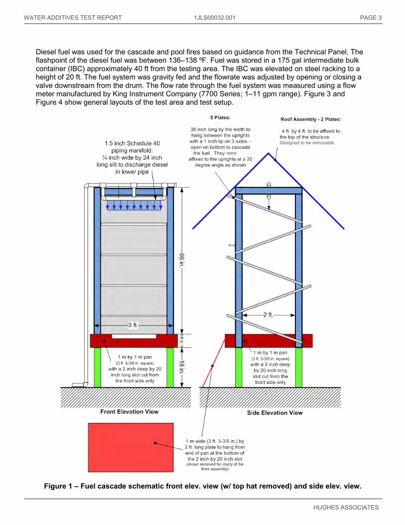
A relatively “standard” cascade array used in other similar tests was used as the three-dimensional Class B fire. It consisted of five inclined trays mounted above a 3.25 ft square pan. The fuel was discharged onto the top tray and flowed down that tray to the tray below which was inclined in the opposite direction. Fuel was discharged through a two pipe manifold; the top most pipe was connected to the fuel supply at one end and to the bottom pipe by three vertical pipes, one at the center and one near each end. The three connections were intended to balance the flow to the bottom pipe. A slit in the bottom pipe allowed the fuel to flow evenly onto the tray below; the slit was 0.25 in. wide and 2.0 ft long. The fuel flowed successively down each of the inclined trays prior to reaching the bottom pan. The bottom pan had a notch cut in the front of the pan to facilitate the flow of the fuel to a larger containment pan. In past test series, this apparatus had been used with fuel flows ranging from 2.5 to 12 gpm with the containment pan sized to prevent an excess buildup of fuel. For this test series a fuel flow rate of 2 gpm was used; this value was selected to be challenging but manageable flowrate. At this relatively low flowrate, the fuel tended to exit the slit on half of pipe which was nearest to the supply. This was deemed to be adequate as the fuel spread to cover the majority of the cascade trays below. A photograph of the fuel cascade is shown in Figure 1, with a detailed schematic shown in Figure 2. In this report, the fuel cascade is referred to as the 3D fire scenario.
The bottom pan of the fuel cascade was initially filled with 1.0 in. of water and 1 gal of diesel, with 0.05 gal of heptane as an accelerant. After Test 4, the amount of diesel was changed to 1.2 gal.
The cascade apparatus was centered within a containment pan 7.07 ft on a side. The containment pan was filled with fuel floated on water to create a two-dimensional fire, when required. When used with the fuel cascade, a fuel layer of 1.0 in. on top of 3.0 in. of water was used in the containment pan. When only the three-dimensional fuel cascade was used, the containment pan was filled with 2 in. of water. The “top hat” (roof) of the cascade was constructed but was not used in this testing. This obstruction makes the extinguishment of the 3D fire more difficult. When the 3D flowing fuel fire was not used, the apparatus was removed from the containment pan.
WATER ADDITIVES TEST REPORT 1JLS00032.001 PAGE 3
HUGHES ASSOCIATES
Diesel fuel was used for the cascade and pool fires based on guidance from the Technical Panel. The flashpoint of the diesel fuel was between 136–138 ºF. Fuel was stored in a 175 gal intermediate bulk container (IBC) approximately 40 ft from the testing area. The IBC was elevated on steel racking to a height of 20 ft. The fuel system was gravity fed and the flowrate was adjusted by opening or closing a valve downstream from the drum. The flow rate through the fuel system was measured using a flow meter manufactured by King Instrument Company (7700 Series; 1–11 gpm range). Figure 3 and Figure 4 show general layouts of the test area and test setup.
Figure 1 – Fuel cascade schematic front elev. view (w/ top hat removed) and side elev. view.
were
Designed to be removable.

WATER ADDITIVES TEST REPORT 1JLS00032.001 PAGE 4
HUGHES ASSOCIATES
Figure 2 – Fuel cascade.
Figure 3 – General layout of test area, plan view.
N
IBC, gravity fed through
flowmeter to achieve the 2
gpm diesel discharge rate
50 ft2 test pan, centered on room
Cascade in center of test pan
Steel Racking to Support Sprinkler Discharge Piping
(10 by 10 or 12 by 12 ft. spacings)
Nominal 2,000 gallon mixing tank for
holding the pre-mixed water additive
Pump and line to feed the sprinkler piping
Test Observation WindowFor Test Sponsors and Guests
100 ft. by 100 ft. moveable ceiling
(outline)
Diesel Supply Line
10 ft. 20 ft.
Near Radiometer
Far Radiometer
WATER ADDITIVES TEST REPORT 1JLS00032.001 PAGE 5
HUGHES ASSOCIATES
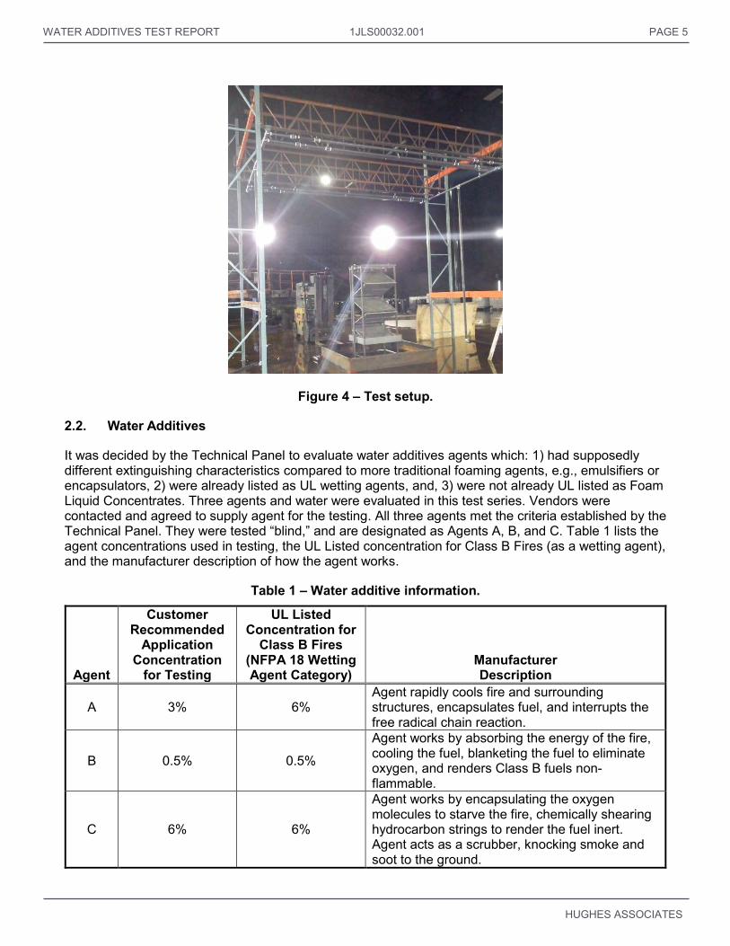
Figure 4 – Test setup.
2.2. Water Additives
It was decided by the Technical Panel to evaluate water additives agents which: 1) had supposedly different extinguishing characteristics compared to more traditional foaming agents, e.g., emulsifiers or encapsulators, 2) were already listed as UL wetting agents, and, 3) were not already UL listed as Foam Liquid Concentrates. Three agents and water were evaluated in this test series. Vendors were contacted and agreed to supply agent for the testing. All three agents met the criteria established by the Technical Panel. They were tested “blind,” and are designated as Agents A, B, and C. Table 1 lists the agent concentrations used in testing, the UL Listed concentration for Class B Fires (as a wetting agent), and the manufacturer description of how the agent works.
Table 1 – Water additive information.
Agent
Customer Recommended
Application Concentration
for Testing
UL Listed Concentration for
Class B Fires (NFPA 18 Wetting Agent Category)
Manufacturer Description
A 3% 6% Agent rapidly cools fire and surrounding structures, encapsulates fuel, and interrupts the free radical chain reaction.
B 0.5% 0.5%
Agent works by absorbing the energy of the fire, cooling the fuel, blanketing the fuel to eliminate oxygen, and renders Class B fuels non-flammable.
C 6% 6%
Agent works by encapsulating the oxygen molecules to starve the fire, chemically shearing hydrocarbon strings to render the fuel inert. Agent acts as a scrubber, knocking smoke and soot to the ground.

WATER ADDITIVES TEST REPORT 1JLS00032.001 PAGE 6
HUGHES ASSOCIATES
2.3. Water Additives System
A modified UL 162 sprinkler test was used for this test series (see Figure 4). The parameters were as follows:
Test pan – 50 ft2 (7.07 ft x 7.07 ft) Nozzle height – 15 ft to centerline of piping Sprinkler grid – 4 sprinklers located near the corners of the pan Cascade apparatus – centered in 50 ft2 test pan
The rationale for adopting this approach was: it provided a sprinkler test design as opposed to a water spray/optimized approach, more closely resembling an actual installation; and, it was readily available and used by the test lab (i.e., no pan or grid construction required).
Two different UL listed upright sprinklers were used in testing: Viking model VK300 (k=5.6) and Viking model VK350 (k=8.0). An initial sprinkler spacing of 10 ft x 10 ft was used which is associated with an ordinary hazard application rate of 0.30 gpm/ft2. The application rates used in testing are presented in Table 2 with the sprinkler spacing and k-factor. A schematic of the test layout including the sprinkler grid, test pan, and fuel cascade is shown in Figure 5. When the 12 ft x 12 ft spacing was used, the 10 ft x 10 ft sprinkler piping was left installed. Based on visual observations, the inclusion of this piping did not significantly affect the spray pattern of the sprinklers.
Table 2 – Application rate and sprinkler flow parameters.
Application Rate
(gpm/ft2)
Sprinkler Spacing
(ft)
k-factor of sprinkler
(gpm/psi1/2)
Approx. Nozzle
Pressure (psi)
Nominal flowrate of 4 sprinklers
(gpm) 0.16 12 5.6 17 92 0.22 12 8.0 16 128 0.30 10 8.0 14 120 0.45 10 8.0 32 180
The water plus additive was pumped from a 2,000 gallon reservoir using a gasoline powered fire pump. The liquid tank was approximately 70 in. in diameter and 13 ft tall. A recirculation loop was used to mix the water and additive into a premixed solution; a minimum mixing period of 5 minutes was used. This eliminated the need for real-time proportioning equipment. The liquid tank was filled with a maximum volume of 1,800 gallons. Each of the three agents was premixed at the concentration recommended by the manufacturer. The mass of water additive and water was measured to provide the correct ratio; the two components were added to the tank and thoroughly mixed using the recirculation pump for a minimum of 5 minutes. The mass of the water additive was calculated based on the known specific gravity and a measured volume of concentrate. The specific gravity was calculated using a known volume of liquid and measuring the mass on a Mettler Toledo model SG 8001 load cell (range: 17.8 lb; resolution: 0.0022 lb). The mass of the water in the tank was measured on a platform atop three load cells with ranges of 10,000 lb; the three load cells were BLH Electronics Type C3P1. A summing box was used to determine the total mass from the three load cells. The outlet of the tank was connected to the discharge piping. After an agent test series was completed, the tank was thoroughly rinsed with fresh water prior to preparing the next agent premix solution.
For tests with only water, the water was pumped from the main fire pumps at the UL test laboratory. For all tests, prior to setting up the 2D and/or 3D fire scenarios, the sprinkler system was set to the correct flow. The pump(s) were turned on and the water or water plus additive was flowed through the sprinkler system discharge piping. The flow was adjusted until the appropriate total flow rate for the test was

WATER ADDITIVES TEST REPORT 1JLS00032.001 PAGE 7
HUGHES ASSOCIATES
achieved. This process also ensured that when the pumps were turned on during the test, flow from the sprinklers would be immediate.
Figure 5 – Test layout schematic.
IR Camera
Digital Video Cameras
N

WATER ADDITIVES TEST REPORT 1JLS00032.001 PAGE 8
HUGHES ASSOCIATES
2.4. Instrumentation
Instrumentation included: flame height indicators, thermocouples, heat flux gauges, video cameras, and infrared cameras. Flame height was determined using video footage of the fire tests. A flame height indicator (ladder) was placed in the same plane as the centerline of the fuel pan, half way between the pan and the sprinkler piping support rack in order to calibrate video footage. Rungs on the indicator were 2.0 ft apart with the bottom most rung 9.75 ft above the floor (see Figure 6 and Figure 7).
Figure 6 – Flame height indicator (ladder).
Two Schmidt-Boelter heat flux gauges (50 kW/m2 range; Medtherm model 64-5SB-20) were placed outside of the 2D fuel pan to measure radiative heat flux from the fire. One heat flux gauge was positioned 10 ft from the side of the pan; this heat flux gauge was recessed 0.875 in inside of a 1.0 in. nominal diameter pipe as shown in Figure 8. This ensured that the measurement was not affected by liquid deposited on the surface of the gauge from the discharging sprinkler water. The effective viewing angle of this heat flux gauge was 39 degrees which subtended the 2D pan width at the 10 ft. spacing shown in Figure 5. The second heat flux gauge was positioned 20 ft from the side of the pan. This heat flux gauge was not recessed in a pipe because it was outside of the sprinkler spray pattern (see Figure 8); the viewing angle for this heat flux gauge was 180 degrees. Both heat flux gauges were centered approximately 5.0 ft above the floor. These measurements were used to compare the fires from test to test by assessing the degree of fire knockdown by the agents. The location of the radiometers is shown in Figure 5.
Flame Height Indicator (Ladder)

WATER ADDITIVES TEST REPORT 1JLS00032.001 PAGE 9
HUGHES ASSOCIATES
Figure 7 – Flame height indicator and instrumentation.
40 ft.
2 ft.
2 ft. (typical)
10 ft.
15 ft.
50 ft2
test pan
Cascade
Flame Height Indicator
(anchored chain link with
horizontal pipes, 2 ft. on
center)
Steel Beamwith embedded thermocouples
Elevation View from East Looking West
10 by 10 and 12 by 12 ft. spacing sprinkler system
(10 by 10 ft. spacing shown) 40 ft.
4 ft.
10 ft.
15 ft.
4 ft. long steel beam at ceiling
Elevation View from South Looking North
50 ft2
test pan
Cascade
10 by 10 and 12 by 12 ft. spacing sprinkler system
(10 by 10 ft. spacing shown)

WATER ADDITIVES TEST REPORT PAGE 10
HUGHES ASSOCIATES
Figure 8 – Photographs of recessed heat flux gauge (left) and exposed heat flux gauge (right).
Flowrate through the sprinkler discharge piping was measured using a Bailey/Fischer-Porter magnetic style flowmeter (Model Number 75EN140L2K) with a range of 0–500 gpm. This water flow device was placed downstream of the pump supply to assure the application rate of the desired sprinkler system was achieved.
Eight type-K thermocouples were used to measure the air temperature and temperature of a steel beam near the ceiling. The moveable ceiling was set to a height of 40 ft above the floor. The air thermocouples were located 6, 12, and 18 in. below the center of the ceiling above the fuel pan. Five thermocouples were embedded in a 4.0 ft long steel beam located as shown in Figure 7. All instrumentation data (i.e., flowrate, temperatures, heat flux) was recorded at a rate of 1 Hz.
Two digital video cameras and an infrared camera were placed at floor level on the side of the pan with the radiometers as shown in Figure 5. Four additional cameras were installed on the walls of the test space. These cameras were approximately 50 ft from the 2D pan and were used as backups for the floor cameras.
3.0 TEST PROCEDURES
Prior to each test, the sprinklers in the discharge array were checked; no replacement of sprinklers was necessary during the test series except to change between sprinklers with a different k-factor. The agent tank was then filled with water and additive.
Ventilation was initiated prior to ignition of the fuel. The ventilation rate was set such that visibility of the cascade apparatus was maintained. Prior to ignition, test data and video recording were initiated.
For the 2D only fire scenario, the ignition fuel in the pan was first ignited. Thirty seconds after full-involvement of the pan, the application of the water or water with additive was started. Full-involvement was determined by visual observation of the UL test director. This generally occurred 15 to 30 seconds after ignition. The sprinkler system flow was secured at the discretion of the UL test director. In general, the sprinkler system flow was secured after the fire was extinguished or a minimum five minute application period had been completed.
For the 3D only fire scenario, the ignition fuel in the cascade pan was first ignited. One minute after full-involvement of the pan, the fuel flow to the cascade was initiated and set to 2 gpm. Thirty seconds after full-involvement of the cascade, the application of the water with additive was started. Full-involvement was determined by visual observation of the UL test director. The sprinkler system and cascade fuel flows were secured at the discretion of the UL test director. In general, the sprinkler system flow was secured after the fire was extinguished or a minimum five minute application period had been completed.
For the 2D and 3D fire scenario, the ignition fuel in the cascade pan was first ignited. One minute after full-involvement of the cascade pan, the 2D pan was ignited and the fuel flow to the cascade was

WATER ADDITIVES TEST REPORT 1JLS00032.001 PAGE 11
HUGHES ASSOCIATES
initiated and set to 2 gpm. In general, forty-five seconds after full-involvement of the 2D pan, the application of the water with additive was started. For Test 17, the application of water began approximately 37 seconds after full-involvement. Full-involvement was determined by visual observation of the UL test director. The sprinkler system and cascade fuel flows were secured at the discretion of the UL test director. In general, the sprinkler system flow was secured after the fire was extinguished or a minimum five minute application period had been completed.
Prior to securing the water or water and additive system, an aqueous film-forming foam (AFFF) hand-line was used to extinguish residual flaming, when necessary. The duration of the agent application, time of extinguishment, or qualitatively, the extent to which the fire is suppressed were recorded. The containment pan and cascade were then emptied and cleaned in preparation for the next test.
4.0 RESULTS
4.1. Measures of Performance
In keeping with the philosophy established in the Phase I recommendations, performance in these tests was evaluated based on fire suppression and cooling. No attempt will be made to define the physio-chemical properties of any particular agent, such as encapsulation. Rather, the comparison was based on quantifiable fire-cooling, suppression, and extinguishment measures as follows:
Control Time (Visually Assessed)
2D – 90% of pan area extinguished 3D – (a) no trays burning, fire just in cascade pan; or, (b) if bottom cascade pan extinguished, fire on just one tray
2D and 3D – both the 2D and 3D criteria achieved
Figures 9 and 10 are representative photographs of the fully involved state (i.e., before agent application) and the 90% controlled state for each fire scenario, respectively.
Figure 9 – Representative photograph of fully involved 2D (left), 3D (center) and 2D+3D (right) fire scenarios.

WATER ADDITIVES TEST REPORT 1JLS00032.001 PAGE 12
HUGHES ASSOCIATES
Figure 10 – Representative photograph of 90% controlled 2D (left), 3D (center) and 2D+3D (right) fire scenarios.
Extinguishment Time (Visually Determined) Extinguishment time was the time between when the agent discharge began and:
2D – complete extinguishment of the 2D pan 3D – complete extinguishment of the 3D cascade, cascade pan, and any fire which may have spread to the 2D pan
2D and 3D – complete extinguishment of the 3D cascade, cascade pan, and 2D pan
Flame Height Flame height was determined using video footage from the East camera view (see Figure 7) which was facing the front of the fuel cascade. Flame height was calculated by measuring from the top of the pan to the tip of the flames in pixels using Bluebeam Revu software and scaling this based on the flame height indicator (see Section 2.4). Flame height was measured once every 5 seconds after ignition. For the 2D fires, ignition was defined as the ignition time of the 2D pan; for the 3D only and 2D+3D fires, ignition was defined as the ignition time of the cascade pan. Flame height is an important measure of performance because any steel structure exposed to direct flame impingement (i.e., directly above the fire) might fail in a short period of time. Plots of the flame height for each test are included in Appendix A.
A value of 90% reduction in flame height was calculated to determine when flames were reduced to an almost controlled state. For determination of the time to 90% reduction in flame height, the maximum value was calculated for each test. After the agent was turned on, the time at which the flame height fell below the percentage of the maximum was determined. Because flame heights tend to have large oscillations, two consecutive measurements of a 90% reduction were required to determine the flame height reduction time (which was the first of these measurements).
Heat Flux For all tests, the heat flux at the 20 ft distance was on the order of one third to one half of the heat flux at the 10 ft location. In general, the maximum heat fluxes recorded were nominally the same for the 2D fires and the 2D+3D fires, with the 3D fire scenario being lower. The averages of the peak heat fluxes for each fire scenario are shown in Table 3. Logically, one would expect that the addition of the 3D cascade to the 2D pan would produce a larger heat flux. It is possible that the 2D+3D scenario did not produce larger heat fluxes than the 2D pan alone because the 3D cascade blocked some of the re-radiation to the 2D pan, reducing its contribution. Plots of the heat flux for each test are included in Appendix B.
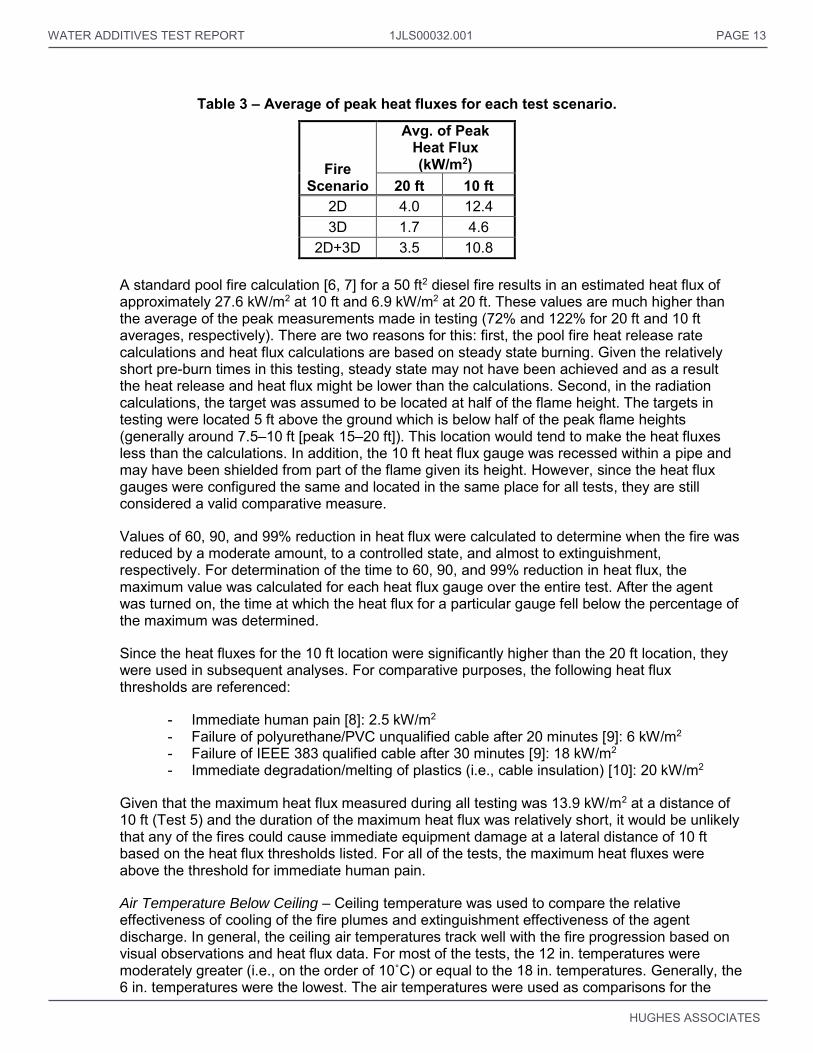
WATER ADDITIVES TEST REPORT 1JLS00032.001 PAGE 13
HUGHES ASSOCIATES
Table 3 – Average of peak heat fluxes for each test scenario.
Fire Scenario
Avg. of Peak Heat Flux (kW/m2)
20 ft 10 ft 2D 4.0 12.4 3D 1.7 4.6
2D+3D 3.5 10.8 A standard pool fire calculation [6, 7] for a 50 ft2 diesel fire results in an estimated heat flux of approximately 27.6 kW/m2 at 10 ft and 6.9 kW/m2 at 20 ft. These values are much higher than the average of the peak measurements made in testing (72% and 122% for 20 ft and 10 ft averages, respectively). There are two reasons for this: first, the pool fire heat release rate calculations and heat flux calculations are based on steady state burning. Given the relatively short pre-burn times in this testing, steady state may not have been achieved and as a result the heat release and heat flux might be lower than the calculations. Second, in the radiation calculations, the target was assumed to be located at half of the flame height. The targets in testing were located 5 ft above the ground which is below half of the peak flame heights (generally around 7.5–10 ft [peak 15–20 ft]). This location would tend to make the heat fluxes less than the calculations. In addition, the 10 ft heat flux gauge was recessed within a pipe and may have been shielded from part of the flame given its height. However, since the heat flux gauges were configured the same and located in the same place for all tests, they are still considered a valid comparative measure.
Values of 60, 90, and 99% reduction in heat flux were calculated to determine when the fire was reduced by a moderate amount, to a controlled state, and almost to extinguishment, respectively. For determination of the time to 60, 90, and 99% reduction in heat flux, the maximum value was calculated for each heat flux gauge over the entire test. After the agent was turned on, the time at which the heat flux for a particular gauge fell below the percentage of the maximum was determined.
Since the heat fluxes for the 10 ft location were significantly higher than the 20 ft location, they were used in subsequent analyses. For comparative purposes, the following heat flux thresholds are referenced:
- Immediate human pain [8]: 2.5 kW/m2 - Failure of polyurethane/PVC unqualified cable after 20 minutes [9]: 6 kW/m2 - Failure of IEEE 383 qualified cable after 30 minutes [9]: 18 kW/m2 - Immediate degradation/melting of plastics (i.e., cable insulation) [10]: 20 kW/m2
Given that the maximum heat flux measured during all testing was 13.9 kW/m2 at a distance of 10 ft (Test 5) and the duration of the maximum heat flux was relatively short, it would be unlikely that any of the fires could cause immediate equipment damage at a lateral distance of 10 ft based on the heat flux thresholds listed. For all of the tests, the maximum heat fluxes were above the threshold for immediate human pain.
Air Temperature Below Ceiling – Ceiling temperature was used to compare the relative effectiveness of cooling of the fire plumes and extinguishment effectiveness of the agent discharge. In general, the ceiling air temperatures track well with the fire progression based on visual observations and heat flux data. For most of the tests, the 12 in. temperatures were moderately greater (i.e., on the order of 10˚C) or equal to the 18 in. temperatures. Generally, the 6 in. temperatures were the lowest. The air temperatures were used as comparisons for the

WATER ADDITIVES TEST REPORT 1JLS00032.001 PAGE 14
HUGHES ASSOCIATES
other measures of performance. Plots of the air temperatures for each tests are included in Appendix C.
Values of 60, 90, and 99% reduction in air temperature were calculated to determine when the fire was reduced by a moderate amount, to a controlled state, and almost to extinguishment, respectively. For the determination of the time to 60, 90, and 99% reduction in temperature, the maximum temperature rise from ambient was calculated for each air thermocouple over the entire test. The ambient temperature was calculated as the average of the first three temperature measurements in the test data. After the agent was turned on, the time at which the particular air temperature fell below the percentage of the maximum above ambient plus the ambient value was determined.
Steel Beam Temperature – The steel beam temperatures did not track well with the fire development (see Figure 11); this was due to the thermal inertia of the beam and the relatively short test periods. The maximum recorded steel beam temperature was below 60˚C (Test 19). The beam temperature data for each test is included in Appendix D.
Figure 11 – Worst case plot of steel beam temperatures vs. time after ignition (Test 19).
4.2. Test Parameters
A total of 19 tests were conducted in this test series; four water only tests and five tests of each water additive were conducted. Table 4 is a test matrix of the tests conducted. The following testing approach was used for the water additives:
1. 2D fire alone, application rate of 0.30 gpm/ft2
2. 3D fire alone at application rate of 0.30 gpm/ft2
3. 2D+3D fire at application rate of 0.30 gpm/ft2
4. 2D fire alone, application rate of 0.16 gpm/ft2
5. 2D, 3D, or 2D+3D at application rate of 0.22 gpm/ft2 depending on prior results.
0
20
40
60
80
100
120
140
160
180
200
0 2 4 6 8 10
Tem
per
atu
re (
˚C)
Time (min)
Beam Temp 1Beam Temp 2Beam Temp 3Beam Temp 4Beam Temp 5

WATER ADDITIVES TEST REPORT 1JLS00032.001 PAGE 15
HUGHES ASSOCIATES
For the water only tests, only the 2D and 3D fires alone were conducted; application rates of 0.3 and 0.45 gpm/ft2 were used for each scenario.
In one test, Test 11, the flow rate through the sprinkler system was temporarily increased due to a faulty valve. For approximately the first 15 seconds of flow, the flow increased from approximately 92 gpm to 121 gpm and then decreased back down to approximately 92 gpm over the next 15 seconds and remained at this flow rate for the remainder of the test.
Table 4 – Test Matrix.
Test No. Date Agent
Test Scenario
Time of Day
(HH:MM)
Test Duration (MM:SS)
Agent Concentration
Sprinkler K-factor
(gpm/psi1/2)
Sprinkler Spacing
(ft)
Sprinkler Application
Rate (gpm/ft2)
Time from Ignition to Agent On
(sec)
Total Sprinkler flowrate (gpm)
1 5/27/14 Water 2D 13:12 8:32 - 8.0 10 0.3 45 120
2 5/27/14 Water 2D 14:52 5:10 - 8.0 10 0.45 45 180
3 5/28/14 A 2D 8:31 5:03 3% 8.0 10 0.3 60 120
4 5/28/14 A 3D 10:02 7:09 3% 8.0 10 0.3 113 120
5 5/28/14 A 2D + 3D 11:35 8:49 3% 8.0 10 0.3 120 120
6 5/28/14 A 2D 14:11 6:14 3% 5.6 12 0.16 70 92
7 5/28/14 A 2D 15:30 5:24 3% 8.0 12 0.22 60 128
8 5/29/14 B 2D 8:02 3:08 0.5% 8.0 10 0.3 60 120
9 5/29/14 B 3D 9:12 8:06 0.5% 8.0 10 0.3 120 120
10 5/29/14 B 2D+3D 10:25 8:56 0.5% 8.0 10 0.3 115 120
11 5/29/14 B 2D 12:58 3:57 0.5% 5.6 12 0.16 50 92A
12 5/29/14 B 2D+3D 14:21 11:22 0.5% 8.0 12 0.22 112 128
13 5/29/14 Water 3D 15:46 8:06 - 8.0 10 0.3 120 120
14 5/29/14 Water 3D 16:38 8:15 - 8.0 10 0.45 126 180
15 5/30/14 C 2D 8:38 2:01 6% 8.0 10 0.3 51 120
16 5/30/14 C 3D 9:13 8:13 6% 8.0 10 0.3 115 120
17 5/30/14 C 2D+3D 10:28 6:14 6% 8.0 10 0.3 115 120
18 5/30/14 C 2D 12:59 2:29 6% 5.6 12 0.16 60 92
19 5/30/14 C 3D 14:01 9:58 6% 8.0 12 0.22 115 128
A – Flow increase for first 30 seconds of flow.
4.3. Fire Suppression and Cooling Performance
The results of the fire tests are summarized in Tables 5, 6 and 7 for the 2D, 3D, and 2D+3D fire scenarios, respectively. The next three sections summarize these results for each fire scenario.
4.3.1. 2D Fires
The results of the 2D fire tests are summarized in Table 5. All three agents and water were tested with the 2D pan fire at an application rate of 0.3 gpm/ft2. All three agents were able to extinguish the fire at this application rate, with water only able to achieve 90% control after an extended discharge period. Based on the data in Table 5, the agents, from quickest to slowest in terms of knocking down the fire, were consistently Agent C, Agent B, Agent A, and Water. All three agents were significantly quicker than water at controlling the fire and reducing flame height and heat flux by 90%. For 90% control, Agent A was approximately 3 times quicker and Agent C was 21 times quicker than water. For time to 90% reduction in heat flux, all three agents were approximately 3 times quicker than water.
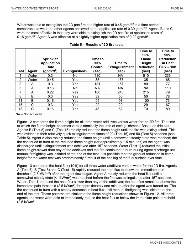
WATER ADDITIVES TEST REPORT 1JLS00032.001 PAGE 16
HUGHES ASSOCIATES
Water was able to extinguish the 2D pan fire at a higher rate of 0.45 gpm/ft2 in a time period comparable to what the other agents achieved at the application rate of 0.30 gpm/ft2. Agents B and C were the most effective in that they were able to extinguish the 2D pan fire at application rates of 0.16 gpm/ft2. Agent A was effective at a slightly higher application rate of 0.22 gpm/ft2.
Table 5 – Results of 2D fire tests.
Test Agent
Sprinkler Application
Rate (gpm/ft2) Extinguished?
Time to 90%
Control (sec)
Time to Extinguishment
(sec)
Time to 90%
Flame Height
Reduction (sec)
Time to 90%
Reduction in Heat
Flux – 10ft (sec)
1 Water 0.3 No 480 NA 510 236 2 Water 0.45 Yes 85 153 35 68 3 A 0.3 Yes 131 157 80 77 6 A 0.16 No NA NA NA 110 7 A 0.22 Yes 180 243 215 79 8 B 0.3 Yes 39 50 50 78
11 B 0.16 Yes 95 98 100 73 15 C 0.3 Yes 22 29 29 67 18 C 0.16 Yes 43 62 70 89
NA – Not achieved
Figure 12 compares the flame height for all three water additives versus water for the 2D fire. The time at which the flame height becomes zero is nominally the time of extinguishment. Based on this plot, Agents B (Test 8) and C (Test 15) rapidly reduced the flame height until the fire was extinguished. This was evident in their relatively quick extinguishment times of 29 (Test 15) and 50 (Test 8) seconds (see Table 5). Agent A also rapidly reduced the flame height until a somewhat steady state was reached; the fire continued to burn at the reduced flame height (for approximately 1.5 minutes) as the agent was discharged until extinguishment was achieved after 157 seconds. Water (Test 1) reduced the initial flame height slower than any of the additives and the fire continued to burn during agent discharge until manual firefighting was initiated at the end of the test. It is possible that the gradual reduction in flame height for the water test was predominantly a result of the cooling of the fuel surface over time.
Figure 13 compares the heat flux (10 ft) for all three water additives versus water for the 2D fire. Agents A (Test 3), B (Test 8) and C (Test 15) rapidly reduced the heat flux to below the immediate pain threshold (2.5 kW/m2) after the agent flow began. Agent A rapidly reduced the heat flux until a somewhat steady state (< 1kW/m2) was reached before the fire was extinguished after 157 seconds. Water (Test 1) reduced the heat flux slower than any of the additives; the heat flux remained above the immediate pain threshold (2.5 kW/m2) for approximately one minute after the agent was turned on. The fire continued to burn with a steady decrease in heat flux until manual firefighting was initiated at the end of the test. These patterns are similar to the flame height reductions shown in Figure 12. All three agents and water were able to immediately reduce the heat flux to below the immediate pain threshold (2.5 kW/m2).
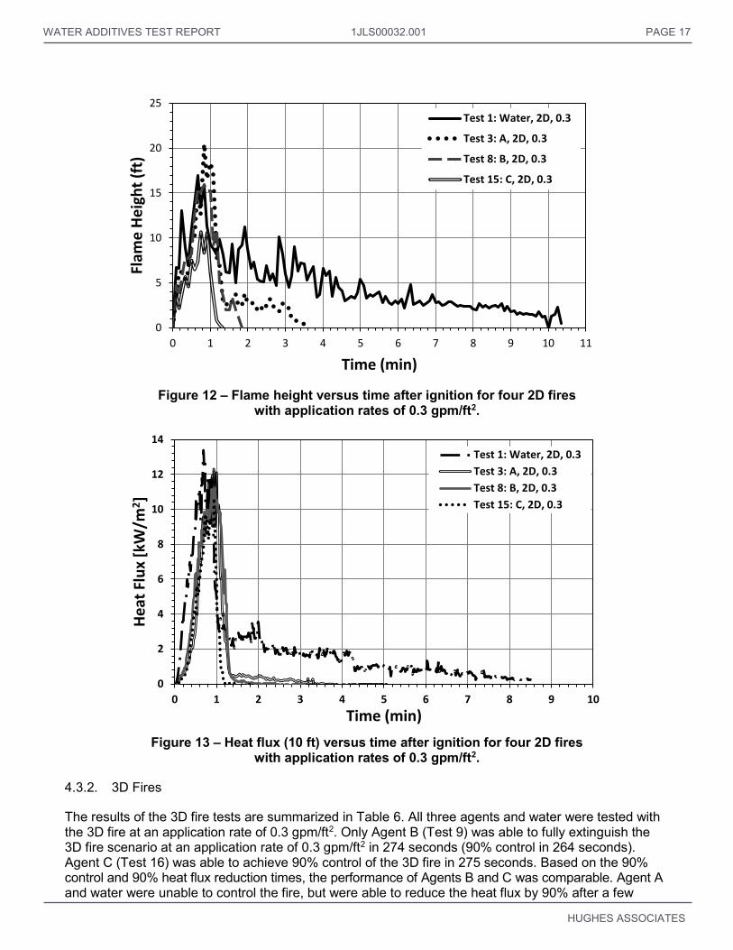
WATER ADDITIVES TEST REPORT 1JLS00032.001 PAGE 17
HUGHES ASSOCIATES
Figure 12 – Flame height versus time after ignition for four 2D fires
with application rates of 0.3 gpm/ft2.
Figure 13 – Heat flux (10 ft) versus time after ignition for four 2D fires
with application rates of 0.3 gpm/ft2.
4.3.2. 3D Fires
The results of the 3D fire tests are summarized in Table 6. All three agents and water were tested with the 3D fire at an application rate of 0.3 gpm/ft2. Only Agent B (Test 9) was able to fully extinguish the 3D fire scenario at an application rate of 0.3 gpm/ft2 in 274 seconds (90% control in 264 seconds). Agent C (Test 16) was able to achieve 90% control of the 3D fire in 275 seconds. Based on the 90% control and 90% heat flux reduction times, the performance of Agents B and C was comparable. Agent A and water were unable to control the fire, but were able to reduce the heat flux by 90% after a few
0
5
10
15
20
25
0 1 2 3 4 5 6 7 8 9 10 11
Flam
e H
eig
ht
(ft)
Time (min)
Test 1: Water, 2D, 0.3
Test 3: A, 2D, 0.3
Test 8: B, 2D, 0.3
Test 15: C, 2D, 0.3
0
2
4
6
8
10
12
14
0 1 2 3 4 5 6 7 8 9 10
He
at F
lux
[kW
/m2]
Time (min)
Test 1: Water, 2D, 0.3
Test 3: A, 2D, 0.3
Test 8: B, 2D, 0.3
Test 15: C, 2D, 0.3

WATER ADDITIVES TEST REPORT 1JLS00032.001 PAGE 18
HUGHES ASSOCIATES
minutes or more. Water was able to achieve a 90% reduction in heat flux in about half of the time than Agent A was.
Water was also tested at a higher application rate of 0.45 gpm/ft2. Even at this higher rate, water was unable to control the fire. The times to 90% reduction in heat flux for the two water tests at different rates were approximately equal. Agent C was the only additive to be tested twice; it was unable to extinguish or control the fire at the lower application rate (0.22 gpm/ft2). The times to 90% heat flux and flame height reduction were approximately twice as long for the 0.22 gpm/ft2 application rate versus the 0.3 gpm/ft2 application rate.
Table 6 – Results of 3D fire tests.
Test Agent
Sprinkler Application
Rate (gpm/ft2) Extinguished?
Time to 90%
Control (sec)
Time to Extinguishment
(sec)
Time to 90%
Flame Height
Reduction (sec)
Time to 90%
Reduction in Heat
Flux – 10ft (sec)
13 Water 0.3 No NA NA NA 155 14 Water 0.45 No NA NA 160 169 4 A 0.3 No NA1 NA NA 342 9 B 0.3 Yes 264 274 314 170 16 C 0.3 No 275 NA 150 167 19 C 0.22 No NA NA 365 367
NA – Not achieved 1 – 90% control was almost achieved at the end of the test
Figure 14 compares the flame heights for all three water additives versus water for the 3D fire scenario. Both Agents B and C steadily decreased the flame height after agent was applied until the fire was controlled or extinguished. Agent A decreased the flame height to about 30% of its maximum as quickly as the other agents, but the flames remained around 5.0 ft for the remainder of the test. Based on flame height reduction, all three agents had a marked improvement over water which did not significantly reduce the flame height over the duration of the test.
Figure 15 compares the heat flux (10 ft) of all three water additives versus water for the 3D fire scenario. None of the agent or water tests had peak heat fluxes higher than the long term cable damage threshold (6 kW/m2). Both agents B and C steadily decreased the heat flux after agent was applied until the fire was controlled or extinguished. Agent A (Test 4) decreased the heat flux to under 0.5 kW/m2 as quickly as the other agents despite not being able to achieve 90% control. Based on heat flux reduction, all three agents had a marked improvement over water. For water (Test 13), the heat flux was reduced approximately 50% initially and then to a steady state around 1 kW/m2 for the remainder of the test. All three agents and water were able to reduce the heat flux to below the immediate pain threshold (2.5 kW/m2) quickly after agent was discharged. The heat flux plots are similar to the flame height plots shown in Figure 14.

WATER ADDITIVES TEST REPORT 1JLS00032.001 PAGE 19
HUGHES ASSOCIATES
Figure 14 – Flame height versus time after ignition for four 3D fires with application rates of 0.3 gpm/ft2.
Figure 15 – Heat flux versus time after ignition for four 3D fires
with application rates of 0.3 gpm/ft2.
4.3.3. Combined 2D and 3D Fires
The results of the combined 2D and 3D fire tests are summarized in Table 7. Only the three water additives were tested with the 2D+3D fire scenario; water was not tested with this fire scenario as it had
0
5
10
15
20
25
0 1 2 3 4 5 6 7 8 9 10 11
Flam
e H
eig
ht
(ft)
Time (min)
Test 4: A, 3D, 0.3
Test 9: B, 3D, 0.3
Test 13: Water, 3D, 0.3
Test 16: C, 3D, 0.3
0
1
2
3
4
5
6
0 2 4 6 8 10
He
at F
lux
[kW
/m2]
Time (min)
Test 4: A, 3D, 0.3
Test 9: B, 3D, 0.3
Test 13: Water, 3D, 0.3
Test 16: C, 3D, 0.3

WATER ADDITIVES TEST REPORT 1JLS00032.001 PAGE 20
HUGHES ASSOCIATES
not been successful in either the 2D or 3D fire scenarios at an application rate of 0.3 gpm/ft2. All agents were tested at an application rate of 0.3 gpm/ft2. Both Agents B (Test 9) and C (Test 17) were able to fully extinguish the 2D+3D fire scenario at an application rate of 0.3 gpm/ft2; Agent A was unable to control the fire. Agent C was able to extinguish and control this fire scenario approximately 2 minutes faster than Agent B. Based on the 90% flame height and heat flux reduction times, the performance of Agent B was moderately better than Agent C. Test 17 appears to be an anomaly for Agent C given that this agent was unable to extinguish the 3D fire scenario (Test 16).
Agent B was also tested at a lower application rate of 0.22 gpm/ft2. Agent B was unable to extinguish or control the fire at this lower application rate. The time to 90% flame height reduction was approximately 6 times longer for the 0.22 gpm/ft2 application rate versus the 0.3 gpm/ft2 application rate; the times to 90% heat flux reduction were approximately equal.
Table 7 – Results of 2D+3D fire tests.
Test Agent
Sprinkler Application
Rate (gpm/ft2) Extinguished?
Time to 90%
Control (sec)
Time to Extinguishment
(sec)
Time to 90%
Flame Height
Reduction (sec)
Time to 90%
Reduction in Heat
Flux – 10ft (sec)
5 A 0.3 No NA NA NA 249 10 B 0.3 Yes 320 329 70 184 12 B 0.22 No NA NA 458 200 17 C 0.3 Yes 185 197 205 196
NA – not achieved Figure 16 compares the flame height for all three water additives for the 2D+3D fire scenario; Agents B (Test 10) and C (Test 17) were successful in extinguishing this scenario. Agent A (Test 5) produced a moderate reduction in flame height for this test scenario, but was unable to extinguish or control the fire. Based on extinguishing times, Agent C (197 sec) would appear to have performed better than Agent B (329 sec). For flame height reduction, Agent B reduced the flames to below 3.0 ft for approximately 4.5 minutes before extinguishment while for Agent C flaming was reduced to below 3.0 ft only a few seconds before extinguishment. This reinforces the usefulness of the flame height comparisons.
Figure 17 compares the heat flux (10 ft) for all three water additives for the 2D+3D fire scenario. All agents quickly reduced the heat flux to below the immediate pain threshold (2.5 kW/m2), with Agent A (Test 5) reaching a steady state value for the remainder of the test. Whereas in Figure 16 there were notable differences in the flame heights between Agent B (Test 10) and C (Test 17) after the initial reduction, the heat fluxes measured for these two tests were nominally the same after the initial reductions with the exception that the heat flux for Agent C went to zero (i.e., extinguishment) prior to Agent B.

WATER ADDITIVES TEST REPORT 1JLS00032.001 PAGE 21
HUGHES ASSOCIATES
Figure 16 – Flame height versus time after ignition for four 2D+3D fires
with application rates of 0.3 gpm/ft2. Note: water not tested for this fire scenario.
Figure 17 – Heat Flux versus time after ignition for four 2D+3D fires
with application rates of 0.3 gpm/ft2.
0
5
10
15
20
25
0 1 2 3 4 5 6 7 8 9 10 11
Flam
e H
eig
ht
(ft)
Time (min)
Test 5: A, 2D+3D, 0.3
Test 10: B, 2D+3D, 0.3
Test 17: C, 2D+3D, 0.3
0
2
4
6
8
10
12
14
0 2 4 6 8 10
He
at F
lux
[kW
/m2]
Time (min)
Test 5: A, 2D+3D, 0.3
Test 10: B, 2D+3D, 0.3
Test 17: C, 2D+3D, 0.3

WATER ADDITIVES TEST REPORT 1JLS00032.001 PAGE 22
HUGHES ASSOCIATES
5.0 DISCUSSION
5.1. Additional Analysis
At the application rates tested, water was found only to be effective on the 2D pan fires. Water required the highest application rate of 0.45 gpm/ft2 for extinguishment, although the test at 0.3 gpm/ft2 met the 90% control measure of performance. Given that the 2D pan fire was extinguished by water in under 3 minutes, it is possible that an application rate between 0.3 and 0.45 gpm/ft2 could have also caused complete extinguishment within a longer discharge period. However, such fine adjustment of the application rates was not within the scope of this test program.
Agent A extinguished the 2D pan fires at the application rates tested. Agent A was tested with the 2D pan at application rates of 0.3, 0.22, and 0.16 gpm/ft2; it extinguished the pan fires with the two higher application rates; it did not meet the 90% control measure of performance at the lowest application rate. Agent A was tested with the 3D and the 2D+3D at application rates of 0.3 gpm/ft2 without meeting the 90% control measure of performance, but was not tested at higher application rates due to time restrictions. Based on observations of the 3D and 2D+3D tests with Agent A, a higher application rate or, perhaps, a higher concentration, might contribute to improved performance. The 3% concentration was recommended for testing by the manufacturer; the UL wetting agent listing for Class B fires is 6%. Agent A produced a thin emulsification which floated atop the fuel layer after the test. An example of this is shown in Figure 18.
Figure 18 – Agent A emulsification after Test 3.
Agent B was the only water additive to successfully extinguish all three fire scenarios even though it had the lowest concentration (0.5% compared to 3% and 6% for agents A and C, respectively). Agent B successfully extinguished the 2D pan at the lowest application rate of 0.16 gpm/ft2 and the 3D and 2D+3D scenarios at an application rate of 0.3 gpm/ft2. Agent B was unsuccessful at extinguishing or controlling the 2D+3D scenario at an application rate of 0.22 gpm/ft2. Agent B produced a moderately thick (i.e., on the order of 0.5 in.) foam blanket which floated atop the fuel layer after the test; an example of this is shown in Figure 19.

WATER ADDITIVES TEST REPORT 1JLS00032.001 PAGE 23
HUGHES ASSOCIATES
Figure 19 – Agent B emulsification after Test 10.
Agent C successfully extinguished the 2D pan at the lowest application rate of 0.16 gpm/ft2 and the 2D+3D scenario at an application rate of 0.3 gpm/ft2. Despite successfully extinguishing the 2D+3D fire scenario, Agent C was unsuccessful at extinguishing the 3D scenario at application rates of 0.22 and 0.3 gpm/ft2 although it was able to meet the 90% control measure of performance with the higher application rate. It is unclear what may have caused this as the 3D fire would be considered easier to extinguish than the 2D+3D fires combined. The 3D cascade is an inherently difficult fire to suppress due to its many shielded surfaces. Agent C produced a rather thick (i.e., on the order of 4.0 in.) layer of bubbly film which blanketed the fuel layer after the test; an example of this is shown in Figure 20.
Figure 20 – Agent C bubbly layer after Test 17.
Table 8 lists the lowest application rate for each agent and fire scenario combinations where extinguishment occurred; tests where 90% control was achieved at a lower application rate but where extinguishment did not occur are also noted. For combinations where the agent did not extinguish the fire, the highest application rate tested for that combination is presented in parentheses. This

WATER ADDITIVES TEST REPORT 1JLS00032.001 PAGE 24
HUGHES ASSOCIATES
comparison does not consider the time element of the tests, i.e., how quickly the fires were extinguished. Based on the results in Table 8, all of the water additives improved on the performance of water for the 2D only fire scenario. Not only did all of the water additives require a smaller (less than half) application rate to extinguish the 2D fire, Agents B and C extinguished the fires in half of the time or less than water and with the lower application rates (see Table 5). Because water was unable to extinguish the 3D fire scenario at the application rates tested, there is no direct comparison between the extinguishment effectiveness of water versus Agents A or C. However, Agents B and C did improve on the performance of water for the 3D only fire scenario by extinguishing and controlling the fire, respectively, when water could not.
Table 8 – Extinguishment Comparison.
Agent Agent
Concentration
Lowest Application Rate with Extinguishment
(gpm/ft2) 2D 3D 2D+3D
Water - 0.45 A DNE (0.45) NT
A 3% 0.22 DNE (0.3)
DNE (0.3)
B 0.5% 0.16 0.3 0.3
C 6% 0.16 DNE (0.3)A 0.3
DNE – Did not extinguish (highest application rate tested in parentheses). NT – Not tested. A – Test at 0.3 gpm/ft2 achieved 90% control.
5.2. Threat Analysis
Additional measures of performance are presented here for comparative purposes. Table 9 shows the visual 90% reduction times and the times after agent is turned on until the heat flux or temperature is reduced to below 60, 90, or 99% of the maximum value. The 90% flame height reduction is also included. The methods for determining the reduction times are included in Section 4.1. None of the temperature measurements ever reached 99% reduction while almost all of the heat flux measurements did. In general, the heat flux reduction times were very close for the two gauges at 60% and 90%, but had wider ranges for the 99% reduction. For the air temperatures, the reduction times were close for the three thermocouples at 60% reduction but typically had more variation at 90% reduction.
For Table 9, the heat flux reduction times are shaded depending on whether the heat flux at that time was below the threshold value for immediate pain (2.5 kW/m2) or long term cable damage (6.0 kW/m2). For all of the 90 and 99% reduction times and the 60% reduction times for the 20 ft heat flux gauge, the heat flux at this time was below the pain threshold. For only 6 of 19 tests, based on the 10 ft heat flux gauge, at the 60% reduction times the heat flux was below the pain threshold.
Comparing the times to 90% reduction from the maximum heat flux and temperatures to the time to 90% controlled based on visual measurements provides mixed results (Table 9). In general, the times to 90% reduction in heat flux are much lower than the times to 90% control. On the other hand, the times to 90% reduction in temperature (e.g., for the 18 in. air temperature) are much closer and in some cases lower than the times to 90% control. This is possibly due to the fact that measurement of heat flux does not lag very much with the fire development and control while temperature does.

WATER ADDITIVES TEST REPORT 1JLS00032.001 PAGE 25
HUGHES ASSOCIATES
Table 9 – Summary of times after agent was turned on to % reduction in heat flux and air temperature.
Test Agent
Sprinkler Application
Rate (gpm/ft2)
Test Scenario
Time to 90%
Control – Visual (sec)
Time to 60% reduction (seconds)
Time to 90% reduction (seconds)
Time to 99% reduction (seconds)
6 in. Air TC
12 in. Air TC
18 in. Air TC
20ft Heat Flux
Gauge
10 ft Heat Flux
Gauge
6 in. Air TC
12 in. Air TC
18 in. Air TC
20ft Heat Flux
Gauge
10 ft Heat Flux
Gauge
Flame Height
6 in. Air TC
12 in. Air TC
18 in. Air TC
20ft Heat Flux
Gauge
10 ft Heat Flux
Gauge
1 Water 0.3 2D 480 34 42 40 14 14 449 439 428 137 191 510 NA NA NA NA NA
2 Water 0.45 2D 85 37 34 34 16 16 154 162 144 24 23 35 NA NA NA 63 59
3 A 0.3 2D 131 21 28 24 8 8 56 70 60 17 17 80 NA NA NA 19 122
4 A 0.3 3D NA 30 30 30 11 8 89 87 77 37 42 NA NA NA NA 114 150
5 A 0.3 2D + 3D NA 48 48 46 25 23 NA NA NA 139 129 NA NA NA NA NA NA
6 A 0.16 2D NA 47 45 45 13 11 NA NA NA 39 40 NA NA NA NA NA NA
7 A 0.22 2D 180 33 33 33 10 10 189 174 168 16 19 215 NA NA NA 96 123
8 B 0.3 2D 39 29 33 31 14 15 NA NA NA 18 18 50 NA NA NA 21 36
9 B 0.3 3D 264 31 35 35 10 8 111 111 111 44 49 160 NA NA NA 57 95
10 B 0.3 2D+3D 320 40 44 42 27 15 213 128 124 66 69 70 NA NA NA 137 289
11 B 0.16 2D 95 36 34 33 15 14 NA 86 77 23 23 100 NA NA NA 64 63
12 B 0.22 2D+3D NA 59 70 66 43 42 204 173 173 83 88 458 NA NA NA 123 159
13 Water 0.3 3D NA NA 328 330 10 9 NA NA NA 174 222 NA NA NA NA 315 222
14 Water 0.45 3D NA 34 27 30 7 6 251 134 99 10 44 314 NA NA NA 79 108
15 C 0.3 2D 22 30 34 30 12 11 NA NA NA 16 16 29 NA NA NA 18 19
16 C 0.3 3D 275 38 35 38 10 10 101 101 101 49 52 150 NA NA NA 83 126
17 C 0.3 2D+3D 185 42 50 39 16 15 179 171 123 73 81 205 NA NA NA 111 194
18 C 0.16 2D 43 35 37 35 13 11 NA NA NA 29 29 70 NA NA NA 44 52
19 C 0.22 3D NA 298 269 272 11 11 NA NA NA 60 252 365 NA NA NA 278 292
NA – Not Achieved Below pain
threshold (2.5 kW/m2)
Below long term cable damage threshold (6 kW/m2)

WATER ADDITIVES TEST REPORT PAGE 26
HUGHES ASSOCIATES
The transport time of the smoke through the sprinkler spray (and the associated heat absorption of the spray) to the ceiling causes some lag for comparison of fire size/control to temperature data.
The times to 99% reduction from maximum heat flux may be more comparable to the 90% visual control times than the 90% reduction times (for heat flux and temperature). Of the 19 tests, ten tests achieved both 99% reduction from maximum heat flux and 90% visual control. With the exception of three tests (Tests 7, 9, and 16), all of the 99% heat flux reduction and 90% visual control times were within approximately 30 seconds of each other. One reason for this could be the radiation attenuation of the sprinkler spray. The percentage of visual control was essentially a rough visual measurement of the reduction in heat release from fully involved. At a fixed distance, heat flux from a fire is roughly proportional to the heat release [6]. This would suggest that the 90% heat flux reduction should be approximately equal to the 90% visual control. However, basic radiation calculations do not account for radiation attenuation from sprinkler sprays. This means that the actual heat flux measured should be lower than what is expected (i.e., 99% reduced vs. 90% reduced).
5.3. Test Scenario
The fire scenarios used in this test series were limited in size by the relatively short pre-burn time, low fuel flowrate, and lack of the top-hat. Overall, the fire threat could have been made more difficult by increasing the fuel flowrate, increasing pre-burn times, using a fuel source under pressure (i.e., spray fire), or including more obstructions. In addition, it was found that the dual pipe arrangement of the fuel supply for the 3D cascade was not necessary; the slit size was also found to be too large.
The sprinkler arrangement did not technically meet the criteria for NFPA 13 [11] with respect to sprinkler k-factor. According to NFPA 13, a k-factor of 5.6 is appropriate for application rates up to 0.22 gpm/ft2, a k-factor of 8.0 is appropriate for application rates between 0.22 and 0.34 gpm/ft2, and a k-factor of 11 would be appropriate for application rates greater than or equal to 0.34 gpm/ft2. In this test series, sprinklers with a k-factor of 8.0 were used for application rates of 0.45 gpm/ft2. Based on visual observations of the spray pattern of the sprinklers, this is not believed to have had a significant impact on results.
6.0 CONCLUSIONS
1. The test scenarios provided an acceptable means to compare water to water additives.
2. The 2D fire was extinguished by all agents. An application rate of 0.45 gpm/ft2 was required for water to achieve total extinguishment which is greater than the 0.25 gpm/ft2 baseline referenced in NFPA 850 for boiler front oil fires. Water additives were effective at application rates of 0.3 gpm/ft2 and lower.
a. NFPA 850 should consider increasing the minimum water application rate for protection of fuel oil hazards.
b. The use of these results for turbine lubricating oils hazards may not be appropriate, since higher flashpoint fluids were not tested. Also, these tests did not include unconfined spills or spray fires.
3. Water failed to extinguish the 3D and 2D+3D fire scenarios. Two of the three water additives extinguished fires which included the 3D scenario.
4. Generally, the water additives provided quicker reductions in the thermal threat of the fires compared to water.

WATER ADDITIVES TEST REPORT 1JLS00032.001 PAGE 27
HUGHES ASSOCIATES
5. From an overall performance standpoint, water additives were superior to plain water. However, the performance of water in the fire scenarios may be improved with longer test periods.
6. Performance differences were observed between the three water additives tested. This might be attributable to physio-chemical properties of a particular agent, or agent concentration. These factors were not evaluated. All water additives created a residual emulsification or foam layer which was evident at the conclusion of the test.
7. The fire scenarios used are not considered worst case, but do represent real-life conditions which might occur where there are Class B hazards. For comparative purposes, the scenarios demonstrated performance differences between water and water additives.
8. If the test apparatus and scenarios are considered for adoption for standards making/listing of water additives:
a. Minor modifications should be made to the setup, for example the 3D cascade pipe slit should be smaller, and the top pipe could be eliminated;
b. A maximum time to achieve the performance metric should be established. A range of performance metrics were analyzed: 90% visual control, extinguishment, and 60/90/99% thermal threat reductions. One or more of these could be used in a performance standard adopted for assessing water additives; and
c. Tests should be conducted with a greater floor-to-sprinkler height where installations having heights greater than 15 ft are anticipated. Alternately, an increased application rate than that established for 15 ft high performance could be used as a safety factor for any increased height installation.
7.0 ACKNOWLEDGEMENTS
The authors would like to thank the NFPA Research Foundation personnel and project Technical Panel for their assistance in guiding the test planning and advising the test group. The authors would like to also thank the water additive manufacturers for the donations of their agents for testing.
8.0 REFERENCES
1) Scheffey, J., Forssell, E., and Childs, J., “Evaluation of Water Additives for Fire Control and Vapor Mitigation,” Fire Protection Research Foundation, Quincy, MA, June 2013.
2) NFPA 18, Standard on Wetting Agents, National Fire protection Association, Quincy, MA, 2011.
3) NFPA 850, Recommended Practice for Fire Protection for Electric Generating Plants and High Voltage Direct Current Converter Stations, National Fire protection Association, Quincy, MA, 2010.
4) UL 162, Standard for Foam Equipment and Liquid Concentrates, Underwriters Laboratories, Northbrook, IL, 1999.
5) Scheffey, J. and Benfer, M., “Test Plan – Two and Three Dimensional Class B Fire Tests of Water Additives,” Hughes Associates Inc., Baltimore, MD, April 2014.
6) Beyler, C., “Fire Hazard Calculations for Large, Open Hydrocarbon Fires,” SFPE Handbook of Fire Protection Engineering, 4th Edition, DiNenno, P.J. (ed.), National Fire Protection Association, Quincy, MA, 2008, pp. 3.278–3.280.

WATER ADDITIVES TEST REPORT 1JLS00032.001 PAGE 28
HUGHES ASSOCIATES
7) Babrauskas, V., “Estimating Large Pool Fire Burning Rates,” Fire Technology, 19 (4), 1983.
8) Purser, D., “Assessment of Hazards to Occupants from Smoke, Toxic Gases, and Heat,” SFPE Handbook of Fire Protection Engineering, 4th Edition, DiNenno, P.J. (ed.), National Fire Protection Association, Quincy, MA, 2008, pp. 2.96–2.193.
9) Lukens, L.L., "Nuclear Power Plant Electrical Cable Damageability Experiments,” NUREG/CR-2927, SAND82-0926, Nuclear Regulatory Commission, Washington, D.C., October 1982.
10) Scheffey, J.L., Williams, F.W., Jonas, L.A., Byrd, R., and Toomey, T.A., "Analysis of Quick Response Fire Fighting Equipment for Submarines-Phase II, Large Scale Doctrine and Tactics Tests," NRL Memorandum Rpt 6632, Naval Research Laboratory, Washington, DC, July 10, 1990.
11) NFPA 13, “Standard for the Installation of Sprinkler Systems,” National Fire protection Association, Quincy, MA, 2013.

WATER ADDITIVES TEST REPORT PAGE 29
HUGHES ASSOCIATES
APPENDIX A – FLAME HEIGHT VS. TIME AFTER IGNITION

WATER ADDITIVES TEST REPORT PAGE 30
HUGHES ASSOCIATES
Figure A1 – Flame height vs. time after ignition for Test 1 (Water, 2D, 0.3 gpm/ft2).
Figure A2 – Flame height vs. time after ignition for Test 2 (Water, 2D, 0.45 gpm/ft2).
0
2
4
6
8
10
12
14
16
18
0 2 4 6 8 10 12
Flam
e H
eig
ht
(ft)
Time (min)
Test 1: Water, 2D, 0.3
Agent On
0
5
10
15
20
25
0 0.5 1 1.5 2 2.5 3 3.5 4
Flam
e H
eig
ht
(ft)
Time (min)
Test 2:Water, 2D, 0.45
Agent On

WATER ADDITIVES TEST REPORT 1JLS00032.001 PAGE 31
HUGHES ASSOCIATES
Figure A3 – Flame height vs. time after ignition for Test 3 (Agent A, 2D, 0.3 gpm/ft2).
Figure A4 – Flame height vs. time after ignition for Test 4 (Agent A, 3D, 0.3 gpm/ft2).
0
5
10
15
20
25
0 0.5 1 1.5 2 2.5 3 3.5 4
Flam
e H
eig
ht
(ft)
Time (min)
Test 3: A, 2D, 0.3
Agent On
0
5
10
15
20
25
0 1 2 3 4 5 6 7 8
Flam
e H
eig
ht
(ft)
Time (min)
Test 4: A, 3D, 0.3
Agent On

WATER ADDITIVES TEST REPORT 1JLS00032.001 PAGE 32
HUGHES ASSOCIATES
Figure A5 – Flame height vs. time after ignition for Test 5 (Agent A, 2D+3D, 0.3 gpm/ft2).
Figure A6 – Flame height vs. time after ignition for Test 6 (Agent A, 2D, 0.16 gpm/ft2).
0
5
10
15
20
25
0 2 4 6 8 10 12
Flam
e H
eig
ht
(ft)
Time (min)
Test 5: A, 2D+3D, 0.3
Agent On
0
2
4
6
8
10
12
14
16
18
0 1 2 3 4 5 6 7 8
Flam
e H
eig
ht
(ft)
Time (min)
Test 6: A, 2D, 0.16
Agent On

WATER ADDITIVES TEST REPORT 1JLS00032.001 PAGE 33
HUGHES ASSOCIATES
Figure A7 – Flame height vs. time after ignition for Test 7 (Agent A, 2D, 0.22 gpm/ft2).
Figure A8 – Flame height vs. time after ignition for Test 8 (Agent B, 2D, 0.3 gpm/ft2).
0
5
10
15
20
25
0 1 2 3 4 5 6
Flam
e H
eig
ht
(ft)
Time (min)
Test 7: A, 2D, 0.22
Agent On
0
2
4
6
8
10
12
14
16
18
0 0.5 1 1.5 2
Flam
e H
eig
ht
(ft)
Time (min)
Test 8: B, 2D, 0.3
Agent On

WATER ADDITIVES TEST REPORT 1JLS00032.001 PAGE 34
HUGHES ASSOCIATES
Figure A9 – Flame height vs. time after ignition for Test 9 (Agent B, 3D, 0.3 gpm/ft2).
Figure A10 – Flame height vs. time after ignition for Test 10 (Agent B, 2D+3D, 0.3 gpm/ft2).
0
2
4
6
8
10
12
14
16
18
20
0 1 2 3 4 5 6 7
Flam
e H
eig
ht
(ft)
Time (min)
Test 9: B, 3D, 0.3
Agent On
0
2
4
6
8
10
12
14
16
18
0 2 4 6 8 10
Flam
e H
eig
ht
(ft)
Time (min)
Test 10: B, 2D+3D, 0.3
Agent On

WATER ADDITIVES TEST REPORT 1JLS00032.001 PAGE 35
HUGHES ASSOCIATES
Figure A11 – Flame height vs. time after ignition for Test 11 (Agent B, 2D, 0.16 gpm/ft2).
Figure A12 – Flame height vs. time after ignition for Test 12 (Agent B, 2D+3D, 0.22 gpm/ft2).
0
2
4
6
8
10
12
14
16
0 0.5 1 1.5 2 2.5 3
Flam
e H
eig
ht
(ft)
Time (min)
Test 11: B, 2D, 0.16
Agent On
0
5
10
15
20
25
0 2 4 6 8 10 12
Flam
e H
eig
ht
(ft)
Time (min)
Test 12: B, 2D+3D, 0.22
Agent On

WATER ADDITIVES TEST REPORT 1JLS00032.001 PAGE 36
HUGHES ASSOCIATES
Figure A13 – Flame height vs. time after ignition for Test 13 (Water, 3D, 0.3 gpm/ft2).
Figure A14 – Flame height vs. time after ignition for Test 14 (Water, 3D, 0.45 gpm/ft2).
0
5
10
15
20
25
0 1 2 3 4 5 6 7 8
Flam
e H
eig
ht
(ft)
Time (min)
Test 13: Water, 3D, 0.3
Agent On
0
2
4
6
8
10
12
14
16
0 2 4 6 8 10
Flam
e H
eig
ht
(ft)
Time (min)
Test 14: Water, 3D, 0.45
Agent On

WATER ADDITIVES TEST REPORT 1JLS00032.001 PAGE 37
HUGHES ASSOCIATES
Figure A15 – Flame height vs. time after ignition for Test 15 (Agent C, 2D, 0.3 gpm/ft2).
Figure A16 – Flame height vs. time after ignition for Test 16 (Agent C, 3D, 0.3 gpm/ft2).
0
2
4
6
8
10
12
14
16
0 0.2 0.4 0.6 0.8 1 1.2 1.4 1.6
Flam
e H
eig
ht
(ft)
Time (min)
Test 15: C, 2D, 0.3
Agent On
0
2
4
6
8
10
12
14
16
18
0 1 2 3 4 5 6 7 8
Flam
e H
eig
ht
(ft)
Time (min)
Test 16: C, 3D, 0.3
Agent On

WATER ADDITIVES TEST REPORT 1JLS00032.001 PAGE 38
HUGHES ASSOCIATES
Figure A17 – Flame height vs. time after ignition for Test 17 (Agent C, 2D+3D, 0.3 gpm/ft2).
Figure A18 – Flame height vs. time after ignition for Test 18 (Agent C, 2D, 0.16 gpm/ft2).
0
2
4
6
8
10
12
14
16
18
20
0 1 2 3 4 5 6
Flam
e H
eig
ht
(ft)
Time (min)
Test 17: C, 2D+3D, 0.3
Agent On
0
2
4
6
8
10
12
14
0 0.5 1 1.5 2 2.5
Flam
e H
eig
ht
(ft)
Time (min)
Test 18: C, 2D, 0.16
Agent On

WATER ADDITIVES TEST REPORT 1JLS00032.001 PAGE 39
HUGHES ASSOCIATES
Figure A19 – Flame height vs. time after ignition for Test 19 (Agent C, 3D, 0.22 gpm/ft2).
0
2
4
6
8
10
12
14
16
18
20
0 2 4 6 8 10
Flam
e H
eig
ht
(ft)
Time (min)
Test 19: C, 3D, 0.22
Agent On

WATER ADDITIVES TEST REPORT PAGE 40
HUGHES ASSOCIATES
APPENDIX B – HEAT FLUX VS. TIME AFTER IGNITION

WATER ADDITIVES TEST REPORT PAGE 41
HUGHES ASSOCIATES
Figure B1 – Heat flux vs. time after ignition for Test 1 (Water, 2D, 0.3 gpm/ft2).
0
2
4
6
8
10
12
14
16
18
20
0 2 4 6 8 10
Hea
t Fl
ux
[kW
/m2]
Time (min)
20 foot
10 foot
Agent On

WATER ADDITIVES TEST REPORT 1JLS00032.001 PAGE 42
HUGHES ASSOCIATES
Figure B2 – Heat flux vs. time after ignition for Test 2 (Water, 2D, 0.45 gpm/ft2).
0
2
4
6
8
10
12
14
16
18
20
0 2 4 6 8 10
Hea
t Fl
ux
[kW
/m2]
Time (min)
20 foot
10 foot
Agent On

WATER ADDITIVES TEST REPORT 1JLS00032.001 PAGE 43
HUGHES ASSOCIATES
Figure B3 – Heat flux vs. time after ignition for Test 3 (Agent A, 2D, 0.3 gpm/ft2).
0
2
4
6
8
10
12
14
16
18
20
0 2 4 6 8 10
Hea
t Fl
ux
[kW
/m2]
Time (min)
20 foot10 footAgent On

WATER ADDITIVES TEST REPORT 1JLS00032.001 PAGE 44
HUGHES ASSOCIATES
Figure B4 – Heat flux vs. time after ignition for Test 4 (Agent A, 3D, 0.3 gpm/ft2).
0
2
4
6
8
10
12
14
16
18
20
0 2 4 6 8 10
Hea
t Fl
ux
[kW
/m2]
Time (min)
20 foot
10 foot
Agent On

WATER ADDITIVES TEST REPORT 1JLS00032.001 PAGE 45
HUGHES ASSOCIATES
Figure B5 – Heat flux vs. time after ignition for Test 5 (Agent A, 2D+3D, 0.3 gpm/ft2).
0
2
4
6
8
10
12
14
16
18
20
0 2 4 6 8 10
Hea
t Fl
ux
[kW
/m2]
Time (min)
20 foot
10 foot
Agent On

WATER ADDITIVES TEST REPORT 1JLS00032.001 PAGE 46
HUGHES ASSOCIATES
Figure B6 – Heat flux vs. time after ignition for Test 6 (Agent A, 2D, 0.16 gpm/ft2).
0
2
4
6
8
10
12
14
16
18
20
0 2 4 6 8 10
Hea
t Fl
ux
[kW
/m2]
Time (min)
20 foot
10 foot
Agent On

WATER ADDITIVES TEST REPORT 1JLS00032.001 PAGE 47
HUGHES ASSOCIATES
Figure B7 – Heat flux vs. time after ignition for Test 7 (Agent A, 2D, 0.22 gpm/ft2).
0
2
4
6
8
10
12
14
16
18
20
0 2 4 6 8 10
Hea
t Fl
ux
[kW
/m2]
Time (min)
20 foot
10 foot
Agent On
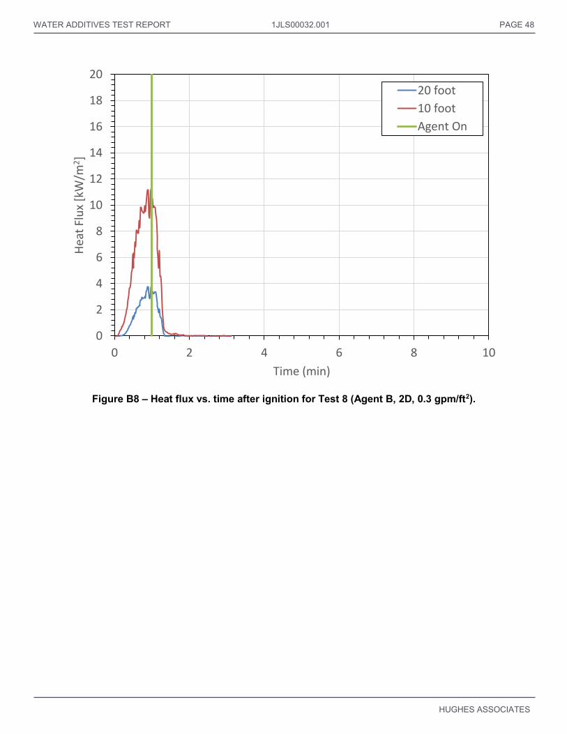
WATER ADDITIVES TEST REPORT 1JLS00032.001 PAGE 48
HUGHES ASSOCIATES
Figure B8 – Heat flux vs. time after ignition for Test 8 (Agent B, 2D, 0.3 gpm/ft2).
0
2
4
6
8
10
12
14
16
18
20
0 2 4 6 8 10
Hea
t Fl
ux
[kW
/m2]
Time (min)
20 foot
10 foot
Agent On

WATER ADDITIVES TEST REPORT 1JLS00032.001 PAGE 49
HUGHES ASSOCIATES
Figure B9 – Heat flux vs. time after ignition for Test 9 (Agent B, 3D, 0.3 gpm/ft2).
0
2
4
6
8
10
12
14
16
18
20
0 2 4 6 8 10
Hea
t Fl
ux
[kW
/m2]
Time (min)
20 foot
10 foot
Agent On

WATER ADDITIVES TEST REPORT 1JLS00032.001 PAGE 50
HUGHES ASSOCIATES
Figure B10 – Heat flux vs. time after ignition for Test 10 (Agent B, 2D+3D, 0.3 gpm/ft2).
0
2
4
6
8
10
12
14
16
18
20
0 2 4 6 8 10
Hea
t Fl
ux
[kW
/m2]
Time (min)
20 foot10 footAgent On

WATER ADDITIVES TEST REPORT 1JLS00032.001 PAGE 51
HUGHES ASSOCIATES
Figure B11 – Heat flux vs. time after ignition for Test 11 (Agent B, 2D, 0.16 gpm/ft2).
0
2
4
6
8
10
12
14
16
18
20
0 2 4 6 8 10
Hea
t Fl
ux
[kW
/m2]
Time (min)
20 foot10 footAgent On

WATER ADDITIVES TEST REPORT 1JLS00032.001 PAGE 52
HUGHES ASSOCIATES
Figure B12 – Heat flux vs. time after ignition for Test 12 (Agent B, 2D+3D, 0.22 gpm/ft2).
0
2
4
6
8
10
12
14
16
18
20
0 2 4 6 8 10
Hea
t Fl
ux
[kW
/m2]
Time (min)
20 foot10 footAgent On

WATER ADDITIVES TEST REPORT 1JLS00032.001 PAGE 53
HUGHES ASSOCIATES
Figure B13 – Heat flux vs. time after ignition for Test 13 (Water, 3D, 0.3 gpm/ft2).
0
2
4
6
8
10
12
14
16
18
20
0 2 4 6 8 10
Hea
t Fl
ux
[kW
/m2]
Time (min)
20 foot10 footAgent On

WATER ADDITIVES TEST REPORT 1JLS00032.001 PAGE 54
HUGHES ASSOCIATES
Figure B14 – Heat flux vs. time after ignition for Test 14 (Water, 3D, 0.45 gpm/ft2).
0
2
4
6
8
10
12
14
16
18
20
0 2 4 6 8 10
Hea
t Fl
ux
[kW
/m2]
Time (min)
20 foot
10 foot
Agent On

WATER ADDITIVES TEST REPORT 1JLS00032.001 PAGE 55
HUGHES ASSOCIATES
Figure B15 – Heat flux vs. time after ignition for Test 15 (Agent C, 2D, 0.3 gpm/ft2).
0
2
4
6
8
10
12
14
16
18
20
0 2 4 6 8 10
Hea
t Fl
ux
[kW
/m2]
Time (min)
20 foot
10 foot
Agent On

WATER ADDITIVES TEST REPORT 1JLS00032.001 PAGE 56
HUGHES ASSOCIATES
Figure B16 – Heat flux vs. time after ignition for Test 16 (Agent C, 3D, 0.3 gpm/ft2).
0
2
4
6
8
10
12
14
16
18
20
0 2 4 6 8 10
Hea
t Fl
ux
[kW
/m2]
Time (min)
20 foot
10 foot
Agent On

WATER ADDITIVES TEST REPORT 1JLS00032.001 PAGE 57
HUGHES ASSOCIATES
Figure B17 – Heat flux vs. time after ignition for Test 17 (Agent C, 2D+3D, 0.3 gpm/ft2).
0
2
4
6
8
10
12
14
16
18
20
0 2 4 6 8 10
Hea
t Fl
ux
[kW
/m2]
Time (min)
20 foot10 footAgent On

WATER ADDITIVES TEST REPORT 1JLS00032.001 PAGE 58
HUGHES ASSOCIATES
Figure B18 – Heat flux vs. time after ignition for Test 18 (Agent C, 2D, 0.16 gpm/ft2).
0
2
4
6
8
10
12
14
16
18
20
0 2 4 6 8 10
Hea
t Fl
ux
[kW
/m2]
Time (min)
20 foot
10 foot
Agent On
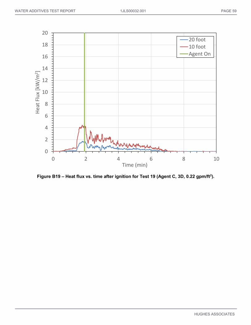
WATER ADDITIVES TEST REPORT 1JLS00032.001 PAGE 59
HUGHES ASSOCIATES
Figure B19 – Heat flux vs. time after ignition for Test 19 (Agent C, 3D, 0.22 gpm/ft2).
0
2
4
6
8
10
12
14
16
18
20
0 2 4 6 8 10
Hea
t Fl
ux
[kW
/m2]
Time (min)
20 foot10 footAgent On
WATER ADDITIVES TEST REPORT PAGE 60
HUGHES ASSOCIATES
APPENDIX C – CEILING AIR TEMPERATURES VS. TIME AFTER IGNITION

WATER ADDITIVES TEST REPORT PAGE 61
HUGHES ASSOCIATES
Figure C1 – Air temperatures vs. time after ignition for Test 1 (Water, 2D, 0.3 gpm/ft2).
0
20
40
60
80
100
120
140
160
180
200
0 2 4 6 8 10
Tem
pe
ratu
re (
de
g C
)
Time (min)
6 in.
12 in.
18 in.
Agent On

WATER ADDITIVES TEST REPORT 1JLS00032.001 PAGE 62
HUGHES ASSOCIATES
Figure C2 – Air temperatures vs. time after ignition for Test 2 (Water, 2D, 0.45 gpm/ft2).
0
20
40
60
80
100
120
140
160
180
200
0 2 4 6 8 10
Tem
per
atu
re (
deg
C)
Time (min)
6 in.
12 in.
18 in.
Agent On

WATER ADDITIVES TEST REPORT 1JLS00032.001 PAGE 63
HUGHES ASSOCIATES
Figure C3 – Air temperatures vs. time after ignition for Test 3 (Agent A, 2D, 0.3 gpm/ft2).
0
20
40
60
80
100
120
140
160
180
200
0 2 4 6 8 10
Tem
per
atu
re (
deg
C)
Time (min)
6 in.
12 in.
18 in.
Agent On
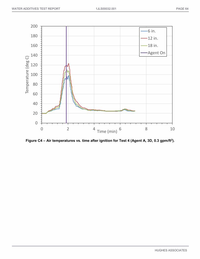
WATER ADDITIVES TEST REPORT 1JLS00032.001 PAGE 64
HUGHES ASSOCIATES
Figure C4 – Air temperatures vs. time after ignition for Test 4 (Agent A, 3D, 0.3 gpm/ft2).
0
20
40
60
80
100
120
140
160
180
200
0 2 4 6 8 10
Tem
per
atu
re (
deg
C)
Time (min)
6 in.
12 in.
18 in.
Agent On

WATER ADDITIVES TEST REPORT 1JLS00032.001 PAGE 65
HUGHES ASSOCIATES
Figure C5 – Air temperatures vs. time after ignition for Test 5 (Agent A, 2D+3D, 0.3 gpm/ft2).
0
20
40
60
80
100
120
140
160
180
200
0 2 4 6 8 10
Tem
per
atu
re (
deg
C)
Time (min)
6 in.
12 in.
18 in.
Agent On

WATER ADDITIVES TEST REPORT 1JLS00032.001 PAGE 66
HUGHES ASSOCIATES
Figure C6 – Air temperatures vs. time after ignition for Test 6 (Agent A, 2D, 0.16 gpm/ft2).
0
20
40
60
80
100
120
140
160
180
200
0 2 4 6 8 10
Tem
per
atu
re (
deg
C)
Time (min)
6 in.
12 in.
18 in.
Agent On
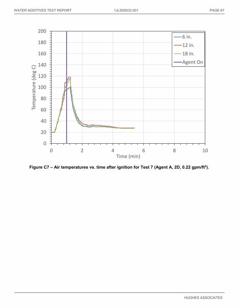
WATER ADDITIVES TEST REPORT 1JLS00032.001 PAGE 67
HUGHES ASSOCIATES
Figure C7 – Air temperatures vs. time after ignition for Test 7 (Agent A, 2D, 0.22 gpm/ft2).
0
20
40
60
80
100
120
140
160
180
200
0 2 4 6 8 10
Tem
per
atu
re (
deg
C)
Time (min)
6 in.
12 in.
18 in.
Agent On

WATER ADDITIVES TEST REPORT 1JLS00032.001 PAGE 68
HUGHES ASSOCIATES
Figure C8 – Air temperatures vs. time after ignition for Test 8 (Agent B, 2D, 0.3 gpm/ft2).
0
20
40
60
80
100
120
140
160
180
200
0 2 4 6 8 10
Tem
per
atu
re (
deg
C)
Time (min)
6 in.
12 in.
18 in.
Agent On

WATER ADDITIVES TEST REPORT 1JLS00032.001 PAGE 69
HUGHES ASSOCIATES
Figure C9 – Air temperatures vs. time after ignition for Test 9 (Agent B, 3D, 0.3 gpm/ft2).
0
20
40
60
80
100
120
140
160
180
200
0 2 4 6 8 10
Tem
per
atu
re (
deg
C)
Time (min)
6 in.
12 in.
18 in.
Agent On

WATER ADDITIVES TEST REPORT 1JLS00032.001 PAGE 70
HUGHES ASSOCIATES
Figure C10 – Air temperatures vs. time after ignition for Test 10 (Agent B, 2D+3D, 0.3 gpm/ft2).
0
20
40
60
80
100
120
140
160
180
200
0 2 4 6 8 10
Tem
per
atu
re (
deg
C)
Time (min)
6 in.
12 in.
18 in.
Agent On
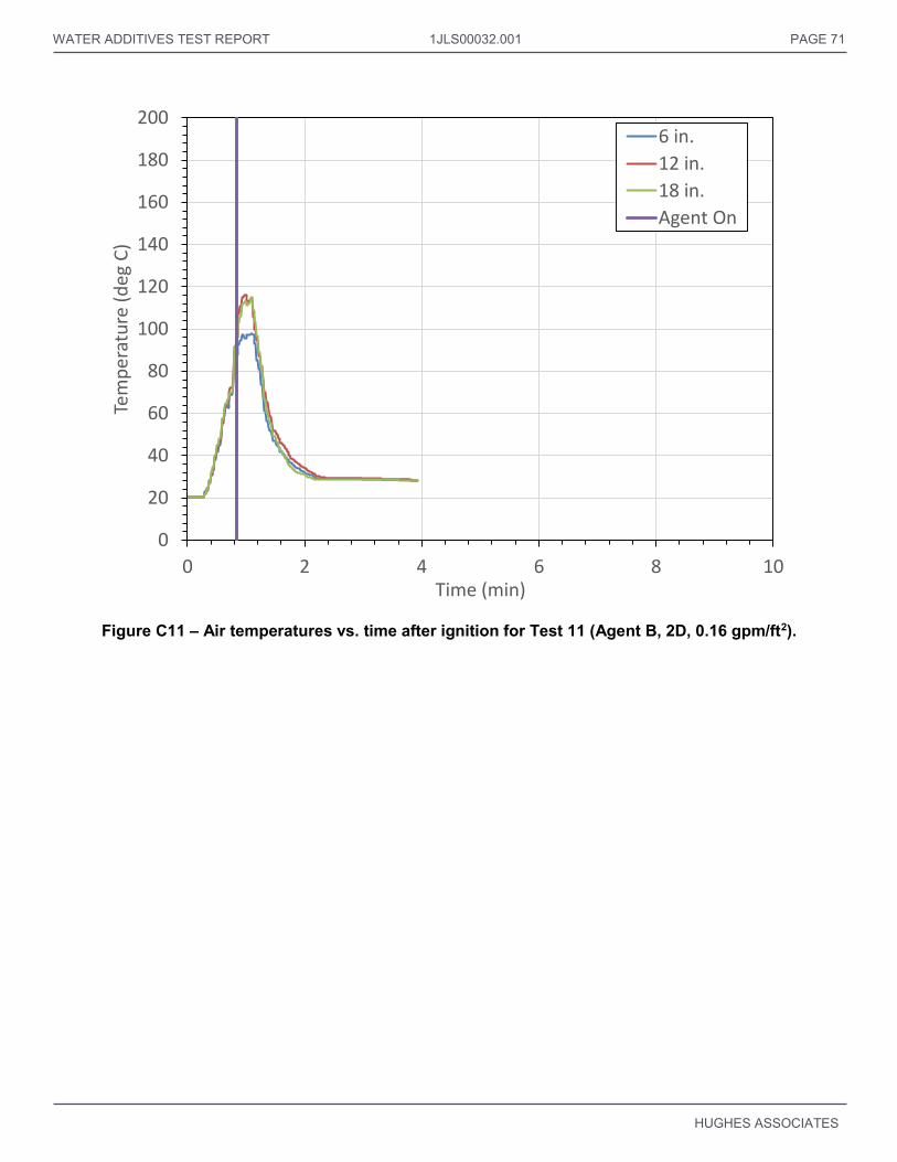
WATER ADDITIVES TEST REPORT 1JLS00032.001 PAGE 71
HUGHES ASSOCIATES
Figure C11 – Air temperatures vs. time after ignition for Test 11 (Agent B, 2D, 0.16 gpm/ft2).
0
20
40
60
80
100
120
140
160
180
200
0 2 4 6 8 10
Tem
per
atu
re (
deg
C)
Time (min)
6 in.
12 in.
18 in.
Agent On

WATER ADDITIVES TEST REPORT 1JLS00032.001 PAGE 72
HUGHES ASSOCIATES
Figure C12 – Air temperatures vs. time after ignition for Test 12 (Agent B, 2D+3D, 0.22 gpm/ft2).
0
20
40
60
80
100
120
140
160
180
200
0 2 4 6 8 10
Tem
per
atu
re (
deg
C)
Time (min)
6 in.
12 in.
18 in.
Agent On

WATER ADDITIVES TEST REPORT 1JLS00032.001 PAGE 73
HUGHES ASSOCIATES
Figure C13 – Air temperatures vs. time after ignition for Test 13 (Water, 3D, 0.3 gpm/ft2).
0
20
40
60
80
100
120
140
160
180
200
0 2 4 6 8 10
Tem
per
atu
re (
deg
C)
Time (min)
6 in.
12 in.
18 in.
Agent On

WATER ADDITIVES TEST REPORT 1JLS00032.001 PAGE 74
HUGHES ASSOCIATES
Figure C14 – Air temperatures vs. time after ignition for Test 14 (Water, 3D, 0.45 gpm/ft2).
0
20
40
60
80
100
120
140
160
180
200
0 2 4 6 8 10
Tem
per
atu
re (
deg
C)
Time (min)
6 in.
12 in.
18 in.
Agent On

WATER ADDITIVES TEST REPORT 1JLS00032.001 PAGE 75
HUGHES ASSOCIATES
Figure C15 – Air temperatures vs. time after ignition for Test 15 (Agent C, 2D, 0.3 gpm/ft2).
0
20
40
60
80
100
120
140
160
180
200
0 2 4 6 8 10
Tem
per
atu
re (
deg
C)
Time (min)
6 in.
12 in.
18 in.
Agent On

WATER ADDITIVES TEST REPORT 1JLS00032.001 PAGE 76
HUGHES ASSOCIATES
Figure C16 – Air temperatures vs. time after ignition for Test 16 (Agent C, 3D, 0.3 gpm/ft2).
0
20
40
60
80
100
120
140
160
180
200
0 2 4 6 8 10
Tem
per
atu
re (
deg
C)
Time (min)
6 in.12 in.18 in.Agent On

WATER ADDITIVES TEST REPORT 1JLS00032.001 PAGE 77
HUGHES ASSOCIATES
Figure C17 – Air temperatures vs. time after ignition for Test 17 (Agent C, 2D+3D, 0.3 gpm/ft2).
0
20
40
60
80
100
120
140
160
180
200
0 2 4 6 8 10
Tem
per
atu
re (
deg
C)
Time (min)
6 in.12 in.18 in.Agent On

WATER ADDITIVES TEST REPORT 1JLS00032.001 PAGE 78
HUGHES ASSOCIATES
Figure C18 – Air temperatures vs. time after ignition for Test 18 (Agent C, 2D, 0.16 gpm/ft2).
0
20
40
60
80
100
120
140
160
180
200
0 2 4 6 8 10
Tem
per
atu
re (
deg
C)
Time (min)
6 in.
12 in.
18 in.
Agent On

WATER ADDITIVES TEST REPORT 1JLS00032.001 PAGE 79
HUGHES ASSOCIATES
Figure C19 – Air temperatures vs. time after ignition for Test 19 (Agent C, 3D, 0.22 gpm/ft2).
0
20
40
60
80
100
120
140
160
180
200
0 2 4 6 8 10
Tem
per
atu
re (
deg
C)
Time (min)
6 in.
12 in.
18 in.

WATER ADDITIVES TEST REPORT PAGE 80
HUGHES ASSOCIATES
APPENDIX D – BEAM TEMPERATURES VS. TIME AFTER IGNITION

WATER ADDITIVES TEST REPORT PAGE 81
HUGHES ASSOCIATES
Figure D1 – Beam temperatures vs. time after ignition for Test 1 (Water, 2D, 0.3 gpm/ft2).
0
20
40
60
80
100
120
140
160
180
200
0 2 4 6 8 10
Tem
per
atu
re (
deg
C)
Time (min)
Beam Temp 1
Beam Temp 2
Beam Temp 3
Beam Temp 4
Beam Temp 5
Agent On

WATER ADDITIVES TEST REPORT 1JLS00032.001 PAGE 82
HUGHES ASSOCIATES
Figure D2 – Beam temperatures vs. time after ignition for Test 2 (Water, 2D, 0.45 gpm/ft2).
0
20
40
60
80
100
120
140
160
180
200
0 2 4 6 8 10
Tem
per
atu
re (
deg
C)
Time (min)
Beam Temp 1
Beam Temp 2
Beam Temp 3
Beam Temp 4
Beam Temp 5
Agent On

WATER ADDITIVES TEST REPORT 1JLS00032.001 PAGE 83
HUGHES ASSOCIATES
Figure D3 – Beam temperatures vs. time after ignition for Test 3 (Agent A, 2D, 0.3 gpm/ft2).
0
20
40
60
80
100
120
140
160
180
200
0 2 4 6 8 10
Tem
per
atu
re (
deg
C)
Time (min)
Beam Temp 1
Beam Temp 2
Beam Temp 3
Beam Temp 4
Beam Temp 5
Agent On

WATER ADDITIVES TEST REPORT 1JLS00032.001 PAGE 84
HUGHES ASSOCIATES
Figure D4 – Beam temperatures vs. time after ignition for Test 4 (Agent A, 3D, 0.3 gpm/ft2).
0
20
40
60
80
100
120
140
160
180
200
0 2 4 6 8 10
Tem
per
atu
re (
deg
C)
Time (min)
Beam Temp 1
Beam Temp 2
Beam Temp 3
Beam Temp 4
Beam Temp 5
Agent On

WATER ADDITIVES TEST REPORT 1JLS00032.001 PAGE 85
HUGHES ASSOCIATES
Figure D5 – Beam temperatures vs. time after ignition for Test 5 (Agent A, 2D+3D, 0.3 gpm/ft2).
0
20
40
60
80
100
120
140
160
180
200
0 2 4 6 8 10
Tem
per
atu
re (
deg
C)
Time (min)
Beam Temp 1
Beam Temp 2
Beam Temp 3
Beam Temp 4
Beam Temp 5
Agent On

WATER ADDITIVES TEST REPORT 1JLS00032.001 PAGE 86
HUGHES ASSOCIATES
Figure D6 – Beam temperatures vs. time after ignition for Test 6 (Agent A, 2D, 0.16 gpm/ft2).
0
20
40
60
80
100
120
140
160
180
200
0 2 4 6 8 10
Tem
per
atu
re (
deg
C)
Time (min)
Beam Temp 1
Beam Temp 2
Beam Temp 3
Beam Temp 4
Beam Temp 5
Agent On
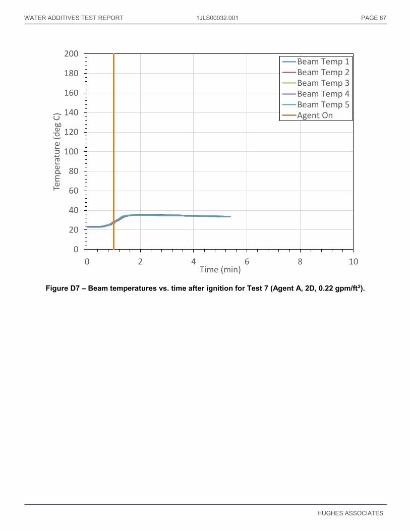
WATER ADDITIVES TEST REPORT 1JLS00032.001 PAGE 87
HUGHES ASSOCIATES
Figure D7 – Beam temperatures vs. time after ignition for Test 7 (Agent A, 2D, 0.22 gpm/ft2).
0
20
40
60
80
100
120
140
160
180
200
0 2 4 6 8 10
Tem
per
atu
re (
deg
C)
Time (min)
Beam Temp 1Beam Temp 2Beam Temp 3Beam Temp 4Beam Temp 5Agent On
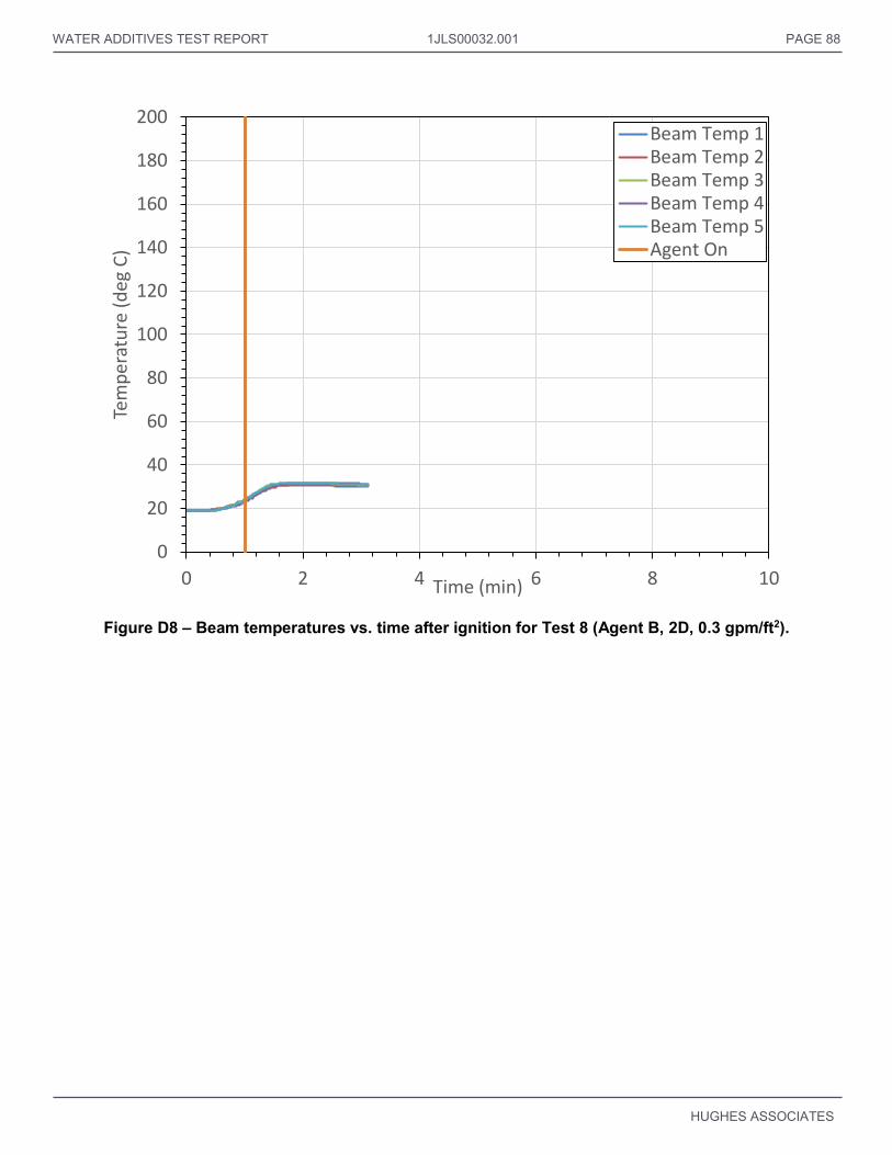
WATER ADDITIVES TEST REPORT 1JLS00032.001 PAGE 88
HUGHES ASSOCIATES
Figure D8 – Beam temperatures vs. time after ignition for Test 8 (Agent B, 2D, 0.3 gpm/ft2).
0
20
40
60
80
100
120
140
160
180
200
0 2 4 6 8 10
Tem
per
atu
re (
deg
C)
Time (min)
Beam Temp 1Beam Temp 2Beam Temp 3Beam Temp 4Beam Temp 5Agent On

WATER ADDITIVES TEST REPORT 1JLS00032.001 PAGE 89
HUGHES ASSOCIATES
Figure D9 – Beam temperatures vs. time after ignition for Test 9 (Agent B, 3D, 0.3 gpm/ft2).
0
20
40
60
80
100
120
140
160
180
200
0 2 4 6 8 10
Tem
per
atu
re (
deg
C)
Time (min)
Beam Temp 1Beam Temp 2Beam Temp 3Beam Temp 4Beam Temp 5Agent On
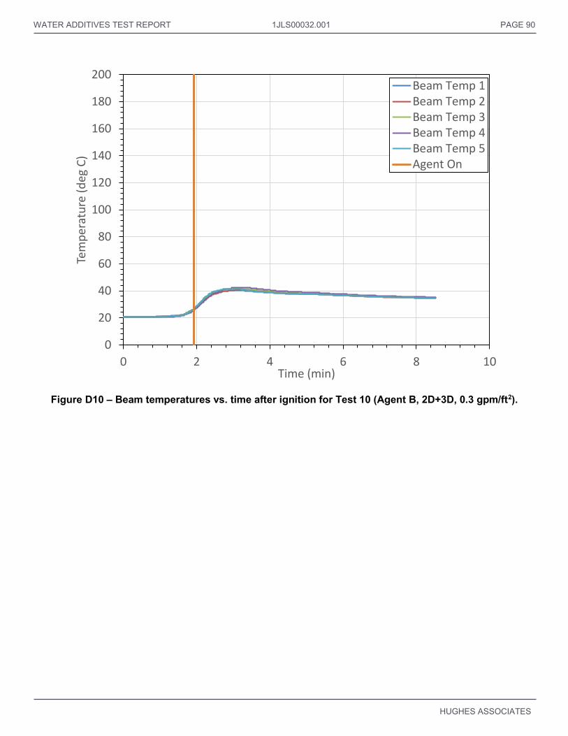
WATER ADDITIVES TEST REPORT 1JLS00032.001 PAGE 90
HUGHES ASSOCIATES
Figure D10 – Beam temperatures vs. time after ignition for Test 10 (Agent B, 2D+3D, 0.3 gpm/ft2).
0
20
40
60
80
100
120
140
160
180
200
0 2 4 6 8 10
Tem
per
atu
re (
deg
C)
Time (min)
Beam Temp 1Beam Temp 2Beam Temp 3Beam Temp 4Beam Temp 5Agent On

WATER ADDITIVES TEST REPORT 1JLS00032.001 PAGE 91
HUGHES ASSOCIATES
Figure D11 – Beam temperatures vs. time after ignition for Test 11 (Agent B, 2D, 0.16 gpm/ft2).
0
20
40
60
80
100
120
140
160
180
200
0 2 4 6 8 10
Tem
per
atu
re (
deg
C)
Time (min)
Beam Temp 1Beam Temp 2Beam Temp 3Beam Temp 4Beam Temp 5Agent On

WATER ADDITIVES TEST REPORT 1JLS00032.001 PAGE 92
HUGHES ASSOCIATES
Figure D12 – Beam temperatures vs. time after ignition for Test 12 (Agent B, 2D+3D, 0.22 gpm/ft2).
0
20
40
60
80
100
120
140
160
180
200
0 2 4 6 8 10
Tem
per
atu
re (
deg
C)
Time (min)
Beam Temp 1Beam Temp 2Beam Temp 3Beam Temp 4Beam Temp 5Agent On

WATER ADDITIVES TEST REPORT 1JLS00032.001 PAGE 93
HUGHES ASSOCIATES
Figure D13 – Beam temperatures vs. time after ignition for Test 13 (Water, 3D, 0.3 gpm/ft2).
0
20
40
60
80
100
120
140
160
180
200
0 2 4 6 8 10
Tem
per
atu
re (
deg
C)
Time (min)
Beam Temp 1
Beam Temp 2
Beam Temp 3
Beam Temp 4
Beam Temp 5
Agent On

WATER ADDITIVES TEST REPORT 1JLS00032.001 PAGE 94
HUGHES ASSOCIATES
Figure D14 – Beam temperatures vs. time after ignition for Test 14 (Water, 3D, 0.45 gpm/ft2).
0
20
40
60
80
100
120
140
160
180
200
0 2 4 6 8 10
Tem
per
atu
re (
deg
C)
Time (min)
Beam Temp 1Beam Temp 2Beam Temp 3Beam Temp 4Beam Temp 5Agent On

WATER ADDITIVES TEST REPORT 1JLS00032.001 PAGE 95
HUGHES ASSOCIATES
Figure D15 – Beam temperatures vs. time after ignition for Test 15 (Agent C, 2D, 0.3 gpm/ft2).
0
20
40
60
80
100
120
140
160
180
200
0 2 4 6 8 10
Tem
per
atu
re (
deg
C)
Time (min)
Beam Temp 1Beam Temp 2Beam Temp 3Beam Temp 4Beam Temp 5Agent On

WATER ADDITIVES TEST REPORT 1JLS00032.001 PAGE 96
HUGHES ASSOCIATES
Figure D16 – Beam temperatures vs. time after ignition for Test 16 (Agent C, 3D, 0.3 gpm/ft2).
0
20
40
60
80
100
120
140
160
180
200
0 2 4 6 8 10
Tem
per
atu
re (
deg
C)
Time (min)
Beam Temp 1Beam Temp 2Beam Temp 3Beam Temp 4Beam Temp 5Agent On

WATER ADDITIVES TEST REPORT 1JLS00032.001 PAGE 97
HUGHES ASSOCIATES
Figure D17 – Beam temperatures vs. time after ignition for Test 17 (Agent C, 2D+3D, 0.3 gpm/ft2).
0
20
40
60
80
100
120
140
160
180
200
0 2 4 6 8 10
Tem
per
atu
re (
deg
C)
Time (min)
Beam Temp 1Beam Temp 2Beam Temp 3Beam Temp 4Beam Temp 5Agent On
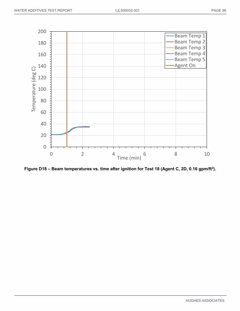
WATER ADDITIVES TEST REPORT 1JLS00032.001 PAGE 98
HUGHES ASSOCIATES
Figure D18 – Beam temperatures vs. time after ignition for Test 18 (Agent C, 2D, 0.16 gpm/ft2).
0
20
40
60
80
100
120
140
160
180
200
0 2 4 6 8 10
Tem
per
atu
re (
deg
C)
Time (min)
Beam Temp 1Beam Temp 2Beam Temp 3Beam Temp 4Beam Temp 5Agent On

WATER ADDITIVES TEST REPORT 1JLS00032.001 PAGE 99
HUGHES ASSOCIATES
Figure D19 – Beam temperatures vs. time after ignition for Test 19 (Agent C, 3D, 0.22 gpm/ft2).
0
20
40
60
80
100
120
140
160
180
200
0 2 4 6 8 10
Tem
per
atu
re (
deg
C)
Time (min)
Beam Temp 1Beam Temp 2Beam Temp 3Beam Temp 4Beam Temp 5Agent On