TECHNICAL CATALOG - Perf · TECHNICAL CATALOG: Cast Iron Zonal ... • Ratcheting lock ring holds...
26
TECHNICAL CATALOG: Cast Iron Zonal Isolation Equipment and Running Instructions © 2016 GEODynamics - All Rights Reserved
Transcript of TECHNICAL CATALOG - Perf · TECHNICAL CATALOG: Cast Iron Zonal ... • Ratcheting lock ring holds...

TECHNICAL CATALOG:Cast Iron Zonal Isolation Equipment and Running Instructions
© 2016 GEODynamics - All Rights Reserved

© 2016 GEODynamics - All Rights Reserved10244 West Interstate 20 Millsap, TX 76066 | 1001 Jarvis Road Saginaw, TX 76179 | Phone: +1.855.737.3397 | Web: www.perf.com
LEGACY LHPBPHIGH PRESSURE BRIDGE PLUGThe LEGACY™ LHPBP Bridge Plugs have proven to be a product that can be depended on. It has excellent running characteristics and secure sets. The plug can be set on different types of wireline pressure setting tools. The plugs are designed for rapid drill-out while maintaining sufficient strength during the set. This plug sustains high pressures and temperatures.
FEATURES:• Electric wireline set• Drillable• Cast iron construction• One piece slips (hardened to depth of wicker only)
• Sets in any grade casing including P-110• Form-fitting metal back-ups prevent rubber extrusion• For temporary or permanent service• Ratcheting lock ring holds setting force
Available for 2 3/8" to 20" Casing *Set with Legacy Brand Power Charges and Ignitors
SPECIFICATIONSCASING PLUG SETTING RANGE SETTING TOOL
OD WT. (LBS/FT) PART NUMBER OD MIN. MAX. BAKER GO
2 3/8 3.3 - 5.9 000-1710-002 1.71 1.867 2.107 5
2 3/8 3.3 - 5.9 000-1710-000 1.71 1.867 2.107 1 11/16
2 7/8 6.4 - 6.5 000-2100-002 2.10 2.280 2.563 5
2 7/8 6.4 - 6.5 000-2100-000 2.10 2.280 2.563 1 11/16
2 7/8 6.4 - 6.5 000-2100-000 2.10 2.280 2.563 2 1/8
3 1/2 5.7 - 10.2 000-2750-002 2.75 2.867 3.258 5
3 1/2 5.7 - 10.2 000-2750-000 2.75 2.867 3.258 10
3 1/2 5.7 - 10.2 000-2750-000 2.75 2.867 3.258 1 11/16
3 1/2 5.7 - 10.2 000-2750-000 2.75 2.867 3.258 2 1/8
4 5.6 - 14 000-3120-002 3.12 3.340 3.732 10 2 1/8
4 1/2 9.5 - 16.6 000-3500-002 3.50 3.826 4.090 10 3 1/2
4 1/2 9.5 - 13.5 000-3710-002 3.71 3.920 4.560 10 3 1/2
5 11.5 - 21 000-3710-002 3.71 3.920 4.560 10 3 1/2
5 1/2 13 - 25 000-4240-002 4.24 4.580 5.047 20 3 1/2
5 3/4 22.5 - 25.2 000-4240-002 4.24 4.580 5.047 20 3 1/2
6 14 - 26 000-4750-002 4.75 5.140 5.595 20 3 1/2
6 5/8 34 000-4750-002 4.75 5.140 5.595 20 3 1/2
6 10.5 - 12 000-5340-002 5.34 5.595 6.366 20 3 1/2
6 5/8 17 - 34 000-5340-002 5.34 5.595 6.366 20 3 1/2
7 23 - 40 000-5340-002 5.34 5.595 6.366 20 3 1/2
6 5/8 17 - 22 000-5610-002 5.61 5.989 6.655 20 3 1/2
7 17 - 35 000-5610-002 5.61 5.989 6.655 20 3 1/2
7 5/8 20 - 39 000-6090-002 6.09 6.625 7.263 20 3 1/2
8 5/8 24 - 49 000-6960-002 6.96 7.511 8.248 20 3 1/2
9 5/8 29.3 - 53.5 000-7710-002 7.71 8.435 9.063 20 3 1/2
10 3/4 54 - 81 000-8710-002 8.71 9.250 9.784 20 3 1/2
10 3/4 32.7 - 51 000-9500-002 9.50 9.850 11.150 20 3 1/2
11 3/4 38 - 60 000-9500-002 9.50 9.850 11.150 20 3 1/2
13 3/8 77 - 102 000-1156-002 11.56 11.633 12.464 20 3 1/2
13 3/8 48 - 72 000-1200-002 12.00 12.347 12.715 20 3 1/2
16 65 - 109 000-1425-002 14.25 14.688 15.250 20 3 1/2
18 5/8 76 - 96.5 000-1725-002 17.25 17.655 18.730 20 3 1/2
20 133 - 169 000-1725-002 17.25 17.655 18.730 20 3 1/2

© 2016 GEODynamics - All Rights Reserved10244 West Interstate 20 Millsap, TX 76066 | 1001 Jarvis Road Saginaw, TX 76179 | Phone: +1.855.737.3397 | Web: www.perf.com
MODEL LBP-WSBRIDGE PLUG - WIRELINE SET
The Model LBP-WS Cast Iron Drillable Bridge Plug’s modular, field proven design makes it a versatile tool in a variety of applications. The LBP-WS may be set on a wireline setting tool or set mechanically by changing the top slips. The LBP-WS also converts to a LCR-WS Cement Retainer by replacing the solid plug with a sleeve valve.
APPLICATIONS:•Well Abandonment•Temporary or Permanent zone isolation
FEATURES, ADVANTAGES, AND BENEFITS:• Cast iron drillable design• Converts between mechanical or wireline set by changing top slips• Converts to a Model LCR Cement Retainer• Temperature rating to 325° F• Differential pressure rating to 10,000 psi thru 7 5⁄8”• Convertibility reduces inventory requirements• Fast drill out saves rig time
SPECIFICATIONSCASING PLUG SETTING RANGE
OD WT. (LBS/FT) PART NUMBER OD MIN. MAX.
4 1/2 9.5 - 16.6 005-3593-003 3.593 3.826 4.090
5 11.5 - 18 005-3937-003 3.937 4.154 4.560
5 1/2 13 - 23 005-4312-003 4.312 4.580 5.044
6 10.5 - 12 005-5375-003 5.375 5.959 6.135
6 5/8 17 - 34 005-5375-003 5.375 5.959 6.135
7 32 - 38 005-5375-003 5.375 5.959 6.135
7 17 - 35 005-5687-003 5.687 6.004 6.538
7 5/8 20 - 39 005-6312-003 6.312 6.625 7.263
8 5/8 24 - 49 005-7125-003 7.125 7.511 8.248
9 5/8 29.3 - 53.5 005-8125-003 8.125 8.435 9.063
10 3/4 54 - 81 005-9000-003 9.000 9.250 9.660
10 3/4 32.7 - 51 005-9437-003 9.437 9.660 10.192
13 3/8 77 - 102 005-1156-003 11.562 11.633 12.464
13 3/8 48 - 72 005-1200-003 12.000 12.175 12.715

© 2016 GEODynamics - All Rights Reserved10244 West Interstate 20 Millsap, TX 76066 | 1001 Jarvis Road Saginaw, TX 76179 | Phone: +1.855.737.3397 | Web: www.perf.com
MODEL LCR-WSSLEEVE VALVE CEMENT RETAINER - WIRELINE SET
The Model LCR-WS Cast Iron Drillable Cement Retainer’s modular, field proven design makes it a versatile tool in a variety of applications. The SVCR (Sleeve Valve Cement Retainer) may be set on a wireline setting tool or mechanically by changing the top slips. The SVCR also converts to a LBP Bridge Plug by replacing the sleeve valve with a solid plug.
APPLICATIONS:•Cementing•Stimulation•Well Abandonment•Temporary or Permanent zone isolation
AVAILABLE FOR 4 1/2” TO 13 3/8” CASINGALSO AVAILABLE IN MECHANICAL SET
FEATURES, ADVANTAGES, AND BENEFITS:• Cast iron drillable design• Simple, surface-controlled valve automatically closes when the stinger is removed• Converts between mechanical or wireline set by changing top slips• Converts to a Model LBP Bridge Plug• Temperature rating to 325° F• Differential pressure rating to 10,000 psi thru 7 5⁄8”• Allows pressure testing before squeeze• Valve protects sensitive zones in low-fluid wells• Convertibility reduces inventory requirements• Fast drill out saves rig time
SPECIFICATIONSCASING RETAINER SETTING RANGE
OD WT. (LBS/FT) PART NUMBER OD MIN. MAX.
4 1/2 9.5 - 16.6 005-3593-002 3.593 3.826 4.090
5 11.5 - 18 005-3937-002 3.937 4.154 4.560
5 1/2 13 - 23 005-4312-002 4.312 4.580 5.044
6 10.5 - 12 005-5375-002 5.375 5.959 6.135
6 5/8 17 - 34 005-5375-002 5.375 5.959 6.135
7 32 - 38 005-5375-002 5.375 5.959 6.135
7 17 - 35 005-5687-002 5.687 6.004 6.538
7 5/8 20 - 39 005-6312-002 6.312 6.625 7.263
8 5/8 24 - 49 005-7125-002 7.125 7.511 8.248
9 5/8 29.3 - 53.5 005-8125-002 8.125 8.435 9.063
10 3/4 54 - 81 005-9000-002 9.000 9.250 9.660
10 3/4 32.7 - 51 005-9437-002 9.437 9.660 10.192
13 3/8 77 - 102 005-1156-002 11.562 11.633 12.464
13 3/8 48 - 72 005-1200-002 12.000 12.175 12.715

© 2016 GEODynamics - All Rights Reserved10244 West Interstate 20 Millsap, TX 76066 | 1001 Jarvis Road Saginaw, TX 76179 | Phone: +1.855.737.3397 | Web: www.perf.com
Guidelines for Running Legacy™ Oil Tools Wireline Set Bridge PlugsLegacy High Pressure (LHPBP), Legacy Low Pressure (LLPBP) & Convertible LBP
1. Use casing scraper before running any equipment in the well to remove scale and other materials from the casing wall. Any tool that is expected to grip the casing wall has to first reach the casing wall. Follow scraper with gage ring and junk basket.
2. Always follow cleaning, redressing and operational procedures on the setting tools. We recommend using Legacy™ Oil Tools power charges and ignitors with wireline pressure setting tools. Make certain oil levels in pressure setting tool are correct for the well environment involved. Take into consideration the heat expansion of the oil in your manufacturer’s guidelines that should be supplied with your wireline pressure setting tool.
3. Use the correct bridge plug for the temperature, pressure, casing size, casing weight and environment.
Legacy High Pressure Bridge Plug (LHPBP) Pressure Temperature2 3/8” tubing thru 7 5/8” casing (1.71 – 6.09 plugs) 10,000 psi 325˚ F
8 5/8” thru 9 5/8” casing (6.96 – 7.71 plugs) 8,000 psi 300˚ F
10 3/4” thru 113/4” casing (8.71 – 9.50 plugs) 5,000 psi 300˚ F
13 3/8” casing (11.56 – 12.0 plugs) 3,000 psi 300˚ F
16” casing (14.25 plugs) 2,000 psi 200˚ F
18 5/8” thru 20” casing (17.25 plugs) 2,000 psi 200˚ F
Legacy Low Pressure Bridge Plug (LLPBP) Pressure Temperature2 3/8” tubing thru 7” casing (1.71 – 5.61 plugs) 6,000 psi 200˚ F
4. Casing should have 100% cement bond before running plug in the well.
5. Do not over-tighten bridge plug onto setting tool. This action causes the slips to crack which leads to premature setting. Snug tight is sufficient for a bridge plug. The lock spring or nut, depending on make of setting tool, must accompany the tension mandrel to prevent plug from backing off.
6. Do not allow the setting tool weight to rest on the bridge plug after making up. This can cause the slip to crack.
7. Help guide the setting tool and bridge plug through lubricators, wellhead and blowout preventer. When running under pressure raise tools to the top of lubricator before equalizing the pressure into lubricator.
8. Running speed should not exceed 300 feet per minute to avoid fluid displacement cutting on elastomer. Should setting tool misfire, retrieve equipment no faster than it went in. Slow down for liners and other restrictions.
9. Never set plug in casing collar or where milling has occurred.
10. Always set plugs in static well conditions (no fluid or gas movement).
11. Shock to the plug can result in failure. Warn service companies of the plug depth to avoid high impact collisions. When using the plug for locating purposes, be gentle and ease tools onto plug. Never place tubing weight on plug.

© 2016 GEODynamics - All Rights Reserved10244 West Interstate 20 Millsap, TX 76066 | 1001 Jarvis Road Saginaw, TX 76179 | Phone: +1.855.737.3397 | Web: www.perf.com
12. Wireline setting tools, which rely on internal pressure to make the setting tool function, can fail for various reasons (for example, a bad o-ring or incorrect volume of oil in the chamber). In the event that a pressure setting tool does not shear off of the bridge plug and you have to pull out of the rope socket, the shear stud will still part in a normal manner when the setting tool is fished out. This happens most commonly because sufficient pressure was not applied in order to shear the stud in the plug. Legacy™ Oil Tools studs are made to shear correctly and are held to high standards of accuracy. When the fishing tools retrieve the setting tool, you can watch the accuracy of the shear stud when it shears, assuming that the weight indicator is not out of calibration. The shear values are listed as follows:
Size of Plug (O.D.) Shear Stud Value1.710” thru 2.750” 12,000 lbs.
3.120” 25,000 lbs.
3.500” thru 4.750” 30,000 lbs.
5.340” thru 12.000” 50,000 lbs.
13. When perforating above a plug, bridge plug should be protected with a minimum of ten feet of cement dumped directly on top of plug. Cement should be given sufficient time to set up before perforating.
14. Perforating should not be done closer than fifty feet of bridge plug.

© 2016 GEODynamics - All Rights Reserved10244 West Interstate 20 Millsap, TX 76066 | 1001 Jarvis Road Saginaw, TX 76179 | Phone: +1.855.737.3397 | Web: www.perf.com
Guidelines for Running Legacy™ Oil ToolsWireline Set Cement Retainers: Legacy™ Convertible LCR
1. Use casing scraper before running any equipment in the well to remove scale and other materials from the casing wall. Any tool that is expected to grip the casing wall has to first reach the casing wall. Follow scraper with gage ring and junk basket.
2. Always follow cleaning, redressing and operational procedures on the setting tool. We recommend using Legacy™ Oil Tools power charges and ignitors with wireline pressure setting tools. Make certain oil levels in pressure setting tool are correct for the well environment involved. Take into consideration the expansion of the oil in your manufacturer’s guidelines that should be supplied with your pressure setting tool.
3. Use the correct cement retainer for the temperature, pressure, casing size, casing weight and environment.
Sleeve Valve Cement Retainer Pressure Temperature4 1/2” thru 7 5/8” casing (3.593 – 6.312 Model B) 10,000 psi 325˚ F
8 5/8” thru 9 5/8” casing (7.125 – 8.125 Model B) 8,000 psi 300˚ F
10 3/4” thru 11 3/4” casing (9.000 – 10.437 Model B) 5,000 psi 300˚ F
13 3/8” casing (11.562 – 12.000 Model B) 3,000 psi 300˚ F
4. Casing should have 100% cement bond before running cement retainer in the well.
5. Do not over-tighten cement retainer onto setting tool. This action causes the slips to crack which leads to premature setting. Snug tight is sufficient for a cement retainer. The lock spring or nut, depending on make of setting tool, must accompany the tension mandrel to prevent plug from backing off.
6. Do not allow the setting tool weight to rest on the cement retainer after making up. This can cause the slips to crack.
7. Help guide the setting tool and cement retainer through lubricators, wellhead and blowout preventer. When running under pressure raise tools to the top of lubricator before equalizing the pressure into lubricator.
8. Running speed should not exceed 300 feet per minute to avoid fluid displacement cutting on elastomer. Should setting tool misfire, retrieve equipment no faster than it went in. Slow down for liners and other restrictions.
9. Never set retainer in casing collar or where milling has occurred.
10. Always set retainer in static well conditions (no fluid or gas movement).
11. Shock to the retainer can result in failure. Warn service companies of the retainer depth to avoid high impact collisions. Never use a cement retainer for a reference point (tagging) before cement job is completed.

© 2016 GEODynamics - All Rights Reserved10244 West Interstate 20 Millsap, TX 76066 | 1001 Jarvis Road Saginaw, TX 76179 | Phone: +1.855.737.3397 | Web: www.perf.com
Size of Retainer (O.D.) Shear Stud Value1.710” thru 2.750” 12,000 lbs.
3.120” 25,000 lbs.
3.593” thru 4.937” Model B 30,000 lbs.
5.374” thru 12.000” Model B 50,000 lbs.
12. Wireline setting tools, which use internal pressure to function the tool can fail due to several causes (ex. bad o-ring or incorrect volume of oil in the chamber). In the event that a pressure setting tool does not shear off of the cement retainer and you have to pull out of the rope socket, the shear stud will still part in a normal manner when the setting tool is fished out. This happens most commonly because sufficient pressure was not applied in order to shear the stud in the retainer. The Legacy™ studs are made to shear correctly and are held to high standards of accuracy. When the fishing tools go in to retrieve the setting tool, you can watch the accuracy of the shear stud when it shears, assuming that the weight indicator is not out of calibration. The shear values are as follows:
13. When perforating above a cement retainer, the cement retainer should be protected with a minimum of ten feet of cement dumped directly on top of retainer. Cement should be given sufficient time to set up before perforating.
14. Perforating should not be done closer than fifty feet of cement retainer without putting a minimum of 10 ft. of hard cement on the retainer.
15. Make seal nipple up on a 4ft. tubing sub (if available); if not, use stop collar to prevent centralizer from moving up the full length of tubing joint. Centralizer should not be more than 10 ft. from top of seal nipple. Go in hole at normal speed. Be sure and strap the tubing and keep accurate measurements. When the seal nipple assembly has been lowered to approximately 200 ft. above the cement retainer, slow down and ease tubing in the hole, being careful not to run into the cement retainer. After top of cement retainer has been tagged with seal nipple assembly, lower seal nipple into retainer until 10,000 lbs. down force has been applied. To test tubing, raise tubing until all tubing weight is picked up and a slight pull on tubing is encountered. Pressure can be applied to tubing for tubing test. After test is completed release pressure.
SPEC
IFIC
ATIO
NS
CASI
NG
PLU
G S
ETTI
NG
RA
NG
E S
ETTI
NG
FO
RCE
(lbs)
BAK
ER S
TYLE
SET
TIN
G E
QU
IPM
ENT
GO
STY
LE S
ETTI
NG
EQ
UIP
MEN
T
OD
WT.
(L
BS/F
T)PA
RT N
UM
BER
OD
MIN
. M
AX.
SET
TIN
G T
OO
L P
OW
ER C
HARG
E IG
NIT
OR
ADA
PTER
KI
T**
SET
TIN
G S
LEEV
E A
DJU
STER
SU
B S
OCK
ET H
EAD
SET
SCRE
W LO
CK
SPRI
NG
T
ENSI
ON
M
ANDR
EL
SET
TIN
G
TOO
L P
OW
ER C
HARG
E IG
NIT
OR
ADA
PTER
KI
T***
S
ETTI
NG
SL
EEVE
AD
APTE
R RO
DLO
CK N
UT
2 3/
83.
3 - 5
.900
0-17
10-0
02 1
.710
1
.867
2
.107
7
,000
# #
5 0
00-1
710-
000
Not
Req
uire
d N
ot R
equi
red
Not
Req
uire
d N
ot R
equi
red
1-11
/16
1-1/
2PC
-150
0-20
1 (L
ow-T
emp)
PC
-168
8-40
1 (H
igh-
Tem
p)
DT-
0425
-101
w/
grou
nd c
lip
DT-
0425
-102
w/
grou
nd w
ire
000-
1710
-101
Not
Req
uire
dN
ot R
equi
red
2 7/
86.
4 - 6
.500
0-21
00-0
02 2
.100
2
.280
2
.563
0
00-2
100-
200
000-
2100
-101
3 1/
25.
7 - 1
0.2
000-
2750
-002
2.7
50
2.8
67
3.2
58
000
-275
0-20
0 2-
1/8
000-
2750
-101
4 5.
6 - 1
400
0-31
20-0
02 3
.120
3
.340
3
.732
2
0,00
0#
#10
LEG
ACY
#10
PC
-131
2-01
0 Lo
w-T
emp
DT-
0425
-101
w/
grou
nd c
lip
DT-
0425
-102
w/
grou
nd w
ire
000
-312
0-90
0 0
00-3
120-
200
000
-350
0-20
3
000
-312
0-20
6 P
C-21
25-2
02 (L
ow-T
emp)
00
0-31
20-1
00
4 1/
29.
5 - 1
6.6
000-
3500
-002
00
0-35
00-0
04 3
.500
3
.826
4
.090
30,
000#
WR1
5*
PC-
3625
-201
Lo
w-T
emp
000
-350
0-90
0 0
00-3
500-
200
000
-350
0-20
6
3-1/
2 3-
5/8
WPC
-350
0-20
1 Lo
w-T
emp
PC
-362
5-20
1 Lo
w-T
emp
000
-350
0-93
0 00
0-35
00-1
00
000-
3500
-106
000-
3500
-107
9.5
- 13.
500
0-37
10-0
02
000-
3710
-004
3.7
10
3.9
20
4.5
60
5 11
.5 -
215
1/2
13 -
2500
0-42
40-0
02
000-
4240
-004
4.2
40
4.5
80
5.0
47
000
-424
0-90
0 0
00-4
240-
200
000
-424
0-20
9 5
/16
- 18
X 3/
8 0
00-4
240-
203
000
-424
0-20
6
000
-424
0-93
0 00
0-42
40-1
005
3/4
22.5
- 25
.26
14 -
2600
0-47
50-0
02 4
.750
5
.140
5
.595
6
5/8
346
10.5
- 12
000-
5340
-002
5.3
40
5.5
95
6.3
66
55,
000#
#
20
LEG
ACY
#20
PC
-162
5-02
0 Lo
w-T
emp
000
-561
0-90
0 0
00-5
610-
200
000
-561
0-93
0 00
0-56
10-1
00
000-
5610
-106
6 5/
817
- 34
7 23
- 40
6 5/
817
- 22
000-
5610
-002
00
0-56
10-0
04 5
.610
5
.989
6
.655
7
17 -
357
5/8
20 -
3900
0-60
90-0
02 6
.090
6
.625
7
.263
0
00-6
090-
900
000
-609
0-20
0 0
00-6
090-
930
000-
6090
-100
8 5/
824
- 49
000-
6960
-002
6.9
60
7.5
11
8.2
48
000
-696
0-90
0 0
00-6
960-
200
000
-696
0-93
0 00
0-69
60-1
009
5/8
29.3
- 53
.500
0-77
10-0
02 7
.710
8
.435
9
.063
0
00-7
710-
900
000
-771
0-20
0 0
00-7
710-
930
000-
7710
-100
10 3
/454
- 81
000-
8710
-002
8.7
10
9.2
50
9.7
84
000
-871
0-90
0 0
00-8
710-
200
000
-871
0-93
0 00
0-87
10-1
00
32.7
- 51
000-
9500
-002
9.5
00
9.8
50
11
.150
0
00-9
500-
900
000
-950
0-20
0
000
-561
0-20
6
000
-950
0-93
0 00
0-95
00-1
0011
3/4
38 -
6000
0-95
00-0
02 9
.500
9
.850
11.1
50
13 3
/877
- 10
200
0-11
56-0
02 1
1.56
0 1
1.63
3
12.4
64
000
-115
6-90
0 0
00-1
156-
200
000
-115
6-93
0 00
0-11
56-1
00
48 -
7200
0-12
00-0
02 1
2.00
0 1
2.34
7
12.7
15
000
-120
0-90
0 0
00-1
200-
200
000
-120
0-93
0 00
0-12
00-1
00
16
65 -
109
000-
1425
-002
14.
250
14.
688
15
.250
0
00-1
425-
900
000
-142
5-20
0 0
00-1
425-
930
000-
1425
-100
18 5
/876
- 96
.500
0-17
25-0
02 1
7.25
0 1
7.65
5
18.7
30
000
-172
5-90
0 0
00-1
725-
200
000
-172
5-93
0 00
0-17
25-1
0020
13
3 - 1
69*
WR
15 u
ses
Bake
r sty
le te
nsio
n m
andr
el w
ith a
GO
setti
ng s
leev
e**
Ada
pter
Kit
incl
uide
s (S
etting
Sle
eve,
Adj
uste
r Sub
, Soc
ket H
ead
Set S
crew
, Loc
k Sp
ring
and
Tens
ion
Man
drel
)**
* Ad
apte
r kit
incl
udes
(Setti
ng S
leev
e, A
dapt
er R
od a
nd L
ock
Nut
)
SPEC
IFIC
ATIO
NS
CASI
NG
PLU
G S
ETTI
NG
RAN
GE
SET
TIN
G
FORC
E (lb
s)
SET
TIN
G
TOO
L P
OW
ER C
HARG
E B
AKER
STY
LE S
ETTI
NG
ADA
PTER
S
OD
WT.
(L
BS/F
T)PA
RT N
UM
BER
OD
MIN
. M
AX.
IGN
ITO
R A
DAPT
ER
KIT*
* S
ETTI
NG
SL
EEVE
S
TUB
SLEE
VE
BUSH
ING
A
DJU
STER
SU
B S
OCK
ET H
EAD
SET
SCRE
W
LOCK
SPR
ING
T
ENSI
ON
M
ANDR
EL
4 1/
29.
5 - 1
6.6
005-
3593
-002
3.5
93
3.8
26
4.0
90
30,
000#
#
10
WR1
5*
PC-
1312
-010
P
C-36
25-2
01
Low
-Tem
p
DT-
0425
-101
w/
grou
nd c
lip
DT-
0425
-102
w/
grou
nd w
ire
005
-359
3-90
0 0
05-3
593-
200
NO
T RE
QU
IRED
NO
T RE
QU
IRED
N
OT
REQ
UIR
ED
005
-359
3-20
3 0
05-3
593-
205
5 11
.5 -
2100
5-39
37-0
02 3
.937
4
.154
4
.560
0
05-3
937-
900
005
-393
7-20
0
000
-424
0-20
9 5
/16
- 18
X 3/
8 0
00-4
240-
203
005
-393
7-20
5 5
1/2
13 -
2500
5-43
12-0
02 4
.312
4
.580
5
.044
0
05-4
312-
900
005
-431
2-20
0 6
10.5
- 12
005-
5357
-002
5.3
75
5.5
95
6.1
35
005
-568
7-90
0 0
05-5
687-
200
005
-568
7-20
5
6 5/
817
- 34
7 23
- 40
55,
000#
#
20
PC-
1625
-020
17 -
3500
5-56
87-0
02 5
.687
6
.004
6
.538
7
5/8
20 -
3900
5-63
12-0
02 6
.312
6
.625
7
.263
0
05-6
312-
900
005
-631
2-20
0 8
5/8
24 -
4900
5-71
25-0
02 7
.125
7
.511
8
.248
0
05-7
125-
900
005
-712
5-20
0 9
5/8
29.3
- 53
.500
5-81
25-0
02 8
.125
8
.435
9
.063
0
05-8
125-
900
005
-812
5-20
0
005
-812
5-21
0
10 3
/454
- 81
005-
9000
-002
9.0
00
9.2
50
9.6
60
005
-900
0-90
0 0
05-9
000-
200
32.7
- 51
005-
9437
-002
9.4
37
9.6
60
10
.192
0
05-9
437-
900
005
-943
7-20
0
13 3
/877
- 10
200
5-11
56-0
02 1
1.56
0 1
1.63
3
12.4
64
005
-115
6-90
0 0
05-1
156-
200
48 -
7200
5-12
00-0
02 1
2.00
0 1
2.17
5
12.7
15
005
-120
0-90
0 0
05-1
200-
200
* W
R 15
use
s Ba
ker s
tyle
tens
ion
man
drel
with
a G
O s
etting
sle
eve
** A
dapt
er k
it in
clud
es (S
etting
sle
eve,
Stu
b Sl
eeve
Bus
hing
, Adj
uste
r Sub
, Soc
ket H
ead
Set S
crew
and
Ten
sion
Man
drel
)
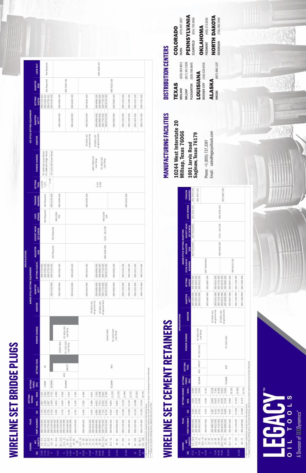
WIR
ELIN
E SET
BRI
DGE P
LUGS
WIR
ELIN
E SET
CEM
ENT R
ETAI
NERS
TEX
AS
MID
LAND
(432
) 563
.991
1
MIL
LSAP
(81
7) 3
41.5
328
PLEA
SANT
ON
(83
0) 5
69.8
645
LOU
ISIA
NA
BOSS
IER
CITY
(3
18) 6
29.0
416
ALA
SK
ANI
KISK
I
(9
07) 6
90.1
107
1024
4 W
est I
nter
stat
e 20
Mill
sap,
Texa
s 76
066
1001
Jarv
is R
oad
Sagi
naw,
Texa
s 76
179
Phon
e: +
1 (8
55) 7
37.3
397
Emai
l:
sales
@leg
acyo
iltoo
ls.co
m
MANU
FACT
URIN
G FA
CILI
TIES
DIST
RIBU
TION
CEN
TERS
CO
LOR
AD
ONU
NN
(9
70) 8
97.2
657
PEN
NS
YLV
AN
IACL
EARF
IELD
(814
) 765
.950
0
OK
LAH
OM
API
EDM
ONT
(40
5) 3
73.9
256
NO
RTH
DA
KO
TADI
CKIN
SON
(701
) 483
.764
0
© 2
016
GEO
Dyn
amic
s - A
ll R
ight
s R
eser
ved
R
evis
ed: 0
6 J
uly
201
6
A Di
vision
of G
EODy
nami
cs®

© 2016 GEODynamics - All Rights Reserved10244 West Interstate 20 Millsap, TX 76066 | 1001 Jarvis Road Saginaw, TX 76179 | Phone: +1.855.737.3397 | Web: www.perf.com
MODEL LBP-MSBRIDGE PLUG - MECHANICAL SET
The Model LBP-MS Cast Iron Drillable Bridge Plug’s modular, field proven design makes it a versatile tool in a variety of applications. The LBP-MS may be set mechanically or on a wireline setting tool by changing the top slips. The LBP-MS also converts to a LCR-MS Cement Retainer by replacing the solid plug with a sleeve valve.
SPECIFICATIONSCASING PLUG SETTING RANGE
OD WT. (LBS/FT) PART NUMBER OD MIN. MAX.
4 1/2 9.5 - 16.6 005-3593-001 3.593 3.826 4.090
5 11.5 - 18 005-3937-001 3.937 4.154 4.560
5 1/2 13 - 23 005-4312-001 4.312 4.580 5.044
6 10.5 - 12 005-5375-001 5.375 5.959 6.135
6 5/8 17 - 34 005-5375-001 5.375 5.959 6.135
7 32 - 38 005-5375-001 5.375 5.959 6.135
7 17 - 35 005-5687-001 5.687 6.004 6.538
7 5/8 20 - 39 005-6312-001 6.312 6.625 7.263
8 5/8 24 - 49 005-7125-001 7.125 7.511 8.248
9 5/8 29.3 - 53.5 005-8125-001 8.125 8.435 9.063
10 3/4 54 - 81 005-9000-001 9.000 9.250 9.660
10 3/4 32.7 - 51 005-9437-001 9.437 9.660 10.192
13 3/8 77 - 102 005-1156-001 11.562 11.633 12.464
13 3/8 48 - 72 005-1200-001 12.000 12.175 12.715
APPLICATIONS:•Well Abandonment•Temporary or Permanent zone isolation
FEATURES, ADVANTAGES, AND BENEFITS:• Cast iron drillable design• Converts between mechanical or wireline set by changing top slips• Converts to a Model LCR Cement Retainer• Temperature rating to 325° F• Differential pressure rating to 10,000 psi thru 7 5⁄8”• Convertibility reduces inventory requirements• Fast drill out saves rig time

© 2016 GEODynamics - All Rights Reserved10244 West Interstate 20 Millsap, TX 76066 | 1001 Jarvis Road Saginaw, TX 76179 | Phone: +1.855.737.3397 | Web: www.perf.com
MODEL LCR-MSSLEEVE VALVE CEMENT RETAINER - MECHANICAL SET
The Model LCR-MS Cast Iron Drillable Cement Retainer’s modular, field proven design makes it a versatile tool in a variety of applications. The SVCR (Sleeve Valve Cement Retainer) may be set mechanically or on a wireline setting tool by changing the top slips. The SVCR also converts to a LBP Bridge Plug by replacing the sleeve valve with a solid plug.
APPLICATIONS:•Cementing•Stimulation•Well Abandonment•Temporary or Permanent zone isolation
FEATURES, ADVANTAGES, AND BENEFITS:• Cast iron drillable design• Simple, surface-controlled valve automatically closes when the stinger is removed• Converts between mechanical or wireline set by changing top slips• Converts to a Model LBP Bridge Plug• Temperature rating to 325° F• Differential pressure rating to 10,000 psi thru 7 5⁄8”• Allows pressure testing before squeeze• Valve protects sensitive zones in low-fluid wells• Convertibility reduces inventory requirements• Fast drill out saves rig time
AVAILABLE FOR 4 1/2” TO 13 3/8” CASINGALSO AVAILABLE IN WIRELINE SET
SPECIFICATIONSCASING RETAINER SETTING RANGE
OD WT. (LBS/FT) PART NUMBER OD MIN. MAX.
4 1/2 9.5 - 16.6 005-3593-000 3.593 3.826 4.090
5 11.5 - 18 005-3937-000 3.937 4.154 4.560
5 1/2 13 - 23 005-4312-000 4.312 4.580 5.044
6 10.5 - 12 005-5375-000 5.375 5.959 6.135
6 5/8 17 - 34 005-5375-000 5.375 5.959 6.135
7 32 - 38 005-5375-000 5.375 5.959 6.135
7 17 - 35 005-5687-000 5.687 6.004 6.538
7 5/8 20 - 39 005-6312-000 6.312 6.625 7.263
8 5/8 24 - 49 005-7125-000 7.125 7.511 8.248
9 5/8 29.3 - 53.5 005-8125-000 8.125 8.435 9.063
10 3/4 54 - 81 005-9000-000 9.000 9.250 9.660
10 3/4 32.7 - 51 005-9437-000 9.437 9.660 10.192
13 3/8 77 - 102 005-1156-000 11.562 11.633 12.464
13 3/8 48 - 72 005-1200-000 12.000 12.175 12.715

© 2016 GEODynamics - All Rights Reserved10244 West Interstate 20 Millsap, TX 76066 | 1001 Jarvis Road Saginaw, TX 76179 | Phone: +1.855.737.3397 | Web: www.perf.com
MODEL “B”MECHANICAL SETTING TOOL
MODEL LBP-MS MODEL LCR-MS
The Legacy™ Oil Tools Model B Mechanical Setting Tool is designed to run and set the Legacy™ LCR-MS Sleeve Valve Cement Retainer and LBP-MS. It is easy to operate and has low maintenance.
This tool incorporates both a stinger seal and built-in snap latch allowing the tool to be latched into the retainer with set-down weight and released with up-strain and/or right hand rotation. This tool can be run time after time by simply moving the drive housing into the running position. Disassembly is not required every time.
Available for 4 1/2" to 13 3/8" Casing
* no additional hardware required to operate the equipment
MODEL B IS COMPATIBLE WITH THE FOLLOWING:

© 2016 GEODynamics - All Rights Reserved10244 West Interstate 20 Millsap, TX 76066 | 1001 Jarvis Road Saginaw, TX 76179 | Phone: +1.855.737.3397 | Web: www.perf.com
Legacy™ Oil Tools Model B Mechanical Setting ToolFor LCR-MS Sleeve Valve Cement Retainers or LBP-MS Bridge Plugs
The Model B Mechanical Setting Tool is designed to run and set Legacy’s Model LCR-MS Sleeve Valve Cement Retainer or LBP-MS Bridge Plug. Ease of operation and low maintenance are evident in the design. The tool incorporates both a stinger seal and built-in snap latch allowing the tool to be latched into the retainer with set down weight and released with up-strain or right-hand rotation. This tool can be run time after time by simply moving the drive housing (slip nut on smaller sizes) into place and installing new shear screws. Disassembly and redress are not generally required between runs on the same location. However, upon returning to the shop it is highly recommended that the tool be disassembled and redressed. Legacy™ Oil Tools has sizes available from 4-1/2” through 13-3/8” casing. The Model LBP Mechanical Set Bridge Plug can be run with this tool as well by removing items 23 through 27 and replacing item 1 with item 30.
INSTALLATION OF RETAINER OR BRIDGE PLUG ON THE MODEL B MECHANICAL SETTING TOOL
1. Place top collar of the mechanical setting tool in the vice.2. Rotate drag housing to the right until it stops on the clutch and stops.3. Rotate Slip retaining sleeve towards the drag housing until it stops.4. (3.593-4.312 OD) Align the holes in the slip nut with the groove in the lower mandrel.5. (5.375-12.000 OD) Align the holes in the drive housing with the groove in the lower mandrel.6. Install shear screws through the slip nut into the groove on the lower mandrel.7. Loosen clamp on slips enough to slide over upset on slip nut then retighten.8. Apply grease to the stinger sub and latch.9. Apply a liberal amount of grease to the retainer bore.10. Slide retainer / bridge plug over stinger using a quick motion. If necessary, place a block of wood across the end of the
retainer or plug and strike with a dead blow hammer.11. Rotate retainer to make up left hand thread of the latch. Stop when the holes in the latch align with the holes in the body
of retainer.12. Loosen hose clamp on slips, install torque screw furnished with the retainer. Retighten hose clamp.13. Lubricate upper non-wickered portion of slips with grease.14. (3.593-4.312 OD) With the slip retaining sleeve butted against the stop ring, rotate the slip retaining sleeve down over the
mechanical slips, remove hose clamp, continue to rotate slip retaining sleeve until it bottoms out on wickered portion of slips. Back up slip retaining sleeve ½ turn. Tighten the set screw in slip retaining sleeve.
15. (5.375-12.000 OD) With the adjuster sleeve butted against the stop ring, rotate the adjuster sleeve down over the mechanical slips, remove hose clamp, continue to rotate adjuster sleeve until it bottoms out on wickered portion of slips. Back up slip retaining sleeve ½ turn. Tighten the set screw in adjuster sleeve.
16. Tighten clamp on upper slips for transport purposes.17. Remove clamp on slips before running in well.

© 2016 GEODynamics - All Rights Reserved10244 West Interstate 20 Millsap, TX 76066 | 1001 Jarvis Road Saginaw, TX 76179 | Phone: +1.855.737.3397 | Web: www.perf.com
Legacy™ Oil Tools Model B Mechanical Setting ToolFor LCR-MS Sleeve Valve Cement Retainers or LBP-MS Bridge Plugs
RUNNING INSTRUCTIONS1. The tool should be run at a moderate speed avoiding sudden stops.
2. Avoid right-hand rotation transmitted to the setting tool. As a precaution, after every 10 stands of tubing or drill pipe can be rotated to the left by hand until the torque is felt.
3. At desired setting depth, rotate tubing to the right a minimum of seven turns, this releases the slips onto the cone.
4. Pull into the tubing in one continuous pull. See chart below to view the recommended tension. It is important to calculate this tension through tubing stretch. Do not rely on weight indicators.
5. After desired pull is reached, hold tension approximately five minutes, then slack off pipe and set approximately five to ten thousand pounds of weight down insuring retainer or plug is securely set.
TEST OPTIONS1. The tubing or drill pipe can be pressure tested by simply pulling up five thousand pounds at the tool and applying pump
pressure to the tubing.
2. The retainer can now be tested for seal-off by applying pressure down the annulus or by slacking off five thousand pounds of weight on retainer and applying pump pressure down the tubing and pumping into formation.
• These tests are performed before the setting tool is released from the cement retainer or bridge plug. • If seal-off has not been accomplished, up-strain on the tubing can again be applied and the tools can be retested until seal-off is accomplished.
RELEASING SETTING TOOL FROM CEMENT RETAINER OR BRIDGE PLUG1. Hold an up-strain of approximately one thousand pounds on the tubing.
2. Apply torque to the right until torque screws are sheared. Each screw requires 200 – 400 foot-pounds.
3. Continue right-hand rotation for ten turns or until latch is felt releasing.
• After releasing from retainer, the setting tool can be re-latched into the retainer with three to five thousand pounds set-down weight. • The valve will open when the stinger is fully engaged into the retainer and will close with a 2-inch upstroke at the tool. The stinger will remain sealed in the bore as long as snap-out force is not exceeded.
Tool Size Minimum Tension Maximum Tension3.593”- 4.312” 22,000 lbs. 30,000 lbs.
5.375”- 6.312” 30,000 lbs. 45,000 lbs.
7.125”- 12.00” 35,000 lbs. 48,000 lbs.

© 2016 GEODynamics - All Rights Reserved10244 West Interstate 20 Millsap, TX 76066 | 1001 Jarvis Road Saginaw, TX 76179 | Phone: +1.855.737.3397 | Web: www.perf.com
ASSEMBLY INSTRUCTIONS (note: grease all threaded connections and o-ring surfaces)1. Slide the Upper Mandrel (item 2) through the Drag Housing (item 4), entering at the end of drag housing with external
threads.
2. Screw the Top Coupling (item 1) onto the Upper Mandrel (item 2). Place the Top Coupling in the vise and tighten with wrench placed in the groove on the Upper Mandrel.
3. Slide on the Stop Ring (item 11). Screw on the Lock Nut (item 14). Install the Set Screw (item 13).
4. Screw the Drag Housing, (Item 4) toward the Stop Ring (item 11). Turn the Stop Ring with the Drag Housing until maximum butting surface is obtained. Make certain it will not jam by backing off the Drag Housing one round. If holes in the Stop Ring and the Upper Mandrel are not aligned at this point, turn the Stop Ring to the right until alignment is obtained. Install the Set Screws (item 12).
5. For 5.375 OD and Larger Sizes only Slide the Upper Drag Bushing (item 3) over the Drag Housing (item 4) to the far end and insert the Set Screws (item 31). Repeat with the Lower Drag Bushing (item 6).
6. Screw the Adjuster Sleeve (item 8) onto the Drag Housing (item 4) as far as it can go. Start the Set Screw (item 9), but leave it loose.
7. Screw the Slip Retaining Sleeve (item 18) onto Adjuster Sleeve (item 8) as far as it can go. Start the Set Screw (item 10) and tighten.
8. For 3.593-4.312 OD Sizes only Place the O-Ring (item 15) on outside of the Crossover (item 28). Place another O-Ring (item 29) on the inside of the Crossover. Slide the Slip Nut (item 19) over the Lower mandrel (item 22) and screw the Lower Mandrel into Crossover. Screw the Crossover into the Upper Mandrel and tighten both connections at once. For 5.375 OD and Larger Sizes only Screw the Slip Nut (item 19) onto Drive Housing (item 16). Slide the Drive Housing over the Lower Mandel (item 22). Install the O-Ring (item 15) on the Lower Mandrel and then screw the Lower Mandrel into the Upper Mandrel and tighten.
9. Screw the Latch (item 21) into the Slip Nut or Drive Housing, depending on the size, and install Set Screws (item 20).
10. Place the O-Ring (item 23) in the Seal Sub (item 24) and screw onto the Lower Mandrel.
11. Place the O-Ring (item 26) in the Molded Seal (item 25) and slide onto Seal Sub.
12. Screw the Shifter Sub (item 27) onto Seal Sub and tighten. Pipe wrench placement for shifter sub is just above groove.
13. Shear Screws (item 17) are installed after setting tool is stabbed into retainer or plug.
14. Slide the Drag Spring (item 5) under the cover on the Upper Drag Bushing (item 3) and then align holes in the Drag Spring and the Lower Drag Bushing (item 6). Install Screws (item 7).
Legacy™ Oil Tools Model B Mechanical Setting ToolFor LCR-MS Sleeve Valve Cement Retainers or LBP-MS Bridge Plugs

Part
s Lis
tIte
mQ
tyD
escr
iptio
n3.
593
- 3.9
374.
312
5.37
55.
687
6.31
27.
125
8.12
59.
000
9.43
710
.437
12.0
00
Assy
. Com
plet
e - M
odel
“B”
Mec
hani
cal S
etting
Too
l01
7-35
93-0
0001
7-43
12-0
0001
7-56
87-0
0001
7-63
12-0
0001
7-71
25-0
0001
7-81
25-0
0001
7-90
00-0
0001
7-94
37-0
0001
7-10
43-0
0001
7-12
00-0
00
11
Top
Coup
ling
016-
3500
-015
016-
5610
-015
21
Upp
er M
andr
el01
6-35
00-0
16
31
Upp
er D
rag
Bush
ing
Not
Req
uire
d01
6-56
10-0
1901
6-69
60-0
1901
6-77
10-0
1901
6-87
10-0
1901
6-95
00-0
1901
6-95
00-0
2001
6-12
00-0
19
41
Dra
g H
ousi
ng01
7-35
93-0
17
5*
Dra
g Sp
ring
016-
3500
-021
(3)
016-
4240
-021
(3)
016-
4240
-021
(6)
61
Low
er D
rag
Bush
ing
Not
Req
uire
d01
6-56
10-0
2301
6-69
60-0
2301
6-77
10-0
2301
6-87
10-0
2301
6-95
00-0
2301
6-95
00-0
2201
6-12
00-0
23
7*
Butt
on H
ead
Cap
Scre
w5/
16 -
18 X
5/1
6 (6
)5/
16 -
18 X
1/2
(6)
5/16
- 18
X 1
/2 (1
2)
81
Adju
ster
Sle
eve
Not
Req
uire
d01
7-56
87-0
22
91
Sock
et H
ead
Set S
crew
Not
Req
uire
d5/
16 -
18 X
3/8
10*
Sock
et H
ead
Set S
crew
5/16
-18
X 3/
16 (2
)5/
16-1
8 X
3/8
(2)
5/16
- 18
X 3
/8 (1
)
111
Stop
Rin
g01
6-35
00-0
25
124
Sock
et H
ead
Set S
crew
5/16
- 18
X 3
/8
131
Sock
et H
ead
Set S
crew
5/16
- 18
X 3
/8
141
Lock
Nut
016-
3500
-026
151
O-R
ing
2-22
4
161
Driv
e H
ousi
ngN
ot R
equi
red
017-
5687
-037
173
Shea
r Scr
ew01
6-35
00-0
40
181
Slip
Ret
aini
ng S
leev
e01
7-35
93-0
2401
7-43
12-0
2401
7-56
87-0
2401
7-63
12-0
2401
7-71
25-0
2401
7-81
25-0
2401
7-94
37-0
24N
ot R
equi
red
017-
1200
-024
191
Slip
Nut
017-
3593
-029
017-
5687
-029
017-
6312
-029
017-
7125
-029
017-
8125
-029
017-
9437
-029
Not
Req
uire
d01
7-12
00-0
29
204
Sock
et H
ead
Set S
crew
5/16
- 18
X 3
/85/
16 -
18 X
3/8
5/16
-18
X 5/
8
211
Latc
h01
7-35
93-0
3101
7-56
87-0
31
221
Low
er M
andr
el01
7-35
93-0
2801
7-56
87-0
28
231
O-R
ing
2-02
32-
123
241
Seal
Sub
017-
3593
-032
017-
5687
-032
251
Mol
ded
Seal
016-
3500
-033
016-
5610
-033
261
O-R
ing
2-02
42-
130
271
Shift
er S
ub01
7-35
93-0
3401
7-56
87-0
34
28**
1Cr
oss-
Ove
r01
6-35
00-0
35N
ot R
equi
red
29**
1O
-Rin
g2-
122
Not
Req
uire
d
30**
1Po
rted
Cou
plin
g (O
ption
) ***
016-
3500
-014
Not
Req
uire
d
31**
12Se
t Scr
ews
for D
rag
Bush
ings
Not
Req
uire
d1/
2 - 2
0 X
1”1/
2 - 2
0 X
1-3/
8”1/
2 - 2
0 X
1-1/
2”1/
2 - 2
0 X
1-7/
8”1/
2 - 2
0 X
2-1/
4”1/
2 - 2
0 X
2-3/
4”1/
2 - 2
0 X
3-1/
2”
*- Q
uanti
ty fo
r thi
s ite
m is
not
ed b
esid
e th
e pa
rt n
umbe
r. *
* - N
ot s
how
n in
illu
stra
tion.
***
- us
ed fo
r tub
ing
fillin
g w
hen
runn
ing
mec
hani
cal s
et b
ridge
plu
gs. I
t rep
lace
s ite
m 1
.
Hard
war
e Su
mm
ary
Tool
s si
ze /
Har
dwar
e D
escr
iptio
n Q
ty
3.93
7 &
Sm
alle
r
5/16
- 18
X 5
/16
butt
on h
ead
cap
scre
w 6
5/16
- 18
X 3
/16
sock
et h
ead
set s
crew
2
5/16
- 18
X 3
/8 s
ocke
t hea
d se
t scr
ew 9
7/16
- 14
X 5
/8 1
215
shea
r scr
ew 3
Hard
war
e Su
mm
ary
Tool
s si
ze /
Har
dwar
e D
escr
iptio
n Q
ty
4.31
2
5/16
- 18
X 5
/16
butt
on h
ead
cap
scre
w 6
5/16
- 18
X 3
/8 s
ocke
t hea
d se
t scr
ew11
7/16
- 14
X 5
/8 1
215
shea
r scr
ew3
Hard
war
e Su
mm
ary
Tool
s si
ze /
Har
dwar
e D
escr
iptio
n Q
ty
5.37
5 &
Lar
ger
5/16
- 18
X 1
/2 b
utton
hea
d ca
p sc
rew
6 (1
2 fo
r 6.3
12+)
5/16
- 18
X 3
/8 s
ocke
t hea
d se
t scr
ew 1
1 (7
for 9
.000
+)
5/16
- 18
X 5
/8 s
ocke
t hea
d se
t scr
ew 4
7/16
- 14
X 5
/8 1
215
shea
r scr
ew 3

1 O
R 3
0
NO
TE: P
ARTS
3, 8
, 16,
AN
D A
LL F
ITTI
NG
S/SC
REW
SN
OT
SHO
WN
. PAR
T LO
CAT
ION
S ST
ILL
IND
ICAT
ED.
SEE
ASSE
MBL
Y IN
STR
UC
TIO
NS
FOR
MO
RE
DET
AILS
.
23
45
6
8
27
25
2422
2119
2028
1816
14
11
710
12
13 1517
23
26
D C B AABCD
12
34
56
788
76
54
32
1
PRO
PRIE
TARY
AN
D C
ON
FIDE
NTIA
L
MA
TERI
AL
FIN
ISH
DRA
WN
CHE
CKE
D
ENG
APP
R.
MFG
APP
R.
DA
TEN
AM
E
TITLE
:
SIZE
DW
G.
NO
.RE
V
SHEE
T 1 O
F 1
WEI
GHT
:SC
ALE
: 1:4
REVI
SIO
NS
REV.
DES
CRI
PTIO
ND
ATE
APP
ROV
EDZO
NE
UNLE
SS O
THER
WIS
E SP
ECIF
IED
:
XAM
OD
EL B
MEC
H. S
ET. T
OO
LFI
LE N
AM
E:
JHO
RTO
N6/
23/2
016
1. R
EMO
VE A
LL B
UR
RS
AND
SH
ARP
EDG
ES
2. A
LL M
ATER
IAL
AND
CO
ATIN
G C
ERTI
FIC
ATIO
NS
AR
E D
UE
ON
DEL
IVER
Y O
F M
ACH
INE
PAR
TS
3. A
LL D
IMEN
SIO
NS
IN IN
CH
ES
4. A
LL T
HR
EAD
S TO
BE
POLI
SHED
5. T
OLE
RAN
CES
:FR
ACTI
ON
AL ±
1/6
4 AN
GU
LAR
± 1
/2°
DEC
IMAL
X.X
XX ±
0.0
05X.
XX ±
0.0
10X.
X ±
0.0
30D
IAM
ETER
S C
ON
C T
O .0
05 T
IR, A
LL E
XTER
IOR
SUR
FAC
ES S
MO
OTH
TO
63
MIC
RO
N,
BREA
K AL
LED
GES
1/6
4 R
, ALL
CO
RN
ER R
ADII
TO .0
2 M
AX.
THIS
DO
CU
MEN
T AN
D A
LL A
CC
OM
PAN
YIN
G IN
FOR
MAT
ION
ISTH
E C
ON
FID
ENTI
AL P
RO
PER
TY O
F G
EOD
YNAM
ICS
INC
.IT
MAY
NO
T BE
CO
PIED
, REC
OPI
ED,
REP
RO
DU
CED
, TR
ANSM
ITTE
D, O
R D
ISC
LOSE
D T
O O
THER
SW
ITH
OU
T EX
PRES
S PE
RM
ISSI
ON
AN
D IS
TO
BE
RET
UR
NED
UPO
N R
EQU
EST.
ALL
RIG
HTS
IN P
RO
PRIE
TAR
Y, C
OPY
RIG
HT
AND
NO
VEL
FEAT
UR
ES O
F TH
E SU
BJEC
T M
ATTE
R A
RE
EXPR
ESSL
Y R
ESER
VED
BY
GEO
DYN
AMIC
S IN
C.
REC
IPIE
NTS
AG
REE
EMEN
T TO
TH
E FO
REG
OIN
G IS
IN
DIC
ATED
BY
ACC
EPTA
NC
E O
F TH
IS D
OC
UM
ENT
HEA
T TR
EAT
[SEE
PAR
T FI
LES]
GEOD
ynam
ics, In
c.En
ginee
red P
erfo
ratin
g Solu
tions
BMO
DEL
B M
ECH
ANIC
ALSE
TTIN
G T
OO
L
BBO
XX/
YY/Z
ZZZ
[SEE
PAR
T FI
LES]
RSH
AFFE
RX/
YY/Z
ZZZ

© 2016 GEODynamics - All Rights Reserved10244 West Interstate 20 Millsap, TX 76066 | 1001 Jarvis Road Saginaw, TX 76179 | Phone: +1.855.737.3397 | Web: www.perf.com
© 2016 GEODynamics - All Rights Reserved10244 West Interstate 20 Millsap, TX 76066 | 1001 Jarvis Road Saginaw, TX 76179 | Phone: +1.855.737.3397 | Web: www.perf.com
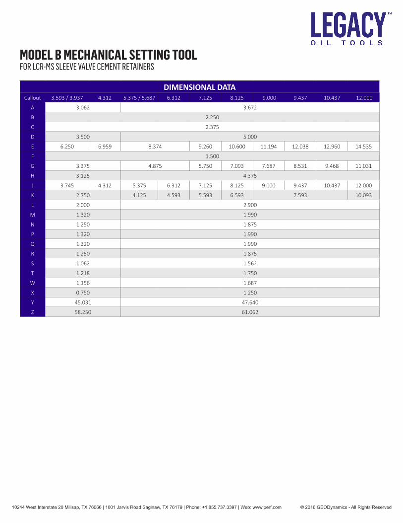
DIMENSIONAL DATACallout 3.593 / 3.937 4.312 5.375 / 5.687 6.312 7.125 8.125 9.000 9.437 10.437 12.000
A 3.062 3.672
B 2.250
C 2.375
D 3.500 5.000
E 6.250 6.959 8.374 9.260 10.600 11.194 12.038 12.960 14.535
F 1.500
G 3.375 4.875 5.750 7.093 7.687 8.531 9.468 11.031
H 3.125 4.375
J 3.745 4.312 5.375 6.312 7.125 8.125 9.000 9.437 10.437 12.000
K 2.750 4.125 4.593 5.593 6.593 7.593 10.093
L 2.000 2.900
M 1.320 1.990
N 1.250 1.875
P 1.320 1.990
Q 1.320 1.990
R 1.250 1.875
S 1.062 1.562
T 1.218 1.750
W 1.156 1.687
X 0.750 1.250
Y 45.031 47.640
Z 58.250 61.062
MODEL B MECHANICAL SETTING TOOLFOR LCR-MS SLEEVE VALVE CEMENT RETAINERS

FN
AB
CD
EG
HJ
KL
XW
T
S
RQ
PM
Z
Y
7/12
/201
6 3:
07:4
4 PM
ECN
NO
.***
FIN
ISH
WEI
GH
T
EAPP
**
(APP
RO
X. L
BS)
GEOD
ynam
ics, In
c.En
ginee
red P
erfo
ratin
g Solu
tions
ECN
NO
.
DR
AWIN
G S
TATU
SU
ND
ER R
EVIE
W
PRO
JEC
T N
UM
BER
C
D C B A
12
34
5
87
65
43
21
PRO
PRIE
TAR
Y AN
D C
ON
FID
ENTI
AL
MAT
ERIA
L
DR
AWN
ENG
APP
R.
DAT
EN
AME
SIZE BD
WG
NO
.R
EV
SHEE
T 1
OF
1
UN
LESS
OTH
ERW
ISE
SPEC
IFIE
D:
017-
3593
-000
MST
pg
2
B A
87
6
SCAL
E: 1
:8
GES
-RT-
001
TRAC
EABI
LITY
IND
ICAT
ED B
Y AC
CEP
TAN
CE
OF
THIS
DO
CU
MEN
T
3. A
LL D
IMEN
SIO
NS
IN IN
CH
ES
4. A
LL T
HR
EAD
S TO
BE
POLI
SHED
5. T
OLE
RAN
CES
:
EDG
ES 1
/64
R, A
LL C
OR
NER
RAD
II TO
.02
MAX
.SU
RFA
CES
SM
OO
TH T
O 6
3 M
ICR
ON
, BR
EAK
ALL
DIA
MET
ERS
CO
NC
TO
.005
TIR
, ALL
EXT
ERIO
RX.
X ±
0.0
30X.
XX ±
0.0
10D
ECIM
AL X
.XXX
± 0
.005
FRAC
TIO
NAL
± 1
/64
ANG
ULA
R ±
1/2
°
1. R
EMO
VE A
LL B
UR
RS
AND
SH
ARP
EDG
ES
2. A
LL M
ATER
IAL
AND
CO
ATIN
G C
ERTI
FIC
ATIO
NS
AR
E D
UE
ON
DEL
IVER
Y O
F M
ACH
INE
PAR
TS
THIS
DO
CU
MEN
T AN
D A
LL A
CC
OM
PAN
YIN
G IN
FOR
MAT
ION
ISTH
E C
ON
FID
ENTI
AL P
RO
PER
TY O
F G
EOD
YNAM
ICS
INC
.IT
MAY
NO
T BE
CO
PIED
, REC
OPI
ED,
REP
RO
DU
CED
, TR
ANSM
ITTE
D, O
R D
ISC
LOSE
D T
O O
THER
SW
ITH
OU
T EX
PRES
S PE
RM
ISSI
ON
AN
D IS
TO
BE
RET
UR
NED
UPO
N R
EQU
EST.
ALL
RIG
HTS
IN P
RO
PRIE
TAR
Y, C
OPY
RIG
HT
AND
NO
VEL
FEAT
UR
ES O
F TH
E SU
BJEC
T M
ATTE
R A
RE
EXPR
ESSL
Y R
ESER
VED
BY
GEO
DYN
AMIC
S IN
C.
REC
IPIE
NTS
AG
REE
EMEN
T TO
TH
E FO
REG
OIN
G IS
D

© 2016 GEODynamics - All Rights Reserved10244 West Interstate 20 Millsap, TX 76066 | 1001 Jarvis Road Saginaw, TX 76179 | Phone: +1.855.737.3397 | Web: www.perf.com
SUGGESTED DRILLING TECHNIQUES FOR LEGACY™ OIL TOOLSSLEEVE VALVE RETAINERS AND BRIDGE PLUGS
The following is a general guide for the most successful drill out technique:The tool should be run at a moderate speed avoiding sudden stops.
A. Bit – New, short tooth medium hard formation rock bit. If a mill is necessary, a concave face junk-mill should be used. A flat bottom mill is not suggested.
B. Rotary speed – 80 R.P.M. normal (120 R.P.M. as required).
C. Weight on bit – Apply 5,000 – 7,000 lbs. until the top end of the center body of retainer or plug is drilled away (3-5 inches for 4 1/2” thru 7” and 5-9 inches for 7 5/8” and larger tools). Additional weight can now be applied across the full bit diameter 2,000-3,000lb. per inch of bit diameter (i.e. 4 ½ bit use 9,000 – 13,500 lbs. of weight).
D. Drill Collars – Minimum of 8 for 4 1/2 thru 5 1/2 tools – 12 or more for 7” and larger tools.
Spudding the work string and variations in rotary speed and set down weight should be used to aid in breaking up large metal parts and preventing bit “tracking”. One or more junk baskets should be used above the bit when normal circulation is employed.

© 2016 GEODynamics - All Rights Reserved10244 West Interstate 20 Millsap, TX 76066 | 1001 Jarvis Road Saginaw, TX 76179 | Phone: +1.855.737.3397 | Web: www.perf.com

© 2016 GEODynamics - All Rights Reserved10244 West Interstate 20 Millsap, TX 76066 | 1001 Jarvis Road Saginaw, TX 76179 | Phone: +1.855.737.3397 | Web: www.perf.com

© 2016 GEODynamics - All Rights Reserved10244 West Interstate 20 Millsap, TX 76066 | 1001 Jarvis Road Saginaw, TX 76179 | Phone: +1.855.737.3397 | Web: www.perf.com

© 2016 GEODynamics - All Rights Reserved10244 West Interstate 20 Millsap, TX 76066 | 1001 Jarvis Road Saginaw, TX 76179 | Phone: +1.855.737.3397 | Web: www.perf.com

© 2016 GEODynamics - All Rights Reserved10244 West Interstate 20 Millsap, TX 76066 | 1001 Jarvis Road Saginaw, TX 76179 | Phone: +1.855.737.3397 | Web: www.perf.com