TECHNICAL BULLETIN #6 The Cassette Housingfriction Delrin®-type plastic to allow the smoothest...
5
TECHNICAL BULLETIN #6 The Cassette Housing Terence O’KeIIy Magnetic recording tape has grown immensely popular because of the development of plastic cartridges and cassettes. Until tape was stored safely in a plastic case 1 that could be easily inserted into a recorder or playback unit, magnetic tape was only used by those confident enough in their manual dexterity to handle delicate ribbons of coated plastic film and to thread them around a maze of guides, lifters, and capstans. Cartridges and cassettes made it easy: the tape came threaded around guides built into the plastic housing. Although ease of handling was an obvious benefit of the new tape formats, a disadvantage was that the tape alignment and guidance formerly entrusted to hardened steel parts on open-reel machines was now left to the somewhat suspect plastic parts of the tape housings. The development of the unisette, elcaset, and domestic video cassettes provides some evidence that engineers did not put full confidence in plastic housings. In these formats the recording machine itself provides the tape alignment and guidance after it draws the tape from the shells and places it on the transport system of the deck. The audio cassette, however, has constantly been improved by refinements of the shell. New materials, new designs, and new manufacturing techniques have all contributed to making the internal guiding of the tape more exact, more uniform, and more reliable. The basic parts which constitute a precision cassette are: • 2 shell halves plus their windows • 2 lubricated foil sheets, often called slip sheets” • 2 hubs, each with an interlocking piece to attach the tape leader • 2 roller guides on lubricated stainless steel axle pins • 1 metal shield • 1 pressure pad • tape and 2 leaders (or a leader” and ‘trailer”) attached to the hubs The halves are joined either by four or five stainless steel screws or by sonic welding. Either method can give a good seal. Five screws provide a more rigid fit than four screws, and sonic welding is even better in terms of rigid construction. The five-screw construction, however, is more popular because there is no risk of heat distortion due to welding and because it allows the user to take apart and reassemble the cassette with relative ease. Poor quality cassettes reveal themselves by missing parts or poorly formed parts, not by the method of sealing. Roller guides are usually the first parts to be eliminated in cheap cassettes. The roller guides are replaced by little plastic posts around which the tape is dragged but not guided. Sometimes the roller guide will be there, but the axle pin will be an ordinary steel pin. When this pin oxidizes and expands, the roller guide revolves irregularly and finally locks, becoming a
Transcript of TECHNICAL BULLETIN #6 The Cassette Housingfriction Delrin®-type plastic to allow the smoothest...

TECHNICAL BULLETIN #6
The Cassette Housing
Terence O’KeIIy
Magnetic recording tape has grown immensely popular because of the development of plastic cartridges and cassettes. Until tape was stored safely in a plastic case1 that could be easily inserted into a recorder or playback unit, magnetic tape was only used by those confident enough in their manual dexterity to handle delicate ribbons of coated plastic film and to thread them around a maze of guides, lifters, and capstans. Cartridges and cassettes made it easy: the tape came threaded around guides built into the plastic housing. Although ease of handling was an obvious benefit of the new tape formats, a disadvantage was that the tape alignment and guidance formerly entrusted to hardened steel parts on open-reel machines was now left to the somewhat suspect plastic parts of the tape housings. The development of the unisette, elcaset, and domestic video cassettes provides some evidence that engineers did not put full confidence in plastic housings. In these formats the recording machine itself provides the tape alignment and guidance after it draws the tape from the shells and places it on the transport system of the deck. The audio cassette, however, has constantly been improved by refinements of the shell. New materials, new designs, and new manufacturing techniques have all contributed to making the internal guiding of the tape more exact, more uniform, and more reliable. The basic parts which constitute a precision cassette are: • 2 shell halves plus their windows • 2 lubricated foil sheets, often called slip sheets” • 2 hubs, each with an interlocking piece to attach
the tape leader • 2 roller guides on lubricated stainless steel axle
pins • 1 metal shield • 1 pressure pad • tape and 2 leaders (or a leader” and ‘trailer”)
attached to the hubs
The halves are joined either by four or five stainless steel screws or by sonic welding. Either method can give a good seal. Five screws provide a more rigid fit than four screws, and sonic welding is even better in terms of rigid construction. The five-screw construction, however, is more popular because there is no risk of heat distortion due to welding and because it allows the user to take apart and reassemble the cassette with relative ease.
Poor quality cassettes reveal themselves by missing parts or poorly formed parts, not by the method of sealing. Roller guides are usually the first parts to be eliminated in cheap cassettes. The roller guides are replaced by little plastic posts around which the tape is dragged but not guided. Sometimes the roller guide will be there, but the axle pin will be an ordinary steel pin. When this pin oxidizes and expands, the roller guide revolves irregularly and finally locks, becoming a

big plastic post. The rusted pin and the sticking roller cannot guide the tape properly and will not give the smooth, flutter-free movement of a well designed guide. Cheap cassettes often eliminate the slip sheets, also. These sheets, made of a variety of plastic films with Teflon, silicone, or graphite lubrication, act as bearing surfaces for the hubs and as gentle guides for the tape packs. Without them, a cassette housing cannot provide uniform tape travel and cannot reduce tape edge damage. Although these sheets are often overlooked components of a cassette housing, they are critical in keeping wow and flutter to low levels because of the contact with the moving tape and hub. Manufacturers have experimented with various lubricants and folds in the sheets to keep wow and flutter effects as low as possible. Each part of the cassette is designed for a particular function. In order for it to perform properly, each part must be designed and manufactured properly. Sloppy parts assure sloppy performance. The function of the individual parts and important parameters are discussed below (cf. Fig. 1): 1. Metal shield The metal shield is a remnant of the early days of the cassette when players and recorders used high impedance heads and were likely to pick up noises from stray electromagnetic fields. Modern heads have lower impedances and are relatively immune to stray fields, but the shield is maintained in order to be compatible with old cassette machines. The material should be non-magnetic with good permeability to draw fields away from the head. 2. Pressure Pad The pressure pad pushes the tape against the head in order to achieve good tape/head contact that is essential for high frequency response at slow cassette speeds. Pressure pads can be mounted on foam supports or on metal springs, which are less likely to lose their elasticity under different environmental conditions. The pad must be positioned accurately so that it contacts the wide variety of head shapes in use today; for example, discrete heads, combination heads, and sandwiched record and playback heads. The fiber nap of the pad must be very tight so that loose fibers do not work their way between the head and the tape to cause dropouts of the audio signal. The pressure exerted by the pad must be within specified limits; too little pressure prevents good contact, and too much deforms the tape. 3. Hubs The hubs are usually a low-friction, Delrin® -type plastic. Concentricity is essential to provide smooth
tape movement. Concentricity must also be maintained at the point of the attachment of the leader to the hub. Much has been made of special C-clamp attachments whose shape matches that of the hub, but the C-clamp is merely a rounded version of a very old style of clamp. Another method uses a staking pin designed to fit inside the perimeter of the hub. Both clamps are just as effective as long as neither clamp interferes with the roundness of the tape pack by protruding from the hub, allowing the end of the leader to protrude from the hub, or by leaving too large a gap in its fitting. The thick leader ribbon that forms the first wrap around the hub defines the effective concentricity, not the style of the clamp. The hubs have a certain amount of play in the shell because they adapt to the feed and take-up shafts of the machines in which they are placed. Bearing surfaces in contact with the shell halves must be free of burrs and surface imperfections to insure smooth and wobble-free movement. 4. Leader The leader is a polyester (PET or polyethylene terephalate) film that is identical to by thicker than that used as backing for the tape in order for the leader to withstand the shock of sudden tension when the tape runs to the hub attachment in fast wind modes. Some leaders are designed as ‘non-abrasive head cleaners” that work by using their roughened surface to scrape debris off the head. This method is “non-abrasive” only in the sense that it is mercifully short. Head cleaning leader also happens to work in the wrong direction. Debris should be wiped out of the head gap, not scraped into it. The proper way to clean a head is use a cleaning solvent designed for heads2 and to apply it to the head with a swab in a motion parallel to the tape gaps, not in the direction of tape movement. The roughened surface of some leaders, however, does have an advantage for highly polished tapes in that it does not stick to heads or guides as pulls the tape through deck transport. A sudden change in the coefficient of friction from a smooth leader to a highly polished tape surface can cause a slight jump in tape movement that can lead to edge damage in some transports. 5. Roller Guides The guides are very critical for proper alignment, especially in double-capstan drive systems. Their axle pins must be wobble-free and aligned 90° to the plane of tape travel in order to avoid shifting the tape across the heads (Fig. 2). The guide itself should be perfectly concentric. Its shaft should have a slight bulge to it with the widest part exactly in the middle of the tape path. The molding technique must be such that no

seam or burr exists anywhere on the guide. The ends of the guide have flanges with very sharp delineation for the best tape contact. The roller is usually low- friction Delrin® -type plastic to allow the smoothest rotation on the axle pins.
6. Shell Halves. The shell halves are the most visible parts of the cassette, but many of their important design points are within the housing and not obvious. The plastic molding should have good definition and few flow marks for reasons of cosmetics; the individual parts should be aligned with extreme precision for reasons of
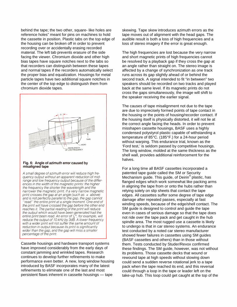
performance. Critical points are: the faces and edges of the cassette that are the support points used by various cassette machines for holding the cassette (Fig. 3); the hub support area; the fittings for the roller guide axles; and the plastic bridges” and pins in the open area where the head and capstan/pinch roller penetrate (Figs. 4 & 5). These last parts are extremely important because the head pushes the tape against
them after they have left the roller guide; if they are not properly aligned vertically, they can tilt the tape slightly in one direction or the other and cause errors in azimuth alignment (Fig. 6). Neither accurate roller guides nor dual-capstan control can make up for this kind of azimuth error because neither can isolate the tape from an off-center tilt.
The cassette housing has three rectangular openings meant for the erase head to the left, the playback head in the center, and the pinch roller to the right. Two circular holes on the face allow the capstan(s) to fit
behind the tape; the two other, square- like holes are reference holes” meant for pins on machines to hold the cassette in position. Plastic tabs on the top edge of the housing can be broken off in order to prevent recording over or accidentally erasing recorded material. The left tab prevents erasure of the side facing the viewer. Chromium dioxide and other high bias tapes have square notches next to the tabs so that recorders can distinguish between these tapes and normal tapes if the recorders automatically select the proper bias and equalization. Housings for metal particle tapes have two additional square notches in the center of the top edge to distinguish them from chromium dioxide tapes.
Cassette housings and hardware transport systems have improved considerably from the early days of constant jamming and wrinkled tapes. Research continues to develop further refinements to make performance even better. A new, long window housing introduced by BASF incorporates many of the latest refinements to eliminate one of the last and most persistent flaws inherent in cassette housings — tape
skewing. Tape skew introduces azimuth errors as the tape moves out of alignment with the head gaps. The audible result is both a loss of high frequencies and a loss of stereo imagery if the error is great enough. The high frequencies are lost because the very narrow and short magnetic prints of high frequencies cannot be resolved by a playback gap if they cross the gap at an angle rather than straight on. The stereo image is affected by a change of synchronization as one track runs across its gap slightly ahead of or behind the second track. A signal intended to fit “in between” two speakers should be recorded on two tracks and played back at the same level. If its magnetic prints do not cross the gaps simultaneously, the image will shift to the speaker receiving the earlier signal. The causes of tape misalignment not due to the tape are due to imprecisely formed points of tape contact in the housing or the points of housing/recorder contact. If the housing itself is physically distorted, it will not lie at the correct angle facing the heads. In order to prevent misshapen cassette housings, BASF uses a highly condensed polystyrol plastic capable of withstanding a temperature of 85°C. (185°F.) for a 24-hour period without warping. This endurance trial, known as the ‘Ford test,’ is seldom passed by competitive housings. The long window, molded at the same thickness as the shell wall, provides additional reinforcement for the halves. For a long time all BASF cassettes incorporated a patented tape guide called the SM or Security Mechanism guide. This guide, of Deirin® plastic, has flanged edges which work somewhat like packing arms in aligning the tape from or onto the hubs rather than relying solely on slip sheets that contact the tape edges. All cassettes suffer some degree of tape edge damage after repeated passes, especially at fast winding speeds, because of the edge/shell contact. The SM guide is designed to control and guide the tape even in cases of serious damage so that the tape does not ride over the tape pack and get caught in the hub spindle area. The most rugged use a cassette is likely to undergo is that in car stereo systems. An endurance test conducted by a noted car stereo manufacturer showed fewer failures in cassettes using SM guides (BASF cassettes and others) than in those without them. Tests conducted by Studer/Revox confirmed these findings. The SM guide, however, was not without its problems. Those cassette decks that wound or rewound tape at high speeds without slowing down could send a sudden reverse rotational jerk to a tape pack when the tape reached its end, and this reversal could through a loop in the tape or leader left on the take-up hub. This loop could get caught at the top of the

SM tusk and cause a tape jam in the very device meant to preclude jams. For this reason BASF eliminated the Security Mechanism and relied on other methods to prevent jamming. Molding techniques for the new long window design have been given the utmost care in the areas of tape/ shell contact. The roller axles, the bridges, the plastic guide pins, and the pressure pad stops are molded at extremely precise angles to maintain correct tape travel without causing the tape to skew. The most significant feature, however, is the shell half design. Manufacturers’ attempts to make mirror-image halves in order to achieve perfect tape alignment have not taken into account the fact that all internal parts involved in tape guidance, such as the roller guides and roller axles, would also have to be mirrored by an exact opposite. If one roller guide faces downward, the other would have to face upward. In addition, each tape contact point would have to be mirrored by its exact opposite, exact in every dimension, angle, and surface characteristic. Tape travel on side 1 of a mirror-image design cannot match that of side 2 if there is any difference at all between halves. The slightest difference between halves will cause the tape to track differently on both sides
BASF has developed a different design that totally avoids any mirror-image mismatch: all the tape contact points are on side 1 as a base, and side 2 provides the cover. The cover fits tightly on the base with an off-center joint at the area of tape travel so that the tape touches no parts of the seam. Any mismatch between halves, no matter how slight, will not affect the tape travel since that depends on one solid piece, not two. The angle of travel from side 1 is much more likely to match that of side 2 if the elements of error have been cut in half. The improvement in tape guidance is significant. Cassette tape has seen major improvements in increasing high frequency output; but unless that output is maintained in a stable manner, the increase will be of little practical value. The long window design of the new BASF housing is an important step in tape guidance and in freeing the cassette from what was once called an inherent limitation.
1 The word “cassette” is diminutive form of case, which is a derivative of the Latin casa, or ‘‘house.’’ A cassette is a ‘‘little house.’’
2 Freon TF or cleaners with a fluorocarbon base (trichlorotrifluorothane blended with 1,1,1 trichloroethane for a tongue twisting example) are safe and effective. Pure isopropyl alcohol is a little less effective, but also less expensive. Rubbing alcohol is often isopropyl alcohol with such additives as lanolin to prevent dried skin and may leave the additives on the heads as residue.