Technical Booklet R - Building Control NI · 8 Acce sstoand useofbuildings Technical Bo okletR:...
79
Access to and use of buildings Technical Booklet R October 2012 Finance and Personnel Department of www.dfpni.gov.uk Building Regulations (Northern Ireland) 2012 Guidance
Transcript of Technical Booklet R - Building Control NI · 8 Acce sstoand useofbuildings Technical Bo okletR:...

Access to and use of buildings
Techn i c a lBook le t R
October 2012
Finance andPersonnel
Department of
www.dfpni.gov.uk
Building Regulations (Northern Ireland) 2012
Gu i d ance

1
page
Introduct ion 4
Technical Booklets 4
This Technical Booklet 4
Protected buildings 5
Other legislation 5
Part R Regul ations 6
Guidance - Perfo rman ce and int roduction to provisions 8
Sect ion 1 General
Definitions 10
The principles of inclusive design within the built environment 11
Buildings other than dwellings 12
Dwellings 13
Visual contrast 13
Access statements 14
Buildi ngs other than dwelli ngs: Sect ion 2 to Section 6
Sect ion 2 Access to build ing s other than dwellin gs
General 16
Approach to buildings 16
Level approach 17
Hazards on access routes 19
Section 3 Access into bui ldi ngs other than dwellings
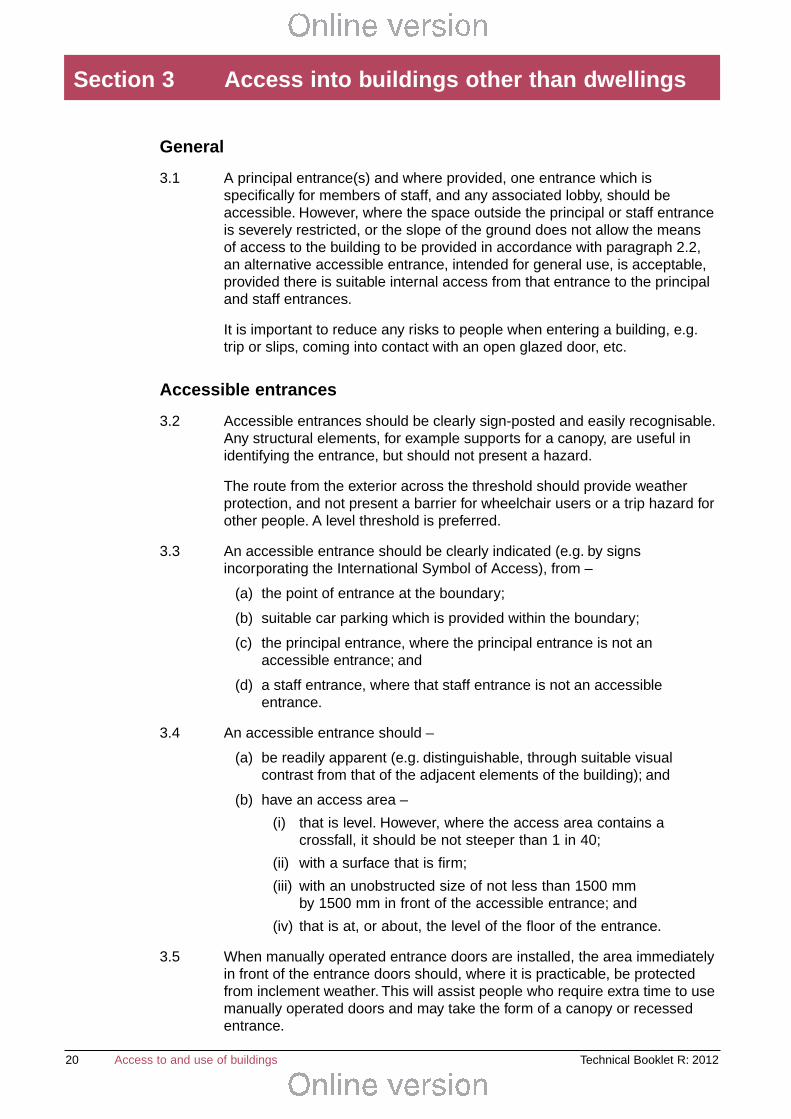
General 20
Accessible entrances 20
Doorways to accessible entrances 21
Technical Booklet R: 2012 Access to and use of buildings
Conte nts

2
Manually operated entrance doors to accessible entrances 22
Power operated entrance doors to accessible entrances 23
Glazed entrance doors and glazed screens to accessible entrances 25
Entrance lobbies to accessible entrances 25
Sect ion 4 Access wi th in buil din gs other than dwellings
Horizontal circulation 27
Corridors and passageways 27
Internal lobbies 28
Internal doors 28
Vertical circulation 31
Vertical access between storeys 31
Lifting devices 31
Passenger lifts 32
Lifting Platforms 34
Sect ion 5 Facili ties in build ings other than dwellings
General 35
Reception 35
Audience seating 36
Refreshment facilities 39
Guest bedrooms 41
Wheelchair accessible changing facilities 44
Outlets, switches and controls 46
Aids to communication 49
Sect ion 6 Sani tary accommodation and associated sanitary facilit ies inbui ldings other than dwel lings
General 50
Sanitary accommodation 51
Wheelchair accessible unisex sanitary accommodation 56
Traditional separate sex sanitary accommodation 57
Shower and bath facilities 58
Technical Booklet R: 2012Access to and use of buildings

3Technical Booklet R: 2012 Access to and use of buildings
Dwell ings and blocks of dwel lin gs: Sections 7 to Section 11
Sect ion 7 Means of access to and into a dwelli ng
Access to the dwelling 66
External approach 67
Access into the dwelling 67
Sect ion 8 Circu lat ion wi th in a dwelling
General 69
Horizontal circulation 69
Vertical circulation 70
Sect ion 9 Circu lat ion wi th in common areas of a block of dwel lin gs
General 71
Horizontal circulation 71
Vertical circulation 71
Sect ion 10 Sanitary convenien ce in a dwellin g
General 73
Access to sanitary conveniences 73
Sect ion 11 Heights of socket outlets, switches, etc. in a dwelli ng
Heights of outlets and switches 75
Appendix A Informat ive – Facil ities for people with profo und and mult ipl elearning disab ili ties 76
Appendix B Publi cati ons referred to 77

4 Technical Booklet R: 2012Access to and use of buildings
Technical Boo klets
This Technical Booklet, which takes effect on 31st October 2012, is one of aseries that has been prepared by the Department of Finance and Personnel(the Department) for the purpose of providing practical guidance withrespect to the technical requirements of the Building Regulations (NorthernIreland) 2012 (the Building Regulations).
At the back of each Technical Booklet is a list of all the Technical Bookletsthat have been prepared and published by the Department for this purpose.
The guidance given in a Technical Booklet includes performance standardsand design provisions relating to compliance with specific aspects of theBuilding Regulations for the more common building situations.
If the guidance in a Technical Booklet is followed there will be a presumptionof compliance with the requirements of those Building Regulations coveredby that guidance. However, this presumption can be overturned, so simplyfollowing the guidance does not guarantee compliance. For example, if aparticular circumstance is not one of the more common building situationsthe design provisions given in the Technical Booklet may not be appropriate.
There are likely to be alter native ways of demonstr atin g compliancewith the relevant requirements of the Build ing Regulati ons oth er thanby fo llowing a desig n provisio n give n in a Technical Booklet. There istherefore no oblig ation to adopt any parti cul ar provisi on set out in aTechnical Boo klet, should you decid e to comply in some other way.However, you wil l have to demonstrate that your alternati ve soluti onmeets the relevant requir ements of the Build ing Regulations by thoseoth er means.
This Technical Booklet
Requirements
The guidance contained in this Technical Booklet relates only to therequirements of regulations 91, 92, 93 and 94. The work will also have tocomply with all other relevant requirements of the Building Regulations.
Mater ials and workmanship
Any building work which is subject to requirements imposed by Part A of theBuilding Regulations should be carried out in accordance with regulation 23of those regulations. Guidance on meeting these requirements for materialsand workmanship is given in Technical Booklet B which supports Part B.
The Building Regulations are made for specific purposes, primarily securingthe health, safety, welfare and convenience of people and for theconservation of fuel and power. Standards and technical approvals arerelevant guidance to the extent that they relate to these purposes. However,they may also address other aspects of performance such as serviceability,or aspects which although they relate to health and safety are not coveredby the Building Regulations.
Introduction

5Technical Booklet R: 2012 Access to and use of buildings
Named standard s
Where this Technical Booklet makes reference to a named standard, therelevant version of the standard is the one listed in Appendix B. However, ifthis version has been replaced or updated by the issuing standards body,the new version may be used as a source of guidance provided that itcontinues to address the relevant requirements of the Building Regulations.
Diagrams
The diagrams in this Technical Booklet supplement the text. They do notshow all the details of construction and are not intended to illustratecompliance with any other requirement of the Building Regulations. They arenot necessarily to scale and should not be used as working details.
Prot ected bui ldings
District councils have a duty to take account of the desirability to preservethe character of protected buildings when carrying out their functions underBuilding Regulations. Therefore, where work is to be carried out to aprotected building to comply with Part R or any other Part of the BuildingRegulations, special consideration may be given to the extent of such workfor compliance where it would unacceptably alter the character orappearance of the building. Protected buildings are defined in Article 3A(2)of the Building Regulations (Northern Ireland) Order 1979 (as amended).
Other legi slati on
The provisions of this Technical Booklet relate to the requirements ofBuilding Regulations and do not include measures which may be necessaryto meet the requirements of other legislation. Such other legislation mayoperate during the design or construction stages or when a building isbrought into use and can extend to cover aspects which are outside thescope of the Building Regulations.
The Workpl ace (Health, Safety and Welfare) Regulations (North ernIreland) 1993
The Workplace (Health, Safety and Welfare) Regulations (Northern Ireland)1993 (the Workplace Regulations) contain some requirements which affectbuilding design. The main requirements are now covered by the BuildingRegulations, but for further information see – The Workplace Regulationsand the Workplace Health, Safety and Welfare Approved Code of Practiceand Guidance published by TSO.
The Workplace Regulations apply to the common parts of flats and similarbuildings if people such as cleaners, wardens and caretakers are employedto work in these common parts.Where the requirements of the BuildingRegulations that are covered by Part R do not apply to dwellings, theprovisions may still be required in the situations described above in order tosatisfy the Workplace Regulations.

6 Technical Booklet R: 2012Access to and use of buildings
PART R
Access to anduseof buildings
Appl ication and interpretation
90.—(1) Subject to paragraphs(2), (3) and(4) this Partshall apply to any building or part ofa building.
(2) This Part shall not apply to—
(a) anygarageor outbuilding associatedwith a dwelling;
(b) any part of a building which is usedsolely to enable the building or any service orfi tting in thebuilding to be inspected,maintainedor repaired; and
(c) thealteration or extension of anexistingdwelling to which thisPartdid not apply whenthedwelling was erectedother than where the alteration or extension affectsa facilitysuitable for useby peoplewith an impairment of mobility, hearingor sight, in theexisting building.
(3) The requirements of regulation 92 shall not apply to—
(a) a dwelling; and
(b) any building that is being extendedwhere reasonableprovision for accessto theextension is provided throughthebuilding being extended.
(4) The requirements of regulation 93 shall not apply to—
(a) a dwelling; and
(b) an extensionto abuil dingwherethereis provisionfor suitable sanitary accommodationin the building being extended and all usersof the extensioncangain access to andusethat sanitary accommodation.
Part R (comprising regulations 90 to 94) of the Building Regulations, which sets out therequirements for access to and use of buildings, has been replicated below for theconvenience of the user of this Technical Booklet and is taken directly from the BuildingRegulations (Northern Ireland) 2012.
Any person who intends to demonstrate compliance with the Building Regulations byfollowing the guidance given in this Technical Booklet is advised to ensure that theregulations below, are current on the date when plans are deposited or notices given tothe district council.
As Part A (comprising regulations 1 to 21) of the Building Regulations sets out theinterpretation along with the procedural requirements relating to the application of theregulations, the Department advises that all Parts of the Building Regulations are readin conjunction with Part A of those regulations.
The Building Regulations (Northern Ireland) 2012 and any subsequent amendmentmay be viewed by following the links from the Department’s website at“www.buildingregulationsni.gov.uk”.
Part R Regulations

7Technical Booklet R: 2012 Access to and use of buildings
(5) In this Part—
“Dwelling” meansa houseor fl at;
“Entrance storey” in a dwelli ngmeans thestoreywhich contains theprincipal entrance forthe dwelling;
“I ndependentaccess”to a part of or extensionto a building meansa route of access to thatpart or extensionwhich doesnot requirethe user to passthroughany other part of thebuilding;
“Principal entrance”in relation to adwelling meanstheentranceavisitor (not famili arwiththe dwelling) will normally expect to useto enterit;
“ Principal storey” in a dwelling means the storey nearestto the entrance storey whichcontainsa habitable room,or if therearetwo such storeys equally near, either such storey;
“Sanitary accommodation” has themeaningassigned to it by regulation 84 in Part P; and
“Sanitary convenience” meansa water closetandwashbasin.
Access and use
91. Reasonableprovision shall bemadefor peopleto have access to, into, within andto usea buil ding andits facil i ties:
Provided that in a dwell ing this requirementshall be limited to theentrancestorey or, wherethat storey contains no habitable room, to theprincipal storey.
Access to extensions
92. Reasonable provisionshall bemadefor independentaccessto anextension to a buil ding.
Sanitary accommodation in extensions
93. Where sanitary accommodation is provided in a buil ding, reasonable provision shall bemade for theprovision of suitable sanitaryaccommodation in any extension to the building.
Sanitary conveniences in dwellings
94. In a dwelling a sanitary convenienceshall beprovided—
(a) in theentrance storey; or
(b) wherethe entrance storey contains no habitablerooms– in theprincipal storey.

8 Technical Booklet R: 2012Access to and use of buildings
Performance to sati sfy regulati ons 91, 92, 93 and 94 in Part R
0.1 It is the view of the Department that the requirements of Part R will be metby making reasonable provision to ensure that buildings are accessible andusable.
In buildings other than dwellings, people, regardless of ability, age or gender,should be able to gain access to, into and within buildings and use theirfacilities, as customers, visitors and people who work in them.
In dwellings, all visitors should be able to –
(a) get access to and into the dwelling;
(b) access and use habitable rooms within the principal storey; and
(c) access and use a sanitary convenience in the dwelling.
Making provisions to facilitate people with a disability who may visit adwelling is also expected to enable occupants with disabilities to cope betterwith reduced mobility and to “stay put” longer in their own homes. It is notexpected to facilitate fully independent living for all people with disabilities.
Bui ldin gs other than dwellin gs
Introducti on to provisions in Sect ion 2
0.2 The guidance in Section 2 is to ensure a suitable and convenient means ofaccess to a building for people from the boundary and from car parkingprovided on site.
Provisions are also given for uncontrolled carriageway crossings andavoiding hazards on access routes.
Introducti on to provisions in Sect ion 3
0.3 The guidance in Section 3 is to assist people to be able to identify thebuilding entrance and use it to enter the building easily, conveniently andwithout the risk of injury.
Introducti on to provisions in Sect ion 4
0.4 The guidance in Section 4 is to facilitate the movement of people within abuilding both within a storey (horizontal circulation) and between storeys(vertical circulation).
Introducti on to provisions in Sect ion 5
0.5 The guidance in Section 5 is to ensure that people have access to and useof all the facilities provided in a building.
Guidance - Perform ance and introd uction to provi sions

9Technical Booklet R: 2012 Access to and use of buildings
Introducti on to provisions in Sect ion 6
0.6 The guidance in Section 6 is to ensure that sanitary accommodation andassociated sanitary facilities provided in a building, are no less available forpeople with a disability than for non-disabled people. Appropriate solutionsto sanitary accommodation may vary depending on the size, scale, natureand intended use of the building.
Dwelli ngs
Introducti on to provisions in Sect ion 7
0.7 The guidance in Section 7 is to facilitate people with a range of abilities toapproach and gain access into a dwelling and to a common entrance of ablock of dwellings e.g. flats, from the boundary or the point of alighting froma vehicle on a driveway within the plot.
Introducti on to provisions in Sect ion 8
0.8 The guidance in Section 8 is to facilitate access into habitable rooms and toa sanitary convenience in the entrance storey or the principal storey of thedwelling.
Introducti on to provisions in Sect ion 9
0.9 In a block of dwellings e.g. flats, the guidance is to ensure reasonableprovision for people with a disability to visit occupants who live on anystorey.
Introducti on to provisions in Sect ion 10
0.10 The guidance in Section 10 is to provide a sanitary convenience which adisabled visitor to the dwelling may use. The sanitary convenience shouldnormally be located in the entrance storey.Where the entrance storeycontains no habitable rooms, a sanitary convenience should be provided inthe principal storey.
Introducti on to provisions in Sect ion 11
0.11 The guidance in Section 11 is to assist those people whose reach is limited,to use a dwelling more easily, by locating switches, sockets, etc. at suitableheights.

10 Technical Booklet R: 2012Access to and use of buildings
Definit ions
1.1 In this Technical Booklet the following definitions apply –
Acc ess – approach or entry.
Acc ess ibl e – suitable access to and usable by all people, regardless oftheir ability.
Dwelling – has the meaning assigned to it by regulation 90 in Part R of theBuilding Regulations.
Entran ce sto rey in a dwelling – has the meaning assigned to it byregulation 90 in Part R of the Building Regulations.
Boundary – the boundary of the land (excluding any abutting street, canalor river) on which the building is erected.
Flat – has the meaning assigned to it by regulation 2 in Part A of theBuilding Regulations.
Iso lator – a switch used to cut off the supply of electricity to an electricalappliance for maintenance purposes.
Incor porated changin g facility – an accessible changing facility containedwithin and open to the communal changing facility.
Incor porated shower facility – an accessible shower facility containedwithin and open to the communal shower facility.
Level approach – (with respect to the approach to a building) an accessroute that is predominately level, but may contain a gradient less steep than1 in 20 in the direction of travel.
Liftin g device – a passenger lift or a lifting platform.
Plot – the area within the boundary of the land on which the building iserected.
Plot gradient – the gradient measured along the route of travel between thepoint of entry and the floor level at –
(a) the principal or an alternative entrance to a dwelling; or
(b) the common entrance or an alternative entrance to a block ofdwellings.
Point of entry – the point at which a person visiting the building either –
(a) normally enters the plot; or
(b) alights from a vehicle within the plot.
Prin cip al entrance (in buildings other than a dwelling or a block ofdwellings) – the entrance a visitor or customer (not familiar with the building)would normally expect to use to enter it.
Sect ion 1 General

11Technical Booklet R: 2012 Access to and use of buildings
Principal entr ance (in relation to a dwelling) – has the meaning assigned toit by regulation 90 in Part R of the Building Regulations.
Principal entr ance sto rey – the storey or storeys where the principalentrance or entrances are located. If an alternative accessible entrance is tobe provided by virtue of paragraph 3.1 the storey containing that entrance isa principal entrance storey.
Principal stor ey in a dwelling – has the meaning assigned to it byregulation 90 in Part R of the Building Regulations.
Sanitary accommodatio n – has the meaning assigned to it by regulation84 in Part P of the Building Regulations.
Sanitary conven ience – has the meaning assigned to it by regulation 90 inPart R of the Building Regulations.
Suita ble – (with respect to means of access and facilities) designed for useby people regardless of their ability.
Surface width – the width of a stair or ramp, measured at the tread of aflight or the surface of a ramp, between any enclosing walls, strings,upstands, kerbs or guarding.
Terminal fi tting – a water outlet device providing water to a sanitaryappliance.
Usable (with respect to buildings and parts of buildings) – convenient forindependent use.
Wheelchair accessib le – suitable access to and usable by wheelchairusers.
The princip les of inclusi ve design within the built envi ronment
1.2 An inclusive environment is one that can be used by everyone, regardless ofage, gender or ability. Buildings designed to be inclusive should be safe,convenient, sustainable and usable by all people.
The scope of this Technical Booklet is to give provisions for genericsolutions to the more common building scenarios to enable people to –
(a) get access to a building;
(b) get into a building;
(c) move around all floors of a building; and
(d) get access to and use the facilities (toilets, changing rooms, showersetc.) that are provided in a building.
The methods and standards within this Technical Booklet relate, in the main,but not exclusively, to the provision of design features and sufficient space,to make it possible for people with disabilities to independently access anduse a building.

12 Technical Booklet R: 2012Access to and use of buildings
Bui ldin gs other than dwellin gs
1.3 The provisions for access to and use of a building are for the benefit ofpeople who are customers or visitors to the building or who work in it.
1.4 An extension should be treated in the same manner as a new building. Theextension should –
(a) be independently approached and entered from the boundary andfrom car parking within this boundary; or
(b) have suitable access provided through the building being extended.
Where sanitary accommodation is provided in a building that is beingextended –
(c) then suitable sanitary accommodation should be provided within theextension; or
(d) the existing sanitary accommodation should also be suitable andaccessible by the users of the extension.
1.5 When a building is altered the alterations must comply with therequirements of Regulation 91 in Part R. The building, including access to itfrom the boundary and from on site car parking, where provided, must beno less accessible after completion of the alterations than it was before thework was carried out.
1.6 When a building undergoes a material change of use so that it is used as ahotel or boarding house, an institution, a place of assembly or recreation, ora shop it should be treated in the same manner as a new building.
When a part of a building undergoes a material change of use so that it isused as a hotel or boarding house, an institution, a place of assembly orrecreation, or a shop it should –
(a) be independently approached and entered or have suitable accessprovided through the building; and
(b) have any sanitary accommodation that is provided for or in connectionwith that part accessible (from that part) and usable. If sanitaryaccommodation is not provided as part of any works in relation to thematerial change of use and if users of that part of the building haveuse of sanitary accommodation elsewhere in the building then peopleshould be able to gain access to, and use that sanitaryaccommodation.
1.7 Part R is limited to matters of access to, into, within, and use of a building. Itdoes not extend to means of escape for a person with a disability in theevent of fire, for which reference should be made to Part E (Fire safety).
This Technical Booklet, gives guidance on the strategy for access to andwithin a building other than a dwelling.When this strategy includes the useof ramps and/or stairs, such ramps or stairs must satisfy the relevantrequirements of Part H.

13Technical Booklet R: 2012 Access to and use of buildings
Dwelli ngs
1.8 The provisions for access and for facilities within dwellings are for thebenefit of people who are disabled who may visit the dwelling.
Where Part R applies, reasonable provision should be made –
(a) so that people with a disability can reach the principal entrance to thedwelling, or to a common entrance to a block of dwellings, from theboundary or from car parking within this boundary;
(b) for access for people with a disability into and within the entrancestorey or the principal storey of the dwelling and to access and useany facilities provided to comply with Part R; and
(c) for sanitary conveniences for use by people with a disability.
Part R does not extend to means of escape for people with a disability in theevent of fire, for which reference should be made to Part E (Fire safety).
Part H (Stairs, ramps, guarding and protection from impact) containsprovisions for the design of stairs and ramps.
This Technical Booklet, gives guidance on the strategy for access to andwithin a dwelling.When this strategy includes the use of ramps and/orstairs, such ramps or stairs must satisfy the relevant requirements of Part H.
Visual contr ast
1.9 Visual contrast is the perception of a difference visually between oneelement of a building and another by reference to their light reflectancevalues.
Light reflectance value (LRV) is the total quantity of visible light reflected bya surface at all wavelengths and directions when illuminated by a lightsource.
For people with adequate vision, differences in the nature or the intensity ofcolour provide adequate visual contrast. Unfortunately, this is not the casefor all people who are visually impaired. The main feature of a surface,which appears to be strongly correlated with the ability of visually impairedpeople to identify differences in colour, is the LRV. Differences in LRV canbe used to assess the degree of visual contrast between the surfaces ofelements such as handrails, doors, door furniture, key fittings/fixtures andsurrounding surfaces, etc.
The LRV scale runs from 0, which is a perfectly absorbing surface that couldbe assumed to be totally black, up to 100, which is a perfectly reflectivesurface that could be considered to be perfect white. Because of practicalinfluences in any application, black is always greater than 0 and white neverequals 100.
A difference in LRV of 30 points or more allows a degree of variability that isrequired to provide reasonable visual contrast.
For flat areas it is thought that LRV differences are less important betweentwo large areas, e.g. between a wall and floor, than between a small objecton a larger background surface, e.g. a light switch on a wall.

14 Technical Booklet R: 2012Access to and use of buildings
Access statemen ts
1.10 Access statements are not a requirement of the Building Regulations.
Applicants may wish to satisfy the requirements of Part R by adopting theguidance and provisions of Technical Booklet R. However, they couldchoose to follow the performance criteria given in paragraph 0.1 and offeralternative design solutions they believe comply with the reasonableprovision requirements of the relevant regulation. Evidence to support suchan alternative design approach might include –
(a) application of the recommendations in BS 8300 where these differfrom the provisions, or are not covered, in this Technical Booklet;
(b) results of current validated research;
(c) outcome of consultations with other parties (e.g. Northern IrelandEnvironment Agency, Access Officers, local Access Groups, etc.); and
(d) convincing arguments that an alternative solution will achieve thesame, a better, or a more convenient outcome.
An access statement setting out the rationale for the access strategy, couldbe useful in presenting the evidence of the design approach adopted.
In the case of extensions and material changes of use of buildings otherthan dwellings, and particularly in the case of protected buildings, such astatement will allow an applicant to identify any constraints imposed by theexisting structure and its immediate environment and to proposecompensatory measures where full access proves to be impracticable orunreasonable. This will allow for an explanation to be provided andassessed in situations where, for example, a less than fully accessibleaccess route is proposed to an extension, or to a building or part of abuilding subject to a material change of use.

15Technical Booklet R: 2012 Access to and use of buildings
Buildingsother thandwellings

16 Technical Booklet R: 2012Access to and use of buildings
General
2.1 As far as possible, the means of access from the point of entrance at theboundary and from car parking designated for people with a disability whichis provided within the boundary, to the principal entrance(s) and, whereprovided, a staff entrance, should be level. However where a difference inlevel is unavoidable due to site constraints, the approach may have agentle gradient over a long distance (for all or part/s of the approach), or itmay incorporate a number of shorter parts at a steeper gradient, with levelareas at intervals as rest points. Generally, gradients within the approachshould be as gentle as possible. An approach that contains one or all ofthese features is called a level approach.
It is recognised that a level approach is not attainable in all situations andtherefore, an access route containing a ramp, may be an appropriatesolution to suit the site topography.
It is also important that routes between buildings within a complex are alsoaccessible.
To reduce the danger of inadvertently walking into a vehicular access routethe approach to a building should be separate from any vehicular route andwhere possible, not sharing the same surface.
All access routes to principal, or alternative accessible, entrances should besurfaced so that people are able to travel along them easily, withoutexcessive effort and without the risk of tripping or falling.
Potential hazards e.g. from open windows, on or over access routes shouldalso be avoided.
App roach to buildings
2.2 The means of access to a building should be by a level approach complyingwith paragraph 2.8 to 2.12. However, where site constraints necessitate thatall or any part of the means of access to or between buildings, contains agradient of 1 in 20 or steeper, a ramped approach should be provided.
2.3 As ramps are not necessarily suitable and convenient for all people it isbeneficial to have steps as well as a ramp. For example, some people whocan walk but have restricted mobility find it more difficult to negotiate a rampthan a stair. In addition, adverse weather conditions increase the risk ofslipping on a ramp.
Where a ramped approach has a rise of 300 mm or more, it should alsohave complementary steps.
2.4 If the total rise of a ramped approach is too high, it can be unacceptablytiring for wheelchair users and some people with walking difficulties, even ifa number of rest landings are provided. Therefore, where the access routeto the building is, or contains a ramped approach having a total rise of morethan 2000 mm, an additional means of access suitable for all people,should also be provided, e.g. a suitable lifting device.
Sect ion 2 Access to building s other than dwell ings

17Technical Booklet R: 2012 Access to and use of buildings
2.5 Where the approach requires to be guarded, that guarding must comply withthe relevant requirements of Part H.
2.6 Where there is a complex of buildings within the boundary, a level approachshould be provided between buildings to which Part R applies.
2.7 The approach to a building should be separate from any vehicular route.
Level approach
2.8 A level approach should have –
(a) an unobstructed width of not less than 1500 mm. However, at a localobstruction the width may be reduced to 1000 mm, provided that thelength of the reduced width is not more than 6 m and the obstructionis protected by a suitable barrier; and
(b) clear headroom of not less than 2100 mm.
Where the level approach has a gradient steeper than 1 in 60 it should havehorizontal rest areas, not less than 1200 mm long and a rise of not morethan 500 mm between rest areas.
Where the level approach is more than 50 m in length it should havepassing places. These should be spaced at a distance of not more than50 m with a clear line of sight between consecutive passing places. Everypassing place should be not less than 1800 mm wide and not less than2000 mm long therefore, the width of the passing place may include thewidth of the level approach. A level approach with a surface width of1800 mm or more can accommodate non-vehicular traffic without the needfor passing places.
Where a level approach has a crossfall it should be not steeper than 1 in 40.
2.9 The surface of a level approach should –
(a) be firm;
(b) reduce the risk of slipping;
(c) have similar surface frictional characteristics along its length; and
(d) have an even surface finish.
2.10 Notwithstanding the provisions of paragraph 2.9(d) –
(a) where formless materials are used as surfacing, any undulationsshould be not more than 3 mm measured from a point below a1000 mm straight edge; and
(b) where paving units are used as surfacing material, any difference inlevel between the units at the joints, should be not more than 5 mm.
2.11 Where paving units are used as surfacing material and have –
(a) recessed filled joints, the joints should be not more than 10 mm wideand 5 mm deep; and
(b) unfilled joints, the joints should be not more than 5 mm wide.

18 Technical Booklet R: 2012Access to and use of buildings
2.12 Where a level approach crosses a carriageway at an uncontrolled crossingpoint, this should be identified by using buff coloured blister type tactilewarning paving, having a length of not less than 1200 mm and a widthof 800 mm. See Diagram 2.1.
Blister surface
16 mm radius
25 mm diameter
5 mm
10 mm
Carriag eway crossing
profile of blisterblister tile unit
gradient not steeperthan 1 in 12
blister surface
dropped kerb flushwith carriageway
800 mm
not less than 1200 mm
level approach
carriageway
see para 2.12
Diagram 2.1 Uncon trolled carriageway cro ssi ngs

19Technical Booklet R: 2012 Access to and use of buildings
Hazards on access routes
Generally
2.13 Features of a building that occasionally obstruct an access route,particularly if they are partially transparent and therefore indistinct, or causea danger overhead, should not present a hazard to building users.
Protect ion from hazards
2.14 To reduce hazards on an access route for people including those who arevisually impaired, any –
(a) door (other than for emergency use only) which opens outwards;
(b) part of a window, when open in normal use, that projects more than100 mm; and
(c) other feature of a building which projects,
into an access route, should be protected by a distinguishable barrier railwhich incorporates either a vertically continuous barrier or a kerb at groundlevel. See Diagram 2.2.
2.15 Any area below the soffit of a stair or a ramp and its landings that is lessthan 2100 mm above an access route should be protected by adistinguishable barrier rail which incorporates either a vertically continuousbarrier or a kerb at ground level.
Plan
distinguishable barrier rail and kerb or barrier railand vertically continuous barrier
see paras 2.14 and 4.9
Sections
where there is a projection of not more than 100 mm into the approach no hazard protection is required
barrier rail and kerb
not less than 1100 mm
not less than 1100 mm
limit ofprojectionlimit of
projection
not more than100 mm
barrier railand vertically continuous barrier
Diagram 2.2 Hazards on access routes
20 Technical Booklet R: 2012Access to and use of buildings
General
3.1 A principal entrance(s) and where provided, one entrance which isspecifically for members of staff, and any associated lobby, should beaccessible. However, where the space outside the principal or staff entranceis severely restricted, or the slope of the ground does not allow the meansof access to the building to be provided in accordance with paragraph 2.2,an alternative accessible entrance, intended for general use, is acceptable,provided there is suitable internal access from that entrance to the principaland staff entrances.
It is important to reduce any risks to people when entering a building, e.g.trip or slips, coming into contact with an open glazed door, etc.
Accessi ble entrances
3.2 Accessible entrances should be clearly sign-posted and easily recognisable.Any structural elements, for example supports for a canopy, are useful inidentifying the entrance, but should not present a hazard.
The route from the exterior across the threshold should provide weatherprotection, and not present a barrier for wheelchair users or a trip hazard forother people. A level threshold is preferred.
3.3 An accessible entrance should be clearly indicated (e.g. by signsincorporating the International Symbol of Access), from –
(a) the point of entrance at the boundary;
(b) suitable car parking which is provided within the boundary;
(c) the principal entrance, where the principal entrance is not anaccessible entrance; and
(d) a staff entrance, where that staff entrance is not an accessibleentrance.
3.4 An accessible entrance should –
(a) be readily apparent (e.g. distinguishable, through suitable visualcontrast from that of the adjacent elements of the building); and
(b) have an access area –
(i) that is level. However, where the access area contains acrossfall, it should be not steeper than 1 in 40;
(ii) with a surface that is firm;
(iii) with an unobstructed size of not less than 1500 mmby 1500 mm in front of the accessible entrance; and
(iv) that is at, or about, the level of the floor of the entrance.
3.5 When manually operated entrance doors are installed, the area immediatelyin front of the entrance doors should, where it is practicable, be protectedfrom inclement weather. This will assist people who require extra time to usemanually operated doors and may take the form of a canopy or recessedentrance.
Sect ion 3 Access into buildings other than dwellings

21Technical Booklet R: 2012 Access to and use of buildings
3.6 Where an entrance communication system is installed, it should have bothvideo and audio communication to assist people with hearing loss or peoplewho cannot speak.
3.7 A floor immediately inside any accessible entrance should –
(a) have a surface which is firm and even;
(b) where there are changes in flooring surface, be at, or about, the levelof any adjacent flooring surface; and
(c) have a surface that will reduce the risk of tracking moisture into thebuilding (e.g. from shoes or wheelchair wheels). However, thisprovision is not required where the external access area is designedand constructed to limit the tracking of moisture into the building.
Doorw ays to accessibl e entrances
3.8 Doors to the principal entrance or alternative accessible entrance should beaccessible to all, particularly wheelchair users and people with limitedphysical dexterity. Entrance doors may be manually operated withoutpowered assistance, or power operated under manual or automatic control.
Once open, all doors to accessible entrances should be wide enough toallow unrestricted passage for a variety of users, including wheelchair users,people carrying luggage, people with assistance dogs, and people withpushchairs and small children.
3.9 An accessible entrance doorway should contain a leaf which provides aneffective clear width of not less than that given in column (2) of Table 3.1.This effective clear width applies to a single leaf door or one leaf of a doubleleaf door. However, where a double leaf door is power operated, theeffective clear width may be incorporated between both leaves providedthose leaves operate simultaneously.
Where a building is to be altered or undergo a material change of use andthe effective clear width given in column (2) of Table 3.1 cannot be achieved,an accessible entrance doorway may contain a leaf which provides aneffective clear width of not less than that given in column (3) of Table 3.1.
The effective clear width of a doorway should be measured in accordancewith Diagram 3.1.
Table 3.1 Effective clear wid ths of doorways to accessi bleentran ces
Users of entrance Effective clear width ofdoorway in a new building
Effective clear width ofdoor way in an existing
building
(1) (2) (3)
limited to staff and visitors 800 mm 750 mm
members of the public 1000 mm 775 mm

22 Technical Booklet R: 2012Access to and use of buildings
3.10 An accessible entrance doorway should have a threshold which is level.However, where required due to site location (e.g. to prevent the ingress ofmoisture), a threshold may contain one or more upstands, provided thecumulative height of these upstands is not more than 15 mm. An upstandmore than 5 mm high should have all exposed edges chamfered orrounded.
The route from the access area across the threshold should not present abarrier for wheelchair users or a trip hazard for other people.
3.11 A door to an accessible entrance should not project, when open, into anadjacent access route, unless that portion of the door which projects intothe access route is protected by a suitable barrier.
Manually oper ated entrance doors to accessi ble entrances
3.12 Self-closing devices on manually operated non-powered swing doors cancreate difficulties for many people who have limited upper body strength,are pushing prams or are carrying heavy objects.The force needed to opena door and pass through the doorway, against a closing device, shouldtherefore be limited.
A space alongside the leading edge of a door, on the pull side, will enable awheelchair user to reach and grip the door handle, then open the doorwithout releasing hold on the handle and without the footrest colliding withthe return wall.
Door furniture on manually operated non-powered doors should be easy tooperate by people with limited manual dexterity, and be readily apparent toassist visually impaired people.
effective clear width when door opens more than 90o
effective clear width when door opens to 90o
not less than 300 mm (unless door is power operated and activated in accordance with para 3.17) measured from the leading edge of the door to the return wall
see paras 3.9, 3.14 and 4.15
Note -single leaf doors and at least one leaf of a pair of doors should provide the effective clear width
Diagram 3.1 Measur ement of the effecti ve clear width of a doorway

23Technical Booklet R: 2012 Access to and use of buildings
3.13 The force required to open a manually operated entrance door should benot more than –
(a) 30 Newtons between 0º (door closed) and 30º of the opening arc ofthe door; and
(b) 22.5 Newtons from a point greater than 30º of the opening arc of thedoor,
measured at the leading edge of the door leaf during the opening action.See Diagram 3.2.
3.14 A manually operated entrance door should have an unobstructed space ofnot less than 300 mm, at the leading edge of the door leaf on the pull side.See Diagram 3.1.
3.15 Door opening furniture should –
(a) be distinguishable, through suitable visual contrast, from that of theface of the door leaf; and
(b) where the door leaf is fitted with a latch, be operable by a person withlimited manual dexterity (e.g. a lever handle).
Power operated entrance doo rs to accessi ble entrances
3.16 A powered door opening and closing system, either manually controlled orautomatically operated by sensors, is the most satisfactory solution for themajority of people. An automatic sliding door arrangement is particularlybeneficial as it avoids the risks associated with automatic swing doors andits use can make it possible to reduce the length of any entrance lobby.
Manual controls for powered entrance doors should be distinguishableagainst their background and located so that a person, having used thecontrol, does not need to move to avoid contact with the door as it opens.
not more than 30 Newtons
not more than 22.5 Newtons
see para 3.13
more than 30º
More than 30º0º (door closed) to 30º
Diagram 3.2 Measur ement of the opening forces of a door leaf

24 Technical Booklet R: 2012Access to and use of buildings
Revolving doors are not considered accessible. They create particulardifficulties, and risk of injury, for people with assistance dogs, visuallyimpaired people or those with mobility problems and for people with childrenand/or pushchairs. If the entrance includes a revolving door, then a doorcomplying with the provisions for manually operated or power operatedentrance doors should be provided immediately adjacent to it.
3.17 A power operated entrance door should have a sliding, swinging or foldingaction that is activated –
(a) manually by a push pad, electronic card, coded entry, or by remoteactivation; or
(b) automatically (e.g. by a motion detector).
3.18 Any manual controls to operate a powered entrance door should complywith the requirements of paragraph 5.40 and 5.44(g) (see Diagram 5.8(b)).
3.19 Where a power operated entrance door has a swing action, indication of itsoperation and direction of swing should be provided to the side that the dooropens towards.
3.20 Where a power operated entrance door has an automatic activation device,it should be positioned so that the edge of the detection zone, whereactivation is initiated, is 1400 mm from –
(a) the door, measured perpendicular to the plane of the closed door,when the door opens away from the user; and
(b) the leading edge of the door in the fully open position, when the dooropens towards the user.
See Diagram 3.3.
see para 3.20 edge of detection zone where door activation is initiated
edge of detection zone where door activation is initiated
barrier/hazard protection
detection zone
detection zone
1400 mm
1400 mm
1400 mm
Diagram 3.3 Detection zones for automati c acti vati on of powereddoor s

25Technical Booklet R: 2012 Access to and use of buildings
Glazed entrance doors and glazed screen s to accessi ble entrances
3.21 Visually impaired people should be in no doubt as to the location of glassentrance doors, especially when the doors are within a glazed screen.
The presence of the door should be apparent when it is shut and also whenopen.Where it can be held open, measures should be taken to avoid peoplebeing harmed by walking into the door.
In addition to meeting the requirements of Part R, glazed doors and screensmust also comply with the relevant requirements of Part V.
3.22 Where an entrance door is manufactured from transparent or translucentmaterials and –
(a) forms part of, or is adjacent to, a glazed screen, it should have its topand side face edges distinguishable, through suitable visual contrast,from that of the glazed screen; and
(b) is designed and installed to be capable of being held open, theleading edge of the door should be protected by a suitabledistinguishable barrier when in the held open position.
Entran ce lob bies to accessib le entran ces
3.23 An entrance lobby should be large enough and of a shape to allow awheelchair user along with a companion or a person pushing a pram tomove clear of one door before opening a second door. The minimum lengthof the lobby is related to door size, door swing, the projection of the doorinto the lobby and the size of an occupied wheelchair with a companionpushing.Where both doors of a lobby are automatic sliding doors, the lengthcan be reduced as no door swings are involved, nor is space required formanual operation. Similarly, if ‘reduced swing’ door sets are used, the lengthcan be reduced because the projection of the door into the lobby is reduced.
3.24 An entrance lobby should –
(a) have the minimum dimensions shown in Diagram 3.4, clear of anyprojections (including any handrail), into the lobby; and
(b) have a floor that complies with the provisions of paragraph 3.7.
3.25 Any door to and within any entrance lobby should comply with theprovisions of paragraphs 3.9 to 3.11, 3.13 to 3.15, 3.17 to 3.20 and 3.22.

26 Technical Booklet R: 2012Access to and use of buildings
Clear space to leading edge of door
For lobbies served by single leaf doors - the dimension "a" should be not less than 300 mm but for every 100 mm increase in this dimension (resulting in an increased lobby width) the overall length of the lobby "L" may be reduced by 100 mm but should not be less than L minus 600 mm.
Note -
Lobby widths
The unobstructed clear lobby width should be -
a) for lobbies served by single leaf doors - not less than the width of the widest door leaf plus 300 mm or not less than 1200 mm whichever is the greater; and
b) for lobbies served by double leaf doors - not less than 1800 mm.
1570 mm
not less than300 mm
1570 mm 1570 mm
projection ofdoor leaf 1 into lobby
projection ofdoor leaf 1 into lobby
projection ofdoor leaf 1 into lobby
not less than 300 mm
projection ofdoor leaf 1 into lobby
projection ofdoor leaf 2 into lobby
aa
not less than300 mm
not less than300 mm
aa
not less than300 mm
over
alll
engt
hof
lobb
y"L
"ov
eral
llen
gth
oflo
bby
"L"
over
alll
engt
hof
lobb
y"L
"
over
alll
engt
hof
lobb
y"L
"
over
alll
engt
hof
lobb
y"L
"a a
1570 mm
not less than300 mm
width of door leaf 2
width of door leaf 2
1570 mm
projection ofdoor leaf 2 into lobby
projection ofdoor leaf 2 into lobby
projection ofdoor leaf 2 into lobby
1570 mm
over
alll
engt
hof
lobb
y"L
"a
door leaf 2
door leaf 2
door leaf 2
door leaf 2
door leaf 2 door leaf 2
door leaf 2
door leaf 1
door leaf 1
door leaf 1 door leaf 1
door leaf 1 door leaf 1
door leaf 1
over
alll
engt
hof
lobb
y"L
"
projection ofdoor leaf 2 into lobby
1570 mm
Example 1 Example 2 Example 3
Example 4
Example 7
Example 5 Example 6
The required effective clear width of a door opening is dependent upon the width and direction of the approach.
see paras 3.24 and 4.11(a)
Diagram 3.4 Lobbies

27Technical Booklet R: 2012 Access to and use of buildings
General
4.1 In a building there should be sufficient space for manoeuvring, convenientways of travelling from one storey to another and the inclusion of features tohelp people move safely and conveniently through the building.
Horizontal circulation
Corri dors and passag eways
4.2 Corridors and passageways need to be wide enough to allow people withassistance dogs, buggies, people carrying cases, etc., to pass others on theaccess route.Wheelchair users should also have access to adjacent roomsand spaces, be able to pass other people and, where necessary, turnthrough 180°.
4.3 Horizontal circulation within a storey should be level or contain a gradient inthe direction of travel less steep than 1 in 20, or by means of a ramp orramps and landings.
Ramps are not necessarily suitable and convenient for all people. Forexample, some people who can walk but have restricted mobility find it moredifficult to negotiate a ramp than a stair. It is therefore beneficial to have astair as well as a ramp.
Where it is impracticable to provide a ramp to move between levels within astorey, a lifting platform, complying with the provisions of paragraphs 4.25to 4.33 and 4.39 to 4.45 should be provided to transfer wheelchair users orpeople with impaired mobility, vertically between levels. A stair shouldalways be provided, in addition to a lifting platform.
4.4 A corridor or passageway should have an unobstructed width of not lessthan 1200 mm. Minor projections (e.g. skirtings, architraves, etc.) may beignored. However, where a projection into the corridor or passageway isunavoidable (e.g. at an archway in an existing building) and is more than100 mm, that projection should have a suitable means of directing peoplearound it.
4.5 Where a corridor or passageway is more than 50 m in length and has anunobstructed width of less than 1800 mm, it should have passing placesspaced at not more than 50 m. Every passing place should be not lessthan 1800 mm wide and not less than 1800 mm long. The width of thepassing place may include the width of the corridor or passageway andmay be incorporated into corridor junctions.
4.6 The floor of a corridor or passageway should –
(a) have a surface that has a suitable slip resistance; and
(b) be level, or contain a gradient in the direction of travel less steep than1 in 20. However, where the floor has a gradient of 1 in 20 or steeper,a ramp or ramps and landings, should be provided.
Secti on 4 Access with in buildings other than dwellings

28 Technical Booklet R: 2012Access to and use of buildings
4.7 Where a corridor or passageway has a gradient –
(a) that is steeper than 1 in 60 but less steep than 1 in 20, itshould have –
(i) horizontal rest areas not less than 1500 mm long; and
(ii) a rise of not more than 500 mm between rest areas;
(b) the gradient should extend the full width of the corridor orpassageway or –
(i) have any exposed edge of the gradient distinguishable, throughsuitable visual contrast; and
(ii) be adequately guarded where there is a risk of falling.
4.8 A door should not open into a corridor or passageway, other than –
(a) a door to a cupboard or duct; or
(b) a door giving access to a unisex wheelchair accessible toilet, providedthat the corridor or passageway is not less than 1800 mm wide at thatpoint, and is not a main route of travel or a means of escape providedto comply with Part E.
4.9 Any area below the soffit of a stair or a ramp and its landings that is lessthan 2100 mm above a circulation route, should be protected by adistinguishable barrier rail which incorporates either a vertically continuousbarrier or a kerb at floor level. See Diagram 2.2. The provisions of thisparagraph should not apply to the headroom above a flight or ramp andlandings.
Internal lob bies
4.10 An internal lobby should allow a wheelchair user, with or without acompanion, or a person pushing a buggy, to move clear of one door beforeattempting to open a second door. The general guidance relating toentrance lobbies is applicable to internal lobbies.
4.11 An internal lobby should have –
(a) the minimum dimensions shown in Diagram 3.4, clear of anyprojections e.g. handrails, columns, ducts, etc.; and
(b) a floor surface that is at, or about, the same level as the floor surfaceat any entrance to the lobby.
Internal doo rs
4.12 For some building users doors are potential barriers. If doors are required,the use of self-closing devices should be minimised (particularly in parts ofbuildings used by the general public) since, as described in paragraph 3.12,they disadvantage many people who have limited upper body strength, arepushing prams or are carrying heavy objects.
Where closing devices are needed for fire control, electrically poweredhold-open devices or swing-free closing devices should be used asappropriate. Low energy powered door systems may be used in locationsnot subject to frequent use or heavy traffic as the opening and closingaction is relatively slow.

29Technical Booklet R: 2012 Access to and use of buildings
The presence of doors, whether open or closed, should be apparent tovisually impaired people through the careful choice of colour and materialfor the door and its surroundings. For example, when a door is open,partially sighted people should be able to identify the door opening withinthe wall, and the leading edge of the door.
Other guidance as set out in paragraph 3.12 in relation to manuallyoperated non-powered swing doors also applies.
Once open, doors should be wide enough to allow unrestricted passage fora variety of users, including wheelchair users.
4.13 The effective clear width of a doorway is interrelated to the width of thecirculation route and the direction of approach to the doorway.
An internal door should contain a leaf, which provides an effective clearwidth of not less than that given in column (3) of Table 4.1. This effectiveclear width applies to a single leaf door or one leaf of a double leaf door.However, where a double leaf door is power operated, the effective clearwidth may be incorporated between both leaves provided those leavesoperate simultaneously.
4.14 Where a building is to be altered or undergo a material change of use andthe provisions of paragraph 4.13 cannot be achieved, an internal door maycontain a leaf which provides an effective clear width of not less than thatgiven in column (4) of Table 4.1.
4.15 When an internal door is designed and constructed to be manually operatedit should –
(a) comply with the provisions of paragraph 3.13 in relation to openingforces;
(b) where the door is fitted with a latch, have door opening furniture that issuitable for use by a person with limited dexterity (e.g. a lever handle);and
(c) have an unobstructed space of not less than 300 mm at the leadingedge of the door on the pull side. See Diagram 3.1. This provisiondoes not apply to a door that gives access to a guest bedroom notdesigned as a wheelchair accessible bedroom.
Table 4.1 Effective clear width of in tern al doors
Widt h of cor ridor orpassageway
Directio n ofapproach
Effective clear widthof door in anew building
Effective clear widthof doo r in an
exist ing build ing
(1) (2) (3) (4)
not less than 1500 mm head on 800 mm 750 mm
not less than 1500 mm not head on 800 mm 750 mm
less than 1500 mm head on 800 mm 750 mm
less than 1500 mm not head on 825 mm 775 mm

30 Technical Booklet R: 2012Access to and use of buildings
4.16 Door opening furniture should be distinguishable, through suitable visualcontrast, from the face of the door leaf.
4.17 Any door surround should be distinguishable, through suitable visualcontrast, from the adjacent wall surface in which it is set.
4.18 An internal door that is designed and installed as to be capable of beingheld open, or where a door leaf is not self-closing, should have the leadingedge of the door leaf distinguishable, through suitable visual contrast, fromthe other surfaces of the door leaf.
4.19 Where a doorway contains door leaves of unequal width, and is across amain route of travel, or an escape route provided to comply with Part E, thewider door leaf should be located consistently on the same side throughoutthe length of the route.
4.20 Where a manually operated internal door is fitted with a self-closing deviceand –
(a) is across a corridor it should –
(i) comply with the provisions of paragraph 3.13 in relation toopening forces; or
(ii) be held open by a suitable device; and
(b) gives access to any part of a storey (e.g. rooms or similar spaces,other than those parts excluded by Regulation 90 in Part R) and is notacross a corridor it should –
(i) comply with the provisions of paragraph 3.13 in relation toopening forces; or
(ii) be fitted with a suitable closing device that will allow the door toswing free during normal operation.
4.21 As low effort powered door systems have an opening and closing action thatis relatively slow, where a door is fitted with a low effort powered swing dooropening system, the door should –
(a) not be across a main route of travel; and
(b) be capable of being opened in manual mode, power mode and powerassisted mode.

31Technical Booklet R: 2012 Access to and use of buildings
Vertical circulation
Vertical access between storeys
4.22 To facilitate all people, a passenger lift is the most suitable means of verticalaccess and should be provided wherever possible. However, given thespace constraints in some buildings, it may not always be possible to installthe type and size of passenger lift that would be suitable for use by all, andother options need to be considered to provide for users with mobilityimpairments.
The following provisions for a passenger lift or lifting platform relate to theprovision of sufficient space and design features that will make such liftingdevices accessible.
4.23 Whatever lifting device is chosen, internal stairs should also be provided asan alternative means of vertical access.
4.24 Vertical circulation to any storey above or below the principal entrancestorey should be provided by means of a passenger lift complying with theprovisions of paragraphs 4.25 to 4.38. However where –
(a) the space within a building is severely restricted by site constraints; or
(b) the installation of a passenger lift would severely affect –
(i) the existing accommodation; or
(ii) an existing accessible feature of the building,
a lifting platform, complying with the provisions of paragraphs 4.25 to 4.33and 4.39 to 4.45, may be provided to transfer, either independently or withtheir companions, wheelchair users or people with impaired mobilityvertically between storeys.
Lift ing devices
4.25 All users including wheelchair users should be able to reach and use thecontrols that summon and direct the lifting device.
4.26 A manoeuvring space in front of the door to the lifting device should beprovided on each storey. This space should have an unobstructed width anddepth of not less than 1500 mm.
4.27 Landing call buttons should –
(a) be not less than 900 mm or not more than 1100 mm above the floorlevel of the landing, and not less than 500 mm from any return wall;
(b) have suitable raised tactile indication of their function on, or adjacentto, the buttons to identify the storey and direction of travel; and
(c) be distinguishable, through suitable visual contrast, from anysurrounding face plate. The face plate should be distinguishable,through suitable visual contrast, from the surface on which it ismounted.

32 Technical Booklet R: 2012Access to and use of buildings
4.28 Lifting device control buttons should –
(a) have suitable raised tactile indication of their function, on, or adjacentto, the buttons within the lifting device; and
(b) be distinguishable, through suitable visual contrast, from anysurrounding face plate. The face plate should be distinguishable,through suitable visual contrast, from the surface on which it ismounted.
4.29 A handrail should be provided to at least one side of the car or platform ofthe lifting device. This will assist ambulant users.
The top surface of the handrail should be not less than 875 mm or not morethan 925 mm, above the floor of the lifting device.
4.30 A lifting device should have a suitable emergency communication system,giving audible and visual indication that the alarm has been given andreceived.
4.31 Any glazing to walls of the lifting device should be made readily apparent.
4.32 To reduce the risk of people slipping or falling, the surface of the floor of thelifting device and any associated manoeuvring space should have similarsurface frictional characteristics.
4.33 To aid visually impaired people, the floor of the lifting device should not beof a dark colour. A lift car with a dark coloured floor may, to a visuallyimpaired person, look like an open lift shaft.
Passenger lif ts
4.34 A wheelchair user needs sufficient space and time to enter and leave apassenger lift, particularly when sharing it with other people. Lift sizesshould therefore be chosen to suit the anticipated density of use of thebuilding and the needs of people with a disability. A lift car with a minimumsize of 1100 mm by 1400 mm accommodates a wheelchair user with anaccompanying person. A larger lift car size (2000 mm wide by 1400 mmdeep) will accommodate any type of wheelchair together with several otherpassengers. It will also allow a wheelchair user or a person with a walkingframe to turn through 180º.
Lift door systems should be designed to allow adequate time for people, andassistance dogs, to enter or leave the lift without coming into contact withclosing doors.
People using or waiting for a lift need audible and visual information toinform them that the lift car has arrived, and which floor it has reached.
4.35 The car of a passenger lift should have a width of not less than 1100 mmand a depth of not less than 1400 mm, measured internally.See Diagram 4.1.
Where the lift car is less than 1500 mm wide by 1500 mm deep, a suitablysized and positioned mirror should be fitted to the car wall opposite the door.This will assist a wheelchair user to exit the lift when it is of a size that willnot allow a wheelchair user to turn around within the lift car.

33Technical Booklet R: 2012 Access to and use of buildings
4.36 A passenger lift should have a power operated horizontal sliding door ordoors which provide a clear width of not less than 800 mm.See Diagram 4.1.
The door or doors to a passenger lift should be fitted with –
(a) an adjustable door timing device; and
(b) a door re-activating device, which prevents physical contact betweenthe user and the leading edge of the closing door or doors.
Lift door or doors should be distinguishable, through suitable visual contrast,from the adjacent landing, and internal car, wall surfaces.
4.37 The controls within the lift car should be located not less than 900 mm, andnot more than 1200 mm above the floor of the car, and not lessthan 400 mm horizontally from any return wall of the lift car.See Diagram 4.1.
4.38 Visual indication and voice indication of the lift arrival and its location,should be provided in the lift lobby and within the lift car.
Diagram 4.1 Passen ger lift
unobstructed manoeuvring space
top of handrail not less than 875 mm or not more than 925 mm above car floor level
visual and tactile indication of storey
lift call buttons withtactile identification
lift car controls withtactile indication
400 mm
800 mm
1100 mm
not less than1500 mm
not less than1500 mm
not less than1100 mm
not less than1400 mm
900 mm
zone for landingcall buttons
zone for lift car controls between 900 mm and 1200 mm above car floor level
see paras 4.35 to 4.37 and 9.8

34 Technical Booklet R: 2012Access to and use of buildings
Lif ting platf orms
4.39 A lifting platform should only be provided to transfer wheelchair users,people with reduced mobility and their companions vertically between levelsor storeys.
All users, including wheelchair users, should be able to reach and use thecontrols that summon and direct the lifting platform.
People using a lifting platform need audible and visual information to tellthem that the platform has arrived, and which floor it has reached.
4.40 A lifting platform should be contained within a liftway enclosure where –
(a) the vertical travel distance is more than 2000 mm; or
(b) the lifting platform travels through a floor penetration.
4.41 A lifting platform should have a platform size of –
(a) not less than 800 mm wide and not less than 1250 mm deep, wherethe lifting platform is not contained within a liftway enclosure;
(b) not less than 900 mm wide and not less than 1400 mm deep, wherethe lifting platform is contained within a liftway enclosure;
(c) not less than 1100 mm wide and not less than 1400 mm deep, wherethere are two lift doors located at 90o relative to each other; or
(d) not less than 1100 mm wide and not less than 1400 mm deep, wherethe lifting platform is designed and constructed to accommodate anaccompanied wheelchair user.
4.42 A lifting platform should have a door or doors which provide an effectiveclear width of not less than –
(a) 900 mm, where the size of the lifting platform is not less than1100 mm wide and not less than 1400 mm deep; or
(b) 800 mm in any other case.
A door or doors to a lifting platform should be distinguishable, throughsuitable visual contrast, from that of the adjacent wall surfaces.
4.43 The platform controls for a lifting platform should be –
(a) of the continuous pressure type; and
(b) positioned not less than 800 mm and not more than 1100 mm abovethe floor of the lifting platform and not less than 400 mm horizontallyfrom the front face of the lifting platform.
4.44 Visual indication and audible indication of the lifting platform arrival and thefloor reached, should be provided within the lifting platform.
4.45 Clear permanent operating instructions should be provided either in, oradjacent to, the lifting platform.

35Technical Booklet R: 2012 Access to and use of buildings
General
5.1 This Section gives guidance to ensure that people have access to facilitiesthat are provided in a building. Provisions for sanitary accommodation andassociated sanitary facilities are given in Section 6.
Recepti on
5.2 As the area inside the entrance (or associated lobby) is the first point ofcontact with a building’s activities and resources, consequently, thereception area in particular should be easily identifiable and also convenientto use.
Fixed recepti on counter
5.3 Where a fixed reception counter is provided in a space immediately insidethe principal entrance, accessible entrance or associated lobby, it should –
(a) be readily apparent from the entrance doors or entrance lobby;
(b) be located so as not to be subject to the risk of extraneous externalnoise; and
(c) have a means of access that complies with paragraphs 4.4 to 4.9.
5.4 At least one section of a reception counter should have –
(a) its working surface not more than 760 mm above floor level for alength of not less than 1500 mm;
(b) a knee space of not less than 500 mm deep by not less than 700 mmabove floor level; and
(c) a clear space 1200 mm deep by 1800 mm wide in front of the lowersection of the reception counter.
This section of the reception counter should be located in an obviousposition.
See Diagram 5.1.
see para 5.4
not less than 500 mm deepknee space
not less than 700 mm highknee space
counter not more than 760 mm high
not less than500 mm deepknee space
not less than 1500 mm
clear space in frontof reception counter1200 mm
1800 mm
lowered section of counter
Plan Sect ion
Diagr am 5.1 Receptio n counter
Secti on 5 Facilities in buildings other than dwel lings

36 Technical Booklet R: 2012Access to and use of buildings
Audi ence seati ng
5.5 Where permanent or removable seating is provided as part of the design,allowance should be made for people who have a disability to have a choiceof seating location at spectator events.Wheelchair users and those with amobility impairment should be provided with spaces into which they canmanoeuvre easily, and which offer them a clear view of the activity takingplace, while ensuring they are not segregated into special areas and notobstructing the view of other users.
Wheelchair users and people who have difficulty in using seats with fixedarms should have the choice of sitting next to a companion wheelchair useror a conventionally seated person.
5.6 Where there is fixed audience seating, wheelchair spaces should beprovided in accordance with Table 5.1.
5.7 A wheelchair space should –
(a) have a horizontal floor area; and
(b) be not less than 900 mm wide by 1400 mm deep.
5.8 Wheelchair spaces should be located –
(a) in a range of single and double wheelchair spaces, with a standardseat to at least one side of each space or group of spaces; and
(b) in such a way as to give a range of views.
See Diagrams 5.2, 5.3 and 5.4.
5.9 Any stepped gangway to stepped terrace audience seating, should have asuitable means of providing support to people who have physical difficultyin negotiating changes of level.
Table 5.1 Provisio n of wheelchair spaces in audience seatin g
Seatingcapacit y
Minim um provis ion ofwheelchair spaces
up to 600 1% of total seating capacity (or part thereof) to be permanentwheelchair spaces augmented by the provision of removableseating to create, in total, 6 wheelchair spaces
601 to 10,000 1% of total seating capacity (or part thereof) to be permanentwheelchair spaces
10,001 to 20,000 100, plus 5 per 1000 (or part thereof) above 10,000(all to be permanent wheelchair spaces)
20,001 to 40,000 150, plus 3 per 1000 (or part thereof) above 20,000(all to be permanent wheelchair spaces)
more than 40,000 210, plus 2 per 1000 (or part thereof) above 40,000(all to be permanent wheelchair spaces)
Example 1: A facility has an audience seating capacity of 2,350 therefore 1% of 2350 =23.5 rounded up to 24 wheelchair spaces.Example 2: A facility has an audience seating capacity of 28,500 therefore 150 spaces arerequired for the first 20,000, the remaining 8,500 is rounded up to 9,000 which requires 27spaces (3 per 1000). Therefore 177 wheelchair spaces must be provided.

37Technical Booklet R: 2012 Access to and use of buildings
5.10 Standard fixed seating at the ends of rows and those adjacent to wheelchairspaces should, where they have arm rests, have detachable or lift-up armrests. See Diagrams 5.3 and 5.4.
the dimension from the front of the wheelchair space to the rear of the access area shouldbe not less than 2000 mm when the area to the back of the wheelchair space gives access to a row of seats and where access is from one side only
wheelchair spaces created by removing seating
detachable orlift-up arm
detachable or lift-up arm
see paras 5.8 and 5.10
1400 mm
900
mm
Diagram 5.3 Examples of wheelch air spaces created by removabl eseati ng
entry and exit entry and exit
entry and exit
entry and exit
see para 5.8
Diagram 5.2 Typical arrangement of wheelchai r spaces

38 Technical Booklet R: 2012Access to and use of buildings
see paras 5.8 and 5.10
not less than 2300 mm from the front of the wheelchair space where the area to the back of the wheelchair space gives access to a corridor or passageway
passageway
detachable or lift-up arm
detachable or lift-up arm
passageway
detachable or lift-up arm
permanent wheelchair spacenot less than 1400 mm long by 900 mm wide
permanent wheelchair spacenot less than 1400 mm long by 900 mm wide
1400 mm
detachable or lift-up arm
Diagram 5.4 Examp les of permanent wheelchair spaces

39Technical Booklet R: 2012 Access to and use of buildings
Refresh ment faci li ties
5.11 Refreshment facilities, such as restaurants and bars, should be designed sothat they can be accessed and used by all people. All floor areas in arefreshment facility, even when located at different levels, should beaccessible, see paragraph 4.3.
Bars and counters (or sections of them) should be at a level suitable forwheelchair users. However, consideration should be given to the specificuse of the bar or counter and the interaction of the users with it.
5.12 In a refreshment facility e.g. a restaurant or a bar, people should haveaccess to and use of –
(a) the full range of services offered; and
(b) bar and self-service counters.
5.13 A serving counter or bar counter should have not less than one section ofits working surface at a height of 850 mm above floor level for a length ofnot less than 1500 mm.
5.14 A level threshold complying with the provisions of paragraph 3.10, shouldbe provided to any doorway between the refreshment facility in a buildingand any associated external seating area.
Shared ref reshme nt faci li ties
5.15 A shared self-catering refreshment facility e.g. a facility for tea making,should have –
(a) a work surface at 850 mm above floor level; and
(b) a clear knee space below the work surface –
(i) of not less than 700 mm above floor level; and
(ii) where appropriate, not less than 800 mm between floor units.
See Diagram 5.5.

40 Technical Booklet R: 2012Access to and use of buildings
see para 5.15
1500 mm by 1500 mmwheelchair turning space
clear knee space under worktop not less than 700 mm above floor level
clear knee space under worktop not less than 700 mm abovefloor level
work surface 850 mm above floor level
floor unit
floor unit
800 mm minimum clear kneespace between units
Example 1 - basic refreshment facility
Example 2 - sh owing clear knee space between floor units
1500 mm by 1500 mmwheelchair turning space
work surface 850 mm above floor level
floor unit
work surface 850 mm above floor level
shallow sink to maintainknee space
800 mm
800 mm
clear knee space
Diagram 5.5 Examp les of a shar ed refresh ment faci lity

41Technical Booklet R: 2012 Access to and use of buildings
Guest bedrooms
5.16 Sleeping accommodation, where provided for a significant number ofpeople, e.g. in hotels, motels, purpose built student living accommodation,etc., should be convenient for all.
All guest bedrooms
5.17 All guest bedrooms should include facilities that make them suitable forpeople who do not use a wheelchair, but may have mobility, sensory,dexterity or learning difficulties.
It is important to ensure that, in all bedrooms, built-in wardrobes andshelving are accessible and convenient to use.
5.18 Where door signage is provided to a guest bedroom, it should have suitabletactile indication of the room name or number.
5.19 Where an opening window is provided to a guest bedroom –
(a) the opening portion should be not less than 800 mm above floor level;and
(b) a control used for opening or closing a window should be –
(i) located not less than 800 mm and not more than 1000 mmabove floor level; and
(ii) designed and constructed for single handed use.
5.20 Where a fixed storage system has swing doors, these doors should becapable of opening through 180º.
5.21 Door furniture to fixed storage systems, within guest bedrooms, shouldbe –
(a) easy to grip and operate; and
(b) distinguishable, through suitable visual contrast, from the face of thedoor leaf.
5.22 All guest bedrooms should have a visual fire alarm signal in addition to therequirements of Part E.
Wheelchai r accessi ble guest bedrooms
5.23 As people who use wheelchairs require greater provision of space, aproportion of the guest bedrooms should be designed for independent useby wheelchair users.
Wheelchair accessible bedrooms should be no less advantageouslysituated than other bedrooms.
5.24 At least one guest bedroom out of every 20 (or part thereof) guestbedrooms should be wheelchair accessible.
Where there is more than one wheelchair accessible bedroom provided,they should be positioned within the building to give a range of locations.
A typical wheelchair accessible guest bedroom is shown in Diagram 5.6.

42 Technical Booklet R: 2012Access to and use of buildings
300 mm minimum
for details of accessible shower rooms and bathrooms see Section 6
clear opening width of doorway is relatedto the approach and passageway width
effective clear width of doorwayis related to the approach and passageway width
alarm pull cord
1500 mm x 1500 mmwheelchair turning space to transfer sideof bed
see para 5.24
Diagram 5.6 Typi cal wheelchair accessible guest bedroom

43Technical Booklet R: 2012 Access to and use of buildings
5.25 Where a wheelchair accessible guest bedroom has a balcony, there shouldbe access to it by a doorway –
(a) that has a clear opening width that complies with Table 4.1;
(b) with a level threshold that complies with the provisions ofparagraph 3.10; and
(c) with a clear space to the bedroom side of not less than 1500 mmdeep.
Where a door to a balcony contains glazing, it should have a zone ofvisibility from a height above floor level of not more than 900 mm to not lessthan 1200 mm.
5.26 Where a door viewer is provided to the entrance door to a wheelchairaccessible guest bedroom a second door viewer should also be provided.These door viewers should be positioned at 1050 mm and 1500 mm abovefloor level.
5.27 A wheelchair accessible guest bedroom should have an emergencyassistance alarm –
(a) that is activated by a pull cord, complying with the provisions ofparagraph 5.46, that can be operated from the bed and from theadjacent floor area at the transfer side of the bed;
(b) with a reset button, that can be operated from the bed and from theadjacent area at the transfer side of the bed;
(c) having a visual and an audible indication that the emergency alarmhas been activated; and
(d) having a visual and an audible call signal positioned immediatelyoutside the wheelchair accessible bedroom and at a centralmonitoring point.

44 Technical Booklet R: 2012Access to and use of buildings
Wheelchai r accessi ble changing facil it ies
5.28 In buildings where changing facilities are provided, some disabled peoplemay require the privacy and convenience of an individual self-containedcubicle or compartment. The self-contained cubicle or compartment shouldallow space for an assistant.
Provision of manoeuvring space for a wheelchair, to enable turning andtransfer onto the seat, and provision of mirrors and clothes hooks mountedat suitable heights, are all critical features in relation to independent orassisted use of changing facilities. It is important that the seat and grab railshave suitable structural fixing support.
5.29 A communal changing facility should have not less than one wheelchairaccessible incorporated changing facility. An incorporated changing facilityshould have the minimum dimensions and arrangement of fittings as shownin Diagram 5.7. A wheelchair accessible incorporated changing facility is notrequired to be separated by a door from the communal changing facility.
5.30 A building for sports facilities should have an individual wheelchairaccessible changing room. This is in addition to the provisions ofparagraph 5.29.
5.31 Where changing facilities are provided for general use and are notassociated with showering facilities (e.g. in a clothes shop), not less thanone individual wheelchair accessible changing room should be provided.See Diagram 5.7.
5.32 Where there is more than one individual wheelchair accessible changingfacility, a mixture of left and right hand transfer layouts should be providedto give the user a choice of transfer sides.
5.33 Every individual and incorporated wheelchair accessible changing facilityshould have –
(a) an emergency assistance alarm complying with the provisions ofparagraph 6.5; and
(b) an emergency assistance alarm pull cord complying with theprovisions of paragraph 5.46, that can be reached from the tip-upseat and the area adjacent to the seat.
5.34 A wheelchair accessible changing facility should have a clear space not lessthan 1500 mm deep in front of any fixed clothing storage system.
5.35 Where a door is provided to a wheelchair accessible changing facility, itshould be capable of being opened outwards, from the outside, in the caseof an emergency.
5.36 Where a fire alarm is provided within a wheelchair accessible changingfacility, it should emit both an audible and visual alarm signal.
5.37 A wheelchair accessible changing facility should, where it is associated witha shower facility, have –
(a) a floor with a surface that reduces the risk of slipping; and
(b) a fixed storage system for limb storage, for the benefit of amputees.
An individual wheelchair accessible changing facility is shown inDiagram 5.7.

45Technical Booklet R: 2012 Access to and use of buildings
alarmpull cord
towel rail where appropriate
towel rail where appropriate
clothes hooks at1400 mm and 1050 mm above floor level
vertical grab railnot less than 500 mm long
not less than 2100 mm unobstructed height
back rest
horizontalgrab rail
tip-up seat
alarm pull cord
Sectiondrop down railon side wall
drop down rail
drop down rails
clothes hooks
1500 mm by 1500 mmwheelchair turning space
tip-upseat
mirror
Plan
480 mm680 mm 800 mm
2200 mm
650 mm
500 mm
320 mm
250 mm
600 mm 300 mm
200 mm
50 mm
alarm reset
wheelchair accessible incorporated changingfacilities are not required to be separated by a door from the communal changing facilities
see paras 5.29, 5.31 and 5.37
grab rail
2000 mm
Note –
Diagram 5.7 Indiv idu al wheelchair accessib le changin g facil ity

46 Technical Booklet R: 2012Access to and use of buildings
Out lets, swit ches and contro ls
5.38 The key factors that affect the use of outlets, switches, and controls areease of operation, visibility, height and freedom from obstruction. However,there can be exceptions to height requirements for some outlets, e.g. thoseset into the floor.
Outlets, switches and controls that contrast visually with their surroundingsare more convenient for visually impaired people.
The location of socket outlets in relation to doorways and return wallsshould, where practicable, be consistent throughout the building to furtherreinforce the ease with which people manipulate switches and controls.
Light switches that are activated by a large push pad are also moreconvenient for visually impaired people to use.
All people who would reasonably expect to use a control should be able tolocate it, know which setting it is on and use it without inadvertentlychanging its setting.
5.39 Paragraphs 5.36 and 5.41 to 5.44 should not apply where the outlet, switchor control is required only for maintenance purposes or not intended foroperation by the users of the building.
An outlet, switch or control should not require the simultaneous use of twohands unless this mode of operation is required for reasons of safety.
5.40 An outlet, switch or control face plate should be distinguishable, throughsuitable visual contrast, from the background against which it is seen.
Outlets
5.41 An outlet for a non-permanently wired appliance e.g. socket outlet,telephone outlet, etc., should be located within horizontal reach and not lessthan 400 mm and not more than 1000 mm above the floor level.See Diagram 5.8(a)(1). However, the provisions of this paragraph shouldnot apply to any outlet that is set into a flush mounted floor box locatedwithin areas that are designed to be open plan.
5.42 Socket outlets should be located not less than 350 mm from any return wall.
Switches and controls
5.43 A switched outlet should clearly indicate when in the “on” position (e.g. by aneon indicator, or the top of the rocker is coloured red and exposed when inthe “on” position etc.).
5.44 A switch or control –
(a) should be located within horizontal reach;
(b) for a permanently wired appliance, should be located not lessthan 400 mm and not more than 1200 mm above floor level.See Diagram 5.8(a)(2). However, where the design of the appliancerequires the switch to be placed at a higher level then it should be notmore than 1400 mm above floor level;

47Technical Booklet R: 2012 Access to and use of buildings
(c) for artificial lighting, should be located not less than 900 mm and notmore than 1100 mm above floor level. See Diagram 5.8(a)(3).Wherethe switch is installed for the use of visitors or customers it should beof the large push pad type;
(d) that requires precise hand movement (e.g. a ventilation controller),should be located not less than 750 mm and not more than 1200 mmabove floor level. See Diagram 5.8(a)(4);
(e) that is operated using push buttons that require limited dexterity (e.g.door bell, entry phone, etc.), should be located not more than1200 mm above floor level. See Diagram 5.8(a)(5);
(f) that requires the user to read a display or setting (e.g. a thermostat),should be located not less than 1200 mm and not more than 1400 mmabove floor level. See Diagram 5.8(a)(6); and
(g) for a power operated door, should be located not less than 750 mmand not more than 1000 mm above floor level. See Diagram 5.8(b).
5.45 A light cord pull switch should have a 50 mm diameter bangle attached at aheight of not less than 900 mm and not more than 1100 mm above floorlevel. See Diagram 5.8(a)(3). The bangle should be distinguishable throughsuitable visual contrast, from the background against which it is seen.
Where a pull cord light switch is installed in a room or space that alsocontains an emergency assistance alarm both the pull cord and the bangleshould be distinguishable visually from any emergency assistance alarmpull cord.
5.46 An emergency assistance alarm should have a red coloured pull cord withtwo red coloured 50 mm diameter bangles. The lower bangle should be setat a height of 100 mm above floor level and the upper bangle should belocated not less than 800 mm and not more than 1000 mm above floor level.See Diagram 5.8(a)(7).

48 Technical Booklet R: 2012Access to and use of buildings
see paras 3.18 and 5.41 to 5.46
1000 mm
750 mm
when the door opens towards the user thecontrol should be not less than 1400 mmfrom the leading edgeof the door when inthe fully open position
(a) Heights zones for various outlets , controls and swit ches
(b) Heights zones for automatic door opening controls
(7)(5)
(1) (2) (4)
(6)
(3)
1200 mm
750 mmzone for controls thatrequire precisehand movement
push buttoncontrols thatrequire limiteddexterity
not more than 1200 mmzone for controls thatrequire the userto read a display
1400 mm
1200 mm
123
zone for light switchesand light switchpull cords with50 mm diameterbangle
900 mm
1100 mm
zone for upper bangle
50 mm diameterbangles to pull cords foremergencyalarm systems
1000 mm
800 mm
100 mm
zone for outlets for non-permanentlywired appliances
switched outletsnot less than 350 mm from any return wall
400 mm
1000 mm
zone for switches forpermanentlywired appliances
400 mm
1200 mm
Diagram 5.8 Outlets , swi tche s and contro ls

49Technical Booklet R: 2012 Access to and use of buildings
Aids to comm unicatio n
5.47 In order to obtain the full benefit of attending public performances or takingpart in meetings/lectures, a person using an electronic hearing deviceneeds to receive a signal that is amplified in both volume and signal to noiseratio. The three systems commonly used to provide this enhanced level ofsound are induction loop, infrared and radio. Sound field systems are alsoincreasingly being used, particularly in educational establishments. It shouldbe recognised that where adjacent spaces each have an induction loopsystem there is potential for the signals to overlap.
5.48 A suitable hearing enhancement system should be provided in –
(a) auditoria and rooms or spaces for performance or spectating;
(b) meeting rooms and lecture rooms which are more than 60 m² in area;and
(c) any service or reception area –
(i) where the visitor or customer is separated from the vendor by aglazed screen; or
(ii) that is subject to the risk of excessive extraneous noise.
5.49 A hearing enhancement system, provided to comply with the provisions ofparagraph 5.48, should be readily apparent to those who require to use it(e.g. indicated by the standard symbol).
5.50 A hearing enhancement system should not be subject to extraneouselectrical interference from any artificial lighting installation.

50 Technical Booklet R: 2012Access to and use of buildings
General
6.1 A number of issues need to be considered in connection with all forms ofsanitary accommodation and associated sanitary facilities. These relate tothe needs of people with sensory impairments, people with learningdifficulties and people whose lack of tactile sensitivity can cause them to beinjured by touching hot surfaces.
Controls and water closet cubicle doors should be operable by people withlimited strength or limited manual dexterity and doors to cubicles should becapable of being opened if a person has collapsed against them whileinside the cubicle. Preferably, all doors to water closet cubicles andwheelchair accessible unisex toilets should open out or, if they open in, thedoor swing should not encroach into the wheelchair turning space or activityspace.
6.2 A bath, basin or shower terminal fitting in an educational building, or withina facility provided for the use of the public, should –
(a) be supplied with water, through a device or other suitable means, sothat the temperature of the water discharged at the outlet does notexceed 43ºC; and
(b) have the flow of water controlled, either automatically or by a device,that is capable of being operated with a closed fist (e.g. by a leveraction).
6.3 A door to a water closet compartment or unisex accessible sanitaryaccommodation should –
(a) comply with the provisions of paragraph 3.13 and 3.15;
(b) where a privacy bolt is installed, be fitted with a privacy bolt that canbe operated by people with limited dexterity; and
(c) be capable of being opened outwards from the outside in the case ofan emergency.
6.4 An emergency assistance alarm should be provided in –
(a) wheelchair accessible sanitary accommodation;
(b) a wheelchair accessible shower room; and
(c) a wheelchair accessible bathroom.
6.5 An emergency assistance alarm provided in those locations referenced inparagraph 6.4 should have –
(a) a signal distinguishable from that of any installed fire alarm;
(b) a visual and an audible indication to confirm to the user that theemergency alarm has been activated; and
Sect ion 6 Sanitary accommoda tion and associatedsanitary facilities in build ings other thandwellings

51Technical Booklet R: 2012 Access to and use of buildings
(c) a visual and an audible call signal outside the wheelchair accessiblefacility. This should be located in an area where it will be easily seenand heard by those who may be able to give assistance.
6.6 An emergency assistance alarm activating pull cord should –
(a) comply with the provisions of paragraph 5.46;
(b) where it is within unisex accessible sanitary accommodation, bereachable from the water closet and the floor of the transfer spaceadjacent to the water closet;
(c) where it is within a wheelchair accessible shower facility, be reachablefrom the shower seat and the transfer space adjacent to the showerseat; and
(d) where it is within a wheelchair accessible bath facility, be reachablefrom the bath and the transfer space adjacent to the bath.
6.7 An emergency assistance alarm reset button(s) should be capable of beingoperated from the –
(a) water closet, within wheelchair accessible sanitary accommodation;
(b) shower seat, within a wheelchair accessible shower room; and
(c) bath, within a wheelchair accessible bathroom.
6.8 A heat emitter within sanitary accommodation, with which a person is likelyto come into contact, that has any exposed surface capable of being heatedto a temperature of 43ºC or more, should be adequately guarded.
6.9 Sanitary fittings (e.g. water closet, urinal, etc.) grab rails and support railswithin a water closet compartment or unisex wheelchair accessible sanitaryaccommodation, should be distinguishable, through suitable visual contrast,from the background against which they are seen.
6.10 Sanitary accommodation is somewhere people are likely to be in relativeisolation. In a building where a fire alarm is provided to comply with Part Eany sanitary accommodation should have a visual fire alarm signal inaddition to the requirements of Part E.
Sanitar y accommodation
6.11 Sanitary accommodation needs to be suitable for all people who use thebuilding. For people with a disability, suitable toilet accommodation may takethe form of a specially designed cubicle in separate sex toilet washrooms ora self contained unisex toilet. For wheelchair users in particular, a self-contained unisex toilet is always the preferred option since, if necessary, apartner or carer of a different sex can give assistance. Even if wheelchair-accessible accommodation is provided in separate sex toilet washroomswheelchair accessible unisex toilets should also be provided.
The provision of an enlarged cubicle in a separate sex toilet washroom canbenefit ambulant people who have a disability, people with assistance dogs,as well as people with children and people (e.g. those with luggage) whoneed an enlarged space.

52 Technical Booklet R: 2012Access to and use of buildings
Wheelchair users should be able to gain access to and conveniently usesanitary accommodation. En-suite sanitary facilities are the preferred optionfor wheelchair accessible bedrooms. Unless there are compelling reasonsfor not doing so, there should be at least as many en-suite shower rooms asen-suite bathrooms, as some people may find it easier to use a shower thana bath.
6.12 At each location where there is sanitary accommodation for visitors,customers or staff, at least one unit of unisex wheelchair accessible sanitaryaccommodation should be provided. See Diagram 6.1. However, where thespace within a building is severely restricted and only one unit of sanitaryaccommodation is provided for use by all persons, that sanitaryaccommodation may be as shown in Diagram 6.2.
6.13 Within traditional separate sex sanitary accommodation, not less than onecompartment suitable for people who are ambulant disabled should beprovided. See Diagram 6.3(a).
6.14 Where the separate sex sanitary accommodation contains 4 or more watercloset compartments, not less than one compartment should be enlargedas shown in Diagram 6.3(b).
6.15 The sanitary accommodation for a guest bedroom which is designed as awheelchair accessible bedroom, should be provided either –
(a) en-suite, where that is the arrangement for the rest of the bedrooms;or
(b) nearby and on the same storey as the wheelchair accessiblebedrooms, with at least one unit for every 6 such bedrooms or partthereof.
This provision is in addition to that required by paragraph 6.12.

53Technical Booklet R: 2012 Access to and use of buildings
zone for sanitary dispenser
zone for disposal bin
alarm pull cordwith two red bangles
shelf
alarm reset
shelf 950 mm above floor level
grab rails
grab rails
300 mm
300 mm
680 mm
1100 mmnot lessthan 720 mm and notmore than740 mm
not lessthan 800 mm and notmore than1000 mm
not more than 480 mm
100 mm
Section
hand dryer
soap dispenser
paper towel dispenser
toilet paper dispenser
drop down rail atthe same heightas the horizontal grab rails
alternative door position
zone for sanitary dispenser
zone for disposal bin
shelf
alarm pull cord zone for sanitary disposal unit
vertical grab rail
clothes hooks
shelf for standing users
vertical grab rails
not less than 2200 mm
750 mm
150 mm
970 mm
not less than 1000 mm
not lessthan1500 mmclear of any projecting heat emitters320 mm
500 mm
250 mm600 mm
140-160
60 mm to85 mm
alternative position for alarm pull cord
wall mounted grab rail
1500 mm by 1500 mm wheelchair turning space
mirror with bottom edge600 mm above floor leveland not less than 1600 mmto the top edge
hand rinse basin
see paras 6.12 and 6.23
Plan
600mm - 700 mm
Diagram 6.1 Wheelch air accessible unise x sanitary accommodatio n

54 Technical Booklet R: 2012Access to and use of buildings
Section
Plan
see para 6.12
not lessthan2000 mm
see Diagram 6.1 for arrangement of WC, grab rails, support rails, etc.
not less than 2200 mm
1400 mm
not less than 1600 mm
600 mm
mirror
not less than 780 mm and not more than 800 mm
coat hook
Diagram 6.2 Wheelchair access ible unisex sanitary accommodation incorpor ating astandi ng heigh t wash basin

55Technical Booklet R: 2012 Access to and use of buildings
clothes hook set at 1400 above floor level
600 mm long additional grab rail if required
600 mm grab railset at 15° orhorizontal as required
grab rail not lessthan 500 mm long
shelf 950 mm above floorlevel
grab rail not lessthan 500 mm long
grab rail not lessthan 500 mm long
1400 mm
not more than 480 mm
680 mm800 mm
not less than 200 mm
not lessthan800 mm
not lessthan1200 mm
not less than 750 mmactivity space clear of door swing
not less than 750 mmactivity space clear of door swing
100 mm
Section Plan
(a) WC compa rtment for ambulant disabled people
(b) Enla rged WC compa rtment
(c) Standa rd WC compa rtment with an inwa rd opening door
door swing clear of450 mm diameterspace (on plan)
450 mm
vertical grab rail600 mm long set at 1100 mm from the centreline to floor level
zone for fold-downchanging table if required
see paras 6.13, 6.14 and 6.22
horizontal closing bar
horizontal closing bar
activity space
activity space
Plan
Plan
Diagram 6.3 Water close t compartmen ts

56 Technical Booklet R: 2012Access to and use of buildings
Wheelchai r accessi ble uni sex sanitary accommodation
6.16 Wheelchair users should be able to approach, transfer to and use thesanitary facilities provided within a building. This requires the provision of awheelchair accessible unisex toilet. The relationship of the water closet tothe hand rinse basin and other accessories should allow a person to washand dry hands while seated on the water closet before transfering back tothe wheelchair. The space provided for manoeuvring should enablewheelchair users to adopt various transfer techniques that allowindependent or assisted use. It is important that the transfer spacealongside the water closet is kept clear to the back wall.When transferringto and from their wheelchair, some people need horizontal support rails.
The time needed to reach a wheelchair accessible toilet should be kept to aminimum when considering the location of unisex toilet accommodation.
Some wheelchair users find it difficult to use a standard height water closetseat and, for them, it is important that the water closet pan can accept avariable height toilet seat riser.
6.17 Where there is more than one unit of unisex wheelchair accessible sanitaryaccommodation –
(a) within a building of two or more storeys, the unisex accommodationshould be located in a similar position on each floor, where thesanitary accommodation is provided, and should allow for right andleft hand transfers on alternate floors; or
(b) within a single storey building, there should be a mixture of left andright hand transfer layouts.
6.18 Unisex wheelchair accessible sanitary accommodation should have –
(a) a horizontal closing bar, fixed to the inside face of the door;
(b) a water closet, complying with the key dimensions shown inDiagram 6.4; and
(c) the cistern flushing lever, located on the transfer space side of thewater closet.
6.19 Where a heat emitter is provided within unisex wheelchair accessiblesanitary accommodation, it should be located so as not to cause anobstruction within the wheelchair manoeuvring space or the transfer spaceadjacent to the water closet.
6.20 The horizontal travel distance from any area, to which a wheelchair user hasaccess, to unisex wheelchair accessible sanitary accommodation should –
(a) be not more than 40 m on the same storey; and
(b) be not more than 40 m cumulative horizontal travel distance, wherethe unisex wheelchair accessible sanitary accommodation is on anyother storey, and is accessed by a passenger lift. However, where theunisex sanitary accommodation is on a storey accessed by a liftingplatform, the vertical travel should be not more than one storey.

57Technical Booklet R: 2012 Access to and use of buildings
Tradit ional separate sex sanit ary accommodation
6.21 Those who are ambulant disabled people should have the opportunity touse a water closet compartment within any separate sex toilet washroom.The compartment should be fitted with support rails, and include a minimumactivity space to accommodate people who use crutches, or otherwise haveimpaired leg movements. The presence of this facility helps avoidunnecessary travel to unisex toilet accommodation.
Some ambulant disabled people find it difficult to use a standard heightwater closet seat and, for them, it is important that the water closet pan is ofa suitable size to accommodate a personal variable height toilet seat riser.
Where the separate sex sanitary accommodation is accessible bywheelchair users, those users would benefit by having a washbasin andwhere appropriate, a urinal, installed at a height lower than that provided forother users.Within this sanitary accommodation, it is not necessary for thewater closet compartments to be accessible for wheelchair users to benefitfrom these lower fittings.
6.22 Within traditional separate sex sanitary accommodation, a water closetcompartment not designed as suitable for ambulant disabled people orwheelchair users should, where the door opens into the compartment, havean unobstructed manoeuvring space of not less than 450 mm diameterclear of any door swing. See Diagram 6.3(c).
not more than 480 mm to top of toiletseat
not less than 380 mm ornot morethan 400 mm
not less than 350 mm ornot morethan 370 mm
not less than 240 mm
not less than 290 mm
see paras 6.18 and 6.24
Section
Plan
Diagr am 6.4 Key dimen sion s of a water closet pan

58 Technical Booklet R: 2012Access to and use of buildings
6.23 Where a wheelchair accessible water closet compartment is provided withintraditional separate sex sanitary accommodation, it should have theminimum dimensions and arrangement of fittings as shown in Diagram 6.1.
6.24 A compartment suitable for disabled people who are ambulant should havea water closet complying with the key dimensions shown in Diagram 6.4.
6.25 Where separate sex sanitary accommodation is accessible by wheelchairusers –
(a) at least one washbasin should have –
(i) its rim not less than 720 mm and not more than 740 mm abovefloor level; and
(ii) two vertical grab rails located as shown in Diagram 6.5(a), and
(b) where urinals are installed, at least one urinal should have –
(i) its rim at 380 mm above floor level; and
(ii) two vertical grab rails located as shown in Diagram 6.5(b).
Shower and bath faci liti es
6.26 Wheelchair users and disabled people who are ambulant should be able towash, shower or bathe either independently or with assistance. Therelationship of the shower or bath to other sanitary fittings, and to the spacerequired for manoeuvring, is therefore critical.
In buildings where communal shower facilities are provided, many peoplewith a disability will use changing areas that are open to the communal area,whereas some will require the privacy and convenience of an individualself-contained cubicle or compartment.
Providing a choice of shower room or bathroom layout, wherever possible,will meet the needs of many people who have a disability and help maintaintheir independence and dignity.
600 grab rail each side of washbasin
Centre of grab rail
1100 mmnot less than 720 mmand not more than740 mm
not less than 600 mm and not more than 700 mm
not less than 600 mm and not more than 700 mm
600 grab rail each side of urinal
Centre of grab rail
1100 mm
380 mm
see para 6.25
(a) Washbasin and grab rails
(b) Urinal and grab rails
mirror if required
Diagram 6.5 Heights of var iou s fi ttin gs in wheelchai r accessi bleseparate sex sanitary accommodati on

59Technical Booklet R: 2012 Access to and use of buildings
A choice of shower layout combined with the correct location of showercontrols and fittings will allow people who are disabled to use the facilitiesindependently or to be assisted by others if required.
The guidance given in paragraph 6.34 applies to wheelchair accessiblebathing facilities where provided in buildings such as hotels, motels, sportsfacilities, etc. where baths are provided as an alternative, or as asupplement, to showers.
6.27 Where a communal shower facility is provided, it should include awheelchair accessible incorporated shower facility within it. Incorporatedshower facilities should have the minimum dimensions and arrangement offittings as shown in Diagram 6.6.
6.28 In addition to the requirements of paragraph 6.27, where there is a showerfacility in a building for sports activities, an individual wheelchair accessibleshower room should also be provided. See Diagram 6.6.
6.29 Where there is a shower facility for staff, not less than one individualwheelchair accessible shower room should also be provided. However,where it is impracticable to provide an individual wheelchair accessibleshower room, an incorporated individual wheelchair accessible showerfacility should be provided.
6.30 A wheelchair accessible bedroom should have a shower or bath facilitycomplying with the provisions of paragraphs 6.33 and 6.34provided either –
(a) en-suite, where that is the arrangement for the rest of the bedrooms;or
(b) nearby, and on the same storey as the wheelchair accessiblebedrooms and with at least one shower or bath facility for every 6such bedrooms or part thereof.
6.31 Where there is more than one wheelchair accessible shower or bath facility,a mixture of left and right hand transfer layouts should be provided to givethe user a choice of transfer sides.
6.32 An individual wheelchair accessible shower or bath facility should have afixed storage system for limb storage for the benefit of amputees.
Shower faci lities
6.33 An individual wheelchair accessible shower room should have –
(a) the minimum dimensions and arrangement of fittings as shown inDiagram 6.6;
(b) a storage shelf that is reachable from the shower seat or from thewheelchair transfer space;
(c) a floor –
(i) with a surface that reduces the risk of slipping; and
(ii) with a fall not steeper than 1 in 50 towards the floor drain; and
(d) where it incorporates a water closet, the minimum dimensions andarrangement of fittings as shown in Diagram 6.7.

60 Technical Booklet R: 2012Access to and use of buildings
range for adjustable and detachable shower head
range for shower controls
non spring loadedtip-up seat
non spring loadedtip-up seat
drop down rail
drop down railon side wall
back rest
fixed shower head
Elevation
floor drain
alarmpull cord
alternative position for alarmpull cord
shower control and adjustable shower head
Towel rail
drop down rails
fall offloor
slope on floorto drain
1500 mm by 1500 mmwheelchair turning space
shower curtain operatedfrom the shower seat
clothes hooks set at 1400 mm and 1050 mmabove floor level
Plan
480 mm
1400 mm
1200 mm
1000 mm
750 mm
680 mm
500 mm
2200 mm
650 mm
500 mm
320 mm
250 mm
600 mm
50 mm
300 mm
1200 mm
2000 mm
see paras 6.27, 6.28 and 6.33(a)
Note:alarm pull cord,horizontal and vertical grab rails, shower curtain rail and towel rail not shown for clarity
Diagram 6.6 Sui table indiv idua l wheelch air accessible shower room

61Technical Booklet R: 2012 Access to and use of buildings
range for adjustable and detachable shower head
range for shower controls
non spring loadedtip-up seat
drop down rail
drop down railon side wall
back rest
fixed shower headNote:alarm pull cord, horizontal and vertical grab rails, shower curtain rail and towel rail not shown for clarity
Elevation
slope on floorto drain
480 mm
1400 mm
1200 mm
1000 mm
750 mm
680 mm
500 mm
floor drain
alarmpull cord
Towel rail
drop down rails
fall offloor
1500 mm by 1500 mmwheelchair turning space
shower curtain operatedfrom the shower seat
Plan
500 mm
320 mm
vertical grabrail
2400 mm
2500 mm
washbasin
140 mm to 160 mm
see Diagram 6.1 for arrangement of WC,grab rails, support rails, etc.
alternative position for alarmpull cord
see para 6.33(d)
Diagram 6.7 Sui table ind ivid ual wheelc hair accessib le shower room incorporating awater closet and a stand ing heigh t wash basin

62 Technical Booklet R: 2012Access to and use of buildings
Bath facil ities
6.34 An individual wheelchair accessible bathroom should have –
(a) the minimum dimensions and arrangement of fittings as shown inDiagram 6.8;
(b) a floor with a surface that reduces the risk of slipping;
(c) a fixed bath transfer seat, not less than 400 mm deep, having thesame width as the bath; and
(d) where it incorporates a water closet, the minimum dimensions andarrangement of fittings as shown in Diagram 6.8.

63Technical Booklet R: 2012 Access to and use of buildings
see para 6.34
horizontal grab rail
150 mm
600 mm
200 mm
gap clear of bath supports for hoist feet (if required)
50-60 mm clearance between wall and grab rail
alarm pull cord
alarm pull cord
not lessthan 2700 mm
not lessthan400 mm
not less than 2500 mm
200 mm 250 mm
bathtransferseat
towelrailmixer tap
not less than 75 mmor not more than 100 mm
140 mm to 160 mm
Elevation
Plan
1500 mm by 1500 mm wheelchair turning space
top of bath
see Diagram 6.1for arrangements of WC, grab rails,support rails, etc.
washbasin
alternatively the horizontal grab rail may be partially cranked at not more than 13o to the horizontal
not lessthan480 mm
vertical grab railnot less than500 mm long
Diagram 6.8 Sui table bathroo m layout incorpo rating a water closet and a standing heig htwashbasin

64 Technical Booklet R: 2012Access to and use of buildings

65Technical Booklet R: 2012 Access to and use of buildings
Dwellings andblocks of dwellings

66 Technical Booklet R: 2012Access to and use of buildings
Access to the dwell ing
7.1 A level or ramped approach should be provided to the entrance to a dwellingor to a common entrance to a block of dwellings. However, variations intopography, available plot area, and the distance of the dwelling from thepoint of access may influence the type of approach that can be provided.
Wheelchair users should be able to have access to the principal entrance.Exceptionally, on steeply sloping plots access may be to a suitablealternative entrance by a level or ramped approach.Where there is noalternative but to provide a stepped approach, the steps should have as fewsteps as possible as someone using a wheelchair may need assistance tonegotiate them.
The presence of a driveway may provide a better opportunity for creating alevel or ramped approach, particularly if it also provides the sole means ofapproach for disabled visitors. The driveway could be designed as theapproach to the dwelling or to a common entrance to a block of dwellings.In such cases the approach should exclude the space for any parked vehiclebut a vehicle door may open across it.
7.2 People with a disability should have access from the point of entry to theprincipal entrance of a dwelling or the common entrance to a block ofdwellings by –
(a) a level approach complying with the provisions of paragraph 7.7; or
(b) a ramped approach.
A combination of (a) and (b) may be used.
7.3 Where the plot gradient to the principal entrance of a dwelling or thecommon entrance to a block of dwellings is greater than –
(a) 1 in 15; or
(b) 1 in 12 where the travel distance is less than 5 m,
access may be provided to an alternative entrance complying with theprovisions of paragraph 7.2.
Where the plot gradient to an alternative entrance is greater than (a) or (b),a stepped approach may be provided.
7.4 Where a driveway provides the whole or part of the approach, it shouldcomply with the requrements for a level approach or a ramped approach.The approach should be clear of any parking space.
Where there is a need to guard the approach, guarding to comply withPart H must be provided.
Sect ion 7 Means of access to and into a dwelling

67Technical Booklet R: 2012 Access to and use of buildings
External approach
7.5 The surface of an approach available to a wheelchair user should be firmenough to support the weight of the user and their wheelchair and smoothenough to permit easy manoeuvre. It should also take account of the needsof people using walking aids. Loose laid materials, such as gravel orshingle, are not suitable for an approach.
The width of the approach, excluding space for a parked vehicle, shouldtake account of the needs of a wheelchair user, or a stick or crutch user.
7.6 Where the point of entry is at the boundary it should have an unobstructedwidth of not less than 900 mm.
Level approach
7.7 A level approach should have –
(a) a surface which is firm and even;
(b) an unobstructed width not less than 900 mm; and
(c) a slope not steeper than 1 in 20.
Where a level approach has a crossfall it should not exceed 1 in 40.
Access into the dwell ing
7.8 A level threshold should be provided at the principal entrance or alternativeentrance (where the alternative entrance is provided in accordance withparagraph 7.3) even where the approach to that entrance is stepped.
Principal ent rance
7.9 The principal entrance to a dwelling or the common entrance to a block ofdwellings should have a door with a minimum clear opening width of notless than 775 mm and a level threshold. See Diagram 7.1.
The access to the principal entrance to a dwelling or the common entranceto a block of dwellings should be –
(a) level for a distance of not less than 900 mm; and
(b) at or about the level of the floor of the dwelling.
Where access is by an alternative entrance the above provisions shouldapply to that entrance and not to the principal entrance or the commonentrance to a block of dwellings.

68 Technical Booklet R: 2012Access to and use of buildings
see para 7.9
structural floor
transitionunit
floorfinish
5 mmaximum
10 mmmaximum
levelapproachtothreshold
15maximum
15maximum
cill
doordripsection low profile (15 mm maximum height)
cill section and seal
15 mmmaximum
doordripsection low profile (15 mm maximum height)
sill section and seal
proprietarydrainagechannel
levelapproachto threshold
cill structural floor
floor finish15 mm maximum
5 mm maximu m
º
º
Diagram 7.1 Level thr esho lds

69Technical Booklet R: 2012 Access to and use of buildings
General
8.1 In a dwelling, a person with a disability should have access from theprincipal entrance (or an alternative entrance) to all habitable rooms and toa sanitary convenience in the entrance storey. However, where there are nohabitable rooms in the entrance storey, a person with a disability shouldhave access to all habitable rooms and to a sanitary convenience in theprincipal storey.
Circulation routes should be sufficiently wide to allow convenient circulationby disabled people. Consideration should be given to the effects of localobstructions such as radiators and other fixtures.
Internal doors should be of a suitable width to facilitate wheelchairmanoeuvre and wider doors are needed where a wheelchair cannotapproach them head on.
Horizo ntal cir cul ation
Widths of ci rcu lation routes and doorways
8.2 The widths of circulation routes and doorways are interrelated and dependon the direction of approach of a wheelchair. Table 8.1 gives the minimumwidths of circulation routes for a range of doorway widths and directions ofapproach.
Table 8.1 Minimu m width s of cir cu latio n routes
Clear openin g of doo rway Direct ion of approach Minimum wid th ofcircula tion rout e
750 mm head on 900 mm
750 mm not head on 1200 mm
775 mm not head on 1050 mm
800 mm not head on 900 mm
Secti on 8 Circulation within a dwelling

70 Technical Booklet R: 2012Access to and use of buildings
8.3 The width of a circulation route may be reduced to 750 mm at a localpermanent obstruction or projection provided that the obstruction orprojection is not greater than 2000 mm in length and is not located –
(a) opposite a door to a room; or
(b) where it would prevent a wheelchair user turning into or out of a room.
See Diagram 8.1.
Vertical ci rcul ation
8.4 Where the circulation route within the entrance storey or the access to thecirculation route within the principal storey contains a change of level, astair may be provided.
see para 8.3 2000 mm maximum
750 mm minimum
minimum widthof circulation routessee Table 8.1
no obstructionopposite door
clear openingof doorway
Diagram 8.1 Obstr uctio ns in circ ulation routes

71Technical Booklet R: 2012 Access to and use of buildings
General
9.1 Reasonable provision for access should be made from the commonentrance of the block of dwellings to the principal entrance of each dwellingso that a person with a disability may visit occupants who live on any storeyof a block of dwellings.
9.2 This Section deals with access within the common areas of a block ofdwellings e.g. flats, and contains provisions for horizontal and verticalcirculation.
Common areas are the circulation routes used by the occupants of thedwellings and includes the entrance halls, corridors, lobbies, stairs and lifts.
Horizo ntal cir cul ation
9.3 Circulation routes should be sufficiently wide to allow convenient circulationby people who are disabled. Consideration should be given to the effects oflocal obstructions such as radiators and other fixtures.
Horizontal ci rcul ation routes
9.4 A horizontal circulation route within a common area should be level orramped and have an unobstructed width of not less than 1200 mm.
Where a handrail is provided, the width at handrail level may be reduced tonot less than 1000 mm.
Vertical cir cul atio n
9.5 The most suitable means of access for people who are disabled, to movefrom one storey to another is a passenger lift. However, a lift may not alwaysbe provided.
9.6 A vertical circulation route to any storey should be provided by a commonstair and where a lift is provided, by a suitable passenger lift.
Passen ger lifts
9.7 Where a lift is provided, it should be suitable for unassisted use by –
(a) a wheelchair user; and
(b) a person with sensory impairments.
Measures should also be adopted to give people with a disability sufficienttime to enter and leave the lift without the risk of contact with the closingdoors.
Secti on 9 Circulation within comm on areas of a bloc kof dwellings

72 Technical Booklet R: 2012Access to and use of buildings
9.8 A passenger lift should –
(a) have a door or doors which provide a clear opening width of not lessthan 800 mm;
(b) have a car with a width of not less than 900 mm and a depth not lessthan 1250 mm measured internally;
(c) have controls which are not less than 900 mm or more than 1200 mmabove the floor of the car and are not less than 400 mm horizontallyfrom the front wall of the car;
(d) where it serves more than three storeys have visual and audibleindications of the floor reached;
(e) incorporate a signalling system which gives 5 seconds notification thatthe lift is answering a landing call, and a dwell time of 5 secondsbefore its doors begin to close after they are fully open. The dwell timemay be reduced to 3 seconds where the door closing system isoverridden by a door re-activating device which relies onphoto-electric or infra-red methods, but not a door edge pressuresystem;
(f) have a landing on each storey with –
(i) an unobstructed length and width of not less than 1500 mm infront of the door to the lift; and
(ii) lift call buttons which are not less than 900 mm or more than1200 mm above the floor level of the landing and areaccompanied by suitable tactile indications (on or adjacent tothe buttons) to identify the storey and direction of travel; and
(g) have a minimum load capacity of 400 kg.
Many of the above features are shown in Diagram 4.1.

73Technical Booklet R: 2012 Access to and use of buildings
General
10.1 The objective is to ensure the water closet in the entrance storey or theprincipal storey of the dwelling is accessible from the habitable rooms in thatstorey without the need to negotiate a stair to reach it.Where there is abathroom on that storey, the water closet may be located in that bathroom.It will not always be practical for the wheelchair to be fully accommodatedwithin the water closet compartment.
Access to sanitary conveniences
10.2 A water closet should be located so as to have a clear space of not lessthan 900 mm by 750 mm for a person with a disability to access it (seeDiagrams 10.1 and 10.2). The washbasin may project into this clear spaceprovided that it does not impede access to the water closet.
10.3 For frontal access to the water closet the clear space should be centred onthe water closet as shown in Diagram 10.1.
For oblique access to the water closet the clear space should be offsettowards the access as shown in Diagram 10.2.
10.4 A doorway providing access to the sanitary convenience should –
(a) be positioned to enable a wheelchair user to access the clear spacein front of the water closet;
(b) have a clear opening width of not less than that given in Table 10.1;and
(c) where there is oblique access, be located so that its edge is not infront of, or 250 mm behind, the water closet, unless there is adequatespace within the room to manoeuvre a wheelchair.
10.5 The door should –
(a) open outwards; or
(b) not impinge at any point of its swing upon the clear space.
Table 10.1 Clear opening width s of doorways
Minimu m wid th of circ ulationroutes
Directio n of approac h Clear opening of door way
900 mm head on 750 mm
1200 mm not head on 750 mm
1050 mm not head on 775 mm
900 mm not head on 800 mm
Secti on 10 Sanitary convenience in a dwelling

74 Technical Booklet R: 2012Access to and use of buildings
C of WC
see paras 10.2 and 10.3
750 mmminimum
maximum 250 mmto edge of clearopening of doorway
500 mmminimum
400 mmminimum
clear space ofnot less than900 mm by
750 m m
Diagram 10.2 Clear space for obliq ue access to the water closet
C of WCsee paras 10.2 and 10.3
450 mm minimum
750 mmminimum
450 mm minimum
to enable transfer,the wheelchairshould be able toapproach within400 mm of thefront of the WC
clear space of notless than 900 m m
by 750 m m
Diagram 10.1 Clear space for fron tal access to the water closet

75Technical Booklet R: 2012 Access to and use of buildings
Height s of out lets and swi tch es
11.1 Wall mounted socket outlets and switches (other than isolators) in theentrance storey, and where appropriate the principal storey, should belocated not more than 1200 mm or not less than 450 mm above the floorlevel. See Diagram 11.1.
11.2 The cord of a pull cord switch should terminate not more than 1200 mmabove the floor level. See Diagram 11.1.
pull cordswitch
doorbells,entry phone
450 mmminimum
switches
sockets, TV sockets, telephonejack points
1200 mmmaximum
see paras 11.1 and 11.2
Diagram 11.1 Heigh ts of switc hes and socket outl ets
Secti on 11 Heights of socket outlets, switches, etc. , in adwelling

76 Technical Booklet R: 2012Access to and use of buildings
The provision of specialist facilities for people with profound and multiplelearning disabilities is not a requirement of Building Regulations. However,where it has been decided to provide such a facility, the followinginformation will assist designers in their development decisions for thefacility (in relation to location, access, spacial issues, facilities, equipment,etc.).
People with profound and multiple learning disabilities, who require the helpof up to two assistants, need a facility that is a combined toilet, shower andchanging room.
Such facilities require extra space to accommodate people with, often usinglarge wheelchairs having elevated leg rests, a reclining facility or integraloxygen cylinders, and space to fit slings for use with a hoist. It also needs tobe possible for a wheelchair to remain within the facility when not in usewithout compromising the safe access and use of the equipment.
A Changing Places toilet includes such extra space and facilities.
Where it is decided to include facilities for people with profound and multiplelearning disabilities in a building –
(a) specialist advice can be obtained from MENCAP Segal House,4 Annadale Avenue, Belfast, BT7 3JH (www.mencap.org.uk) or theChanging Places Consortium, (www.changing-places.org); and
(b) specific guidance on the design of such a facility is given in BS 8300.
It is important to note that a combined toilet, shower and changing room forpeople with complex and multiple disabilities is not designed for the use ofindependent wheelchair users and does not negate the need for theprovision of unisex wheelchair accessible sanitary accommodation thatnormally compliments traditional separate sex sanitary accommodation.
Appendi x A Informative – Faciliti es for people wi thprofound and multiple learning disabilities

77Technical Booklet R: 2012 Access to and use of buildings
BS 8300: 2009+A1: 2010 Design of buildings and their approaches to meetthe needs of disabled people - Code of practice
DFPTechnica l Bookl et B: 2012 Materials and workmanship
Appendi x B Publications referred to

Technical Booklet s
The following list comprises the series of Technical Booklets prepared by theDepartment for the purpose of providing practical guidance with respect tothe technical requirements of the Building Regulations (Northern Ireland)2012.
Technical Booklet B Materials and workmanship
Technical Booklet C Preparation of site and resistance tocontaminants and moisture
Technical Booklet D Structure
Technical Booklet E Fire safety
Technical Booklet F1 Conservation of fuel and power indwellings
Technical Booklet F2 Conservation of fuel and power in buildings otherthan dwellings
Technical Booklet G Resistance to the passage of sound
Technical Booklet H Stairs, ramps, guarding and protection fromimpact
Technical Booklet J Solid waste in buildings
Technical Booklet K Ventilation
Technical Booklet L Combustion appliances and fuel storagesystems
Technical Booklet N Drainage
Technical Booklet P Sanitary appliances, unvented hot water storagesystems and reducing the risk of scalding
Technical Booklet R Access to and use of buildings
Technical Booklet V Glazing
Any person who intends to demonstrate compliance with the BuildingRegulations by following the guidance given in a Technical Booklet isadvised to ensure that the guidance is current on the date when plans aredeposited or notice given to the district council.
78 Access to and use of buildings Technical Booklet R: 2012