
TECHNICAL ADVISORY GROUP ON MACHINE READABLE …
234
(2 pages) WP.15. Test methodology for MRTDs and eMRTDs.en.doc TECHNICAL ADVISORY GROUP ON MACHINE READABLE TRAVEL DOCUMENTS (TAG-MRTD) SEVENTEENTH MEETING Montréal, 20 to 22 March 2007 Agenda Item: Agenda Item: 2 2.1 Implementation of ePassports Progress and Issues REPORT ON TEST METHODOLOGY BEING DEVELOPED FOR MRTDs AND e-MRTDs Presented by the New Technologies Working Group (NTWG) . INTRODUCTION 1.1 This document describes the work ongoing within WG3 to develop a test methodology for electronic machine-readable travel documents (e-MRTDs). The history of the work to date and the work programme moving forward are described. 2. BACKGROUND 2.1 In September 2003 WG3 agreed that a task force should be created to look at a test methodology for supporting the e-Passport. This new task force (Task Force 4 or as it is often referred to, TF4) determined that work should initially focus on durability testing for machine readable passports in general as well as those that incorporate contactless integrated circuits. That work has continued since its inception and has realized a final Working Draft (see Attachment A to this Working Paper). 2.2 At the third meeting of TF4, which was held in September 2004 the focus of the work expanded to include RF, protocol, and system-related testing. This expanded work effort has resulted in the creation of a multi-part standard on Test Methods for MRTDs made up of: Part 1: Durability of Machine Readable Passports; Part 2: RF Protocol and Application Test Standard for ePassport – Tests for Air Interface, Initialisation, Anti-collision and Transport Protocol. The current Working Draft of Part 2 is included as Attachment B to this Working Paper; International Civil Aviation Organization WORKING PAPER TAG-MRTD/17-WP/15 6/3/07 English only
Transcript of TECHNICAL ADVISORY GROUP ON MACHINE READABLE …

(2 pages) WP.15. Test methodology for MRTDs and eMRTDs.en.doc
TECHNICAL ADVISORY GROUP ON MACHINE READABLE TRAVEL
DOCUMENTS (TAG-MRTD)
SEVENTEENTH MEETING
Montréal, 20 to 22 March 2007
Agenda Item: Agenda Item:
2 2.1
Implementation of ePassports Progress and Issues
REPORT ON TEST METHODOLOGY BEING DEVELOPED FOR
MRTDs AND e-MRTDs
Presented by the New Technologies Working Group (NTWG)
. INTRODUCTION
1.1 This document describes the work ongoing within WG3 to develop a test methodology for electronic machine-readable travel documents (e-MRTDs). The history of the work to date and the work programme moving forward are described.
2. BACKGROUND
2.1 In September 2003 WG3 agreed that a task force should be created to look at a test methodology for supporting the e-Passport. This new task force (Task Force 4 or as it is often referred to, TF4) determined that work should initially focus on durability testing for machine readable passports in general as well as those that incorporate contactless integrated circuits. That work has continued since its inception and has realized a final Working Draft (see Attachment A to this Working Paper).
2.2 At the third meeting of TF4, which was held in September 2004 the focus of the work expanded to include RF, protocol, and system-related testing. This expanded work effort has resulted in the creation of a multi-part standard on Test Methods for MRTDs made up of:
Part 1: Durability of Machine Readable Passports;
Part 2: RF Protocol and Application Test Standard for ePassport – Tests for Air Interface, Initialisation, Anti-collision and Transport Protocol. The current Working Draft of Part 2 is included as Attachment B to this Working Paper;
International Civil Aviation Organization WORKING PAPER
TAG-MRTD/17-WP/15 6/3/07 English only
TAG-MRTD/17-WP/15
- 2 -
Part 3: RF Protocol and Application Test Standard for ePassport – Tests for Application Protocol and Logical Data Structure,. The current Working Draft of Part 3 is included as Attachment C to this Working Paper; and
Part 4: RF Protocol and Application Test Standard for ePassport – E-Passport Reader Tests for Air Interface, Initialisation, Anti-collision and Transport Protocol. The current Working Draft of Part 4 is included as Attachment D to this Working Paper.
2.3 Based on discussion with the NTWG during its meeting in Kingston (Canada) on 11-14 September 2006 WG3 approached ISO with a request that the multi-part standard on Test Methods for MRTDs be subdivided into two (2) distinct publications: the first to be a multi-part International Standard that defines the Test Methods themselves, whilst the second would set out the performance expectations that correspond to each test specified in the International Standard. The multi-part International Standard would be developed collaboratively by ICAO and ISO and once ready would be published as an ISO Standard. The performance expectations would not be published by ISO, but by ICAO within the ICAO Doc 9303 Series of MRTD Standards.
2.4 ISO/IEC JTC1/SC17 considered and approved WG3s request to ballot a new work item proposal (NP) to cover the creation of a multi-part ISO Standard for Test Methods for Machine Readable Travel Documents at its 19th Plenary Meeting, held in St. Denis, France from 4 to 6 October 2006. The approval to ballot the NP is set out in SC17 Resolution 571/06:
RESOLUTION 571/06 - NEW WORK ITEM PROPOSAL FOR WG3 ISO/IEC JTC1/SC17 agrees that a NP for Test Methods for Machine Readable Travel Documents (WG3) shall be raised. The NP will be for a multipart standard, three parts of which will undergo concurrent NP and CD ballot, as follows:
Part 1: Durability of the ePassport Booklets Part 2: Contactless interface Part 3: Logical Data Structure and PKI protocols
SC17 notes that further parts of this standard will also be developed in the future. SC17 thanks all the contributors to the work on the above NP including, SC17/WG1, WG4, WG8, SC37.
2.5 TF4 is advancing this work within ISO, as well as, on a collaborative basis with the NTWG.
3. ACTION BY THE TAG/MRTD
3.1 The TAG/MRTD is invited to:
a) note the work done to date on test methodologies; and b) endorse the continuing work plan on this topic. — — — — — — — —

MACHINE READABLE TRAVEL DOCUMENTS
TECHNICAL REPORT
DURABILITY OF MACHINE READABLE PASSPORTS
Version: 3.2 Date: 2006-08-30
Published by authority of the Secretary General
INTERNATIONAL CIVIL AVIATION ORGANIZATION
File: WG3TF4_N0232_CurrentDraftTestingSpecificationMRTDs V3.2.doc Author: ISO/IEC/JTC1/SC17/WG3/TF4 for ICAO-NTWG
TF4 Doc: N0232
APPENDIX A

Durability of Machine Readable Passports Version: 3.2, TF4 Doc: N0232 Date: 2006-08-30
Preface
Document History
This document is based on decisions taken at WG3 Meeting Singapore, October 6 - 8, 2003. As a consequence, new taskforces were created, one of these dealing with the test methods and requirements for MRTDs with contactless integrated circuits. The initial discussion in this taskforce resulted in a proposal to create a strawman draft specification using the work done by another team of experts as presented to the ICAO TAG-MRTD during its 14th session as Working Paper 22.
WP/22 is composed of TF documents WG3TF4_N0003_TAGMRTD.14.WP.022.App.en.doc and WG3TF4_N0002_TAGMRTD.14.WP.022.en.rtf
The original TF proposal is described in TF document WG3TF4_N0008_eMail_Otto_Rationale_ ePassportTest.pdf
At ICAO/TAG 16, Montreal, Canada, September 26-28, 2005, WG3/TF4 presented working paper 14 (TF4 document WG3TF4_N0116_TAG16 WP Durability NTWG V2.DOC). This document asked the TAG to acknowledge the work already accomplished by WG3/TF4 and to endorse the continued development of a minimum durability specification – in the form of a Technical Report.
Editorial Explanatory note
Italic style is used for explanatory comments in the drafting stage and is not meant to remain in the final text. The color of text used is not of significance. Color is used in some instances to better visualize insertions and definitions, etc.
Page 2 of 58
Durability of Machine Readable Passports Version: 3.2, TF4 Doc: N0232 Date: 2006-08-30
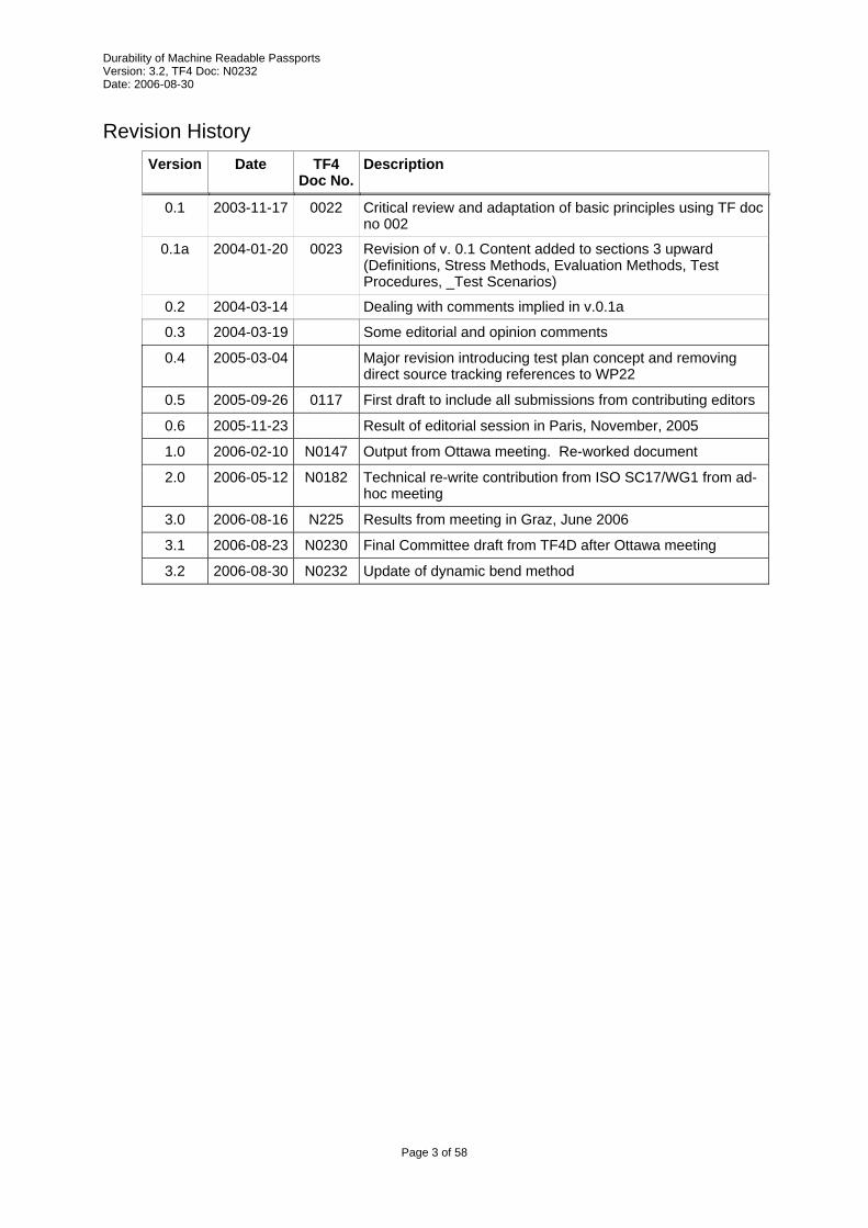
Revision History
Version Date TF4 Doc No.
Description
0.1 2003-11-17 0022 Critical review and adaptation of basic principles using TF doc no 002
0.1a 2004-01-20 0023 Revision of v. 0.1 Content added to sections 3 upward (Definitions, Stress Methods, Evaluation Methods, Test Procedures, _Test Scenarios)
0.2 2004-03-14 Dealing with comments implied in v.0.1a
0.3 2004-03-19 Some editorial and opinion comments
0.4 2005-03-04 Major revision introducing test plan concept and removing direct source tracking references to WP22
0.5 2005-09-26 0117 First draft to include all submissions from contributing editors
0.6 2005-11-23 Result of editorial session in Paris, November, 2005
1.0 2006-02-10 N0147 Output from Ottawa meeting. Re-worked document
2.0 2006-05-12 N0182 Technical re-write contribution from ISO SC17/WG1 from ad-hoc meeting
3.0 2006-08-16 N225 Results from meeting in Graz, June 2006
3.1 2006-08-23 N0230 Final Committee draft from TF4D after Ottawa meeting
3.2 2006-08-30 N0232 Update of dynamic bend method
Page 3 of 58
Durability of Machine Readable Passports Version: 3.2, TF4 Doc: N0232 Date: 2006-08-30
Table of Contents 1 Introduction ....................................................................................................................................... 6
1.1 Scope and Purpose .................................................................................................................... 6 1.2 Future Considerations ................................................................................................................ 6 1.3 Other Uses for this Document .................................................................................................... 6 1.4 Terminology................................................................................................................................ 7 1.5 Abbreviations .............................................................................................................................. 7 1.6 Terms and Definitions................................................................................................................. 7 1.7 References ................................................................................................................................. 9
2 Methodology.................................................................................................................................... 10 3 Guidance to the Tester.................................................................................................................... 12
3.1 Number of Samples.................................................................................................................. 12 3.2 Preparation ............................................................................................................................... 12 3.3 Sampling................................................................................................................................... 12 3.4 Storage ..................................................................................................................................... 12
4 Common Method Information.......................................................................................................... 13 4.1 Default Environment ................................................................................................................. 13 4.2 Climatic conditions.................................................................................................................... 13 4.3 Tolerances ................................................................................................................................ 13 4.4 Default MRP holder .................................................................................................................. 13
5 Stress Methods ............................................................................................................................... 14 5.1 Conditioning Stress Method ..................................................................................................... 14 5.2 Thermal Cycling Method........................................................................................................... 15 5.3 Storage Temperature Stress Method ....................................................................................... 16 5.4 Operational Temperature Stress Method ................................................................................. 17 5.5 Impact Stress Method............................................................................................................... 18 5.6 Book Bend Stress Method (Back Pocket) ................................................................................ 20 5.7 Dynamic Bend Stress Method .................................................................................................. 22 5.8 Torsion Stress Method ............................................................................................................. 25 5.9 Sheet Turning Stress Method................................................................................................... 27 5.10 Sheet Pull Stress Method ......................................................................................................... 28 5.11 Abrasion Stress Method ........................................................................................................... 29 5.12 Pen Stress Method ................................................................................................................... 30 5.13 Resistance to chemicals Evaluation Method............................................................................ 32 5.14 Artificial Daylight Exposure Stress Method .............................................................................. 34 5.15 X-Ray Stress Method ............................................................................................................... 35
6 Evaluation methods......................................................................................................................... 36 6.1 Functional PIC Evaluation Method ........................................................................................... 36 6.2 Physical Damage Evaluation Method....................................................................................... 37 6.3 Peel Strength Evaluation Method............................................................................................. 38 6.4 Colour Fastness Evaluation Method......................................................................................... 39 6.5 Datapage Warpage Evaluation Method ................................................................................... 40 6.6 Book Warpage Evaluation Method........................................................................................... 41
7 Test sequences............................................................................................................................... 42 7.1 General ..................................................................................................................................... 42 7.2 Instructions for using the Sequence Table ............................................................................... 42 7.3 Sheet Binding Sequence .......................................................................................................... 43 7.4 Storage Climate Sequence....................................................................................................... 44 7.5 Operational Climate Sequence................................................................................................. 45 7.6 Impact Sequence...................................................................................................................... 46 7.7 Back Pocket Sequence ............................................................................................................ 47 7.8 Torsion Fatigue Sequence ....................................................................................................... 48 7.9 Delamination Sequence ........................................................................................................... 49 7.10 Bending Fatigue Sequence ...................................................................................................... 50 7.11 Thermal Cycling Sequence ...................................................................................................... 51 7.12 Colour Fastness Sequence ...................................................................................................... 52 7.13 Resistance to Chemicals Sequence......................................................................................... 53 7.14 Pen Sequence .......................................................................................................................... 54 7.15 Datapage Abrasion Sequence.................................................................................................. 55 7.16 X-Ray Sequence....................................................................................................................... 56
8 Test plans........................................................................................................................................ 57
Page 4 of 58

Durability of Machine Readable Passports Version: 3.2, TF4 Doc: N0232 Date: 2006-08-30
8.1 General ..................................................................................................................................... 57 8.2 Minimum Level Test Plan ......................................................................................................... 58
Page 5 of 58
Durability of Machine Readable Passports Version: 3.2, TF4 Doc: N0232 Date: 2006-08-30
1 Introduction
1.1 Scope and Purpose
ICAO Doc. 9303, [R7], provides the basic functional specification for Machine Readable Travel Documents (MRTDs) and, together with the Supplement, [R10], which is published from time to time, describes all relevant properties of MRTD’s. Machine Readable Passports (MRP’s) are a subset of all MRTD’s. The publication of the Part 1 of the 6th edition of Doc 9303 introduces the contactless integrated circuit to the MRP. Such a passport containing a contactless integrated circuit is commonly referred to as an e-Passport.
This Test Specification provides a set of instructions for prototype evaluation of MRP’s which may incorporate contactless integrated circuits. Prototype evaluation is an instrument to establish the ability in principle of a specific type of document to fulfil the requirements of use. The procedure of prototype evaluation, therefore, is also referred to as “Type Evaluation”.
This document is a companion to ICAO Doc. 9303. It specifies the minimum criteria that shall be achieved in order to meet ICAO’s expectations for durability of fully personalized MRP’s. Therefore, by it’s existence, and endorsement by ICAO, this document implicitly defines additional requirements for Passports above and beyond Doc. 9303. Some of the tests described herein are also intended to serve as an instrument for the assessment of the ageing behaviour of the MRP and its components.
1.2 Future Considerations
Where technologies or combinations of technologies are to be applied in a MRP, which are not covered by the test methods described below, it is recommended to define such test methods based on available methods described in ISO/IEC, ANSI or any other accepted international standard organization in cooperation with the suppliers of such technologies.
Today, there is no stable state of the art regarding the correlation between stress and ageing, neither for previously existing nor for oncoming types of MRP. Related work by SC17/WG1/TF2 is still under way. The tests that can be described at the present stage may contribute to improve such knowledge but need to be considered preliminary. It is important to notice that ultimately, reliable and predictably useful correlations can only be achieved by continuously comparing the ageing behaviour of documents in real use to the predictions made. Such predictions are based on assumptions that, in particular if novel and unusual technologies and components are used, are in many cases unproven and preliminary in nature. It is one of the aims of this standard to help in the task of establishing sound correlations. This is done by providing tools for executing tests with comparable results for a multitude of acting parties. Comparable results are a prerequisite to encourage the execution of field surveys in quality related research and their use for a continuous improvement not only of this standard but also of the quality of MRP’s on a global basis.
1.3 Other Uses for this Document
The tests defined in this document may also be appropriate for other forms of MRTD, however, they may require modification before use.
Where applicable, tests may be used to evaluate characteristics of non-personalized MRP’s or materials used to make MRP’s.
Type Evaluation is usually a one-time exercise in the life cycle of a specific type of document. However the same test procedures may be useful for the proper definition of quality assurance procedures during the regular production of MRTD’s. In the framework of the contractual relationship between a manufacturer and his customer(s) it is common practice to establish an expected quality level for the MRTD’s in the delivery contract, and also to specify acceptance criteria for individual deliveries in executing the contract. On the other hand, it is good practice to leave it with the manufacturer to decide on the production quality measures to assure this quality level.
This specification has been carefully designed to provide the user with a set of tools for evaluating MRP’s, whether it be Prototype Evaluation, Delivery Acceptance, or any other purpose.
Because of the paramount importance of a common understanding between manufacturer and customer of the role of testing procedures in the production of security documents, an informative
Page 6 of 58

Durability of Machine Readable Passports Version: 3.2, TF4 Doc: N0232 Date: 2006-08-30
annex A may be included in a future version of the standard which gives a more detailed best practice survey of the principles of quality assurance and of the role that the present standard is expected to play in this context.
1.4 Terminology
For ICAO, keywords are SHALL, which means mandatory, and SHOULD, which is optional but is considered best practices.
1.5 Abbreviations
ICAO International Civil Aviation Organization
MRP Machine Readable Passport
MRTD Machine Readable Travel Document
PIC Proximity Integrated Circuit (note, Doc 9303 uses CIC (contactless integrated circuit) and PIC interchangeably)
1.6 Terms and Definitions
Constant Fixed values that can be given to parameters (within methods) when defining a sequence or test plan.
Evaluation Method method to measure numerical values for specific document properties
Evaluation Result All numerical values related to document properties measured upon performing a Test Sequence.
Method Instruction or set of instructions defining equipment and related tools and materials in an experimental setup, including general advice on their use in a specific test procedure.
Page indicates any single side of an individual sheet of the MRP.
Parameter A variable quantity within a test procedure that is not part of the instructions describing the procedure. In particular experimental parameters that need to be controlled during the test sequence but whose values and/or tolerances are not explicitly defined in a specific Stress or Evaluation Method or sequence.
Sheet any structure having a free edge and an opposite edge attached to the spine making up the MRP including covers, datapage, visa pages, observation pages, and chip sheet. Each sheet has 2 pages.
Stress Method An experimental setup and procedure that may or may not deteriorate or destroy the document under examination.
Test instruction A distinct piece of information required within the framework of test execution.
Test plan A list of Test Sequences and their specific Test Parameters and expected Evaluation Results.
Test procedure Set of instructions to be followed in order to obtain a test result.
Test sequence Test procedure that comprises a number of different methods in a defined order of execution.
Page 7 of 58

Durability of Machine Readable Passports Version: 3.2, TF4 Doc: N0232 Date: 2006-08-30
Type Evaluation or Type Approval Type approval is the process of testing a design (type of documents produced while using a common material and component basis and the same manufacturing processes, including same production quality assurance process) to ensure it is compliant-in-principle with the specifications.
Page 8 of 58

Durability of Machine Readable Passports Version: 3.2, TF4 Doc: N0232 Date: 2006-08-30
1.7 References The following normative documents contain provisions that, through reference in this text, constitute provisions of this technical report. For dated references, subsequent amendments to, or revisions of, any of these publications do not apply. However, parties to agreements based on this technical report are encouraged to investigate the possibility of applying the most recent editions of the normative documents indicated below. For undated references, the latest edition of the normative document referred to applies. [R1] ISO/IEC 10373-1:2006, Test methods — Part 1: General characteristics
[R2] ISO/IEC 10373-6:2001, Test methods – Proximity cards
[R3] ISO/IEC 10373-6:2001/FDAM1, Test methods – Proximity cards (Amendment 1: Protocol Test Methods for Proximity Cards)
[R4] ISO/IEC 10373-6:2001/AM2:2003, Test methods – Proximity cards (Amendment 2: Improved RF Test Methods)
[R5] ISO/IEC 10373-6:2001/FDAM4, Test methods – Proximity cards (Amendment 4: Additional Test Methods for PCD RF Interface and PICC Alternating Field Exposure)
[R6] ISO/IEC 10373-6:2001/FDAM5, Test methods – Proximity cards (Amendment 5: Bit Rates of fc/64, fc/32 and fc/16)
[R7] ICAO Doc 9303, Part 1, 6th edition, 2005, Machine Readable Travel Documents.
[R8] ISO 105-E04:1994, Textiles - Tests for colour fastness - Part E04: Colour fastness to perspiration.
[R9] ISO/IEC 7816-1, Identification cards – Integrated circuit cards – Part 1: Cards with contacts – Physical characteristics
[R10] ICAO Supplement to Doc 9303 as published from time to time.
[R11] ISO/IEC 7810, Identification cards - Physical characteristics.
[R12] TAG-MRTD/14-WP/22: Recommendations on Durability Measurement of Travel Documents, May 2003
[R13] ISO 12757: Ball point pens and refills
[R14] ISO 1817: Rubber, vulcanized - Determination of the effect of liquids
[R15] ISO 9227:1990: Corrosion tests in artficial atmoshpheres – salt spray tests
[R16] ISO 1302: Geometrical Product Specification (GPS) – Indication of surface texture in technical product documentation
[R17] RF Protocol and Application Test Standard for e-Passport – Part 2, WG3TF4_N0163, Version 0.9, 2006-02-10
[R18] ASTM E 832 – 81 (Reapproved 2003): Standard Specification for Laboratory Filter Papers
[R19] ISO 105-A02:1993: Textiles – Tests for colour fastness – Part A02: Grey scale for assessing change in colour
[R20] ISO 105-A02:1993 TECHNICAL CORRIGENDUM 2 (2005): Textiles – Tests for colour fastness – Part A02: Grey scale for assessing change in colour TECHNICAL CORRIGENDUM 2
[R21] ISO 105-B02:1994: Textiles – Tests for colour fastness – Part B02: Colour fastness to artificial light: Xenon arc fading lamp test
[R22] ISO 105-B02:1994 AMENDMENT 1 (1998): Textiles – Tests for colour fastness – Part B02: Colour fastness to artificial light: Xenon arc fading lamp test AMENDMENT 1
[R23] ISO 105-B02:1994 AMENDMENT 2 (2000): Textiles – Tests for colour fastness – Part B02: Colour fastness to artificial light: Xenon arc fading lamp test AMENDMENT 2
[R24] ISO 12040:1997: Graphic technology – Prints and printing inks – Assessment of light fastness using filtered xenon arc light
Page 9 of 58

Durability of Machine Readable Passports Version: 3.2, TF4 Doc: N0232 Date: 2006-08-30
2 Methodology The systemic approach used in this document provides three structural levels to define a complete test specification for MRP’s.
The first level deals with methods to exert defined stresses to documents and to evaluate the results of such stresses. The second level deals with predefined sequences of stresses and related evaluations using the methods defined in level 1. The third level specifies the lists of test sequences and the individual quantities of test specimens to be subject to each sequence. The purpose is to include in such lists all sequences that are considered necessary to achieve type approval for a specific type of MRP with specific lifetime and usage expectations. This is referred to as a test plan.
This approach provides flexibility in creating individual test plans appropriate for varying user requirements and MRP specifications without increasing the variety of basic testing methods beyond a strict minimum. It also allows the use of a parameterized method description; parameters, which may be explicitly specified on the sequence and/or test, plan level.
In this way this Test Specification provides the entire toolset for prototype evaluation of MRP’s.
Level Subject Description Degree of
variance Chapter
1 Stress methods The purpose is to submit the document(s) under evaluation to specific stress or environmental conditions in a well-defined experimental setup that ensures reproducibility.
Parameters 4
1 Evaluation methods The purpose is to measure numerical values for specific document properties using well-defined and reproducible experimental setups that may or may not deteriorate or destroy the document under examination.
Parameters 5
2 Test sequences Sequence of use of the above methods in performing a complete test.
Constants and
Parameters
6
3 Test plans Scenarios which link the user requirements to specific test sequences and related parameters used for the tests on the one hand and to specific test results on the other.
Constants 7
Table 1: Hierarchical Approach for Test Methodology
Page 10 of 58
Durability of Machine Readable Passports Version: 3.2, TF4 Doc: N0232 Date: 2006-08-30
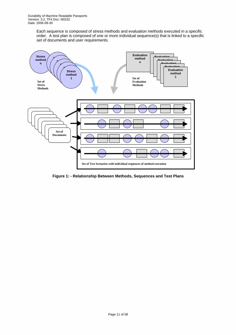
Each sequence is composed of stress methods and evaluation methods executed in a specific order. A test plan is composed of one or more individual sequence(s) that is linked to a specific set of documents and user requirements.
Stress method
n
Stress method
51 Stress
method 4 Stress
method3 Stress
method 2 Stress
method 1
Evaluationmethod
n
Evaluation method
5 Evaluation
method 4
Evaluation method
3 Evaluation
method 2
Evaluation method
1
Set of Documents
Set of Stress Methods
Set of EvaluationMethods
Set of Test Scenarios with individual sequences of method execution
Figure 1: - Relationship Between Methods, Sequences and Test Plans
Page 11 of 58
Durability of Machine Readable Passports Version: 3.2, TF4 Doc: N0232 Date: 2006-08-30
3 Guidance to the Tester
3.1 Number of Samples
References are given to a single MRP. However, multiple MRP samples may be tested simultaneously depending on the size and construction of the test apparatus.
3.2 Preparation
Test samples shall, wherever applicable, be either finished MRP's or be prepared from finished MRP's having passed the entire production process including visual personalisation with a dataset considered typical for the specific type of passport. Initialisation and personalisation of the chip may be done in an arbitrary way as long as the chip is able to support the necessary tests within the intended test sequence.
MRP’s shall be conditioned in accordance with 4.1.
Test pieces shall, as necessary, be prepared from the test samples in the particular form required by the test apparatus used.
3.3 Sampling
In certain cases samples may be taken from the base material before MRP manufacture if it can be demonstrated that no significant change in the property to be tested can arise during subsequent processing. The samples used to prepare a set of test pieces shall be taken from the same batch of MRP base materials.
3.4 Storage
Any test samples or test pieces retained for reference shall be stored under the environmental conditions specified in 4.1 Default Environment.
All such samples shall be clearly cross-referenced to the test report and any relevant supplementary documentation.
Page 12 of 58
Durability of Machine Readable Passports Version: 3.2, TF4 Doc: N0232 Date: 2006-08-30
4 Common Method Information
4.1 Default Environment
Unless otherwise specified, testing shall take place in an environment having a default temperature of 23 °C ± 3 °C (73 F ± 5 F) and relative humidity of 40% RH to 60% RH (ISO/IEC 10373-1).
4.2 Climatic conditions
Climatic conditions defined in the test methods given below are the conditions within the chamber. The resulting temperature in the MRP is not specified or defined in the methods.
4.3 Tolerances
Unless otherwise specified, a tolerance of ± 5% shall be applied to the quantity values given to specify the characteristics of the test equipment (e.g. linear dimensions) and the test method procedures (e.g. test equipment adjustments).
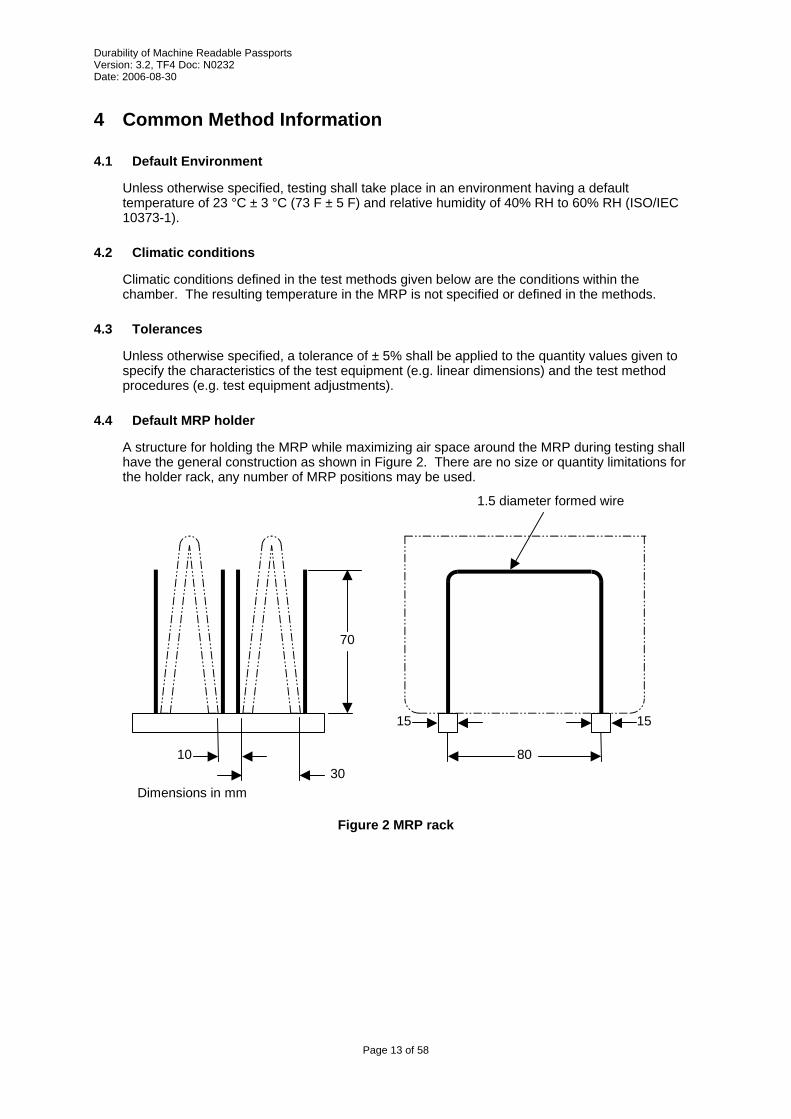
4.4 Default MRP holder
A structure for holding the MRP while maximizing air space around the MRP during testing shall have the general construction as shown in Figure 2. There are no size or quantity limitations for the holder rack, any number of MRP positions may be used.
10 30
70
80
15
1.5 diameter formed wire
15
Dimensions in mm
Figure 2 MRP rack
Page 13 of 58
Durability of Machine Readable Passports Version: 3.2, TF4 Doc: N0232 Date: 2006-08-30
5 Stress Methods Instructions and methods described below are designed to apply reproducible stresses to the travel document. Instructions and methods that describe how to measure the effect of these stresses are given in 6 Evaluation methods.
The fundamental philosophy behind all stress methods is to define conditions that mimic real daily use (as much as possible). In cases where the correlation between real life and the stress method is tenuous, every attempt has been made to define conditions that produce similar rates of deterioration.
5.1 Conditioning Stress Method
5.1.1 Introduction
The MRP’s to be tested shall be conditioned to the test environment as described below.
5.1.2 Input Parameters
t = time of conditioning. If t is not specified, assume 24 hours.
5.1.3 Apparatus
• Default MRP holder.
5.1.4 Method
• Remove MRP from any box and protective packaging.
• Place MRP in default MRP holder with spine up. MRP shall not be forced open but may open on its own. Minimum spacing between MRP and any other MRP shall be 10 mm in all directions.
• Expose MRP to a temperature of 23 °C ± 3 °C and relative humidity of 40%RH to 60%RH for at least time t.
Page 14 of 58
Durability of Machine Readable Passports Version: 3.2, TF4 Doc: N0232 Date: 2006-08-30
5.2 Thermal Cycling Method
5.2.1 Introduction
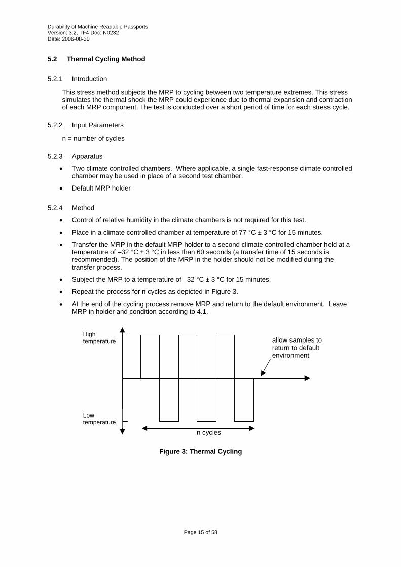
This stress method subjects the MRP to cycling between two temperature extremes. This stress simulates the thermal shock the MRP could experience due to thermal expansion and contraction of each MRP component. The test is conducted over a short period of time for each stress cycle.
5.2.2 Input Parameters
n = number of cycles
5.2.3 Apparatus
• Two climate controlled chambers. Where applicable, a single fast-response climate controlled chamber may be used in place of a second test chamber.
• Default MRP holder
5.2.4 Method
• Control of relative humidity in the climate chambers is not required for this test.
• Place in a climate controlled chamber at temperature of 77 °C ± 3 °C for 15 minutes.
• Transfer the MRP in the default MRP holder to a second climate controlled chamber held at a temperature of –32 °C ± 3 °C in less than 60 seconds (a transfer time of 15 seconds is recommended). The position of the MRP in the holder should not be modified during the transfer process.
• Subject the MRP to a temperature of –32 °C ± 3 °C for 15 minutes.
• Repeat the process for n cycles as depicted in Figure 3.
• At the end of the cycling process remove MRP and return to the default environment. Leave MRP in holder and condition according to 4.1.
High
temperature
n cycles
allow samples to return to default environment
Low temperature
Figure 3: Thermal Cycling
Page 15 of 58
Durability of Machine Readable Passports Version: 3.2, TF4 Doc: N0232 Date: 2006-08-30
5.3 Storage Temperature Stress Method
5.3.1 Introduction
This stress method applies high or low temperature and humidity to the document for specified amounts of time. This stress simulates a document’s exposure to various storage conditions. The purpose of the test is to demonstrate the resistance of MRP construction to such conditions in principle.
The test refers to temperature stability in Doc 9303: “2.4 Temperature stability. The MRP shall remain machine readable at operating temperatures ranging from –10/C to +50/C (14/F to 122/F). The MRP should not lose its reliability after being stored or exposed at temperatures ranging from –35/C to +80/C (–31/F to 176/F).”
Note that extremes of temperature may affect various security features, especially inks. Changes in these features shall not be considered a failure unless they render the document unrecognisable as belonging to the bearer.
5.3.2 Input Parameters
T = temperature at which the passport is stored
H = relative humidity for storage
5.3.3 Apparatus
• Climate controlled chamber.
• Default MRP holder
5.3.4 Method
• Place MRP in climate controlled chamber at temperature T ± 3°C and H Relative Humidity for 168 hours.
• Remove MRP
Page 16 of 58
Durability of Machine Readable Passports Version: 3.2, TF4 Doc: N0232 Date: 2006-08-30
5.4 Operational Temperature Stress Method
5.4.1 Introduction
This stress method applies high or low temperature and humidity to the document for specified amounts of time. This stress simulates a document’s exposure to various climatic conditions. The purpose of the test is to demonstrate the resistance of MRP construction to such conditions in principle.
The test refers to temperature stability in Doc 9303: “2.4 Temperature stability. The MRP shall remain machine readable at operating temperatures ranging from –10/C to +50/C (14/F to 122/F). The MRP should not lose its reliability after being stored or exposed at temperatures ranging from –35/C to +80/C (–31/F to 176/F).”
Note that extremes of temperature may affect various security features, especially inks. Changes in these features shall not be considered a failure unless they render the document unrecognisable as belonging to the bearer.
5.4.2 Input Parameters
T = temperature at which the passport is expected to operate
5.4.3 Apparatus
• Climate controlled chamber.
• Default MRP holder
5.4.4 Method
• Place MRP in climate controlled chamber at temperature T ± 3°C for 1 hour.
• Evaluate the MRP within the climate chamber.
Page 17 of 58
Durability of Machine Readable Passports Version: 3.2, TF4 Doc: N0232 Date: 2006-08-30
5.5 Impact Stress Method
5.5.1 Introduction
This stress method applies a certain forced impact to the sample to simulate stamping of the document at a border control point.
5.5.2 Input Parameters
S = sheet to be affected by impact. Note, as only visa pages will be impacted, sheet S may not be impacted directly.
5.5.3 Output Parameters
None
5.5.4 Apparatus
• Stamp:
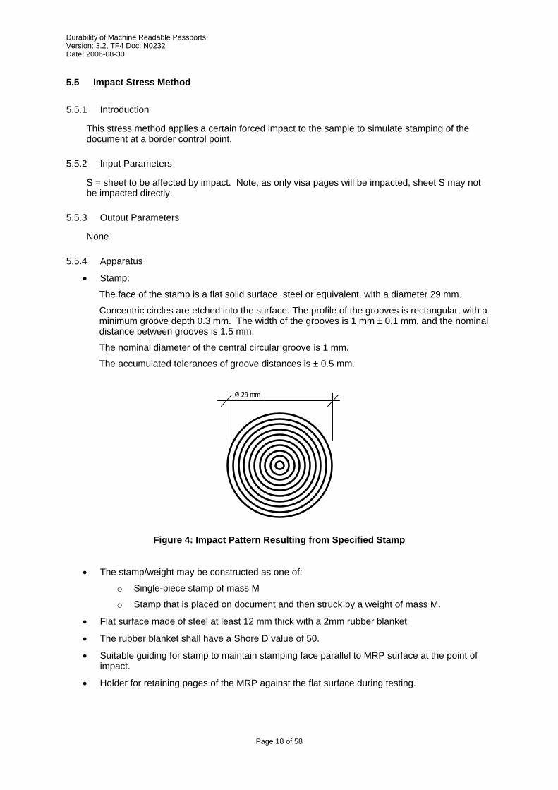
The face of the stamp is a flat solid surface, steel or equivalent, with a diameter 29 mm.
Concentric circles are etched into the surface. The profile of the grooves is rectangular, with a minimum groove depth 0.3 mm. The width of the grooves is 1 mm ± 0.1 mm, and the nominal distance between grooves is 1.5 mm.
The nominal diameter of the central circular groove is 1 mm.
The accumulated tolerances of groove distances is ± 0.5 mm.
Ø 29 mm
Figure 4: Impact Pattern Resulting from Specified Stamp
• The stamp/weight may be constructed as one of:
o Single-piece stamp of mass M
o Stamp that is placed on document and then struck by a weight of mass M.
• Flat surface made of steel at least 12 mm thick with a 2mm rubber blanket
• The rubber blanket shall have a Shore D value of 50.
• Suitable guiding for stamp to maintain stamping face parallel to MRP surface at the point of impact.
• Holder for retaining pages of the MRP against the flat surface during testing.
Page 18 of 58
Durability of Machine Readable Passports Version: 3.2, TF4 Doc: N0232 Date: 2006-08-30
• Description of stamp parameters:
H = nominal height (mm) from which an impact stamp is dropped onto the document or weight is dropped onto the stamp, thereby defining an impact velocity according to the formula for acceleration of inert bodies under earth gravitation.
H shall be between 0.05 m and 0.20 m
M = weight (kg) of the impact stamp
D = displacement between two impacts
The product P = H·M shall have a value of 0.02 kg·m.
If the apparatus is composed of a stamp that is impacted by a separate weight, the weight shall have mass M, and be dropped from a height H above the stamp. The mass of the stamp is not considered.
5.5.5 Method
• Locate the sheet S.
• Locate the nearest visa page that could require stamping and turn this over on top of the sheet under test. Depending on location, it is possible that there could be several sheets between the sheet S and the nearest visa page.
• Open MRP to 180 degrees and place on flat hard surface covered with a rubber coating so the outer cover is directly against the flat surface.
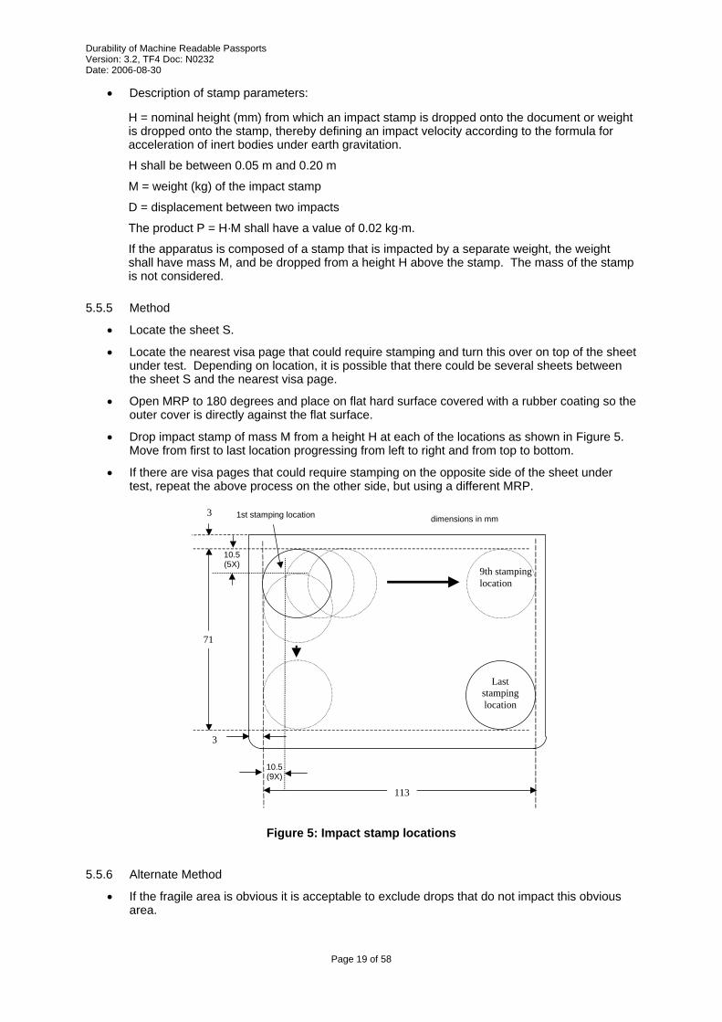
• Drop impact stamp of mass M from a height H at each of the locations as shown in Figure 5. Move from first to last location progressing from left to right and from top to bottom.
• If there are visa pages that could require stamping on the opposite side of the sheet under test, repeat the above process on the other side, but using a different MRP.
10.5 (9X)
10.5 (5X)
1st stamping location dimensions in mm
71
9th stamping location
Last stamping location
113
3
3
Figure 5: Impact stamp locations
5.5.6 Alternate Method
• If the fragile area is obvious it is acceptable to exclude drops that do not impact this obvious area.
Page 19 of 58
Durability of Machine Readable Passports Version: 3.2, TF4 Doc: N0232 Date: 2006-08-30
5.6 Book Bend Stress Method (Back Pocket)
5.6.1 Introduction
This test simulates on the stresses of sitting on a MRP, This method applies a force to the MRP and forces it to bend around a curved surface. The resulting stresses acting on the MRP are a combination of compression and bending stresses.
5.6.2 Input Parameters
n = number of cycles to apply force
5.6.3 Output Parameters
None
5.6.4 Apparatus
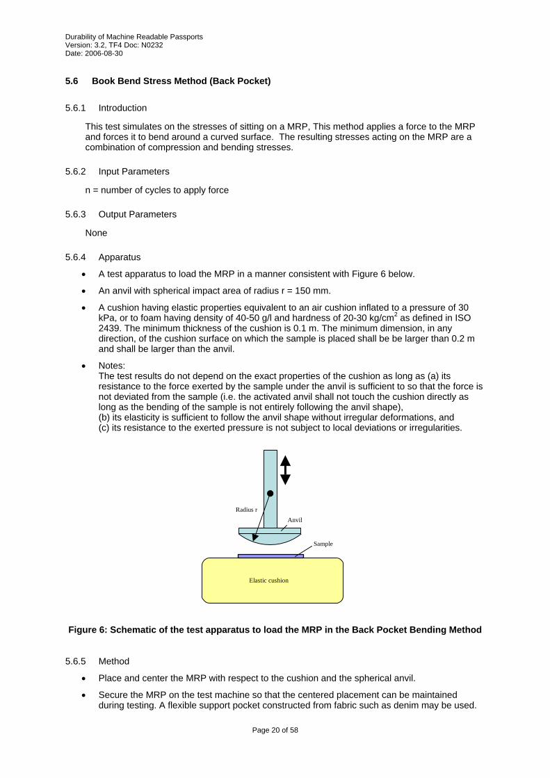
• A test apparatus to load the MRP in a manner consistent with Figure 6 below.
• An anvil with spherical impact area of radius r = 150 mm.
• A cushion having elastic properties equivalent to an air cushion inflated to a pressure of 30 kPa, or to foam having density of 40-50 g/l and hardness of 20-30 kg/cm2 as defined in ISO 2439. The minimum thickness of the cushion is 0.1 m. The minimum dimension, in any direction, of the cushion surface on which the sample is placed shall be be larger than 0.2 m and shall be larger than the anvil.
• Notes: The test results do not depend on the exact properties of the cushion as long as (a) its resistance to the force exerted by the sample under the anvil is sufficient to so that the force is not deviated from the sample (i.e. the activated anvil shall not touch the cushion directly as long as the bending of the sample is not entirely following the anvil shape), (b) its elasticity is sufficient to follow the anvil shape without irregular deformations, and (c) its resistance to the exerted pressure is not subject to local deviations or irregularities.
Radius r Anvil
Elastic cushion
Sample
Figure 6: Schematic of the test apparatus to load the MRP in the Back Pocket Bending Method
5.6.5 Method
• Place and center the MRP with respect to the cushion and the spherical anvil.
• Secure the MRP on the test machine so that the centered placement can be maintained during testing. A flexible support pocket constructed from fabric such as denim may be used.
Page 20 of 58

Durability of Machine Readable Passports Version: 3.2, TF4 Doc: N0232 Date: 2006-08-30
• Press the spherical anvil into the MRP and cushion support to a maximum force of 350 N. Maintain the applied force of 350 N for 5 s.
• Lift the spherical anvil so that it does not touch the MRP or cushion. The net external force acting on the MRP shall be less than 0.2 N.
• Repeat the loading and unloading process for a total of n times.
• Turn the MRP over and repeat the loading and unloading process n times.
Page 21 of 58
Durability of Machine Readable Passports Version: 3.2, TF4 Doc: N0232 Date: 2006-08-30
5.7 Dynamic Bend Stress Method
5.7.1 Introduction
The purpose of this test is to determine the bending fatigue resistance of the booklet construction to fully reversed loading. This method differs from the back pocket stress method by avoiding directly applied pressure. This method accelerates fatigue due to imposed bending, especially in the area of the antenna and associated connections if present.
5.7.2 Input Parameters
n = Number of bending cycles with the MRP
O = orientation of book in the bender
5.7.3 Output Parameters
None
5.7.4 Apparatus
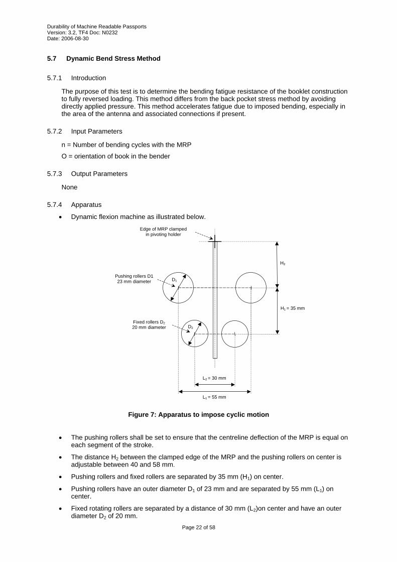
• Dynamic flexion machine as illustrated below.
Pushing rollers D1 23 mm diameter
Edge of MRP clamped in pivoting holder
Fixed rollers D2 20 mm diameter
D1
D2
H1 = 35 mm
H2
L2 = 30 mm
L1 = 55 mm
Figure 7: Apparatus to impose cyclic motion
• The pushing rollers shall be set to ensure that the centreline deflection of the MRP is equal on
each segment of the stroke.
• The distance H2 between the clamped edge of the MRP and the pushing rollers on center is adjustable between 40 and 58 mm.
• Pushing rollers and fixed rollers are separated by 35 mm (H1) on center.
• Pushing rollers have an outer diameter D1 of 23 mm and are separated by 55 mm (L1) on center.
• Fixed rotating rollers are separated by a distance of 30 mm (L2)on center and have an outer diameter D2 of 20 mm.
Page 22 of 58
Durability of Machine Readable Passports Version: 3.2, TF4 Doc: N0232 Date: 2006-08-30
5.7.5 Calibration of movement Method
• Taking into account, the specified orientation, O, the MRP shall be clamped at one extremity and allowed to freely move at the opposite edge.
• H2 should be adjusted depending on the orientation of the book
Orientation (O) H2
Spine clamped 40 mm
Top clamped 58 mm
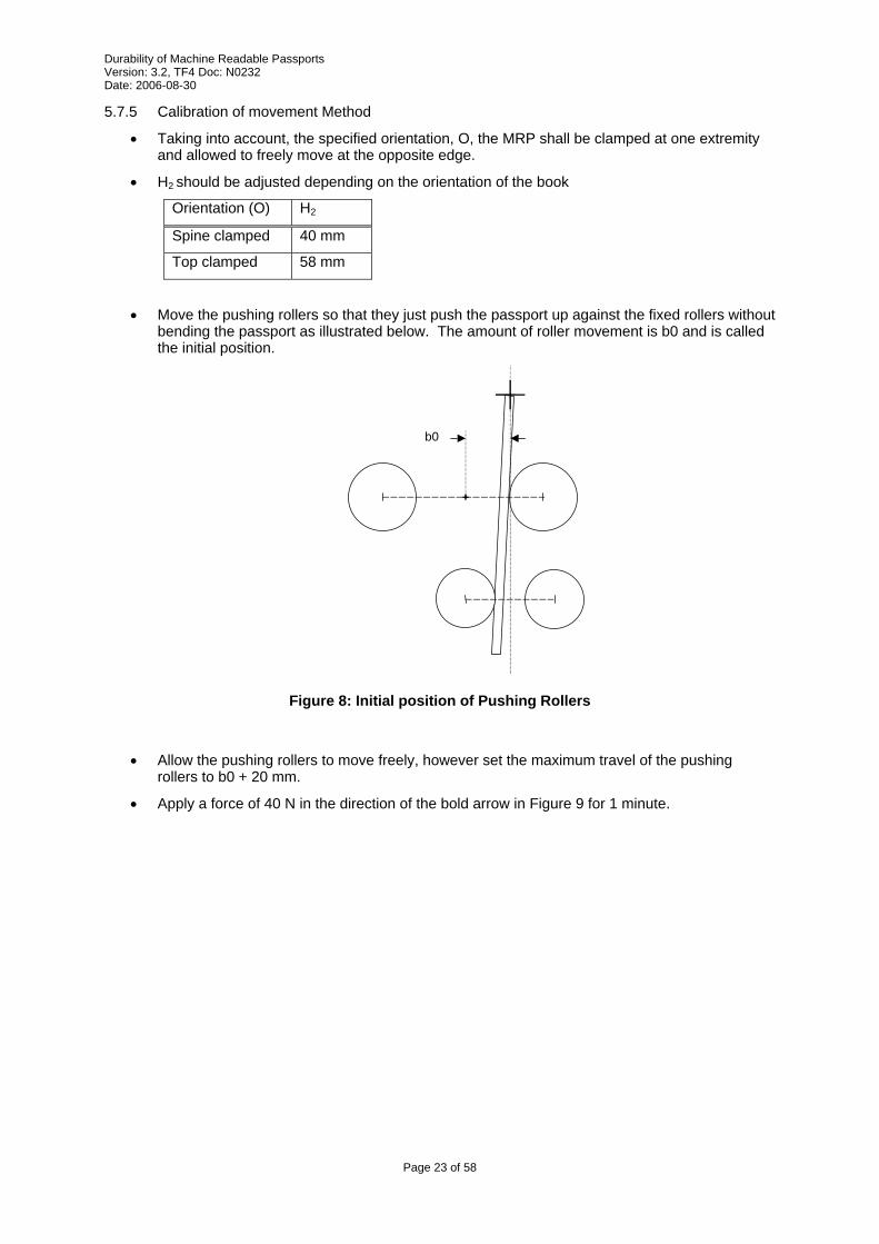
• Move the pushing rollers so that they just push the passport up against the fixed rollers without bending the passport as illustrated below. The amount of roller movement is b0 and is called the initial position.
b0
Figure 8: Initial position of Pushing Rollers
• Allow the pushing rollers to move freely, however set the maximum travel of the pushing rollers to b0 + 20 mm.
• Apply a force of 40 N in the direction of the bold arrow in Figure 9 for 1 minute.
Page 23 of 58
Durability of Machine Readable Passports Version: 3.2, TF4 Doc: N0232 Date: 2006-08-30
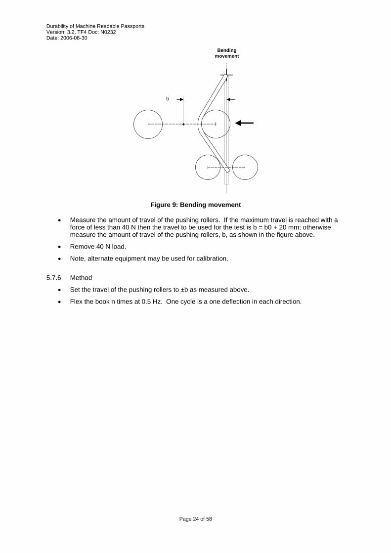
Bendingmovement
b
Figure 9: Bending movement
• Measure the amount of travel of the pushing rollers. If the maximum travel is reached with a force of less than 40 N then the travel to be used for the test is b = b0 + 20 mm; otherwise measure the amount of travel of the pushing rollers, b, as shown in the figure above.
• Remove 40 N load.
• Note, alternate equipment may be used for calibration.
5.7.6 Method
• Set the travel of the pushing rollers to ±b as measured above.
• Flex the book n times at 0.5 Hz. One cycle is a one deflection in each direction.
Page 24 of 58

Durability of Machine Readable Passports Version: 3.2, TF4 Doc: N0232 Date: 2006-08-30
5.8 Torsion Stress Method
5.8.1 Introduction
The purpose of this test is to determine adverse mechanical or functional effects in the MRP arising from torsional fatigue. This method differs from the back pocket stress method by applying only torsional stresses to the MRP.
5.8.2 Input parameters
n = Number of torsion cycles
5.8.3 Output parameters
None
5.8.4 Apparatus
• The test apparatus shall impose torsional motion in a manner consistent with Figure 10 shown below.
d = 127 mm
10 mm
Thickness of booklet + 0.5 mm
B A
Guide rails
+R +R
-R -R
C
Fixing point for booklet
R = Angle of rotationn
Figure 10: Schematic of the apparatus and the associated motion for torsion
5.8.5 Calibration
• Adjust separation of guide rails to thickness of book plus a maximum of 1 mm.
• Place MRP in test apparatus
• Set maximum travel of holders to 15 degrees.
• Apply a torque of 0.3 N-m for 1 minute.
• Measure amount of travel and reset maximum travel, R, of holder to amount measured.
Page 25 of 58

Durability of Machine Readable Passports Version: 3.2, TF4 Doc: N0232 Date: 2006-08-30
• Remove 0.3 N-m torque load.
• Note, alternate equipment may be used for calibration.
5.8.6 Method
• Place MRP in test apparatus
• One cycle consists of the following continuous steps (movement is not stopped at the 0 position except at that start and end of the test):
o Start from a point where both holder A and holder B are at angle 0
o Rotate holder A to angle +R, while simultaneously rotating holder B to angle –R.
o Rotate holder A to angle –R, while simultaneously rotating holder B to angle +R.
o Rotate holder A to angle 0, while simultaneously rotating holder B to angle 0.
• Operate the test apparatus at a speed of 0.5 Hz for n cycles.
Page 26 of 58
Durability of Machine Readable Passports Version: 3.2, TF4 Doc: N0232 Date: 2006-08-30
5.9 Sheet Turning Stress Method
5.9.1 Introduction
The purpose of the test is to determine the folding resistance of a sheet of a machine readable passport (MRP) at the spine.
5.9.2 Input Parameters
P = Sheet under test
n = Number of cycles
5.9.3 Output Parameters
None
5.9.4 Apparatus
• Fixture for clamping the fixed sheet or MRP
• Arm for rotation of sheet or MRP
• Device to apply force to sheet or MRP being tested.
• Note that no constraints are placed on machine design, including which clamp is fixed, which clamp moves, and which clamp force the force is applied to.
• Note also that the apparatus should prevent bending of the booklet in any other place than the axis of the booklet spine.
5.9.5 Method
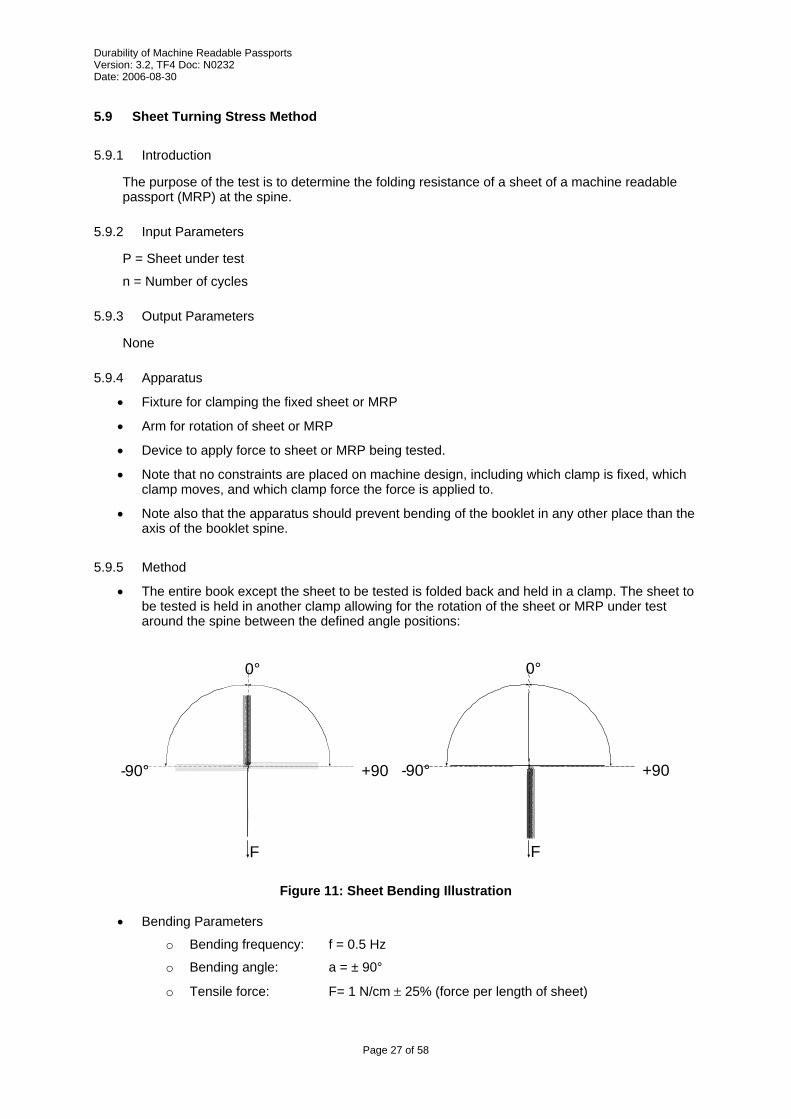
• The entire book except the sheet to be tested is folded back and held in a clamp. The sheet to be tested is held in another clamp allowing for the rotation of the sheet or MRP under test around the spine between the defined angle positions:
F
0°
+90- 90°
F
0°
+90-90°
Figure 11: Sheet Bending Illustration
• Bending Parameters
o Bending frequency: f = 0.5 Hz
o Bending angle: a = ± 90°
o Tensile force: F= 1 N/cm ± 25% (force per length of sheet)
Page 27 of 58
Durability of Machine Readable Passports Version: 3.2, TF4 Doc: N0232 Date: 2006-08-30
5.10 Sheet Pull Stress Method
5.10.1 Introduction
The purpose of the test is to determine the tearing resistance of the booklet pages and the sewing part during the usage of a machine readable passport (MRP).
5.10.2 Input Parameters
P = Sheet under test
5.10.3 Output Parameters
S = Maximum tearing strength in N/cm
5.10.4 Apparatus
• Clamp to hold MRP in a fixed position, minimum width of clamping area 130 mm
• Movable clamp for pulling on the page under test, minimum width of clamping area 130 mm
5.10.5 Method
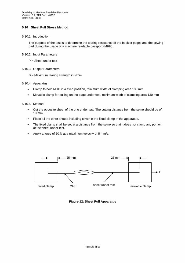
• Cut the opposite sheet of the one under test. The cutting distance from the spine should be of 10 mm.
• Place all the other sheets including cover in the fixed clamp of the apparatus.
• The fixed clamp shall be set at a distance from the spine so that it does not clamp any portion of the sheet under test.
• Apply a force of 60 N at a maximum velocity of 5 mm/s.
fixed clamp movable clamp
25 mm 25 mm
F
MRP sheet under test
Figure 12: Sheet Pull Apparatus
Page 28 of 58
Durability of Machine Readable Passports Version: 3.2, TF4 Doc: N0232 Date: 2006-08-30
5.11 Abrasion Stress Method
5.11.1 Introduction
The purpose of this test is to determine the effect of a specified mechanical abrasion to the Passport Data Page of an ICAO-compliant document. The main purpose is to test the machine-readable zone (MRZ) but the test might also be used for the Visual Inspection Zone (VIZ) or visa entries (sticker) of the passport. In order to perform this test, the datapage (visa page) shall be personalized.
The abrasive material to be used should be the material of the facing page.
5.11.2 Input Parameters
n = number of test cycles (double strokes)
5.11.3 Output Parameters
None
5.11.4 Apparatus
test load L = 14000 ± 5 % N/m2
length (or diameter) of test load D = 15 mm (width shall cover MRZ)
test speed v = between 2.5 and 25 cm/s
• The abrasive material has to be attached to the test load without protruding beyond the edge of the passport. If increased adhesion is required a double sided adhesive tape can be used.
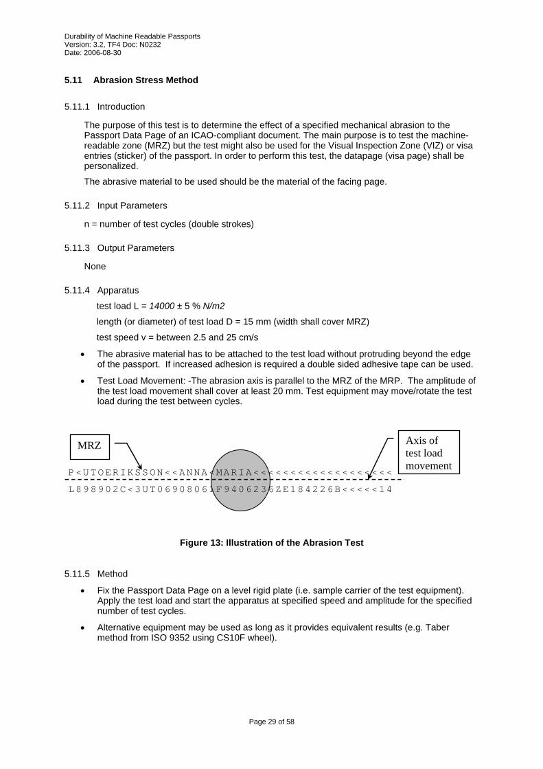
• Test Load Movement: -The abrasion axis is parallel to the MRZ of the MRP. The amplitude of the test load movement shall cover at least 20 mm. Test equipment may move/rotate the test load during the test between cycles.
P<UTOERIKSSON<<ANNA<MARIA<<<<<<<<<<<<<<<<<<<
L898902C<3UT06908061F9406236ZE184226B<<<<<14
MRZ Axis of test load movement
Figure 13: Illustration of the Abrasion Test
5.11.5 Method
• Fix the Passport Data Page on a level rigid plate (i.e. sample carrier of the test equipment). Apply the test load and start the apparatus at specified speed and amplitude for the specified number of test cycles.
• Alternative equipment may be used as long as it provides equivalent results (e.g. Taber method from ISO 9352 using CS10F wheel).
Page 29 of 58

Durability of Machine Readable Passports Version: 3.2, TF4 Doc: N0232 Date: 2006-08-30
5.12 Pen Stress Method
5.12.1 Introduction
The purpose of the test is to simulate writing over the PIC with a ball point pen simulating manual entries on visa pages. It is felt that depending on the construction of the passport, a pen might damage components of the passport (IC, inlay or paper).
The page to be written on shall be one that is normally written on and shall provide maximum stress to the chip (if present). In the case where it is possible to write on pages on both sides of the chip sheet, separate MRP’s should be evaluated.
Note, this method may not be suitable when devices like rivets are used. I.e. the pen may become damaged or stuck if features protrude from the page under test.
5.12.2 Input parameters
n = number of cycles
P = page to test
5.12.3 Output parameters
None
5.12.4 Apparatus
• Pen with ball point of diameter 0.7 mm compliant with ISO 12757-2.
• Pen positioning apparatus capable of pen movement in X and Y direction over the area shown in Figure 14. Pen shall be held at an angle of 90 degrees to the page under test.
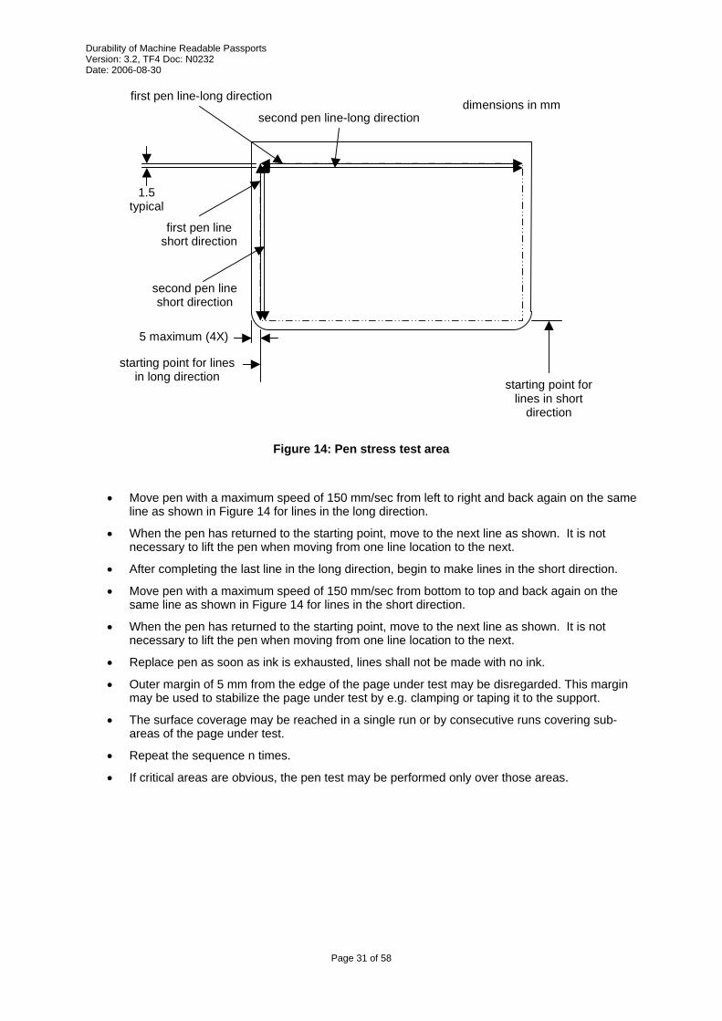
5.12.5 Method
• Choose a Page P to write on. It shall be a Page that is normally written on and shall provide maximum stress to the chip. In the case where it is possible to write on pages on both sides of the chip page, both sides will be tested.
• Clamp MRP in suitable holding fixture so pages do not move during testing.
• Apply a load to pen of 250 g downward toward pages under test.
• Apply a series of strokes, each in the form of a double line (movement back and forth along the same straight line and across the dimension of the sample) and at a nominal distance of 1.5 mm between lines.
Page 30 of 58
Durability of Machine Readable Passports Version: 3.2, TF4 Doc: N0232 Date: 2006-08-30
starting point for lines in long direction
1.5 typical
first pen line-long direction dimensions in mm
5 maximum (4X)
second pen line-long direction
first pen line short direction
second pen line short direction
starting point for lines in short
direction
Figure 14: Pen stress test area
• Move pen with a maximum speed of 150 mm/sec from left to right and back again on the same
line as shown in Figure 14 for lines in the long direction.
• When the pen has returned to the starting point, move to the next line as shown. It is not necessary to lift the pen when moving from one line location to the next.
• After completing the last line in the long direction, begin to make lines in the short direction.
• Move pen with a maximum speed of 150 mm/sec from bottom to top and back again on the same line as shown in Figure 14 for lines in the short direction.
• When the pen has returned to the starting point, move to the next line as shown. It is not necessary to lift the pen when moving from one line location to the next.
• Replace pen as soon as ink is exhausted, lines shall not be made with no ink.
• Outer margin of 5 mm from the edge of the page under test may be disregarded. This margin may be used to stabilize the page under test by e.g. clamping or taping it to the support.
• The surface coverage may be reached in a single run or by consecutive runs covering sub-areas of the page under test.
• Repeat the sequence n times.
• If critical areas are obvious, the pen test may be performed only over those areas.
Page 31 of 58

Durability of Machine Readable Passports Version: 3.2, TF4 Doc: N0232 Date: 2006-08-30
5.13 Resistance to chemicals Evaluation Method
5.13.1 Introduction
The purpose of this test is to determine any adverse effects of a range of chemical contaminants on an MRP test sample. It is possible that the document may not be useable for travel after this test, but it is expected that the book shall be identifiable as belonging to the bearer.
Certain security features incorporated into MRP’s are designed to react to reagents in order to show taat tampering has taken place. The action of these security features under the influence of the reagents shall not constitute a failure.
5.13.2 Input Parameters
None
5.13.3 Output Parameters
None
5.13.4 Apparatus
• MRP holder
• Solutions as required
5.13.5 Short Term Contamination Test
5.13.5.1 Short Term Reagents (list provided here for information only, defined in ISO/IEC 10373-1)
a) 5% by mass aqueous solution of sodium chloride (NaCl, 98% minimum assay);
b) 5% by mass aqueous solution of acetic acid (CH3COOH, 99% minimum assay);
c) 5% by mass aqueous solution of sodium carbonate (Na2CO3, 99% minimum assay);
d) 60% by mass aqueous solution of ethyl alcohol (CH3CH2OH, 93% minimum assay);
e) 10% by mass aqueous solution of sucrose (C12H22O11, 98% minimum assay);
f) Fuel B (according to ISO 1817);
g) 50% by mass aqueous solution of ethylene glycol (HOCH2CH2OH, 98% minimum assay).
5.13.5.2 Short Term Contamination Method • Use solutions as defined in ISO/IEC 10373-1.
• Use a different sample MRP for each solution.
• Prior to immersion in the test solution, fan the pages of the MRP such that the sheets of the MRP are exposed.
• Standing the MRP upright (spine is in a vertical orientation), submerge the MRP for 60 seconds in one of the solutions listed above. The solutions shall be kept at a temperature between 20 °C and 25 °C.
• Remove MRP from solution and place in default MRP holder for 24 hours at default temperature and humidity conditions. For those samples immersed in organic solvents (including fuel), this procedure should be performed within the confines of a fume hood.
5.13.6 Long Term Contamination Test
Page 32 of 58
5.13.6.1 Long Term Reagents (list provided here for information only, defined in ISO/IEC 10373-1)
a) salt mist;
Durability of Machine Readable Passports Version: 3.2, TF4 Doc: N0232 Date: 2006-08-30
b) artificial perspiration (both solutions shall be prepared in accordance with ISO 105-E04:1994): (i) alkaline solution; (ii) acid solution.
5.13.6.2 Method for Salt Mist • Use neutral solution as defined in ISO/IEC 10373-1.
• Use a different sample MRP for each test.
• For the salt mist exposure, mount the sample MRP vertically in a cabinet in accordance with ISO 9227:1990 for 24 hours.
• Remove MRP from solution and place in default MRP holder for 24 hours at default temperature and humidity conditions.
5.13.6.3 Method for Synthetic Perspiration • The filter paper shall be compliant with ASTM E 832. Any Type I filter paper for qualitative
analysis may be selected.
• Soak filter paper in the artificial perspiration solution. Allow excess liquid to drain for 10 seconds then place it on a flat non-absorbent surface (glass plate) to stabilise for 1minute.
• Wrap the sample MRP in the wetted filter paper and place this in a sealed plastic bag in an environment kept between 20 °C and 25 °C. The plastic bag shall be placed between flat plates with a 5 kg weight positioned on top.
• Leave the sample in this environment for 24 hours.
• Remove MRP from solution and place in default MRP holder for 24 hours at default temperature and humidity conditions.
Page 33 of 58
Durability of Machine Readable Passports Version: 3.2, TF4 Doc: N0232 Date: 2006-08-30
5.14 Artificial Daylight Exposure Stress Method
5.14.1 Introduction
This test is derived from ISO 105-B02 and exposes the sample to illumination from an artificial light source that represents natural daylight in the visible and near UV (UV A) spectral region. The aim of this test is to assess the resistance of the MRP to fading.
Note: The blue wool reference numbers refer to those preferred in Europe (1-8) and not those preferred in the US (L2-L9)
Note that this method is difficult to apply to ordinary security printing backgrounds due to the fine structure of the linework. It is acceptable to print samples using test patterns for each ink used in production to facilitate this test.
5.14.2 Input Parameters
P = page to expose
S = blue wool scale to measure exposure
5.14.3 Output Parameters
None
5.14.4 Apparatus
• An air-cooled xenon arc lamp apparatus with a well-ventilated exposure chamber and a xenon arc lamp of correlated colour temperature 5500 K – 6500 K shall be used. A light filter (glass filter) placed between light source and samples shall cut all radiation with wavelengths smaller than 310 nm. A heat filter placed between light source and samples shall be used in order to reduce IR radiation contained in the xenon arc spectrum.
5.14.5 Method
• Cut a sample from the MRP to required size for the test machine and place an opaque cover over a portion of the sample (for comparison purposes)
• Prepare the appropriate blue wool reference in the same way. Strips cut from the blue wool references 1 to S shall be used.
• Place samples together with the blue wool reference set in the accelerated daylight test apparatus and expose to artificial daylight according to Method 2 (ref. ISO 105 B-02) until the exposed part of the blue wool reference S has faded to the equivalent of gray scale 4
Page 34 of 58
Durability of Machine Readable Passports Version: 3.2, TF4 Doc: N0232 Date: 2006-08-30
5.15 X-Ray Stress Method
5.15.1 Introduction
The purpose of this test is to determine any adverse effects to the MRP by X-rays levels that might be encountered during border control screening. The MRP shall comply with the requirement in ISO/IEC 7816-1 when tested in accordance with ISO/IEC 10373-1.
5.15.2 Input parameter
None
5.15.3 Output Parameter
None
5.15.4 Apparatus
• Use apparatus defined by ISO/IEC 10373-3 for X-rays.
5.15.5 Method
• Follow the procedure in ISO/IEC 7816-1 for x-ray testing. (Substitute MRP for card, wherever it appears in the procedure in ISO/IEC 7816-1).
Page 35 of 58
Durability of Machine Readable Passports Version: 3.2, TF4 Doc: N0232 Date: 2006-08-30
6 Evaluation methods Evaluation methods are instructions describing how to measure specific attributes of the passport. Wherever applicable, the output of the evaluation method should be a numerical value that can be compared against a pass/fail criterion.
6.1 Functional PIC Evaluation Method
6.1.1 Introduction
This method evaluates the function of the Proximity Integrated Circuit (PIC). The method determines that chip is still sane and that it operates within normal and reasonable conditions. There is always a tradeoff between the execution time of this method and the completeness of the test.
If the MRP does not contain a chip, this evaluation method returns a Pass result.
6.1.2 Input Parameters
None
6.1.3 Output Parameters
R = Pass/Fail
6.1.4 Apparatus
• Commercial PIC reader.
6.1.5 Method
• Evaluate the PIC as per reference [9], RF Protocol and Application Test Standard for e-Passport – Part 2, WG3TF4_N0163, Version 0.9, 2006-02-10, section C.2.
Page 36 of 58
Durability of Machine Readable Passports Version: 3.2, TF4 Doc: N0232 Date: 2006-08-30
6.2 Physical Damage Evaluation Method
6.2.1 Introduction
The intent of this method is to verify that the passport is (still) suitable for use as a travel document. To pass the evaluation method, the document shall be intact, and shall still be machine readable. Some security features may be degraded or altered, however, the evaluation of these features may be subjective and specific to individual passports and are therefore outside the scope of this method.
6.2.2 Input Parameters
None
6.2.3 Output Parameters
R = Pass/Fail
6.2.4 Apparatus
None
6.2.5 Method
Physical damage and related acceptability levels are best evaluated by comparing the sample(s) under test to a set of evaluation samples that is considered to be just at the limit of acceptability. However as the authors need to put something prescriptive on paper, the following limits should be placed on a MRP for it to be useable. Future versions of this document will hopefully contain a more complete list of requirements. • The picture shall be reconizeable.
• Written information shall be legible, with no missing letters or words.
• The MRZ shall be machine readable.
• The MRP shall be Intact – no pages shall be separated.
• Opening the MRP to the datapage (180 degrees) shall not incur any further damage.
• opening the MRP to a visa page (180 degrees) shall not incur any further damage.
• The PIC containing part (Cover, Data Page, Special visa page) does not allow direct access to the chip or the antenna.
• No part of the datapage shall be missing.
• For datapages, more than 90% of the binding shall be intact.
• For other pages, more than 50% of the binding shall be intact.
• At least 50% of the hot-stamp on the cover shall be intact.
• Any holes in any sheets shall be less than 2mm in diameter.
• Areas of delamination along the edges shall be less than 3 mm deep, and 3 mm in length. Delaminations within the sheet shall be less than 3 mm in length.
Page 37 of 58
Durability of Machine Readable Passports Version: 3.2, TF4 Doc: N0232 Date: 2006-08-30
6.3 Peel Strength Evaluation Method
6.3.1 Introduction
The purpose of this test is to measure the peel strength between different layers used in passport constructions according to ISO/IEC 10373-1/5.3.
If the sheet to be evaluated is composed of multiple layers, the peel strength evaluation should be conducted on all layers. A separate document should be used for each layer so that a consistent number of strips will be cut from the sheet.
6.3.2 Input Parameters
P = sheet to perform test on
6.3.3 Output Parameters
F = strength (N/mm)
6.3.4 Apparatus
• Use apparatus defined in ISO/IEC 10373-1 Peel test method. References to “card” shall mean “sheet” for this test. If a stabilizing plate is required, a suitable size would be 95 mm x 130 mm.
6.3.5 Method
• Remove the sheet to be tested from the MRP
• Follow the method for peel strength measurements as outlined in ISO/IEC 10373-1, Peel test method, except for preconditioning and the direction and quantity of sample sections.
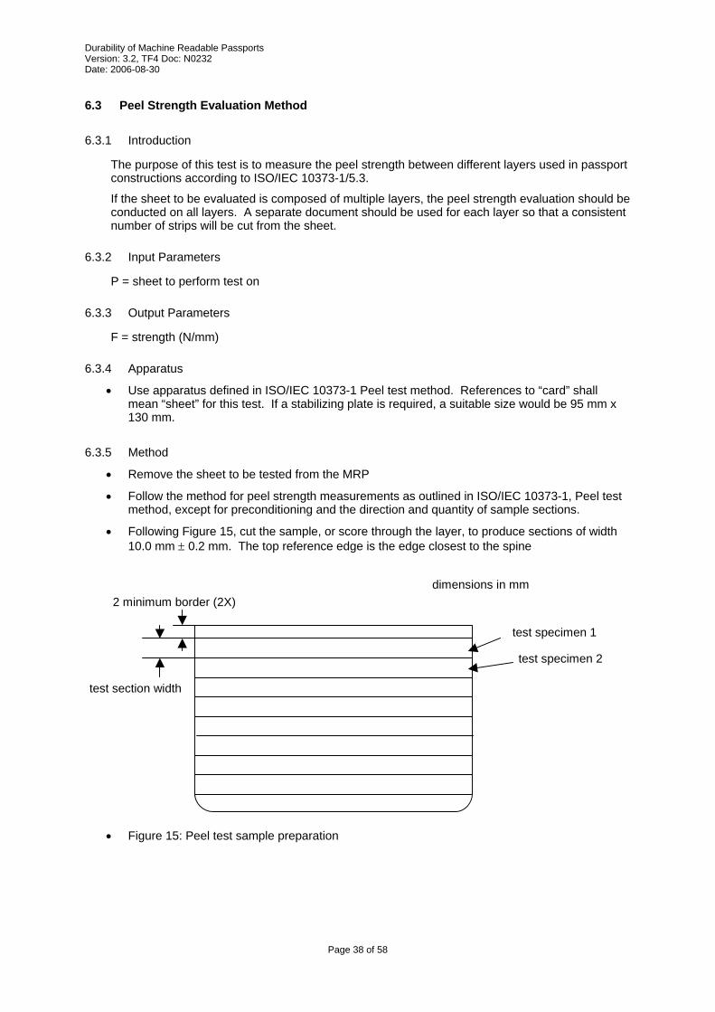
• Following Figure 15, cut the sample, or score through the layer, to produce sections of width 10.0 mm ± 0.2 mm. The top reference edge is the edge closest to the spine
test section width
test specimen 1
dimensions in mm 2 minimum border (2X)
test specimen 2
• Figure 15: Peel test sample preparation
Page 38 of 58

Durability of Machine Readable Passports Version: 3.2, TF4 Doc: N0232 Date: 2006-08-30
6.4 Colour Fastness Evaluation Method
6.4.1 Introduction
This evaluation method determines the change in appearance of the sample following exposure to artificial daylight. This evaluation method relies on the sample being subjected to 5.14 Artificial Daylight Exposure Stress Method.
6.4.2 Input Parameters
P = Page to evaluate
6.4.3 Output Parameters
R = Pass/Fail
6.4.4 Apparatus
None
6.4.5 Method
• Colour fastness evaluation derived from ISO 105-B02.
• The evaluation procedure is as follows:
• Visually evaluate fading or colour changes. For this purpose samples shall be illuminated by a D65 light source.
• Compare the contrast between exposed and unexposed sample with the contrast of gray scale 4.
• If the sample contrast is higher then the test result is Fail. If the sample contrast is less or equal then the test result is Pass.
Page 39 of 58
Durability of Machine Readable Passports Version: 3.2, TF4 Doc: N0232 Date: 2006-08-30
6.5 Datapage Warpage Evaluation Method
6.5.1 Introduction
The purpose of this test is to measure the extent of warpage in the MRP. The amount of warping in a MRP is important to ensure contactless IC and MRZ chip readability.
6.5.2 Input Parameters
None
6.5.3 Output Parameters
R = Pass/Fail
6.5.4 Apparatus:
• A level rigid surface whose roughness is not greater than 3.2 µm in accordance with ISO 1302.
• A flattening plate weighing 200 g measuring 88 mm x 125 mm.
• A height gauge or similar measuring device with a minimum accuracy of 0.1 mm.
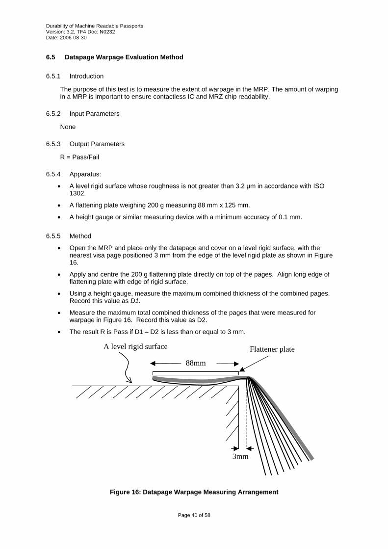
6.5.5 Method
• Open the MRP and place only the datapage and cover on a level rigid surface, with the nearest visa page positioned 3 mm from the edge of the level rigid plate as shown in Figure 16.
• Apply and centre the 200 g flattening plate directly on top of the pages. Align long edge of flattening plate with edge of rigid surface.
• Using a height gauge, measure the maximum combined thickness of the combined pages. Record this value as D1.
• Measure the maximum total combined thickness of the pages that were measured for warpage in Figure 16. Record this value as D2.
• The result R is Pass if D1 – D2 is less than or equal to 3 mm.
A level rigid surface Flattener plate
88mm
3mm
Figure 16: Datapage Warpage Measuring Arrangement
Page 40 of 58
Durability of Machine Readable Passports Version: 3.2, TF4 Doc: N0232 Date: 2006-08-30
6.6 Book Warpage Evaluation Method
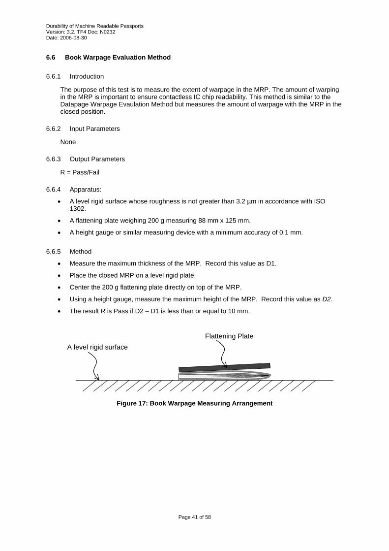
6.6.1 Introduction
The purpose of this test is to measure the extent of warpage in the MRP. The amount of warping in the MRP is important to ensure contactless IC chip readability. This method is similar to the Datapage Warpage Evaulation Method but measures the amount of warpage with the MRP in the closed position.
6.6.2 Input Parameters
None
6.6.3 Output Parameters
R = Pass/Fail
6.6.4 Apparatus:
• A level rigid surface whose roughness is not greater than 3.2 µm in accordance with ISO 1302.
• A flattening plate weighing 200 g measuring 88 mm x 125 mm.
• A height gauge or similar measuring device with a minimum accuracy of 0.1 mm.
6.6.5 Method
• Measure the maximum thickness of the MRP. Record this value as D1.
• Place the closed MRP on a level rigid plate.
• Center the 200 g flattening plate directly on top of the MRP.
• Using a height gauge, measure the maximum height of the MRP. Record this value as D2.
• The result R is Pass if D2 – D1 is less than or equal to 10 mm.
Flattening Plate
Page 41 of 58
A level rigid surface
Figure 17: Book Warpage Measuring Arrangement
Durability of Machine Readable Passports Version: 3.2, TF4 Doc: N0232 Date: 2006-08-30
7 Test sequences
7.1 General
Sequences are defined to specify the order in which stress methods and evaluation methods are to be performed in order to execute a specific test.
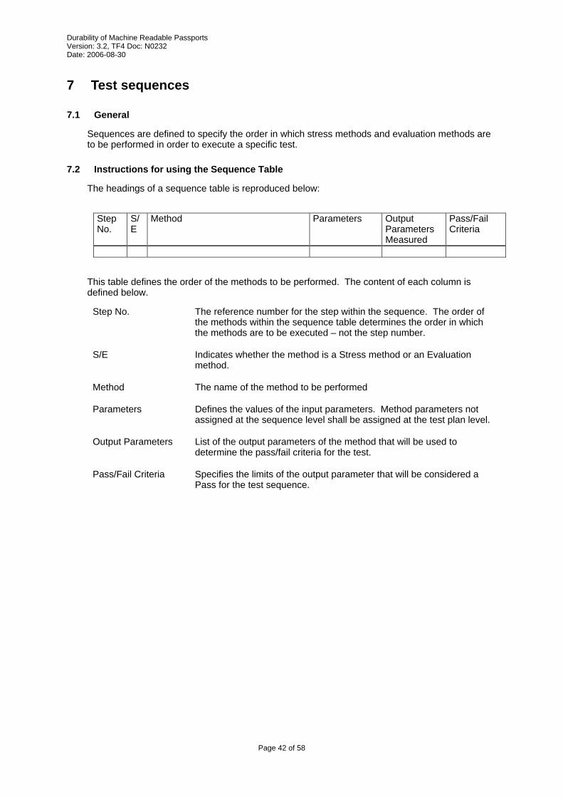
7.2 Instructions for using the Sequence Table
The headings of a sequence table is reproduced below:
Step No.
S/E
Method Parameters Output Parameters Measured
Pass/Fail Criteria
This table defines the order of the methods to be performed. The content of each column is defined below.
Step No. The reference number for the step within the sequence. The order of the methods within the sequence table determines the order in which the methods are to be executed – not the step number.
S/E Indicates whether the method is a Stress method or an Evaluation method.
Method The name of the method to be performed
Parameters Defines the values of the input parameters. Method parameters not assigned at the sequence level shall be assigned at the test plan level.
Output Parameters List of the output parameters of the method that will be used to determine the pass/fail criteria for the test.
Pass/Fail Criteria Specifies the limits of the output parameter that will be considered a Pass for the test sequence.
Page 42 of 58
Durability of Machine Readable Passports Version: 3.2, TF4 Doc: N0232 Date: 2006-08-30
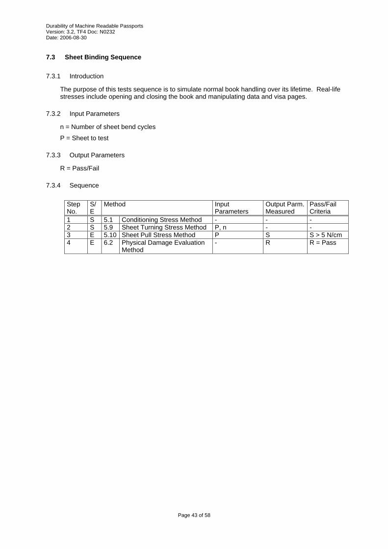
7.3 Sheet Binding Sequence
7.3.1 Introduction
The purpose of this tests sequence is to simulate normal book handling over its lifetime. Real-life stresses include opening and closing the book and manipulating data and visa pages.
7.3.2 Input Parameters
n = Number of sheet bend cycles
P = Sheet to test
7.3.3 Output Parameters
R = Pass/Fail
7.3.4 Sequence
Step No.
S/E
Method Input Parameters
Output Parm. Measured
Pass/Fail Criteria
1 S 5.1 Conditioning Stress Method - - - 2 S 5.9 Sheet Turning Stress Method P, n - - 3 E 5.10 Sheet Pull Stress Method P S S > 5 N/cm 4 E 6.2 Physical Damage Evaluation
Method- R R = Pass
Page 43 of 58
Durability of Machine Readable Passports Version: 3.2, TF4 Doc: N0232 Date: 2006-08-30
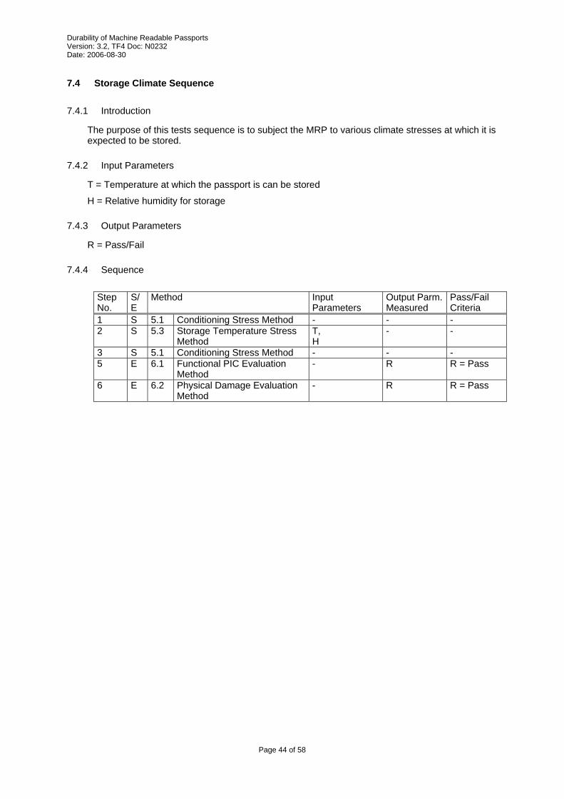
7.4 Storage Climate Sequence
7.4.1 Introduction
The purpose of this tests sequence is to subject the MRP to various climate stresses at which it is expected to be stored.
7.4.2 Input Parameters
T = Temperature at which the passport is can be stored
H = Relative humidity for storage
7.4.3 Output Parameters
R = Pass/Fail
7.4.4 Sequence
Step No.
S/E
Method Input Parameters
Output Parm. Measured
Pass/Fail Criteria
1 S 5.1 Conditioning Stress Method - - - 2 S 5.3 Storage Temperature Stress
MethodT, H
- -
3 S 5.1 Conditioning Stress Method - - - 5 E 6.1 Functional PIC Evaluation
Method- R R = Pass
6 E 6.2 Physical Damage Evaluation Method
- R R = Pass
Page 44 of 58

Durability of Machine Readable Passports Version: 3.2, TF4 Doc: N0232 Date: 2006-08-30
7.5 Operational Climate Sequence
7.5.1 Introduction
The purpose of this tests sequence is to subject the MRP to various climate stresses at which it is expected to operate.
7.5.2 Input Parameters
None
7.5.3 Output Parameters
R = Pass/Fail
7.5.4 Sequence
Step No.
S/E
Method Input Parameters
Output Parm. Measured
Pass/Fail Criteria
1 S 5.1 Conditioning Stress Method - - - 2 S 5.4 Operational Temperature
Stress MethodT = -7 - -
3 E 6.1 Functional PIC Evaluation Method
- R R = Pass
4 S 5.4 Operational Temperature Stress Method
T = 47 - -
5 E 6.1 Functional PIC Evaluation Method
- R R = Pass
6 S 5.1 Conditioning Stress Method - - - 7 E 6.2 Physical Damage Evaluation
Method- R R = Pass
Page 45 of 58
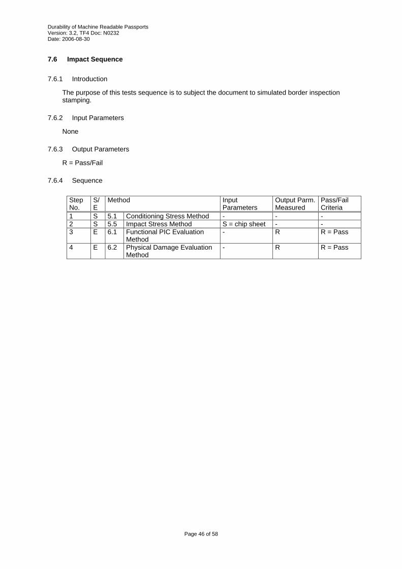
Durability of Machine Readable Passports Version: 3.2, TF4 Doc: N0232 Date: 2006-08-30
7.6 Impact Sequence
7.6.1 Introduction
The purpose of this tests sequence is to subject the document to simulated border inspection stamping.
7.6.2 Input Parameters
None
7.6.3 Output Parameters
R = Pass/Fail
7.6.4 Sequence
Step No.
S/E
Method Input Parameters
Output Parm. Measured
Pass/Fail Criteria
1 S 5.1 Conditioning Stress Method - - - 2 S 5.5 Impact Stress Method S = chip sheet - - 3 E 6.1 Functional PIC Evaluation
Method- R R = Pass
4 E 6.2 Physical Damage Evaluation Method
- R R = Pass
Page 46 of 58

Durability of Machine Readable Passports Version: 3.2, TF4 Doc: N0232 Date: 2006-08-30
7.7 Back Pocket Sequence
7.7.1 Introduction
The purpose of this tests sequence is to subject the document to simulated back-pocket stresses. Note that the number of cycles is quite low as sitting on a passport is considered accidental in “normal use”.
7.7.2 Input Parameters
None
7.7.3 Output Parameters
R = Pass/Fail
7.7.4 Sequence
Step No.
S/E
Method Input Parameters
Output Parm. Measured
Pass/Fail Criteria
1 S 5.1 Conditioning Stress Method - - - 2 S 5.6 Book Bend Stress Method
(Back Pocket)n = 10 - -
3 E 6.1 Functional PIC Evaluation Method
- R R = Pass
4 E 6.2 Physical Damage Evaluation Method
- R R = Pass
5 E 6.5 Datapage Warpage Evaluation Method
- R R = Pass
6 E 6.6 Book Warpage Evaluation Method
- R R = Pass
Page 47 of 58

Durability of Machine Readable Passports Version: 3.2, TF4 Doc: N0232 Date: 2006-08-30
7.8 Torsion Fatigue Sequence
7.8.1 Introduction
The purpose of this tests sequence is to subject the document to torsional forces.
7.8.2 Input Parameters
n = number of twisting cycles
7.8.3 Output Parameters
R = Pass/Fail
7.8.4 Sequence
Step No.
S/E
Method Input Parameters
Output Parm. Measured
Pass/Fail Criteria
1 S 5.1 Conditioning Stress Method - - - 2 S 5.8 Torsion Stress Method n - - 3 E 6.1 Functional PIC Evaluation
Method- R R = Pass
4 E 6.2 Physical Damage Evaluation Method
- R R = Pass
5 E 6.5 Datapage Warpage Evaluation Method
- R R = Pass
6 E 6.6 Book Warpage Evaluation Method
- R R = Pass
Page 48 of 58
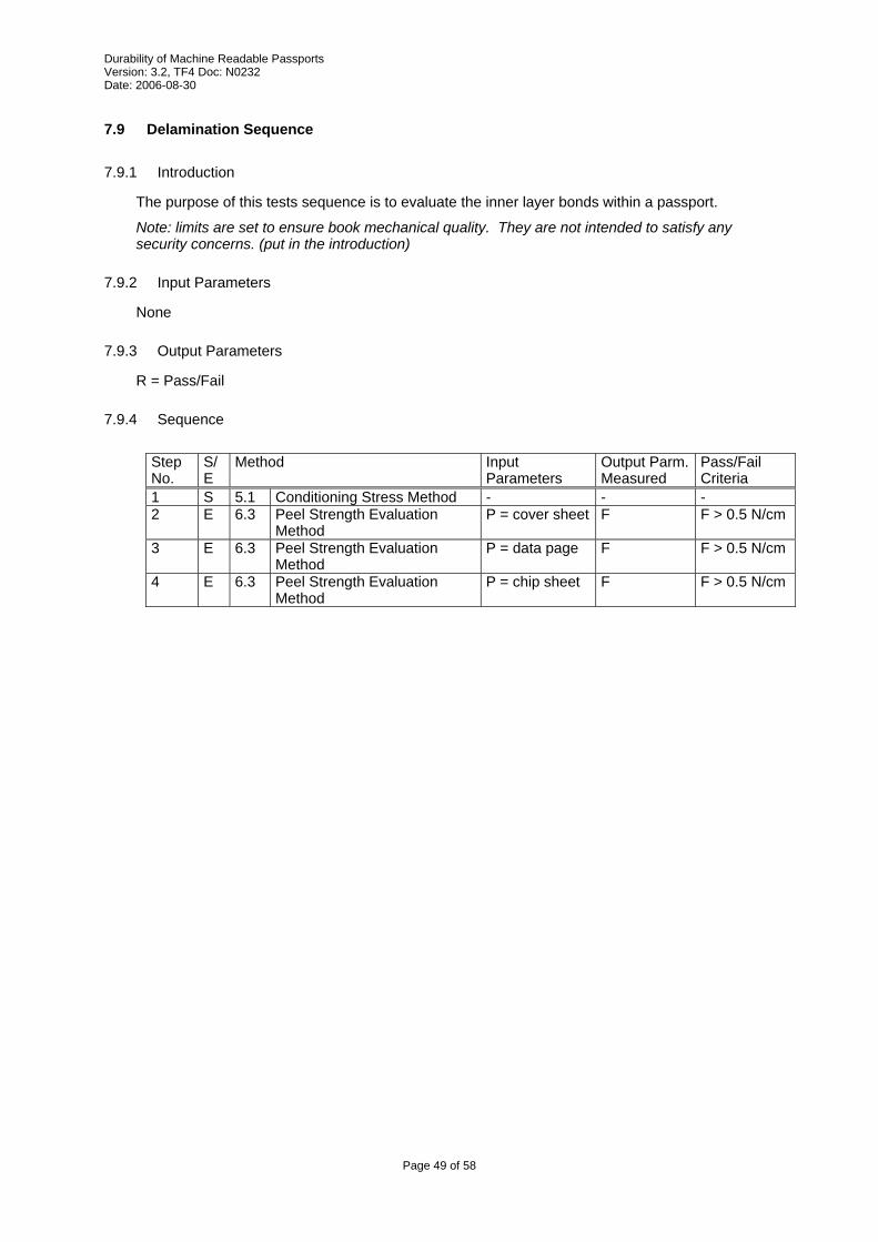
Durability of Machine Readable Passports Version: 3.2, TF4 Doc: N0232 Date: 2006-08-30
7.9 Delamination Sequence
7.9.1 Introduction
The purpose of this tests sequence is to evaluate the inner layer bonds within a passport.
Note: limits are set to ensure book mechanical quality. They are not intended to satisfy any security concerns. (put in the introduction)
7.9.2 Input Parameters
None
7.9.3 Output Parameters
R = Pass/Fail
7.9.4 Sequence
Step No.
S/E
Method Input Parameters
Output Parm. Measured
Pass/Fail Criteria
1 S 5.1 Conditioning Stress Method - - - 2 E 6.3 Peel Strength Evaluation
MethodP = cover sheet F F > 0.5 N/cm
3 E 6.3 Peel Strength Evaluation Method
P = data page F F > 0.5 N/cm
4 E 6.3 Peel Strength Evaluation Method
P = chip sheet F F > 0.5 N/cm
Page 49 of 58

Durability of Machine Readable Passports Version: 3.2, TF4 Doc: N0232 Date: 2006-08-30
7.10 Bending Fatigue Sequence
7.10.1 Introduction
The purpose of this tests sequence is to evaluate the susceptibility to fatigue of the passport.
7.10.2 Input Parameters
n = number of bending cycles
7.10.3 Output Parameters
R = Pass/Fail
7.10.4 Sequence
Step No.
S/E
Method Input Parameters
Output Parm. Measured
Pass/Fail Criteria
1 S 5.1 Conditioning Stress Method - - - 2 S 5.7 Dynamic Bend Stress Method O = spine
n - -
3 S 5.7 Dynamic Bend Stress Method O = top n
- -
4 E 6.1 Functional PIC Evaluation Method
- R R = Pass
5 E 6.2 Physical Damage Evaluation Method
- R R = Pass
6 E 6.5 Datapage Warpage Evaluation Method
- R R = Pass
7 E 6.6 Book Warpage Evaluation Method
- R R = Pass
Page 50 of 58
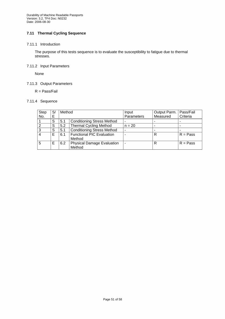
Durability of Machine Readable Passports Version: 3.2, TF4 Doc: N0232 Date: 2006-08-30
7.11 Thermal Cycling Sequence
7.11.1 Introduction
The purpose of this tests sequence is to evaluate the susceptibility to fatigue due to thermal stresses.
7.11.2 Input Parameters
None
7.11.3 Output Parameters
R = Pass/Fail
7.11.4 Sequence
Step No.
S/E
Method Input Parameters
Output Parm. Measured
Pass/Fail Criteria
1 S 5.1 Conditioning Stress Method - - - 2 S 5.2 Thermal Cycling Method n = 20 - - 3 S 5.1 Conditioning Stress Method - - - 4 E 6.1 Functional PIC Evaluation
Method- R R = Pass
5 E 6.2 Physical Damage Evaluation Method
- R R = Pass
Page 51 of 58

Durability of Machine Readable Passports Version: 3.2, TF4 Doc: N0232 Date: 2006-08-30
7.12 Colour Fastness Sequence
7.12.1 Introduction
The purpose of this tests sequence is to evaluate the susceptibility of the document to sunlight.
7.12.2 Input Parameters
None
7.12.3 Output Parameters
R = Pass/Fail
7.12.4 Sequence
Step No.
S/E
Method Input Parameters
Output Parm. Measured
Pass/Fail Criteria
1 S 5.1 Conditioning Stress Method - - - 2 S 5.14 Artificial Daylight Exposure
Stress MethodP = cover S = blue wool scale 6
- -
3 E 6.4 Colour Fastness Evaluation Method
- R R = Pass
4 S 5.14 Artificial Daylight Exposure Stress Method
P = datapage S = blue wool scale 3
- -
5 E 6.4 Colour Fastness Evaluation Method
- R R = Pass
6 S 5.14 Artificial Daylight Exposure Stress Method
P = chip sheet S = blue wool scale 3
- -
7 E 6.4 Colour Fastness Evaluation Method
- R R = Pass
Page 52 of 58

Durability of Machine Readable Passports Version: 3.2, TF4 Doc: N0232 Date: 2006-08-30
7.13 Resistance to Chemicals Sequence
7.13.1 Introduction
This sequence subjects passports to a range of chemicals that are commonly found in day-to-day situations.
Normally, a sequence would be applied in exactly the same manner to all samples. However for editorial convenience, this sequence covers all of the different solutions, and therefore will require at least 10 passport samples for evaluation.
7.13.2 Input Parameters
None
7.13.3 Output Parameters
R = Pass/Fail
7.13.4 Sequence
Step No.
S/E
Method Input Parameters
Output Parm. Measured
Pass/Fail Criteria
1 S 5.1 Conditioning Stress Method - - - 2 S 5.13 Resistance to chemicals
Evaluation Method- - -
3 E 6.1 Functional PIC Evaluation Method
- R R = Pass
4 E 6.2 Physical Damage Evaluation Method
- R R = Pass
Page 53 of 58

Durability of Machine Readable Passports Version: 3.2, TF4 Doc: N0232 Date: 2006-08-30
7.14 Pen Sequence
7.14.1 Introduction
The purpose of this tests sequence is to simulate writing on the passport. As currently defined, the pen test may be destructive to the visa page; therefore, only the chip is evaluated.
7.14.2 Input Parameters
None
7.14.3 Output Parameters
R = Pass/Fail
7.14.4 Sequence
Step No.
S/E
Method Input Parameters
Output Parm. Measured
Pass/Fail Criteria
1 S 5.1 Conditioning Stress Method - - - 2 S 5.12 Pen Stress Method n =1
P = writeable page nearest chip (both sides if possible)
- -
3 E 6.1 Functional PIC Evaluation Method
- R R = Pass
4 E 6.2 Physical Damage Evaluation Method
- R R = Pass
Page 54 of 58
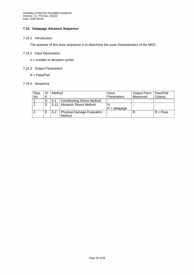
Durability of Machine Readable Passports Version: 3.2, TF4 Doc: N0232 Date: 2006-08-30
7.15 Datapage Abrasion Sequence
7.15.1 Introduction
The purpose of this tests sequence is to determine the wear characteristics of the MRZ.
7.15.2 Input Parameters
n = number of abrasion cycles
7.15.3 Output Parameters
R = Pass/Fail
7.15.4 Sequence
Step No.
S/E
Method Input Parameters
Output Parm. Measured
Pass/Fail Criteria
1 S 5.1 Conditioning Stress Method - - - 2 S 5.11 Abrasion Stress Method N
P = datapage - -
3 E 6.2 Physical Damage Evaluation Method
- R R = Pass
Page 55 of 58
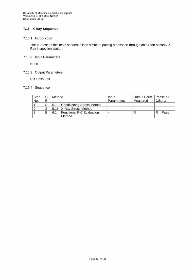
Durability of Machine Readable Passports Version: 3.2, TF4 Doc: N0232 Date: 2006-08-30
7.16 X-Ray Sequence
7.16.1 Introduction
The purpose of this tests sequence is to simulate putting a passport through an airport security X-Ray inspection station.
7.16.2 Input Parameters
None
7.16.3 Output Parameters
R = Pass/Fail
7.16.4 Sequence
Step No.
S/E
Method Input Parameters
Output Parm. Measured
Pass/Fail Criteria
1 S 5.1 Conditioning Stress Method - - - 2 S 5.15 X-Ray Stress Method - - - 3 E 6.1 Functional PIC Evaluation
Method- R R = Pass
Page 56 of 58
Durability of Machine Readable Passports Version: 3.2, TF4 Doc: N0232 Date: 2006-08-30
8 Test plans
8.1 General
The test plan is the top level of the test specification. It specifies values for any undefined sequence parameters, and defines the number of books that need to be subjected to each sequence.
Different test plans are defined depending on what is being tested and why. The default test plan is the “minimum durability required by ICAO”. Other test plans can be defined that might set other requirements. For example a 10-year normal use book, or a 5-year heavy use book
Each Lot is composed of new books. Books from one lot shall not be used in the test sequence of another lot.
The lot sizes specify the minimum number of books to be subjected to the test sequence. In general, small lot sizes do not give good statistical results, however very large lot sizes can become expensive to produce and to test. Only absolute minimums are given here. The customer and the tester are free to agree on other lot sizes that are larger than the minimum.
The reader is again reminded that this document is designed to provide a method of prototype testing (Type Approvals). It is not intended to be used to determine if individual documents meet specific standards.
The tester is reminded that while book manufacturers strive for perfect quality, it is possible that faulty samples may be subjected to testing. In the case of a failure, the tester should evaluate the failure, and in consultation with the manufacturer, should decide whether to select another sample for testing.
Page 57 of 58
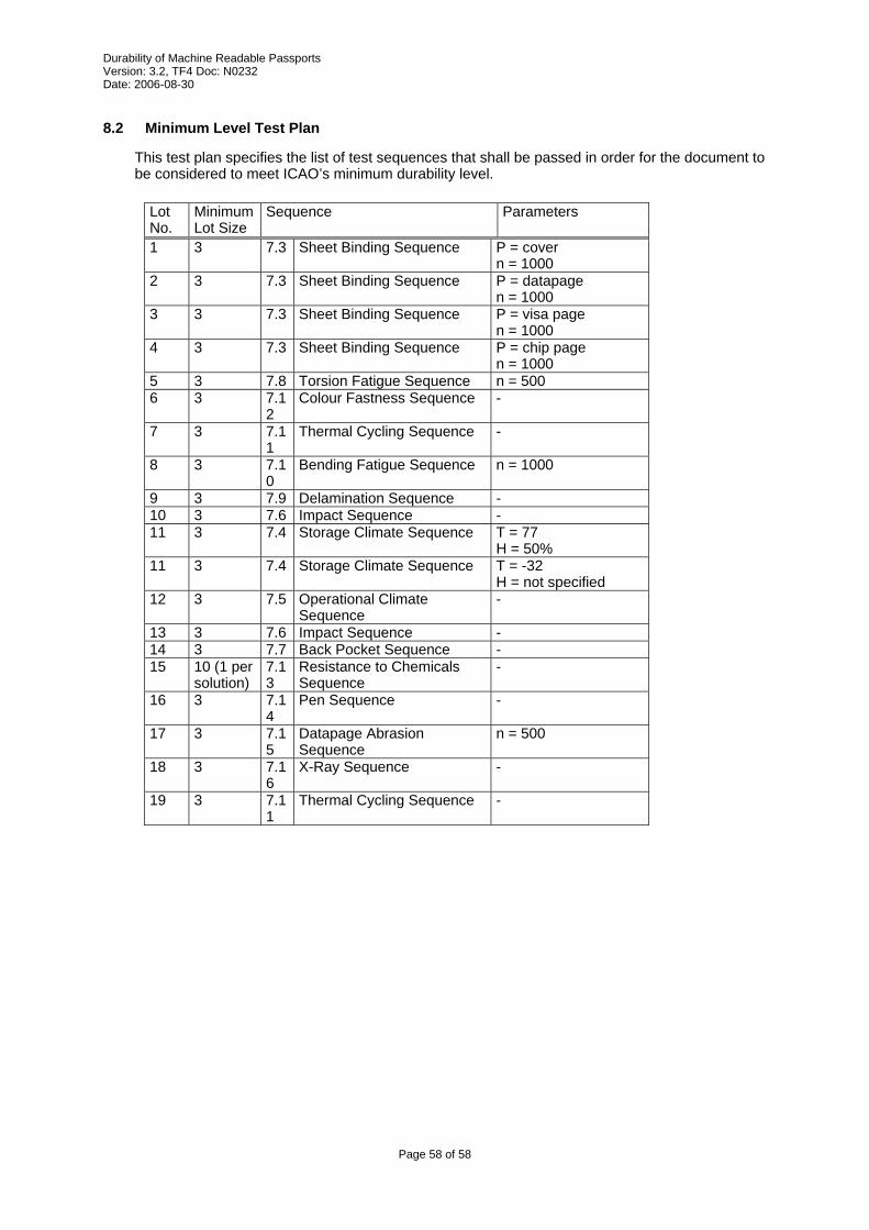
Durability of Machine Readable Passports Version: 3.2, TF4 Doc: N0232 Date: 2006-08-30
8.2 Minimum Level Test Plan
This test plan specifies the list of test sequences that shall be passed in order for the document to be considered to meet ICAO’s minimum durability level.
Lot No.
Minimum Lot Size
Sequence Parameters
1 3 7.3 Sheet Binding Sequence P = cover n = 1000
2 3 7.3 Sheet Binding Sequence P = datapage n = 1000
3 3 7.3 Sheet Binding Sequence P = visa page n = 1000
4 3 7.3 Sheet Binding Sequence P = chip page n = 1000
5 3 7.8 Torsion Fatigue Sequence n = 500 6 3 7.1
2Colour Fastness Sequence -
7 3 7.11
Thermal Cycling Sequence -
8 3 7.10
Bending Fatigue Sequence n = 1000
9 3 7.9 Delamination Sequence - 10 3 7.6 Impact Sequence - 11 3 7.4 Storage Climate Sequence T = 77
H = 50% 11 3 7.4 Storage Climate Sequence T = -32
H = not specified 12 3 7.5 Operational Climate
Sequence-
13 3 7.6 Impact Sequence - 14 3 7.7 Back Pocket Sequence - 15 10 (1 per
solution) 7.13
Resistance to Chemicals Sequence
-
16 3 7.14
Pen Sequence -
17 3 7.15
Datapage Abrasion Sequence
n = 500
18 3 7.16
X-Ray Sequence -
19 3 7.11
Thermal Cycling Sequence -
Page 58 of 58
File : RF protocol Part 2 V1.02.doc
Author : ISO/JTC1/SC17/WG3/TF4 for ICAO-NTWG
MACHINE READABLE
TRAVEL DOCUMENTS
TECHNICAL REPORT
RF PROTOCOL AND APPLICATION TEST STANDARD
FOR E-PASSPORT - PART 2
TESTS FOR AIR INTERFACE, INITIALISATION,
ANTICOLLISION AND TRANSPORT PROTOCOL
Version: 1.02
Date – Feb 20, 2007
Published by authority of the Secretary General
INTERNATIONAL CIVIL AVIATION ORGANIZATION
APPENDIX B
RF protocol and application test standard for e-Passport - part 2 Version : 1.02
Date : Feb 20, 2007
2 of 42
Release Control
Release Date Description
0.1 2005-11-23 First draft based on the German WG3 TF4 contribution “e-Passport Conformity
Testing” version 1.02 presented at TF4 meeting in Paris Nov 21-23, 2005
0.2 2005-12-09 Updated version with comments made during Paris meeting and new ICAO TR
layout.
0.9 2006-02-10 Updated version including accepted comments from the Ottawa meeting Jan 29 –
Feb 01, 2006 and editorial changes.
0.91 2006-06-28 Intermediate draft, updated version with resolved comments from the Graz meeting
Jun 12-13, 2006 and editorial changes. Some comments from Graz still unresolved.
0.95 2006-08-31 Updated version, editorial changes
0.96 2006-11-21 Internal draft version including all resolved comments from the Bled meeting, Oct
25-26, 2006 with a proposal to resolve comments on chapter 5.6. New test case 5.7
introduced.
1.0 2006-11-30 Final version including editorial changes in test case 5.7.
1.01 2006-12-07 Version update due to editorial corrections in the following test cases:
Chapter 5.7: Timing after SCIC EOF (TR2) (type B only). The minimum TR2 is
changed according to [R16].
Chapter 6.1.4: Handling of PPS. Wrong references are replaced.
Chapter 6.3.5: Data exchange protocol tests. Test scenarios G53 / G54 SHOULD be
omitted.
1.02 2007-02-20 Annex A removed.
Release Note:
Release 2007-02-20 is the official version of the technical report by SC17 WG3
TF4 endorsed by ICAO-NTWG at the Portugal meeting. It replaces version
1.01.
RF protocol and application test standard for e-Passport - part 2 Version : 1.02
Date : Feb 20, 2007
3 of 42
Table of contents
1 INTRODUCTION......................................................................................................................................... 5
1.1 SCOPE AND PURPOSE............................................................................................................................... 5 1.2 ASSUMPTIONS ......................................................................................................................................... 5
1.2.1 Maintenance of this TR regarding ISO standards ............................................................................. 5 1.3 TERMINOLOGY ........................................................................................................................................ 5 1.4 GLOSSARY .............................................................................................................................................. 6 1.5 ABBREVIATIONS...................................................................................................................................... 6 1.6 REFERENCE DOCUMENTATION ................................................................................................................ 7
2 GENERAL TEST REQUIREMENTS ........................................................................................................ 8
2.1 TEST SETUP ............................................................................................................................................. 8 2.2 EQUIPMENT............................................................................................................................................. 8 2.3 NOMINAL VALUES ................................................................................................................................... 9 2.4 REPORT................................................................................................................................................... 9 2.5 IMPLEMENTATION CONFORMANCE STATEMENT .................................................................................... 10 2.6 TEST SEQUENCE .................................................................................................................................... 10
3 LAYER 1 TESTS ........................................................................................................................................ 11
3.1 CLASS-1 VERIFICATION TEST (CONDITIONAL) ........................................................................................ 11 3.2 STATIC ELECTRICITY (ESD) TEST .......................................................................................................... 11 3.3 ALTERNATING MAGNETIC FIELD TEST.................................................................................................... 12
4 LAYER 2 TESTS ........................................................................................................................................ 12
4.1 LOAD MODULATION AMPLITUDE TEST ................................................................................................... 12 4.2 OPERATING FIELD STRENGTH TEST ........................................................................................................ 14
4.2.1 Type A .............................................................................................................................................. 14 4.2.2 Type B .............................................................................................................................................. 16
4.3 COMMUNICATION STABILITY TEST ........................................................................................................ 18 4.3.1 Type A .............................................................................................................................................. 18 4.3.2 Type B .............................................................................................................................................. 21
4.4 RESONANCE FREQUENCY TEST (OPTIONAL)........................................................................................... 23
5 LAYER 3 TIMING AND FRAMING TESTS.......................................................................................... 24
5.1 STARTUP TIME - POLLING ...................................................................................................................... 24 5.1.1 Type A .............................................................................................................................................. 24 5.1.2 Type B .............................................................................................................................................. 24
5.2 FRAME DELAY TIME (TYPE A ONLY)...................................................................................................... 25 5.3 START-OF-FRAME AND END-OF-FRAME TIMING (TYPE B ONLY) .......................................................... 25 5.4 EXTRA GUARD TIME (TYPE B ONLY)...................................................................................................... 26 5.5 TIMING BEFORE SCIC SOF (TR0 AND TR1) (TYPE B ONLY)................................................................. 26 5.6 TIMING AFTER SCIC EOF (SUBCARRIER TURN-OFF TIME) (TYPE B ONLY) ............................................ 28 5.7 TIMING AFTER SCIC EOF (TR2) (TYPE B ONLY) .................................................................................. 28
6 LAYER 3 AND 4 PROTOCOL TESTS.................................................................................................... 29
6.1 TYPE A ACTIVATION ............................................................................................................................. 29 6.1.1 State transitions ............................................................................................................................... 29 6.1.2 Handling of type A anticollision ...................................................................................................... 30 6.1.3 Handling of RATS............................................................................................................................ 30 6.1.4 Handling of PPS .............................................................................................................................. 30 6.1.5 Handling of FSD.............................................................................................................................. 31
6.2 TYPE B ACTIVATION.............................................................................................................................. 31 6.2.1 State transitions ............................................................................................................................... 31 6.2.2 Handling of type B anticollision ...................................................................................................... 31 6.2.3 Handling of ATTRIB ........................................................................................................................ 31 6.2.4 Handling of maximum frame size .................................................................................................... 31
6.3 DATA EXCHANGE PROTOCOL TESTS ...................................................................................................... 31 6.3.1 Exchange of I-blocks........................................................................................................................ 31 6.3.2 Chaining of I-blocks ........................................................................................................................ 33
RF protocol and application test standard for e-Passport - part 2 Version : 1.02
Date : Feb 20, 2007
4 of 42
6.3.3 DESELECT...................................................................................................................................... 34 6.3.4 Request for waiting time extension (optional) ................................................................................. 34 6.3.5 Handling of SCIC error detection (optional)................................................................................... 34 6.3.6 SCIC reaction on CID...................................................................................................................... 35
ANNEX A LIST OF TEST COMMAND SEQUENCES (NORMATIVE) ............................................. 36
A.1 GENERAL .............................................................................................................................................. 36 A.2 TEST COMMANDS FOR E-PASSPORTS WITHOUT ACCESS CONTROL (PLAIN)............................................. 36
A.2.1 TEST_COMMAND_SEQUENCE1.............................................................................................. 36 A.2.2 TEST_COMMAND1 .................................................................................................................... 36 A.2.3 TEST_COMMAND2 .................................................................................................................... 37 A.2.4 TEST_COMMAND3 .................................................................................................................... 37
A.3 TEST COMMANDS FOR E-PASSPORT WITH BAC..................................................................................... 37 A.3.1 TEST_COMMAND_SEQUENCE1.............................................................................................. 37 A.3.2 TEST_COMMAND1 .................................................................................................................... 38 A.3.3 TEST_COMMAND2 .................................................................................................................... 38 A.3.4 TEST_COMMAND3 .................................................................................................................... 38
A.4 TEST COMMANDS FOR E-PASSPORT WITH AA ....................................................................................... 39 A.4.1 TEST_COMMAND_SEQUENCE1.............................................................................................. 39 A.4.2 TEST_COMMAND1 .................................................................................................................... 39 A.4.3 TEST_COMMAND2 .................................................................................................................... 39 A.4.4 TEST_COMMAND3 .................................................................................................................... 39
A.5 TEST COMMANDS FOR E-PASSPORT WITH BAC+AA ............................................................................. 39 A.5.1 TEST_COMMAND_SEQUENCE1.............................................................................................. 39 A.5.2 TEST_COMMAND1 .................................................................................................................... 40 A.5.3 TEST_COMMAND2 .................................................................................................................... 40 A.5.4 TEST_COMMAND3 .................................................................................................................... 40
ANNEX B FUNCTIONALITY CHECK TEST (INFORMATIVE)........................................................ 41
B.1 GENERAL .............................................................................................................................................. 41 B.2 APPLICATION FUNCTIONALITY CHECK TEST........................................................................................... 41 B.3 ELECTRICAL FUNCTIONALITY CHECK TEST ............................................................................................ 42
RF protocol and application test standard for e-Passport - part 2 Version : 1.02
Date : Feb 20, 2007
5 of 42
1 Introduction
1.1 Scope and purpose
An essential element of the new ICAO compliant e-Passport [R15] is the addition of a Secure
Contactless Integrated Circuit (SCIC) that securely holds biometric data of the passport bearer within
the ICAO defined Logical Data Structure (LDS).
Successful integration of the SCIC into the e-Passport depends upon active international cooperation
between many companies and organizations.
The e-Passport has been specified and designed to operate correctly across a wide variety of reading
infrastructures worldwide. The risk profile for the e-Passport indicates a high impact if that design
includes a widespread error or fault. Therefore, it is essential that all companies and organizations
involved make all reasonable efforts to minimize the probability that this error or fault remains
undetected before that design is approved and e-Passports are issued.
This document defines a test plan for the contactless part of the e-Passport. These tests are divided
into tests of the physical and electrical parameters according to ISO/IEC14443-1 and -2, and tests of
the initialization & anticollision and the transport protocol according to ISO/IEC14443-3 and -4.
In order for the SCIC to operate correctly, many functional layers of technology MUST work together.
The purpose of this document is to define in depth the tests to be performed to minimize the
probability that an error or fault remain undetected before the design is approved.
1.2 Assumptions
1.2.1 Maintenance of this TR regarding ISO standards
This technical report is based on the currently available versions of ISO standards and amendments as
they are referenced in chapter 1.6. Based on the further development of these referenced ISO
standards and their amendments, this report will be revised by SC17/WG3/TF4.
1.3 Terminology
The key words "MUST", "SHALL", "REQUIRED", "SHOULD", "RECOMMENDED", and "MAY"
in this document are to be interpreted as described in [R3].
MUST This word, or the terms "REQUIRED" or "SHALL", mean that the definition is an
absolute requirement of the specification.
MUST NOT This phrase, or the phrase "SHALL NOT", mean that the definition is an absolute
prohibition of the specification.
SHOULD This word, or the adjective "RECOMMENDED", mean that there may exist valid
reasons in particular circumstances to ignore a particular item, but the full
implications must be understood and carefully weighed before choosing a different
course.
SHOULD NOT This phrase, or the phrase "NOT RECOMMENDED" mean that there may exist
valid reasons in particular circumstances when the particular behavior is acceptable
or even useful, but the full implications should be understood and the case carefully
weighed before implementing any behavior described with this label.
RF protocol and application test standard for e-Passport - part 2 Version : 1.02
Date : Feb 20, 2007
6 of 42
MAY This word, or the adjective "OPTIONAL", mean that an item is truly optional. One
vendor may choose to include the item because a particular marketplace requires it or
because the vendor feels that it enhances the product while another vendor may omit
the same item. An implementation which does not include a particular option MUST
be prepared to interoperate with another implementation which does include the
option, though perhaps with reduced functionality. In the same vein an
implementation which does include a particular option MUST be prepared to
interoperate with another implementation which does not include the option (except,
of course, for the feature the option provides.)
1.4 Glossary
TR0 TR0 defines the guard time between the end of a PCD transmission and the start of
the SCIC subcarrier generation.
TR1
TR1 defined the synchronization time between the start of the SCIC subcarrier
generation and the start of the SCIC subcarrier modulation.
TR2 TR2 defines the synchronization time between the start of the SCIC’s EOF and the
start of the PCD’s next SOF.
Sample A sample is one piece of the total number of e-Passports required and presented for
testing according to this specification.
DUT A device under test is a sample that has been placed in the test apparatus.
Room temperature Room temperature (RT) is defined as any convenient temperature within the range of
23 °C ± 3 °C (73 °F ± 5 °F).
Modulation index The modulation index m is calculated as follows:
minlevelmaxlevel
minlevelmaxlevelm
+
−=
Threshold field
strength
The threshold field strength is the minimum field strength to operate the SCIC as
intended (operational mode).
1.5 Abbreviations
Abbreviation
AA Active authentication
ATQB Answer to a request of modulation type B
ATS Answer to select
ATTRIB SCIC selection command for type B
BAC basic access control
CID Card identifier (layer 4)
DUT Device under test
EAC Extended access control
EGT Extra guard time
EOF End of frame
RF protocol and application test standard for e-Passport - part 2 Version : 1.02
Date : Feb 20, 2007
7 of 42
Abbreviation
ESD Electrostatic discharge
etu Elementary time unit
fc Carrier frequency (13.56MHz)
FDT Frame delay time
fs Subcarrier frequency (847.5 kHz)
FSD Frame size for proximity coupling device
hf Overshoot of the falling edge of the type B modulation
hr Overshoot of the rising edge of the type B modulation
LDS Logical Data Structure
m Modulation index
MCRD-D Multi chip reference detuning device
NAD Node address
PCD Proximity coupling device
PICC Proximity integrated circuit card
PUPI Pseudo-unique PICC identifier
RATS Request for an answer to select
REQA Request command type A
REQB Request command type B
RF Radio frequency
RT Room temperature
SCIC Secure contactless integrated circuit
SOF Start of frame
tr, tf Rise time, fall time
1.6 Reference documentation
The following documentation serves as a reference for this technical report:
[R1] Technical Report: Development of a Logical Data Structure – LDS for optional capacity
expansion technologies, version 1.7
[R2] Technical Report: PKI for Machine Readable Travel Documents offering ICC Read-Only
access, version 1.1
[R3] RFC 2119, S. Bradner, "Key Words for Use in RFCs to Indicate Requirement Levels", BCP
14, RFC 2119, March 1997
[R4] CD ISO/IEC 14443-1:2005, Proximity Cards: Physical Characteristics
[R5] ISO/IEC 14443-2:2001, Proximity Cards: Radio Frequency Power and Signal Interface
[R6] ISO/IEC 14443-3:2001, Proximity Cards: Initialization and Anticollision
[R7] ISO/IEC 14443-4:2001, Proximity Cards: Transmission protocol
[R8] ISO/IEC 14443-2:2001/AM1:2005, Proximity Cards: Radio Frequency Power and Signal
Interface (Amendment 2: Bit Rates of fc/64, fc/32 and fc/16)
[R9] ISO/IEC 14443-3:2001/AM1:2005, Proximity Cards: Initialization and Anticollision
(Amendment 1: Bit Rates of fc/64, fc/32, and fc/16)
RF protocol and application test standard for e-Passport - part 2 Version : 1.02
Date : Feb 20, 2007
8 of 42
[R10] ISO/IEC 10373-6:2001, Test Methods for Proximity Cards
[R11] ISO/IEC 10373-6:2001/FDAM1: Test Methods for Proximity Cards. Amendment 1:
Protocol Test Methods for Proximity Cards.
[R12] ISO/IEC 10373-6:2001/AM2:2003: Test Methods for Proximity Cards. Amendment 2:
Improved RF Test Methods.
[R13] ISO/IEC 10373-6:2001/AM4, Test Methods for Proximity Cards. Amendment 4: Additional
Test Methods for PCD RF Interface and PICC Alternating Field Exposure.
[R14] ISO/IEC 10373-6:2001/FPDAM5.2, Test Methods for Proximity Cards. Amendment 5: Bit
Rates of fc/64, fc/32, and fc/16.
[R15] ICAO Doc 9303 Part 1 Volume 2, 6th edition, 2005.
[R16] Defect Report and Technical Corrigendum 1 for - International Standard ISO/IEC 14443-
3:2001/AM1: Identification cards – Contactless integrated circuit(s) cards – Proximity
cards – Part 3: initialization and anticollision – Amendment 1: Bit rates for fc/64, fc/32 and
fc/16
2 General test requirements The following sub-clauses specify the different test setups, the nominal values used for the tests, and
a recommendation for the format of the test report.
Tests for bit rates of fc/128 and fc/32 are mandatory and SHALL be applied. Other bit rates indicated
in the ATS/ATQB SHALL also be tested.
Depending on the implementation statement of the applicant, type A or type B tests SHALL be
performed.
All tests are mandatory unless specified as “optional” or “conditional”. Conditional tests MUST be
performed if they are applicable.
For tests of layers 1 and 2, the minimum number of samples provided for testing is three. The
applicant MAY request that a larger number of samples be tested.
2.1 Test setup
The PCD assembly (Test Apparatus) that is defined in [R10] is the basis for the physical and
electrical tests. When testing at higher bit rates, the matching network in [R14], annex A2.2, is used
together with the PCD assembly from [R10].
For layer 2 tests (communication stability and operating field strength), the existing ISO test setup
has to be adapted to carry the e-Passport with the additional ability to center the ID-1 sized antenna1
of the e-Passport in the test PCD assembly according to [R10].
The test PCD in the test setup is intended to be used in time-limited measurements to avoid any
overheating of the individual components (e.g. SCIC). For all functional tests, the chip’s self-heating
effect SHOULD not exceed 25°C over ambient temperature.
2.2 Equipment
Most of the tests need some additional equipment, such as an arbitrary waveform generator and an
RF amplifier. The oscilloscope probes MUST have an input capacitance C < 12 pF.
1 Some of the following tests are based on Class-1 sized antennas [R13]. If the e-Passports antenna
does not comply with the Class-1 specification, those tests might not generate accurate results.
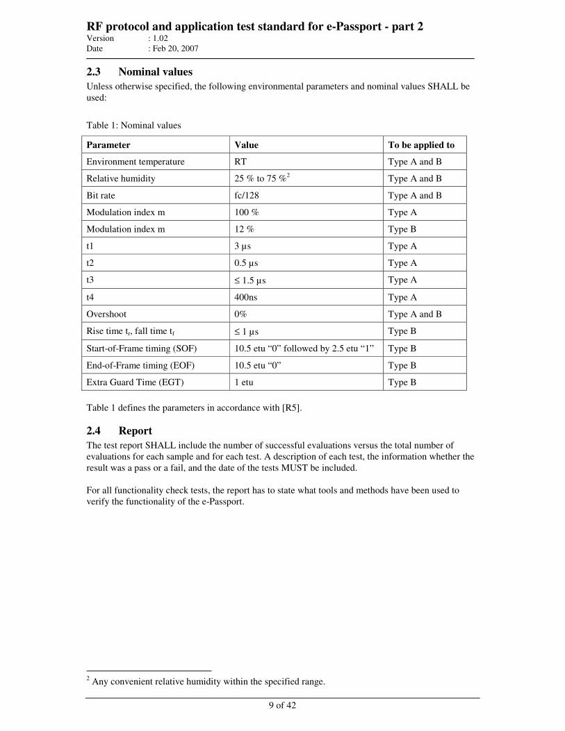
RF protocol and application test standard for e-Passport - part 2 Version : 1.02
Date : Feb 20, 2007
9 of 42
2.3 Nominal values
Unless otherwise specified, the following environmental parameters and nominal values SHALL be
used:
Table 1: Nominal values
Parameter Value To be applied to
Environment temperature RT Type A and B
Relative humidity 25 % to 75 %2 Type A and B
Bit rate fc/128 Type A and B
Modulation index m 100 % Type A
Modulation index m 12 % Type B
t1 3 µs Type A
t2 0.5 µs Type A
t3 ≤ 1.5 µs Type A
t4 400ns Type A
Overshoot 0% Type A and B
Rise time tr, fall time tf ≤ 1 µs Type B
Start-of-Frame timing (SOF) 10.5 etu “0” followed by 2.5 etu “1” Type B
End-of-Frame timing (EOF) 10.5 etu “0” Type B
Extra Guard Time (EGT) 1 etu Type B
Table 1 defines the parameters in accordance with [R5].
2.4 Report
The test report SHALL include the number of successful evaluations versus the total number of
evaluations for each sample and for each test. A description of each test, the information whether the
result was a pass or a fail, and the date of the tests MUST be included.
For all functionality check tests, the report has to state what tools and methods have been used to
verify the functionality of the e-Passport.
2 Any convenient relative humidity within the specified range.
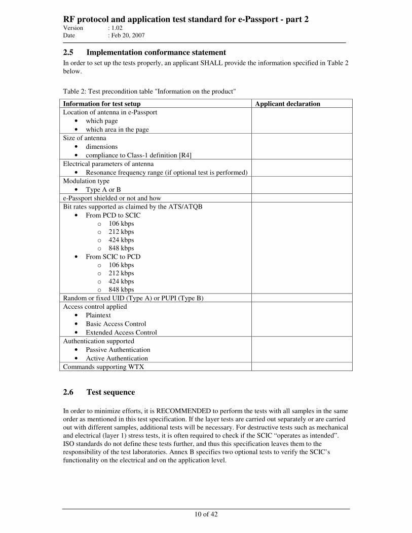
RF protocol and application test standard for e-Passport - part 2 Version : 1.02
Date : Feb 20, 2007
10 of 42
2.5 Implementation conformance statement
In order to set up the tests properly, an applicant SHALL provide the information specified in Table 2
below.
Table 2: Test precondition table "Information on the product"
Information for test setup Applicant declaration
Location of antenna in e-Passport
• which page
• which area in the page
Size of antenna
• dimensions
• compliance to Class-1 definition [R4]
Electrical parameters of antenna
• Resonance frequency range (if optional test is performed)
Modulation type
• Type A or B
e-Passport shielded or not and how
Bit rates supported as claimed by the ATS/ATQB
• From PCD to SCIC
o 106 kbps
o 212 kbps
o 424 kbps
o 848 kbps
• From SCIC to PCD
o 106 kbps
o 212 kbps
o 424 kbps
o 848 kbps
Random or fixed UID (Type A) or PUPI (Type B)
Access control applied
• Plaintext
• Basic Access Control
• Extended Access Control
Authentication supported
• Passive Authentication
• Active Authentication
Commands supporting WTX
2.6 Test sequence
In order to minimize efforts, it is RECOMMENDED to perform the tests with all samples in the same
order as mentioned in this test specification. If the layer tests are carried out separately or are carried
out with different samples, additional tests will be necessary. For destructive tests such as mechanical
and electrical (layer 1) stress tests, it is often required to check if the SCIC “operates as intended”.
ISO standards do not define these tests further, and thus this specification leaves them to the
responsibility of the test laboratories. Annex B specifies two optional tests to verify the SCIC’s
functionality on the electrical and on the application level.
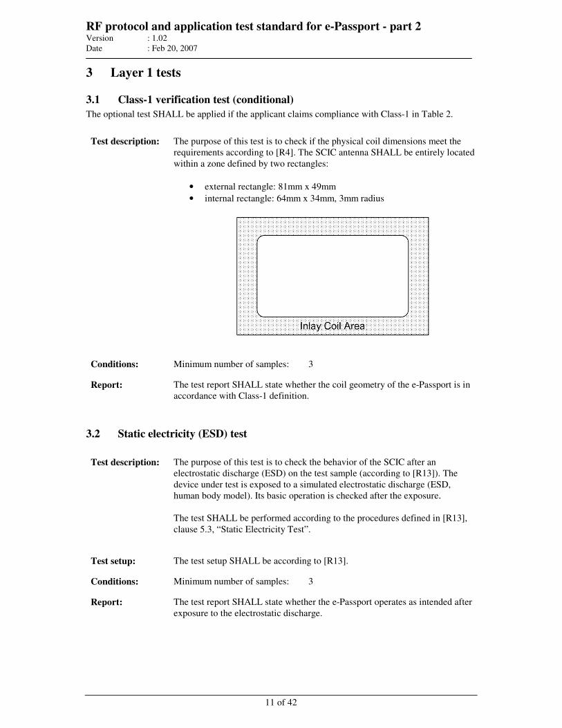
RF protocol and application test standard for e-Passport - part 2 Version : 1.02
Date : Feb 20, 2007
11 of 42
3 Layer 1 tests
3.1 Class-1 verification test (conditional)
The optional test SHALL be applied if the applicant claims compliance with Class-1 in Table 2.
Test description: The purpose of this test is to check if the physical coil dimensions meet the
requirements according to [R4]. The SCIC antenna SHALL be entirely located
within a zone defined by two rectangles:
• external rectangle: 81mm x 49mm
• internal rectangle: 64mm x 34mm, 3mm radius
Conditions: Minimum number of samples: 3
Report: The test report SHALL state whether the coil geometry of the e-Passport is in
accordance with Class-1 definition.
3.2 Static electricity (ESD) test
Test description: The purpose of this test is to check the behavior of the SCIC after an
electrostatic discharge (ESD) on the test sample (according to [R13]). The
device under test is exposed to a simulated electrostatic discharge (ESD,
human body model). Its basic operation is checked after the exposure.
The test SHALL be performed according to the procedures defined in [R13],
clause 5.3, “Static Electricity Test”.
Test setup: The test setup SHALL be according to [R13].
Conditions: Minimum number of samples: 3
Report: The test report SHALL state whether the e-Passport operates as intended after
exposure to the electrostatic discharge.
RF protocol and application test standard for e-Passport - part 2 Version : 1.02
Date : Feb 20, 2007
12 of 42
3.3 Alternating magnetic field test
Test description: The purpose of this test is to check the behavior of the e-Passport in relation to
alternating magnetic field exposure according to [R13].
Alternating magnetic field SHALL be tested at 13.56 MHz. No tests are
required at other frequencies.
Perform the test according to the test procedure defined in [R13], clause 5.1.2
“Alternating magnetic field; 12A/m test”.
Test setup: The test PCD assembly according to [R10] SHALL be used.
Conditions: Minimum number of samples: 3
Parameters: Field strength: 0 A/m, 10 A/m, 12A/m
Report: The test report SHALL state whether the e-Passport operates as intended after
exposure to an alternating magnetic field.
4 Layer 2 tests
Combinations of the following layer 2 and 3 tests are possible if it does not test influence the
coverage; e.g. combining the frame delay time test with the operating field strength test or the
operating field strength test with testing the load modulation amplitude is possible.
4.1 Load modulation amplitude test
Test description: The purpose of this test is to determine the load modulation amplitude of the e-
Passport according to [R12] (amplitude [mV] ≥ 30/H1.2 mVpeak). Perform the
test according to Figure 1 below.
For a detailed description of the load modulation test, see
• ISO/IEC 14443-2 Load modulation (30/H1.2
mVpeak) [R5]
• ISO/IEC 10373-6 AM2, PICC load modulation amplitude [R12]
Test setup: For this test, it is RECOMMENDED to have signal patterns that start with the
RF off, and then produce an unmodulated field with nominal 13.56MHz carrier
at the field level required by the test for 5ms prior to modulating this field with a
REQA or REQB command according to the used type. The nominal 13.56 MHz
carrier SHALL continue without modulation following the command for a
RECOMMENDED one second.
It is RECOMMENDED to switch off the carrier for sufficient time before
continuing at the next field level.
For this procedure, the ISO test setup has to be used as a PCD antenna. The field
strength has to be calibrated in advance. Then, the e-Passport has to be placed at
the DUT position. Afterwards, the field strength has to be readjusted.
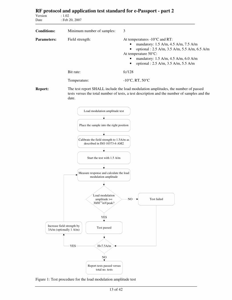
RF protocol and application test standard for e-Passport - part 2 Version : 1.02
Date : Feb 20, 2007
13 of 42
Conditions: Minimum number of samples: 3
Parameters: Field strength: At temperatures -10°C and RT:
• mandatory: 1.5 A/m, 4.5 A/m, 7.5 A/m
• optional : 2.5 A/m, 3.5 A/m, 5.5 A/m, 6.5 A/m
At temperature 50°C:
• mandatory: 1.5 A/m, 4.5 A/m, 6.0 A/m
• optional : 2.5 A/m, 3.5 A/m, 5.5 A/m
Bit rate: fc/128
Temperature: -10°C, RT, 50°C
Report: The test report SHALL include the load modulation amplitudes, the number of passed
tests versus the total number of tests, a test description and the number of samples and the
date.
Load modulation amplitude test
Place the sample into the right position
Calibrate the field strength to 1.5A/m as
described in ISO 10373-6 AM2
Measure response and calculate the load
modulation amplitude
Report tests passed versus
total no. tests
Load modulation
amplitude >=
30/H1.2
mVpeak?
H<7.5A/m
Test failedNO
YES
Increase field strength by
3A/m (optionally 1 A/m)
YES
NO
Test passed
Start the test with 1.5 A/m
Figure 1: Test procedure for the load modulation amplitude test
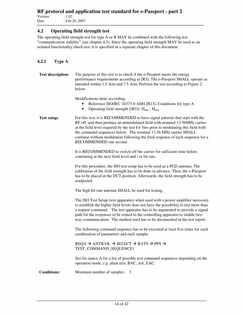
RF protocol and application test standard for e-Passport - part 2 Version : 1.02
Date : Feb 20, 2007
14 of 42
4.2 Operating field strength test
The operating field strength test for type A or B MAY be combined with the following test
“communication stability” (see chapter 4.3). Since the operating field strength MAY be used as an
isolated functionality check test, it is specified in a separate chapter of this document.
4.2.1 Type A
Test description: The purpose of this test is to check if the e-Passport meets the energy
performance requirements according to [R5]. The e-Passport SHALL operate as
intended within 1.5 A/m and 7.5 A/m. Perform the test according to Figure 2
below.
Modifications done according:
• Reference ISO/IEC 10373-6 AM4 [R13], Conditions for type A
• Operating field strength ([R5]): Hmin - Hmax
Test setup: For this test, it is RECOMMENDED to have signal patterns that start with the
RF off, and then produce an unmodulated field with nominal 13.56MHz carrier
at the field level required by the test for 5ms prior to modulating this field with
the command sequences below. The nominal 13.56 MHz carrier SHALL
continue without modulation following the final response of each sequence for a
RECOMMENDED one second.
It is RECOMMENDED to switch off the carrier for sufficient time before
continuing at the next field level and / or bit rate.
For this procedure, the ISO test setup has to be used as a PCD antenna. The
calibration of the field strength has to be done in advance. Then, the e-Passport
has to be placed at the DUT position. Afterwards, the field strength has to be
readjusted.
The high bit rate antenna SHALL be used for testing.
The ISO Test Setup (test apparatus) when used with a power amplifier necessary
to establish the higher field levels does not have the possibility to test more than
a request command. The test apparatus has to be augmented to provide a signal
path for the responses to be routed to the controlling apparatus to enable two-
way communication. The method used has to be documented in the test report.
The following command sequence has to be executed at least five times for each
combination of parameters and each sample:
REQA ANTICOL SELECT RATS PPS
TEST_COMMAND_SEQUENCE1
See for annex A for a list of possible test command sequences depending on the
operation mode, e.g. plain text, BAC, AA, EAC.
Conditions: Minimum number of samples:
3
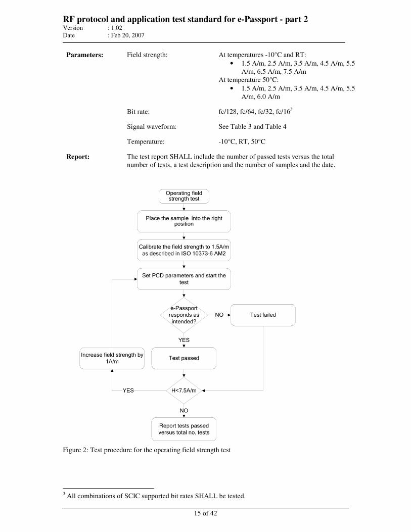
RF protocol and application test standard for e-Passport - part 2 Version : 1.02
Date : Feb 20, 2007
15 of 42
Parameters: Field strength: At temperatures -10°C and RT:
• 1.5 A/m, 2.5 A/m, 3.5 A/m, 4.5 A/m, 5.5
A/m, 6.5 A/m, 7.5 A/m
At temperature 50°C:
• 1.5 A/m, 2.5 A/m, 3.5 A/m, 4.5 A/m, 5.5
A/m, 6.0 A/m
Bit rate: fc/128, fc/64, fc/32, fc/163
Signal waveform: See Table 3 and Table 4
Temperature: -10°C, RT, 50°C
Report: The test report SHALL include the number of passed tests versus the total
number of tests, a test description and the number of samples and the date.
Operating field strength test
Place the sample into the right position
Calibrate the field strength to 1.5A/m as described in ISO 10373-6 AM2
Set PCD parameters and start the
test
Report tests passed versus total no. tests
e-Passport responds as intended?
H<7.5A/m
Test failedNO
YES
Increase field strength by 1A/m
YES
NO
Test passed
Figure 2: Test procedure for the operating field strength test
3 All combinations of SCIC supported bit rates SHALL be tested.
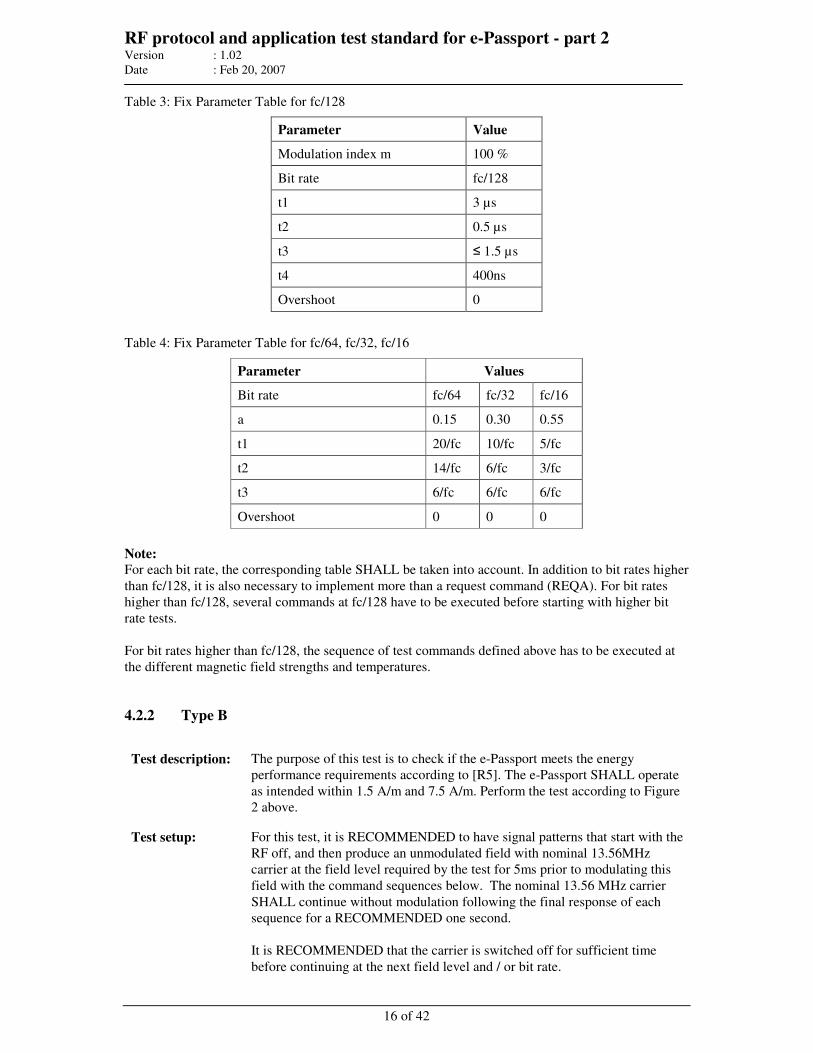
RF protocol and application test standard for e-Passport - part 2 Version : 1.02
Date : Feb 20, 2007
16 of 42
Table 3: Fix Parameter Table for fc/128
Parameter Value
Modulation index m 100 %
Bit rate fc/128
t1 3 µs
t2 0.5 µs
t3 ≤ 1.5 µs
t4 400ns
Overshoot 0
Table 4: Fix Parameter Table for fc/64, fc/32, fc/16
Parameter Values
Bit rate fc/64 fc/32 fc/16
a 0.15 0.30 0.55
t1 20/fc 10/fc 5/fc
t2 14/fc 6/fc 3/fc
t3 6/fc 6/fc 6/fc
Overshoot 0 0 0
Note:
For each bit rate, the corresponding table SHALL be taken into account. In addition to bit rates higher
than fc/128, it is also necessary to implement more than a request command (REQA). For bit rates
higher than fc/128, several commands at fc/128 have to be executed before starting with higher bit
rate tests.
For bit rates higher than fc/128, the sequence of test commands defined above has to be executed at
the different magnetic field strengths and temperatures.
4.2.2 Type B
Test description: The purpose of this test is to check if the e-Passport meets the energy
performance requirements according to [R5]. The e-Passport SHALL operate
as intended within 1.5 A/m and 7.5 A/m. Perform the test according to Figure
2 above.
Test setup: For this test, it is RECOMMENDED to have signal patterns that start with the
RF off, and then produce an unmodulated field with nominal 13.56MHz
carrier at the field level required by the test for 5ms prior to modulating this
field with the command sequences below. The nominal 13.56 MHz carrier
SHALL continue without modulation following the final response of each
sequence for a RECOMMENDED one second.
It is RECOMMENDED that the carrier is switched off for sufficient time
before continuing at the next field level and / or bit rate.
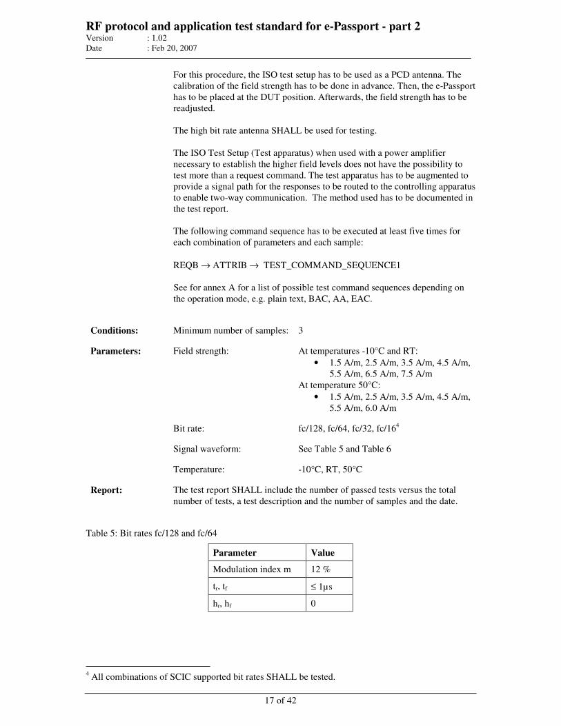
RF protocol and application test standard for e-Passport - part 2 Version : 1.02
Date : Feb 20, 2007
17 of 42
For this procedure, the ISO test setup has to be used as a PCD antenna. The
calibration of the field strength has to be done in advance. Then, the e-Passport
has to be placed at the DUT position. Afterwards, the field strength has to be
readjusted.
The high bit rate antenna SHALL be used for testing.
The ISO Test Setup (Test apparatus) when used with a power amplifier
necessary to establish the higher field levels does not have the possibility to
test more than a request command. The test apparatus has to be augmented to
provide a signal path for the responses to be routed to the controlling apparatus
to enable two-way communication. The method used has to be documented in
the test report.
The following command sequence has to be executed at least five times for
each combination of parameters and each sample:
REQB → ATTRIB → TEST_COMMAND_SEQUENCE1
See for annex A for a list of possible test command sequences depending on
the operation mode, e.g. plain text, BAC, AA, EAC.
Conditions: Minimum number of samples: 3
Field strength: At temperatures -10°C and RT:
• 1.5 A/m, 2.5 A/m, 3.5 A/m, 4.5 A/m,
5.5 A/m, 6.5 A/m, 7.5 A/m
At temperature 50°C:
• 1.5 A/m, 2.5 A/m, 3.5 A/m, 4.5 A/m,
5.5 A/m, 6.0 A/m
Parameters:
Bit rate: fc/128, fc/64, fc/32, fc/164
Signal waveform: See Table 5 and Table 6
Temperature: -10°C, RT, 50°C
Report: The test report SHALL include the number of passed tests versus the total
number of tests, a test description and the number of samples and the date.
Table 5: Bit rates fc/128 and fc/64
Parameter Value
Modulation index m 12 %
tr, tf ≤ 1µs
hr, hf 0
4 All combinations of SCIC supported bit rates SHALL be tested.
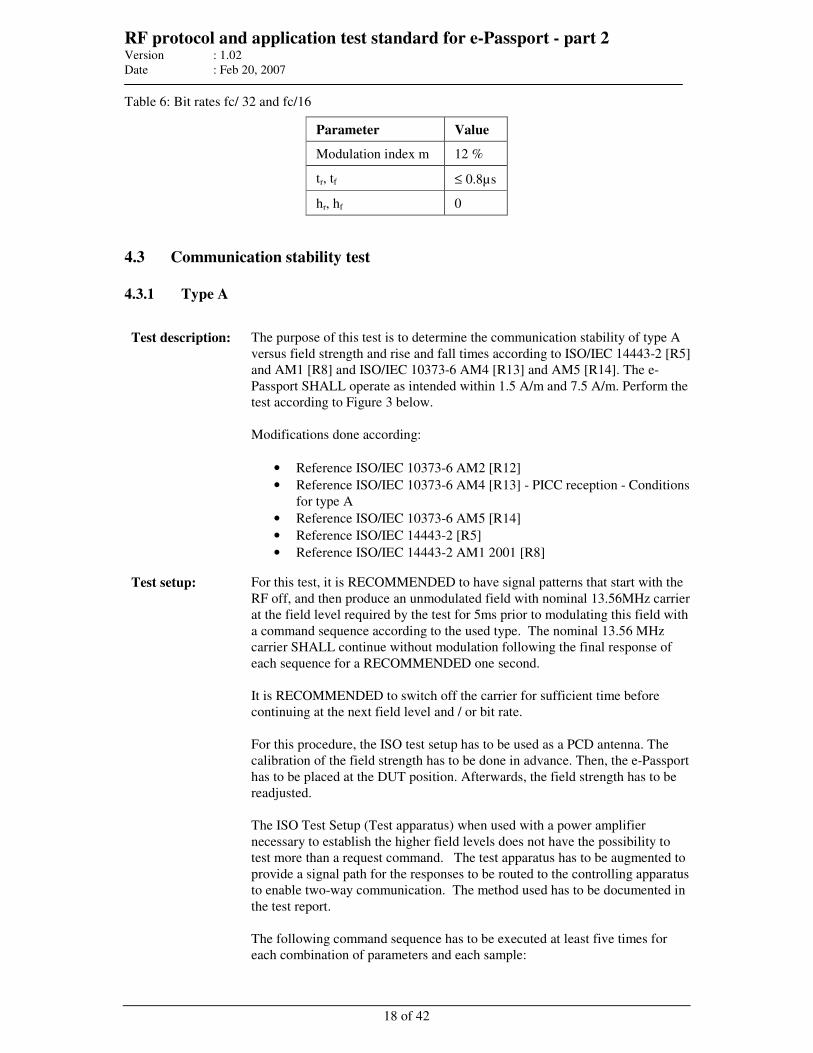
RF protocol and application test standard for e-Passport - part 2 Version : 1.02
Date : Feb 20, 2007
18 of 42
Table 6: Bit rates fc/ 32 and fc/16
Parameter Value
Modulation index m 12 %
tr, tf ≤ 0.8µs
hr, hf 0
4.3 Communication stability test
4.3.1 Type A
Test description: The purpose of this test is to determine the communication stability of type A
versus field strength and rise and fall times according to ISO/IEC 14443-2 [R5]
and AM1 [R8] and ISO/IEC 10373-6 AM4 [R13] and AM5 [R14]. The e-
Passport SHALL operate as intended within 1.5 A/m and 7.5 A/m. Perform the
test according to Figure 3 below.
Modifications done according:
• Reference ISO/IEC 10373-6 AM2 [R12]
• Reference ISO/IEC 10373-6 AM4 [R13] - PICC reception - Conditions
for type A
• Reference ISO/IEC 10373-6 AM5 [R14]
• Reference ISO/IEC 14443-2 [R5]
• Reference ISO/IEC 14443-2 AM1 2001 [R8]
Test setup: For this test, it is RECOMMENDED to have signal patterns that start with the
RF off, and then produce an unmodulated field with nominal 13.56MHz carrier
at the field level required by the test for 5ms prior to modulating this field with
a command sequence according to the used type. The nominal 13.56 MHz
carrier SHALL continue without modulation following the final response of
each sequence for a RECOMMENDED one second.
It is RECOMMENDED to switch off the carrier for sufficient time before
continuing at the next field level and / or bit rate.
For this procedure, the ISO test setup has to be used as a PCD antenna. The
calibration of the field strength has to be done in advance. Then, the e-Passport
has to be placed at the DUT position. Afterwards, the field strength has to be
readjusted.
The ISO Test Setup (Test apparatus) when used with a power amplifier
necessary to establish the higher field levels does not have the possibility to
test more than a request command. The test apparatus has to be augmented to
provide a signal path for the responses to be routed to the controlling apparatus
to enable two-way communication. The method used has to be documented in
the test report.
The following command sequence has to be executed at least five times for
each combination of parameters and each sample:
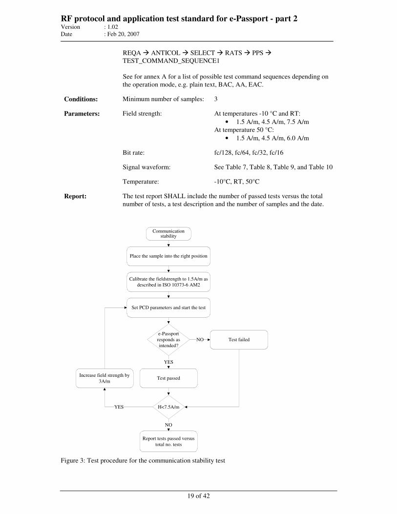
RF protocol and application test standard for e-Passport - part 2 Version : 1.02
Date : Feb 20, 2007
19 of 42
REQA ANTICOL SELECT RATS PPS
TEST_COMMAND_SEQUENCE1
See for annex A for a list of possible test command sequences depending on
the operation mode, e.g. plain text, BAC, AA, EAC.
Conditions: Minimum number of samples: 3
Parameters: Field strength: At temperatures -10 °C and RT:
• 1.5 A/m, 4.5 A/m, 7.5 A/m
At temperature 50 °C:
• 1.5 A/m, 4.5 A/m, 6.0 A/m
Bit rate: fc/128, fc/64, fc/32, fc/16
Signal waveform: See Table 7, Table 8, Table 9, and Table 10
Temperature: -10°C, RT, 50°C
Report: The test report SHALL include the number of passed tests versus the total
number of tests, a test description and the number of samples and the date.
Communication
stability
Place the sample into the right position
Calibrate the fieldstrength to 1.5A/m as
described in ISO 10373-6 AM2
Set PCD parameters and start the test
Report tests passed versus
total no. tests
e-Passport
responds as
intended?
H<7.5A/m
Test failedNO
YES
Increase field strength by
3A/m
YES
NO
Test passed
Figure 3: Test procedure for the communication stability test
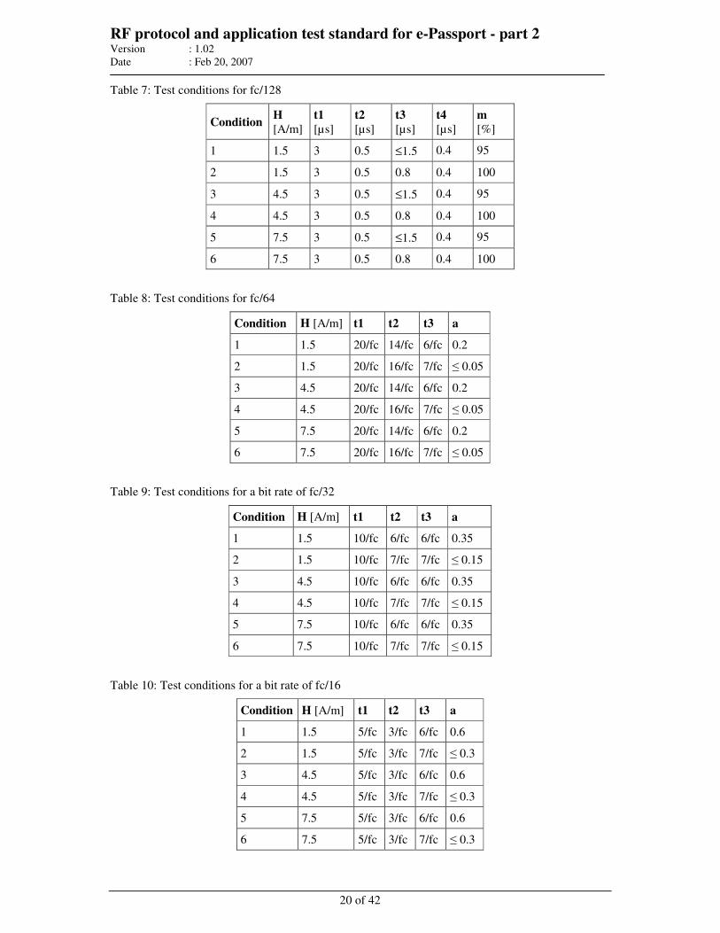
RF protocol and application test standard for e-Passport - part 2 Version : 1.02
Date : Feb 20, 2007
20 of 42
Table 7: Test conditions for fc/128
Condition H
[A/m]
t1
[µs]
t2
[µs]
t3
[µs]
t4
[µs]
m
[%]
1 1.5 3 0.5 ≤1.5 0.4 95
2 1.5 3 0.5 0.8 0.4 100
3 4.5 3 0.5 ≤1.5 0.4 95
4 4.5 3 0.5 0.8 0.4 100
5 7.5 3 0.5 ≤1.5 0.4 95
6 7.5 3 0.5 0.8 0.4 100
Table 8: Test conditions for fc/64
Condition H [A/m] t1 t2 t3 a
1 1.5 20/fc 14/fc 6/fc 0.2
2 1.5 20/fc 16/fc 7/fc ≤ 0.05
3 4.5 20/fc 14/fc 6/fc 0.2
4 4.5 20/fc 16/fc 7/fc ≤ 0.05
5 7.5 20/fc 14/fc 6/fc 0.2
6 7.5 20/fc 16/fc 7/fc ≤ 0.05
Table 9: Test conditions for a bit rate of fc/32
Condition H [A/m] t1 t2 t3 a
1 1.5 10/fc 6/fc 6/fc 0.35
2 1.5 10/fc 7/fc 7/fc ≤ 0.15
3 4.5 10/fc 6/fc 6/fc 0.35
4 4.5 10/fc 7/fc 7/fc ≤ 0.15
5 7.5 10/fc 6/fc 6/fc 0.35
6 7.5 10/fc 7/fc 7/fc ≤ 0.15
Table 10: Test conditions for a bit rate of fc/16
Condition H [A/m] t1 t2 t3 a
1 1.5 5/fc 3/fc 6/fc 0.6
2 1.5 5/fc 3/fc 7/fc ≤ 0.3
3 4.5 5/fc 3/fc 6/fc 0.6
4 4.5 5/fc 3/fc 7/fc ≤ 0.3
5 7.5 5/fc 3/fc 6/fc 0.6
6 7.5 5/fc 3/fc 7/fc ≤ 0.3
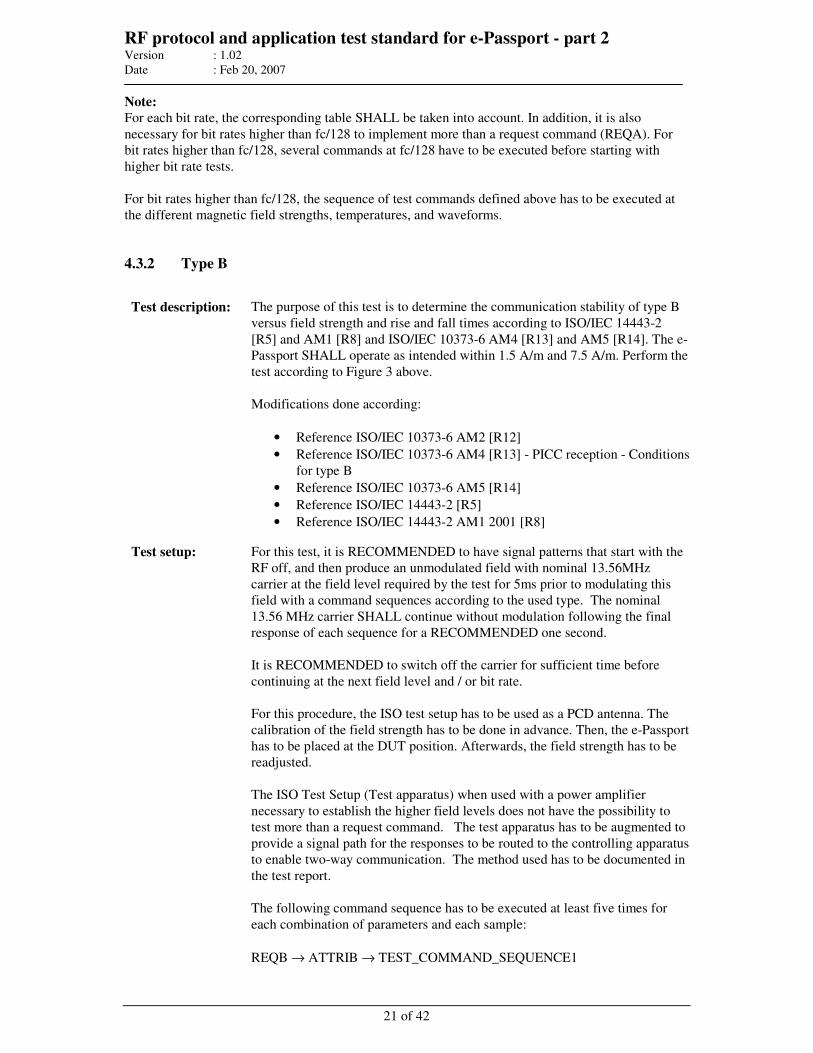
RF protocol and application test standard for e-Passport - part 2 Version : 1.02
Date : Feb 20, 2007
21 of 42
Note:
For each bit rate, the corresponding table SHALL be taken into account. In addition, it is also
necessary for bit rates higher than fc/128 to implement more than a request command (REQA). For
bit rates higher than fc/128, several commands at fc/128 have to be executed before starting with
higher bit rate tests.
For bit rates higher than fc/128, the sequence of test commands defined above has to be executed at
the different magnetic field strengths, temperatures, and waveforms.
4.3.2 Type B
Test description: The purpose of this test is to determine the communication stability of type B
versus field strength and rise and fall times according to ISO/IEC 14443-2
[R5] and AM1 [R8] and ISO/IEC 10373-6 AM4 [R13] and AM5 [R14]. The e-
Passport SHALL operate as intended within 1.5 A/m and 7.5 A/m. Perform the
test according to Figure 3 above.
Modifications done according:
• Reference ISO/IEC 10373-6 AM2 [R12]
• Reference ISO/IEC 10373-6 AM4 [R13] - PICC reception - Conditions
for type B
• Reference ISO/IEC 10373-6 AM5 [R14]
• Reference ISO/IEC 14443-2 [R5]
• Reference ISO/IEC 14443-2 AM1 2001 [R8]
Test setup: For this test, it is RECOMMENDED to have signal patterns that start with the
RF off, and then produce an unmodulated field with nominal 13.56MHz
carrier at the field level required by the test for 5ms prior to modulating this
field with a command sequences according to the used type. The nominal
13.56 MHz carrier SHALL continue without modulation following the final
response of each sequence for a RECOMMENDED one second.
It is RECOMMENDED to switch off the carrier for sufficient time before
continuing at the next field level and / or bit rate.
For this procedure, the ISO test setup has to be used as a PCD antenna. The
calibration of the field strength has to be done in advance. Then, the e-Passport
has to be placed at the DUT position. Afterwards, the field strength has to be
readjusted.
The ISO Test Setup (Test apparatus) when used with a power amplifier
necessary to establish the higher field levels does not have the possibility to
test more than a request command. The test apparatus has to be augmented to
provide a signal path for the responses to be routed to the controlling apparatus
to enable two-way communication. The method used has to be documented in
the test report.
The following command sequence has to be executed at least five times for
each combination of parameters and each sample:
REQB → ATTRIB → TEST_COMMAND_SEQUENCE1
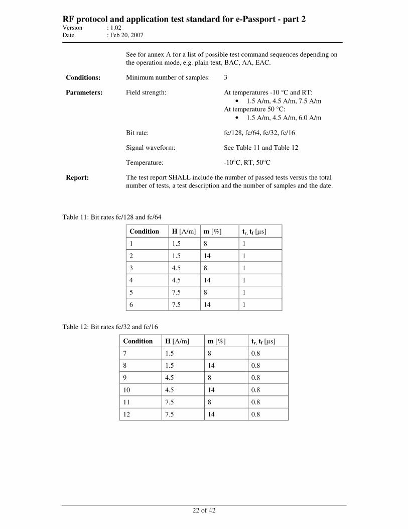
RF protocol and application test standard for e-Passport - part 2 Version : 1.02
Date : Feb 20, 2007
22 of 42
See for annex A for a list of possible test command sequences depending on
the operation mode, e.g. plain text, BAC, AA, EAC.
Conditions: Minimum number of samples: 3
Parameters: Field strength: At temperatures -10 °C and RT:
• 1.5 A/m, 4.5 A/m, 7.5 A/m
At temperature 50 °C:
• 1.5 A/m, 4.5 A/m, 6.0 A/m
Bit rate: fc/128, fc/64, fc/32, fc/16
Signal waveform: See Table 11 and Table 12
Temperature: -10°C, RT, 50°C
Report: The test report SHALL include the number of passed tests versus the total
number of tests, a test description and the number of samples and the date.
Table 11: Bit rates fc/128 and fc/64
Condition H [A/m] m [%] tr, tf [µs]
1 1.5 8 1
2 1.5 14 1
3 4.5 8 1
4 4.5 14 1
5 7.5 8 1
6 7.5 14 1
Table 12: Bit rates fc/32 and fc/16
Condition H [A/m] m [%] tr, tf [µs]
7 1.5 8 0.8
8 1.5 14 0.8
9 4.5 8 0.8
10 4.5 14 0.8
11 7.5 8 0.8
12 7.5 14 0.8
RF protocol and application test standard for e-Passport - part 2 Version : 1.02
Date : Feb 20, 2007
23 of 42
4.4 Resonance frequency test (optional)
Test description: The purpose of this test is to determine the resonance frequency of the e-
Passport. The resonance frequency SHALL be within the range that has been
specified in the implementation conformance specification.
Test setup: An LCR meter MAY be used: a coil that is connected to the device’s output
generates the magnetic field. The setup SHALL be calibrated in advance. The
e-Passport coil SHALL be positioned in a close distance concentrically above
the field-generating coil.
The resonance frequency is defined as the frequency, where the real part of the
field generating coil impedance reaches its maximum under threshold
conditions of the e-Passport.
Conditions: Minimum number of samples: 3
Parameters: Temperature: RT
Report: The test report SHALL state whether the resonance frequencies measured are
within the specified range of resonance frequencies.
RF protocol and application test standard for e-Passport - part 2 Version : 1.02
Date : Feb 20, 2007
24 of 42
5 Layer 3 timing and framing tests
Test Setup:
Setup as defined for the electrical tests can be used also for timing and framing tests. However, the
test laboratory can select an alternative setup for the timing and framing related tests, as long as the
setup meets the specified parameters of the test signal. Independently of the selected test setup, the
setup is called “test apparatus” in this clause.
The Test apparatus SHALL be able to emulate the protocol, to measure and monitor the timing of the
logical Input/Receive line relative to the CLK frequency, and to be able to analyze the I/O-bit stream
in accordance with the protocol.
All tests SHALL be performed with one specific field strength between 1.5 A/m and 7.5 A/m if not
further specified. All tests SHALL be performed at RT if not further specified.
5.1 Startup time - Polling
5.1.1 Type A
Test description: The purpose of this test is to check the correct behavior after switching the
RF field on and during alternate receiving of REQB and REQA (polling).
Perform test as defined in ISO 10373-6 AM1, Annex G 3.2 [R11] but
change the time parameter in steps 4, 8 and 9 to 10 ms.
The e-Passport SHALL respond to a REQA 10 ms after switching on the
RF field and it SHALL respond to a REQA 10 ms after an REQB.
Conditions: Minimum number of samples: 3
Parameters: Bit rate: fc/128
Report: The test report SHALL state whether the e-Passport meets the startup
timing requirements.
5.1.2 Type B
Test description: The purpose of this test is to check the correct behavior after switching the
RF field on and during alternate receiving of REQA and REQB (polling).
Perform test as defined in ISO 10373-6 AM1, Annex G 4.2 [R11] but
change the time parameter in steps 4, 8 and 9 to 10 ms.
The e-Passport SHALL respond to a REQB 10 ms after switching on the
RF field and it SHALL respond to a REQB 10 ms after an REQA.
Conditions: Minimum number of samples: 3
Parameters: Bit rate: fc/128
RF protocol and application test standard for e-Passport - part 2 Version : 1.02
Date : Feb 20, 2007
25 of 42
Report: The test report SHALL state whether the e-Passport meets the startup
timing requirements.
5.2 Frame delay time (type A only)
Test description: This test shall check if the frame delay time (FDT) is correct. The purpose of
this test is to determine the FDT of the e-Passport according to ISO 10373-6
AM1 [R11].
Modifications done according:
• Reference ISO/IEC 14443-3 [R6], Frame delay time PCD to PICC
• Reference ISO/IEC 14443-3 AM1 [R9]
Perform test as defined in ISO 10373-6 AM1, scenario 2 of Annex G 3.4
[R11]. Check the FDT of the SCIC response frame.
Depending on the last bit of the command the FDT SHALL be as follows:
(1)b FDT = 1236 / fc
(0)b FDT = 1172 / fc
Conditions: Minimum number of samples: 3
Parameters: Bit rate: fc/128
Report: The test report SHALL state whether the e-Passport meets the requirements
concerning FDT timing.
5.3 Start-Of-Frame and End-Of-Frame timing (type B only)
Test description: The purpose of this test is to check whether the e-Passport meets the SOF and
EOF timing requirements according to Annex G of [R11].
Perform test for each condition as defined in ISO 10373-6 AM1, Annex G 4.3
[R11]. Set the frame parameters of the test apparatus according to the
conditions defined in Table 13 and Table 14. Check the values SOF and EOF
of the SCIC response frame.
The values of SOF and EOF SHALL conform to the following:
• SOF logic 0 timing SHALL be between 10 and 11 etu.
• SOF logic 1 timing SHALL be between 2 and 3 etu.
• EOF logic 0 timing shall be between 10 and 11 etu.
Conditions: Minimum number of samples: 3
Parameters: Bit rate: fc/128
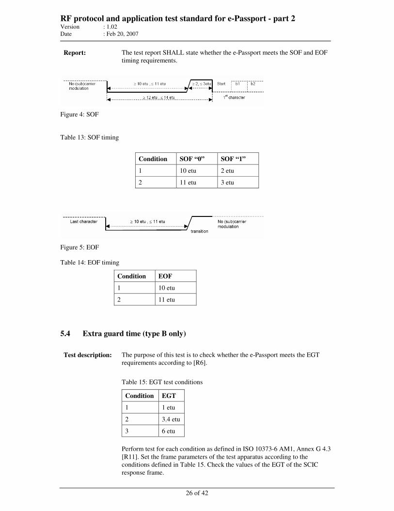
RF protocol and application test standard for e-Passport - part 2 Version : 1.02
Date : Feb 20, 2007
26 of 42
Report: The test report SHALL state whether the e-Passport meets the SOF and EOF
timing requirements.
Figure 4: SOF
Table 13: SOF timing
Condition SOF “0” SOF “1”
1 10 etu 2 etu
2 11 etu 3 etu
Figure 5: EOF
Table 14: EOF timing
Condition EOF
1 10 etu
2 11 etu
5.4 Extra guard time (type B only)
Test description: The purpose of this test is to check whether the e-Passport meets the EGT
requirements according to [R6].
Table 15: EGT test conditions
Condition EGT
1 1 etu
2 3.4 etu
3 6 etu
Perform test for each condition as defined in ISO 10373-6 AM1, Annex G 4.3
[R11]. Set the frame parameters of the test apparatus according to the
conditions defined in Table 15. Check the values of the EGT of the SCIC
response frame.
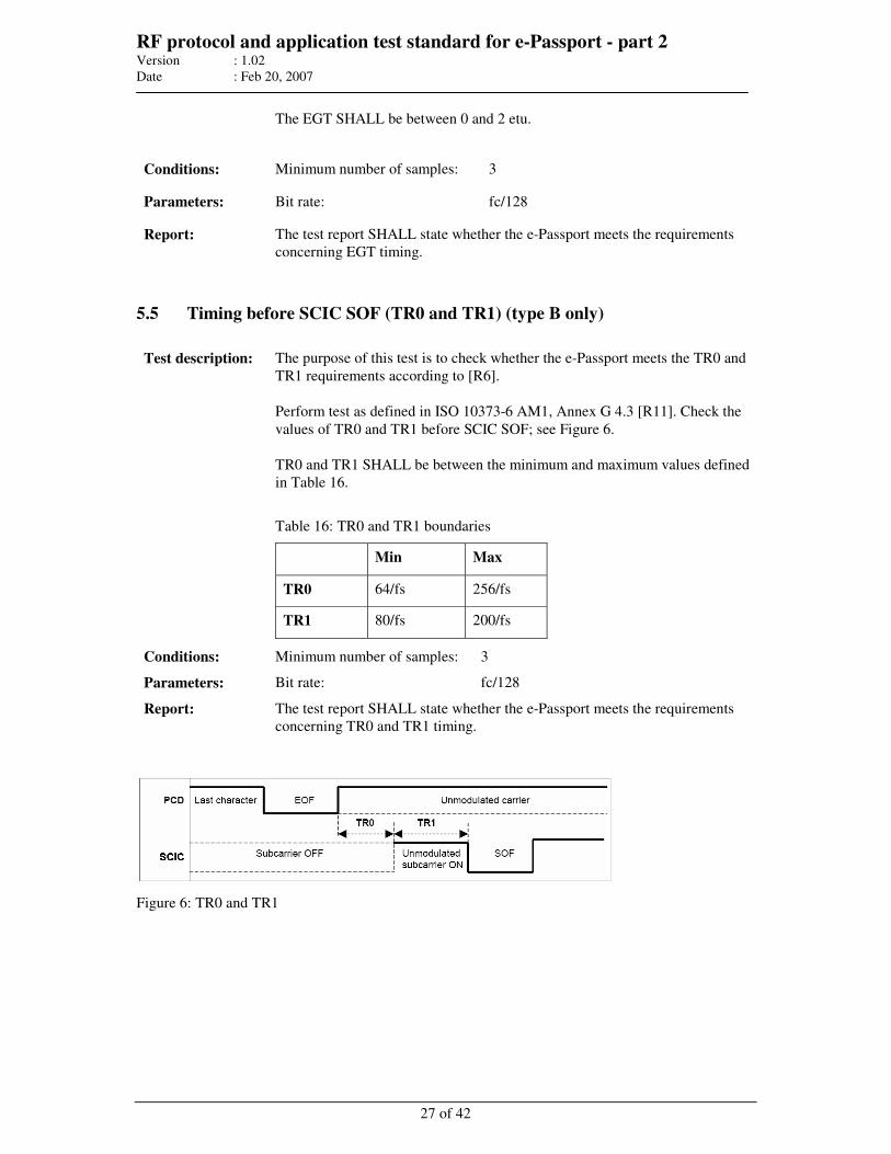
RF protocol and application test standard for e-Passport - part 2 Version : 1.02
Date : Feb 20, 2007
27 of 42
The EGT SHALL be between 0 and 2 etu.
Conditions: Minimum number of samples: 3
Parameters: Bit rate: fc/128
Report: The test report SHALL state whether the e-Passport meets the requirements
concerning EGT timing.
5.5 Timing before SCIC SOF (TR0 and TR1) (type B only)
Test description: The purpose of this test is to check whether the e-Passport meets the TR0 and
TR1 requirements according to [R6].
Perform test as defined in ISO 10373-6 AM1, Annex G 4.3 [R11]. Check the
values of TR0 and TR1 before SCIC SOF; see Figure 6.
TR0 and TR1 SHALL be between the minimum and maximum values defined
in Table 16.
Table 16: TR0 and TR1 boundaries
Min Max
TR0 64/fs 256/fs
TR1 80/fs 200/fs
Conditions: Minimum number of samples: 3
Parameters: Bit rate: fc/128
Report: The test report SHALL state whether the e-Passport meets the requirements
concerning TR0 and TR1 timing.
Figure 6: TR0 and TR1
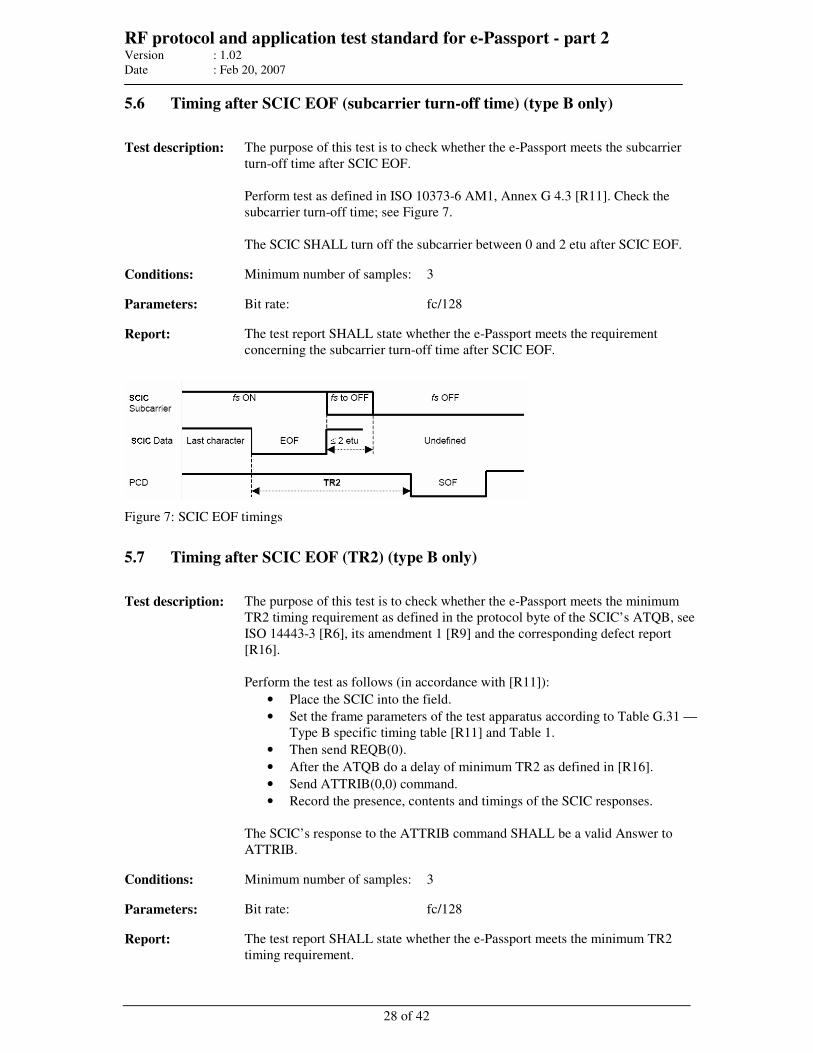
RF protocol and application test standard for e-Passport - part 2 Version : 1.02
Date : Feb 20, 2007
28 of 42
5.6 Timing after SCIC EOF (subcarrier turn-off time) (type B only)
Test description: The purpose of this test is to check whether the e-Passport meets the subcarrier
turn-off time after SCIC EOF.
Perform test as defined in ISO 10373-6 AM1, Annex G 4.3 [R11]. Check the
subcarrier turn-off time; see Figure 7.
The SCIC SHALL turn off the subcarrier between 0 and 2 etu after SCIC EOF.
Conditions: Minimum number of samples: 3
Parameters: Bit rate: fc/128
Report: The test report SHALL state whether the e-Passport meets the requirement
concerning the subcarrier turn-off time after SCIC EOF.
Figure 7: SCIC EOF timings
5.7 Timing after SCIC EOF (TR2) (type B only)
Test description: The purpose of this test is to check whether the e-Passport meets the minimum
TR2 timing requirement as defined in the protocol byte of the SCIC’s ATQB, see
ISO 14443-3 [R6], its amendment 1 [R9] and the corresponding defect report
[R16].
Perform the test as follows (in accordance with [R11]):
• Place the SCIC into the field.
• Set the frame parameters of the test apparatus according to Table G.31 —
Type B specific timing table [R11] and Table 1.
• Then send REQB(0).
• After the ATQB do a delay of minimum TR2 as defined in [R16].
• Send ATTRIB(0,0) command.
• Record the presence, contents and timings of the SCIC responses.
The SCIC’s response to the ATTRIB command SHALL be a valid Answer to
ATTRIB.
Conditions: Minimum number of samples: 3
Parameters: Bit rate: fc/128
Report: The test report SHALL state whether the e-Passport meets the minimum TR2
timing requirement.
RF protocol and application test standard for e-Passport - part 2 Version : 1.02
Date : Feb 20, 2007
29 of 42
6 Layer 3 and 4 protocol tests
These tests provide a basic set of tests to be performed to check the compliance to ISO/IEC 14443
protocol layers 3 [R6], [R9] and 4 [R7]. All tests are based on and SHALL be evaluated according to
the referenced versions of standards.
Test Setup:
Setup as defined for the electrical tests can be used also for protocol tests. However, the test
laboratory can select an alternative setup for the protocol related tests, as long as the setup meets the
specified parameters of the test signal. Independently of the selected test setup, the setup is called
“test apparatus” in this clause.
The Test apparatus SHALL be able to emulate the protocol, to measure and monitor the timing of the
logical Input/Receive line relative to the CLK frequency, and to be able to analyze the I/O-bit stream
in accordance with the protocol.
All tests SHALL be performed with one specific field strength between 1.5 A/m and 7.5 A/m if not
further specified. All tests SHALL be performed at RT if not further specified.
The tests are based on the ISO/IEC10373-6 AM1 specification [R11]. For the test, commands defined
in [R11] commands that are typical for an application SHOULD be used. Therefore, refer to annex A
for a list of TEST COMMANDS that MUST be used for testing the e-Passport.
RFU fields SHOULD be constantly monitored during the testing and SHALL always be verified to
contain the assigned default value in accordance with Annex G1.5 of [R11].
6.1 Type A activation
These tests SHALL ensure that the start-up and the activation are in accordance with [R6]. These
tests are split up to state transitions and the handling of RATS and PPS.
6.1.1 State transitions
Test description: The purpose of this test is to check the correct behavior during state
transitions as defined in [R6]. Additionally possible proprietary paths of the
“Select sequence flow chart” specified in [R6] MUST NOT negatively affect
the test.
Perform test as defined in ISO 10373-6 AM1, Annex G 3.4 [R11]. The tests
specified in the sub-clause “Testing of the PICC type A state transitions” of
[R11] SHALL be used. The detailed test procedure is not specified further
herein.
Report: The test report SHALL state whether the SCIC responds as indicated in the
procedures according to [R11].
RF protocol and application test standard for e-Passport - part 2 Version : 1.02
Date : Feb 20, 2007
30 of 42
6.1.2 Handling of type A anticollision
Test description: The purpose of this test is to check the correct behavior during anticollision
as defined in [R6].
Perform test as defined in ISO 10373-6 AM1, Annex G 3.5 [R11]. The tests
specified in the sub-clause “Handling of type A anticollision” of [R11]
SHALL be used. The detailed test procedure is not specified further herein.
Report: The test report SHALL state whether the SCIC responds as indicated in the
procedures according to [R11].
6.1.3 Handling of RATS
Test description: The purpose of this test is to check the correct behavior on a RATS as
defined in [R6].
Perform test as defined in ISO 10373-6 AM1, Annex G 3.6 [R11]. The tests
specified in the sub-clause “Handling of RATS” of [R11] SHALL be used
where a valid and an invalid RATS is sent. The detailed test procedure is not
further specified herein.
In addition, it SHALL be verified if the bit rates as defined in the interface
byte TA(1) of the ATS are equal to the bit rates claimed in the
implementation conformance statement.
Report: The test report SHALL state whether the SCIC responds as indicated in the
procedures according to [R11]. It SHALL state if the ATS correctly encodes
the bit rates.
6.1.4 Handling of PPS
Test description: The purpose of this test is to check the correct behavior on a PPS as defined
in [R6].
Perform test as defined in ISO 10373-6 AM1, Annex G 3.7 [R11]. The tests
specified in the sub-clause “Handling of PPS request” of [R11] SHALL be
used where a valid and an invalid PPS is sent. The detailed test procedure is
not further specified herein.
Test Scenario 17: PPS without PPS1 as defined in [R11] SHALL NOT be
performed.
Report: The test report SHALL state whether the SCIC responds as indicated in the
procedures according to [R11].
RF protocol and application test standard for e-Passport - part 2 Version : 1.02
Date : Feb 20, 2007
31 of 42
6.1.5 Handling of FSD
Test description: The purpose of this test is to check if the SCIC correctly handles FSD
negotiated by the RATS as defined in [R6].
Perform test as defined in ISO 10373-6 AM1, Annex G 3.8 [R11]. The tests
specified in the sub-clause “Handling of FSD” of [R11] SHALL be used.
The detailed test procedure is not further specified herein.
Report: The test report SHALL state whether the SCIC responds as indicated in the
procedures according to [R11].
6.2 Type B activation
The following tests regarding type B activation are required according to [R11] and SHALL ensure
that the activation is in accordance with [R6].
6.2.1 State transitions
Test description: These tests are to verify the correct implementation of a type B SCIC’s state
machine. Perform test as defined in ISO 10373-6 AM1, Annex G 4.4 [R11].
The procedure specified in “Testing of the PICC Type B State Transition” of
[R11] SHALL be used.
Report: The test report SHALL state whether the SCIC responds as indicated in the
procedures according to [R11].
6.2.2 Handling of type B anticollision
Test description: This test is to determine the handling of a SCIC type B anticollision. Perform
test as defined in ISO 10373-6 AM1, Annex G 4.5 [R11]. The procedure
specified in “Handling of Type B Anticollision” of [R11] SHALL be used.
Report: The test report SHALL state whether the SCIC responds as indicated in the
procedures according to [R11].
6.2.3 Handling of ATTRIB
Test description: This test is to determine the behavior of the SCIC type B on ATTRIB
command. Perform test as defined in ISO 10373-6 AM1, Annex G 4.6 [R11].
The procedure specified in “Handling of ATTRIB” of [R11] SHALL be used.
In addition, it SHALL be verified if the bit rates as defined in the protocol info
byte of the ATQB are equal to the bit rates claimed in the implementation
conformance statement.
Report: The test report SHALL state whether the SCIC responds as indicated in the
RF protocol and application test standard for e-Passport - part 2 Version : 1.02
Date : Feb 20, 2007
32 of 42
procedures according to [R11]. It SHALL state if the ATQB correctly encodes
the bit rates.
6.2.4 Handling of maximum frame size
Test description: The purpose of this test is to check if the SCIC correctly handles FSD
negotiated by the ATTRIB as defined in [R6]. Perform test as defined in ISO
10373-6 AM1, Annex G 4.7 [R11]. The procedure specified in “Handling of
Maximum Frame Size” of [R11] SHALL be used.
Report: The test report SHALL state whether the SCIC responds as indicated in the
procedures according to [R11].
6.3 Data exchange protocol tests
These tests SHALL ensure the logical operation is in accordance with [R7]. They are valid for both,
type A and type B, whereas the activation before running these tests is different and listed below.
All tests SHALL be performed with one specific field strength between 1.5 A/m and 7.5 A/m if not
further specified. All tests SHALL be performed at RT if not further specified.
The activation for type A SHALL be:
1. Activation using: REQA, ANTICOLISSION, SELECT as defined in [R6]
2. Activation using: RATS as defined in [R7]
3. Check that activation has been correct (response has been correct for all commands)
The activation for type B SHALL be:
1. Activation using: REQB with number of timeslots set to 0 as defined in [R6]
2. Activation using: ATTRIB as defined in [R6]
3. Check that activation has been correct (response has been correct for all commands)
6.3.1 Exchange of I-blocks
Test description: The purpose of this test is to check the correct behavior of I-blocks as
defined in [R7].
Perform tests as defined in ISO 10373-6 AM1, Annex G 5.2 [R11]. These
tests include both correct and erroneous transactions and are described in
[R7] and with the scenario caption “Exchange of I-blocks” in [R11]. The
general TEST_COMMAND1 as defined by [R11] is specified in annex A.
The detailed test procedure is not specified further herein.
Report: The test report SHALL state whether the response is in accordance with
[R7]. The report SHALL include the test commands used.
RF protocol and application test standard for e-Passport - part 2 Version : 1.02
Date : Feb 20, 2007
33 of 42
6.3.2 Chaining of I-blocks
The purpose of this test is to check the correct behavior of chained I-blocks as defined in [R7]. These
tests are divided into two parts, the first one where the PCD (Test apparatus) uses chaining and the
second one where the e-Passport uses chaining.
Test description: PCD uses chaining
The PCD chaining tests can be performed without knowing dedicated
command behavior on the device under test. The purpose of this test is to
check the correct behavior of chained I-blocks from PCD side as defined in
[R7].
Perform tests as defined in ISO 10373-6 AM1, Annex G 5.2 [R11]. These
tests include both correct and erroneous transactions and are described in
[R7] and with the scenario caption “PCD uses chaining” in [R11]. The
general TEST_COMMAND1 as defined by [R11] is specified in annex A.
The detailed test procedure is not specified further herein.
Report: The test report SHALL state whether the response is in accordance with
[R7]. The report SHALL include the test commands used.
Test description: SCIC uses chaining (optional)
The SCIC chaining is harder to achieve. If the higher layer functionality is
not known in detail (knowing a command which by default responds with a
chained block), this test can not be performed. Therefore, this test is
optional. If applicable, the general TEST_COMMAND2 as defined by [R11]
is specified in annex A.
The purpose of this test is to check the correct behavior of chained I-blocks
from SCIC side as defined in [R7].
Perform tests as defined in ISO 10373-6 AM1, Annex G 5.2 [R11]. These
tests include both correct and erroneous transactions and are described in
[R7] and with the scenario caption “PICC uses chaining” in [R11]. The
general TEST_COMMAND2 as defined by [R11] is specified in annex A.
The detailed test procedure is not specified further herein.
Report: The test report SHALL state whether the response is in accordance with
[R7]. The report SHALL include the test commands used.
RF protocol and application test standard for e-Passport - part 2 Version : 1.02
Date : Feb 20, 2007
34 of 42
6.3.3 DESELECT
.
Test description: The purpose of this test is to check the correct behavior of DESELECT as
defined in [R7].
Perform tests as defined in ISO 10373-6 AM1, Annex G 5.2 [R11]. These
tests include both correct and erroneous transactions and are described in
[R7] and with the scenario caption “DESELECT” in [R11]. The general
TEST_COMMAND1 as defined by [R11] is specified in annex A. The
detailed test procedure is not specified further herein.
Report: The test report SHALL state whether the response is in accordance with
[R7]. The report SHALL include the test commands used.
6.3.4 Request for waiting time extension (optional)
Test description: If the SCIC does not support a command which by default responds with a
waiting time extension, this test cannot be performed. Therefore, it is
optional.
The purpose of this test is to check the correct behavior of request waiting
time extension command as defined in [R7].
Perform tests as defined in ISO 10373-6 AM1, Annex G 5.2 [R11]. These
tests include both correct and erroneous transactions and are described in
[R7] and with the scenario caption “Request for waiting time extension” in
[R11]. The general TEST_COMMAND3 as defined by [R11] is specified in
annex A which by default responds with the waiting time extension
command. The detailed test procedure is not specified further herein.
Report: The test report SHALL state whether the response is in accordance with
[R7]. The report SHALL include the test commands used.
6.3.5 Handling of SCIC error detection (optional)
Test description: The purpose of this test is to check the correct behavior of the SCIC’s error
detection as defined in [R7].
Perform tests as defined in ISO 10373-6 AM1, Annex G 5.3 [R11]. The
general TEST_COMMAND1 and TEST_COMMAND3 as defined by [R11]
are specified in annex A. The detailed test procedure is not specified further
herein.
Scenarios G 53 “Bad block number on I-Block” and G 54 “Bad block
number on chained I-Block” as defined in [R11] SHOULD NOT be
performed.
Report: The test report SHALL state whether the response is in accordance with
[R7]. The report SHALL include the test commands used.
RF protocol and application test standard for e-Passport - part 2 Version : 1.02
Date : Feb 20, 2007
35 of 42
6.3.6 SCIC reaction on CID
Test description: The purpose of this test is to check the correct reaction of the SCIC to CID
coding as defined in [R7]. This test can be applied to all e-Passports even if
they do not support CID.
Perform tests as defined in ISO 10373-6 AM1, Annex G 5.4 [R11]. The
general TEST_COMMAND1, TEST_COMMAND2 and
TEST_COMMAND3 as defined by [R11] are specified in annex A. The
detailed test procedure is not specified further herein.
Report The test report SHALL state whether the response is in accordance with
[R7]. The report SHALL include the test commands used.
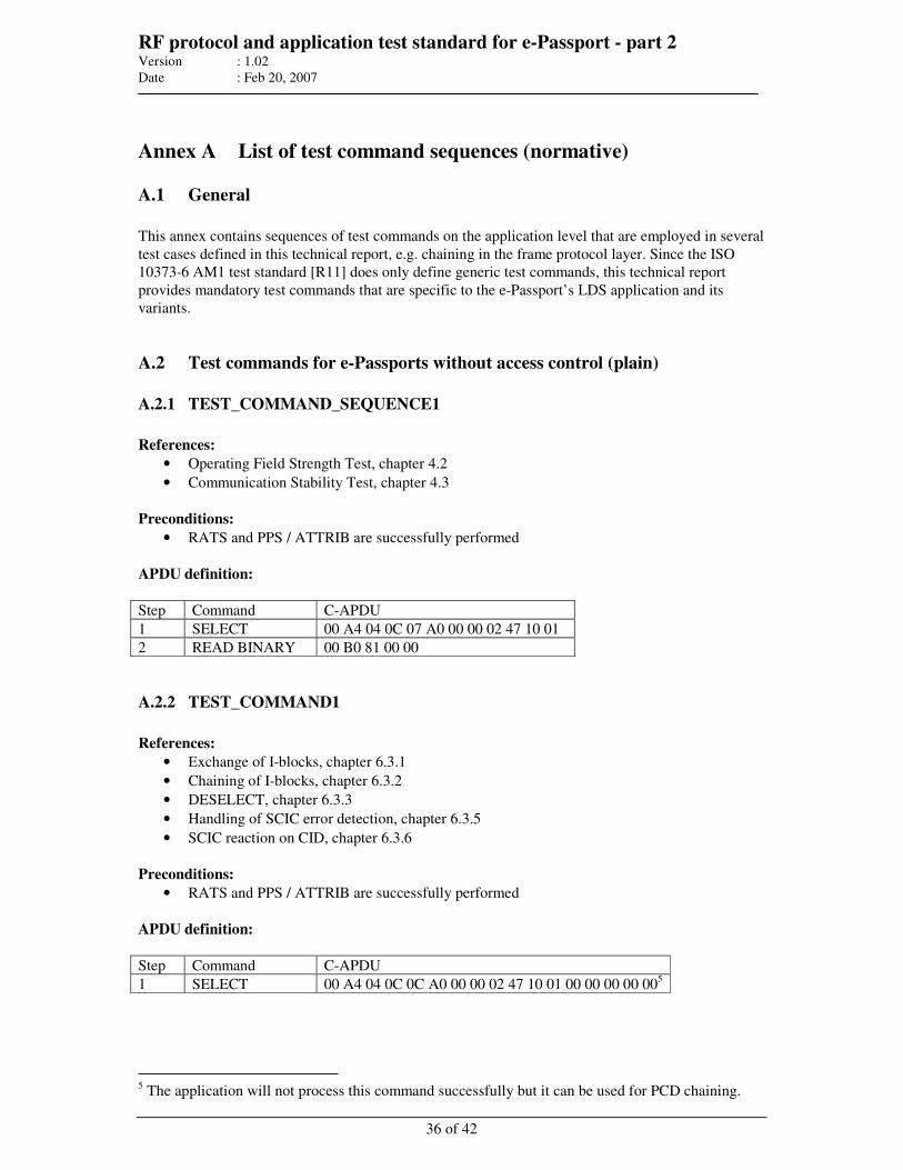
RF protocol and application test standard for e-Passport - part 2 Version : 1.02
Date : Feb 20, 2007
36 of 42
Annex A List of test command sequences (normative)
A.1 General
This annex contains sequences of test commands on the application level that are employed in several
test cases defined in this technical report, e.g. chaining in the frame protocol layer. Since the ISO
10373-6 AM1 test standard [R11] does only define generic test commands, this technical report
provides mandatory test commands that are specific to the e-Passport’s LDS application and its
variants.
A.2 Test commands for e-Passports without access control (plain)
A.2.1 TEST_COMMAND_SEQUENCE1
References:
• Operating Field Strength Test, chapter 4.2
• Communication Stability Test, chapter 4.3
Preconditions:
• RATS and PPS / ATTRIB are successfully performed
APDU definition:
Step Command C-APDU
1 SELECT 00 A4 04 0C 07 A0 00 00 02 47 10 01
2 READ BINARY 00 B0 81 00 00
A.2.2 TEST_COMMAND1
References:
• Exchange of I-blocks, chapter 6.3.1
• Chaining of I-blocks, chapter 6.3.2
• DESELECT, chapter 6.3.3
• Handling of SCIC error detection, chapter 6.3.5
• SCIC reaction on CID, chapter 6.3.6
Preconditions:
• RATS and PPS / ATTRIB are successfully performed
APDU definition:
Step Command C-APDU
1 SELECT 00 A4 04 0C 0C A0 00 00 02 47 10 01 00 00 00 00 005
5 The application will not process this command successfully but it can be used for PCD chaining.
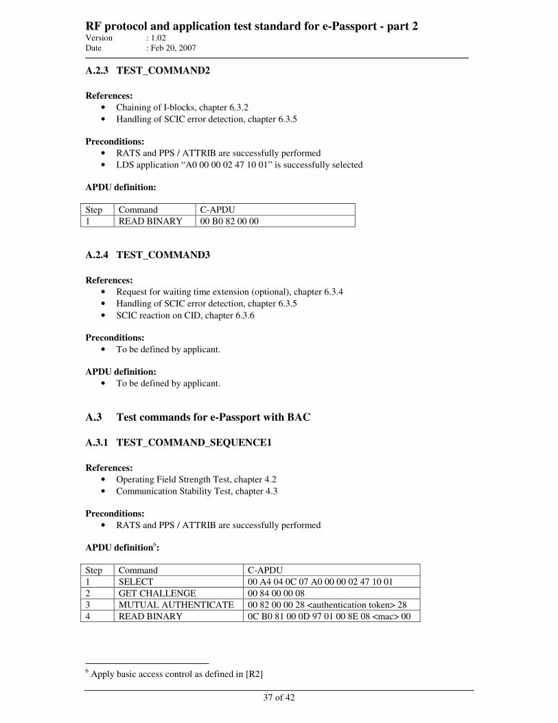
RF protocol and application test standard for e-Passport - part 2 Version : 1.02
Date : Feb 20, 2007
37 of 42
A.2.3 TEST_COMMAND2
References:
• Chaining of I-blocks, chapter 6.3.2
• Handling of SCIC error detection, chapter 6.3.5
Preconditions:
• RATS and PPS / ATTRIB are successfully performed
• LDS application “A0 00 00 02 47 10 01” is successfully selected
APDU definition:
Step Command C-APDU
1 READ BINARY 00 B0 82 00 00
A.2.4 TEST_COMMAND3
References:
• Request for waiting time extension (optional), chapter 6.3.4
• Handling of SCIC error detection, chapter 6.3.5
• SCIC reaction on CID, chapter 6.3.6
Preconditions:
• To be defined by applicant.
APDU definition:
• To be defined by applicant.
A.3 Test commands for e-Passport with BAC
A.3.1 TEST_COMMAND_SEQUENCE1
References:
• Operating Field Strength Test, chapter 4.2
• Communication Stability Test, chapter 4.3
Preconditions:
• RATS and PPS / ATTRIB are successfully performed
APDU definition6:
Step Command C-APDU
1 SELECT 00 A4 04 0C 07 A0 00 00 02 47 10 01
2 GET CHALLENGE 00 84 00 00 08
3 MUTUAL AUTHENTICATE 00 82 00 00 28 <authentication token> 28
4 READ BINARY 0C B0 81 00 0D 97 01 00 8E 08 <mac> 00
6 Apply basic access control as defined in [R2]
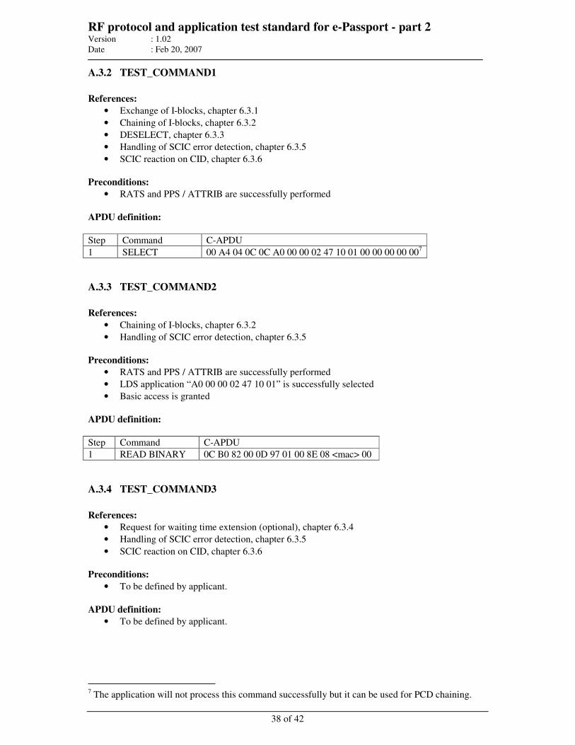
RF protocol and application test standard for e-Passport - part 2 Version : 1.02
Date : Feb 20, 2007
38 of 42
A.3.2 TEST_COMMAND1
References:
• Exchange of I-blocks, chapter 6.3.1
• Chaining of I-blocks, chapter 6.3.2
• DESELECT, chapter 6.3.3
• Handling of SCIC error detection, chapter 6.3.5
• SCIC reaction on CID, chapter 6.3.6
Preconditions:
• RATS and PPS / ATTRIB are successfully performed
APDU definition:
Step Command C-APDU
1 SELECT 00 A4 04 0C 0C A0 00 00 02 47 10 01 00 00 00 00 007
A.3.3 TEST_COMMAND2
References:
• Chaining of I-blocks, chapter 6.3.2
• Handling of SCIC error detection, chapter 6.3.5
Preconditions:
• RATS and PPS / ATTRIB are successfully performed
• LDS application “A0 00 00 02 47 10 01” is successfully selected
• Basic access is granted
APDU definition:
Step Command C-APDU
1 READ BINARY 0C B0 82 00 0D 97 01 00 8E 08 <mac> 00
A.3.4 TEST_COMMAND3
References:
• Request for waiting time extension (optional), chapter 6.3.4
• Handling of SCIC error detection, chapter 6.3.5
• SCIC reaction on CID, chapter 6.3.6
Preconditions:
• To be defined by applicant.
APDU definition:
• To be defined by applicant.
7 The application will not process this command successfully but it can be used for PCD chaining.
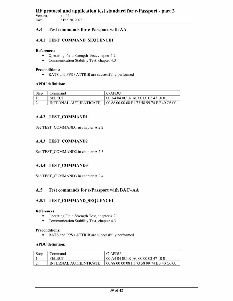
RF protocol and application test standard for e-Passport - part 2 Version : 1.02
Date : Feb 20, 2007
39 of 42
A.4 Test commands for e-Passport with AA
A.4.1 TEST_COMMAND_SEQUENCE1
References:
• Operating Field Strength Test, chapter 4.2
• Communication Stability Test, chapter 4.3
Preconditions:
• RATS and PPS / ATTRIB are successfully performed
APDU definition:
Step Command C-APDU
1 SELECT 00 A4 04 0C 07 A0 00 00 02 47 10 01
2 INTERNAL AUTHENTICATE 00 88 00 00 08 F1 73 58 99 74 BF 40 C6 00
A.4.2 TEST_COMMAND1
See TEST_COMMAND1 in chapter A.2.2
A.4.3 TEST_COMMAND2
See TEST_COMMAND2 in chapter A.2.3
A.4.4 TEST_COMMAND3
See TEST_COMMAND3 in chapter A.2.4
A.5 Test commands for e-Passport with BAC+AA
A.5.1 TEST_COMMAND_SEQUENCE1
References:
• Operating Field Strength Test, chapter 4.2
• Communication Stability Test, chapter 4.3
Preconditions:
• RATS and PPS / ATTRIB are successfully performed
APDU definition:
Step Command C-APDU
1 SELECT 00 A4 04 0C 07 A0 00 00 02 47 10 01
2 INTERNAL AUTHENTICATE 00 88 00 00 08 F1 73 58 99 74 BF 40 C6 00

RF protocol and application test standard for e-Passport - part 2 Version : 1.02
Date : Feb 20, 2007
40 of 42
A.5.2 TEST_COMMAND1
References:
• Exchange of I-blocks, chapter 6.3.1
• Chaining of I-blocks, chapter 6.3.2
• DESELECT, chapter 6.3.3
• Handling of SCIC error detection, chapter 6.3.5
• SCIC reaction on CID, chapter 6.3.6
Preconditions:
• RATS and PPS / ATTRIB are successfully performed
APDU definition:
Step Command C-APDU
1 SELECT 00 A4 04 0C 0C A0 00 00 02 47 10 01 00 00 00 00 008
A.5.3 TEST_COMMAND2
References:
• Chaining of I-blocks, chapter 6.3.2
• Handling of SCIC error detection, chapter 6.3.5
Preconditions:
• RATS and PPS / ATTRIB are successfully performed
• LDS application “A0 00 00 02 47 10 01” is successfully selected
• Basic access is granted
APDU definition:
Step Command C-APDU
1 READ BINARY 0C B0 82 00 0D 97 01 00 8E 08 <mac> 00
A.5.4 TEST_COMMAND3
References:
• Request for waiting time extension (optional), chapter 6.3.4
• Handling of SCIC error detection, chapter 6.3.5
• SCIC reaction on CID, chapter 6.3.6
Preconditions:
• To be defined by applicant.
APDU definition:
• To be defined by applicant.
8 The application will not process this command successfully but it can be used for PCD chaining.
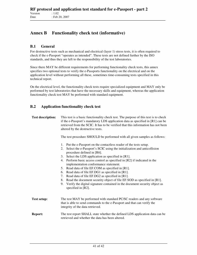
RF protocol and application test standard for e-Passport - part 2 Version : 1.02
Date : Feb 20, 2007
41 of 42
Annex B Functionality check test (informative)
B.1 General
For destructive tests such as mechanical and electrical (layer 1) stress tests, it is often required to
check if the e-Passport “operates as intended”. These tests are not defined further by the ISO
standards, and thus they are left to the responsibility of the test laboratories.
Since there MAY be different requirements for performing functionality check tests, this annex
specifies two optional tests to verify the e-Passports functionality on the electrical and on the
application level without performing all these, sometimes time-consuming tests specified in this
technical report.
On the electrical level, the functionality check tests require specialized equipment and MAY only be
performed by test laboratories that have the necessary skills and equipment, whereas the application
functionality check test MAY be performed with standard equipment.
B.2 Application functionality check test
Test description: This test is a basic functionality check test. The purpose of this test is to check
if the e-Passport’s mandatory LDS application data as specified in [R1] can be
retrieved from the SCIC. It has to be verified that this information has not been
altered by the destructive tests.
The test procedure SHOULD be performed with all given samples as follows:
1. Put the e-Passport on the contactless reader of the tests setup.
2. Select the e-Passport’s SCIC using the initialization and anticollision
procedure defined in [R6].
3. Select the LDS application as specified in [R1].
4. Perform basic access control as specified in [R2] if indicated in the
implementation conformance statement.
5. Read data of file EF.COM as specified in [R1].
6. Read data of file EF.DG1 as specified in [R1].
7. Read data of file EF.DG2 as specified in [R1].
8. Read the document security object of file EF.SOD as specified in [R1].
9. Verify the digital signature contained in the document security object as
specified in [R2].
Test setup: The test MAY be performed with standard PC/SC readers and any software
that is able to send commands to the e-Passport and that can verify the
integrity of the data retrieved.
Report: The test report SHALL state whether the defined LDS application data can be
retrieved and whether the data has been altered.
RF protocol and application test standard for e-Passport - part 2 Version : 1.02
Date : Feb 20, 2007
42 of 42
B.3 Electrical functionality check test
Test description: The purpose of this test is to check the electrical functionality of the e-Passport
and MAY be used in addition to the Application functionality check test
specified in chapter B.2.
The test procedure SHOULD be performed with all given samples using at lest
one of the following methods:
1. Apply the Resonance Frequency Test as specified in chapter 4.4.
2. Apply the Operating Field Strength Test as specified in chapter 4.2.
3. Apply an alternative method comparing relative values of the threshold
field strength before and after the mechanical or electrical stress test.
Test setup: For this test, the test setup defined in the corresponding chapters SHALL be
used.
Report: The test report SHALL state whether the resonance frequency is in the range
specified in the implementation conformance statement or whether the e-
Passport operates as intended for all combinations of temperatures and field
strengths, see chapter 4.2.
File : RF protocol Part 3 V1.01.doc
Author : ISO/JTC1/SC17/WG3/TF4 for ICAO-NTWG
MACHINE READABLE
TRAVEL DOCUMENTS
TECHNICAL REPORT
RF PROTOCOL AND APPLICATION TEST STANDARD
FOR E-PASSPORT - PART 3
TESTS FOR APPLICATION PROTOCOL AND LOGICAL
DATA STRUCTURE
Version: 1.01
Date – Feb 20, 2007
Published by authority of the Secretary General
INTERNATIONAL CIVIL AVIATION ORGANIZATION
APPENDIX C
RF protocol and application test standard for e-Passport - part 3 Version : 1.01
Date : Feb 20, 2007
2 of 80
Release Control
Release Date Description
0.1 23-11-2005 First draft based on the German WG3 TF4 contribution “e-Passport Conformity
Testing” version 1.02 presented at TF4 meeting in Paris Nov 21-23, 2005
0.2 21-12-2005 Updated version with new ICAO TR layout.
0.9 17-03-2006 Changes according to resolved comments from the WG3 TF4 meeting in Ottawa,
Jan 30 – Feb 02, 2006. The following major changes have been introduced:
• Less restrictive verification of status words
• Introduction of profiles to be tested
0.95 2006-08-31 Intermediate draft, updated version with resolved comments from the Graz meeting
Jun 12-13, 2006 and editorial changes. Some comments from Graz still unresolved.
Test suites D and E have been modified as follows: There will be one test suite to
check the protected command and one to check the unprotected commend.
Test suites D and E will no longer check the correctness of the SM implementation
since this is handled in test suite C
New test suites F and G for testing unprotected SelectFile and ReadBinary. Test
suites D and E will check the protected SelectFile and ReadBinary commands
respectively.
Redefined test cases (proposal) for test unit LDS_B – tests for DG1 – MRZ
Redefined test cases E_1 – E_3 and E_5 – E_22 because of unspecified EOF
reading.
0.96 2006-11-29 Final internal draft version including all resolved comments from the Bled meeting,
Oct 25-26, 2006.
Editorial changes in test suites C_9 and C_11 to clarify the encoding of offsets with
tag 54.
Editorial changes in test suites B and C. Former tests C_20 to C_36 have been
moved to test suite B because these tests cover security condition tests.
1.0 2006-12-18 Editorial changes in 7816_C_8, C_9, and C_11 (sequence of steps to be performed)
and in LDS_D_4 (reference changed to DOC9303, Annex A3.2)
1.01 2007-02-20 Test case 7816_C_16: verification of Postconditions removed
Release Note:
Release 2007-02-20 is the official version of the technical report by SC17 WG3
TF4 endorsed by ICAO-NTWG at the Portugal meeting. It replaces version
V1.0.
RF protocol and application test standard for e-Passport - part 3 Version : 1.01
Date : Feb 20, 2007
3 of 80
Table of contents
1 INTRODUCTION......................................................................................................................................... 7
1.1 SCOPE AND PURPOSE............................................................................................................................... 7 1.2 ASSUMPTIONS ......................................................................................................................................... 7 1.3 TERMINOLOGY ........................................................................................................................................ 7 1.4 GLOSSARY .............................................................................................................................................. 8 1.5 ABBREVIATIONS...................................................................................................................................... 8 1.6 REFERENCE DOCUMENTATION ................................................................................................................ 9
2 GENERAL TEST REQUIREMENTS ...................................................................................................... 10
2.1 TEST SETUP ........................................................................................................................................... 10 2.2 IMPLEMENTATION CONFORMANCE STATEMENT .................................................................................... 10 2.3 VERIFICATION OF ISO 7816-4 STATUS BYTES ....................................................................................... 11
3 SECURITY AND COMMAND TESTS.................................................................................................... 13
3.1 UNIT TEST ISO_7816_A – SELECTAPPLICATION COMMAND................................................................ 13 3.1.1 Test Case 7816_A_1 ........................................................................................................................ 13 3.1.2 Test Case 7816_A_2 ........................................................................................................................ 13
3.2 UNIT TEST ISO_7816_B – SECURITY CONDITIONS OF BAC PROTECTED E-PASSPORTS......................... 14 3.2.1 Test Case 7816_B_1 ........................................................................................................................ 14 3.2.2 Test Case 7816_B_2 ........................................................................................................................ 14 3.2.3 Test Case 7816_B_3 ........................................................................................................................ 15 3.2.4 Test Case 7816_B_4 ........................................................................................................................ 15 3.2.5 Test Case 7816_B_5 ........................................................................................................................ 15 3.2.6 Test Case 7816_B_6 ........................................................................................................................ 15 3.2.7 Test Case 7816_B_7 ........................................................................................................................ 16 3.2.8 Test Case 7816_B_8 ........................................................................................................................ 16 3.2.9 Test Case 7816_B_9 ........................................................................................................................ 16 3.2.10 Test Case 7816_B_10.................................................................................................................. 16 3.2.11 Test Case 7816_B_11.................................................................................................................. 17 3.2.12 Test Case 7816_B_12.................................................................................................................. 17 3.2.13 Test Case 7816_B_13.................................................................................................................. 17 3.2.14 Test Case 7816_B_14.................................................................................................................. 17 3.2.15 Test Case 7816_B_15.................................................................................................................. 18 3.2.16 Test Case 7816_B_16.................................................................................................................. 18 3.2.17 Test Case 7816_B_17.................................................................................................................. 18 3.2.18 Test Case 7816_B_18.................................................................................................................. 18 3.2.19 Test Case 7816_B_19.................................................................................................................. 19 3.2.20 Test Case 7816_B_20.................................................................................................................. 19 3.2.21 Test Case 7816_B_21.................................................................................................................. 19 3.2.22 Test Case 7816_B_22.................................................................................................................. 19 3.2.23 Test Case 7816_B_23.................................................................................................................. 20 3.2.24 Test Case 7816_B_24.................................................................................................................. 20 3.2.25 Test Case 7816_B_25.................................................................................................................. 20 3.2.26 Test Case 7816_B_26.................................................................................................................. 20 3.2.27 Test Case 7816_B_27.................................................................................................................. 21 3.2.28 Test Case 7816_B_28.................................................................................................................. 21 3.2.29 Test Case 7816_B_29.................................................................................................................. 21 3.2.30 Test Case 7816_B_30.................................................................................................................. 22 3.2.31 Test Case 7816_B_31.................................................................................................................. 22 3.2.32 Test Case 7816_B_32.................................................................................................................. 22 3.2.33 Test Case 7816_B_33.................................................................................................................. 22 3.2.34 Test Case 7816_B_34.................................................................................................................. 23 3.2.35 Test Case 7816_B_35.................................................................................................................. 23 3.2.36 Test Case 7816_B_36.................................................................................................................. 23 3.2.37 Test Case 7816_B_37.................................................................................................................. 23 3.2.38 Test Case 7816_B_38.................................................................................................................. 24 3.2.39 Test Case 7816_B_39.................................................................................................................. 24 3.2.40 Test Case 7816_B_40.................................................................................................................. 24
RF protocol and application test standard for e-Passport - part 3 Version : 1.01
Date : Feb 20, 2007
4 of 80
3.2.41 Test Case 7816_B_41.................................................................................................................. 25 3.2.42 Test Case 7816_B_42.................................................................................................................. 25 3.2.43 Test Case 7816_B_43.................................................................................................................. 26 3.2.44 Test Case 7816_B_44.................................................................................................................. 26 3.2.45 Test Case 7816_B_45.................................................................................................................. 26 3.2.46 Test Case 7816_B_46.................................................................................................................. 27 3.2.47 Test Case 7816_B_47.................................................................................................................. 27 3.2.48 Test Case 7816_B_48.................................................................................................................. 27 3.2.49 Test Case 7816_B_49.................................................................................................................. 28 3.2.50 Test Case 7816_B_50.................................................................................................................. 28 3.2.51 Test Case 7816_B_51.................................................................................................................. 28 3.2.52 Test Case 7816_B_52.................................................................................................................. 29 3.2.53 Test Case 7816_B_53.................................................................................................................. 29 3.2.54 Test Case 7816_B_54.................................................................................................................. 29
3.3 UNIT TEST ISO_7816_C – BASIC ACCESS CONTROL............................................................................ 30 3.3.1 Test Case 7816_C_1 ........................................................................................................................ 30 3.3.2 Test Case 7816_C_2 ........................................................................................................................ 30 3.3.3 Test Case 7816_C_3 ........................................................................................................................ 31 3.3.4 Test Case 7816_C_4 ........................................................................................................................ 31 3.3.5 Test Case 7816_C_5 ........................................................................................................................ 32 3.3.6 Test Case 7816_C_6 ........................................................................................................................ 32 3.3.7 Test Case 7816_C_7 ........................................................................................................................ 33 3.3.8 Test Case 7816_C_8 ........................................................................................................................ 33 3.3.9 Test Case 7816_C_9 ........................................................................................................................ 33 3.3.10 Test Case 7816_C_10.................................................................................................................. 34 3.3.11 Test Case 7816_C_11.................................................................................................................. 35 3.3.12 Test Case 7816_C_12.................................................................................................................. 36 3.3.13 Test Case 7816_C_13.................................................................................................................. 36 3.3.14 Test Case 7816_C_14.................................................................................................................. 37 3.3.15 Test Case 7816_C_15.................................................................................................................. 37 3.3.16 Test Case 7816_C_16.................................................................................................................. 37 3.3.17 Test Case 7816_C_17.................................................................................................................. 38 3.3.18 Test Case 7816_C_18.................................................................................................................. 38 3.3.19 Test Case 7816_C_19.................................................................................................................. 38
3.4 UNIT TEST ISO_7816_D – PROTECTED SELECTFILE COMMAND .......................................................... 39 3.4.1 Test Case 7816_D_1........................................................................................................................ 39 3.4.2 Test Case 7816_D_2........................................................................................................................ 39 3.4.3 Test Case 7816_D_3........................................................................................................................ 40 3.4.4 Test Case 7816_D_4........................................................................................................................ 40 3.4.5 Test Case 7816_D_5........................................................................................................................ 40 3.4.6 Test Case 7816_D_6........................................................................................................................ 41 3.4.7 Test Case 7816_D_7........................................................................................................................ 41 3.4.8 Test Case 7816_D_8........................................................................................................................ 41 3.4.9 Test Case 7816_D_9........................................................................................................................ 42 3.4.10 Test Case 7816_D_10 ................................................................................................................. 42 3.4.11 Test Case 7816_D_11 ................................................................................................................. 42 3.4.12 Test Case 7816_D_12 ................................................................................................................. 43 3.4.13 Test Case 7816_D_13 ................................................................................................................. 43 3.4.14 Test Case 7816_D_14 ................................................................................................................. 43 3.4.15 Test Case 7816_D_15 ................................................................................................................. 44 3.4.16 Test Case 7816_D_16 ................................................................................................................. 44 3.4.17 Test Case 7816_D_17 ................................................................................................................. 44 3.4.18 Test Case 7816_D_18 ................................................................................................................. 45 3.4.19 Test Case 7816_D_19 ................................................................................................................. 45 3.4.20 Test Case 7816_D_20 ................................................................................................................. 45 3.4.21 Test Case 7816_D_21 ................................................................................................................. 46 3.4.22 Test Case 7816_D_22 ................................................................................................................. 46 3.4.23 Test Case 7816_D_23 ................................................................................................................. 46
3.5 UNIT TEST ISO_7816_E – PROTECTED READBINARY COMMAND........................................................ 47 3.5.1 Test Case 7816_E_1 ........................................................................................................................ 47
RF protocol and application test standard for e-Passport - part 3 Version : 1.01
Date : Feb 20, 2007
5 of 80
3.5.2 Test Case 7816_E_2 ........................................................................................................................ 47 3.5.3 Test Case 7816_E_3 ........................................................................................................................ 48 3.5.4 Test Case 7816_E_4 ........................................................................................................................ 48 3.5.5 Test Case 7816_E_5 ........................................................................................................................ 48 3.5.6 Test Case 7816_E_6 ........................................................................................................................ 49 3.5.7 Test Case 7816_E_7 ........................................................................................................................ 49 3.5.8 Test Case 7816_E_8 ........................................................................................................................ 49 3.5.9 Test Case 7816_E_9 ........................................................................................................................ 49 3.5.10 Test Case 7816_E_10.................................................................................................................. 50 3.5.11 Test Case 7816_E_11.................................................................................................................. 50 3.5.12 Test Case 7816_E_12.................................................................................................................. 50 3.5.13 Test Case 7816_E_13.................................................................................................................. 50 3.5.14 Test Case 7816_E_14.................................................................................................................. 51 3.5.15 Test Case 7816_E_15.................................................................................................................. 51 3.5.16 Test Case 7816_E_16.................................................................................................................. 51 3.5.17 Test Case 7816_E_17.................................................................................................................. 51 3.5.18 Test Case 7816_E_18.................................................................................................................. 52 3.5.19 Test Case 7816_E_19.................................................................................................................. 52 3.5.20 Test Case 7816_E_20.................................................................................................................. 52 3.5.21 Test Case 7816_E_21.................................................................................................................. 52 3.5.22 Test Case 7816_E_22.................................................................................................................. 53
3.6 UNIT TEST ISO_7816_F – UNPROTECTED SELECTFILE COMMAND ...................................................... 53 3.6.1 Test Case 7816_F_1 ........................................................................................................................ 53 3.6.2 Test Case 7816_F_2 ........................................................................................................................ 53 3.6.3 Test Case 7816_F_3 ........................................................................................................................ 54 3.6.4 Test Case 7816_F_4 ........................................................................................................................ 54 3.6.5 Test Case 7816_F_5 ........................................................................................................................ 54 3.6.6 Test Case 7816_F_6 ........................................................................................................................ 55 3.6.7 Test Case 7816_F_7 ........................................................................................................................ 55 3.6.8 Test Case 7816_F_8 ........................................................................................................................ 55 3.6.9 Test Case 7816_F_9 ........................................................................................................................ 56 3.6.10 Test Case 7816_F_10.................................................................................................................. 56 3.6.11 Test Case 7816_F_11.................................................................................................................. 56 3.6.12 Test Case 7816_F_12.................................................................................................................. 57 3.6.13 Test Case 7816_F_13.................................................................................................................. 57 3.6.14 Test Case 7816_F_14.................................................................................................................. 57 3.6.15 Test Case 7816_F_15.................................................................................................................. 58 3.6.16 Test Case 7816_F_16.................................................................................................................. 58 3.6.17 Test Case 7816_F_17.................................................................................................................. 58 3.6.18 Test Case 7816_F_18.................................................................................................................. 59 3.6.19 Test Case 7816_F_19.................................................................................................................. 59 3.6.20 Test Case 7816_F_20.................................................................................................................. 59 3.6.21 Test Case 7816_F_21.................................................................................................................. 60 3.6.22 Test Case 7816_F_22.................................................................................................................. 60 3.6.23 Test Case 7816_F_23.................................................................................................................. 60
3.7 UNIT TEST ISO_7816_G – UNPROTECTED READBINARY COMMAND................................................... 61 3.7.1 Test Case 7816_G_1........................................................................................................................ 61 3.7.2 Test Case 7816_G_2........................................................................................................................ 61 3.7.3 Test Case 7816_G_3........................................................................................................................ 61 3.7.4 Test Case 7816_G_4........................................................................................................................ 62 3.7.5 Test Case 7816_G_5........................................................................................................................ 62 3.7.6 Test Case 7816_G_6........................................................................................................................ 62 3.7.7 Test Case 7816_G_7........................................................................................................................ 63 3.7.8 Test Case 7816_G_8........................................................................................................................ 63 3.7.9 Test Case 7816_G_9........................................................................................................................ 63 3.7.10 Test Case 7816_G_10 ................................................................................................................. 63 3.7.11 Test Case 7816_G_11 ................................................................................................................. 64 3.7.12 Test Case 7816_G_12 ................................................................................................................. 64 3.7.13 Test Case 7816_G_13 ................................................................................................................. 64 3.7.14 Test Case 7816_G_14 ................................................................................................................. 64
RF protocol and application test standard for e-Passport - part 3 Version : 1.01
Date : Feb 20, 2007
6 of 80
3.7.15 Test Case 7816_G_15 ................................................................................................................. 65 3.7.16 Test Case 7816_G_16 ................................................................................................................. 65 3.7.17 Test Case 7816_G_17 ................................................................................................................. 65 3.7.18 Test Case 7816_G_18 ................................................................................................................. 65 3.7.19 Test Case 7816_G_19 ................................................................................................................. 66 3.7.20 Test Case 7816_G_20 ................................................................................................................. 66 3.7.21 Test Case 7816_G_21 ................................................................................................................. 66 3.7.22 Test Case 7816_G_22 ................................................................................................................. 66
4 LOGICAL DATA STRUCTURE TESTS................................................................................................. 67
4.1 UNIT TEST LDS_A - TESTS FOR THE EF.COM LDS OBJECT ................................................................ 67 4.1.1 Test Case LDS_A_01 ....................................................................................................................... 67 4.1.2 Test Case LDS_A_02 ....................................................................................................................... 67 4.1.3 Test Case LDS_A_03 ....................................................................................................................... 67 4.1.4 Test Case LDS_A_04 ....................................................................................................................... 68 4.1.5 Test Case LDS_A_05 ....................................................................................................................... 68
4.2 UNIT TEST LDS_B - TESTS FOR THE DATAGROUP 1 LDS OBJECT ........................................................ 69 4.2.1 Test Case LDS_B_01 ....................................................................................................................... 69 4.2.2 Test Case LDS_B_02 ....................................................................................................................... 69 4.2.3 Test Case LDS_B_03 ....................................................................................................................... 69 4.2.4 Test Case LDS_B_04 ....................................................................................................................... 70 4.2.5 Test Case LDS_B_05 ....................................................................................................................... 70 4.2.6 Test Case LDS_B_06 ....................................................................................................................... 70 4.2.7 Test Case LDS_B_07 ....................................................................................................................... 70 4.2.8 Test Case LDS_B_08 ....................................................................................................................... 71 4.2.9 Test Case LDS_B_09 ....................................................................................................................... 71 4.2.10 Test Case LDS_B_10................................................................................................................... 71 4.2.11 Test Case LDS_B_11................................................................................................................... 71 4.2.12 Test Case LDS_B_12................................................................................................................... 72 4.2.13 Test Case LDS_B_13................................................................................................................... 72
4.3 UNIT TEST LDS_C - TESTS FOR THE DATAGROUP 2 LDS OBJECT ........................................................ 72 4.3.1 Test Case LDS_C_01 ....................................................................................................................... 72 4.3.2 Test Case LDS_C_02 ....................................................................................................................... 73 4.3.3 Test Case LDS_C_03 ....................................................................................................................... 73 4.3.4 Test Case LDS_C_04 ....................................................................................................................... 73 4.3.5 Test Case LDS_C_05 ....................................................................................................................... 74 4.3.6 Test Case LDS_C_06 ....................................................................................................................... 74 4.3.7 Test Case LDS_C_07 ....................................................................................................................... 74 4.3.8 Test Case LDS_C_08 ....................................................................................................................... 75 4.3.9 Test Case LDS_C_09 ....................................................................................................................... 75 4.3.10 Test Case LDS_C_10................................................................................................................... 75 4.3.11 Test Case LDS_C_11................................................................................................................... 76 4.3.12 Test Case LDS_C_12................................................................................................................... 76 4.3.13 Test Case LDS_C_13................................................................................................................... 77
4.4 UNIT TEST LDS_D - TESTS FOR THE SOD LDS OBJECT ....................................................................... 77 4.4.1 Test Case LDS_D_01....................................................................................................................... 77 4.4.2 Test Case LDS_D_02....................................................................................................................... 77 4.4.3 Test Case LDS_D_03....................................................................................................................... 78 4.4.4 Test Case LDS_D_04....................................................................................................................... 78 4.4.5 Test Case LDS_D_05....................................................................................................................... 78 4.4.6 Test Case LDS_D_06....................................................................................................................... 79 4.4.7 Test Case LDS_D_07....................................................................................................................... 80
RF protocol and application test standard for e-Passport - part 3 Version : 1.01
Date : Feb 20, 2007
7 of 80
1 Introduction
1.1 Scope and purpose
An essential element of the new ICAO compliant e-Passport is the addition of a Secure Contactless
Integrated Circuit (SCIC) that holds securely biometric data of the e-Passport bearer within the ICAO
defined Logical Data Structure (LDS).
Successful integration of the SCIC into the e-Passport depends upon active international cooperation
between many companies and organizations.
The e-Passport has been specified and designed to operate correctly across a wide variety of reading
infrastructures worldwide. The risk profile for the e-Passport indicates a high impact if that design
includes a widespread error or fault. Therefore it is essential, that all companies and organizations
involved make all reasonable efforts to minimize the probability that this error or fault remains
undetected before that design is approved and e-Passports are issued.
This test specification covers the application interface, i.e. the ISO7816 conformance of the e-
Passport Chip and the conformance of the LDS.
The ISO7816 conformance tests are restricted to the commands defined in the LDS 1.7 [R1] and PKI
1.1 [R2] specifications. Other commands especially file creation and personalization commands are
beyond the scope of this document.
The logical data structure test layer analyses the encoding of the LDS objects stored on an e-Passport.
This layer contains several test units, one for each LDS object (DG 1 - 16, EF.COM and EF.SOD).
Another test unit verifies the integrity and consistency of the different data structures. The tests
specified for this layer can be performed using a regular e-Passport or with given input data from a
different source (e.g. file). The test configuration document specifies the source of the data.
1.2 Assumptions
It is assumed that the electrical interface and the underlying transport protocol are functionally tested.
Thus, failures introduced by the RF protocol are out of scope of the test cases defined here.
1.3 Terminology
The key words "MUST", "SHALL", "REQUIRED", "SHOULD", "RECOMMENDED", and "MAY"
in this document are to be interpreted as described in [R3].
MUST This word, or the terms "REQUIRED" or "SHALL", mean that the definition is an
absolute requirement of the specification.
MUST NOT This phrase, or the phrase "SHALL NOT", mean that the definition is an absolute
prohibition of the specification.
SHOULD This word, or the adjective "RECOMMENDED", mean that there may exist valid
reasons in particular circumstances to ignore a particular item, but the full
implications must be understood and carefully weighed before choosing a different
course.
SHOULD NOT This phrase, or the phrase "NOT RECOMMENDED" mean that there may exist
valid reasons in particular circumstances when the particular behavior is acceptable
or even useful, but the full implications should be understood and the case carefully
weighed before implementing any behavior described with this label.
RF protocol and application test standard for e-Passport - part 3 Version : 1.01
Date : Feb 20, 2007
8 of 80
MAY This word, or the adjective "OPTIONAL", mean that an item is truly optional. One
vendor may choose to include the item because a particular marketplace requires it or
because the vendor feels that it enhances the product while another vendor may omit
the same item. An implementation which does not include a particular option MUST
be prepared to interoperate with another implementation which does include the
option, though perhaps with reduced functionality. In the same vein an
implementation which does include a particular option MUST be prepared to
interoperate with another implementation which does not include the option (except,
of course, for the feature the option provides.)
1.4 Glossary
Command data field The command data field defines the data of a command APDU that follows the
command header and the Lc field – except the Le field. Its length is defined by Lc.
Command header The command header comprises the first four bytes of the command APDU sent to
the e-Passport in compliance with ISO 7816-4 [R6]. The header consists of the bytes
CLA, INS, P1, and P2.
Lc Length field of the command APDU encoding the number of bytes in the command
data field. In this specification, Lc is encoded in one byte (short length).
Le Length field of the command APDU encoding the maximum number of bytes
expected in the response data field. In this specification, Le is encoded in one byte
(short length).
Response data Response data is the string of bytes that is encoded in the response data field.
Response data field The response data field defines the data – except the response trailer – that the e-
Passport returns in the response APDU in compliance with ISO 7816-4 [R6].
Response trailer The response trailer defines the last two bytes that the e-Passport returns in the
response APDU. The response trailer consists of two status bytes in compliance with
ISO 7816-4 [R6].
Status bytes The status bytes SW1-SW2 indicate the processing state of the LDS application in
compliance with ISO 7816-4 [R6].
‘80’, ‘AB CD’ Bytes or byte strings encoded in Hex-ASCII will be denoted in apostrophes.
1.5 Abbreviations
Abbreviation
AA Active authentication
AID Application identifier
APDU Application protocol data unit
BAC Basic access control
CLA Class byte
DF Dedicated file
DG Data group
DO Data object
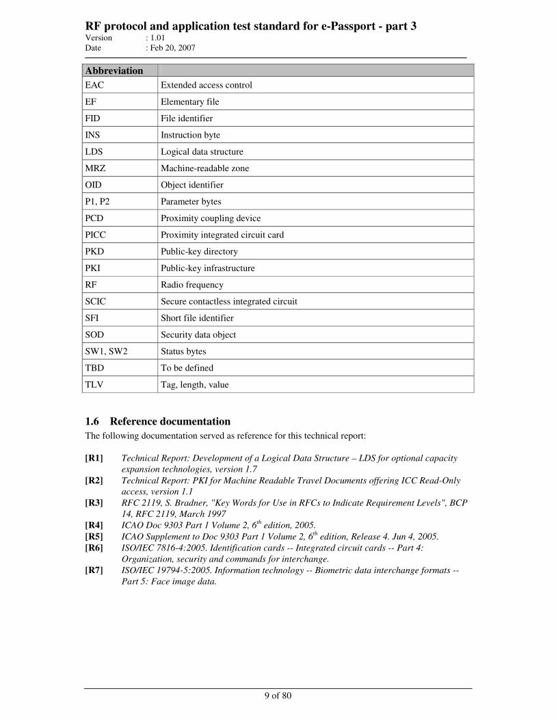
RF protocol and application test standard for e-Passport - part 3 Version : 1.01
Date : Feb 20, 2007
9 of 80
Abbreviation
EAC Extended access control
EF Elementary file
FID File identifier
INS Instruction byte
LDS Logical data structure
MRZ Machine-readable zone
OID Object identifier
P1, P2 Parameter bytes
PCD Proximity coupling device
PICC Proximity integrated circuit card
PKD Public-key directory
PKI Public-key infrastructure
RF Radio frequency
SCIC Secure contactless integrated circuit
SFI Short file identifier
SOD Security data object
SW1, SW2 Status bytes
TBD To be defined
TLV Tag, length, value
1.6 Reference documentation
The following documentation served as reference for this technical report:
[R1] Technical Report: Development of a Logical Data Structure – LDS for optional capacity
expansion technologies, version 1.7
[R2] Technical Report: PKI for Machine Readable Travel Documents offering ICC Read-Only
access, version 1.1
[R3] RFC 2119, S. Bradner, "Key Words for Use in RFCs to Indicate Requirement Levels", BCP
14, RFC 2119, March 1997
[R4] ICAO Doc 9303 Part 1 Volume 2, 6th edition, 2005.
[R5] ICAO Supplement to Doc 9303 Part 1 Volume 2, 6th edition, Release 4. Jun 4, 2005.
[R6] ISO/IEC 7816-4:2005. Identification cards -- Integrated circuit cards -- Part 4:
Organization, security and commands for interchange.
[R7] ISO/IEC 19794-5:2005. Information technology -- Biometric data interchange formats --
Part 5: Face image data.
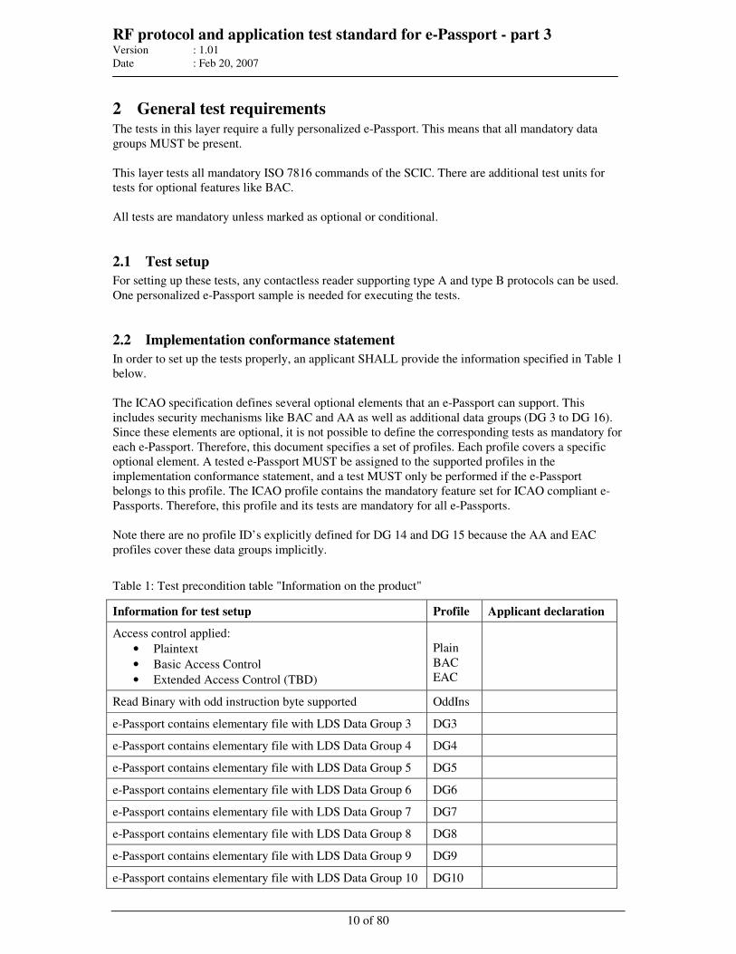
RF protocol and application test standard for e-Passport - part 3 Version : 1.01
Date : Feb 20, 2007
10 of 80
2 General test requirements The tests in this layer require a fully personalized e-Passport. This means that all mandatory data
groups MUST be present.
This layer tests all mandatory ISO 7816 commands of the SCIC. There are additional test units for
tests for optional features like BAC.
All tests are mandatory unless marked as optional or conditional.
2.1 Test setup
For setting up these tests, any contactless reader supporting type A and type B protocols can be used.
One personalized e-Passport sample is needed for executing the tests.
2.2 Implementation conformance statement
In order to set up the tests properly, an applicant SHALL provide the information specified in Table 1
below.
The ICAO specification defines several optional elements that an e-Passport can support. This
includes security mechanisms like BAC and AA as well as additional data groups (DG 3 to DG 16).
Since these elements are optional, it is not possible to define the corresponding tests as mandatory for
each e-Passport. Therefore, this document specifies a set of profiles. Each profile covers a specific
optional element. A tested e-Passport MUST be assigned to the supported profiles in the
implementation conformance statement, and a test MUST only be performed if the e-Passport
belongs to this profile. The ICAO profile contains the mandatory feature set for ICAO compliant e-
Passports. Therefore, this profile and its tests are mandatory for all e-Passports.
Note there are no profile ID’s explicitly defined for DG 14 and DG 15 because the AA and EAC
profiles cover these data groups implicitly.
Table 1: Test precondition table "Information on the product"
Information for test setup Profile Applicant declaration
Access control applied:
• Plaintext
• Basic Access Control
• Extended Access Control (TBD)
Plain
BAC
EAC
Read Binary with odd instruction byte supported OddIns
e-Passport contains elementary file with LDS Data Group 3 DG3
e-Passport contains elementary file with LDS Data Group 4 DG4
e-Passport contains elementary file with LDS Data Group 5 DG5
e-Passport contains elementary file with LDS Data Group 6 DG6
e-Passport contains elementary file with LDS Data Group 7 DG7
e-Passport contains elementary file with LDS Data Group 8 DG8
e-Passport contains elementary file with LDS Data Group 9 DG9
e-Passport contains elementary file with LDS Data Group 10 DG10
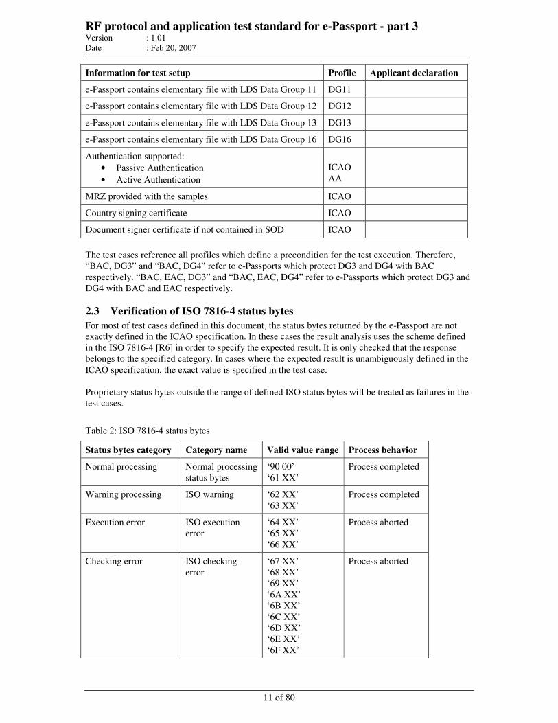
RF protocol and application test standard for e-Passport - part 3 Version : 1.01
Date : Feb 20, 2007
11 of 80
Information for test setup Profile Applicant declaration
e-Passport contains elementary file with LDS Data Group 11 DG11
e-Passport contains elementary file with LDS Data Group 12 DG12
e-Passport contains elementary file with LDS Data Group 13 DG13
e-Passport contains elementary file with LDS Data Group 16 DG16
Authentication supported:
• Passive Authentication
• Active Authentication
ICAO
AA
MRZ provided with the samples ICAO
Country signing certificate ICAO
Document signer certificate if not contained in SOD ICAO
The test cases reference all profiles which define a precondition for the test execution. Therefore,
“BAC, DG3” and “BAC, DG4” refer to e-Passports which protect DG3 and DG4 with BAC
respectively. “BAC, EAC, DG3” and “BAC, EAC, DG4” refer to e-Passports which protect DG3 and
DG4 with BAC and EAC respectively.
2.3 Verification of ISO 7816-4 status bytes
For most of test cases defined in this document, the status bytes returned by the e-Passport are not
exactly defined in the ICAO specification. In these cases the result analysis uses the scheme defined
in the ISO 7816-4 [R6] in order to specify the expected result. It is only checked that the response
belongs to the specified category. In cases where the expected result is unambiguously defined in the
ICAO specification, the exact value is specified in the test case.
Proprietary status bytes outside the range of defined ISO status bytes will be treated as failures in the
test cases.
Table 2: ISO 7816-4 status bytes
Status bytes category Category name Valid value range Process behavior
Normal processing Normal processing
status bytes
‘90 00’
‘61 XX’
Process completed
Warning processing ISO warning ‘62 XX’
‘63 XX’
Process completed
Execution error ISO execution
error
‘64 XX’
‘65 XX’
‘66 XX’
Process aborted
Checking error ISO checking
error
‘67 XX’
‘68 XX’
‘69 XX’
‘6A XX’
‘6B XX’
‘6C XX’
‘6D XX’
‘6E XX’
‘6F XX’
Process aborted

RF protocol and application test standard for e-Passport - part 3 Version : 1.01
Date : Feb 20, 2007
12 of 80
Note: There is a significant difference between normal and warning processing on the one side and
execution and checking error on the other side. The first group is returned if the process has been
fully completed, and the e-Passport MAY return some additional data. The “process aborted”
categories are issued if the command cannot be performed. Therefore, response data MUST NOT be
returned. In all test cases where an execution or checking error is expected, it MUST be verified that
the e-Passport does not return any response data except SM protocol elements (DO ‘99’ / ‘8E’).
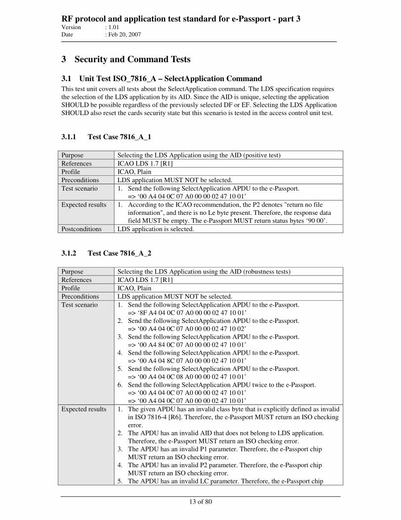
RF protocol and application test standard for e-Passport - part 3 Version : 1.01
Date : Feb 20, 2007
13 of 80
3 Security and Command Tests
3.1 Unit Test ISO_7816_A – SelectApplication Command
This test unit covers all tests about the SelectApplication command. The LDS specification requires
the selection of the LDS application by its AID. Since the AID is unique, selecting the application
SHOULD be possible regardless of the previously selected DF or EF. Selecting the LDS Application
SHOULD also reset the cards security state but this scenario is tested in the access control unit test.
3.1.1 Test Case 7816_A_1
Purpose Selecting the LDS Application using the AID (positive test)
References ICAO LDS 1.7 [R1]
Profile ICAO, Plain
Preconditions LDS application MUST NOT be selected.
Test scenario 1. Send the following SelectApplication APDU to the e-Passport.
=> ‘00 A4 04 0C 07 A0 00 00 02 47 10 01’
Expected results 1. According to the ICAO recommendation, the P2 denotes "return no file
information", and there is no Le byte present. Therefore, the response data
field MUST be empty. The e-Passport MUST return status bytes ‘90 00’.
Postconditions LDS application is selected.
3.1.2 Test Case 7816_A_2
Purpose Selecting the LDS Application using the AID (robustness tests)
References ICAO LDS 1.7 [R1]
Profile ICAO, Plain
Preconditions LDS application MUST NOT be selected.
Test scenario 1. Send the following SelectApplication APDU to the e-Passport.
=> ‘8F A4 04 0C 07 A0 00 00 02 47 10 01’
2. Send the following SelectApplication APDU to the e-Passport.
=> ‘00 A4 04 0C 07 A0 00 00 02 47 10 02’
3. Send the following SelectApplication APDU to the e-Passport.
=> ‘00 A4 84 0C 07 A0 00 00 02 47 10 01’
4. Send the following SelectApplication APDU to the e-Passport.
=> ‘00 A4 04 8C 07 A0 00 00 02 47 10 01’
5. Send the following SelectApplication APDU to the e-Passport.
=> ‘00 A4 04 0C 08 A0 00 00 02 47 10 01’
6. Send the following SelectApplication APDU twice to the e-Passport.
=> ‘00 A4 04 0C 07 A0 00 00 02 47 10 01’
=> ‘00 A4 04 0C 07 A0 00 00 02 47 10 01’
Expected results 1. The given APDU has an invalid class byte that is explicitly defined as invalid
in ISO 7816-4 [R6]. Therefore, the e-Passport MUST return an ISO checking
error.
2. The APDU has an invalid AID that does not belong to LDS application.
Therefore, the e-Passport MUST return an ISO checking error.
3. The APDU has an invalid P1 parameter. Therefore, the e-Passport chip
MUST return an ISO checking error.
4. The APDU has an invalid P2 parameter. Therefore, the e-Passport chip
MUST return an ISO checking error.
5. The APDU has an invalid LC parameter. Therefore, the e-Passport chip
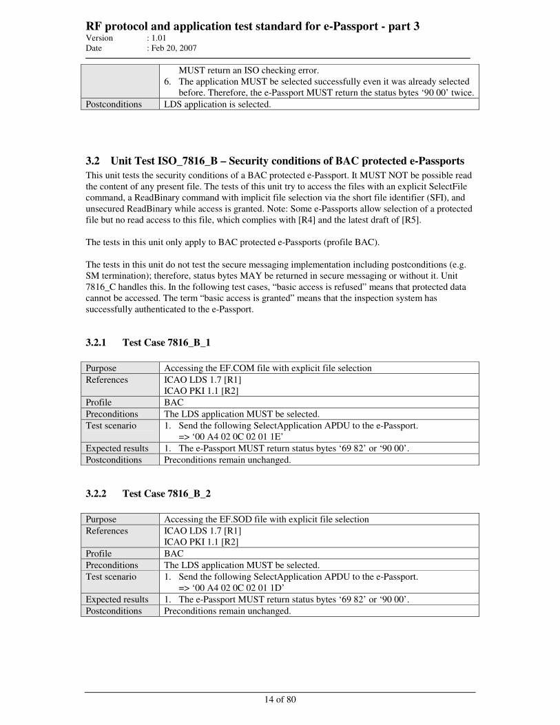
RF protocol and application test standard for e-Passport - part 3 Version : 1.01
Date : Feb 20, 2007
14 of 80
MUST return an ISO checking error.
6. The application MUST be selected successfully even it was already selected
before. Therefore, the e-Passport MUST return the status bytes ‘90 00’ twice.
Postconditions LDS application is selected.
3.2 Unit Test ISO_7816_B – Security conditions of BAC protected e-Passports
This unit tests the security conditions of a BAC protected e-Passport. It MUST NOT be possible read
the content of any present file. The tests of this unit try to access the files with an explicit SelectFile
command, a ReadBinary command with implicit file selection via the short file identifier (SFI), and
unsecured ReadBinary while access is granted. Note: Some e-Passports allow selection of a protected
file but no read access to this file, which complies with [R4] and the latest draft of [R5].
The tests in this unit only apply to BAC protected e-Passports (profile BAC).
The tests in this unit do not test the secure messaging implementation including postconditions (e.g.
SM termination); therefore, status bytes MAY be returned in secure messaging or without it. Unit
7816_C handles this. In the following test cases, “basic access is refused” means that protected data
cannot be accessed. The term “basic access is granted” means that the inspection system has
successfully authenticated to the e-Passport.
3.2.1 Test Case 7816_B_1
Purpose Accessing the EF.COM file with explicit file selection
References ICAO LDS 1.7 [R1]
ICAO PKI 1.1 [R2]
Profile BAC
Preconditions The LDS application MUST be selected.
Test scenario 1. Send the following SelectApplication APDU to the e-Passport.
=> ‘00 A4 02 0C 02 01 1E’
Expected results 1. The e-Passport MUST return status bytes ‘69 82’ or ‘90 00’.
Postconditions Preconditions remain unchanged.
3.2.2 Test Case 7816_B_2
Purpose Accessing the EF.SOD file with explicit file selection
References ICAO LDS 1.7 [R1]
ICAO PKI 1.1 [R2]
Profile BAC
Preconditions The LDS application MUST be selected.
Test scenario 1. Send the following SelectApplication APDU to the e-Passport.
=> ‘00 A4 02 0C 02 01 1D’
Expected results 1. The e-Passport MUST return status bytes ‘69 82’ or ‘90 00’.
Postconditions Preconditions remain unchanged.

RF protocol and application test standard for e-Passport - part 3 Version : 1.01
Date : Feb 20, 2007
15 of 80
3.2.3 Test Case 7816_B_3
Purpose Accessing the EF.DG1 file with explicit file selection
References ICAO LDS 1.7 [R1]
ICAO PKI 1.1 [R2]
Profile BAC
Preconditions The LDS application MUST be selected.
Test scenario 1. Send the following SelectApplication APDU to the e-Passport.
=> ‘00 A4 02 0C 02 01 01’
Expected results 1. The e-Passport MUST return status bytes ‘69 82’ or 90 00.
Postconditions Preconditions remain unchanged.
3.2.4 Test Case 7816_B_4
Purpose Accessing the EF.DG2 file with explicit file selection
References ICAO LDS 1.7 [R1]
ICAO PKI 1.1 [R2]
Profile BAC
Preconditions The LDS application MUST be selected.
Test scenario 1. Send the following SelectApplication APDU to the e-Passport.
=> ‘00 A4 02 0C 02 01 02’
Expected results 1. The e-Passport MUST return status bytes ‘69 82’ or ‘90 00’.
Postconditions Preconditions remain unchanged.
3.2.5 Test Case 7816_B_5
Purpose Accessing the EF.DG3 file with explicit file selection
References ICAO LDS 1.7 [R1]
ICAO PKI 1.1 [R2]
Profile BAC, EAC, DG3
Preconditions The LDS application MUST be selected.
Test scenario 1. Send the following SelectApplication APDU to the e-Passport.
=> ‘00 A4 02 0C 02 01 03’
Expected results 1. The e-Passport MUST return status bytes ‘69 82’ or ‘90 00’.
Postconditions Preconditions remain unchanged.
3.2.6 Test Case 7816_B_6
Purpose Accessing the EF.DG4 file with explicit file selection
References ICAO LDS 1.7 [R1]
ICAO PKI 1.1 [R2]
Profile BAC, EAC, DG4
Preconditions The LDS application MUST be selected.
Test scenario 1. Send the following SelectApplication APDU to the e-Passport.
=> ‘00 A4 02 0C 02 01 04’
Expected results 1. The e-Passport MUST return status bytes ‘69 82’ or ‘90 00’.
Postconditions Preconditions remain unchanged.
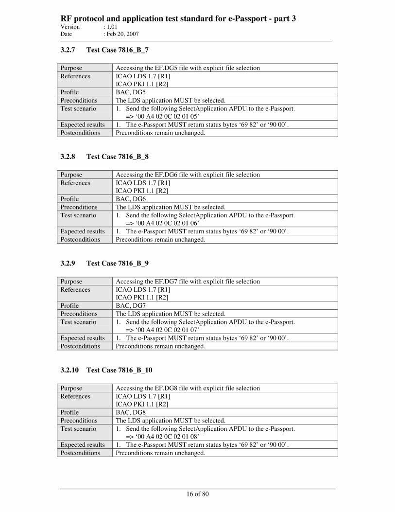
RF protocol and application test standard for e-Passport - part 3 Version : 1.01
Date : Feb 20, 2007
16 of 80
3.2.7 Test Case 7816_B_7
Purpose Accessing the EF.DG5 file with explicit file selection
References ICAO LDS 1.7 [R1]
ICAO PKI 1.1 [R2]
Profile BAC, DG5
Preconditions The LDS application MUST be selected.
Test scenario 1. Send the following SelectApplication APDU to the e-Passport.
=> ‘00 A4 02 0C 02 01 05’
Expected results 1. The e-Passport MUST return status bytes ‘69 82’ or ‘90 00’.
Postconditions Preconditions remain unchanged.
3.2.8 Test Case 7816_B_8
Purpose Accessing the EF.DG6 file with explicit file selection
References ICAO LDS 1.7 [R1]
ICAO PKI 1.1 [R2]
Profile BAC, DG6
Preconditions The LDS application MUST be selected.
Test scenario 1. Send the following SelectApplication APDU to the e-Passport.
=> ‘00 A4 02 0C 02 01 06’
Expected results 1. The e-Passport MUST return status bytes ‘69 82’ or ‘90 00’.
Postconditions Preconditions remain unchanged.
3.2.9 Test Case 7816_B_9
Purpose Accessing the EF.DG7 file with explicit file selection
References ICAO LDS 1.7 [R1]
ICAO PKI 1.1 [R2]
Profile BAC, DG7
Preconditions The LDS application MUST be selected.
Test scenario 1. Send the following SelectApplication APDU to the e-Passport.
=> ‘00 A4 02 0C 02 01 07’
Expected results 1. The e-Passport MUST return status bytes ‘69 82’ or ‘90 00’.
Postconditions Preconditions remain unchanged.
3.2.10 Test Case 7816_B_10
Purpose Accessing the EF.DG8 file with explicit file selection
References ICAO LDS 1.7 [R1]
ICAO PKI 1.1 [R2]
Profile BAC, DG8
Preconditions The LDS application MUST be selected.
Test scenario 1. Send the following SelectApplication APDU to the e-Passport.
=> ‘00 A4 02 0C 02 01 08’
Expected results 1. The e-Passport MUST return status bytes ‘69 82’ or ‘90 00’.
Postconditions Preconditions remain unchanged.

RF protocol and application test standard for e-Passport - part 3 Version : 1.01
Date : Feb 20, 2007
17 of 80
3.2.11 Test Case 7816_B_11
Purpose Accessing the EF.DG9 file with explicit file selection
References ICAO LDS 1.7 [R1]
ICAO PKI 1.1 [R2]
Profile BAC, DG9
Preconditions The LDS application MUST be selected.
Test scenario 1. Send the following SelectApplication APDU to the e-Passport.
=> ‘00 A4 02 0C 02 01 09’
Expected results 1. The e-Passport MUST return status bytes ‘69 82’ or ‘90 00’.
Postconditions Preconditions remain unchanged.
3.2.12 Test Case 7816_B_12
Purpose Accessing the EF.DG10 file with explicit file selection
References ICAO LDS 1.7 [R1]
ICAO PKI 1.1 [R2]
Profile BAC, DG10
Preconditions The LDS application MUST be selected.
Test scenario 1. Send the following SelectApplication APDU to the e-Passport.
=> ‘00 A4 02 0C 02 01 0A’
Expected results 1. The e-Passport MUST return status bytes ‘69 82’ or ‘90 00’.
Postconditions Preconditions remain unchanged.
3.2.13 Test Case 7816_B_13
Purpose Accessing the EF.DG11 file with explicit file selection
References ICAO LDS 1.7 [R1]
ICAO PKI 1.1 [R2]
Profile BAC, DG11
Preconditions The LDS application MUST be selected.
Test scenario 1. Send the following SelectApplication APDU to the e-Passport.
=> ‘00 A4 02 0C 02 01 0B’
Expected results 1. The e-Passport MUST return status bytes ‘69 82’ or ‘90 00’.
Postconditions Preconditions remain unchanged.
3.2.14 Test Case 7816_B_14
Purpose Accessing the EF.DG12 file with explicit file selection
References ICAO LDS 1.7 [R1]
ICAO PKI 1.1 [R2]
Profile BAC, DG12
Preconditions The LDS application MUST be selected.
Test scenario 1. Send the following SelectApplication APDU to the e-Passport.
=> ‘00 A4 02 0C 02 01 0C’
Expected results 1. The e-Passport MUST return status bytes ‘69 82’ or ‘90 00’.
Postconditions Preconditions remain unchanged.

RF protocol and application test standard for e-Passport - part 3 Version : 1.01
Date : Feb 20, 2007
18 of 80
3.2.15 Test Case 7816_B_15
Purpose Accessing the EF.DG13 file with explicit file selection
References ICAO LDS 1.7 [R1]
ICAO PKI 1.1 [R2]
Profile BAC, DG13
Preconditions The LDS application MUST be selected.
Test scenario 1. Send the following SelectApplication APDU to the e-Passport.
=> ‘00 A4 02 0C 02 01 0D’
Expected results 1. The e-Passport MUST return status bytes ‘69 82’ or ‘90 00’.
Postconditions Preconditions remain unchanged.
3.2.16 Test Case 7816_B_16
Purpose Accessing the EF.DG14 file with explicit file selection
References ICAO LDS 1.7 [R1]
ICAO PKI 1.1 [R2]
Profile BAC, EAC
Preconditions The LDS application MUST be selected.
Test scenario 1. Send the following SelectApplication APDU to the e-Passport.
=> ‘00 A4 02 0C 02 01 0E’
Expected results 1. The e-Passport MUST return status bytes ‘69 82’ or ‘90 00’.
Postconditions Preconditions remain unchanged.
3.2.17 Test Case 7816_B_17
Purpose Accessing the EF.DG15 file with explicit file selection
References ICAO LDS 1.7 [R1]
ICAO PKI 1.1 [R2]
Profile BAC, AA
Preconditions The LDS application MUST be selected.
Test scenario 1. Send the following SelectApplication APDU to the e-Passport.
=> ‘00 A4 02 0C 02 01 0F’
Expected results 1. The e-Passport MUST return status bytes ‘69 82’ or ‘90 00’.
Postconditions Preconditions remain unchanged.
3.2.18 Test Case 7816_B_18
Purpose Accessing the EF.DG16 file with explicit file selection
References ICAO LDS 1.7 [R1]
ICAO PKI 1.1 [R2]
Profile BAC, DG16
Preconditions The LDS application MUST be selected.
Test scenario 1. Send the following SelectApplication APDU to the e-Passport.
=> ‘00 A4 02 0C 02 01 10’
Expected results 1. The e-Passport MUST return status bytes ‘69 82’ or ‘90 00’.
Postconditions Preconditions remain unchanged.

RF protocol and application test standard for e-Passport - part 3 Version : 1.01
Date : Feb 20, 2007
19 of 80
3.2.19 Test Case 7816_B_19
Purpose Accessing the EF.COM file with implicit file selection (ReadBinary with SFI)
References ICAO LDS 1.7 [R1]
ICAO PKI 1.1 [R2]
Profile BAC
Preconditions The LDS application MUST be selected.
Test scenario 1. Send the ReadBinary APDU to the e-Passport.
=> ‘00 B0 9E 00 00’
Expected results 1. Since read access is prohibited without BAC, the response data field MUST
be empty. The e-Passport MUST return status bytes ‘69 82’.
Postconditions Preconditions remain unchanged.
3.2.20 Test Case 7816_B_20
Purpose Accessing the EF.SOD file with implicit file selection (ReadBinary with SFI)
References ICAO LDS 1.7 [R1]
ICAO PKI 1.1 [R2]
Profile BAC
Preconditions The LDS application MUST be selected.
Test scenario 1. Send the ReadBinary APDU to the e-Passport.
=> ‘00 B0 9D 00 00’
Expected results 1. Since read access is prohibited without BAC, the response data field MUST
be empty. The e-Passport MUST return status bytes ‘69 82’.
Postconditions Preconditions remain unchanged.
3.2.21 Test Case 7816_B_21
Purpose Accessing the EF.DG1 file with implicit file selection (ReadBinary with SFI)
References ICAO LDS 1.7 [R1]
ICAO PKI 1.1 [R2]
Profile BAC
Preconditions The LDS application MUST be selected.
Test scenario 1. Send the ReadBinary APDU to the e-Passport.
=> ‘00 B0 81 00 00’
Expected results 1. Since read access is prohibited without BAC, the response data field MUST
be empty. The e-Passport MUST return status bytes ‘69 82’.
Postconditions Preconditions remain unchanged.
3.2.22 Test Case 7816_B_22
Purpose Accessing the EF.DG2 file with implicit file selection (ReadBinary with SFI)
References ICAO LDS 1.7 [R1]
ICAO PKI 1.1 [R2]
Profile BAC
Preconditions The LDS application MUST be selected.
Test scenario 1. Send the ReadBinary APDU to the e-Passport.
=> ‘00 B0 82 00 00’
Expected results 1. Since read access is prohibited without BAC, the response data field MUST
be empty. The e-Passport MUST return status bytes ‘69 82’.
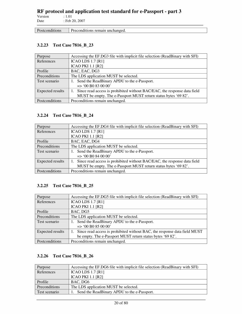
RF protocol and application test standard for e-Passport - part 3 Version : 1.01
Date : Feb 20, 2007
20 of 80
Postconditions Preconditions remain unchanged.
3.2.23 Test Case 7816_B_23
Purpose Accessing the EF.DG3 file with implicit file selection (ReadBinary with SFI)
References ICAO LDS 1.7 [R1]
ICAO PKI 1.1 [R2]
Profile BAC, EAC, DG3
Preconditions The LDS application MUST be selected.
Test scenario 1. Send the ReadBinary APDU to the e-Passport.
=> ‘00 B0 83 00 00’
Expected results 1. Since read access is prohibited without BAC/EAC, the response data field
MUST be empty. The e-Passport MUST return status bytes ‘69 82’.
Postconditions Preconditions remain unchanged.
3.2.24 Test Case 7816_B_24
Purpose Accessing the EF.DG4 file with implicit file selection (ReadBinary with SFI)
References ICAO LDS 1.7 [R1]
ICAO PKI 1.1 [R2]
Profile BAC, EAC, DG4
Preconditions The LDS application MUST be selected.
Test scenario 1. Send the ReadBinary APDU to the e-Passport.
=> ‘00 B0 84 00 00’
Expected results 1. Since read access is prohibited without BAC/EAC, the response data field
MUST be empty. The e-Passport MUST return status bytes ‘69 82’.
Postconditions Preconditions remain unchanged.
3.2.25 Test Case 7816_B_25
Purpose Accessing the EF.DG5 file with implicit file selection (ReadBinary with SFI)
References ICAO LDS 1.7 [R1]
ICAO PKI 1.1 [R2]
Profile BAC, DG5
Preconditions The LDS application MUST be selected.
Test scenario 1. Send the ReadBinary APDU to the e-Passport.
=> ‘00 B0 85 00 00’
Expected results 1. Since read access is prohibited without BAC, the response data field MUST
be empty. The e-Passport MUST return status bytes ‘69 82’.
Postconditions Preconditions remain unchanged.
3.2.26 Test Case 7816_B_26
Purpose Accessing the EF.DG6 file with implicit file selection (ReadBinary with SFI)
References ICAO LDS 1.7 [R1]
ICAO PKI 1.1 [R2]
Profile BAC, DG6
Preconditions The LDS application MUST be selected.
Test scenario 1. Send the ReadBinary APDU to the e-Passport.
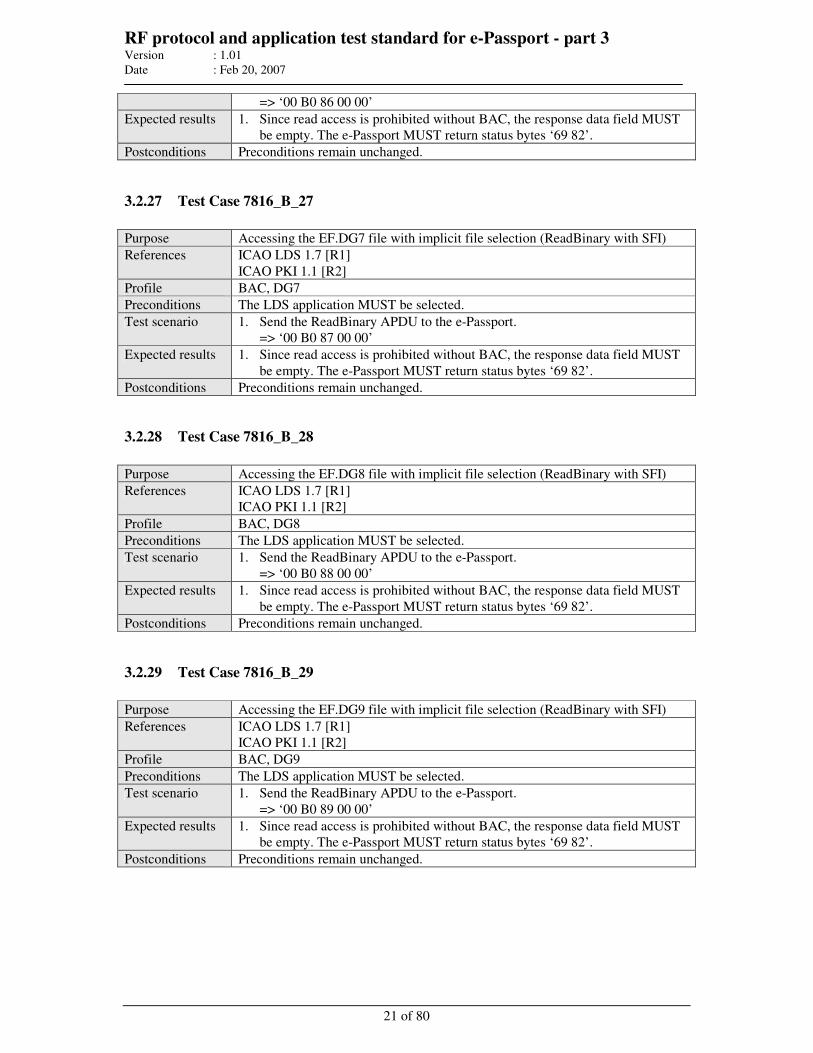
RF protocol and application test standard for e-Passport - part 3 Version : 1.01
Date : Feb 20, 2007
21 of 80
=> ‘00 B0 86 00 00’
Expected results 1. Since read access is prohibited without BAC, the response data field MUST
be empty. The e-Passport MUST return status bytes ‘69 82’.
Postconditions Preconditions remain unchanged.
3.2.27 Test Case 7816_B_27
Purpose Accessing the EF.DG7 file with implicit file selection (ReadBinary with SFI)
References ICAO LDS 1.7 [R1]
ICAO PKI 1.1 [R2]
Profile BAC, DG7
Preconditions The LDS application MUST be selected.
Test scenario 1. Send the ReadBinary APDU to the e-Passport.
=> ‘00 B0 87 00 00’
Expected results 1. Since read access is prohibited without BAC, the response data field MUST
be empty. The e-Passport MUST return status bytes ‘69 82’.
Postconditions Preconditions remain unchanged.
3.2.28 Test Case 7816_B_28
Purpose Accessing the EF.DG8 file with implicit file selection (ReadBinary with SFI)
References ICAO LDS 1.7 [R1]
ICAO PKI 1.1 [R2]
Profile BAC, DG8
Preconditions The LDS application MUST be selected.
Test scenario 1. Send the ReadBinary APDU to the e-Passport.
=> ‘00 B0 88 00 00’
Expected results 1. Since read access is prohibited without BAC, the response data field MUST
be empty. The e-Passport MUST return status bytes ‘69 82’.
Postconditions Preconditions remain unchanged.
3.2.29 Test Case 7816_B_29
Purpose Accessing the EF.DG9 file with implicit file selection (ReadBinary with SFI)
References ICAO LDS 1.7 [R1]
ICAO PKI 1.1 [R2]
Profile BAC, DG9
Preconditions The LDS application MUST be selected.
Test scenario 1. Send the ReadBinary APDU to the e-Passport.
=> ‘00 B0 89 00 00’
Expected results 1. Since read access is prohibited without BAC, the response data field MUST
be empty. The e-Passport MUST return status bytes ‘69 82’.
Postconditions Preconditions remain unchanged.
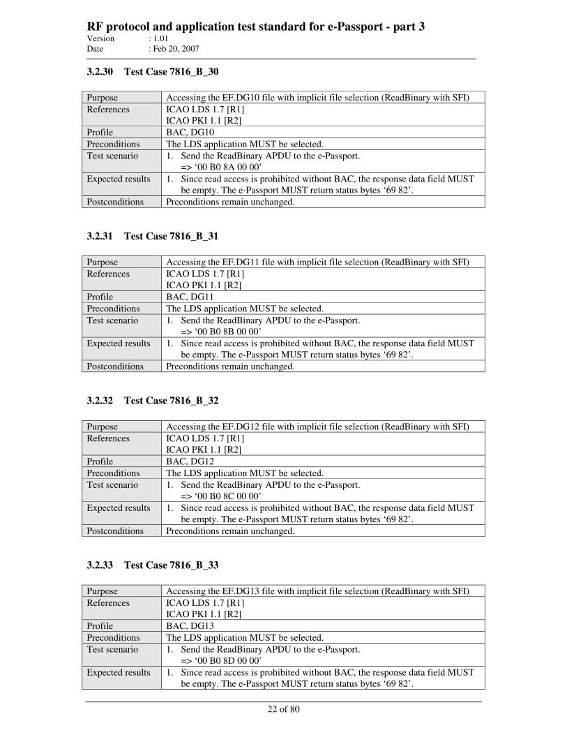
RF protocol and application test standard for e-Passport - part 3 Version : 1.01
Date : Feb 20, 2007
22 of 80
3.2.30 Test Case 7816_B_30
Purpose Accessing the EF.DG10 file with implicit file selection (ReadBinary with SFI)
References ICAO LDS 1.7 [R1]
ICAO PKI 1.1 [R2]
Profile BAC, DG10
Preconditions The LDS application MUST be selected.
Test scenario 1. Send the ReadBinary APDU to the e-Passport.
=> ‘00 B0 8A 00 00’
Expected results 1. Since read access is prohibited without BAC, the response data field MUST
be empty. The e-Passport MUST return status bytes ‘69 82’.
Postconditions Preconditions remain unchanged.
3.2.31 Test Case 7816_B_31
Purpose Accessing the EF.DG11 file with implicit file selection (ReadBinary with SFI)
References ICAO LDS 1.7 [R1]
ICAO PKI 1.1 [R2]
Profile BAC, DG11
Preconditions The LDS application MUST be selected.
Test scenario 1. Send the ReadBinary APDU to the e-Passport.
=> ‘00 B0 8B 00 00’
Expected results 1. Since read access is prohibited without BAC, the response data field MUST
be empty. The e-Passport MUST return status bytes ‘69 82’.
Postconditions Preconditions remain unchanged.
3.2.32 Test Case 7816_B_32
Purpose Accessing the EF.DG12 file with implicit file selection (ReadBinary with SFI)
References ICAO LDS 1.7 [R1]
ICAO PKI 1.1 [R2]
Profile BAC, DG12
Preconditions The LDS application MUST be selected.
Test scenario 1. Send the ReadBinary APDU to the e-Passport.
=> ‘00 B0 8C 00 00’
Expected results 1. Since read access is prohibited without BAC, the response data field MUST
be empty. The e-Passport MUST return status bytes ‘69 82’.
Postconditions Preconditions remain unchanged.
3.2.33 Test Case 7816_B_33
Purpose Accessing the EF.DG13 file with implicit file selection (ReadBinary with SFI)
References ICAO LDS 1.7 [R1]
ICAO PKI 1.1 [R2]
Profile BAC, DG13
Preconditions The LDS application MUST be selected.
Test scenario 1. Send the ReadBinary APDU to the e-Passport.
=> ‘00 B0 8D 00 00’
Expected results 1. Since read access is prohibited without BAC, the response data field MUST
be empty. The e-Passport MUST return status bytes ‘69 82’.
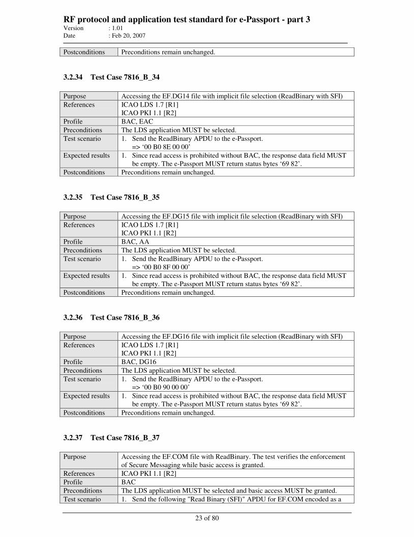
RF protocol and application test standard for e-Passport - part 3 Version : 1.01
Date : Feb 20, 2007
23 of 80
Postconditions Preconditions remain unchanged.
3.2.34 Test Case 7816_B_34
Purpose Accessing the EF.DG14 file with implicit file selection (ReadBinary with SFI)
References ICAO LDS 1.7 [R1]
ICAO PKI 1.1 [R2]
Profile BAC, EAC
Preconditions The LDS application MUST be selected.
Test scenario 1. Send the ReadBinary APDU to the e-Passport.
=> ‘00 B0 8E 00 00’
Expected results 1. Since read access is prohibited without BAC, the response data field MUST
be empty. The e-Passport MUST return status bytes ‘69 82’.
Postconditions Preconditions remain unchanged.
3.2.35 Test Case 7816_B_35
Purpose Accessing the EF.DG15 file with implicit file selection (ReadBinary with SFI)
References ICAO LDS 1.7 [R1]
ICAO PKI 1.1 [R2]
Profile BAC, AA
Preconditions The LDS application MUST be selected.
Test scenario 1. Send the ReadBinary APDU to the e-Passport.
=> ‘00 B0 8F 00 00’
Expected results 1. Since read access is prohibited without BAC, the response data field MUST
be empty. The e-Passport MUST return status bytes ‘69 82’.
Postconditions Preconditions remain unchanged.
3.2.36 Test Case 7816_B_36
Purpose Accessing the EF.DG16 file with implicit file selection (ReadBinary with SFI)
References ICAO LDS 1.7 [R1]
ICAO PKI 1.1 [R2]
Profile BAC, DG16
Preconditions The LDS application MUST be selected.
Test scenario 1. Send the ReadBinary APDU to the e-Passport.
=> ‘00 B0 90 00 00’
Expected results 1. Since read access is prohibited without BAC, the response data field MUST
be empty. The e-Passport MUST return status bytes ‘69 82’.
Postconditions Preconditions remain unchanged.
3.2.37 Test Case 7816_B_37
Purpose Accessing the EF.COM file with ReadBinary. The test verifies the enforcement
of Secure Messaging while basic access is granted.
References ICAO PKI 1.1 [R2]
Profile BAC
Preconditions The LDS application MUST be selected and basic access MUST be granted.
Test scenario 1. Send the following "Read Binary (SFI)" APDU for EF.COM encoded as a
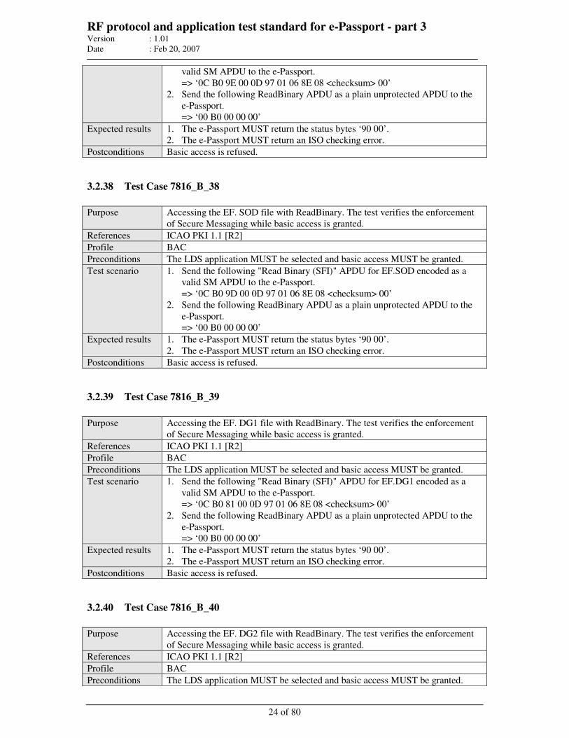
RF protocol and application test standard for e-Passport - part 3 Version : 1.01
Date : Feb 20, 2007
24 of 80
valid SM APDU to the e-Passport.
=> ‘0C B0 9E 00 0D 97 01 06 8E 08 <checksum> 00’
2. Send the following ReadBinary APDU as a plain unprotected APDU to the
e-Passport.
=> ‘00 B0 00 00 00’
Expected results 1. The e-Passport MUST return the status bytes ‘90 00’.
2. The e-Passport MUST return an ISO checking error.
Postconditions Basic access is refused.
3.2.38 Test Case 7816_B_38
Purpose Accessing the EF. SOD file with ReadBinary. The test verifies the enforcement
of Secure Messaging while basic access is granted.
References ICAO PKI 1.1 [R2]
Profile BAC
Preconditions The LDS application MUST be selected and basic access MUST be granted.
Test scenario 1. Send the following "Read Binary (SFI)" APDU for EF.SOD encoded as a
valid SM APDU to the e-Passport.
=> ‘0C B0 9D 00 0D 97 01 06 8E 08 <checksum> 00’
2. Send the following ReadBinary APDU as a plain unprotected APDU to the
e-Passport.
=> ‘00 B0 00 00 00’
Expected results 1. The e-Passport MUST return the status bytes ‘90 00’.
2. The e-Passport MUST return an ISO checking error.
Postconditions Basic access is refused.
3.2.39 Test Case 7816_B_39
Purpose Accessing the EF. DG1 file with ReadBinary. The test verifies the enforcement
of Secure Messaging while basic access is granted.
References ICAO PKI 1.1 [R2]
Profile BAC
Preconditions The LDS application MUST be selected and basic access MUST be granted.
Test scenario 1. Send the following "Read Binary (SFI)" APDU for EF.DG1 encoded as a
valid SM APDU to the e-Passport.
=> ‘0C B0 81 00 0D 97 01 06 8E 08 <checksum> 00’
2. Send the following ReadBinary APDU as a plain unprotected APDU to the
e-Passport.
=> ‘00 B0 00 00 00’
Expected results 1. The e-Passport MUST return the status bytes ‘90 00’.
2. The e-Passport MUST return an ISO checking error.
Postconditions Basic access is refused.
3.2.40 Test Case 7816_B_40
Purpose Accessing the EF. DG2 file with ReadBinary. The test verifies the enforcement
of Secure Messaging while basic access is granted.
References ICAO PKI 1.1 [R2]
Profile BAC
Preconditions The LDS application MUST be selected and basic access MUST be granted.
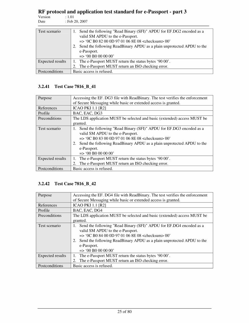
RF protocol and application test standard for e-Passport - part 3 Version : 1.01
Date : Feb 20, 2007
25 of 80
Test scenario 1. Send the following "Read Binary (SFI)" APDU for EF.DG2 encoded as a
valid SM APDU to the e-Passport.
=> ‘0C B0 82 00 0D 97 01 06 8E 08 <checksum> 00’
2. Send the following ReadBinary APDU as a plain unprotected APDU to the
e-Passport.
=> ‘00 B0 00 00 00’
Expected results 1. The e-Passport MUST return the status bytes ‘90 00’.
2. The e-Passport MUST return an ISO checking error.
Postconditions Basic access is refused.
3.2.41 Test Case 7816_B_41
Purpose Accessing the EF. DG3 file with ReadBinary. The test verifies the enforcement
of Secure Messaging while basic or extended access is granted.
References ICAO PKI 1.1 [R2]
Profile BAC, EAC, DG3
Preconditions The LDS application MUST be selected and basic (extended) access MUST be
granted.
Test scenario 1. Send the following "Read Binary (SFI)" APDU for EF.DG3 encoded as a
valid SM APDU to the e-Passport.
=> ‘0C B0 83 00 0D 97 01 06 8E 08 <checksum> 00’
2. Send the following ReadBinary APDU as a plain unprotected APDU to the
e-Passport.
=> ‘00 B0 00 00 00’
Expected results 1. The e-Passport MUST return the status bytes ‘90 00’.
2. The e-Passport MUST return an ISO checking error.
Postconditions Basic access is refused.
3.2.42 Test Case 7816_B_42
Purpose Accessing the EF. DG4 file with ReadBinary. The test verifies the enforcement
of Secure Messaging while basic or extended access is granted.
References ICAO PKI 1.1 [R2]
Profile BAC, EAC, DG4
Preconditions The LDS application MUST be selected and basic (extended) access MUST be
granted.
Test scenario 1. Send the following "Read Binary (SFI)" APDU for EF.DG4 encoded as a
valid SM APDU to the e-Passport.
=> ‘0C B0 84 00 0D 97 01 06 8E 08 <checksum> 00’
2. Send the following ReadBinary APDU as a plain unprotected APDU to the
e-Passport.
=> ‘00 B0 00 00 00’
Expected results 1. The e-Passport MUST return the status bytes ‘90 00’.
2. The e-Passport MUST return an ISO checking error.
Postconditions Basic access is refused.
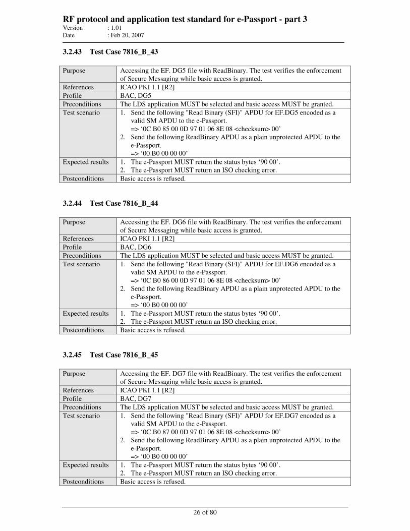
RF protocol and application test standard for e-Passport - part 3 Version : 1.01
Date : Feb 20, 2007
26 of 80
3.2.43 Test Case 7816_B_43
Purpose Accessing the EF. DG5 file with ReadBinary. The test verifies the enforcement
of Secure Messaging while basic access is granted.
References ICAO PKI 1.1 [R2]
Profile BAC, DG5
Preconditions The LDS application MUST be selected and basic access MUST be granted.
Test scenario 1. Send the following "Read Binary (SFI)" APDU for EF.DG5 encoded as a
valid SM APDU to the e-Passport.
=> ‘0C B0 85 00 0D 97 01 06 8E 08 <checksum> 00’
2. Send the following ReadBinary APDU as a plain unprotected APDU to the
e-Passport.
=> ‘00 B0 00 00 00’
Expected results 1. The e-Passport MUST return the status bytes ‘90 00’.
2. The e-Passport MUST return an ISO checking error.
Postconditions Basic access is refused.
3.2.44 Test Case 7816_B_44
Purpose Accessing the EF. DG6 file with ReadBinary. The test verifies the enforcement
of Secure Messaging while basic access is granted.
References ICAO PKI 1.1 [R2]
Profile BAC, DG6
Preconditions The LDS application MUST be selected and basic access MUST be granted.
Test scenario 1. Send the following "Read Binary (SFI)" APDU for EF.DG6 encoded as a
valid SM APDU to the e-Passport.
=> ‘0C B0 86 00 0D 97 01 06 8E 08 <checksum> 00’
2. Send the following ReadBinary APDU as a plain unprotected APDU to the
e-Passport.
=> ‘00 B0 00 00 00’
Expected results 1. The e-Passport MUST return the status bytes ‘90 00’.
2. The e-Passport MUST return an ISO checking error.
Postconditions Basic access is refused.
3.2.45 Test Case 7816_B_45
Purpose Accessing the EF. DG7 file with ReadBinary. The test verifies the enforcement
of Secure Messaging while basic access is granted.
References ICAO PKI 1.1 [R2]
Profile BAC, DG7
Preconditions The LDS application MUST be selected and basic access MUST be granted.
Test scenario 1. Send the following "Read Binary (SFI)" APDU for EF.DG7 encoded as a
valid SM APDU to the e-Passport.
=> ‘0C B0 87 00 0D 97 01 06 8E 08 <checksum> 00’
2. Send the following ReadBinary APDU as a plain unprotected APDU to the
e-Passport.
=> ‘00 B0 00 00 00’
Expected results 1. The e-Passport MUST return the status bytes ‘90 00’.
2. The e-Passport MUST return an ISO checking error.
Postconditions Basic access is refused.
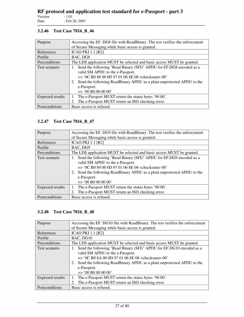
RF protocol and application test standard for e-Passport - part 3 Version : 1.01
Date : Feb 20, 2007
27 of 80
3.2.46 Test Case 7816_B_46
Purpose Accessing the EF. DG8 file with ReadBinary. The test verifies the enforcement
of Secure Messaging while basic access is granted.
References ICAO PKI 1.1 [R2]
Profile BAC, DG8
Preconditions The LDS application MUST be selected and basic access MUST be granted.
Test scenario 1. Send the following "Read Binary (SFI)" APDU for EF.DG8 encoded as a
valid SM APDU to the e-Passport.
=> ‘0C B0 88 00 0D 97 01 06 8E 08 <checksum> 00’
2. Send the following ReadBinary APDU as a plain unprotected APDU to the
e-Passport.
=> ‘00 B0 00 00 00’
Expected results 1. The e-Passport MUST return the status bytes ‘90 00’.
2. The e-Passport MUST return an ISO checking error.
Postconditions Basic access is refused.
3.2.47 Test Case 7816_B_47
Purpose Accessing the EF. DG9 file with ReadBinary. The test verifies the enforcement
of Secure Messaging while basic access is granted.
References ICAO PKI 1.1 [R2]
Profile BAC, DG9
Preconditions The LDS application MUST be selected and basic access MUST be granted.
Test scenario 1. Send the following "Read Binary (SFI)" APDU for EF.DG9 encoded as a
valid SM APDU to the e-Passport.
=> ‘0C B0 89 00 0D 97 01 06 8E 08 <checksum> 00’
2. Send the following ReadBinary APDU as a plain unprotected APDU to the
e-Passport.
=> ‘00 B0 00 00 00’
Expected results 1. The e-Passport MUST return the status bytes ‘90 00’.
2. The e-Passport MUST return an ISO checking error.
Postconditions Basic access is refused.
3.2.48 Test Case 7816_B_48
Purpose Accessing the EF. DG10 file with ReadBinary. The test verifies the enforcement
of Secure Messaging while basic access is granted.
References ICAO PKI 1.1 [R2]
Profile BAC, DG10
Preconditions The LDS application MUST be selected and basic access MUST be granted.
Test scenario 1. Send the following "Read Binary (SFI)" APDU for EF.DG10 encoded as a
valid SM APDU to the e-Passport.
=> ‘0C B0 8A 00 0D 97 01 06 8E 08 <checksum> 00’
2. Send the following ReadBinary APDU as a plain unprotected APDU to the
e-Passport.
=> ‘00 B0 00 00 00’
Expected results 1. The e-Passport MUST return the status bytes ‘90 00’.
2. The e-Passport MUST return an ISO checking error.
Postconditions Basic access is refused.

RF protocol and application test standard for e-Passport - part 3 Version : 1.01
Date : Feb 20, 2007
28 of 80
3.2.49 Test Case 7816_B_49
Purpose Accessing the EF. DG11 file with ReadBinary. The test verifies the enforcement
of Secure Messaging while basic access is granted.
References ICAO PKI 1.1 [R2]
Profile BAC, DG11
Preconditions The LDS application MUST be selected and basic access MUST be granted.
Test scenario 1. Send the following "Read Binary (SFI)" APDU for EF.DG11 encoded as a
valid SM APDU to the e-Passport.
=> ‘0C B0 8B 00 0D 97 01 06 8E 08 <checksum> 00’
2. Send the following ReadBinary APDU as a plain unprotected APDU to the
e-Passport.
=> ‘00 B0 00 00 00’
Expected results 1. The e-Passport MUST return the status bytes ‘90 00’.
2. The e-Passport MUST return an ISO checking error.
Postconditions Basic access is refused.
3.2.50 Test Case 7816_B_50
Purpose Accessing the EF. DG12 file with ReadBinary. The test verifies the enforcement
of Secure Messaging while basic access is granted.
References ICAO PKI 1.1 [R2]
Profile BAC, DG12
Preconditions The LDS application MUST be selected and basic access MUST be granted.
Test scenario 1. Send the following "Read Binary (SFI)" APDU for EF.DG12 encoded as a
valid SM APDU to the e-Passport.
=> ‘0C B0 8C 00 0D 97 01 06 8E 08 <checksum> 00’
2. Send the following ReadBinary APDU as a plain unprotected APDU to the
e-Passport.
=> ‘00 B0 00 00 00’
Expected results 1. The e-Passport MUST return the status bytes ‘90 00’.
2. The e-Passport MUST return an ISO checking error.
Postconditions Basic access is refused.
3.2.51 Test Case 7816_B_51
Purpose Accessing the EF. DG13 file with ReadBinary. The test verifies the enforcement
of Secure Messaging while basic access is granted.
References ICAO PKI 1.1 [R2]
Profile BAC, DG13
Preconditions The LDS application MUST be selected and basic access MUST be granted.
Test scenario 1. Send the following "Read Binary (SFI)" APDU for EF.DG13 encoded as a
valid SM APDU to the e-Passport.
=> ‘0C B0 8D 00 0D 97 01 06 8E 08 <checksum> 00’
2. Send the following ReadBinary APDU as a plain unprotected APDU to the
e-Passport.
=> ‘00 B0 00 00 00’
Expected results 1. The e-Passport MUST return the status bytes ‘90 00’.
2. The e-Passport MUST return an ISO checking error.
Postconditions Basic access is refused.
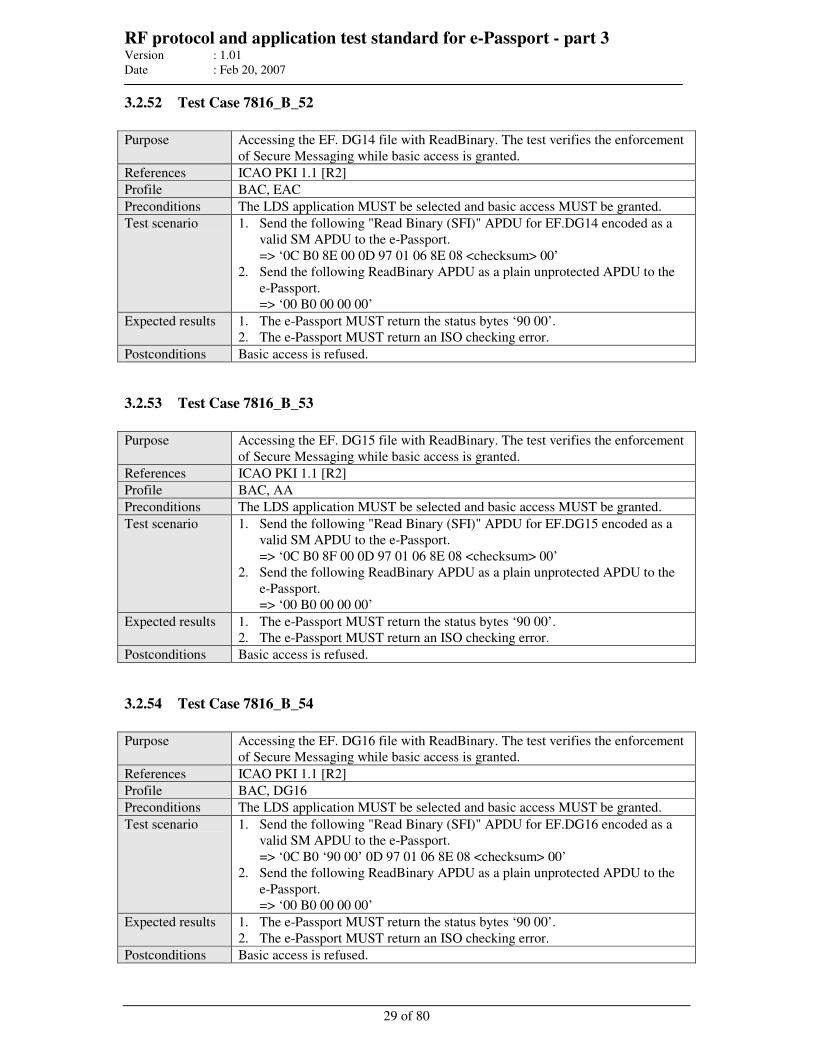
RF protocol and application test standard for e-Passport - part 3 Version : 1.01
Date : Feb 20, 2007
29 of 80
3.2.52 Test Case 7816_B_52
Purpose Accessing the EF. DG14 file with ReadBinary. The test verifies the enforcement
of Secure Messaging while basic access is granted.
References ICAO PKI 1.1 [R2]
Profile BAC, EAC
Preconditions The LDS application MUST be selected and basic access MUST be granted.
Test scenario 1. Send the following "Read Binary (SFI)" APDU for EF.DG14 encoded as a
valid SM APDU to the e-Passport.
=> ‘0C B0 8E 00 0D 97 01 06 8E 08 <checksum> 00’
2. Send the following ReadBinary APDU as a plain unprotected APDU to the
e-Passport.
=> ‘00 B0 00 00 00’
Expected results 1. The e-Passport MUST return the status bytes ‘90 00’.
2. The e-Passport MUST return an ISO checking error.
Postconditions Basic access is refused.
3.2.53 Test Case 7816_B_53
Purpose Accessing the EF. DG15 file with ReadBinary. The test verifies the enforcement
of Secure Messaging while basic access is granted.
References ICAO PKI 1.1 [R2]
Profile BAC, AA
Preconditions The LDS application MUST be selected and basic access MUST be granted.
Test scenario 1. Send the following "Read Binary (SFI)" APDU for EF.DG15 encoded as a
valid SM APDU to the e-Passport.
=> ‘0C B0 8F 00 0D 97 01 06 8E 08 <checksum> 00’
2. Send the following ReadBinary APDU as a plain unprotected APDU to the
e-Passport.
=> ‘00 B0 00 00 00’
Expected results 1. The e-Passport MUST return the status bytes ‘90 00’.
2. The e-Passport MUST return an ISO checking error.
Postconditions Basic access is refused.
3.2.54 Test Case 7816_B_54
Purpose Accessing the EF. DG16 file with ReadBinary. The test verifies the enforcement
of Secure Messaging while basic access is granted.
References ICAO PKI 1.1 [R2]
Profile BAC, DG16
Preconditions The LDS application MUST be selected and basic access MUST be granted.
Test scenario 1. Send the following "Read Binary (SFI)" APDU for EF.DG16 encoded as a
valid SM APDU to the e-Passport.
=> ‘0C B0 ‘90 00’ 0D 97 01 06 8E 08 <checksum> 00’
2. Send the following ReadBinary APDU as a plain unprotected APDU to the
e-Passport.
=> ‘00 B0 00 00 00’
Expected results 1. The e-Passport MUST return the status bytes ‘90 00’.
2. The e-Passport MUST return an ISO checking error.
Postconditions Basic access is refused.
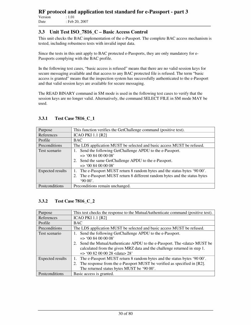
RF protocol and application test standard for e-Passport - part 3 Version : 1.01
Date : Feb 20, 2007
30 of 80
3.3 Unit Test ISO_7816_C – Basic Access Control
This unit checks the BAC implementation of the e-Passport. The complete BAC access mechanism is
tested, including robustness tests with invalid input data.
Since the tests in this unit apply to BAC protected e-Passports, they are only mandatory for e-
Passports complying with the BAC profile.
In the following test cases, “basic access is refused” means that there are no valid session keys for
secure messaging available and that access to any BAC protected file is refused. The term “basic
access is granted” means that the inspection system has successfully authenticated to the e-Passport
and that valid session keys are available for secure messaging.
The READ BINARY command in SM mode is used in the following test cases to verify that the
session keys are no longer valid. Alternatively, the command SELECT FILE in SM mode MAY be
used.
3.3.1 Test Case 7816_C_1
Purpose This function verifies the GetChallenge command (positive test).
References ICAO PKI 1.1 [R2]
Profile BAC
Preconditions The LDS application MUST be selected and basic access MUST be refused.
Test scenario 1. Send the following GetChallenge APDU to the e-Passport.
=> ‘00 84 00 00 08’
2. Send the same GetChallenge APDU to the e-Passport.
=> ‘00 84 00 00 08’
Expected results 1. The e-Passport MUST return 8 random bytes and the status bytes ‘90 00’.
2. The e-Passport MUST return 8 different random bytes and the status bytes
‘90 00’.
Postconditions Preconditions remain unchanged.
3.3.2 Test Case 7816_C_2
Purpose This test checks the response to the MutualAuthenticate command (positive test).
References ICAO PKI 1.1 [R2]
Profile BAC
Preconditions The LDS application MUST be selected and basic access MUST be refused.
Test scenario 1. Send the following GetChallenge APDU to the e-Passport.
=> ‘00 84 00 00 08’
2. Send the MutualAuthenticate APDU to the e-Passport. The <data> MUST be
calculated from the given MRZ data and the challenge returned in step 1.
=> ‘00 82 00 00 28 <data> 28’
Expected results 1. The e-Passport MUST return 8 random bytes and the status bytes ‘90 00’.
2. The response from the e-Passport MUST be verified as specified in [R2].
The returned status bytes MUST be ‘90 00’.
Postconditions Basic access is granted.
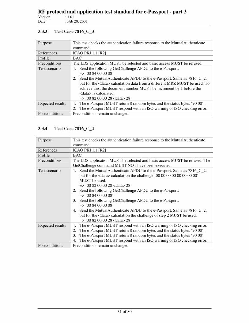
RF protocol and application test standard for e-Passport - part 3 Version : 1.01
Date : Feb 20, 2007
31 of 80
3.3.3 Test Case 7816_C_3
Purpose This test checks the authentication failure response to the MutualAuthenticate
command
References ICAO PKI 1.1 [R2]
Profile BAC
Preconditions The LDS application MUST be selected and basic access MUST be refused.
Test scenario 1. Send the following GetChallenge APDU to the e-Passport.
=> ‘00 84 00 00 08’
2. Send the MutualAuthenticate APDU to the e-Passport. Same as 7816_C_2,
but for the <data> calculation data from a different MRZ MUST be used. To
achieve this, the document number MUST be increment by 1 before the
<data> is calculated.
=> ‘00 82 00 00 28 <data> 28’
Expected results 1. The e-Passport MUST return 8 random bytes and the status bytes ‘90 00’.
2. The e-Passport MUST respond with an ISO warning or ISO checking error.
Postconditions Preconditions remain unchanged.
3.3.4 Test Case 7816_C_4
Purpose This test checks the authentication failure response to the MutualAuthenticate
command
References ICAO PKI 1.1 [R2]
Profile BAC
Preconditions The LDS application MUST be selected and basic access MUST be refused. The
GetChallenge command MUST NOT have been executed.
Test scenario 1. Send the MutualAuthenticate APDU to the e-Passport. Same as 7816_C_2,
but for the <data> calculation the challenge ’00 00 00 00 00 00 00 00’
MUST be used.
=> ‘00 82 00 00 28 <data> 28’
2. Send the following GetChallenge APDU to the e-Passport.
=> ‘00 84 00 00 08’
3. Send the following GetChallenge APDU to the e-Passport.
=> ‘00 84 00 00 08’
4. Send the MutualAuthenticate APDU to the e-Passport. Same as 7816_C_2,
but for the <data> calculation the challenge of step 2 MUST be used.
=> ‘00 82 00 00 28 <data> 28’
Expected results 1. The e-Passport MUST respond with an ISO warning or ISO checking error.
2. The e-Passport MUST return 8 random bytes and the status bytes ‘90 00’.
3. The e-Passport MUST return 8 random bytes and the status bytes ‘90 00’.
4. The e-Passport MUST respond with an ISO warning or ISO checking error.
Postconditions Preconditions remain unchanged.
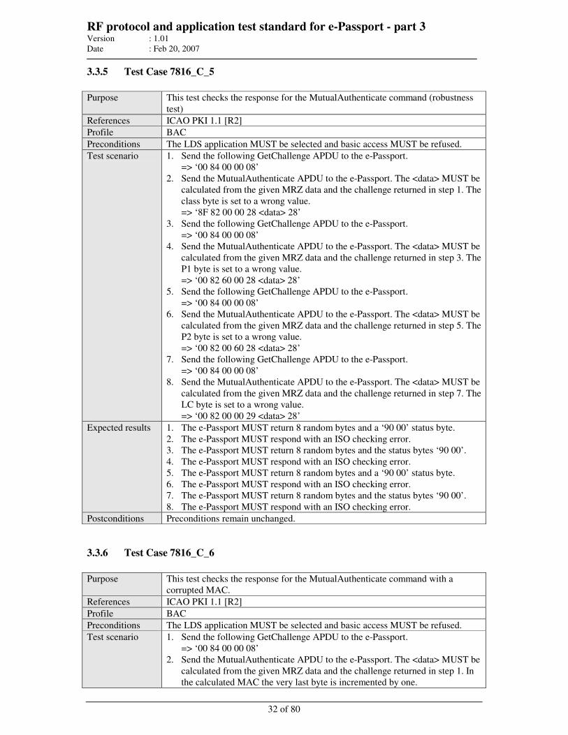
RF protocol and application test standard for e-Passport - part 3 Version : 1.01
Date : Feb 20, 2007
32 of 80
3.3.5 Test Case 7816_C_5
Purpose This test checks the response for the MutualAuthenticate command (robustness
test)
References ICAO PKI 1.1 [R2]
Profile BAC
Preconditions The LDS application MUST be selected and basic access MUST be refused.
Test scenario 1. Send the following GetChallenge APDU to the e-Passport.
=> ‘00 84 00 00 08’
2. Send the MutualAuthenticate APDU to the e-Passport. The <data> MUST be
calculated from the given MRZ data and the challenge returned in step 1. The
class byte is set to a wrong value.
=> ‘8F 82 00 00 28 <data> 28’
3. Send the following GetChallenge APDU to the e-Passport.
=> ‘00 84 00 00 08’
4. Send the MutualAuthenticate APDU to the e-Passport. The <data> MUST be
calculated from the given MRZ data and the challenge returned in step 3. The
P1 byte is set to a wrong value.
=> ‘00 82 60 00 28 <data> 28’
5. Send the following GetChallenge APDU to the e-Passport.
=> ‘00 84 00 00 08’
6. Send the MutualAuthenticate APDU to the e-Passport. The <data> MUST be
calculated from the given MRZ data and the challenge returned in step 5. The
P2 byte is set to a wrong value.
=> ‘00 82 00 60 28 <data> 28’
7. Send the following GetChallenge APDU to the e-Passport.
=> ‘00 84 00 00 08’
8. Send the MutualAuthenticate APDU to the e-Passport. The <data> MUST be
calculated from the given MRZ data and the challenge returned in step 7. The
LC byte is set to a wrong value.
=> ‘00 82 00 00 29 <data> 28’
Expected results 1. The e-Passport MUST return 8 random bytes and a ‘90 00’ status byte.
2. The e-Passport MUST respond with an ISO checking error.
3. The e-Passport MUST return 8 random bytes and the status bytes ‘90 00’.
4. The e-Passport MUST respond with an ISO checking error.
5. The e-Passport MUST return 8 random bytes and a ‘90 00’ status byte.
6. The e-Passport MUST respond with an ISO checking error.
7. The e-Passport MUST return 8 random bytes and the status bytes ‘90 00’.
8. The e-Passport MUST respond with an ISO checking error.
Postconditions Preconditions remain unchanged.
3.3.6 Test Case 7816_C_6
Purpose This test checks the response for the MutualAuthenticate command with a
corrupted MAC.
References ICAO PKI 1.1 [R2]
Profile BAC
Preconditions The LDS application MUST be selected and basic access MUST be refused.
Test scenario 1. Send the following GetChallenge APDU to the e-Passport.
=> ‘00 84 00 00 08’
2. Send the MutualAuthenticate APDU to the e-Passport. The <data> MUST be
calculated from the given MRZ data and the challenge returned in step 1. In
the calculated MAC the very last byte is incremented by one.
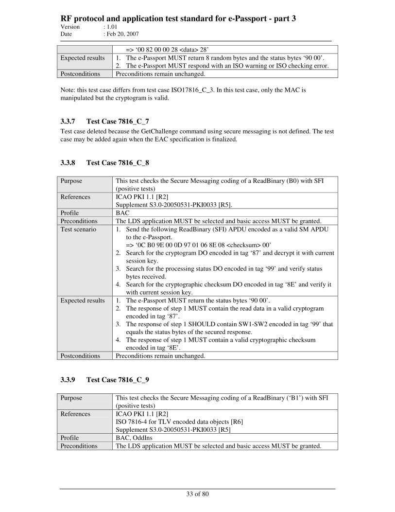
RF protocol and application test standard for e-Passport - part 3 Version : 1.01
Date : Feb 20, 2007
33 of 80
=> ‘00 82 00 00 28 <data> 28’
Expected results 1. The e-Passport MUST return 8 random bytes and the status bytes ‘90 00’.
2. The e-Passport MUST respond with an ISO warning or ISO checking error.
Postconditions Preconditions remain unchanged.
Note: this test case differs from test case ISO17816_C_3. In this test case, only the MAC is
manipulated but the cryptogram is valid.
3.3.7 Test Case 7816_C_7
Test case deleted because the GetChallenge command using secure messaging is not defined. The test
case may be added again when the EAC specification is finalized.
3.3.8 Test Case 7816_C_8
Purpose This test checks the Secure Messaging coding of a ReadBinary (B0) with SFI
(positive tests)
References ICAO PKI 1.1 [R2]
Supplement S3.0-20050531-PKI0033 [R5].
Profile BAC
Preconditions The LDS application MUST be selected and basic access MUST be granted.
Test scenario 1. Send the following ReadBinary (SFI) APDU encoded as a valid SM APDU
to the e-Passport.
=> ‘0C B0 9E 00 0D 97 01 06 8E 08 <checksum> 00’
2. Search for the cryptogram DO encoded in tag ‘87’ and decrypt it with current
session key.
3. Search for the processing status DO encoded in tag ‘99’ and verify status
bytes received.
4. Search for the cryptographic checksum DO encoded in tag ‘8E’ and verify it
with current session key.
Expected results 1. The e-Passport MUST return the status bytes ‘90 00’.
2. The response of step 1 MUST contain the read data in a valid cryptogram
encoded in tag ‘87’.
3. The response of step 1 SHOULD contain SW1-SW2 encoded in tag ‘99’ that
equals the status bytes of the secured response.
4. The response of step 1 MUST contain a valid cryptographic checksum
encoded in tag ‘8E’.
Postconditions Preconditions remain unchanged.
3.3.9 Test Case 7816_C_9
Purpose This test checks the Secure Messaging coding of a ReadBinary (‘B1’) with SFI
(positive tests)
References ICAO PKI 1.1 [R2]
ISO 7816-4 for TLV encoded data objects [R6]
Supplement S3.0-20050531-PKI0033 [R5]
Profile BAC, OddIns
Preconditions The LDS application MUST be selected and basic access MUST be granted.
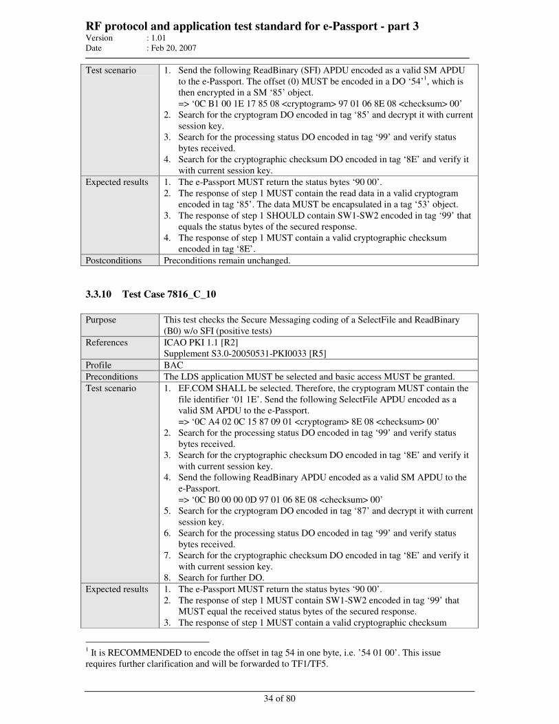
RF protocol and application test standard for e-Passport - part 3 Version : 1.01
Date : Feb 20, 2007
34 of 80
Test scenario 1. Send the following ReadBinary (SFI) APDU encoded as a valid SM APDU
to the e-Passport. The offset (0) MUST be encoded in a DO ‘54’1, which is
then encrypted in a SM ‘85’ object.
=> ‘0C B1 00 1E 17 85 08 <cryptogram> 97 01 06 8E 08 <checksum> 00’
2. Search for the cryptogram DO encoded in tag ‘85’ and decrypt it with current
session key.
3. Search for the processing status DO encoded in tag ‘99’ and verify status
bytes received.
4. Search for the cryptographic checksum DO encoded in tag ‘8E’ and verify it
with current session key.
Expected results 1. The e-Passport MUST return the status bytes ‘90 00’.
2. The response of step 1 MUST contain the read data in a valid cryptogram
encoded in tag ‘85’. The data MUST be encapsulated in a tag ‘53’ object.
3. The response of step 1 SHOULD contain SW1-SW2 encoded in tag ‘99’ that
equals the status bytes of the secured response.
4. The response of step 1 MUST contain a valid cryptographic checksum
encoded in tag ‘8E’.
Postconditions Preconditions remain unchanged.
3.3.10 Test Case 7816_C_10
Purpose This test checks the Secure Messaging coding of a SelectFile and ReadBinary
(B0) w/o SFI (positive tests)
References ICAO PKI 1.1 [R2]
Supplement S3.0-20050531-PKI0033 [R5]
Profile BAC
Preconditions The LDS application MUST be selected and basic access MUST be granted.
Test scenario 1. EF.COM SHALL be selected. Therefore, the cryptogram MUST contain the
file identifier ‘01 1E’. Send the following SelectFile APDU encoded as a
valid SM APDU to the e-Passport.
=> ‘0C A4 02 0C 15 87 09 01 <cryptogram> 8E 08 <checksum> 00’
2. Search for the processing status DO encoded in tag ‘99’ and verify status
bytes received.
3. Search for the cryptographic checksum DO encoded in tag ‘8E’ and verify it
with current session key.
4. Send the following ReadBinary APDU encoded as a valid SM APDU to the
e-Passport.
=> ‘0C B0 00 00 0D 97 01 06 8E 08 <checksum> 00’
5. Search for the cryptogram DO encoded in tag ‘87’ and decrypt it with current
session key.
6. Search for the processing status DO encoded in tag ‘99’ and verify status
bytes received.
7. Search for the cryptographic checksum DO encoded in tag ‘8E’ and verify it
with current session key.
8. Search for further DO.
Expected results 1. The e-Passport MUST return the status bytes ‘90 00’.
2. The response of step 1 MUST contain SW1-SW2 encoded in tag ‘99’ that
MUST equal the received status bytes of the secured response.
3. The response of step 1 MUST contain a valid cryptographic checksum
1 It is RECOMMENDED to encode the offset in tag 54 in one byte, i.e. ’54 01 00’. This issue
requires further clarification and will be forwarded to TF1/TF5.
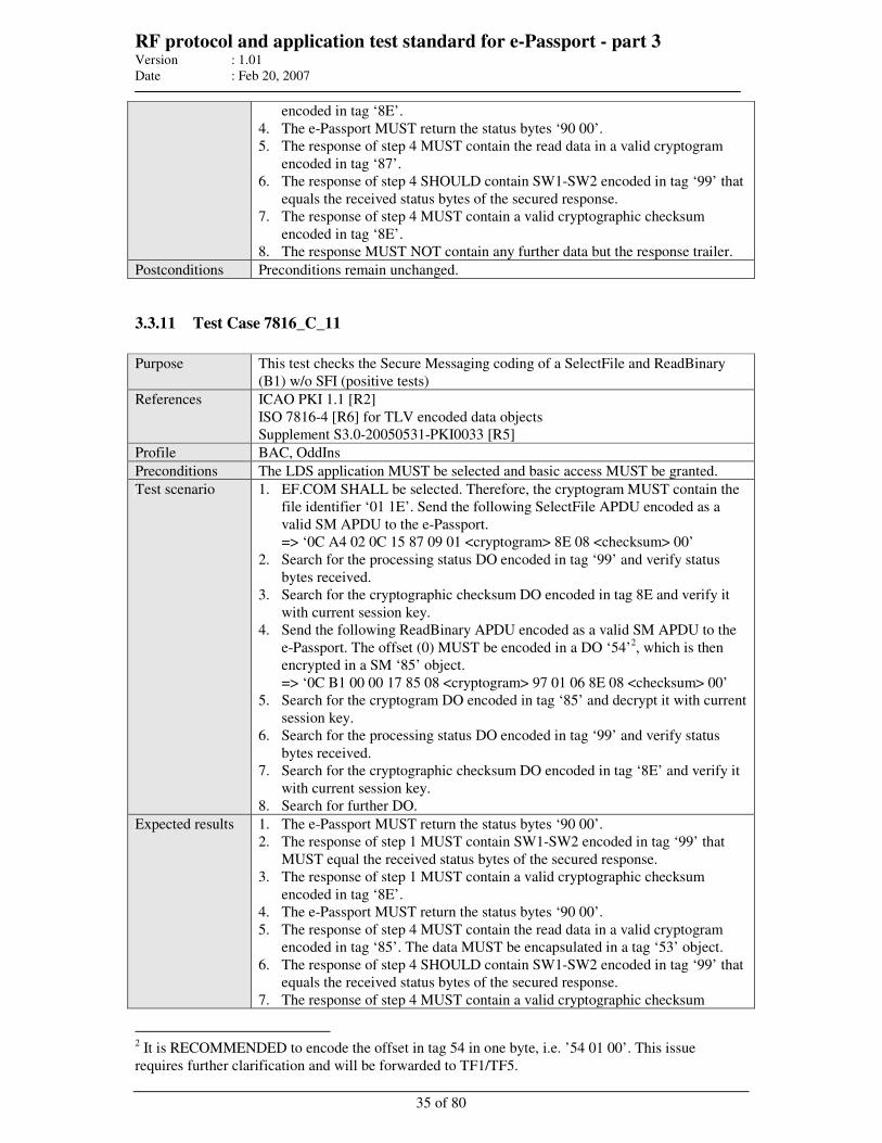
RF protocol and application test standard for e-Passport - part 3 Version : 1.01
Date : Feb 20, 2007
35 of 80
encoded in tag ‘8E’.
4. The e-Passport MUST return the status bytes ‘90 00’.
5. The response of step 4 MUST contain the read data in a valid cryptogram
encoded in tag ‘87’.
6. The response of step 4 SHOULD contain SW1-SW2 encoded in tag ‘99’ that
equals the received status bytes of the secured response.
7. The response of step 4 MUST contain a valid cryptographic checksum
encoded in tag ‘8E’.
8. The response MUST NOT contain any further data but the response trailer.
Postconditions Preconditions remain unchanged.
3.3.11 Test Case 7816_C_11
Purpose This test checks the Secure Messaging coding of a SelectFile and ReadBinary
(B1) w/o SFI (positive tests)
References ICAO PKI 1.1 [R2]
ISO 7816-4 [R6] for TLV encoded data objects
Supplement S3.0-20050531-PKI0033 [R5]
Profile BAC, OddIns
Preconditions The LDS application MUST be selected and basic access MUST be granted.
Test scenario 1. EF.COM SHALL be selected. Therefore, the cryptogram MUST contain the
file identifier ‘01 1E’. Send the following SelectFile APDU encoded as a
valid SM APDU to the e-Passport.
=> ‘0C A4 02 0C 15 87 09 01 <cryptogram> 8E 08 <checksum> 00’
2. Search for the processing status DO encoded in tag ‘99’ and verify status
bytes received.
3. Search for the cryptographic checksum DO encoded in tag 8E and verify it
with current session key.
4. Send the following ReadBinary APDU encoded as a valid SM APDU to the
e-Passport. The offset (0) MUST be encoded in a DO ‘54’2, which is then
encrypted in a SM ‘85’ object.
=> ‘0C B1 00 00 17 85 08 <cryptogram> 97 01 06 8E 08 <checksum> 00’
5. Search for the cryptogram DO encoded in tag ‘85’ and decrypt it with current
session key.
6. Search for the processing status DO encoded in tag ‘99’ and verify status
bytes received.
7. Search for the cryptographic checksum DO encoded in tag ‘8E’ and verify it
with current session key.
8. Search for further DO.
Expected results 1. The e-Passport MUST return the status bytes ‘90 00’.
2. The response of step 1 MUST contain SW1-SW2 encoded in tag ‘99’ that
MUST equal the received status bytes of the secured response.
3. The response of step 1 MUST contain a valid cryptographic checksum
encoded in tag ‘8E’.
4. The e-Passport MUST return the status bytes ‘90 00’.
5. The response of step 4 MUST contain the read data in a valid cryptogram
encoded in tag ‘85’. The data MUST be encapsulated in a tag ‘53’ object.
6. The response of step 4 SHOULD contain SW1-SW2 encoded in tag ‘99’ that
equals the received status bytes of the secured response.
7. The response of step 4 MUST contain a valid cryptographic checksum
2 It is RECOMMENDED to encode the offset in tag 54 in one byte, i.e. ’54 01 00’. This issue
requires further clarification and will be forwarded to TF1/TF5.
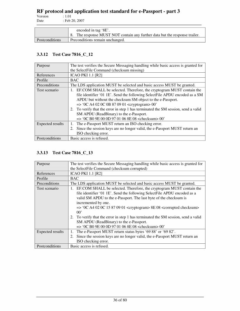
RF protocol and application test standard for e-Passport - part 3 Version : 1.01
Date : Feb 20, 2007
36 of 80
encoded in tag ‘8E’.
8. The response MUST NOT contain any further data but the response trailer.
Postconditions Preconditions remain unchanged.
3.3.12 Test Case 7816_C_12
Purpose The test verifies the Secure Messaging handling while basic access is granted for
the SelectFile Command (checksum missing)
References ICAO PKI 1.1 [R2]
Profile BAC
Preconditions The LDS application MUST be selected and basic access MUST be granted.
Test scenario 1. EF.COM SHALL be selected. Therefore, the cryptogram MUST contain the
file identifier ‘01 1E’. Send the following SelectFile APDU encoded as a SM
APDU but without the checksum SM object to the e-Passport.
=> ‘0C A4 02 0C 0B 87 09 01 <cryptogram> 00’
2. To verify that the error in step 1 has terminated the SM session, send a valid
SM APDU (ReadBinary) to the e-Passport.
=> ‘0C B0 9E 00 0D 97 01 06 8E 08 <checksum> 00’
Expected results 1. The e-Passport MUST return an ISO checking error.
2. Since the session keys are no longer valid, the e-Passport MUST return an
ISO checking error.
Postconditions Basic access is refused.
3.3.13 Test Case 7816_C_13
Purpose The test verifies the Secure Messaging handling while basic access is granted for
the SelectFile Command (checksum corrupted)
References ICAO PKI 1.1 [R2]
Profile BAC
Preconditions The LDS application MUST be selected and basic access MUST be granted.
Test scenario 1. EF.COM SHALL be selected. Therefore, the cryptogram MUST contain the
file identifier ‘01 1E’. Send the following SelectFile APDU encoded as a
valid SM APDU to the e-Passport. The last byte of the checksum is
incremented by one.
=> ‘0C A4 02 0C 15 87 09 01 <cryptogram> 8E 08 <corrupted checksum>
00’
2. To verify that the error in step 1 has terminated the SM session, send a valid
SM APDU (ReadBinary) to the e-Passport.
=> ‘0C B0 9E 00 0D 97 01 06 8E 08 <checksum> 00’
Expected results 1. The e-Passport MUST return status bytes ‘69 88’ or ‘69 82’.
2. Since the session keys are no longer valid, the e-Passport MUST return an
ISO checking error.
Postconditions Basic access is refused.
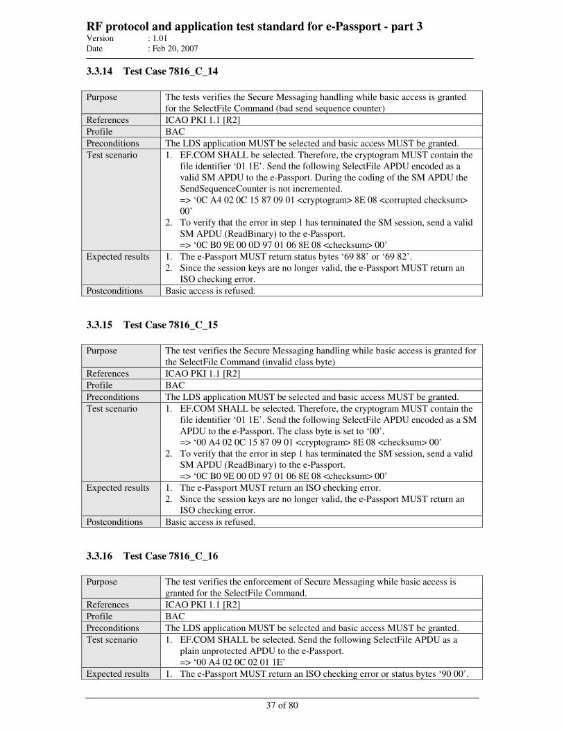
RF protocol and application test standard for e-Passport - part 3 Version : 1.01
Date : Feb 20, 2007
37 of 80
3.3.14 Test Case 7816_C_14
Purpose The tests verifies the Secure Messaging handling while basic access is granted
for the SelectFile Command (bad send sequence counter)
References ICAO PKI 1.1 [R2]
Profile BAC
Preconditions The LDS application MUST be selected and basic access MUST be granted.
Test scenario 1. EF.COM SHALL be selected. Therefore, the cryptogram MUST contain the
file identifier ‘01 1E’. Send the following SelectFile APDU encoded as a
valid SM APDU to the e-Passport. During the coding of the SM APDU the
SendSequenceCounter is not incremented.
=> ‘0C A4 02 0C 15 87 09 01 <cryptogram> 8E 08 <corrupted checksum>
00’
2. To verify that the error in step 1 has terminated the SM session, send a valid
SM APDU (ReadBinary) to the e-Passport.
=> ‘0C B0 9E 00 0D 97 01 06 8E 08 <checksum> 00’
Expected results 1. The e-Passport MUST return status bytes ‘69 88’ or ‘69 82’.
2. Since the session keys are no longer valid, the e-Passport MUST return an
ISO checking error.
Postconditions Basic access is refused.
3.3.15 Test Case 7816_C_15
Purpose The test verifies the Secure Messaging handling while basic access is granted for
the SelectFile Command (invalid class byte)
References ICAO PKI 1.1 [R2]
Profile BAC
Preconditions The LDS application MUST be selected and basic access MUST be granted.
Test scenario 1. EF.COM SHALL be selected. Therefore, the cryptogram MUST contain the
file identifier ‘01 1E’. Send the following SelectFile APDU encoded as a SM
APDU to the e-Passport. The class byte is set to ‘00’.
=> ‘00 A4 02 0C 15 87 09 01 <cryptogram> 8E 08 <checksum> 00’
2. To verify that the error in step 1 has terminated the SM session, send a valid
SM APDU (ReadBinary) to the e-Passport.
=> ‘0C B0 9E 00 0D 97 01 06 8E 08 <checksum> 00’
Expected results 1. The e-Passport MUST return an ISO checking error.
2. Since the session keys are no longer valid, the e-Passport MUST return an
ISO checking error.
Postconditions Basic access is refused.
3.3.16 Test Case 7816_C_16
Purpose The test verifies the enforcement of Secure Messaging while basic access is
granted for the SelectFile Command.
References ICAO PKI 1.1 [R2]
Profile BAC
Preconditions The LDS application MUST be selected and basic access MUST be granted.
Test scenario 1. EF.COM SHALL be selected. Send the following SelectFile APDU as a
plain unprotected APDU to the e-Passport.
=> ‘00 A4 02 0C 02 01 1E’
Expected results 1. The e-Passport MUST return an ISO checking error or status bytes ‘90 00’.
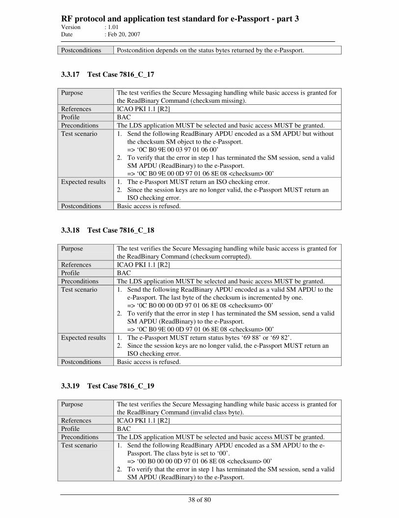
RF protocol and application test standard for e-Passport - part 3 Version : 1.01
Date : Feb 20, 2007
38 of 80
Postconditions Postcondition depends on the status bytes returned by the e-Passport.
3.3.17 Test Case 7816_C_17
Purpose The test verifies the Secure Messaging handling while basic access is granted for
the ReadBinary Command (checksum missing).
References ICAO PKI 1.1 [R2]
Profile BAC
Preconditions The LDS application MUST be selected and basic access MUST be granted.
Test scenario 1. Send the following ReadBinary APDU encoded as a SM APDU but without
the checksum SM object to the e-Passport.
=> ‘0C B0 9E 00 03 97 01 06 00’
2. To verify that the error in step 1 has terminated the SM session, send a valid
SM APDU (ReadBinary) to the e-Passport.
=> ‘0C B0 9E 00 0D 97 01 06 8E 08 <checksum> 00’
Expected results 1. The e-Passport MUST return an ISO checking error.
2. Since the session keys are no longer valid, the e-Passport MUST return an
ISO checking error.
Postconditions Basic access is refused.
3.3.18 Test Case 7816_C_18
Purpose The test verifies the Secure Messaging handling while basic access is granted for
the ReadBinary Command (checksum corrupted).
References ICAO PKI 1.1 [R2]
Profile BAC
Preconditions The LDS application MUST be selected and basic access MUST be granted.
Test scenario 1. Send the following ReadBinary APDU encoded as a valid SM APDU to the
e-Passport. The last byte of the checksum is incremented by one.
=> ‘0C B0 00 00 0D 97 01 06 8E 08 <checksum> 00’
2. To verify that the error in step 1 has terminated the SM session, send a valid
SM APDU (ReadBinary) to the e-Passport.
=> ‘0C B0 9E 00 0D 97 01 06 8E 08 <checksum> 00’
Expected results 1. The e-Passport MUST return status bytes ‘69 88’ or ‘69 82’.
2. Since the session keys are no longer valid, the e-Passport MUST return an
ISO checking error.
Postconditions Basic access is refused.
3.3.19 Test Case 7816_C_19
Purpose The test verifies the Secure Messaging handling while basic access is granted for
the ReadBinary Command (invalid class byte).
References ICAO PKI 1.1 [R2]
Profile BAC
Preconditions The LDS application MUST be selected and basic access MUST be granted.
Test scenario 1. Send the following ReadBinary APDU encoded as a SM APDU to the e-
Passport. The class byte is set to ‘00’.
=> ‘00 B0 00 00 0D 97 01 06 8E 08 <checksum> 00’
2. To verify that the error in step 1 has terminated the SM session, send a valid
SM APDU (ReadBinary) to the e-Passport.
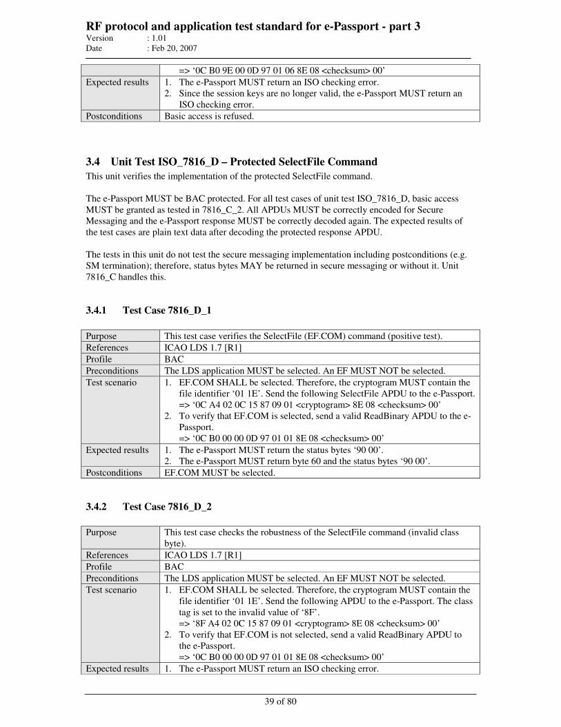
RF protocol and application test standard for e-Passport - part 3 Version : 1.01
Date : Feb 20, 2007
39 of 80
=> ‘0C B0 9E 00 0D 97 01 06 8E 08 <checksum> 00’
Expected results 1. The e-Passport MUST return an ISO checking error.
2. Since the session keys are no longer valid, the e-Passport MUST return an
ISO checking error.
Postconditions Basic access is refused.
3.4 Unit Test ISO_7816_D – Protected SelectFile Command
This unit verifies the implementation of the protected SelectFile command.
The e-Passport MUST be BAC protected. For all test cases of unit test ISO_7816_D, basic access
MUST be granted as tested in 7816_C_2. All APDUs MUST be correctly encoded for Secure
Messaging and the e-Passport response MUST be correctly decoded again. The expected results of
the test cases are plain text data after decoding the protected response APDU.
The tests in this unit do not test the secure messaging implementation including postconditions (e.g.
SM termination); therefore, status bytes MAY be returned in secure messaging or without it. Unit
7816_C handles this.
3.4.1 Test Case 7816_D_1
Purpose This test case verifies the SelectFile (EF.COM) command (positive test).
References ICAO LDS 1.7 [R1]
Profile BAC
Preconditions The LDS application MUST be selected. An EF MUST NOT be selected.
Test scenario 1. EF.COM SHALL be selected. Therefore, the cryptogram MUST contain the
file identifier ‘01 1E’. Send the following SelectFile APDU to the e-Passport.
=> ‘0C A4 02 0C 15 87 09 01 <cryptogram> 8E 08 <checksum> 00’
2. To verify that EF.COM is selected, send a valid ReadBinary APDU to the e-
Passport.
=> ‘0C B0 00 00 0D 97 01 01 8E 08 <checksum> 00’
Expected results 1. The e-Passport MUST return the status bytes ‘90 00’.
2. The e-Passport MUST return byte 60 and the status bytes ‘90 00’.
Postconditions EF.COM MUST be selected.
3.4.2 Test Case 7816_D_2
Purpose This test case checks the robustness of the SelectFile command (invalid class
byte).
References ICAO LDS 1.7 [R1]
Profile BAC
Preconditions The LDS application MUST be selected. An EF MUST NOT be selected.
Test scenario 1. EF.COM SHALL be selected. Therefore, the cryptogram MUST contain the
file identifier ‘01 1E’. Send the following APDU to the e-Passport. The class
tag is set to the invalid value of ‘8F’.
=> ‘8F A4 02 0C 15 87 09 01 <cryptogram> 8E 08 <checksum> 00’
2. To verify that EF.COM is not selected, send a valid ReadBinary APDU to
the e-Passport.
=> ‘0C B0 00 00 0D 97 01 01 8E 08 <checksum> 00’
Expected results 1. The e-Passport MUST return an ISO checking error.
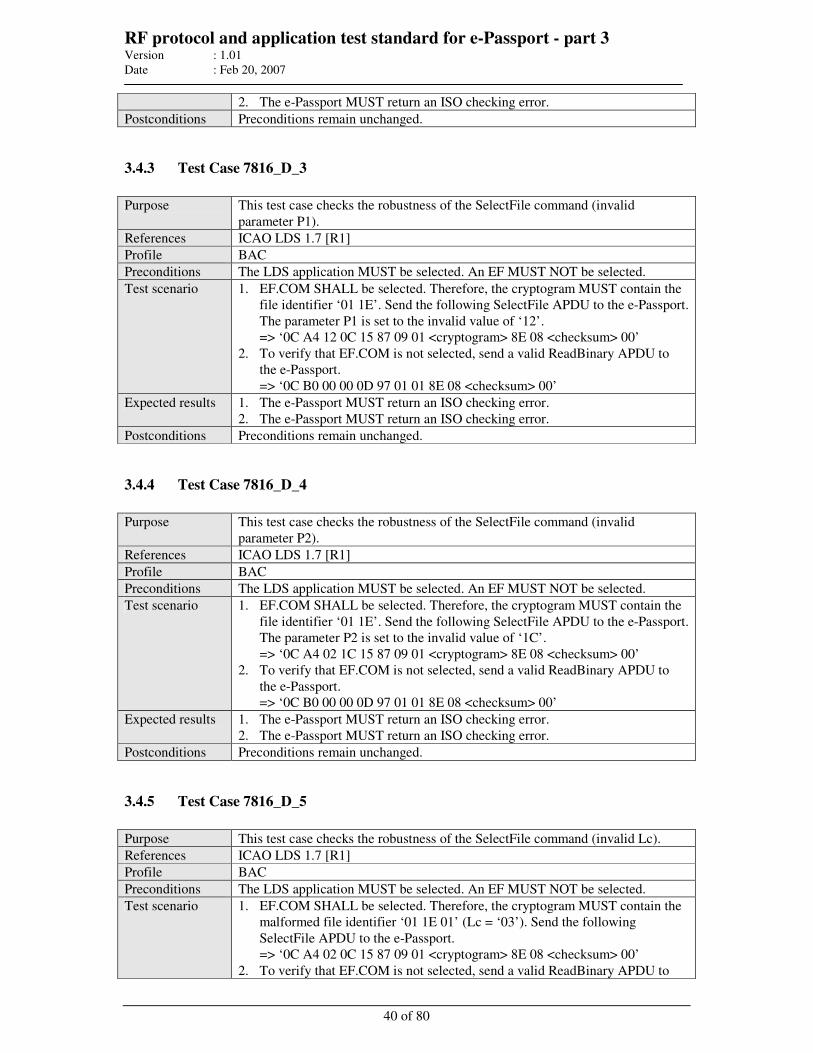
RF protocol and application test standard for e-Passport - part 3 Version : 1.01
Date : Feb 20, 2007
40 of 80
2. The e-Passport MUST return an ISO checking error.
Postconditions Preconditions remain unchanged.
3.4.3 Test Case 7816_D_3
Purpose This test case checks the robustness of the SelectFile command (invalid
parameter P1).
References ICAO LDS 1.7 [R1]
Profile BAC
Preconditions The LDS application MUST be selected. An EF MUST NOT be selected.
Test scenario 1. EF.COM SHALL be selected. Therefore, the cryptogram MUST contain the
file identifier ‘01 1E’. Send the following SelectFile APDU to the e-Passport.
The parameter P1 is set to the invalid value of ‘12’.
=> ‘0C A4 12 0C 15 87 09 01 <cryptogram> 8E 08 <checksum> 00’
2. To verify that EF.COM is not selected, send a valid ReadBinary APDU to
the e-Passport.
=> ‘0C B0 00 00 0D 97 01 01 8E 08 <checksum> 00’
Expected results 1. The e-Passport MUST return an ISO checking error.
2. The e-Passport MUST return an ISO checking error.
Postconditions Preconditions remain unchanged.
3.4.4 Test Case 7816_D_4
Purpose This test case checks the robustness of the SelectFile command (invalid
parameter P2).
References ICAO LDS 1.7 [R1]
Profile BAC
Preconditions The LDS application MUST be selected. An EF MUST NOT be selected.
Test scenario 1. EF.COM SHALL be selected. Therefore, the cryptogram MUST contain the
file identifier ‘01 1E’. Send the following SelectFile APDU to the e-Passport.
The parameter P2 is set to the invalid value of ‘1C’.
=> ‘0C A4 02 1C 15 87 09 01 <cryptogram> 8E 08 <checksum> 00’
2. To verify that EF.COM is not selected, send a valid ReadBinary APDU to
the e-Passport.
=> ‘0C B0 00 00 0D 97 01 01 8E 08 <checksum> 00’
Expected results 1. The e-Passport MUST return an ISO checking error.
2. The e-Passport MUST return an ISO checking error.
Postconditions Preconditions remain unchanged.
3.4.5 Test Case 7816_D_5
Purpose This test case checks the robustness of the SelectFile command (invalid Lc).
References ICAO LDS 1.7 [R1]
Profile BAC
Preconditions The LDS application MUST be selected. An EF MUST NOT be selected.
Test scenario 1. EF.COM SHALL be selected. Therefore, the cryptogram MUST contain the
malformed file identifier ‘01 1E 01’ (Lc = ‘03’). Send the following
SelectFile APDU to the e-Passport.
=> ‘0C A4 02 0C 15 87 09 01 <cryptogram> 8E 08 <checksum> 00’
2. To verify that EF.COM is not selected, send a valid ReadBinary APDU to
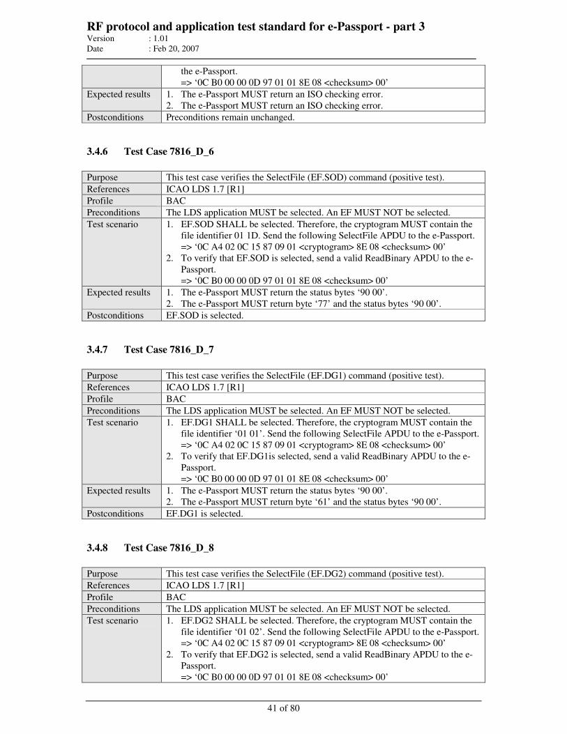
RF protocol and application test standard for e-Passport - part 3 Version : 1.01
Date : Feb 20, 2007
41 of 80
the e-Passport.
=> ‘0C B0 00 00 0D 97 01 01 8E 08 <checksum> 00’
Expected results 1. The e-Passport MUST return an ISO checking error.
2. The e-Passport MUST return an ISO checking error.
Postconditions Preconditions remain unchanged.
3.4.6 Test Case 7816_D_6
Purpose This test case verifies the SelectFile (EF.SOD) command (positive test).
References ICAO LDS 1.7 [R1]
Profile BAC
Preconditions The LDS application MUST be selected. An EF MUST NOT be selected.
Test scenario 1. EF.SOD SHALL be selected. Therefore, the cryptogram MUST contain the
file identifier 01 1D. Send the following SelectFile APDU to the e-Passport.
=> ‘0C A4 02 0C 15 87 09 01 <cryptogram> 8E 08 <checksum> 00’
2. To verify that EF.SOD is selected, send a valid ReadBinary APDU to the e-
Passport.
=> ‘0C B0 00 00 0D 97 01 01 8E 08 <checksum> 00’
Expected results 1. The e-Passport MUST return the status bytes ‘90 00’.
2. The e-Passport MUST return byte ‘77’ and the status bytes ‘90 00’.
Postconditions EF.SOD is selected.
3.4.7 Test Case 7816_D_7
Purpose This test case verifies the SelectFile (EF.DG1) command (positive test).
References ICAO LDS 1.7 [R1]
Profile BAC
Preconditions The LDS application MUST be selected. An EF MUST NOT be selected.
Test scenario 1. EF.DG1 SHALL be selected. Therefore, the cryptogram MUST contain the
file identifier ‘01 01’. Send the following SelectFile APDU to the e-Passport.
=> ‘0C A4 02 0C 15 87 09 01 <cryptogram> 8E 08 <checksum> 00’
2. To verify that EF.DG1is selected, send a valid ReadBinary APDU to the e-
Passport.
=> ‘0C B0 00 00 0D 97 01 01 8E 08 <checksum> 00’
Expected results 1. The e-Passport MUST return the status bytes ‘90 00’.
2. The e-Passport MUST return byte ‘61’ and the status bytes ‘90 00’.
Postconditions EF.DG1 is selected.
3.4.8 Test Case 7816_D_8
Purpose This test case verifies the SelectFile (EF.DG2) command (positive test).
References ICAO LDS 1.7 [R1]
Profile BAC
Preconditions The LDS application MUST be selected. An EF MUST NOT be selected.
Test scenario 1. EF.DG2 SHALL be selected. Therefore, the cryptogram MUST contain the
file identifier ‘01 02’. Send the following SelectFile APDU to the e-Passport.
=> ‘0C A4 02 0C 15 87 09 01 <cryptogram> 8E 08 <checksum> 00’
2. To verify that EF.DG2 is selected, send a valid ReadBinary APDU to the e-
Passport.
=> ‘0C B0 00 00 0D 97 01 01 8E 08 <checksum> 00’
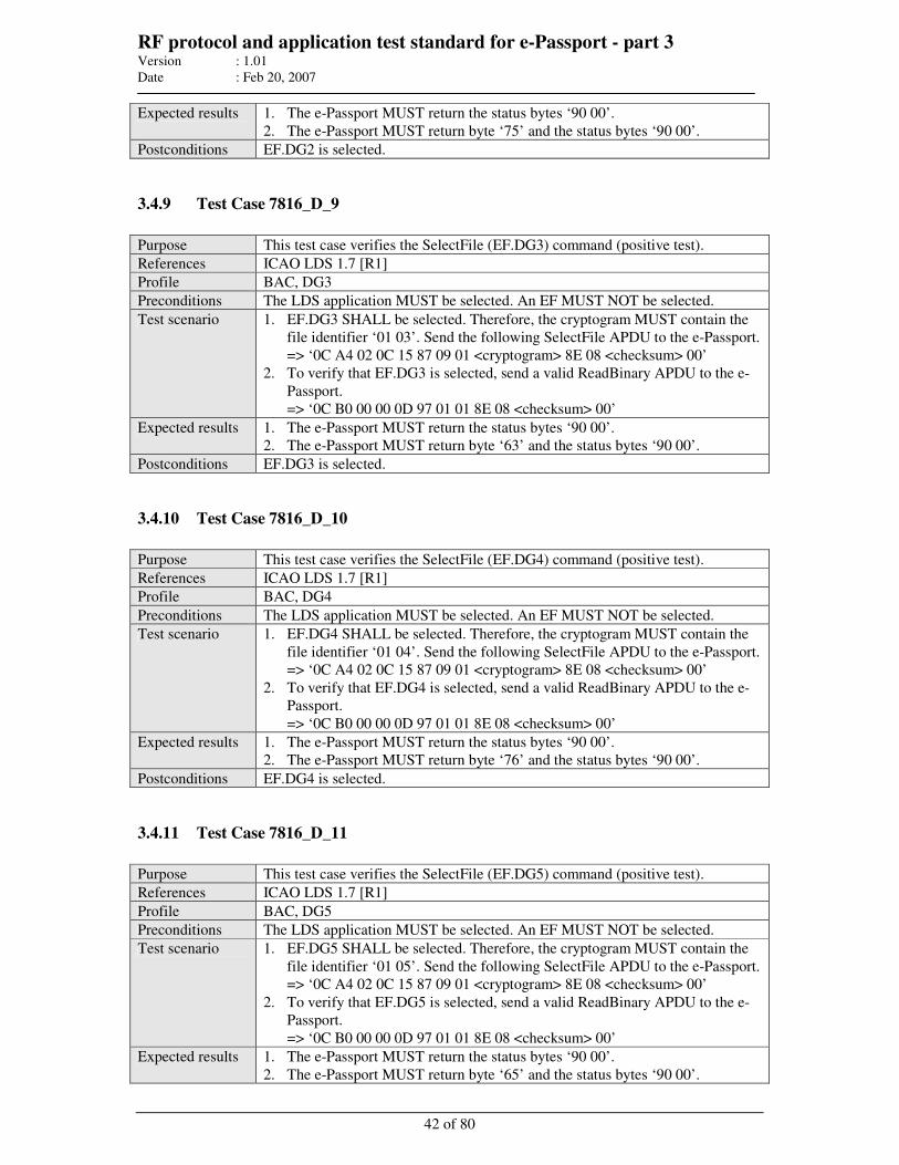
RF protocol and application test standard for e-Passport - part 3 Version : 1.01
Date : Feb 20, 2007
42 of 80
Expected results 1. The e-Passport MUST return the status bytes ‘90 00’.
2. The e-Passport MUST return byte ‘75’ and the status bytes ‘90 00’.
Postconditions EF.DG2 is selected.
3.4.9 Test Case 7816_D_9
Purpose This test case verifies the SelectFile (EF.DG3) command (positive test).
References ICAO LDS 1.7 [R1]
Profile BAC, DG3
Preconditions The LDS application MUST be selected. An EF MUST NOT be selected.
Test scenario 1. EF.DG3 SHALL be selected. Therefore, the cryptogram MUST contain the
file identifier ‘01 03’. Send the following SelectFile APDU to the e-Passport.
=> ‘0C A4 02 0C 15 87 09 01 <cryptogram> 8E 08 <checksum> 00’
2. To verify that EF.DG3 is selected, send a valid ReadBinary APDU to the e-
Passport.
=> ‘0C B0 00 00 0D 97 01 01 8E 08 <checksum> 00’
Expected results 1. The e-Passport MUST return the status bytes ‘90 00’.
2. The e-Passport MUST return byte ‘63’ and the status bytes ‘90 00’.
Postconditions EF.DG3 is selected.
3.4.10 Test Case 7816_D_10
Purpose This test case verifies the SelectFile (EF.DG4) command (positive test).
References ICAO LDS 1.7 [R1]
Profile BAC, DG4
Preconditions The LDS application MUST be selected. An EF MUST NOT be selected.
Test scenario 1. EF.DG4 SHALL be selected. Therefore, the cryptogram MUST contain the
file identifier ‘01 04’. Send the following SelectFile APDU to the e-Passport.
=> ‘0C A4 02 0C 15 87 09 01 <cryptogram> 8E 08 <checksum> 00’
2. To verify that EF.DG4 is selected, send a valid ReadBinary APDU to the e-
Passport.
=> ‘0C B0 00 00 0D 97 01 01 8E 08 <checksum> 00’
Expected results 1. The e-Passport MUST return the status bytes ‘90 00’.
2. The e-Passport MUST return byte ‘76’ and the status bytes ‘90 00’.
Postconditions EF.DG4 is selected.
3.4.11 Test Case 7816_D_11
Purpose This test case verifies the SelectFile (EF.DG5) command (positive test).
References ICAO LDS 1.7 [R1]
Profile BAC, DG5
Preconditions The LDS application MUST be selected. An EF MUST NOT be selected.
Test scenario 1. EF.DG5 SHALL be selected. Therefore, the cryptogram MUST contain the
file identifier ‘01 05’. Send the following SelectFile APDU to the e-Passport.
=> ‘0C A4 02 0C 15 87 09 01 <cryptogram> 8E 08 <checksum> 00’
2. To verify that EF.DG5 is selected, send a valid ReadBinary APDU to the e-
Passport.
=> ‘0C B0 00 00 0D 97 01 01 8E 08 <checksum> 00’
Expected results 1. The e-Passport MUST return the status bytes ‘90 00’.
2. The e-Passport MUST return byte ‘65’ and the status bytes ‘90 00’.
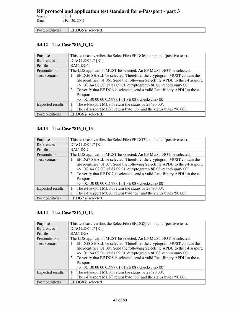
RF protocol and application test standard for e-Passport - part 3 Version : 1.01
Date : Feb 20, 2007
43 of 80
Postconditions EF.DG5 is selected.
3.4.12 Test Case 7816_D_12
Purpose This test case verifies the SelectFile (EF.DG6) command (positive test).
References ICAO LDS 1.7 [R1]
Profile BAC, DG6
Preconditions The LDS application MUST be selected. An EF MUST NOT be selected.
Test scenario 1. EF.DG6 SHALL be selected. Therefore, the cryptogram MUST contain the
file identifier ‘01 06’. Send the following SelectFile APDU to the e-Passport.
=> ‘0C A4 02 0C 15 87 09 01 <cryptogram> 8E 08 <checksum> 00’
2. To verify that EF.DG6 is selected, send a valid ReadBinary APDU to the e-
Passport.
=> ‘0C B0 00 00 0D 97 01 01 8E 08 <checksum> 00’
Expected results 1. The e-Passport MUST return the status bytes ‘90 00’.
2. The e-Passport MUST return byte ‘66’ and the status bytes ‘90 00’.
Postconditions EF.DG6 is selected.
3.4.13 Test Case 7816_D_13
Purpose This test case verifies the SelectFile (EF.DG7) command (positive test).
References ICAO LDS 1.7 [R1]
Profile BAC, DG7
Preconditions The LDS application MUST be selected. An EF MUST NOT be selected.
Test scenario 1. EF.DG7 SHALL be selected. Therefore, the cryptogram MUST contain the
file identifier ‘01 07’. Send the following SelectFile APDU to the e-Passport.
=> ‘0C A4 02 0C 15 87 09 01 <cryptogram> 8E 08 <checksum> 00’
2. To verify that EF.DG7 is selected, send a valid ReadBinary APDU to the e-
Passport.
=> ‘0C B0 00 00 0D 97 01 01 8E 08 <checksum> 00’
Expected results 1. The e-Passport MUST return the status bytes ‘90 00’.
2. The e-Passport MUST return byte ‘67’ and the status bytes ‘90 00’.
Postconditions EF.DG7 is selected.
3.4.14 Test Case 7816_D_14
Purpose This test case verifies the SelectFile (EF.DG8) command (positive test).
References ICAO LDS 1.7 [R1]
Profile BAC, DG8
Preconditions The LDS application MUST be selected. An EF MUST NOT be selected.
Test scenario 1. EF.DG8 SHALL be selected. Therefore, the cryptogram MUST contain the
file identifier ‘01 08’. Send the following SelectFile APDU to the e-Passport.
=> ‘0C A4 02 0C 15 87 09 01 <cryptogram> 8E 08 <checksum> 00’
2. To verify that EF.DG8 is selected, send a valid ReadBinary APDU to the e-
Passport.
=> ‘0C B0 00 00 0D 97 01 01 8E 08 <checksum> 00’
Expected results 1. The e-Passport MUST return the status bytes ‘90 00’.
2. The e-Passport MUST return byte ‘68’ and the status bytes ‘90 00’.
Postconditions EF.DG8 is selected.
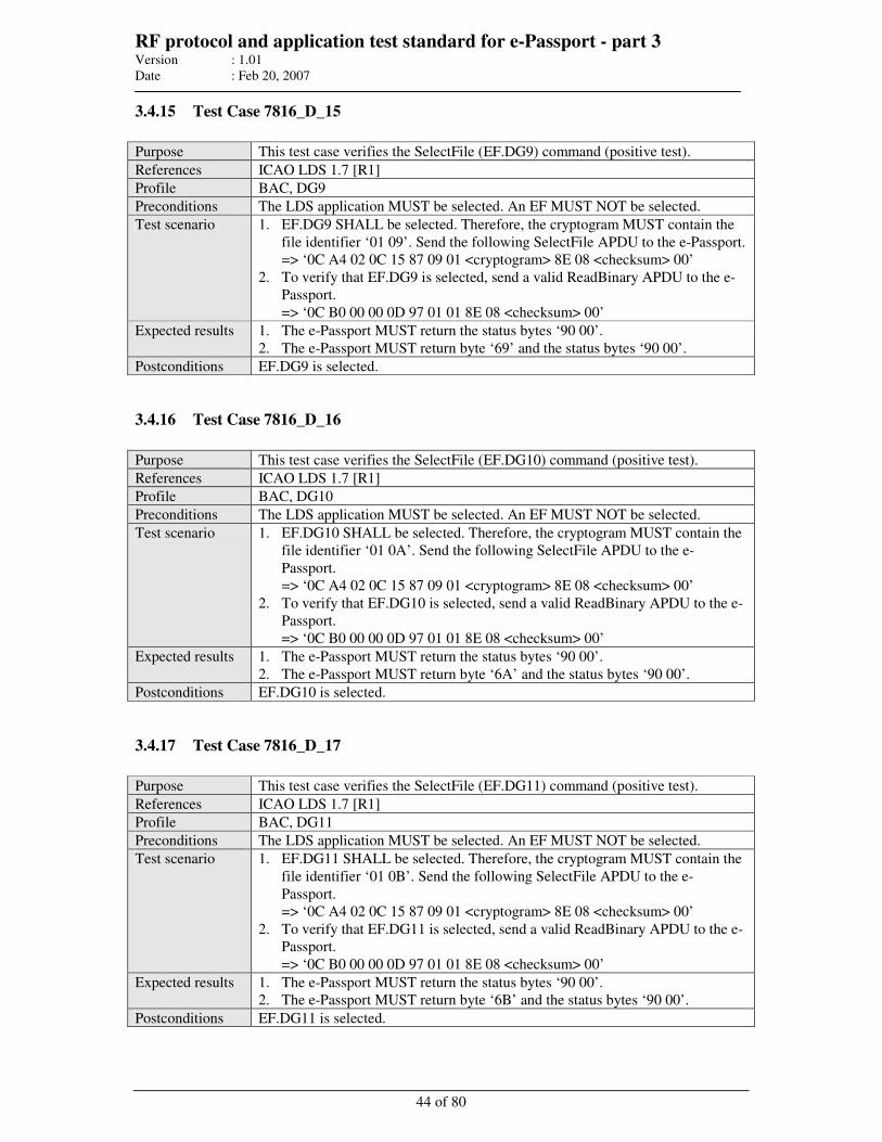
RF protocol and application test standard for e-Passport - part 3 Version : 1.01
Date : Feb 20, 2007
44 of 80
3.4.15 Test Case 7816_D_15
Purpose This test case verifies the SelectFile (EF.DG9) command (positive test).
References ICAO LDS 1.7 [R1]
Profile BAC, DG9
Preconditions The LDS application MUST be selected. An EF MUST NOT be selected.
Test scenario 1. EF.DG9 SHALL be selected. Therefore, the cryptogram MUST contain the
file identifier ‘01 09’. Send the following SelectFile APDU to the e-Passport.
=> ‘0C A4 02 0C 15 87 09 01 <cryptogram> 8E 08 <checksum> 00’
2. To verify that EF.DG9 is selected, send a valid ReadBinary APDU to the e-
Passport.
=> ‘0C B0 00 00 0D 97 01 01 8E 08 <checksum> 00’
Expected results 1. The e-Passport MUST return the status bytes ‘90 00’.
2. The e-Passport MUST return byte ‘69’ and the status bytes ‘90 00’.
Postconditions EF.DG9 is selected.
3.4.16 Test Case 7816_D_16
Purpose This test case verifies the SelectFile (EF.DG10) command (positive test).
References ICAO LDS 1.7 [R1]
Profile BAC, DG10
Preconditions The LDS application MUST be selected. An EF MUST NOT be selected.
Test scenario 1. EF.DG10 SHALL be selected. Therefore, the cryptogram MUST contain the
file identifier ‘01 0A’. Send the following SelectFile APDU to the e-
Passport.
=> ‘0C A4 02 0C 15 87 09 01 <cryptogram> 8E 08 <checksum> 00’
2. To verify that EF.DG10 is selected, send a valid ReadBinary APDU to the e-
Passport.
=> ‘0C B0 00 00 0D 97 01 01 8E 08 <checksum> 00’
Expected results 1. The e-Passport MUST return the status bytes ‘90 00’.
2. The e-Passport MUST return byte ‘6A’ and the status bytes ‘90 00’.
Postconditions EF.DG10 is selected.
3.4.17 Test Case 7816_D_17
Purpose This test case verifies the SelectFile (EF.DG11) command (positive test).
References ICAO LDS 1.7 [R1]
Profile BAC, DG11
Preconditions The LDS application MUST be selected. An EF MUST NOT be selected.
Test scenario 1. EF.DG11 SHALL be selected. Therefore, the cryptogram MUST contain the
file identifier ‘01 0B’. Send the following SelectFile APDU to the e-
Passport.
=> ‘0C A4 02 0C 15 87 09 01 <cryptogram> 8E 08 <checksum> 00’
2. To verify that EF.DG11 is selected, send a valid ReadBinary APDU to the e-
Passport.
=> ‘0C B0 00 00 0D 97 01 01 8E 08 <checksum> 00’
Expected results 1. The e-Passport MUST return the status bytes ‘90 00’.
2. The e-Passport MUST return byte ‘6B’ and the status bytes ‘90 00’.
Postconditions EF.DG11 is selected.
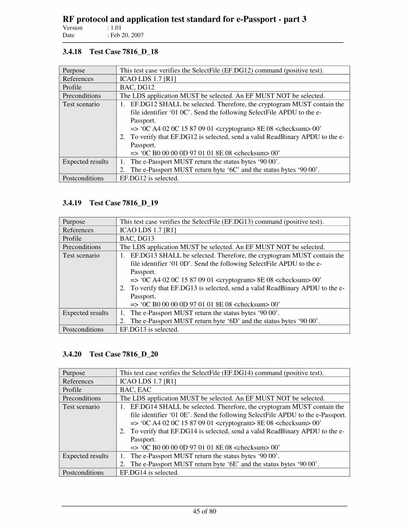
RF protocol and application test standard for e-Passport - part 3 Version : 1.01
Date : Feb 20, 2007
45 of 80
3.4.18 Test Case 7816_D_18
Purpose This test case verifies the SelectFile (EF.DG12) command (positive test).
References ICAO LDS 1.7 [R1]
Profile BAC, DG12
Preconditions The LDS application MUST be selected. An EF MUST NOT be selected.
Test scenario 1. EF.DG12 SHALL be selected. Therefore, the cryptogram MUST contain the
file identifier ‘01 0C’. Send the following SelectFile APDU to the e-
Passport.
=> ‘0C A4 02 0C 15 87 09 01 <cryptogram> 8E 08 <checksum> 00’
2. To verify that EF.DG12 is selected, send a valid ReadBinary APDU to the e-
Passport.
=> ‘0C B0 00 00 0D 97 01 01 8E 08 <checksum> 00’
Expected results 1. The e-Passport MUST return the status bytes ‘90 00’.
2. The e-Passport MUST return byte ‘6C’ and the status bytes ‘90 00’.
Postconditions EF.DG12 is selected.
3.4.19 Test Case 7816_D_19
Purpose This test case verifies the SelectFile (EF.DG13) command (positive test).
References ICAO LDS 1.7 [R1]
Profile BAC, DG13
Preconditions The LDS application MUST be selected. An EF MUST NOT be selected.
Test scenario 1. EF.DG13 SHALL be selected. Therefore, the cryptogram MUST contain the
file identifier ‘01 0D’. Send the following SelectFile APDU to the e-
Passport.
=> ‘0C A4 02 0C 15 87 09 01 <cryptogram> 8E 08 <checksum> 00’
2. To verify that EF.DG13 is selected, send a valid ReadBinary APDU to the e-
Passport.
=> ‘0C B0 00 00 0D 97 01 01 8E 08 <checksum> 00’
Expected results 1. The e-Passport MUST return the status bytes ‘90 00’.
2. The e-Passport MUST return byte ‘6D’ and the status bytes ‘90 00’.
Postconditions EF.DG13 is selected.
3.4.20 Test Case 7816_D_20
Purpose This test case verifies the SelectFile (EF.DG14) command (positive test).
References ICAO LDS 1.7 [R1]
Profile BAC, EAC
Preconditions The LDS application MUST be selected. An EF MUST NOT be selected.
Test scenario 1. EF.DG14 SHALL be selected. Therefore, the cryptogram MUST contain the
file identifier ‘01 0E’. Send the following SelectFile APDU to the e-Passport.
=> ‘0C A4 02 0C 15 87 09 01 <cryptogram> 8E 08 <checksum> 00’
2. To verify that EF.DG14 is selected, send a valid ReadBinary APDU to the e-
Passport.
=> ‘0C B0 00 00 0D 97 01 01 8E 08 <checksum> 00’
Expected results 1. The e-Passport MUST return the status bytes ‘90 00’.
2. The e-Passport MUST return byte ‘6E’ and the status bytes ‘90 00’.
Postconditions EF.DG14 is selected.
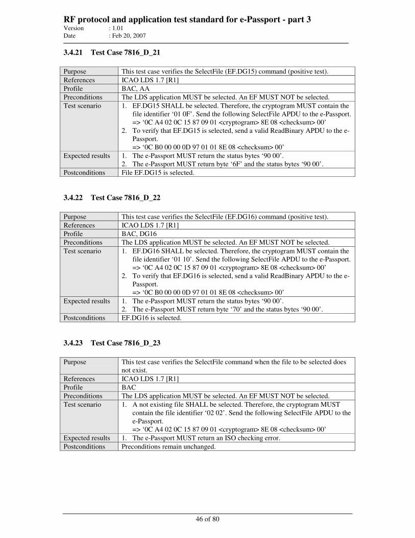
RF protocol and application test standard for e-Passport - part 3 Version : 1.01
Date : Feb 20, 2007
46 of 80
3.4.21 Test Case 7816_D_21
Purpose This test case verifies the SelectFile (EF.DG15) command (positive test).
References ICAO LDS 1.7 [R1]
Profile BAC, AA
Preconditions The LDS application MUST be selected. An EF MUST NOT be selected.
Test scenario 1. EF.DG15 SHALL be selected. Therefore, the cryptogram MUST contain the
file identifier ‘01 0F’. Send the following SelectFile APDU to the e-Passport.
=> ‘0C A4 02 0C 15 87 09 01 <cryptogram> 8E 08 <checksum> 00’
2. To verify that EF.DG15 is selected, send a valid ReadBinary APDU to the e-
Passport.
=> ‘0C B0 00 00 0D 97 01 01 8E 08 <checksum> 00’
Expected results 1. The e-Passport MUST return the status bytes ‘90 00’.
2. The e-Passport MUST return byte ‘6F’ and the status bytes ‘90 00’.
Postconditions File EF.DG15 is selected.
3.4.22 Test Case 7816_D_22
Purpose This test case verifies the SelectFile (EF.DG16) command (positive test).
References ICAO LDS 1.7 [R1]
Profile BAC, DG16
Preconditions The LDS application MUST be selected. An EF MUST NOT be selected.
Test scenario 1. EF.DG16 SHALL be selected. Therefore, the cryptogram MUST contain the
file identifier ‘01 10’. Send the following SelectFile APDU to the e-Passport.
=> ‘0C A4 02 0C 15 87 09 01 <cryptogram> 8E 08 <checksum> 00’
2. To verify that EF.DG16 is selected, send a valid ReadBinary APDU to the e-
Passport.
=> ‘0C B0 00 00 0D 97 01 01 8E 08 <checksum> 00’
Expected results 1. The e-Passport MUST return the status bytes ‘90 00’.
2. The e-Passport MUST return byte ‘70’ and the status bytes ‘90 00’.
Postconditions EF.DG16 is selected.
3.4.23 Test Case 7816_D_23
Purpose This test case verifies the SelectFile command when the file to be selected does
not exist.
References ICAO LDS 1.7 [R1]
Profile BAC
Preconditions The LDS application MUST be selected. An EF MUST NOT be selected.
Test scenario 1. A not existing file SHALL be selected. Therefore, the cryptogram MUST
contain the file identifier ‘02 02’. Send the following SelectFile APDU to the
e-Passport.
=> ‘0C A4 02 0C 15 87 09 01 <cryptogram> 8E 08 <checksum> 00’
Expected results 1. The e-Passport MUST return an ISO checking error.
Postconditions Preconditions remain unchanged.
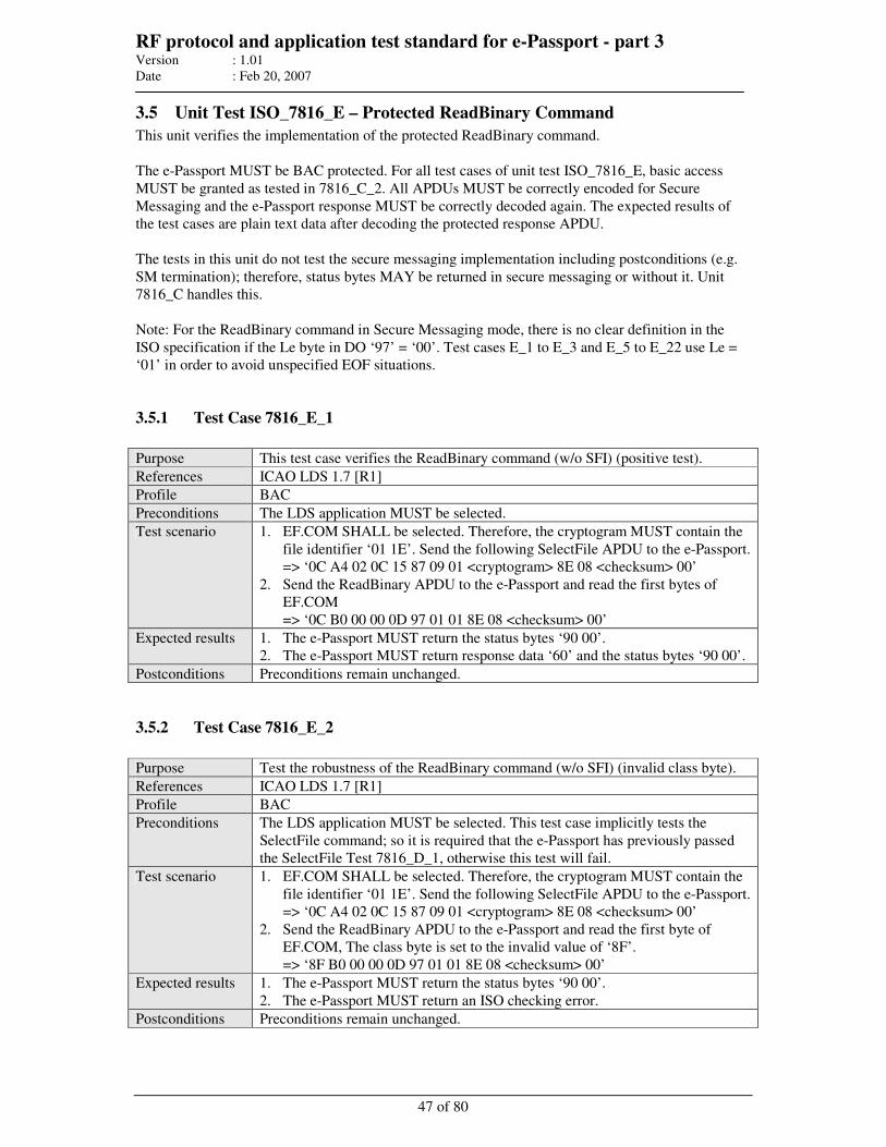
RF protocol and application test standard for e-Passport - part 3 Version : 1.01
Date : Feb 20, 2007
47 of 80
3.5 Unit Test ISO_7816_E – Protected ReadBinary Command
This unit verifies the implementation of the protected ReadBinary command.
The e-Passport MUST be BAC protected. For all test cases of unit test ISO_7816_E, basic access
MUST be granted as tested in 7816_C_2. All APDUs MUST be correctly encoded for Secure
Messaging and the e-Passport response MUST be correctly decoded again. The expected results of
the test cases are plain text data after decoding the protected response APDU.
The tests in this unit do not test the secure messaging implementation including postconditions (e.g.
SM termination); therefore, status bytes MAY be returned in secure messaging or without it. Unit
7816_C handles this.
Note: For the ReadBinary command in Secure Messaging mode, there is no clear definition in the
ISO specification if the Le byte in DO ‘97’ = ‘00’. Test cases E_1 to E_3 and E_5 to E_22 use Le =
‘01’ in order to avoid unspecified EOF situations.
3.5.1 Test Case 7816_E_1
Purpose This test case verifies the ReadBinary command (w/o SFI) (positive test).
References ICAO LDS 1.7 [R1]
Profile BAC
Preconditions The LDS application MUST be selected.
Test scenario 1. EF.COM SHALL be selected. Therefore, the cryptogram MUST contain the
file identifier ‘01 1E’. Send the following SelectFile APDU to the e-Passport.
=> ‘0C A4 02 0C 15 87 09 01 <cryptogram> 8E 08 <checksum> 00’
2. Send the ReadBinary APDU to the e-Passport and read the first bytes of
EF.COM
=> ‘0C B0 00 00 0D 97 01 01 8E 08 <checksum> 00’
Expected results 1. The e-Passport MUST return the status bytes ‘90 00’.
2. The e-Passport MUST return response data ‘60’ and the status bytes ‘90 00’.
Postconditions Preconditions remain unchanged.
3.5.2 Test Case 7816_E_2
Purpose Test the robustness of the ReadBinary command (w/o SFI) (invalid class byte).
References ICAO LDS 1.7 [R1]
Profile BAC
Preconditions The LDS application MUST be selected. This test case implicitly tests the
SelectFile command; so it is required that the e-Passport has previously passed
the SelectFile Test 7816_D_1, otherwise this test will fail.
Test scenario 1. EF.COM SHALL be selected. Therefore, the cryptogram MUST contain the
file identifier ‘01 1E’. Send the following SelectFile APDU to the e-Passport.
=> ‘0C A4 02 0C 15 87 09 01 <cryptogram> 8E 08 <checksum> 00’
2. Send the ReadBinary APDU to the e-Passport and read the first byte of
EF.COM, The class byte is set to the invalid value of ‘8F’.
=> ‘8F B0 00 00 0D 97 01 01 8E 08 <checksum> 00’
Expected results 1. The e-Passport MUST return the status bytes ‘90 00’.
2. The e-Passport MUST return an ISO checking error.
Postconditions Preconditions remain unchanged.
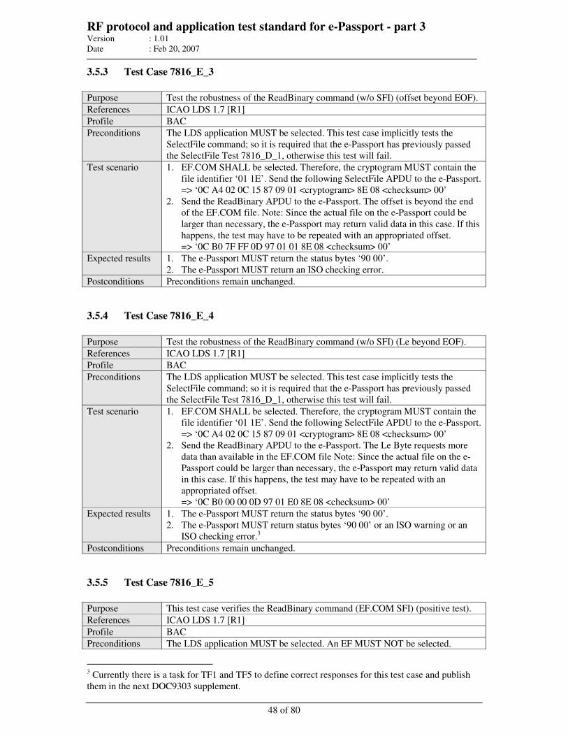
RF protocol and application test standard for e-Passport - part 3 Version : 1.01
Date : Feb 20, 2007
48 of 80
3.5.3 Test Case 7816_E_3
Purpose Test the robustness of the ReadBinary command (w/o SFI) (offset beyond EOF).
References ICAO LDS 1.7 [R1]
Profile BAC
Preconditions The LDS application MUST be selected. This test case implicitly tests the
SelectFile command; so it is required that the e-Passport has previously passed
the SelectFile Test 7816_D_1, otherwise this test will fail.
Test scenario 1. EF.COM SHALL be selected. Therefore, the cryptogram MUST contain the
file identifier ‘01 1E’. Send the following SelectFile APDU to the e-Passport.
=> ‘0C A4 02 0C 15 87 09 01 <cryptogram> 8E 08 <checksum> 00’
2. Send the ReadBinary APDU to the e-Passport. The offset is beyond the end
of the EF.COM file. Note: Since the actual file on the e-Passport could be
larger than necessary, the e-Passport may return valid data in this case. If this
happens, the test may have to be repeated with an appropriated offset.
=> ‘0C B0 7F FF 0D 97 01 01 8E 08 <checksum> 00’
Expected results 1. The e-Passport MUST return the status bytes ‘90 00’.
2. The e-Passport MUST return an ISO checking error.
Postconditions Preconditions remain unchanged.
3.5.4 Test Case 7816_E_4
Purpose Test the robustness of the ReadBinary command (w/o SFI) (Le beyond EOF).
References ICAO LDS 1.7 [R1]
Profile BAC
Preconditions The LDS application MUST be selected. This test case implicitly tests the
SelectFile command; so it is required that the e-Passport has previously passed
the SelectFile Test 7816_D_1, otherwise this test will fail.
Test scenario 1. EF.COM SHALL be selected. Therefore, the cryptogram MUST contain the
file identifier ‘01 1E’. Send the following SelectFile APDU to the e-Passport.
=> ‘0C A4 02 0C 15 87 09 01 <cryptogram> 8E 08 <checksum> 00’
2. Send the ReadBinary APDU to the e-Passport. The Le Byte requests more
data than available in the EF.COM file Note: Since the actual file on the e-
Passport could be larger than necessary, the e-Passport may return valid data
in this case. If this happens, the test may have to be repeated with an
appropriated offset.
=> ‘0C B0 00 00 0D 97 01 E0 8E 08 <checksum> 00’
Expected results 1. The e-Passport MUST return the status bytes ‘90 00’.
2. The e-Passport MUST return status bytes ‘90 00’ or an ISO warning or an
ISO checking error.3
Postconditions Preconditions remain unchanged.
3.5.5 Test Case 7816_E_5
Purpose This test case verifies the ReadBinary command (EF.COM SFI) (positive test).
References ICAO LDS 1.7 [R1]
Profile BAC
Preconditions The LDS application MUST be selected. An EF MUST NOT be selected.
3 Currently there is a task for TF1 and TF5 to define correct responses for this test case and publish
them in the next DOC9303 supplement.
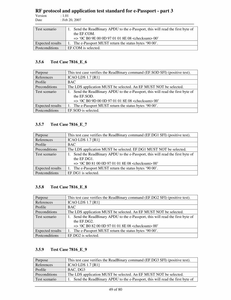
RF protocol and application test standard for e-Passport - part 3 Version : 1.01
Date : Feb 20, 2007
49 of 80
Test scenario 1. Send the ReadBinary APDU to the e-Passport, this will read the first byte of
the EF.COM.
=> ‘0C B0 9E 00 0D 97 01 01 8E 08 <checksum> 00’
Expected results 1. The e-Passport MUST return the status bytes ‘90 00’.
Postconditions EF.COM is selected.
3.5.6 Test Case 7816_E_6
Purpose This test case verifies the ReadBinary command (EF.SOD SFI) (positive test).
References ICAO LDS 1.7 [R1]
Profile BAC
Preconditions The LDS application MUST be selected. An EF MUST NOT be selected.
Test scenario 1. Send the ReadBinary APDU to the e-Passport, this will read the first byte of
the EF.SOD.
=> ‘0C B0 9D 00 0D 97 01 01 8E 08 <checksum> 00’
Expected results 1. The e-Passport MUST return the status bytes ‘90 00’.
Postconditions EF.SOD is selected.
3.5.7 Test Case 7816_E_7
Purpose This test case verifies the ReadBinary command (EF.DG1 SFI) (positive test).
References ICAO LDS 1.7 [R1]
Profile BAC
Preconditions The LDS application MUST be selected. EF.DG1 MUST NOT be selected.
Test scenario 1. Send the ReadBinary APDU to the e-Passport, this will read the first byte of
the EF.DG1.
=> ‘0C B0 81 00 0D 97 01 01 8E 08 <checksum> 00’
Expected results 1. The e-Passport MUST return the status bytes ‘90 00’.
Postconditions EF.DG1 is selected.
3.5.8 Test Case 7816_E_8
Purpose This test case verifies the ReadBinary command (EF.DG2 SFI) (positive test).
References ICAO LDS 1.7 [R1]
Profile BAC
Preconditions The LDS application MUST be selected. An EF MUST NOT be selected.
Test scenario 1. Send the ReadBinary APDU to the e-Passport, this will read the first byte of
the EF.DG2.
=> ‘0C B0 82 00 0D 97 01 01 8E 08 <checksum> 00’
Expected results 1. The e-Passport MUST return the status bytes ‘90 00’.
Postconditions EF.DG2 is selected.
3.5.9 Test Case 7816_E_9
Purpose This test case verifies the ReadBinary command (EF.DG3 SFI) (positive test).
References ICAO LDS 1.7 [R1]
Profile BAC, DG3
Preconditions The LDS application MUST be selected. An EF MUST NOT be selected.
Test scenario 1. Send the ReadBinary APDU to the e-Passport, this will read the first byte of
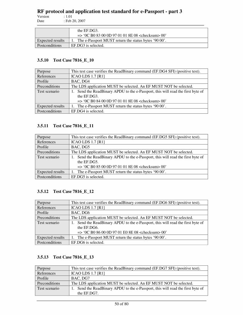
RF protocol and application test standard for e-Passport - part 3 Version : 1.01
Date : Feb 20, 2007
50 of 80
the EF.DG3.
=> ‘0C B0 83 00 0D 97 01 01 8E 08 <checksum> 00’
Expected results 1. The e-Passport MUST return the status bytes ‘90 00’.
Postconditions EF.DG3 is selected.
3.5.10 Test Case 7816_E_10
Purpose This test case verifies the ReadBinary command (EF.DG4 SFI) (positive test).
References ICAO LDS 1.7 [R1]
Profile BAC, DG4
Preconditions The LDS application MUST be selected. An EF MUST NOT be selected.
Test scenario 1. Send the ReadBinary APDU to the e-Passport, this will read the first byte of
the EF.DG3.
=> ‘0C B0 84 00 0D 97 01 01 8E 08 <checksum> 00’
Expected results 1. The e-Passport MUST return the status bytes ‘90 00’.
Postconditions EF.DG4 is selected.
3.5.11 Test Case 7816_E_11
Purpose This test case verifies the ReadBinary command (EF.DG5 SFI) (positive test).
References ICAO LDS 1.7 [R1]
Profile BAC, DG5
Preconditions The LDS application MUST be selected. An EF MUST NOT be selected.
Test scenario 1. Send the ReadBinary APDU to the e-Passport, this will read the first byte of
the EF.DG5.
=> ‘0C B0 85 00 0D 97 01 01 8E 08 <checksum> 00’
Expected results 1. The e-Passport MUST return the status bytes ‘90 00’.
Postconditions EF.DG5 is selected.
3.5.12 Test Case 7816_E_12
Purpose This test case verifies the ReadBinary command (EF.DG6 SFI) (positive test).
References ICAO LDS 1.7 [R1]
Profile BAC, DG6
Preconditions The LDS application MUST be selected. An EF MUST NOT be selected.
Test scenario 1. Send the ReadBinary APDU to the e-Passport, this will read the first byte of
the EF.DG6.
=> ‘0C B0 86 00 0D 97 01 E0 8E 08 <checksum> 00’
Expected results 1. The e-Passport MUST return the status bytes ‘90 00’.
Postconditions EF.DG6 is selected.
3.5.13 Test Case 7816_E_13
Purpose This test case verifies the ReadBinary command (EF.DG7 SFI) (positive test).
References ICAO LDS 1.7 [R1]
Profile BAC, DG7
Preconditions The LDS application MUST be selected. An EF MUST NOT be selected.
Test scenario 1. Send the ReadBinary APDU to the e-Passport, this will read the first byte of
the EF.DG7.
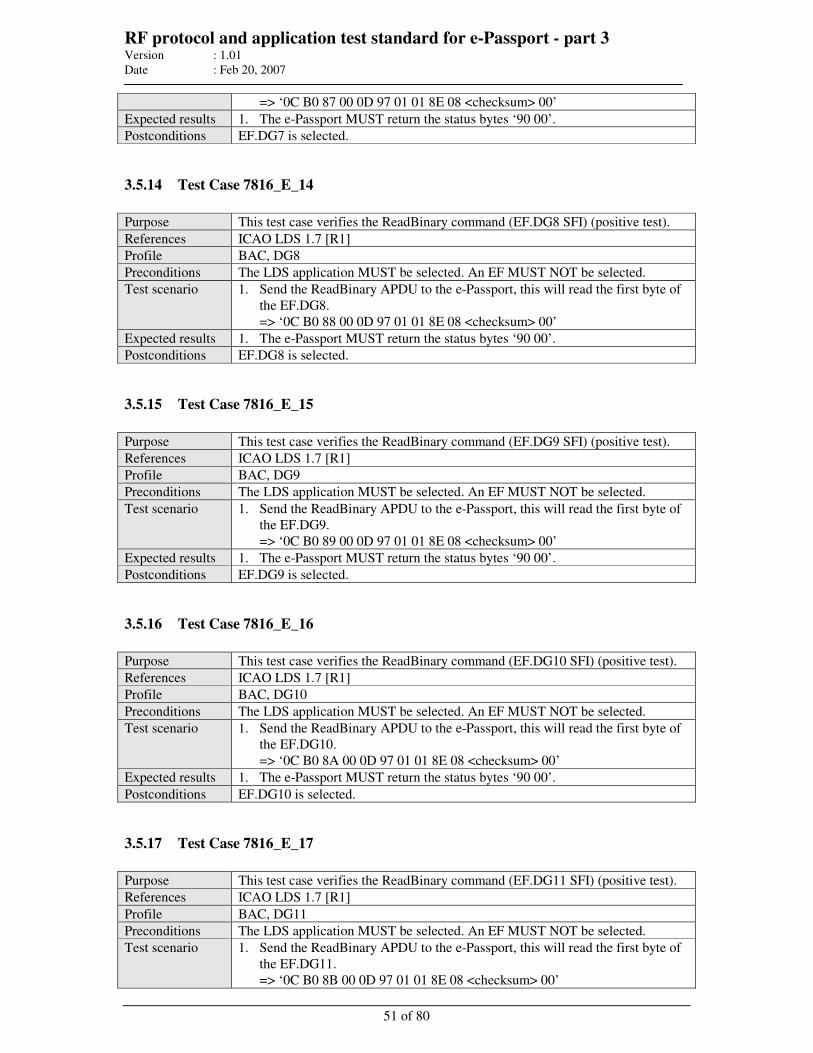
RF protocol and application test standard for e-Passport - part 3 Version : 1.01
Date : Feb 20, 2007
51 of 80
=> ‘0C B0 87 00 0D 97 01 01 8E 08 <checksum> 00’
Expected results 1. The e-Passport MUST return the status bytes ‘90 00’.
Postconditions EF.DG7 is selected.
3.5.14 Test Case 7816_E_14
Purpose This test case verifies the ReadBinary command (EF.DG8 SFI) (positive test).
References ICAO LDS 1.7 [R1]
Profile BAC, DG8
Preconditions The LDS application MUST be selected. An EF MUST NOT be selected.
Test scenario 1. Send the ReadBinary APDU to the e-Passport, this will read the first byte of
the EF.DG8.
=> ‘0C B0 88 00 0D 97 01 01 8E 08 <checksum> 00’
Expected results 1. The e-Passport MUST return the status bytes ‘90 00’.
Postconditions EF.DG8 is selected.
3.5.15 Test Case 7816_E_15
Purpose This test case verifies the ReadBinary command (EF.DG9 SFI) (positive test).
References ICAO LDS 1.7 [R1]
Profile BAC, DG9
Preconditions The LDS application MUST be selected. An EF MUST NOT be selected.
Test scenario 1. Send the ReadBinary APDU to the e-Passport, this will read the first byte of
the EF.DG9.
=> ‘0C B0 89 00 0D 97 01 01 8E 08 <checksum> 00’
Expected results 1. The e-Passport MUST return the status bytes ‘90 00’.
Postconditions EF.DG9 is selected.
3.5.16 Test Case 7816_E_16
Purpose This test case verifies the ReadBinary command (EF.DG10 SFI) (positive test).
References ICAO LDS 1.7 [R1]
Profile BAC, DG10
Preconditions The LDS application MUST be selected. An EF MUST NOT be selected.
Test scenario 1. Send the ReadBinary APDU to the e-Passport, this will read the first byte of
the EF.DG10.
=> ‘0C B0 8A 00 0D 97 01 01 8E 08 <checksum> 00’
Expected results 1. The e-Passport MUST return the status bytes ‘90 00’.
Postconditions EF.DG10 is selected.
3.5.17 Test Case 7816_E_17
Purpose This test case verifies the ReadBinary command (EF.DG11 SFI) (positive test).
References ICAO LDS 1.7 [R1]
Profile BAC, DG11
Preconditions The LDS application MUST be selected. An EF MUST NOT be selected.
Test scenario 1. Send the ReadBinary APDU to the e-Passport, this will read the first byte of
the EF.DG11.
=> ‘0C B0 8B 00 0D 97 01 01 8E 08 <checksum> 00’
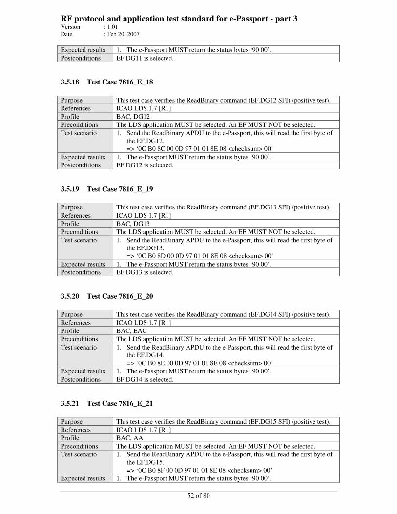
RF protocol and application test standard for e-Passport - part 3 Version : 1.01
Date : Feb 20, 2007
52 of 80
Expected results 1. The e-Passport MUST return the status bytes ‘90 00’.
Postconditions EF.DG11 is selected.
3.5.18 Test Case 7816_E_18
Purpose This test case verifies the ReadBinary command (EF.DG12 SFI) (positive test).
References ICAO LDS 1.7 [R1]
Profile BAC, DG12
Preconditions The LDS application MUST be selected. An EF MUST NOT be selected.
Test scenario 1. Send the ReadBinary APDU to the e-Passport, this will read the first byte of
the EF.DG12.
=> ‘0C B0 8C 00 0D 97 01 01 8E 08 <checksum> 00’
Expected results 1. The e-Passport MUST return the status bytes ‘90 00’.
Postconditions EF.DG12 is selected.
3.5.19 Test Case 7816_E_19
Purpose This test case verifies the ReadBinary command (EF.DG13 SFI) (positive test).
References ICAO LDS 1.7 [R1]
Profile BAC, DG13
Preconditions The LDS application MUST be selected. An EF MUST NOT be selected.
Test scenario 1. Send the ReadBinary APDU to the e-Passport, this will read the first byte of
the EF.DG13.
=> ‘0C B0 8D 00 0D 97 01 01 8E 08 <checksum> 00’
Expected results 1. The e-Passport MUST return the status bytes ‘90 00’.
Postconditions EF.DG13 is selected.
3.5.20 Test Case 7816_E_20
Purpose This test case verifies the ReadBinary command (EF.DG14 SFI) (positive test).
References ICAO LDS 1.7 [R1]
Profile BAC, EAC
Preconditions The LDS application MUST be selected. An EF MUST NOT be selected.
Test scenario 1. Send the ReadBinary APDU to the e-Passport, this will read the first byte of
the EF.DG14.
=> ‘0C B0 8E 00 0D 97 01 01 8E 08 <checksum> 00’
Expected results 1. The e-Passport MUST return the status bytes ‘90 00’.
Postconditions EF.DG14 is selected.
3.5.21 Test Case 7816_E_21
Purpose This test case verifies the ReadBinary command (EF.DG15 SFI) (positive test).
References ICAO LDS 1.7 [R1]
Profile BAC, AA
Preconditions The LDS application MUST be selected. An EF MUST NOT be selected.
Test scenario 1. Send the ReadBinary APDU to the e-Passport, this will read the first byte of
the EF.DG15.
=> ‘0C B0 8F 00 0D 97 01 01 8E 08 <checksum> 00’
Expected results 1. The e-Passport MUST return the status bytes ‘90 00’.
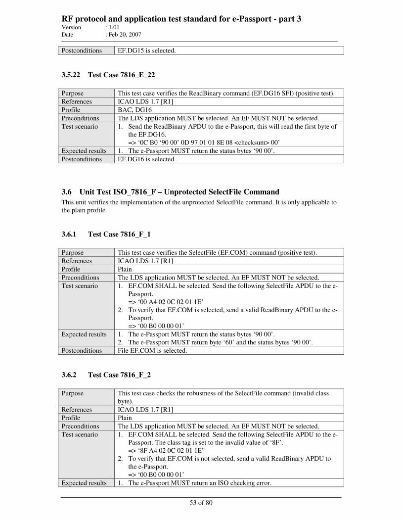
RF protocol and application test standard for e-Passport - part 3 Version : 1.01
Date : Feb 20, 2007
53 of 80
Postconditions EF.DG15 is selected.
3.5.22 Test Case 7816_E_22
Purpose This test case verifies the ReadBinary command (EF.DG16 SFI) (positive test).
References ICAO LDS 1.7 [R1]
Profile BAC, DG16
Preconditions The LDS application MUST be selected. An EF MUST NOT be selected.
Test scenario 1. Send the ReadBinary APDU to the e-Passport, this will read the first byte of
the EF.DG16.
=> ‘0C B0 ‘90 00’ 0D 97 01 01 8E 08 <checksum> 00’
Expected results 1. The e-Passport MUST return the status bytes ‘90 00’.
Postconditions EF.DG16 is selected.
3.6 Unit Test ISO_7816_F – Unprotected SelectFile Command
This unit verifies the implementation of the unprotected SelectFile command. It is only applicable to
the plain profile.
3.6.1 Test Case 7816_F_1
Purpose This test case verifies the SelectFile (EF.COM) command (positive test).
References ICAO LDS 1.7 [R1]
Profile Plain
Preconditions The LDS application MUST be selected. An EF MUST NOT be selected.
Test scenario 1. EF.COM SHALL be selected. Send the following SelectFile APDU to the e-
Passport.
=> ‘00 A4 02 0C 02 01 1E’
2. To verify that EF.COM is selected, send a valid ReadBinary APDU to the e-
Passport.
=> ‘00 B0 00 00 01’
Expected results 1. The e-Passport MUST return the status bytes ‘90 00’.
2. The e-Passport MUST return byte ‘60’ and the status bytes ‘90 00’.
Postconditions File EF.COM is selected.
3.6.2 Test Case 7816_F_2
Purpose This test case checks the robustness of the SelectFile command (invalid class
byte).
References ICAO LDS 1.7 [R1]
Profile Plain
Preconditions The LDS application MUST be selected. An EF MUST NOT be selected.
Test scenario 1. EF.COM SHALL be selected. Send the following SelectFile APDU to the e-
Passport. The class tag is set to the invalid value of ‘8F’.
=> ‘8F A4 02 0C 02 01 1E’
2. To verify that EF.COM is not selected, send a valid ReadBinary APDU to
the e-Passport.
=> ‘00 B0 00 00 01’
Expected results 1. The e-Passport MUST return an ISO checking error.
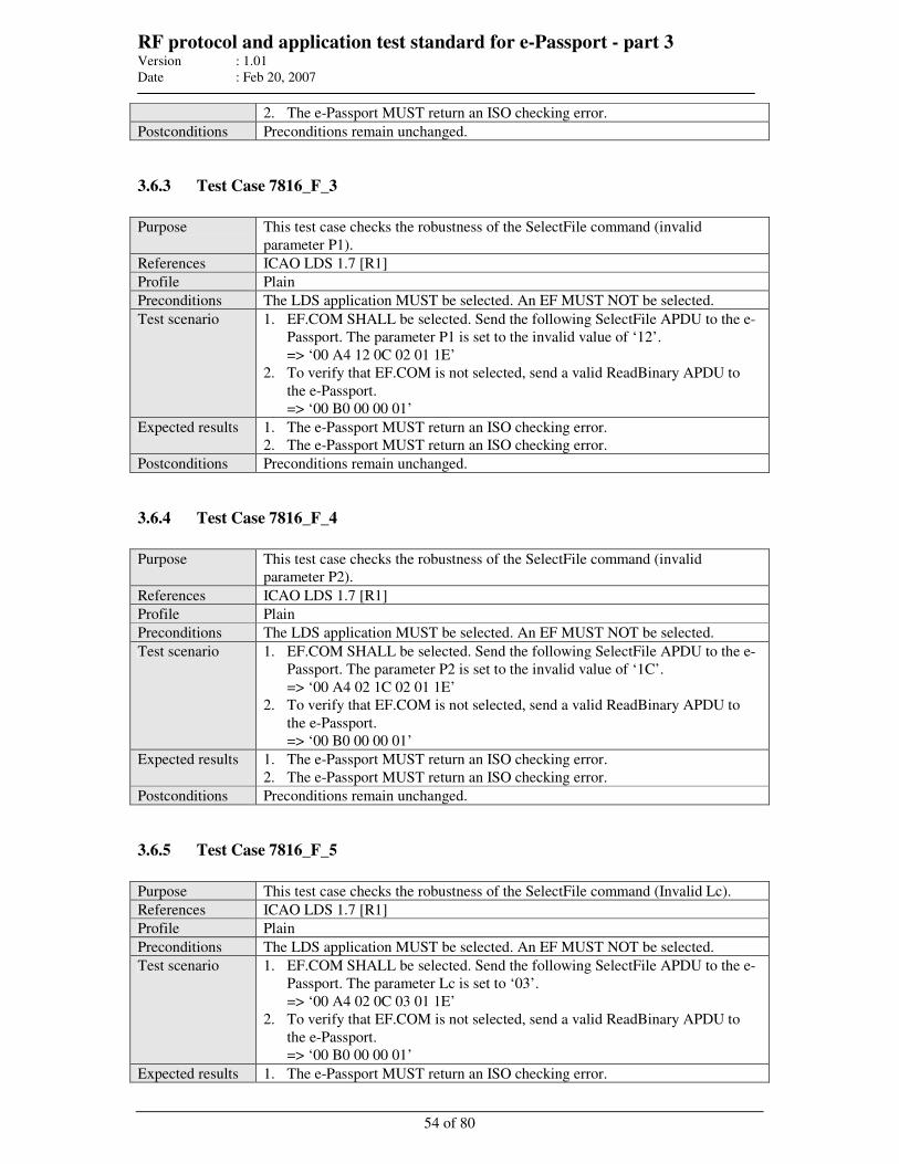
RF protocol and application test standard for e-Passport - part 3 Version : 1.01
Date : Feb 20, 2007
54 of 80
2. The e-Passport MUST return an ISO checking error.
Postconditions Preconditions remain unchanged.
3.6.3 Test Case 7816_F_3
Purpose This test case checks the robustness of the SelectFile command (invalid
parameter P1).
References ICAO LDS 1.7 [R1]
Profile Plain
Preconditions The LDS application MUST be selected. An EF MUST NOT be selected.
Test scenario 1. EF.COM SHALL be selected. Send the following SelectFile APDU to the e-
Passport. The parameter P1 is set to the invalid value of ‘12’.
=> ‘00 A4 12 0C 02 01 1E’
2. To verify that EF.COM is not selected, send a valid ReadBinary APDU to
the e-Passport.
=> ‘00 B0 00 00 01’
Expected results 1. The e-Passport MUST return an ISO checking error.
2. The e-Passport MUST return an ISO checking error.
Postconditions Preconditions remain unchanged.
3.6.4 Test Case 7816_F_4
Purpose This test case checks the robustness of the SelectFile command (invalid
parameter P2).
References ICAO LDS 1.7 [R1]
Profile Plain
Preconditions The LDS application MUST be selected. An EF MUST NOT be selected.
Test scenario 1. EF.COM SHALL be selected. Send the following SelectFile APDU to the e-
Passport. The parameter P2 is set to the invalid value of ‘1C’.
=> ‘00 A4 02 1C 02 01 1E’
2. To verify that EF.COM is not selected, send a valid ReadBinary APDU to
the e-Passport.
=> ‘00 B0 00 00 01’
Expected results 1. The e-Passport MUST return an ISO checking error.
2. The e-Passport MUST return an ISO checking error.
Postconditions Preconditions remain unchanged.
3.6.5 Test Case 7816_F_5
Purpose This test case checks the robustness of the SelectFile command (Invalid Lc).
References ICAO LDS 1.7 [R1]
Profile Plain
Preconditions The LDS application MUST be selected. An EF MUST NOT be selected.
Test scenario 1. EF.COM SHALL be selected. Send the following SelectFile APDU to the e-
Passport. The parameter Lc is set to ‘03’.
=> ‘00 A4 02 0C 03 01 1E’
2. To verify that EF.COM is not selected, send a valid ReadBinary APDU to
the e-Passport.
=> ‘00 B0 00 00 01’
Expected results 1. The e-Passport MUST return an ISO checking error.
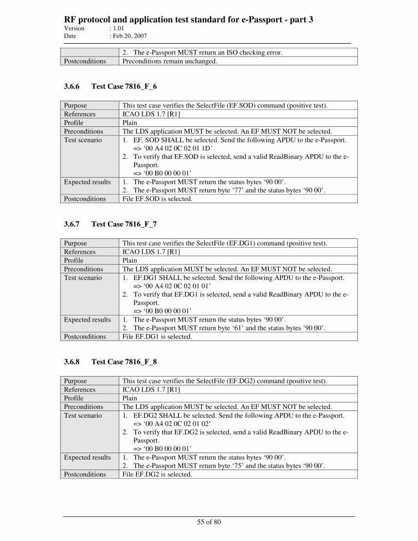
RF protocol and application test standard for e-Passport - part 3 Version : 1.01
Date : Feb 20, 2007
55 of 80
2. The e-Passport MUST return an ISO checking error.
Postconditions Preconditions remain unchanged.
3.6.6 Test Case 7816_F_6
Purpose This test case verifies the SelectFile (EF.SOD) command (positive test).
References ICAO LDS 1.7 [R1]
Profile Plain
Preconditions The LDS application MUST be selected. An EF MUST NOT be selected.
Test scenario 1. EF. SOD SHALL be selected. Send the following APDU to the e-Passport.
=> ‘00 A4 02 0C 02 01 1D’
2. To verify that EF.SOD is selected, send a valid ReadBinary APDU to the e-
Passport.
=> ‘00 B0 00 00 01’
Expected results 1. The e-Passport MUST return the status bytes ‘90 00’.
2. The e-Passport MUST return byte ‘77’ and the status bytes ‘90 00’.
Postconditions File EF.SOD is selected.
3.6.7 Test Case 7816_F_7
Purpose This test case verifies the SelectFile (EF.DG1) command (positive test).
References ICAO LDS 1.7 [R1]
Profile Plain
Preconditions The LDS application MUST be selected. An EF MUST NOT be selected.
Test scenario 1. EF.DG1 SHALL be selected. Send the following APDU to the e-Passport.
=> ‘00 A4 02 0C 02 01 01’
2. To verify that EF.DG1 is selected, send a valid ReadBinary APDU to the e-
Passport.
=> ‘00 B0 00 00 01’
Expected results 1. The e-Passport MUST return the status bytes ‘90 00’.
2. The e-Passport MUST return byte ‘61’ and the status bytes ‘90 00’.
Postconditions File EF.DG1 is selected.
3.6.8 Test Case 7816_F_8
Purpose This test case verifies the SelectFile (EF.DG2) command (positive test).
References ICAO LDS 1.7 [R1]
Profile Plain
Preconditions The LDS application MUST be selected. An EF MUST NOT be selected.
Test scenario 1. EF.DG2 SHALL be selected. Send the following APDU to the e-Passport.
=> ‘00 A4 02 0C 02 01 02’
2. To verify that EF.DG2 is selected, send a valid ReadBinary APDU to the e-
Passport.
=> ‘00 B0 00 00 01’
Expected results 1. The e-Passport MUST return the status bytes ‘90 00’.
2. The e-Passport MUST return byte ‘75’ and the status bytes ‘90 00’.
Postconditions File EF.DG2 is selected.
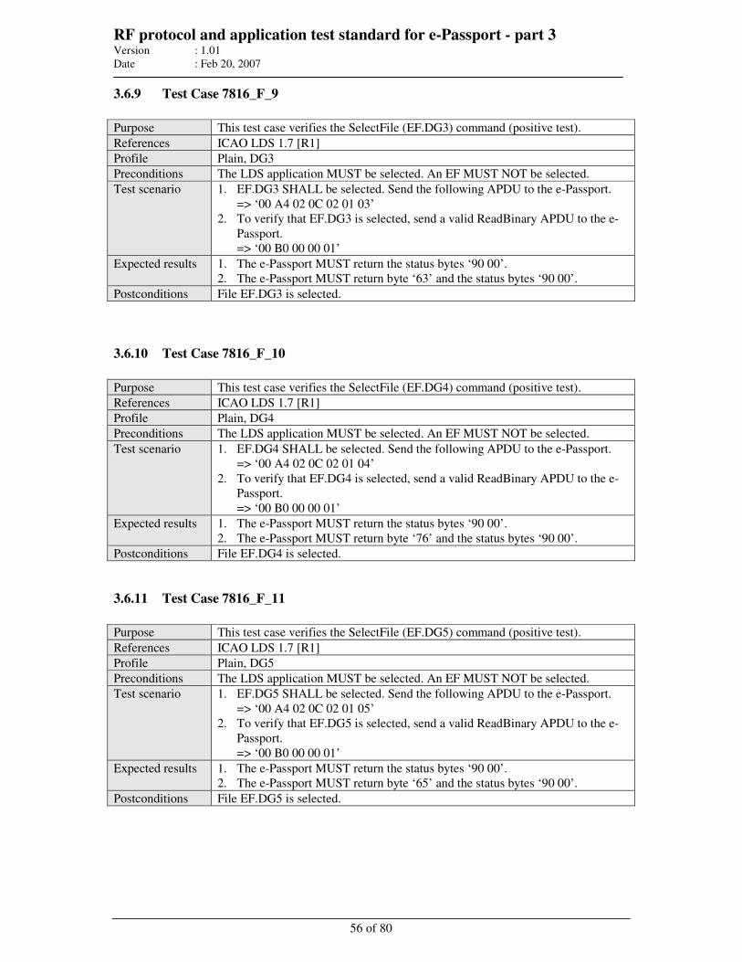
RF protocol and application test standard for e-Passport - part 3 Version : 1.01
Date : Feb 20, 2007
56 of 80
3.6.9 Test Case 7816_F_9
Purpose This test case verifies the SelectFile (EF.DG3) command (positive test).
References ICAO LDS 1.7 [R1]
Profile Plain, DG3
Preconditions The LDS application MUST be selected. An EF MUST NOT be selected.
Test scenario 1. EF.DG3 SHALL be selected. Send the following APDU to the e-Passport.
=> ‘00 A4 02 0C 02 01 03’
2. To verify that EF.DG3 is selected, send a valid ReadBinary APDU to the e-
Passport.
=> ‘00 B0 00 00 01’
Expected results 1. The e-Passport MUST return the status bytes ‘90 00’.
2. The e-Passport MUST return byte ‘63’ and the status bytes ‘90 00’.
Postconditions File EF.DG3 is selected.
3.6.10 Test Case 7816_F_10
Purpose This test case verifies the SelectFile (EF.DG4) command (positive test).
References ICAO LDS 1.7 [R1]
Profile Plain, DG4
Preconditions The LDS application MUST be selected. An EF MUST NOT be selected.
Test scenario 1. EF.DG4 SHALL be selected. Send the following APDU to the e-Passport.
=> ‘00 A4 02 0C 02 01 04’
2. To verify that EF.DG4 is selected, send a valid ReadBinary APDU to the e-
Passport.
=> ‘00 B0 00 00 01’
Expected results 1. The e-Passport MUST return the status bytes ‘90 00’.
2. The e-Passport MUST return byte ‘76’ and the status bytes ‘90 00’.
Postconditions File EF.DG4 is selected.
3.6.11 Test Case 7816_F_11
Purpose This test case verifies the SelectFile (EF.DG5) command (positive test).
References ICAO LDS 1.7 [R1]
Profile Plain, DG5
Preconditions The LDS application MUST be selected. An EF MUST NOT be selected.
Test scenario 1. EF.DG5 SHALL be selected. Send the following APDU to the e-Passport.
=> ‘00 A4 02 0C 02 01 05’
2. To verify that EF.DG5 is selected, send a valid ReadBinary APDU to the e-
Passport.
=> ‘00 B0 00 00 01’
Expected results 1. The e-Passport MUST return the status bytes ‘90 00’.
2. The e-Passport MUST return byte ‘65’ and the status bytes ‘90 00’.
Postconditions File EF.DG5 is selected.

RF protocol and application test standard for e-Passport - part 3 Version : 1.01
Date : Feb 20, 2007
57 of 80
3.6.12 Test Case 7816_F_12
Purpose This test case verifies the SelectFile (EF.DG6) command (positive test).
References ICAO LDS 1.7 [R1]
Profile Plain, DG6
Preconditions The LDS application MUST be selected. An EF MUST NOT be selected.
Test scenario 1. EF.DG6 SHALL be selected. Send the following APDU to the e-Passport.
=> ‘00 A4 02 0C 02 01 06’
2. To verify that EF.DG6 is selected, send a valid ReadBinary APDU to the e-
Passport.
=> ‘00 B0 00 00 01’
Expected results 1. The e-Passport MUST return the status bytes ‘90 00’.
2. The e-Passport MUST return byte ‘66’ and the status bytes ‘90 00’.
Postconditions File EF.DG6 is selected.
3.6.13 Test Case 7816_F_13
Purpose This test case verifies the SelectFile (EF.DG7) command (positive test).
References ICAO LDS 1.7 [R1]
Profile Plain, DG7
Preconditions The LDS application MUST be selected. An EF MUST NOT be selected.
Test scenario 1. EF.DG7 SHALL be selected. Send the following APDU to the e-Passport.
=> ‘00 A4 02 0C 02 01 07’
2. To verify that EF.DG7 is selected, send a valid ReadBinary APDU to the e-
Passport.
=> ‘00 B0 00 00 01’
Expected results 1. The e-Passport MUST return the status bytes ‘90 00’.
2. The e-Passport MUST return byte ‘67’ and the status bytes ‘90 00’.
Postconditions File EF.DG7 is selected.
3.6.14 Test Case 7816_F_14
Purpose This test case verifies the SelectFile (EF.DG8) command (positive test).
References ICAO LDS 1.7 [R1]
Profile Plain, DG8
Preconditions The LDS application MUST be selected. An EF MUST NOT be selected.
Test scenario 1. EF.DG8 SHALL be selected. Send the following APDU to the e-Passport.
=> ‘00 A4 02 0C 02 01 08’
2. To verify that EF.DG8 is selected, send a valid ReadBinary APDU to the e-
Passport.
=> ‘00 B0 00 00 01’
Expected results 1. The e-Passport MUST return the status bytes ‘90 00’.
2. The e-Passport MUST return byte ‘68’ and the status bytes ‘90 00’.
Postconditions File EF.DG8 is selected.

RF protocol and application test standard for e-Passport - part 3 Version : 1.01
Date : Feb 20, 2007
58 of 80
3.6.15 Test Case 7816_F_15
Purpose This test case verifies the SelectFile (EF.DG9) command (positive test).
References ICAO LDS 1.7 [R1]
Profile Plain, DG9
Preconditions The LDS application MUST be selected. An EF MUST NOT be selected.
Test scenario 1. EF.DG9 SHALL be selected. Send the following APDU to the e-Passport.
=> ‘00 A4 02 0C 02 01 09’
2. To verify that EF.DG9 is selected, send a valid ReadBinary APDU to the e-
Passport.
=> ‘00 B0 00 00 01’
Expected results 1. The e-Passport MUST return the status bytes ‘90 00’.
2. The e-Passport MUST return byte ‘69’ and the status bytes ‘90 00’.
Postconditions File EF.DG9 is selected.
3.6.16 Test Case 7816_F_16
Purpose This test case verifies the SelectFile (EF.DG10) command (positive test).
References ICAO LDS 1.7 [R1]
Profile Plain, DG10
Preconditions The LDS application MUST be selected. An EF MUST NOT be selected.
Test scenario 1. EF.DG10 SHALL be selected. Send the following APDU to the e-Passport.
=> ‘00 A4 02 0C 02 01 0A’
2. To verify that EF.DG10 is selected, send a valid ReadBinary APDU to the e-
Passport.
=> ‘00 B0 00 00 01’
Expected results 1. The e-Passport MUST return the status bytes ‘90 00’.
2. The e-Passport MUST return byte ‘6A’ and the status bytes ‘90 00’.
Postconditions File EF.DG10 is selected.
3.6.17 Test Case 7816_F_17
Purpose This test case verifies the SelectFile (EF.DG11) command (positive test).
References ICAO LDS 1.7 [R1]
Profile Plain, DG11
Preconditions The LDS application MUST be selected. An EF MUST NOT be selected.
Test scenario 1. EF.DG11 SHALL be selected. Send the following APDU to the e-Passport.
=> ‘00 A4 02 0C 02 01 0B’
2. To verify that EF.DG11 is selected, send a valid ReadBinary APDU to the e-
Passport.
=> ‘00 B0 00 00 01’
Expected results 1. The e-Passport MUST return the status bytes ‘90 00’.
2. The e-Passport MUST return byte ‘6B’ and the status bytes ‘90 00’.
Postconditions File EF.DG11 is selected.

RF protocol and application test standard for e-Passport - part 3 Version : 1.01
Date : Feb 20, 2007
59 of 80
3.6.18 Test Case 7816_F_18
Purpose This test case verifies the SelectFile (EF.DG12) command (positive test).
References ICAO LDS 1.7 [R1]
Profile Plain, DG12
Preconditions The LDS application MUST be selected. An EF MUST NOT be selected.
Test scenario 1. EF.DG12 SHALL be selected. Send the following APDU to the e-Passport.
=> ‘00 A4 02 0C 02 01 0C’
2. To verify that EF.DG12 is selected, send a valid ReadBinary APDU to the e-
Passport.
=> ‘00 B0 00 00 01’
Expected results 1. The e-Passport MUST return the status bytes ‘90 00’.
2. The e-Passport MUST return byte ‘6C’ and the status bytes ‘90 00’.
Postconditions File EF.DG12 is selected.
3.6.19 Test Case 7816_F_19
Purpose This test case verifies the SelectFile (EF.DG13) command (positive test).
References ICAO LDS 1.7 [R1]
Profile Plain, DG13
Preconditions The LDS application MUST be selected. An EF MUST NOT be selected.
Test scenario 1. EF.DG13 SHALL be selected. Send the following APDU to the e-Passport.
=> ‘00 A4 02 0C 02 01 0D’
2. To verify that EF.DG13 is selected, send a valid ReadBinary APDU to the e-
Passport.
=> ‘00 B0 00 00 01’
Expected results 1. The e-Passport MUST return the status bytes ‘90 00’.
2. The e-Passport MUST return byte ‘6D’ and the status bytes ‘90 00’.
Postconditions File EF.DG13 is selected.
3.6.20 Test Case 7816_F_20
Purpose This test case verifies the SelectFile (EF.DG14) command (positive test).
References ICAO LDS 1.7 [R1]
Profile Plain, EAC
Preconditions The LDS application MUST be selected. An EF MUST NOT be selected.
Test scenario 1. EF.DG14 SHALL be selected. Send the following APDU to the e-Passport.
=> ‘00 A4 02 0C 02 01 0E’
2. To verify that EF.DG14 is selected, send a valid ReadBinary APDU to the e-
Passport.
=> ‘00 B0 00 00 01’
Expected results 1. The e-Passport MUST return the status bytes ‘90 00’.
2. The e-Passport MUST return byte ‘6E’ and the status bytes ‘90 00’.
Postconditions File EF.DG14 is selected.
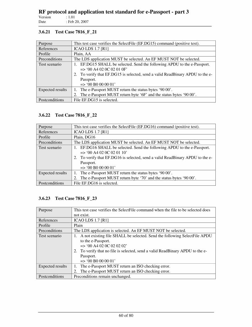
RF protocol and application test standard for e-Passport - part 3 Version : 1.01
Date : Feb 20, 2007
60 of 80
3.6.21 Test Case 7816_F_21
Purpose This test case verifies the SelectFile (EF.DG15) command (positive test).
References ICAO LDS 1.7 [R1]
Profile Plain, AA
Preconditions The LDS application MUST be selected. An EF MUST NOT be selected.
Test scenario 1. EF.DG15 SHALL be selected. Send the following APDU to the e-Passport.
=> ‘00 A4 02 0C 02 01 0F’
2. To verify that EF.DG15 is selected, send a valid ReadBinary APDU to the e-
Passport.
=> ‘00 B0 00 00 01’
Expected results 1. The e-Passport MUST return the status bytes ‘90 00’.
2. The e-Passport MUST return byte ‘6F’ and the status bytes ‘90 00’.
Postconditions File EF.DG15 is selected.
3.6.22 Test Case 7816_F_22
Purpose This test case verifies the SelectFile (EF.DG16) command (positive test).
References ICAO LDS 1.7 [R1]
Profile Plain, DG16
Preconditions The LDS application MUST be selected. An EF MUST NOT be selected.
Test scenario 1. EF.DG16 SHALL be selected. Send the following APDU to the e-Passport.
=> ‘00 A4 02 0C 02 01 10’
2. To verify that EF.DG16 is selected, send a valid ReadBinary APDU to the e-
Passport.
=> ‘00 B0 00 00 01’
Expected results 1. The e-Passport MUST return the status bytes ‘90 00’.
2. The e-Passport MUST return byte ‘70’ and the status bytes ‘90 00’.
Postconditions File EF.DG16 is selected.
3.6.23 Test Case 7816_F_23
Purpose This test case verifies the SelectFile command when the file to be selected does
not exist.
References ICAO LDS 1.7 [R1]
Profile Plain
Preconditions The LDS application is selected. An EF MUST NOT be selected.
Test scenario 1. A not existing file SHALL be selected. Send the following SelectFile APDU
to the e-Passport.
=> ‘00 A4 02 0C 02 02 02’
2. To verify that no file is selected, send a valid ReadBinary APDU to the e-
Passport.
=> ‘00 B0 00 00 01’
Expected results 1. The e-Passport MUST return an ISO checking error.
2. The e-Passport MUST return an ISO checking error.
Postconditions Preconditions remain unchanged.
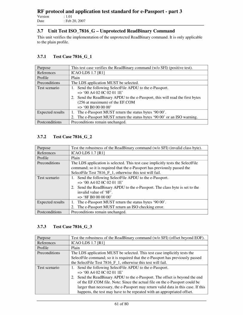
RF protocol and application test standard for e-Passport - part 3 Version : 1.01
Date : Feb 20, 2007
61 of 80
3.7 Unit Test ISO_7816_G – Unprotected ReadBinary Command
This unit verifies the implementation of the unprotected ReadBinary command. It is only applicable
to the plain profile.
3.7.1 Test Case 7816_G_1
Purpose This test case verifies the ReadBinary command (w/o SFI) (positive test).
References ICAO LDS 1.7 [R1]
Profile Plain
Preconditions The LDS application MUST be selected.
Test scenario 1. Send the following SelectFile APDU to the e-Passport.
=> ‘00 A4 02 0C 02 01 1E’
2. Send the ReadBinary APDU to the e-Passport, this will read the first bytes
(256 at maximum) of the EF.COM
=> ‘00 B0 00 00 00’
Expected results 1. The e-Passport MUST return the status bytes ‘90 00’.
2. The e-Passport MUST return the status bytes ‘90 00’ or an ISO warning.
Postconditions Preconditions remain unchanged.
3.7.2 Test Case 7816_G_2
Purpose Test the robustness of the ReadBinary command (w/o SFI) (invalid class byte).
References ICAO LDS 1.7 [R1]
Profile Plain
Preconditions The LDS application is selected. This test case implicitly tests the SelectFile
command; so it is required that the e-Passport has previously passed the
SelectFile Test 7816_F_1, otherwise this test will fail.
Test scenario 1. Send the following SelectFile APDU to the e-Passport.
=> ‘00 A4 02 0C 02 01 1E’
2. Send the ReadBinary APDU to the e-Passport. The class byte is set to the
invalid value of ‘8F’.
=> ‘8F B0 00 00 00’
Expected results 1. The e-Passport MUST return the status bytes ‘90 00’.
2. The e-Passport MUST return an ISO checking error.
Postconditions Preconditions remain unchanged.
3.7.3 Test Case 7816_G_3
Purpose Test the robustness of the ReadBinary command (w/o SFI) (offset beyond EOF).
References ICAO LDS 1.7 [R1]
Profile Plain
Preconditions The LDS application MUST be selected. This test case implicitly tests the
SelectFile command; so it is required that the e-Passport has previously passed
the SelectFile Test 7816_F_1, otherwise this test will fail.
Test scenario 1. Send the following SelectFile APDU to the e-Passport.
=> ‘00 A4 02 0C 02 01 1E’
2. Send the ReadBinary APDU to the e-Passport. The offset is beyond the end
of the EF.COM file. Note: Since the actual file on the e-Passport could be
larger than necessary, the e-Passport may return valid data in this case. If this
happens, the test may have to be repeated with an appropriated offset.
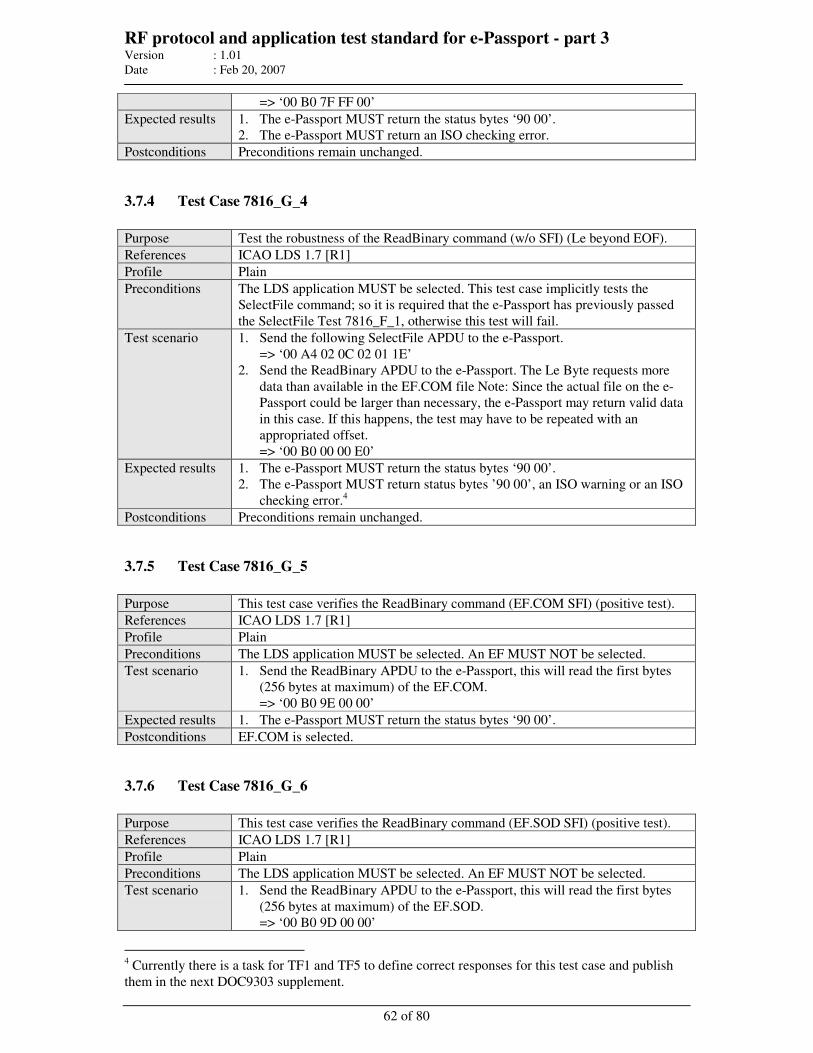
RF protocol and application test standard for e-Passport - part 3 Version : 1.01
Date : Feb 20, 2007
62 of 80
=> ‘00 B0 7F FF 00’
Expected results 1. The e-Passport MUST return the status bytes ‘90 00’.
2. The e-Passport MUST return an ISO checking error.
Postconditions Preconditions remain unchanged.
3.7.4 Test Case 7816_G_4
Purpose Test the robustness of the ReadBinary command (w/o SFI) (Le beyond EOF).
References ICAO LDS 1.7 [R1]
Profile Plain
Preconditions The LDS application MUST be selected. This test case implicitly tests the
SelectFile command; so it is required that the e-Passport has previously passed
the SelectFile Test 7816_F_1, otherwise this test will fail.
Test scenario 1. Send the following SelectFile APDU to the e-Passport.
=> ‘00 A4 02 0C 02 01 1E’
2. Send the ReadBinary APDU to the e-Passport. The Le Byte requests more
data than available in the EF.COM file Note: Since the actual file on the e-
Passport could be larger than necessary, the e-Passport may return valid data
in this case. If this happens, the test may have to be repeated with an
appropriated offset.
=> ‘00 B0 00 00 E0’
Expected results 1. The e-Passport MUST return the status bytes ‘90 00’.
2. The e-Passport MUST return status bytes ’90 00’, an ISO warning or an ISO
checking error.4
Postconditions Preconditions remain unchanged.
3.7.5 Test Case 7816_G_5
Purpose This test case verifies the ReadBinary command (EF.COM SFI) (positive test).
References ICAO LDS 1.7 [R1]
Profile Plain
Preconditions The LDS application MUST be selected. An EF MUST NOT be selected.
Test scenario 1. Send the ReadBinary APDU to the e-Passport, this will read the first bytes
(256 bytes at maximum) of the EF.COM.
=> ‘00 B0 9E 00 00’
Expected results 1. The e-Passport MUST return the status bytes ‘90 00’.
Postconditions EF.COM is selected.
3.7.6 Test Case 7816_G_6
Purpose This test case verifies the ReadBinary command (EF.SOD SFI) (positive test).
References ICAO LDS 1.7 [R1]
Profile Plain
Preconditions The LDS application MUST be selected. An EF MUST NOT be selected.
Test scenario 1. Send the ReadBinary APDU to the e-Passport, this will read the first bytes
(256 bytes at maximum) of the EF.SOD.
=> ‘00 B0 9D 00 00’
4 Currently there is a task for TF1 and TF5 to define correct responses for this test case and publish
them in the next DOC9303 supplement.
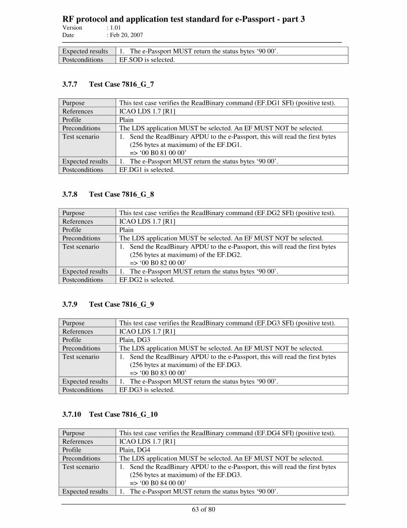
RF protocol and application test standard for e-Passport - part 3 Version : 1.01
Date : Feb 20, 2007
63 of 80
Expected results 1. The e-Passport MUST return the status bytes ‘90 00’.
Postconditions EF.SOD is selected.
3.7.7 Test Case 7816_G_7
Purpose This test case verifies the ReadBinary command (EF.DG1 SFI) (positive test).
References ICAO LDS 1.7 [R1]
Profile Plain
Preconditions The LDS application MUST be selected. An EF MUST NOT be selected.
Test scenario 1. Send the ReadBinary APDU to the e-Passport, this will read the first bytes
(256 bytes at maximum) of the EF.DG1.
=> ‘00 B0 81 00 00’
Expected results 1. The e-Passport MUST return the status bytes ‘90 00’.
Postconditions EF.DG1 is selected.
3.7.8 Test Case 7816_G_8
Purpose This test case verifies the ReadBinary command (EF.DG2 SFI) (positive test).
References ICAO LDS 1.7 [R1]
Profile Plain
Preconditions The LDS application MUST be selected. An EF MUST NOT be selected.
Test scenario 1. Send the ReadBinary APDU to the e-Passport, this will read the first bytes
(256 bytes at maximum) of the EF.DG2.
=> ‘00 B0 82 00 00’
Expected results 1. The e-Passport MUST return the status bytes ‘90 00’.
Postconditions EF.DG2 is selected.
3.7.9 Test Case 7816_G_9
Purpose This test case verifies the ReadBinary command (EF.DG3 SFI) (positive test).
References ICAO LDS 1.7 [R1]
Profile Plain, DG3
Preconditions The LDS application MUST be selected. An EF MUST NOT be selected.
Test scenario 1. Send the ReadBinary APDU to the e-Passport, this will read the first bytes
(256 bytes at maximum) of the EF.DG3.
=> ‘00 B0 83 00 00’
Expected results 1. The e-Passport MUST return the status bytes ‘90 00’.
Postconditions EF.DG3 is selected.
3.7.10 Test Case 7816_G_10
Purpose This test case verifies the ReadBinary command (EF.DG4 SFI) (positive test).
References ICAO LDS 1.7 [R1]
Profile Plain, DG4
Preconditions The LDS application MUST be selected. An EF MUST NOT be selected.
Test scenario 1. Send the ReadBinary APDU to the e-Passport, this will read the first bytes
(256 bytes at maximum) of the EF.DG3.
=> ‘00 B0 84 00 00’
Expected results 1. The e-Passport MUST return the status bytes ‘90 00’.
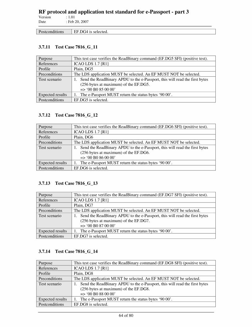
RF protocol and application test standard for e-Passport - part 3 Version : 1.01
Date : Feb 20, 2007
64 of 80
Postconditions EF.DG4 is selected.
3.7.11 Test Case 7816_G_11
Purpose This test case verifies the ReadBinary command (EF.DG5 SFI) (positive test).
References ICAO LDS 1.7 [R1]
Profile Plain, DG5
Preconditions The LDS application MUST be selected. An EF MUST NOT be selected.
Test scenario 1. Send the ReadBinary APDU to the e-Passport, this will read the first bytes
(256 bytes at maximum) of the EF.DG5.
=> ‘00 B0 85 00 00’
Expected results 1. The e-Passport MUST return the status bytes ‘90 00’.
Postconditions EF.DG5 is selected.
3.7.12 Test Case 7816_G_12
Purpose This test case verifies the ReadBinary command (EF.DG6 SFI) (positive test).
References ICAO LDS 1.7 [R1]
Profile Plain, DG6
Preconditions The LDS application MUST be selected. An EF MUST NOT be selected.
Test scenario 1. Send the ReadBinary APDU to the e-Passport, this will read the first bytes
(256 bytes at maximum) of the EF.DG6.
=> ‘00 B0 86 00 00’
Expected results 1. The e-Passport MUST return the status bytes ‘90 00’.
Postconditions EF.DG6 is selected.
3.7.13 Test Case 7816_G_13
Purpose This test case verifies the ReadBinary command (EF.DG7 SFI) (positive test).
References ICAO LDS 1.7 [R1]
Profile Plain, DG7
Preconditions The LDS application MUST be selected. An EF MUST NOT be selected.
Test scenario 1. Send the ReadBinary APDU to the e-Passport, this will read the first bytes
(256 bytes at maximum) of the EF.DG7.
=> ‘00 B0 87 00 00’
Expected results 1. The e-Passport MUST return the status bytes ‘90 00’.
Postconditions EF.DG7 is selected.
3.7.14 Test Case 7816_G_14
Purpose This test case verifies the ReadBinary command (EF.DG8 SFI) (positive test).
References ICAO LDS 1.7 [R1]
Profile Plain, DG8
Preconditions The LDS application MUST be selected. An EF MUST NOT be selected.
Test scenario 1. Send the ReadBinary APDU to the e-Passport, this will read the first bytes
(256 bytes at maximum) of the EF.DG8.
=> ‘00 B0 88 00 00’
Expected results 1. The e-Passport MUST return the status bytes ‘90 00’.
Postconditions EF.DG8 is selected.
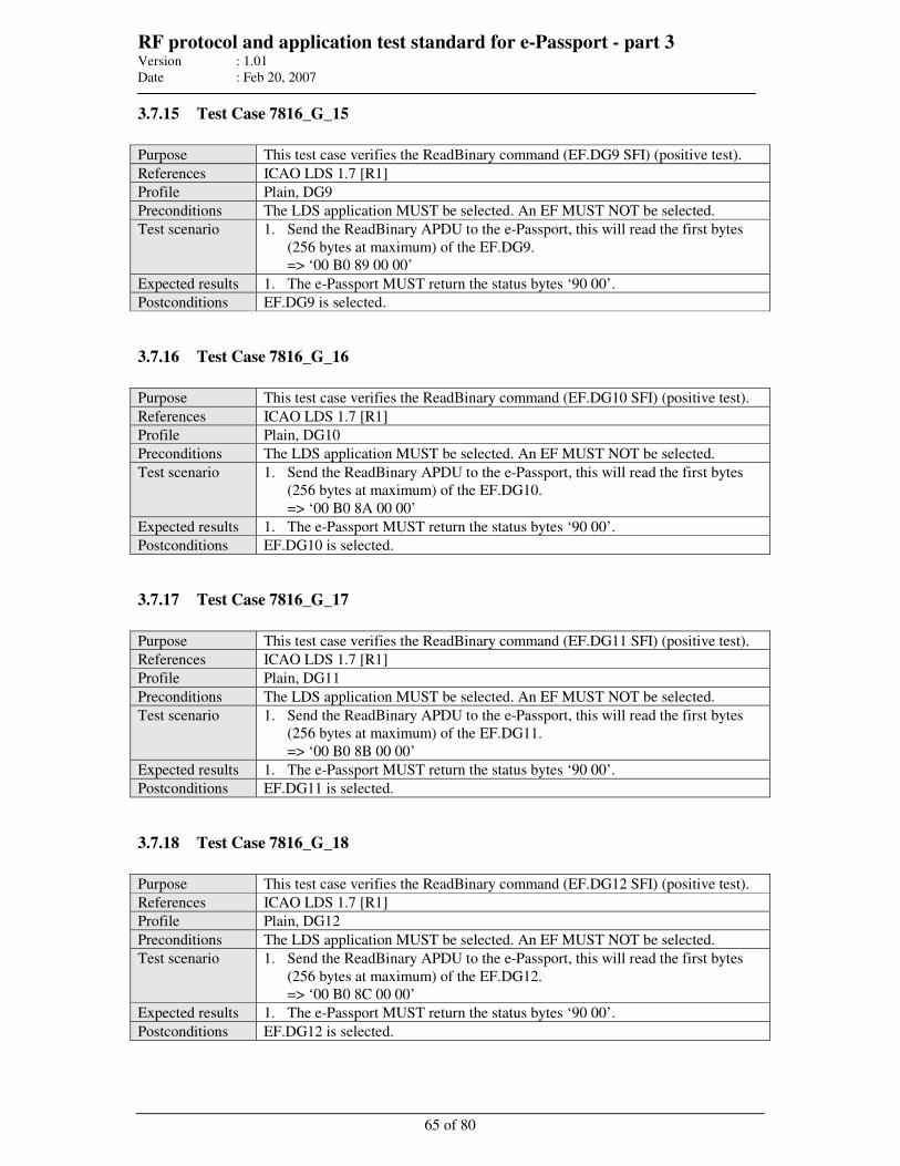
RF protocol and application test standard for e-Passport - part 3 Version : 1.01
Date : Feb 20, 2007
65 of 80
3.7.15 Test Case 7816_G_15
Purpose This test case verifies the ReadBinary command (EF.DG9 SFI) (positive test).
References ICAO LDS 1.7 [R1]
Profile Plain, DG9
Preconditions The LDS application MUST be selected. An EF MUST NOT be selected.
Test scenario 1. Send the ReadBinary APDU to the e-Passport, this will read the first bytes
(256 bytes at maximum) of the EF.DG9.
=> ‘00 B0 89 00 00’
Expected results 1. The e-Passport MUST return the status bytes ‘90 00’.
Postconditions EF.DG9 is selected.
3.7.16 Test Case 7816_G_16
Purpose This test case verifies the ReadBinary command (EF.DG10 SFI) (positive test).
References ICAO LDS 1.7 [R1]
Profile Plain, DG10
Preconditions The LDS application MUST be selected. An EF MUST NOT be selected.
Test scenario 1. Send the ReadBinary APDU to the e-Passport, this will read the first bytes
(256 bytes at maximum) of the EF.DG10.
=> ‘00 B0 8A 00 00’
Expected results 1. The e-Passport MUST return the status bytes ‘90 00’.
Postconditions EF.DG10 is selected.
3.7.17 Test Case 7816_G_17
Purpose This test case verifies the ReadBinary command (EF.DG11 SFI) (positive test).
References ICAO LDS 1.7 [R1]
Profile Plain, DG11
Preconditions The LDS application MUST be selected. An EF MUST NOT be selected.
Test scenario 1. Send the ReadBinary APDU to the e-Passport, this will read the first bytes
(256 bytes at maximum) of the EF.DG11.
=> ‘00 B0 8B 00 00’
Expected results 1. The e-Passport MUST return the status bytes ‘90 00’.
Postconditions EF.DG11 is selected.
3.7.18 Test Case 7816_G_18
Purpose This test case verifies the ReadBinary command (EF.DG12 SFI) (positive test).
References ICAO LDS 1.7 [R1]
Profile Plain, DG12
Preconditions The LDS application MUST be selected. An EF MUST NOT be selected.
Test scenario 1. Send the ReadBinary APDU to the e-Passport, this will read the first bytes
(256 bytes at maximum) of the EF.DG12.
=> ‘00 B0 8C 00 00’
Expected results 1. The e-Passport MUST return the status bytes ‘90 00’.
Postconditions EF.DG12 is selected.
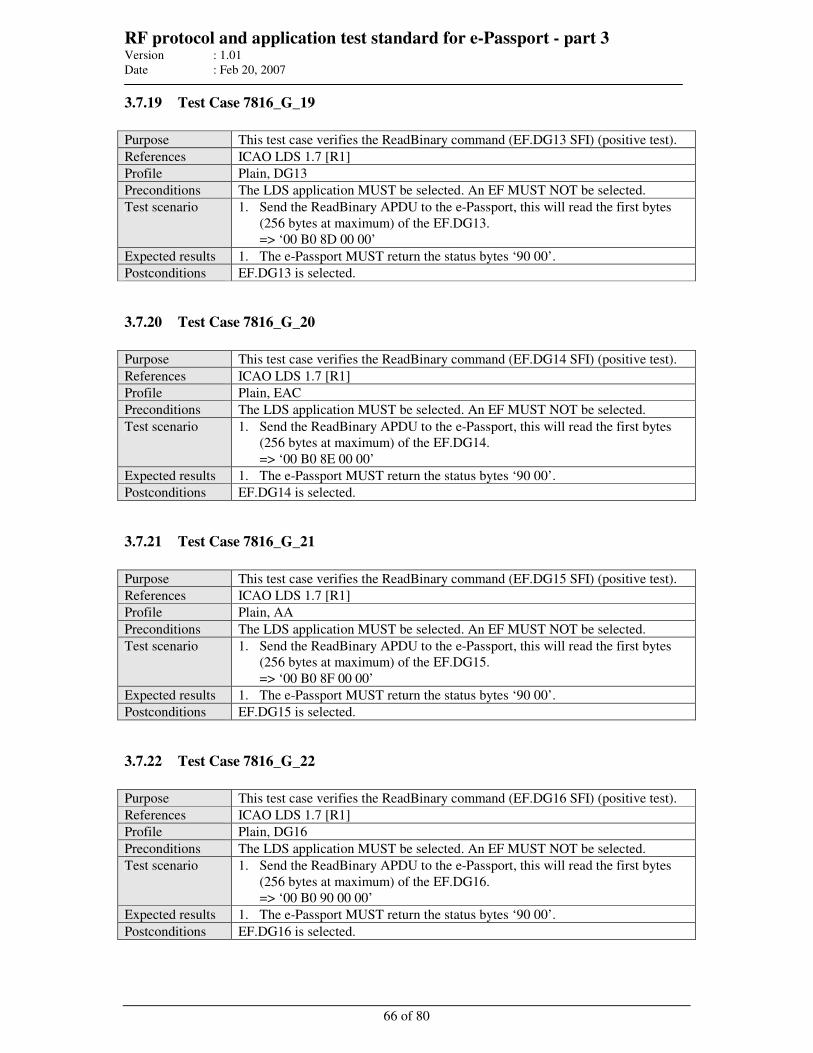
RF protocol and application test standard for e-Passport - part 3 Version : 1.01
Date : Feb 20, 2007
66 of 80
3.7.19 Test Case 7816_G_19
Purpose This test case verifies the ReadBinary command (EF.DG13 SFI) (positive test).
References ICAO LDS 1.7 [R1]
Profile Plain, DG13
Preconditions The LDS application MUST be selected. An EF MUST NOT be selected.
Test scenario 1. Send the ReadBinary APDU to the e-Passport, this will read the first bytes
(256 bytes at maximum) of the EF.DG13.
=> ‘00 B0 8D 00 00’
Expected results 1. The e-Passport MUST return the status bytes ‘90 00’.
Postconditions EF.DG13 is selected.
3.7.20 Test Case 7816_G_20
Purpose This test case verifies the ReadBinary command (EF.DG14 SFI) (positive test).
References ICAO LDS 1.7 [R1]
Profile Plain, EAC
Preconditions The LDS application MUST be selected. An EF MUST NOT be selected.
Test scenario 1. Send the ReadBinary APDU to the e-Passport, this will read the first bytes
(256 bytes at maximum) of the EF.DG14.
=> ‘00 B0 8E 00 00’
Expected results 1. The e-Passport MUST return the status bytes ‘90 00’.
Postconditions EF.DG14 is selected.
3.7.21 Test Case 7816_G_21
Purpose This test case verifies the ReadBinary command (EF.DG15 SFI) (positive test).
References ICAO LDS 1.7 [R1]
Profile Plain, AA
Preconditions The LDS application MUST be selected. An EF MUST NOT be selected.
Test scenario 1. Send the ReadBinary APDU to the e-Passport, this will read the first bytes
(256 bytes at maximum) of the EF.DG15.
=> ‘00 B0 8F 00 00’
Expected results 1. The e-Passport MUST return the status bytes ‘90 00’.
Postconditions EF.DG15 is selected.
3.7.22 Test Case 7816_G_22
Purpose This test case verifies the ReadBinary command (EF.DG16 SFI) (positive test).
References ICAO LDS 1.7 [R1]
Profile Plain, DG16
Preconditions The LDS application MUST be selected. An EF MUST NOT be selected.
Test scenario 1. Send the ReadBinary APDU to the e-Passport, this will read the first bytes
(256 bytes at maximum) of the EF.DG16.
=> ‘00 B0 90 00 00’
Expected results 1. The e-Passport MUST return the status bytes ‘90 00’.
Postconditions EF.DG16 is selected.
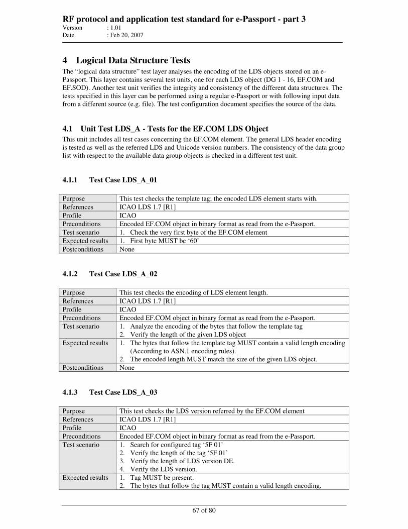
RF protocol and application test standard for e-Passport - part 3 Version : 1.01
Date : Feb 20, 2007
67 of 80
4 Logical Data Structure Tests The “logical data structure” test layer analyses the encoding of the LDS objects stored on an e-
Passport. This layer contains several test units, one for each LDS object (DG 1 - 16, EF.COM and
EF.SOD). Another test unit verifies the integrity and consistency of the different data structures. The
tests specified in this layer can be performed using a regular e-Passport or with following input data
from a different source (e.g. file). The test configuration document specifies the source of the data.
4.1 Unit Test LDS_A - Tests for the EF.COM LDS Object
This unit includes all test cases concerning the EF.COM element. The general LDS header encoding
is tested as well as the referred LDS and Unicode version numbers. The consistency of the data group
list with respect to the available data group objects is checked in a different test unit.
4.1.1 Test Case LDS_A_01
Purpose This test checks the template tag; the encoded LDS element starts with.
References ICAO LDS 1.7 [R1]
Profile ICAO
Preconditions Encoded EF.COM object in binary format as read from the e-Passport.
Test scenario 1. Check the very first byte of the EF.COM element
Expected results 1. First byte MUST be ‘60’
Postconditions None
4.1.2 Test Case LDS_A_02
Purpose This test checks the encoding of LDS element length.
References ICAO LDS 1.7 [R1]
Profile ICAO
Preconditions Encoded EF.COM object in binary format as read from the e-Passport.
Test scenario 1. Analyze the encoding of the bytes that follow the template tag
2. Verify the length of the given LDS object
Expected results 1. The bytes that follow the template tag MUST contain a valid length encoding
(According to ASN.1 encoding rules).
2. The encoded length MUST match the size of the given LDS object.
Postconditions None
4.1.3 Test Case LDS_A_03
Purpose This test checks the LDS version referred by the EF.COM element
References ICAO LDS 1.7 [R1]
Profile ICAO
Preconditions Encoded EF.COM object in binary format as read from the e-Passport.
Test scenario 1. Search for configured tag ‘5F 01’
2. Verify the length of the tag ‘5F 01’
3. Verify the length of LDS version DE.
4. Verify the LDS version.
Expected results 1. Tag MUST be present.
2. The bytes that follow the tag MUST contain a valid length encoding.
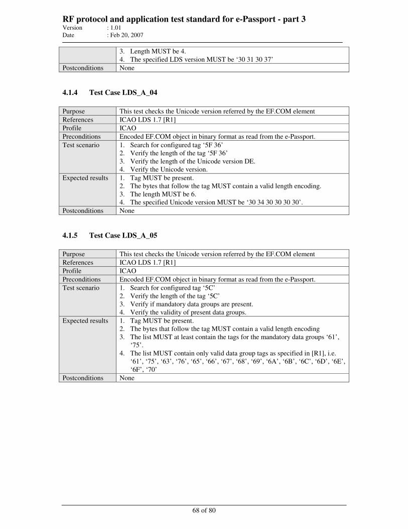
RF protocol and application test standard for e-Passport - part 3 Version : 1.01
Date : Feb 20, 2007
68 of 80
3. Length MUST be 4.
4. The specified LDS version MUST be ‘30 31 30 37’
Postconditions None
4.1.4 Test Case LDS_A_04
Purpose This test checks the Unicode version referred by the EF.COM element
References ICAO LDS 1.7 [R1]
Profile ICAO
Preconditions Encoded EF.COM object in binary format as read from the e-Passport.
Test scenario 1. Search for configured tag ‘5F 36’
2. Verify the length of the tag ‘5F 36’
3. Verify the length of the Unicode version DE.
4. Verify the Unicode version.
Expected results 1. Tag MUST be present.
2. The bytes that follow the tag MUST contain a valid length encoding.
3. The length MUST be 6.
4. The specified Unicode version MUST be ‘30 34 30 30 30 30’.
Postconditions None
4.1.5 Test Case LDS_A_05
Purpose This test checks the Unicode version referred by the EF.COM element
References ICAO LDS 1.7 [R1]
Profile ICAO
Preconditions Encoded EF.COM object in binary format as read from the e-Passport.
Test scenario 1. Search for configured tag ‘5C’
2. Verify the length of the tag ‘5C’
3. Verify if mandatory data groups are present.
4. Verify the validity of present data groups.
Expected results 1. Tag MUST be present.
2. The bytes that follow the tag MUST contain a valid length encoding
3. The list MUST at least contain the tags for the mandatory data groups ‘61’,
‘75’.
4. The list MUST contain only valid data group tags as specified in [R1], i.e.
‘61’, ‘75’, ‘63’, ‘76’, ‘65’, ‘66’, ‘67’, ‘68’, ‘69’, ‘6A’, ‘6B’, ‘6C’, ‘6D’, ‘6E’,
‘6F’, ‘70’
Postconditions None
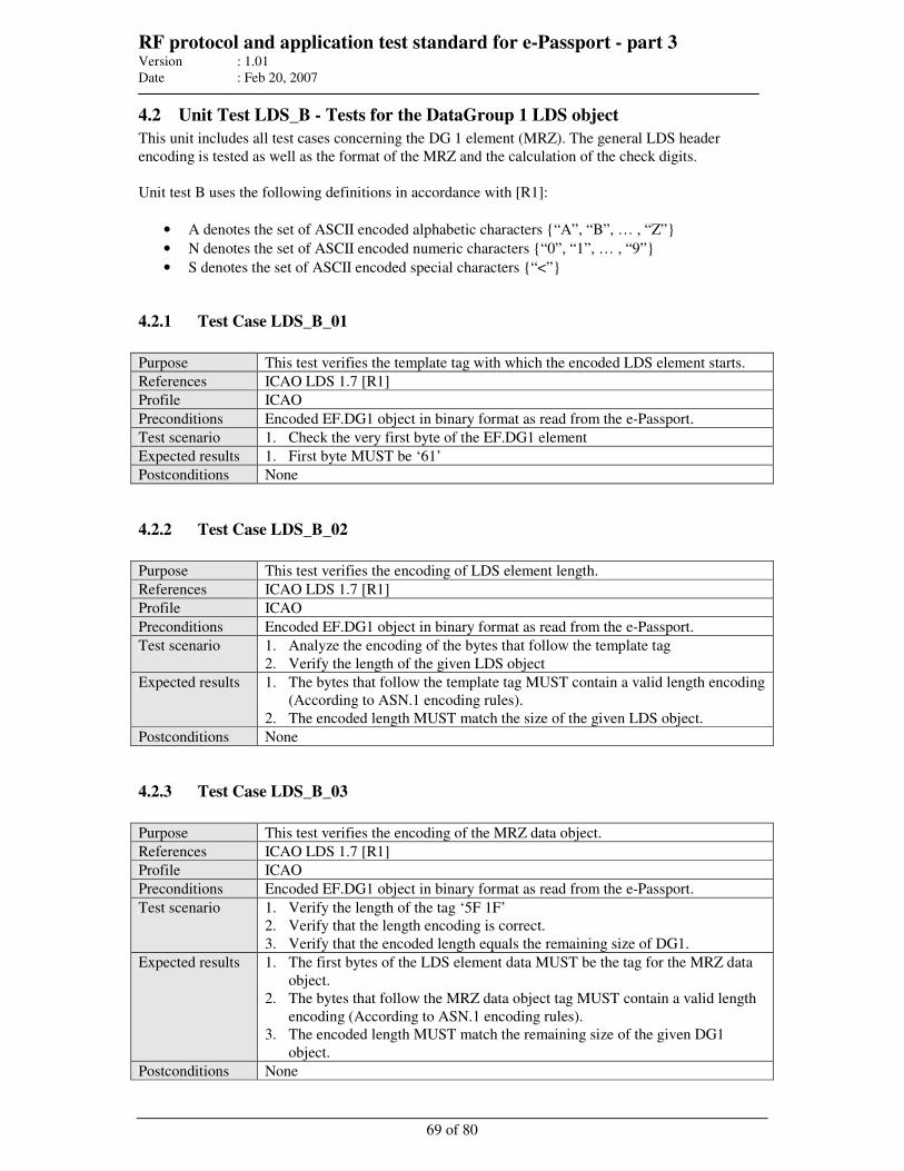
RF protocol and application test standard for e-Passport - part 3 Version : 1.01
Date : Feb 20, 2007
69 of 80
4.2 Unit Test LDS_B - Tests for the DataGroup 1 LDS object
This unit includes all test cases concerning the DG 1 element (MRZ). The general LDS header
encoding is tested as well as the format of the MRZ and the calculation of the check digits.
Unit test B uses the following definitions in accordance with [R1]:
• A denotes the set of ASCII encoded alphabetic characters “A”, “B”, … , “Z”
• N denotes the set of ASCII encoded numeric characters “0”, “1”, … , “9”
• S denotes the set of ASCII encoded special characters “<”
4.2.1 Test Case LDS_B_01
Purpose This test verifies the template tag with which the encoded LDS element starts.
References ICAO LDS 1.7 [R1]
Profile ICAO
Preconditions Encoded EF.DG1 object in binary format as read from the e-Passport.
Test scenario 1. Check the very first byte of the EF.DG1 element
Expected results 1. First byte MUST be ‘61’
Postconditions None
4.2.2 Test Case LDS_B_02
Purpose This test verifies the encoding of LDS element length.
References ICAO LDS 1.7 [R1]
Profile ICAO
Preconditions Encoded EF.DG1 object in binary format as read from the e-Passport.
Test scenario 1. Analyze the encoding of the bytes that follow the template tag
2. Verify the length of the given LDS object
Expected results 1. The bytes that follow the template tag MUST contain a valid length encoding
(According to ASN.1 encoding rules).
2. The encoded length MUST match the size of the given LDS object.
Postconditions None
4.2.3 Test Case LDS_B_03
Purpose This test verifies the encoding of the MRZ data object.
References ICAO LDS 1.7 [R1]
Profile ICAO
Preconditions Encoded EF.DG1 object in binary format as read from the e-Passport.
Test scenario 1. Verify the length of the tag ‘5F 1F’
2. Verify that the length encoding is correct.
3. Verify that the encoded length equals the remaining size of DG1.
Expected results 1. The first bytes of the LDS element data MUST be the tag for the MRZ data
object.
2. The bytes that follow the MRZ data object tag MUST contain a valid length
encoding (According to ASN.1 encoding rules).
3. The encoded length MUST match the remaining size of the given DG1
object.
Postconditions None
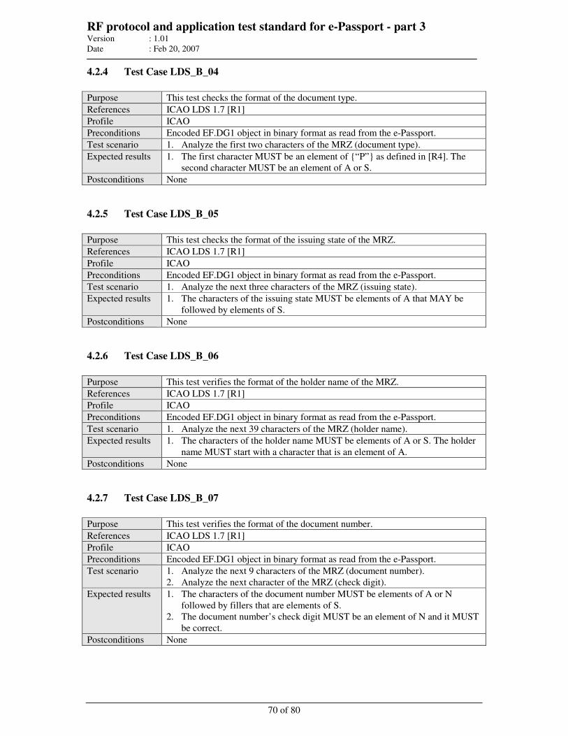
RF protocol and application test standard for e-Passport - part 3 Version : 1.01
Date : Feb 20, 2007
70 of 80
4.2.4 Test Case LDS_B_04
Purpose This test checks the format of the document type.
References ICAO LDS 1.7 [R1]
Profile ICAO
Preconditions Encoded EF.DG1 object in binary format as read from the e-Passport.
Test scenario 1. Analyze the first two characters of the MRZ (document type).
Expected results 1. The first character MUST be an element of “P” as defined in [R4]. The
second character MUST be an element of A or S.
Postconditions None
4.2.5 Test Case LDS_B_05
Purpose This test checks the format of the issuing state of the MRZ.
References ICAO LDS 1.7 [R1]
Profile ICAO
Preconditions Encoded EF.DG1 object in binary format as read from the e-Passport.
Test scenario 1. Analyze the next three characters of the MRZ (issuing state).
Expected results 1. The characters of the issuing state MUST be elements of A that MAY be
followed by elements of S.
Postconditions None
4.2.6 Test Case LDS_B_06
Purpose This test verifies the format of the holder name of the MRZ.
References ICAO LDS 1.7 [R1]
Profile ICAO
Preconditions Encoded EF.DG1 object in binary format as read from the e-Passport.
Test scenario 1. Analyze the next 39 characters of the MRZ (holder name).
Expected results 1. The characters of the holder name MUST be elements of A or S. The holder
name MUST start with a character that is an element of A.
Postconditions None
4.2.7 Test Case LDS_B_07
Purpose This test verifies the format of the document number.
References ICAO LDS 1.7 [R1]
Profile ICAO
Preconditions Encoded EF.DG1 object in binary format as read from the e-Passport.
Test scenario 1. Analyze the next 9 characters of the MRZ (document number).
2. Analyze the next character of the MRZ (check digit).
Expected results 1. The characters of the document number MUST be elements of A or N
followed by fillers that are elements of S.
2. The document number’s check digit MUST be an element of N and it MUST
be correct.
Postconditions None
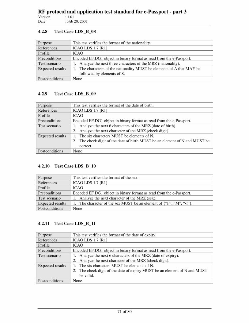
RF protocol and application test standard for e-Passport - part 3 Version : 1.01
Date : Feb 20, 2007
71 of 80
4.2.8 Test Case LDS_B_08
Purpose This test verifies the format of the nationality.
References ICAO LDS 1.7 [R1]
Profile ICAO
Preconditions Encoded EF.DG1 object in binary format as read from the e-Passport.
Test scenario 1. Analyze the next three characters of the MRZ (nationality).
Expected results 1. The characters of the nationality MUST be elements of A that MAY be
followed by elements of S.
Postconditions None
4.2.9 Test Case LDS_B_09
Purpose This test verifies the format of the date of birth.
References ICAO LDS 1.7 [R1]
Profile ICAO
Preconditions Encoded EF.DG1 object in binary format as read from the e-Passport.
Test scenario 1. Analyze the next 6 characters of the MRZ (date of birth).
2. Analyze the next character of the MRZ (check digit).
Expected results 1. The six characters MUST be elements of N.
2. The check digit of the date of birth MUST be an element of N and MUST be
correct.
Postconditions None
4.2.10 Test Case LDS_B_10
Purpose This test verifies the format of the sex.
References ICAO LDS 1.7 [R1]
Profile ICAO
Preconditions Encoded EF.DG1 object in binary format as read from the e-Passport.
Test scenario 1. Analyze the next character of the MRZ (sex).
Expected results 1. The character of the sex MUST be an element of “F”, “M”, “<”.
Postconditions None
4.2.11 Test Case LDS_B_11
Purpose This test verifies the format of the date of expiry.
References ICAO LDS 1.7 [R1]
Profile ICAO
Preconditions Encoded EF.DG1 object in binary format as read from the e-Passport.
Test scenario 1. Analyze the next 6 characters of the MRZ (date of expiry).
2. Analyze the next character of the MRZ (check digit).
Expected results 1. The six characters MUST be elements of N.
2. The check digit of the date of expiry MUST be an element of N and MUST
be valid.
Postconditions None
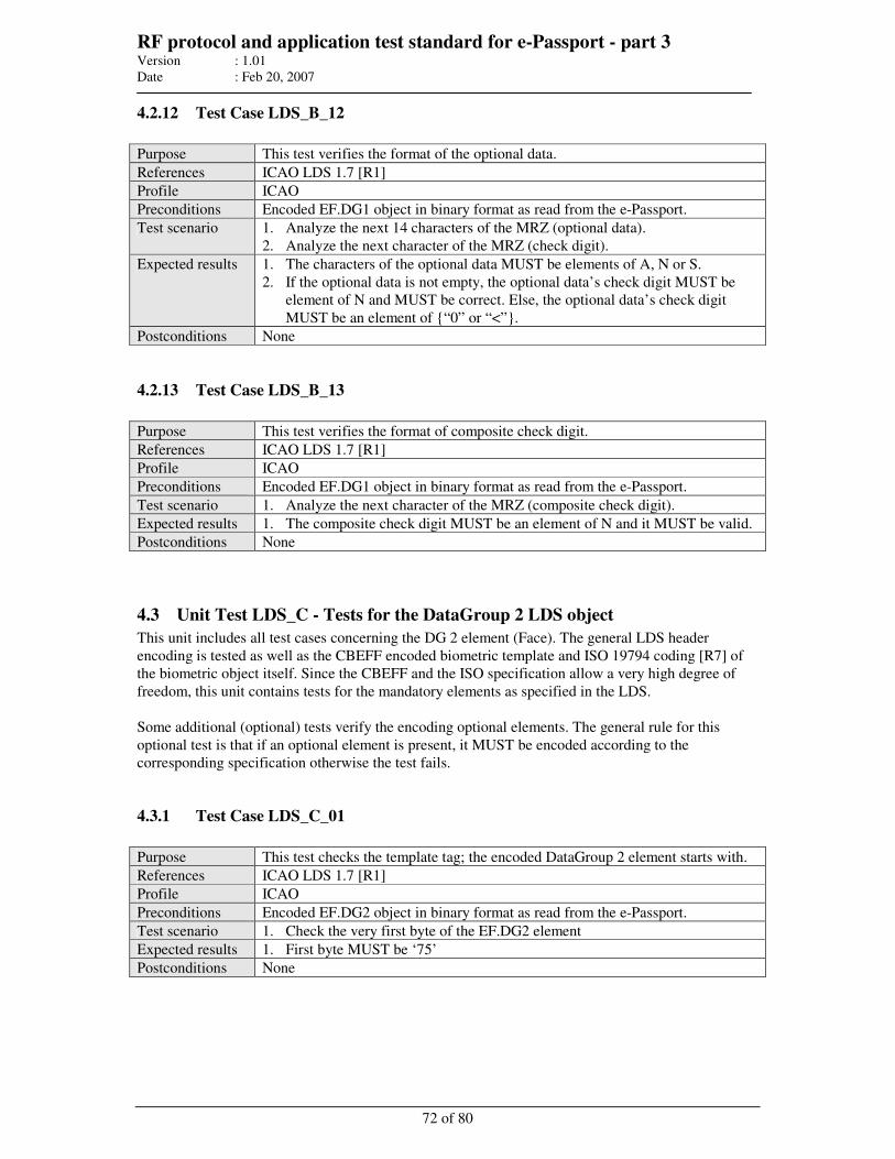
RF protocol and application test standard for e-Passport - part 3 Version : 1.01
Date : Feb 20, 2007
72 of 80
4.2.12 Test Case LDS_B_12
Purpose This test verifies the format of the optional data.
References ICAO LDS 1.7 [R1]
Profile ICAO
Preconditions Encoded EF.DG1 object in binary format as read from the e-Passport.
Test scenario 1. Analyze the next 14 characters of the MRZ (optional data).
2. Analyze the next character of the MRZ (check digit).
Expected results 1. The characters of the optional data MUST be elements of A, N or S.
2. If the optional data is not empty, the optional data’s check digit MUST be
element of N and MUST be correct. Else, the optional data’s check digit
MUST be an element of “0” or “<”.
Postconditions None
4.2.13 Test Case LDS_B_13
Purpose This test verifies the format of composite check digit.
References ICAO LDS 1.7 [R1]
Profile ICAO
Preconditions Encoded EF.DG1 object in binary format as read from the e-Passport.
Test scenario 1. Analyze the next character of the MRZ (composite check digit).
Expected results 1. The composite check digit MUST be an element of N and it MUST be valid.
Postconditions None
4.3 Unit Test LDS_C - Tests for the DataGroup 2 LDS object
This unit includes all test cases concerning the DG 2 element (Face). The general LDS header
encoding is tested as well as the CBEFF encoded biometric template and ISO 19794 coding [R7] of
the biometric object itself. Since the CBEFF and the ISO specification allow a very high degree of
freedom, this unit contains tests for the mandatory elements as specified in the LDS.
Some additional (optional) tests verify the encoding optional elements. The general rule for this
optional test is that if an optional element is present, it MUST be encoded according to the
corresponding specification otherwise the test fails.
4.3.1 Test Case LDS_C_01
Purpose This test checks the template tag; the encoded DataGroup 2 element starts with.
References ICAO LDS 1.7 [R1]
Profile ICAO
Preconditions Encoded EF.DG2 object in binary format as read from the e-Passport.
Test scenario 1. Check the very first byte of the EF.DG2 element
Expected results 1. First byte MUST be ‘75’
Postconditions None
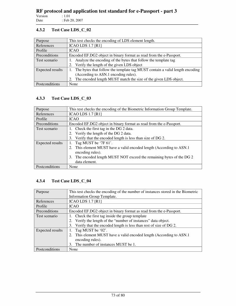
RF protocol and application test standard for e-Passport - part 3 Version : 1.01
Date : Feb 20, 2007
73 of 80
4.3.2 Test Case LDS_C_02
Purpose This test checks the encoding of LDS element length.
References ICAO LDS 1.7 [R1]
Profile ICAO
Preconditions Encoded EF.DG2 object in binary format as read from the e-Passport.
Test scenario 1. Analyze the encoding of the bytes that follow the template tag
2. Verify the length of the given LDS object
Expected results 1. The bytes that follow the template tag MUST contain a valid length encoding
(According to ASN.1 encoding rules).
2. The encoded length MUST match the size of the given LDS object.
Postconditions None
4.3.3 Test Case LDS_C_03
Purpose This test checks the encoding of the Biometric Information Group Template.
References ICAO LDS 1.7 [R1]
Profile ICAO
Preconditions Encoded EF.DG2 object in binary format as read from the e-Passport.
Test scenario 1. Check the first tag in the DG 2 data.
2. Verify the length of the DG 2 data.
3. Verify that the encoded length is less than size of DG 2.
Expected results 1. Tag MUST be ‘7F 61’.
2. This element MUST have a valid encoded length (According to ASN.1
encoding rules).
3. The encoded length MUST NOT exceed the remaining bytes of the DG 2
data element.
Postconditions None
4.3.4 Test Case LDS_C_04
Purpose This test checks the encoding of the number of instances stored in the Biometric
Information Group Template.
References ICAO LDS 1.7 [R1]
Profile ICAO
Preconditions Encoded EF.DG2 object in binary format as read from the e-Passport.
Test scenario 1. Check the first tag inside the group template
2. Verify the length of the “number of instances” data object.
3. Verify that the encoded length is less than rest of size of DG 2.
Expected results 1. Tag MUST be ‘02’.
2. This element MUST have a valid encoded length (According to ASN.1
encoding rules).
3. The number of instances MUST be 1.
Postconditions None
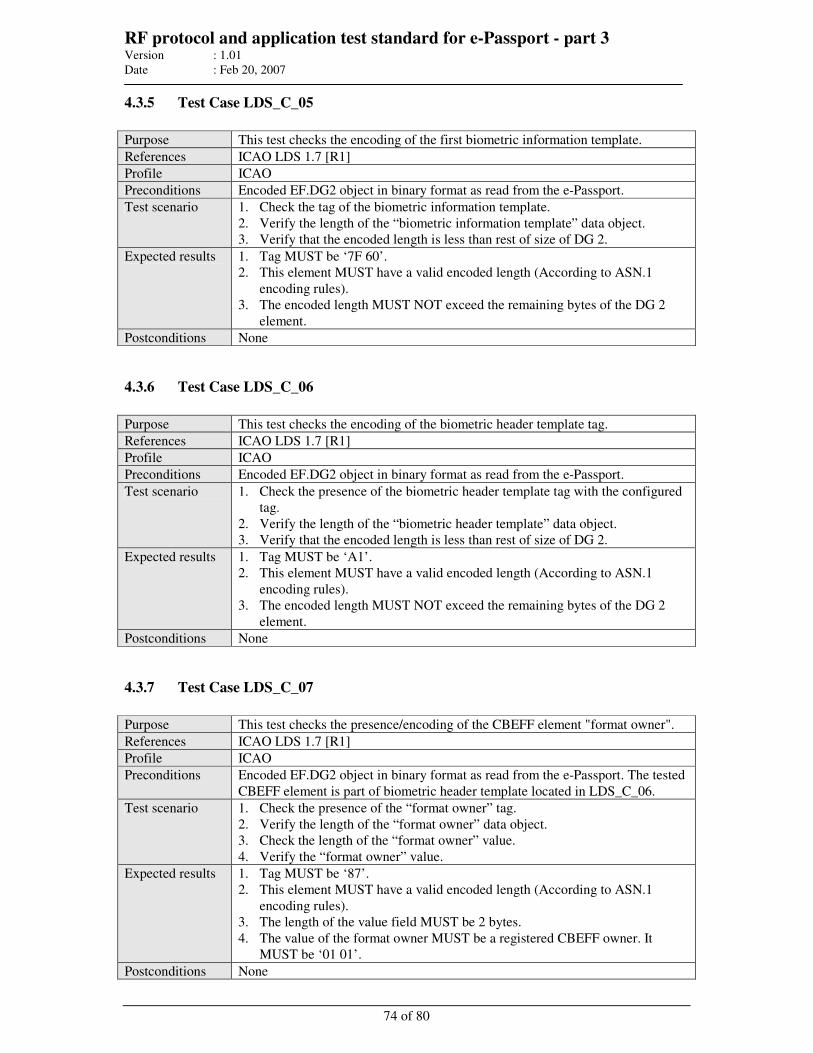
RF protocol and application test standard for e-Passport - part 3 Version : 1.01
Date : Feb 20, 2007
74 of 80
4.3.5 Test Case LDS_C_05
Purpose This test checks the encoding of the first biometric information template.
References ICAO LDS 1.7 [R1]
Profile ICAO
Preconditions Encoded EF.DG2 object in binary format as read from the e-Passport.
Test scenario 1. Check the tag of the biometric information template.
2. Verify the length of the “biometric information template” data object.
3. Verify that the encoded length is less than rest of size of DG 2.
Expected results 1. Tag MUST be ‘7F 60’.
2. This element MUST have a valid encoded length (According to ASN.1
encoding rules).
3. The encoded length MUST NOT exceed the remaining bytes of the DG 2
element.
Postconditions None
4.3.6 Test Case LDS_C_06
Purpose This test checks the encoding of the biometric header template tag.
References ICAO LDS 1.7 [R1]
Profile ICAO
Preconditions Encoded EF.DG2 object in binary format as read from the e-Passport.
Test scenario 1. Check the presence of the biometric header template tag with the configured
tag.
2. Verify the length of the “biometric header template” data object.
3. Verify that the encoded length is less than rest of size of DG 2.
Expected results 1. Tag MUST be ‘A1’.
2. This element MUST have a valid encoded length (According to ASN.1
encoding rules).
3. The encoded length MUST NOT exceed the remaining bytes of the DG 2
element.
Postconditions None
4.3.7 Test Case LDS_C_07
Purpose This test checks the presence/encoding of the CBEFF element "format owner".
References ICAO LDS 1.7 [R1]
Profile ICAO
Preconditions Encoded EF.DG2 object in binary format as read from the e-Passport. The tested
CBEFF element is part of biometric header template located in LDS_C_06.
Test scenario 1. Check the presence of the “format owner” tag.
2. Verify the length of the “format owner” data object.
3. Check the length of the “format owner” value.
4. Verify the “format owner” value.
Expected results 1. Tag MUST be ‘87’.
2. This element MUST have a valid encoded length (According to ASN.1
encoding rules).
3. The length of the value field MUST be 2 bytes.
4. The value of the format owner MUST be a registered CBEFF owner. It
MUST be ‘01 01’.
Postconditions None
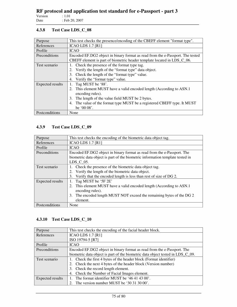
RF protocol and application test standard for e-Passport - part 3 Version : 1.01
Date : Feb 20, 2007
75 of 80
4.3.8 Test Case LDS_C_08
Purpose This test checks the presence/encoding of the CBEFF element "format type".
References ICAO LDS 1.7 [R1]
Profile ICAO
Preconditions Encoded EF.DG2 object in binary format as read from the e-Passport. The tested
CBEFF element is part of biometric header template located in LDS_C_06.
Test scenario 1. Check the presence of the format type tag.
2. Verify the length of the “format type” data object.
3. Check the length of the “format type” value.
4. Verify the “format type” value.
Expected results 1. Tag MUST be ‘88’.
2. This element MUST have a valid encoded length (According to ASN.1
encoding rules).
3. The length of the value field MUST be 2 bytes.
4. The value of the format type MUST be a registered CBEFF type. It MUST
be ‘00 08’.
Postconditions None
4.3.9 Test Case LDS_C_09
Purpose This test checks the encoding of the biometric data object tag.
References ICAO LDS 1.7 [R1]
Profile ICAO
Preconditions Encoded EF.DG2 object in binary format as read from the e-Passport. The
biometric data object is part of the biometric information template tested in
LDS_C_05.
Test scenario 1. Check the presence of the biometric data object tag.
2. Verify the length of the biometric data object.
3. Verify that the encoded length is less than rest of size of DG 2.
Expected results 1. Tag MUST be ‘5F 2E’
2. This element MUST have a valid encoded length (According to ASN.1
encoding rules).
3. The encoded length MUST NOT exceed the remaining bytes of the DG 2
element.
Postconditions None
4.3.10 Test Case LDS_C_10
Purpose This test checks the encoding of the facial header block.
References ICAO LDS 1.7 [R1]
ISO 19794-5 [R7]
Profile ICAO
Preconditions Encoded EF.DG2 object in binary format as read from the e-Passport. The
biometric data object is part of the biometric data object tested in LDS_C_09.
Test scenario 1. Check the first 4 bytes of the header block (Format identifier)
2. Check the next 4 bytes of the header block (Version number)
3. Check the record length element.
4. Check the Number of Facial Images element.
Expected results 1. The format identifier MUST be ‘46 41 43 00’.
2. The version number MUST be ‘30 31 30 00’.
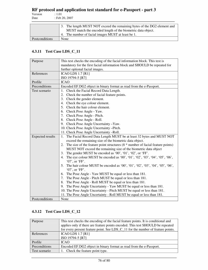
RF protocol and application test standard for e-Passport - part 3 Version : 1.01
Date : Feb 20, 2007
76 of 80
3. The length MUST NOT exceed the remaining bytes of the DG2 element and
MUST match the encoded length of the biometric data object.
4. The number of facial images MUST at least be 1.
Postconditions None
4.3.11 Test Case LDS_C_11
Purpose This test checks the encoding of the facial information block. This test is
mandatory for the first facial information block and SHOULD be repeated for
further optional facial images.
References ICAO LDS 1.7 [R1]
ISO 19794-5 [R7]
Profile ICAO
Preconditions Encoded EF.DG2 object in binary format as read from the e-Passport.
Test scenario 1. Check the Facial Record Data Length.
2. Check the number of facial feature points.
3. Check the gender element.
4. Check the eye colour element.
5. Check the hair colour element.
6. Check Pose Angle - Yaw.
7. Check Pose Angle - Pitch.
8. Check Pose Angle - Roll.
9. Check Pose Angle Uncertainty –Yaw.
10. Check Pose Angle Uncertainty –Pitch.
11. Check Pose Angle Uncertainty –Roll.
Expected results 1. The Facial Record Data Length MUST be at least 32 bytes and MUST NOT
exceed the remaining size of the biometric data object.
2. The size of the feature point structures (8 * number of facial feature points)
MUST NOT exceed the remaining size of the biometric data object
3. The gender MUST be encoded as ‘00’, ‘01’, ‘02’, or ‘FF’.
4. The eye colour MUST be encoded as ‘00’, ‘01’, ‘02’, ‘03’, ‘04’, ‘05’, ‘06’,
‘07’, or ‘FF’.
5. The hair colour MUST be encoded as ‘00’, ‘01’, ‘02’, ‘03’, ‘04’, ‘05’, ‘06’,
‘07’, or ‘FF’.
6. The Pose Angle - Yaw MUST be equal or less than 181.
7. The Pose Angle - Pitch MUST be equal or less than 181.
8. The Pose Angle - Roll MUST be equal or less than 181.
9. The Pose Angle Uncertainty - Yaw MUST be equal or less than 181.
10. The Pose Angle Uncertainty - Pitch MUST be equal or less than 181.
11. The Pose Angle Uncertainty - Roll MUST be equal or less than 181.
Postconditions None
4.3.12 Test Case LDS_C_12
Purpose This test checks the encoding of the facial feature points. It is conditional and
applies only if there are feature points encoded. This test SHOULD be repeated
for every present feature point. See LDS_C_11 for the number of feature points.
References ICAO LDS 1.7 [R1]
ISO 19794-5 [R7]
Profile ICAO
Preconditions Encoded EF.DG2 object in binary format as read from the e-Passport.
Test scenario 1. Check the feature point type.
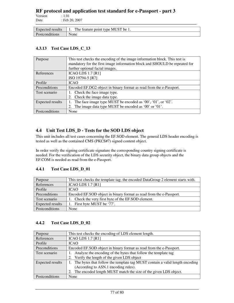
RF protocol and application test standard for e-Passport - part 3 Version : 1.01
Date : Feb 20, 2007
77 of 80
Expected results 1. The feature point type MUST be 1.
Postconditions None
4.3.13 Test Case LDS_C_13
Purpose This test checks the encoding of the image information block. This test is
mandatory for the first image information block and SHOULD be repeated for
further optional facial images.
References ICAO LDS 1.7 [R1]
ISO 19794-5 [R7]
Profile ICAO
Preconditions Encoded EF.DG2 object in binary format as read from the e-Passport.
Test scenario 1. Check the face image type.
2. Check the image data type.
Expected results 1. The face image type MUST be encoded as ‘00’, ‘01’, or ‘02’.
2. The image data type MUST be encoded as ‘00’ or ‘01’.
Postconditions None
4.4 Unit Test LDS_D - Tests for the SOD LDS object
This unit includes all test cases concerning the EF.SOD element. The general LDS header encoding is
tested as well as the contained CMS (PKCS#7) signed content object.
In order verify the signing certificate signature the corresponding country signing certificate is
needed. For the verification of the LDS security object, the binary data group objects and the
EF.COM is needed as read from the e-Passport.
4.4.1 Test Case LDS_D_01
Purpose This test checks the template tag; the encoded DataGroup 2 element starts with.
References ICAO LDS 1.7 [R1]
Profile ICAO
Preconditions Encoded EF.SOD object in binary format as read from the e-Passport.
Test scenario 1. Check the very first byte of the EF.SOD element.
Expected results 1. First byte MUST be ‘77’.
Postconditions None
4.4.2 Test Case LDS_D_02
Purpose This test checks the encoding of LDS element length.
References ICAO LDS 1.7 [R1]
Profile ICAO
Preconditions Encoded EF.SOD object in binary format as read from the e-Passport.
Test scenario 1. Analyze the encoding of the bytes that follow the template tag
2. Verify the length of the given LDS object
Expected results 1. The bytes that follow the template tag MUST contain a valid length encoding
(According to ASN.1 encoding rules).
2. The encoded length MUST match the size of the given LDS object.
Postconditions None
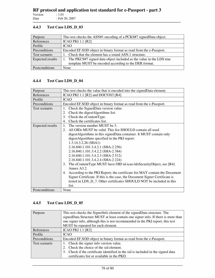
RF protocol and application test standard for e-Passport - part 3 Version : 1.01
Date : Feb 20, 2007
78 of 80
4.4.3 Test Case LDS_D_03
Purpose This test checks the ASN#1 encoding of a PCKS#7 signedData object.
References ICAO PKI 1.1 [R2]
Profile ICAO
Preconditions Encoded EF.SOD object in binary format as read from the e-Passport.
Test scenario 1. Check that the element has a sound ASN.1 structure.
Expected results 1. The PKCS#7 signed data object included as the value in the LDS true
template MUST be encoded according to the DER format.
Postconditions None
4.4.4 Test Case LDS_D_04
Purpose This test checks the value that is encoded into the signedData element.
References ICAO PKI 1.1 [R2] and DOC9303 [R4]
Profile ICAO
Preconditions Encoded EF.SOD object in binary format as read from the e-Passport.
Test scenario 1. Check the SignedData version value.
2. Check the digestAlgorithms list.
3. Check the eContentType.
4. Check the certificates list.
Expected results 1. The version number MUST be 3.
2. All OIDs MUST be valid. This list SHOULD contain all used
digestAlgorithms in this signedData container. It MUST contain only
digestAlgorithms specified in the PKI report:
1.3.14.3.2.26 (SHA1)
2.16.840.1.101.3.4.2.1 (SHA-2 256)
2.16.840.1.101.3.4.2.2 (SHA-2 384)
2.16.840.1.101.3.4.2.3 (SHA-2 512)
2.16.840.1.101.3.4.2.4 (SHA-2 224)
3. The eContentType MUST have OID id-icao-ldsSecurityObject, see [R4]
Annex A3.2.
4. According to the PKI Report; the certificate list MAY contain the Document
Signer Certificate. If this is the case, the Document Signer Certificate is
tested in LDS_D_7. Other certificates SHOULD NOT be included in this
list.
Postconditions None
4.4.5 Test Case LDS_D_05
Purpose This test checks the SignerInfo element of the signedData structure. The
signedData Structure MUST at least contain one signer info. If there is more than
one signer info, although this is not recommended in the PKI report, this test
MUST be repeated for each element.
References ICAO PKI 1.1 [R2]
Profile ICAO
Preconditions Encoded EF.SOD object in binary format as read from the e-Passport.
Test scenario 1. Check the signer info version value.
2. Check the choice of the sid element.
3. Check if the certificate identified in the sid is included in the signed data
certificates list or available in the PKD.
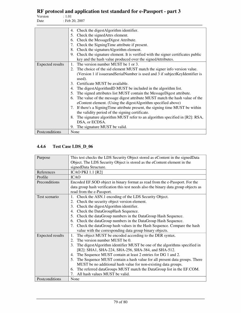
RF protocol and application test standard for e-Passport - part 3 Version : 1.01
Date : Feb 20, 2007
79 of 80
4. Check the digestAlgorithm identifier.
5. Check the signedAttrs element.
6. Check the MessageDigest Attribute.
7. Check the SigningTime attribute if present.
8. Check the signatureAlgorithm element.
9. Check the signature element. It is verified with the signer certificates public
key and the hash value produced over the signedAttributes.
Expected results 1. The version number MUST be 1 or 3.
2. The choice of the sid element MUST match the signer info version value.
(Version 1 if issuerandSerialNumber is used and 3 if subjectKeyIdentifier is
used).
3. Certificate MUST be available.
4. The digestAlgorithmID MUST be included in the algorithm list.
5. The signed attributes list MUST contain the MessageDigest attribute.
6. The value of the message digest attribute MUST match the hash value of the
eContent element. (Using the digestAlgorithm specified above)
7. If there's a SigningTime attribute present, the signing time MUST be within
the validity period of the signing certificate.
8. The signature algorithm MUST refer to an algorithm specified in [R2]: RSA,
DSA, or ECDSA.
9. The signature MUST be valid.
Postconditions None
4.4.6 Test Case LDS_D_06
Purpose This test checks the LDS Security Object stored as eContent in the signedData
Object. The LDS Security Object is stored as the eContent element in the
signedData Structure.
References ICAO PKI 1.1 [R2]
Profile ICAO
Preconditions Encoded EF.SOD object in binary format as read from the e-Passport. For the
data group hash verification this test needs also the binary data group objects as
read from the e-Passport.
Test scenario 1. Check the ASN.1 encoding of the LDS Security Object.
2. Check the security object version element.
3. Check the digestAlgorithm identifier.
4. Check the DataGroupHash Sequence.
5. Check the dataGroup numbers in the DataGroup Hash Sequence.
6. Check the dataGroup numbers in the DataGroup Hash Sequence.
7. Check the dataGroup hash values in the Hash Sequence. Compare the hash
value with the corresponding data group binary objects.
Expected results 1. The object MUST be encoded according to the DER syntax.
2. The version number MUST be 0.
3. The digestAlgorithm identifier MUST be one of the algorithms specified in
[R2]: SHA1, SHA-224, SHA-256, SHA-384, and SHA-512.
4. The Sequence MUST contain at least 2 entries for DG 1 and 2.
5. The Sequence MUST contain a hash value for all present data groups. There
MUST be no additional hash value for non-existing data groups.
6. The referred dataGroups MUST match the DataGroup list in the EF.COM.
7. All hash values MUST be valid.
Postconditions None
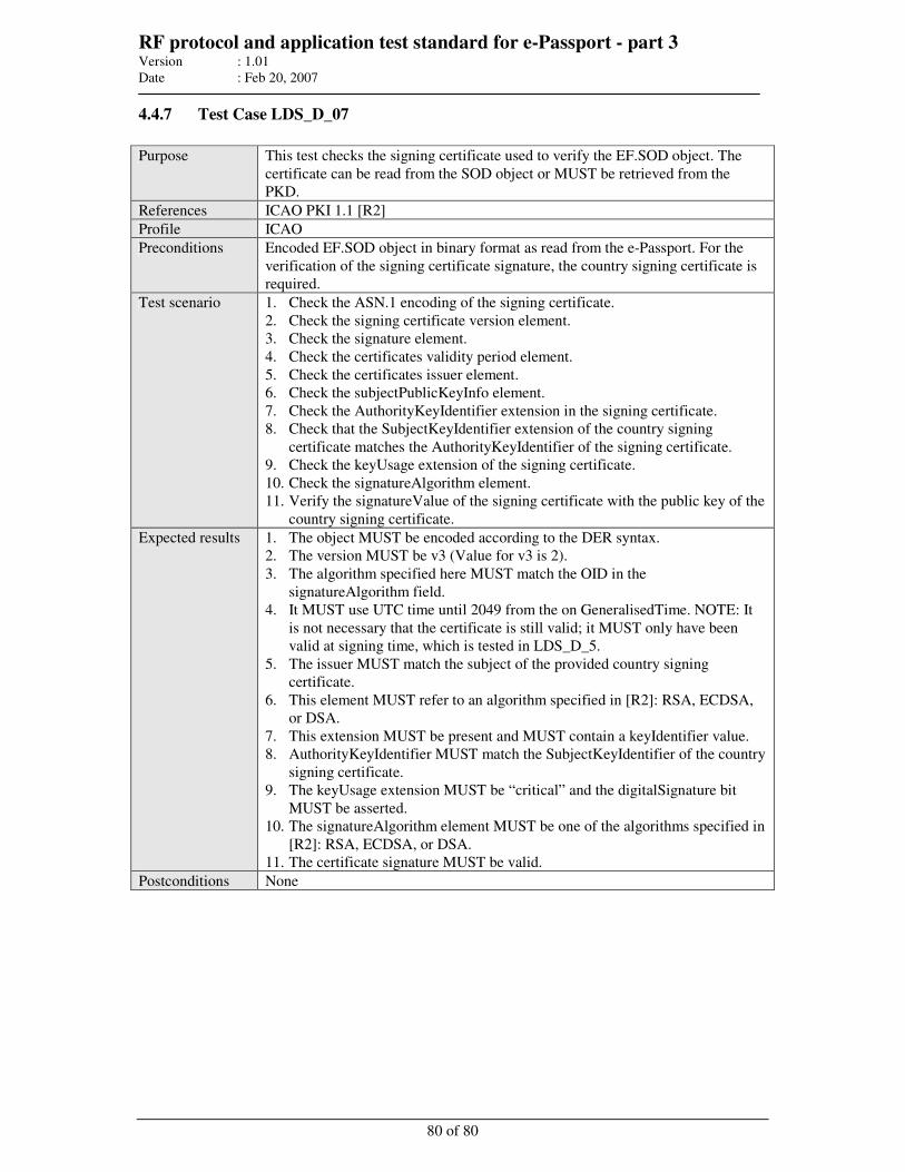
RF protocol and application test standard for e-Passport - part 3 Version : 1.01
Date : Feb 20, 2007
80 of 80
4.4.7 Test Case LDS_D_07
Purpose This test checks the signing certificate used to verify the EF.SOD object. The
certificate can be read from the SOD object or MUST be retrieved from the
PKD.
References ICAO PKI 1.1 [R2]
Profile ICAO
Preconditions Encoded EF.SOD object in binary format as read from the e-Passport. For the
verification of the signing certificate signature, the country signing certificate is
required.
Test scenario 1. Check the ASN.1 encoding of the signing certificate.
2. Check the signing certificate version element.
3. Check the signature element.
4. Check the certificates validity period element.
5. Check the certificates issuer element.
6. Check the subjectPublicKeyInfo element.
7. Check the AuthorityKeyIdentifier extension in the signing certificate.
8. Check that the SubjectKeyIdentifier extension of the country signing
certificate matches the AuthorityKeyIdentifier of the signing certificate.
9. Check the keyUsage extension of the signing certificate.
10. Check the signatureAlgorithm element.
11. Verify the signatureValue of the signing certificate with the public key of the
country signing certificate.
Expected results 1. The object MUST be encoded according to the DER syntax.
2. The version MUST be v3 (Value for v3 is 2).
3. The algorithm specified here MUST match the OID in the
signatureAlgorithm field.
4. It MUST use UTC time until 2049 from the on GeneralisedTime. NOTE: It
is not necessary that the certificate is still valid; it MUST only have been
valid at signing time, which is tested in LDS_D_5.
5. The issuer MUST match the subject of the provided country signing
certificate.
6. This element MUST refer to an algorithm specified in [R2]: RSA, ECDSA,
or DSA.
7. This extension MUST be present and MUST contain a keyIdentifier value.
8. AuthorityKeyIdentifier MUST match the SubjectKeyIdentifier of the country
signing certificate.
9. The keyUsage extension MUST be “critical” and the digitalSignature bit
MUST be asserted.
10. The signatureAlgorithm element MUST be one of the algorithms specified in
[R2]: RSA, ECDSA, or DSA.
11. The certificate signature MUST be valid.
Postconditions None
File : RF protocol Part 4 V1.01.doc
Author : ISO/JTC1/SC17/WG3/TF4 for ICAO-NTWG
MACHINE READABLE
TRAVEL DOCUMENTS
TECHNICAL REPORT
RF PROTOCOL AND APPLICATION TEST STANDARD
FOR E-PASSPORT - PART 4
E-PASSPORT READER TESTS FOR AIR INTERFACE,
INITIALISATION, ANTICOLLISION AND TRANSPORT
PROTOCOL
Version: 1.01
Date – Feb 20, 2007
Published by authority of the Secretary General
INTERNATIONAL CIVIL AVIATION ORGANIZATION
APPENDIX D
RF protocol and application test standard for e-Passport - part 4 Version : 1.01
Date : Feb 20, 2007
2 of 52
Release Control
Release Date Description
0.1 2006-02-01 First draft based on the German WG3 TF4 contribution “e-Passport Conformity
Testing” version 0.5.2 presented at TF4 meeting in Ottawa Jan 30- Feb 01, 2006
0.2 2006-05-19 Updated version based on “e-Passport Conformity Testing” PCD, layer 1-4, version
0.6, and new ICAO TR layout. Changes in chapters 3.3.1 and 3.3.2 concerning
reference SCIC.
0.3 2006-09-27 Updated version based on disposition of comments from July 14th, 2006
(resolutions of Graz meeting).
0.9 2006-11-23 Updated version based on disposition of comments from October 30th, 2006
(resolutions of Bled meeting)
1.0 2006-12-12 Final version including editorial comments from the WG8 editor meeting in Graz.
1.01 2007-02-20 Annex A and corresponding chapter 2.1 removed.
Editorial error in table 4 removed.
Release Note:
Release 2007-02-20 is the official version of the technical report by SC17 WG3
TF4 endorsed by ICAO-NTWG at the Portugal meeting. It replaces version
V1.0.
RF protocol and application test standard for e-Passport - part 4 Version : 1.01
Date : Feb 20, 2007
3 of 52
Table of contents
1 INTRODUCTION......................................................................................................................................... 5
1.1 SCOPE AND PURPOSE............................................................................................................................... 5 1.2 ASSUMPTIONS ......................................................................................................................................... 5
1.2.1 Maintenance of this TR regarding ISO standards ............................................................................. 5 1.3 TERMINOLOGY ........................................................................................................................................ 5 1.4 GLOSSARY .............................................................................................................................................. 6 1.5 ABBREVIATIONS...................................................................................................................................... 6 1.6 REFERENCE DOCUMENTATION ................................................................................................................ 8
2 GENERAL TEST REQUIREMENTS ........................................................................................................ 9
2.1 TEST ENVIRONMENT ............................................................................................................................... 9 2.1.1 Test setup ........................................................................................................................................... 9
2.2 IMPLEMENTATION CONFORMANCE STATEMENT ...................................................................................... 9 2.3 PCD TEST FEATURES............................................................................................................................. 10 2.4 NOMINAL VALUES ................................................................................................................................. 10 2.5 DEFINITION OF MEASUREMENT POINTS.................................................................................................. 10 2.6 DEFINITION OF THE REFERENCE E-PASSPORT FOR LOAD MODULATION RECEPTION TEST ....................... 11 2.7 REPORT................................................................................................................................................. 13
3 LAYER 2 TESTS ........................................................................................................................................ 14
3.1 OPERATING FIELD STRENGTH TEST (TYPES A AND B)............................................................................ 14 3.2 LOAD MODULATION RECEPTION TEST (TYPE A AND B) ......................................................................... 15 3.3 MODULATION INDEX AND WAVEFORM TEST.......................................................................................... 16
3.3.1 Type A .............................................................................................................................................. 16 3.3.2 Type B .............................................................................................................................................. 17
4 LAYER 3 TIMING AND FRAMING TESTS.......................................................................................... 19
4.1 FRAME DELAY TIME (TYPE A ONLY) ..................................................................................................... 19 4.1.1 Frame delay time SCIC to PCD....................................................................................................... 19 4.1.2 Frame delay time PCD to SCIC....................................................................................................... 19
4.2 REQUEST GUARD TIME (TYPE A ONLY) ................................................................................................. 21 4.3 BIT BOUNDARIES (TYPE B ONLY) .......................................................................................................... 21 4.4 START-OF-FRAME & END-OF-FRAME-TIMING (SOF & EOF) (TYPE B ONLY)....................................... 22 4.5 EXTRA GUARD TIME (EGT) (TYPE B ONLY).......................................................................................... 22 4.6 TIMING BEFORE SCIC START-OF-FRAME (TR0 & TR1) (TYPE B ONLY)............................................... 23 4.7 TIMING BEFORE PCD START-OF-FRAME (TR2) (TYPE B ONLY)............................................................ 24
5 LAYER 3 AND LAYER 4 PROTOCOL TESTS ..................................................................................... 25
5.1 TYPE A ACTIVATION ............................................................................................................................. 25 5.1.1 Handling of collisions...................................................................................................................... 25 5.1.2 Handling of RATS (including frame size selection) ......................................................................... 26 5.1.3 Handling of PPS .............................................................................................................................. 26 5.1.4 Handling of CID during activation.................................................................................................. 26
5.2 TYPE B ACTIVATION.............................................................................................................................. 26 5.2.1 Frame size selection......................................................................................................................... 26 5.2.2 Bit rate selection .............................................................................................................................. 27 5.2.3 Handling of CID during activation.................................................................................................. 27
5.3 HANDLING OF THE POLLING LOOP (TYPE A AND B) ............................................................................... 27 5.4 DATA EXCHANGE PROTOCOL TESTS (TYPE A AND B)............................................................................ 27
5.4.1 Error detection and recovery........................................................................................................... 28 5.4.2 Request for waiting time extension .................................................................................................. 28
ANNEX A MEASUREMENT POINTS ..................................................................................................... 29
ANNEX B COMPARISON PCD – E-PASSPORT TEST ........................................................................ 33
ANNEX C INTERFACE DEFINITION OF TM-PDUS (INFORMATIVE) .......................................... 34
RF protocol and application test standard for e-Passport - part 4 Version : 1.01
Date : Feb 20, 2007
4 of 52
C.1.1 Scope ........................................................................................................................................... 34 C.1.2 Command syntax and transportation .......................................................................................... 34
C.1.2.1 Command APDU .................................................................................................................................... 34 C.1.2.2 Response APDU ..................................................................................................................................... 35 C.1.2.3 Common return codes ............................................................................................................................. 35 C.1.2.4 Command transportation......................................................................................................................... 36
C.1.3 Commands for testing.................................................................................................................. 36 C.1.3.1 ISO 14443-2 test command..................................................................................................................... 36 C.1.3.2 Transmit pattern and receive 14443 command ....................................................................................... 37 C.1.3.3 ISO 14443-3 test command..................................................................................................................... 38 C.1.3.4 ISO 14443-4 test command..................................................................................................................... 41 C.1.3.5 Miscellaneous command......................................................................................................................... 42
ANNEX D HILBERT TRANSFORMATION (INFORMATIVE)........................................................... 44
RF protocol and application test standard for e-Passport - part 4 Version : 1.01
Date : Feb 20, 2007
5 of 52
1 Introduction
1.1 Scope and purpose
An essential element of the new ICAO compliant e-Passport is the addition of a Secure Contactless
Integrated Circuit (SCIC) that securely holds biometric data of the passport bearer within the ICAO
defined Logical Data Structure (LDS).
Successful integration of the SCIC into the e-Passport depends upon an active international
cooperation between many companies and organizations.
The e-Passport and the e-Passport reader (proximity coupling device or PCD) have been specified
and designed to operate correctly across a wide variety of infrastructures worldwide. The risk profile
for the e-Passport and the reader indicates a high impact if that design includes a widespread error or
fault. Therefore, it is essential that all companies and organizations involved make all reasonable
efforts to minimize the probability that this error or fault remains undetected before that design is
approved and e-Passports and e-Passport readers are issued.
This document defines a test plan for the contactless part of the PCD. These tests are divided into
tests of the electrical parameters, according to ISO/IEC14443-2 and tests of the initialisation &
anticollision and the frame protocol according to ISO/IEC14443-3 and -4.
In order for the PCD to operate correctly, many functional layers of technology must work together.
The purpose of this document is to define in depth the tests to be performed to minimize the
probability that an error or fault remain undetected before the design is approved.
1.2 Assumptions
1.2.1 Maintenance of this TR regarding ISO standards
This technical report is based on the currently available versions of ISO standards and amendments as
they are referenced in chapter 1.6. Based on the further development of these referenced ISO
standards and their amendments, this report will be revised by SC17/WG3/TF4.
1.3 Terminology
The key words "MUST", "SHALL", "REQUIRED", "SHOULD", "RECOMMENDED", and "MAY"
in this document are to be interpreted as described in [R3].
MUST This word, or the terms "REQUIRED" or "SHALL", mean that the definition is an
absolute requirement of the specification.
MUST NOT This phrase, or the phrase "SHALL NOT", mean that the definition is an absolute
prohibition of the specification.
SHOULD This word, or the adjective "RECOMMENDED", mean that there may exist valid
reasons in particular circumstances to ignore a particular item, but the full
implications must be understood and carefully weighed before choosing a different
course.
SHOULD NOT This phrase, or the phrase "NOT RECOMMENDED" mean that there may exist
valid reasons in particular circumstances when the particular behavior is acceptable
or even useful, but the full implications should be understood and the case carefully
weighed before implementing any behavior described with this label.
RF protocol and application test standard for e-Passport - part 4 Version : 1.01
Date : Feb 20, 2007
6 of 52
MAY This word, or the adjective "OPTIONAL", mean that an item is truly optional. One
vendor may choose to include the item because a particular marketplace requires it or
because the vendor feels that it enhances the product while another vendor may omit
the same item. An implementation which does not include a particular option MUST
be prepared to interoperate with another implementation which does include the
option, though perhaps with reduced functionality. In the same vein an
implementation which does include a particular option MUST be prepared to
interoperate with another implementation which does not include the option (except,
of course, for the feature the option provides.)
1.4 Glossary
ATTRIB Activation command used with modulation type B.
TR0 TR0 defines the guard time between the end of a PCD transmission and the start of
the SCIC subcarrier generation.
TR1
TR1 defined the synchronization time between the start of the SCIC subcarrier
generation and the start of the SCIC subcarrier modulation.
TR2 TR2 defines the synchronization time between the start of the SCIC’s EOF and the
start of the PCD’s next SOF.
Sample A sample is one piece of the total number of e-Passports required and presented for
testing according to this specification.
DUT A device under test is a sample that has been placed in the test apparatus.
Room temperature Room temperature (RT) is defined as any convenient temperature within the range of
23 °C ± 3 °C (73 °F ± 5 °F).
Modulation index The modulation index m is calculated as follows:
minlevelmaxlevel
minlevelmaxlevelm
+
−=
1.5 Abbreviations
Abbreviation
AC Anti-collision command
APDU Application protocol data unit
ATQA Answer to REQA
ATQB Answer to REQB
ATS Answer to select
CID Card identifier
DUT Device under test
EGT Extra guard time
EOF End of frame
etu Elementary time unit
fc Carrier frequency (13.56 MHz)
RF protocol and application test standard for e-Passport - part 4 Version : 1.01
Date : Feb 20, 2007
7 of 52
Abbreviation
FDT Frame delay time
fs Sub-carrier frequency (847.5 kHz)
LMA Load modulation amplitude
m Modulation index
PCD Proximity coupling device
PICC Proximity integrated circuit card
PPS Protocol and parameter selection
RATS Request for ATS
REQA Request A command
REQB Request B command
RT Room temperature
SCIC Secure contactless integrated circuit
SOF Start of frame
TM-PDU Test management protocol data unit
tr, tf Rise time, fall time
RF protocol and application test standard for e-Passport - part 4 Version : 1.01
Date : Feb 20, 2007
8 of 52
1.6 Reference documentation
The following documentation serves as a reference for this technical report:
[R1] Technical Report: Development of a Logical Data Structure – LDS for optional capacity
expansion technologies, version 1.7
[R2] Technical Report: PKI for Machine Readable Travel Documents offering ICC Read-Only
access, version 1.1
[R3] RFC 2119, S. Bradner, "Key Words for Use in RFCs to Indicate Requirement Levels", BCP
14, RFC 2119, March 1997
[R4] CD ISO/IEC 14443-1:2005, Proximity Cards: Physical Characteristics
[R5] ISO/IEC 14443-2:2001, Proximity Cards: Radio Frequency Power and Signal Interface
[R6] ISO/IEC 14443-3:2001, Proximity Cards: Initialization and Anticollision
[R7] ISO/IEC 14443-4:2001, Proximity Cards: Transmission protocol
[R8] ISO/IEC 14443-2:2001/AM1:2005, Proximity Cards: Radio Frequency Power and Signal
Interface (Amendment 2: Bit Rates of fc/64, fc/32 and fc/16)
[R9] ISO/IEC 14443-3:2001/AM1:2005, Proximity Cards: Initialization and Anticollision
(Amendment 1: Bit Rates of fc/64, fc/32 and fc/16)
[R10] ISO/IEC 10373-6:2001, Test Methods for Proximity Cards
[R11] ISO/IEC 10373-6:2001/AM1:2006, Test Methods for Proximity Cards (Amendment 1:
Protocol Test Methods for Proximity Cards)
[R12] ISO/IEC 10373-6:2001/AM2:2006, Test Methods for Proximity Cards (Amendment 2:
Improved RF Test Methods)
[R13] ISO/IEC 10373-6:2001/AM3:2006, Test Methods for Proximity Cards (Amendment 32:
Protocol test methods for proximity coupling devices)
[R14] ISO/IEC 10373-6:2001/AM4:2006, Test Methods for Proximity Cards (Amendment 4:
Additional Test Methods for PCD RF Interface and PICC Alternating Field Exposure)
[R15] ISO/IEC 10373-6:2001/AM5:2006, Test Methods for Proximity Cards (Amendment 5: Bit
Rates of fc/64, fc/32 and fc/16)
[R16] ICAO Doc 9303 Part 1 Volume 2, 6th edition, 2005.
[R17] Defect Report and Technical Corrigendum 1 for - International Standard ISO/IEC 14443-
3:2001/AM1: Identification cards – Contactless integrated circuit(s) cards – Proximity
cards – Part 3: initialization and anticollision – Amendment 1: Bit rates for fc/64, fc/32 and
fc/16
RF protocol and application test standard for e-Passport - part 4 Version : 1.01
Date : Feb 20, 2007
9 of 52
2 General test requirements
Following sub-clauses specify the different test setups, the nominal values used for the tests and a
recommendation of the report. Tests for bit rates of fc/128 and fc/32 are mandatory and SHALL be
applied. Other bit rates indicated in the PPS/ATTRIB command SHALL also be tested.
This test specification refers to the ISO/IEC standard 10373-6 and its corresponding amendments.
The PCD SHOULD support asymmetric communication speeds from/to the e-Passport if offered by
the e-Passport to minimize transaction time.
The tolerance for the resonance frequency of reference e-Passport is ± 2 %.
All given temperature values MAY have a tolerance value of ± 0.5 °C.
All other value MAY have a tolerance value as specified in the base standards.
2.1 Test environment
2.1.1 Test setup
The PCD assembly (test apparatus) that is defined in [R10] is the basis for the physical and electrical
tests. This test apparatus is used to calibrate the Reference e-Passports that are defined in [R10]
(chapter 6.3).
In addition to [R10], the samples SHALL provide the features as described in chapter 2.3. The
manufacturer provides a description how to switch the sample into the test mode and how to operate
the sample for the test cases described in this document.
2.2 Implementation conformance statement
In order to set up the tests properly, an applicant SHALL provide the information specified in Table 1
below.
Table 1: Test precondition table "Information on the product"
Information for test setup Applicant declaration
Reader class
Bit rates supported as claimed by the PPS/ATTRIB
• 106 kbit/sec
• 212 kbit/sec
• 424 kbit/sec
• 848 kbit/sec
Access control supported
• Plaintext
• Basic Access Control
• Extended Access Control
Authentication supported
• Passive Authentication
• Active Authentication
Operating temperature range
RF protocol and application test standard for e-Passport - part 4 Version : 1.01
Date : Feb 20, 2007
10 of 52
2.3 PCD test features
The test apparatus SHALL be capable of sending contiguous activation commands. For type A, these
commands are REQA, AC, SELECT, RATS, and PPS. For type B, these are REQB, the optional Slot-
MARKER and ATTRIB. If there is no response from the e-Passport, the communication type
SHOULD be changed and the activation procedure SHALL start from beginning. If this is not
possible, the dedicated commands SHALL be available to expose all commands to the upper tester.
Therefore, it is possible to start each command from host side if necessary.
Additionally the ISO/IEC 144443-4 command set SHALL be available to exchange data. It SHALL
also be possible to receive chained data, e.g. BlockExchange.
Errors SHALL be handled in the reader and not in the upper tester or host. If possible, the final
operating system SHALL be tested.
For synchronization purposes the PCD MAY provide a test pin output. The test apparatus MAY also
be synchronized by probing the backscattered signal using an ISO pickup coil. This pickup coil
MUST NOT influence the field significantly.
The applicant MAY provide the reader test interface specified in Annex C.
2.4 Nominal values
Unless otherwise specified, the following environment parameters and nominal values SHALL be
used:
Table 2: Environment parameters
Parameter Value Applies to
Environment temperature 23 °C ± 3 °C (73 °F ± 5 °F) Type A and B
Relative humidity 25 % to 75 % Type A and B
Tests have to be done as the same temperature range as the e-Passport tests (-10 °C … 50 °C). The
customer is free to specify a limited range (for example for indoor systems) in the implementation
conformance statement.
2.5 Definition of measurement points
All layer 2 tests SHALL be performed over a certain set of points within the defined volume.
Volume definition:
Annex A specifies volume dimensions, so called “reader design types”. If due to the construction
and/or normal use of the reader other dimension sizes are RECOMMENDED by the manufacturer of
the reader, the test institute SHALL check if these dimension sizes are appropriate and define the
dimensions of the volume accordingly.
Volume location:
The PCD manufacturer SHALL define the position of the volume in the technical documentation of
the PCD. The volume MUST be located with one surface exactly on the surface of the reader device.
Alternatively, the volume MAY be located within the reader. In this case, the volume size definition
MUST be adopted accordingly.
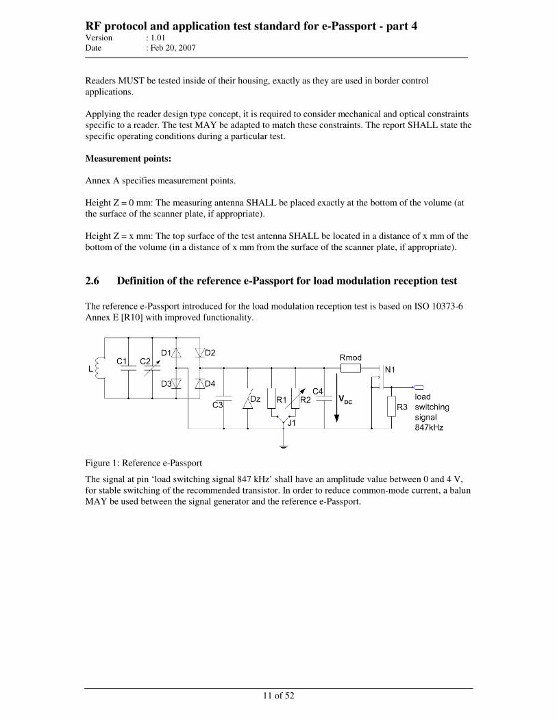
RF protocol and application test standard for e-Passport - part 4 Version : 1.01
Date : Feb 20, 2007
11 of 52
Readers MUST be tested inside of their housing, exactly as they are used in border control
applications.
Applying the reader design type concept, it is required to consider mechanical and optical constraints
specific to a reader. The test MAY be adapted to match these constraints. The report SHALL state the
specific operating conditions during a particular test.
Measurement points:
Annex A specifies measurement points.
Height Z = 0 mm: The measuring antenna SHALL be placed exactly at the bottom of the volume (at
the surface of the scanner plate, if appropriate).
Height Z = x mm: The top surface of the test antenna SHALL be located in a distance of x mm of the
bottom of the volume (in a distance of x mm from the surface of the scanner plate, if appropriate).
2.6 Definition of the reference e-Passport for load modulation reception test
The reference e-Passport introduced for the load modulation reception test is based on ISO 10373-6
Annex E [R10] with improved functionality.
Figure 1: Reference e-Passport
The signal at pin ‘load switching signal 847 kHz’ shall have an amplitude value between 0 and 4 V,
for stable switching of the recommended transistor. In order to reduce common-mode current, a balun
MAY be used between the signal generator and the reference e-Passport.
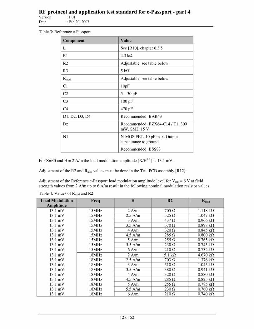
RF protocol and application test standard for e-Passport - part 4 Version : 1.01
Date : Feb 20, 2007
12 of 52
Table 3: Reference e-Passport
Component Value
L See [R10], chapter 6.3.5
R1 4.3 kΩ
R2 Adjustable, see table below
R3 5 kΩ
Rmod Adjustable, see table below
C1 10pF
C2 5 – 30 pF
C3 100 pF
C4 470 pF
D1, D2, D3, D4 Recommended: BAR43
Dz Recommended: BZX84-C14 / T1, 300
mW, SMD 15 V
N1 N-MOS FET, 10 pF max. Output
capacitance to ground.
Recommended: BSS83
For X=30 and H = 2 A/m the load modulation amplitude (X/H1.2
) is 13.1 mV.
Adjustment of the R2 and Rmod values must be done in the Test PCD assembly [R12].
Adjustment of the Reference e-Passport load modulation amplitude level for VDC = 6 V at field
strength values from 2 A/m up to 6 A/m result in the following nominal modulation resistor values.
Table 4: Values of Rmod and R2
Load Modulation Amplitude
Freq H R2 Rmod
13.1 mV 15MHz 2 A/m 705 Ω 1.118 kΩ 13.1 mV 15MHz 2.5 A/m 525 Ω 1.047 kΩ
13.1 mV 15MHz 3 A/m 437 Ω 0.966 kΩ
13.1 mV 15MHz 3.5 A/m 370 Ω 0.898 kΩ
13.1 mV 15MHz 4 A/m 320 Ω 0.845 kΩ 13.1 mV 15MHz 4.5 A/m 285 Ω 0.800 kΩ
13.1 mV 15MHz 5 A/m 255 Ω 0.765 kΩ
13.1 mV 15MHz 5.5 A/m 230 Ω 0.745 kΩ
13.1 mV 15MHz 6 A/m 210 Ω 0.732 kΩ
13.1 mV 18MHz 2 A/m 5.1 kΩ 4.670 kΩ
13.1 mV 18MHz 2.5 A/m 703 Ω 1.376 kΩ 13.1 mV 18MHz 3 A/m 510 Ω 1.045 kΩ
13.1 mV 18MHz 3.5 A/m 380 Ω 0.941 kΩ
13.1 mV 18MHz 4 A/m 320 Ω 0.880 kΩ
13.1 mV 18MHz 4.5 A/m 285 Ω 0.825 kΩ 13.1 mV 18MHz 5 A/m 255 Ω 0.785 kΩ
13.1 mV 18MHz 5.5 A/m 230 Ω 0.760 kΩ
13.1 mV 18MHz 6 A/m 210 Ω 0.740 kΩ
RF protocol and application test standard for e-Passport - part 4 Version : 1.01
Date : Feb 20, 2007
13 of 52
Notes:
• These resistor values are nominal values and SHALL be used as a guideline when adjusting
R2 and Rmod.
• VDC SHALL be measured using reference e-Passport when no 847 KHz switching signal is
applied to the probe.
2.7 Report
The test report SHALL include the number of passed tests versus the total number of tests. A
description of each test, the information if the test was pass or fail, the number of different samples
and the date of the tests SHOULD be included.
RF protocol and application test standard for e-Passport - part 4 Version : 1.01
Date : Feb 20, 2007
14 of 52
3 Layer 2 tests
3.1 Operating field strength test (Types A and B)
Test description: The purpose of this test is to check if the PCD meets the energy performance
requirements according to [R5] (chapter 6.2) and [R10] (chapter 8.1). To
include a margin of 0.5 A/m to the ISO limits, the field strength under loaded
conditions SHALL be between 2.0 A/m (1.5 + 0.5) and 7.0 A/m (7.5 - 0.5) at all
measurement positions defined in chapter 2.5. As a measurement device, the
Reference e-Passport for field and power measurements defined in [R10],
Annex D SHALL be used.
Additionally, the value of VDC SHOULD be recorded for all positions. These
values are required for the load amplitude modulation test in chapter 3.2.
For Hmin perform the following steps:
1. Adjust the resonance frequency of the Reference e-Passport to 15 MHz
as described in [R12] (8.1.2).
2. Put the Reference e-Passport into the ISO test PCD assembly.
3. Adjust the resistor R2 to get a VDC of 6 V at field strength of 2 A/m.
4. At any measurement position defined in chapter 2.5 the VDC SHALL be
greater or equal to 6 V.
For Hmax perform the following steps:
1. Adjust the resonance frequency of the Reference e-Passport to 18 MHz
as described in [R12] (8.1.2).
2. Put the Reference e-Passport into the ISO test PCD assembly.
3. Adjust the resistor R2 to get a VDC of 6 V at field strength of 7 A/m.
4. At any measurement position defined in chapter 2.5 the VDC SHALL be
less or equal to 6 V.
Modifications are done according:
• Reference: ISO/IEC 14443-2 [R5] (chapter 6.2), Operating field
strength Hmin - Hmax
• Reference: ISO/IEC 10373-6 [R10] (chapter 8.1), PCD field strength
Hmin - Hmax
Conditions: Minimum number of samples: 1
Parameters: Measurement position: As defined in chapter 2.5
Bit rate: fc/128
Temperature: -10 °C, RT, 50 °C (see restriction in chapter
2.4 “Nominal Values”)
Reference e-Passport
resonance frequency:
15 MHz, 18 MHz
Report: The test report SHALL include the number of passed tests versus the total
number of tests, a test description, and the number of different samples and the
date of the tests.
RF protocol and application test standard for e-Passport - part 4 Version : 1.01
Date : Feb 20, 2007
15 of 52
Notes:
• This test includes field strength and power measurements, see [R10] (chapter 8.1 and 8.2).
• Hmin and Hmax values are defined to keep a margin to the field strength range for the e-
Passport test.
• In addition, the tests recommended by ISO 10373-6 MAY be performed using 13.56 MHz
and 19 MHz.
3.2 Load modulation reception test (Type A and B)
An ISO Reference e-Passport for load modulation tests does not give the possibility to test the load
modulation amplitude with each PCD. In order to adapt this test, the load-switching signal SHALL be
a response to a request command and SHALL be synchronous to a request command as defined in
[R12].
Test description: The purpose of this test is to determine if the PCD is able to receive and
demodulate signals with minimum load modulation amplitude. The PCD
SHOULD provide a trigger signal (e.g. pulse at beginning or end of PCD
command) to the load switching signal source (e.g. an arbitrary waveform
generator) to send the response with required timings. The Reference e-Passport
defined in chapter 2.6 SHALL be used.
For each measurement position and resonance frequency perform the following
steps: 1. Adjust the resonance frequency of the Reference e-Passport to 15MHz
as described in [R12], chapter 8.1.2. 2. Put the Reference e-Passport into the Test PCD assembly [R12]. 3. Adjust the resistor R2 to get a VDC of 6V at H = 2 A/m field strength
according to AM4 [R14]. 4. Adjust the resistor Rmod to get the required load modulation amplitude
of 13.1 mV (for nominal resistor values see Table in chapter 2.6) 5. Put the Reference e-Passport to the measurement position defined in
chapter 2.5. 6. Adjust the distance along z axis between the Reference e-Passport and
PCD until VDC reaches 6V. 7. Check if the PCD is able to receive and demodulate a valid response
with required bit rate (see table below). 8. Repeat steps 2 to 7 where the field strength should be increased in 0.5
A/m steps up to Hmax 9. Repeat steps 1 to 8 at Reference e-Passport resonance frequency of
18MHz.
Table 5: Communication sequences
Bit rate PCD command e-Passport response
fs/128 REQ ATQ coding & framing according to
higher bit rate spec.
fs/64 REQ ATQ coding & framing according to
higher bit rate spec.
fs/32 REQ ATQ coding & framing according to
higher bit rate spec.
fs/16 REQ ATQ coding & framing according to
higher bit rate spec.
RF protocol and application test standard for e-Passport - part 4 Version : 1.01
Date : Feb 20, 2007
16 of 52
Conditions: Minimum number of samples: 1
Parameters: Measurement position: As defined in chapter 2.5
Bit rate: fc/128, fc/64, fc/32, fc/16
Temperature: -10 °C, RT, 50 °C (see restriction in chapter
2.4 “Nominal Values”)
Reference e-Passport
resonance frequency:
15 MHz, 18 MHz
Load modulation amplitude: LMAmin = 30/H1.2 mVpeak
Report: The test report SHALL include the number of passed tests versus the total
number of tests, a test description, and the number of different samples and the
date of the tests.
Note: For bit rates higher than fc/128, the ‘Transmit Pattern and Receive 14443’ command as
specified in Annex C.1.3.2 MAY be executed by the PCD.
3.3 Modulation index and waveform test
Digital amplitude demodulation SHALL be used for calculating the envelope of the modulated carrier
amplitude, e.g. Hilbert transformation. For an example program of the Hilbert transformation, see
Annex D.
3.3.1 Type A
This test shall verify if the modulated field of the PCD is complying with the described waveform
explained in [R5] (chapter 8.1) and [R8] (8.1). The parameters are rise and fall times, modulation
index, and overshoots
Modification done according:
• Reference: ISO/IEC 10373-6/Amd4 [R14](Annex I), Reference PICC for modulation index
and waveform test
• Reference: ISO/IEC 14443-2 [R5] (chapter 8.1, 9.1)
• Reference ISO/IEC 14443-2/Amd 1 [R8] (8.1, 9.1)
Test conditions for fc/128 are shown in [R5] (chapter 8.1.2), the test conditions for fc/64, fc/32, fc/16
in [R8] (8.1.2).
Test description: The purpose of this test is to determine the compliance of the PCD regarding
waveform shapes. The test SHALL show if the shapes of the modulated field is
within the defined limits. The test SHALL be performed according to [R10]
(chapter 8.3). The Reference e-Passport for modulation index and waveform test
[R14] (Annex I) SHALL be used in addition to the calibration coil. A command
with the required bit rate shall be sent by the PCD.
Adjust the resonance frequency of the Reference e-Passport to 16.5 MHz as
described in [R12] (8.1.2).
RF protocol and application test standard for e-Passport - part 4 Version : 1.01
Date : Feb 20, 2007
17 of 52
For each measurement position perform the following steps:
1. Put the Reference e-Passport into position defined in chapter 2.1.1.
2. Adjust the resistor R2 to get a VDC of 6 V at current position
3. Check if the waveform shapes are within the specified limits for all bit
rates at current position.
Conditions: Minimum number of samples: 1
Parameters: Measurement position: As defined in chapter 2.5
Bit rate: fc/128, fc/64, fc/32, fc/16
Temperature: -10 °C, RT, 50 °C (see restriction in chapter
2.4 “Nominal Values”)
Reference e-Passport
resonance frequency:
16.5 MHz
Report: The test report shall include the number of passed tests versus the total number
of tests, a test description, and the number of different samples and the date of
the tests.
Notes:
• For better interoperability, a Reference e-Passport resonance frequency of 15 MHz SHOULD
be used.
• For each bit rate, the corresponding table SHOULD be taken in account.
• For bit rates higher than fc/128, the ISO 14443-2 test command as specified in Annex C.1.3.1
MAY be executed with the PCD.
3.3.2 Type B
This test SHALL check if PCD meets the requirements concerning waveform shapes, i.e. rise and fall
times, modulation index, and overshoots.
Test description: The purpose of this test is to determine the compliance of the PCD regarding
waveform shapes (see table 36 below). The test SHALL show if the shapes of
the modulated field is within the defined limits. The test SHALL be performed
according to [R10] (chapter 8.3). The Reference e-Passport for modulation
index and waveform test [R14] (Annex I) SHALL be used in addition to the
calibration coil. A command with the required bit rate shall be sent by the
PCD.
1. Adjust the resonance frequency of the Reference PICC to 16.5 MHz as
described in [R12] (8.1.2).
For each measurement position perform the following steps:
2. Put the reference e-Passport into position defined in chapter 2.1.1.
3. Adjust the resistor R2 to get a VDC of 6 V at current position
4. Check at that position if the waveform shapes are within the specified
limits for all bit rates, as defined in table below.
The ISO 14443-2 test command as specified in Annex C.1.3.1 MAY be
executed with the PCD.
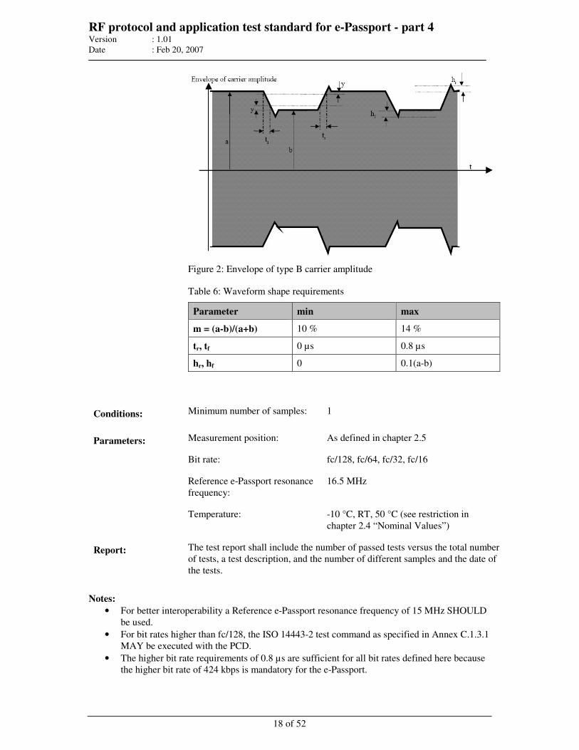
RF protocol and application test standard for e-Passport - part 4 Version : 1.01
Date : Feb 20, 2007
18 of 52
Figure 2: Envelope of type B carrier amplitude
Table 6: Waveform shape requirements
Parameter min max
m = (a-b)/(a+b) 10 % 14 %
tr, tf 0 µs 0.8 µs
hr, hf 0 0.1(a-b)
Conditions: Minimum number of samples: 1
Measurement position: As defined in chapter 2.5 Parameters:
Bit rate: fc/128, fc/64, fc/32, fc/16
Reference e-Passport resonance
frequency:
16.5 MHz
Temperature: -10 °C, RT, 50 °C (see restriction in
chapter 2.4 “Nominal Values”)
Report: The test report shall include the number of passed tests versus the total number
of tests, a test description, and the number of different samples and the date of
the tests.
Notes:
• For better interoperability a Reference e-Passport resonance frequency of 15 MHz SHOULD
be used.
• For bit rates higher than fc/128, the ISO 14443-2 test command as specified in Annex C.1.3.1
MAY be executed with the PCD.
• The higher bit rate requirements of 0.8 µs are sufficient for all bit rates defined here because
the higher bit rate of 424 kbps is mandatory for the e-Passport.
RF protocol and application test standard for e-Passport - part 4 Version : 1.01
Date : Feb 20, 2007
19 of 52
4 Layer 3 timing and framing tests All tests SHALL be performed with one specific field strength between 2 A/m and 7 A/m within the
operating volume of the PCD if not further specified.
All tests SHALL be performed at RT if not further specified.
4.1 Frame delay time (Type A only)
4.1.1 Frame delay time SCIC to PCD
This test SHALL check if the PCD can handle a FDT according to [R6]. For this test, the same setup
SHALL be used as for the load modulation reception test.
Modification done according:
• Reference: ISO/IEC 14443-3 [R6] (chapter 6.1.3), Frame delay time SCIC to PCD
Test description: This test SHALL check if a PCD command after a SCIC response is not sent
before a minimum frame delay time of 1172/fc after the SCIC has sent ATQ.
After ATQ the PCD SHALL send an AC frame.
Conditions: Minimum number of samples: 1
Parameters: Bit rate: fc/128
Report: The test report SHALL include the number of passed tests versus the total
number of tests, a test description, and the number of different samples and the
date of the tests.
Note: If possible, this test SHOULD be done for all commands, even during the protocol test.
4.1.2 Frame delay time PCD to SCIC
This test SHALL check if the PCD can handle a FDT according to [R6]. For this test, the same setup
SHALL be used as for the load modulation reception test.
Modification done according:
• Reference: ISO/IEC 14443-3 [R6] (chapter 6.1.2), Frame delay time PCD to SCIC
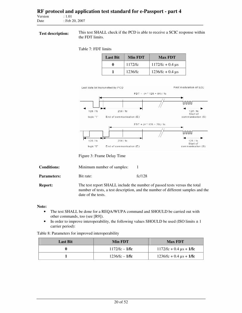
RF protocol and application test standard for e-Passport - part 4 Version : 1.01
Date : Feb 20, 2007
20 of 52
Test description: This test SHALL check if the PCD is able to receive a SCIC response within
the FDT limits.
Table 7: FDT limits
Last Bit Min FDT Max FDT
0 1172/fc 1172/fc + 0.4 µs
1 1236/fc 1236/fc + 0.4 µs
Figure 3: Frame Delay Time
Conditions: Minimum number of samples: 1
Parameters: Bit rate: fc/128
Report: The test report SHALL include the number of passed tests versus the total
number of tests, a test description, and the number of different samples and the
date of the tests.
Note:
• The test SHALL be done for a REQA/WUPA command and SHOULD be carried out with
other commands, too (see [R9]).
• In order to improve interoperability, the following values SHOULD be used (ISO limits ± 1
carrier period):
Table 8: Parameters for improved interoperability
Last Bit Min FDT Max FDT
0 1172/fc – 1/fc 1172/fc + 0.4 µs + 1/fc
1 1236/fc – 1/fc 1236/fc + 0.4 µs + 1/fc

RF protocol and application test standard for e-Passport - part 4 Version : 1.01
Date : Feb 20, 2007
21 of 52
4.2 Request guard time (Type A only)
This test SHALL check if the PCD can handle multiple REQA commands according to [R6]. For this
test, the same setup SHALL be used as for the load modulation amplitude test.
Modification done according:
• Reference: ISO/IEC 14443-3 [R6] (chapter 6.1.4), Request Guard Time
Test description: The purpose of this test is to determine the Request Guard Time of two
consecutive REQA/WUPA commands.
Conditions: Minimum number of samples: 1
Parameters: Bit rate: fc/128
Report: The test report SHALL include the number of passed tests versus the total
number of tests, a test description, and the number of different samples and the
date of the tests.
Note: This test is only relevant for PCD’s, which send consecutive REQA/WUPA.
4.3 Bit boundaries (Type B only)
Test description: The purpose of this test is to check whether the PCD meets the bit boundary
requirements according to [R9] (7.1.1).
Figure 4: Bit boundary
Conditions: Minimum number of samples: 1
Parameters: Bit rate: fc/128, fc/64, fc/32, fc/16
Report: The test report SHALL include the number of passed tests versus the total
number of tests, a test description, and the number of different samples and the
date of the tests.
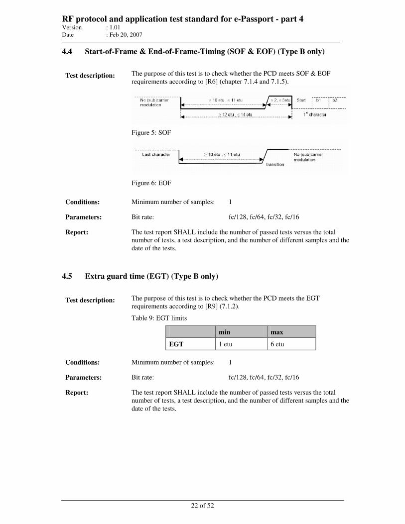
RF protocol and application test standard for e-Passport - part 4 Version : 1.01
Date : Feb 20, 2007
22 of 52
4.4 Start-of-Frame & End-of-Frame-Timing (SOF & EOF) (Type B only)
Test description: The purpose of this test is to check whether the PCD meets SOF & EOF
requirements according to [R6] (chapter 7.1.4 and 7.1.5).
Figure 5: SOF
Figure 6: EOF
Conditions: Minimum number of samples: 1
Parameters: Bit rate: fc/128, fc/64, fc/32, fc/16
Report: The test report SHALL include the number of passed tests versus the total
number of tests, a test description, and the number of different samples and the
date of the tests.
4.5 Extra guard time (EGT) (Type B only)
Test description: The purpose of this test is to check whether the PCD meets the EGT
requirements according to [R9] (7.1.2).
Table 9: EGT limits
min max
EGT 1 etu 6 etu
Conditions: Minimum number of samples: 1
Parameters: Bit rate: fc/128, fc/64, fc/32, fc/16
Report: The test report SHALL include the number of passed tests versus the total
number of tests, a test description, and the number of different samples and the
date of the tests.
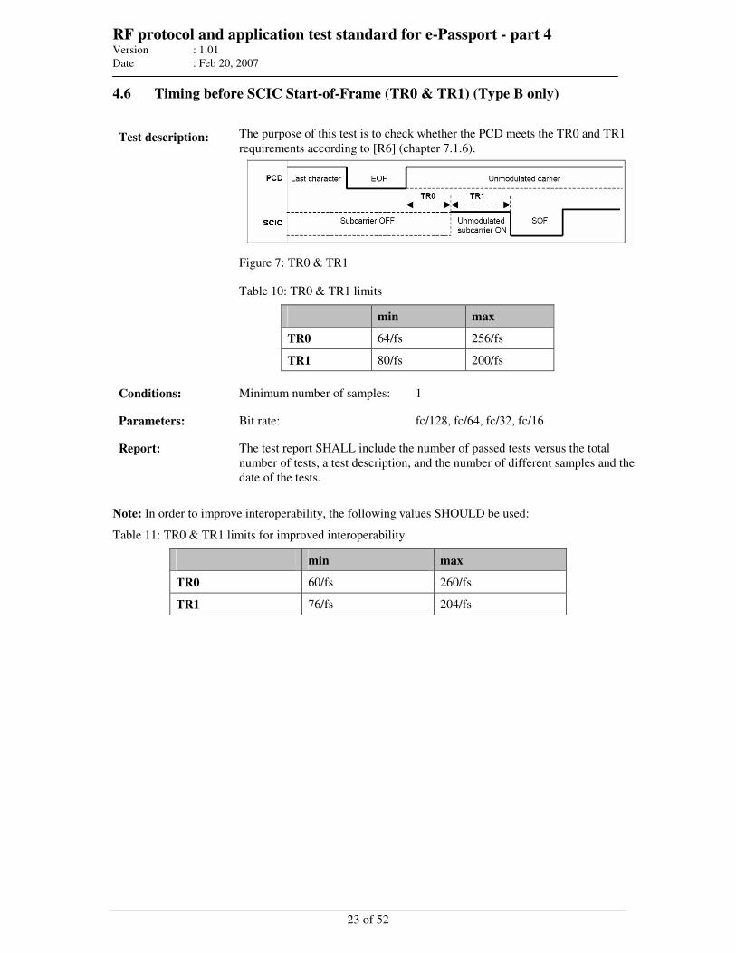
RF protocol and application test standard for e-Passport - part 4 Version : 1.01
Date : Feb 20, 2007
23 of 52
4.6 Timing before SCIC Start-of-Frame (TR0 & TR1) (Type B only)
Test description: The purpose of this test is to check whether the PCD meets the TR0 and TR1
requirements according to [R6] (chapter 7.1.6).
Figure 7: TR0 & TR1
Table 10: TR0 & TR1 limits
min max
TR0 64/fs 256/fs
TR1 80/fs 200/fs
Conditions: Minimum number of samples: 1
Parameters: Bit rate: fc/128, fc/64, fc/32, fc/16
Report: The test report SHALL include the number of passed tests versus the total
number of tests, a test description, and the number of different samples and the
date of the tests.
Note: In order to improve interoperability, the following values SHOULD be used:
Table 11: TR0 & TR1 limits for improved interoperability
min max
TR0 60/fs 260/fs
TR1 76/fs 204/fs
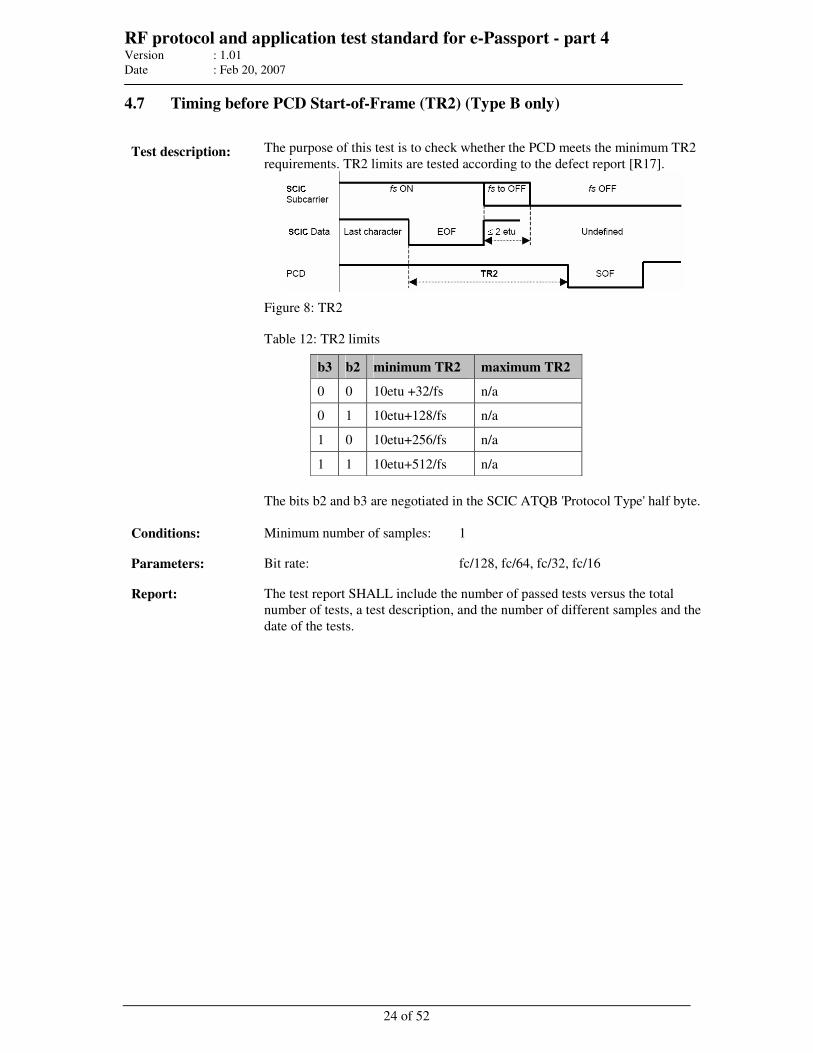
RF protocol and application test standard for e-Passport - part 4 Version : 1.01
Date : Feb 20, 2007
24 of 52
4.7 Timing before PCD Start-of-Frame (TR2) (Type B only)
Test description: The purpose of this test is to check whether the PCD meets the minimum TR2
requirements. TR2 limits are tested according to the defect report [R17].
Figure 8: TR2
Table 12: TR2 limits
b3 b2 minimum TR2 maximum TR2
0 0 10etu +32/fs n/a
0 1 10etu+128/fs n/a
1 0 10etu+256/fs n/a
1 1 10etu+512/fs n/a
The bits b2 and b3 are negotiated in the SCIC ATQB 'Protocol Type' half byte.
Conditions: Minimum number of samples: 1
Parameters: Bit rate: fc/128, fc/64, fc/32, fc/16
Report: The test report SHALL include the number of passed tests versus the total
number of tests, a test description, and the number of different samples and the
date of the tests.
RF protocol and application test standard for e-Passport - part 4 Version : 1.01
Date : Feb 20, 2007
25 of 52
5 Layer 3 and layer 4 protocol tests
These tests provide a basic set of tests to be performed to check compliance to ISO/IEC 14443
protocol layers. All tests are based on and SHALL be evaluated according to the current ISO 10373-6
standards.
For all test cases, make sure that the physical and electrical tests as mentioned in the chapters above
have passed.
Test setup:
Setup as defined for the electrical tests SHALL be used and is afterwards called “test apparatus”. All
tests SHALL be performed with one specific field strength between 2 A/m and 7 A/m within the
operating volume of the PCD if not further specified.
All tests SHALL be performed at RT if not further specified.
The test apparatus SHALL be able to emulate the protocol, to measure, monitor the timing of the
logical Input/Receive line relative to the CLK frequency, and be able to analyze the I/O-bit stream in
accordance with the protocol.
The tests are based on the ISO/IEC10373-6/Amd 3 [R13] specification. For the test commands
defined in [R13], typical commands SHOULD be used. This could be for example for
TEST_COMMAND1 the READ BINARY command. Other commands specified dependent on their
expected behaviour might also be used. The command used MAY differ between different products
and SHALL be documented in the report.
The functionality as described in clause 2.1.1 “Test setup” SHALL be used either with the final
operating system (preferred way) or with dedicated test commands.
5.1 Type A activation
These tests SHALL ensure the start-up and the activation is according to [R6] (chapter 6). These tests
are split up to collision handling, the handling of RATS and PPS, and the handling of CID during
activation.
5.1.1 Handling of collisions
Test description: The purpose of this test is to check the correct behaviour on collisions as
defined in [R6]. The tests specified in the sub-clause “Handling of bit collision
during ATQA” (chapter H.2.3) and “Handling of anticollision loop” (chapter
H.2.4) of [R13] SHOULD be used. The detailed test procedure is not specified
herein.
Report: The test report SHALL state whether the response was according to [R6]
respectively to [R13] or not. Additionally possible proprietary paths of the
“Select sequence flow chart” specified in [R6] (chapter 6.4.1) SHALL not
negatively affect the report. The report SHALL include the number of samples
tested and the date.
RF protocol and application test standard for e-Passport - part 4 Version : 1.01
Date : Feb 20, 2007
26 of 52
5.1.2 Handling of RATS (including frame size selection)
Test description: The purpose of this test is to check the correct behaviour of RATS and the
handling of ATS as defined in [R7] (chapter 5.6.1.1). The tests specified in the
sub-clause “Handling of RATS and ATS” (chapter H.2.5) and “Frame size
selection mechanism” (chapter H.2.7) of [R13] SHOULD be used. The
detailed test procedure is not specified herein.
Report: The test report SHALL state whether the response was according to [R7]
respectively to [R13] or not. The report SHALL include the number of
samples tested and the date.
5.1.3 Handling of PPS
Test description: The purpose of this test is to check the correct behaviour on handling a PPS
response as defined in [R7] (chapter 5.6.2.1). The tests specified in the sub-
clause “Handling of PPS response” (chapter H.2.6) of [R13] SHOULD be
used. The detailed test procedure is not specified herein.
Report: The test report SHALL state whether the response was according to [R7]
respectively to [R13] or not. The report SHALL include the number of
samples tested and the date.
5.1.4 Handling of CID during activation
Test description: The purpose of this test is to check the correct behaviour on handling CID
during activation as defined in [R7] (chapter 5.6.3). The tests specified in the
sub-clause “Handling of the CID during activation by PCD” [R13] (chapter
H.2.9) of SHOULD be used. The detailed test procedure is not specified
herein.
Report: The test report SHALL state whether the response was according to [R7]
respectively to [R13] or not. The report SHALL include the number of
samples tested and the date.
5.2 Type B activation
5.2.1 Frame size selection
Test description: The purpose of this test is to check the correct behaviour of the frame size
selection mechanism as defined in [R6] (chapter 7.9). The tests specified in the
sub-clause “Frame Size Selection Mechanism” (chapter H.3.2) of [R13]
SHOULD be used.
Report: The test report SHALL state whether the response was according to the
scenario defined in [R13] (chapter H.3.2). The report SHALL include the
number of samples tested and the date.
RF protocol and application test standard for e-Passport - part 4 Version : 1.01
Date : Feb 20, 2007
27 of 52
5.2.2 Bit rate selection
Test description: The purpose of this test is to check the correct behaviour of the bit rate
selection mechanism as defined in [R9]. The tests specified in [R15] (Annex
K) SHOULD be used.
Report: The test report SHALL state whether the behaviour was according to [R9]
respectively [R15]. The report SHALL include the number of samples tested
and the date.
5.2.3 Handling of CID during activation
Test description: The purpose of this test is to check the correct behaviour on handling CID
during activation as defined in [R7]. The tests specified in the sub-clause
“Handling of the CID during activation by the PCD” (chapter H.3.3) of [R13]
SHOULD be used.
Report: The test report SHALL state whether the response was according to [R7]
respectively to [R13] or not. The report SHALL include the number of
samples tested and the date.
5.3 Handling of the polling loop (Type A and B)
Test description: The purpose of this test is to check the correct behaviour during polling for
Type A and Type B SCIC’s as defined in [R6] (chapter 5). The test specified
in the sub-clause “Handling of the polling loop” of [R13] (chapter H.4.1)
SHOULD be used. The detailed test procedure is not specified herein.
Report: The test report SHALL state whether the response was according to [R6]
respectively to [R13] or not. The report SHALL include the command set used
for testing.
5.4 Data exchange protocol tests (Type A and B)
Data exchange protocol tests SHALL ensure the logical operation of the PCD is according to [R7].
These tests are valid for both, Type A, Type B whereas the activation before running these tests is
different, and listed below. All tests are based on the currently available standards.
The activation for Type A SHALL be:
1. Configuration to emulate Type A protocol
2. Activation according to [R6] (Request, Anticollision loop, Select)
3. Activation according to [R7] (RATS, optional PPS)
RF protocol and application test standard for e-Passport - part 4 Version : 1.01
Date : Feb 20, 2007
28 of 52
The activation for Type B SHALL be:
1. Configuration to emulate Type B protocol
2. Activation according to [R6] (Request, Attrib, optional Slot-marker)
5.4.1 Error detection and recovery
The purpose of this test is to check the behaviour of PCD when transmission errors occur according
to [R7] (chapter 7.5). These tests specified in [R13] cover standard communication blocks, blocks
where the PCD uses chaining and blocks where the SCIC uses chaining.
The SCIC chaining tests could be performed without knowing dedicated command behaviour on the
device under test. Any command could be divided into two parts e.g. the response to a READ
BINARY could be sent in two chained packets.
The PCD chaining is harder to achieve. If the higher layer functionality is not known in detail or a
chaining command is not used in the application these tests could not be performed. Therefore, it is
optional.
Test description: The purpose of this test is to check the behaviour of the PCD when
transmission errors occur as defined in [R7] (chapter 7.5). The test specified in
the sub-clause “Error detection and recovery” of [R13] (chapter H.4.3)
SHOULD be used. The detailed test procedure is not specified herein.
Report: The test report SHALL state whether the response was according to [R7]
respectively to [R13]. The report SHALL include the command set used for
testing.
5.4.2 Request for waiting time extension
Test description: The purpose of this test is to check the behaviour of the PCD when the SCIC
use a request for waiting time extension as defined in [R7] (chapter 7.3). The
test specified in the sub-clause “Reaction of the PCD to request for waiting
time extension” of [R13] (chapter H.4.2) SHOULD be used. The detailed test
procedure is not specified herein.
Report: The test report SHALL state whether the response was according to [R7] and
[R13]. The report SHALL include the command set used for testing.
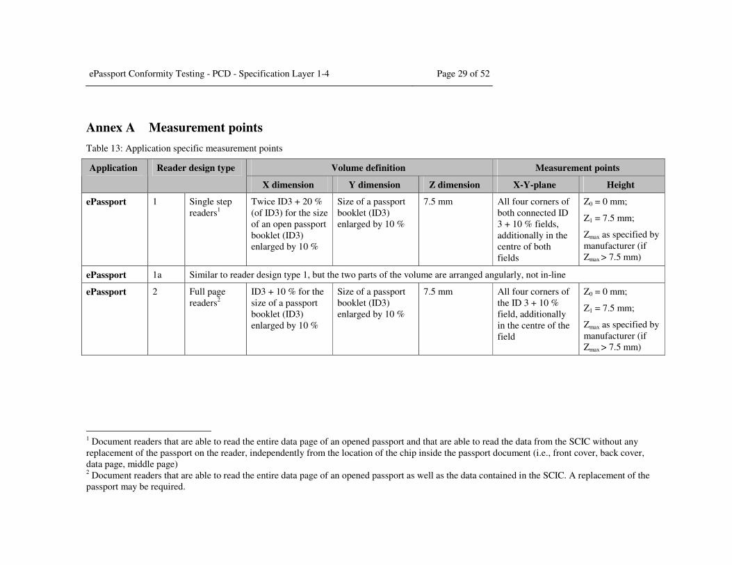
ePassport Conformity Testing - PCD - Specification Layer 1-4 Page 29 of 52
Annex A Measurement points
Table 13: Application specific measurement points
Volume definition Measurement points Application Reader design type
X dimension Y dimension Z dimension X-Y-plane Height
ePassport 1 Single step
readers1
Twice ID3 + 20 %
(of ID3) for the size
of an open passport
booklet (ID3)
enlarged by 10 %
Size of a passport
booklet (ID3)
enlarged by 10 %
7.5 mm All four corners of
both connected ID
3 + 10 % fields,
additionally in the
centre of both
fields
Z0 = 0 mm;
Z1 = 7.5 mm;
Zmax as specified by
manufacturer (if
Zmax > 7.5 mm)
ePassport 1a Similar to reader design type 1, but the two parts of the volume are arranged angularly, not in-line
ePassport 2 Full page
readers2
ID3 + 10 % for the
size of a passport
booklet (ID3)
enlarged by 10 %
Size of a passport
booklet (ID3)
enlarged by 10 %
7.5 mm All four corners of
the ID 3 + 10 %
field, additionally
in the centre of the
field
Z0 = 0 mm;
Z1 = 7.5 mm;
Zmax as specified by
manufacturer (if
Zmax > 7.5 mm)
1 Document readers that are able to read the entire data page of an opened passport and that are able to read the data from the SCIC without any
replacement of the passport on the reader, independently from the location of the chip inside the passport document (i.e., front cover, back cover,
data page, middle page) 2 Document readers that are able to read the entire data page of an opened passport as well as the data contained in the SCIC. A replacement of the
passport may be required.
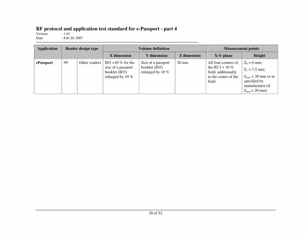
RF protocol and application test standard for e-Passport - part 4 Version : 1.01
Date : Feb 20, 2007
30 of 52
Volume definition Measurement points Application Reader design type
X dimension Y dimension Z dimension X-Y-plane Height
ePassport 99 Other readers ID3 +10 % for the
size of a passport
booklet (ID3)
enlarged by 10 %
Size of a passport
booklet (ID3)
enlarged by 10 %
20 mm All four corners of
the ID 3 + 10 %
field, additionally
in the centre of the
field
Z0 = 0 mm;
Z1 = 7.5 mm;
Zmax = 20 mm or as
specified by
manufacturer (if
Zmax > 20 mm)
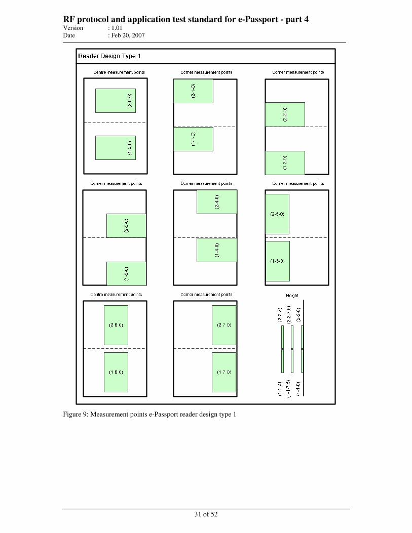
RF protocol and application test standard for e-Passport - part 4 Version : 1.01
Date : Feb 20, 2007
31 of 52
Figure 9: Measurement points e-Passport reader design type 1
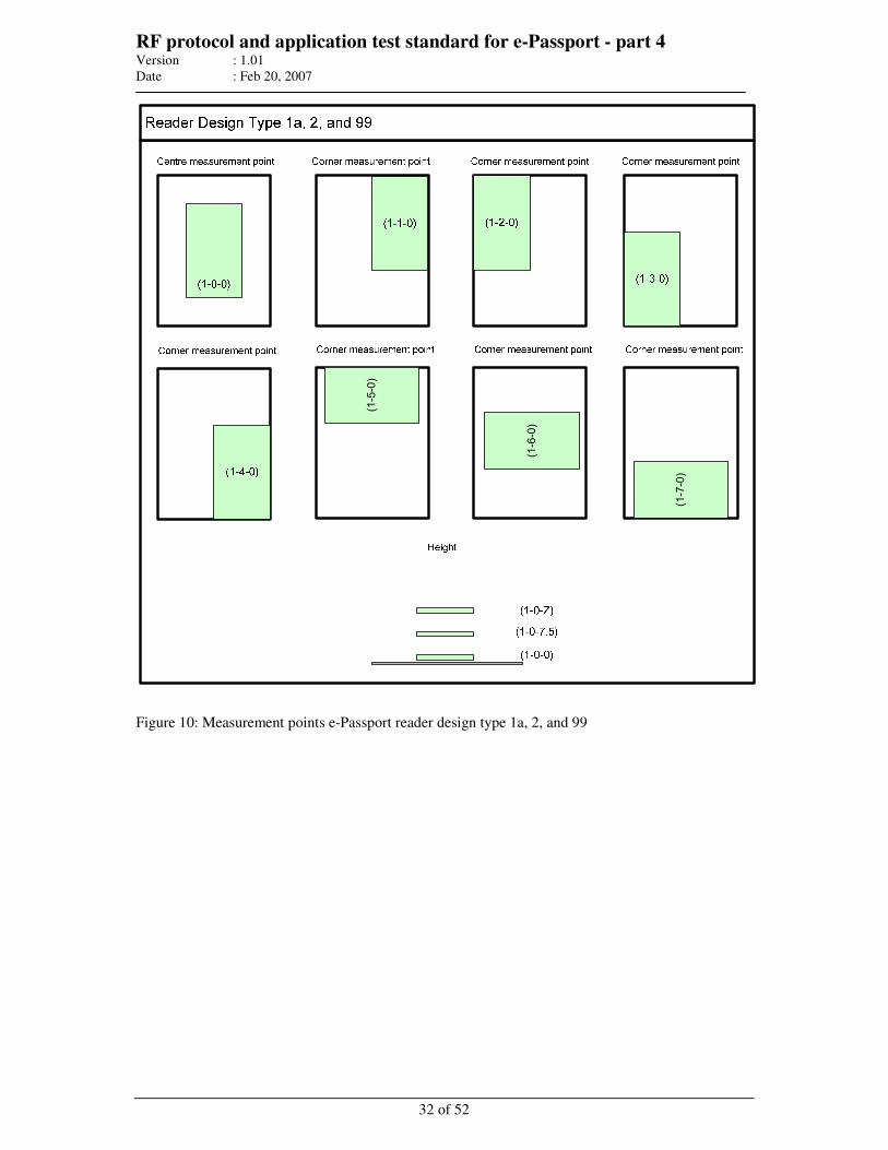
RF protocol and application test standard for e-Passport - part 4 Version : 1.01
Date : Feb 20, 2007
32 of 52
(1-7-0)
(1-6-0)
(1-5-0)
Figure 10: Measurement points e-Passport reader design type 1a, 2, and 99
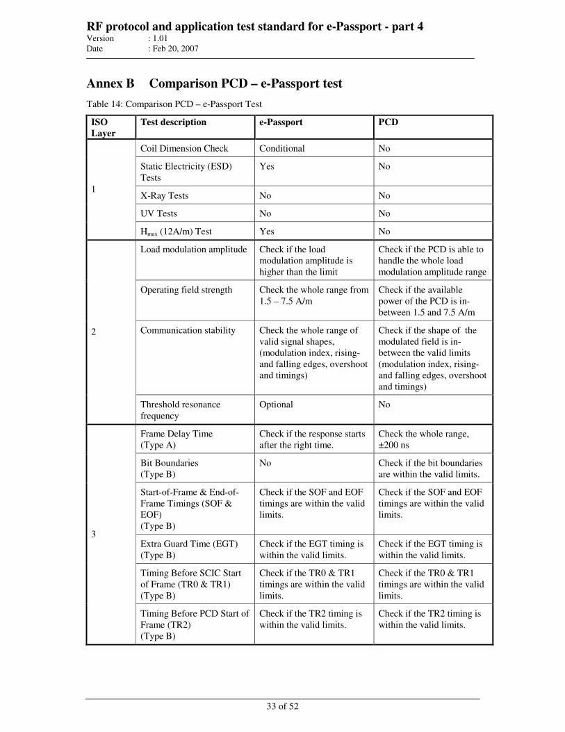
RF protocol and application test standard for e-Passport - part 4 Version : 1.01
Date : Feb 20, 2007
33 of 52
Annex B Comparison PCD – e-Passport test
Table 14: Comparison PCD – e-Passport Test
ISO
Layer
Test description e-Passport PCD
Coil Dimension Check Conditional No
Static Electricity (ESD)
Tests
Yes No
X-Ray Tests No No
UV Tests No No
1
Hmax (12A/m) Test Yes No
Load modulation amplitude Check if the load
modulation amplitude is
higher than the limit
Check if the PCD is able to
handle the whole load
modulation amplitude range
Operating field strength Check the whole range from
1.5 – 7.5 A/m
Check if the available
power of the PCD is in-
between 1.5 and 7.5 A/m
Communication stability Check the whole range of
valid signal shapes,
(modulation index, rising-
and falling edges, overshoot
and timings)
Check if the shape of the
modulated field is in-
between the valid limits
(modulation index, rising-
and falling edges, overshoot
and timings)
2
Threshold resonance
frequency
Optional No
Frame Delay Time
(Type A)
Check if the response starts
after the right time.
Check the whole range,
±200 ns
Bit Boundaries
(Type B)
No Check if the bit boundaries
are within the valid limits.
Start-of-Frame & End-of-
Frame Timings (SOF &
EOF)
(Type B)
Check if the SOF and EOF
timings are within the valid
limits.
Check if the SOF and EOF
timings are within the valid
limits.
Extra Guard Time (EGT)
(Type B)
Check if the EGT timing is
within the valid limits.
Check if the EGT timing is
within the valid limits.
Timing Before SCIC Start
of Frame (TR0 & TR1)
(Type B)
Check if the TR0 & TR1
timings are within the valid
limits.
Check if the TR0 & TR1
timings are within the valid
limits.
3
Timing Before PCD Start of
Frame (TR2)
(Type B)
Check if the TR2 timing is
within the valid limits.
Check if the TR2 timing is
within the valid limits.
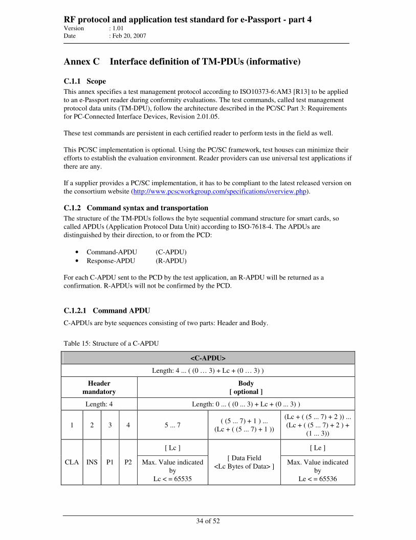
RF protocol and application test standard for e-Passport - part 4 Version : 1.01
Date : Feb 20, 2007
34 of 52
Annex C Interface definition of TM-PDUs (informative)
C.1.1 Scope
This annex specifies a test management protocol according to ISO10373-6:AM3 [R13] to be applied
to an e-Passport reader during conformity evaluations. The test commands, called test management
protocol data units (TM-DPU), follow the architecture described in the PC/SC Part 3: Requirements
for PC-Connected Interface Devices, Revision 2.01.05.
These test commands are persistent in each certified reader to perform tests in the field as well.
This PC/SC implementation is optional. Using the PC/SC framework, test houses can minimize their
efforts to establish the evaluation environment. Reader providers can use universal test applications if
there are any.
If a supplier provides a PC/SC implementation, it has to be compliant to the latest released version on
the consortium website (http://www.pcscworkgroup.com/specifications/overview.php).
C.1.2 Command syntax and transportation
The structure of the TM-PDUs follows the byte sequential command structure for smart cards, so
called APDUs (Application Protocol Data Unit) according to ISO-7618-4. The APDUs are
distinguished by their direction, to or from the PCD:
• Command-APDU (C-APDU)
• Response-APDU (R-APDU)
For each C-APDU sent to the PCD by the test application, an R-APDU will be returned as a
confirmation. R-APDUs will not be confirmed by the PCD.
C.1.2.1 Command APDU
C-APDUs are byte sequences consisting of two parts: Header and Body.
Table 15: Structure of a C-APDU
<C-APDU>
Length: 4 ... ( (0 … 3) + Lc + (0 … 3) )
Header
mandatory
Body
[ optional ]
Length: 4 Length: 0 ... ( (0 ... 3) + Lc + (0 ... 3) )
1 2 3 4 5 ... 7 ( (5 ... 7) + 1 ) ...
(Lc + ( (5 ... 7) + 1 ))
(Lc + ( (5 ... 7) + 2 )) ...
(Lc + ( (5 ... 7) + 2 ) +
(1 ... 3))
[ Lc ] [ Le ]
CLA INS P1 P2 Max. Value indicated
by
Lc < = 65535
[ Data Field
<Lc Bytes of Data> ] Max. Value indicated
by
Le < = 65536
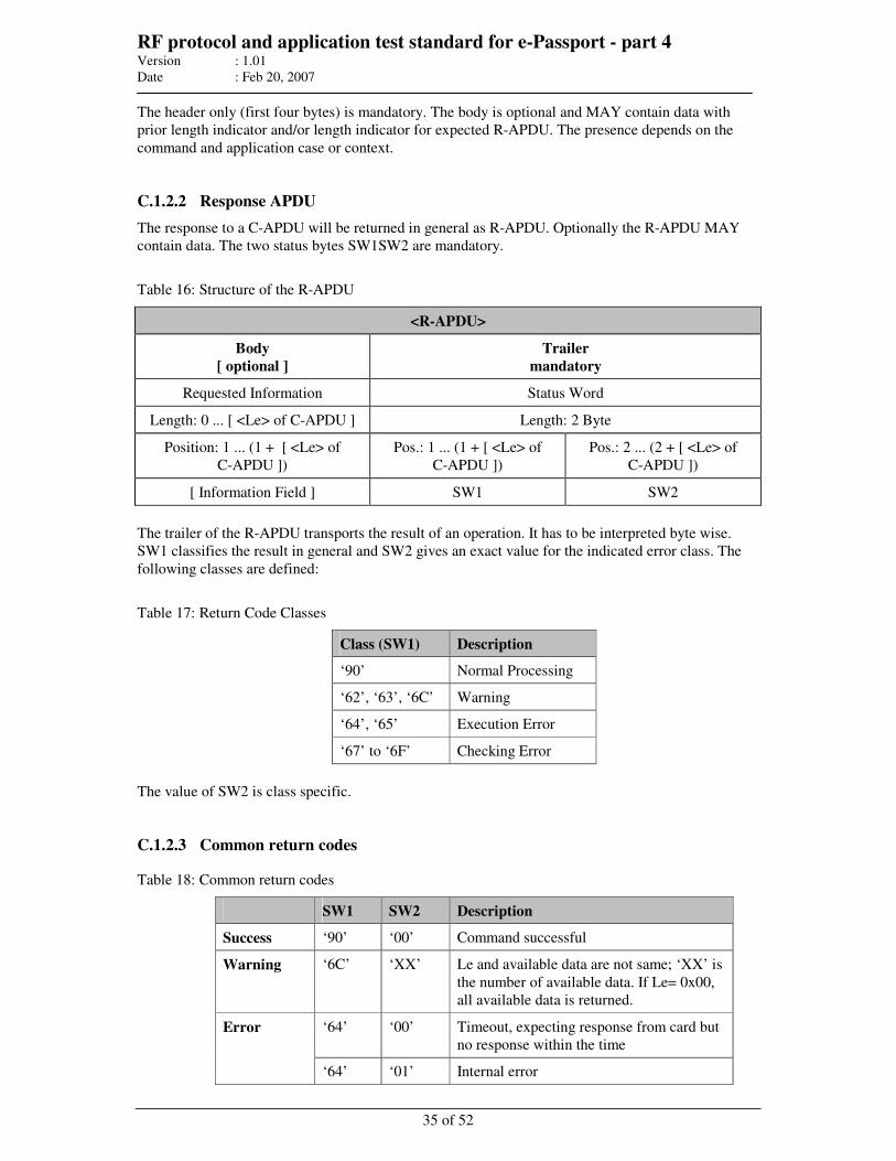
RF protocol and application test standard for e-Passport - part 4 Version : 1.01
Date : Feb 20, 2007
35 of 52
The header only (first four bytes) is mandatory. The body is optional and MAY contain data with
prior length indicator and/or length indicator for expected R-APDU. The presence depends on the
command and application case or context.
C.1.2.2 Response APDU
The response to a C-APDU will be returned in general as R-APDU. Optionally the R-APDU MAY
contain data. The two status bytes SW1SW2 are mandatory.
Table 16: Structure of the R-APDU
<R-APDU>
Body
[ optional ]
Trailer
mandatory
Requested Information Status Word
Length: 0 ... [ <Le> of C-APDU ] Length: 2 Byte
Position: 1 ... (1 + [ <Le> of
C-APDU ])
Pos.: 1 ... (1 + [ <Le> of
C-APDU ])
Pos.: 2 ... (2 + [ <Le> of
C-APDU ])
[ Information Field ] SW1 SW2
The trailer of the R-APDU transports the result of an operation. It has to be interpreted byte wise.
SW1 classifies the result in general and SW2 gives an exact value for the indicated error class. The
following classes are defined:
Table 17: Return Code Classes
Class (SW1) Description
‘90’ Normal Processing
‘62’, ‘63’, ‘6C’ Warning
‘64’, ‘65’ Execution Error
‘67’ to ‘6F’ Checking Error
The value of SW2 is class specific.
C.1.2.3 Common return codes
Table 18: Common return codes
SW1 SW2 Description
Success ‘90’ ‘00’ Command successful
Warning ‘6C’ ‘XX’ Le and available data are not same; ‘XX’ is
the number of available data. If Le= 0x00,
all available data is returned.
‘64’ ‘00’ Timeout, expecting response from card but
no response within the time
Error
‘64’ ‘01’ Internal error
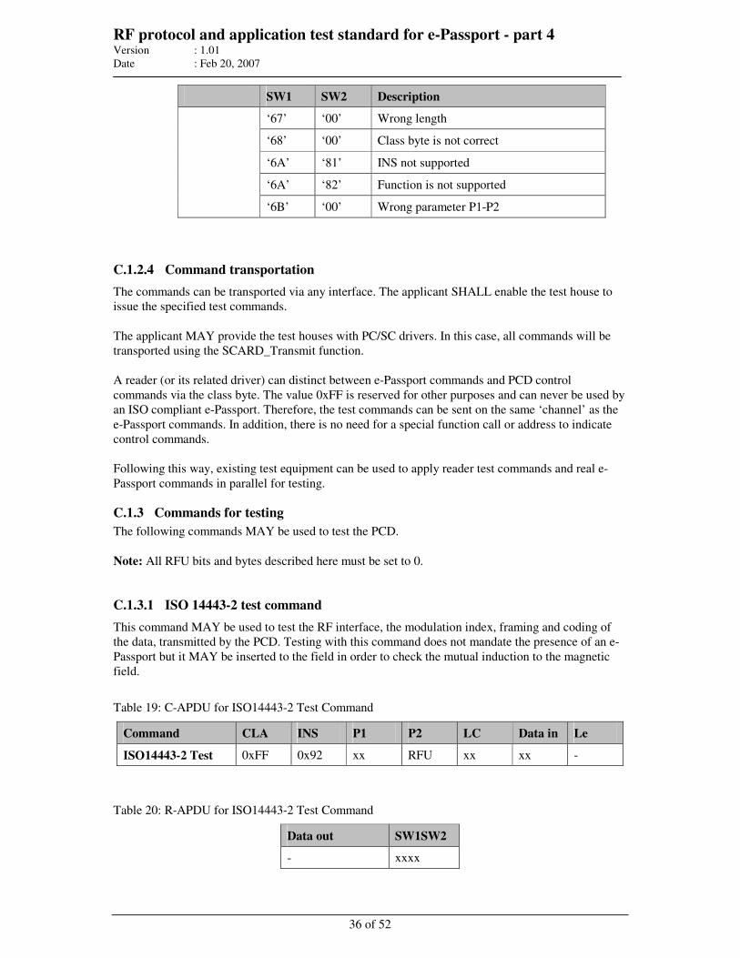
RF protocol and application test standard for e-Passport - part 4 Version : 1.01
Date : Feb 20, 2007
36 of 52
SW1 SW2 Description
‘67’ ‘00’ Wrong length
‘68’ ‘00’ Class byte is not correct
‘6A’ ‘81’ INS not supported
‘6A’ ‘82’ Function is not supported
‘6B’ ‘00’ Wrong parameter P1-P2
C.1.2.4 Command transportation
The commands can be transported via any interface. The applicant SHALL enable the test house to
issue the specified test commands.
The applicant MAY provide the test houses with PC/SC drivers. In this case, all commands will be
transported using the SCARD_Transmit function.
A reader (or its related driver) can distinct between e-Passport commands and PCD control
commands via the class byte. The value 0xFF is reserved for other purposes and can never be used by
an ISO compliant e-Passport. Therefore, the test commands can be sent on the same ‘channel’ as the
e-Passport commands. In addition, there is no need for a special function call or address to indicate
control commands.
Following this way, existing test equipment can be used to apply reader test commands and real e-
Passport commands in parallel for testing.
C.1.3 Commands for testing
The following commands MAY be used to test the PCD.
Note: All RFU bits and bytes described here must be set to 0.
C.1.3.1 ISO 14443-2 test command
This command MAY be used to test the RF interface, the modulation index, framing and coding of
the data, transmitted by the PCD. Testing with this command does not mandate the presence of an e-
Passport but it MAY be inserted to the field in order to check the mutual induction to the magnetic
field.
Table 19: C-APDU for ISO14443-2 Test Command
Command CLA INS P1 P2 LC Data in Le
ISO14443-2 Test 0xFF 0x92 xx RFU xx xx -
Table 20: R-APDU for ISO14443-2 Test Command
Data out SW1SW2
- xxxx
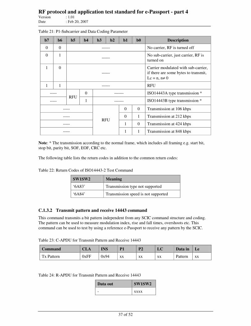
RF protocol and application test standard for e-Passport - part 4 Version : 1.01
Date : Feb 20, 2007
37 of 52
Table 21: P1-Subcarrier and Data Coding Parameter
b7 b6 b5 b4 b3 b2 b1 b0 Description
0 0 ------ No carrier, RF is turned off
0 1 ------
No sub-carrier, just carrier, RF is
turned on
1 0
------
Carrier modulated with sub-carrier,
if there are some bytes to transmit,
Lc = n, n≠ 0
1 1 ------ RFU
----- 0 ------- ISO14443A type transmission *
----- RFU
1 ------- ISO14443B type transmission *
----- 0 0 Transmission at 106 kbps
----- 0 1 Transmission at 212 kbps
----- 1 0 Transmission at 424 kbps
-----
RFU
1 1 Transmission at 848 kbps
Note: * The transmission according to the normal frame, which includes all framing e.g. start bit,
stop bit, parity bit, SOF, EOF, CRC etc.
The following table lists the return codes in addition to the common return codes:
Table 22: Return Codes of ISO14443-2 Test Command
SW1SW2 Meaning
‘6A83’ Transmission type not supported
‘6A84’ Transmission speed is not supported
C.1.3.2 Transmit pattern and receive 14443 command
This command transmits a bit pattern independent from any SCIC command structure and coding.
The pattern can be used to measure modulation index, rise and fall times, overshoots etc. This
command can be used to test by using a reference e-Passport to receive any pattern by the SCIC.
Table 23: C-APDU for Transmit Pattern and Receive 14443
Command CLA INS P1 P2 LC Data in Le
Tx Pattern 0xFF 0x94 xx xx xx Pattern xx
Table 24: R-APDU for Transmit Pattern and Receive 14443
Data out SW1SW2
- xxxx
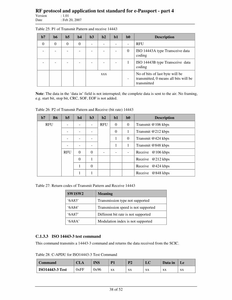
RF protocol and application test standard for e-Passport - part 4 Version : 1.01
Date : Feb 20, 2007
38 of 52
Table 25: P1 of Transmit Pattern and receive 14443
b7 b6 b5 b4 b3 b2 b1 b0 Description
0 0 0 0 - - - - RFU
- - - - - - - 0 ISO 14443A type Transceive data
coding
- - - - - - - 1 ISO 14443B type Transceive data
coding
xxx
-
No of bits of last byte will be
transmitted, 0 means all bits will be
transmitted
Note: The data in the ‘data in’ field is not interrupted; the complete data is sent to the air. No framing,
e.g. start bit, stop bit, CRC, SOF, EOF is not added.
Table 26: P2 of Transmit Pattern and Receive (bit rate) 14443
b7 B6 b5 b4 b3 b2 b1 b0 Description
- - - 0 0 Transmit @106 kbps
- - - 0 1 Transmit @212 kbps
- - - 1 0 Transmit @424 kbps
- - -
RFU
1 1 Transmit @848 kbps
0 0 - - - Receive @106 kbps
0 1 Receive @212 kbps
1 0 Receive @424 kbps
RFU
RFU
1 1 Receive @848 kbps
Table 27: Return codes of Transmit Pattern and Receive 14443
SW1SW2 Meaning
‘6A83’ Transmission type not supported
‘6A84’ Transmission speed is not supported
‘6A87’ Different bit rate is not supported
‘6A8A’ Modulation index is not supported
C.1.3.3 ISO 14443-3 test command
This command transmits a 14443-3 command and returns the data received from the SCIC.
Table 28: C-APDU for ISO14443-3 Test Command
Command CLA INS P1 P2 LC Data in Le
ISO14443-3 Test 0xFF 0x96 xx xx xx xx xx
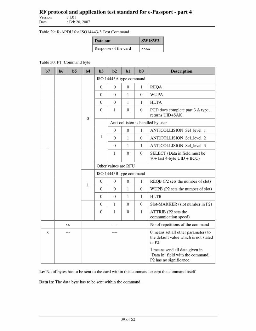
RF protocol and application test standard for e-Passport - part 4 Version : 1.01
Date : Feb 20, 2007
39 of 52
Table 29: R-APDU for ISO14443-3 Test Command
Data out SW1SW2
Response of the card xxxx
Table 30: P1: Command byte
b7 b6 b5 b4 b3 b2 b1 b0 Description
ISO 14443A type command
0 0 0 1 REQA
0 0 1 0 WUPA
0 0 1 1 HLTA
0 1 0 0 PCD does complete part 3 A type,
returns UID+SAK
Anti-collision is handled by user
0 0 1 ANTICOLLISION Sel_level 1
0 1 0 ANTICOLLISION Sel_level 2
0 1 1 ANTICOLLISION Sel_level 3
1
1 0 0 SELECT (Data in field must be
70+ last 4-byte UID + BCC)
0
Other values are RFU
ISO 14443B type command
0 0 0 1 REQB (P2 sets the number of slot)
0 0 1 0 WUPB (P2 sets the number of slot) 1
0 0 1 1 HLTB
0 1 0 0 Slot-MARKER (slot number in P2)
--
0 1 0 1 ATTRIB (P2 sets the
communication speed)
xx ---- No of repetitions of the command
x --- ---- 0 means set all other parameters to
the default value which is not stated
in P2.
1 means send all data given in
‘Data in’ field with the command,
P2 has no significance.
Lc: No of bytes has to be sent to the card within this command except the command itself.
Data in: The data byte has to be sent within the command.
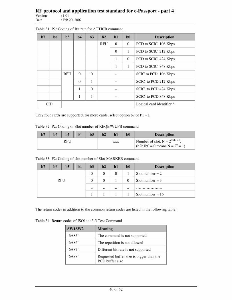
RF protocol and application test standard for e-Passport - part 4 Version : 1.01
Date : Feb 20, 2007
40 of 52
Table 31: P2: Coding of Bit rate for ATTRIB command
b7 b6 b5 b4 b3 b2 b1 b0 Description
0 0 PCD to SCIC 106 Kbps
0 1 PCD to SCIC 212 Kbps
1 0 PCD to SCIC 424 Kbps
RFU
1 1 PCD to SCIC 848 Kbps
0 0 -- SCIC to PCD 106 Kbps
0 1 -- SCIC to PCD 212 Kbps
1 0 -- SCIC to PCD 424 Kbps
RFU
1 1 -- SCIC to PCD 848 Kbps
CID Logical card identifier *
Only four cards are supported, for more cards, select option b7 of P1 =1.
Table 32: P2: Coding of Slot number of REQB/WUPB command
b7 b6 b5 b4 b3 b2 b1 b0 Description
RFU xxx Number of slot. N = 2(b2b1b0)
;
(b2b1b0 = 0 means N = 20 = 1)
Table 33: P2: Coding of slot number of Slot-MARKER command
b7 b6 b5 b4 b3 b2 b1 b0 Description
0 0 0 1 Slot number = 2
0 0 1 0 Slot number = 3
.. .. .. .. ………………..
RFU
1 1 1 1 Slot number = 16
The return codes in addition to the common return codes are listed in the following table:
Table 34: Return codes of ISO14443-3 Test Command
SW1SW2 Meaning
‘6A85’ The command is not supported
‘6A86’ The repetition is not allowed
‘6A87’ Different bit rate is not supported
‘6A88’ Requested buffer size is bigger than the
PCD buffer size
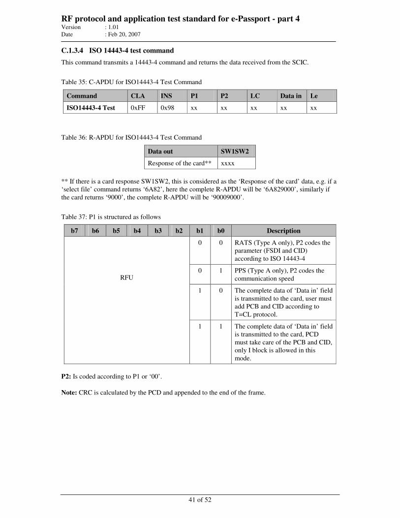
RF protocol and application test standard for e-Passport - part 4 Version : 1.01
Date : Feb 20, 2007
41 of 52
C.1.3.4 ISO 14443-4 test command
This command transmits a 14443-4 command and returns the data received from the SCIC.
Table 35: C-APDU for ISO14443-4 Test Command
Command CLA INS P1 P2 LC Data in Le
ISO14443-4 Test 0xFF 0x98 xx xx xx xx xx
Table 36: R-APDU for ISO14443-4 Test Command
Data out SW1SW2
Response of the card** xxxx
** If there is a card response SW1SW2, this is considered as the ‘Response of the card’ data, e.g. if a
‘select file’ command returns ‘6A82’, here the complete R-APDU will be ‘6A829000’, similarly if
the card returns ‘9000’, the complete R-APDU will be ‘90009000’.
Table 37: P1 is structured as follows
b7 b6 b5 b4 b3 b2 b1 b0 Description
0 0 RATS (Type A only), P2 codes the
parameter (FSDI and CID)
according to ISO 14443-4
0 1 PPS (Type A only), P2 codes the
communication speed
1 0 The complete data of ‘Data in’ field
is transmitted to the card, user must
add PCB and CID according to
T=CL protocol.
RFU
1 1 The complete data of ‘Data in’ field
is transmitted to the card, PCD
must take care of the PCB and CID,
only I block is allowed in this
mode.
P2: Is coded according to P1 or ‘00’.
Note: CRC is calculated by the PCD and appended to the end of the frame.
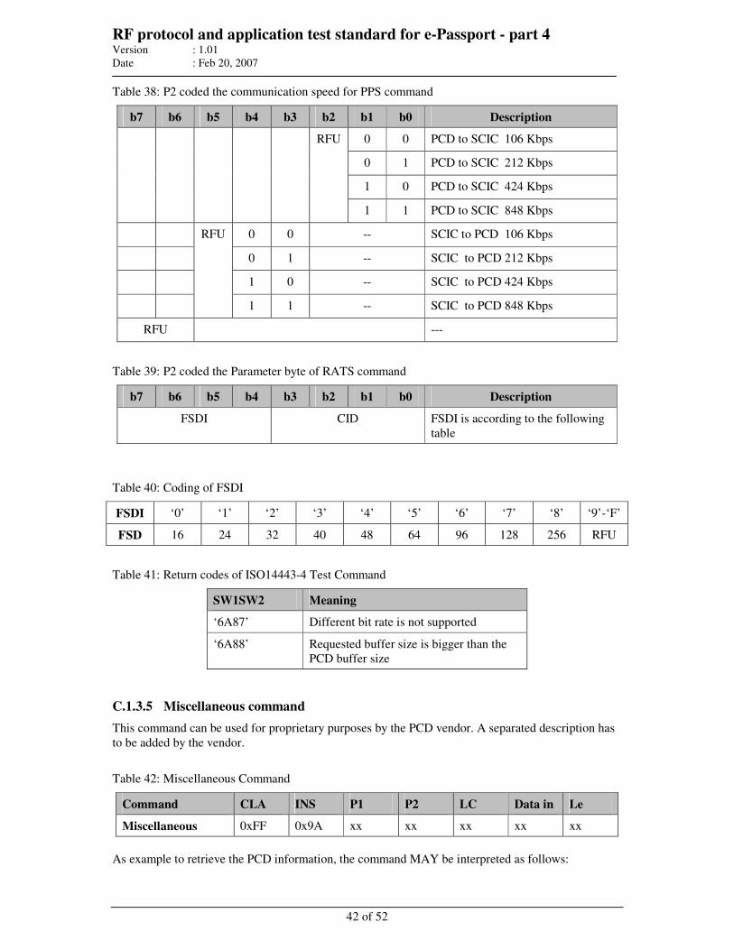
RF protocol and application test standard for e-Passport - part 4 Version : 1.01
Date : Feb 20, 2007
42 of 52
Table 38: P2 coded the communication speed for PPS command
b7 b6 b5 b4 b3 b2 b1 b0 Description
0 0 PCD to SCIC 106 Kbps
0 1 PCD to SCIC 212 Kbps
1 0 PCD to SCIC 424 Kbps
RFU
1 1 PCD to SCIC 848 Kbps
0 0 -- SCIC to PCD 106 Kbps
0 1 -- SCIC to PCD 212 Kbps
1 0 -- SCIC to PCD 424 Kbps
RFU
1 1 -- SCIC to PCD 848 Kbps
RFU ---
Table 39: P2 coded the Parameter byte of RATS command
b7 b6 b5 b4 b3 b2 b1 b0 Description
FSDI CID FSDI is according to the following
table
Table 40: Coding of FSDI
FSDI ‘0’ ‘1’ ‘2’ ‘3’ ‘4’ ‘5’ ‘6’ ‘7’ ‘8’ ‘9’-‘F’
FSD 16 24 32 40 48 64 96 128 256 RFU
Table 41: Return codes of ISO14443-4 Test Command
SW1SW2 Meaning
‘6A87’ Different bit rate is not supported
‘6A88’ Requested buffer size is bigger than the
PCD buffer size
C.1.3.5 Miscellaneous command
This command can be used for proprietary purposes by the PCD vendor. A separated description has
to be added by the vendor.
Table 42: Miscellaneous Command
Command CLA INS P1 P2 LC Data in Le
Miscellaneous 0xFF 0x9A xx xx xx xx xx
As example to retrieve the PCD information, the command MAY be interpreted as follows:
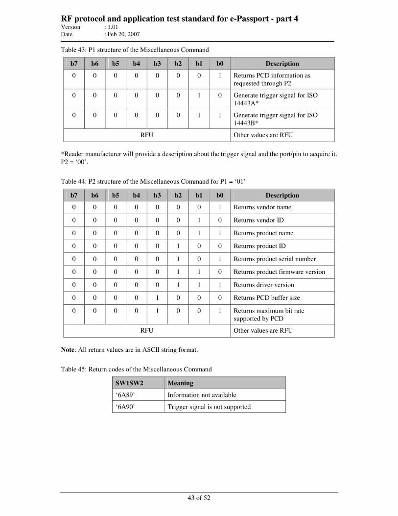
RF protocol and application test standard for e-Passport - part 4 Version : 1.01
Date : Feb 20, 2007
43 of 52
Table 43: P1 structure of the Miscellaneous Command
b7 b6 b5 b4 b3 b2 b1 b0 Description
0 0 0 0 0 0 0 1 Returns PCD information as
requested through P2
0 0 0 0 0 0 1 0 Generate trigger signal for ISO
14443A*
0 0 0 0 0 0 1 1 Generate trigger signal for ISO
14443B*
RFU Other values are RFU
*Reader manufacturer will provide a description about the trigger signal and the port/pin to acquire it.
P2 = ‘00’.
Table 44: P2 structure of the Miscellaneous Command for P1 = ‘01’
b7 b6 b5 b4 b3 b2 b1 b0 Description
0 0 0 0 0 0 0 1 Returns vendor name
0 0 0 0 0 0 1 0 Returns vendor ID
0 0 0 0 0 0 1 1 Returns product name
0 0 0 0 0 1 0 0 Returns product ID
0 0 0 0 0 1 0 1 Returns product serial number
0 0 0 0 0 1 1 0 Returns product firmware version
0 0 0 0 0 1 1 1 Returns driver version
0 0 0 0 1 0 0 0 Returns PCD buffer size
0 0 0 0 1 0 0 1 Returns maximum bit rate
supported by PCD
RFU Other values are RFU
Note: All return values are in ASCII string format.
Table 45: Return codes of the Miscellaneous Command
SW1SW2 Meaning
‘6A89’ Information not available
‘6A90’ Trigger signal is not supported
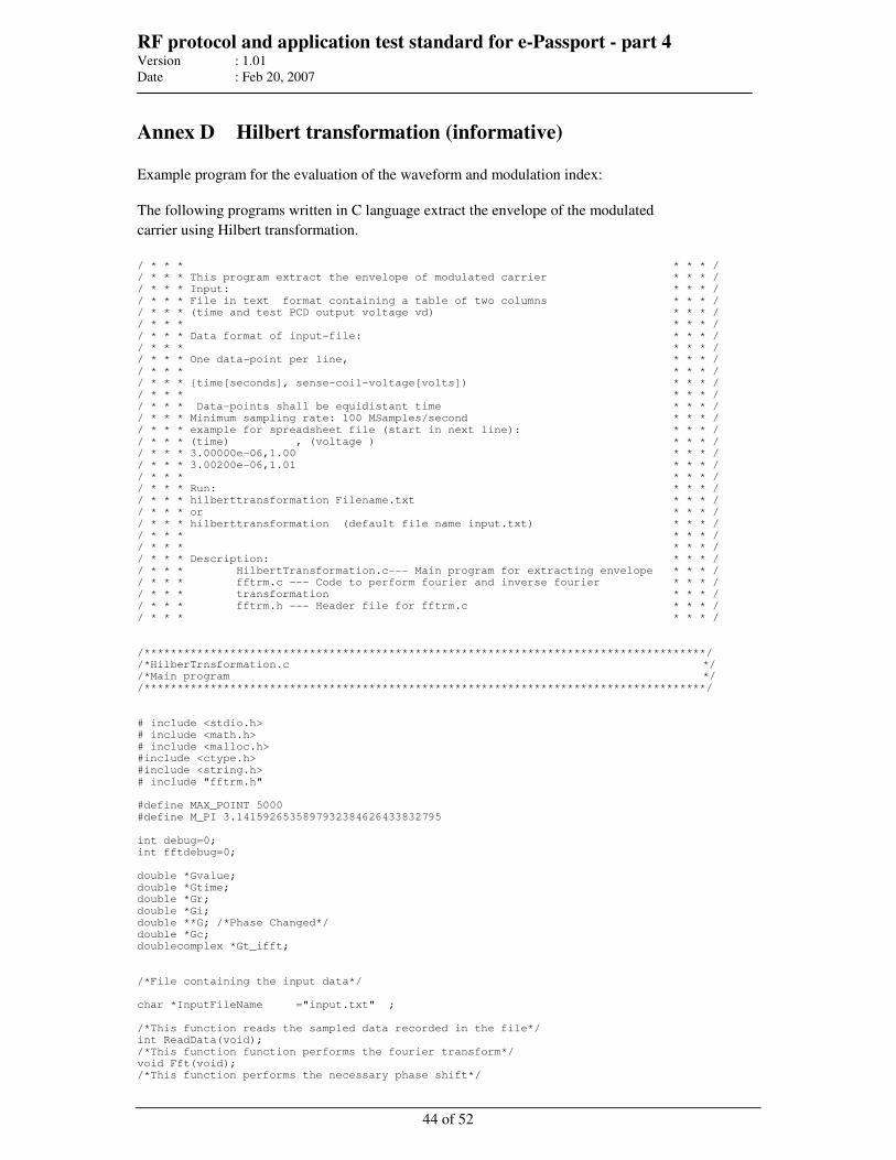
RF protocol and application test standard for e-Passport - part 4 Version : 1.01
Date : Feb 20, 2007
44 of 52
Annex D Hilbert transformation (informative)
Example program for the evaluation of the waveform and modulation index:
The following programs written in C language extract the envelope of the modulated
carrier using Hilbert transformation.
/ * * * * * * /
/ * * * This program extract the envelope of modulated carrier * * * /
/ * * * Input: * * * /
/ * * * File in text format containing a table of two columns * * * /
/ * * * (time and test PCD output voltage vd) * * * /
/ * * * * * * /
/ * * * Data format of input-file: * * * /
/ * * * * * * /
/ * * * One data-point per line, * * * /
/ * * * * * * /
/ * * * time[seconds], sense-coil-voltage[volts]) * * * /
/ * * * * * * /
/ * * * Data-points shall be equidistant time * * * /
/ * * * Minimum sampling rate: 100 MSamples/second * * * /
/ * * * example for spreadsheet file (start in next line): * * * /
/ * * * (time) , (voltage ) * * * /
/ * * * 3.00000e-06,1.00 * * * /
/ * * * 3.00200e-06,1.01 * * * /
/ * * * * * * /
/ * * * Run: * * * /
/ * * * hilberttransformation Filename.txt * * * /
/ * * * or * * * /
/ * * * hilberttransformation (default file name input.txt) * * * /
/ * * * * * * /
/ * * * * * * /
/ * * * Description: * * * /
/ * * * HilbertTransformation.c--- Main program for extracting envelope * * * /
/ * * * fftrm.c --- Code to perform fourier and inverse fourier * * * /
/ * * * transformation * * * /
/ * * * fftrm.h --- Header file for fftrm.c * * * /
/ * * * * * * /
/*************************************************************************************/
/*HilberTrnsformation.c */
/*Main program */
/*************************************************************************************/
# include <stdio.h>
# include <math.h>
# include <malloc.h>
#include <ctype.h>
#include <string.h>
# include "fftrm.h"
#define MAX_POINT 5000
#define M_PI 3.1415926535897932384626433832795
int debug=0;
int fftdebug=0;
double *Gvalue;
double *Gtime;
double *Gr;
double *Gi;
double **G; /*Phase Changed*/
double *Gc;
doublecomplex *Gt_ifft;
/*File containing the input data*/
char *InputFileName ="input.txt" ;
/*This function reads the sampled data recorded in the file*/
int ReadData(void);
/*This function function performs the fourier transform*/
void Fft(void);
/*This function performs the necessary phase shift*/
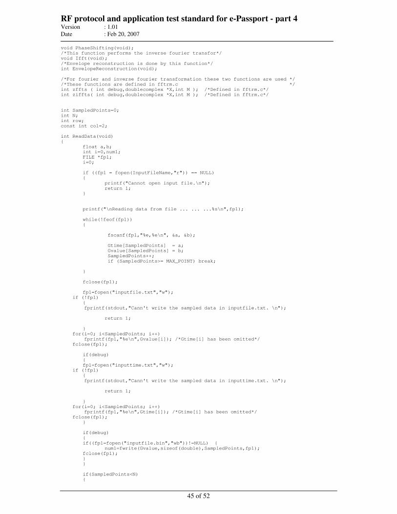
RF protocol and application test standard for e-Passport - part 4 Version : 1.01
Date : Feb 20, 2007
45 of 52
void PhaseShifting(void);
/*This function performs the inverse fourier transfor*/
void Ifft(void);
/*Envelope reconstruction is done by this function*/
int EnvelopeReconstruction(void);
/*For fourier and inverse fourier transformation these two functions are used */
/*These functions are defined in fftrm.c */
int zffts ( int debug,doublecomplex *X,int M ); /*Defined in fftrm.c*/
int ziffts( int debug,doublecomplex *X,int M ); /*Defined in fftrm.c*/
int SampledPoints=0;
int N;
int row;
const int col=2;
int ReadData(void)
float a,b;
int i=0,num1;
FILE *fp1;
i=0;
if ((fp1 = fopen(InputFileName,"r")) == NULL)
printf("Cannot open input file.\n");
return 1;
printf("\nReading data from file ... ... ...%s\n",fp1);
while(!feof(fp1))
fscanf(fp1,"%e,%e\n", &a, &b);
Gtime[SampledPoints] = a;
Gvalue[SampledPoints] = b;
SampledPoints++;
if (SampledPoints>= MAX_POINT) break;
fclose(fp1);
fp1=fopen("inputfile.txt","w");
if (!fp1)
fprintf(stdout,"Cann't write the sampled data in inputfile.txt. \n");
return 1;
for(i=0; i<SampledPoints; i++)
fprintf(fp1,"%e\n",Gvalue[i]); /*Gtime[i] has been omitted*/
fclose(fp1);
if(debug)
fp1=fopen("inputtime.txt","w");
if (!fp1)
fprintf(stdout,"Cann't write the sampled data in inputtime.txt. \n");
return 1;
for(i=0; i<SampledPoints; i++)
fprintf(fp1,"%e\n",Gtime[i]); /*Gtime[i] has been omitted*/
fclose(fp1);
if(debug)
if((fp1=fopen("inputfile.bin","wb"))!=NULL)
num1=fwrite(Gvalue,sizeof(double),SampledPoints,fp1);
fclose(fp1);
if(SampledPoints<N)
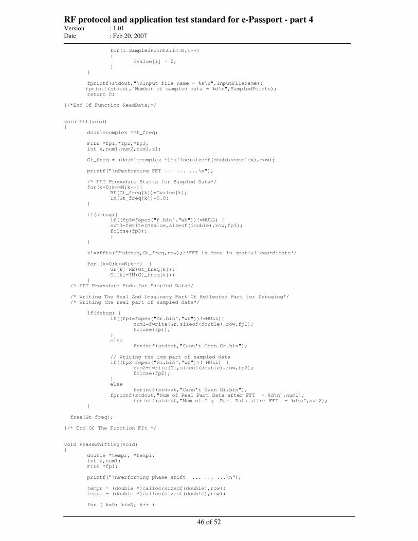
RF protocol and application test standard for e-Passport - part 4 Version : 1.01
Date : Feb 20, 2007
46 of 52
for(i=SampledPoints;i<=N;i++)
Gvalue[i] = 0;
fprintf(stdout,"\nInput file name = %s\n",InputFileName);
fprintf(stdout,"Number of sampled data = %d\n",SampledPoints);
return 0;
/*End Of Function ReadData;*/
void Fft(void)
doublecomplex *Gt_freq;
FILE *fp1,*fp2,*fp3;
int k,num1,num2,num3,z1;
Gt_freq = (doublecomplex *)calloc(sizeof(doublecomplex),row);
printf("\nPerforming FFT ... ... ...\n");
/* FFT Procedure Starts for Sampled Data*/
for(k=0;k<=N;k++)
RE(Gt_freq[k])=Gvalue[k];
IM(Gt_freq[k])=0.0;
if(debug)
if((fp3=fopen("f.bin","wb"))!=NULL)
num3=fwrite(Gvalue,sizeof(double),row,fp3);
fclose(fp3);
z1=zffts(fftdebug,Gt_freq,row);/*FFT is done in spatial coordicate*/
for (k=0;k<=N;k++)
Gr[k]=RE(Gt_freq[k]);
Gi[k]=IM(Gt_freq[k]);
/* FFT Procedure Ends for Sampled Data*/
/* Writing The Real And Imaginary Part Of Reflected Part for Debuging*/
/* Writing the real part of sampled data*/
if(debug)
if((fp1=fopen("Gr.bin","wb"))!=NULL)
num1=fwrite(Gr,sizeof(double),row,fp1);
fclose(fp1);
else
fprintf(stdout,"Cann't Open Gr.bin");
// Writing the img part of sampled data
if((fp2=fopen("Gi.bin","wb"))!=NULL)
num2=fwrite(Gi,sizeof(double),row,fp2);
fclose(fp2);
else
fprintf(stdout,"Cann't Open Gi.bin");
fprintf(stdout,"Num of Real Part Data after FFT = %d\n",num1);
fprintf(stdout,"Num of Img Part Data after FFT = %d\n",num2);
free(Gt_freq);
/* End Of The Function Fft */
void PhaseShifting(void)
double *tempr, *tempi;
int k,num1;
FILE *fp1;
printf("\nPerforming phase shift ... ... ...\n");
tempr = (double *)calloc(sizeof(double),row);
tempi = (double *)calloc(sizeof(double),row);
for ( k=0; k<=N; k++ )
RF protocol and application test standard for e-Passport - part 4 Version : 1.01
Date : Feb 20, 2007
47 of 52
tempr[k]=Gr[k];
tempi[k]=Gi[k];
for ( k=0; k<=ceil(N/2); k++ )
Gr[k] = tempi[k];
Gi[k] = -tempr[k];
for ( k=(int)ceil(N/2)+1; k<=N; k++ )
Gr[k] = -tempi[k];
Gi[k] = tempr[k];
if(debug)
if((fp1=fopen("ffrpt.bin","wb"))!=NULL)
num1=fwrite(Gr,sizeof(double),row,fp1);
fclose(fp1);
if((fp1=fopen("ffipt.bin","wb"))!=NULL)
num1=fwrite(Gi,sizeof(double),row,fp1);
fclose(fp1);
free (tempr);
free (tempi);
/*End of PhaseShift() function*/
void Ifft(void)
double *Gt_tmp; /* It takes the real part of R_ifft*/
double *Gt_tmpi;
FILE *fp1;
int k,i,z1,num1;
Gt_tmp = (double *)calloc(sizeof(double),row);
Gt_tmpi = (double *)calloc(sizeof(double),row);
printf("\nPerforming IFFT ... ... ...\n");
for (k=0;k<=N;k++)
Gt_ifft[k].r=Gr[k];
Gt_ifft[k].i=Gi[k];
z1=ziffts(fftdebug,Gt_ifft,row);/*IFFT of the signal in spatial coordinate*/
printf("\nEnd of IFFT ... ...\n");
for (k=0;k<=N;k++)
Gt_tmp[k]=Gt_ifft[k].r;
if(debug)
fp1=fopen("ifft.txt","w");
if (!fp1)
fprintf(stdout,"Cann't write in %s\n",fp1);
for(i=0; i<=N; i++)
fprintf(fp1,"%.4e\n",(Gt_ifft[i].r));
fclose(fp1);
printf("\nPerforming IFFT writing... ... ...\n");
if(debug)
if((fp1=fopen("iffrpt.bin","wb"))!=NULL)
num1=fwrite(Gt_tmp,sizeof(double),row,fp1);
fclose(fp1);
if((fp1=fopen("iffipt.bin","wb"))!=NULL)
num1=fwrite(Gt_tmpi,sizeof(double),row,fp1);
fclose(fp1);
free(Gt_tmp );
free(Gt_tmpi );
/* End Of Function Ifft*/
RF protocol and application test standard for e-Passport - part 4 Version : 1.01
Date : Feb 20, 2007
48 of 52
int EnvelopeReconstruction(void)
FILE *fp1;
int k;
doublecomplex *G; /*Input signal readed from input file in complex form*/
doublecomplex *Ganalytical;/*Analytical function of our input signal*/
double *test;
double *sqrtr;
double *sqrti;
G = (doublecomplex *)calloc(sizeof(doublecomplex),row);
Ganalytical = (doublecomplex *)calloc(sizeof(doublecomplex),row);
test = (double *)calloc(sizeof(double),row);
sqrtr=(double *)calloc(sizeof(double),row);
sqrti=(double *)calloc(sizeof(double),row);
printf("\nPerforming envelope extraction ... ... ...\n");
for (k=0;k<=N;k++)
RE(G[k]) = Gvalue[k];
IM(G[k]) = 0.0;
for (k=0;k<=N;k++)
RE(Ganalytical[k])=G[k].r;
IM(Ganalytical[k])=Gt_ifft[k].r;
for (k=0;k<=N;k++)
sqrtr[k]=sqrt(Ganalytical[k].r*Ganalytical[k].r+Ganalytical[k].i*Ganalytical[k].i);
fp1=fopen("output.txt","w");
if (!fp1)
fprintf(stdout,"Cann't write extracted envelope in output.txt.\n");
free(G);
free(Ganalytical);
free(test);
free(sqrtr);
free(sqrti);
return 1;
for(k=0; k<SampledPoints; k++)
fprintf(fp1,"%e,%e\n",Gtime[k],sqrtr[k]);
printf("\nExtracted envelope is written in %s\n","output.txt");
fclose(fp1);
free(G);
free(Ganalytical);
free(test);
free(sqrtr);
free(sqrti);
return 0;
/*Main Function*/
int main(int argc, char *argv[])
int status=0,i=1;
char fname[256],c;
if(argc==2)
printf("\nInput File Name: ");
//scanf("%s,InputFileName");
strcpy(fname, argv[1]);
InputFileName= fname;
printf("%s\n",InputFileName);
else
printf("\nUse default file : %s\n", InputFileName);
//Reading the sampled data
RF protocol and application test standard for e-Passport - part 4 Version : 1.01
Date : Feb 20, 2007
49 of 52
do
N=(int)pow(2,i)-1;
i++;
while (MAX_POINT > N);
if (debug)
printf("N= %d\n",N);
row=N+1;
Gvalue = (double *)calloc(sizeof(double),row);
Gtime = (double *)calloc(sizeof(double),row);
Gr = (double *)calloc(sizeof(double),row);
Gi = (double *)calloc(sizeof(double),row);
Gt_ifft= (doublecomplex *)calloc(sizeof(doublecomplex),row);
Gc = (double *)calloc(sizeof(double),row);
status = ReadData();
if (status== 1) goto MainExit;
/*Does FFT*/
Fft();
/*Appropriate Phahe has been Shifted*/
PhaseShifting();
/*Does IFFT*/
Ifft();
/*Envelope Reconstruction */
status = EnvelopeReconstruction();
if (status== 1) goto MainExit;
printf("\n\n==================================\n\n");
printf("Input file name : %s \n",InputFileName);
//printf("Gvalue[] has the input value\n");
//printf("sqrtr[] has the output value\n");
printf("Output file name output.txt\n");
printf("\n==================================\n\n");
MainExit:
free(Gvalue);
free(Gtime);
free(Gr);
free(Gi);
free(Gt_ifft);
free(Gc);
printf("\n\nPress any key to exit.\n");
scanf("%c",&c);
return (0);
/*End Of Main*/
/******************************************************************************************/
/*fftrm.h */
/*This is the header file for fftrm.c */
/******************************************************************************************/
#ifndef FFTRM_H
#define FFTRM_H
#define RE(z) ((z).r)
#define IM(z) ((z).i)
typedef float real;
typedef double doublereal;
typedef struct real r, i; complex;
typedef struct doublereal r, i; doublecomplex;
int zffts (int debug, doublecomplex *X, int M);
int ziffts (int debug, doublecomplex *X, int M);
void zfftrmc(doublecomplex *X, int M, int P, float D);
void rmpo (int *rv, int *rvp );
#endif
/******************************************************************************************/
/*fftrm.c */
/*This code contains the necessary function for fourier and inverse fourier transformation*/
/******************************************************************************************/
RF protocol and application test standard for e-Passport - part 4 Version : 1.01
Date : Feb 20, 2007
50 of 52
#include <stdio.h>
#include <math.h>
#include <malloc.h>
#include "fftrm.h"
//#ifndef M_PI
#define M_PI 3.1415926535897932384626433832795
//#endif
float *WR;
float *WI;
doublereal *DWR;
doublereal *DWI;
void rmpo( int *rv, int *rvp )
int value_h;
int n;
n = 1;
*rvp = -1;
value_h = 1;
while ( value_h > 0 )
value_h = *rv - n;
(*rvp)++;
n += n;
void zfftrmc( doublecomplex *X, int M, int P, float D )
int MV2,MM1,J,I,K,L,LE,LE1,IP,IQ,IND,IND1,R;
int I1,J1,IPOTR;
float A,B;
float WCOS,WSIN;
float VR,VI;
float ARG;
static int IPOTC;
static float DALT;
IPOTR = 0;
DWR = (doublereal *)calloc(M,sizeof(doublereal));
DWI = (doublereal *)calloc(M,sizeof(doublereal));
/* if (IPOTC == P & D == DALT) goto warmstart; */
IPOTC = P;
DALT = (float)D;
LE = 1;
IND = 0;
for (L=1;L<=P;L++)
LE1 = LE;
LE = LE*2;
DWR[IND] = 1.0;
DWI[IND] = 0.0;
ARG = (float)M_PI/(float)LE1;
WCOS = (float)cos(ARG);
WSIN = (float)(D*sin(ARG));
for (R=1;R<=LE1;R++)
IND1 = IND+1;
A = (float)DWR[IND];
B = (float)DWI[IND];
DWR[IND1] = A*WCOS - B*WSIN;
DWI[IND1] = B*WCOS + A*WSIN;
++IND;
/* warmstart: */
MV2=M/2;
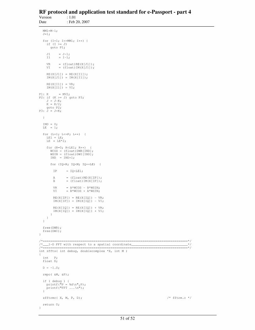
RF protocol and application test standard for e-Passport - part 4 Version : 1.01
Date : Feb 20, 2007
51 of 52
MM1=M-1;
J=1;
for (I=1; I<=MM1; I++)
if (I >= J)
goto P1;
J1 = J-1;
I1 = I-1;
VR = (float)RE(X[J1]);
VI = (float)IM(X[J1]);
RE(X[J1]) = RE(X[I1]);
IM(X[J1]) = IM(X[I1]);
RE(X[I1]) = VR;
IM(X[I1]) = VI;
P1: K = MV2;
P2: if (K >= J) goto P3;
J = J-K;
K = K/2;
goto P2;
P3: J = J+K;
IND = 0;
LE = 1;
for (L=1; L<=P; L++)
LE1 = LE;
LE = LE*2;
for (R=0; R<LE1; R++)
WCOS = (float)DWR[IND];
WSIN = (float)DWI[IND];
IND = IND+1;
for (IQ=R; IQ<M; IQ+=LE)
IP = IQ+LE1;
A = (float)RE(X[IP]);
B = (float)IM(X[IP]);
VR = A*WCOS - B*WSIN;
VI = B*WCOS + A*WSIN;
RE(X[IP]) = RE(X[IQ]) - VR;
IM(X[IP]) = IM(X[IQ]) - VI;
RE(X[IQ]) = RE(X[IQ]) + VR;
IM(X[IQ]) = IM(X[IQ]) + VI;
free(DWR);
free(DWI);
/*=============================================================================*/
/*___1-D FFT with respect to a spatial coordinate______________________________*/
/*=============================================================================*/
int zffts( int debug, doublecomplex *X, int M )
int P;
float D;
D = -1.0;
rmpo( &M, &P);
if ( debug )
printf("P = %d\n",P);
printf("FFT ...\n");
zfftrmc( X, M, P, D); /* fftrm.c */
return 0;
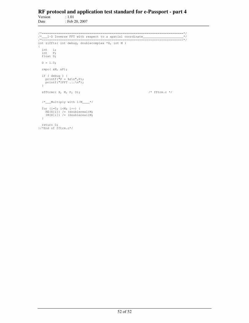
RF protocol and application test standard for e-Passport - part 4 Version : 1.01
Date : Feb 20, 2007
52 of 52
/*=============================================================================*/
/*___1-D Inverse FFT with respect to a spatial coordinate______________________*/
/*=============================================================================*/
int ziffts( int debug, doublecomplex *X, int M )
int i;
int P;
float D;
D = 1.0;
rmpo( &M, &P);
if ( debug )
printf("P = %d\n",P);
printf("IFFT ...\n");
zfftrmc( X, M, P, D); /* fftrm.c */
/*___Multiply with 1/M____*/
for (i=0; i<M; i++)
RE(X[i]) /= (doublereal)M;
IM(X[i]) /= (doublereal)M;
return 0;
/*End of fftrm.c*/


![Machine Readable Travel Document with [ICAO Application]](https://static.fdocuments.us/doc/165x107/613c1a9822e01a42d40e9dfc/machine-readable-travel-document-with-icao-application.jpg)