Tecal Accu-Temp Instruction Manual - Techne … · Tecal Accu-Temp INSTRUCTION MANUAL Table of...
34
1 05/31/019 TECHNE INC. INSTRUCTION MANUAL MODEL TECAL ACCU-TEMP TEMPERATURE MONITOR ITS-90 S/N____________
Transcript of Tecal Accu-Temp Instruction Manual - Techne … · Tecal Accu-Temp INSTRUCTION MANUAL Table of...

1 05/31/019
TECHNE INC.
INSTRUCTION MANUAL
MODEL TECAL ACCU-TEMP
TEMPERATURE MONITOR
ITS-90
S/N____________

2 05/31/01
Tecal Accu-Temp
INSTRUCTION MANUAL
Table of contents
Page
1. GENERAL INFORMATION 1
1.1 FEATURES 1
1.2 INSTRUMENT IDENTIFICATION & OPTIONS 2
1.3 TECHNICAL SPECIFICATIONS 3
1.4 WARRANTY 6
1.5 UNPACKING AND SHIPPING 6
1.6 PRELIMINARY CHECK OUT 6
2. STANDARD OPERATION 11
2.1 SENSOR CONNECTION 11
2.2 POWER CONNECTION 11
2.3 MATCHING THE INSTRUMENT TO A SPECIFIC SENSOR 12
2.3.1 Identifying ITS-90 Sub Ranges and Coefficients 12
2.3.2 Formatting the ITS-90 Coefficients 12
2.3.3 Programming the Coefficients into Memory 13
2.3.4 Programming Examples 15
2.4 CHECKING CURRENT SENSOR COEFFICIENTS 17
2.5 SELECTING THE SCALE; °F,ohms,°C 18
2.6 CHECKSUM VERIFICATION OF PROGRAMMED VARIABLES 19
3 05/31/019
3.0 CALIBRATION PROCEDURES 21
3.1 Calibration of Ohmmeter Section 21
3.2 Verifying resistance to temperature calculations 24
3.3 Spot check of system accuracy 25
4.0 Theory of operation 27
5.0 Troubleshooting 30
4 05/31/01
1. GENERAL INFORMATION
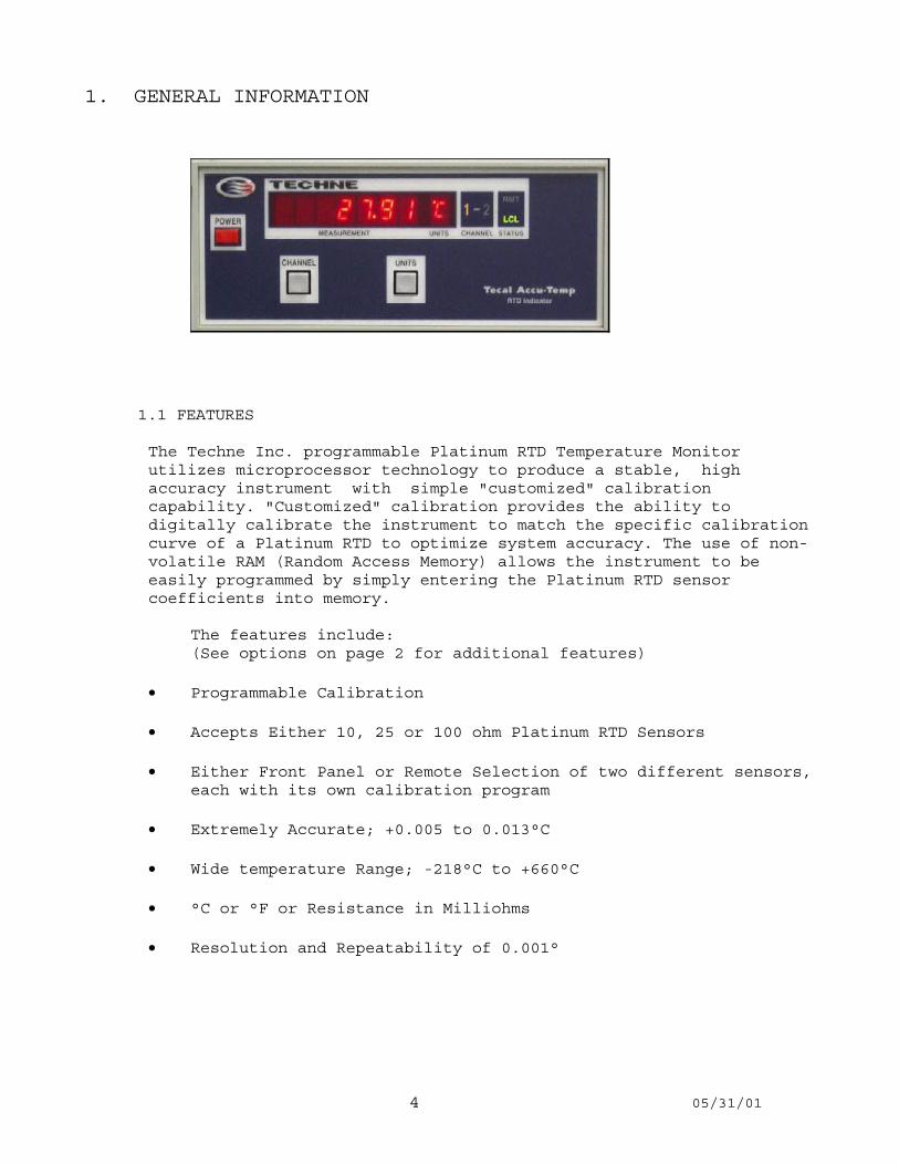
1.1 FEATURES
The Techne Inc. programmable Platinum RTD Temperature Monitorutilizes microprocessor technology to produce a stable, highaccuracy instrument with simple "customized" calibrationcapability. "Customized" calibration provides the ability todigitally calibrate the instrument to match the specific calibrationcurve of a Platinum RTD to optimize system accuracy. The use of non-volatile RAM (Random Access Memory) allows the instrument to beeasily programmed by simply entering the Platinum RTD sensorcoefficients into memory.
The features include:(See options on page 2 for additional features)
• Programmable Calibration
• Accepts Either 10, 25 or 100 ohm Platinum RTD Sensors
• Either Front Panel or Remote Selection of two different sensors,each with its own calibration program
• Extremely Accurate; +0.005 to 0.013°C
• Wide temperature Range; -218°C to +660°C
• °C or °F or Resistance in Milliohms
• Resolution and Repeatability of 0.001°
5 05/31/019
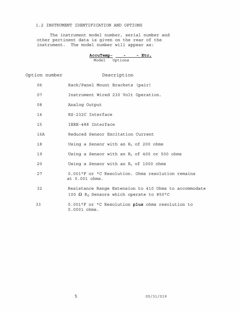
1.2 INSTRUMENT IDENTIFICATION AND OPTIONS
The instrument model number, serial number andother pertinent data is given on the rear of theinstrument. The model number will appear as:
AccuTemp- - - Etc, Model Options
Option number Description
06 Rack/Panel Mount Brackets (pair)
07 Instrument Wired 230 Volt Operation.
08 Analog Output
14 RS-232C Interface
15 IEEE-488 Interface
16A Reduced Sensor Excitation Current
18 Using a Sensor with an R0 of 200 ohms
19 Using a Sensor with an R0 of 400 or 500 ohms
20 Using a Sensor with an R0 of 1000 ohms
27 0.001°F or °C Resolution. Ohms resolution remains at 0.001 ohms.
32 Resistance Range Extension to 410 Ohms to accommodate
100 Ω R0 Sensors which operate to 850°C
33 0.001°F or °C Resolution plus ohms resolution to 0.0001 ohms.

6 05/31/01
1.3 TECHNICAL SPECIFICATIONS (See options on page 2)
Instrument Range -218.00°C to 660.00°C or (See Note Page 4) -360.00°F to +1220.00°F or 0.000 to 340.000 ohms
Instrument Uncertainty ±0.10°C for(Single Measurement Mode) 10 Ohm Sensors@ 25°C+3°CCalibration in Accordance ±0.007°C forwith ITS-90 25 ohm sensors(Also see option 27 and option 33 on page 61) ±0.013°Cfor
100 ohm sensors
±0.002 ohms or 15 ppm.
Calibration Check 1 YearInterval
Resolution and Repeatability 0.001° on both °C and °F scales, 0.001 on ohms
Excitation Current 1 milliamp DC (nominal)
Sensor Type Platinum RTD R0 = 10 ohms, 25 ohms or 100 ohms. Any Alpha from (nominally) 0.00385 to 0.003925
Sensor Coefficients Rtp plus the required sensor coefficients, the number of which are dependent on the sub- range.
7 05/31/019
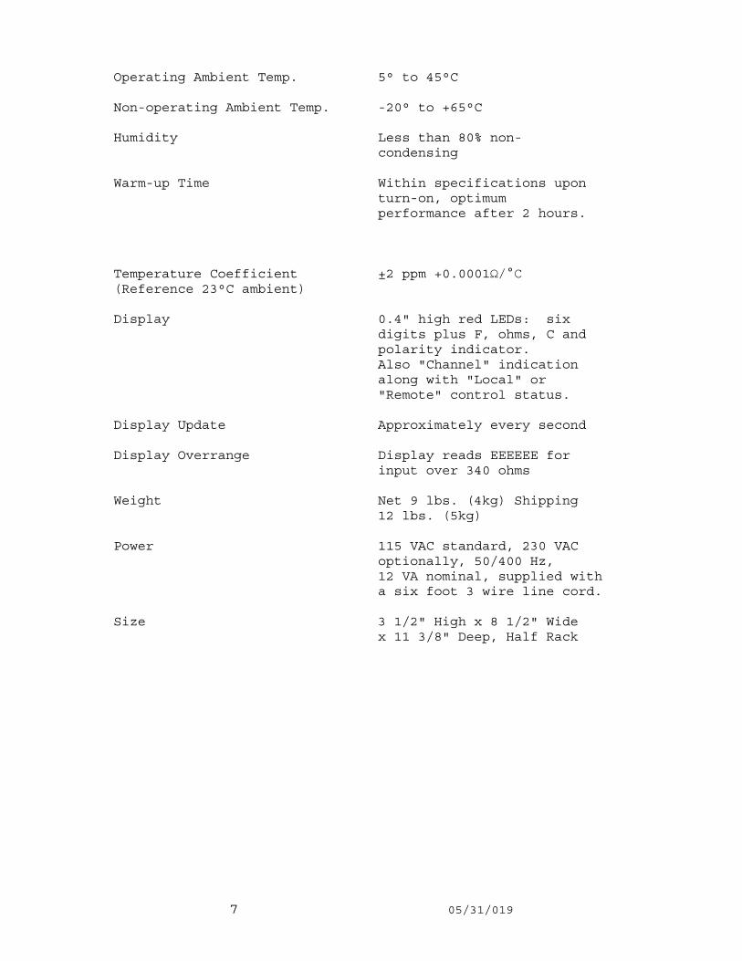
Operating Ambient Temp. 5° to 45°C
Non-operating Ambient Temp. -20° to +65°C
Humidity Less than 80% non- condensing
Warm-up Time Within specifications upon turn-on, optimum performance after 2 hours.
Temperature Coefficient ±2 ppm +0.0001Ω/°C(Reference 23°C ambient)
Display 0.4" high red LEDs: six digits plus F, ohms, C and polarity indicator. Also "Channel" indication along with "Local" or "Remote" control status.
Display Update Approximately every second
Display Overrange Display reads EEEEEE for input over 340 ohms
Weight Net 9 lbs. (4kg) Shipping 12 lbs. (5kg)
Power 115 VAC standard, 230 VAC optionally, 50/400 Hz, 12 VA nominal, supplied with a six foot 3 wire line cord.
Size 3 1/2" High x 8 1/2" Wide x 11 3/8" Deep, Half Rack

8 05/31/01
INTENTIONALLY
BLANK

9 05/31/019
1.4 WARRANTY
Techne warrants its products to be free from defects in materialand workmanship for one year after date of shipment, provided the unitshave been used within published ratings. The warranty is limited to ourrepairing or replacing without charge, F. O. B. our factory anydefective product if returned to our plant, transportation prepaid. Noother representation or warranty, either expressed or implied, is made,and in no event shall Instrulab be liable for consequential or otherdamages.
1.5 UNPACKING AND SHIPPING
After having unpacked the instrument, carefully examine it and anyenclosed accessories for physical damage and compliance with thepacking list. If any of the articles are missing or damaged,inspect the packing case for signs of damage or theft during shipmentand immediately report it to the carrier.
If it should become necessary to return the instrument to InstrulabInc., use the original packing material, if possible.
When returning instruments to the factory, give a full description ofthe failure and the mode of operation that was used when theinstrument failure occurred. Please include the name and phonenumber of someone we can contact, should we have any questions. Shipvia UPS or parcel post prepaid to:
Techne Inc.University Park Plaza743 Alexander Road
Princeton, N.J. 08540
1.6 PRELIMINARY CHECK-OUT
Please use the following procedure before applying power for thefirst time:
1. Remove the two top screws at the rear of the case.
2. Slide the top cover to the rear to inspect the instrument.
3. Verify that the vertical board(s), Display Board and option Board(s) and their cables are properly seated in their connectors.

10 05/31/01
DIMENSION DRAWINGS
Case Outline Drawing
Figure 1a

11 05/31/019
Case Outline Drawing
Figure 1b

12 05/31/01
Case Outline DrawingFigure 1c

13 05/31/019
TOP VIEW
Top View of Instrument Showing Programming SwitchesFigure 2

14 05/31/01
2.0 STANDARD OPERATION
2.1 SENSOR CONNECTIONS
Sensors are connected to a terminal strip that is located directlyunder the top cover of the instrument To connect the sensor leads, remove the top cover, insert the leadsthrough the hole in the back panel and connect to the four terminalsas shown on the terminal strip diagram. Note the input number on theterminal strip when making your connections, since each input willbe individually calibrated to a specific sensor.
The terminals are marked -c, -p, +P, and +C. If your sensor leadsare marked with the letters -c, -p, +P, and +C simply connect to theindicated terminals as. If your sensor has four unmarkedleads, connect the two leads with a common connection to the -c &-p terminals and the other two leads to the +P & +C terminals. Theorder is not important, just as long as the leads with the commonconnections are connected to the terminals with a common polarity.Interchanging of leads -p & -c or the leads +P & +C will not affectthe instrument's accuracy. Failure to use a four-lead system willresult in a reading error.
NOTE: If sensor(s) were purchased from Techne Inc. at the time ofpurchase of the instrument, the unit will be preprogrammed withsensor coefficients.
2.2 POWER CONNECTION
The standard model is designed to operate 115 VAC +10%. Modelsdesigned for 230 VAC operation contain the option number 07. Werecommend that a 3 wire U-ground receptacle be used. The instrumentis within rated specification at turn on. Optimum performance isobtained after 2 hours.
When the instrument is first turned on, the display will read "ItS-90", then it will light all segments, along with all decimal points.Then, if Option 14 is installed, it will read "rS-232" or, if Option15 is installed, it will read "IEEE 07". The two numbers are theinstrument address. Instrument will then commence to read sensorinput.

15 05/31/019
2.3 MATCHING THE INSTRUMENT TO A SPECIFIC SENSOR
2.3.1 IDENTIFYING ITS-90 SUB RANGES AND COEFFICIENTS
1. Instrument can be programmed for any range or sub rangethat falls within the limits of:
-218.7916°C (TP of Oxygen) to +660.323 °C (FP of Aluminum) (See note page 4)
2. The actual range depends on the calibration of your sensorand may be negative temperatures, positive temperatures or acombination of both.
3. The following table lists the "a, b, and c "coefficients for various sub ranges that may beprogrammed into the instrument.
LOWEST HIGHEST CALIBRATION CALIBRATION ASSIGNED TEMP. TEMP. COEFFICIENT IDENTIFICATION °C °C °C 0 1 2 3 4 5 6
0.00 to 962 Rtp a7 b7 c7 (See note page4) 0.00 to 660 Rtp a7 b7 c7 - - - 0.00 to 419 Rtp a8 b8 0 - - - 0.00 to 231 Rtp a9 b9 0 - - - 0.00 to 156 Rtp a10 0 0 - - - -38 to +0.01 to 29 Rtp a5 b5 0 - - - -189 to +0.01 Rtp - - - a4 b4 0 -218 to +0.01 Rtp - - - a3 b3 C1
Rtp = Resistance of sensor at the triple point of water, i.e. +0.01°C.
2.3.2 FORMATTING THE ITS-90 COEFFICIENTS
1. The coefficients received with your sensor(s) shouldappear similar to the following example.
Sub range = -189 to +500°C (419°C)
Rtp = 25.4768 ohms a4 = -1.6448498E-04 b4 = -5.2486782E-04 a8 = -9.2035954E-06 b8 = -1.1031022E-04
2. Entry of Rtp is directly as listed. Be sure to observedecimal point.

16 05/31/01
3. The required format for coefficient entry is as follows:
COEFFICIENT POLARITY COEFFICIENT ID# P=Positive 0=Rtp -=Negative 1,2&3=Pos. Temp. Coef.
4,5&6=Neg. Temp. Coef.
EXPONENT FIRST 5 DIGITS Single Digit Entry FROM COEFFICIENT
NOTE that correct formatting of the Coefficients requires therelocation of only the exponent to the beginning of the string.
2.3.3 PROGRAMMING THE COEFFICIENTS INTO MEMORY
Since the two inputs (input 1 & 2) are digitally independent of eachother, the programming procedure must be performed for both inputs.Select the desired input using the front panel input selectionswitch and proceed with the programming, then depress the inputswitch to change the input selection and proceed to program thesecond sensor.
First remove the two top cover retaining screws and slide off thetop cover, then turn on the power. A warm-up period is notnecessary since only the digital coefficients are being programmed.Now locate the function switch and the black, red, and graypushbutton switches, near the front of the instrument. (See figure 2for component locations.)
At this time, [prior to programming) the FUNCTION switch, positions#1 and 2 should be in the "off" position. See figure 3.
Close up of S2 Showing Sensor CoefficentProgramming Switches Figure
Figure 3

17 05/31/019
1. Move the FUNCTION switch, position 2 to the "on" position. Asmall number "0" should appear in the far right hand side ofthe digital display. This indicates that Rtp, is ready to beprogrammed. You will also note that the far left handdigit is flashing This indicates that this digit will accept achange in numerical value. Use the RED COUNT button to changethis digit to the number desired.
2. After the first digit is programmed, advance to the seconddigit by pressing the BLACK DIGIT SELECT button. Thesecond digit should now flash. Now program the number forthis digit just like the first digit, using the RED COUNT button.
3. Now program the rest of the digits using the BLACK and REDbuttons, until all digits have been programmed.
4. To move to the next constant, press the GRAY COEF SELECT button.The number "1" should appear in the far right hand side ofthe display and the first digit should be flashing.
5. Proceed using the GRAY, RED, and BLACK push buttons until allcoefficients are programmed. You will notice that each time theGRAY button is pressed, the number at the far right hand sidewill change, from 1 to 2 to 3, etc. until all coefficients havebeen programmed.
6. After all the coefficients have been programmed, press the GRAYbutton once more. All digits should stop flashing and theinstrument should indicate "rEAdY".
NOTEIf you are aware of an error in programming one or more of thecoefficients, continue with the programming procedure, then goback through the procedure a second time and make your changes.This technique allows you to retain the coefficients that arecorrect and change only those coefficients that are incorrect.
7. Go back to the FUNCTION switch, S2, and move position 1 to the"on" position and then move it back to the "off" position. Thedisplay will read "buSY". After about 1 second, the displayshould change to "donE".

18 05/31/01
During the 1 second pause, the instrument programs the sensorcoefficient data, that you programmed, into the non-volatilememory and checks to see if the information was programmedproperly. If it was programmed properly, the instrument willrespond with the word "donE" on the display. If the data was notprogrammed properly, a number followed by the word "Error" willappear on the display. if this should happen, turn theinstrument "off" then back "on" again and return to step 1 andrepeat the entire programming procedure again.
8. After the instrument has told you that it is "done", move theFUNCTION switch, position 2, to the "off" position. Make surethat position 1 is also in the "off" position at this time.The instrument should now be reading the temperature of yoursensor.
Now depress the "CHANNEL" switch on the front panel and repeatthe programming procedure for the second RTD sensor.
2.3.4 PROGRAMMING EXAMPLES:
SAMPLE #1: Sub range = -189 to +500°C (419°C)
Rtp = 25.4768 ohms a4 = -1.6448498E-04 b4 = -5.2486782E-04 a8 = -9.2035954E-06 b8 = -1.1031022E-04
Using the sample coefficients listed above, their entry would appearas follows:
.1 Turn ON instrument
.2 Operate SW #2 of S2 to ON
.3 Enter Rtp using ‘DIGIT SELECT’ and COUNT’ button.
.4 Press "COEF SELECT" button.
.5 Enter a8 Enter a8 using "DIGIT SELECT" and "COUNT" buttons
.6 Press "COEF SELECT" button
.7 Enter b8 using "DIGIT SELECT and "COUNT" buttons
.8 Press "COEF SELECT" button
6 - 9 2 0 3 6 1
4 - 9 2 0 3 2
0 2 5 4 7 6 8 0
6

19 05/31/019
.9 There is There is no "c" coefficient for this sub range. Enter as zeros using “DIGIT SELECT” and “COUNT” buttons.
.10 Press "COEF SELECT" button
.11 Enter a4 using "DIGIT SELECT" .and "COUNT" buttons
.12 Press "COEF SELECT" button
.13 Enter b4 using "DIGIT SELECT" and "COUNT" buttons
.14 Press "COEF SELECT" button
.15 There is no “c” coefficient for this sub range. Enter as zeros using "DIGIT SELECT" and "COUNT" buttons
.16 Press "COEF SELECT" button
.17
.18 Operate SW #1 of S2 to ON. Entries are now being programmed into memory
.19 When display reads "done" operate SW #1 and #2 of S2 to OFF
.20 Programming is now complete.
SAMPLE #2:
.1 Sub Range -189 to +500°C (419°C)
.2 Coefficients
Rtp = 100.0246 ohms a4 = -9.8769E-04 b4 = -3.0704E-04 a8 = -5.8230E-04 b8 = 1.1108E-05
0 0 0 00 0 3
4 - 1 6 4 4 8 4
4 - 5 2 44
8 7 5
0 0 0 0 0 0 0 6
R E A D Y
P

20 05/31/01
.3 Entry into the instrument of SAMPLE #2 coefficients should appear as follows
.4 1 0 0 0 2 4 6 0 Enter Rtp
.5 4 - 5 8 2 3 0 1 Enter a8
.6 5 P 1 1 1 0 8 2 Enter b8
.7 0 P 0 0 0 0 0 3 Enter as Zero's
.8 4 - 9 8 7 6 9 4 Enter a4
.9 4 - 3 0 7 0 4 5 Enter b4
.10 0 P 0 0 0 0 0 6 Enter as Zero's
For details on realizing the ITS-90, changes from the IPTS-68,differences between T90 and T68 (and T76), and means ofapproximating the ITS-90, see NIST Technical Note 1265, entitled"Guidelines for Realizing the International Temperature Scale of1990 (ITS-90)", by B. W. Mangum and G. T. Furukawa.
THIS PUBLICATION IS AVAILABLE FROM:
NIST Office of Publications and Programs Inquiries Room E128, Administration Building Gaithersburg, MD 20899 (301) 975-3058
2.4 CHECKING CURRENT SENSOR COEFFICIENTS
.1 Operate "FUNCTION" switch position 2 to "ON". (See Fig. 3)
.2 "0" constant is displayed. 0=Rtp.
.3 Operate the gray "COEF SELECT" pushbutton and note the constant that is displayed each time the pushbutton is depressed.
.4 Operate "COEF SELECT" pushbutton after constant "6" is displayed. All blinking should stop. Instrument reads "READY".
.5 Operate "FUNCTION" switch 2 to "OFF". Instrument will commence reading sensor input.
21 05/31/019
2.5 SELECTING THE SCALE; °F, OHM, °C.
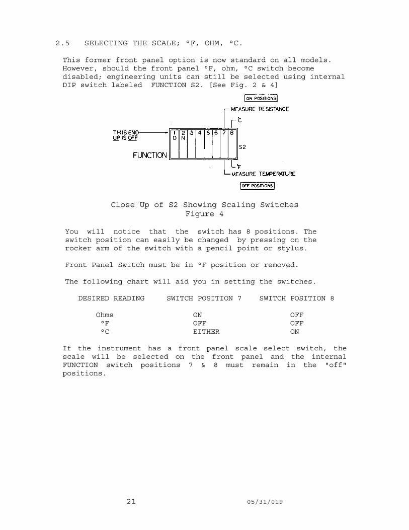
This former front panel option is now standard on all models.However, should the front panel °F, ohm, °C switch becomedisabled; engineering units can still be selected using internalDIP switch labeled FUNCTION S2. [See Fig. 2 & 4]
Close Up of S2 Showing Scaling SwitchesFigure 4
You will notice that the switch has 8 positions. The switch position can easily be changed by pressing on the rocker arm of the switch with a pencil point or stylus.
Front Panel Switch must be in °F position or removed.
The following chart will aid you in setting the switches.
DESIRED READING SWITCH POSITION 7 SWITCH POSITION 8
Ohms ON OFF °F OFF OFF °C EITHER ON
If the instrument has a front panel scale select switch, thescale will be selected on the front panel and the internalFUNCTION switch positions 7 & 8 must remain in the "off"positions.

22 05/31/01
2.6 CHECKSUM VERIFICATION OF PROGRAMMED VARIABLES
The Accu-Temp insures the integrity of the programmed variablesstored in the Zero Power RAM (ZPRAM) by the use of checksums. Thechecksum for each set of variables is programmed into the ZPRAMwhen the set of variables is programmed. Then, each time theinstrument is turned on, the checksum of each set of variables iscomputed and compared to programmed checksum. In the case of anerror, the Accu-Temp displays a message, as below, to indicatewhich set of variables needs to be reprogrammed and waits untilthe variables have been checked.
= Sensor Coefficients for Sensor #1
This indicates there is an error in the Sensor coefficients orthe Zero Offset Correction. The Accu-Temp will display "Prog 1"until FUNCTION switch, position 2 is moved to the ON position.Refer to 2.3.3 of the manual for programming instructions for theSensor Coefficients and 3.1.2 for verification of Zero OffsetCorrection.
NOTE: The Accu-Temp will ignore the setting of the front panelselector switch and will automatically select Sensor #1.
If the Sensor Coefficients and Zero Offset Correction are checkedwithout being reprogrammed, (Refer to 2.4 and 3.1.2.1 of the Accu-Temp manual) both the resistance reading and the temperaturereadings may be incorrect and the "Prog 1" message will bedisplayed the next time the instrument is turned on.
= Sensor Coefficients for Sensor #2
This indicates there is a error in the Sensor Coefficients orthe Zero Offset Correction for Sensor #2. The Accu-Temp willdisplay "Prog 2" until FUNCTION switch, position 2 is moved tothe ON position. Refer to 2.3.3 of the manual for programminginstructions for the Sensor Coefficients and 3.1.2 forverification of Zero Offset Correction.
NOTE: The Accu-Temp will ignore the setting of the front panelselector switch and will automatically select Sensor #2.
If the Sensor Coefficients and Zero offset Corrections arechecked without being reprogrammed, (Refer to 2.4 and3.1.2.1 of the manual) both the resistance reading and thetemperature readings may be incorrect and the "Prog 2"message will be displayed the next time the instrument isturned on.
P r o g 1
P r o g 2

23 05/31/019
= IEEE-488 Interface Address
This indicates there is a problem with the IEEE-488 primary address. The Accu-Temp will display "Prog IEEE" until FUNCTION switch, position 3, is moved to the ON position. Refer to the options manual for programming instructions for the IEEE-488 primary address.
If the primary address is checked without being reprogrammed, the instrument will read resistance and temperature correctly but the interface may not work and the "Prog IEEE" message will be displayed the next time the instrument is turned on.
= RS-232C Interface parameters
This indicates there is a problem with the RS-232C Interface parameters. The Accu-Temp will display "Prog 232" until FUNCTION switch, position 3 is moved to the ON position. Refer to the options manual for programming instructions for the RS-232C interface parameters.
If the parameters are checked without being reprogrammed, the instrument will read resistance and temperature correctly, but the interface may not work and the "Prog 232" message will be displayed the next time the instrument is turned on.
P r o g EEEI
32gorP 2

24 05/31/01
3.0 CALIBRATION PROCEDURES
The Model Accu-Temp Temperature Monitor is calibratedin accordance with the International Temperature Scaleof 1990 (ITS-90). The Accu-Temp conforms to the R vsT tables generated by formulas from the NIST TechnicalNote 1265 within the range of -218 to +660°C.
The instrument is burned-in and factory calibratedprior to shipment. It is designed to remain incalibration for a minimum of one 1 year before arecalibration check is required.
There is only one calibration adjustment and it applies to both channels. This adjustment, if necessary, is performed during the Calibration of Ohmmeter Section (3.1) and is normally made at Full Scale.
3.1 CALIBRATION OF OHMMETER SECTION
Instrument accuracy, as an Ohmmeter, is ±20 PPM or ±0.003 Ohms, whichever is greater.
To verify calibration and linearity, readings should be made at 3 or 4 points, such as:
INSTRUMENT CALIBRATION STANDARDS ACCURACY ACCURACY (3:1 RATIO)
10 Ohms ±0.003 ohms (300ppm) ±0.001 ohms (100ppm) 100 Ohms ±0.003 ohms (30ppm) ±0.001 ohms (10ppm) 200 Ohms ±0.004 ohms (20ppm) ±0.0013 ohms (7ppm) 300 Ohms ±0.006 ohms (20ppm) ±0.002 ohms (7ppm)
Suitable calibration equipment would be:
Resistor Card or Standard Resistors or Decade Resistance Box.
Be sure to use 4 wire connection.
After connections are made, the Accu-Temp should be closed upand allowed to "soak" for a minimum of 45 minutes.

25 05/31/019
3.1.1 FULL SCALE CALIBRATION ADJUSTMENT
If there is a problem at low end calibration, i.e. 10 ohms, there is a "Zero" adjustment available. See Paragraph 3.1.2. This calibration, if required, must be performed before full scale calibration.
R101 is the only analog adjustment and is for full scale or for the highest resistance to which the instrument is used. It adjusts both channels. A clockwise rotation increases the reading.
It is acceptable to calibrate only one channel as they will track each other within ±1 LSD.
When making an adjustment, the top cover should be opened only as long as necessary. After closing the top cover, wait 5 to 10 minutes before taking a new reading.
3.1.2 ZERO OFFSET CORRECTION
This correction is initially made at the factory and should not normally need to be made again, unless U2 is replaced.
MODEL ______________________________S/N_____________
ZERO OFFSET CORRECTION, INPUT 1_______________OHMS
ZERO OFFSET CORRECTION, INPUT 2_______________OHMS
3.1.2.1 VERIFYING CURRENT ZERO OFFSET CORRECTIONS.
First, verify that the factory measured offset corrections are present in memory for each channel.
Refer to general programming procedures in paragraph 2.3.3. After SW #2 of function switch S2 is pushed to ON. Operate SW #4 of S2 to ON. You are now in the Program mode.
Close up of S2 showing Zero OffsetCorrection Programming Switches
Figure 8

26 05/31/01
Operate COEF SELECT pushbutton until menu #7 is displayed by the extreme right hand digit.
This display indicates the Zero Offset Correction that is currently in memory for the input selected. Compare this reading to the listing, if it agrees, check the other input. If it does not agree, adjust it in accordance with paragraph 3.1.2.2. Note that the display gives an extra decade of resolution over what is normally displayed. This menu will not come up if SW #4 of S2 is not ON.
To check the other input, press COEF SELECT until the display reads READY. Operate SW #2 and SW #4 of S2 to OFF. Display commences to read sensor input. Operate input selector switch to the other input. Repeat Paragraph 3.1.2.1.
3.1.2.2 PROGRAMMING NEW ZERO OFFSET CORRECTIONS INTO MEMORY.
For assistance, refer to Paragraph 2.3.3 for general programming procedures. Operate SW #2 & 4 of S2 to ON. Operate CONSTANT SELECT pushbutton until Menu #7 is displayed by the extreme right hand digit.
This display indicates the ZERO OFFSET CORRECTION that is currently in memory for the input selected.
Use the COUNT and DIGIT SELECT pushbuttons to change the display to read the desired numbers. Note that the display gives an extra decade of resolution over what is normally displayed. This menu will not come up if SW #4 of S2 is not ON.
Operate COEF SELECT until the display reads READY.
Operate SW #1 of S2 to ON. Selected values are now being entered into memory.
When display reads DONE, operate SW #1,2 & 4 of S2 to OFF. Instrument will commence reading sensor input.
If the other input is to be done, operate the Input Selector Switch and repeat the procedure.
Full scale calibration should be done after any adjustment to ZERO OFFSET CORRECTION.
7
7

27 05/31/019
3.1.2.3 DETERMINING NEW ZERO OFFSET CORRECTIONS.
If for some reason the offset amount does not appear to be correct, a new offset can be determined. The preferred method is to use a 1 ohm (or alternately 10 ohms) standard
resistor. Adjust the Zero Offset until the instrument reads the 1 ohm (or 10 ohm) Resistor exactly. See Paragraph 3.1.2.2 for programming instructions. Allow 2 to 3 hours of soak time between adjustments. Both channels need to be adjusted. Record new offset corrections with polarity.
An alternate, but less accurate method (by 1 to 2 LSD) is to short the four (4) input terminals together. Adjust the Zero offset until the instrument reads 0.000. See Paragraph 3.1.2.2 for programming instructions. The instrument has a “live” zero and will read negative numbers. Allow a two (2) hour warm-up when using this method. Do both channels. Record new data.
3.2 VERIFYING RESISTANCE TO TEMPERATURE CALCULATIONS
This section of the calibration procedure verifies the microprocessor controlled digital math function.
This Accu-Temp function is not subject to aging or temperature drift, and has no adjustments. It will only calculate erroneously if there is a component failure. Therefore frequent verification is not necessary, if at all.
3.2.1 PROCEDURE OUTLINE
To verify the Accu-Temp math calculations you will need:
A) A Decade Resistance Box with 0.001 ohm resolution. Accuracy is not important in this application.
B) Four wire lead wire.
C) An R vs T Table for a Platinum RTD calculated in accordance with ITS-90 or
D) Use the Sample Math Test listed in this section.
The Accu-Temp will be used to read the resistance of thedecade box.
The instrument calculated temperature is then compared to the temperature obtained from the RvsT table.
If you are using the RvsT table for your sensor, this will also check the programming of the coefficients.

28 05/31/01
3.2.2 PROCEDURE
3.2.2.1 Program the Accu-Temp with the proper coefficientsor the RvsT table that you are using.
3.2.2.2 Disconnect the sensor and connect the Decade Resistance Box.
3.2.2.3 Switch the Accu-Temp to OHMS and adjust theDecade Resistance Box until the instrument reads exactvalue in Ohms of the first selected temperature.
3.2.2.4 Operate "UNITS" Switch to °F and °C. Compareinstrument calculated temperature to the RvsT table. Itshould agree within +0.01°.
3.2.2.5 Repeat for additional points, as desired.
3.2.2.6 When the test is concluded, disconnect theResistance Decade Box and reconnect sensor. Observecorrect terminal markings.
NOTE
If the coefficients were changed for this test, be sure to reprogram the Accu-Temp with the coefficients for the sensor you are currently using.
Close up case and allow for the proper warm-up period.
3.3 SPOT CHECK OF SYSTEM ACCURACY
A simple, but effective, system calibration check can be performed using an Ice Bath.
Periodically immerse the system RTD sensor in a distilled water Ice Bath.
The distilled water Ice Bath may not read exactly 0.000°C but the readings should be consistent from test to test.
While this spot check will not verify full range system accuracy, the constancy of the Ice Bath readings is a
useful indicator of system stability.

29 05/31/019
ITS-90
Accu-Temp MATH TEST
TOLERANCE = ± .01°C or °F
I. 25.5 ohm SPRT
0 = 025.4767 1 = 5-1.1733 2 = 4-1.0562
3 = 7-6.6604 4 = 4-1.6385 5 = 4-5.2488
6 = OPO.0000
OHMS °C °F OHMS °C °F
5.414 ___-190.00 ___-310.00 | 54.589 ___300.00 ___ 572.00
15.146 ___-100.00 ___-148.00 | 63.696 ___400.00 ___ 752.00
25.476 ___ 0.00 ___ 32.00 | 72.507 ___500.00 ___ 932.00
35.483 ___+100.00 ___+212.00 | 81.013 ___600.00 ___1112.00
45.185 ___+200.00 ___+392.00 | 85.967 ___660.00 ___1220.00
___________________________________________________________________
II. 100 ohm PRT
0 = 099.8526 1 = 4-5.1229 2 = 4-1.9492
3 = OPO.0000 4 = 4-5.6753 5 = 4-2.5843
6 = OPO.0000
OHMS °C °F OHMS °C °F
25.620 ___-180.00 ___-292.00 | 177.054 ___200.00 ___392.00
59.384 ___-100.00 ___-148.00 | 213.884 ___300.00 ___572.00
99.849 ___ 0.00 ___ 32.00 | 249.555 ___400.00 ___752.00
139.049 ___ 100.00 ___ 212.00 | 284.060 ___500.00 ___932.00

30 05/31/01
4. THEORY OF OPERATION
The instrument consists of three basic sections:
1. Analog section
2. Analog to Digital section
3. Digital section
ANALOG SECTION
The purpose of the analog section is to convert the resistance of the Platinum RTD into voltages that can be measured by the Analog to Digital Conversion section. This is done by using a current generator to send a nominal 1 mA (on standard model) current through the RTD and an internal reference resistor connected in series (See Fig. 7). The voltage across the RTD (el-e2) is equal to the current (I) times the resistance (RRTD), i.e.
(e1 - e2) = I RRTD
Similarly, (e3 - e4) = I RREF
Since the RTD and the reference resistor are connected in series, the ratio of the voltages will be equal to the ratio of the resistances, i.e.
RRATIO = (e1 - e2) = I RRTD - RRTD
(e3 - e4) I RREF RREF
The reference resistor is adjusted to exactly 100 Ohms so that:
RRATIO = RRTD
100 Ohms

31 05/31/019
Ratio Measuring Technique Figure 9
ANALOG TO DIGITAL CONVERTER SECTION
The purpose of the Analog to Digital Converter section is to transform the analog inputs (e1, e2, e3, and e4) into digital numbers that the Digital section can use to compute the resistance and temperature of the RTD.
Each resistance measurement cycle consists of four conversions, one for each input voltage. Since the computation of the resistance depends on the differences of voltages (e1 - e2 and e3 - e4), any zero-offset errors in the A-to-D Converter will be canceled by the subtraction, as long as the zero-offset does not change significantly during a measurement cycle. Since the computation of the resistance is the ratio of two voltages ([e1 - e2]/[e3 - e4]) a small change in the scale factor of the A-to-D Converter will be divided out, if it does not change significantly during a measurement cycle.

32 05/31/01
The basic accuracy of the instrument is determined by the linearity of the A-to-D Converter and the accuracy and stability of the reference resistor. The dual slope integration technique is used for its excellent linearity and inherent noise rejection. The reference resistor has a low temperature coefficient, less than 1 PPM/°C.
DIGITAL SECTION
The Digital section controls the operation of the A-to-D Converter, computes the resistance and temperature of the RTD, displays the proper engineering units on the front panel, and allows the user to enter and store the coefficients for a particular RTD.
At the end of each measurement cycle, the Digital section computes the resistance of the RTD. It then averages this resistance with the last three readings. If the new resistance differs from the average by less than 7 milliohms, the average is used. If the difference is more than 7 milliohms, then the new reading is used. This technique divides random noise by a factor of 4, but allows the instrument to respond quickly to large changes in resistance.
The temperature is then computed using the formulas from NIST Technical Note 1265 and the coefficients of the RTD being measured. The instrument then display the new read- ing in the selected engineering units.

33 05/31/019
5. TROUBLESHOOTING
The following troubleshooting hints will help you to locate most user associated problems. Please contact the factory if your problem cannot be solved using this guide.
PROBLEM Front Panel "UNITS switch reads only resistance, willnot measure temperature--front panel switch does not
Change scale.
POSSIBLE CAUSE FUNCTION switch set incorrectly--position #7 & 8 should be in "off" position. See section 2.5.
PROBLEM Display reads incorrect scale (°F, ohm , °C) from that desired.
POSSIBLE CAUSE FUNCTION switch set incorrectly, see section 2.5. Instrument is operating in the remote mode, change the instrument back to the local mode.
PROBLEM Instrument was working OK, but suddenly displays erratic unstable readings.
POSSIBLE CAUSE Loose sensor lead.
PROBLEM Display reading drifts down.
POSSIBLE CAUSE Sensor high potential lead is open. (Terminal "+P")
PROBLEM Display reading drifts up.
POSSIBLE CAUSE Sensor low potential lead is open. (Terminal "-p")

34 05/31/01
PROBLEM Display reads "OPEN"
POSSIBLE CAUSE Sensor element is open or either current lead is open.
PROBLEM Temperature readings are incorrect when compared to a known temperature.
POSSIBLE CAUSE Check resistance reading against your R vs T table. If resistance is correct and temperature is incorrect, then and error was made in programming. If both resistance and temperature readings are incorrect, check calibration of the instrument (see section 3). Also check to make sure that the calibration coefficients are for the sensor that you are using. Check for sensor damage by testing in an ice bath.
PROBLEM Instrument works OK, but will not operate from the remote terminal (options 14 & 15).
POSSIBLE CAUSE Loose remote card (see figure 2). Loose wire, connecting remote card to the rear of instrument. Loose or broken interface cable. On RS-232C models (option 14) check Baud rate, word length, parity and stop bit requirements; reprogram if necessary. On IEEE-488 models (option 15) check to make sure the address has been programmed correctly.
PROBLEM Display reads one of the following messages: PROG 1 PROG 2 PROG IEEE PROG 232
POSSIBLE CAUSE These messages mean that a programmed variable has changed. See paragraph 2.7, "Checksum Verification of Programmed Variables".