TE 77 HIGH FREQUENCY FRICTION MACHINE - Phoenix...
30
TE 77 HIGH FREQUENCY FRICTION MACHINE Background The TE 77 High Frequency Friction Machine is a versatile reciprocating tribometer with a maximum stroke of 25 mm and maximum load of 1,000 N. It is now a well-established research and development tool for evaluation of lubricants, materials, coatings and surface treatments.
Transcript of TE 77 HIGH FREQUENCY FRICTION MACHINE - Phoenix...

TE 77 HIGH FREQUENCY FRICTION MACHINE
Background
The TE 77 High Frequency Friction Machine is a versatile reciprocating tribometer with a
maximum stroke of 25 mm and maximum load of 1,000 N. It is now a well-established research
and development tool for evaluation of lubricants, materials, coatings and surface treatments.

With the TE 77, sliding contact conditions can be matched to a number of machine elements.
Specimens may either be of a standard format, or cut from real components, preserving surface
finish and other properties.
The TE 77 was used for the inter laboratory tests for the development of ASTM G 133 “Standard
Test Method for Linearly Reciprocating Ball on Flat Sliding Wear”, which addresses the dry and
lubricated wear of ceramics, metals and ceramic composites and also for ASTM G 181 “Standard
Practice for Conducting Friction Tests of Piston Ring and Cylinder Liner Materials Under
Lubricated Conditions”.
Although not included in the inter laboratory test programs, the TE 77, in conjunction with
selected adapters, can also accommodate tests specimens and provide test conditions as
specified in the following standards:
ASTM D 5706 “Standard Test Method for Determining Extreme Pressure Properties of
Lubricating Grease Using a High Frequency Linear-Oscillating Test Machine”
ASTM D 5707 “Standard Test Method for Measuring Friction and Wear Properties of Lubricating
Grease Using a High Frequency Linear-Oscillating Test Machine”
ISO/DIN 12156-2 “Diesel Fuel Lubricity – Performance Requirement Test Method for Assessing
Fuel Lubricity”
ASTM D 6079 “Standard Test Method for Evaluating Lubricity of Diesel Fuels by the High-
Frequency Reciprocating Rig (HFRR)”
A large body of technical publications from existing users provides information on a wide range
of non-standard research and development test procedures.
Description
TE 77 High Frequency Friction Machine is supplied with its own floor standing bench and with
integral control unit incorporating a SUPERSLIM Serial Link Interface Module, which is connected
to a host PC with COMPEND 2000 sequence control and data acquisition software installed. The
system provides sequence control of load, frequency and temperature plus data acquisition of
measured parameters, at both low and high speed.

Moving Specimen
The moving specimen is mounted in a carrier. A number of different geometries can be
accommodated by using a range of simple clamping fixtures.
6 mm ball carrier in standard sleeve
10 mm ball carrier

6 mm diameter line contact tooling
Self-aligning area contact tooling
The specimen is oscillated mechanically against the fixed lower specimen. The mechanical drive
comprises a motor driven cam and scotch yoke assembly, providing pure sinusoidal motion. The
drive mechanism runs inside an oil bath.
The stroke length is altered manually by adjusting splined eccentric cams on an splined
eccentric shaft. Two fixed cams are provided as standard allowing strokes to be set from 0 to
12.5 mm and 12.5 mm to 25 mm, with a total of eleven discrete positions per cam. A
continuously variable double cam arrangement is included, which allows continuous variation of
the stroke in the range 0 to 12.5 mm.
The moving specimen is loaded against the fixed specimen through a lever mechanism actuated
by a geared servomotor with in-line spring. The normal force is transmitted directly onto the
moving specimen by means of the needle roller cam follower on the carrier head and the
running plate on a loading stirrup. A strain gauge transducer is mounted on the lever at a point
directly beneath the contact and this measures the applied load.
Fixed Specimen
The fixed specimen is located in a stainless steel reservoir. The reservoir is clamped to a block
that is heated by four electrical resistance elements and the temperature is monitored by a
thermocouple pressed against the side of the specimen or holder. The reservoir can be moved
sideways on the heater block so that multiple tests can be performed on one fixed specimen.
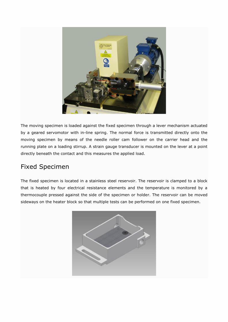
The heater block is mounted on flexures, which are stiff in the vertical (loading) direction, but
offer limited resistance to horizontal forces. Movement in the horizontal direction is resisted by
a piezo-electric force transducer, which measures the friction forces in the oscillating contact.
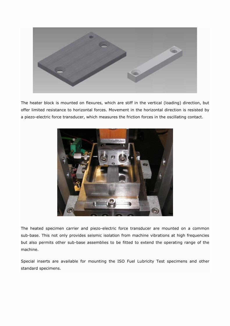
The heated specimen carrier and piezo-electric force transducer are mounted on a common
sub-base. This not only provides seismic isolation from machine vibrations at high frequencies
but also permits other sub-base assemblies to be fitted to extend the operating range of the
machine.
Special inserts are available for mounting the ISO Fuel Lubricity Test specimens and other
standard specimens.

Friction Measurement
The piezo electric transducer used to measure the friction force has a sensitivity of typically
43.5 pC/N and the output range is set to match expected friction levels in the contact. The
maximum friction level is +/- 500 N.
A charge amplifier converts the measured force to a proportional voltage. This is followed by a
low pass filter, which fixes the upper cut off frequency of the measuring system. This serves to
suppress transducer resonance. Final scaling of the signal for voltage output takes place in a
second stage amplifier.
During higher frequency (>1Hz) operation, the charge amplifier is operated a.c. coupled. This
eliminates the effects of d.c. signal drift over long time periods. The signal is passed though a
true rms/dc converter amplifier and the final output is the true mean friction force. The
instantaneous friction signal may also be logged in bursts using the integral high speed data
acquisition interface.
For low frequency sliding (<1Hz), stick-slip, single pass sliding, work with the Energy Pulse
Slide/Roll Adapter and also for calibration of the transducer, the charge amplifier is operated in
Quasi-static d.c. coupled mode. This gives signal decay times of up to 100,000s, sufficiently
long when compared to typical measurement time scales for the zero not to have moved
significantly during the measurement.
Electrical Contact Resistance Measurement
The moving specimen carrier is electrically isolated from the drive shaft and therefore from the
fixed specimen. This allows a millivolt potential to be applied across the contact using a Lunn-
Furey Electrical Contact Resistance Circuit. The voltage signal is taken to a true rms/dc
converter amplifier to give a time-smoothed average of the contact potential.
Variations in this voltage are indicative of the level of metallic contact, provided that both test
specimens are conductors of electricity. This measurement may be used for observing the
formation of chemical films from anti-wear and extreme pressure lubricants, the breakdown of
non-conducting layers and coatings or the build-up of oxides.
The instantaneous value of contact potential is also available for data logging as high speed
data.
Temperature Measurement
Many wear processes are driven by temperature, be they the formation of oxides on the
surfaces, the transformation of microstructure, the formation or break-down of lubricant
additive or other tribochemical films, the melting of the surface (the PV limit of the material) or
thermal stress induced failure.
To be more specific wear occurs as the result of the dissipation of frictional energy in the
contact and this is irresistibly accompanied by a rise in temperature. The frictional energy is
generated by the combination of load and sliding speed and its distribution and dissipation is
influenced by other contacting conditions such as size and relative velocity.
In the reciprocating contact of the TE 77, sliding velocities are deliberately maintained at low
levels in order to minimise frictional heating and, in the case of lubricated tests, to promote
boundary lubrication. Minimisation of frictional heating means that contact temperature can be
controlled effectively by controlling the bulk temperature of the fixed specimen. The
temperature is measured with a thermocouple pressed against the fixed specimen and control is
by software PID with PWM output.
Wear
This is not directly monitored on the TE 77 and assessments are made from wear scar sizes on
the moving specimen and wear volumes on the stationary specimen. Specimen sizes are small
enough to be placed in SEM and other surface analysis equipment for detailed chemical analysis
of surface films.
With the optional TE 77/WEAR fitted, a continuous record can be made of the movement of the
moving specimen relative to the fixed specimen. This measurement can be used as an
indication of the combined wear of both surfaces and for identifying wear transitions.
Control and Data Acquisition
The TE 77 has PC based sequence programmable control and data acquisition. This is provided
by an integrated Serial Link Interface Module and COMPEND 2000 software running on a host
PC, operating under Windows. Data is stored to hard disc in standard spread sheet compatible
file formats (.csv or .tsv).
Sequence Control
Tests are defined by a sequence of steps, each step containing set-point, data recording rates
and alarm level information. Set-points may be adjusted by step change or ramp. The test
sequence is followed unless interrupted by the operator or an alarm. Set-points may also be
adjusted manually using on screen toggles.
Low Speed Data
Analogue input channels are sampled and data logged at a maximum rate of ten samples per
second. Time smoothing and averaging functions are provided by in hardware and software.
RMS Friction
The standard (low data rate) r.m.s. friction signal is generated by passing the input voltage
through a true r.m.s. to d.c. converter. This produces a time smoothed r.m.s. value of the
friction force, integrated over a period of just over 1 second. Because the friction force signal
approximates to a square wave, the r.m.s. friction signal can be considered as an average
friction force as measured over at least one complete cycle, assuming a reciprocating frequency
greater than 1 Hz.
Friction Noise
By rectifying the instantaneous friction force signal and subtracting the r.m.s. average, a
resulting signal corresponding to the perturbations (friction noise) can be produced. If this
signal is subsequently passed through a second true r.m.s. to d.c. converter, an r.m.s. signal of
friction noise can be generated. This can be used, in real time, as an analogue measure of the
friction noise, hence the orderliness or otherwise of the friction signal. By dividing the r.m.s.
friction noise value by the r.m.s. friction signal value, a percentage friction noise value (as a
derived channel in software) can be generated.
High Speed Data
The high speed data acquisition interface provides programmable burst data acquisition of
friction, contact potential and stroke position. It is implemented by means of a 16-bit six
channel multi-function ADC USB card, with programmable data acquisition rates up to 50 kHz.
Data is buffered and stored direct to hard disc with a separate file automatically created for
each acquisition cycle. The high speed data file names are automatically inserted as hyperlinks
in the standard machine data file so that the high speed data may be viewed at the relevant
place in the test.
Comparisons and Advantages
Frequency Range
The maximum frequency on the TE 77 is 50 Hz. It should be noted that the majority of
standards relating to reciprocating tribometers call for a test frequency of 50 Hz or less. The
frequency range of competing electro-magnetic oscillator driven reciprocating tribometers is
often higher (up to 500 Hz), but the amplitude range is lower than the TE 77, with a maximum
stroke range typically up to 4 mm (but not over the full frequency range). This is compared with
25 mm on the standard TE 77. The TE 77 will run at 50 Hz at 5 mm and 30 Hz at 15 mm
stroke.
Whereas stroke length has no great significance for basic tests to evaluate the frictional and
chemical film forming behaviour of lubricants, stroke length, hence sliding distance, are of great
importance when it comes to wear generation. A stroke length of 10 mm is also specified in
ASTM G 133.
Generation of Wear
Wear is a direct function of sliding distance, hence, the rate of generation of wear is a direct
function of the rate of accumulation of sliding distance.
25 mm Stroke at 20 Hz: 60 m per minute (TE 77)
15 mm Stroke at 30 Hz: 54 m per minute (TE 77)
5 mm Stroke at 50 Hz: 30 m per minute (TE 77)
4 mm Stroke at 50 Hz: 24 m per minute (Typical electro-magnetic machine
performance)
1 mm Stroke at 100 Hz: 12 m per minute (Typical electro-magnetic machine
performance)
The longer stroke capability of the TE 77 makes it a more effective wear generator than short
stroke electro magnetically driven devices. It also allows tests to be performed using variable
contact width, hence variable contact pressure, curved edge fixed specimens.
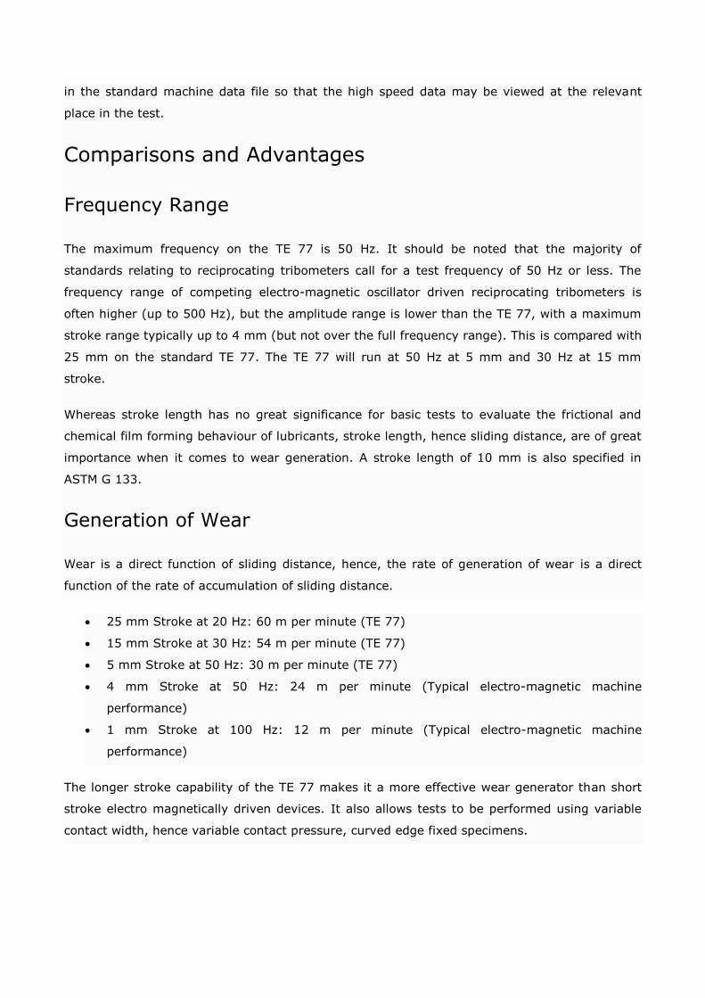
Entrainment and Wear Debris
The ability of the moving specimen to “expose” all parts of the fixed specimen depends on the
contact length being not more than half the stroke length. In other words, in the case of other
devices, with a contact length greater than 2 mm and a maximum stroke of 4 mm, it is
apparent that the centre portion of the fixed specimen will be in continuous contact with part of
the moving specimen. This has serious implications for lubricant entrainment, for surface
activation and for the discharge of wear debris from the contact. Debris can become entrapped
and generate an unwanted third body wear mechanism. Because of this, the devices are not
entirely satisfactory for adhesive wear tests with area contact specimens.
Contact Scale
An important issue with regard to contact scale is how the wear is shared between the two
contacting surfaces. Wear is a function of sliding distance. In the case of the moving specimen,
the sliding distance is twice the stroke length x number of cycles. For a point on the fixed
specimen, the linear wear is twice the contact length x number of cycles. In other words, the
wear of the moving specimen is dependent on total sliding distance but the wear on the fixed
specimen is dependent on the number of passes and the contact length. It follows that the ratio
of wear between the two surfaces depends on both stroke and contact length. In order to model
a real tribological contact, this contact scale parameter should be correctly modelled.
To get the model right, the contact length must be correctly scaled. Hence, running at 25 mm
stroke modelling a contact length of 3 mm in an engine with 100 mm stroke, the ring specimen
in the test machine should have a contact length of 0.75 mm. To model this at shorter stroke
lengths would require a contact length of 0.09 mm, which is not practical.
The extra stroke length on the TE 77 means that quite a variety of large sliding specimens can
be accommodated. This is particularly useful when working with test specimens cut from
machine components. The test area is highly accessible and open to design of specialised
specimen carriers.
Very Low Frequencies
The TE 77 offers, by means of simple interchangeable gearboxes, a minimum frequency down
to 0.01 Hz. Electro magnetically driven devices typically offer a minimum operating frequency of
1 Hz. This lower end speed range allows the TE 77 machine to be used for investigating stick-
slip and friction-velocity (Stribeck) curve characteristics of lubricants and materials.
Optional Accessories
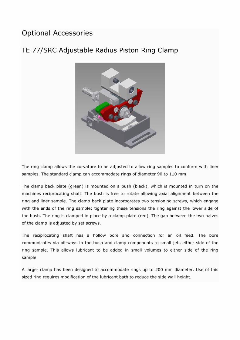
TE 77/SRC Adjustable Radius Piston Ring Clamp
The ring clamp allows the curvature to be adjusted to allow ring samples to conform with liner
samples. The standard clamp can accommodate rings of diameter 90 to 110 mm.
The clamp back plate (green) is mounted on a bush (black), which is mounted in turn on the
machines reciprocating shaft. The bush is free to rotate allowing axial alignment between the
ring and liner sample. The clamp back plate incorporates two tensioning screws, which engage
with the ends of the ring sample; tightening these tensions the ring against the lower side of
the bush. The ring is clamped in place by a clamp plate (red). The gap between the two halves
of the clamp is adjusted by set screws.
The reciprocating shaft has a hollow bore and connection for an oil feed. The bore
communicates via oil-ways in the bush and clamp components to small jets either side of the
ring sample. This allows lubricant to be added in small volumes to either side of the ring
sample.
A larger clamp has been designed to accommodate rings up to 200 mm diameter. Use of this
sized ring requires modification of the lubricant bath to reduce the side wall height.

TE 77/TRC Adjustable Radius Twin Piston Ring Clamp
This arrangement allows two adjustable radius ring clamps to be mounted in series so that tests
can be run with two ring samples on a common liner section sample.
TE 77/PT Pin on Twin Test Bath
The pin on twin test bath allows tests to be performed with a self-locating crossed cylinder
geometry. This is a technique originally developed by Dr Peter Blau at Oakridge National
Laboratories.
TE 77/WEAR On-Line Wear Monitoring System
TE 77/WEAR is a high-resolution capacitance proximity measuring system. Output from the
device is in the form of a DC voltage proportional to displacement, suitable for data acquisition
on a PC.
A capacitance non-contact probe is mounted in the moving specimen carrier. The probe is
mounted approximately 0.5 mm away from a reference surface mounted on the edge of the
specimen bath. The capacitance of the gap is converted to a dc voltage by a charge amplifier.
The voltage is passed through a true rms/dc converter to provide the mean gap value over the
length of the stroke.
The variations in the gap due to wear, lubricant film formation, thermal expansion or a
combination of these are picked up by the system. The fact that the gap is small ensures that
temperature effects are limited to the thermal expansion over that length.
The measuring resolution is greatest when the temperature of the fixed specimen is held
constant. The TE 77/WEAR system is ideal for establishing long-term wear rates and transition
points.
TE 77/GB/20 Gearbox for 20:1
This gearbox mounts between the drive motor and camshaft, providing a 20:1 reduction in
operating frequency. The low sliding speeds generated encourage the contact to operate in
boundary lubrication conditions. The option is therefore useful when testing additives and
lubricant formulations.
TE 77/GB/100 Gearbox for 100:1 Reduction
This gearbox mounts between the drive motor and camshaft, providing a 100:1 reduction in
operating frequency. The very low sliding speeds generated ensure that the contact operates in
boundary lubrication conditions. The option is used for studying static friction and stick-slip of
lubricants for slide-ways, clutches and the like. Specimens are available for stick-slip testing.
TE 77/HR Heated Piston Ring Sample Carrier
The TE 77/HR is a replacement reciprocating specimen carrier with integral heating, designed to
allow tests to be run with a differential temperature between the moving ring specimen and the
fixed liner specimen. The ring sample is self-heating to 200°C and is normally used in

conjunction with liner sample temperature controlled by the fixed specimen heater block to less
than this value.
TE 77/INERT Gas Enclosure
The TE 77/INERT Gas Enclosure is an anodised aluminium chamber that fits in place of the
standard heater bath and encloses the fixed and moving specimens. The reciprocating specimen
carrier is sealed by a rubber bellows fitted between the reciprocating drive assembly and the
chamber. Load is applied through a flexible membrane in the top of the chamber.
Inlet and outlet pipe fittings and a length of pipe are provided for connection to a customer’s
inert gas supply. A water manometer is used to measure the gas pressure in the enclosure.
Specimen temperatures in the chamber are limited to 200°C.
This option is used for investigating the effects of ambient gas or moisture on friction and wear.
Inert gases, water vapour and mildly corrosive gases may be used.

TE 77/COOLER
This replaces the standard fixed specimen heater block assembly with a cooler pad. A laboratory
refrigeration unit delivers pressurised refrigerant direct to an expansion probe, embedded in the
cooler pad, removing the requirement for an intermediate heat transfer fluid. This arrangement
allows temperatures from ambient to -50°C to be achieved. To avoid ice formation, a test
enclosure is included, fed with cool and dry air, delivered via a vortex cooler and a desiccant
tube. A compressed air supply is required.
TE 77/800C High Temperature Heater
On the TE 77 the heated specimen carrier and piezo-electric force transducer are mounted on a
common sub-base. To carry out high temperature experiments this is replaced with the
separate TE 77/800C sub-base assembly. Key components of this assembly are made from
Inconel (for high temperature performance) and a thermal barrier ensures that the flexures and
piezo-electric force transducer are not exposed to excessive temperature.
The standard reciprocating specimen carrier head is also replaced by a carrier made from
Inconel. This has a “C” shape, permitting the specimens to be enclosed inside a shroud and the
load to be transmitted through a roller bearing outside this enclosure.
Specimens can be mounted either in the standard sample bath for dry or lubricated tests up to
600°C or on a special platform for high temperature un-lubricated tests. A stainless steel shroud
is provided to help reduce heat loss by radiation and convection at the high temperatures.

This option may be provided as a retrofit assembly comprising heater block and four 200 W
heaters, flexures and piezo-electric force transducer all mounted on a separate sub-base. The
heaters are wired into the same connector as the standard heaters once these have been
removed.
TE 77/PUMP Peristaltic Pump and Drip Feed System
The TE 77/PUMP drip feed system uses a variable speed peristaltic pump. The advantages of
this system are that there is no cross-contamination between pump and fluid, fluids are not
exposed to high shear rates, it is self-priming and safe under dry running. By selecting a range
of tube bore diameters a very wide range of flow rates are achievable. With a single size of tube
the pump has a 110:1 turn ratio.
The package includes the peristaltic pump controller and pump head, three sizes of pump tubing
and universal pipe fittings. An adaptor is provided for use with the standard moving specimen
carrier clamps. This allows a PTFE tube to be mounted on the carrier to direct lubricant onto the
contact zone.
This option is used in additives screening and lubricant development programs to provide fresh
lubricant to the contact over long time periods. This is particularly important if tests are being
carried out at temperatures where oxidation or evaporation of the sample is accelerated.
TE 77/PIEZO Fretting Test Adapter
This adapter replaces the standard reciprocating drive assembly with a piezo actuator drive
system. This is for performing fretting tests at strokes from 10 to 100 microns with frequencies
up to 100 Hz with control of mid-stroke position and amplitude to +/-0.2 microns.
The system includes a high pre-load piezostack, servo amplifier and signal generator,
capacitance displacement gauge, 250 kHz 16-bit 16 channel multi-function ADC (not required if
TE 77/HSD is already installed) and C-flex mounted moving specimen carrier. Simultaneous
high speed data acquisition of friction force and displacement allows force-displacement curves
to be plotted.
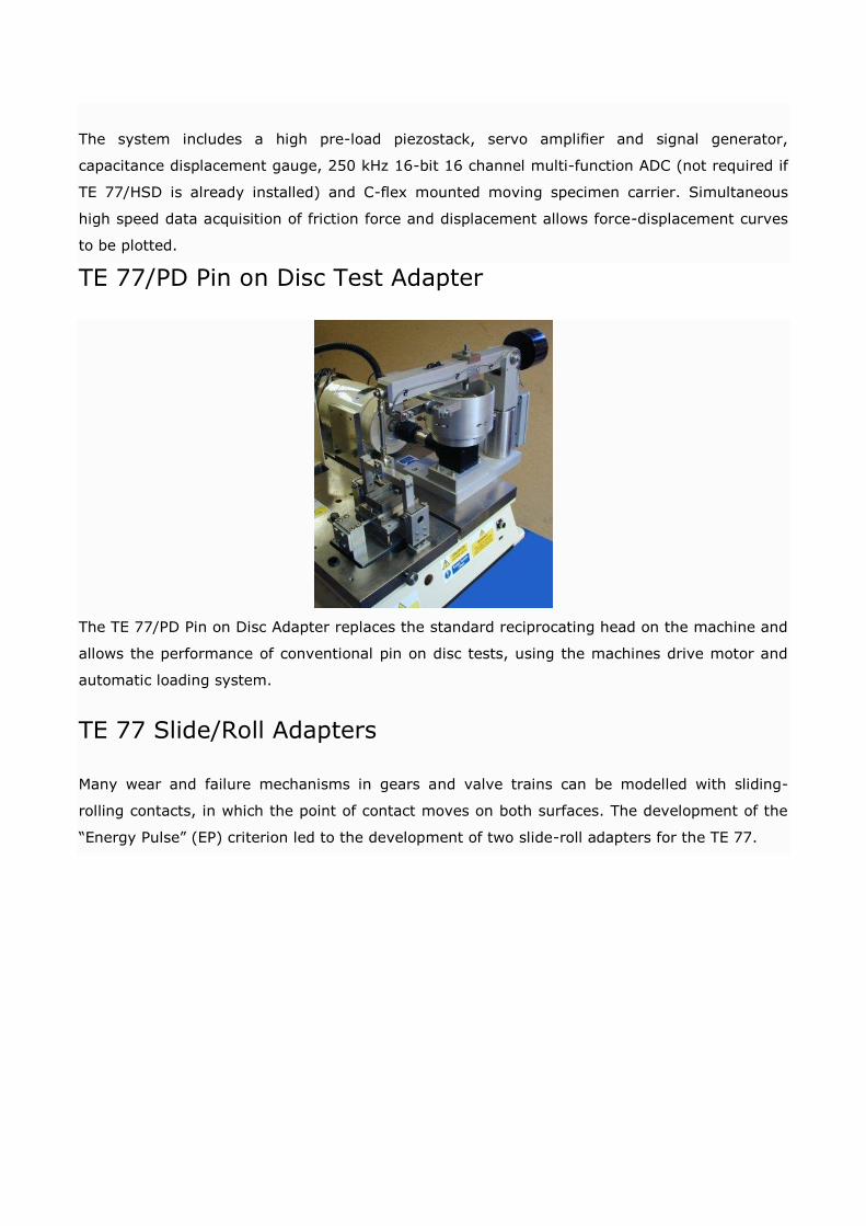
TE 77/PD Pin on Disc Test Adapter
The TE 77/PD Pin on Disc Adapter replaces the standard reciprocating head on the machine and
allows the performance of conventional pin on disc tests, using the machines drive motor and
automatic loading system.
TE 77 Slide/Roll Adapters
Many wear and failure mechanisms in gears and valve trains can be modelled with sliding-
rolling contacts, in which the point of contact moves on both surfaces. The development of the
“Energy Pulse” (EP) criterion led to the development of two slide-roll adapters for the TE 77.

TE 77 EP-CAM
In this arrangement, a plate specimen is reciprocated against a rotating roller in what has been
termed a “Reciprocating Amsler” test configuration. This produces asymmetrical lubricant
entrainment: positive with the surface of the plate and roller moving in the same direction and,
depending on relative speeds, negative when moving in opposite directions, hence a model for
the kind of entrainment conditions occurring in a cam-follower contact. No point on either
specimen remains in continuous contact.
The adapter uses the standard 25 mm stroke cam drive and loading system. It is supplied on an
sub-base, interchangeable with the standard TE 77 heated specimen carrier and piezo-electric
force transducer sub-base. The TE 77/EP-CAM test roller is mounted on the output shaft of a
worm gearbox and runs in a heated lubricant reservoir. The reservoir is supported on flexures
and a piezo-electric force transducer measures the horizontal (traction) forces in the contact.
The enclosure is provided with an integral electric heater and thermocouple to enable tests with
bulk fluid temperatures up to 100°C.
The worm gearbox with has a 2:1 speed reduction and the input shaft is connected via a 1:2
ratio bevel gearbox to a servo-motor. The rotational speed of the roller can be adjusted
independently of the reciprocating rate of the plate, allowing a range of different varying
entrainment velocities to be set. In addition to adjusting the varying slide/roll ratio by adjusting
the rotational speed and reciprocating frequency, the stoke length can of course be adjusted.
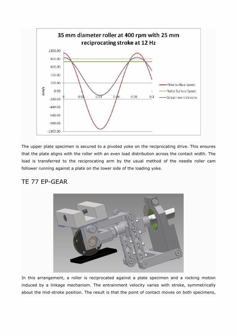
The upper plate specimen is secured to a pivoted yoke on the reciprocating drive. This ensures
that the plate aligns with the roller with an even load distribution across the contact width. The
load is transferred to the reciprocating arm by the usual method of the needle roller cam
follower running against a plate on the lower side of the loading yoke.
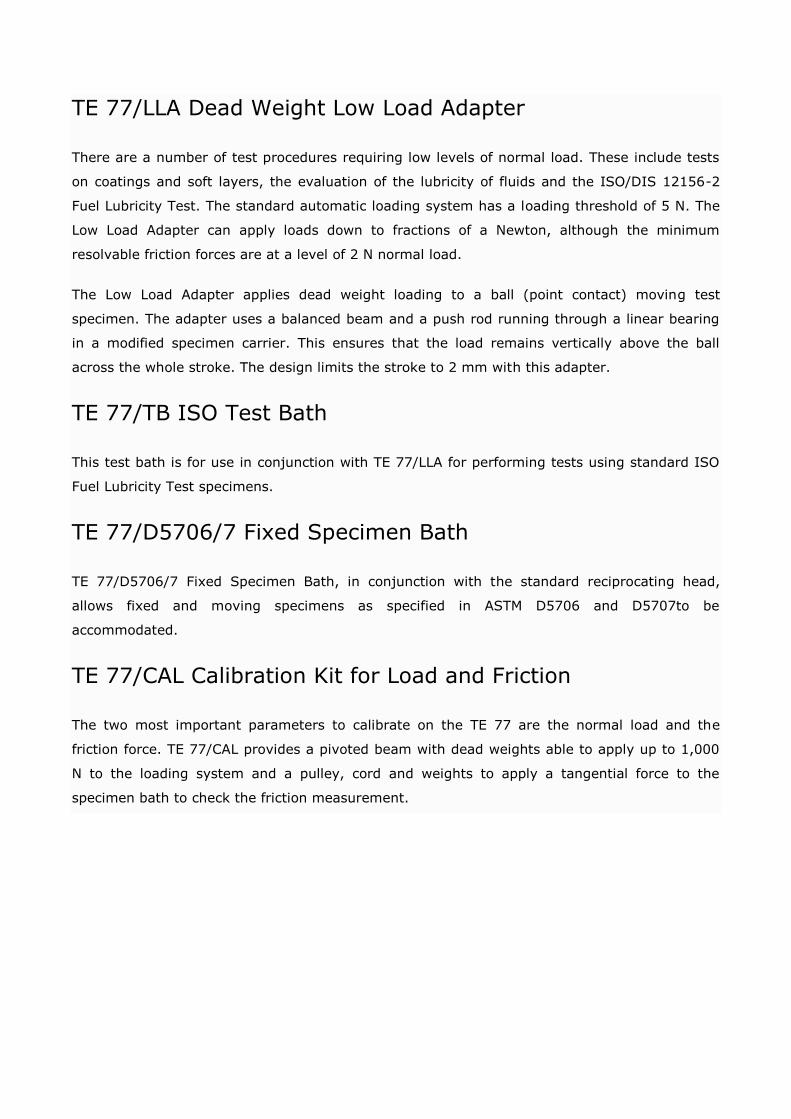
TE 77 EP-GEAR
In this arrangement, a roller is reciprocated against a plate specimen and a rocking motion
induced by a linkage mechanism. The entrainment velocity varies with stroke, symmetrically
about the mid-stroke position. The result is that the point of contact moves on both specimens,

similar to gear teeth sliding and rolling about the pitch point. No point on either specimen
remains in continuous contact.
The adapter replaces the standard machine reciprocating head and thus uses the standard 25
mm stroke cam drive, loading system and fixed specimen assembly. Slide-roll ratio is adjusted
by altering the position of the link arms.
TE 77/LLA Dead Weight Low Load Adapter
There are a number of test procedures requiring low levels of normal load. These include tests
on coatings and soft layers, the evaluation of the lubricity of fluids and the ISO/DIS 12156-2
Fuel Lubricity Test. The standard automatic loading system has a loading threshold of 5 N. The
Low Load Adapter can apply loads down to fractions of a Newton, although the minimum
resolvable friction forces are at a level of 2 N normal load.
The Low Load Adapter applies dead weight loading to a ball (point contact) moving test
specimen. The adapter uses a balanced beam and a push rod running through a linear bearing
in a modified specimen carrier. This ensures that the load remains vertically above the ball
across the whole stroke. The design limits the stroke to 2 mm with this adapter.
TE 77/TB ISO Test Bath
This test bath is for use in conjunction with TE 77/LLA for performing tests using standard ISO
Fuel Lubricity Test specimens.
TE 77/D5706/7 Fixed Specimen Bath
TE 77/D5706/7 Fixed Specimen Bath, in conjunction with the standard reciprocating head,
allows fixed and moving specimens as specified in ASTM D5706 and D5707to be
accommodated.
TE 77/CAL Calibration Kit for Load and Friction
The two most important parameters to calibrate on the TE 77 are the normal load and the
friction force. TE 77/CAL provides a pivoted beam with dead weights able to apply up to 1,000
N to the loading system and a pulley, cord and weights to apply a tangential force to the
specimen bath to check the friction measurement.
TE 77 HIGH FREQUENCY FRICTION MACHINE
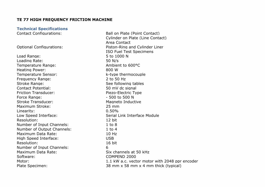
Technical Specifications Contact Configurations: Ball on Plate (Point Contact)
Cylinder on Plate (Line Contact)Area Contact
Optional Configurations: Piston-Ring and Cylinder LinerISO Fuel Test Specimens
Load Range: 5 to 1000 NLoading Rate: 50 N/sTemperature Range: Ambient to 600°CHeating Power: 800 WTemperature Sensor: k-type thermocoupleFrequency Range: 2 to 50 HzStroke Range: See following tablesContact Potential: 50 mV dc signalFriction Transducer: Piezo-Electric TypeForce Range: - 500 to 500 NStroke Transducer: Magneto InductiveMaximum Stroke: 25 mmLinearity: 0.50%Low Speed Interface: Serial Link Interface ModuleResolution: 12 bitNumber of Input Channels: 1 to 8Number of Output Channels: 1 to 4Maximum Data Rate: 10 HzHigh Speed Interface: USBResolution: 16 bitNumber of Input Channels: 6Maximum Data Rate: Six channels at 50 kHzSoftware: COMPEND 2000Motor: 1.1 kW a.c. vector motor with 2048 ppr encoderPlate Specimen: 38 mm x 58 mm x 4 mm thick (typical)
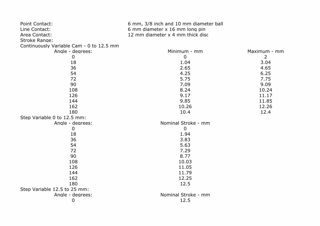
Point Contact: 6 mm, 3/8 inch and 10 mm diameter ballLine Contact: 6 mm diameter x 16 mm long pinArea Contact: 12 mm diameter x 4 mm thick discStroke Range:Continuously Variable Cam - 0 to 12.5 mm
Angle - degrees: Minimum - mm Maximum - mm0 0 218 1.04 3.0436 2.65 4.6554 4.25 6.2572 5.75 7.7590 7.09 9.09108 8.24 10.24126 9.17 11.17144 9.85 11.85162 10.26 12.26180 10.4 12.4
Step Variable 0 to 12.5 mm:Angle - degrees: Nominal Stroke - mm
0 018 1.9436 3.8354 5.6372 7.2990 8.77108 10.03126 11.05144 11.79162 12.25180 12.5
Step Variable 12.5 to 25 mm:Angle - degrees: Nominal Stroke - mm
0 12.5
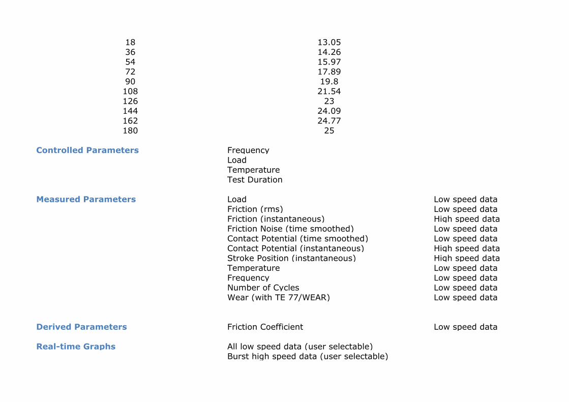
18 13.0536 14.2654 15.9772 17.8990 19.8108 21.54126 23144 24.09162 24.77180 25
Controlled Parameters FrequencyLoadTemperatureTest Duration
Measured Parameters Load Low speed dataFriction (rms) Low speed dataFriction (instantaneous) High speed dataFriction Noise (time smoothed) Low speed dataContact Potential (time smoothed) Low speed dataContact Potential (instantaneous) High speed dataStroke Position (instantaneous) High speed dataTemperature Low speed dataFrequency Low speed dataNumber of Cycles Low speed dataWear (with TE 77/WEAR) Low speed data
Derived Parameters Friction Coefficient Low speed data
Real-time Graphs All low speed data (user selectable)Burst high speed data (user selectable)
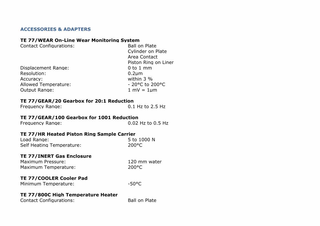
ACCESSORIES & ADAPTERS
TE 77/WEAR On-Line Wear Monitoring SystemContact Configurations: Ball on Plate
Cylinder on PlateArea ContactPiston Ring on Liner
Displacement Range: 0 to 1 mmResolution: 0.2µmAccuracy: within 3 %Allowed Temperature: - 20°C to 200°COutput Range: 1 mV = 1µm
TE 77/GEAR/20 Gearbox for 20:1 ReductionFrequency Range: 0.1 Hz to 2.5 Hz
TE 77/GEAR/100 Gearbox for 1001 ReductionFrequency Range: 0.02 Hz to 0.5 Hz
TE 77/HR Heated Piston Ring Sample CarrierLoad Range: 5 to 1000 NSelf Heating Temperature: 200°C
TE 77/INERT Gas EnclosureMaximum Pressure: 120 mm waterMaximum Temperature: 200°C
TE 77/COOLER Cooler PadMinimum Temperature: -50°C
TE 77/800C High Temperature HeaterContact Configurations: Ball on Plate

Cylinder on PlateArea Contact
Plate Size: 30 mm diameter x 4 mm thickTemperature Range: ambient to 800°CHeating Power: 800 WTemperature Sensor: k-type thermocouple
TE 77/PUMP Peristaltic Pump and Drip FeedMaximum Pump Speed: 55 rpmTurn-Down Ratio: 110:01:00Flow Rates: 0.02 to 2.3 ml/min with 0.5 mm bore tube
0.06 to 6.7 ml/min with 0.8 mm bore tube0.22 to 24 ml/min with 1.6 mm bore tube
Tube Wall Thickness: 1 mm
TE 77/PIEZO Fretting Test AdapterType of Contact: Ball/Flat
Flat/FlatLine/Flat
Type of Movement: Sine, Square and TriangularLoad: 5 to 1000 NFriction Force: +/-500 N MaximumStroke - continuously variable: 10 microns to 100 micronsResolution: +/-0.2 micronsFrequency – continuously variable: 1 Hz to 100 HzMaximum stroke at 100 Hz: 30 micronsMaximum stroke at 50 Hz: 60 micronsMaximum stroke at 20 Hz: 100 microns
TE 77/PD Pin on Disc AdapterContact Configurations: Pin on Disc
Ball on DiscSpecimen Holders: 8 mm and 5.5 mm diameter pins
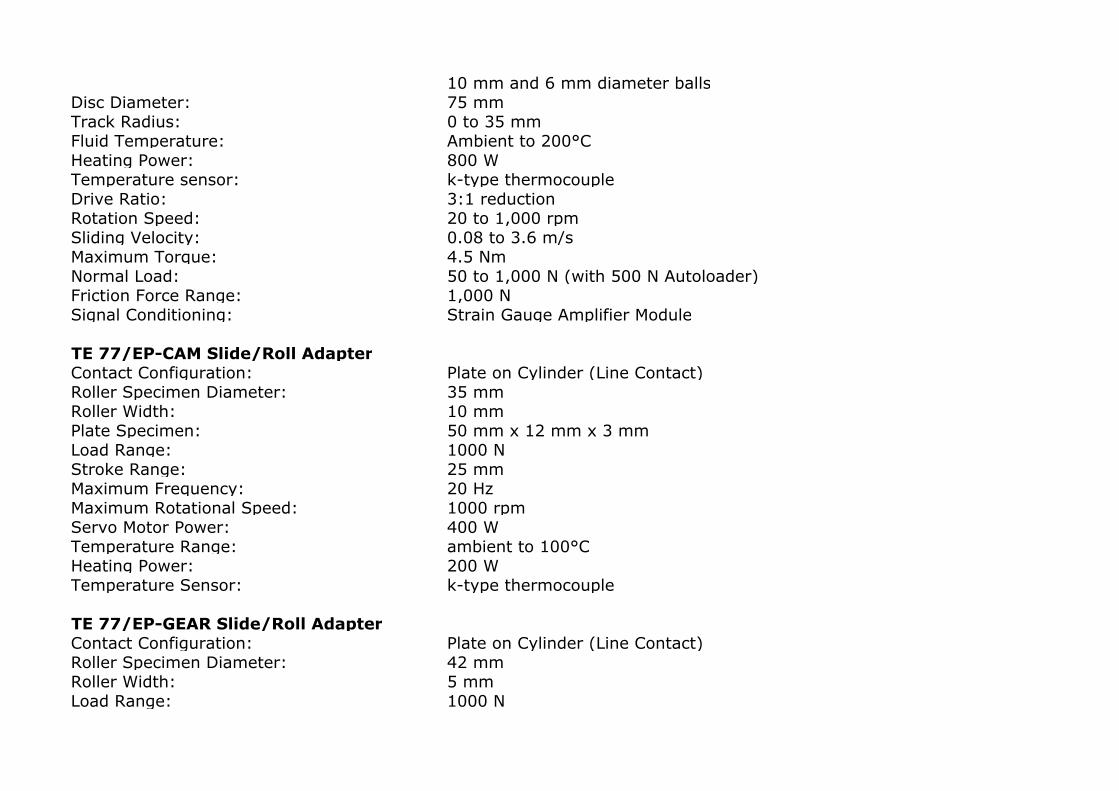
10 mm and 6 mm diameter ballsDisc Diameter: 75 mmTrack Radius: 0 to 35 mmFluid Temperature: Ambient to 200°CHeating Power: 800 WTemperature sensor: k-type thermocoupleDrive Ratio: 3:1 reductionRotation Speed: 20 to 1,000 rpmSliding Velocity: 0.08 to 3.6 m/sMaximum Torque: 4.5 NmNormal Load: 50 to 1,000 N (with 500 N Autoloader)Friction Force Range: 1,000 NSignal Conditioning: Strain Gauge Amplifier Module
TE 77/EP-CAM Slide/Roll AdapterContact Configuration: Plate on Cylinder (Line Contact)Roller Specimen Diameter: 35 mmRoller Width: 10 mmPlate Specimen: 50 mm x 12 mm x 3 mmLoad Range: 1000 NStroke Range: 25 mmMaximum Frequency: 20 HzMaximum Rotational Speed: 1000 rpmServo Motor Power: 400 WTemperature Range: ambient to 100°CHeating Power: 200 WTemperature Sensor: k-type thermocouple
TE 77/EP-GEAR Slide/Roll AdapterContact Configuration: Plate on Cylinder (Line Contact)Roller Specimen Diameter: 42 mmRoller Width: 5 mmLoad Range: 1000 N

Stroke Range: 25 mmMaximum Frequency: 10 Hz
TE 77/LLA Dead Weight Low Load AdapterContact Configuration: Ball on PlateBall Diameter: 6 mmLoad Range: 2 to 20 N by dead weightAllowed Stroke: 0 to 2 mmMaximum Frequency: 50 Hz
TE 77/D5706/7 Specimen BathSpecimen: 24 mm Diameter x 7.85 mm Specimen (ASTM D5706/7)
ServicesElectricity: 220/240 V, single phase, 50/60 Hz, 3.2 kW
InstallationFloor-standing machine: 900 mm x 900 mm x 600 mm high, 250 kgPacking Specifications: 1.33 m3, GW 410 kg, NW 310 kg