TDT4255 Computer Design Review Lecture Magnus Jahre · TDT4255 Computer Design. Review Lecture ....
83
1 TDT4255 – Computer Design TDT4255 Computer Design Review Lecture Magnus Jahre
Transcript of TDT4255 Computer Design Review Lecture Magnus Jahre · TDT4255 Computer Design. Review Lecture ....

1
TDT4255 – Computer Design
TDT4255 Computer Design Review Lecture Magnus Jahre

2
TDT4255 – Computer Design
ABOUT THE EXAM

3
TDT4255 – Computer Design
About exam • The exam will cover a large part of the curriculum
(reading list) • Exam properties that we seek:
– Comprehensible and unambiguous – Correct – Reasonable (e.g. not too easy, not too difficult, not ask about
unimportant details but rather try to focus on principles and understanding, etc.)
– Relevant (same as above) – Differentiating (NTNU has decided that an 'A' should be an
outstanding result, and we need to have some difficult questions to be able to find eventual A-candidates and to get a reasonable distribution of the students among the possible marks.)
– Unpredictable (We think it should not be given information or answers to questions that are of a kind that makes it possible for smart or pushing students to find out what the exam will include or not. We want to influence the students so that they prepare for the exam by trying to maximize the learning of the course material rather than by speculation :-) ).

4
TDT4255 – Computer Design
How to Answer an Exam Question • Only answer what is asked for
– No points awarded for answers that are besides the point
• Only answer what you are reasonably sure is correct
– Norwegian saying: ”It’s better to keep you mouth shut and let people think you are stupid than to open your mouth and remove all doubt.”
• There is a limited amount of space available to
answer the questions – Prioritize: good priorities indicate good understanding
5
TDT4255 – Computer Design
Example Assignment (1/2)
• Explain the difference between a write-through and a write-back strategy for caches
• Good answer: – A write-through strategy updates main memory on all cache writes – A write-back strategy writes back dirty data when the block is
evicted from the cache
• Why is this good?
– Answers the question – Only answers the question
6
TDT4255 – Computer Design
Example Assignment (2/2) • Explain the difference between a write-through and a
write-back strategy for caches
• Poor answer: – A write-through strategy updates main memory on all cache writes – A write-back strategy writes back dirty data when the block is
evicted from the cache – Set associative caches are common in current processors – Fully associative caches are popular because they give the lowest
miss rates – (the answer continues with any possible irrelevant facts about
caches where some are correct and others are wrong or at least imprecise)
Not asked for! Imprecise!

7
TDT4255 – Computer Design
Other Practicalities
• The exam will have multiple choice – Trade off: hard to write vs. easy to grade
• MIPS fact sheet will be provided
• Last years exam available on it’s learning – ... but no solution – The questions can have “many” correct answers

8
TDT4255 – Computer Design
Chapter 1 Review
Acknowledgement: Slides are adapted from Morgan Kaufmann companion material
9
TDT4255 – Computer Design
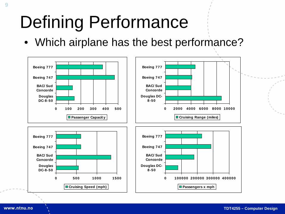
Defining Performance • Which airplane has the best performance?
0 100 200 300 400 500
DouglasDC-8-50
BAC/SudConcorde
Boeing 747
Boeing 777
Passenger Capacity
0 2000 4000 6000 8000 10000
Douglas DC-8-50
BAC/SudConcorde
Boeing 747
Boeing 777
Cruising Range (miles)
0 500 1000 1500
DouglasDC-8-50
BAC/SudConcorde
Boeing 747
Boeing 777
Cruising Speed (mph)
0 100000 200000 300000 400000
Douglas DC-8-50
BAC/SudConcorde
Boeing 747
Boeing 777
Passengers x mph
10
TDT4255 – Computer Design
Response Time and Throughput • Book definition: Time from issuing a command to its completion
– This is often referred to as the turn-around time
• More common response time definition: Time from issue to first response
• Execution time is the time the processor is busy execution the program – Turn-around time includes the time the process waits to be
executed, execution time does not – Also: user execution time vs. system execution time
• Throughput is the total work per unit time
11
TDT4255 – Computer Design
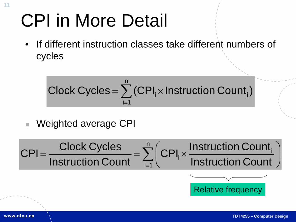
CPI in More Detail • If different instruction classes take different numbers of
cycles
∑=
×=n
1iii )Count nInstructio(CPICycles Clock
Weighted average CPI
∑=
×==
n
1i
ii Count nInstructio
Count nInstructioCPICount nInstructio
Cycles ClockCPI
Relative frequency
12
TDT4255 – Computer Design
Appendix D Review
Acknowledgement: Slides are adapted from Morgan Kaufmann companion material
13
TDT4255 – Computer Design
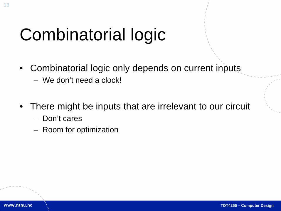
Combinatorial logic
• Combinatorial logic only depends on current inputs – We don’t need a clock!
• There might be inputs that are irrelevant to our circuit
– Don’t cares – Room for optimization
14
TDT4255 – Computer Design
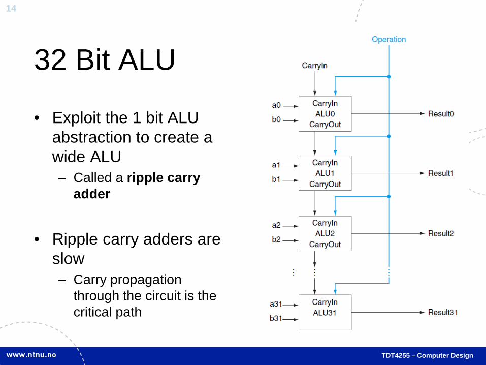
32 Bit ALU
• Exploit the 1 bit ALU abstraction to create a wide ALU – Called a ripple carry
adder
• Ripple carry adders are slow – Carry propagation
through the circuit is the critical path
15
TDT4255 – Computer Design
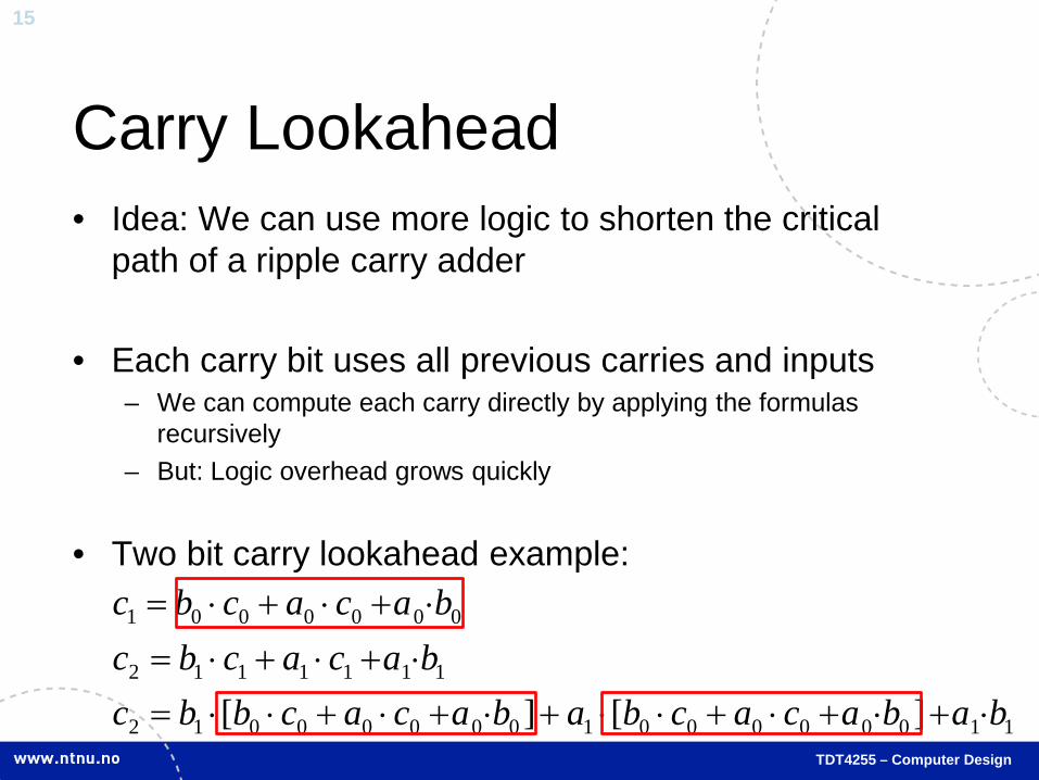
Carry Lookahead • Idea: We can use more logic to shorten the critical
path of a ripple carry adder
• Each carry bit uses all previous carries and inputs – We can compute each carry directly by applying the formulas
recursively – But: Logic overhead grows quickly
• Two bit carry lookahead example:
11000000100000012
1111112
0000001
][][ babacacbabacacbbcbacacbcbacacbc
⋅+⋅+⋅+⋅⋅+⋅+⋅+⋅⋅=⋅+⋅+⋅=⋅+⋅+⋅=
16
TDT4255 – Computer Design
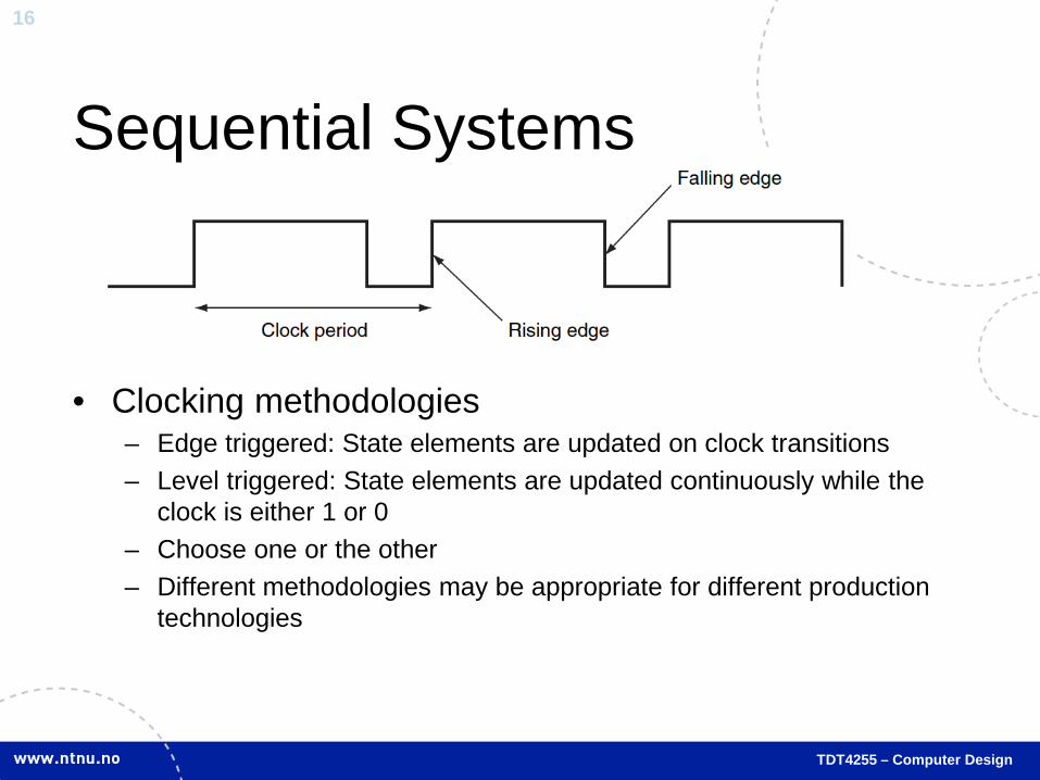
Sequential Systems
• Clocking methodologies – Edge triggered: State elements are updated on clock transitions – Level triggered: State elements are updated continuously while the
clock is either 1 or 0 – Choose one or the other – Different methodologies may be appropriate for different production
technologies

17
TDT4255 – Computer Design
Register
• Collection of flip-flops or latches that store multi-bit values
• Register files contain multiple registers and access logic
reg: process(clk)
begin
if rising_edge(clk) then
data_out <= data_in_1;
end if;
end process reg;
VHDL code is identical to latch/flip-flop except that the signals are vectors and not
scalars

18
TDT4255 – Computer Design
Register File Example
2 Port Read logic 1 Port Write logic

19
TDT4255 – Computer Design
Finite State Machines
• Commonly synchronous – Changes state on clock
tick
• Two types – Moore: Next state only
depends on current state – Mealy: Next state
depends on current state and inputs
Moore or Mealy?
Almost all electronic systems contain a number of state machines

20
TDT4255 – Computer Design
Chapter 2 Review
Acknowledgement: Slides are adapted from Morgan Kaufmann companion material

21
TDT4255 – Computer Design
Instruction Set Design • DP1: Simplicity favors regularity
– Regularity makes implementation simpler – Simplicity enables higher performance at lower cost
• DP2: Smaller is faster
• DP3: Make the common case fast
– Small constants are common – Immediate operand avoids a load instruction
• DP4: Good design demands good compromises
– Different formats complicate decoding, but allow 32-bit instructions uniformly – Keep formats as similar as possible

22
TDT4255 – Computer Design
MIPS R-format Instructions
• Instruction fields – op: operation code (opcode) – rs: first source register number – rt: second source register number – rd: destination register number – shamt: shift amount (00000 for now) – funct: function code (extends opcode)
op rs rt rd shamt funct 6 bits 6 bits 5 bits 5 bits 5 bits 5 bits
23
TDT4255 – Computer Design
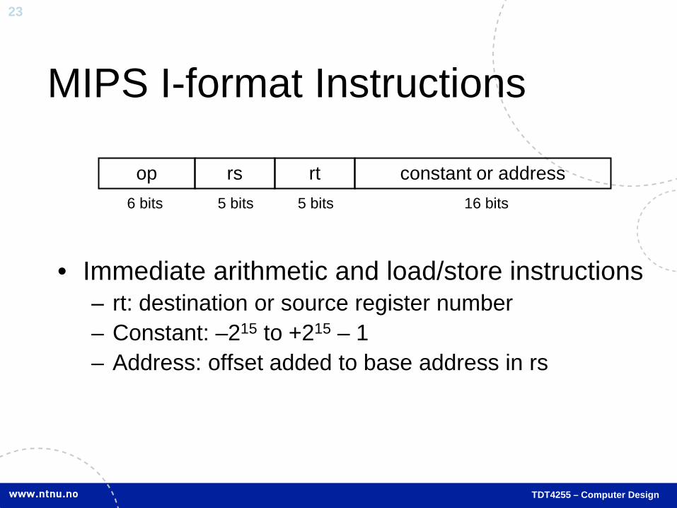
MIPS I-format Instructions
• Immediate arithmetic and load/store instructions – rt: destination or source register number – Constant: –215 to +215 – 1 – Address: offset added to base address in rs
op rs rt constant or address 6 bits 5 bits 5 bits 16 bits
24
TDT4255 – Computer Design
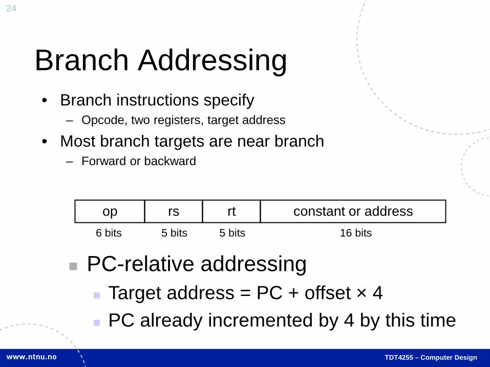
Branch Addressing • Branch instructions specify
– Opcode, two registers, target address
• Most branch targets are near branch – Forward or backward
op rs rt constant or address 6 bits 5 bits 5 bits 16 bits
PC-relative addressing Target address = PC + offset × 4 PC already incremented by 4 by this time

25
TDT4255 – Computer Design
Jump Addressing • Jump (j and jal) targets could be anywhere in text
segment – Encode full address in instruction
op address 6 bits 26 bits
(Pseudo)Direct jump addressing Target address = PC31…28 : (address × 4)

26
TDT4255 – Computer Design
Local Data on the Stack
• Local data allocated by callee – e.g., C automatic variables
• Procedure frame (activation record) – Used by some compilers to manage stack storage

27
TDT4255 – Computer Design
Memory Layout • Text: program code • Static data: global
variables – e.g., static variables in C,
constant arrays and strings – $gp initialized to address
allowing ±offsets into this segment
• Dynamic data: heap – E.g., malloc in C, new in
Java • Stack: automatic storage

28
TDT4255 – Computer Design
Translation and Startup
Many compilers produce object modules directly
Static linking

29
TDT4255 – Computer Design
Chapter 3 Review
Acknowledgement: Slides are adapted from Morgan Kaufmann companion material
30
TDT4255 – Computer Design
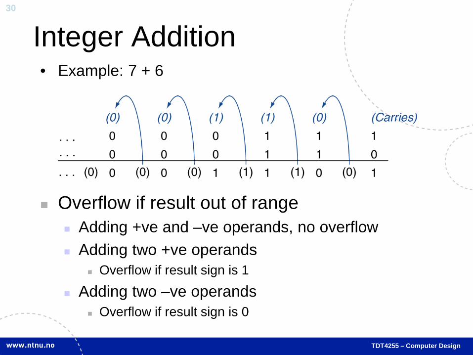
Integer Addition • Example: 7 + 6
Overflow if result out of range Adding +ve and –ve operands, no overflow Adding two +ve operands
Overflow if result sign is 1
Adding two –ve operands Overflow if result sign is 0

31
TDT4255 – Computer Design
Multiplication • Start with long-multiplication approach
1000 × 1001 1000 0000 0000 1000 1001000
Length of product is the sum of operand lengths
multiplicand
multiplier
product

32
TDT4255 – Computer Design
Optimized Multiplier • Perform steps in parallel: add/shift
One cycle per partial-product addition That’s ok, if frequency of multiplications is low

33
TDT4255 – Computer Design
Division • Check for 0 divisor • Long division approach
– If divisor ≤ dividend bits • 1 bit in quotient, subtract
– Otherwise • 0 bit in quotient, bring down next
dividend bit
• Restoring division – Do the subtract, and if remainder
goes < 0, add divisor back • Signed division
– Divide using absolute values – Adjust sign of quotient and remainder
as required
1001 1000 1001010 -1000 10 101 1010 -1000 10
n-bit operands yield n-bit quotient and remainder
quotient
dividend
remainder
divisor
Dividend/Divisor = Quotient

34
TDT4255 – Computer Design
Representable Floating Point Numbers

35
TDT4255 – Computer Design
IEEE Floating-Point Format
• S: sign bit (0 ⇒ non-negative, 1 ⇒ negative) • Normalize significand: 1.0 ≤ |significand| < 2.0
– Always has a leading pre-binary-point 1 bit, so no need to represent it explicitly (hidden bit)
– Significand is Fraction with the “1.” restored • Exponent: excess representation: actual exponent + Bias
– Ensures exponent is unsigned – Single: Bias = 127; Double: Bias = 1203
S Exponent Fraction
single: 8 bits double: 11 bits
single: 23 bits double: 52 bits
Bias)(ExponentS 2Fraction)(11)(x −×+×−=

36
TDT4255 – Computer Design
Chapter 4 Review
Acknowledgement: Slides are adapted from Morgan Kaufmann companion material

37
TDT4255 – Computer Design
Single Cycle Datapath
38
TDT4255 – Computer Design
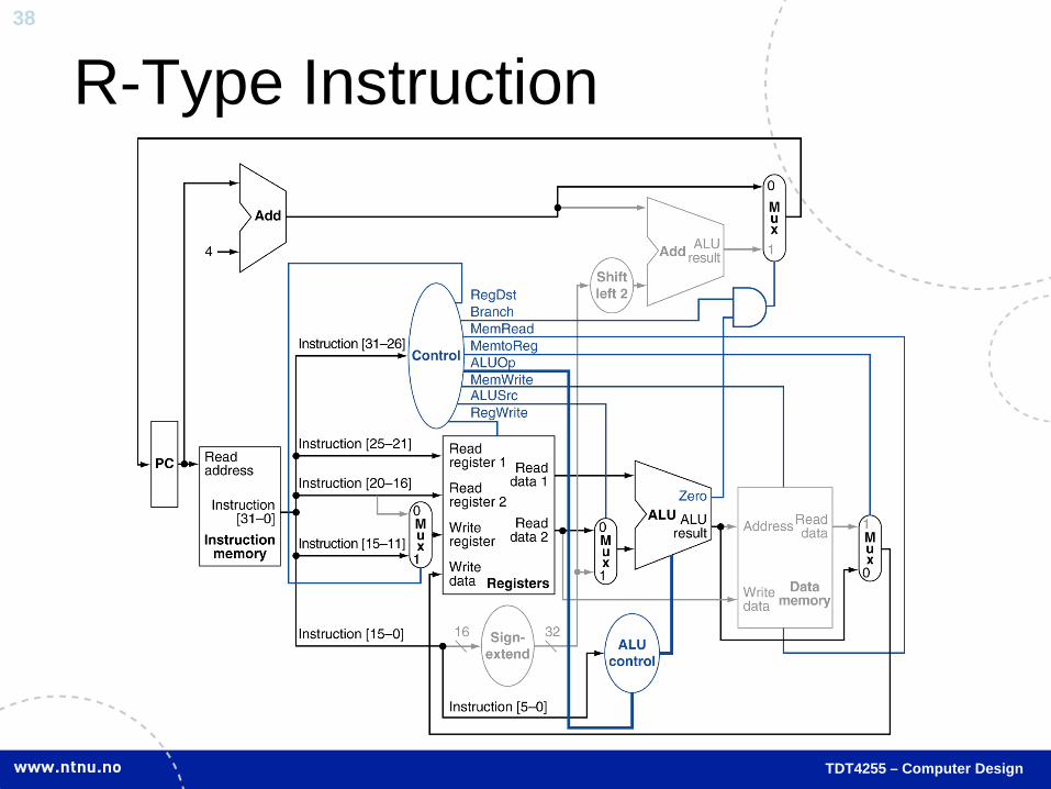
R-Type Instruction
39
TDT4255 – Computer Design
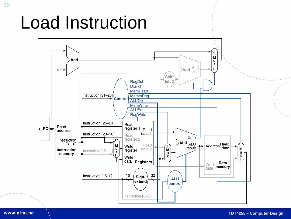
Load Instruction

40
TDT4255 – Computer Design
Branch-on-Equal Instruction
41
TDT4255 – Computer Design
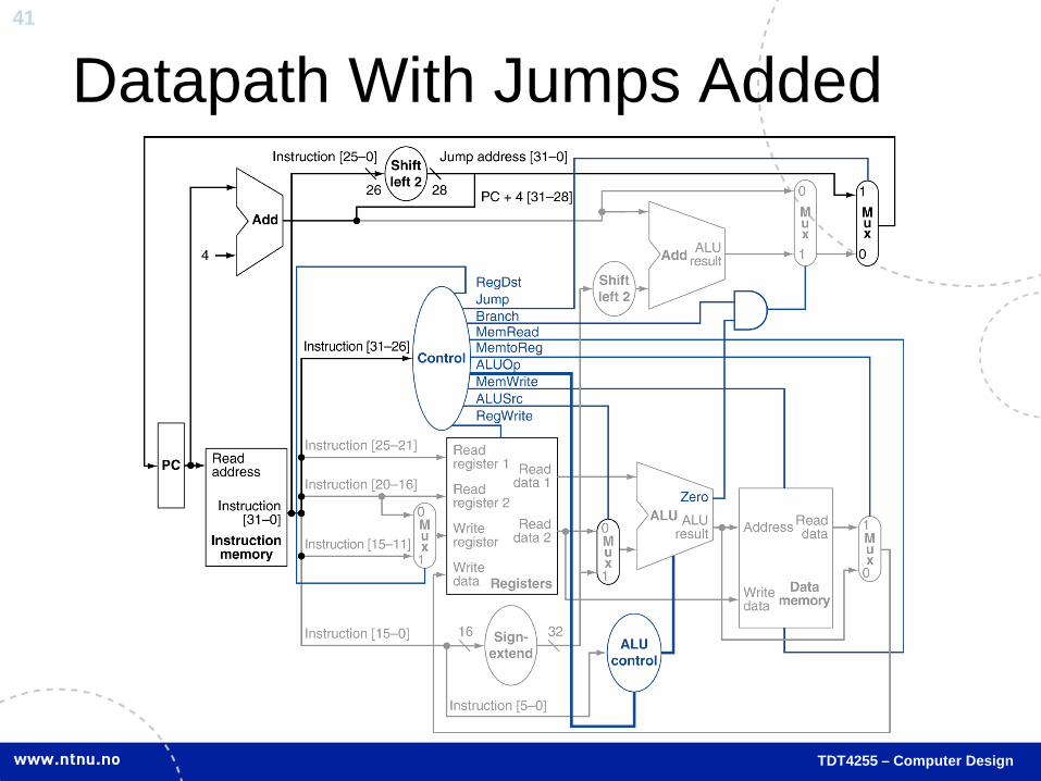
Datapath With Jumps Added

42
TDT4255 – Computer Design
Multi-cycle Datapath (1/2) • Idea: Add registers at strategic points in the datapath • Activate only needed functional units with control
signals
43
TDT4255 – Computer Design
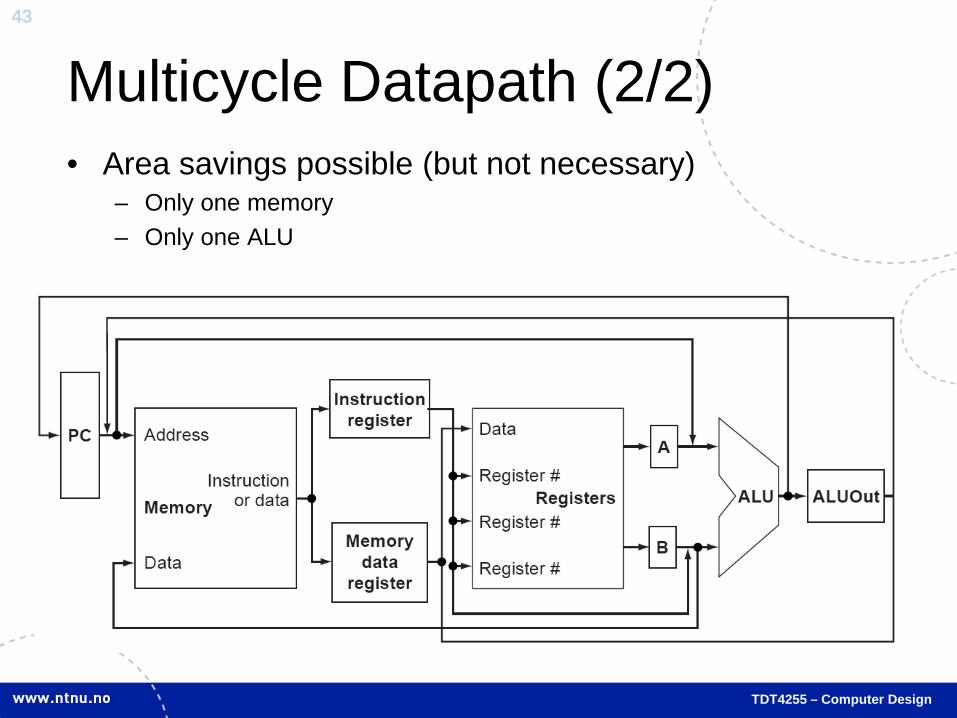
Multicycle Datapath (2/2) • Area savings possible (but not necessary)
– Only one memory – Only one ALU

Chapter 4 Review
Pipeline Hazards
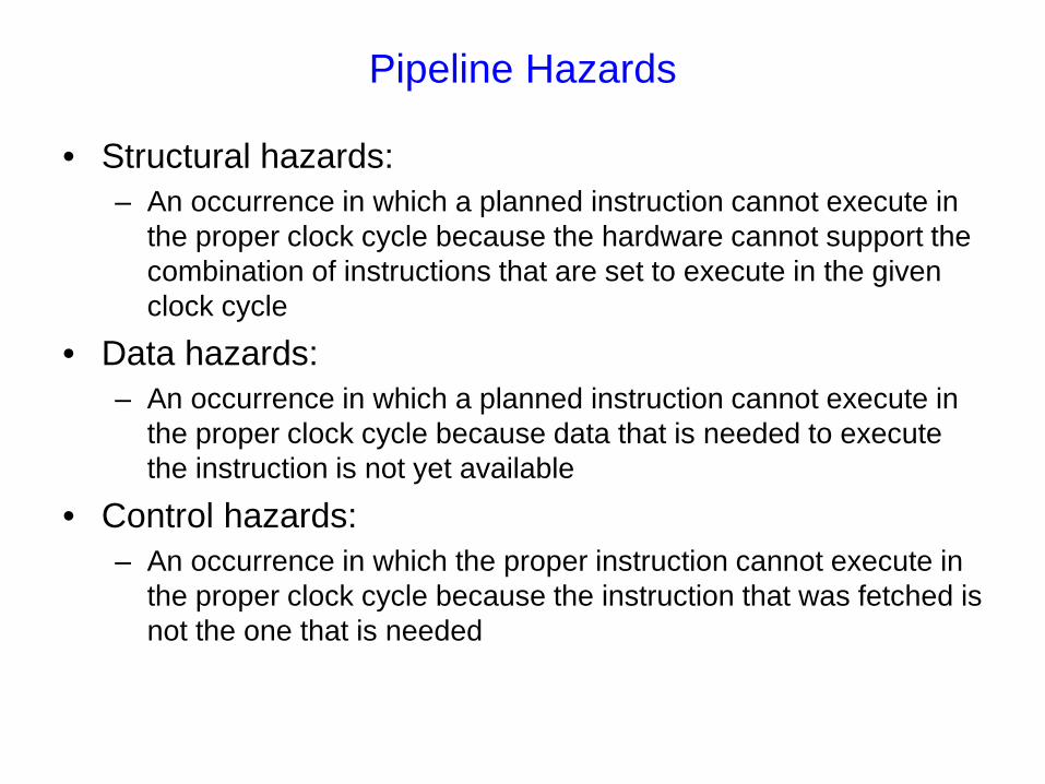
• Structural hazards: – An occurrence in which a planned instruction cannot execute in
the proper clock cycle because the hardware cannot support the combination of instructions that are set to execute in the given clock cycle
• Data hazards: – An occurrence in which a planned instruction cannot execute in
the proper clock cycle because data that is needed to execute the instruction is not yet available
• Control hazards: – An occurrence in which the proper instruction cannot execute in
the proper clock cycle because the instruction that was fetched is not the one that is needed

Structural hazards
• For the pipelined instructions below we would have a structural hazard in clock cycle (cc) 5 if we only had one memory. The second lw is reading from the memory while the 5th lw instruction is being fetched.
• MIPS instruction set is designed to avoid structural hazards
IF ID EX MEM WB
IF ID EX MEM WB
IF ID EX MEM WB
IF ID EX MEM WB
IF ID EX MEM WB
lw
lw
lw
lw
lw
1 2 3 4 5 6 7 8 9
What about the register file????
IF ID EX MEM WB
IF ID EX MEM WB
add $s0, $t0, $t1
sub $t2, $s0, $t3
1 2 3 4 5 6Data Hazards
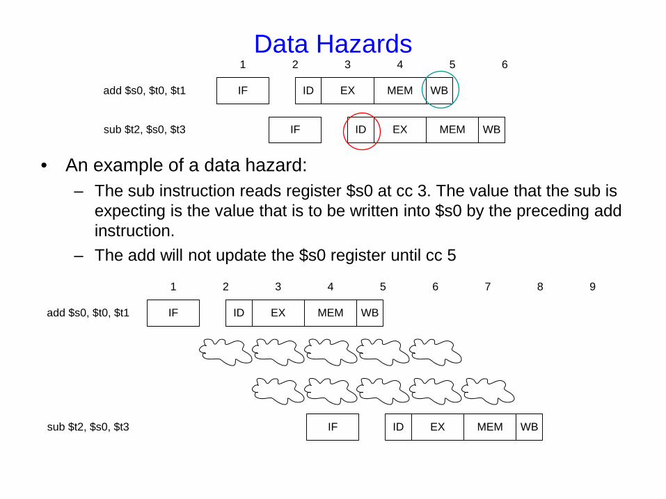
• An example of a data hazard: – The sub instruction reads register $s0 at cc 3. The value that the sub is
expecting is the value that is to be written into $s0 by the preceding add instruction.
– The add will not update the $s0 register until cc 5
IF ID EX MEM WBadd $s0, $t0, $t1
IF ID EX MEM WBsub $t2, $s0, $t3
1 2 3 4 5 6 7 8 9

Data Hazards and forwarding
• The figure above shows that the new value for $s0 is already calculated the clock cycle before it is need by the sub instruction. Making this value available to the sub instruction is called forwarding.
• Forwarding: A method of resolving a data hazard by retrieving the missing data elements from internal buffers rather than waiting for it to arrive from programmer-visible registers or memory
Data Hazards and stalls
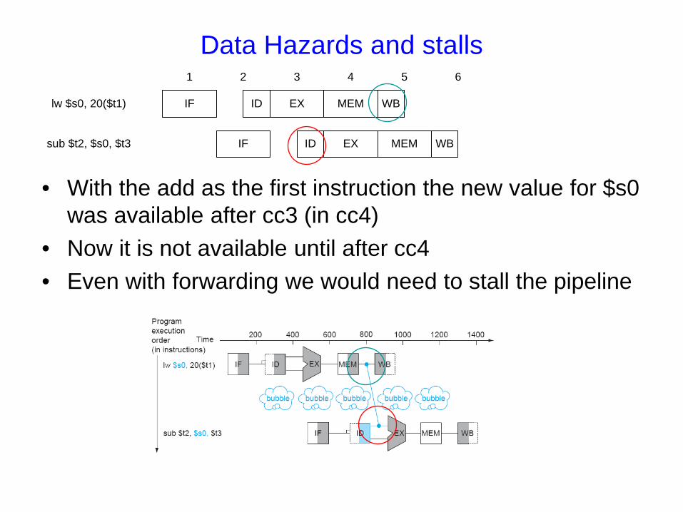
• With the add as the first instruction the new value for $s0 was available after cc3 (in cc4)
• Now it is not available until after cc4 • Even with forwarding we would need to stall the pipeline
IF ID EX MEM WB
IF ID EX MEM WB
lw $s0, 20($t1)
sub $t2, $s0, $t3
1 2 3 4 5 6
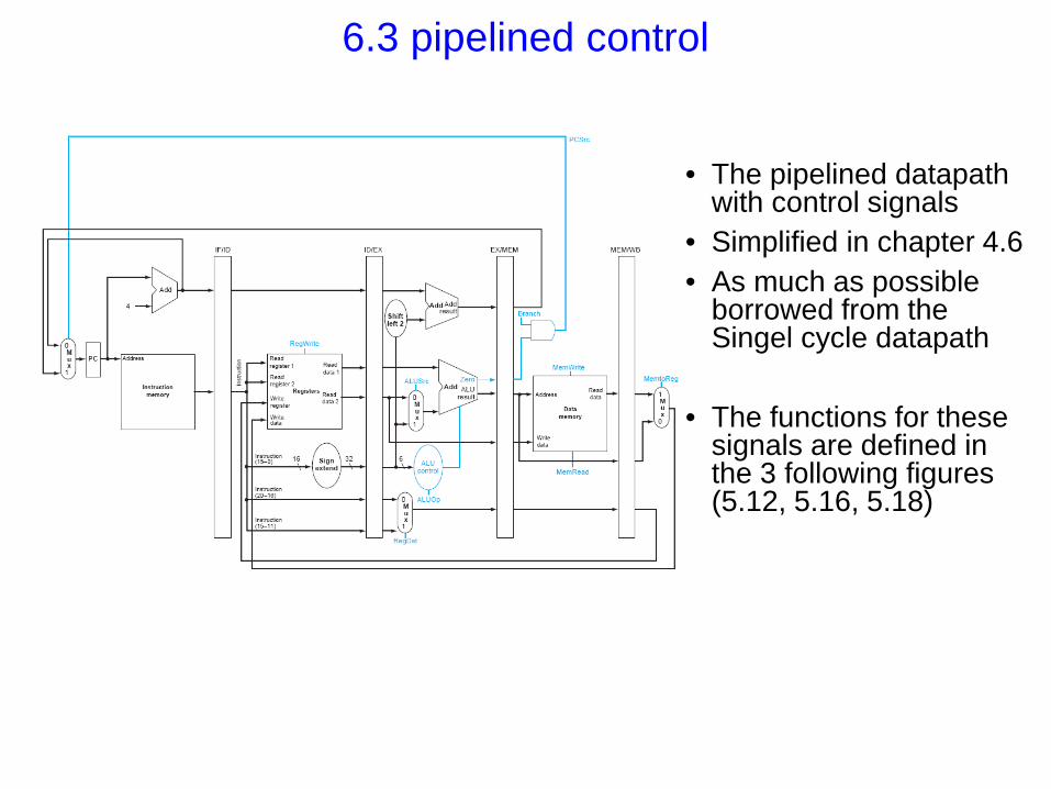
6.3 pipelined control
• The pipelined datapath
with control signals • Simplified in chapter 4.6 • As much as possible
borrowed from the Singel cycle datapath
• The functions for these
signals are defined in the 3 following figures (5.12, 5.16, 5.18)

Chapter 2 HP07 Review

Introduction
Pipelining became a universal technique in 1985 Overlaps execution of instructions Exploits Instruction Level Parallelism (ILP)
Beyond this, there are two main approaches: Hardware-based dynamic approaches
Used in server and desktop processors Compiler-based static approaches
Scientific and embedded markets
Introduction
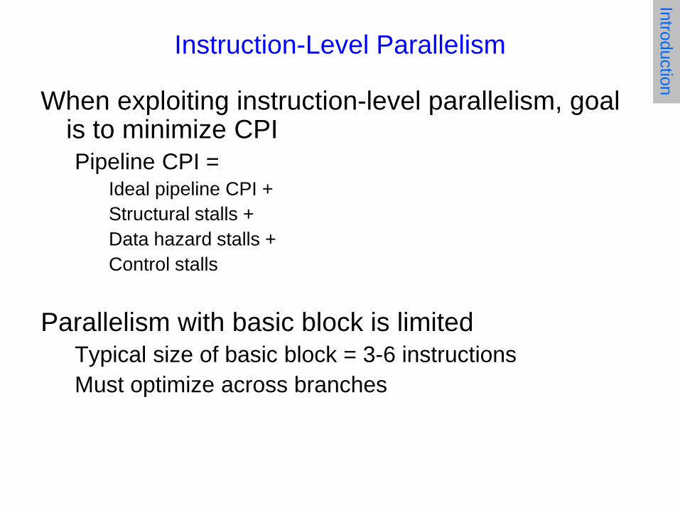
Instruction-Level Parallelism
When exploiting instruction-level parallelism, goal is to minimize CPI Pipeline CPI =
Ideal pipeline CPI + Structural stalls + Data hazard stalls + Control stalls
Parallelism with basic block is limited Typical size of basic block = 3-6 instructions Must optimize across branches
Introduction
Data Dependence
Why can’t we just execute all instructions in parallel?
Challenges: Data dependency (true dependence)
Instruction j is data dependent on instruction i if Instruction i produces a result that may be used by instruction j Instruction j is data dependent on instruction k and instruction k is
data dependent on instruction i This includes registers AND memory! Examples?
Dependent instructions cannot be executed simultaneously
Introduction
Data Dependence
Dependencies are a property of programs (the amount of parallelism is HIGHLY dependent on the type of program)
Pipeline MUST satisfy dependences Data dependences specify:
Order in which instructions MUST be executed. Upper bound on amount of parallelism Data dependencies that flow through memory locations are difficult to detect (example) ?
Introduction
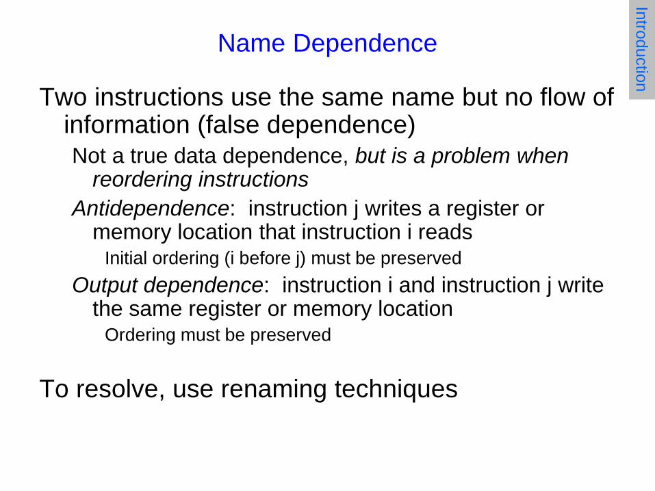
Name Dependence
Two instructions use the same name but no flow of information (false dependence) Not a true data dependence, but is a problem when
reordering instructions Antidependence: instruction j writes a register or
memory location that instruction i reads Initial ordering (i before j) must be preserved
Output dependence: instruction i and instruction j write the same register or memory location
Ordering must be preserved
To resolve, use renaming techniques
Introduction
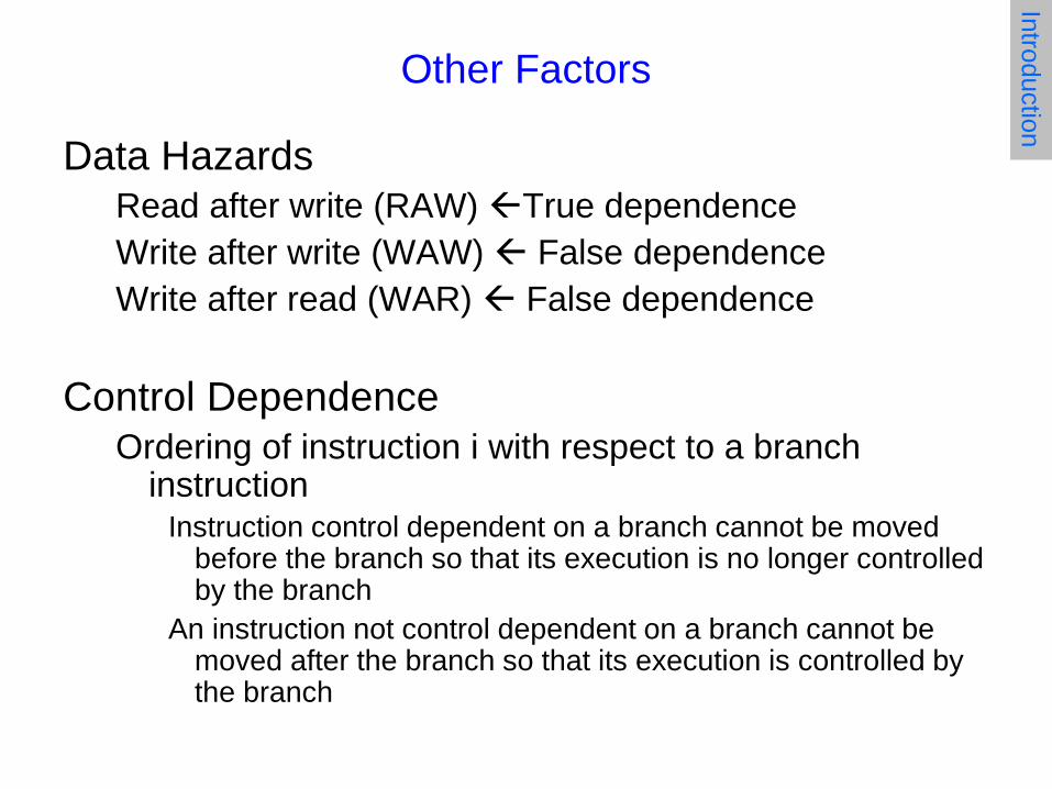
Other Factors
Data Hazards Read after write (RAW) True dependence Write after write (WAW) False dependence Write after read (WAR) False dependence
Control Dependence Ordering of instruction i with respect to a branch
instruction Instruction control dependent on a branch cannot be moved
before the branch so that its execution is no longer controlled by the branch
An instruction not control dependent on a branch cannot be moved after the branch so that its execution is controlled by the branch
Introduction
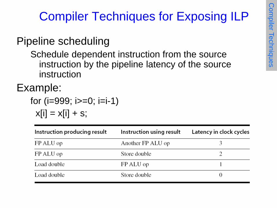
Compiler Techniques for Exposing ILP
Pipeline scheduling Schedule dependent instruction from the source
instruction by the pipeline latency of the source instruction
Example: for (i=999; i>=0; i=i-1) x[i] = x[i] + s;
Com
piler Techniques

Pipeline Stalls
Loop: L.D F0,0(R1) stall ADD.D F4,F0,F2 stall stall S.D F4,0(R1) DADDUI R1,R1,#-8 stall BNE R1,R2,Loop
Com
piler Techniques

Pipeline Scheduling
Scheduled code: Loop: L.D F0,0(R1) DADDUI R1,R1,#-8 ADD.D F4,F0,F2 stall stall S.D F4,8(R1) BNE R1,R2,Loop
Com
piler Techniques
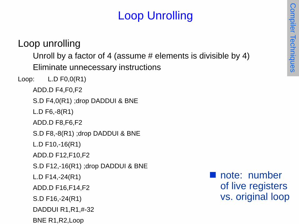
Loop unrolling Unroll by a factor of 4 (assume # elements is divisible by 4) Eliminate unnecessary instructions
Loop: L.D F0,0(R1) ADD.D F4,F0,F2 S.D F4,0(R1) ;drop DADDUI & BNE L.D F6,-8(R1) ADD.D F8,F6,F2 S.D F8,-8(R1) ;drop DADDUI & BNE L.D F10,-16(R1) ADD.D F12,F10,F2 S.D F12,-16(R1) ;drop DADDUI & BNE L.D F14,-24(R1) ADD.D F16,F14,F2 S.D F16,-24(R1) DADDUI R1,R1,#-32 BNE R1,R2,Loop
Loop Unrolling C
ompiler Techniques
note: number of live registers vs. original loop

Loop Unrolling/Pipeline Scheduling
Pipeline schedule the unrolled loop: Loop: L.D F0,0(R1) L.D F6,-8(R1) L.D F10,-16(R1) L.D F14,-24(R1) ADD.D F4,F0,F2 ADD.D F8,F6,F2 ADD.D F12,F10,F2 ADD.D F16,F14,F2 S.D F4,0(R1) S.D F8,-8(R1) DADDUI R1,R1,#-32 S.D F12,16(R1) S.D F16,8(R1) BNE R1,R2,Loop
Com
piler Techniques

Dynamic Scheduling
Rearrange order of instructions to reduce stalls while maintaining data flow
Advantages:
Compiler doesn’t need to have knowledge of microarchitecture
Handles cases where dependencies are unknown at compile time
Disadvantage:
Substantial increase in hardware complexity Complicates exceptions
Branch P
rediction
Dynamic Scheduling
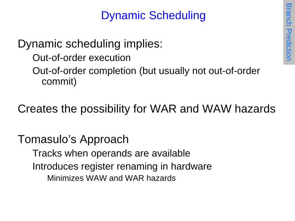
Dynamic scheduling implies: Out-of-order execution Out-of-order completion (but usually not out-of-order
commit)
Creates the possibility for WAR and WAW hazards Tomasulo’s Approach
Tracks when operands are available Introduces register renaming in hardware
Minimizes WAW and WAR hazards
Branch P
rediction

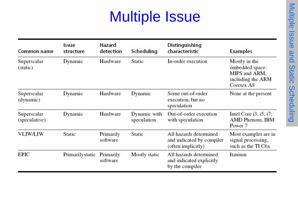
• CPI ≥ 1 if issue only 1 instruction every clock cycle • Multiple-issue processors come in 3 flavors: 1. Statically-scheduled superscalar processors
• In-order execution • Varying number of instructions issued (compiler)
2. Dynamically-scheduled superscalar processors • Out-of-order execution • Varying number of instructions issued (CPU)
3. VLIW (very long instruction word) processors • In-order execution • Fixed number of instructions issued
Getting CPI below 1
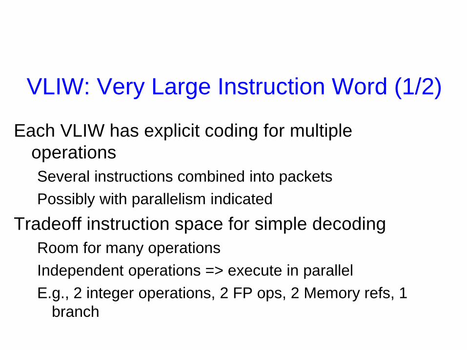
VLIW: Very Large Instruction Word (1/2)
Each VLIW has explicit coding for multiple operations Several instructions combined into packets Possibly with parallelism indicated
Tradeoff instruction space for simple decoding Room for many operations Independent operations => execute in parallel E.g., 2 integer operations, 2 FP ops, 2 Memory refs, 1
branch
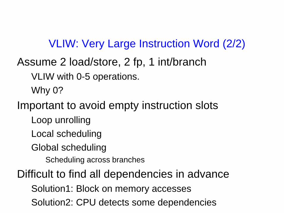
VLIW: Very Large Instruction Word (2/2) Assume 2 load/store, 2 fp, 1 int/branch
VLIW with 0-5 operations. Why 0?
Important to avoid empty instruction slots Loop unrolling Local scheduling Global scheduling
Scheduling across branches
Difficult to find all dependencies in advance Solution1: Block on memory accesses Solution2: CPU detects some dependencies
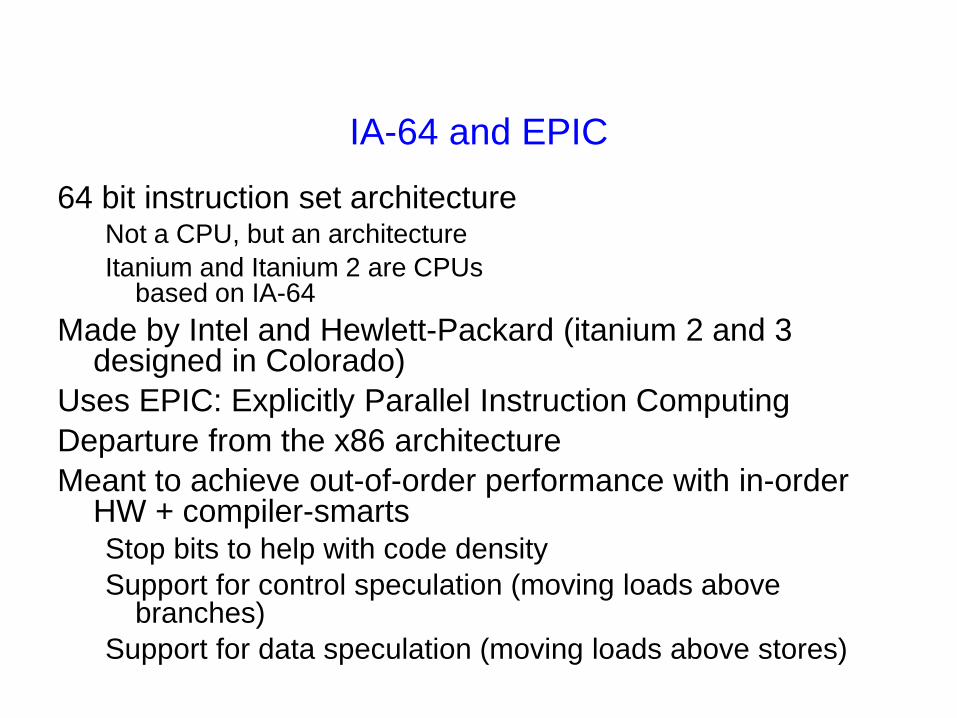
IA-64 and EPIC
64 bit instruction set architecture Not a CPU, but an architecture Itanium and Itanium 2 are CPUs
based on IA-64 Made by Intel and Hewlett-Packard (itanium 2 and 3
designed in Colorado) Uses EPIC: Explicitly Parallel Instruction Computing Departure from the x86 architecture Meant to achieve out-of-order performance with in-order
HW + compiler-smarts Stop bits to help with code density Support for control speculation (moving loads above
branches) Support for data speculation (moving loads above stores)

EPIC Conclusions
Goal of EPIC was to maintain advantages of VLIW, but achieve performance of out-of-order.
Results: Complicated bundling rules saves some space, but
makes the hardware more complicated Add special hardware and instructions for scheduling
loads above stores and branches (new complicated hardware)
Add special hardware to remove branch penalties (predication)
End result is a machine as complicated as an out-of-order, but now also requiring a super-sophisticated compiler.
Multiple Issue M
ultiple Issue and Static S
cheduling
Arvind & Emer October 19, 2011 http://www.csg.csail.mit.edu/6.823
L11-72
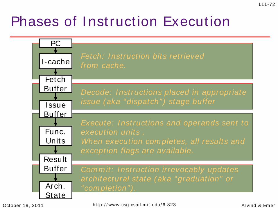
Fetch: Instruction bits retrieved from cache.
Phases of Instruction Execution
I-cache
Fetch Buffer
Issue Buffer
Func. Units
Arch. State
Execute: Instructions and operands sent to execution units . When execution completes, all results and exception flags are available.
Decode: Instructions placed in appropriate issue (aka “dispatch”) stage buffer
Result Buffer Commit: Instruction irrevocably updates
architectural state (aka “graduation” or “completion”).
PC

Arvind & Emer October 19, 2011 http://www.csg.csail.mit.edu/6.823
L11-73
Dataflow execution
Instruction slot is candidate for execution when: •It holds a valid instruction (“use” bit is set) •It has not already started execution (“exec” bit is clear) •Both operands are available (p1 and p2 are set)
Reorder buffer
t1 t2 . . . tn
ptr2 next to
deallocate
prt1 next
available
Ins# use exec op p1 src1 p2 src2
Arvind & Emer October 19, 2011 http://www.csg.csail.mit.edu/6.823
L11-74
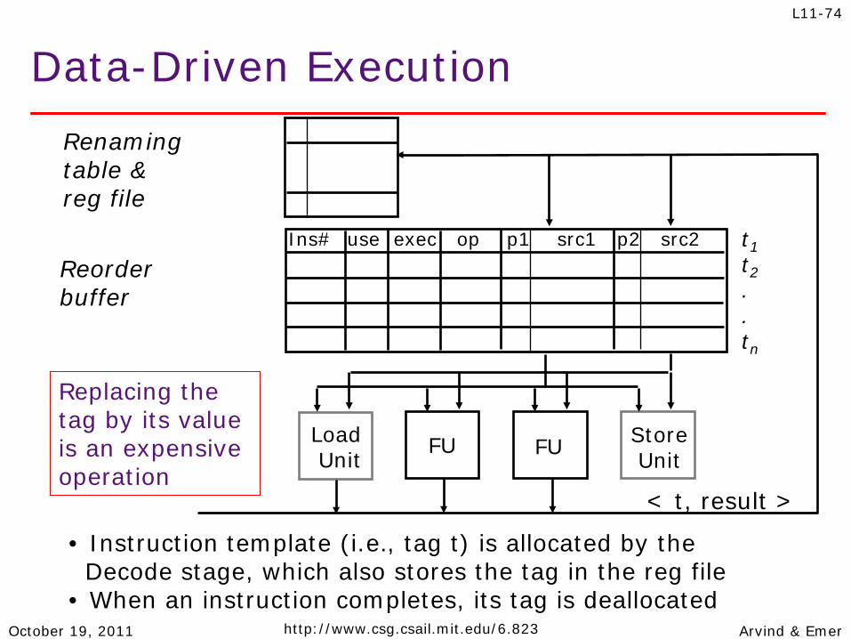
Data-Driven Execution Renaming table & reg file
Reorder buffer
Load Unit
FU FU Store Unit
< t, result >
Ins# use exec op p1 src1 p2 src2 t1 t2 . . tn
• Instruction template (i.e., tag t) is allocated by the Decode stage, which also stores the tag in the reg file • When an instruction completes, its tag is deallocated
Replacing the tag by its value is an expensive operation

Arvind & Emer October 26, 2011 http://www.csg.csail.mit.edu/6.823
L13-75
Basic Operation: • Enter op and tag or data (if known) for each source • Replace tag with data as it becomes available • Issue instruction when all sources are available • Save dest data when operation finishes • Commit saved dest data when instruction commits
O-o-O Execution with ROB Register
File
Reorder buffer
LoadUnit FU FU FU Store
Unit
< t, result >
Ins# use exec op p1 src1 p2 src2 pd dest data
Commit
Rename Table
R1 titj
0R2
tagvalid bit
t1t2..tn
0 X X add X 1 X 2 X R4 4
8 X ld X 256 R3
R1 1R2 2R3 3
:
Next to commit
Next available
: :
R3R4
t2
t1
011
Register File
Reorder buffer
LoadUnit FU FU FU Store
Unit
< t, result >
Ins# use exec op p1 src1 p2 src2 pd dest dataIns# use exec op p1 src1 p2 src2 pd dest data
Commit
Rename Table
R1 titj
0R2
tagvalid bit
t1t2..tn
0 X X add X 1 X 2 X R4 4
8 X ld X 256 R3
R1 1R2 2R3 3
:
Next to commit
Next available
: :
R3R4
t2
t1
011
Arvind & Emer October 26, 2011 http://www.csg.csail.mit.edu/6.823
L13-76
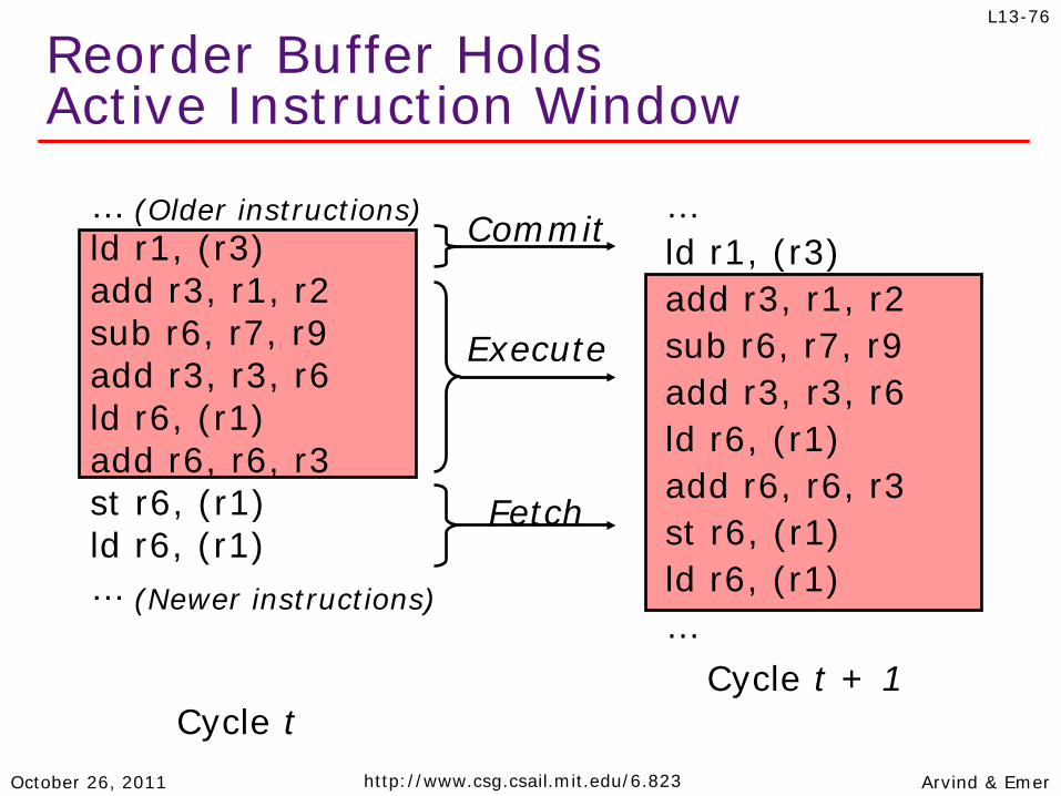
Reorder Buffer Holds Active Instruction Window
… ld r1, (r3) add r3, r1, r2 sub r6, r7, r9 add r3, r3, r6 ld r6, (r1) add r6, r6, r3 st r6, (r1) ld r6, (r1) …
(Older instructions)
(Newer instructions)
Cycle t
… ld r1, (r3) add r3, r1, r2 sub r6, r7, r9 add r3, r3, r6 ld r6, (r1) add r6, r6, r3 st r6, (r1) ld r6, (r1) …
Commit
Fetch
Cycle t + 1
Execute
Arvind & Emer October 26, 2011 http://www.csg.csail.mit.edu/6.823
L13-77
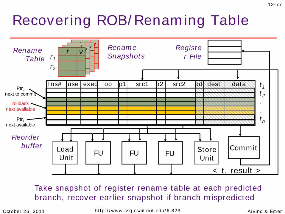
Recovering ROB/Renaming Table
Register File
Reorder buffer Load
Unit FU FU FU Store Unit
< t, result >
t1 t2 . . tn
Ins# use exec op p1 src1 p2 src2 pd dest data
Commit
Rename Table r1
r2
Take snapshot of register rename table at each predicted branch, recover earlier snapshot if branch mispredicted
t v t v t v Rename Snapshots
Ptr2 next to commit
Ptr1 next available
rollback next available
t v
Arvind & Emer October 26, 2011 http://www.csg.csail.mit.edu/6.823
L13-78
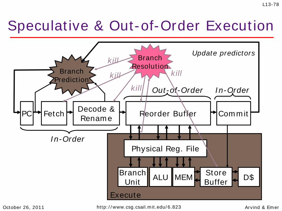
Speculative & Out-of-Order Execution
Fetch Decode & Rename Reorder Buffer PC
Branch Prediction
Update predictors
Commit
Branch Resolution
Branch Unit ALU MEM Store
Buffer D$
Execute
In-Order
In-Order Out-of-Order
Physical Reg. File
kill
kill kill
kill
Arvind & Emer October 19, 2011 http://www.csg.csail.mit.edu/6.823
L11-79
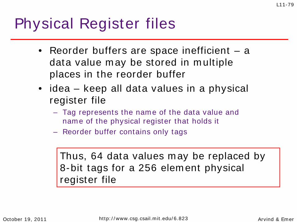
Physical Register files
• Reorder buffers are space inefficient – a data value may be stored in multiple places in the reorder buffer
• idea – keep all data values in a physical register file – Tag represents the name of the data value and
name of the physical register that holds it – Reorder buffer contains only tags
Thus, 64 data values may be replaced by 8-bit tags for a 256 element physical register file

Chapter 5 Review
Principle of Temporal Locality
If you read an address once, you are likely to touch it again. (variables)
If you execute an instruction once, you are likely to execute it again (loops).
Temporal locality Addresses recently referenced will tend to be
referenced again soon Caches exploit temporal locality!

Principle of Spatial locality
If you read an address once, you are likely to also read neighbouring addresses (arrays)
If you execute an instruction once, you are likely to access neighbouring instructions.
Spatial locality If you access address X, you are likely to access an
address close to X. Caches exploit spatial locality!
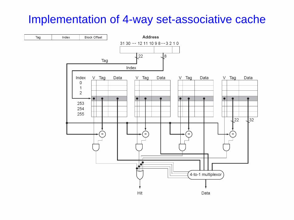
Implementation of 4-way set-associative cache


![VARIO Magnus [e]Magnus](https://static.fdocuments.us/doc/165x107/62e7b22695cddb648811f746/vario-magnus-emagnus.jpg)