TDS MHLSW THFKQLFD Datasheet - Delta Mobrey
17
TDS-MHLSW-A: APRIL 2021 www.delta-mobrey.com Page 1 of 17 Technical Datasheet Magnetic Horizontal Level Switches Weatherproof Aluminium-bronze and Stainless Steel Wetside models Key Features • Operates in almost every liquid, even at high pressure or temperature • Tough, rugged design for long life in aggressive environ- ments • Magnetically coupled • No glands or linkages that could cause leaks Product applications • • • Pump control duty • Interface duty • Dirty Liquids Series Overview The Mobrey magnetic horizontal float switch is ideal for high and low liquid level alarm, and pump control duties. It is designed to open or close a circuit as a changing liquid level within a vessel passes the level of the float. When the process liquid level is below the switch point, contacts B- B are made and contacts A-A are open, but if the liquid level is above the switch point, contacts A-A are made and contacts B-B are open. This proven design with over 100 year of experience, allows for fit and forget of the instrument. How can we help you? Delta Mobrey offers fast, efficient and knowledgeable support when and where you need it. Please visit our web site at www.delta-mobrey.com to find your local support centre or call us on: +44 (0)1252 729140 Magnetic Horizontal Level Switches Model: Aluminium-bronze & Stainless steel Other products Other products we can offer : • Vertical level switches • 003 Gap Sensor
Transcript of TDS MHLSW THFKQLFD Datasheet - Delta Mobrey

TDS-MHLSW-A: APRIL 2021
www.delta-mobrey.com
Page 1 of 17
Technical Datasheet
Magnetic Horizontal Level Switches
Weatherproof Aluminium-bronze and Stainless Steel Wetside models
Key Features
• Operates in almost every liquid, even at high pressure or temperature
• Tough, rugged design for long life in aggressive environ-ments
• Magnetically coupled
• No glands or linkages that could cause leaks
Product applications
•
•
• Pump control duty
• Interface duty
• Dirty Liquids
Series Overview
The Mobrey magnetic horizontal float switch is ideal for high and
low liquid level alarm, and pump control duties. It is designed to
open or close a circuit as a changing liquid level within a vessel
passes the level of the float.
When the process liquid level is below the switch point, contacts B-
B are made and contacts A-A are open, but if the liquid level is
above the switch point, contacts A-A are made and contacts B-B
are open.
This proven design with over 100 year of experience, allows for fit and forget of the instrument.
How can we help you?
Delta Mobrey offers fast, efficient and
knowledgeable support when and where
you need it. Please visit our web site at
www.delta-mobrey.com to find your
local support centre or call us on:
+44 (0)1252 729140
Magnetic Horizontal Level Switches
Model: Aluminium
-bronze & Stainless steel
Other products
Other products we can offer :
• Vertical level switches • 003 Gap Sensor

TDS-MHLSW-A: APRIL 2021
www.delta-mobrey.com
Page 2 of 17
How to order
Instrument can be configured by selecting codes representing the desired features from the tables that follow.
The chart below, describes how the model code is built up. For assistance in configuring a switch that best suits your needs, please contact your local sales office.
Base Model Table 1
Flange (head) Table 2
Switch Mechanism Table 3
Magnetic Horizontal Level Switches
Model: Aluminium
-bronze & Stainless steel
S /
Enclosure Table 4
Float Table 5

TDS-MHLSW-A: APRIL 2021
www.delta-mobrey.com
Page 3 of 17
Models TABLE 1
Description Code
Horizontal float switch S
Magnetic Horizontal Level Switches
Model: Aluminium
-bronze & Stainless steel
Flange (head) (1)
S /
TABLE 2
Description Max T
process (2) Code
General purpose, aluminium bronze wetside, Mobrey 'A' flange, 261 psi (18 bar) 410 °F (210 °C) 01
General purpose, stainless steel wetside, Mobrey 'A' flange, 490 psi (33.8 bar) 752 °F (400 °C) 36 (3), (4)
General purpose, stainless steel wetside, Mobrey 'A' flange, 490 psi (33.8 bar) 356 °F (180 °C) 190 (3), (4), (5)
General purpose, stainless steel wetside, 3 in. ASME B16.5 Class 150 RF flange 752 °F (400 °C) 440
General purpose, stainless steel wetside, 4 in. ASME B16.5 Class 150 RF flange 752 °F (400 °C) 441
General purpose, stainless steel wetside, 3 in. ASME B16.5 Class 300 RF flange 752 °F (400 °C) 424
General purpose, stainless steel wetside, 4 in. ASME B16.5 Class 300 RF flange 752 °F (400 °C) 425
General purpose, stainless steel wetside, 3 in. ASME B16.5 Class 600 RF flange 752 °F (400 °C) 489
General purpose, stainless steel wetside, 3 in. ASME B16.5 Class 900 RF flange 752 °F (400 °C) 490
General purpose, stainless steel wetside, EN 1092-1 DN 65 PN 16 (4 bolt hole) flange 752 °F (400 °C) 428
General purpose, stainless steel wetside, EN 1092-1 DN 80 PN 16 flange 752 °F (400 °C) 429
General purpose, stainless steel wetside, EN 1092-1 DN 100 PN 16 flange 752 °F (400 °C) 430
General purpose, stainless steel wetside, EN 1092-1 DN 125 PN 16 flange 752 °F (400 °C) 431
General purpose, stainless steel wetside, EN 1092-1 DN 150 PN 16 flange 752 °F (400 °C) 432
General purpose, stainless steel wetside, EN 1092-1 DN 65 PN 40 flange 752 °F (400 °C) 417
General purpose, stainless steel wetside, EN 1092-1 DN 80 PN 40 flange 752 °F (400 °C) 418
General purpose, stainless steel wetside, EN 1092-1 DN 100 PN 40 flange 752 °F (400 °C) 419
General purpose, stainless steel wetside, EN 1092-1 DN 125 PN 40 flange 752 °F (400 °C) 433
General purpose, stainless steel wetside, EN 1092-1 DN 150 PN 40 flange 752 °F (400 °C) 434
General purpose, stainless steel wetside, EN 1092-1 DN 80 PN 63 flange 752 °F (400 °C) 488
General purpose, stainless steel wetside, EN 1092-1 DN 100 PN 63 flange 752 °F (400 °C) 435
General purpose, stainless steel wetside, EN 1092-1 DN 125 PN 63 flange 752 °F (400 °C) 436
General purpose, stainless steel wetside, EN 1092-1 DN 150 PN 63 flange 752 °F (400 °C) 437
S /

TDS-MHLSW-A: APRIL 2021
www.delta-mobrey.com
Page 4 of 17
Magnetic Horizontal Level Switches
Model: Aluminium
-bronze & Stainless steel
Switch Mechanism (6)
TABLE 3 S /
Description Code Max T
Process (2)
Electrical: 2 independent Single Pole Single Throw (SPST) contact sets D 752 °F (400 °C)
As type D but with gold plated contacts 752 °F (400 °C) P
Electrical: 2 independent circuits of Double Pole Double Throw (DPDT) contact sets 752 °F (400 °C) D6
As type D6 but with gold plated contacts 752 °F (400 °C) P6
As type D6 but with gold plated contacts and hermetically sealed moving parts 482 °F (250 °C) H6
As type H6 but approved for Zone 2 areas 482 °F (250 °C) B6
Pneumatic: air pilot valve on/off for switching air circuits 752 °F (400 °C) AP
Pneumatic: air pilot valve for continuous modulating of air controlled circuits 752 °F (400 °C) AM(7)
Switch Enclosure TABLE 4 S /
Description Switch Type Code
Aluminium alloy All A
Aluminium bronze (S01 switch head) Not H6, B6, AP or AM B

TDS-MHLSW-A: APRIL 2021
www.delta-mobrey.com
Page 5 of 17
Float (All ratings at T
room) (8) TABLE 5
Description Switch Code
General purpose high/low alarm, 316 SST, min. SG 0.65, 500 psi (34.5 bar) All F84
Horizontal variable differential for pump control/alarm, 316 SST, min. SG 0.72, 500 psi (34.5 bar)
All except
AM F68/1(9)
Horizontal variable differential for pump control/alarm, 316 SST, min. SG 0.85, 500 psi (34.5 bar)
All except
AM F68/4(9)
Vertical pump control or alarm, 316 SST, rod length 1524mm, 435 psi (30 bar) All except
AM F21/1
(9)
Vertical pump control or alarm, 316 SST, rod length 3048mm, 435 psi (30 bar) All except
AM F21/2(9)
Vertical pump control or alarm, 316 SST, rod length 4570mm, 435 psi (30 bar) All except
AM F21/3(9)
Straight aim, 316 SST, rod length 750mm, 500 psi (34.5 bar) All F104/1(9)
Cranked arm, horizontal, 316 SST, dimensions to be specified, 500 psi (34.5 bar) All F104/2(9)
Cranked arm, vertical, 316 SST, dimensions to be specified, 500 psi (34.5 bar) All F104/3(9)
Shrouded for dirty liquids, 316 SST, min. SG 0.75, atmospheric All F93(5),(10)
General purpose high/low alarm, Alloy 400, min. SG 0.65, 500 psi (34.5 bar) All F185
General purpose high/low alarm, 316 SST, min. SG 0.60, 1073 psi (74 bar) All F96
General purpose high/low alarm, 316 SST, min. SG 0.45, 500 psi (34.5 bar) All F98
General purpose high/low alarm, 316 SST, min. SG 0.51, 1073 psi (74 bar) All F106
General purpose high/low alarm, 316 SST, min. SG 0.71, 2900 psi (200 bar) All F107
Interface duties, 3166 SST, min. SG 0.80, 1073 psi (74 bar) All F88
Horizontal limited differential, Alloy 400, min. SG 0.85, 464 psi (32 bar) All except
AM F264
S /
Magnetic Horizontal Level Switches
Model: Aluminium
-bronze & Stainless steel
1. See table 10 for nozzle and stud lengths.
2. The maximum allowed process temperature is dependent on Flange (Head), Switch mechanism, and Float
options chosen.
3. There is no back flange fitted to the S36 and S190 flange (head).
4. See page 9 for Mobrey flange information.
5. The S190 flange (head) can only be used with the F93 float.
6. See “Switch mechanism specifications” on page 8 for information about all switch mechanisms.
7. Switch mechanism type AM is not compatible with float types F68/+, F21/+ or F264.
8. See Table 9 for a comparison of the float options listed here.
9. See pages 13, 14, 15 and 16 for technical float details and length options.
10. A silicone rubber gaiter is supplied with the 316 SST shroud.
TDS-MHLSW-A: APRIL 2021
www.delta-mobrey.com
Page 6 of 17
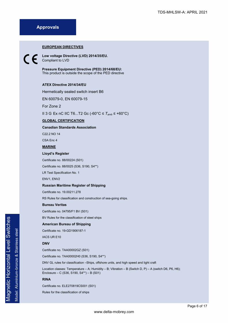
Approvals
EUROPEAN DIRECTIVES
Low voltage Directive (LVD) 2014/35/EU.
Compliant to LVD
Pressure Equipment Directive (PED) 2014/68/EU: This product is outside the scope of the PED directive
Magnetic Horizontal Level Switches
Model: Aluminium
-bronze & Stainless steel
ATEX Directive 2014/34/EU
Hermetically sealed switch insert B6
EN 60079-0, EN 60079-15
For Zone 2
II 3 G Ex nC IIC T6...T2 Gc (-60°C ≤ Tamb ≤ +60°C)
GLOBAL CERTIFICATION
Canadian Standards Association
C22.2 NO 14
CSA Enc 4
MARINE
Lloyd’s Register
Certificate no. 88/00224 (S01)
Certificate no. 88/0025 (S36, S190, S4**)
LR Test Specification No. 1
ENV1, ENV2
Russian Maritime Register of Shipping
Certificate no. 19.00211.278
RS Rules for classification and construction of sea-going ships.
Bureau Veritas
Certificate no. 04795/F1 BV (S01)
BV Rules for the classification of steel ships
American Bureau of Shipping
Certificate no. 19-GD1906187-1
IACS UR E10
DNV
Certificate no. TAA00002GZ (S01)
Certificate no. TAA00002H0 (S36, S190, S4**)
DNV GL rules for classification –Ships, offshore units, and high speed and light craft
Location classes: Temperature – A; Humidity – B; Vibration – B (Switch D, P) – A (switch D6, P6, H6);
Enclosure – C (S36, S190, S4**) – B (S01)
RINA
Certificate no. ELE270819CS001 (S01)
Rules for the classification of ships

TDS-MHLSW-A: APRIL 2021
www.delta-mobrey.com
Page 7 of 17
Magnetic Horizontal Level Switches
Model: Aluminium
-bronze & Stainless steel
Table 6 Float Switch Specification – Aluminium bronze wetside - General Application
Electric models
Enclosure & wetside Aluminium Bronze to BS 1400 – AB1 maximum iron content 2.5%
IP rating Weatherproof to IEC 60529 (IP66)
End Cap Short (4 contacts) e.g. S01DB, Aluminium to BS 1490 – grade LM24
Long (6 contacts) e.g. S01D6B, Brass to BS 1400 – DCB3
Maximum Process Temperature 410°F (210°C) if shrouded float F93 used, maximum 356°F (180°C)
Gasket Material Non-asbestos sheet material gaskets to BS 7531 Grade X, which has upper temperature limits of 482°F (250°C) for Gas, vapor and Steam and 824°F (440°C) for liquids
Dimensions See page 9
Air pilot valve models
Enclosure Aluminium Alloy to BS 1490 Grade LM24
Valve Block Aluminium Alloy to BS 1490 Grade LM24
Finish All external aluminium surfaces are chromate phosphate treated and then externally painted
Maximum Process Temperature 410°F (210°C) if shrouded float F93 used, maximum 356°F (180°C)
Gasket Material Non-asbestos sheet material gaskets to BS 7531 Grade X, which has upper temperature limits of 482°F (250°C) for Gas, vapor and Steam and 824°F (440°C) for liquids
Dimensions See page 9
Table 7 Float Switch Specification – Stainless Steel wetside - General Application
Electric models
Enclosure / Housing material Aluminium Alloy to BS 1490 Grade LM24
IP rating Weatherproof to IEC 60529 (IP66)
Wetside material 316 Stainless Steel (to Mobrey std.)
316S33 Stainless Steel for S489 and S490 switch types
Back Flange
Carbon Steel to BS 1501 : 224 grade 430B LT50
This material has guaranteed properties at high 752°F (400°C) and low -58°F (-50°C ) temperatures
Cable Gland
Nickel-plated brass gland with a fully insulated polychloroprene-nitrile rubber CR/NBR gasket seals. Clamping range from 8 to 13 mm OD cable
Maximum ambient temperature is 176°F (80°C)
Maximum Process Temperature Dependent upon Flange (head), switch mechanism and float option chosen. Note: See gasket materials below for gasket temperature limits
Gasket Material
Float switches with ASME B16.5 class 600, 900 or EN1062-1 PN63 flanges are fitted with spiral non-asbestos filled gaskets rated 752°F (400°C)
Otherwise non-asbestos sheet material gaskets to BS 7531 Grade X, which has upper tem-perature limits of 482°F (250°C) for gas, vapor and Steam and 824°F (440°C) for liquids. For higher gas, vapor or Steam temperatures a suitable gasket must be used
Dimensions See page 10
Air pilot valve models
Enclosure Aluminium Alloy to BS 1490 Grade LM24
Valve Block Aluminium Alloy to BS 1490 Grade LM24
Finish All external aluminium surfaces are chromate phosphate treated and then externally painted
Maximum Process Temperature Dependent upon Flange (head), switch mechanism and float option chosen. Note: See gas-ket materials below for gasket temperature limits.
Connections Brass compression couplings to suit 0.24” (6mm) copper or nylon pipe (coupling ¼“ BSP)
Gasket Material
Float switches with ASME B16.5 class 600, 900 or EN1062-1 PN63 flanges are fitted with spiral non-asbestos filled gaskets rated 752°F (400°C)
Otherwise non-asbestos sheet material gaskets to BS 7531 Grade X, which has upper tem-perature limits of 482°F (250°C) for gas, vapor and Steam and 824°F (440°C) for liquids. For higher gas, vapor or Steam temperatures a suitable gasket must be used
Dimensions See page 10
Switch Characteristics

TDS-MHLSW-A: APRIL 2021
www.delta-mobrey.com
Page 8 of 17
Magnetic Horizontal Level Switches
Model: Aluminium
-bronze & Stainless steel
Electrical switch mechanism specification
Electrical switch specification
D and D6 P and P6 H6 and B6
Contact Material Fine Silver Gold Plated Gold plated
Process Temperature -22 to 752°F (-30 to 400°C) -22 to 752°F (-30 to 400°C) -148 to 482°F (-100 to 250°C)
Ambient Temperature -22 to 158°F (-30 to 70°C) -22 to 158°F (-30 to 70°C) -76 to 158°F (-60 to 70°C)
Insulation Valve (Live to earth) > 100MOhm
Terminals D and P : M4 screws with non-rotating clamp plates
D6 and P6 : 6 way terminal block with pressure plates
Electrical specification AC DC inductive DC resistive
Maximum Voltage V 440 240 240
Maximum Current A 5.0 (1) 1.0 2.0
Maximum Power 2000 VA 35 Watts 70 Watts
Power factor 0.4 maximum Time constant 40ms maximum
1. Maximum Current for “D” is 8A up to 410°F (210°C) WARNING The plating of gold contacts may be permanently damaged when used to switch circuits above the following limits : 300V 12mA resistive – 24V 2mH/200mA inductive – 24V 250mA resistive – 24V 750mH/10mA inductive NOTE: LVD (Low Voltage Directive) applied : EN60947 Parts 1 and 5.1
Table 8 Electrical switch mechanism specification
Electrical type D and P Electrical type D6 and P6 Electrical type H6 and B6 Pneumatic type AP and AM
Electrical switch mechanism Pneumatic switch mechanism
Type D
• For alternative make and break circuits
• Function: 2 independent Single Pole Single Throw contacts sets and “snap-action” May be wired S.P.C.O. on site
Type AP
• For switching air circuits
• Function change-over
• Air pressure (air must be clean and dry): Maximum air pressure through valve : 100 psi (7 bar) Maximum air flow through valve : 66 l/m at 100psi (7bar)
• Nominal leakage rate of 0.2%
• Connections : brass compression couplings to suit 0.24in (6mm) copper or nylon pipe, coupling thread ¼ “ BSP
Type D6
• For switching two independent circuits
• Function Double Pole change over (2 independent circuits) and “snap-action”
Type P and P6
• As type D and D6 but with Gold Plated Contacts for switching low power (e.g. Intrinsically Safe) electrical circuits
Type AM
• For modulating air controlled circuits
• Function continuous modulation
• Air pressure (air must be clean and dry): Maximum air pressure through valve : 20 psi (1.4 bar) Modulation linear 0 to 20 psi (0 to 1.4 bar. 2.9 psi to 20 psi (0.2 to 1.4 Bar) available on request.
• Temperature Medium 34 to 752°F (1 to 400 °C) Ambient 34 to 140 °F (1 to 60 °C) Lower ambient temperature can be tolerated if the air supply is 100% dry
Type H6
• For use in corrosive area and/or low temperature applications
• As type D6 but with Gold Plated Contacts and housed in an Inert Gas filled, Hermetically sealed enclosure
Type B6
• For use in Zone 2 Hazardous Area
• As type H6 but coded ATEX II 3G, EExnC IIC T6 -76°F (-60°C) <Ta<140°F (60°C)
Electric Characteristics
TDS-MHLSW-A: APRIL 2021
www.delta-mobrey.com
Page 9 of 17
Magnetic Horizontal Level Switches
Model: Aluminium
-bronze & Stainless steel
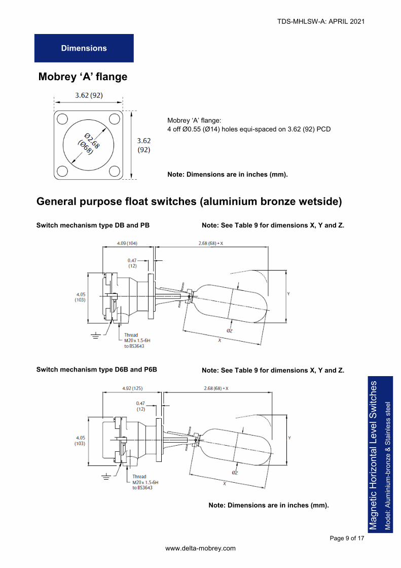
Dimensions
Mobrey ‘A’ flange:
4 off Ø0.55 (Ø14) holes equi-spaced on 3.62 (92) PCD
Note: Dimensions are in inches (mm).
Mobrey ‘A’ flange
Note: Dimensions are in inches (mm).
Note: See Table 9 for dimensions X, Y and Z. Switch mechanism type D6B and P6B
General purpose float switches (aluminium bronze wetside)
Switch mechanism type DB and PB Note: See Table 9 for dimensions X, Y and Z.
TDS-MHLSW-A: APRIL 2021
www.delta-mobrey.com
Page 10 of 17
Magnetic Horizontal Level Switches
Model: Aluminium
-bronze & Stainless steel
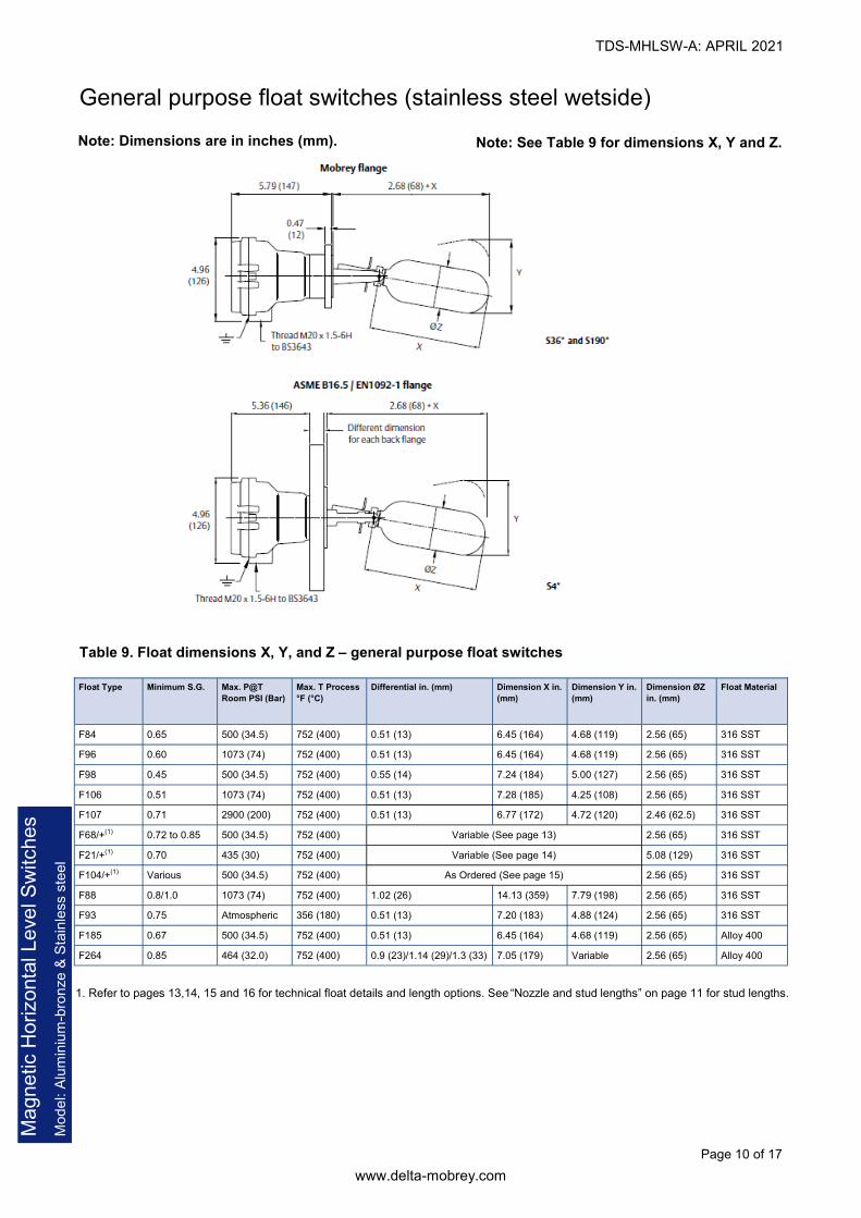
Note: See Table 9 for dimensions X, Y and Z. Note: Dimensions are in inches (mm).
General purpose float switches (stainless steel wetside)
1. Refer to pages 13,14, 15 and 16 for technical float details and length options. See “Nozzle and stud lengths” on page 11 for stud lengths.
Table 9. Float dimensions X, Y, and Z – general purpose float switches
Float Type Minimum S.G. Max. P@T
Room PSI (Bar)
Max. T Process
°F (°C)
Differential in. (mm) Dimension X in.
(mm)
Dimension Y in.
(mm)
Dimension ØZ
in. (mm)
Float Material
F84 0.65 500 (34.5) 752 (400) 0.51 (13) 6.45 (164) 4.68 (119) 2.56 (65) 316 SST
F96 0.60 1073 (74) 752 (400) 0.51 (13) 6.45 (164) 4.68 (119) 2.56 (65) 316 SST
F98 0.45 500 (34.5) 752 (400) 0.55 (14) 7.24 (184) 5.00 (127) 2.56 (65) 316 SST
F106 0.51 1073 (74) 752 (400) 0.51 (13) 7.28 (185) 4.25 (108) 2.56 (65) 316 SST
F107 0.71 2900 (200) 752 (400) 0.51 (13) 6.77 (172) 4.72 (120) 2.46 (62.5) 316 SST
F68/+(1) 0.72 to 0.85 500 (34.5) 752 (400) Variable (See page 13) 2.56 (65) 316 SST
F21/+(1) 0.70 435 (30) 752 (400) Variable (See page 14) 5.08 (129) 316 SST
F104/+(1) Various 500 (34.5) 752 (400) 2.56 (65) 316 SST As Ordered (See page 15)
F88 0.8/1.0 1073 (74) 752 (400) 1.02 (26) 14.13 (359) 7.79 (198) 2.56 (65) 316 SST
F93 0.75 Atmospheric 356 (180) 0.51 (13) 7.20 (183) 4.88 (124) 2.56 (65) 316 SST
F185 0.67 500 (34.5) 752 (400) 0.51 (13) 6.45 (164) 4.68 (119) 2.56 (65) Alloy 400
F264 0.85 464 (32.0) 752 (400) 0.9 (23)/1.14 (29)/1.3 (33) 7.05 (179) Variable 2.56 (65) Alloy 400

TDS-MHLSW-A: APRIL 2021
www.delta-mobrey.com
Page 11 of 17
Magnetic Horizontal Level Switches
Model: Aluminium
-bronze & Stainless steel
Nozzle and stud lengths Table 10. Maximum Length in mm (Dimensions L)
Table 11. Minimum stud projection (in mm)
Companion Flanges
Figure 1. Companion Flanges Mobrey ‘A’ Flanged Switches
Note: Dimensions are in inches (mm).
F68/* F84 F185 F88 F93 F96 F98 F107 F106 F264
Mobrey A 65 75 75 135 75 75 90 - 92 75
DN65 65 75 75 135 - 75 90 - 92 75
DN80 70 80 80 170 - 75 90 - 98 90
DN100 95 105 105 200 - 105 105 - 110 100
DN125 105 140 140 200 - 140 140 - 140 140
DN150 224 180 180 200 - 180 170 - 200 190
3 in. 300/150 70 80 80 170 - 80 90 - 98 90
4 in. 300/150 95 105 105 200 - 105 105 - 110 100
3 in. 600 62 70 70 130 - 70 85 80 89 70
3 in. 900 - - - - 70 - 80 - -
Mobrey A 65 75 75 135 - 75 90 - 92 75
6 in. 150 224 180 180 200 - 180 170 - 200 190
Minimum stud
projection
(See Table 11)
L
(See Table 10)
Rating G A PN 16 PN 40 PN 63 150 600 900 300
Size - - 65 80 100 125 150 65 80 100 125 150 80 100 125 150 3 in. 4 in. 3 in. 4 in. 3 in. 3 in.
Stud 35 30 40 40 40 40 44 42 42 46 52 54 52 55 62 67 46 56 54 56 64 73
TDS-MHLSW-A: APRIL 2021
www.delta-mobrey.com
Page 12 of 17
Magnetic Horizontal Level Switches
Model: Aluminium
-bronze & Stainless steel
50 100 150 200 250 300 350 4000
10
20
30
40
50
60
70
80
90
100
150
200
F88, F96, F106
F107
F21
F68, F84, F98, F104
ANSI CLASS 900
ANSI CLASS 600
ANSI CLASS 300PN64
MOBRE A (GENERAL PURPOSE)
PN40
ANSI CLASS 150
MOBRE A (HOSEPROOF/SUBMERSIBLE)
PN16
50 100 150 200 2500
10
20
30
40
F185 (MONEL)
F264 (MONEL)
PRESSURE (BAR)
TEMPERATURE (°C)
ALUMINIUM BRONZE WETSIDE SWITCHES
F185 (MONEL)
F264 (MONEL)
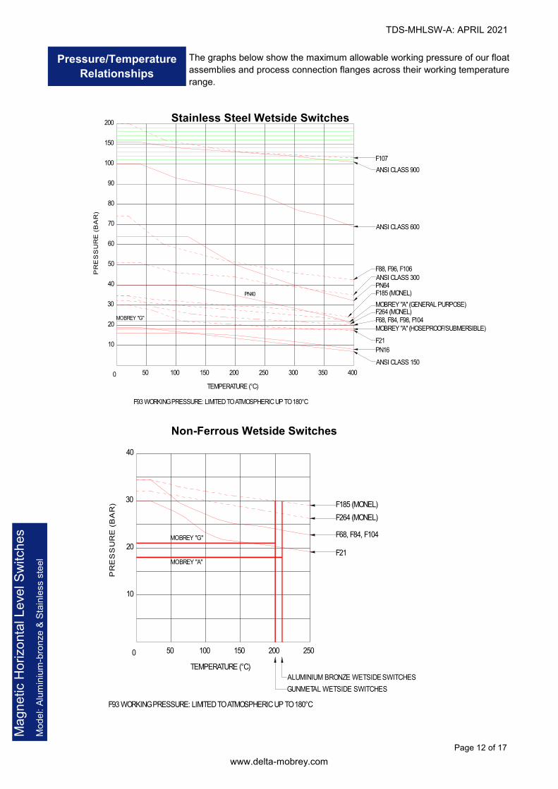
F93 WORKING PRESSURE: LIMITED TO ATMOSPHERIC UP TO 180°C
F21
F68, F84, F104
F93 WORKING PRESSURE: LIMITED TO ATMOSPHERIC UP TO 180°C
TEMPERATURE (°C)
STAINLESS STEEL WETSIDE SWITCHES
NON-FERROUS WETSIDE SWITCHES
PRESSURE (BAR)
MOBRE G
MOBRE A
GUNMETAL WETSIDE SWITCHES
MOBRE G
Pressure/Temperature
Relationships
50 100 150 200 250 300 350 4000
10
20
30
40
50
60
70
80
90
100
150
200
F88, F96, F106
F107
F21
F68, F84, F98, F104
ANSI CLASS 900
ANSI CLASS 600
ANSI CLASS 300PN64
MOBRE A (GENERAL PURPOSE)
PN40
ANSI CLASS 150
MOBRE A (HOSEPROOF/SUBMERSIBLE)
PN16
50 100 150 200 2500
10
20
30
40
F185 (MONEL)
F264 (MONEL)
PRESSURE (BAR)
TEMPERATURE (°C)
ALUMINIUM BRONZE WETSIDE SWITCHES
F185 (MONEL)
F264 (MONEL)
F93 WORKING PRESSURE: LIMITED TO ATMOSPHERIC UP TO 180°C
F21
F68, F84, F104
F93 WORKING PRESSURE: LIMITED TO ATMOSPHERIC UP TO 180°C
TEMPERATURE (°C)
STAINLESS STEEL WETSIDE SWITCHES
NON-FERROUS WETSIDE SWITCHES
PRESSURE (BAR)
MOBRE G
MOBRE A
GUNMETAL WETSIDE SWITCHES
MOBRE G
Non-Ferrous Wetside Switches
Stainless Steel Wetside Switches
The graphs below show the maximum allowable working pressure of our float
assemblies and process connection flanges across their working temperature
range.
TDS-MHLSW-A: APRIL 2021
www.delta-mobrey.com
Page 13 of 17
Magnetic Horizontal Level Switches
Model: Aluminium
-bronze & Stainless steel
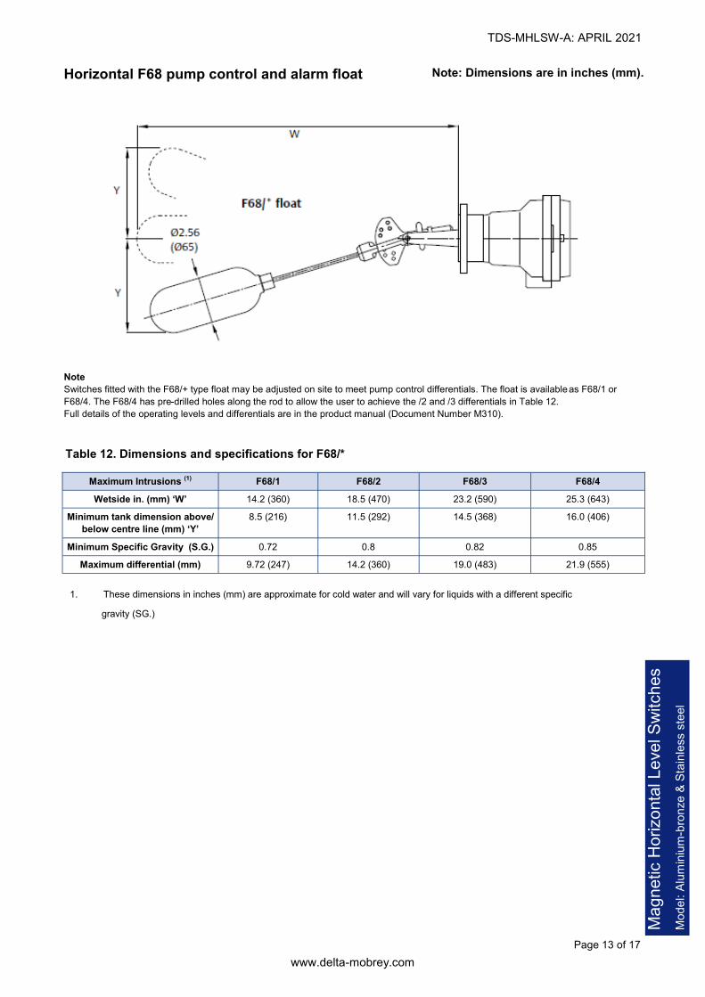
Note: Dimensions are in inches (mm). Horizontal F68 pump control and alarm float
Note
Switches fitted with the F68/+ type float may be adjusted on site to meet pump control differentials. The float is available as F68/1 or
F68/4. The F68/4 has pre-drilled holes along the rod to allow the user to achieve the /2 and /3 differentials in Table 12.
Full details of the operating levels and differentials are in the product manual (Document Number M310).
Table 12. Dimensions and specifications for F68/*
1. These dimensions in inches (mm) are approximate for cold water and will vary for liquids with a different specific
gravity (SG.)
Maximum Intrusions (1) F68/1 F68/2 F68/3 F68/4
Wetside in. (mm) ‘W’ 14.2 (360) 18.5 (470) 23.2 (590) 25.3 (643)
Minimum tank dimension above/
below centre line (mm) ‘Y’
8.5 (216) 11.5 (292) 14.5 (368) 16.0 (406)
Minimum Specific Gravity (S.G.) 0.72 0.8 0.82 0.85
Maximum differential (mm) 9.72 (247) 14.2 (360) 19.0 (483) 21.9 (555)

TDS-MHLSW-A: APRIL 2021
www.delta-mobrey.com
Page 14 of 17
Magnetic Horizontal Level Switches
Model: Aluminium
-bronze & Stainless steel
Figure 2. Pump Control and Alarm Applications
Vertical F21
pump control and alarm float
Note: See Table 13 for dimensions S and T.
Note
Float assembly must be fitted from inside if for use in
a vessel, or complete switch and float assembly may
be mounted on a suitable bracket or manhole cover.
Table 13. Dimensions S and T for F21/+
1. When the maximum rod length is specified.
Float rods may be cut to length on site and switches
set to operate at required level in either pump control
or alarm mode by following the supplied setting in-
structions.
Float rod lengths available:
F21/1 5 ft. (1524 mm)
F21/2 10 ft. (3048 mm)
F21/3 15 ft. (4570 mm) maximum
Alarm level in. (mm) Pump differential ‘S’ in. (mm)
Minimum ’T’ Maximum ‘S’
0.5 to 174.0 (13 to 4420) (1) 6.77 (172) 173.2 (4400) (1)

TDS-MHLSW-A: APRIL 2021
www.delta-mobrey.com
Page 15 of 17
Magnetic Horizontal Level Switches
Model: Aluminium
-bronze & Stainless steel
Table 15. Dimensions A and B with Minimum SG for Horizontally-mounted Switches (Marine Applications)
B
75 100 125 150 175 200 225 250 275 300 325 350 375 400 425 450 475 500 525 550 575 600 625 650 675
A
0 & 75 .67 .67 .68 .68 .69 .69 .70 .71 .72 .73 .73 .74 .75 .76 .77 .78 .79 .79 .80 .81 .82 .83 .84 .85 .86
100 .68 .68 .69 .70 .70 .71 .72 .73 .74 .74 .75 .76 .77 .78 .79 .80 .81 .81 .82 .83 .84 .85 .86 .87
125 .69 .70 .71 .71 .72 .73 .74 .75 .76 .76 .78 .77 .79 .80 .81 .82 .83 .84 .84 .85 .86 .87 .88
150 .71 .71 .72 .73 .74 .75 .76 .77 .78 .78 .79 .80 .81 .82 .83 .84 .85 .86 .87 .88 .89 .89
175 .73 .74 .75 .76 .77 .78 .79 .80 .81 .82 .83 .83 .84 .85 .86 .87 .88 .89 .90 .91
200 .76 .77 .78 .79 .80 .81 .82 .83 .84 .85 .86 .87 .88 .89 .90 .90 .91 .92
225 .79 .80 .81 .82 .83 .84 .85 .86 .86 .87 .88 .89 .90 .91 .92 .93 .94
250 .83 .84 .85 .86 .87 .87 .88 .89 .90 .91 .92 .93 .94 .95 .95
275 .88 .88 .89 .90 .91 .91 .92 .93 .94 .95 .96 .96 .97
300 .93 .93 .93 .93 .94 .95 .95 .96 .97 .98 .99 .99
325 .98 .98 .98 .98 .98 .99 1.0 1.0 1.01 1.02
350 1.04 1.03 1.02 1.03 1.03 1.03 1.04 1.04
375 1.09 1.08 1.07 1.07 1.07 1.08
400 1.15 1.13 1.12 1.12
425 1.20 1.18
Cranked arm floats F104
Note: See Table 14 or Table 15 for dimensions in
A plus B must not exceed
750 mm. A and B should
each be equal to or greater
than 75 mm, unless it is a
straight arm where A is 0
mm (above).
To order, specify the F104 float with these details:
1. A and B (this page) or V and W (next page) dimensions.
(For a straight arm float, state only the ‘B’ dimension).
2. Liquid in contact.
3. Specific Gravity (SG) of liquid.
4. Magnetic switch head type number (e.g. S01DB/F)
5. State land or marine application.
Table 14. Dimensions A and B with Minimum SG for Horizontally-mounted Switches (Land Applications)
B
75 100 125 150 175 200 225 250 275 300 325 400 425 450 475 500 525 550 575 600 625 650 675 350 375
A
0 & 75 .64 .64 .65 .66 .67 .67 .68 .69 .70 .71 .72 .74 .75 .76 .77 .78 .79 .80 .81 .81 .82 .83 .84 .73 .73
100 .64 .65 .66 .67 .68 .69 .70 .70 .71 .72 .73 .76 .77 .78 .79 .79 .80 .81 .82 .83 .84 .85 .74 .75
125 .65 .66 .67 .68 .69 .70 .71 .72 .73 .74 .75 .77 .78 .79 .80 .81 .82 .83 .84 .85 .86 .75 .76
150 .65 .67 .68 .69 .70 .71 .72 .73 .74 .75 .76 .79 .80 .81 .82 .83 .84 .85 .85 .86 .77 .78
175 .66 .67 .69 .70 .71 .72 .73 .74 .75 .76 .77 .80 .81 .82 .83 .84 .85 .86 .87 .78 .79
200 .66 .68 .70 .71 .72 .73 .75 .76 .77 .78 .79 .82 .83 .84 .85 .86 .87 .88 .80 .81
225 .67 .69 .70 .72 .73 .75 .76 .77 .78 .79 .80 .84 .85 .86 .87 .88 .89 .81 .82
250 .67 .69 .71 .73 .74 .76 .77 .78 .80 .81 .82 .85 .86 .87 .88 .89 .83 .84
275 .68 .70 .72 .74 .76 .77 .78 .80 .81 .82 .83 .87 .88 .89 .90 .85 .86
300 .68 .71 .73 .75 .77 .78 .80 .81 .82 .84 .85 .88 .89 .90 .86 .87
325 .69 .71 .74 .76 .78 .80 .81 .83 .84 .85 .86 .90 .91 .88 .89
350 .69 .72 .75 .77 .79 .81 .82 .84 .85 .87 .88 .92 .89 .90
375 .70 .72 .76 .78 .80 .82 .84 .85 .87 .88 .90 .91 .92
400 .71 .73 .76 .79 .81 .83 .85 .87 .88 .90 .91 .92
425 .71 .74 .77 .80 .83 .85 .87 .88 .90 .91 .93
450 .72 .74 .78 .81 .84 .86 .88 .90 .91 .93
475 .72 .75 .79 .82 .85 .87 .89 .91 .93
500 .73 .76 .80 .83 .86 .89 .91 .93
525 .74 .77 .81 .85 .88 .90 .92
550 .74 .77 .81 .86 .89 .92
575 .75 .78 .82 .87 .90
600 .76 .79 .83 .88
625 .76 .80 .84
650 .77 .80
675 .78

TDS-MHLSW-A: APRIL 2021
www.delta-mobrey.com
Page 16 of 17
Magnetic Horizontal Level Switches
Model: Aluminium
-bronze & Stainless steel
Table 17. Dimensions V and W with Minimum SG for Vertically-mounted Switches (Marine Applications)
W
75 100 125 150 175 200 225 250 275 300 325 350 375 400 425 450 475 500 525 550 575 600 625 650 675
V
75 .75 .72 .70 .69 .68 .68 .68 .68 68 .69 .70 .71 .71 .72 .73 .74 .74 .75 .76 .77 .78 .79 .79 .80 .81
100 .76 .72 .70 .68 .67 .68 .68 .68 .69 .70 .70 .71 .72 .73 .73 .74 .75 .76 .77 .77 .78 .79 .80 .81
125 .77 .72 .69 .67 .67 .68 .68 .69 .69 .70 .71 .72 .72 .73 .74 .75 .75 .76 .77 .78 .79 .80 .80
150 .79 .72 .68 .67 .67 .68 .69 .69 .70 .71 .71 .72 .73 .74 .74 .75 .76 .77 .78 .78 .79 .80
175 .71 .67 .67 .68 .68 .69 .70 .70 .71 .72 .73 .73 .74 .75 .76 .76 .77 .78 .79 .79
200 .67 .68 .68 .69 .70 .70 .71 .72 .72 .73 .74 .75 .75 .76 .77 .78 .79 .79
225 .68 .69 .70 .70 .71 .72 .72 .73 .74 .74 .75 .76 .77 .77 .78 .78
250 .69 .70 .70. .71 .71 .72 .73 .74 .74 .75 .76 .77 .77 .78 .78
275 .70 .71 .71 .72 .73 .73 .74 .75 .76 .76 .77 .78 .79
300 .71 .73 .73 .73 .74 .75 .76 .76 .77 .78 .79
325 .73 .73 .74 .75 .75 .76 .77 .78 .78
350 .74 .75 .75 .76 .77 .78 .78
375 .75 .76 .77 .77 .78
400 .77 .77 .78
425 .78
Note: See Table 16 or Table 17 for dimensions in mm.
Table 16. Dimensions V and W with Minimum SG for Vertically-mounted Switches (Land Applications)
B
75 100 125 150 175 200 225 250 275 300 325 400 425 450 475 500 525 550 575 600 625 650 675 350 375
V
75 .67 .67 .66 .66 .66 .66 .67 .67 .68 .68 .68 .71 .72 .73 .73 .74 .75 .76 .77 .77 .78 .79 .80 .70 .70
100 .67 .66 .66 .66 .66 .66 .67 .67 .68 .68 .69 .71 .72 .73 .73 .74 .75 .76 .77 .77 .78 .79 .70 .70
125 .67 .66 .66 .66 .66 .66 .67 .67 .68 .68 .69 .71 .72 .73 .74 .74 .75 .76 .77 .78 .78 .70 .70
150 .67 .66 .66 .66 .66 .66 .67 .67 .68 .68 .69 .71 .72 .73 .74 .74 .75 .76 .77 .78 .70 .71
175 .67 .66 .66 .66 .66 .66 .67 .67 .68 .69 .69 .71 .72 .73 .74 .75 .75 .76 .77 .70 .71
200 .67 .66 .66 .66 .66 .67 .67 .68 .68 .69 .69 .72 .72 .73 .74 .75 .75 .76 .70 .71
225 .66 .66 .66 .66 .66 .67 .67 .68 .68 .69 .70 .72 .72 .73 .74 .75 .76 .70 .71
250 .66 .66 .66 .66 .67 .67 .67 .68 .68 .69 .70 .72 .73 .73 .74 .75 .70 .71
275 .67 .66 .66 .67 .67 .67 .68 .68 .69 .69 .70 .72 .73 .73 .74 .71 .71
300 .67 .67 .66 .67 .67 .67 .68 .68 .69 .69 .70 .72 .73 .74 .71 .71
325 .67 .67 .67 .67 .67 .67 .68 .68 .69 .70 .70 .72 .73 .71 .72
350 .67 .67 .67 .67 .67 .68 .68 .69 .69 .70 .70 .72 .71 .72
375 .68 .67 .67 .67 .67 .68 .68 .69 .69 .70 .71 .71 .72
400 .68 .67 .67 .67 .68 .68 .68 .69 .70 .70 .71 .71
425 .68 .68 .68 .68 .68 .68 .69 .69 .70 .70 .71
450 .68 .68 .68 .68 .68 .68 .69 .69 .70 .71
475 .69 .68 .68 .68 .69 .69 .69 .70 .70
500 .69 .69 .68 .68 .69 .69 .69 .70
525 .69 .69 .69 .69 .69 .69 .70
550 .70 .69 .69 .69 .69 .70
575 .70 .70 .69 .69 .70
600 .70 .70 .70 .70
625 .71 .70 .70
650 .71 .71
675 .72
TDS-MHLSW-A: APRIL 2021
www.delta-mobrey.com
Page 17 of 17
Magnetic Horizontal Level Switches
Model: Aluminium
-bronze & Stainless steel
In the interest of development and improvement Delta Mobrey Ltd, reserves the right to amend, without notice, details contained in this publication. No legal liability will be accepted by Delta Mobrey Ltd for any errors, omissions or amendments.
Delta Mobrey Limited Riverside Business Park, Dogflud Way, Farnham, Surrey GU9 7SS, UK. T+44 (0)1252 729140 F+44 (0)1252 729168 E [email protected] W www.delta-mobrey.com
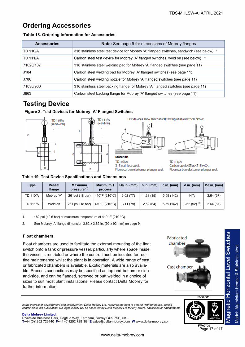
Float chambers
Float chambers are used to facilitate the external mounting of the float
switch onto a tank or pressure vessel, particularly where space inside
the vessel is restricted or where the control must be isolated for rou-
tine maintenance whilst the plant is in operation. A wide range of cast
or fabricated chambers is available. Exotic materials are also availa-
ble. Process connections may be specified as top-and-bottom or side-
and-side, and can be flanged, screwed or butt welded in a choice of
sizes to suit most plant installations. Please contact Delta Mobrey for
further information.
Testing Device Figure 3. Test Devices for Mobrey ‘A’ Flanged Switches
Table 19. Test Device Specifications and Dimensions
1. 182 psi (12.6 bar) at maximum temperature of 410 °F (210 °C).
2. See Mobrey ‘A’ flange dimension 3.62 x 3.62 in, (92 x 92 mm) on page 9.
Type Vessel
flange
Maximum
pressure (1)
Maximum T
process
Øa in. (mm) b in. (mm) c in. (mm) d in. (mm) Øe in. (mm)
TD 110/A Mobrey ‘A’ 261psi (18 bar) 410°F (210°C) 3.02 (77) 1.38 (35) 5.59 (142) N/A 2.64 (67)
TD 111/A Weld on 261 psi (18 bar) 410°F (210°C) 3.11 (79) 2.52 (64) 5.59 (142) 3.62 (92) (2) 2.64 (67)
Table 18. Ordering Information for Accessories
Ordering Accessories
Accessories Note: See page 9 for dimensions of Mobrey flanges
TD 110/A 316 stainless steel test device for Mobrey ‘A’ flanged switches, sandwich (see below) *
TD 111/A Carbon steel test device for Mobrey ‘A’ flanged switches, weld on (see below) *
71020/107 316 stainless steel welding pad for Mobrey ‘A’ flanged switches (see page 11)
J184 Carbon steel welding pad for Mobrey ‘A’ flanged switches (see page 11)
J786 Carbon steel welding nozzle for Mobrey ‘A’ flanged switches (see page 11)
71030/900 316 stainless steel backing flange for Mobrey ‘A’ flanged switches (see page 11)
J863 Carbon steel backing flange for Mobrey ‘A’ flanged switches (see page 11)