TDC4 Temperature Controller Operators Manual Omega at . Your TDC4 Temperature Controller has been...
32
TDC4 Temperature Controller Operator's Manual Copyright © 2010, 2015 Gamry Instruments, Inc. All rights reserved. Printed in the USA. Revision 5.41 July 1, 2015
Transcript of TDC4 Temperature Controller Operators Manual Omega at . Your TDC4 Temperature Controller has been...
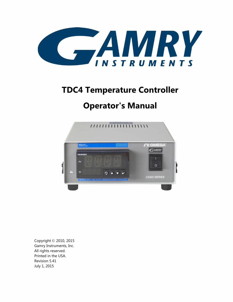
TDC4 Temperature Controller
Operator's Manual
Copyright © 2010, 2015 Gamry Instruments, Inc. All rights reserved. Printed in the USA. Revision 5.41 July 1, 2015
Limited Warranty
Gamry Instruments, Inc. warrants to the original user of this product that it shall be free of defects resulting from faulty manufacture of the product or its components for a period of two years from the date of shipment.
Gamry Instruments, Inc. makes no warranties regarding either the satisfactory performance of the TDC4 Temperature Controller including the software used with this product or the fitness of TDC4 based systems for any particular purpose. The remedy for breach of this Limited Warranty shall be limited solely to repair or by replacement, as determined by Gamry Instruments, Inc., and shall not include other damages.
Gamry Instruments, Inc. reserves the right to make revisions to the TDC4 at any time without incurring any obligation to install same on TDC4s previously purchased. All system specifications are subject to change without notice.
There are no warranties which extend beyond the description herein. This warranty is in lieu of, and excludes any and all other warranties or representations, expressed, implied or statutory, including merchantability and fitness, as well as any and all other obligations or liabilities of Gamry Instruments, Inc., including but not limited to, special or consequential damages.
This limited warranty gives you specific legal rights and you may have others which vary from state to state. Some states do not allow for the exclusion of incidental or consequential damages.
No person, firm or corporation is authorized to assume for Gamry Instruments, Inc. any additional obligation or liability not expressly provided herein except in writing duly executed by an officer of Gamry Instruments, Inc.
If You Have Problems
Contact us at your earliest convenience. We can be contacted via:
Telephone (215) 682-9330 8:00 AM - 6:00 PM US Eastern Standard Time
Fax (215) 682-9331
Email [email protected]
Mail Gamry Instruments, Inc. 734 Louis Drive Warminster, PA 18974 USA
If you write to us about a problem, provide as much information as possible.
If you are having problems in installation or use of this TDC4 Temperature Controller, it would be helpful if you called from a phone next to the instrument, where you can change instrument settings while talking to us.
We will be happy to provide a reasonable level of free support for TDC4 purchasers. Reasonable support includes telephone assistance covering the normal installation, use and simple tuning of the TDC4.

Disclaimers
Gamry Instruments, Inc. cannot guarantee that the TDC4 will work with all computer systems, heaters, cooling devices or cells.
The information in this manual has been carefully checked and is believed to be accurate as of the time of printing. However, Gamry Instruments, Inc. assumes no responsibility for errors that might appear.
Copyrights and Trademarks
TDC4 Operator's Manual Copyright© 1997-2015 Gamry Instruments, Inc. All rights reserved. Printed in USA.
Gamry Framework Software Originally CMS100 Software Copyright© 1989-2015 Gamry Instruments, Inc.
CPT110 Software Originally CMS110 Software Copyright© 1992-2015 Gamry Instruments, Inc.
Explain Computer Language Copyright© 1989-2015 Gamry Instruments, Inc.
Gamry™, Explain™, Gamry Framework™, CPT110™, and TDC4™ are trademarks of Gamry Instruments, Inc.
Microsoft™ is a trademark and Windows® is a registered trademark of Microsoft Corporation.
"DOS" as used herein refers to the MS-DOS and PC-DOS operating systems, which are trademarks of Microsoft Corporation and IBM respectively.
No part of this document may be copied or reproduced in any form without the prior written consent of Gamry Instruments, Inc.

Table of Contents
Limited Warranty ............................................................................................................................................................0-1 If You Have Problems ...................................................................................................................................................0-2 Disclaimers ........................................................................................................................................................................0-3 Copyrights and Trademarks .......................................................................................................................................0-3 Chapter 1 -- Safety Considerations ......................................................................................................................1-1
Introduction .....................................................................................................................................................1-1 Inspection .........................................................................................................................................................1-1 Protective Grounding and Product Safety ...........................................................................................1-1 Line Voltages ...................................................................................................................................................1-2 Switched AC Outlet Fuses ..........................................................................................................................1-2 TDC4 Electrical Outlet Safety ....................................................................................................................1-3 Heater Safety ...................................................................................................................................................1-3 RFI Warning ......................................................................................................................................................1-3 Electrical Transient Sensitivity ...................................................................................................................1-4
Chapter 2 -- Installation .............................................................................................................................................2-1 Initial Visual Inspection ................................................................................................................................2-1 Unpacking Your TDC4 ..................................................................................................................................2-1 Physical Location ............................................................................................................................................2-2 Differences Between an Omega CSi8D and a TDC4 ........................................................................2-2 AC Line Connection ......................................................................................................................................2-2 Power Up Check .............................................................................................................................................2-3 RS232 Cable .....................................................................................................................................................2-3 USB to COM Converters .............................................................................................................................2-4 Connecting the TDC4 to a Heater (and/or Cooler) ..........................................................................2-4 Connecting the TDC4 to an RTD Probe ................................................................................................2-4 Cell Cables from the Potentiostat ...........................................................................................................2-5 Setting up the TDC4 Operating Modes ................................................................................................2-5 Checking TDC4 Operation .........................................................................................................................2-5
Chapter 3 -- Use ............................................................................................................................................................3-1 Using Framework Scripts to Setup and Control Your TDC4 .........................................................3-1 Thermal Design of Your Experiment ......................................................................................................3-1 Tuning the TDC4 Temperature Controller -- Overview ..................................................................3-2 When to Tune..................................................................................................................................................3-2 Restoring Factory Settings .........................................................................................................................3-3 Automatic versus Manual Tuning ...........................................................................................................3-4 Auto Tuning the TDC4 .................................................................................................................................3-5 Manually Tuning the TDC4 ........................................................................................................................3-6
Appendix A - RS232 Cabling and Configuration ...............................................................................................4-1 Appendix B – Default Controller Configuration .................................................................................................4-2
Controller Default Settings ........................................................................................................................4-2 Index ....................................................................................................................................................................................5-1
1 - 1
Chapter 1 -- Safety Considerations
Introduction
The Gamry Instruments TDC4 is based on a standard temperature controller, the Omega Engineering Inc. Model CSi8D. Gamry Instruments has performed slight modifications of this unit to allow easier incorporation of it into an electrochemical test system. Omega provides a User’s Guide that covers safety issues in detail. In most cases, the Omega information will not be duplicated here. If you do not have a copy of this document, it can be obtained by contacting Omega at http://www.omega.com. Your TDC4 Temperature Controller has been supplied in a safe condition. Consult the Omega User’s Guide to insure continued safe operation of this device.
Inspection
When you receive your TDC4 Temperature Controller you should inspect it for evidence of shipping damage. If any damage is noted, please notify Gamry Instruments Inc. and the shipping carrier immediately. Save the shipping container for possible inspection by the carrier.
Warning The protective grounding can be rendered ineffective if the TDC4 is damaged in shipment. Do not operate damaged apparatus until its safety has been verified by a qualified service technician. Tag a damaged TDC4 to indicate that it could be a safety hazard.
Protective Grounding and Product Safety
As defined in IEC Publication 348, Safety Requirements for Electronic Measuring Apparatus, the TDC4 is a Class I apparatus. Class I apparatus is only safe from electrical shock hazards if the case of the apparatus is connected to a protective earth ground. In the TDC4 this protective ground connection is made via the ground prong in the AC line cord. When you use the TDC4 with an approved line cord, the connection to the protective earth ground is automatically made prior to making any power connections. Do not negate the protection of this earth ground by any means. Do not use the TDC4 with a 2 wire extension cord, with an adapter that does not provide for protective grounding, or with an electrical outlet that is not properly wired with a protective earth ground.
Warning If the protective ground is not properly connected, it creates a safety hazard, which could result in personnel injury or death.
1 - 2
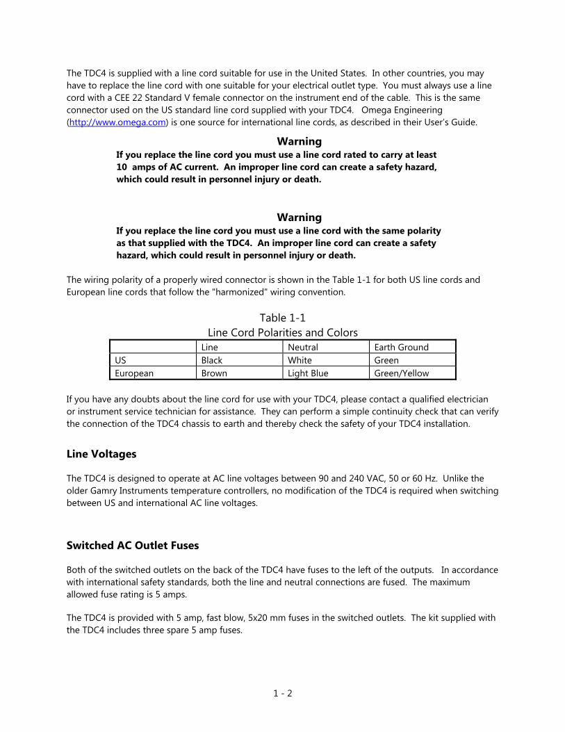
The TDC4 is supplied with a line cord suitable for use in the United States. In other countries, you may have to replace the line cord with one suitable for your electrical outlet type. You must always use a line cord with a CEE 22 Standard V female connector on the instrument end of the cable. This is the same connector used on the US standard line cord supplied with your TDC4. Omega Engineering (http://www.omega.com) is one source for international line cords, as described in their User’s Guide.
Warning If you replace the line cord you must use a line cord rated to carry at least 10 amps of AC current. An improper line cord can create a safety hazard, which could result in personnel injury or death.
Warning If you replace the line cord you must use a line cord with the same polarity as that supplied with the TDC4. An improper line cord can create a safety hazard, which could result in personnel injury or death.
The wiring polarity of a properly wired connector is shown in the Table 1-1 for both US line cords and European line cords that follow the "harmonized" wiring convention.
Table 1-1 Line Cord Polarities and Colors
If you have any doubts about the line cord for use with your TDC4, please contact a qualified electrician or instrument service technician for assistance. They can perform a simple continuity check that can verify the connection of the TDC4 chassis to earth and thereby check the safety of your TDC4 installation.
Line Voltages
The TDC4 is designed to operate at AC line voltages between 90 and 240 VAC, 50 or 60 Hz. Unlike the older Gamry Instruments temperature controllers, no modification of the TDC4 is required when switching between US and international AC line voltages.
Switched AC Outlet Fuses
Both of the switched outlets on the back of the TDC4 have fuses to the left of the outputs. In accordance with international safety standards, both the line and neutral connections are fused. The maximum allowed fuse rating is 5 amps.
The TDC4 is provided with 5 amp, fast blow, 5x20 mm fuses in the switched outlets. The kit supplied with the TDC4 includes three spare 5 amp fuses.
Line Neutral Earth Ground US Black White Green European Brown Light Blue Green/Yellow
1 - 3
You may wish to tailor the fuses in each outlet for the expected load. For example, if you are using a 200 W cartridge heater with a 120 VAC power line, the nominal current is a bit less than 2 amps. You may want to use a 2.5 amp or 3 amp fuse in the switched outlet to the heater. Keeping the fuse rating just above the rated power can prevent or minimize damage to an improperly operated heater.
TDC4 Electrical Outlet Safety
The TDC4 has several switched electrical outlets on the rear panel of its enclosure. These outlets are under the control of the TDC4's controller module or a remote computer. For safety considerations, whenever the TDC4 is powered, you must treat these outlets as being on. Do not trust that the control signals for these outlets, when off, will remain off. Do not touch any wire connected to these outlets unless the TDC4 line cord has been disconnected.
In most cases, the TDC4 will power one or both of these outlets when it is first powered up.
Warning The switched electrical outlets on the TDC4 rear panel must always be treated as on whenever the TDC4 is powered. Remove the TDC4 line cord if you must work with a wire in contact with these outlets.
Heater Safety
The TDC4 Temperature is often used to control an electrical heating apparatus that is located on or very near to an electrochemical cell filled with electrolyte. This can represent a significant safety hazard unless care is taken to insure that the heater has no exposed wires or contacts.
Warning An AC powered heater connected to a cell containing electrolyte can represent a significant electrical shock hazard. Make sure that there are no exposed wires or connections in your heater circuit. Even cracked insulation can be a real hazard when salt water is spilled on a wire.
RFI Warning
Your TDC4 Temperature Controller generates, uses, and can radiate radio frequency energy. The radiated levels are low enough that the TDC4 should present no interference problem in most industrial laboratory environments. The TDC4 may to cause radio frequency interference if operated in a residential environment.

1 - 4
Electrical Transient Sensitivity
Your TDC4 Temperature Controller was designed to offer reasonable immunity from electrical transients. However, in severe cases, the TDC4 could malfunction or even suffer damage from electrical transients. If you are having problems in this regard, the following steps may help:
If the problem is static electricity (sparks are apparent when you touch the TDC4).
• Placing your TDC4 on a static control work surface may help. Static control work surfaces are now generally available from computer supply houses and electronics tool suppliers. An antistatic floor mat may also help, particularly if a carpet is involved in generating the static electricity.
• Air ionizers or even simple air humidifiers can reduce the voltage available in static discharges.
If the problem is AC power line transients (often from large electrical motors near the TDC4).
• Try plugging your TDC4 into a different AC power branch circuit.
• Plug your TDC4 into a power line surge suppresser. Inexpensive surge suppressers are now generally available because of their use with computer equipment.
Contact Gamry Instruments, Inc. if these measures do not solve the problem.
2 - 1
Chapter 2 -- Installation
This chapter covers normal installation of the TDC4 Temperature Controller. The TDC4 was designed to run the experiments in the Gamry Instruments CPT110 Critical Pitting Test System, but it is also useful for other purposes.
The TDC4 is a slightly modified Omega Engineering Inc., Model CSi8D Temperature Controller. Please review the Omega User's Guide to familiarize yourself with the operation of the temperature controller.
Initial Visual Inspection
After you remove your TDC4 from its shipping carton, you should check it for any signs of shipping damage. If any damage is noted, please notify Gamry Instruments, Inc. and the shipping carrier immediately. Save the shipping container for possible inspection by the carrier.
Warning The protective grounding can be rendered ineffective if the TDC4 is damaged in shipment. Do not operate damaged apparatus until its safety has been verified by a qualified service technician. Tag a damaged TDC4 to indicate that it could be a safety hazard.
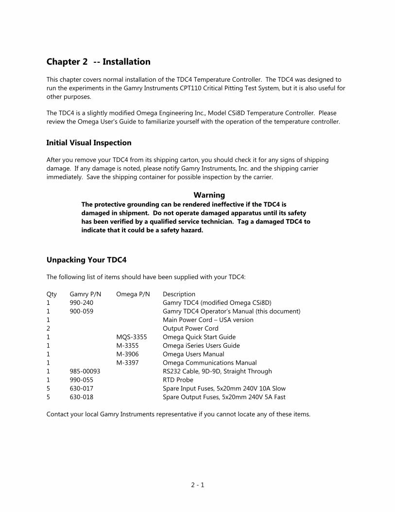
Unpacking Your TDC4
The following list of items should have been supplied with your TDC4: Qty Gamry P/N Omega P/N Description 1 990-240 Gamry TDC4 (modified Omega CSi8D) 1 900-059 Gamry TDC4 Operator’s Manual (this document) 1 Main Power Cord – USA version 2 Output Power Cord 1 MQS-3355 Omega Quick Start Guide 1 M-3355 Omega iSeries Users Guide 1 M-3906 Omega Users Manual 1 M-3397 Omega Communications Manual 1 985-00093 RS232 Cable, 9D-9D, Straight Through 1 990-055 RTD Probe 5 630-017 Spare Input Fuses, 5x20mm 240V 10A Slow 5 630-018 Spare Output Fuses, 5x20mm 240V 5A Fast Contact your local Gamry Instruments representative if you cannot locate any of these items.

2 - 2
Physical Location
You can locate your TDC4 on a normal workbench surface. You will need access to the rear of the instrument because all cable connections are made from the rear. The TDC4 is not restricted to operation in a flat position. You can operate it on its side, or even upside down.
Differences Between an Omega CSi8D and a TDC4
There are only two hardware differences between an unmodified Omega CSi8D temperature controller and a Gamry TDC4.
1) A new connector has been added to the rear panel. It is a 3-pin connector used for a 3-wire 100 Ohm platinum RTD. This connector is placed in a panel opening that is normally used for an optional Ethernet connection.
2) A jumper has been installed between pins 4 and 5 of the rear panel input terminal strip. This jumper configures the RTD input for 3-wire operation.
The RTD connector is wired in parallel with the input terminal strip on the Omega CSi8D. You can still make use of the full range of input connections. If you make other input connections:
• Be careful to avoid connecting two input devices, one to the 3-pin Gamry connector and one to the terminal strip. Unplug the RTD from its connector if you connect any sensor to the input terminal strip.
• You must reconfigure the controller for the alternate input. Consult the Omega manual for additional details.
The firmware configuration settings for the PID (proportional, integrating and derivative) controller in the TDC4 are changed from the Omega defaults. See Appendix B for details. Basically, Gamry’s controller setup includes:
• configuration for operation with a 3-wire 100 Ohm Platinum RTD as the temperature sensor,
• PID tuning values appropriate for a Gamry Instruments Flexcell with a 300 W heating jacket and active cooling through the Flexcell’s heating coil.
AC Line Connection
The TDC4 is designed to operate at AC line voltages between 90 and 240 VAC, 50/60 Hz. You must use a suitable AC power cord to connect the TDC4 to your AC power source. Your TDC4 was shipped with a USA type AC power input cord. If you need a different power cord, you may obtain one locally or contact Omega Engineering Inc (http://www.omega.com). The power cord using with the TDC4 must terminate with a CEE 22 Standard V female connector on the instrument end of the cable and must be rated for 10 amp service.
2 - 3
Warning If you replace the line cord you must use a line cord rated to carry at least 10 amps of AC current. An improper line cord can create a safety hazard, which could result in personnel injury or death.
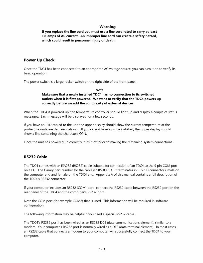
Power Up Check
Once the TDC4 has been connected to an appropriate AC voltage source, you can turn it on to verify its basic operation.
The power switch is a large rocker switch on the right side of the front panel.
Note Make sure that a newly installed TDC4 has no connection to its switched outlets when it is first powered. We want to verify that the TDC4 powers up correctly before we add the complexity of external devices.
When the TDC4 is powered up, the temperature controller should light up and display a couple of status messages. Each message will be displayed for a few seconds.
If you have an RTD cabled to the unit the upper display should show the current temperature at the probe (the units are degrees Celsius). If you do not have a probe installed, the upper display should show a line containing the characters OPN.
Once the unit has powered up correctly, turn it off prior to making the remaining system connections.
RS232 Cable
The TDC4 comes with an EIA232 (RS232) cable suitable for connection of an TDC4 to the 9 pin COM port on a PC. The Gamry part number for the cable is 985-00093. It terminates in 9-pin D connectors, male on the computer end and female on the TDC4 end. Appendix A of this manual contains a full description of the TDC4's RS232 connector. If your computer includes an RS232 (COM) port, connect the RS232 cable between the RS232 port on the rear panel of the TDC4 and the computer’s RS232 port. Note the COM port (for example COM2) that is used. This information will be required in software configuration. The following information may be helpful if you need a special RS232 cable.
The TDC4's RS232 port has been wired as an RS232 DCE (data communications element), similar to a modem. Your computer's RS232 port is normally wired as a DTE (data terminal element). In most cases, an RS232 cable that connects a modem to your computer will successfully connect the TDC4 to your computer.
2 - 4
USB to COM Converters
Most modern PCs do not include COM ports. Fortunately, low cost, easy to use USB to COM adapters/converters are generally available. They plug into a computer’s USB port and have a COM port output. These adapters generally require driver software. The RS232 port can be configured using utilities provided with the driver. Make sure that you know which COM port has been assigned to the adapter.
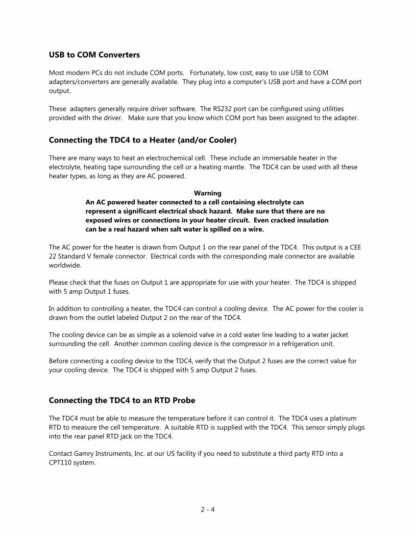
Connecting the TDC4 to a Heater (and/or Cooler)
There are many ways to heat an electrochemical cell. These include an immersable heater in the electrolyte, heating tape surrounding the cell or a heating mantle. The TDC4 can be used with all these heater types, as long as they are AC powered.
Warning An AC powered heater connected to a cell containing electrolyte can represent a significant electrical shock hazard. Make sure that there are no exposed wires or connections in your heater circuit. Even cracked insulation can be a real hazard when salt water is spilled on a wire.
The AC power for the heater is drawn from Output 1 on the rear panel of the TDC4. This output is a CEE 22 Standard V female connector. Electrical cords with the corresponding male connector are available worldwide.
Please check that the fuses on Output 1 are appropriate for use with your heater. The TDC4 is shipped with 5 amp Output 1 fuses.
In addition to controlling a heater, the TDC4 can control a cooling device. The AC power for the cooler is drawn from the outlet labeled Output 2 on the rear of the TDC4.
The cooling device can be as simple as a solenoid valve in a cold water line leading to a water jacket surrounding the cell. Another common cooling device is the compressor in a refrigeration unit.
Before connecting a cooling device to the TDC4, verify that the Output 2 fuses are the correct value for your cooling device. The TDC4 is shipped with 5 amp Output 2 fuses.
Connecting the TDC4 to an RTD Probe
The TDC4 must be able to measure the temperature before it can control it. The TDC4 uses a platinum RTD to measure the cell temperature. A suitable RTD is supplied with the TDC4. This sensor simply plugs into the rear panel RTD jack on the TDC4.
Contact Gamry Instruments, Inc. at our US facility if you need to substitute a third party RTD into a CPT110 system.

2 - 5
The active end of the RTD should be located as close as possible to the working electrode in your cell. This will minimize the effect of thermal gradients on the control accuracy.
Cell Cables from the Potentiostat
A TDC4 in your system does not affect the cell cable connections. These connections are made directly from the potentiostat to the cell. Please read the your potentiostat's Operator's Manual for cell cable instructions.
Setting up the TDC4 Operating Modes
The PID controller built into the TDC4 has a number of different operating modes each of which is configured by means of user entered parameters.
Note: Please refer to the Omega Documentation supplied with your TDC4 for information about the various controller parameters. Do not change a parameter without some knowledge of that parameter's effect on the controller.
The TDC4 is shipped with default settings appropriate for heating and cooling a Gamry Flexcell using a 300 W heating jacket and a solenoid controlled cold water flow for cooling.
Appendix B list the factoryTDC4 settings.
Checking TDC4 Operation
To test the operation of the TDC4, you will run a simple checkout script provided with the CPT110 Critical Pitting Test System. The name of this script is "CHECK110.EXP". Use the procedure in the CPT110 Installation Manual to perform this checkout.

2 - 6
3 - 1
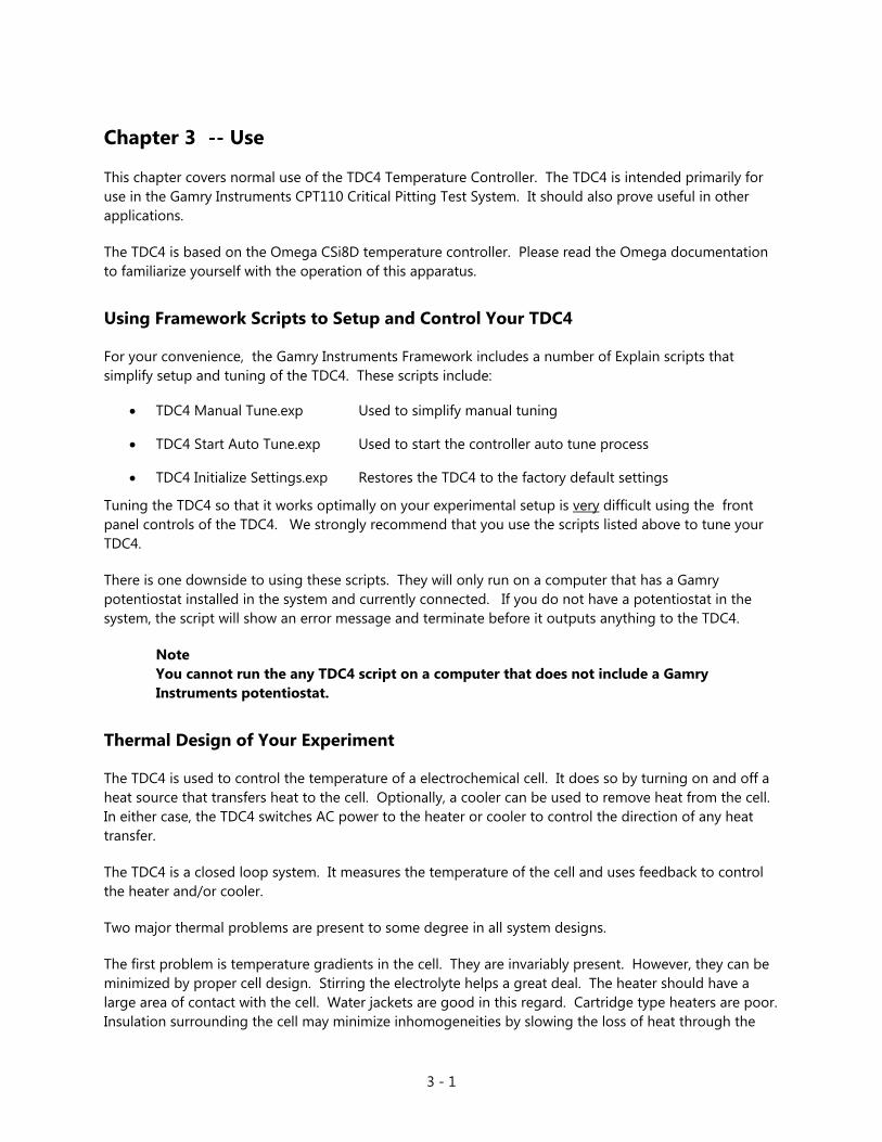
Chapter 3 -- Use
This chapter covers normal use of the TDC4 Temperature Controller. The TDC4 is intended primarily for use in the Gamry Instruments CPT110 Critical Pitting Test System. It should also prove useful in other applications.
The TDC4 is based on the Omega CSi8D temperature controller. Please read the Omega documentation to familiarize yourself with the operation of this apparatus.
Using Framework Scripts to Setup and Control Your TDC4
For your convenience, the Gamry Instruments Framework includes a number of Explain scripts that simplify setup and tuning of the TDC4. These scripts include:
• TDC4 Manual Tune.exp Used to simplify manual tuning
• TDC4 Start Auto Tune.exp Used to start the controller auto tune process
• TDC4 Initialize Settings.exp Restores the TDC4 to the factory default settings
Tuning the TDC4 so that it works optimally on your experimental setup is very difficult using the front panel controls of the TDC4. We strongly recommend that you use the scripts listed above to tune your TDC4.
There is one downside to using these scripts. They will only run on a computer that has a Gamry potentiostat installed in the system and currently connected. If you do not have a potentiostat in the system, the script will show an error message and terminate before it outputs anything to the TDC4.
Note You cannot run the any TDC4 script on a computer that does not include a Gamry Instruments potentiostat.
Thermal Design of Your Experiment
The TDC4 is used to control the temperature of a electrochemical cell. It does so by turning on and off a heat source that transfers heat to the cell. Optionally, a cooler can be used to remove heat from the cell. In either case, the TDC4 switches AC power to the heater or cooler to control the direction of any heat transfer.
The TDC4 is a closed loop system. It measures the temperature of the cell and uses feedback to control the heater and/or cooler.
Two major thermal problems are present to some degree in all system designs.
The first problem is temperature gradients in the cell. They are invariably present. However, they can be minimized by proper cell design. Stirring the electrolyte helps a great deal. The heater should have a large area of contact with the cell. Water jackets are good in this regard. Cartridge type heaters are poor. Insulation surrounding the cell may minimize inhomogeneities by slowing the loss of heat through the

3 - 2
walls of the cell. This is especially true near the working electrode, which may represent the major heat escape pathway. It is not unusual to find the electrolyte temperature near the working electrode is of 5-20 °C lower than that of the bulk of the electrolyte.
If you cannot prevent thermal inhomogenieties, you can at least minimize their effects. One important design consideration is the placement of the RTD used to sense the cell temperature. You should get the RTD as close as possible to the working electrode. This will minimize the error between the actual temperature at the working electrode and the temperature setting.
A second problem concerns the rate of temperature change. You would like to have the rate of heat transfer to the cell's contents high, so that changes in the cell's temperature can be made quickly. A more subtle point is that the rate of heat loss from the cell should also be high. If it is not, the controller risks gross overshoots of the set point temperature when it raises the cell temperature. Ideally, the system will actively cool the cell as well as heat it. Active cooling can consist of a system as simple as tap water flow through a cooling coil and a solenoid valve.
Temperature control via an external heater such as a heating mantle is moderately slow. An internal heater, such as a cartridge heater is often quicker.
Tuning the TDC4 Temperature Controller -- Overview
Closed loop control systems such as the TDC4 must be tuned for optimal performance. A poorly tuned system will suffer from slow response, overshoot and/or poor accuracy. The tuning parameters depend greatly on the characteristics of the system being controlled.
The temperature controller in the TDC4 can be used in an ON/OFF mode or a PID (Proportional, Integral, Derivative) mode. The ON/OFF mode uses hysteresis parameters to control its switching. The PID mode uses tuning parameters. The controller in PID mode reaches the set point temperature quickly without much overshoot and maintains that temperature within a closer tolerance than the ON/OFF mode.
When to Tune
The TDC4 is normally operated in PID (proportional, integrating, derivative) mode. This is a standard method for process control equipment than allows for rapid changes in the set parameter. In this mode the TDC4 must be tuned to match it to the thermal characteristics of the system that it is controlling.
It is shipped configured for PID control mode. You must explicitly change it to operate in any other control mode.
The TDC4 is initially configured with parameters appropriate for a Gamry Instruments Flex Cell heated with a 300 W jacket and cooled using solenoid valve controlling water flow through a cooling coil. The tuning settings are described below:

3 - 3
FACTORY SET TUNING PARAMETERS
You should retune your TDC4 with your cell system before you use it to run any real tests. The system should be retuned whenever you make major changes in the thermal behavior of your system. Typical changes that would require retuning include:
• Changing to a different cell,
• Addition of thermal insulation to the cell,
• Addition of a cooling coil,
• Changing the position or wattage of the heater, or
• Changing from an aqueous electrolyte to an organic electrolyte.
In general you do not have to retune when switching from one aqueous electrolyte to another. Tuning is therefore only an issue when you first set up your system. Once the controller has been tuned for your system, you can ignore tuning as long as your experimental setup remains relatively constant.
Restoring Factory Settings
The TDC4 is configured using close to one hundred settings (fully listed in Appendix B) which can be entered by a complicated user interface using the four buttons on the front of the TDC4. We anticipate that anyone using this interface is likely to scramble the TDC4 settings at least once. Various “automatic” TDC4 operations could also result in incorrect settings, especially if they are interrupted in mid-operation.
Re-entering all the default settings manually would be time consuming and error prone. For this reason, Gamry has provided an Explain script that resets all TDC4 settings to the factory set defaults. Use this procedure to reset the TDC4:
1) Start the Gamry Framework.
2) The Gamry Framework script that resets the TDC4 is “TDC4 Initialize Settings.exp”. Run it by selecting Experiment, Named Script…, TDC4 Initialize Settings.exp from the Framework menu.
3) When this script runs, it displays a dialog similar to that in Figure 3-1.
Parameter (Symbol) Setting Proportional Band 1 9 °C Reset 1 685 seconds Rate 1 109 seconds Cycle Time 1 1 sec Dead Band 14 seconds
3 - 4
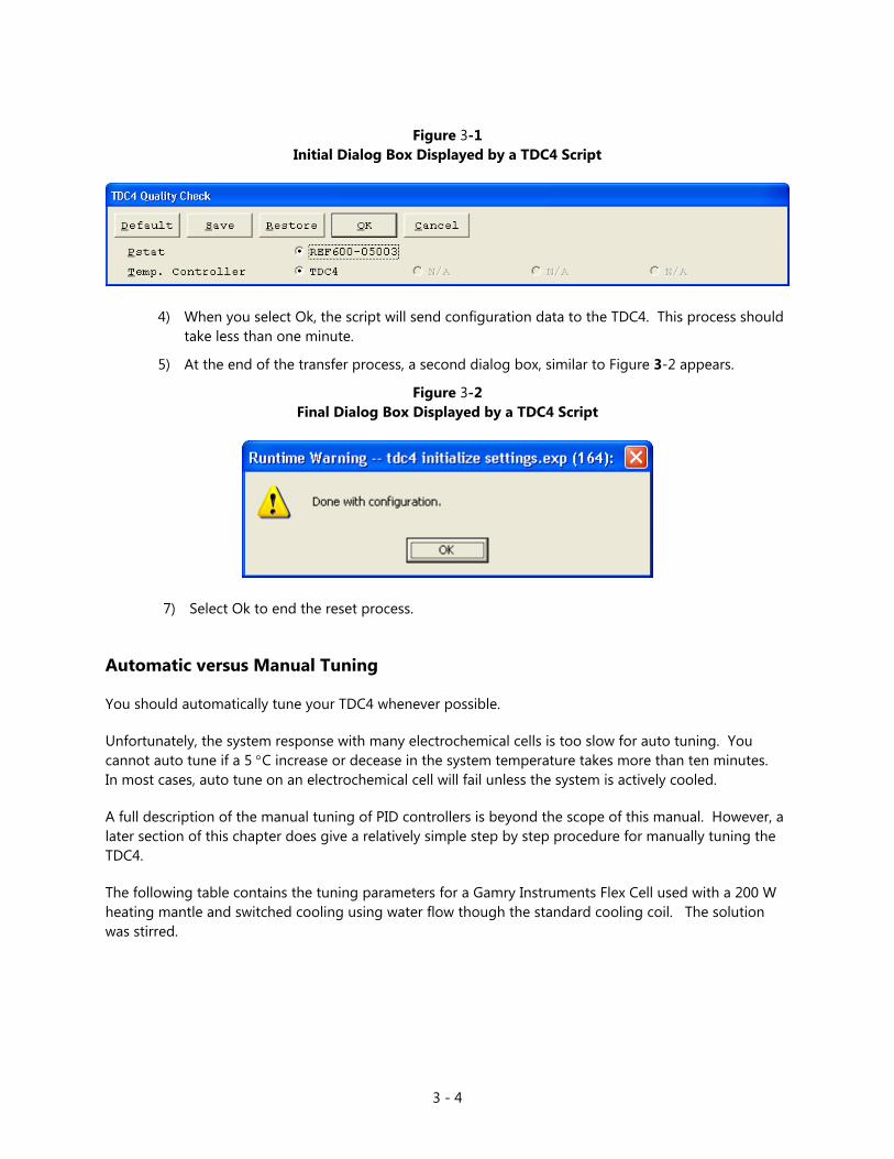
Figure 3-1
Initial Dialog Box Displayed by a TDC4 Script
4) When you select Ok, the script will send configuration data to the TDC4. This process should take less than one minute.
5) At the end of the transfer process, a second dialog box, similar to Figure 3-2 appears.
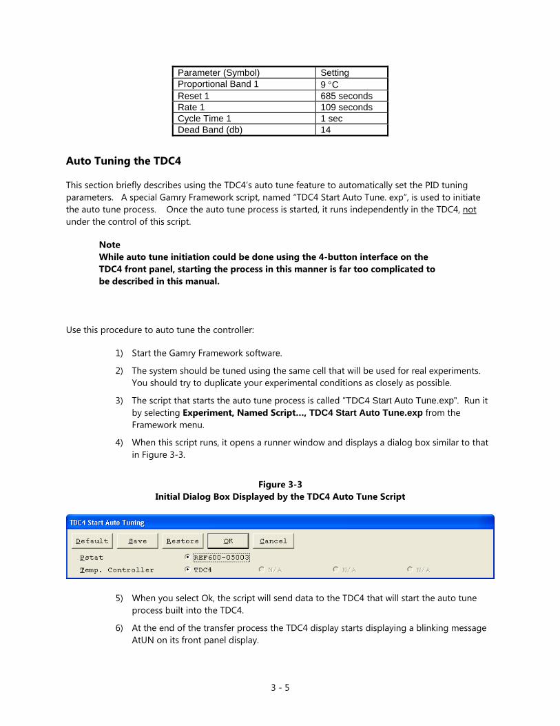
Figure 3-2 Final Dialog Box Displayed by a TDC4 Script
7) Select Ok to end the reset process.
Automatic versus Manual Tuning
You should automatically tune your TDC4 whenever possible.
Unfortunately, the system response with many electrochemical cells is too slow for auto tuning. You cannot auto tune if a 5 °C increase or decease in the system temperature takes more than ten minutes. In most cases, auto tune on an electrochemical cell will fail unless the system is actively cooled.
A full description of the manual tuning of PID controllers is beyond the scope of this manual. However, a later section of this chapter does give a relatively simple step by step procedure for manually tuning the TDC4.
The following table contains the tuning parameters for a Gamry Instruments Flex Cell used with a 200 W heating mantle and switched cooling using water flow though the standard cooling coil. The solution was stirred.
3 - 5
Auto Tuning the TDC4
This section briefly describes using the TDC4’s auto tune feature to automatically set the PID tuning parameters. A special Gamry Framework script, named “TDC4 Start Auto Tune. exp”, is used to initiate the auto tune process. Once the auto tune process is started, it runs independently in the TDC4, not under the control of this script.
Note While auto tune initiation could be done using the 4-button interface on the TDC4 front panel, starting the process in this manner is far too complicated to be described in this manual.
Use this procedure to auto tune the controller:
1) Start the Gamry Framework software.
2) The system should be tuned using the same cell that will be used for real experiments. You should try to duplicate your experimental conditions as closely as possible.
3) The script that starts the auto tune process is called “TDC4 Start Auto Tune.exp”. Run it by selecting Experiment, Named Script…, TDC4 Start Auto Tune.exp from the Framework menu.
4) When this script runs, it opens a runner window and displays a dialog box similar to that in Figure 3-3.
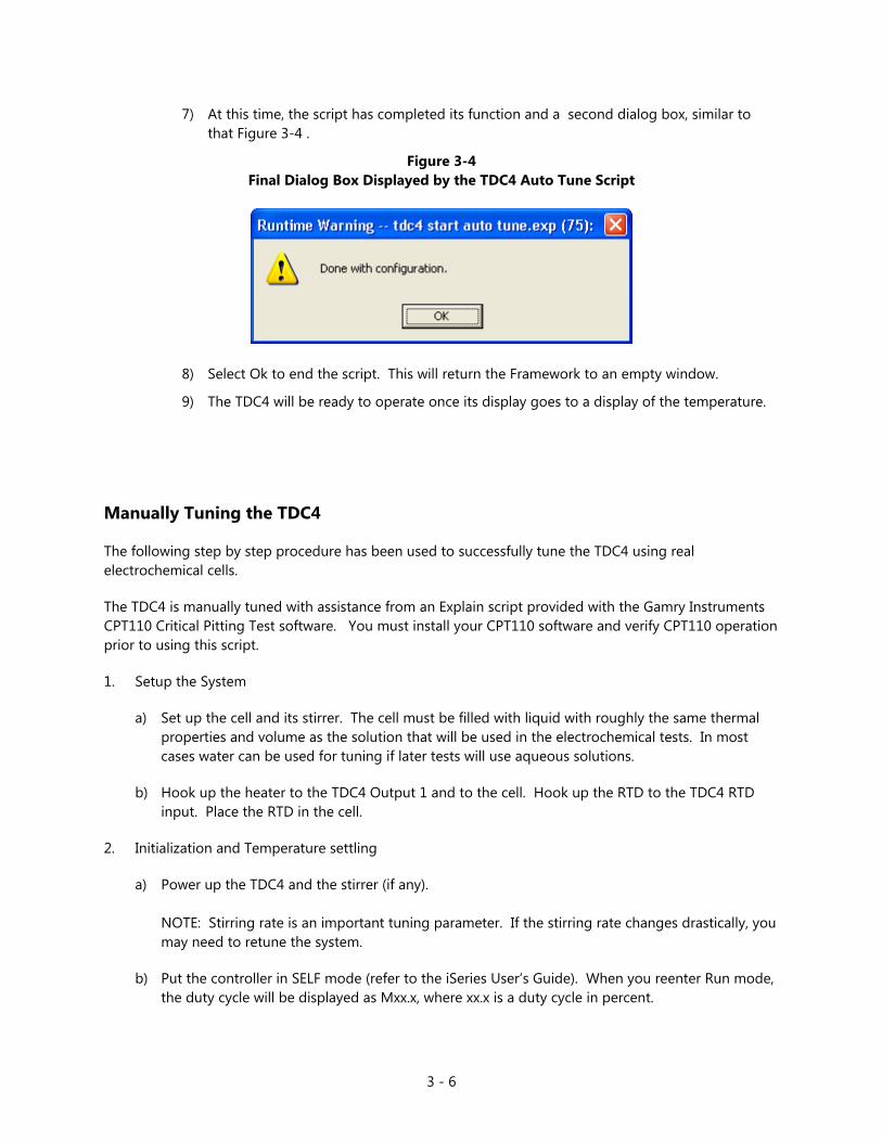
Figure 3-3
Initial Dialog Box Displayed by the TDC4 Auto Tune Script
5) When you select Ok, the script will send data to the TDC4 that will start the auto tune process built into the TDC4.
6) At the end of the transfer process the TDC4 display starts displaying a blinking message AtUN on its front panel display.
Parameter (Symbol) Setting Proportional Band 1 9 °C Reset 1 685 seconds Rate 1 109 seconds Cycle Time 1 1 sec Dead Band (db) 14
3 - 6
7) At this time, the script has completed its function and a second dialog box, similar to that Figure 3-4 .
Figure 3-4 Final Dialog Box Displayed by the TDC4 Auto Tune Script
8) Select Ok to end the script. This will return the Framework to an empty window.
9) The TDC4 will be ready to operate once its display goes to a display of the temperature.
Manually Tuning the TDC4
The following step by step procedure has been used to successfully tune the TDC4 using real electrochemical cells.
The TDC4 is manually tuned with assistance from an Explain script provided with the Gamry Instruments CPT110 Critical Pitting Test software. You must install your CPT110 software and verify CPT110 operation prior to using this script.
1. Setup the System
a) Set up the cell and its stirrer. The cell must be filled with liquid with roughly the same thermal properties and volume as the solution that will be used in the electrochemical tests. In most cases water can be used for tuning if later tests will use aqueous solutions.
b) Hook up the heater to the TDC4 Output 1 and to the cell. Hook up the RTD to the TDC4 RTD input. Place the RTD in the cell.
2. Initialization and Temperature settling
a) Power up the TDC4 and the stirrer (if any). NOTE: Stirring rate is an important tuning parameter. If the stirring rate changes drastically, you may need to retune the system.
b) Put the controller in SELF mode (refer to the iSeries User’s Guide). When you reenter Run mode, the duty cycle will be displayed as Mxx.x, where xx.x is a duty cycle in percent.

3 - 7
c) Enter a small duty cycle into the controller’s display – 5% is a good starting point.
d) In the Gamry Framework, issue the command Experiment, Named Script, TDC4 Manual Tune .exp A display of temperature versus time will be seen.
e) Examine the temperature trend for a few minutes and guess at the final temperature.
f) Adjust the duty cycle so the final temperature is about 5 to 15 °C over ambient temperature.
g) Wait for the system to settle to a constant temperature. This can take several hours.
3) Data Acquisition for Tuning
a) The TDC4 should be in SELF mode and the temperature must be stable. If the TDC4 Manual Tune.exp script is still running, terminate it using the F2-Skip button.
b) Restart the TDC4 Manual Tune .exp Framework script.
c) Record a few hundred seconds of base line data
d) Enter a duty cycle that is about 1.5 times higher than current duty cycle. For example, if the previous power level was 6% increase it to 9%. Note the size of the increase, it will be needed in later calculations.
e) Note the time at which the duty cycle increase occurred.
f) Allow the TDC4 Manual Tune script to acquire at least one hour of data. The temperature versus time curve should start out linear, then begin to curve. See Figure 3-5. This Figure was generated using a Flex Cell heated with a 200 W heating jacket, with slow stirring. The jump in % output was from 6% to 10%. As you can see in this figure, the temperature resolution of the measurement is fairly poor so the temperature versus time curve can consist of just a few levels.
Figure 3-5 Typical Real Time Plot from TDCTUNE.EXP

3 - 8
Wait until some curvature is seen in the temperature versus time curve. Figure 3-1 shows a good quality curve. Select F2-Skip to terminate the experiment.
g) Turn off the heater by setting the power to 0%.
h) Close the CPT110 Runner Window by pressing F2-Skip.
4. Graphing the Temperature versus Time Curve
a) Run Microsoft Excel.
b) Select File, Open... from the Excel menu. In the resulting dialog box, select the "TUNE.DTA" file in your Gamry Framework data directory. Select Ok. NOTE: The data curve resulting from the TDCTUNE experiment is normally stored in the file "TUNE.DTA". If you stored the data in a different file, open that file.
c) The "TUNE.DAT" file is not in an Excel format, so a series of dialog boxes will pop up on the screen. Each dialog box asks a question concerning the format of the file. Select Next> or Finish in each box to accept the default answer to each question.

3 - 9
d) The Excel window should eventually look something like Figure 3-6.
Figure 3-6 TUNE.DTA File in Excel
e) Highlight the first hundred points or so of the two data columns labeled Time and Temp1. These are the point to be included on the graph. You may have to experiment with the number of points that you graph. If you select too many points, you lose resolution in determination of the deadtime (see below). If you select too few points, the slope can be difficult to determine.
f) Select Insert, Chart>, On This Sheet from the Excel menu.
g) Drag the cursor over a blank area of the sheet to define the chart area. The area should be at least 4 columns wide by 10 rows tall.
h) In the next dialog box, select Next> to accept the data range, because you have already highlighted the appropriate data ranges.
i) In the next dialog box, select an XY (Scatter) chart, then select Next>
j) Select any of the linear chart options, then select Next>.
3 - 10
k) Select the default for each of the next dialog boxes.
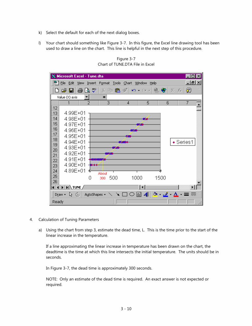
l) Your chart should something like Figure 3-7. In this figure, the Excel line drawing tool has been used to draw a line on the chart. This line is helpful in the next step of this procedure.
Figure 3-7 Chart of TUNE.DTA File in Excel
4. Calculation of Tuning Parameters
a) Using the chart from step 3, estimate the dead time, L. This is the time prior to the start of the linear increase in the temperature. If a line approximating the linear increase in temperature has been drawn on the chart, the deadtime is the time at which this line intersects the initial temperature. The units should be in seconds. In Figure 3-7, the dead time is approximately 300 seconds. NOTE: Only an estimate of the dead time is required. An exact answer is not expected or required.
3 - 11
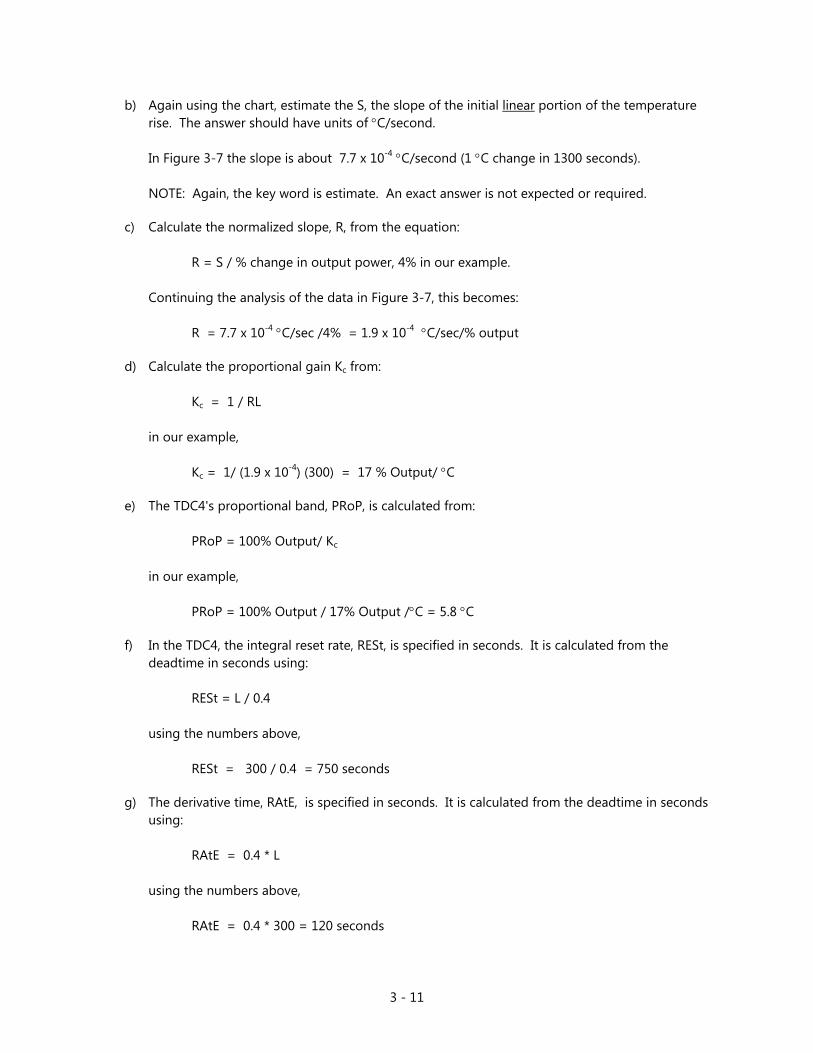
b) Again using the chart, estimate the S, the slope of the initial linear portion of the temperature rise. The answer should have units of °C/second. In Figure 3-7 the slope is about 7.7 x 10⁻⁴ °C/second (1 °C change in 1300 seconds). NOTE: Again, the key word is estimate. An exact answer is not expected or required.
c) Calculate the normalized slope, R, from the equation: R = S / % change in output power, 4% in our example. Continuing the analysis of the data in Figure 3-7, this becomes: R = 7.7 x 10⁻⁴ °C/sec /4% = 1.9 x 10⁻⁴ °C/sec/% output
d) Calculate the proportional gain Kc from: Kc = 1 / RL in our example, Kc = 1/ (1.9 x 10⁻⁴) (300) = 17 % Output/ °C
e) The TDC4's proportional band, PRoP, is calculated from: PRoP = 100% Output/ Kc
in our example,
PRoP = 100% Output / 17% Output /°C = 5.8 °C
f) In the TDC4, the integral reset rate, RESt, is specified in seconds. It is calculated from the deadtime in seconds using: RESt = L / 0.4 using the numbers above, RESt = 300 / 0.4 = 750 seconds
g) The derivative time, RAtE, is specified in seconds. It is calculated from the deadtime in seconds using: RAtE = 0.4 * L using the numbers above, RAtE = 0.4 * 300 = 120 seconds

3 - 12
5. Entering and Checking the New Tuning Parameters
a) The values required by the TDC4 for tuning are PRoP, RESt, and RAtE.
b) Enter the values calculated above into the TDC4 by accessing the CNFG, OUt 1, CtRL menu.
c) Set the controller back to Automatic Mode by changing SELF mode back to dSbL.
d) Enter a setpoint that is 10 to 20 °C above the current temperature.
e) Rerun the "TDCTUNE.EXP" script. A smooth rise in temperature should be seen. A overshoot of 1 or 2 °C is acceptable.
4 - 1
Appendix A - RS232 Cabling and Configuration
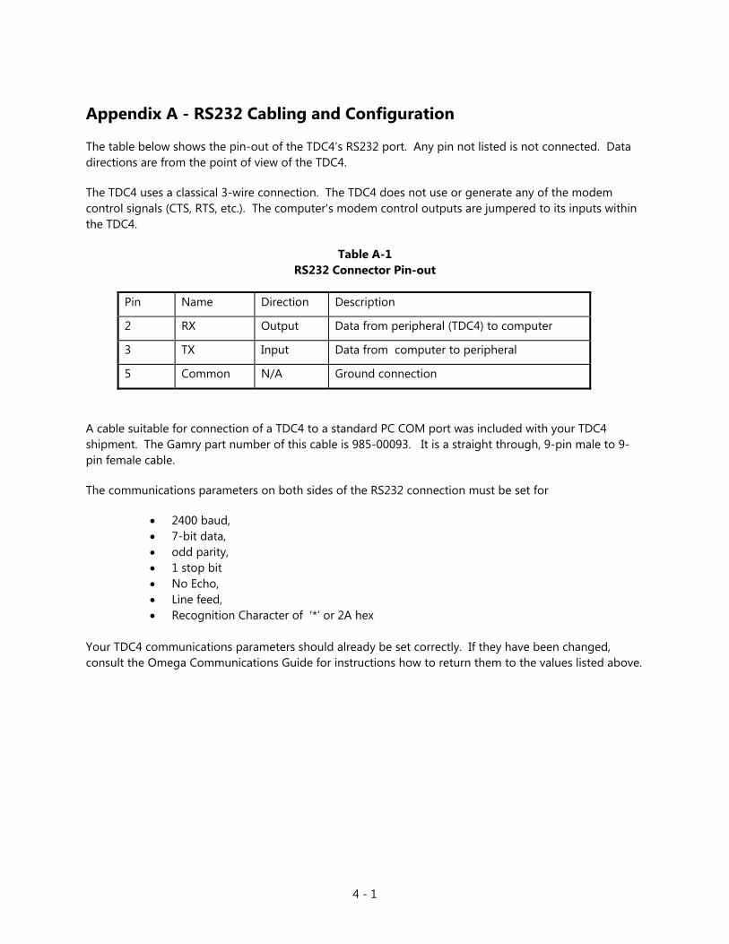
The table below shows the pin-out of the TDC4’s RS232 port. Any pin not listed is not connected. Data directions are from the point of view of the TDC4.
The TDC4 uses a classical 3-wire connection. The TDC4 does not use or generate any of the modem control signals (CTS, RTS, etc.). The computer's modem control outputs are jumpered to its inputs within the TDC4.
Table A-1 RS232 Connector Pin-out
Pin Name Direction Description
2 RX Output Data from peripheral (TDC4) to computer
3 TX Input Data from computer to peripheral
5 Common N/A Ground connection
A cable suitable for connection of a TDC4 to a standard PC COM port was included with your TDC4 shipment. The Gamry part number of this cable is 985-00093. It is a straight through, 9-pin male to 9-pin female cable.
The communications parameters on both sides of the RS232 connection must be set for
• 2400 baud, • 7-bit data, • odd parity, • 1 stop bit • No Echo, • Line feed, • Recognition Character of ‘*’ or 2A hex
Your TDC4 communications parameters should already be set correctly. If they have been changed, consult the Omega Communications Guide for instructions how to return them to the values listed above.
4 - 2
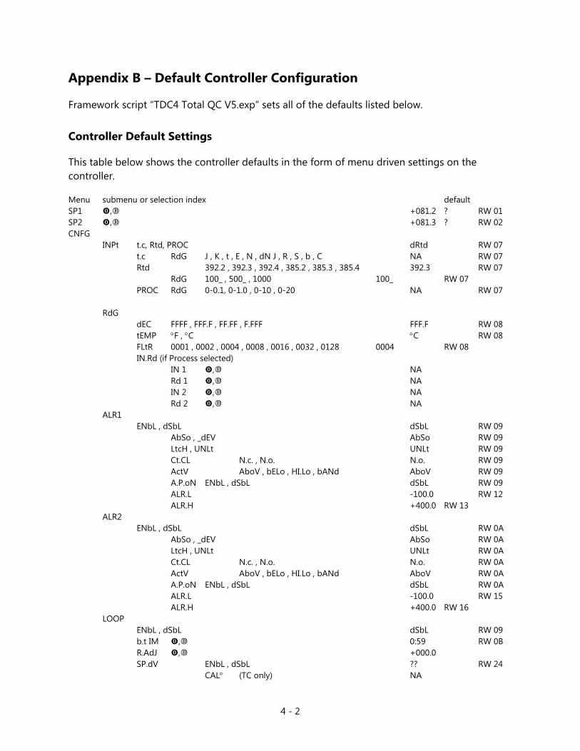
Appendix B – Default Controller Configuration
Framework script “TDC4 Total QC V5.exp” sets all of the defaults listed below.
Controller Default Settings
This table below shows the controller defaults in the form of menu driven settings on the controller. Menu submenu or selection index default SP1 , +081.2 ? RW 01 SP2 , +081.3 ? RW 02 CNFG INPt t.c, Rtd, PROC dRtd RW 07 t.c RdG J , K , t , E , N , dN J , R , S , b , C NA RW 07 Rtd 392.2 , 392.3 , 392.4 , 385.2 , 385.3 , 385.4 392.3 RW 07 RdG 100_ , 500_ , 1000 100_ RW 07 PROC RdG 0-0.1, 0-1.0 , 0-10 , 0-20 NA RW 07
RdG dEC FFFF , FFF.F , FF.FF , F.FFF FFF.F RW 08 tEMP °F , °C °C RW 08 FLtR 0001 , 0002 , 0004 , 0008 , 0016 , 0032 , 0128 0004 RW 08 IN.Rd (if Process selected) IN 1 , NA Rd 1 , NA IN 2 , NA Rd 2 , NA
ALR1 ENbL , dSbL dSbL RW 09 AbSo , _dEV AbSo RW 09 LtcH , UNLt UNLt RW 09 Ct.CL N.c. , N.o. N.o. RW 09 ActV AboV , bELo , HI.Lo , bANd AboV RW 09 A.P.oN ENbL , dSbL dSbL RW 09 ALR.L -100.0 RW 12 ALR.H +400.0 RW 13 ALR2 ENbL , dSbL dSbL RW 0A AbSo , _dEV AbSo RW 0A LtcH , UNLt UNLt RW 0A Ct.CL N.c. , N.o. N.o. RW 0A ActV AboV , bELo , HI.Lo , bANd AboV RW 0A A.P.oN ENbL , dSbL dSbL RW 0A ALR.L -100.0 RW 15 ALR.H +400.0 RW 16 LOOP ENbL , dSbL dSbL RW 09 b.t IM , 0:59 RW 0B R.AdJ , +000.0
SP.dV ENbL , dSbL ?? RW 24 CAL° (TC only) NA

4 - 3
OUt1 SELF ENbL , dSbL ENbL RW 24 o°LO , 0% RW 27 o°HI , 99% RW 28 CtRL ON.OF , PId PId RW 0C ActN dRct , RVRS RVRS RW 0C AUto (if PId was selected) ENbL , dSbL dSbL RW 0C ANtL ENbL , dSbL ENbL RW 0C StRt (if AUto enabled) ENbL , dSbL dSbL RW 0C PRoP (if Auto PID is disabled) , 09.0 RW 17 RESt , 685.0 RW 18 RAtE , 109.0 RW 19 CyCL , 01 RW 1A dPNG 0000 , 0001 , 0002 , 0003 , 0004 , 0005 , 0006 , 0007 0003 RW 0D dEAd (if ON/OFF selected) , 014.0 RW 17 OUt2 CtRL ON.OF , PId ON.OF RW 0D ActN dRct , RVRS dRct RW 0D CyCL , 05 RW 1D dEAd (if ON/OFF selected) , 014.0 RW 1C RAMP
ENbL , dSbL (Alarm must be Disabled if Ramp is Enabled) dSbL RW 0D , 00:00 RW 0E SOAK ENbL , dSbL dSbL RW 0D , 00:00 RW 1E Id , 0000 RW 05 CH.Id , 0000 FULL ENbL , dSbL dSbL RW 24 SP.Id ENbL , dSbL dSbL RW 24
4 - 4
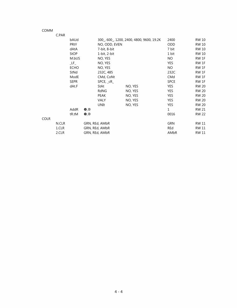
COMM C.PAR
bAUd 300_, 600_, 1200, 2400, 4800, 9600, 19.2K 2400 RW 10 PRtY NO, ODD, EVEN ODD RW 10 dAtA 7-bit, 8-bit 7 bit RW 10 StOP 1-bit, 2-bit 1 bit RW 10 M.bUS NO, YES NO RW 1F _LF_ NO, YES YES RW 1F
ECHO NO, YES NO RW 1F StNd 232C, 485 232C RW 1F ModE CMd, CoNt CMd RW 1F SEPR SPCE, _cR_ SPCE RW 1F dAt.F StAt NO, YES YES RW 20 RdNG NO, YES YES RW 20 PEAK NO, YES YES RW 20 VALY NO, YES YES RW 20 UNIt NO, YES YES RW 20 AddR , 1 RW 21 tR.tM , 0016 RW 22 COLR N.CLR GRN, REd, AMbR GRN RW 11 1.CLR GRN, REd, AMbR REd RW 11 2.CLR GRN, REd, AMbR AMbR RW 11
5 - 1
Index
AC line cord, 1-1 AC Outlet Fuses, 1-2 auto tune, 3-4 Cabling, 2-3 Cell Cables, 2-4 cooler, 2-4 electrical transients, 1-3 fuse
cooler, 2-4 heater, 2-4
heater, 2-4 modem cable, 2-3 Omega CSi8D, 2-5 Omega CSi8D Temperature Controller, 2-1, 3-1 Output 1, 2-4 Output 2, 2-4 Parameters
Operating, 3-2 power line transient, 1-4 Product Safety, 1-1 protective grounding, 1-1 RFI, 1-3 RS232 cable, 2-3 RTD, 2-4 safety, 1-1 shipping damage, 1-1 static electricity, 1-3 TDC4
Cabling, 2-3 Cell Connections, 2-4 Checkout, 2-5 Operating Modes, 2-5 Tuning, 3-2
Thermal Design, 3-1
Use
TDC4, 3-1 Visual Inspection, 2-1