TDC BDC- TDC 444 Engine.pdf · The Four Cylinder Cycle-JCB 444 Engine The four stroke cycle of the...
5
Section 4 - Systems Description Engine Overview The Four Stroke Cycle The Four Stroke Cycle 1 Induction As the piston travels down the cylinder it draws filtered air at atmospheric pressure and ambient temperature through an air filter and inlet valves into the cylinder. 2 Compression When the piston reaches the bottom of its stroke the inlet valves close. The piston then starts to rise up the cylinder compressing the air trapped in the cylinder. This causes the temperature and pressure of the air to rise. Fuel is injected into the cylinder when the piston is near to top dead centre. 3 Power The piston continues to rise after the start of fuel injection causing a further increase in pressure and BDC- temperature. The temperature rises to a point at which the fuel/air mixture ignites. A cylinder is said to be 'firing' when the fuel/air mixture ignites. This combustion causes a very rapid rise in both temperature and pressure. The high pressure generated propels the piston downward turning the crankshaft and producing energy. 4 Exhaust TDC TDC Fig 8. Once the piston has reached the bottom of its travel, the exhaust valves open and momentum stored in the flywheel forces the piston up the cylinder expelling the exhaust gases. In a running engine these four phases are continuously repeated. Each stroke is half a revolution of the crankshaft, thus, in one cycle of a four stroke engine, the crankshaft revolves twice. 746030 4-14 9806/3000-04 4-14
Transcript of TDC BDC- TDC 444 Engine.pdf · The Four Cylinder Cycle-JCB 444 Engine The four stroke cycle of the...
Section 4 - Systems Description Engine Overview
The Four Stroke Cycle
The Four Stroke Cycle
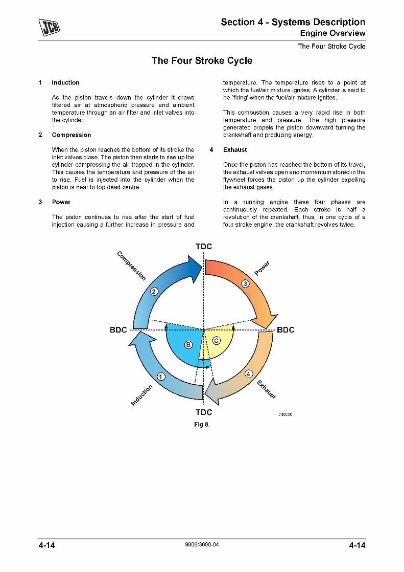
1 Induction
As the piston travels down the cylinder it draws filtered air at atmospheric pressure and ambient temperature through an air filter and inlet valves into the cylinder.
2 Compression
When the piston reaches the bottom of its stroke the inlet valves close. The piston then starts to rise up the cylinder compressing the air trapped in the cylinder. This causes the temperature and pressure of the air to rise. Fuel is injected into the cylinder when the piston is near to top dead centre.
3 Power
The piston continues to rise after the start of fuel injection causing a further increase in pressure and
BDC-
temperature. The temperature rises to a point at which the fuel/air mixture ignites. A cylinder is said to be 'firing' when the fuel/air mixture ignites.
This combustion causes a very rapid rise in both temperature and pressure. The high pressure generated propels the piston downward turning the crankshaft and producing energy.
4 Exhaust
TDC
TDC Fig 8.
Once the piston has reached the bottom of its travel, the exhaust valves open and momentum stored in the flywheel forces the piston up the cylinder expelling the exhaust gases.
In a running engine these four phases are continuously repeated. Each stroke is half a revolution of the crankshaft, thus, in one cycle of a four stroke engine, the crankshaft revolves twice.
746030
4-14 9806/3000-04 4-14
2
c
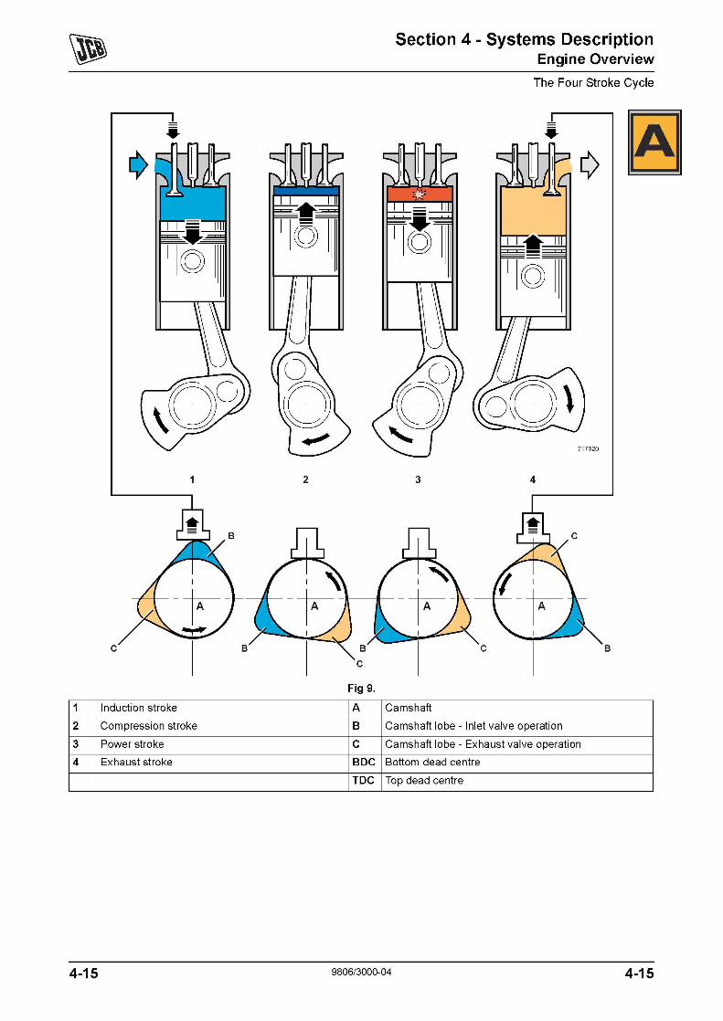
1 Induction stroke
2 Compression stroke
3 Power stroke
4 Exhaust stroke
4-15
Fig 9.
A
B
c BDC
TDC
Section 4 - Systems Description Engine Overview
The Four Stroke Cycle
717620
3 4
B
Camshaft
Camshaft lobe- Inlet valve operation
Camshaft lobe- Exhaust valve operation
Bottom dead centre
Top dead centre
9806/3000-04 4-15

Camshaft and Valve Operation
As the crankshaft rotates the camshaft also rotates, driven by a gear on the crankshaft. The inlet and exhaust valves are opened by lobes on the camshaft in time with the cycle. The diagrams show the position of the camshaft at each part of the four stroke cycle. It can be seen that for a complete cycle the camshaft revolves once. Since the crankshaft revolves twice during the cycle it follows that the camshaft is driven at half crankshaft (engine) speed.
4-16 9806/3000-04
Section 4 - Systems Description Engine Overview
The Four Stroke Cycle
4-16
Section 4 - Systems Description Engine Overview
The Four Cylinder Cycle- JCB 444 Engine
The Four Cylinder Cycle- JCB 444 Engine
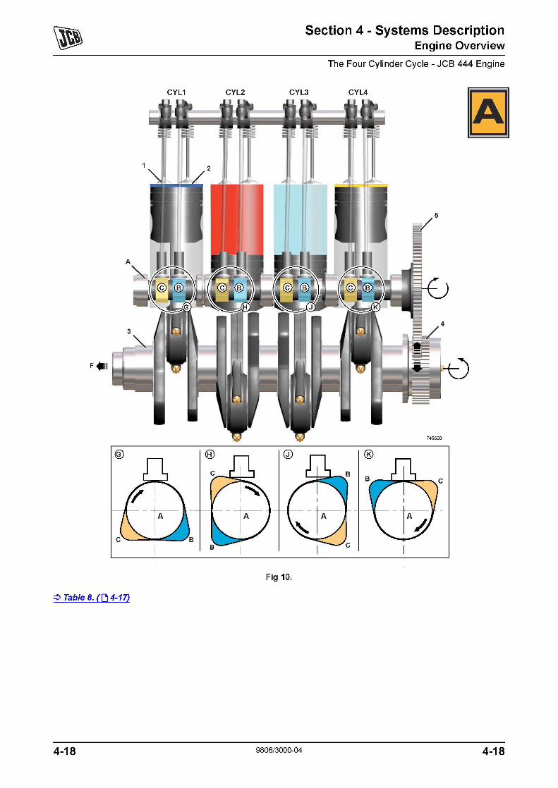
The four stroke cycle of the JCB 444 engine is as described in The Four Stroke Cycle :::::>The Four Stroke Cycle ([j 4-14) . This section describes the cycle sequence for the 4 cylinders of the engine.
:::::>Fig 10. ([j 4-18)
With the crankshaft positioned as shown the pistons in numbers 1 and 4 cylinders are at top dead centre and pistons in numbers 2 and 3 cylinders are at bottom dead centre.
Cylinder Number 1 -
The piston is at the top of its Compression stroke and is about to start its Power stroke.
Cylinder Number 2 -
The piston is at the bottom of its Power stroke and is about to start its Exhaust stroke.
Cylinder Number 3 -
The piston is at the bottom of its Induction stroke and is about to start its Compression stroke.
Cylinder Number 4-
The piston is at the top of its Exhaust stroke and is about to start its Induction stroke.
Firing Order
A cylinder is said to be 'firing' when the fuel/air mixture ignites and the piston is about to start its power stroke.
It is important to note that number 1 cylinder is 'firing' and about to start its Power stroke. Rotating the crankshaft a further 360 degrees would position the pistons as described but the engine would be at a different stage in its four stroke cycle, with number 1 cylinder about to start its Induction stroke.
The stages in the four stroke cycle for each cylinder are as follows:
Valve Operation Inlet and exhaust valves closed
Valve Operation Inlet valves closed, exhaust valves about to open
Valve Operation Exhaust valves closed, inlet valves about to close
Valve Operation Exhaust valves about to close, inlet valves about to open
From the stages described it can be seen that number 1 cylinder will be next to fire. Number 3 cylinder is starting its compression stroke and is next in the cycle, followed by cylinders 4 and 2.
The firing order is therefore; 1, 3, 4, 2.
Table 8. Key :::::>Fig 10. ([j 4-181
CYL1 Cylinder number 1 A Camshaft
CYL2 Cylinder number 2 B Camshaft lobe- Inlet valve operation
CYL3 Cylinder number 3 c Camshaft lobe- Exhaust valve operation
CYL4 Cylinder number 4 F Front of engine
1 Exhaust valves
2 Inlet valves
3 Crankshaft
4 Crankshaft gear
5 Camshaft drive gear
4-17 9806/3000-04 4-17
CYL1 CYL2
:::::> Table 8. ([j 4-17)
4-18
Section 4 - Systems Description Engine Overview
The Four Cylinder Cycle- JCB 444 Engine
CYL3 CYL4
Fig 10.
9806/3000-04 4-18