TCX Series Optical Transport System Feature Guide · •...
128
TCX Series Optical Transport System Feature Guide Modified: 2018-06-18 Copyright © 2018, Juniper Networks, Inc.
Transcript of TCX Series Optical Transport System Feature Guide · •...

TCX Series Optical Transport System FeatureGuide
Modified: 2018-06-18
Copyright © 2018, Juniper Networks, Inc.

Juniper Networks, Inc.1133 InnovationWaySunnyvale, California 94089USA408-745-2000www.juniper.net
Juniper Networks, the Juniper Networks logo, Juniper, and Junos are registered trademarks of Juniper Networks, Inc. and/or its affiliates inthe United States and other countries. All other trademarks may be property of their respective owners.
Juniper Networks assumes no responsibility for any inaccuracies in this document. Juniper Networks reserves the right to change, modify,transfer, or otherwise revise this publication without notice.
TCX Series Optical Transport System Feature GuideCopyright © 2018 Juniper Networks, Inc. All rights reserved.
The information in this document is current as of the date on the title page.
YEAR 2000 NOTICE
Juniper Networks hardware and software products are Year 2000 compliant. Junos OS has no known time-related limitations through theyear 2038. However, the NTP application is known to have some difficulty in the year 2036.
ENDUSER LICENSE AGREEMENT
The Juniper Networks product that is the subject of this technical documentation consists of (or is intended for use with) Juniper Networkssoftware. Use of such software is subject to the terms and conditions of the End User License Agreement (“EULA”) posted athttps://www.juniper.net/support/eula/. By downloading, installing or using such software, you agree to the terms and conditions of thatEULA.
Copyright © 2018, Juniper Networks, Inc.ii

Table of Contents
About the Documentation . . . . . . . . . . . . . . . . . . . . . . . . . . . . . . . . . . . . . . . . . . . . xiii
Documentation and Release Notes . . . . . . . . . . . . . . . . . . . . . . . . . . . . . . . . . xiii
Documentation Conventions . . . . . . . . . . . . . . . . . . . . . . . . . . . . . . . . . . . . . . xiii
Documentation Feedback . . . . . . . . . . . . . . . . . . . . . . . . . . . . . . . . . . . . . . . . . xv
Requesting Technical Support . . . . . . . . . . . . . . . . . . . . . . . . . . . . . . . . . . . . . xvi
Self-Help Online Tools and Resources . . . . . . . . . . . . . . . . . . . . . . . . . . . xvi
Opening a Case with JTAC . . . . . . . . . . . . . . . . . . . . . . . . . . . . . . . . . . . . . xvi
Chapter 1 Getting Started . . . . . . . . . . . . . . . . . . . . . . . . . . . . . . . . . . . . . . . . . . . . . . . . . . . 19
About TCX Series Optical Transport System . . . . . . . . . . . . . . . . . . . . . . . . . . . . . . 19
TCX1000 Programmable ROADM . . . . . . . . . . . . . . . . . . . . . . . . . . . . . . . . . . 19
TCX1000-2D8CMD . . . . . . . . . . . . . . . . . . . . . . . . . . . . . . . . . . . . . . . . . . . . . . 19
proNX Optical Director . . . . . . . . . . . . . . . . . . . . . . . . . . . . . . . . . . . . . . . . . . . 20
Understanding TCX Series Terminology . . . . . . . . . . . . . . . . . . . . . . . . . . . . . . . . . . 21
Chapter 2 Safety . . . . . . . . . . . . . . . . . . . . . . . . . . . . . . . . . . . . . . . . . . . . . . . . . . . . . . . . . . . 23
Optical Precautions . . . . . . . . . . . . . . . . . . . . . . . . . . . . . . . . . . . . . . . . . . . . . . . . . 23
TCX1000-RDM20 Automatic Laser Shutdown . . . . . . . . . . . . . . . . . . . . . . . . . . . 24
Automatic Line Shutoff . . . . . . . . . . . . . . . . . . . . . . . . . . . . . . . . . . . . . . . . . . 24
Automatic Power Reduction . . . . . . . . . . . . . . . . . . . . . . . . . . . . . . . . . . . . . . . 25
Output Power Clamp . . . . . . . . . . . . . . . . . . . . . . . . . . . . . . . . . . . . . . . . . . . . 25
Chapter 3 TCX1000 Series Product Overviews . . . . . . . . . . . . . . . . . . . . . . . . . . . . . . . . . 27
TCX1000 Programmable ROADM Overview . . . . . . . . . . . . . . . . . . . . . . . . . . . . . . 27
TCX1000-RDM20 Features . . . . . . . . . . . . . . . . . . . . . . . . . . . . . . . . . . . . . . . . . . . 28
20-Port Route and Select ROADM . . . . . . . . . . . . . . . . . . . . . . . . . . . . . . . . . . 28
Complete End-to-End Juniper Networks Coherent Packet-Optical
Solution . . . . . . . . . . . . . . . . . . . . . . . . . . . . . . . . . . . . . . . . . . . . . . . . . . . 29
TCX1000-RDM20 Colorless, Directionless, Contentionless Operation . . . . . 29
Integrated Optical Amplification . . . . . . . . . . . . . . . . . . . . . . . . . . . . . . . . . . . 30
Support for Multiple Fiber Types . . . . . . . . . . . . . . . . . . . . . . . . . . . . . . . . . . . 30
Integrated Optical Supervisory Channel . . . . . . . . . . . . . . . . . . . . . . . . . . . . . 30
Automatic Laser Shutdown . . . . . . . . . . . . . . . . . . . . . . . . . . . . . . . . . . . . . . . 30
Performance Monitoring . . . . . . . . . . . . . . . . . . . . . . . . . . . . . . . . . . . . . . . . . . 30
TCX1000-RDM20 Management Features . . . . . . . . . . . . . . . . . . . . . . . . . . . . 31
Ports . . . . . . . . . . . . . . . . . . . . . . . . . . . . . . . . . . . . . . . . . . . . . . . . . . . . . . . . . . 31
TCX1000-2D8CMD Colorless Multiplexer-Demultiplexer Overview . . . . . . . . . . . 32
TCX1000-2D8CMD Overview . . . . . . . . . . . . . . . . . . . . . . . . . . . . . . . . . . . . . . 32
Client Ports . . . . . . . . . . . . . . . . . . . . . . . . . . . . . . . . . . . . . . . . . . . . . . . . . . . . 32
Line Ports . . . . . . . . . . . . . . . . . . . . . . . . . . . . . . . . . . . . . . . . . . . . . . . . . . . . . . 32
Single Direction Add/Drop Colorless Multiplexing . . . . . . . . . . . . . . . . . . 33
1 + 1 Redundancy . . . . . . . . . . . . . . . . . . . . . . . . . . . . . . . . . . . . . . . . . . . . 33
iiiCopyright © 2018, Juniper Networks, Inc.

Operation . . . . . . . . . . . . . . . . . . . . . . . . . . . . . . . . . . . . . . . . . . . . . . . . . . . . . 34
TCX1000-2D8CMD Configurations . . . . . . . . . . . . . . . . . . . . . . . . . . . . . . . . . 34
Example 1 . . . . . . . . . . . . . . . . . . . . . . . . . . . . . . . . . . . . . . . . . . . . . . . . . . 34
Example 2 . . . . . . . . . . . . . . . . . . . . . . . . . . . . . . . . . . . . . . . . . . . . . . . . . . 35
TCX1000-2D8CMD Configuration Considerations . . . . . . . . . . . . . . . . . . . . . 35
TCX1000-RDM20 Optical Monitoring Points . . . . . . . . . . . . . . . . . . . . . . . . . . . . . 36
Chapter 4 Optical Control and Management Overview . . . . . . . . . . . . . . . . . . . . . . . . . . 37
proNX Optical Director System and Optical Control Levels . . . . . . . . . . . . . . . . . . 37
Introduction . . . . . . . . . . . . . . . . . . . . . . . . . . . . . . . . . . . . . . . . . . . . . . . . . . . . 37
System Controls . . . . . . . . . . . . . . . . . . . . . . . . . . . . . . . . . . . . . . . . . . . . . . . . 38
Optical Control Levels . . . . . . . . . . . . . . . . . . . . . . . . . . . . . . . . . . . . . . . . . . . 38
proNX Optical Director Overview . . . . . . . . . . . . . . . . . . . . . . . . . . . . . . . . . . . . . . 39
proNX Optical Director Control and Management Software Components . . . . . 40
proNX Optical Director Architecture and Software Components . . . . . . . . . 40
Juniper Programmable Photonic Layer . . . . . . . . . . . . . . . . . . . . . . . . . . . 41
Orchestration Framework . . . . . . . . . . . . . . . . . . . . . . . . . . . . . . . . . . . . . . . . . 41
Web-Based User Interface . . . . . . . . . . . . . . . . . . . . . . . . . . . . . . . . . . . . . . . . 41
Distributed Software Applications . . . . . . . . . . . . . . . . . . . . . . . . . . . . . . . . . . 42
FCAPS Application . . . . . . . . . . . . . . . . . . . . . . . . . . . . . . . . . . . . . . . . . . 42
Service Activation and Topology Application . . . . . . . . . . . . . . . . . . . . . . 42
Optical Control Layer Application . . . . . . . . . . . . . . . . . . . . . . . . . . . . . . . 43
Chapter 5 TCX1000 Series Performance Monitoring . . . . . . . . . . . . . . . . . . . . . . . . . . . . 45
TCX1000 Optical Transport System Performance Monitoring . . . . . . . . . . . . . . . 45
Types of Performance Monitors . . . . . . . . . . . . . . . . . . . . . . . . . . . . . . . . . . . . 45
TCX1000-RDM20 Hardware Performance Monitors . . . . . . . . . . . . . . . . . . . 45
proNX Optical Director Performance Monitors and Metrics . . . . . . . . . . . . . . . . . . 47
proNX Optical Director Performance Management and Control . . . . . . . . . . 47
proNX Optical Director Performance Monitors . . . . . . . . . . . . . . . . . . . . . . . . 47
Span Loss Management . . . . . . . . . . . . . . . . . . . . . . . . . . . . . . . . . . . . . . 47
Channel Automatic Power Management . . . . . . . . . . . . . . . . . . . . . . . . . 48
Nodal Loss Measurement . . . . . . . . . . . . . . . . . . . . . . . . . . . . . . . . . . . . . 48
proNX Optical Director Span Loss Management, Alarms and Metrics . . . . . . . . . 49
What is Span Loss . . . . . . . . . . . . . . . . . . . . . . . . . . . . . . . . . . . . . . . . . . . . . . 49
Short Span Support . . . . . . . . . . . . . . . . . . . . . . . . . . . . . . . . . . . . . . . . . 49
Span Control Over Time . . . . . . . . . . . . . . . . . . . . . . . . . . . . . . . . . . . . . . 49
Span Loss Alarms . . . . . . . . . . . . . . . . . . . . . . . . . . . . . . . . . . . . . . . . . . . . . . . 49
Span Loss Performance Metrics . . . . . . . . . . . . . . . . . . . . . . . . . . . . . . . . . . . . 51
TCX1000-RDM20 Total Power Monitor Ranges . . . . . . . . . . . . . . . . . . . . . . . . . . . 52
Power Ranges for Power Monitors . . . . . . . . . . . . . . . . . . . . . . . . . . . . . . . . . . 52
TCX1000-RDM20 Channel Power Monitoring Ranges . . . . . . . . . . . . . . . . . . . . . . 53
Binning and Intervals for Performance Monitors . . . . . . . . . . . . . . . . . . . . . . . . . . 54
Copyright © 2018, Juniper Networks, Inc.iv
TCX Series Optical Transport System Feature Guide

Chapter 6 Product Applications, Port Rules and Juniper Networks CompatibleProducts . . . . . . . . . . . . . . . . . . . . . . . . . . . . . . . . . . . . . . . . . . . . . . . . . . . . . . . . . 57
TCX1000 Series Product Applications . . . . . . . . . . . . . . . . . . . . . . . . . . . . . . . . . . 57
TCX1000-RDM20 Product Applications . . . . . . . . . . . . . . . . . . . . . . . . . . . . . 57
Data Center Applications . . . . . . . . . . . . . . . . . . . . . . . . . . . . . . . . . . . . . 58
Access, Aggregation, and Metro Applications . . . . . . . . . . . . . . . . . . . . . 59
Juniper Networks Compatible Routers, Switches, Optical Multiplexers and
Transponders . . . . . . . . . . . . . . . . . . . . . . . . . . . . . . . . . . . . . . . . . . . . . . . . . . 60
TCX1000-RDM20 Universal Port Rules . . . . . . . . . . . . . . . . . . . . . . . . . . . . . . . . . . 61
TCX Series Optical Transport System Capacities . . . . . . . . . . . . . . . . . . . . . . . . . . 63
TCX1000-RDM20 System Capacities . . . . . . . . . . . . . . . . . . . . . . . . . . . . . . . 63
ProNX Optical Director Capacities . . . . . . . . . . . . . . . . . . . . . . . . . . . . . . . . . . 63
Chapter 7 Understanding ROADM Node Configurations . . . . . . . . . . . . . . . . . . . . . . . . . 65
Understanding TCX Series Point-to-Point Topologies . . . . . . . . . . . . . . . . . . . . . . 65
Simple Point-to-Point Direct Connect . . . . . . . . . . . . . . . . . . . . . . . . . . . . . . . 65
Short Reach Router Interfaces with Disaggregated Transceivers . . . . . . . . . . 66
Simple High Capacity Point-to-Point Using TCX1000-RDM20 and
Multiplexer/Demultiplexer . . . . . . . . . . . . . . . . . . . . . . . . . . . . . . . . . . . . . 67
TCX1000-RDM20 Direct Connect with Fixed Multiplexer/Demultiplexer
Deployed Simultaneously . . . . . . . . . . . . . . . . . . . . . . . . . . . . . . . . . . . . . 69
Understanding Multi-Degree ROADM Nodes . . . . . . . . . . . . . . . . . . . . . . . . . . . . . 70
Understanding Pass-Through Connections . . . . . . . . . . . . . . . . . . . . . . . . . . . 70
Connecting and Configuring Pass-Through . . . . . . . . . . . . . . . . . . . . . . . 72
Understanding Add/Drop Channel Connectivity in Multi-Degree ROADM
Nodes . . . . . . . . . . . . . . . . . . . . . . . . . . . . . . . . . . . . . . . . . . . . . . . . . . . . . 72
Creating Multi-Degree ROADM Nodes . . . . . . . . . . . . . . . . . . . . . . . . . . . . . . . . . . . 73
Refresher: Pass-Through Versus Directly Add/Drop Channels . . . . . . . . . . . . 74
Creating 2-Degree ROADM Node Configurations . . . . . . . . . . . . . . . . . . . . . . 74
Understanding the Pass-Through Capabilities in This Configuration . . . 75
Understanding the Add/Drop Capabilities in This Configuration . . . . . . . 75
Creating 3-Degree ROADM Node Configurations Using Pass-Through . . . . . 75
Understanding the Pass-Through Capabilities in This Configuration . . . 76
Understanding the Add/Drop Capabilities in This Configuration . . . . . . . 76
Creating 4-Degree ROADM Nodes Using Pass-Through . . . . . . . . . . . . . . . . . 76
Understanding the Pass-Through Capabilities in This Configuration . . . 77
Understanding the Add/Drop Capabilities in This Configuration . . . . . . . 77
Supported Network Configurations . . . . . . . . . . . . . . . . . . . . . . . . . . . . . . . . . . . . . 78
Linear Multi-Span Multi-Access Network . . . . . . . . . . . . . . . . . . . . . . . . . . . . 78
Linear Multi-Span with Spurs . . . . . . . . . . . . . . . . . . . . . . . . . . . . . . . . . . . . . . 79
Horseshoe with Spur . . . . . . . . . . . . . . . . . . . . . . . . . . . . . . . . . . . . . . . . . . . . 80
Ring . . . . . . . . . . . . . . . . . . . . . . . . . . . . . . . . . . . . . . . . . . . . . . . . . . . . . . . . . . 81
Ring Interconnect . . . . . . . . . . . . . . . . . . . . . . . . . . . . . . . . . . . . . . . . . . . . . . . . 81
Mesh . . . . . . . . . . . . . . . . . . . . . . . . . . . . . . . . . . . . . . . . . . . . . . . . . . . . . . . . . 82
vCopyright © 2018, Juniper Networks, Inc.
Table of Contents

Chapter 8 Understanding ROADM Node Multiplexing Strategies . . . . . . . . . . . . . . . . . 85
Understanding Direct Multiplexing on the TCX1000-RDM20 ROADM . . . . . . . . . 85
Multiplexing . . . . . . . . . . . . . . . . . . . . . . . . . . . . . . . . . . . . . . . . . . . . . . . . . . . 86
Add/Drop Channels . . . . . . . . . . . . . . . . . . . . . . . . . . . . . . . . . . . . . . . . . 86
Pass-Through Channels . . . . . . . . . . . . . . . . . . . . . . . . . . . . . . . . . . . . . . 86
Demultiplexing . . . . . . . . . . . . . . . . . . . . . . . . . . . . . . . . . . . . . . . . . . . . . . . . . 86
Add/Drop Channels . . . . . . . . . . . . . . . . . . . . . . . . . . . . . . . . . . . . . . . . . 86
Pass-Through Channels . . . . . . . . . . . . . . . . . . . . . . . . . . . . . . . . . . . . . . 86
Summary of Direct ROADM Multiplexing . . . . . . . . . . . . . . . . . . . . . . . . . . . . . 87
Understanding TCX1000-RDM20 and TCX1000-2D8CMDMultiplexing
Capabilities . . . . . . . . . . . . . . . . . . . . . . . . . . . . . . . . . . . . . . . . . . . . . . . . . . . . 88
Single Direction Add/Drop Colorless Multiplexing with
TCX1000-2D8CMD . . . . . . . . . . . . . . . . . . . . . . . . . . . . . . . . . . . . . . . . . . 88
Multiplexing . . . . . . . . . . . . . . . . . . . . . . . . . . . . . . . . . . . . . . . . . . . . . . . . 89
Demultiplexing . . . . . . . . . . . . . . . . . . . . . . . . . . . . . . . . . . . . . . . . . . . . . 90
Summary of Colorless Single Direction Multiplexing . . . . . . . . . . . . . . . . 90
Multi-Direction Add/Drop Colorless Multiplexing with TCX1000-RDM20
and TCX1000-2D8CMD . . . . . . . . . . . . . . . . . . . . . . . . . . . . . . . . . . . . . . . 91
Multiplexing . . . . . . . . . . . . . . . . . . . . . . . . . . . . . . . . . . . . . . . . . . . . . . . . 92
Demultiplexing . . . . . . . . . . . . . . . . . . . . . . . . . . . . . . . . . . . . . . . . . . . . . . 93
Summary Colorless 1+1 Redundancy Multiplexing . . . . . . . . . . . . . . . . . . 94
UnderstandingSingleDirectionChannelizedMultiplexingwithTCX1000-RDM20
and BTI7800-FMD96 Fixed Multiplexer . . . . . . . . . . . . . . . . . . . . . . . . . . . . . 94
Multiplexing . . . . . . . . . . . . . . . . . . . . . . . . . . . . . . . . . . . . . . . . . . . . . . . . . . . . 95
Add/Drop Channels . . . . . . . . . . . . . . . . . . . . . . . . . . . . . . . . . . . . . . . . . . 95
Pass-Through Channels . . . . . . . . . . . . . . . . . . . . . . . . . . . . . . . . . . . . . . 95
Demultiplexing . . . . . . . . . . . . . . . . . . . . . . . . . . . . . . . . . . . . . . . . . . . . . . . . . 96
Add/Drop Channels . . . . . . . . . . . . . . . . . . . . . . . . . . . . . . . . . . . . . . . . . 96
Pass-Through Channels . . . . . . . . . . . . . . . . . . . . . . . . . . . . . . . . . . . . . . 96
Summary of Single Direction Channelized Multiplexing with
TCX1000-RDM20 and BTI7800-FMD96 Fixed Multiplexer . . . . . . . . . . 96
Chapter 9 TCX1000-RDM20 Configuration Overview and Software Upgrades . . . . . 99
TCX1000-RDM20 Port Administrative States . . . . . . . . . . . . . . . . . . . . . . . . . . . . 99
Port Administrative State and Operational State . . . . . . . . . . . . . . . . . . . . . . 99
Auto Provisioning of Ports . . . . . . . . . . . . . . . . . . . . . . . . . . . . . . . . . . . . . 99
TCX1000-RDM20 Links and Services Overview . . . . . . . . . . . . . . . . . . . . . . . . . . 100
Links . . . . . . . . . . . . . . . . . . . . . . . . . . . . . . . . . . . . . . . . . . . . . . . . . . . . . . . . . 100
Services . . . . . . . . . . . . . . . . . . . . . . . . . . . . . . . . . . . . . . . . . . . . . . . . . . . . . . 102
Third-Party Wavelength Support . . . . . . . . . . . . . . . . . . . . . . . . . . . . . . . . . . . . . . 104
TCX1000 Series Software Upgrades . . . . . . . . . . . . . . . . . . . . . . . . . . . . . . . . . . . 106
Software Upgrade Overview . . . . . . . . . . . . . . . . . . . . . . . . . . . . . . . . . . . . . . 106
Overview of Performing Software Upgrades on the TCX1000-RDM20 . . . . 106
Chapter 10 TCX1000-RDM20 Optical Supervisory Channel . . . . . . . . . . . . . . . . . . . . . . 109
TCX1000-RDM20 OSC Management Overview . . . . . . . . . . . . . . . . . . . . . . . . . . 109
TCX1000-RDM20 OSC Connection Overview . . . . . . . . . . . . . . . . . . . . . . . . . . . . 110
Copyright © 2018, Juniper Networks, Inc.vi
TCX Series Optical Transport System Feature Guide
Chapter 11 Alarms . . . . . . . . . . . . . . . . . . . . . . . . . . . . . . . . . . . . . . . . . . . . . . . . . . . . . . . . . . 113
TCX1000-RDM20 Alarm Overview . . . . . . . . . . . . . . . . . . . . . . . . . . . . . . . . . . . . . 113
proNX Optical Director Alarms . . . . . . . . . . . . . . . . . . . . . . . . . . . . . . . . . . . . . . . . 114
TCX1000-RDM20 Hardware Alarm Types and Behavior . . . . . . . . . . . . . . . . . . . . 115
Optical Power Alarms . . . . . . . . . . . . . . . . . . . . . . . . . . . . . . . . . . . . . . . . . . . 115
Input/Output Low Degrade Alarms . . . . . . . . . . . . . . . . . . . . . . . . . . . . . 115
Input/Output Overload Alarms . . . . . . . . . . . . . . . . . . . . . . . . . . . . . . . . 116
Loss of Output (LOO) Alarms . . . . . . . . . . . . . . . . . . . . . . . . . . . . . . . . . . 116
Loss of Signal (LOS) . . . . . . . . . . . . . . . . . . . . . . . . . . . . . . . . . . . . . . . . . 116
Temperature Alarm Behavior . . . . . . . . . . . . . . . . . . . . . . . . . . . . . . . . . . . . . . 116
TCX1000-RDM20 Hardware Alarms and Probable Cause . . . . . . . . . . . . . . . . . . 116
TCX1000-RDM20 Port Alarms and Probable Causes . . . . . . . . . . . . . . . . . . . . . . 119
TCX1000-RDM20 Port Alarm Thresholds . . . . . . . . . . . . . . . . . . . . . . . . . . . . . . . 121
TCX1000-RDM20 Amplifier Alarms and Probable Causes . . . . . . . . . . . . . . . . . . 122
TCX1000-RDM20 Amplifier Alarm Thresholds . . . . . . . . . . . . . . . . . . . . . . . . . . . 124
TCX1000-RDM20 Connection Alarms and Probable Causes . . . . . . . . . . . . . . . . 125
TCX1000-RDM20 Connection Alarm Thresholds . . . . . . . . . . . . . . . . . . . . . . . . . 127
viiCopyright © 2018, Juniper Networks, Inc.
Table of Contents

Copyright © 2018, Juniper Networks, Inc.viii
TCX Series Optical Transport System Feature Guide
List of Figures
Chapter 3 TCX1000 Series Product Overviews . . . . . . . . . . . . . . . . . . . . . . . . . . . . . . . . . 27
Figure 1: Single Direction Add/Drop Colorless Multiplexing . . . . . . . . . . . . . . . . . . 33
Figure 2: Summary Colorless 1+1 Redundancy Multiplexing . . . . . . . . . . . . . . . . . . 33
Chapter 4 Optical Control and Management Overview . . . . . . . . . . . . . . . . . . . . . . . . . . 37
Figure 3: proNX Optical Director Microservice Architecture . . . . . . . . . . . . . . . . . . 41
Chapter 6 Product Applications, Port Rules and Juniper Networks CompatibleProducts . . . . . . . . . . . . . . . . . . . . . . . . . . . . . . . . . . . . . . . . . . . . . . . . . . . . . . . . . 57
Figure 4: TCX1000-RDM20 Overview . . . . . . . . . . . . . . . . . . . . . . . . . . . . . . . . . . . 58
Chapter 7 Understanding ROADM Node Configurations . . . . . . . . . . . . . . . . . . . . . . . . . 65
Figure 5: TCX1000-RDM20 Point to Point — Direct Connect . . . . . . . . . . . . . . . . . 66
Figure 6: TCX1000-RDM20 Point to Point — Direct Connect with Disaggregated
Transceivers . . . . . . . . . . . . . . . . . . . . . . . . . . . . . . . . . . . . . . . . . . . . . . . . . . . . 67
Figure 7: TCX1000-RDM20 Point-to-Point with Fixed
Multiplexer/Demultiplexer . . . . . . . . . . . . . . . . . . . . . . . . . . . . . . . . . . . . . . . . 68
Figure 8: Direct Connect with Fixed Multiplexer/Demultiplexer Deployed
Simultaneously . . . . . . . . . . . . . . . . . . . . . . . . . . . . . . . . . . . . . . . . . . . . . . . . . 69
Figure 9: Allowable Channel Connectivity Using Pass-Through . . . . . . . . . . . . . . . 71
Figure 10: Allowable Channel Connectivity for Add/Drop Connections . . . . . . . . . 72
Figure 11: 2-Degree ROADM Node . . . . . . . . . . . . . . . . . . . . . . . . . . . . . . . . . . . . . . 74
Figure 12: 3-Degree ROADM Node Using Pass-Through . . . . . . . . . . . . . . . . . . . . . 75
Figure 13: 4-Degree ROADM Node Using Pass-Through . . . . . . . . . . . . . . . . . . . . . 77
Figure 14: Linear Multi-Span Multi-Access Network and Horseshoe Network
Configuration . . . . . . . . . . . . . . . . . . . . . . . . . . . . . . . . . . . . . . . . . . . . . . . . . . . 79
Figure 15: Linear Multi-Span with Spurs . . . . . . . . . . . . . . . . . . . . . . . . . . . . . . . . . 80
Figure 16: Horseshoe with Spur . . . . . . . . . . . . . . . . . . . . . . . . . . . . . . . . . . . . . . . . 80
Figure 17: Ring Network . . . . . . . . . . . . . . . . . . . . . . . . . . . . . . . . . . . . . . . . . . . . . . . 81
Figure 18: Ring Interconnect Network . . . . . . . . . . . . . . . . . . . . . . . . . . . . . . . . . . . 82
Figure 19: Mesh Example 1 . . . . . . . . . . . . . . . . . . . . . . . . . . . . . . . . . . . . . . . . . . . . 82
Figure 20: Mesh Example 2 . . . . . . . . . . . . . . . . . . . . . . . . . . . . . . . . . . . . . . . . . . . 83
Chapter 8 Understanding ROADM Node Multiplexing Strategies . . . . . . . . . . . . . . . . . 85
Figure 21: Single Direction Add/Drop Colorless Direct Multiplexing with
TCX1000-RDM20 ROADM . . . . . . . . . . . . . . . . . . . . . . . . . . . . . . . . . . . . . . . . 85
Figure 22: Summary of Direct ROADM Multiplexing . . . . . . . . . . . . . . . . . . . . . . . . 87
Figure 23: Single Direction Add/Drop Colorless Multiplexing with
TCX1000-2D8CMD . . . . . . . . . . . . . . . . . . . . . . . . . . . . . . . . . . . . . . . . . . . . . 89
Figure 24: Colorless One-Direction Multiplexing . . . . . . . . . . . . . . . . . . . . . . . . . . . 91
Figure25:Multi-DirectionAdd/DropColorlessMultiplexingwithTCX1000-RDM20
and TCX1000-2D8CMD . . . . . . . . . . . . . . . . . . . . . . . . . . . . . . . . . . . . . . . . . . 92
ixCopyright © 2018, Juniper Networks, Inc.

Figure 26: Summary Colorless 1+1 Multiplexing . . . . . . . . . . . . . . . . . . . . . . . . . . . 94
Figure 27: Single Direction ChannelizedMultiplexingwith TCX1000-RDM20 and
BTI7800-FMD96 Fixed Multiplexer . . . . . . . . . . . . . . . . . . . . . . . . . . . . . . . . . 95
Figure 28: Summary of Single Direction Channelized Multiplexing with
TCX1000-RDM20 and BTI7800-FMD96 Fixed Multiplexer . . . . . . . . . . . . . . 96
Chapter 9 TCX1000-RDM20 Configuration Overview and Software Upgrades . . . . . 99
Figure 29: Optical Service Endpoints . . . . . . . . . . . . . . . . . . . . . . . . . . . . . . . . . . . 103
Chapter 10 TCX1000-RDM20 Optical Supervisory Channel . . . . . . . . . . . . . . . . . . . . . . 109
Figure 30: TCX1000-RDM20 OSC Connections . . . . . . . . . . . . . . . . . . . . . . . . . . . 111
Copyright © 2018, Juniper Networks, Inc.x
TCX Series Optical Transport System Feature Guide

List of Tables
About the Documentation . . . . . . . . . . . . . . . . . . . . . . . . . . . . . . . . . . . . . . . . . xiii
Table 1: Notice Icons . . . . . . . . . . . . . . . . . . . . . . . . . . . . . . . . . . . . . . . . . . . . . . . . . xiv
Table 2: Text and Syntax Conventions . . . . . . . . . . . . . . . . . . . . . . . . . . . . . . . . . . xiv
Chapter 2 Safety . . . . . . . . . . . . . . . . . . . . . . . . . . . . . . . . . . . . . . . . . . . . . . . . . . . . . . . . . . . 23
Table 3: Automatic Line Shutoff Logic . . . . . . . . . . . . . . . . . . . . . . . . . . . . . . . . . . 24
Chapter 5 TCX1000 Series Performance Monitoring . . . . . . . . . . . . . . . . . . . . . . . . . . . . 45
Table 4: TCX1000-RDM20 Hardware Performance Monitors . . . . . . . . . . . . . . . . 45
Table 5: Nodal Loss Performance Metric . . . . . . . . . . . . . . . . . . . . . . . . . . . . . . . . 48
Table 6: Span Loss Out-of-Range Alarm Thresholds . . . . . . . . . . . . . . . . . . . . . . . 51
Table 7: Span Loss Performance Metrics . . . . . . . . . . . . . . . . . . . . . . . . . . . . . . . . . 51
Table 8: Universal Port Optical Power Monitor Ranges . . . . . . . . . . . . . . . . . . . . . 52
Table 9: Preamplifier Optical Power Monitoring Ranges . . . . . . . . . . . . . . . . . . . . 53
Table 10: Booster Optical Power Monitoring Ranges . . . . . . . . . . . . . . . . . . . . . . . 53
Table 11: Channel Power Monitoring Ranges . . . . . . . . . . . . . . . . . . . . . . . . . . . . . . 54
Chapter 6 Product Applications, Port Rules and Juniper Networks CompatibleProducts . . . . . . . . . . . . . . . . . . . . . . . . . . . . . . . . . . . . . . . . . . . . . . . . . . . . . . . . . 57
Table 12: TCX1000-RDM20 Compatible Devices . . . . . . . . . . . . . . . . . . . . . . . . . . 60
Table 13: Juniper Networks Compatible Optical Multiplexers and
Transponders . . . . . . . . . . . . . . . . . . . . . . . . . . . . . . . . . . . . . . . . . . . . . . . . . . . 61
Table 14: Maximum System Capacity With a Full Fill of Channels for Different
Transceiver Capabilities . . . . . . . . . . . . . . . . . . . . . . . . . . . . . . . . . . . . . . . . . . 63
Table 15: proNX Optical Director Capacities . . . . . . . . . . . . . . . . . . . . . . . . . . . . . . 63
Chapter 9 TCX1000-RDM20 Configuration Overview and Software Upgrades . . . . . 99
Table 16: Supported Optical Links . . . . . . . . . . . . . . . . . . . . . . . . . . . . . . . . . . . . . 101
Table 17: Allowed Optical Service Endpoints . . . . . . . . . . . . . . . . . . . . . . . . . . . . . 103
Table 18: Juniper Networks Compatible Service Endpoints . . . . . . . . . . . . . . . . . 104
Table 19: Optical Power Requirements for Third-Party Wavelengths . . . . . . . . . 104
Chapter 11 Alarms . . . . . . . . . . . . . . . . . . . . . . . . . . . . . . . . . . . . . . . . . . . . . . . . . . . . . . . . . . 113
Table 20: proNX Optical Director Generated Alarms . . . . . . . . . . . . . . . . . . . . . . . 114
Table 21: TCX1000-RDM20 Hardware Alarms and Probable Causes and
Location . . . . . . . . . . . . . . . . . . . . . . . . . . . . . . . . . . . . . . . . . . . . . . . . . . . . . . . 117
Table 22: TCX1000-RDM20 Port Alarms and Probable Causes and
Locations . . . . . . . . . . . . . . . . . . . . . . . . . . . . . . . . . . . . . . . . . . . . . . . . . . . . . 119
Table 23: TCX1000-RDM20 External Port Thresholds . . . . . . . . . . . . . . . . . . . . . . 121
Table 24: TCX1000-RDM20 Amplifier Alarms and Probable Causes and
Locations . . . . . . . . . . . . . . . . . . . . . . . . . . . . . . . . . . . . . . . . . . . . . . . . . . . . . 122
Table 25: EDFA Amplifier Alarm Thresholds . . . . . . . . . . . . . . . . . . . . . . . . . . . . . 125
xiCopyright © 2018, Juniper Networks, Inc.

Table 26: Connection Alarms and Probable Causes . . . . . . . . . . . . . . . . . . . . . . . 126
Table 27: TCX1000-RDM20 Connection Thresholds . . . . . . . . . . . . . . . . . . . . . . . 128
Copyright © 2018, Juniper Networks, Inc.xii
TCX Series Optical Transport System Feature Guide

About the Documentation
• Documentation and Release Notes on page xiii
• Documentation Conventions on page xiii
• Documentation Feedback on page xv
• Requesting Technical Support on page xvi
Documentation and Release Notes
To obtain the most current version of all Juniper Networks®technical documentation,
see the product documentation page on the Juniper Networks website at
https://www.juniper.net/documentation/.
If the information in the latest release notes differs from the information in the
documentation, follow the product Release Notes.
Juniper Networks Books publishes books by Juniper Networks engineers and subject
matter experts. These books go beyond the technical documentation to explore the
nuances of network architecture, deployment, and administration. The current list can
be viewed at https://www.juniper.net/books.
Documentation Conventions
Table 1 on page xiv defines notice icons used in this guide.
xiiiCopyright © 2018, Juniper Networks, Inc.

Table 1: Notice Icons
DescriptionMeaningIcon
Indicates important features or instructions.Informational note
Indicates a situation that might result in loss of data or hardware damage.Caution
Alerts you to the risk of personal injury or death.Warning
Alerts you to the risk of personal injury from a laser.Laser warning
Indicates helpful information.Tip
Alerts you to a recommended use or implementation.Best practice
Table 2 on page xiv defines the text and syntax conventions used in this guide.
Table 2: Text and Syntax Conventions
ExamplesDescriptionConvention
To enter configuration mode, type theconfigure command:
user@host> configure
Represents text that you type.Bold text like this
user@host> show chassis alarms
No alarms currently active
Represents output that appears on theterminal screen.
Fixed-width text like this
• A policy term is a named structurethat defines match conditions andactions.
• Junos OS CLI User Guide
• RFC 1997,BGPCommunities Attribute
• Introduces or emphasizes importantnew terms.
• Identifies guide names.
• Identifies RFC and Internet draft titles.
Italic text like this
Configure themachine’s domain name:
[edit]root@# set system domain-namedomain-name
Represents variables (options for whichyou substitute a value) in commands orconfiguration statements.
Italic text like this
Copyright © 2018, Juniper Networks, Inc.xiv
TCX Series Optical Transport System Feature Guide

Table 2: Text and Syntax Conventions (continued)
ExamplesDescriptionConvention
• To configure a stub area, include thestub statement at the [edit protocolsospf area area-id] hierarchy level.
• Theconsoleport is labeledCONSOLE.
Represents names of configurationstatements, commands, files, anddirectories; configurationhierarchy levels;or labels on routing platformcomponents.
Text like this
stub <default-metricmetric>;Encloses optional keywords or variables.< > (angle brackets)
broadcast | multicast
(string1 | string2 | string3)
Indicates a choice between themutuallyexclusive keywords or variables on eitherside of the symbol. The set of choices isoften enclosed in parentheses for clarity.
| (pipe symbol)
rsvp { # Required for dynamicMPLS onlyIndicates a comment specified on thesame lineas theconfiguration statementto which it applies.
# (pound sign)
community namemembers [community-ids ]
Encloses a variable for which you cansubstitute one or more values.
[ ] (square brackets)
[edit]routing-options {static {route default {nexthop address;retain;
}}
}
Identifies a level in the configurationhierarchy.
Indention and braces ( { } )
Identifies a leaf statement at aconfiguration hierarchy level.
; (semicolon)
GUI Conventions
• In the Logical Interfaces box, selectAll Interfaces.
• To cancel the configuration, clickCancel.
Representsgraphicaluser interface(GUI)items you click or select.
Bold text like this
In the configuration editor hierarchy,select Protocols>Ospf.
Separates levels in a hierarchy of menuselections.
> (bold right angle bracket)
Documentation Feedback
We encourage you to provide feedback, comments, and suggestions so that we can
improve the documentation. You can provide feedback by using either of the following
methods:
• Online feedback rating system—On any page of the Juniper Networks TechLibrary site
at https://www.juniper.net/documentation/index.html, simply click the stars to rate the
content, anduse thepop-up formtoprovideuswith informationabout your experience.
Alternately, you can use the online feedback form at
https://www.juniper.net/documentation/feedback/.
xvCopyright © 2018, Juniper Networks, Inc.
About the Documentation

• E-mail—Sendyourcommentsto [email protected]. Includethedocument
or topic name, URL or page number, and software version (if applicable).
Requesting Technical Support
Technical product support is available through the JuniperNetworksTechnicalAssistance
Center (JTAC). If you are a customer with an active J-Care or Partner Support Service
support contract, or are covered under warranty, and need post-sales technical support,
you can access our tools and resources online or open a case with JTAC.
• JTAC policies—For a complete understanding of our JTAC procedures and policies,
review the JTAC User Guide located at
https://www.juniper.net/us/en/local/pdf/resource-guides/7100059-en.pdf.
• Product warranties—For product warranty information, visit
https://www.juniper.net/support/warranty/.
• JTAC hours of operation—The JTAC centers have resources available 24 hours a day,
7 days a week, 365 days a year.
Self-Help Online Tools and Resources
For quick and easy problem resolution, Juniper Networks has designed an online
self-service portal called the Customer Support Center (CSC) that provides youwith the
following features:
• Find CSC offerings: https://www.juniper.net/customers/support/
• Search for known bugs: https://prsearch.juniper.net/
• Find product documentation: https://www.juniper.net/documentation/
• Find solutions and answer questions using our Knowledge Base: https://kb.juniper.net/
• Download the latest versions of software and review release notes:
https://www.juniper.net/customers/csc/software/
• Search technical bulletins for relevant hardware and software notifications:
https://kb.juniper.net/InfoCenter/
• Join and participate in the Juniper Networks Community Forum:
https://www.juniper.net/company/communities/
• Open a case online in the CSC Case Management tool: https://www.juniper.net/cm/
Toverify serviceentitlementbyproduct serial number, useourSerialNumberEntitlement
(SNE) Tool: https://entitlementsearch.juniper.net/entitlementsearch/
Opening a Casewith JTAC
You can open a case with JTAC on theWeb or by telephone.
• Use the Case Management tool in the CSC at https://www.juniper.net/cm/.
• Call 1-888-314-JTAC (1-888-314-5822 toll-free in the USA, Canada, and Mexico).
Copyright © 2018, Juniper Networks, Inc.xvi
TCX Series Optical Transport System Feature Guide

For international or direct-dial options in countries without toll-free numbers, see
https://www.juniper.net/support/requesting-support.html.
xviiCopyright © 2018, Juniper Networks, Inc.
About the Documentation

Copyright © 2018, Juniper Networks, Inc.xviii
TCX Series Optical Transport System Feature Guide

CHAPTER 1
Getting Started
• About TCX Series Optical Transport System on page 19
• Understanding TCX Series Terminology on page 21
About TCX Series Optical Transport System
The TCX Series Optical Transport System is a portfolio of products that provide the
foundationof a comprehensive, open, andprogrammableoptical transport network. The
TCXSeries enables serviceproviders, cloudproviders, enterprises, andother highcapacity
networkproviders to handle thedemandof the immense traffic growthon their networks
driven by cloud services including, mobile traffic, and high definition entertainment
services. Thesedemandsarebeing seenat everypart of thenetwork including theAccess,
Metro andCore. These ultra high capacity networks require a newgeneration of coherent
optimized, highly flexible and open densewavelength divisionmultiplexing (DWDM) line
systems. Photonics is the ultimate enabler of capacity on fiber, which is the medium of
choice in high capacity networks.
This release of the TCX Series Optical Transport System includes three products:
• TCX1000 Programmable ROADM on page 19
• TCX1000-2D8CMD on page 19
• proNX Optical Director on page 20
TCX1000 Programmable ROADM
At the foundation of the TCX Series Optical Transport System is the TCX1000
Programmable ROADM, a standalone, 20-port advanced reconfigurable add-drop
multiplexer (ROADM). The TCX1000 Programmable ROADM is introduced in Release
1.0 of the TCX Optical Transport System. The TCX1000 Programmable ROADM or
TCX1000-RDM20scales to 19.2 Tbpswhenusedwith 96 x 200Gbps coherent channels.
The TCX1000-RDM20 has an integrated high power variable gain amplifier for line
amplification and supports both total powermonitoring and channel powermonitoring.
TCX1000-2D8CMD
The TCX1000-2D8CMD is a 2-degree, 8-channel colorless optical multiplexer that you
can use in conjunction with the TCX1000-RDM20 to expand the number of supported
channels supported on the TCX1000-RDM20. The TCX1000-2D8CMD is introduced in
Release 1.1 of the TCX Series Optical Transport System. The TCX1000-2D8CMDmodule
19Copyright © 2018, Juniper Networks, Inc.

is a fully passive optical module packaged in a standard LGX cassette. Eachmodule
combines the signals at 8 channel input ports and broadcasts the multiplexed signals
out of one or both line ports. Themodule also combines the signals received at the line
ports and broadcasts the demultiplexed channels out of 8 channel output ports.
proNXOptical Director
TheTCXSeriesOpticalTransportSystem,Release 1.0 includes, theproNXOpticalDirector,
which is a distributed software platform that provides optical control andmanagement
of all products in the TCX Series Optical Transport System.
The proNX Optical Director control andmanagement software is disaggregated from
the optical hardware and executed by a centralized server cluster in a high availability
DCN connected environment. The proNX Optical Director abstracts the optical control
layer from the TCX Series hardware and creates a disaggregated programmable optical
layer for the TCX Series hardware.
Disaggregation of the software management and optical controls from the underlying
hardware provides multiple benefits to the network operators including flexible
deployment, scalability, enhanced automation, best-of-breed hardware support and
multi-layer optimization.
It is the combination of theTCX1000Series hardware andproNXOptical Director control
andmanagement software that provide the full TCXOptical Transport System solution.
Combining TCX Series products with the integrated coherent optics within Juniper
Networks routing and switching platforms enables a powerful and comprehensive
end-to-end packet-optical solution.
Release History Table DescriptionRelease
The TCX1000-2D8CMD is introduced in Release 1.1 of the TCX Series OpticalTransport System.
1.1
The TCX1000 Programmable ROADM is introduced in Release 1.0 of the TCXOptical Transport System.
1.0
The TCXSeriesOptical Transport System, Release 1.0 includes, the proNXOpticalDirector, which is a distributed software platform that provides optical controlandmanagement of all products in the TCX Series Optical Transport System.
1.0
RelatedDocumentation
TCX1000 Programmable ROADMOverview on page 27•
• TCX1000-RDM20 Features on page 28
• TCX1000-2D8CMD Colorless Multiplexer-Demultiplexer Overview on page 32
Copyright © 2018, Juniper Networks, Inc.20
TCX Series Optical Transport System Feature Guide

Understanding TCX Series Terminology
To understand the TCX Series ring, mesh, and linear multi-hop capabilities, you need to
understandcertain terms.Throughout thisdocumentweuse the following reconfigurable
optical add dropmultiplexer (ROADM) terms:
• ROADMElement—AROADMelement isaTCXSeriesdevice thatprovidesadesignated
function as a constituent part of a ROADM node. This function can include switching
channels to or from another ROADM degree using a pass-through connection or
adding/dropping physically connected channels onto the associated ROADMdegree’s
fiber span. Examples of ROADM elements are the TCX1000-RDM20 or a combination
of theTCX1000-RDM20anda compatiblemultiplexer such as theTCX1000-2D8CMD
or the BTI7800-FMD96. A ROADM node is built from a number of ROADM elements.
• ROADM Degree—ROADM degrees are groups of elements that are specifically and
exclusively assigned to a given network line direction. The term ROADM degree can
also be used to simply describe the TCX1000-RDM20 element.
• ROADMNode—A ROADM node is a configuration of ROADM elements that together
provide a specific role in an optical network. A ROADM node is conceptual only, and
exists purely to convey the type of role that the constituent ROADM elements provide.
Examples of ROADM nodes are single-degree terminal nodes andmulti-degree
add/drop nodes.
In addition the following packet optical ROADM node characteristics and terms appear
throughout this document:
• Colorless—The colorless property of a ROADM node is the ability of the ROADM node
to have amultiplex port in which the channel center frequency (or wavelength: they
are the same thing) is initially unassigned. This flexibility can be achieved with a
broadbandmultiplexer or a programmable/tunable multiplexer, for example the
TCX1000-RDM20. The operational center frequency of the port is determined through
provisioning.
The important points are that colorless is a property of the multiplexer (universal)
ports, not the line ports, and that the center wavelengths used on themultiplexer port
channels must be provisioned. That is, the multiplexer port is colorless until a
wavelength (or wavelengths) are assigned to that port.
• Directionless—Thedirectionlessproperty is not something thata singleROADMdegree,
such as a standalone TCX1000-RDM20, can have. There is only one direction (or
destination) for the line port on a single ROADM degree. The universal port traffic on
the TCX1000-RDM20 can only go in one line direction.
The directionless property is a characteristic of the ROADM node rather than each
individual degree.
In multi-degree ROADM node configurations, directionless refers to the ability of the
ROADM node to have amultiplexer port that is initially unassigned to a line port
direction. Obviously, it would take at least two line ports to offer any choice of line
direction, but the choices are not limited to two as long as there are multiple degrees
to the ROADM node.
21Copyright © 2018, Juniper Networks, Inc.
Chapter 1: Getting Started

In its simplest form, a directionless configuration consists of two ROADM elements
connected to each other and to an add/drop device in common.
In summary, directionless operation is a characteristic of the ROADMnode and not the
individual element.Directionlessoperationcanbeachievedwithadirection-switchable
or broadcast multiplexer, such as the TCX1000-2D8CMD. The line port direction used
is determined through provisioning.
• Contentionless—Contentionless operation refers to the ability to reuse wavelengths
within a directionless ROADM node.
In a directionless but non-contentionless architecture, after awavelength is configured
on amultiplexer port (to go in one line direction), the same wavelength cannot be
configured on another multiplexer port of the samemultiplexer (even if going in a
different line direction). This is a blocking architecture.
In a directionless and contentionless architecture, the samewavelength can be reused
on different multiplexer ports of the samemultiplexer as long as the wavelength on
one port uses a different line direction from the wavelength on the other port.
This is a non-blocking architecture.
If the multiplexer element is designed to provide a fully non-blocking solution, then
the solution is contentionless (as well as directionless).
• Flex-Grid—In flex-gridoperation, notonly is thechannel center frequencyorwavelength
provisionable for the multiplexer port, but the channel width is provisionable as well.
This capability is importantbecause thechannelwidth cannowbeoptimized tomatch
the spectral width of the channel. For example, a 32 Gbps Baud channel, previously
operated in a 50 GHz window aligned with a 50 GHz-spaced grid, can now operate in
a 37.5 GHz window, and a 64 Gbps Baud channel can be accommodated with the
provisioned 75 GHz channel width.
Aswithcolorlessoperation, this flexibility canbeachievedwithabroadbandmultiplexer
or a programmable/tunable multiplexer. The operational width and center frequency
of the port is determined through provisioning.
The important point here is that flex grid ports are all colorless, but all colorless ports
are not necessarily flex grid ports.
NOTE: The hardware of the TCX1000-RDM20 is flex-grid ready. Howeverthe proNXOptical Director does not yet support the ability to configure thechannel width.
RelatedDocumentation
• About TCX Series Optical Transport System on page 19
• TCX1000 Programmable ROADMOverview on page 27
• TCX1000-RDM20 Features on page 28
Copyright © 2018, Juniper Networks, Inc.22
TCX Series Optical Transport System Feature Guide

CHAPTER 2
Safety
• Optical Precautions on page 23
• TCX1000-RDM20 Automatic Laser Shutdown on page 24
Optical Precautions
NOTE: Refer to theTCX1000ProgrammableROADMQuickStart Guide for your
initial configurationof theTCX1000ProgrammableROADMandtheTCX1000
ProgrammableROADMHardwareGuidewhenever youworkwith theTCX1000
Programmable ROADM hardware.
In general, use the following precautions when working with the TCX Series devices:
• Handle glass fiber with care. Glass fiber can be broken if mishandled.
• Protect skin from exposed glass fiber. It can penetrate the skin.
• TheTCXSeries equipment shouldbeused inacontrolledaccessarea. Limit thenumber
of personnel who have access to the optical transmission systems. Personnel should
be properly trained on laser safety and authorized, if access to laser emissions is
required.
• Limit theuseof laser test equipment toauthorized, trainedpersonnel during installation
andservice.Thisprecaution includesusingoptical loss test (OLT)set, optical spectrum
analyzer (OSA), and optical time domain reflectometer (OTDR) equipment.
• Exclude any unauthorized personnel from the immediate laser radiation area during
service and installation when there is a possibility that the systemmight become
energized. Consider the immediate service area to be a temporary laser-controlled
area.
• The TCX Series system functions in the 850-nm to 1620-nmwavelength window that
is considered invisible radiation. Laser light being emitted by a fiber, a pigtail, or a
bulkhead connector cannot be seen by the naked eye. Use appropriate eye protection
during fiber-optic system installation or maintenance whenever there is potential for
laser radiation exposure, as recommended by the company’s health and safety
procedures. Observe this precaution whether or not warning labels have been posted.
23Copyright © 2018, Juniper Networks, Inc.

• During installationor service, abrokenoptical fiber or non-terminatedconnector should
only be viewed with an indirect image converter or with a filtered optical instrument
of optical density sufficient to reduce the exposure levels below the appropriate
maximumpermissible exposure, unless it hasbeenverified that all optical transmitters
are turned off and will remain off during the installation or service operation.
• During all splicing operations that require viewing the end of a fiber of an SG3a, SG3b
or SG4 optical-fiber communication systems, the laser source on the fiber involved
shall be de-energized or viewing the systems incorporating personal protection shall
be employed. A responsible person(s) shall verify that the system is de-energized
before splicing proceeds. Where applicable, ensure compliance with lockout/tagout
requirements of OSHA Standard 29 CFR Part 1910.147.
RelatedDocumentation
About TCX Series Optical Transport System on page 19•
• TCX1000 Programmable ROADMOverview on page 27
• TCX1000 Programmable ROADMQuick Start Guide
• TCX1000 Programmable ROADMHardware Guide
TCX1000-RDM20 Automatic Laser Shutdown
Due to the potential safety hazard that is posed by the high power optical outputs, the
TCX1000-RDM20 has an automatic laser shutdown (ALS) mechanism that guards
against the risk of direct human exposure to high-powered lasers.
ALS applies only to Line port connections between adjacent TCX1000-RDM20 devices.
The ALSmechanism acts to detect a fiber disconnection or fiber cuts along the span,
and upon doing so, causes the shutdown of the high-poweredWDM composite signal.
This topic discusses the automatic laser shutdown (ALS) mechanisms on the
TCX1000-RDM20, which includes the following mechanisms:
• Automatic Line Shutoff on page 24
• Automatic Power Reduction on page 25
• Output Power Clamp on page 25
Automatic Line Shutoff
Automatic line shutoff is implemented on the Line Out port of the TCX1000-RDM20.
Automatic line shutoff identifies fiberbreaksordisconnectsbetween two interconnected
TCX1000-RDM20 nodes. Table 3 on page 24 describes the automatic line shutoff logic:
Table 3: Automatic Line Shutoff Logic
NotesConditionsAutomaticline shutoff
If this condition is true, the TCX1000-RDM20booster is automatically disabled. Recovery isautomatic when the fault is repaired.
When:
Preamplifier LOS is true + OSC link state is down
Enabled
Copyright © 2018, Juniper Networks, Inc.24
TCX Series Optical Transport System Feature Guide

Table 3: Automatic Line Shutoff Logic (continued)
NotesConditionsAutomaticline shutoff
Booster operation is normal under thiscondition.
When:
Preamplifier LOS is false
or
OSC link state is up andOSC In LOS is false
Disabled
Automatic Power Reduction
Automatic power reduction (APR)of thebooster is triggered if the reportedoutput return
loss (ORL) is less than 17 dB. Normal operation resumes when the ORL exceeds 20 dB.
APR limits output power to +3 dBm regardless of current provisioned settings and input
power. It does not prevent operating at lower output powers. The primary intent of APR
is to reduceoutput power to eye safe levels in the event the LineOut fiber is disconnected.
APR engagement occurs in less than 500ms after disconnection of the Line Out fiber.
Output Power Clamp
Preamplifier output power is clamped to amaximum power to ensure that the output is
below Class 1M limits even if the full C-band is routed out a single Ux Out port with
minimum insertion loss. This apply to the universal ports on the TCX1000-RDM20. You
cannot disable or adjust this clamp.
RelatedDocumentation
• TCX1000-RDM20 Optical Monitoring Points on page 36
• TCX1000 Programmable ROADMOverview on page 27
25Copyright © 2018, Juniper Networks, Inc.
Chapter 2: Safety

Copyright © 2018, Juniper Networks, Inc.26
TCX Series Optical Transport System Feature Guide

CHAPTER 3
TCX1000 Series Product Overviews
• TCX1000 Programmable ROADMOverview on page 27
• TCX1000-RDM20 Features on page 28
• TCX1000-2D8CMD Colorless Multiplexer-Demultiplexer Overview on page 32
• TCX1000-RDM20 Optical Monitoring Points on page 36
TCX1000 Programmable ROADMOverview
At the center of the TCX Series portfolio is the TCX1000 Programmable ROADM or
TCX1000-RDM20, which forms the foundation of an open, programmable, optical
transportnetwork.TheTCX1000-RDM20 isastandalone, 20-port, reconfigurableoptical
add-dropmultiplexer (ROADM) that provides all features of a route and select ROADM
degree in a compact, disaggregated, stackable, form factor. The TCX1000-RDM20
enables you to dynamically add/drop channels onto your optical network. Starting with
TCX1000 Series Optical Transport System, Release 1.1, the TCX1000-RDM20 supports
the pass-through of channels, enabling you to create up to a 20-degree ROADM node.
The TCX1000-RDM20 supports a diverse range of packet-optical network use cases,
including ultra high-capacity connectivity in the metro and between data centers and
supports point-to-point, ring, mesh and linear multi-span network configurations.
The TCX1000-RDM20 scales to 19.2 Tbps when used with 96 x 200 Gbps coherent
channels. It is bit rate transparent and therefore agnostic to framing andmodulation
formats and enables scalable, agile and automated networks.
Combining theTCX1000-RDM20with integratedcoherentopticswithin JuniperNetworks
routing and switching platforms provides a powerful and comprehensive end-to-end
packet-optical solution.
The TCX1000-RDM20 supports an extended C-band spectrum from 191.325 to 196.125
THz (1528.578 nm to 1566.928 nm)which is consistentwith 96 channel operation (196.1
to 191.35 THz channel centers) on a 50 GHz ITU channel grid.
27Copyright © 2018, Juniper Networks, Inc.

Release History Table DescriptionRelease
Starting with TCX1000 Series Optical Transport System, Release 1.1, theTCX1000-RDM20 supports the pass-through of channels, enabling you tocreate up to a 20-degree ROADM node
1.1
RelatedDocumentation
TCX1000-RDM20 Features on page 28•
• TCX1000-RDM20 Optical Monitoring Points on page 36
• TCX1000-2D8CMD Colorless Multiplexer-Demultiplexer Overview on page 32
TCX1000-RDM20 Features
This topic describes the features of the TCX1000-RDM20. It includes these subjects:
• 20-Port Route and Select ROADM on page 28
• Complete End-to-End Juniper Networks Coherent Packet-Optical Solution on page 29
• TCX1000-RDM20 Colorless, Directionless, Contentionless Operation on page 29
• Integrated Optical Amplification on page 30
• Support for Multiple Fiber Types on page 30
• Integrated Optical Supervisory Channel on page 30
• Automatic Laser Shutdown on page 30
• Performance Monitoring on page 30
• TCX1000-RDM20Management Features on page 31
• Ports on page 31
20-Port Route and Select ROADM
TheTCX1000-RDM20 isa reconfigurableadd-dropmultiplexer (ROADM)thatmultiplexes
and demultiplexes wavelengths from the 20 universal ports to a single composite signal
for transmission out the Line port.
The TCX1000-RDM20 is a route and select ROADM element that is logically separated
into two discrete paths:
• Multiplexing side — 20 universal input (Add) ports labeled Ux In are multiplexed,
amplified by a booster and routed to the Line Out port. For shorter spans, a variable
optical attenuator automatically provides short span line padding.
• Demultiplexing side — Themultiplexed composite signal is received by the
TCX1000-RDM20 on the Line In port. A preamplifier amplifies the composite signal,
which is then fed to thedemultiplexer. Thesignal isdemultiplexedand thewavelengths
are dropped to the 20 universal output (Drop) ports labeled UxOut.
Copyright © 2018, Juniper Networks, Inc.28
TCX Series Optical Transport System Feature Guide

You can use the universal ports:
• To directly add/drop channels onto the optical network.
• To provide a secondary multiplexing function when connected to external optical
multiplexer-demultiplexerdevices for channel port expansion. For example, connecting
the TCX1000-2D8CMD colorless multiplexer adds an additional eight colorless ports
for transceiver connection. Connecting the Juniper Networks BTI7800-FMD96 fixed
optical multiplexer-demultiplexer to a universal port enables the TCX1000-RDM20
to support 96 fixed 50 GHz channels.
• Starting in TCX Series Optical Transport System, Release 1.1, the TCX1000-RDM20
supports pass-through enabling multi-degree ROADM nodes. Pass-through allows
you to create true ROADM sites that scale from a 2-degree ROADM node up to high
degree solutions formulti-directional switchingandenables support for point-to-point,
ring, mesh, and linear, multi-span network configurations.
The TCX1000-RDM20 supports an extended C-band spectrum from 191.325 to 196.125
THz (1528.578nm to 1566.928nm),which is consistentwith 96 channel operation (196.1
to 191.35 THz channel centers) on a 50 GHz ITU channel grid.
Complete End-to-End Juniper Networks Coherent Packet-Optical Solution
In this release, the TCX1000-RDM20 scales to 19.2 Tbps when used with 96 x 200 Gbps
coherent channels on the universal add/drop ports. It supports a diverse range of
packet-optical network configurations, including ultra high capacity connectivity in the
metro and between data centers. It provides complete support for 100 Gbps and 200
Gbps coherent interfaces across Juniper Networks and BTI7800 platforms.
TCX1000-RDM20 Colorless, Directionless, Contentionless Operation
The TCX1000-RDM20 supports colorless, directionless and contentionless operation as
follows:
• Colorless — The universal ports on the TCX1000-RDM20 have no assigned or fixed
frequency; the universal ports are colorless until you provision a wavelength to that
port. You can assign any wavelength to any universal port.
• Directionless — The TCX1000-RDM20when used with an appropriate optical
multiplexer, supports directionless operation. The TCX1000-2D8CMD is a colorless
and two directional multiplexer. When TCX1000-RDM20 is used with
TCX1000-2D8CMD, two directional selection is supported. More capable optical
multiplexers can be added in-service to extend the capability of the node when they
are available.
• Contentionless — The TCX1000-RDM20when used with an appropriate multiplexer
supports contentionless operation. When a directionless, contentionless multiplexer
is available it can be placed in-service to extend the capability of the ROADM node.
• Flex-Grid — The hardware of the TCX1000-RDM20 is flex-grid ready. However the
proNXOptical Director does not yet support the ability to configure the channel width.
29Copyright © 2018, Juniper Networks, Inc.
Chapter 3: TCX1000 Series Product Overviews

Integrated Optical Amplification
The TCX1000-RDM20 integrates booster and pre-amplification to compensate for link
and component losses.
Support for Multiple Fiber Types
The TCX1000-RDM20 supports the following fiber types:
• Single mode fiber (SMF)
• Enhanced large effective area fiber (ELEAF)
• Truewave
• Truewave Classic
• Non - zero dispersion shifted fiber (NZ-DSF)
• Dispersion shifted fiber (DSF)
• Single mode fiber-LEAF Submarine (SMF-LS)
NOTE: Release 1.0 of theTCXSeriesOptical Transport Systemsupports onlytheSMFfiber type.TCXSeriesOpticalTransportSystem,Release 1.1 supportsall listed fiber types.
Integrated Optical Supervisory Channel
This release supports a 1511 nm Ethernet optical supervisory channel (OSC).
Automatic Laser Shutdown
Due to the potential safety hazard that is posed by the high power optical outputs, the
TCX1000-RDM20 has an automatic laser shutdown (ALS) mechanism that guards
against the risk of direct human exposure to high-powered lasers.
The ALSmechanism acts to detect a fiber disconnection or fiber cuts along the span,
and upon doing so, causes the shutdown of the high-poweredWDM composite signal.
PerformanceMonitoring
The TCX1000-RDM20 reports performancemetrics to the proNX Optical Director for all
external ports on the system. The TCX1000-RDM20 also has a number of internal
monitors thatprovide informationabout the total optical powersandper-channelpowers
(spectral information)atdifferentpointswithin thesystem.Youcanmeasureperformance
from these internal monitors at the external ports on the TCX1000-RDM20.
The proNX Optical Director also provides a number of performancemonitoring and
control functions including monitoring and compensating for span loss on the line port
of the TCX1000-RDM20, monitoring and alarming of the loss in fiber on universal ports
at pass-through sites andmonitoring and controlling the channel power over the entire
channel path in the network.
Copyright © 2018, Juniper Networks, Inc.30
TCX Series Optical Transport System Feature Guide
TCX1000-RDM20Management Features
All TCX Series hardware is managed by proNX Optical Director, Juniper Networks open,
microservices-based optical network management and optical control platform. The
control andmanagement software is fully disaggregated from the TCX Series hardware,
allowing you to modify the control plane on themanaged device, including software
upgrades and updates, while maintaining services.
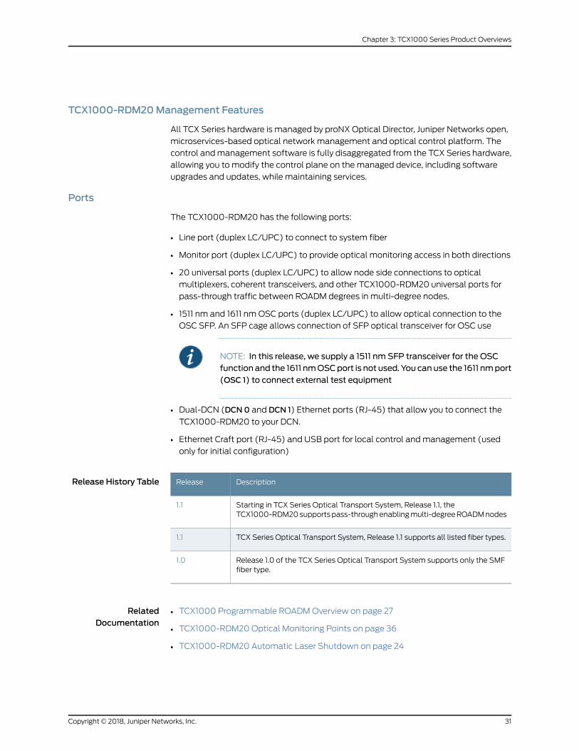
Ports
The TCX1000-RDM20 has the following ports:
• Line port (duplex LC/UPC) to connect to system fiber
• Monitor port (duplex LC/UPC) to provide optical monitoring access in both directions
• 20 universal ports (duplex LC/UPC) to allow node side connections to optical
multiplexers, coherent transceivers, and other TCX1000-RDM20 universal ports for
pass-through traffic between ROADM degrees in multi-degree nodes.
• 1511 nm and 1611 nmOSC ports (duplex LC/UPC) to allow optical connection to the
OSC SFP. An SFP cage allows connection of SFP optical transceiver for OSC use
NOTE: In this release, we supply a 1511 nm SFP transceiver for the OSCfunction and the 1611 nmOSCport is not used. You canuse the 1611 nmport(OSC 1) to connect external test equipment
• Dual-DCN (DCN0 and DCN 1) Ethernet ports (RJ-45) that allow you to connect the
TCX1000-RDM20 to your DCN.
• Ethernet Craft port (RJ-45) and USB port for local control andmanagement (used
only for initial configuration)
Release History Table DescriptionRelease
Starting in TCX Series Optical Transport System, Release 1.1, theTCX1000-RDM20supportspass-throughenablingmulti-degreeROADMnodes
1.1
TCX Series Optical Transport System, Release 1.1 supports all listed fiber types.1.1
Release 1.0 of the TCX Series Optical Transport System supports only the SMFfiber type.
1.0
RelatedDocumentation
TCX1000 Programmable ROADMOverview on page 27•
• TCX1000-RDM20 Optical Monitoring Points on page 36
• TCX1000-RDM20 Automatic Laser Shutdown on page 24
31Copyright © 2018, Juniper Networks, Inc.
Chapter 3: TCX1000 Series Product Overviews

TCX1000-2D8CMDColorless Multiplexer-Demultiplexer Overview
The TCX1000-2D8CMD is a simple and low cost port expander that uses a passive
combiner-splitter architecture. The TCX1000-2D8CMD is housed in industry standard
LGX cassettes that you can flexibly mount in 1RU, 3RU, or 4RU passive chassis solutions.
This section provides an overview of the TCX1000-2D8CMD and includes the following
subjects:
• TCX1000-2D8CMDOverview on page 32
• Client Ports on page 32
• Line Ports on page 32
• Operation on page 34
• TCX1000-2D8CMD Configurations on page 34
• TCX1000-2D8CMD Configuration Considerations on page 35
TCX1000-2D8CMDOverview
The TCX1000-2D8CMD is a colorless, two-directional optical multiplexer-demultiplexer
that provides eight colorless client ports and two line ports. You can use the
TCX1000-2D8CMD to expand the number of channels supported on the
TCX1000-RDM20, by connecting a line port from the TCX1000-2D8CMD to a single
universal port on the TCX1000-RDM20, you can add/drop an additional eight channels
to the TCX1000-RDM20. This allows for more transceivers to be connected to the
TCX1000-RDM20, while still maintaining the spectrally programmable (colorless)
operation and uses the minimum numbers of ports on the TCX1000-RDM20, allowing
for future expansion.
Client Ports
You connect your transceivers to the eight client ports on theTCX1000-2D8CMD labeled
Cx In and Cx Out.
NOTE: The passive combiner-splitter architecture of the TCX1000-2DCMDrequires youuseonly coherent transceivers. Channels received from the linesports are broadcast to all eight client ports. The connected coherenttransceiver is responsible for selecting its corresponding wavelength andfiltering out the impact of the unwanted broadcast channels. As such, theTCX1000-2D8CMD is suitable for coherent only applications.
Line Ports
The TCX1000-2D8CMD has two line ports. Channels present on the client ports are
combined and sent out both line ports simultaneously.
Copyright © 2018, Juniper Networks, Inc.32
TCX Series Optical Transport System Feature Guide

You can connect the line ports of the TCX1000-2D8CMD to the TCX1000-RDM20
universal ports to provide either single direction colorlessmultiplexing or 1 + 1 redundancy
protection.
Single Direction Add/Drop Colorless Multiplexing
Figure 1 on page 33 shows a single direction ROADM node that supports single direction
add/drop colorless multiplexing-demultiplexing. This example uses only one of the line
ports on the TCX1000-2D8CMD.
Looking at Figure 1 on page 33 from left to right: transceivers connect to the client (Cx In
andCxOut)portsof theTCX1000-2D8CMD,whose lineport (L0INandL0OUT) connects
to a single universal port on the TCX1000-RDM20.
All channels present on the TCX1000-2D8CMD are combined and sent out the line port
to the universal port on the TCX1000-RDM20, which multiplexes these channels and
sends them out the line port of the TCX1000-RDM20.
Figure 1: Single Direction Add/Drop Colorless Multiplexing
g200354
2D8CMD RDM20LineTransceivers
Line Port
Client Cx Ports
Client Cx Ports
Ux
1 + 1 Redundancy
Figure 2 on page 33 shows a 2-degree ROADM node that provides 1 + 1 redundancy for
the channels connected to the TCX1000-2D8CMD. The node consists of two
TCX1000-RDM20s and one TCX1000-2D8CMD. The software configuration of the
connectingTCX1000-RDM20scontrol theselectionofwhichchannelsare routed to/from
the ROADM line port.
Figure 2: Summary Colorless 1+1 Redundancy Multiplexing
g200355
LineLine
2D8CMD
RDM20RDM20
Transceivers
Client Cx PortsClient Cx Ports
Line PortLine Port
Ux Ux
33Copyright © 2018, Juniper Networks, Inc.
Chapter 3: TCX1000 Series Product Overviews

In this ROADM node, one of the line ports on the TCX1000-2D8CMD connects to
TCX1000-RDM20 serving the west direction (degree) and the other line port connects
to TCX1000-RDM20 serving the east degree. By connecting to both TCX1000-RDM20
devices, the TCX1000-2D8CMD has add/drop access to wavelengths on both degrees,
which is a prerequisite to setting up a service with redundant paths
NOTE: Because theTCX1000-2D8CMDusespassivecombiningandsplittingarchitecture, the identical composite line signal is sent out both line ports ofthe TCX1000-2D8CMD simultaneously and it is the responsibility of theconnected TCX1000-RDM20 to select which channels are sent through tothe TCX1000-RDM20 line port.
The drop (demultiplexing) side of the TCX1000-RDM20 is responsible forselecting which channels are sent to the receiving TCX1000-2D8CMD. TheTCX1000-RDM20 selects the channels and routes them to the appropriateTCX1000-2D8CMDlineport.TheTCX1000-2D8CMDbroadcasts the receivedchannels to all client ports where the connected transceiver is responsiblefor selecting the associated channel.
Operation
On the add (multiplexing) side, channels connected to the client input ports of the
TCX1000-2D8CMDaremultiplexed and broadcast out both line ports. The configuration
of the connected TCX1000-RDM20 controls which channels andmultiplexed by the
TCX1000-RDM20 and sent to its line port.
On the drop (demultiplexing) side, channels received on the TCX1000-RDM20 line ports
are demultiplexed by the associated TCX1000-RDM20 and routed to the appropriate
universal port, which is connected to the 2DCMD line port. The TCX1000-2D8CMD
broadcasts the channels to all client ports and the connected coherent transceiver is
responsible for selecting its corresponding wavelength and filtering out the impact of
theunwantedbroadcastchannels.Assuch, theTCX1000-2D8CMDissuitable forcoherent
only applications.
TCX1000-2D8CMDConfigurations
This section is meant to help you understand and determine the number of devices you
need for your particular configuration.
Example 1
For the first example, assume that you need to support 16 channels and you want to do
so using the fewest number of universal ports on the TCX1000-RDM20 so that you can
leave ports for future expansion. You can create this configuration using the
TCX1000-2D8CMD as follows:
• Two TCX1000-2D8CMD (8 ports x 2=16 ports)
• One TCX1000-RDM20
Copyright © 2018, Juniper Networks, Inc.34
TCX Series Optical Transport System Feature Guide

In this example, you connect the 16 transceivers to the client ports on the two
TCX1000-2D8CMDmultiplexers and you connect only one of the line ports from each
TCX1000-2D8CMD to a universal port on the TCX1000-RDM20. This leaves you 18
universal ports on the TCX1000-RDM20 for future expansion (20ports total - 2 ports=18
ports). This enables the transport of 16 colorless channels.
Example 2
For the second example, assume that you need to support 48 channels and youwant to
do so using the fewest number of universal ports on the TCX1000-RDM20 so that you
can leave ports for future expansion. You can create this configuration using the
TCX1000-2D8CMD as follows:
• Six TCX1000-2D8CMD (8 ports x 6 = 48 ports)
• One TCX1000-RDM20
The six TCX1000-2D8CMD elements provide a total of 48 ports for transceiver
connections. One of the line ports from each TCX1000-2D8CMD connects to a universal
port on the TCX1000-RDM20, using a total of 6 universal ports. This leaves you 14 free
universal ports on the TCX1000-RDM20 for future expansion.
TCX1000-2D8CMDConfiguration Considerations
NOTE: You cannot add/dropmultiple channels at the samewavelength tothe TCX1000-2D8CMD client ports. If two or more channels at the samewavelengthareaddedtotheTCX1000-2D8CMD,channelscancollidecausingtransmission impairment of the overlapping channels. The passive nature ofthe TCX1000-2D8CMD designmeans that there is no filtering in any of thepaths and if signals with overlapping spectral usage are presented to thesame2DCMD, interferenceoccursbetween thechannels. Youmust take careto ensure that these collisions do not happen as this cannot be enforced bythe hardware.
NOTE: Because theTCX1000-2D8CMDusespassivecombiningandsplittingarchitecture, the identical composite line signal is sent out both line portssimultaneouslyand it is the responsibilityof theconnectedTCX1000-RDM20to select which channels are sent through to the TCX1000-RDM20 line port.
The drop (demultiplexing) side of the TCX1000-RDM20 is responsible fordeterminingwhichpath is received.Bothpaths (frombothTCX1000-RDM20directions) cannot be operational at the same time because no switching isperformed in the TCX1000-2D8CMD.
RelatedDocumentation
TCX1000 Programmable ROADMOverview on page 27•
• Understanding TCX1000-RDM20 and TCX1000-2D8CMDMultiplexing Capabilities
on page 88
35Copyright © 2018, Juniper Networks, Inc.
Chapter 3: TCX1000 Series Product Overviews

• TCX1000-RDM20 Universal Port Rules on page 61
• Understanding Multi-Degree ROADMNodes on page 70
TCX1000-RDM20Optical Monitoring Points
The TCX1000-RDM20 contains a number of internal monitor points that provide
informationabout the totalopticalpowersandper-channelpowers (spectral information)
at different points within the system. You canmeasure performance at the following
ports:
• Line In and Line Out ports
You can also measure the total back-reflected power at the Line Out port.
• OSC0 In/OSC0Out andOSC 1 In/OSC 1 Out ports
Youcanalsoconnectexternal instrumentation, for exampleanoptical spectrumanalyzer
for spectral monitoring to the TCX1000-RDM20 to provide additional information at the
following monitor ports:
• Mon In—provides an optical monitor port after the pre-amplifier
• MonOut—provides an optical monitor port after the booster amplifier
In addition, in this release, the OSC 1 port is not used. As such, you can also connect an
optical time-domain reflectometer (OTDR) to thisport for characterizationof the system
fiber.
RelatedDocumentation
• TCX1000 Programmable ROADMOverview on page 27
• TCX1000-RDM20 Features on page 28
• TCX1000 Programmable ROADMHardware Guide
Copyright © 2018, Juniper Networks, Inc.36
TCX Series Optical Transport System Feature Guide

CHAPTER 4
Optical Control and ManagementOverview
• proNX Optical Director System and Optical Control Levels on page 37
• proNX Optical Director Overview on page 39
• proNX Optical Director Control and Management Software Components on page 40
proNXOptical Director System andOptical Control Levels
This topic provides an overview of the optical control andmanagement provided as part
of the proNX Optical Director software. It includes the following sections:
• Introduction on page 37
• System Controls on page 38
• Optical Control Levels on page 38
Introduction
All products in the TCX Series Optical Transport System portfolio are controlled and
managed by the proNXOptical Director. The proNXOptical Director is a highly-available
distributed software platform that runs on a three-node server cluster. It is an integral
component of the TCX1000 Series Optical Transport System and it is the combination
of theTCX1000Serieshardwareand theproNXOpticalDirector control andmanagement
software platform that provide the full TCX Optical Transport System solution.
The proNX Optical Director control andmanagement software abstracts the optical
control layer from the TCX1000Seriesmanaged device andmoves control of the optical
layer off of themanaged device to a centralized and programmable optical control layer
called the Juniper Programmable Photonic Layer. By disaggregating the optical control
plane from the TCX1000 Series hardware, you canmore regularly and flexibly modify
control planebehaviorwhilemaintaining service continuity, loweringoperational expense,
and fine-tuning transport-layer performance.
In traditional optical networks, theoptical control function resideson thedevicehardware
and the devices exchange proprietary control messages with each other on an optical
supervisory channel (OSC). This makes interworking across vendor equipment difficult
andoften leads to thedeploymentof single-sourcednetworks.Moving theoptical control
37Copyright © 2018, Juniper Networks, Inc.

layer toacentralized software controllermakesheterogeneousnetworkswithequipment
frommultiple vendors possible.
SystemControls
The proNXOptical Director control andmanagement software provides comprehensive
systems control functions that:
• Preventoreliminatedegradationofanypartof thesystem—TCX1000Seriesmanaged
devices constantly send streams of real-time optical linkmeasurements to the proNX
OpticalDirector,which thenuses thedata tobuild analways current viewof theoptical
links in the network. This allows the proNX Optical Director to make real-time control
decisions on all aspects of optical link management.
• Initiate immediate response to demands that are placed on the system—Asdemands
are placed on the system, the proNX Optical Director evaluates the information it
collects from themanaged devices, calculates corrective actions andmakes
configurationschanges to thedevice inorder tocompensate for the increaseddemands
on the system.
• Respond tochanges in the systemtomeet long term requirements, suchas continuous
control of equipment performance—TheproNXOptical Director continuously collects
information from themanaged devices in the network, evaluates that information and
automatically makes configurations changes that may be required to any of the
managed devices in the network.
Optical Control Levels
The proNXOptical Director control andmanagement software provides three additional
level of optical controls:
• Device Control — Responsible for maintaining the optical configuration of a device.
The proNX Optical Director receives streams of real-time optical link measurements
from the TCX1000Seriesmanaged device builds an always current view of the optical
links in the network. This allows the proNX Optical Director to make real-time control
decisions on all aspects of optical link management. The proNX Optical Director
discovers OLS network elements and reads and displays their configuration. You can
change theconfiguration, view theequipment inventory, pull upavisual representation
of the device, or view performancemonitoring parameters and alarm details.
• Span Loss Compensation — Responsible for controlling the optical path over a span
(between two sites). By abstracting the optical controls from the hardware, the proNX
OpticalDirector can readoptical power levels ondevicesatbothendsof a span, decide
whether changes need to bemade to the device configuration to compensate for span
loss and then send commands to the hardware tomake the appropriate adjustments.
• Nodal Loss Measurement— Responsible for calculating the nodal the loss in the
pass-through fiber connection between two TCX1000-RDM20s universal ports in a
multi-degree ROADM node and reporting out-of-range (OOR) alarms to the proNX
Optical Director. Nodal loss is the loss in power across the fiber between the two
universal ports that form the pass-through connection between two degrees in a
multi-degree ROADM node. The nodal loss is measured within the total optical power
Copyright © 2018, Juniper Networks, Inc.38
TCX Series Optical Transport System Feature Guide

over the pass-through fiber connection and is representedmathematically as the
difference between the transmitted dBm power on the UxOut port of one
TCX1000-RDM20 and the received dBm power on the Ux In port of the other
TCX1000-RDM20.
NOTE: This release of the TCXSeriesOptical Transport System calculatesnodal lossand reportsnodal lossout-of-rangealarmsbutdoesnot controlnodal loss. If the nodal loss calculation is notwithin range, Nodal lossOORalarms are raised at both ends of the pass-through fiber connection. If anodal loss OOR alarm occurs, inspect and very the pass-through fiberconnections.
• Network Control — Responsible for controlling the optical paths within an optical
network (endpoint-to-endpoint). The proNX Optical Director supports A-to-Z
provisioning and activation of optical services.
RelatedDocumentation
proNX Optical Director Overview on page 39•
• proNX Optical Director Control and Management Software Components on page 40
• proNX Optical Director Performance Monitors and Metrics on page 47
• About Juniper Optical Control Environment
proNXOptical Director Overview
The proNX Optical Director receives streams of real-time optical link measurements
from all the TCX1000 Series ROADM elements under management. From this data, the
proNX Optical Director builds an always current view of the optical links in the network.
This allows the proNXOptical Director tomake real-time control decisions on all aspects
of optical link management, including the following:
• Span loss compensation
• Nodal loss measurement and alarming
• Automatic per-channel power control through the entire network path
These control decisions are translated into commands that are communicated to the
TCX1000 Series managed devices for execution. This ongoing control loop allows the
proNX Optical Director to deliver optimal optical transmission performance for the
managed devices by dynamically and automatically controlling all aspects of optical
link output.
In traditional optical networks, this control function resideson thedevicehardwarewhere
the devices exchange proprietary control messages with each other on an optical
supervisory channel (OSC). Moving this function to a centralized software controller
makes heterogeneous networks with equipment frommultiple vendors possible.
39Copyright © 2018, Juniper Networks, Inc.
Chapter 4: Optical Control and Management Overview

The proNX Optical Director control andmanagement software provides A-to-Z
provisioning, dynamic real-time control of optical links, andactivation of optical services.
To create a channel service, you select the two service endpoints and the proNX Optical
Director automatically creates the optical path for the service.
The proNX Optical Director also enables fault, configuration, accounting, performance
and security (FCAPS) functionality and optical service activation on optical interfaces
residing in Juniper Networks routers and switches.
RelatedDocumentation
proNX Optical Director System and Optical Control Levels on page 37•
• proNX Optical Director Control and Management Software Components on page 40
proNXOptical Director Control andManagement Software Components
This topic describes the software components of the proNX Optical Director. It includes
the following subjects:
• proNX Optical Director Architecture and Software Components on page 40
• Orchestration Framework on page 41
• Web-Based User Interface on page 41
• Distributed Software Applications on page 42
proNXOptical Director Architecture and Software Components
Each optical product in the TCX Series Optical Transport System is disaggregated and
standalone. In addition, the proNX Optical Director control andmanagement software
disaggregates and abstracts the optical control layer from themanaged devices.
With the TCX Series Optical Transport System, the optical control intelligence resides
in the cloudwith the proNXOptical Director control andmanagement software enabling
you to simply control the optical transport layer.
Copyright © 2018, Juniper Networks, Inc.40
TCX Series Optical Transport System Feature Guide

Figure 3: proNXOptical Director Microservice Architecture
g200219
Juniper Networks Programmable Photonic Layer: TCX1000 Programmable ROADM, Amplifiers, andMultiplexers
Service and Network Orchestrators; BSS/OSS; Customer Self-Service Portal
REST; Open ROADM; JSON
NETCONFTelemetry
NETCONF, YANG, SNMP, XML, RPC NETCONF
YANG
TopologyExchange
REST; YANG
proNXOptical Director
ServiceActivation
andTopology
OpticalControlLoop
FCAPSWeb UserInterface
Third-PartyApps
Disaggregated Transponders IntegratedTransceivers Routers and Switches
NorthStar Controller
PathComputation
TopologyVisualization
Calendaringand
Scheduling
Real-TimeMonitoring
Analytics
Microservices
NOTE: The Northstar Controller functionality in Figure 3 on page 41 is notsupported in this release.
Juniper Programmable Photonic Layer
Figure 3 on page 41 illustrates the proNX Optical Director control andmanagement
software architecture. At the bottom of the stack is the Juniper Programmable Photonic
Layer, which represents the TCX Series device hardware layer and embedded firmware.
The optical control layer application in the proNXOptical Director controls andmanages
TCX Series device hardware, as well as compatible Juniper Networks disaggregated
transponders and integrated transceivers in routers and switches, by sending commands
to the managed devices over the device’s Netconf interface.
Orchestration Framework
The proNX Optical Director control andmanagement software is a Microservices Based
Architecture (MSA) platform. Microservices are implemented using Docker containers
and orchestration is provided by Kubernetes.
The infrastructure is responsible for the full lifecycle of the microservices including how
they are commissioned, upgraded, managed andmonitored, as well as how they are
removed during decommissioning. You can easily upgrade a single microservice within
the framework.The infrastructurealsosupportsplacement,healing, scalingand replication
of the microservices.
Web-Based User Interface
The proNX Optical Director control andmanagement software includes a web based
user interface fornetwork, device, andservicecontrol andmanagement.Theuser interface
contains views for all supported features including:
41Copyright © 2018, Juniper Networks, Inc.
Chapter 4: Optical Control and Management Overview

• Dashboard with Modular Dashlets
• Active and Historical Alarms
• Device Management, including Discovery, System Configuration, Provisioning,
Backup/Restore, and Software Upgrade
• Device Logs
• Service Activation and Display
• User Administration
• Tasks
Distributed Software Applications
The software applications included in the proNX Optical Director include:
• FCAPS Application on page 42
• Service Activation and Topology Application on page 42
• Optical Control Layer Application on page 43
FCAPS Application
TheFCAPSapplicationenables fault, configuration, accounting,performance,andsecurity
(FCAPS) functionality for theTCX1000Seriesmanageddevices, aswell as for compatible
Juniper Networks routers and switches. FCAPS support on these devices includes:
• Device Discovery, Undiscovery
• Inventory
• Configuration and Provisioning
• Backup and Restore
• PM Collection and Historical binning
• Log Collection
• Software upgrade
• Alarm and Historical Alarms
Service Activation and Topology Application
Anoptical serviceprovideschannel connectivitybetweenserviceendpointsand isdefined
by its wavelength and the endpoints that it interconnects. The proNX Optical Director
service management across the optical network includes: service provisioning, service
activation, and service monitoring and troubleshooting. The proNX Optical Director
supportsA-to-Zprovisioningandactivationofoptical services. Youselect the twoservice
endpoints and the proNX Optical Director automatically configures the optical path
between the two service endpoints.
Copyright © 2018, Juniper Networks, Inc.42
TCX Series Optical Transport System Feature Guide
The proNXOptical Director learns and displays the topology of the network and provides
various visual indicators that allow you to see the health of the network at a glance and
deal with problem areas in a proactive manner.
Optical Control Layer Application
Theoptical control layer (OCL) application provides dynamic real-time control of optical
links, provides A-to-Z provisioning and activation of optical services, and provides
performancecontrolandmonitoring forautomaticspan losscompensationandautomatic
channel power control. The TCX1000 Series elements constantly send streams of
real-time optical link measurements to the proNX Optical Director, which then uses the
data to build an always current view of the optical links and services in the network. This
allows the proNX Optical Director to make real-time control decisions on all aspects of
optical link and service management.
The OCL application is a conglomerate of real-time control algorithms, which
automatically configure TCX Series optical devices to provide optimal optical network
transmission performance. Near-instant network-wide visibility of the services provided
by the disaggregated infrastructure allows implementation of advanced control
algorithms, which optimize the optical transmission for the whole service path or even
a complete network.
The other functions of the OCL application include:
• Generating control-related performancemonitors and alarms
• Zero-lambda turnup
• Short span support
RelatedDocumentation
• proNXOptical Director User Guide
• proNX Optical Director System and Optical Control Levels on page 37
• proNX Optical Director Overview on page 39
• proNX Optical Director Performance Monitors and Metrics on page 47
• proNX Optical Director Alarms on page 114
43Copyright © 2018, Juniper Networks, Inc.
Chapter 4: Optical Control and Management Overview

Copyright © 2018, Juniper Networks, Inc.44
TCX Series Optical Transport System Feature Guide
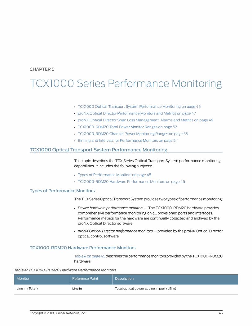
CHAPTER 5
TCX1000 Series Performance Monitoring
• TCX1000 Optical Transport System Performance Monitoring on page 45
• proNX Optical Director Performance Monitors and Metrics on page 47
• proNX Optical Director Span Loss Management, Alarms and Metrics on page 49
• TCX1000-RDM20 Total Power Monitor Ranges on page 52
• TCX1000-RDM20 Channel Power Monitoring Ranges on page 53
• Binning and Intervals for Performance Monitors on page 54
TCX1000Optical Transport SystemPerformanceMonitoring
This topic describes the TCX Series Optical Transport System performancemonitoring
capabilities. It includes the following subjects:
• Types of Performance Monitors on page 45
• TCX1000-RDM20 Hardware Performance Monitors on page 45
Types of PerformanceMonitors
TheTCXSeriesOptical TransportSystemprovides two typesofperformancemonitoring:
• Device hardware performance monitors—The TCX1000-RDM20 hardware provides
comprehensive performancemonitoring on all provisioned ports and interfaces.
Performancemetrics for the hardware are continually collected and archived by the
proNX Optical Director software.
• proNXOptical Director performancemonitors—provided by the proNXOptical Director
optical control software
TCX1000-RDM20Hardware PerformanceMonitors
Table4onpage45describes theperformancemonitorsprovidedby theTCX1000-RDM20
hardware.
Table 4: TCX1000-RDM20 Hardware PerformanceMonitors
DescriptionReference PointMonitor
Total optical power at Line In port (dBm)Line InLine In (Total)
45Copyright © 2018, Juniper Networks, Inc.

Table 4: TCX1000-RDM20 Hardware PerformanceMonitors (continued)
DescriptionReference PointMonitor
Total signal power at Line In port (dBm)Line InLine In OMS
OSC 0 (1511 nm) power at Line In port (dBm)Line InLine In OSC 0
OSC 1 (1611 nm) power at Line In port (dBm)Line InLine In OSC 1
Channel power at Line In port (dBm)Line InLine In Och
Total optical power at Line Out port (dBm)Line OutLine Out (Total)
Total signal power at Line Out port (dBm)Line OutLine Out OMS
OSC 0 (1511 nm) power at Line Out port (dBm)Line OutLine Out OSC 0
OSC 1 (1611 nm) power at Line Out port (dBm)Line OutLine Out OSC 1
Total signal power reflected back into Line Out port (dBm)Line OutLine Out BR
Ratio of "Line Out OMS" over "Line Out BR" (dB)Line OutLine Out Optical Return Loss
Channel power at Line Out port, not including attenuation from Line Out VOA(dBm)
Line OutLine Out Och
OSC 0 (1511 nm) power at OSC 0 In port (dBm)OSC0 InOSC 0 In
OSC 0 (1511 nm) power at OSC 0 Out port (dBm)OSC0OutOSC 0Out
OSC 1 (1611 nm) power at OSC 1 In port (dBm)OSC 1 InOSC 1 In
OSC 1 (1611 nm) power at OSC 1 Out port (dBm)OSC 1 OutOSC 1 Out
Total signal power at Ux In port, x=0 to 19 (dBm)Ux InUx In
Channel power at Ux In port, x=0 to 19 (dBm)Ux InUx In
Total signal power at Ux Out port, x=0 to 19 (dBm)UxOutUx Out
Channel power at Ux Out port, x=0 to 19 (dBm)UxOutUx Out
Chassis temperature (degrees C)N/AChassis Temperature
Power supply 0 input voltage (V)PSU inputPSU 0 Voltage
Power supply 0 input current (A)PSU inputPSU 0 Current
Power supply 1 input voltage (V)PSU inputPSU 1 Voltage
Copyright © 2018, Juniper Networks, Inc.46
TCX Series Optical Transport System Feature Guide

Table 4: TCX1000-RDM20 Hardware PerformanceMonitors (continued)
DescriptionReference PointMonitor
Power supply 1 input current (A)PSU inputPSU 1 Current
Fanmodule 0, fan unit x speed, x=1 to 3 (rpm)N/AFan Module 0, fan x speed
Fanmodule 1, fan unit x speed, x=1 to 3 (rpm)N/AFan Module 1, fan x speed
RelatedDocumentation
Binning and Intervals for Performance Monitors on page 54•
• TCX1000 Programmable ROADMOverview on page 27
• proNX Optical Director Performance Monitors and Metrics on page 47
proNXOptical Director PerformanceMonitors andMetrics
This topic provides an overview of the performancemanagement and control provided
by the proNX Optical Director software. It includes the following topics:
• proNX Optical Director Performance Management and Control on page 47
• proNX Optical Director Performance Monitors on page 47
proNXOptical Director PerformanceManagement and Control
The proNX Optical Director control andmanagement software provides A-to-Z
provisioning, dynamic real-time control of optical links, andactivation of optical services.
The proNX Optical Director software also monitors the performance of the
TCX1000-RDM20 hardware to provide certain control functions, for example, span loss
management.
In traditional optical networks, these control functions reside on themanaged device
itself and thenodesexchangeproprietarycontrolmessageswitheachotheronanoptical
supervisory channel (OSC). This makes interworking across vendor equipment difficult
and often leads to the deployment of single-sourced networks. Moving this function to
a centralized software controller makes heterogeneous networks with equipment from
multiple vendors possible.
proNXOptical Director PerformanceMonitors
The proNX Optical Director control andmanagement software provides the following
performancemonitors:
Span LossManagement
StartingwithTCXSeriesOpticalTransportSystem,Release 1.0, theproNXOpticalDirector
supports span loss management. The proNX Optical Director provides span control on
the TCX1000-RDM20, which determines the total optical loss of the span andmakes
automatic adjustments to the device hardware controls to compensate for the loss.
47Copyright © 2018, Juniper Networks, Inc.
Chapter 5: TCX1000 Series Performance Monitoring

Channel Automatic Power Management
StartingwithTCXSeriesOptical TransportSystem,Release 1.1, theproNXOpticalDirector
supports Channel Automatic Power Management. The proNX Optical Director provides
channel automatic power management to compensate for individual channel power
variations tomaintain theoptimalperformanceof thechannel through theentire network
path and to ramp-up channels to the correct line operating power, maintain that power
withinpredefined tolerance levels throughoutoperationandprovidegraceful ramp-down
of the channel during decommissioning.
Nodal LossMeasurement
Starting with TCX Series Optical Transport System, Release 1.1, the TCX1000-RDM20
reports nodal loss measurements to the proNX Optical Director. Nodal loss is the loss in
the fiber between the two TCX1000-RDM20s at a pass-through site, in other words the
loss in the fiber between the two universal ports being used for pass-through.
The proNX Optical Director provides a nodal loss metric described Table 5 on page 48.
Table 5: Nodal Loss PerformanceMetric
BinningFieldsRefresh rateUnit(dB)Entity
PerformanceMetric
1-minute
15-minute
24-hr
Current,Minimum,Maximum,Average
Every time client data arrivesfromoneof themanageddeviceend-pointsofa fiber-connection(pass-through Ux port
dBTx and Rx Client sidefiber connect
Nodal Loss
Release History Table DescriptionRelease
Starting with TCX Series Optical Transport System, Release 1.1, the proNXOpticalDirector supports Channel Automatic Power Management.
1.1
Starting with TCX Series Optical Transport System, Release 1.1, theTCX1000-RDM20 reportsnodal lossmeasurements to theproNXOpticalDirector.
1.1
Startingwith TCXSeriesOptical Transport System, Release 1.0, the proNXOpticalDirector supports span loss management.
1.0
RelatedDocumentation
proNX Optical Director Span Loss Management, Alarms and Metrics on page 49•
• proNX Optical Director System and Optical Control Levels on page 37
• proNX Optical Director Control and Management Software Components on page 40
• About Juniper Optical Control Environment
Copyright © 2018, Juniper Networks, Inc.48
TCX Series Optical Transport System Feature Guide

proNXOptical Director Span LossManagement, Alarms andMetrics
The proNXOptical Director provides span lossmanagement, which determines the total
optical loss of the span andmakes adjustment to the device hardware controls to
compensate for the loss. This topic describes the span loss management capability
provided by the proNX Optical Director on TCX1000 Series devices. It includes the
following sections:
• What is Span Loss on page 49
• Span Loss Alarms on page 49
• Span Loss Performance Metrics on page 51
What is Span Loss
Span loss can be defined as the total system attenuation between line ports of adjacent
TCX1000Series devices in thenetwork. This includes the loss from the transmission fiber
and any additional losses from optical connections within the path. An example of
additional losses is the attenuation introduced when optical patch panels are used to
manage cabling within an installation.
The proNX Optical Director measures the span loss by reading the output power (dBm)
at the Line Out port at one end of the fiber and the input power (dBm) at Line In port at
the other end of the fiber. These measurements are continuously read at both ends of
the span and reported to the proNX Optical Director. After proNX Optical Director reads
these power levels, it calculates the span loss and adjusts internal set points on one or
both TCX1000 Series devices to compensate for the loss while minimizing the added
noise. For example, based on themeasured span loss, the proNX Optical Director may
determine that the input level on the downstream device is too low. In this case, proNX
Optical Director adjusts the output level on the LineOut port of the local TCX1000Series
device to compensate for the span loss.
Short Span Support
On short spans, if themeasured span loss is such that themaximum input powers to the
downstream TCX1000 Series device may be exceeded, the span control feature adjusts
the launch power at the upstream site to automatically compensate. In this way, the
span control seamlessly manages span losses as low as 0 dB.
Span Control Over Time
The span control continuously monitors the span loss between the line ports of the
TCX1000-RDM20andadjusts the internal set points to compensate for thiswhile adding
the minimum amount of noise. In this way the span control automatically adjusts for
variations in span loss over time, for example, from seasonal variations in loss or for
additional losses added after a cable repair.
Span Loss Alarms
When a span is first brought into service, the span control configures the internal
components of the TCX1000Series devices to be optimized for that loss. In cases of very
49Copyright © 2018, Juniper Networks, Inc.
Chapter 5: TCX1000 Series Performance Monitoring

large changes in span loss, the optimization cannot bemaintained over the full operating
specification of the managed device with full optical performance. The proNX Optical
Director provides a Span Loss Out-Of-Range (OOR) alarm, which indicates that either
the TCX1000 Series device is being operated outside of specification or that the internal
configuration is no longer optimized.
If themeasured span loss is outside the allowable range for themanaged device, a Span
LossOut-Of-Range (OOR) alarm is raised and logged by the proNXOptical Director. The
automatic span control functionality of the TCX1000-RDM20 ensures that the OOR
alarm is unlikely to be raised except in the rare event that the span loss changes by a very
large amount after initial commissioning.
For example, let us assume that we have two TCX1000 Series devices connected
point-to-point. The local device is “device A” and the remote device is “device B. The
proNX Optical director reads the output dBm power level at the device A transmit port
(Line Out) and the dBm power level received at the device B Line In port. If, after
subtracting the receive line power measured at device B from the transmit line power
measured at device A, the resulting value is not within the allowable range, two alarms
are raised in proNX Optical Director:
• Tx Span Loss Out-Of-Range — This alarm is raised at the transmit end Line Out port
on device A.
• Rx Span Loss Out-of-Range — This alarm is raised at the receive end Line In port on
device B.
In the rare event that the OOR alarm is raised, you can remotely re-optimize the span by
toggling the administrative state of the line port by setting the administrative state to
Out-of-Service and then back to In-Service.
NOTE: This is traffic impacting and so is not automated. Normal controlbehavior ensures that internal configuration re-optimization is not required,however, in rare cases suchas very large changes in span loss, thismayoccur.
If the reported span loss is outside of the TCX1000-RDM20 specification, the optical
connections in the span should be verified to identify why the accumulated losses are
now out of range.
Table 6 on page 51 describes the supported span loss ranges for the TCX1000-RDM20.
Copyright © 2018, Juniper Networks, Inc.50
TCX Series Optical Transport System Feature Guide
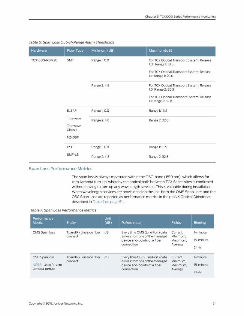
Table 6: Span Loss Out-of-Range Alarm Thresholds
Maximum(dB)Minimum (dB)Fiber TypeHardware
For TCX Optical Transport System, Release1.0: Range 1: 18.5
For TCX Optical Transport System, Release1.1: Range 1: 20.0
Range 1: 0.0SMFTCX1000-RDM20
For TCX Optical Transport System, Release1.0 Range 2: 30.3
For TCX Optical Transport System, Release1.1 Range 2: 32.8
Range 2: 4.8
Range 1: 16.5Range 1: 0.0ELEAF
Truewave
TruewaveClassic
NZ-DSF
Range 2: 32.8Range 2: 4.8
Range 1: 13.5Range 1: 0.0DSF
SMF-LSRange 2: 32.8Range 2: 4.8
Span Loss PerformanceMetrics
The span loss is always measured within the OSC-band (1510 nm), which allows for
zero-lambda turn-up, whereby the optical path between TCX Series sites is confirmed
without having to turn up any wavelength services. This is valuable during installation.
When wavelength services are provisioned on the link, both the OMS Span Loss and the
OSC Span Loss are reported as performancemetrics in the proNX Optical Director as
described in Table 7 on page 51.
Table 7: Span Loss PerformanceMetrics
BinningFieldsRefresh rateUnit(dB)Entity
PerformanceMetric
1-minute
15-minute
24-hr
Current,Minimum,Maximum,Average
Every timeOMS(LinePort)dataarrives fromoneof themanageddevice end-points of a fiberconnection
dBTxandRxLine side fiberconnect
OMS Span loss
1-minute
15-minute
24-hr
Current,Minimum,Maximum,Average
Every timeOSC(LinePort)dataarrives fromoneof themanageddevice end-points of a fiberconnection
dBTxandRxLine side fiberconnect
OSC Span loss
NOTE: Usedforzerolambda turnup.
51Copyright © 2018, Juniper Networks, Inc.
Chapter 5: TCX1000 Series Performance Monitoring

Release History Table DescriptionRelease
For TCX Optical Transport System, Release 1.1:1.1
For TCX Optical Transport System, Release 1.11.1
For TCX Optical Transport System, Release 1.0:1.0
For TCX Optical Transport System, Release 1.01.0
RelatedDocumentation
proNX Optical Director Alarms on page 114•
TCX1000-RDM20 Total Power Monitor Ranges
This topicdescribes thepower ranges for total powermonitoring. It includes the following:
• Power Ranges for Power Monitors on page 52
Power Ranges for Power Monitors
Two power ranges are defined for each power monitor:
• Operation — The operation range is the optical power range over which the channel
monitoring and control is expected to meet all operating performance requirements.
• Alarm— The alarm range is the optical power range over which the monitoring is still
required in order to have proper system alarming and fault detection. The alarm range
maximum andminimum define the hardware limits (power readings outside of
hardware limits are considered invalid).
Table 8 on page 52 describes the total power monitoring range for the universal ports.
Table 8: Universal Port Optical Power Monitor Ranges
Operation Range (dBm)Alarm Range (dBm)
Reference PointMonitor Name MaxMinMaxMin
23-22.424-29Ux InUx In
20.5-2322.7-36.5UxOutUx Out
Table 9 on page 53 lists the preamplifier optical power monitoring ranges.
Copyright © 2018, Juniper Networks, Inc.52
TCX Series Optical Transport System Feature Guide

Table 9: Preamplifier Optical Power Monitoring Ranges
Operation Range (dBm)Alarm Range (dBm)
Reference PointMonitor Name MaximumMinimumMaximumMinimum
13.2-3313.6-38Line InLine In
2.5-43.911.6-48.5Line InOSC 0 Line In
2.5-43.911.6-48.5Line InOSC 1 Line In
3-4213.5-48OSC 0 OutOSC 0 Out
3-4213.5-48OSC 1 OutOSC 1 Out
Table 10 on page 53 lists the booster power monitoring ranges.
Table 10: Booster Optical Power Monitoring Ranges
NotesOperation Range (dBm)Alarm Range (dBm)
Reference PointMonitor Name MaxMinMaxMin
C-Band poweronly
22.9-326.8-8.2Line Out
(VOAset to0dB)
Line Out
C-Band poweronly
22.9-1825.2-24.4Line OutLine Out
OSC 0 power only9.5-11.911.6-47.5Line OutOSC 0 Line Out
OSC 1 power only9.5-12.411.1-47.5Line OutOSC 1 Line Out
OSC 0 power only10-1013.5-47OSC 1 InOSC 0 In
OSC 1 power only10-1013.5-47OSC 2 InOSC 1 In
RelatedDocumentation
TCX1000 Optical Transport System Performance Monitoring on page 45•
• Binning and Intervals for Performance Monitors on page 54
TCX1000-RDM20 Channel Power Monitoring Ranges
This topic describes the channel power monitoring ranges for the TCX1000-RDM20
Two power ranges are defined for eachmonitor:
• Operation — The Operation range is the optical power range over which the channel
monitoring and control is expected to meet all operating performance requirements.
53Copyright © 2018, Juniper Networks, Inc.
Chapter 5: TCX1000 Series Performance Monitoring

• Alarm— The Alarm range is the optical power range over which the monitoring is still
required in order to have proper system alarming and fault detection. The alarm range
maximum andminimum define the hardware limits (power readings outside of
hardware limits are considered invalid).
Table 11 on page 54 describes the channel power monitoring ranges.
Table 11: Channel Power Monitoring Ranges
Operation Range (dBm)Alarm Range (dBm)
Monitor Name MaxMinMaxMin
-3-32.2-3-35.4Line In
0.3-23.60.3-28.1U x In
RelatedDocumentation
TCX1000 Optical Transport System Performance Monitoring on page 45•
• TCX1000-RDM20 Total Power Monitor Ranges on page 52
• Binning and Intervals for Performance Monitors on page 54
Binning and Intervals for PerformanceMonitors
Performancemonitoring support for TCX1000 Series managed devices follows typical
performancemonitor conventions, including collecting data at 15-minute and 24-hour
intervals, and supporting current and historical data.
TCX1000 Series devices retain the following historical bins:
• 15 x 1-minute historical bins
• 96 x 15-minute historical bins
• 7 x 1-day historical bins
Four current performancemonitor intervals are supported:
• 1 day
• 15 minutes
• 1 minute
• unTimed
The unTimed bin accumulates counts from the time performancemonitoring on the
module starts. The unTimed bin does not roll over into a historical bin.
TCX1000 devices support three historical PM intervals:
• 1 day
Copyright © 2018, Juniper Networks, Inc.54
TCX Series Optical Transport System Feature Guide

• 15 minutes
• 1 minute
You initiate the collection of performancemetrics manually in proNX Optical Director,
which then requests the metrics from the device. Once the task is complete you can go
back to view themetrics on the desired port.
RelatedDocumentation
• TCX1000 Optical Transport System Performance Monitoring on page 45
• TCX1000 Programmable ROADMOverview on page 27
• TCX1000-RDM20 Features on page 28
55Copyright © 2018, Juniper Networks, Inc.
Chapter 5: TCX1000 Series Performance Monitoring

Copyright © 2018, Juniper Networks, Inc.56
TCX Series Optical Transport System Feature Guide

CHAPTER 6
Product Applications, Port Rules andJuniper Networks Compatible Products
• TCX1000 Series Product Applications on page 57
• Juniper Networks Compatible Routers, Switches, Optical Multiplexers and
Transponders on page 60
• TCX1000-RDM20 Universal Port Rules on page 61
• TCX Series Optical Transport System Capacities on page 63
TCX1000 Series Product Applications
This topic provides anoverviewof theTCX1000Series product applications and includes
the following topics:
• TCX1000-RDM20 Product Applications on page 57
TCX1000-RDM20 Product Applications
The TCX1000-RDM20 is a highly flexible and open DWDM optical line system that
provides reconfigurable optical add/dropmultiplexing and pass-through of channels in
amulti-degree node. The TCX1000-RDM20 enablesmulti-terabit wavelength switching
capabilities to compliment the high capacity routing, switching and transport interfaces
on Juniper Networks routing and switching platforms. The TCX1000-RDM20 is primarily
for data center interconnect (DCI), access and aggregation, andmetropolitan-area
networks and can also be used in the core.
Figure 4 on page 58 shows an example of how youmight pair the TCX1000-RDM20with
your existing Juniper Networks routers and switches as well as our BTI7800 Series
products to build an ultra, high capacity packet-optical network.
Transceivers integrated in the JuniperNetworks routersandswitchescanconnectdirectly
to the universal ports on the TCX1000-RDM20 or can connect through an optical
multiplexer such as the TCX1000-2D8CMD or BTI7800-FMD96, enabling you to route
high-speed services over the optical network. The proNX Optical Director controls and
manages the optical layer from the transceiver endpoints in the routers and switches all
the way through your optical network.
57Copyright © 2018, Juniper Networks, Inc.

Figure 4: TCX1000-RDM20Overview
g200053
Integrated OpticalInterfaces
and DisaggregatedOptical Products
Integrated OpticalInterfaces
and DisaggregatedOptical Products
BTI Series
PTX Series
MX Series
QFX Series BTI Series
PTX Series
MX Series
QFX Series
Northstar SDNController
proNXOptical Director
ROADM, Mux/Demux, ILA, TxpManagement
TCX1000-RDM20
n x 100G/200GCoherent Channels
ILA TCX1000-RDM20
Regardless of your application, you canmix coherent services on the TCX1000-RDM20.
For example, you can connect 100 Gbps services from anMX Series router, as well as
connect200Gbpsservices runningonaQFXSeries switch to thesameTCX1000-RDM20.
In the TCX Series Optical Transport System, Release 1.0, the TCX1000-RDM20 supports
only single span, point-to-point links. The TCX1000-RDM20 supports up to 96 x 200
Gbps coherent channels at 50 GHz spacing in a point-to-point link configuration by
leveraging the BTI7800-FMD96. The TCX1000-RDM20 supports an extended C-band
spectrum from 191.325 to 196.125 THz (1528.578 to 1566.928 nm) which is consistent
with96channel operation (196.1 to 191.35THzchannel centers) ona50GHz ITUchannel
grid.
Starting in TCX Series Optical Transport System, Release 1.1, the TCX1000-RDM20
supports single span, point-to-point link topologies, as well as ring, mesh, and linear
multi-hop ROADM services.
Data Center Applications
For data center interconnection (DCI) applications, you can pair the TCX1000-RDM20
with the following Juniper Networks routers and switches for a complete end-to-end
solution:
• For Juniper Networks QFX10008 and QFX100016 Ethernet switches using the
QFX10K-12C-DWDM line card (6 x 200 Gbps DWDM), the TCX1000-RDM20 enables
an end-to-end solution with up to 19.2 Tbps per fiber.
• For Juniper Networks MX Series 3D Universal Edge Routers including the
MX240/MX480/MX960/MX2010/MX2020, using the MIC3-100G-DWDM interface
card, the TCX1000-RDM20 enables an end-to-end solution with up to 9.6 Tbps per
fiber.
For MX Series routers, you can also use the MIC6-100G-CFP2, which is a 100-Gigabit
Ethernet MIC with CFP2 ports.
Copyright © 2018, Juniper Networks, Inc.58
TCX Series Optical Transport System Feature Guide

• For Juniper Networks PTX3000 and PTX5000 routers using the PTX-5-100G-WDM
physical interface card (PIC), the TCX1000-RDM20 enables an end-to-end solution
with up to 9.6 Tbps per fiber.
For PTX Series routers, you can also use the P2-100GE-OTN, which is a 100-Gigabit
EthernetOTNPICwithCFP2. Fourports that canbeconfiguredas 100-Gigabit Ethernet,
100-Gigabit OTN, or a combination of 100-Gigabit Ethernet and 100-Gigabit Ethernet
OTN interfaces.
Access, Aggregation, andMetro Applications
For access, aggregation, andmetro applications, you can pair the TCX1000-RDM20with
the following Juniper Networks routers and switches for a complete end-to-end solution:
• For Juniper Networks MX Series 3D Universal Edge Routers including the
MX240/MX480/MX960/MX2010/MX2020, using the using the MIC3-100G-DWDM
interface card, the TCX1000-RDM20 enables an end-to-end solution with up to 9.6
Tbps per fiber.
For MX Series routers, you can also use the MIC6-100G-CFP2, which is a 100-Gigabit
Ethernet MIC with CFP2 ports.
Release History Table DescriptionRelease
Starting inTCXSeriesOpticalTransportSystem,Release 1.1, theTCX1000-RDM20supports single span, point-to-point link topologies, as well as ring, mesh, andlinear multi-hop ROADM services.
1.1
In the TCX Series Optical Transport System, Release 1.0, the TCX1000-RDM20supports only single span, point-to-point links
1.0
RelatedDocumentation
TCX1000-RDM20 Universal Port Rules on page 61•
• Understanding TCX Series Point-to-Point Topologies on page 65
• TCX Series Optical Transport System Capacities on page 63
• TCX1000 Programmable ROADMOverview on page 27
59Copyright © 2018, Juniper Networks, Inc.
Chapter 6: Product Applications, Port Rules and Juniper Networks Compatible Products

JuniperNetworksCompatibleRouters,Switches,OpticalMultiplexersandTransponders
Table 12 on page 60 lists the Juniper Networks routers and switches and the associated
optical interfaces that are compatible with the TCX1000-RDM20 and proNX Optical
Director.
Table 13 on page 61 lists the Juniper Networks optical multiplexers and transponders
that are compatible with the TCX1000-RDM20 and proNX Optical Director.
Table 12: TCX1000-RDM20 Compatible Devices
TCX1000-RDM20 Enabled SolutionSupported InterfacesJuniper Networks Device
Enables an end-to-end solution with up to9.6 Tbps per fiber for:
• Data Center Interconnection (DCI)applications
• Access, Aggregation, and Metroapplications
MIC3-100G-DWDM—100-Gigabit DWDMOTNMIC supported on both the MPC3E(MX-MPC3E-3D) and MPC3E NG(MPC3E-3D-NG). The MIC3-100G-DWDMMIC provides a single 100-Gigabit Ethernetinterfaceport that supportsDP-QPSKwithcoherent reception and OTU4 and OTU4(v) framingmodes.
See 100-Gigabit DWDMOTNMICwithCFP2-ACO
MX Series 3D Universal EdgeRouters including:
• MX240
• MX480
• MX960
• MX2010
• MX2020
MIC6-100G-CFP2, a 100-Gigabit EthernetMIC with CFP2 ports. Supports two100-Gigabit Ethernet CFP2 ports.
100-Gigabit Ethernet MIC with CFP2
Enablesanend-to-endDCI solutionwithupto 9.6 Tbps per fiber.
PTX-5-100G-WDM— 5-port 100-GigabitDWDMOTNPICforboth thePTX3000andthe PTX5000 routers.
The PTX-5-100G-WDM PIC provides five100-Gigabit Ethernet interface ports thatsupportdual-polarizationquadraturephaseshift keying (DP-QPSK)modulation withcoherent reception and OTU4 and OTU4(v) framingmodes.
See, 100-Gigabit DWDMOTN PIC withCFP2-ACO (PTX Series)
PTX Series Packet TransportRouters including:
• PTX3000
• PTX5000
P2-100GE-OTN, a 100-Gigabit EthernetOTN PICwith CFP2. Four ports that can beconfigured as 100-Gigabit Ethernet,100-Gigabit OTN, or a combination of100-Gigabit Ethernet and 100-GigabitEthernet OTN interfaces.
100-Gigabit Ethernet OTN PIC withCFP2
Copyright © 2018, Juniper Networks, Inc.60
TCX Series Optical Transport System Feature Guide

Table 12: TCX1000-RDM20 Compatible Devices (continued)
TCX1000-RDM20 Enabled SolutionSupported InterfacesJuniper Networks Device
Enablesanend-to-endDCI solutionwithupto 19.2 Tbps per fiber using 200 Gbpscoherent channels.
QFX10K-12C-DWDM line card: 6-port linecard, with built-in optics, supports flexiblerate modulation at 100 Gbps, 150 Gbps,and 200Gbps speeds and is supported onboth QFX10008 and QFX100016.
See,QFX10K-12C-DWDMCoherentLineCard
QFX10000lineofmodularEthernetswitches including:
• QFX10008
• QFX100016
Table 13 on page 61 lists the Juniper Networks compatible optical multiplexers and
transponders.
Table 13: Juniper Networks Compatible Optical Multiplexers and Transponders
How to Use It With the TCX1000-RDM20Juniper Networks Device
The TCX1000-2D8CMD colorless multiplexer can be used toadd/dropanadditional8channels to theTCX1000-RDM20anduses only a single universal port on the TCX1000-RDM20. TheTCX1000-2D8CMD enables both single andmulti-directionadd/dropmultiplexing, depending on how it is connected to theTCX1000-RDM20.
NOTE: TheTCX1000-2D8CMD is for coherentapplicationsonly.
TCX1000-2D8CMD
The BTI7800-FMD96 opticalmultiplexer-demultiplexer can beused to add/drop 96 channels to the TCX1000-RDM20 byconnecting the common/line port of the BTI7800-FMD96 to asingle universal port. This configuration supports up to96 x 200Gbps coherent channels with 50 GHz fixed channel spacing.
BTI7800-FMD96
See, BTI7800 Packet Optical Transport Platform
The BTI78000 Universal Forwarding Modules (UFM) can beused for a disaggregated transponder solution including theBTI7800 UFM3with coherent CFP and the BTI7800 UFM6.
NOTE: This release of the proNX Optical Director does notsupport control andmanagement of these devices.
BTI7800Universal ForwardingModules (UFM) transponders
See, BTI7800 Packet Optical Transport Platform
RelatedDocumentation
proNX Optical Director Topology Support•
• TCX1000-RDM20 Links and Services Overview on page 100
TCX1000-RDM20Universal Port Rules
In this release, you can use the universal ports on the TCX1000-RDM20 as follows:
1. Each and any universal port can be directly connected to a coherent transceiver.
coherent transceivers can be:
• Compatible integrated transceivers in a Juniper Networks router or switch
61Copyright © 2018, Juniper Networks, Inc.
Chapter 6: Product Applications, Port Rules and Juniper Networks Compatible Products

• Juniper Networks disaggregated transceiver such as the BTI7800 Universal
Forwarding Modules: UFM3 with coherent CFP and UFM6
NOTE: This release of the proNXOptical Director does not supportcontrol andmanagement of UFM3 and UFM6 transponders.
• Third-party transceiver
TheTCX1000-RDM20supportsup to20colorlesschannel connections—anychannel
can be added on any universal port of the TCX1000-RDM20. This is enabled in
conjunction with tunable transceivers.
2. Eachandanyuniversalport canbeconnected toanopticalmultiplexer-demultiplexer.
This enables you to plan for future expansion. By connecting an external optical
multiplexer, youcanuse the fewestnumberofuniversalportson theTCX1000-RDM20.
For example, connecting one of the TCX1000-2D8CMD line ports to a single universal
port on the TCX1000-RDM20 enables you to switch 8 additional colorless channels
on the TCX1000-RDM20 and you still have a 19 universal ports available for direct
add/drop traffic, pass-through connections, or for additional optical
multiplexers-demultiplexers. The TCX1000-2D8CMD supports colorless single and
multi-direction add/drop capability.
The BTI7800-FMD96 fixed opticalmultiplexer-demultiplexer is also compatible with
the TCX1000-RDM20. You can connect the line port of the BTI7800-FMD96 optical
multiplexer to a universal port on the TCX1000-RDM20 enabling you to support up
to 96 x 200 Gbps coherent channels at 50 GHz spacing on a single universal port.
NOTE: Ports on the BTI7800-FMD96 optical multiplexer are fixed infrequency and therefore not colorless.
3. Each and any universal port can be used for a pass-through connection in a
multi-degree ROADM node. For a pass-through connection, you connect a universal
portononeTCX1000-RDM20ROADMdegreetoanotheruniversalontheotherROADM
degree allowing you to pass channels from one degree to another in a multi-degree
ROADM node. This enables degree switching in multi-degree ROADM nodes and
enables ring, mesh, and linear multi-span topologies.
RelatedDocumentation
TCX1000 Series Product Applications on page 57•
• Understanding TCX Series Point-to-Point Topologies on page 65
• TCX Series Optical Transport System Capacities on page 63
• TCX1000 Programmable ROADMOverview on page 27
Copyright © 2018, Juniper Networks, Inc.62
TCX Series Optical Transport System Feature Guide

TCX Series Optical Transport SystemCapacities
This topic describes the system capacities for the TCX Series Optical Transport System
products including the proNX Optical Director. It includes the following subjects:
• TCX1000-RDM20 System Capacities on page 63
• ProNX Optical Director Capacities on page 63
TCX1000-RDM20 SystemCapacities
The TCX1000-RDM20 system capacity is determinedmore by the transceiver capability
and the expected reach of the network rather than by the TCX1000-RDM20 itself. The
available capacity for any given configuration must be determined for each network
design, but it is useful to outline themaximum capacities available on such links and the
device parameters that drive these limits.
Table 14 on page 63 shows themaximum system capacity, for this release, that can be
achieved with a full fill of channels for different transceiver capabilities.
For example, the direct connect capability is maximized with only 20 channels present
(one on each universal port of the TCX1000-RDM20) but the fixedmultiplexer
(BTI7800-FMD96) allows for the whole available spectrum to be fully utilized as 96 x
200 Gbps coherent channels at 50 GHz spacing. Finally, this is not intended to show
transceiver capability availability but rather to illustrate the system capacity available if
and when that capability is available.
Required OSNR is smaller for lower capacity channels.
Table 14: MaximumSystem CapacityWith a Full Fill of Channels for Different Transceiver Capabilities
200 Gbps
16QAM
32G Baud
150 Gbps
8QAM
32 G Baud
100 Gbps
QPSK
32 G BaudCapacity in Tbps
4.03.02.0Direct Connect (20 ports)
19.214.49.6BTI7800-FMD96
ProNXOptical Director Capacities
Table 15 on page 63 lists the proNX Optical Director capacities.
Table 15: proNXOptical Director Capacities
ValuesCapacity
For TCX Series Optical Transport System, Release 1.0, the maximumnumber of nodes is 10.
ForTCXSeriesOpticalTransportSystem,Release 1.1, themaximumnumberof nodes is 100.
Maximum number of supported nodes
63Copyright © 2018, Juniper Networks, Inc.
Chapter 6: Product Applications, Port Rules and Juniper Networks Compatible Products

Table 15: proNXOptical Director Capacities (continued)
ValuesCapacity
1000Maximum number of provisioned services
Release History Table DescriptionRelease
For TCX Series Optical Transport System, Release 1.1, the maximum numberof nodes is 100.
1.1
For TCX Series Optical Transport System, Release 1.0, themaximumnumberof nodes is 10.
1.0
RelatedDocumentation
• TCX1000 Series Product Applications on page 57
• TCX1000-RDM20 Universal Port Rules on page 61
• Understanding TCX Series Point-to-Point Topologies on page 65
• TCX1000 Programmable ROADMOverview on page 27
Copyright © 2018, Juniper Networks, Inc.64
TCX Series Optical Transport System Feature Guide

CHAPTER 7
Understanding ROADM NodeConfigurations
• Understanding TCX Series Point-to-Point Topologies on page 65
• Understanding Multi-Degree ROADMNodes on page 70
• Creating Multi-Degree ROADMNodes on page 73
• Supported Network Configurations on page 78
Understanding TCX Series Point-to-Point Topologies
The TCX Series Optical Transport System, Release 1.0, supports only point-to-point,
single link topologies. This topic describes and illustrates the supported point-to-point
network configurations.
NOTE: The proNXOptical Director provides complete end-to-end opticalcontrol andmanagement for all Juniper Networks products described in thefollowing sections with the exception of the BTI7800 UFM3 and UFM6disaggregated transceivers, which are not supported by this release of theproNXOptical Director.
This topic includes the following subjects:
• Simple Point-to-Point Direct Connect on page 65
• Short Reach Router Interfaces with Disaggregated Transceivers on page 66
• Simple High Capacity Point-to-Point Using TCX1000-RDM20 and
Multiplexer/Demultiplexer on page 67
• TCX1000-RDM20 Direct Connect with Fixed Multiplexer/Demultiplexer Deployed
Simultaneously on page 69
Simple Point-to-Point Direct Connect
The simplest network configuration you can create is with just two TCX1000-RDM20
units and coherent transceivers in the router connected directly to the universal ports as
illustrated in Figure 5 on page 66.
65Copyright © 2018, Juniper Networks, Inc.
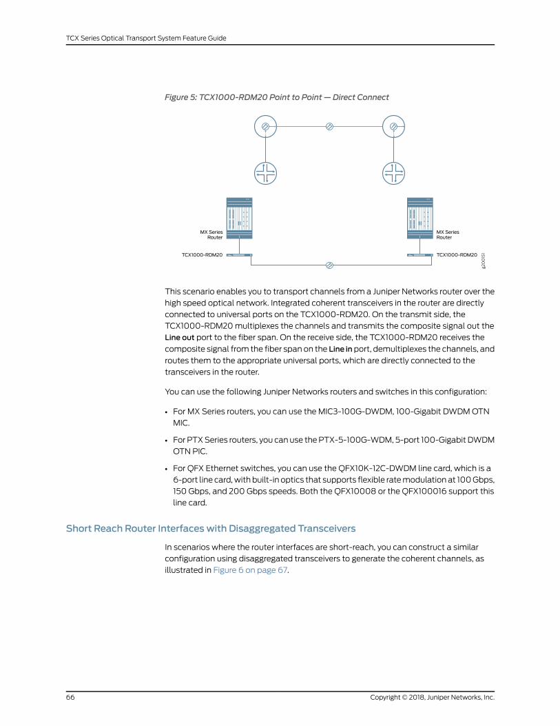
Figure 5: TCX1000-RDM20 Point to Point — Direct Connect
MXSeriesRouter
TCX1000-RDM20
MX SeriesRouter
TCX1000-RDM20
g200151
This scenario enables you to transport channels from a Juniper Networks router over the
high speed optical network. Integrated coherent transceivers in the router are directly
connected to universal ports on the TCX1000-RDM20. On the transmit side, the
TCX1000-RDM20multiplexes the channels and transmits the composite signal out the
Line out port to the fiber span. On the receive side, the TCX1000-RDM20 receives the
composite signal from the fiber span on the Line inport, demultiplexes the channels, and
routes them to the appropriate universal ports, which are directly connected to the
transceivers in the router.
You can use the following Juniper Networks routers and switches in this configuration:
• For MX Series routers, you can use the MIC3-100G-DWDM, 100-Gigabit DWDMOTN
MIC.
• For PTXSeries routers, you canuse thePTX-5-100G-WDM, 5-port 100-Gigabit DWDM
OTN PIC.
• For QFX Ethernet switches, you can use the QFX10K-12C-DWDM line card, which is a
6-port line card,with built-in optics that supports flexible ratemodulationat 100Gbps,
150 Gbps, and 200 Gbps speeds. Both the QFX10008 or the QFX100016 support this
line card.
Short Reach Router Interfaces with Disaggregated Transceivers
In scenarios where the router interfaces are short-reach, you can construct a similar
configuration using disaggregated transceivers to generate the coherent channels, as
illustrated in Figure 6 on page 67.
Copyright © 2018, Juniper Networks, Inc.66
TCX Series Optical Transport System Feature Guide

Figure 6: TCX1000-RDM20 Point to Point — Direct Connect with DisaggregatedTransceivers
MXSeriesRouter
TCX1000-RDM20
MX SeriesRouter
TCX1000-RDM20
g200152
Juniper NetworksCoherent Transponder
Juniper NetworksCoherent Transponder
In this configuration, short reach optical interfaces on the router are connected to the
client ports on a disaggregated transceiver, which connects the channels directly to the
universal ports on the TCX1000-RDM20. On the transmit side, the TCX1000-RDM20
multiplexes the channels present on the universal ports and transmits the composite
signalout the lineport to the fiber span.On the receive side, theTCX1000-RDM20receives
the composite signal on the line port, demultiplexes the channels and routes them to
the appropriate universal ports, which are directly connected to the disaggregated
transceivers.
You can use the following Juniper Networks routers and disaggregated transceivers in
this configuration:
• For routers, you can use either the MX Series or PTX Series routers
• For disaggregated transceivers, you can use Juniper Networks BTI7800with the
Universal Forwarding Modules (UFM): UFM3 with coherent CFP and UFM6.
NOTE: This release of the proNXOptical Director does not support controlandmanagement of UFM3 and UFM6 transponders.
Simple High Capacity Point-to-Point Using TCX1000-RDM20 andMultiplexer/Demultiplexer
To limit the number of universal ports that you use so that you can have room for future
expansion, you can connect an optical multiplexer to a universal port and connect your
transceivers to themultiplexer. For this configuration, you can pair the TCX1000-RDM20
witheither theTCX1000-2D8CMDor the JuniperNetworksBTI7800-FMD96.Theexample
in Figure 7 on page 68 uses the BTI7800-FMD96. This configuration supports up to 96 x
200 Gbps coherent channels with 50 GHz spacing using only a single universal port on
the TCX1000-RDM20. This allows full fill of the spectrum formaximum system capacity
67Copyright © 2018, Juniper Networks, Inc.
Chapter 7: Understanding ROADMNode Configurations

while using the minimum number of universal ports on the TCX1000-RDM20 to allow
for later system expansion.
Figure 7: TCX1000-RDM20 Point-to-Point with FixedMultiplexer/Demultiplexer
BTI7800-FMD96
MX SeriesRouter
Client Ports
TCX1000-RDM20
MX SeriesRouter
TCX1000-RDM20
BTI7800-FMD96
g200153
Line Port
On the transmit side, the coherent channels on the router interfaces connect directly to
theclientportson theBTI7800-FMD96,whichmultiplexes thechannelsandsends them
out the composite line port to the universal port on the TCX1000-RDM20. The
TCX1000-RDM20 further multiplexes the channels and sends the composite signal out
the line port of the TCX1000-RDM20 to the fiber span. At the receive side, the
TCX1000-RDM20 receives the composite signal from the fiber span on the Line In port,
demultiplexes the channels and routes the signal to the Line In port of the
BTI7800-FMD96, which further demultiplexes the channels and routes them to the
clients ports of the BTI7800-FMD96, which are directly connected to the transceivers in
the router.
You can also build this configuration using coherent interfaces in the router (as shown
in Figure 7 on page 68) or with disaggregated coherent transceivers between the router
and themultiplexer/demultiplexer.
To build this configuration using coherent interfaces in the router, you can use:
• For MX Series routers, you can use the MIC3-100G-DWDM, 100-Gigabit DWDMOTN
MIC.
• For PTXSeries routers, you canuse thePTX-5-100G-WDM, 5-port 100-Gigabit DWDM
OTN PIC.
• For QFX switches, you can use theQFX10K-12C-DWDM line card, which is a 6-port line
card, with built-in optics that supports flexible ratemodulation at 100Gbps, 150Gbps,
and 200 Gbps speeds. Both the QFX10008 or the QFX100016 support this line card.
• For the fixedmultiplexer-demultiplexer, you can use the BTI7800-FMD96.
• For a colorless multiplexer-demultiplexer, you can use the TCX1000-2D8CMD.
Copyright © 2018, Juniper Networks, Inc.68
TCX Series Optical Transport System Feature Guide

To build this configuration with disaggregated coherent transceivers between the router
and themultiplexer/demultiplexer, you can use:
• The MX Series or the PTX Series routers or the QFX10008 or the QFX100016 switch
• For the fixed optical multiplexer-demultiplexer you can use the BTI7800-FMD96.
• For the disaggregated transceivers, you can use the BTI7800 Universal Forwarding
Modules (UFM): UFM3 with coherent CFP and the UFM6.
NOTE: This release of the proNXOptical Director does not support controlandmanagement of UFM3 and UFM6 transponders.
• For a colorless multiplexer-demultiplexer, you can use the TCX1000-2D8CMD.
TCX1000-RDM20Direct Connect with FixedMultiplexer/Demultiplexer DeployedSimultaneously
Themultiplexer and direct connect solution can also be deployed simultaneously as
shown in Figure 8 on page 69.
Figure8: DirectConnectwithFixedMultiplexer/DemultiplexerDeployedSimultaneously
Juniper NetworksCoherent Transponder
Juniper NetworksCoherent Transponder
g200154
BTI7800-FMD96
TCX1000-RDM20
BTI7800-FMD96
Juniper NetworksCoherent Transponder
Juniper NetworksCoherent Transponder
TCX1000-RDM20
Client Ports
Line Port
In this topology, five channels from the disaggregated coherent transceivers, connect to
the clients ports of the BTI7800-FMD96 fixedmultiplexer. On the transmit side, the
channels are multiplexed and sent out the composite line side of the BTI7800-FMD96,
which is directly connected to a universal port on the TCX1000-RDM20. The
TCX1000-RDM20 further multiplexes the channels, along with any directly connected
channels, and routes thecomposite signal out the lineport to the fiber span.At the receive
side, the TCX1000-RDM20 receives the composite signal from the fiber span on the Line
In port, demultiplexes the channels and routes them to the receive line side of the
BTI7800-FMD96, which further demultiplexes the channels and routes them to the
directly connected disaggregated transceivers.
This configuration provides a dense, low-loss solution for combining the channels, but
the frequency of each channel is locked to the port of the fixed BTI7800-FMD96. The
additional coherent transceiver directly connected to the TCX1000-RDM20 universal
port is effectively on a colorless port andbecause it is tunable, you canuse it as a standby
channel for all the channels connected on the client ports of the BTI7800-FMD96. This
69Copyright © 2018, Juniper Networks, Inc.
Chapter 7: Understanding ROADMNode Configurations
configuration provides a remotely reconfigurable solution and the direct connect
transceivers can be used to replace any of the channels on the BTI7800-FMD96 in the
event of their failure.
You can use the following Juniper Networks products to build this configuration:
• For the fixed optical multiplexer you can use the BTI7800-FMD96.
• For disaggregated transceivers, you can use Juniper Networks BTI7800with the
Universal Forwarding Modules (UFM): UFM3 with coherent CFP and the UFM6.
NOTE: This release of the proNXOptical Director does not support controlandmanagement of UFM3 and UFM6 transponders.
• For colorless applications, you canuse theTCX1000-2D8CMDmultiplexer to add/drop
channels or you can connect channels directly to the TCX1000-RDM20 (as shown
with the backup channel transponder).
Release History Table DescriptionRelease
The TCX Series Optical Transport System, Release 1.0, supports onlypoint-to-point, single link topologies.
1.0
RelatedDocumentation
TCX1000 Series Product Applications on page 57•
• TCX1000-RDM20 Universal Port Rules on page 61
• TCX Series Optical Transport System Capacities on page 63
• TCX1000 Programmable ROADMOverview on page 27
UnderstandingMulti-Degree ROADMNodes
Pass-through enables you to configure multi-degree ROADM nodes and pass express
traffic between ROADM degrees. This topic provides an overview of the channel
connectivity when using pass-through versus directly connected add/drop channels.
These subjects are included:
• Understanding Pass-Through Connections on page 70
• Understanding Add/Drop Channel Connectivity in Multi-Degree ROADM
Nodes on page 72
Understanding Pass-Through Connections
TheTCX1000-RDM20pass-through featureenables you tocreatemulti-degreeswitching
nodesand ring,mesh,and linearmulti-spannetworkconfigurations.Pass-throughenables
channels to be switched from one degree to another within the same ROADM node.
Channelsconfigured to take thepass-throughpathenterononedegree, aredemultiplexed
Copyright © 2018, Juniper Networks, Inc.70
TCX Series Optical Transport System Feature Guide

and routed to the designated pass-through universal port on the other ROADM degree,
which multiplexes the channels and sends them out the line port of ROADM degree to
the next node in the path.
Figure 9 on page 71 highlights the allowable channel connectivity for this pass-through
configuration.
Figure 9: Allowable Channel Connectivity Using Pass-Through
In this configuration, channels can be add/dropped to any of the three directions served
by the node based on which ROADM degree they are connected to or channels can be
passed from one degree to another over the pass-through path between each degree in
the node.
Themulti-degree ROADM node in Figure 9 on page 71 consists of the following ROADM
elements and degrees:
• 3 ROADM degrees:
• Degree 1 is specific to the direction 1: RDM20-A
• Degree 2 is specific to the direction 2: RDM20-B
• Degree 3 is specific to the direction 3: RDM20-C
• 3 ROADM elements:
• ROADM element: RDM20-A serves ROADM degree 1
• ROADM element: RDM20-B serves ROADM degree 2
• ROADM element: RDM20-C serves ROADM degree 3
Using pass-through connections, you can create a flexible connectivity map for the
ROADMnode. By interconnecting all ROADMdegrees to all other ROADMdegreeswithin
the same node using pass-through, you can establish a fully non-blocking switching
matrix.
71Copyright © 2018, Juniper Networks, Inc.
Chapter 7: Understanding ROADMNode Configurations

In Figure9onpage 71, a pass-through connection is configuredbetweenall threeROADM
degrees in the node, enabling full intra-ROADMmesh any-to-any connectivity between
the ROADM degrees:
• Channels to/from direction 1 can connect to/from direction 2
• Channels to/from direction 1 can connect to/from direction 3
• Channels to/from direction 2 can connect to/from direction 3
NOTE: It is important tounderstandthat theTCX1000-RDM20onlyswitcheschannels between its universal ports and its line port. It does not switchchannels from one universal port to another universal on the same ROADMelement. Channels connected to theuniversal ports of theTCX1000-RDM20are alwaysmultiplexed by the ROADM and sent out the ROADM line port.
Connecting and Configuring Pass-Through
To pass-through channels from one ROADM degree to another in a multi-degree node,
you connect twouniversal ports ondifferent ROADMdegreeswithin amulti-degree node
with a fiber cable and you create a logical link between the two universal ports. When
you create a service, you simply select the two service endpoints and the proNX Optical
Director automatically provisions the best path for the service.
You can configure multiple channels to run over a single pass-through connection and
you can create multiple pass-through connections between ROADM degrees in a
multi-degree node.
Understanding Add/Drop Channel Connectivity in Multi-Degree ROADMNodes
Figure 10onpage72 shows the sameconfigurationbut highlights theallowableadd/drop
channel connectivity of the ROADM node.
Figure 10: Allowable Channel Connectivity for Add/Drop Connections
Copyright © 2018, Juniper Networks, Inc.72
TCX Series Optical Transport System Feature Guide
In this configuration, channels can be add/dropped to any of the three directions served
by the node based on which ROADM degree they are connected to.
The allowable add/drop capabilities in this configuration are:
• Channel A can be switched only to/from RDM20-A degree 1
• Channel B can be switched only to/from RDM20-B degree 2
• Channel C can be switched only to/from RDM20-C degree 3
The following channel connectivity is not allowed on the ROADM node in
Figure 10 on page 72:
• Channel A cannot be switched to/from degree 2
• Channel A cannot be switched to/from degree 3
• Channel B cannot be switched to/from degree 1
• Channel B cannot be switched to/from degree 3
• Channel C cannot be switched to/from degree 1
• Channel C cannot be switched to/from degree 2
Themost important thing to understand about directly connecting channels to the
universal (add/drop) ports in multi-degree ROADM nodes is that channels connected
to the universal ports on the TCX1000-RDM20 are considered to be part of that ROADM
degree that they are connected to and are sent or received to/from that ROADM degree.
This capability is referred to as single direction colorless multiplexing. You can configure
any wavelength you want on any universal port, that is the colorless operation and it is
single direction because directly connected channels are always associated with the
ROADM degree to which the channel transceiver is physically connected.
The ROADM node in Figure 10 on page 72 is capable of routing any directly connected
channels to any degree the node serves as long as you connect your transceiver to the
correct ROADM degree. In addition, it is important to take note of which ROADM degree
you attach your transceivers to in multi-degree nodes (sites), to ensure the channel
traverses the shortest path between source and destination.
RelatedDocumentation
Creating Multi-Degree ROADMNodes on page 73•
CreatingMulti-Degree ROADMNodes
This topic describes how you can interconnect the TCX1000-RDM20 to deploy
multi-degree ROADM nodes by using pass-through fiber connections on the universal
ports of the TCX1000-RDM20 to interconnect ROADM degrees in multi-degree nodes.
It includes the following subjects:
• Refresher: Pass-Through Versus Directly Add/Drop Channels on page 74
• Creating 2-Degree ROADMNode Configurations on page 74
73Copyright © 2018, Juniper Networks, Inc.
Chapter 7: Understanding ROADMNode Configurations
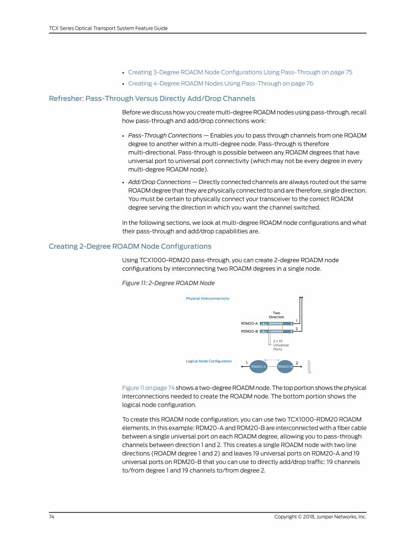
• Creating 3-Degree ROADMNode Configurations Using Pass-Through on page 75
• Creating 4-Degree ROADMNodes Using Pass-Through on page 76
Refresher: Pass-Through Versus Directly Add/Drop Channels
Beforewediscusshowyoucreatemulti-degreeROADMnodesusingpass-through, recall
how pass-through and add/drop connections work:
• Pass-Through Connections—Enables you to pass through channels from one ROADM
degree to another within a multi-degree node. Pass-through is therefore
multi-directional. Pass-through is possible between any ROADM degrees that have
universal port to universal port connectivity (which may not be every degree in every
multi-degree ROADM node).
• Add/Drop Connections—Directly connected channels are always routed out the same
ROADMdegree that theyarephysically connected toandare therefore, singledirection.
Youmust be certain to physically connect your transceiver to the correct ROADM
degree serving the direction in which you want the channel switched.
In the following sections, we look atmulti-degree ROADMnode configurations andwhat
their pass-through and add/drop capabilities are.
Creating 2-Degree ROADMNode Configurations
Using TCX1000-RDM20 pass-through, you can create 2-degree ROADM node
configurations by interconnecting two ROADM degrees in a single node.
Figure 11: 2-Degree ROADMNode
g200307
Physical Interconnections
Logical Node Configuration
2 x 19UniversalPorts
TwoDirection
RDM20-A
RDM20-B
1
2
RDM20-A RDM20-B1 2
Figure 11onpage74showsa two-degreeROADMnode.The topportionshows thephysical
interconnections needed to create the ROADM node. The bottom portion shows the
logical node configuration.
To create this ROADM node configuration, you can use two TCX1000-RDM20 ROADM
elements. In this example: RDM20-AandRDM20-Bare interconnectedwith a fiber cable
between a single universal port on each ROADM degree, allowing you to pass-through
channels between direction 1 and 2. This creates a single ROADM node with two line
directions (ROADM degree 1 and 2) and leaves 19 universal ports on RDM20-A and 19
universal ports on RDM20-B that you can use to directly add/drop traffic: 19 channels
to/from degree 1 and 19 channels to/from degree 2.
Copyright © 2018, Juniper Networks, Inc.74
TCX Series Optical Transport System Feature Guide

Understanding the Pass-Through Capabilities in This Configuration
In Figure 11 on page 74, a single pass-through fiber connection exists between ROADM
degrees: RDM20-A and RDM20-B. The proNXOptical Director automatically selects the
pass-through path for services running between direction 1 and 2.
Understanding the Add/Drop Capabilities in This Configuration
The ROADM node configuration in Figure 11 on page 74 enables single direction colorless
multiplexing:
• Channels connected to RDM20-A are always routed out degree 1.
• Channels connected to RDM20-B are always routed out degree 2.
Youcanadd/dropchannels in either direction 1 or 2.However, youmustphysically connect
the channel to the appropriate ROADM degree. Make sure to connect the channel to a
universal port on the ROADM degree that is responsible for the direction in which you
want the channel to be switched.
For example, to add/dropachannel to/fromdirection 1, youmust connect the transceiver
to a universal port on RDM20-A. Conversely, to add/drop a channel to/from direction 2,
youmust connect the transceiver to a universal port on RDM20-B.
Creating 3-Degree ROADMNode Configurations Using Pass-Through
Using the TCX1000-RDM20, you can create 3-degree nodes like the one shown in
Figure 12 on page 75.
Figure 12: 3-Degree ROADMNode Using Pass-Through
g200308
ThreeDirection
3 x 18UniversalPorts
RDM20-A
2
1
3
RDM20-B
RDM20-C
RDM20-A RDM20-B
RDM20-C
1 2
3
Physical Interconnections
Logical Node Configuration
In Figure 12 on page 75, shows a 3-degree ROADM node configuration. The top portion
of this figure shows the physical interconnections needed to create the ROADM node
and the bottom portion shows the logical node configuration.
To create this 3-degree ROADM node, you can use three TCX1000-RDM20s that are
each interconnected with fiber cables between two universal ports on each ROADM
degree, allowing you to pass-through channels between all three directions in the node.
75Copyright © 2018, Juniper Networks, Inc.
Chapter 7: Understanding ROADMNode Configurations

This leaves 18 universal ports on each ROADM element that you can use for add/drop
traffic.
Understanding the Pass-Through Capabilities in This Configuration
Figure 12 on page 75 has three pass-through paths:
• Path between RDM20-A and RDM20-B
• Path between RDM20-A and RDM20-C
• Path between RDM20-B and RDM20-C
These pass-through paths enable any-to-any directional switching:
• Channels to/from direction 1 can be switched to/from direction 2
• Channels to/from direction 1 can be switched to/from direction 3
• Channels to/from direction 2 can be switched to/from direction 3
Understanding the Add/Drop Capabilities in This Configuration
In Figure 12 on page 75 you can add/drop channels in three possible directions: 1, 2, and
3.However, inorder todoso, youmust connect thechannel transceiver to theappropriate
ROADM degree within the node. Make sure to connect the channel transceiver to a
universal port on the ROADM degree that is responsible for the direction in which you
want the channel to be switched.
• To add/drop a channel to/from direction 1, connect the channel transceiver to a
universal port on RDM20-A.
• To add/drop a channel to/from direction 2, connect the channel transceiver to a
universal port on RDM20-B.
• To add/drop a channel to/from direction 3, connect the channel transceiver to a
universal port on RDM20-C.
Creating 4-Degree ROADMNodes Using Pass-Through
Using the TCX1000-RDM20, you can create 4-degree ROADM node configurations like
the one in Figure 13 on page 77. The top portion of the figure shows the physical
interconnections needed to create the ROADM node. The bottom portion shows the
logical node configuration.
To create this node, you can use four TCX1000-RDM20s that are each interconnected
with fiber cables between three universal ports on each ROADM degree, allowing you to
pass-through channels between all four directions in the node. This leaves 17 universal
ports on each ROADM degree that you can use to add/drop traffic.
Copyright © 2018, Juniper Networks, Inc.76
TCX Series Optical Transport System Feature Guide

Figure 13: 4-Degree ROADMNode Using Pass-Through
g200311
FourDirection
4 x 17UniversalPorts
3
2
1
4
RDM20-B
RDM20-A
RDM20-C
RDM20-D
RDM20-BRDM20-A
RDM20-C RDM20-D
1 2
3 4
Physical Interconnections
Logical Node Configuration
Understanding the Pass-Through Capabilities in This Configuration
The ROADM node in Figure 13 on page 77 has the following pass-through paths:
• Path between RDM20-A and RDM20-B
• Path between RDM20-A and RDM20-C
• Path between RDM20-A and RDM20-D
• Path between RDM20-B and RDM20-D
• Path between RDM20-B and RDM20-C
• Path between RDM20-C and RDM20-D
The ROADM node in Figure 13 on page 77 enables any-to-any directional switching
including:
• Channels to/from direction 1 can connect to/from direction 2
• Channels to/from direction 1 can connect to/from direction 3
• Channels to/from direction 1 can connect to/from direction 4
• Channels to/from direction 2 can connect to/from direction 3
• Channels to/from direction 2 can connect to/from direction 4
• Channels to/from direction 3 can connect to/from direction 4
Understanding the Add/Drop Capabilities in This Configuration
In Figure 13 on page 77, you can add/drop channels in all four directions: 1, 2, 3 and 4.
However, in order to do so, youmust connect the channel transceiver to the appropriate
ROADM degree within the node. Make sure to connect the channel transceiver to a
universal port on the ROADM degree that is responsible for the direction you want the
channel switched.
77Copyright © 2018, Juniper Networks, Inc.
Chapter 7: Understanding ROADMNode Configurations

• To add/drop a channel to/from direction 1, connect the channel transceiver to a
universal port on RDM20-A.
• To add/drop a channel to/from direction 2, connect the channel transceiver to a
universal port on RDM20-B.
• To add/drop a channel to/from direction 3, connect the channel transceiver to a
universal port on RDM20-C.
• To add/drop a channel to/from direction 4, connect the channel transceiver to a
universal port on RDM20-D.
RelatedDocumentation
Understanding Multi-Degree ROADMNodes on page 70•
• TCX1000-RDM20 Universal Port Rules on page 61
• Supported Network Configurations on page 78
Supported Network Configurations
This topic describes and illustrates the various network configurations you can buildwith
the TCX Series Optical Transport System. The following network configurations are
described:
• Linear Multi-Span Multi-Access Network on page 78
• Linear Multi-Span with Spurs on page 79
• Horseshoe with Spur on page 80
• Ring on page 81
• Ring Interconnect on page 81
• Mesh on page 82
Linear Multi-SpanMulti-Access Network
Figure 14 on page 79 shows a five node linear multi-span, multi-access network
configuration. In addition, a seven node configuration is shown that has two endpoints,
which form a dual-homed configuration that is sometimes known as a horseshoe
configuration.
Copyright © 2018, Juniper Networks, Inc.78
TCX Series Optical Transport System Feature Guide

Figure 14:LinearMulti-SpanMulti-AccessNetworkandHorseshoeNetworkConfiguration
g200345
A B C D E
5 Node Example
7 Node Example
Nodes A, E
Nodes B, C, D RDM20
RDM20
UxLine LineUx
RDM20
Line
This network configuration uses the following:
• Each end node (A & E) is a single TCX1000-RDM20, 1-degree ROADM node.
• Middle nodes (B, C, D) consist of two TCX1000-RDM20s, which form a 2-degree
ROADM node interconnected by fiber cables for passing channels to/from degrees.
• Line ports (duplex) connect to system fiber pairs.
• Pass-through fiber connections at 2-degree (middle) sites (B, C, D) uses universal
ports.
• Transceivers can be directly connected the Ux ports on the TCX1000-RDM20 or can
be connected to an optical multiplexer, which in-turn connects to a universal port on
the TCX1000-RDM20.
Linear Multi-Spanwith Spurs
In Figure 15 on page 80 is a linear multi-span network with spurs.
79Copyright © 2018, Juniper Networks, Inc.
Chapter 7: Understanding ROADMNode Configurations

Figure 15: Linear Multi-Span with Spurs
g200346
A B C D E
F G H
Nodes A, E, F, H
Nodes D, G
Nodes B, C
RDM20
RDM20
UxLine LineUx
RDM20
RDM20
RDM20
Line Line
Line
Ux
RDM20
Line
This network configuration uses the following:
• 1-degree sites (A,E,F,H) are formed with a single TCX1000-RDM20 at each end node.
• 2-degree sites (D,G) are formedwith 2 xTCX1000-RDM20at eachpass-throughnode.
• 3-degree sites (B,C) are formed with 3 x TCX1000-RDM20 at each spur node.
• Line ports (duplex) are connected to system fiber pairs.
• Transceivers can be directly connected the Ux ports on the TCX1000-RDM20 or can
be connected to an optical multiplexer, which in-turn connects to a universal port on
the TCX1000-RDM20.
Horseshoewith Spur
In Figure 16 on page 80 is a linear horseshoe network configurationwith dual homed hub
sites (A and E).
Figure 16: Horseshoe with Spur
g200347
Logical Connectivity to Node A
Logical Connectivity to Node E
A E
B D
C
F
Copyright © 2018, Juniper Networks, Inc.80
TCX Series Optical Transport System Feature Guide

This network configuration uses the following:
• Sites B, C, D have redundant paths (and equipment) for connectivity to ROADMnodes
A and E.
• Site F has a shared risk path between ROADM nodes F and D. Connection can then be
optically switched by the ROADM node at D to either direction from nodes D to A and
E.
• Protectedsites (B,C,D)arepreferredbecause theyprovide themost resilient connection.
• Sites with shared risk paths (F) are supported, but provide a less capable solution.
However theymay be used to collect additional traffic on to the networkwhere limited
fiber routesareavailable. If path fromF toE is available it is thepreferredpath toextend
horseshoe path.
Ring
In Figure 17 on page 81 is a ring network configuration.
Figure 17: Ring Network
g200348
A E
B D
C
Nodes A, B, C, D, E RDM20
RDM20
UxLine LineUx
A ring network is composed ofmany 2-degree ROADMnodes. This example ring network
configuration uses the following:
• All 2-degree sites (A,B,C,D,E) are formed with 2 x TCX1000-RDM20 at each
pass-through node.
• Line ports (duplex) connected to system fiber pairs.
• Path forms closed optical ring.
• Transceivers can be directly connected the Ux ports on the TCX1000-RDM20 or can
be connected to an optical multiplexer, which in-turn connects to a universal port on
the TCX1000-RDM20.
Ring Interconnect
In Figure 18 on page 82 is a ring interconnect network configuration.
81Copyright © 2018, Juniper Networks, Inc.
Chapter 7: Understanding ROADMNode Configurations

Figure 18: Ring Interconnect Network
g200349
A E
B D
F
GC
Nodes D
RDM20
RDM20
RDM20
RDM20
Line Line
Line
Line
Nodes A, B, C, D, E RDM20
RDM20
Line LineUx
Ux
5 Node Ring Example
3 Node Ring Example
This network configuration uses the following:
• 2-degreesites (A,B,C,E,F,G)are formedwith2xTCX1000-RDM20ateachpass-through
node.
• 4-degree site (D) at ring interconnect is formed with 4 x TCX1000-RDM20.
• Line ports (duplex) connect to system fiber pairs.
• The 4-degree site (D) allows traffic to be switched from one ring to another.
• Transceivers can be directly connected the Ux ports on the TCX1000-RDM20 or can
be connected to an optical multiplexer, which in-turn connects to a universal port on
the TCX1000-RDM20.
Mesh
Themeshnetwork inFigure 19onpage82combinescharacteristicsofall previousnetwork
configurations.
Figure 19: Mesh Example 1
g200350
A E
B D
C
H
F
G
This network configuration uses the following:
Copyright © 2018, Juniper Networks, Inc.82
TCX Series Optical Transport System Feature Guide

• 1-degree site (H) is formed with a single TCX1000-RDM20
• 2-degree site (G) is formed with 2 x TCX1000-RDM20
• 3-degree sites (B,C) are formed with 3 x TCX1000-RDM20
• 4-degree sites (A,D, E) are formed with 4 x TCX1000-RDM20
• 5-degree site (F) is formed with 5 x TCX1000-RDM20
• Sites up to 20-degrees are supported by the TCX1000-RDM20
• Line ports (duplex) connect to system fiber pairs
• Transceivers can be directly connected the Ux ports on the TCX1000-RDM20 or can
be connected to an optical multiplexer, which in-turn connects to a universal port on
the TCX1000-RDM20.
Figure 20 on page 83 shows a high resilience mesh network configuration.
Figure 20: Mesh Example 2
g200351
A
B F
C
D
J
H
G
E
This network configuration is highly resilient to multiple failures—each site has three
independent paths to any other site:
• 3-degree sites (A,B,C,D,E,F,G,H) are formed with 3 x TCX1000-RDM20
• 8-degree site (J) is formed with 8 x TCX1000-RDM20
• Sites up to 20-degrees are supported by the TCX1000-RDM20
• Line ports (duplex) connect to system fiber pairs
• Transceivers can be directly connected the Ux ports on the TCX1000-RDM20 or can
be connected to an optical multiplexer, which in-turn connects to a universal port on
the TCX1000-RDM20.
RelatedDocumentation
• Creating Multi-Degree ROADMNodes on page 73
• Understanding Multi-Degree ROADMNodes on page 70
• TCX1000-RDM20 Universal Port Rules on page 61
83Copyright © 2018, Juniper Networks, Inc.
Chapter 7: Understanding ROADMNode Configurations

Copyright © 2018, Juniper Networks, Inc.84
TCX Series Optical Transport System Feature Guide

CHAPTER 8
UnderstandingROADMNodeMultiplexingStrategies
• Understanding Direct Multiplexing on the TCX1000-RDM20 ROADM on page 85
• Understanding TCX1000-RDM20 and TCX1000-2D8CMDMultiplexing
Capabilities on page 88
• Understanding Single Direction Channelized Multiplexing with TCX1000-RDM20 and
BTI7800-FMD96 Fixed Multiplexer on page 94
Understanding Direct Multiplexing on the TCX1000-RDM20 ROADM
Figure 21 on page 85 shows a 2-degree linear multi-span ROADM node. The top portion
shows the physical interconnections needed to create the ROADM node. The bottom
portion shows the logical node configuration.
Figure21:SingleDirectionAdd/DropColorlessDirectMultiplexingwithTCX1000-RDM20ROADMg200312
SingleDirectionAdd/Drop
DirectMultiplexing
Colorless
RDM20-A
RDM20-B
1
2
RDM20-A RDM20-B1 2
Physical Interconnections
Logical Node Configuration
The 2-degree ROADM node in Figure 21 on page 85 provides single direction add/drop
colorlessmultiplexinganddemultiplexing.AsingleuniversalportoneachROADMelement
is used for a pass-through connection, leaving 38 ports for add/drop traffic: 19 universal
ports on RDM20-A and 19 universal ports on RDM20-B for directly connected add/drop
traffic.
85Copyright © 2018, Juniper Networks, Inc.

The following sections describe howmultiplexing and demultiplexing works for directly
connected add/drop channels and for pass-through connections in this configuration.
Multiplexing
Add/Drop Channels
Directly connected channels aremultiplexed and sent out the line port of their respective
ROADM degree:
• Channels directly connected to ROADM degree: RDM20-A are multiplexed and sent
out direction 1.
• Channels directly connected to ROADM degree: RDM20-B are multiplexed and sent
out direction 2.
The thing to keep in mind with this configuration is that the direction the channel is
added/dropped depends on the physical ROADM degree the channel is connected to.
Pass-Through Channels
Channels that you configure to take a pass-through connections are multiplexed as:
• Pass-through channels coming in from direction 1 are demultiplexed by RDM20-A and
passed to the RDM20-B pass-through port. The pass-through channels are then
multiplexed by RDM20-B and sent out direction 2.
• Pass-through channels coming in fromdirection 2 are demultiplexed by RDM20-B and
passed to the RDM20-A pass-through port. The pass-through channels are then
multiplexed by RDM20-A and sent out direction 1.
Demultiplexing
Add/Drop Channels
• Channels arriving from direction 1, arrive on the line port of RDM20-A and are
demultiplexed by RDM20-A and dropped to their appropriate universal ports.
• Channels arriving from direction 2, arrive on the line port of RDM20-B and are
demultiplexed by RDM20-B and dropped to their appropriate universal ports.
Pass-Through Channels
Channels that you configure to take the pass-through connection are demultiplexed as:
• Pass-throughchannels fromdirection 1arriveon the lineportofRDM20-A.Thechannels
are demultiplexed and sent to the RDM20-A pass-through port and passed to the
RDM20-B pass-through port. The pass-through channel is thenmultiplexed by
RDM20-B and sent out direction 2.
• Pass-throughchannels fromdirection2arriveon the lineportofRDM20-B.Thechannels
are demultiplexed and sent to the RDM20-B pass-through port and passed to the
RDM20-A pass-through port. The pass-through channel is thenmultiplexed by
RDM20-A and sent out direction 1.
Copyright © 2018, Juniper Networks, Inc.86
TCX Series Optical Transport System Feature Guide

Summary of Direct ROADMMultiplexing
Figure 22: Summary of Direct ROADMMultiplexing
g200352
RDM20Line
Transceivers Ux
Referring to Figure 22 on page 87, coherent transceiver interfaces connect directly to the
universal (Ux) ports on the TCX1000-RDM20. This provides channel ports which are:
• Colorless
• Single direction (defined by TCX1000-RDM20 direction)
• Supports non-coherent channels
ThenumberofUxportsavailableatanodedependsonwhat isused forother connections.
For examplearepass-throughconnections configuredon theuniversal ports. Tocalculate
the available universal ports on each ROADM degree, use the following:
Thereare20-(N-1) universal portsavailableon theROADMdegree,whereN is thenumber
of directions at a ROADM node.
For example:
• In a 1-degree site (terminal) there are 20 available universal ports on the ROADM
• In 2-degree site (terminal) thereare 19availableuniversal portsoneachROADMdegree
for a total of 2x19=38 universal ports for the ROADM node
• In 3-degree site (terminal) thereare 18availableuniversal portsoneachROADMdegree
for a total of 3x18=54 universal ports for the ROADM node
RelatedDocumentation
Understanding TCX1000-RDM20 and TCX1000-2D8CMDMultiplexing Capabilities
on page 88
•
• Supported Network Configurations on page 78
• TCX1000-RDM20 Universal Port Rules on page 61
87Copyright © 2018, Juniper Networks, Inc.
Chapter 8: Understanding ROADMNode Multiplexing Strategies

Understanding TCX1000-RDM20 and TCX1000-2D8CMDMultiplexing Capabilities
The TCX1000-RDM20 has twenty universal ports that you can use for directly
adding/dropping channels onto a ROADM degree, passing channels through from one
ROADM degree to another, or for connecting an optical multiplexer-demutiplexer to
add/dropmore channels to the TCX1000-RDM20.
This section describes how you can use the TCX1000-2D8CMDmultiplexer with the
TCX1000-RDM20 for both single andmulti-direction colorless add/dropmultiplexing.
This sectionalsodescribeshowmultiplexinganddemultiplexingworks in thisconfiguration
for both directly added/dropped channels and pass-through channels.
NOTE: The passive combiner-splitter architecture of the TCX1000-2DCMDrequires you use only coherent transceivers. Channels received from the lineports are broadcast to all eight client ports. The connected coherenttransceiver is responsible for selecting its corresponding wavelength andfiltering out the impact of the unwanted broadcast channels. As such, theTCX1000-2D8CMD is suitable for coherent only applications.
The following subjects are included:
• Single Direction Add/Drop Colorless Multiplexing with TCX1000-2D8CMD on page 88
• Multi-Direction Add/Drop Colorless Multiplexing with TCX1000-RDM20 and
TCX1000-2D8CMD on page 91
Single Direction Add/Drop Colorless Multiplexing with TCX1000-2D8CMD
Figure 23 on page 89 shows a 2-degree linear multi-span ROADM node. The top portion
shows the physical interconnections needed to create the ROADM node. The bottom
portion shows the logical node configuration.
Copyright © 2018, Juniper Networks, Inc.88
TCX Series Optical Transport System Feature Guide

Figure 23: Single Direction Add/Drop Colorless Multiplexing with TCX1000-2D8CMD
g200315
TCX1000-2D8CMD TCX1000-2D8CMD
ColorlessMultiplexing
SingleDirectionAdd/Drop
Colorless
1
2
RDM20-A
RDM20-B
RDM20-A RDM20-B
2D8CMD-A 2D8CMD-B
1 2
Physical Interconnections
Logical Node Configuration
In Figure 23 on page 89 is a ROADM node that includes two elements, RDM20-A and
2D8CMD-A form one ROADM element serving degree 1 and RDM20-B and 2D8CMD-B
form another ROADM element serving degree 2. This 2-degree node provides single
direction colorlessmultiplexing for connected channels; connected channels are always
routed out the ROADM degree that they are physically connected to. As such, in this
configuration, you can add/drop channels for direction 1 by connecting your transceivers
to either RDM20-A or 2D8CMD-A and you can add/drop channels for direction 2 by
connecting your transceivers to either RDM20-B or 2D8CMD-B.
Also in this ROADMnode configuration, a single universal port on eachTCX1000-RDM20
is used to pass channels between the two ROADM degrees. Another universal port
connects the line port of the TCX1000-2D8CMDmultiplexer. This configuration leaves
you 18 universal ports on RDM20-A and 18 universal ports on RDM20-B, as well as 8
additional ports on each TCX1000-2D8CMD.
The following sections describe howmultiplexing and demultiplexing works for directly
connected add/drop channels and for pass-through channels in this configuration.
Multiplexing
Add/Drop Channels
• Channels directly connected to the clients ports (Cx) on 2D8CMD-Aare combinedand
broadcast out the Lx Out port(s) to the connected universal port on RDM20-A, which
multiplexes the channels and routes them out degree 1.
• Channels directly connected to the clients ports (Cx In) on 2D8CMD-B are combined
and broadcast out the Lx Out port(s) to the connected universal port on RDM20-B,
multiplexes the channels and routes them out degree 2.
89Copyright © 2018, Juniper Networks, Inc.
Chapter 8: Understanding ROADMNode Multiplexing Strategies

Pass-Through Channels
The configuration in Figure 23onpage89enables you topass through channels between
degree 1 and degree 2:
• Pass-throughchannels fromdirection 1 are receivedon the lineport ofRDM20-A,which
demultiplexes the channels and sends it out the universal port on RDM20-A to the
universalportonRDM20-B.RDM20-Bmultiplexes thepass-throughchannelandsends
it out direction 2.
• Pass-through channels from direction 2 are received on the line port of RDM20-B,
which demultiplexes the channel and sends it out the universal port on RDM20-B to
the universal port on RDM20-A. RDM20-Amultiplexes the pass-through channel and
sends it out direction 1.
Demultiplexing
Add/Drop Channels
• Channels coming in from direction 1 are demultiplexed by RDM20-A and dropped to
the appropriate universal port. Channels destined to 2D8CMD-A, now present at Lx In
port of 2D8CMD-A , are broadcast to the 8 channel output ports (Cx Out ports) on
2D8CMD-A.
• Channels coming in from direction 2 are demultiplexed by RDM20-B and dropped to
the appropriate universal port. Channels destined to 2D8CMD-B, now present at the
Lx In port, are broadcast to the 8 channel output ports (Cx Out ports) on 2D8CMD-B.
NOTE: The connected coherent transceivers are responsible for selectingtheir correspondingwavelength and filtering out the impact of the unwantedbroadcast channels. As such, the TCX1000-2D8CMD is suitable for coherentonly applications.
Pass-Through Channels
• Apass-throughchannel coming in fromdirection 1 is demultiplexedbyROADMelement
RDM20-A and sent out the UxOut pass-through port on RDM20-A to the Ux In
pass-through port on RDM20-B, which multiplexes the pass-through channel and
sends it out direction 2.
• Apass-throughchannel coming in fromdirection2 isdemultiplexedbyROADMelement
RDM20-B and sent out the UxOut pass-through port on RDM20-B to the Ux In
pass-through port on RDM20-A, which multiplexes the pass-through channel and
sends it out direction 1.
Summary of Colorless Single DirectionMultiplexing
Figure 24 on page 91 summarizes colorless single direction multiplexing.
Copyright © 2018, Juniper Networks, Inc.90
TCX Series Optical Transport System Feature Guide

Figure 24: Colorless One-Direction Multiplexing
g200354
2D8CMD RDM20LineTransceivers
Line Port
Client Cx Ports
Client Cx Ports
Ux
Coherent transceiver interfaces connect to the eight client ports on the
TCX1000-2D8CMD. The line port of the TCX1000-2D8CMD connects to a singleUx port
on the TCX1000-RDM20. The TCX1000-2D8CMD can be thought of as an 8:1 port
expander. This configuration provides channel ports that are:
• Colorless
• Single direction (direction is defined by the connected TCX1000-RDM20 degree)
NOTE: There is no spectral policing on the TCX1000-2D8CMD, so that if thesame channel is applied to two or more client ports of a singleTCX1000-2D8CMD, interference can occur between the channels.
NOTE: This configuration does not work with non-coherent channels.
Multi-DirectionAdd/DropColorlessMultiplexingwithTCX1000-RDM20andTCX1000-2D8CMD
Figure 25 on page 92 shows a 2-degree linear multi-span ROADM node that supports
multi-direction add/drop capability. The topportion shows thephysical interconnections
needed to create the ROADM node. The bottom portion shows the logical node
configuration.
91Copyright © 2018, Juniper Networks, Inc.
Chapter 8: Understanding ROADMNode Multiplexing Strategies

Figure 25: Multi-Direction Add/Drop Colorless Multiplexing with TCX1000-RDM20 andTCX1000-2D8CMD
g200314
MultiDirectionAdd/Drop
TCX1000-2D8CMD
1+1 ColorlessMultiplexing
Colorless
1
2
RDM20-A
RDM20-B
RDM20-A RDM20-B1 2
2D8CMD-A
Physical Interconnections
Logical Node Configuration
The 2-degree ROADM node in Figure 25 on page 92 provides multi-direction add/drop
colorless multiplexing by leveraging the TCX1000-2D8CMD dual line ports. In this node
configuration,asingleuniversalportoneachROADMelement (RDM20-AandRDM20-B)
is used for a pass-through connection. Another universal port on each ROADM element
connects to the two line ports (Lx) of the TCX1000-2D8CMD. This configuration leaves
you36universal ports for add/drop traffic: 18universal portsonRDM20-Aand 18universal
ports on RDM20-B, as well as 8 additional ports on the TCX1000-2D8CMD.
The following sections describe howmultiplexing and demultiplexing works for directly
connected add/drop channels and for pass-through channels in this configuration.
Multiplexing
Add/Drop Channels
Channels directly connected to the Cx In ports on ROADM element: 2D8CMD-A are
combined and broadcast out both Lx Out ports to the connected universal ports on
RDM20-A and RDM20-B. Channels configured to take the path to direction 1 are
multiplexed by RDM20-A and sent out direction 1. Channels configured to take the path
to direction 2 are multiplexed by RDM20-B and sent out direction 2.
The TCX1000-2D8CMD broadcasts the same composite signal out both line ports and
the ROADM (TCX1000-RDM20) elements manage the channel selection. This allows a
channel connected to the TCX1000-2D8CMD to be routed out either degree 1 or degree
2 of the ROADM node. This provides flexibility to re-configure the network remotely,
allowing for rapid re-configuration of services, tidal traffic flow or automated optical
restoration applications.
Copyright © 2018, Juniper Networks, Inc.92
TCX Series Optical Transport System Feature Guide
The TCX1000-2D8CMD provides the simplest form of amulti-direction solution where
the output from the 8 to 1 combiner is broadcast in 2 directions. This is primarily intended
for 1 + 1 redundancy applications.
NOTE: The TCX1000-2D8CMD broadcasts channels present on the Cx In
ports out both Lx Out ports. You specify the path for these channels on the
TCX1000-RDM20when you define the channel service.
Pass-Through Channels
The2-degreeROADMnode inFigure 25onpage92enables you topass throughchannels
from degree 1 to degree 2 and from degree 2 to degree 1:
• Pass-throughchannels fromdirection 1 are receivedon the lineport ofROADMelement:
RDM20-A, which demultiplexes the channel and sends it out the universal port on
RDM20-A to the universal port on RDM20-B. RDM20-Bmultiplexes the pass-through
channel and sends it out direction 2.
• Pass-throughchannels fromdirection2are receivedon the lineportofROADMelement:
RDM20-B, which demultiplexes the channel and sends it out the universal port on
RDM20-B to the universal port on RDM20-A. RDM20-Amultiplexes the pass-through
channel and sends it out direction 1.
Demultiplexing
Add/Drop Channels
Channels coming in from direction 1 that are destined for ROADM element: 2D8CMD-A
are demultiplexed by RDM20-A and sent over the universal port to the connected line
port on 2D8CMD-A. 2D8CMD-Ademultiplexes the channels and broadcasts them to the
Cx Out ports.
Channels coming in from direction 2 that are destined for ROADM element: 2D8CMD-A
are demultiplexed by RDM20-B and sent over the universal port to the connected line
port on 2D8CMD-A. 2D8CMD-Ademultiplexes the channels and broadcasts them to the
Cx Out ports.
NOTE: The TCX1000-2D8CMD broadcasts channels present on the Cx In
ports out both Lx Out ports. You specify the path for these channels on the
TCX1000-RDM20when you define the channel service.
Pass-Through Channels
• Apass-throughchannel coming in fromdirection 1 is demultiplexedbyROADMelement
RDM20-A and sent out the UxOut port on RDM20-A to the Ux In port on RDM20-B,
which multiplexes the pass-through channel and sends it out direction 2.
• Apass-throughchannel coming in fromdirection2 isdemultiplexedbyROADMelement
RDM20-B and sent out the UxOut port on RDM20-B to the Ux In port on RDM20-A,
which multiplexes the pass-through channel and sends it out direction 1.
93Copyright © 2018, Juniper Networks, Inc.
Chapter 8: Understanding ROADMNode Multiplexing Strategies

Summary Colorless 1+1 RedundancyMultiplexing
Figure 26: Summary Colorless 1+1 Multiplexing
g200355
LineLine
2D8CMD
RDM20RDM20
Transceivers
Client Cx PortsClient Cx Ports
Line PortLine Port
Ux Ux
Figure 26 on page 94 summarizes colorless 1+1 redundancy multiplexing. Coherent
transceiver interfaces connect to the eight TCX1000-2D8CMD client ports. The two line
ports from the TCX1000-2D8CMD each connect to a single universal port on
TCX1000-RDM20. This configuration provides channel ports that are:
• Colorless
• Multi-direction — channels can be sent/received in two directions, as determined by
the TCX1000-RDM20 configuration
NOTE: The TCX1000-2D8CMD broadcasts channels present on the Cx In
ports out both Lx Out ports. The configuration of the connected
TCX1000-RDM20 is responsible for determining which channels aremultiplexed by the TCX1000-RDM20 and sent out its line port.
RelatedDocumentation
Understanding Multi-Degree ROADMNodes on page 70•
• Supported Network Configurations on page 78
• Creating Multi-Degree ROADMNodes on page 73
Understanding Single Direction ChannelizedMultiplexing with TCX1000-RDM20 andBTI7800-FMD96 FixedMultiplexer
Figure 27 on page 95 shows a 2-degree linear multi-span ROADM node that supports
single direction fixed-grid add/drop capability. The top portion shows the physical
interconnections needed to create the ROADM node. The bottom portion shows the
logical node configuration.
Copyright © 2018, Juniper Networks, Inc.94
TCX Series Optical Transport System Feature Guide

Figure 27: Single Direction ChannelizedMultiplexing with TCX1000-RDM20 andBTI7800-FMD96 FixedMultiplexer
g200313
BTI7800-FMD96
BTI7800-FMD96
SingleDirectionAdd/Drop
ChannelizedMultiplexing
Fixed Grid
1
2
RDM20-A
RDM20-B
RDM20-A RDM20-B
FMD96-A FMD96-B
1 2
Physical Interconnections
Logical Node Configuration
The 2-degree linear multi-span ROADM node in Figure 27 on page 95 provides single
direction fixed-gridadd/dropmultiplexingbyusing the JuniperNetworksBTI7800-FMD96
optical multiplexer-demultiplexer. The BTI7800-FMD96 is a 96 channel fixed
multiplexer-demultiplexer that provides fixed grid access to all 96 wavelengths in the
DWDM 50 GHz channel plan. In this ROADM node configuration, a single universal port
on each ROADM element (RDM20-A and RDM20-B) is used for a pass-through
connection. Another universal port on each ROADM element connects to the line port of
theBTI7800-FMD96: theuniversalportonRDM20-Aconnects to the lineportofFMD96-A
and the universal port on RDM20-B connects to the line of FMD96-B. This configuration
enables 96 channels in direction 1 and 96 channels and direction 2.
The following sections describe howmultiplexing and demultiplexing works for directly
connected add/drop channels and for pass-through channels in this configuration.
Multiplexing
Add/Drop Channels
• Channels directly connected to the clients ports of FMD96-A aremultiplexed and sent
out the line port to the universal port on RDM20-A. RDM20-A further multiplexes the
channels and sends them out the line port of RDM20-A to direction 1.
• Channels directly connected to the clients ports of FMD96-B aremultiplexed and sent
out the line port to the universal port on RDM20-B. RDM20-B further multiplexes the
channels and sends them out the line port of RDM20-B to direction 2.
Pass-Through Channels
The2-degreeROADMnode in Figure 27onpage95enables you topass throughchannels
from direction 1 to direction 2 and from direction 2 to direction 1:
95Copyright © 2018, Juniper Networks, Inc.
Chapter 8: Understanding ROADMNode Multiplexing Strategies

• Pass-throughchannels fromdirection 1 are receivedon the lineport ofROADMelement:
RDM20-A, which demultiplexes the channels and sends them out the universal port
onRDM20-Ato theuniversalportonRDM20-B.RDM20-Bmultiplexes thepass-through
channel and sends them out direction 2.
• Pass-throughchannels fromdirection2are receivedon the lineportofROADMelement:
RDM20-B, which demultiplexes the channels and sends them out the universal port
onRDM20-Bto theuniversalportonRDM20-A.RDM20-Amultiplexes thepass-through
channels and sends them out direction 1.
Demultiplexing
Add/Drop Channels
Channels coming in from direction 1 that are destined for ROADM element: FMD96-A
are demultiplexed by RDM20-A and sent over the universal port to the connected line
port on FMD96-A. FMD96-A demultiplexes the channels and sends them to the Cx Out
ports.
Channels coming in from direction 2 that are destined for ROADM element: FMD96-B
are demultiplexed by RDM20-B and sent over the universal port to the connected line
port on FMD96-B. FMD96-B demultiplexes the channels and sends them to the Cx Out
ports.
Pass-Through Channels
• Apass-throughchannel coming in fromdirection 1 is demultiplexedbyROADMelement
RDM20-A and sent out the UxOut port on RDM20-A to the Ux In port on RDM20-B,
which multiplexes the pass-through channel and sends it out direction 2.
• Apass-throughchannel coming in fromdirection2 isdemultiplexedbyROADMelement
RDM20-B and sent out the UxOut port on RDM20-B to the Ux In port on RDM20-A,
which multiplexes the pass-through channel and sends it out direction 1.
Summary of Single Direction ChannelizedMultiplexing with TCX1000-RDM20 andBTI7800-FMD96 FixedMultiplexer
Figure28:SummaryofSingleDirectionChannelizedMultiplexingwithTCX1000-RDM20and BTI7800-FMD96 FixedMultiplexer
g200353
FMD96 RDM20LineTransceivers
Line Port
Client Cx Ports
Client Cx Ports
Ux
Copyright © 2018, Juniper Networks, Inc.96
TCX Series Optical Transport System Feature Guide

Figure 28 on page 96 summarizes single direction channelizedmultiplexing with the
TCX1000-RDM20andBTI7800-FMD96fixedmultiplexer.Coherent transceiver interfaces
connect to the client ports of the BTI7800-FMD96, which provides 96 ports on a fixed
50 GHz grid. The BTI7800-FMD96 Line port connects to single universal port on the
TCX1000-RDM20.
NOTE: Spectrum is not reserved on the TCX1000-RDM20. Channel slots onthe Line port are only used if you provision them.
This provides a channel ports which are:
• Colored (fixed 50 GHz grid)
• Single direction (defined by the TCX1000-RDM20 direction)
• Supports non-coherent channels
RelatedDocumentation
• Understanding Direct Multiplexing on the TCX1000-RDM20 ROADM on page 85
• Understanding TCX1000-RDM20 and TCX1000-2D8CMDMultiplexing Capabilities
on page 88
97Copyright © 2018, Juniper Networks, Inc.
Chapter 8: Understanding ROADMNode Multiplexing Strategies

Copyright © 2018, Juniper Networks, Inc.98
TCX Series Optical Transport System Feature Guide

CHAPTER 9
TCX1000-RDM20ConfigurationOverviewand Software Upgrades
• TCX1000-RDM20 Port Administrative States on page 99
• TCX1000-RDM20 Links and Services Overview on page 100
• Third-PartyWavelength Support on page 104
• TCX1000 Series Software Upgrades on page 106
TCX1000-RDM20 Port Administrative States
Port Administrative State and Operational State
The ports on the TCX1000-RDM20 have two possible states:
• Operational — The operational state is read-only and can be either Up, to indicate the
port is operational, or Down, to indicate the port is not operational.
• Administrative — The administrative state is configurable and can be set to In-service
orOut-of-service.
NOTE: To enable a link, set the administrative state of the port to In-service.
Placing a portOut-of-service automatically blocks all associated spectrum. It does not
change any of the provisioned configuration parameters so that the connection
automatically returns to the samestate itwas inwhenplacedback to In-service, providing
external conditions remain the same as well. AnOut-of-service port continues to accept
provisioning changes but will not optically apply any of them until it is placed back into
service.
Input and output ports are initially specified during connection creation but can be also
be changed at any time. This can be done without restriction, whether the connection is
in or out-of-service and whether it is blocked or unblocked.
Auto Provisioning of Ports
By default, the following ports are set toOut-of-service on a new device:
99Copyright © 2018, Juniper Networks, Inc.
• Line ports—When you define an external link for the line port, the administrative state
on both the line port and the OSC 0 port are auto-provisioned to In-service.
• Universal ports —When you create a physical-link to amultiplexer-demultiplexer or
to a Junos port, the universal port is auto-provisioned to In-service.
• OSC ports — Auto-provisioning of these ports works in the following manner:
• TheOSC port is the pluggable port and after the supplied optical SFP transceiver is
plugged in, the administrative state is automatically changed to In-service.
RelatedDocumentation
TCX1000 Programmable ROADMOverview on page 27•
• TCX1000-RDM20 Optical Monitoring Points on page 36
TCX1000-RDM20 Links and Services Overview
All TCX1000 Series devices are configured andmanaged by proNXOptical Director. This
topicdescribes thebasic conceptof linksandservices for theTCXSeriesOpticalTransport
System. It includes the following subjects:
• Links on page 100
• Services on page 102
Links
The various ports on the TCX1000-RDM20 can be connected to different devices
dependingon theport. The line port connects to a fiber systemandultimately, to another
TCX1000-RDM20 lineport. Youcanconnect theuniversal portson theTCX1000-RDM20
to:
• Juniper Networks integrated and disaggregated transceivers
• Third-party transceivers
• Fixed grid and colorless optical multiplexer-demultiplexer
• Another TCX1000-RDM20 universal port (pass-through connection)
These devicesmust be connected to the TCX1000-RDM20both physically and logically.
To logically connect these devices to the TCX1000-RDM20, you create links. Links are
bidirectional and point-to-point. The possible links you can create are described in
Table 16 on page 101.
NOTE: The source and destination designations are used only to distinguishbetween the two link endpoints. They are assigned arbitrarily and areinterchangeable.
Copyright © 2018, Juniper Networks, Inc.100
TCX Series Optical Transport System Feature Guide

Table 16: Supported Optical Links
NotesDestination Link EndpointsSource Link Endpoint
Line port on TCX1000-RDM20LineportonTCX1000-RDM20
Creates a pass-through connection betweenROADMdegreeswithin a single ROADMnodeto enable ROADM degree switching for ring,mesh, and linear multi-span topologies.
Another TCX1000-RDM20 universal portUniversal port onTCX1000-RDM20
Enables 8 channels from theTCX1000-2D8CMD to bemultiplexed over asingleuniversalporton theTCX1000-RDM20.
The TCX1000-2D8CMD is a colorlessmultiplexer-demultiplexer that enables bothsingle andmulti-direction add/dropcapabilities.
A line port on a TCX1000-2D8CMD opticalmultiplexer-demultiplexer
Universal port onTCX1000-RDM20
Enables 96 x 200 Gbps coherent channelsfrom the BTI7800-FMD96 to bemultiplexedover a single universal port.
The BTI7800-FMD96 is a fixedmultiplexer-demultiplexer that supports singledirection add/drop capability.
A lineport onaBTI7800-FMD96 fixedopticalmultiplexer-demultiplexer
Universal port onTCX1000-RDM20
An integrated optical interface in a JuniperNetworks router or QFX10K switch.
Universal port onTCX1000-RDM20
A BTI7800 Universal Forwarding Module(UFM) UFM3 and UFM6 transponders
NOTE: This release of the proNX OpticalDirector does not support control andmanagement of UFM3 and UFM6transponders.
Universal port onTCX1000-RDM20
An integrated optical interface in a JuniperNetworks router or QFX10K switch.
A client port on aTCX1000-2D8CMD opticalmultiplexer-demultiplexer
A BTI7800 Universal Forwarding Module(UFM) UFM3 and UFM6 transponders
NOTE: This release of the proNX OpticalDirector does not support control andmanagement of UFM3 and UFM6transponders.
A client port on aTCX1000-2D8CMD opticalmultiplexer-demultiplexer
101Copyright © 2018, Juniper Networks, Inc.
Chapter 9: TCX1000-RDM20 Configuration Overview and Software Upgrades

Table 16: Supported Optical Links (continued)
NotesDestination Link EndpointsSource Link Endpoint
NOTE: The BTI7800-FMD96 is a fixedchannel multiplexer/demultiplexer, whichmeans that eachclient port is associatedwitha hardcoded fixed wavelength. When youcreate a link between an BTI7800-FMD96client port and a compatible optical interfaceon a Juniper Networks router or switch, youmustensure that the routeror switchendpointis configuredwith awavelength thatmatchesthe wavelength of the client port on theBTI7800-FMD96.
An optical interface in a Juniper Networksrouter or QFX10K switch.
A client port on aBTI7800-FMD96 fixed opticalmultiplexer-demultiplexer.
A BTI7800 Universal Forwarding Module(UFM) UFM3 and UFM6 transponders
NOTE: This release of the proNX OpticalDirector does not support control andmanagement of UFM3 and UFM6transponders.
A client port on aBTI7800-FMD96 fixed opticalmultiplexer-demultiplexer.
Services
Services run over the links defined on the TCX1000-RDM20 ports. First youmust create
a link and after that is complete, you can provision a service to run over the link. Services
typically traverse multiple links.
An optical service provides wavelength connectivity between service endpoints. It is
defined by its wavelength and the endpoints that it interconnects. A service exists as a
series of cross-connects that route the service wavelength through the
multiplexers-demultiplexers, ROADM elements, and line amplifiers that make up the
optical network.
When you create a service, you specify the wavelength and the two endpoints that the
wavelength interconnects.
The thing to keep in mind when provisioning services is that they are provisioned
endpoint-to-endpoint. The proNX Optical Director supports A-to-Z provisioning and
activation of optical services on Juniper Networks compatible routers and switches and
BTISeriesdevices.Youselect thesourceanddestinationendpointsand theproNXOptical
Director automatically configures the service between the two service endpoints.
Creating the service:
• Includes control and configuration of endpoint transceiver(s)
• Sets up of the service, such a 100 Gbps Ethernet transport including wavelength
• Opens the optical path through network to allow transport of channel
• Opens the optical path and brings it under control for performance optimization
• Creates the service, for example from router port to router port
Copyright © 2018, Juniper Networks, Inc.102
TCX Series Optical Transport System Feature Guide

See Figure 29 on page 103 and Table 17 on page 103 for the allowed endpoints when you
create a service. You can create a service from A, B, C, or D to E, F, G, or H.
Figure 29: Optical Service Endpoints
g200194
ROADMNode
TCX1000-RDM20
ROADMNode
TCX1000-RDM20
SupportedStandaloneor IntegratedTransponder
SupportedStandaloneor IntegratedTransponder
SupportedStandaloneor IntegratedTransponder
SupportedStandaloneor IntegratedTransponder
Multiplexer/Demultiplexer
Tail Facility Unconfigured
Multiplexer/Demultiplexer
D
C
BA
G
HFE
Alien Device Alien Device
Alien Device Alien Device
Tail Facility Configured
Table 17: Allowed Optical Service Endpoints
UsageLabelEndpoint
You typically use this endpointwhenyousetupaserviceto an alien device that is attacheddirectly to a universalport on the TCX1000-RDM20.
A or E inFigure 29 on page 103
A topologically-unconnected universalport on a TCX1000-RDM20. This is auniversal port that does not have a linkassociated with it.
You typically use this endpointwhenyousetupaserviceto analien device that is attached to a client port on themultiplexer/demultiplexer.
B or F inFigure 29 on page 103
A universal port on a TCX1000-RDM20that is topologically connected to amultiplexer/demultiplexer. This is auniversal port that has a link to amultiplexer/demultiplexer.
You typically use this endpointwhenyousetupaserviceto a supported tail facility endpoint that is attacheddirectly to a universal port on the TCX1000-RDM20.
C or G inFigure 29 on page 103
A supported tail facility endpoint wherethe endpoint is topologically connectedto a universal port on aTCX1000-RDM20. This is a transceiverport at the supported tail facilityendpoint.
You typically use this endpointwhenyousetupaserviceto a supported tail facility endpoint that is attached toa client port on the multiplexer/demultiplexer.
D or H inFigure 29 on page 103
A supported tail facility endpoint wherethe endpoint is topologically connectedto a client port on amultiplexer/demultiplexer. This is atransceiver port at the supported tailfacility endpoint.
For lower wavelength fan-out, you can deploy the TCX1000-RDM20without a
multiplexer-demultiplexer and use the universal ports to connect directly to client
transponders (labels A, C, E, G in Figure 29 on page 103). For larger wavelength fan-out,
you can deploy BTI7800-FMD96 fixedmultiplexer-demultiplexer to give access to all
96wavelengthsconcurrently (labelsB,D, F,H inFigure29onpage 103).Or, for acolorless,
103Copyright © 2018, Juniper Networks, Inc.
Chapter 9: TCX1000-RDM20 Configuration Overview and Software Upgrades
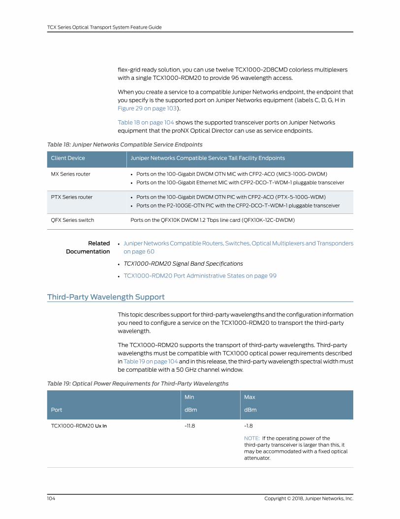
flex-grid ready solution, you can use twelve TCX1000-2D8CMD colorless multiplexers
with a single TCX1000-RDM20 to provide 96 wavelength access.
When you create a service to a compatible Juniper Networks endpoint, the endpoint that
you specify is the supported port on Juniper Networks equipment (labels C, D, G, H in
Figure 29 on page 103).
Table 18 on page 104 shows the supported transceiver ports on Juniper Networks
equipment that the proNX Optical Director can use as service endpoints.
Table 18: Juniper Networks Compatible Service Endpoints
Juniper Networks Compatible Service Tail Facility EndpointsClient Device
• Ports on the 100-Gigabit DWDMOTNMIC with CFP2-ACO (MIC3-100G-DWDM)
• Ports on the 100-Gigabit Ethernet MIC with CFP2-DCO-T-WDM-1 pluggable transceiver
MX Series router
• Ports on the 100-Gigabit DWDMOTN PIC with CFP2-ACO (PTX-5-100G-WDM)
• Ports on the P2-100GE-OTN PIC with the CFP2-DCO-T-WDM-1 pluggable transceiver
PTX Series router
Ports on the QFX10K DWDM 1.2 Tbps line card (QFX10K-12C-DWDM)QFX Series switch
RelatedDocumentation
JuniperNetworksCompatibleRouters,Switches,OpticalMultiplexersandTransponders
on page 60
•
• TCX1000-RDM20 Signal Band Specifications
• TCX1000-RDM20 Port Administrative States on page 99
Third-PartyWavelength Support
This topicdescribessupport for third-partywavelengthsand theconfiguration information
you need to configure a service on the TCX1000-RDM20 to transport the third-party
wavelength.
The TCX1000-RDM20 supports the transport of third-party wavelengths. Third-party
wavelengths must be compatible with TCX1000 optical power requirements described
inTable 19onpage 104and in this release, the third-partywavelength spectralwidthmust
be compatible with a 50 GHz channel window.
Table 19: Optical Power Requirements for Third-PartyWavelengths
Max
dBm
Min
dBmPort
-1.8
NOTE: If the operating power of thethird-party transceiver is larger than this, itmay be accommodated with a fixed opticalattenuator.
-11.8TCX1000-RDM20 Ux In
Copyright © 2018, Juniper Networks, Inc.104
TCX Series Optical Transport System Feature Guide

Table 19: Optical Power Requirements for Third-PartyWavelengths (continued)
Max
dBm
Min
dBmPort
2.0-6.6TCX1000-RDM20 UxOut
2.1-5.1BTI7800-FMD96_ In (Channel_In)
-1.7-13.4BTI7800-FMD96_ Out (Channel_Out)
The proNX Optical Director does not control or manage third-party optical interfaces
supplying the third-party wavelengths to the TCX1000-RDM20. As a result, the
configuration of links and services for third-party wavelengths differs from the
configuration of Juniper Networks compatible devices. For Juniper Networks compatible
devices, you can simply select the service endpoints and proNX Optical Director
automatically configures the entire service across the across the optical network.
The configuration of links and services for third-party optical interfaces supplying
third-party wavelengths to the TCX1000-RDM20 is slightly different. Links are not
applicable to third-party optical interfaces, because the proNX Optical Director cannot
control or manage these optical interfaces and is completely unaware of them, you
cannot select them as link source and destination endpoints.
Services are applicable to third-partywavelengths, but the configuration still differs from
configuring services on Juniper Networks compatible optical interfaces. Because the
proNX Optical Director is unaware of the third-party optical interface, you cannot select
it asa service endpoint. Insteadyoumust select theuniversal port towhich the third-party
optical interface is connected as the service endpoint and the proNX Optical Director
creates the optical path for the third-party wavelength by:
• Opening the optical path through the network to allow transport of the third-party
channel. The third-party channel is treated as any other channel on the
TCX1000-RDM20. It is multiplexed and demultiplexed by the TCX1000-RDM20s and
channel performancemanagement is automatically applied to it.
• Creating the service from TCX1000-RDM20 universal port to universal port
NOTE: You are responsible for setting up the third-party transceiver opticalservices that run over the optical path.
RelatedDocumentation
TCX1000-RDM20 Links and Services Overview on page 100•
• TCX1000 Series Product Applications on page 57
• TCX1000-RDM20 Universal Port Rules on page 61
105Copyright © 2018, Juniper Networks, Inc.
Chapter 9: TCX1000-RDM20 Configuration Overview and Software Upgrades

TCX1000 Series Software Upgrades
This topic provides an overview of how software upgrades work on the TCX1000 Series
of devices and it includes the following subjects:
• Software Upgrade Overview on page 106
• Overview of Performing Software Upgrades on the TCX1000-RDM20 on page 106
Software Upgrade Overview
TCX1000 Series devices support nondisruptive software upgrades where the device
retains the last known configuration and passes traffic uninterrupted. You can perform
software upgrades on a single device or onmultiple devices simultaneously. All software
upgrades are initiated from the proNX Optical Director.
Software upgrades are delivered as a single file, which contains all the software for the
various components of thedevice. TheTCX1000-RDM20usesa twobankboot structure
which allows for the running load to remain in place while the new load is installed to,
and run from, the other bank. This enables reversion to the original running load should
an upgrade fail or you choose to revert before the process completes. Banks are referred
to as A and B and either can function as the currently active bank.
There are two phases in the software upgrade process: Stage and Activate. After you
select the proNXOptical Director SFTP server and filename in themanagement system,
you can chose to either Stage or Activate the upgrade.
• Staging copies the software upgrade file to the TCX1000 Series device.
• Activate performs the upgrade on the device
After you initiate the software upgrade, the management system notifies you when the
upgrade is complete.
Overview of Performing Software Upgrades on the TCX1000-RDM20
To upgrade the software on a TCX1000 device:
1. Download the TCX1000 software from the Juniper Networks website.
2. Save the TCX1000 software upgrade file to one of the proNX Optical Director SFTP
servers.
NOTE: The path of the software upgrade file must be relative to thedirectory you providedwhen theSFTP serverwas configured, or if no pathwas selected, then it must be relative to your SFTP home directory. Youcan also browse the SFTP server for the software upgrade file.
3. In proNX Optical Director:
Copyright © 2018, Juniper Networks, Inc.106
TCX Series Optical Transport System Feature Guide

a. Select the SFTP server on which the software upgrade file resides.
b. Select the name of the TCX1000 software upgrade file.
c. Select the Stage operation to copy the software upgrade file to the TCX1000
device. Ensure this tasks completes successfully before proceeding.
d. Select the Activate operation to upgrade the device software. Ensure this tasks
completes successfully before proceeding.
RelatedDocumentation
• proNX Optical Director Device Backup and Restore Support
• proNX Optical Director System and Optical Control Levels on page 37
• proNX Optical Director Control and Management Software Components on page 40
107Copyright © 2018, Juniper Networks, Inc.
Chapter 9: TCX1000-RDM20 Configuration Overview and Software Upgrades

Copyright © 2018, Juniper Networks, Inc.108
TCX Series Optical Transport System Feature Guide

CHAPTER 10
TCX1000-RDM20 Optical SupervisoryChannel
• TCX1000-RDM20 OSCManagement Overview on page 109
• TCX1000-RDM20 OSC Connection Overview on page 110
TCX1000-RDM20OSCManagement Overview
This topic describes the operation of the optical supervisory channel for this release of
the TCX1000-RDM20.
In this release of the TCX1000-RDM20 the OSC is used for two purposes:
• Enables zero-channel turn-up by providing an optical link between the twomanaged
devices allowing proNX Optical Director to measure span loss between the two
managed devices without having any channels turned up.
• Assists with the optical safety for the system. If both the OSC Ethernet link state is
down and the preamplifier is in active loss of signal (LOS) alarm, the booster is
automatically disabled. Recovery is automatic when the fault is repaired.
NOTE: In this release, no data communications are sent over the OSC.
In this release, an OSC kit is provided with each TCX1000-RDM20 that includes a 1511
nm SFP transceiver to provide the OSC channel. The 1511 nmOSC is multiplexed, along
with the C-band DWDM channels present on the universal ports, and the composite
signal is sent out the LineOutport to the fiber system. At the receiving TCX1000-RDM20,
the composite line signal is received on the Line In port. The C-band channels are routed
to the appropriate universal ports and the OSC is routed to theOSC0 port. TheOSC0
port is connected to the OSC SFP transceiver which is connected to the internal CPU via
an internal Ethernet switch.
109Copyright © 2018, Juniper Networks, Inc.

NOTE: Although the TCX1000-RDM20 can support either a 1511 nmOSC ontheOSC0 port or a 1611 nmOSConOSC 1 port we support only the use of the
provided 1511 nmOSC. As a result, theOSC 1 port is not used in this release
and you can use this port, to connect an instrumentation grade opticaltime-domain reflectometer (OTDR) at 1611 nm for optical fibercharacterization.
RelatedDocumentation
TCX1000-RDM20 OSC Connection Overview on page 110•
• proNX Optical Director System and Optical Control Levels on page 37
• TCX1000-RDM20 Automatic Laser Shutdown on page 24
• proNX Optical Director Control and Management Software Components on page 40
TCX1000-RDM20OSC Connection Overview
This topic provides an overview of how you connect the OSC. It includes the following
subjects:
There are three ports associated with the OSC on the front panel of TCX1000-RDM20:
• OSC—Accepts an SFP optical transceiver that provides the transmit and receive
functions of the OSCwavelength
• OSC0—Optical port that multiplexes and demultiplexes the 1511 nmOSC signal on
the Line port
• OSC 1—Optical port that multiplexes and demultiplexes the 1611 nmOSC signal on
the Line port
In this release, these ports are used in the following manner:
• TheOSC 1 port is not used in this release. As a result, you can use theOSC 1 port, to
connect an instrumentation grade optical time-domain reflectometer (OTDR) at 1611
nm for optical fiber characterization.
• TheOSC0 port is used for OSC communications. In this release, you connectOSC0
port to the SFP in theOSC port with a patch cord provided in the OSC kit. It transmits
and receives the 1511 nm channel from the SFP optical transceiver supplied in the OSC
kit.
• TheOSC port is an SFP cage that accepts an SFP optical transceiver for the OSC
function. In this release,weprovideanOSCkitwitheachTCX1000-RDM20that includes
a 1511 nm, 100Mbps SFP optical transceiver that provides the OSC signal. You insert
the transceiver into theOSC port and then use the provided patch cord to connect the
1511 nm channel to theOSC0 port.
These connections are illustrated in Figure 30 on page 111.
Copyright © 2018, Juniper Networks, Inc.110
TCX Series Optical Transport System Feature Guide

Figure 30: TCX1000-RDM20OSC Connections
TCX1000-RDM20
Fiber SystemConnection
ROADMOptics
DCN 0 DCN 1 Line
OSCSFP
OSC OSC 0 OSC 1
CPU
1511EthernetSwitch
g200198
Because the OSC signal is coupled to theWDM signal after the integrated VOA, it does
not receive any additional attenuation over the loss of the system fiber. As a result, when
operating the TCX1000-RDM20 on short spans, additional external lossmust be added.
If the OSC power at the receive side of the SFP port is measured to be above -7 dBm,
then you should install the fixed loss attenuators supplied in the OSC kit.
RelatedDocumentation
• TCX1000-RDM20 OSCManagement Overview on page 109
• proNX Optical Director Control and Management Software Components on page 40
111Copyright © 2018, Juniper Networks, Inc.
Chapter 10: TCX1000-RDM20 Optical Supervisory Channel

Copyright © 2018, Juniper Networks, Inc.112
TCX Series Optical Transport System Feature Guide

CHAPTER 11
Alarms
• TCX1000-RDM20 Alarm Overview on page 113
• proNX Optical Director Alarms on page 114
• TCX1000-RDM20 Hardware Alarm Types and Behavior on page 115
• TCX1000-RDM20 Hardware Alarms and Probable Cause on page 116
• TCX1000-RDM20 Port Alarms and Probable Causes on page 119
• TCX1000-RDM20 Port Alarm Thresholds on page 121
• TCX1000-RDM20 Amplifier Alarms and Probable Causes on page 122
• TCX1000-RDM20 Amplifier Alarm Thresholds on page 124
• TCX1000-RDM20 Connection Alarms and Probable Causes on page 125
• TCX1000-RDM20 Connection Alarm Thresholds on page 127
TCX1000-RDM20 AlarmOverview
In the TCX Series Optical Transport System, there are two different sources of optical
alarms:
• TCX1000-RDM20managed device alarms — The TCX1000-RDM20 is responsible for
all conditions that are validated on the device itself. Examples include any alarms
associated with the port, connection, or amplifier.
• proNXOpticalDirector generatedalarms—Theoptical control layer (OCL)application
withinproNXOpticalDirector generatesalarms for conditions that cannotbe validated
by the managed device. Examples include span or nodal loss out-of-range (OOR)
alarms.
An alarm is a persistent indication of a fault that clears onlywhen the triggering condition
has been resolved. A current list of problemsoccurring on the network component is kept
in the form of an active alarm list.
A list of cleared faults is also maintained.
In general alarms are:
• Persistent indication
• Clear only when the triggering condition resolved
113Copyright © 2018, Juniper Networks, Inc.

• Active alarm list
• Cleared faults list is maintained
• Filtering of alarms to severity levels
• Alarm severity: critical, major, minor warning
Current alarms are maintained along with historical alarms for a configurable period of
time. This allows debugging of network issues after a fault has occurred.
By default, alarm event notification is turned off. Each user can choose to enable alarm
event notification. If enabled, event notifications are sent for all alarms raised. There is
alsoa throttlingmechanismso that youarenot inundatedwithnotificationsduringalarm
storms.
RelatedDocumentation
TCX1000-RDM20 Port Alarms and Probable Causes on page 119•
• TCX1000-RDM20 Hardware Alarms and Probable Cause on page 116
• TCX1000 Optical Transport System Performance Monitoring on page 45
proNXOptical Director Alarms
The proNX Optical Director control andmanagement software generates the alarms
described in Table 20 on page 114.
Table 20: proNXOptical Director Generated Alarms
Condition causeproNXOptical Director Alarm
This alarm is raised when proNX Optical Director losescommunicationwithadevice.This is typicallybecauseadiscoveryhas failed due to network communication issues with the proNXOpticalDirector. If thedevicebecomes reachable again thealarmclears.
Device Unreachable
Port on the TCX1000-RDM20 is pointing to a device that is notdiscoverable.This canbea lineport, universalport, or aconnectionon the TCX1000-RDM20.
Network link with farend undiscovered
The nodal loss OOR alarm is raised against both ends of auniversal port pass-through to indicate the issuemay bewith theupstream TCX1000-RDM20 UxOut port or the downstreamTCX1000-RDM20 Ux In port, or the cross-connect fiber itself.
Nodal loss is the loss in the fiber between two pass-throughuniversal ports. The range is 0 dB to 5.2 dB.
This alarm is raised when the nodal loss is out of operationalrange of the equipment between the two pass-through universalports.
Nodal loss out of range (OOR)
Copyright © 2018, Juniper Networks, Inc.114
TCX Series Optical Transport System Feature Guide

Table 20: proNXOptical Director Generated Alarms (continued)
Condition causeproNXOptical Director Alarm
Indicates an incomplete link configuration on the line portsbetween the two TCX1000-RDM20s. For example, if youconfigured the lineport ononeendof the linkbutdidnot configurethe line port on the other end.
Incomplete network link
Indicatesan incompatiblewavelengthata topology level. Appliesonly to universal ports connected to a Junos router transceiverand the frequencies do not match.
Farend
Themeasured span loss on a network link is outside the rangethat the TCX1000-RDM20 can compensate for.
Tx-span-loss-out-of-range
Rx-span-loss out-of-range
Indicates the TCX1000-RDM20 is under management by theproNX Optical Director but there has not been any telemetryinformation received for 5 minutes.
OTI Communication Failure
TheproNXOpticalDirector generatesa topologymismatchalarmif you select a multi-span channel path that runs overTCX1000-RDM20 hardware from TCX Series Optical TransportSystem, Release 1.0. The TCX1000-RDM20 hardware in TCXSeries Optical Transport System, Release 1.0 requires a firmwareupgrade to support multi-span capabilities. You can downloadthe new TCX1000-RDM20 firmware here: TCX1000-RDM20software download.
Topology mismatch
RelatedDocumentation
proNX Optical Director Span Loss Management, Alarms and Metrics on page 49•
• proNX Optical Director Performance Monitors and Metrics on page 47
• proNX Optical Director System and Optical Control Levels on page 37
• proNX Optical Director Control and Management Software Components on page 40
TCX1000-RDM20Hardware Alarm Types and Behavior
This topic describes the various types of TCX1000-RDM20 alarms and their behavior. It
includes the following subjects:
• Optical Power Alarms on page 115
• Temperature Alarm Behavior on page 116
Optical Power Alarms
The TCX1000-RDM20 supports the following optical power alarms.
Input/Output LowDegrade Alarms
These alarms indicate that the optical power measured on the port or interface has
dropped below the Input/output Low Degrade Threshold value. To clear this fault, an
115Copyright © 2018, Juniper Networks, Inc.
Chapter 11: Alarms

optical input power equal to the Input/output Low Degrade Threshold plus the
Input/Output Low Degrade Hysteresis must be restored at the port or interface.
Input/Output Overload Alarms
These alarms indicate that the optical power measured on the port or interface has
exceeded the Input/output Overload Threshold value. To clear this fault, an optical input
power equal to the Input/outputOverloadThresholdminus the InputOverloadHysteresis
must be restored at the port or interface.
Loss of Output (LOO) Alarms
LOOalarms indicate that theoptical powermeasuredon theport or interfacehasdropped
below the Loss of Output threshold value. To clear this fault, an optical power equal to
the loss of output threshold plus the loss of output hysteresis must be restored at the
port or interface.
Loss of Signal (LOS)
LOSalarms indicate that theopticalpowermeasuredon theportor interfacehasdropped
below the Loss of Signal Threshold value. To clear this fault, an optical input power equal
to the Loss of Signal Threshold plus the Loss of Signal Hysteresis must be restored at
the port or interface.
Temperature Alarm Behavior
When the card temperature Out-Of-Range alarm is asserted, it indicates that the
TCX1000-RDM20ambient temperature sensor has gone significantly outside the design
operating range. The TCX1000-RDM20will continue to remain fully operational on a
best effort basis under these conditions, however performancemay fall outside of
specifications.NoTCX1000-RDM20systemwill beautomatically shutdownunder these
circumstances, however if ambient temperature climbs high enough the powermodules
will eventually shutoff. This canbeexpected tohappen in the rangeof65-70°Cambient.
The TCX1000-RDM20 contains a number of internal heating elements for stabilizing
various optical components. These have over-temperature protection on an individual
basis that is not tied directly to the card temperature alarm. Overheating of any of these
elements can lead to the affected heater being shut down. This will be alarmed as a
service or non-service affecting hardware failure as appropriate.
RelatedDocumentation
TCX1000-RDM20 Alarm Overview on page 113•
• proNX Optical Director Alarms on page 114
TCX1000-RDM20Hardware Alarms and Probable Cause
Table 21 onpage 117 describes theTCX1000-RDM20hardware alarmsand their probable
causes and location.
Copyright © 2018, Juniper Networks, Inc.116
TCX Series Optical Transport System Feature Guide

Table 21: TCX1000-RDM20 Hardware Alarms and Probable Causes and Location
Severity
Description
Probable Cause/
Probable LocationAlarmEntity
MajorFanmodule not present
Probable-cause-direction= Not Applicable
Probable-cause-location=Not Applicable
fru-missingfan 0
MajorFanmodule has failed
Probable-cause-direction= Not Applicable
Probable-cause-location=Not Applicable
fru-failfan 0
MajorFanmodule not present
Probable-cause-direction= Not Applicable
Probable-cause-location=Not Applicable
fru-missingfan 1
MajorFanmodule has failed
Probable-cause-direction= Not Applicable
Probable-cause-location=Not Applicable
fru-failfan 1
MajorPower module not present
Probable-cause-direction= Not Applicable
Probable-cause-location=Not Applicable
fru-missingpower module 0
MajorPower module has failed
Probable-cause-direction= Not Applicable
Probable-cause-location=Not Applicable
fru-failpower module 0
MinorNo input power to power module
Probable-cause-direction= Not Applicable
Probable-cause-location=Not Applicable
input-power-failpower module 0
MinorCommunications failure to FRU
Probable-cause-direction= Not Applicable
Probable-cause-location=Not Applicable
fru-comms-failurepower module 0
117Copyright © 2018, Juniper Networks, Inc.
Chapter 11: Alarms

Table 21: TCX1000-RDM20 Hardware Alarms and Probable Causes and Location (continued)
Severity
Description
Probable Cause/
Probable LocationAlarmEntity
MajorPower module not present
Probable-cause-direction= Not Applicable
Probable-cause-location=Not Applicable
fru-missingpower module 1
MajorPower module has failed
Probable-cause-direction= Not Applicable
Probable-cause-location=Not Applicable
fru-failpower module 1
MinorNo input power to power module
Probable-cause-direction= Not Applicable
Probable-cause-location=Not Applicable
input-power-failpower module 1
MinorCommunications failure to FRU
Probable-cause-direction= Not Applicable
Probable-cause-location=Not Applicable
fru-comms-failurepower module 1
CriticalPotentially serviceaffectinghardware failure
Probable-cause-direction= Not Applicable
Probable-cause-location=Not Applicable
hardware-fail-SAcard
MinorNon service affecting hardware failure
Probable-cause-direction= Not Applicable
Probable-cause-location=Not Applicable
hardware-fail-NSAcard
MinorTemperature outside operating limits
Probable-cause-direction= Not Applicable
Probable-cause-location=Not Applicable
temperature-oorcard
RelatedDocumentation
TCX1000-RDM20 Alarm Overview on page 113•
• TCX1000-RDM20 Hardware Alarm Types and Behavior on page 115
Copyright © 2018, Juniper Networks, Inc.118
TCX Series Optical Transport System Feature Guide

TCX1000-RDM20 Port Alarms and Probable Causes
Table 22 on page 119 describes details the various port alarms the TCX1000-RDM20 can
raise and their probable cause and location.
Table 22: TCX1000-RDM20 Port Alarms and Probable Causes and Locations
Severity
Description
Probable Cause/
Probable LocationAlarmPort
MinorPort Ethernet link status is down
Probable-cause-direction=bidirectional
Probable-cause-location=FAREND
ethernet-link-downETH CRAFT
MinorPort Ethernet link status is down
Probable-cause-direction=bidirectional
Probable-cause-location=FAREND
ethernet-link-downEthernet DCN 0
MinorPort Ethernet link status is down
Probable-cause-direction=bidirectional
Probable-cause-location=FAREND
ethernet-link-downEthernet DCN 1
MajorLoss of input
Probable-cause-direction=rx
Probable-cause-location=FAREND
optical-losLine Port
MinorInput power degraded
Probable-cause-direction=rx
Probable-cause-location=FAREND
input-low-degradeLine Port
MajorLoss of Output
Probable-cause-direction=tx
Probable-cause-location=NEAREND
optical-looLine Port
MajorOutput VOA cannot achieve targetattenuation
Probable-cause-direction=rx
Probable-cause-location=FAREND
attenuation-unattainableLine Port
119Copyright © 2018, Juniper Networks, Inc.
Chapter 11: Alarms

Table 22: TCX1000-RDM20 Port Alarms and Probable Causes and Locations (continued)
MinorLow Optical Return Loss on Output
Probable-cause-direction=bidirectional
Probable-cause-location=FAREND
optical-return-losLine Port
MinorLoss of input at OSC In
Probable-cause-direction=rx
Probable-cause-location=FAREND
optical-losOSC 0
MinorLoss of OSC at Line In
Probable-cause-direction=tx
Probable-cause-location=NEAREND
optical-looOSC 0
MinorLoss of input at OSC In
Probable-cause-direction=rx
Probable-cause-location=FAREND
optical-losOSC 1
MinorLoss of OSC at Line In
Probable-cause-direction=tx
Probable-cause-location=NEAREND
optical-looOSC 1
MajorNo SFP installed
Probable-cause-direction=bidirectional
Probable-cause-location=NEAREND
pluggable-missingOSC SFP
MajorSFP receiver overload
Probable-cause-direction=rx
Probable-cause-location=FAREND
receiver-overloadOSC SFP
MajorSFP internal fault
Probable-cause-direction=bidirectional
Probable-cause-location=NEAREND
pluggable-failOSC SFP
MajorI2C link to SFP failed
Probable-cause-direction=bidirectional
Probable-cause-location=NEAREND
pluggable-comms-failureOSC SFP
Copyright © 2018, Juniper Networks, Inc.120
TCX Series Optical Transport System Feature Guide

Table 22: TCX1000-RDM20 Port Alarms and Probable Causes and Locations (continued)
MajorEthernet link status is down
Probable-cause-direction=bidirectional
Probable-cause-location=FAREND
ethernet-link-downOSC SFP
MinorLoss of input, Rx LOS
Probable-cause-direction=rx
Probable-cause-location=FAREND
optical-losOSC SFP
RelatedDocumentation
TCX1000-RDM20 Alarm Overview on page 113•
• TCX1000-RDM20 Hardware Alarm Types and Behavior on page 115
• TCX1000-RDM20 Port Alarm Thresholds on page 121
TCX1000-RDM20 Port Alarm Thresholds
Table 23 on page 121 describes the external port alarm threshold values that are
programmable through the proNX Optical Director for the TCX1000-RDM20.
NOTE: Hysteresis value is +/-1.0 dB for all ports and interfaces described inTable 23 on page 121. Hysteresis values are not user configurable.
Table 23: TCX1000-RDM20 External Port Thresholds
Threshold
Starting with TCX SeriesOptical Transport System,Release 1.1
(dBm)
Threshold
Starting with TCX SeriesOptical Transport System,Release 1.0
(dBm)DescriptionHardwareAlarmPort
Range 1: -25.0Range 1: -22.5Loss of signalOptical-losLine In
Range 2: -36.0Range 2: -32.5
Range 1: -22.0Range 1: -19.5InputPowerDegradedInput-low-degrade
Range 2: -33.0Range 2: -29.5
-18.2-17.2Loss of outputOptical-looLine Out
-11-8Loss of signalOptical-losOSC 0/1 In
-41.60-40.20Loss of outputOptical-looOSC 0/1 Out
121Copyright © 2018, Juniper Networks, Inc.
Chapter 11: Alarms

Table 23: TCX1000-RDM20 External Port Thresholds (continued)
Threshold
Starting with TCX SeriesOptical Transport System,Release 1.1
(dBm)
Threshold
Starting with TCX SeriesOptical Transport System,Release 1.0
(dBm)DescriptionHardwareAlarmPort
-15.65-13.75Loss of signalOptical-losUx In
12.65-10.75InputPowerDegradedInput-low-degrade
Release History Table DescriptionRelease
Starting with TCX Series Optical Transport System, Release 1.11.1
Starting with TCX Series Optical Transport System, Release 1.01.0
RelatedDocumentation
TCX1000-RDM20 Alarm Overview on page 113•
• TCX1000-RDM20 Hardware Alarm Types and Behavior on page 115
• TCX1000-RDM20 Port Alarms and Probable Causes on page 119
TCX1000-RDM20 Amplifier Alarms and Probable Causes
Table24onpage 122describes theTCX1000-RDM20amplifier (boosterandpreamplifier)
alarms and their probable causes and location.
Table 24: TCX1000-RDM20 Amplifier Alarms and Probable Causes and Locations
Severity
Description
Probable Cause/
Probable LocationAlarmEntity
MajorAmplifier cannot achieve gain target
Probable-cause-direction="tx"
Probable-cause-location="NEAREND"
amp-gain-not-achievedbooster
MinorAmplifier operating outside the mask
Probable-cause-direction="tx"
Probable-cause-location="NEAREND"
amp-operating-outside-maskbooster
Copyright © 2018, Juniper Networks, Inc.122
TCX Series Optical Transport System Feature Guide

Table 24: TCX1000-RDM20 Amplifier Alarms and Probable Causes and Locations (continued)
Severity
Description
Probable Cause/
Probable LocationAlarmEntity
CriticalLoss of output
Probable-cause-direction="tx"
Probable-cause-location="NEAREND"
optical-loobooster
MinorInput power overload
Probable-cause-direction="rx"
Probable-cause-location="FAREND"
input-overloadbooster
MinorInput power degraded
Probable-cause-direction="rx"
Probable-cause-location="FAREND"
input-low-degradebooster
MajorLoss of input
Probable-cause-direction="rx"
Probable-cause-location="FAREND"
optical-losbooster
MajorAutomatic output power reduction activedue to high return loss or forced APR
Probable-cause-direction="rx"
Probable-cause-location="NEAREND"
auto-power-reductionbooster
MajorAutomatic shutdown due to detected linebreak
Probable-cause-direction="tx"
Probable-cause-location="NEAREND"
automatic-shutdownbooster
MinorAutomatic Line Shutdown system disabled
Probable-cause-direction="tx"
Probable-cause-location="NEAREND"
laser-safety-disabledbooster
MajorAmplifier cannot achieve gain target
Probable-cause-direction="tx"
Probable-cause-location="NEAREND"
amp-gain-not-achievedPreamp
123Copyright © 2018, Juniper Networks, Inc.
Chapter 11: Alarms

Table 24: TCX1000-RDM20 Amplifier Alarms and Probable Causes and Locations (continued)
Severity
Description
Probable Cause/
Probable LocationAlarmEntity
MinorAmplifier being operated outside the gainmask
Probable-cause-direction="tx"
Probable-cause-location="NEAREND"
amp-operating-outside-maskPreamp
CriticalLoss of output
Probable-cause-direction="tx"
Probable-cause-location="NEAREND"
optical-looPreamp
MinorInput power overload
Probable-cause-direction="rx"
Probable-cause-location="FAREND"
input-overloadPreamp
MajorLine failure detected, possible fiber break
Probable-cause-direction="rx"
Probable-cause-location="FAREND"
optical-line-failurePreamp
RelatedDocumentation
TCX1000-RDM20 Alarm Overview on page 113•
• TCX1000-RDM20 Hardware Alarm Types and Behavior on page 115
• TCX1000-RDM20 Amplifier Alarm Thresholds on page 124
TCX1000-RDM20 Amplifier Alarm Thresholds
Table25onpage125describes theamplifieralarmthresholdvalues thatareprogrammable
through the proNX Optical Director for the TCX1000-RDM20.
NOTE: Hysteresis values for all amplifier thresholds is +/-1.0 dB. Hysteresisvalues are not user configurable.
Copyright © 2018, Juniper Networks, Inc.124
TCX Series Optical Transport System Feature Guide
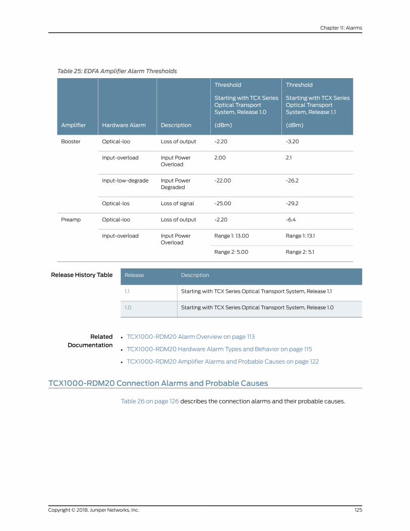
Table 25: EDFA Amplifier Alarm Thresholds
Threshold
Startingwith TCXSeriesOptical TransportSystem, Release 1.1
(dBm)
Threshold
Startingwith TCXSeriesOptical TransportSystem, Release 1.0
(dBm)DescriptionHardware AlarmAmplifier
-3.20-2.20Loss of outputOptical-looBooster
2.12.00Input PowerOverload
Input-overload
-26.2-22.00Input PowerDegraded
Input-low-degrade
-29.2-25.00Loss of signalOptical-los
-6.4-2.20Loss of outputOptical-looPreamp
Range 1: 13.1Range 1: 13.00Input PowerOverload
Input-overload
Range 2: 5.1Range 2: 5.00
Release History Table DescriptionRelease
Starting with TCX Series Optical Transport System, Release 1.11.1
Starting with TCX Series Optical Transport System, Release 1.01.0
RelatedDocumentation
TCX1000-RDM20 Alarm Overview on page 113•
• TCX1000-RDM20 Hardware Alarm Types and Behavior on page 115
• TCX1000-RDM20 Amplifier Alarms and Probable Causes on page 122
TCX1000-RDM20 Connection Alarms and Probable Causes
Table 26 on page 126 describes the connection alarms and their probable causes.
125Copyright © 2018, Juniper Networks, Inc.
Chapter 11: Alarms
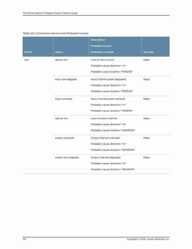
Table 26: Connection Alarms and Probable Causes
Severity
Description
Probable Cause/
Probable LocationAlarmEntity
MajorLoss of input on port
Probable-cause-direction="rx"
Probable-cause-location="FAREND"
optical-losUx I
MajorInput channel power degraded
Probable-cause-direction="rx"
Probable-cause-location="FAREND"
input-low-degrade
MajorInput channel power overload
Probable-cause-direction="rx"
Probable-cause-location="FAREND"
input-overload
MajorLoss of output channel
Probable-cause-direction="tx"
Probable-cause-location="NEAREND"
optical-loo
MajorOutput channel overload
Probable-cause-direction="tx"
Probable-cause-location="NEAREND"
output-overload
MajorOutput channel degraded
Probable-cause-direction="tx"
Probable-cause-location="NEAREND"
output-low-degrade
Copyright © 2018, Juniper Networks, Inc.126
TCX Series Optical Transport System Feature Guide

Table 26: Connection Alarms and Probable Causes (continued)
Severity
Description
Probable Cause/
Probable LocationAlarmEntity
MajorLoss of input channel
Probable-cause-direction="rx"
Probable-cause-location="FAREND"
optical-losUxOut
MajorInput channel power overload
Probable-cause-direction="rx"
Probable-cause-location="FAREND"
input-overload
MajorInput channel power degraded
Probable-cause-direction="rx"
Probable-cause-location="FAREND"
input-low-degrade
RelatedDocumentation
TCX1000-RDM20 Alarm Overview on page 113•
• TCX1000-RDM20 Hardware Alarm Types and Behavior on page 115
• TCX1000-RDM20 Connection Alarm Thresholds on page 127
TCX1000-RDM20 Connection Alarm Thresholds
Table 27 on page 128 describes the connection alarm threshold values that are available
through the proNX Optical Director for the TCX1000-RDM20.
NOTE: Hysteresis value for all connection thresholds is +/- 1.0 dB unlessotherwise noted. Hysteresis values are not user configurable.
127Copyright © 2018, Juniper Networks, Inc.
Chapter 11: Alarms

Table 27: TCX1000-RDM20 Connection Thresholds
Threshold
(dBm)
Starting with TCX SeriesOptical Transport System,Release 1.1
Threshold
(dBm)
Starting with TCX SeriesOptical Transport System,Release 1.0DescriptionHardware AlarmConnection
-17.65-15.75Lossof signal channelOptical-losUx In
1.55
NOTE: Hysteresis value is+/-0.50 dB
-0.75Input Channel PowerOverload
Input-overload
-14.65-12.75Input Channel PowerDegraded
Input-low-degrade
-26.75-25.75Loss of outputchannel
Optical-loo
-15.75-16.75Output ChannelPower Overload
Output-overload
-23.75-22.75Output ChannelPower Degraded
Output-low-degrade
-3.95-2.95Lossof signal channelOptical-losUxOut
7.056.05Input Channel PowerOverload
Input-overload
-0.950.05Input Channel PowerDegraded
Input-low-degrade
Release History Table DescriptionRelease
Starting with TCX Series Optical Transport System, Release 1.11.1
Starting with TCX Series Optical Transport System, Release 1.01.0
RelatedDocumentation
• TCX1000-RDM20 Alarm Overview on page 113
• TCX1000-RDM20 Hardware Alarm Types and Behavior on page 115
• TCX1000-RDM20 Connection Alarms and Probable Causes on page 125
Copyright © 2018, Juniper Networks, Inc.128
TCX Series Optical Transport System Feature Guide