TCP and UDP
66
TCP and UDP
-
Upload
scarlet-webster -
Category
Documents
-
view
73 -
download
2
description
TCP and UDP. The Internet Transport Layer. Two transport layer protocols supported by the Internet: Reliable: The Transport Control Protocol (TCP) Unreliable The Unreliable Datagram Protocol (UDP). UDP. UDP is an unreliable transport protocol that can be used in the Internet - PowerPoint PPT Presentation
Transcript of TCP and UDP
TCP and UDP
2
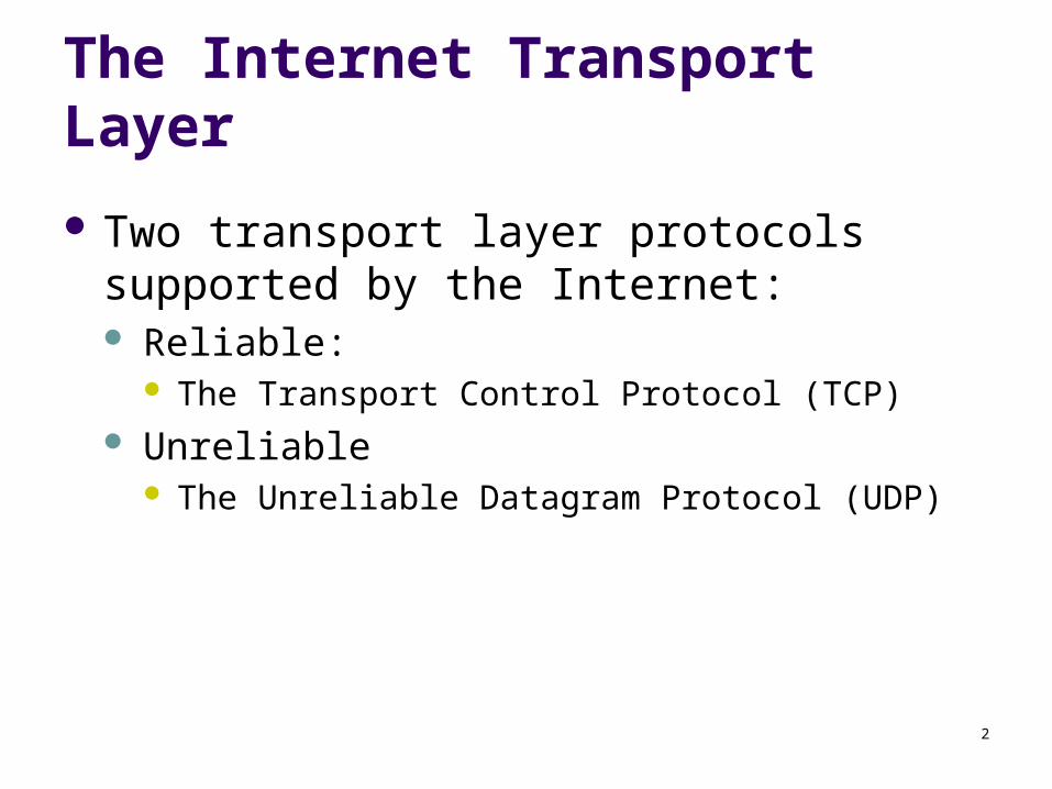
The Internet Transport Layer
Two transport layer protocols supported by the Internet: Reliable:
The Transport Control Protocol (TCP) Unreliable
The Unreliable Datagram Protocol (UDP)

3
UDP
UDP is an unreliable transport protocol that can be used in the Internet
UDP does not provide: connection management flow or error control guaranteed in-order packet delivery
UDP is almost a “null” transport layer

4
Why UDP?
No connection needs to be set up Throughput may be higher because UDP packets
are easier to process, especially at the source The user doesn’t care if the data is transmitted
reliably The user wants to implement his or her own
transport protocol
5
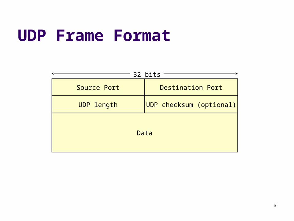
UDP Frame Format
32 bits
Source Port Destination Port
UDP length UDP checksum (optional)
Data
6
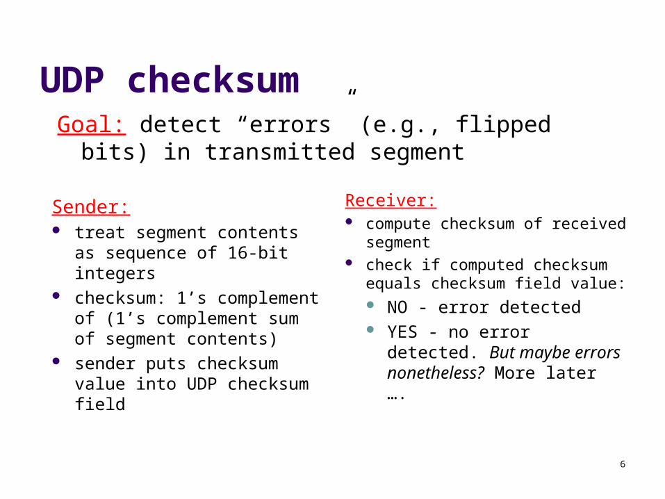
UDP checksum
Sender: treat segment contents as
sequence of 16-bit integers checksum: 1’s complement
of (1’s complement sum of segment contents)
sender puts checksum value into UDP checksum field
Receiver: compute checksum of received
segment check if computed checksum
equals checksum field value: NO - error detected YES - no error detected.
But maybe errors nonetheless? More later ….
Goal: detect “errors” (e.g., flipped bits) in transmitted segment
7
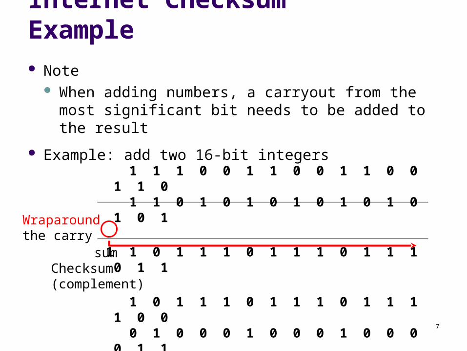
Internet Checksum Example Note
When adding numbers, a carryout from the most significant bit needs to be added to the result
Example: add two 16-bit integers1 1 1 1 0 0 1 1 0 0 1 1 0 0 1 1 01 1 1 0 1 0 1 0 1 0 1 0 1 0 1 0 1
1 1 0 1 1 1 0 1 1 1 0 1 1 1 0 1 1
1 1 0 1 1 1 0 1 1 1 0 1 1 1 1 0 01 0 1 0 0 0 1 0 0 0 1 0 0 0 0 1 1
Wraparoundthe carry
sumChecksum (complement)

8
TCP
TCP provides the end-to-end reliable connection that IP alone cannot support
The protocol Frame format Connection management Retransmission Flow control Congestion control
9
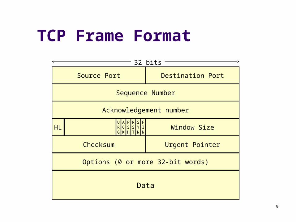
TCP Frame Format
Sequence Number
Acknowledgement number
Options (0 or more 32-bit words)
Checksum Urgent Pointer
Window SizeHLFIN
SYN
RST
PSH
ACK
URG
Data
32 bits
Source Port Destination Port

10
TCP Frame Fields
Source & Destination Ports 16 bit port identifiers for each packet
Sequence number The packet’s unique sequence ID
Acknowledgement number The sequence number of the next packet expected by the
receiver
11
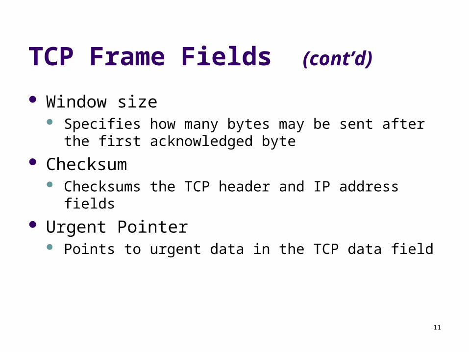
TCP Frame Fields (cont’d)
Window size Specifies how many bytes may be sent after the first
acknowledged byte
Checksum Checksums the TCP header and IP address fields
Urgent Pointer Points to urgent data in the TCP data field
12
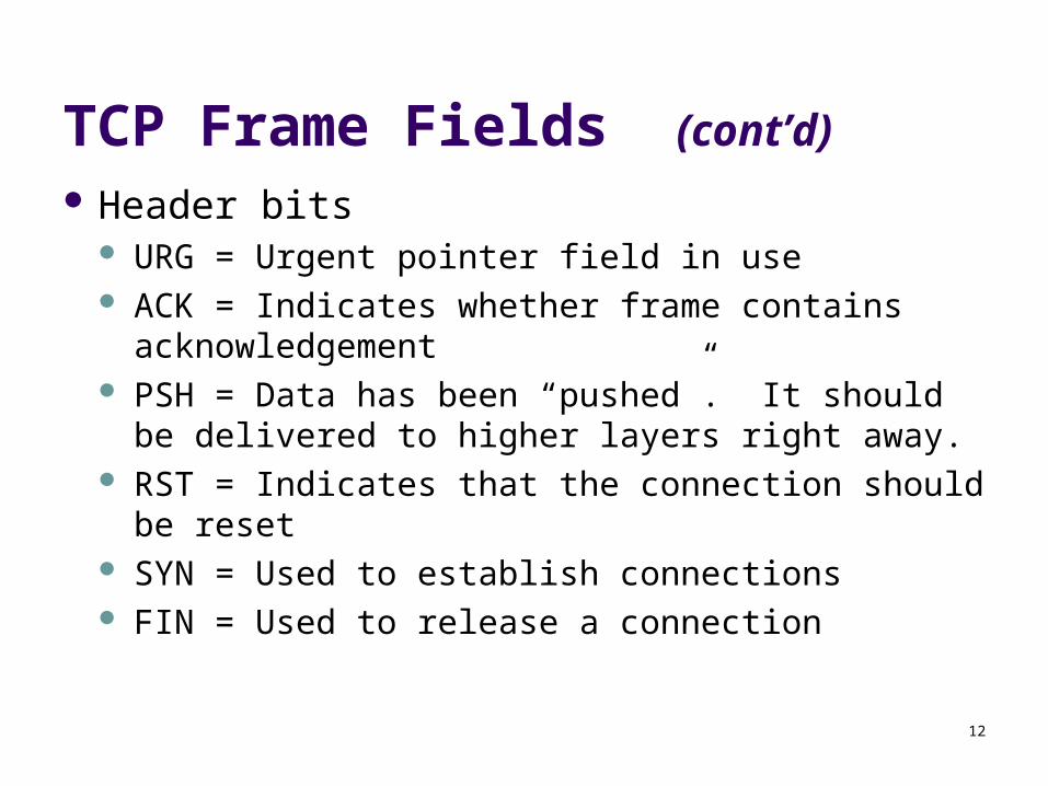
TCP Frame Fields (cont’d) Header bits
URG = Urgent pointer field in use ACK = Indicates whether frame contains
acknowledgement PSH = Data has been “pushed”. It should be
delivered to higher layers right away. RST = Indicates that the connection should be reset SYN = Used to establish connections FIN = Used to release a connection
13
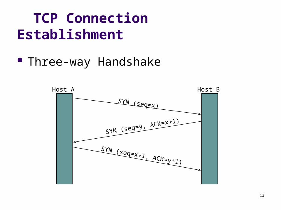
TCP Connection Establishment
Three-way Handshake
SYN (seq=x)
SYN (seq=y, ACK=x+1)
SYN (seq=x+1, ACK=y+1)
Host A Host B

14
TCP Connection Tear-down
Two double handshakes:
FIN (seq=x)
ACK (ACK=x+1)
ACK (ACK=y+1)
Host A Host B
FIN (seq=y)A->B
torn down
B->Atorn down
15
TCP Retransmission
When a packet remains unacknowledged for a period of time, TCP assumes it is lost and retransmits it
TCP tries to calculate the round trip time (RTT) for a packet and its acknowledgement
From the RTT, TCP can guess how long it should wait before timing out
16
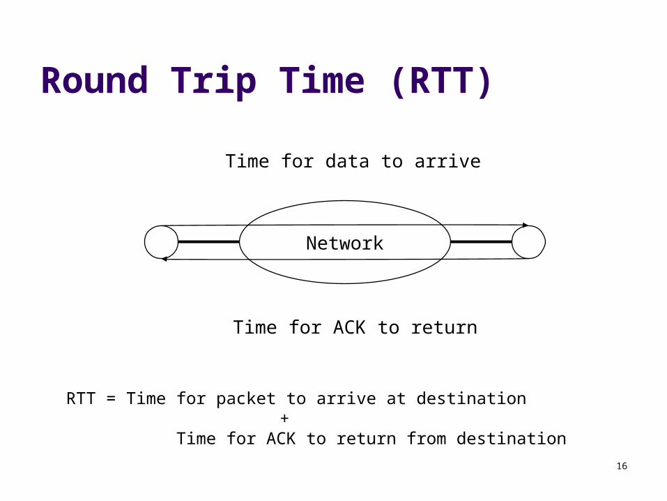
Round Trip Time (RTT)
RTT = Time for packet to arrive at destination +
Time for ACK to return from destination
Network
Time for data to arrive
Time for ACK to return
17
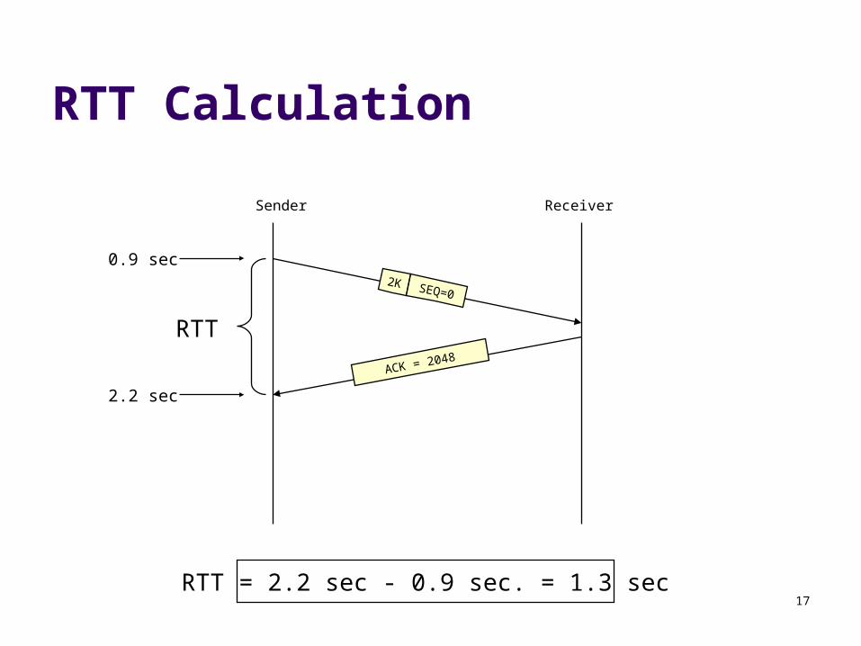
RTT Calculation
2K SEQ=0
ACK = 2048
ReceiverSender
RTT
0.9 sec
2.2 sec
RTT = 2.2 sec - 0.9 sec. = 1.3 sec
18
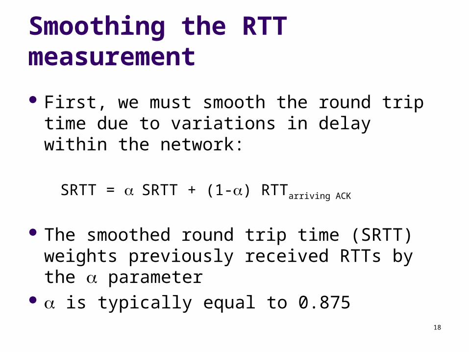
Smoothing the RTT measurement
First, we must smooth the round trip time due to variations in delay within the network:
SRTT = SRTT + (1-) RTTarriving ACK
The smoothed round trip time (SRTT) weights previously received RTTs by the parameter
is typically equal to 0.875
19
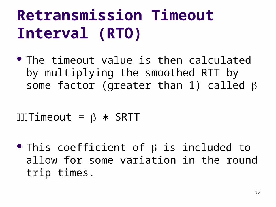
Retransmission Timeout Interval (RTO)
The timeout value is then calculated by multiplying the smoothed RTT by some factor (greater than 1) called
Timeout = SRTT
This coefficient of is included to allow for some variation in the round trip times.
20
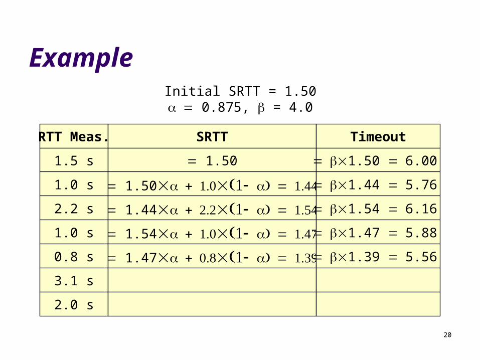
ExampleInitial SRTT = 1.50 0.875, = 4.0
RTT Meas. SRTT
1.5 s 1.50
1.0 s 1.50
2.2 s 1.44
1.0 s 1.54
0.8 s 1.47
3.1 s
Timeout
1.50 6.00
1.44 5.76
1.54 6.16
1.47 5.88
1.39 5.56
2.0 s
21
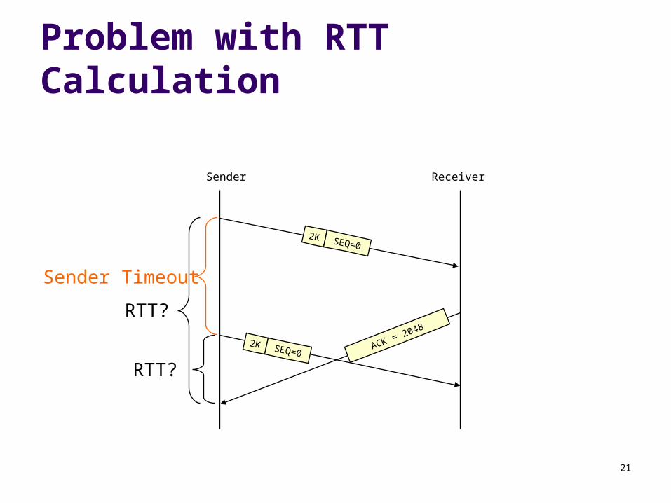
Problem with RTT Calculation
2K SEQ=0
ReceiverSender
Sender Timeout
2K SEQ=0
RTT?
RTT?
ACK = 2048
22
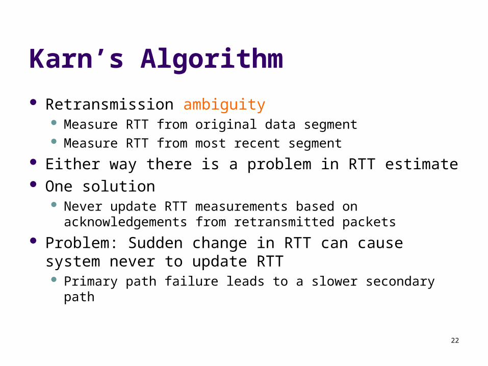
Karn’s Algorithm
Retransmission ambiguity Measure RTT from original data segment Measure RTT from most recent segment
Either way there is a problem in RTT estimate One solution
Never update RTT measurements based on acknowledgements from retransmitted packets
Problem: Sudden change in RTT can cause system never to update RTT
Primary path failure leads to a slower secondary path
23
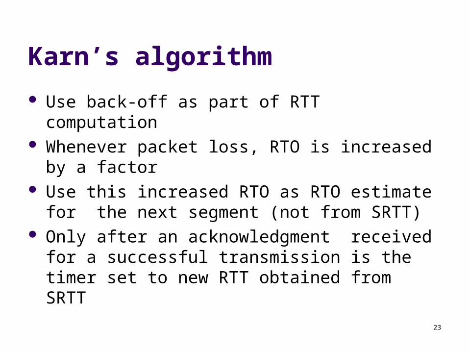
Karn’s algorithm
Use back-off as part of RTT computation Whenever packet loss, RTO is increased by a factor Use this increased RTO as RTO estimate for the
next segment (not from SRTT) Only after an acknowledgment received for a
successful transmission is the timer set to new RTT obtained from SRTT

24
Another Problem with RTT Calculation
RTT measurements can sometimes fluctuate severely
smoothed RTT (SRTT) is not a good reflection of round-trip time in these cases
Solution: Use Jacobson/Karels algorithm:
Error =RTT - SRTT
SRTT =SRTT + ErrorDev =Dev + h(|Error| - Dev)
Timeout = SRTT+ Dev
25
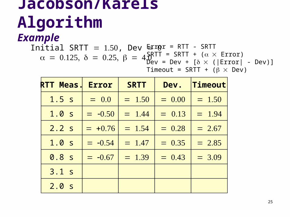
Jacobson/Karels AlgorithmExample
Initial SRTT , Dev
RTT Meas. SRTT
1.5 s
1.0 s
2.2 s
1.0 s
0.8 s
3.1 s
Error
Dev.
Timeout
Error = RTT - SRTTSRTT = SRTT + ( Error)Dev = Dev + [ (|Error| - Dev)]Timeout = SRTT + ( Dev)
2.0 s
26
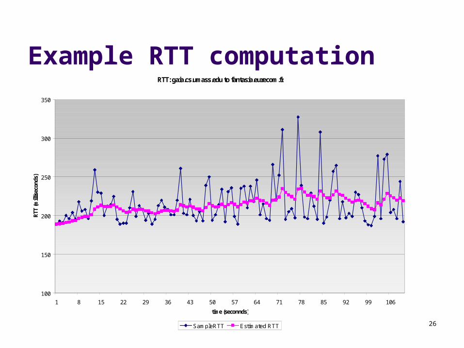
Example RTT computationRTT: gaia.cs.umass.edu to fantasia.eurecom.fr
100
150
200
250
300
350
1 8 15 22 29 36 43 50 57 64 71 78 85 92 99 106
time (seconnds)
RTT
(mill
isec
onds
)
SampleRTT Estimated RTT
27
TCP Flow Control
TCP uses a modified version of the sliding window
In acknowledgements, TCP uses the “Window size” field to tell the sender how many bytes it may transmit
TCP uses bytes, not packets, as sequence numbers
28
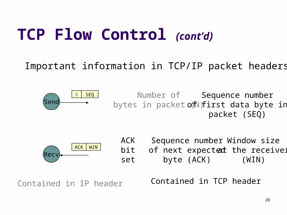
TCP Flow Control (cont’d)
SendNumber of
bytes in packet (N)Sequence numberof first data byte in
packet (SEQ)
N SEQ
Recv
Window sizeat the receiver
(WIN)
ACK WINSequence numberof next expected
byte (ACK)
Important information in TCP/IP packet headers
ACK bitset
Contained in IP header Contained in TCP header

29
Example TCP session
(1)remus:$ tcpdump -S host scullyKernel filter, protocol ALL, datagram packet sockettcpdump: listening on all devices
15:15:22.152339 eth0 > remus.4706 > scully.echo: S 1264296504:1264296504(0) win 32120 <mss 1460,sack OK,timestamp 71253512 0,nop,wscale 0> 15:15:22.153865 eth0 < scully.echo > remus.4706: S 875676030:875676030(0) ack 1264296505 win 8760 <mss 1460>15:15:22.153912 eth0 > remus.4706 > scully.echo: . 1264296505:1264296505(0) ack 875676031 win 32120
remus: telnet scully 7
A <return>
A
30
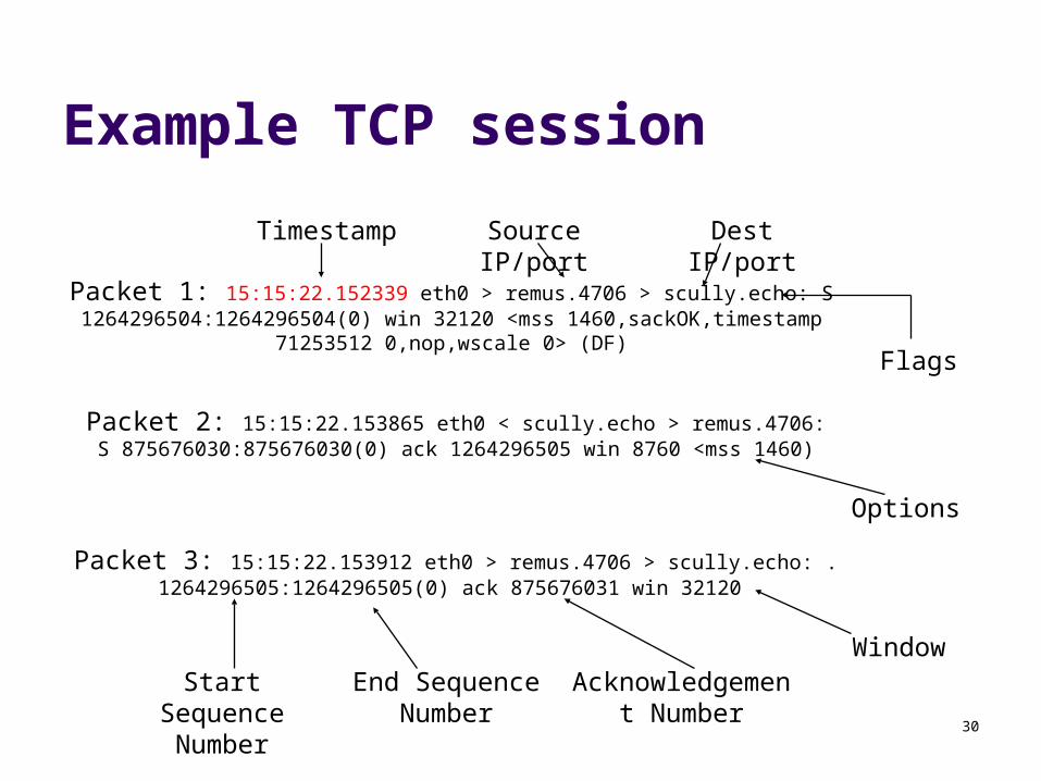
Example TCP session
Packet 1: 15:15:22.152339 eth0 > remus.4706 > scully.echo: S 1264296504:1264296504(0) win 32120 <mss 1460,sackOK,timestamp
71253512 0,nop,wscale 0> (DF)
Packet 2: 15:15:22.153865 eth0 < scully.echo > remus.4706: S 875676030:875676030(0) ack 1264296505 win 8760 <mss 1460)
Packet 3: 15:15:22.153912 eth0 > remus.4706 > scully.echo: . 1264296505:1264296505(0) ack 875676031 win 32120
Timestamp Source IP/port Dest IP/port
Flags
Options
Start Sequence Number
Acknowledgement Number
WindowEnd Sequence
Number
31
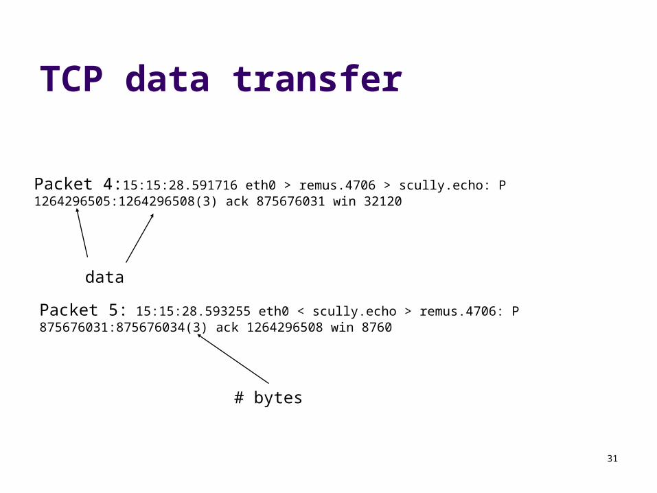
TCP data transfer
Packet 4:15:15:28.591716 eth0 > remus.4706 > scully.echo: P 1264296505:1264296508(3) ack 875676031 win 32120
Packet 5: 15:15:28.593255 eth0 < scully.echo > remus.4706: P 875676031:875676034(3) ack 1264296508 win 8760
data
# bytes

32
TCP Flow Control (cont’d)
2K SEQ=0
ACK = 2048 WIN = 2048
2K SEQ=2048
ACK = 4096 WIN = 0
ACK = 4096 WIN = 2048
1K SEQ=4096
Applicationdoes a 2Kwrite
Applicationdoes a 3Kwrite
Sender isblocked
Sender maysend up to 2K
Empty
2K
Full
2K
2K1K
Applicationreads 2K
0 4K
Receiver’sbuffer
ReceiverSender
33
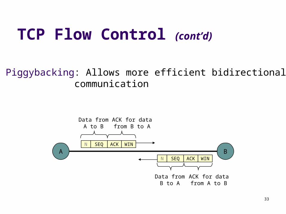
TCP Flow Control (cont’d)
AN SEQ
Piggybacking: Allows more efficient bidirectional communication
ACK WIN
BN SEQ ACK WIN
Data fromA to B
ACK for datafrom B to A
Data fromB to A
ACK for datafrom A to B
34
TCP Congestion Control
Recall: Network layer is responsible for congestion control
However, TCP/IP blurs the distinction In TCP/IP:
the network layer (IP) simply handles routing and packet forwarding
congestion control is done end-to-end by TCP
35
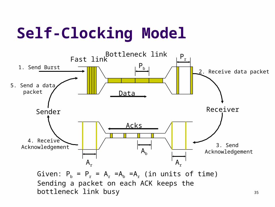
Self-Clocking Model
Sender Receiver
Fast linkBottleneck link
Data
Acks
1. Send Burst2. Receive data packet
3. Send Acknowledgement
4. Receive Acknowledgement
5. Send a data packet
Pb
Pr
Ar
Ab
Ar
Given: Pb = Pr = Ar =Ab =Ar (in units of time) Sending a packet on each ACK keeps the bottleneck link busy
36
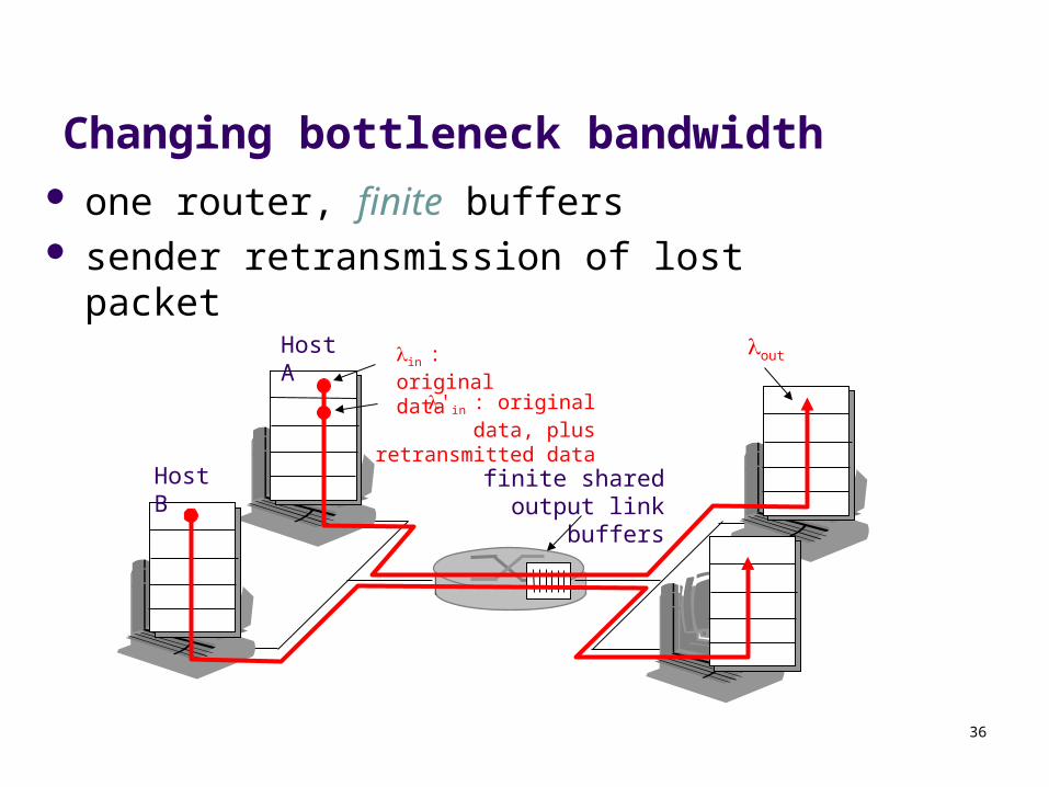
Changing bottleneck bandwidth one router, finite buffers sender retransmission of lost packet
finite shared output link buffers
Host A in : original data
Host B
out
'in : original data, plus retransmitted data
37
TCP Congestion Control
Goal: achieve self-clocking state Even if don’t know bandwidth of bottleneck Bottleneck may change over time
Two phases to keep bottleneck busy: Slow-start ramps up to the bottleneck limit
Packet loss signals we passed bandwidth of bottleneck
Congestion Avoidance tries to maintain self clocking mode once established

38
TCP Congestion Window
TCP introduces a second window, called the “congestion window”
This window maintains TCP’s best estimate of amount of outstanding data to allow in the network to achieve self-clocking
39
TCP Congestion Window
To determine how many bytes it may send, the sender takes the minimum of the receiver window and the congestion window
Example: If the receiver window says the sender can
transmit 8K, but the congestion window is only 4K, then the sender may only transmit 4K
If the congestion window is 8K but the receiver window says the sender can transmit 4K, then the sender may only transmit 4K
40
TCP Slow Start Phase
TCP defines the “maximum segment size” as the maximum size a TCP packet can be (including header)
TCP Slow Start: Congestion window starts small, at 1 segment size Each time a transmitted segment is acknowledged,
the congestion window is increased by one maximum segment size
On each ack, cwnd=cwnd +1
41
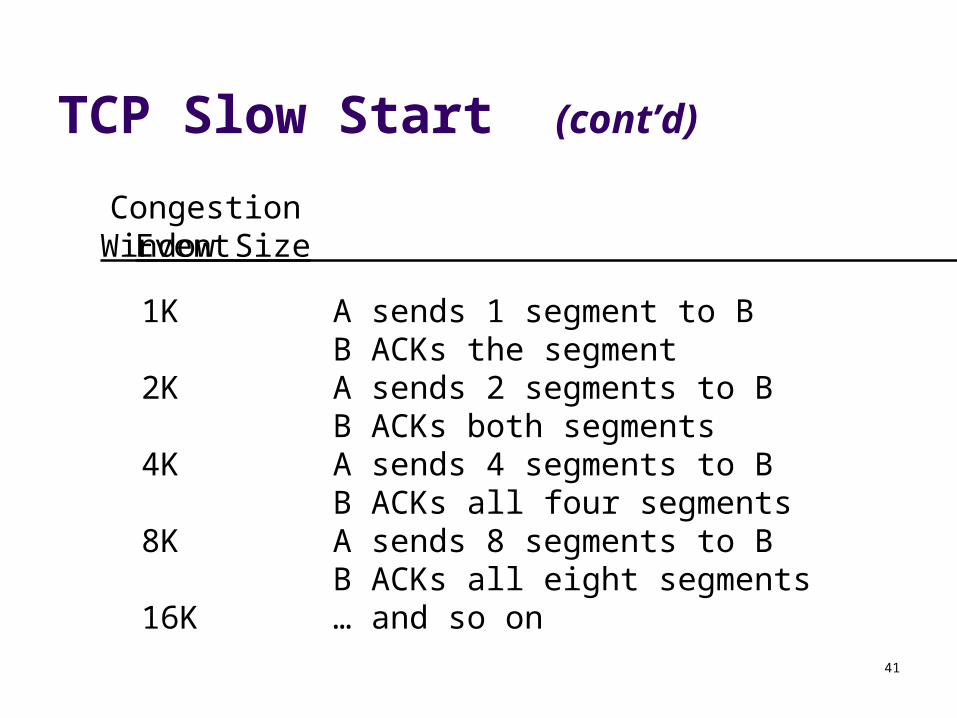
TCP Slow Start (cont’d)
1K A sends 1 segment to BB ACKs the segment
2K A sends 2 segments to BB ACKs both segments
4K A sends 4 segments to BB ACKs all four segments
8K A sends 8 segments to BB ACKs all eight segments
16K … and so on
CongestionWindow Size Event

42
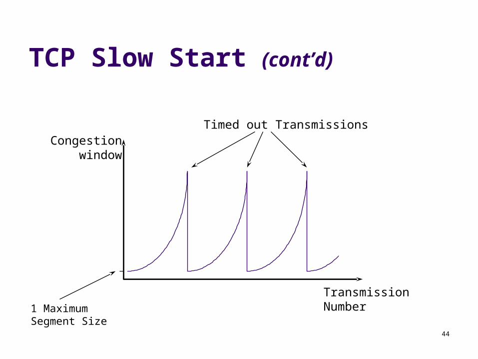
TCP Slow Start (cont’d)
Congestion window size grows exponentially (i.e. it keeps on doubling)
Packet losses indicate congestion Packet losses are determined by using timers at the
sender When a timeout occurs, the congestion window is
reduced to one maximum segment size and everything starts over
43
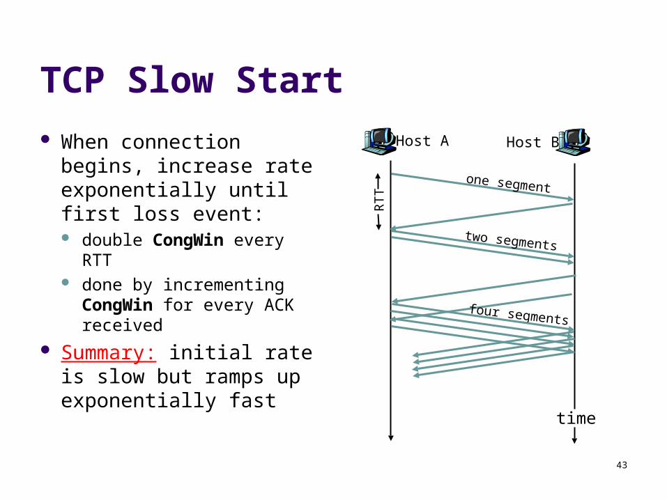
TCP Slow Start
When connection begins, increase rate exponentially until first loss event: double CongWin every
RTT done by incrementing
CongWin for every ACK received
Summary: initial rate is slow but ramps up exponentially fast
Host A
one segment
RTT
Host B
time
two segments
four segments
44
TCP Slow Start (cont’d)
Congestionwindow
TransmissionNumber
Timed out Transmissions
1 MaximumSegment Size
45
TCP Slow Start (cont’d)
TCP Slow Start by itself is inefficient Although the congestion window builds
exponentially, it drops to 1 segment size every time a packet times out
This leads to low throughput
46
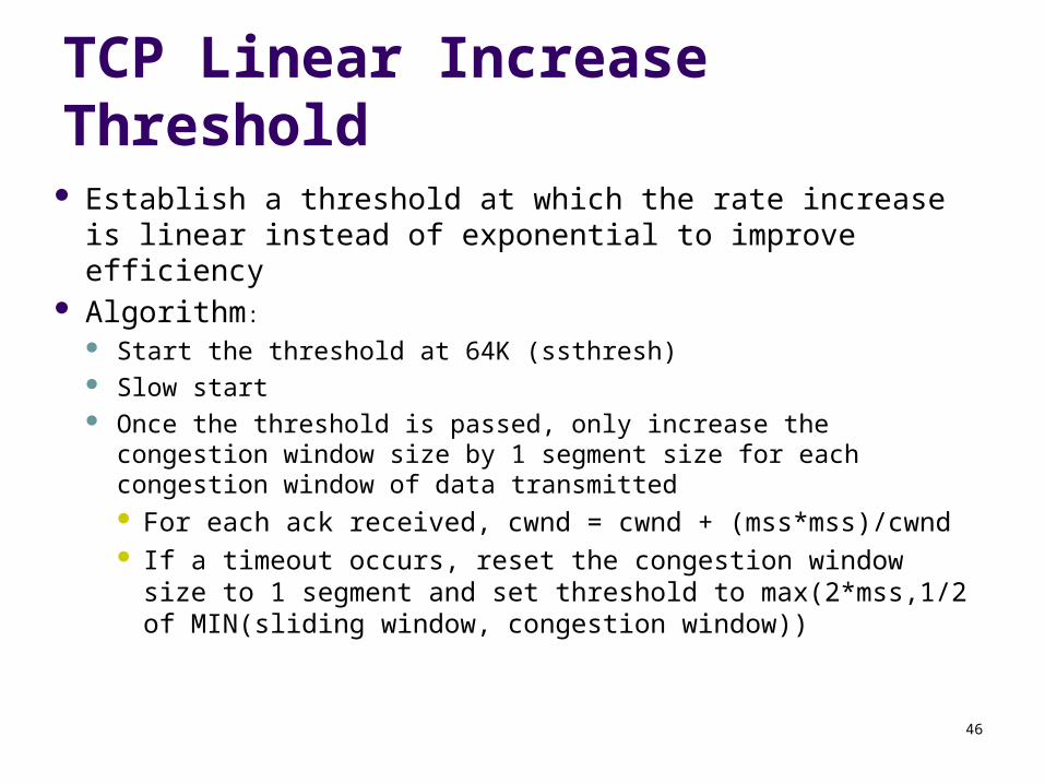
TCP Linear Increase Threshold Establish a threshold at which the rate increase is linear
instead of exponential to improve efficiency Algorithm:
Start the threshold at 64K (ssthresh) Slow start Once the threshold is passed, only increase the congestion
window size by 1 segment size for each congestion window of data transmitted For each ack received, cwnd = cwnd + (mss*mss)/cwnd If a timeout occurs, reset the congestion window size to 1
segment and set threshold to max(2*mss,1/2 of MIN(sliding window, congestion window))
47
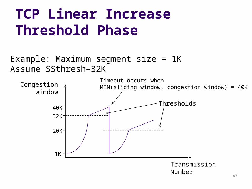
TCP Linear Increase Threshold Phase
Congestionwindow
TransmissionNumber
1K
20K
32K
Timeout occurs whenMIN(sliding window, congestion window) = 40K
Example: Maximum segment size = 1KAssume SSthresh=32K
Thresholds40K

48
TCP Fast Retransmit
Another enhancement to TCP congestion control Idea: When sender sees 3 duplicate ACKs, it
assumes something went wrong The packet is immediately retransmitted instead of
waiting for it to timeout Why?
Note that acks sent by the receiver when it receives a packet
Dup ack implies something is getting through Better than time out

49
TCP Fast RetransmitExample
ReceiverSender
1K SEQ=2048
1K SEQ=3072
ACK = 2048 WIN = 30K1K SEQ=4096
ACK = 2048 WIN = 31K
ACK = 2048 WIN = 29K1K SEQ=5120
ACK = 2048 WIN = 28KFast Retransmit
occurs (2nd packet is nowretransmitted w/o waiting
for it to timeout)1K SEQ=2048
ACK = 7168 WIN = 26K
MSS = 1K
1K SEQ=6144
ACK = 2048 WIN = 27K
Duplicate ACK #1
Duplicate ACK #2
Duplicate ACK #3
ACK of new data
50
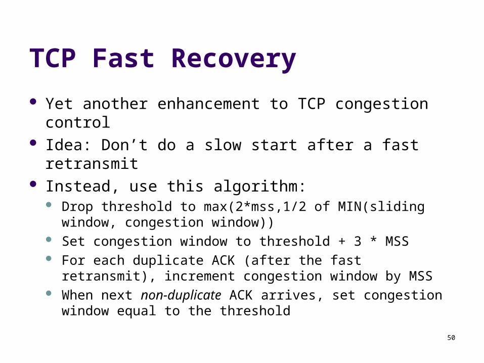
TCP Fast Recovery
Yet another enhancement to TCP congestion control
Idea: Don’t do a slow start after a fast retransmit Instead, use this algorithm:
Drop threshold to max(2*mss,1/2 of MIN(sliding window, congestion window))
Set congestion window to threshold + 3 * MSS For each duplicate ACK (after the fast retransmit),
increment congestion window by MSS When next non-duplicate ACK arrives, set congestion
window equal to the threshold
51
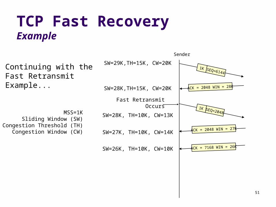
TCP Fast RecoveryExample
Sender
1K SEQ=2048
ACK = 7168 WIN = 26K
Fast RetransmitOccurs
ACK = 2048 WIN = 27K
ACK = 2048 WIN = 28K
1K SEQ=6144
SW=29K,TH=15K, CW=20KContinuing with theFast RetransmitExample... SW=28K,TH=15K, CW=20K
SW=28K, TH=10K, CW=13K
SW=27K, TH=10K, CW=14K
SW=26K, TH=10K, CW=10K
MSS=1KSliding Window (SW)
Congestion Threshold (TH)Congestion Window (CW)
52
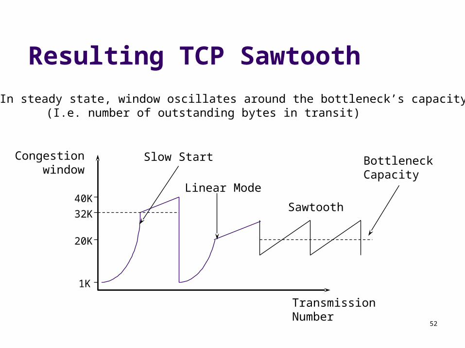
Resulting TCP Sawtooth
Congestionwindow
TransmissionNumber
1K
20K
32K
Slow Start
40KLinear Mode
Bottleneck Capacity
In steady state, window oscillates around the bottleneck’s capacity(I.e. number of outstanding bytes in transit)
Sawtooth
53
TCP Recap
Timeout Computation Timeout is a function of 2 values
the weighted average of sampled RTTs The sampled variance of each RTT
Congestion control: Goal: Keep the self-clocking pipe full in spite of changing
network conditions 3 key Variables:
Sliding window (Receiver flow control) Congestion window (Sender flow control) Threshold (Sender’s slow start vs. linear mode line)

54
TCP Recap (cont)
Slow start Add 1 segment for each ACK to the congestion
window -Double’s the congestion window’s volume each RTT
Linear mode (Congestion Avoidance) Add 1 segment’s worth of data to each congestion
window Adds 1 segment per RTT

55
Algorithm Summary: TCP Congestion Control When CongWin is below Threshold, sender in slow-start
phase, window grows exponentially.
When CongWin is above Threshold, sender is in congestion-avoidance phase, window grows linearly.
When a triple duplicate ACK occurs, Threshold set to max(FlightSize/2,2*mss) and CongWin set to Threshold+3*mss. (Fast retransmit, Fast recovery)
When timeout occurs, Threshold set to max(FlightSize/2,2*mss) and CongWin is set to 1 MSS.
FlightSize: The amount of data that has been sent but not yet acknowledged.
56
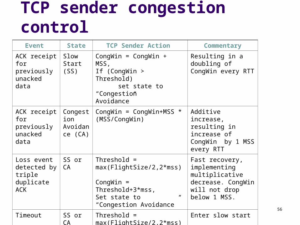
TCP sender congestion controlEvent State TCP Sender Action Commentary
ACK receipt for previously unacked data
Slow Start (SS)
CongWin = CongWin + MSS, If (CongWin > Threshold) set state to “Congestion Avoidance”
Resulting in a doubling of CongWin every RTT
ACK receipt for previously unacked data
CongestionAvoidance (CA)
CongWin = CongWin+MSS * (MSS/CongWin)
Additive increase, resulting in increase of CongWin by 1 MSS every RTT
Loss event detected by triple duplicate ACK
SS or CA Threshold = max(FlightSize/2,2*mss) CongWin = Threshold+3*mss,Set state to “Congestion Avoidance”
Fast recovery, implementing multiplicative decrease. CongWin will not drop below 1 MSS.
Timeout SS or CA Threshold = max(FlightSize/2,2*mss), CongWin = 1 MSS,Set state to “Slow Start”
Enter slow start
Duplicate ACK SS or CA Increment duplicate ACK count for segment being acked
CongWin and Threshold not changed

57
Fairness goal: if K TCP sessions share same bottleneck link of bandwidth R, each should have average rate of R/K
TCP connection 1
bottleneckrouter
capacity R
TCP connection 2
TCP Fairness
58
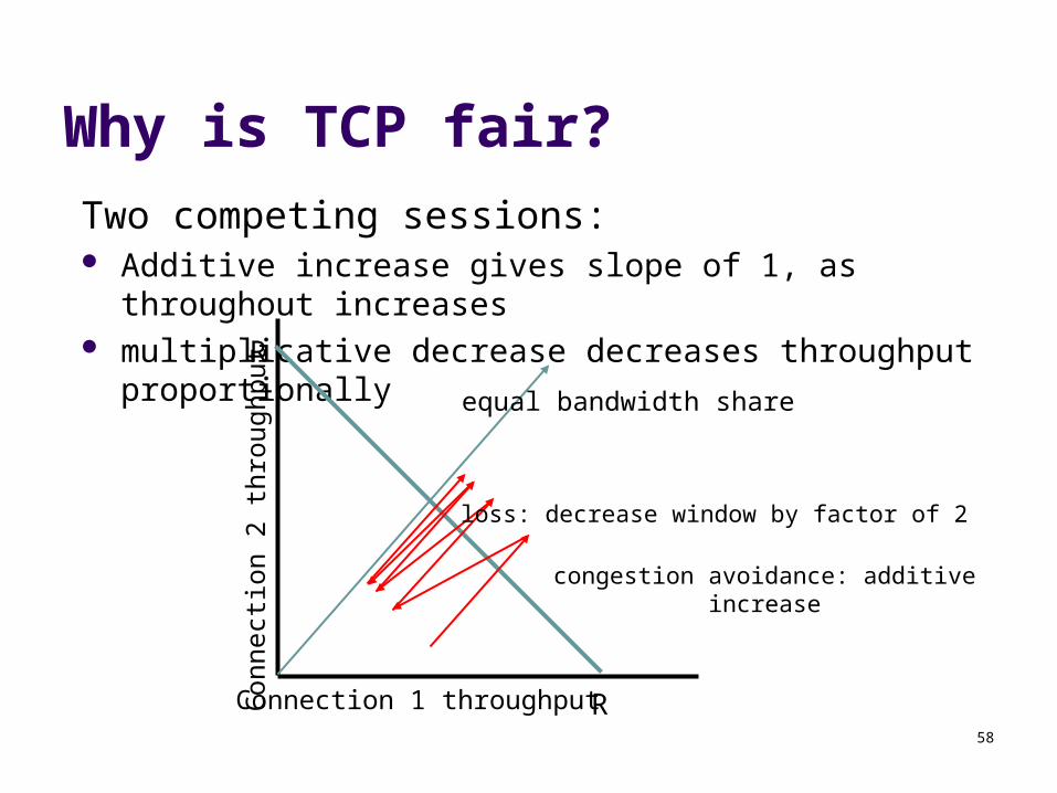
Why is TCP fair?
Two competing sessions: Additive increase gives slope of 1, as throughout increases multiplicative decrease decreases throughput proportionally
R
R
equal bandwidth share
Connection 1 throughputConnect
ion 2
th
roughput
congestion avoidance: additive increase
loss: decrease window by factor of 2
59
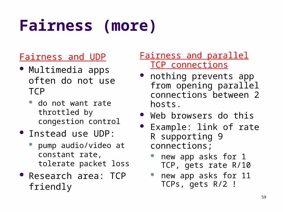
Fairness (more)
Fairness and UDP Multimedia apps often
do not use TCP do not want rate
throttled by congestion control
Instead use UDP: pump audio/video at
constant rate, tolerate packet loss
Research area: TCP friendly
Fairness and parallel TCP connections
nothing prevents app from opening parallel connections between 2 hosts.
Web browsers do this Example: link of rate R
supporting 9 connections; new app asks for 1 TCP, gets
rate R/10 new app asks for 11 TCPs,
gets R/2 !
60
Delay modelingQ: How long does it take to
receive an object from a Web server after sending a request?
Ignoring congestion, delay is influenced by:
TCP connection establishment
data transmission delay slow start
Notation, assumptions: Assume one link between client
and server of rate R S: MSS (bits) O: object size (bits) no retransmissions (no loss, no
corruption)
Window size: First assume: fixed congestion
window, W segments Then dynamic window, modeling
slow start
61
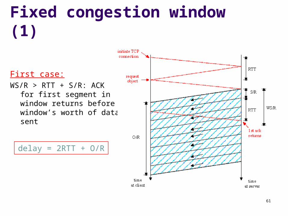
Fixed congestion window (1)
First case:WS/R > RTT + S/R: ACK for
first segment in window returns before window’s worth of data sent
delay = 2RTT + O/R
62
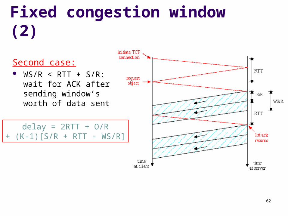
Fixed congestion window (2)
Second case: WS/R < RTT + S/R: wait
for ACK after sending window’s worth of data sent
delay = 2RTT + O/R+ (K-1)[S/R + RTT - WS/R]
63
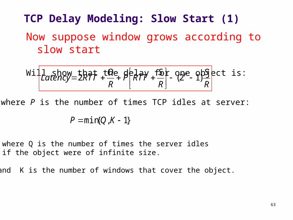
TCP Delay Modeling: Slow Start (1)
Now suppose window grows according to slow start
Will show that the delay for one object is:
R
S
R
SRTTP
R
ORTTLatency P )12(2
where P is the number of times TCP idles at server:
}1,{min KQP
- where Q is the number of times the server idles if the object were of infinite size.
- and K is the number of windows that cover the object.
64
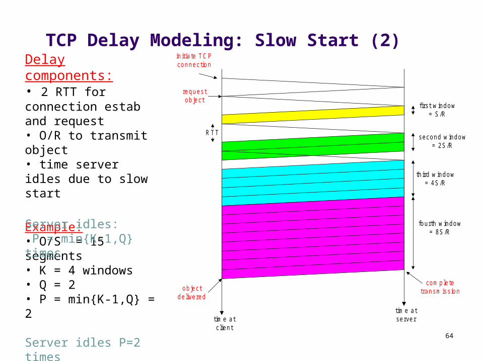
TCP Delay Modeling: Slow Start (2)
RTT
initia te TCPconnection
requestobject
first w indow= S /R
second w indow= 2S /R
third w indow= 4S /R
fourth w indow= 8S /R
com pletetransm issionobject
delivered
tim e atc lient
tim e atserver
Example:• O/S = 15 segments• K = 4 windows• Q = 2• P = min{K-1,Q} = 2
Server idles P=2 times
Delay components:• 2 RTT for connection estab and request• O/R to transmit object• time server idles due to slow start
Server idles: P = min{K-1,Q} times
65
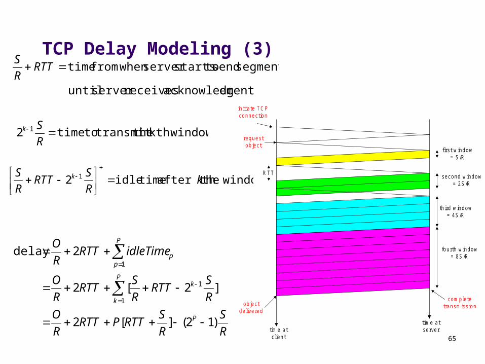
TCP Delay Modeling (3)
R
S
R
SRTTPRTT
R
O
R
SRTT
R
SRTT
R
O
idleTimeRTTR
O
P
kP
k
P
pp
)12(][2
]2[2
2delay
1
1
1
th window after the timeidle 2 1 kR
SRTT
R
S k
ementacknowledg receivesserver until
segment send tostartsserver whenfrom time RTTR
S
window kth the transmit totime2 1
R
Sk
RTT
initia te TCPconnection
requestobject
first w indow= S /R
second w indow= 2S /R
third w indow= 4S /R
fourth w indow= 8S /R
com pletetransm issionobject
delivered
tim e atc lient
tim e atserver
66
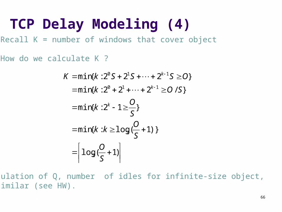
TCP Delay Modeling (4)
)1(log
)}1(log:{min
}12:{min
}/222:{min
}222:{min
2
2
110
110
S
OS
Okk
S
Ok
SOk
OSSSkK
k
k
k
Calculation of Q, number of idles for infinite-size object,is similar (see HW).
Recall K = number of windows that cover object
How do we calculate K ?
![€TCP/UDP Port Numberspsanchez/Distro_2012... · 19 tcp, udp chargen Character Generator; alias=ttytst source 20 tcp, udp ftp-data File Transfer [Default Data] 21 tcp, udp ftp File](https://static.fdocuments.us/doc/165x107/5e9f0261f4657916937549bf/atcpudp-port-psanchezdistro2012-19-tcp-udp-chargen-character-generator.jpg)