TCOM, L.P. DOCUMENT NO Electronic...TCOM, L.P. MANUFACTURING PROCESS SPECIFICATION DOCUMENT NO:...
24
TCOM, L.P. MANUFACTURING PROCESS SPECIFICATION DOCUMENT NO: PS10052 ISSUE DATE: October 29, 2010 TITLE: ELECTRONIC ASSEMBLY INTERNAL WIRING GUIDELINES FOR INSTALLATION AND INSPECTION PREPARED BY: David Mulholland PAGE 1 OF 24 SIGNATURE APPROVAL Glenn Cooper TCOM Headquarters Electronics Manufacturing Supervisor Jim Palmer TCOM Headquarters Manager of Electrical Engineering Design Ed Cunningham TCOM Headquarters Manager of Electrical/Electronic Packaging Design Jacques Leitao TCOM Headquarters Electronics Manufacturing Engineer George Kauffman TCOM Headquarters Senior Quality Engineer REVISIONS REV DATE DESCRIPTION APPROVAL PRE 07SEP10 Preliminary/Trial Release. D. Mulholland – 29OCT10 Production Release D. Mulholland
Transcript of TCOM, L.P. DOCUMENT NO Electronic...TCOM, L.P. MANUFACTURING PROCESS SPECIFICATION DOCUMENT NO:...
TCOM, L.P. MANUFACTURING PROCESS SPECIFICATION
DOCUMENT NO: PS10052 ISSUE DATE:
October 29, 2010
TITLE: ELECTRONIC ASSEMBLY INTERNAL WIRING GUIDELINES FOR INSTALLATION AND INSPECTION PREPARED BY: David Mulholland PAGE 1 OF 24 SIGNATURE APPROVAL Glenn Cooper TCOM Headquarters Electronics Manufacturing Supervisor
Jim Palmer TCOM Headquarters Manager of Electrical Engineering Design Ed Cunningham TCOM Headquarters Manager of Electrical/Electronic Packaging Design Jacques Leitao TCOM Headquarters Electronics Manufacturing Engineer George Kauffman TCOM Headquarters Senior Quality Engineer
REVISIONS
REV
DATE
DESCRIPTION APPROVAL
PRE 07SEP10 Preliminary/Trial Release. D. Mulholland – 29OCT10 Production Release D. Mulholland

TCOM PS10052 Rev – Page 2 of 24 Printed on 10/29/2010 10:17 AM
Table of Contents Purpose ........................................................................................................................................ 3 Scope ........................................................................................................................................... 3 Order of Precedence .................................................................................................................... 4 Tools, Equipment and Consumable Supplies ............................................................................... 4 Equipment and Consumable Supplies .......................................................................................... 4
Soldering Iron Calibration .......................................................................................................... 4 Crimp Tool Calibration .............................................................................................................. 5
References ................................................................................................................................... 5 References ................................................................................................................................... 5
Required Workstation References ............................................................................................ 5 Planning for Electronic Assembly Operations ............................................................................... 6
Manufacturing Orders (Production Travelers) ........................................................................... 6 Purchase Orders (Hardware or A&W Services) ........................................................................ 6
Qualification .................................................................................................................................. 6 TCOM Assembler Qualification Requirements .......................................................................... 6
Soldering ............................................................................................................................... 6 ESD Control ........................................................................................................................... 7 FOD Control .......................................................................................................................... 7
Supplier (Hardware and A&W Services) Qualification Requirements ....................................... 7 Process ......................................................................................................................................... 8 Guidelines Not On Drawings ........................................................................................................ 9
Protecting Wires from Rough Surfaces ..................................................................................... 9 Fill ALL Connector Pin Locations/Insulate ............................................................................... 10 Through-Hole Chaffing Protection ........................................................................................... 10 Torque ALL (Used and Unused) Terminal Block Screws ........................................................ 11 Wiring Arrangement (Use of Harnesses) ................................................................................ 12 Required/Permitted Wire Slack ............................................................................................... 12 Wiring (Harness) Protection/Support ....................................................................................... 13 Splices Generally Prohibited ................................................................................................... 14 Adhesive Mounting Installation – Cleaning and Dwell Time .................................................... 15
Inspectors and Inspections ......................................................................................................... 16 When to Inspect ...................................................................................................................... 16 Class 2 of IPC for Inspection Criteria ...................................................................................... 16 Inspector Training and Qualification ........................................................................................ 16 Use of Checklists .................................................................................................................... 16
Appendix I – W101C Workmanship Standard ............................................................................ 18 Appendix II – W101D Workmanship Standard ........................................................................... 19 Appendix III – W101E Workmanship Standard ........................................................................... 20 Appendix IV – W101G Workmanship Standard .......................................................................... 21 Appendix V – W101H Workmanship Standard ........................................................................... 22 Appendix VI – W101J Workmanship Standard ........................................................................... 23 Appendix VII – W101K Workmanship Standard ......................................................................... 24
TCOM PS10052 Rev – Page 3 of 24 Printed on 10/29/2010 10:17 AM
1. Purpose
1.1. To provide guidance for electronic and electrical assembly construction that:
1.1.1. Are considered routine manufacturing tasks whose details are left to the assembler (and so are not explicitly stated on TCOM design drawings).
1.1.2. Have, in the past, caused problems with equipment performance or
reliability when not properly accomplished.
1.2. To improve the integration and communication between TCOM Manufacturing and TCOM Suppliers for shared electronic assembly work.
1.3. To provide for Quality System Requirements in ISO 9000:2008 for Process Control, Calibration, Training, Continuous Improvement and Corrective/Preventive Action as they apply to Electronics Manufacturing.
2. Scope
2.1. This Process Specification applies: 2.1.1. To intra-enclosure portions of all TCOM’s deliverable air and ground
electronic and electrical assemblies (within assembly boundaries and not between separate enclosures).
2.1.2. At all TCOM, L.P. facilities and TCOM-operated portions of Field Sites. 2.1.3. At TCOM Suppliers doing “A & W” (assembly and wiring) work on TCOM
kitted parts or providing completed assemblies that include electrical/electronic component soldering or wiring on TCOM purchase orders. TCOM’s Planner and Buyer will send this PS with requests for quote and purchase orders for electronic assemblies.
2.2. This process specification does NOT apply to and need NOT be provided with
purchase orders to TCOM suppliers providing: 2.2.1. Commercial Off-The-Shelf (COTS) items [non-TCOM part numbers].
2.2.2. Military Off-The-Shelf (MOTS) items [non-TCOM part numbers that are, for
example, National Stock Numbers (NSNs)].
TCOM PS10052 Rev – Page 4 of 24 Printed on 10/29/2010 10:17 AM
2.2.3. Supplier-designed items which are the Supplier’s own part and are simply configuration-controlled by TCOM under:
2.2.3.1. A “Source Control Drawing” [TCOM part number that identifies
only the approved supplier, their item and some critical interface details].
2.2.3.2. An “Altered Item Drawing” [TCOM part number that tells how to modify a particular supplier’s part for a TCOM application].
3. Order of Precedence
3.1. The following take precedence in order:
3.1.1. Notes or graphics in TCOM’s purchase order, drawing, specification, schematic and wiring list for the part or assembly (equally since all should be consistent).
3.1.2. J-STD-001, IPC-A-610 and IPC-A-620 (as they may bear on the task or
technique required).
3.1.3. This Process Specification you are reading. 4. Tools, Equipment and Consumable Supplies.
4.1. Only parts called out on the Bill of Materials or those in this Process Specification may be included in manufactured electrical/electronic items.
4.1.1. Parts required for assemblies shall be kitted by TCOM Materials
Management for in-house or for partially subcontracted A&W assembly labor at a supplier.
4.1.2. Parts for wholly-subcontracted assemblies are the responsibility of the supplier.
4.1.3. Consumables (tie wraps, adhesive mounts, solder, flux, etc.) are not
generally kitted and are the responsibility of the builder. 4.2. For Electronic Assemblies built under J-STD-001/IPC-A-610 (but not for pure IPC-
A-620 Harness work only) soldering irons shall be managed as if calibrated and shall be periodically checked: 4.2.1. Cold – for Tip Ohms to Ground (for ESD protection).
4.2.2. Hot – for:
4.2.2.1. Temperature (for performance).
TCOM PS10052 Rev – Page 5 of 24 Printed on 10/29/2010 10:17 AM
4.2.2.2. Tip Voltage to Ground (for EOS). 4.3. Crimping tools shall be managed as if calibrated and shall be periodically checked
for: 4.3.1. crimp dimensions (detects tool wear or bad technique).
4.3.2. Crimp electrical resistance (Ohms for electrical integrity).
4.3.3. pull strength (LBF for mechanical integrity).
5. References.
5.1. As applicable to the work performed, effective revisions of the following documents must be present in the electrical/electronic assembly area and accessible to supervisors, assemblers and inspectors:
5.1.1. This Process Specification. 5.1.2. The TCOM drawing and any TCOM specification, schematic or wire list
REF on the BOM for the assemblies and subassemblies being built. 5.1.3. J-STD-001, Requirements for Soldered Electrical and Electronics
Assemblies
5.1.4. IPC-A-610, Acceptability of Electronics Assemblies
5.1.5. IPC/WHMA-A-620, Requirements and Acceptance for Cable and Wire Harness Assemblies
5.2. The following references do NOT need to be available or consulted but serve as
sources of requirements/guidance: 5.2.1. ANSI/ESD STM13.1-2000, Standard Test Method for Measuring Electrical
Potential from – Electrical Soldering/De-soldering Hand Tools [www.esda.org]
5.2.2. MIL-HDBK-454, General Guidelines for Electronic Equipment [https://assist.daps.dla.mil/quicksearch/]
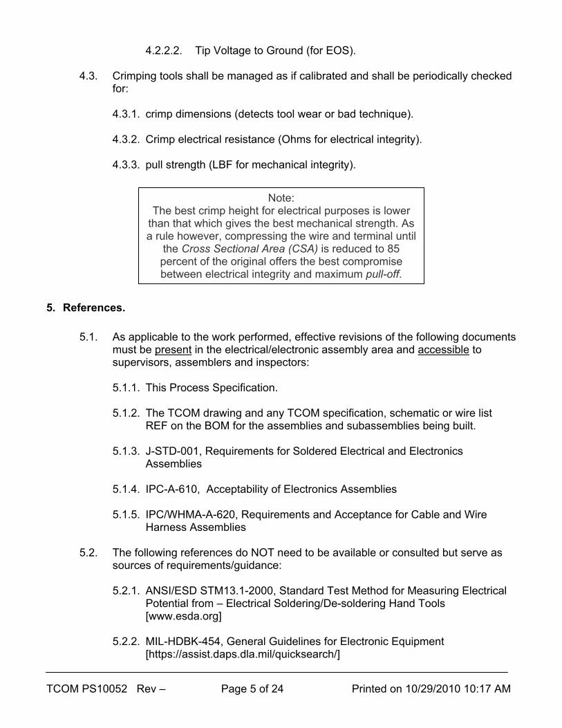
Note: The best crimp height for electrical purposes is lower
than that which gives the best mechanical strength. As a rule however, compressing the wire and terminal until
the Cross Sectional Area (CSA) is reduced to 85 percent of the original offers the best compromise between electrical integrity and maximum pull-off.
TCOM PS10052 Rev – Page 6 of 24 Printed on 10/29/2010 10:17 AM
5.2.3. TCOM (Westinghouse) ILSD 3.8.4 of 7/8/90 – Workmanship Standards
Manual:
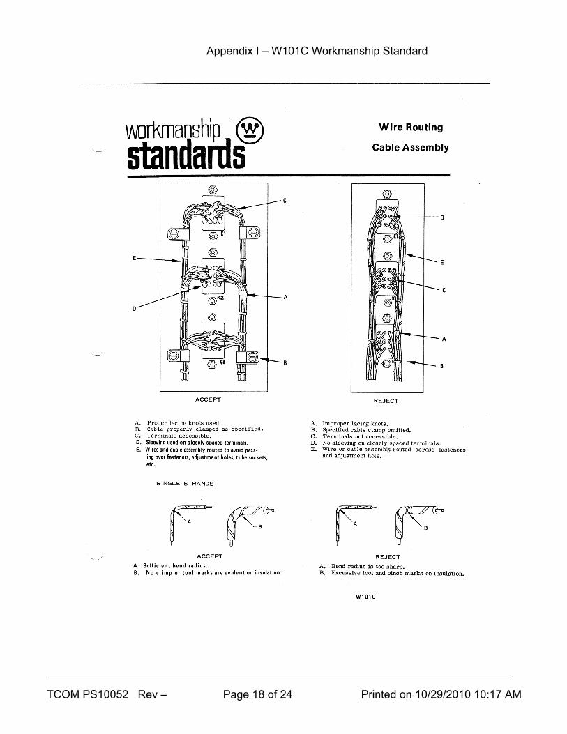
5.2.3.1. W101C: Wire Routing – Cable Assembly
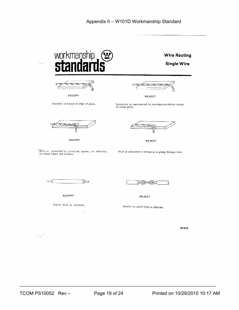
5.2.3.2. W101D: Wire Routing – Single Wire (and Splicing)
5.2.3.3. W101E: Cable Lacing
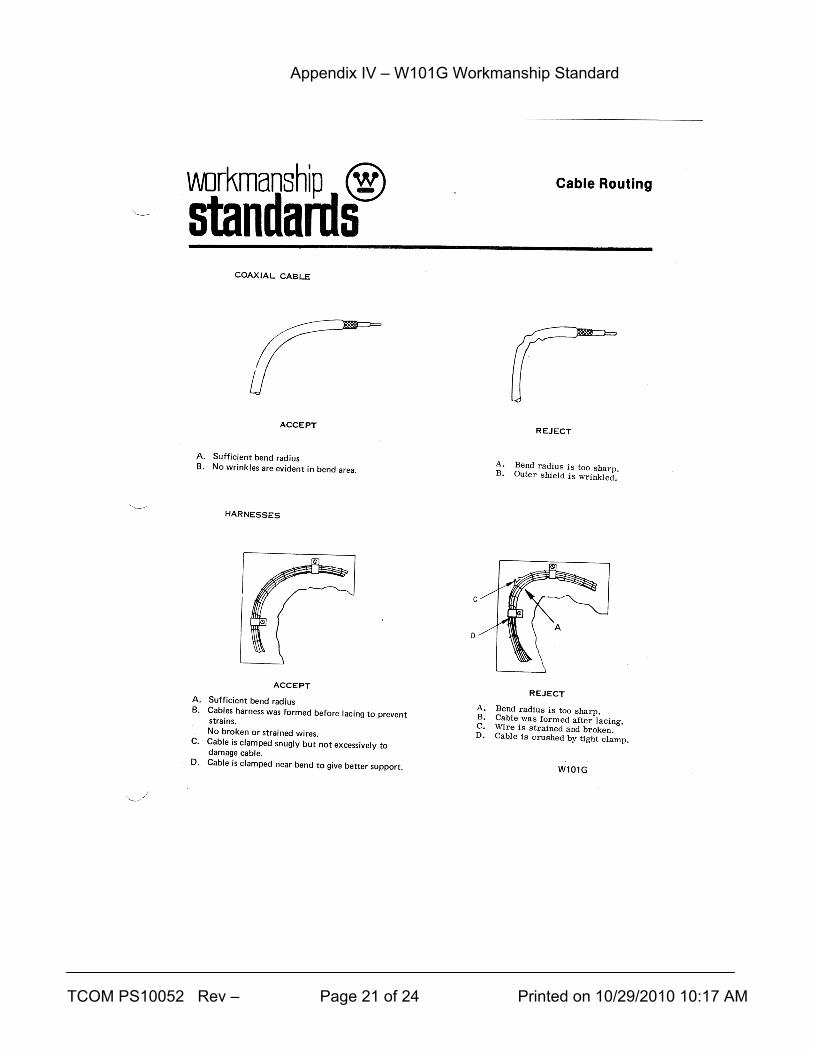
5.2.3.4. W101G: Cable Routing
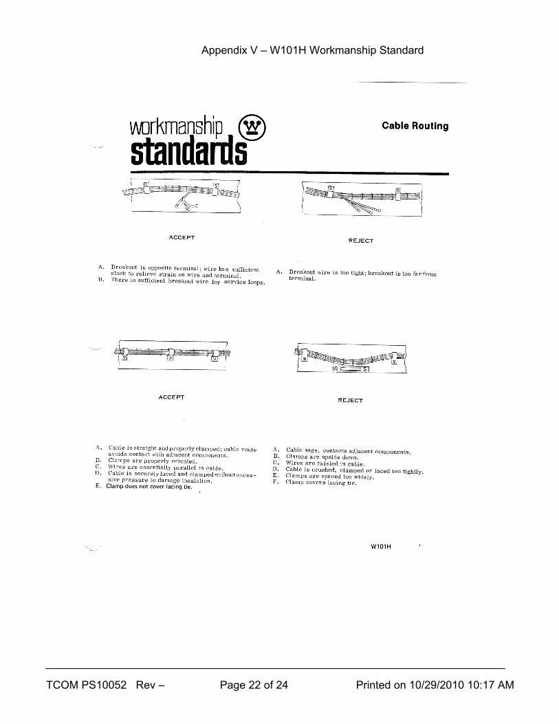
5.2.3.5. W101H: Cable Routing
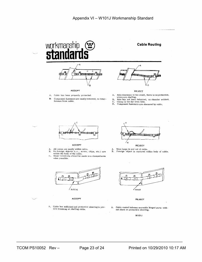
5.2.3.6. W101J: Cable Routing
5.2.3.7. W101K: Cable Routing
6. Planning for Electronic Assembly Operations. 6.1. Manufacturing Orders for in-house work shall contain adequate routing steps to
accomplish necessary work and inspections. [Supplier’s “travelers” or other work package control documents equivalent to TCOM MOs shall also have adequate definition of the work and inspections.]
6.2. Purchase orders shall have Quality Assurance codes and a technical data package appropriate to the complexity of the work and the degree of control required for the Program and the Supplier. [Supplier’s own purchase orders to sub-suppliers for subcontracted supplies and services shall flow down and control the work in a similar way.]
7. Qualification
7.1. TCOM personnel (including subcontractor labor at TCOM facilities/field sites) involved in manufacturing, repair or inspection of electrical and electronics shall have had the following minimum training: 7.1.1. For soldering:
7.1.1.1. a one-time J-STD-001 course.
7.1.1.2. an entry and bi-annual proficiency review by a TCOM Electronics
Manufacturing Supervisor or Quality Engineer (assemblers with continuous employment in soldering whose regular inspections show proficiency may not be required to solder a test piece).
TCOM PS10052 Rev – Page 7 of 24 Printed on 10/29/2010 10:17 AM
7.1.2. ESD training per TCOM’s ESD Control Plan.
7.1.3. FOD training per TCOM’s FOD Control Plan. 7.2. Suppliers of A&W services or complete electronics shall:
7.2.1. Have been audited at least once by TCOM Quality and TCOM
Manufacturing Engineering/Planning to ensure adequate conditions needed to accomplish acceptable quality work including: 7.2.1.1. Facility suitability. 7.2.1.2. Personnel training/qualifications. 7.2.1.3. Calibration of soldering/crimping tooling and measuring
instruments. 7.2.1.4. ESD control. 7.2.1.5. FOD control. 7.2.1.6. Quality Inspection system with non-conforming material control. 7.2.1.7. Presence of required technical references. 7.2.1.8. Ability to control configuration documents (files for TCOM
purchase orders and their drawings, specifications, schematics and wire lists).
7.2.1.9. When necessary (if parts are bought), ability to purchase, identify and control raw materials and parts used in electronic assemblies (including TCOM kits).
7.2.2. Maintain a satisfactory performance (cost, schedule and quality) and take timely and effective corrective/preventive actions to address problems – determination of acceptable performance will be made jointly by TCOM’s Manufacturing, Purchasing and Quality Managers.
TCOM PS10052 Rev – Page 8 of 24 Printed on 10/29/2010 10:17 AM
8. Process
8.1. Make sure you have the TCOM drawing (and any TCOM specification, schematic and wire list documents it requires). The revisions of these should match: 8.1.1. The TCOM Manufacturing Order (MO) if work is at a TCOM facility.
8.1.2. The TCOM Purchase Order (PO) if the work is at a Supplier’s facility.
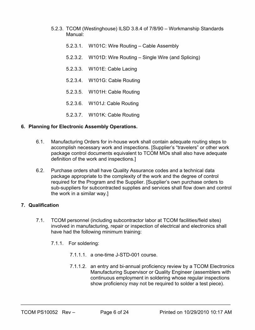
8.2. Establish a FOD-safe (for all work) and ESD-safe (for ESD sensitive components)
work area. ESD-sensitive components will be marked on packaging and the part; also, TCOM drawings for ESD-senitive work will be marked. A common marking is:
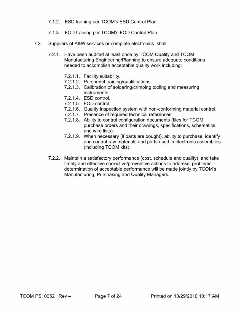
8.3. Check that all calibrated tooling (especially soldering irons, crimp tools and torque
tools and any multi-meter) are in calibration. A typical calibration sticker will look like the one below; the “NEXT CAL. DUE” date on any sticker will be after the date you do your work (i.e., in the future):
Note: for complex assemblies, child part
revision levels should also be checked to make sure the entire build is the
correct configuration.
TCOM PS10052 Rev – Page 9 of 24 Printed on 10/29/2010 10:17 AM
8.4. Check that all shelf-life items (Locktite®, O-rings, adhesive backed gaskets, etc.) are not expired.
8.5. Build to the TCOM drawings and documents first.
8.6. Consult section 9, below, of this Process Specification you are reading for
general guidance on items not normally on drawings. 8.7. Where the drawings and J-STD-001, IPC-A-610 and IPC-A-620 are silent, follow
this Process Specification you are reading.
8.8. For help with unexpected problems or if you are not sure what to do, contact your Supervisor (preferred) or Quality Assurance (also O.K.); suppliers who cannot resolve an issue internally should notify TCOM’s Buyer for assistance.
8.9. Examine/critique your own work when you are done; tell your Supervisor you are finished. Present completed work to Quality Assurance as directed by your Supervisor; shop traveler/MO routings should determine this.
8.10. Move the item to Unit Test only when directed by your supervisor.
8.11. Parts may not ship until a final quality assurance inspection is completed and any
deficiencies are corrected; portions of tests may need to be re-done to validate rework or repair of any problems found in final inspection.
9. General Guidelines Not Always On TCOM Drawings
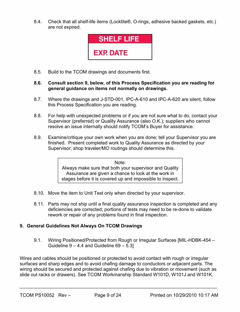
9.1. Wiring Positioned/Protected from Rough or Irregular Surfaces [MIL-HDBK-454 –
Guideline 9 – 4.4 and Guideline 69 – 5.3] Wires and cables should be positioned or protected to avoid contact with rough or irregular surfaces and sharp edges and to avoid chafing damage to conductors or adjacent parts. The wiring should be secured and protected against chafing due to vibration or movement (such as slide out racks or drawers). See TCOM Workmanship Standard W101D, W101J and W101K.
Note: Always make sure that both your supervisor and Quality
Assurance are given a chance to look at the work in stages before it is covered up and impossible to inspect.

TCOM PS10052 Rev – Page 10 of 24 Printed on 10/29/2010 10:17 AM
9.2. Fill All Connector Pin Locations/Added Insulation [MIL-HDBK-454 – Guideline 10 - 4.11.4 and Guideline 69 – 4.5]
All contact positions should be filled with contacts in MIL-STD connectors used in TCOM work (TCOM generally uses environmentally sealed connectors and the contacts are part of the sealing). This does NOT say all pins are actually wired (in fact, some spare pins are required on most connectors). Un-potted connectors furnished as integral wired in parts of articles of equipment should have a piece of insulating tubing placed over each wire in the connector. The tubing should be long enough to cover the contact and at least 12.5 mm of insulation of the wire attached to it; but in no case should the length of the tubing exceed 50 mm. The minimum length of 12.5 mm may be reduced to 4.5 mm where restricted volume does not permit longer tubing (such as in miniaturized electronic subassemblies). The tubing should fit tightly over the contact or be tied securely enough so that it will not slide off. If bare wire is used, the tubing should be long enough to extend at least 6 mm beyond the contact, metal shell or clamp, whichever projects the farthest. This section does not apply to connectors with body insulated crimp-on contacts.
9.3. Through-Hole (Chafing) Protection [MIL-HDBK-454 – Guideline 69 - 4.2]
When a wire is run through any hole in a piece of metal, the hole should have a grommet (or must be greater than 3mm thick and have a 1.5 mm or greater radius). If your hole seems sharp at all, stop and find out what it needs; if a suitable radius is not present, a grommet will need to be added to the BOM on the drawing (if there is none called out). See TCOM Workmanship Standard W101D.
TCOM PS10052 Rev – Page 11 of 24 Printed on 10/29/2010 10:17 AM
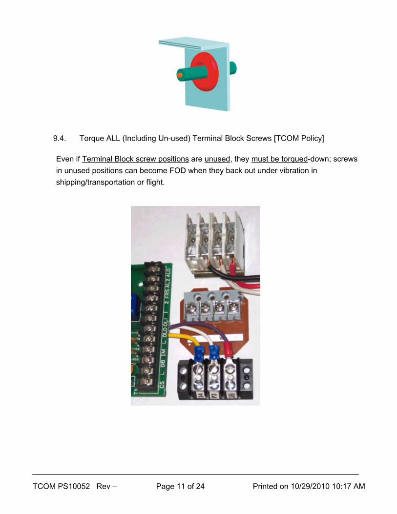
9.4. Torque ALL (Including Un-used) Terminal Block Screws [TCOM Policy]
Even if Terminal Block screw positions are unused, they must be torqued-down; screws in unused positions can become FOD when they back out under vibration in shipping/transportation or flight.
TCOM PS10052 Rev – Page 12 of 24 Printed on 10/29/2010 10:17 AM
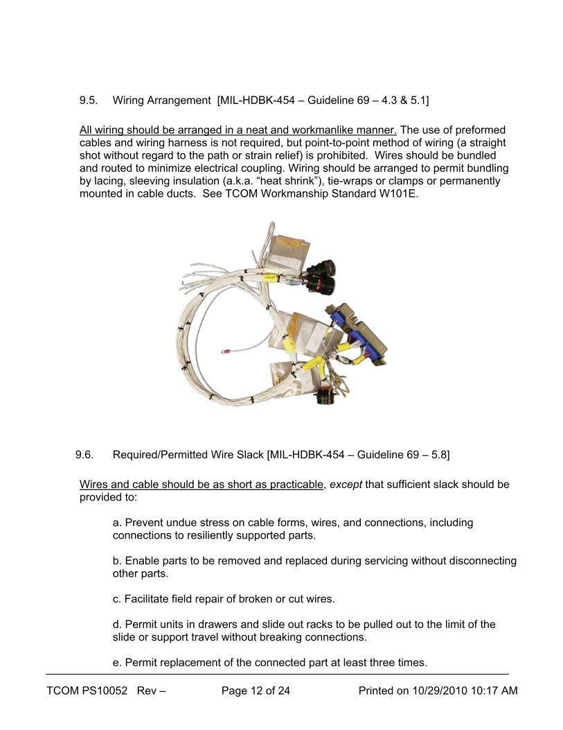
9.5. Wiring Arrangement [MIL-HDBK-454 – Guideline 69 – 4.3 & 5.1]
All wiring should be arranged in a neat and workmanlike manner. The use of preformed cables and wiring harness is not required, but point-to-point method of wiring (a straight shot without regard to the path or strain relief) is prohibited. Wires should be bundled and routed to minimize electrical coupling. Wiring should be arranged to permit bundling by lacing, sleeving insulation (a.k.a. “heat shrink”), tie-wraps or clamps or permanently mounted in cable ducts. See TCOM Workmanship Standard W101E.
9.6. Required/Permitted Wire Slack [MIL-HDBK-454 – Guideline 69 – 5.8]
Wires and cable should be as short as practicable, except that sufficient slack should be provided to:
a. Prevent undue stress on cable forms, wires, and connections, including connections to resiliently supported parts. b. Enable parts to be removed and replaced during servicing without disconnecting other parts. c. Facilitate field repair of broken or cut wires. d. Permit units in drawers and slide out racks to be pulled out to the limit of the slide or support travel without breaking connections. e. Permit replacement of the connected part at least three times.
TCOM PS10052 Rev – Page 13 of 24 Printed on 10/29/2010 10:17 AM
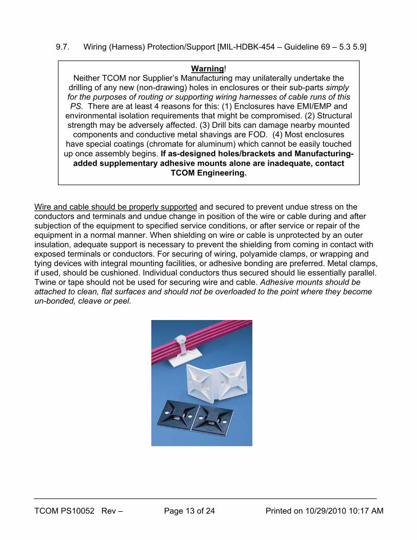
9.7. Wiring (Harness) Protection/Support [MIL-HDBK-454 – Guideline 69 – 5.3 5.9]
Wire and cable should be properly supported and secured to prevent undue stress on the conductors and terminals and undue change in position of the wire or cable during and after subjection of the equipment to specified service conditions, or after service or repair of the equipment in a normal manner. When shielding on wire or cable is unprotected by an outer insulation, adequate support is necessary to prevent the shielding from coming in contact with exposed terminals or conductors. For securing of wiring, polyamide clamps, or wrapping and tying devices with integral mounting facilities, or adhesive bonding are preferred. Metal clamps, if used, should be cushioned. Individual conductors thus secured should lie essentially parallel. Twine or tape should not be used for securing wire and cable. Adhesive mounts should be attached to clean, flat surfaces and should not be overloaded to the point where they become un-bonded, cleave or peel.
Warning! Neither TCOM nor Supplier’s Manufacturing may unilaterally undertake the
drilling of any new (non-drawing) holes in enclosures or their sub-parts simply for the purposes of routing or supporting wiring harnesses of cable runs of this PS. There are at least 4 reasons for this: (1) Enclosures have EMI/EMP and
environmental isolation requirements that might be compromised. (2) Structural strength may be adversely affected. (3) Drill bits can damage nearby mounted
components and conductive metal shavings are FOD. (4) Most enclosures have special coatings (chromate for aluminum) which cannot be easily touched up once assembly begins. If as-designed holes/brackets and Manufacturing-
added supplementary adhesive mounts alone are inadequate, contact TCOM Engineering.
TCOM PS10052 Rev – Page 14 of 24 Printed on 10/29/2010 10:17 AM
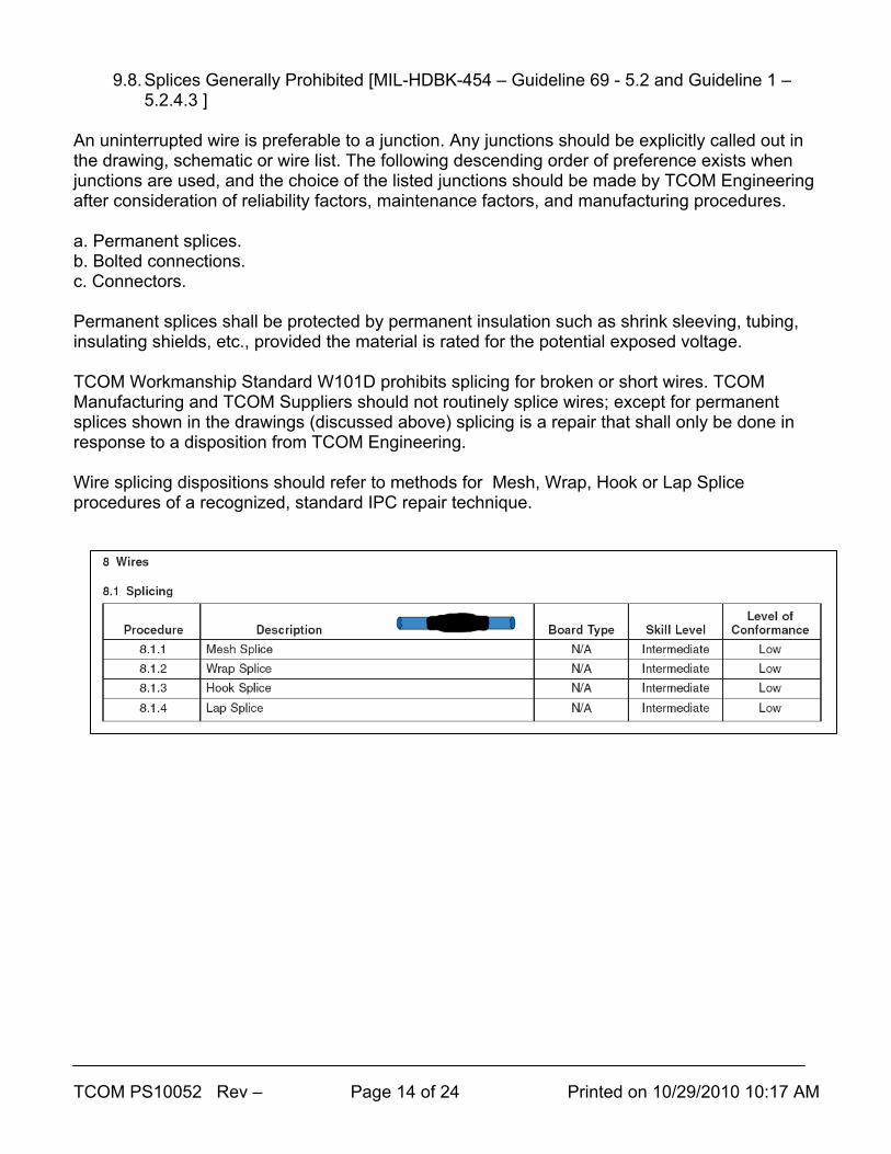
9.8. Splices Generally Prohibited [MIL-HDBK-454 – Guideline 69 - 5.2 and Guideline 1 – 5.2.4.3 ]
An uninterrupted wire is preferable to a junction. Any junctions should be explicitly called out in the drawing, schematic or wire list. The following descending order of preference exists when junctions are used, and the choice of the listed junctions should be made by TCOM Engineering after consideration of reliability factors, maintenance factors, and manufacturing procedures. a. Permanent splices. b. Bolted connections. c. Connectors. Permanent splices shall be protected by permanent insulation such as shrink sleeving, tubing, insulating shields, etc., provided the material is rated for the potential exposed voltage. TCOM Workmanship Standard W101D prohibits splicing for broken or short wires. TCOM Manufacturing and TCOM Suppliers should not routinely splice wires; except for permanent splices shown in the drawings (discussed above) splicing is a repair that shall only be done in response to a disposition from TCOM Engineering. Wire splicing dispositions should refer to methods for Mesh, Wrap, Hook or Lap Splice procedures of a recognized, standard IPC repair technique.

TCOM PS10052 Rev – Page 15 of 24 Printed on 10/29/2010 10:17 AM
9.9 Adhesive Mount Installation [Follow Manufacturer’s Guidelines]
Mounts need to be placed on clean surfaces and allowed to rest before they carry the load of a cable harness. For rubber and acrylic based foam tape adhesives mounts, isopropyl alcohol may be used for cleaning/degreasing on most surfaces of TCOM parts. The dwell time at no load for common, pressure-sensitive adhesive mounts is at least 2 hours but may be as long as 8 hours - follow the manufacturer's guidelines OR wait 8 hours. See typical directions below:
TCOM PS10052 Rev – Page 16 of 24 Printed on 10/29/2010 10:17 AM
10. Inspectors and Inspections
10.1. Except for unusual evolutions (such as audits), inspect assemblies at the following points in time: 10.1.1. At source (by TCOM at the Supplier’s facility) for purchased items ONLY
if the part is expensive, long lead time, high risk or cannot be effectively done at TCOM. Parts are coded for Source Inspection on the TCOM purchase order.
10.1.2. Incoming at TCOM QA receiving for purchased assemblies or Supplier-provided A&W Services on TCOM kits.
10.1.3. In-process (TCOM or Supplier) ONLY if required because some work will become un-viewable or un-testable when covered up by further assembly….and: 10.1.3.1. AFTER Manufacturing agrees the part is ready…and 10.1.3.2. BEFORE any Unit Test is performed.
10.1.4. After REWORK or REPAIR.
10.1.5. Final at TCOM before stocking, issue to a higher assembly or delivery.
10.2. Inspect to IPC Class 2 requirements at points in time where each sub-assembly
can be fully examined (this might be both in-process and final for complex, multi-layer assemblies).
10.3. Inspectors of the following work shall be qualified per this section:
10.3.1. Assemblies Inspectors – shall have had satisfactory IPC-A-610 training with test; re-test as required by the standard.
10.3.2. Harnesses Inspectors – shall have had satisfactory IPC-A-620 training
with test; re-test as required by the standard.
10.4. A locally-prepared Electronics Inspection Checklist (EIC) shall be maintained and used for inspections. 10.4.1. Suppliers shall deliver their EIC forms as “inspection records” per the
corresponding QA Code on the TCOM Purchase order. Incoming EIC Forms will be filed with the receipt traveler.
TCOM PS10052 Rev – Page 17 of 24 Printed on 10/29/2010 10:17 AM
10.4.2. At TCOM receiving inspection, the TCOM EIC form shall be used to inspect parts which arrive without a supplier form or with an inadequate (or less comprehensive) form. Deficiencies found get entered into the CaWeb Nonconformance Report (NR) database.
10.4.3. For in-house work at TCOM, the TCOM EIC Form shall be used to
perform in-process and final inspection work. Deficiencies found get entered into the CaWeb Manufacturing Order Discrepancy (MOD) database.
TCOM PS10052 Rev – Page 18 of 24 Printed on 10/29/2010 10:17 AM
Appendix I – W101C Workmanship Standard
TCOM PS10052 Rev – Page 19 of 24 Printed on 10/29/2010 10:17 AM
Appendix II – W101D Workmanship Standard

TCOM PS10052 Rev – Page 20 of 24 Printed on 10/29/2010 10:17 AM
Appendix III – W101E Workmanship Standard
TCOM PS10052 Rev – Page 21 of 24 Printed on 10/29/2010 10:17 AM
Appendix IV – W101G Workmanship Standard
TCOM PS10052 Rev – Page 22 of 24 Printed on 10/29/2010 10:17 AM
Appendix V – W101H Workmanship Standard
TCOM PS10052 Rev – Page 23 of 24 Printed on 10/29/2010 10:17 AM
Appendix VI – W101J Workmanship Standard
TCOM PS10052 Rev – Page 24 of 24 Printed on 10/29/2010 10:17 AM
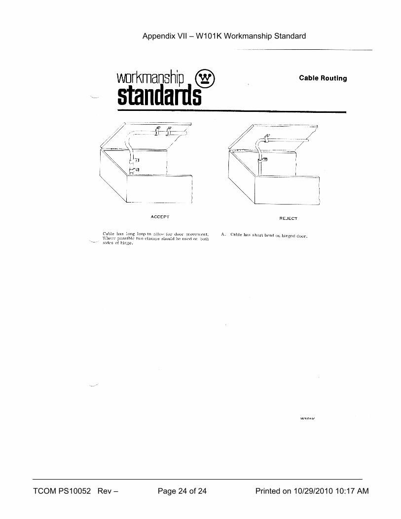
Appendix VII – W101K Workmanship Standard