TCI : 141, Rev
49
Transcript of TCI : 141, Rev


TCI : 141, Rev.12 Page 2 of 8
Sl. No. Description Requirement
1
Site Conditions :-
Altitude above MSL 50 metres
Ambient temperature 50° C
Relative Humidity 100 %
Atmosphere Tropical, dusty, salty, corrosive and highly polluted
2 Motor type Squirrel cage type induction motor suitable for direct on line starting through any type of breaker.
3 Applicable Standards IS-325, IS-1231, IS-6362, IS-2253, IS-5572, IS-12065, IS-12075, IS/IEC-60079, IS-12615, IS/IEC-60529 & IEC-60034. (Latest version of relevant standards shall be referred).
4 Application Light Fuel Oil (LFO), Heavy Fuel Oil (HFO), Drain Oil & Sump Oil - Pump motor.
5 Type of Enclosure and degree of protection
Totally Enclosed Fan Cooled (TEFC), IP-55 as per IEC- 60529
6 Flame proof enclosures
Flame proof, Ex - ‘d’ enclosures as per IS 2148/IEC-60079 shall be provided for the following applications, Light Fuel Oil (LFO), Heavy Fuel Oil (HFO), Drain Oil & Sump Oil - Pump motor – Flame proof motor. Area of Classification: Gas Group – II B with temperature class T4, Zone 2 as per IEC 60079.
7 Duty Cycle Continuous, S1
8 Energy Efficiency Class
IE-2/IE-3 as per IS-12615/IEC 60034-30. Refer project specific transmittal for applicable energy efficiency class.
9 Rated Voltage & Tolerance
415 V, AC, 3 Phase, ± 10 %.
10 Rated Frequency & Tolerance 50 Hz, ± 5 %
11 Combined voltage & frequency tolerance 10 % (absolute sum)

TCI : 141, Rev.12 Page 3 of 8
Sl. No. Description Requirement
12 General Requirements
a. All motors shall be so designed that maximum inrush
currents, locked rotor and pull out torque developed at extreme voltage and frequency variations do not endanger the motor and driven equipment.
b. Motor shall be designed to keep torsional and rotational
natural frequencies of vibration at least 25 percent above the motor rated speed ranges to avoid resonant vibration over the operating speed range of the motor and driven equipment.
c. Maximum continuous rating (MCR) of the motor shall have
at least 15 % margin over the maximum load demand of the driven equipment including voltage and frequency variation. (Applicable only if vendor supplies motor along with the driven equipment or load).
13 Torque requirements
Accelerating torque at any speed with the lowest permissible starting voltage shall be at least 10% of motor full load torque.
Pull Out torque at rated voltage shall not be less than 205 % of full load torque.
14 Requirements during Starting & Running
Motor shall start with rated load and accelerate to full speed
with 80 % rated voltage at motor terminals The motor shall be capable of withstanding the stresses
imposed if started at 110 % rated voltage. The motor shall be capable of operating satisfactorily at full
load for 5 minutes without injurious heating with 75 % rated voltage at motor terminals.
The motor shall be designed to withstand momentary over-load of 60% of full load torque for 15 seconds without any damage.
The motor shall be designed to withstand 120 % of rated speed for 2 minutes without any mechanical damage.

TCI : 141, Rev.12 Page 4 of 8
Sl. No. Description Requirement
15 Class of Insulation Class-F insulation with temperature rise limited to Class-B. Temperature rise of the motor shall be limited to 70° C (by resistance method) over an ambient temperature of 50° C.
16 Stress withstanding capability during Bus Transfer
The motor may be subjected to sudden application of 150 % rated voltage during bus transfer, due to the phase difference between the incoming voltage and motor residual voltage.
17 Capacity to restart for rated voltage
a. Two successive starts from cold condition
b. Three equally spread starts per hour
c. Two hot starts in succession, with motor initially running at normal temperature.
18 Starting Current The starting current (% of FLC) shall be limited as per the standard IS-12615.
19 Locked Rotor Condition
The ratio of Locked Rotor KVA at rated voltage to rated KW shall not exceed as indicated below (without any further tolerance) For Motor rating from 50 KW ≤ 110KW : 11
20 Locked Rotor with-stand time
For motor with starting time up to 20 seconds at minimum permissible voltage during starting, the locked rotor withstand time under hot condition at highest voltage limit shall be at least 2.5 seconds more than starting time.
For motor with starting time more than 20 seconds but not exceeding 45 seconds at minimum permissible voltage during starting, the locked rotor withstand time under hot condition at highest voltage limit shall be at least 5 seconds more than the starting time.
For motor with starting time more than 45 seconds at minimum permissible voltage during starting, the locked rotor withstand time under hot condition at highest voltage limit shall be 10% more than the starting time
Vendor to provide Speed switches mounted on the motor shaft in case the above requirement is not met with.

TCI : 141, Rev.12 Page 5 of 8
Sl. No. Description Requirement
21 Type of balancing of rotor Dynamic balancing
22 Method of cooling IC-0411 as per IS-6362
23 Direction of cooling air flow NDE side to DE Side
24 Winding wire
Enameled Copper Wire, Grade-2, as per IS-13730, Part-3. Windings shall be non-hygroscopic, oil resistant and flame resistant.
25 Treatment on Winding Insulation
Winding Insulation shall be given tropical and fungicidal treatment for operation of motor in hot, humid & tropical climate.
26 Noise level Noise level shall be limited to 85 dB at 1 metre distance.
27 Vibration level The peak amplitude of vibration shall be as per IS-12075 (Limits of Severity-Normal grade shall be followed).
28 Shaft extension Motor shall be provided with key slotted bare shaft extension, with key at the drive end.
29 Terminal box
The flame proof terminal box shall be provided as per IS/IEC-60079. The terminal box shall be capable of being turned through 360° in steps of 180° or 90°. Shall meet IP 55 protection class requirements as per IEC 60034-5. 1 No. Earth terminal shall be provided inside the terminal box. Minimum Distance between centre of the terminal stud & the gland plate and Minimum inter-phase/phase-earth air clearance shall be provided as per IEC standards. Terminal box shall have adequate space to terminate the Power cable applicable to the motor by using suitable lugs. Connection diagram shall be marked inside the terminal box.

TCI : 141, Rev.12 Page 6 of 8
Sl. No. Description Requirement
30 Cable Entries, Cable Glands & Lugs
Cable entries, Cable glands and Lugs shall be provided suitable for the power cable size as indicated in the annexure (project specific transmittal). Double Compression type, brass with nickel plated flame proof cable glands shall be provided – Quantity to be matched with the number of entries. 3 Nos. of Tinned Copper Lugs shall be provided.
31 Terminals Separate Terminals for Space heaters and Windings with suitable connecting links shall be supplied.
32 Body Earth Shall have 2 Nos. of earth points (Threaded hole with suitable GI Bolt) at appropriate location (in motor base frame).
33 Space heater for motors rated 30 KW and above
Separate space heater suitable for 240 V AC, Single Phase supply shall be provided.
34 Lifting device Eye bolt.
35 Project specific requirements
Vendor to take care of the project specific requirements indicated in the annexure - “Project specific transmittal”.
36 Name Plates Motor shall have name plate as per relevant IS and in addition, Manufacture’s name, frame size, Energy Efficiency class, Insulation class designation shall also be indicated.
37 Quality assurance, Inspection & Testing
Motors up to 30 KW, Inspection by Vendor meeting IEC standard requirements, as applicable. Routine & type test reports shall be submitted for review and acceptance by BHEL. For Motors >30 KW, Inspection by BHEL/Third party Inspection TPI agency as per BHEL approved VQP/RQP. Routine tests will be witnessed by BHEL/TPI. Type test reports shall be submitted for review and acceptance by BHEL. In case the vendor is not able to submit report of the type test(s) conducted within last 5 years from the date of bid opening, or in case the type test report(s) are not found to be meeting the specification requirements, the vendor shall conduct all such
TCI : 141, Rev.12 Page 7 of 8
Sl. No. Description Requirement
tests either in an independent laboratory or at manufacturer’s works in presence of Owner’s representative under this contract, free of cost to the Owner and submit the reports for approval.
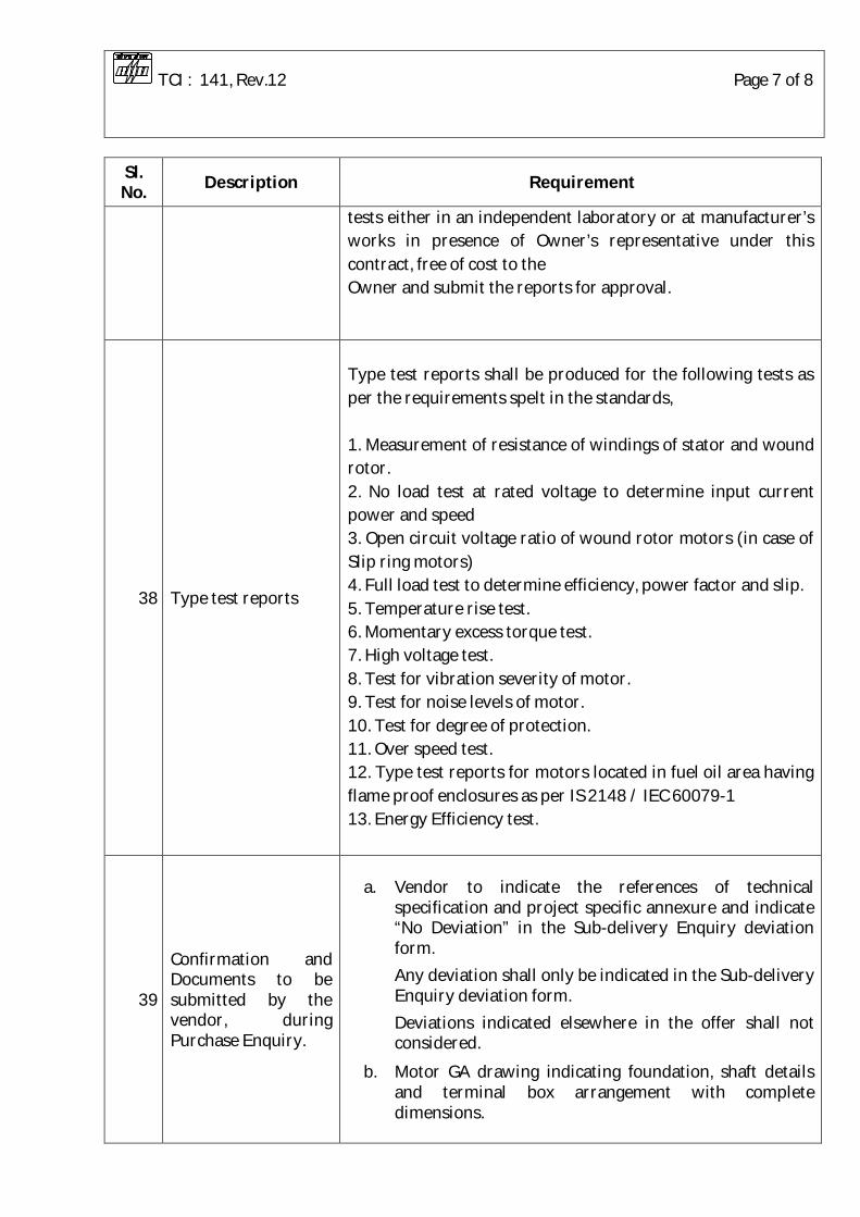
38 Type test reports
Type test reports shall be produced for the following tests as per the requirements spelt in the standards, 1. Measurement of resistance of windings of stator and wound rotor. 2. No load test at rated voltage to determine input current power and speed 3. Open circuit voltage ratio of wound rotor motors (in case of Slip ring motors) 4. Full load test to determine efficiency, power factor and slip. 5. Temperature rise test. 6. Momentary excess torque test. 7. High voltage test. 8. Test for vibration severity of motor. 9. Test for noise levels of motor. 10. Test for degree of protection. 11. Over speed test. 12. Type test reports for motors located in fuel oil area having flame proof enclosures as per IS 2148 / IEC 60079-1 13. Energy Efficiency test.
39
Confirmation and Documents to be submitted by the vendor, during Purchase Enquiry.
a. Vendor to indicate the references of technical specification and project specific annexure and indicate “No Deviation” in the Sub-delivery Enquiry deviation form.
Any deviation shall only be indicated in the Sub-delivery Enquiry deviation form.
Deviations indicated elsewhere in the offer shall not considered.
b. Motor GA drawing indicating foundation, shaft details and terminal box arrangement with complete dimensions.

TCI : 141, Rev.12 Page 8 of 8
Sl. No. Description Requirement
40
Documents to be submitted by the vendor for approval by BHEL/Customer, after placement of purchase order.
3 Sets of the following :-
a. Final technical Data sheet as per the format submitted by BHEL.
b. Motor GA drawing indicating foundation, shaft details and terminal box arrangement with complete dimensions.
c. Motor Characteristic curves (Torque Vs. Speed, Current Vs. Speed, Speed Vs. time, Current Vs. time, Efficiency and PF Vs. load, Thermal withstand characteristic)
d. O & M manuals.
41 Packing The packing shall be suitable for safe transport, safe delivery at site and shall avoid damages due to environmental conditions during storage at site.
42 Painting Paint shade shall be as per the purchase enquiry. The finish shall be corrosion resistant, epoxy based paint.
Specification for
Clean-Out Conveyor Drive With Gear Reducer
Spec. No.
GF-187/05
Page 1 /12
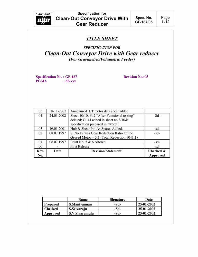
TITLE SHEET
SPECIFICATION FOR
Clean-Out Conveyor Drive with Gear reducer (For Gravimetric/Volumetric Feeder)
Specification No. : GF-187 Revision No.:05
PGMA : 65-xxx
05 18-11-2003 Annexure-I LT motor data sheet added
04 24.01.2002 Sheet 10/10, Pt.2 “After Functional testing”
deleted; Cl.3.I added in sheet no.3/10&
specification prepared in “word”.
-Sd-
03 16.01.2001 Hub & Shear Pin As Spares Added. -sd-
02 08.07.1997 Sl.No.12 was Gear Reduction Ratio Of the
Geared Motor = 5:1 (Total Reduction 1041:1)
-sd-
01 08.07.1997 Point No. 5 & 6 Altered. -sd-
00 - First Release -sd-
Rev.
No.
Date Revision Statement Checked &
Approved
Name Signature Date
Prepared S.Manivannan -Sd- 25-01-2002
Checked S.Selvaraju -Sd- 25-01-2002
Approved S.V.Sivaramulu -Sd- 25-01-2002

Specification for
Clean-Out Conveyor Drive With Gear Reducer
Spec. No.
GF-187/05
Page 2 /12
Scope of work This specification covers the requirement for design, supply, manufacture,
testing, marking and identification, packing for shipment and delivery of the items listed Below.
Clean-out conveyor drive AC geared motor with gear box.
One torque hub
Two shear pins The extent of supply stated here in is not necessarily exhaustive and shall
not relieve the vendor form his responsibility to provide goods and services necessary to satisfy the performance criteria and guarantees specified.
Application : Used for running 36” & 24” gravimetric feeder clean-
out conveyor at constant speed. Duty Class : Continuous and intermittent. (Minimum 50 Starts Per Day) Consisting Of : 1.0 Clean-out conveyor
Ac geared motor : Please refer sheet no. 05/12 & 06/12 of this specification.
2.0 Gear box……………: Please refer sheet no. 07/12, 08/12 & 09/12 of this specification for over all dimensions.
2.1 Gear box reduction : 1041:1 (Please refer table in sheet no. 07/12) ratio 2.2 Gear arrangement : Helical and worm gear arrangement.
Approx. centre distance of worm gearing is 3.5 inches.
2.3 Output shaft and mating flange dimensions are strictly to be maintained as per the sketch shown on this specification so as to match with the mating
components which are getting manufactured at BHEL- Trichy.
2.4 Please refer section-VV shown no. 09/12 of this specification. The shear pin should fail if the torque exceeds the value provided in the table corresponding to the size of feeder. The failure of shear pin should simultaneously actuate the micro switch which is to be used in customer annunciator circuit. The arrangement shown is suggestive only. The supplier shall suitably design the arrangement.
Specification for
Clean-Out Conveyor Drive With Gear Reducer
Spec. No.
GF-187/05
Page 3 /12
2.5 Dimensions with Asterisk (*) marks should be strictly maintained. Other
dimensions may be altered to suit the gearbox design but got approved by B.H.E.L, prior to proceeding with manufacture.
2.6 Only glass type oil level indicator must be provided. Dipstick type of
arrangement is not acceptable. 3.0 Along with the offer, the supplier shall submit the following
documents for evaluation in triplicate. A. Dimensional general arrangement drawing showing AC geared motor
and gear box with bill of materials. B. Cross sectional drawings of AC geared motor and gearbox showing all
the internals and spare parts with overall dimensions and with bill of materials.
C. A life guarantee certificate for 40,000 hours for gears and shaft. D. A list of bearings used in the total system. The list shall indicate the make,
size and type (whether sealed or non-sealed) of bearing. E. A list showing all the oil seals, o-rings and circlips used in the total system.
The list shall indicate the description, quantity ,make, size, type, etc. F. 3 Years O & M spare parts list along with pricing required for the total
system. The list shall indicate the description, quantity, part no. & Ref. Drawings of the components.
G. Quality assurance plan shall be submitted by the supplier for raw material; in process & final Assy. QP shall be submitted for AC geared motor and gear box individually.
H. The documents as mentioned in sheet No. 05/12 & 06/12 of this
specification for AC geared motor.
I. Calculation for shear key diameter with sketch; Material of construction with relevant Indian standard & clause no.

Specification for
Clean-Out Conveyor Drive With Gear Reducer
Spec. No.
GF-187/05
Page 4 /12
4.0 The successful bidder shall submit the following documents in triplicate.
A. Dimensional general arrangement drawing and cross sectional drawing as
called for in 3A &, 3B submitted by the bidder shall be modified in line with BHEL’s comments and got approved before going for production.
B. Quality assurance plan as called for in 3.G submitted by the bidder shall be
modified in line with BHEL’s comments for raw materials, in process and final Assy. Modified QP shall be for AC geared motor and gear box individually and got approved by BHEL.
C. Test certificate for no load and full load for each Assy. (The motor
should be designed for 50 starts per day.) 5.0. Catalogues, preservation (storage) procedure and O&M manuals for AC
geared motor and gearbox shall form part of the supply. Number of copies required will be specified in the purchase order. The catalogues and manuals shall be printed (Black & White) and supplied in bound volumes. Three copies shall be sent to BHEL for advance information and one copy must accompany along with each shipment. Balance copies shall be sent thro’ regular despatch.
6.0 Other Information’s Required :- A. Weight of AC geared motor. B. Weight of gearbox. C. Lubrication details. D. Painting details. E. Coupling details in between AC geared motor & gearbox. F. Recommended storage and preservation procedure prior to Assy, after
Assy. but prior to regular running. 7.0 Packing: -
The total drive assembly should be properly covered with thick tear-proof polythene sheets and despatched in suitable moisture-proof and tamper-
proof wooden cratings.

Specification for
Clean-Out Conveyor Drive With Gear Reducer
Spec. No.
GF-187/05
Page 5 /12
Clean-Out Conveyor Drive (AC Geared Motor)
1. Application : To drive the clean-out conveyor chain. 2. Motor rating : 0.25 KW 3. Power supply
for the drive : 415 V 10%, 50 HZ 5%, 3ø
4. Ambient temperature : 50 C 5. Duty cycle : Continuous & intermittent (minimum 50
starts per day)
6. Speed of drive at full load : 950 RPM
7. Method of starting : DOL 8. Mounting & position : Horizontal flange mounting. 9. Type of enclosure : TENV
10. Degree of protection : IP 55 11. Class of insulation : B or F
12. Total gear reduction
Ratio : 1041 5 : 1 13. Temperature rise
over 50c Ambient : Shall be limited to that of class ‘B’ by resistance method.

Specification for
Clean-Out Conveyor Drive With Gear Reducer
Spec. No.
GF-187/05
Page 6 /12
General
1. Geared motor will be assembled to a gear box assy. for a total reduction ratio as per table shown in sheet no. 07/12
2. Motors to be supplied wit lifting eye bolts. 3. Motor supplier shall fully comply with the enclosed Lt motor
specification in addition to the above points. Documents required from vendor along with offer :-
1. Certified dimension drawing. 2. Certified connection diagram.

Specification for
Clean-Out Conveyor Drive With Gear Reducer
Spec. No.
GF-187/05
Page 7 /12

Specification for
Clean-Out Conveyor Drive With Gear Reducer
Spec. No.
GF-187/05
Page 8 /12

Specification for
Clean-Out Conveyor Drive With Gear Reducer
Spec. No.
GF-187/05
Page 9 /12

Specification for
Clean-Out Conveyor Drive With Gear Reducer
Spec. No.
GF-187/05
Page 10 /12
Annexure to purchase Specn. GF-187 (C.O.Conveyor Drive with Reducer)
1. All Gears, pinion, shafts are to be subjected to ultrasonic testing and
MPI after machining. 2. Backlash of gear wheels and pinions and teeth contact before
functional testing (No loading run test) shall be checked. 3. Materials used shall be of tested Quality and shall be co-related with
TCs for mechanical and chemical properties.
4. Gear boxes shall be run tested till the bearing temperature are stabilised and for a minimum of 4 hours and checks for smooth running, temperature rise, noise level etc. shall be carried out.
5. Motors shall be routine and type tested as per IS-325.
Degree of protection test for enclosure: Type test certificate will be furnished for first numeral. If type test certificate is not available for second numeral, Test for second numeral will be repeated for motors. Test on motors are to be carried out based on data sheet approved by BHEL.
6. Quality plans shall be mutually discussed and finalised with BHEL.

Specification for
Clean-Out Conveyor Drive With Gear Reducer
Spec. No.
GF-187/05
Page 11 /12
Annexure-I
LT motor data sheet Supplier to fill up & submit along with the offer for evaluation
Sl.No. Characteristics Vendor’s Confirmation
01 Application
02 Manufacturer
03 Type & Frame size and Degree of protection
04 Rated out put in KW & speed
05 Rated Voltage, Frequency & Phase
06 Full load current
07 Full Laod efficiency and power factor
08 Duty cycle
09 Rated torque
10 Starting current
11 Starting torque in %age of full load torque
12 Pull up torque in %age of full load torque
13 Pull out torque in %age of full load torque
14 No load starting time
15 Locked rotor withstand time at rated voltage
a)Hot
b)Cold
16 Locked rotor withstand time at minimum starting voltage
a)Hot
b)Cold
17 Locked rotor withstand time at 110% of rated voltage
a)Hot
b)Cold
18 Starting time at minimum starting voltage with mechanism coupled
19 Starting time at rated voltage with mechanism coupled
20 Minimum permissible starting time
21 Stator thermal time constant

Specification for
Clean-Out Conveyor Drive With Gear Reducer
Spec. No.
GF-187/05
Page 12 /12
Sl.No. Characteristics Vendor’s Confirmation
22 Stator winding connection
23 Class of insulation & temperature rise
24 Type & number of terminals brought out
25 Resistance per phase
26 Quantity & Power consumption of space heater
27 Direction of rotation
28 Bearing make and type Drive End:
Non Drive end:
29 Lubricant quantity, Grade & Recommended interval of Lubrication
30 Type of mounting & shaft orientation
31.0 Terminal box
31.1 Location & angle of rotation
31.2 Gland size for stator winding
31.3 Gland size for space heater
31.4 Cable Entry
32 GD2 of motor (in Kg-M2)
33 Total weight of motor (in kg)
34 Anticipated bearing life
35 Method of connection to driven equipment
36 Limiting rotor temperature for determining safe stall time
Vendor’s Signature with office seal

Specification for
Main Drive with Gear Reducer for 36” Gravimetric Feeder MPC System with Two Tacho generators and VFD motor
GF-351
Rev. 06
BHARAT HEAVY ELECTRICALS LIMITED
TIRUCHIRAPPALLI-620 014
Fuel Systems/PE (FB)
06 26/08/2016
Updated for indicating reference to annexure-1 for project specific Energy Efficiency Class requirements
Arul Prabhu.R
05 31/12/2014
Updated for standard IS- 12615/ IEC 60034-30,motor efficiency & Vibration clauses, location of earthing points, TTR requirements
Arul Prabhu.R
04 02/04/2011 In page No.04/15 Cl.No.5.4.0 Reduction ratio 80:1(Style-04) added.
J.V.V.A.K
03 05/10/2010 In page No.04/15 Cl.No.5.4.0 Reduction ratio 100:1 added.
J.V.V.A.K
02 24/08/2007 In page No.04/15 Cl.No.5.4.0 Reduction ratio 203:1 added
S.Selva
01 23/10/2006 In page 15/15, note 1 altered.
J.V.V.A.K.
Rev. No.
Rev. Date
Description Chd. & Appd.
Name Signature Date
Prepared JVVA / DVK / DMB
Checked JVVA / DVK / DMB
Approved SDB / KAK

Specification for
Main Drive with Gear Reducer for 36” Gravimetric Feeder MPC System with Two Tacho generators and VFD motor
GF-351
Rev. 06
CONTENTS:
Section Description Remarks
1.0 Scope of work
2.0 Application
3.0 VFD Motor
4.0 Tacho generator
5.0 Gear reducer
6.0 Testing
7.0 Documents
8.0 Other information required
9.0 Packing
10.0 Annexures
Sheet 01/15

Specification for
Main Drive with Gear Reducer for 36” Gravimetric Feeder MPC System with Two Tacho generators and VFD motor
GF-351
Rev. 06
1.0 SCOPE OF WORK
1.1 This specification covers the requirements for the design, supply, manufacture,
testing, marking and identification, packing for shipment and delivery of the items listed below.
Feeder main drive AC motor with tacho generators.
Gear box
1.2. The extent of supply stated herein is not necessarily exhaustive and shall not relieve the vendor from his responsibility to provide goods and services necessary to satisfy the performance criteria and guarantees specified.
2.0 APPLICATION 2.1 Feeder main drive AC motor and gear box used for driving the conveyor belt
(loaded with coal) of 36” Gravimetric feeders at varied speeds.
3.0 AC INDUCTION MOTOR – (Suitable for variable frequency control application) 3.1 Motor rating : 7.5 KW 3.2 Applicable standard : IS-12615/ IEC 60034-30 (All routine & type test as
per relevant standards shall be performed)
3.3 Type of mounting : Vertical flange mounting 3.4 Type of motor : Squirrel cage induction motor – Inverter duty 3.5 Enclosure protection : IP-55 3.6 Power supply : Refer to Annexure-A 3.7 Speed range required : 0-1400 RPM corresponding to demand signal of 4-20 mA. 3.8 Allowable variation in speed : ± 5 RPM 3.9 Duty cycle : Continuous (S1) 3.10 Type of enclosure : Totally enclosed fan cooled 3.11 Method of starting : Direct on line 3.12 Class of insulation : Class-F, Temperature rise limited to Class-B 3.13 Full load torque : 3.8 Kg-m ( minimum)
Sheet 02/15

Specification for
Main Drive with Gear Reducer for 36” Gravimetric Feeder MPC System with Two Tacho generators and VFD motor
GF-351
Rev. 06
3.14 Starting torque : 200% full load torque (minimum)
3.15 Efficiency Clause : Motor shall be Energy Efficient motors, For
applicable Efficiency class refer Anneuxure-1 for project specific requirements.
3.16 Vibration shall be limited within the limits prescribed in IS:12075 / IEC 60034-14.
3.17 Motor body shall have two earthing points on opposite sides. 3.18 Motor winding shall be VPI (vacuum pressure impregnation) treated. 3.19 Motors shall be suitable for variable frequency control and shall match with the
drive in respect of over voltage / spikes generated by the controller. 3.20 The windings shall be VPI treated and two coat enamelled. These motors shall be
sized to operate satisfactorily under lowest speed conditions.
4.0 TACHOGENERATOR: 4.1 Two numbers of Tacho generator shall be in-built at the drive end of AC motor to
give redundant isolated output as given below :
4.2 Output into 10K Ohm load : 45 V AC ± 5% at 1000 RPM
4.3 Number of poles : 24 4.4 Output waveform : Sinusoidal 5.0 GEAR REDUCER: 5.1.0 Type : Large speed reduction, flange mounted compact gear reducer with one or two stages of spur or helical gears
and last stage of worm gear reduction. The approximate centre distance of worm gearing is 184 mm (7 1/4”).
5.2.0 Duty class : Continuous 5.3.0 Direction of rotation : Should be able to rotate in both directions 5.4.0 Reduction ratio : 5.4.1 Style 01 : 128:1 5.4.2 Style 02 : 203:1 5.4.3 Style 03 : 100:1
5.4.4 Style 04 : 80:1 5.5.0 Arrangement & Dims: Refer Sketch nos. 1, 2, 3 & 4. 5.6.0 Function : The gear reducer is used to drive the conveyor belt of
gravimetric feeders.
Sheet 03/15

Specification for
Main Drive with Gear Reducer for 36” Gravimetric Feeder MPC System with Two Tacho generators and VFD motor
GF-351
Rev. 06
Since gravimetric feeder is a variable slow speed equipment, VFD motor will be connected to the input side of gear reducer and the output shaft of the gear reducer will be coupled to the drive pulley of the feeder conveyor belt. The gravimetric feeder is a constant torque equipment.
.TECHNICAL REQUIREMENTS: 5.7.1 Output shaft and mating flange dimensions are strictly to be maintained as
shown in the sketches 1, 2, 3 & 4 (page 11, 12, 13 & 14 of this specn.). 5.7.2 Dimensions with asterisk marks (*) should be strictly maintained. Other dimensions may be altered to suit the gear box design with the approval of
BHEL.
5.7.3 In addition to dipstick arrangement, glass type oil level indicator must also be provided. 5.7.4 All gears, pinion, shafts are to be subjected to ultrasonic testing and MPI after machining. 5.7.5 Backlash of gear wheels and pinion and teeth contact before functional testing (no load run test) shall be checked. 5.7.6 Materials used shall be of tested quality and shall be correlated with test certificates for the mechanical and chemical properties. 5.7.7 Gear box shall be run tested till the bearing temperatures are stabilised and for
a minimum of 4 hours and checks for smooth running, temperature rise, noise level etc. shall be carried out.
6.0 TESTING: 6.1.0 The total drive assembly with gear box should be trial run for minimum 8 hours continuously and observed for its smooth, noiseless and vibration-free running. 6.2.0 Test certificate for no load test for each assembly shall be furnished 6.3.0 Applicable QP for feeder drive Assy. QA:CI:STD:QP:21 ( Latest revision) 7.0 DOCUMENTS: 7.1.0 The following documents shall be submitted in triplicate along with the offer. 7.1.1 Compliance for each clause of this specification & applicable Quality Plan.
Sheet 04 /15

Specification for
Main Drive with Gear Reducer for 36” Gravimetric Feeder MPC System with Two Tacho generators and VFD motor
GF-351
Rev. 06
7.1.2 Compliance for flange dimensions in the enclosed Sketch no.-05. 7.1.3 Catalogues for the offered drives. 7.1.4 Dimensional general arrangement drawing with bill of materials and total weight. 7.1.5 Exploded view of the gear box showing all the internals and spare parts with overall dimensions and bill of materials. The bill of materials shall also contain details of bought-out items like bearings, oil seals, circlips etc. 7.1.6 A list of spare parts for 3 years operation with details for ordering like part number, quantity and price. 7.2.0 The following documents shall be submitted in triplicate by the Successful Bidder, within 15 days from PO, for BHEL’s review / approval.
7.2.1 Motor data sheet and characteristic curves in Annexure - A . 7.2.2 Tachogenerator data sheet and characteristic curves in Annexure - C. 7.2.3 Dimensional drawing for motor & Tachogenerator. 7.2.4 Type test certificate for applicable motor frame size. Type test certificates not earlier than 5 years from date of enquiry. 7.2.5 Dimensional general arrangement of total assembly drawing and cross sectional drawing with detailed bill of material as called for in clauses 7.1.4 and 7.1.5 and submitted by the bidder shall be modified inline with BHEL’s comments and BHEL’s approval shall be obtained before manufacture. 7.2.6 Twenty numbers of Operation and maintenance manuals covering all aspects of storage, preservation, installation, operation and maintenance shall form part of
the supply. 8.0 OTHER INFORMATION REQUIRED: 8.1.0 Weight of motor. 8.2.0 Weight of gear box. 8.3.0 Lubrication details. 8.4.0 Painting details. 8.5.0 Mounting arrangement of tachogenerator on the output shaft of AC motor.
Sheet 05 /15

Specification for
Main Drive with Gear Reducer for 36” Gravimetric Feeder MPC System with Two Tacho generators and VFD motor
GF-351
Rev. 06
8.6.0 Recommended storage and preservation procedure prior to assembly and after assembly but prior to regular running. 9.0 PACKING: The total drive assembly should be packed in such a way that it should not get damaged during transport. The total assembly should be properly covered with
thick tear-proof polythene sheet and despatched in suitable moisture-proof and tamper proof wooden crates.
Sheet 06/15

Specification for
Main Drive with Gear Reducer for 36” Gravimetric Feeder MPC System with Two Tacho generators and VFD motor
GF-351
Rev. 06
10.0 DATA SHEETS PURCHASE ORDER No. & DATE :
10.1 ANNEXURE - A
10.1.0 Technical Data Sheet for AC motor suitable for VFD application 10.1.1 Application : Gravimetric Feeder main drive motor 10.1.2 Manufacturer : 10.1.3 Type, Frame size, Duty cycle : 10.1.4 Type of mounting : Vertical Flange Mounting 10.1.5 Degree of protection and : IP-55 TEFC method of cooling 10.1.6 Rated output in KW and : speed in RPM
10.1.7 Ambient Temperature : 50ºC
10.1.8 Rated Voltage & Frequency : 415V, 3 Phase, 50HZ 10.1.9 Allowed variation in
Voltage : ± 10%
Frequency & : ± 5%
Combined variation : 10% Absolute sum 10.1.10 Full load current : 10.1.11 Rated torque : 10.1.12 Starting torque in % of FLT : (FLT - Full Load Torque) 10.1.13 Pull-up torque in % of FLT : 10.1.14 Pull-out torque in % of FLT : 10.1.15 No Load starting time : 10.1.16 Minimum permissible starting : 80% of Rated Voltage voltage
Sheet 07 /15

Specification for
Main Drive with Gear Reducer for 36” Gravimetric Feeder MPC System with Two Tacho generators and VFD motor
GF-351
Rev. 06
PURCHASE ORDER No. & DATE :
10.1.17 Power Factor at rated frequency & voltage a) 100% Load : b) 75% Load : c) 50% Load : d) No Load : 10.1.18 Efficiency at rated voltage & frequency a) 100% Load : b) 75% Load : c) 50% Load : d) No Load : 10.1.19 Starting current at 100% Rated voltage : 80% Rated voltage : 10.1.20 Starting time 80% Voltage 100% Voltage a) with driven eqpt.coupled : b) without driven eqpt. : 10.1.21 Safe stall time in seconds Hot condition Cold condition a) at 80% rated voltage : b) at 100% rated voltage : c) at 110% rated voltage : 10.1.22 Limiting rotor temperature : to determine safe stall time 10.1.23 Stator winding resistance : per phase 10.1.24 Moment of Inertia : 10.1.25 Method of starting : 10.1.26 Thermal time constant : 10.1.27 Number of starts/hour Equally spread : Successive hot : Successive cold : 10.1.28 Permissible running time at :
Sheet 08 /15

Specification for
Main Drive with Gear Reducer for 36” Gravimetric Feeder MPC System with Two Tacho generators and VFD motor
GF-351
Rev. 06
full load at 75% R.V
10.1.29 Permissible vibration limits :
10.1.30 Class of insulation : 10.1.31 Material and treatment of : insulation 10.1.32 Temperature rise by resist- : ance method 10.1.33 Stator winding connection : 10.1.34 No.of terminals brought out : 10.1.35 Terminal box location and : angle of rotation 10.1.36 Fault withstanding capability: 10.1.37 Bearings Drive end Non-drive end a) Type of bearing : b) Manufacturer : c) Model number : d) Life in hours : e) Recommended lubricant : 10.1.38 Method of coupling with : driven equipment 10.1.39 Weight of motor : 10.1.40 Documents enclosed (After P.O) a) Speed - Torque curve at 110%, 100%, 90% & 80% Rated Voltage b) Starting time Vs Speed curve c) Current Vs Time curve d) Speed Vs Current curve e) Thermal withstand curve for hot and cold condition f) Efficiency, power factor Vs Load curve g) Dimensional drawing and terminal wiring drawing.
Signature of Vendor Representative
Sheet 9 /15

Specification for
Main Drive with Gear Reducer for 36” Gravimetric Feeder MPC System with Two Tacho generators and VFD motor
GF-351
Rev. 06
PURCHASE ORDER No. & DATE :
10.2 ANNEXURE - B
9.3.0 Technical Data Sheet for Tachogenerators 9.3.1 Make & type of Tachogenerator : 9.3.2 Model number : 9.3.3 Class of insulation : 9.3.4 Output voltage with variation : in output voltage 9.3.5 Output voltage waveform : 9.3.6 Frequency of output voltage : 9.3.7 Max. load resistance at output : 9.3.8 Stator resistance : 9.3.9 Linearity : 9.3.10 Documents (After P.O) a) Dimensional drawing for the tachogenerator b) Output voltage & frequency Vs Speed.
Signature of Vendor Representative with seal
Sheet 10 /15

Specification for
Main Drive with Gear Reducer for 36” Gravimetric Feeder MPC System with Two Tacho generators and VFD motor
GF-351
Rev. 06
Sheet 11 /15

Specification for
Main Drive with Gear Reducer for 36” Gravimetric Feeder MPC System with Two Tacho generators and VFD motor
GF-351
Rev. 06
Sheet 12 /15

Specification for
Main Drive with Gear Reducer for 36” Gravimetric Feeder MPC System with Two Tacho generators and VFD motor
GF-351
Rev. 06
Sheet 13 /15

Specification for
Main Drive with Gear Reducer for 36” Gravimetric Feeder MPC System with Two Tacho generators and VFD motor
GF-351
Rev. 06
Sheet 14 /15

Specification for
Main Drive with Gear Reducer for 36” Gravimetric Feeder MPC System with Two Tacho generators and VFD motor
GF-351
Rev. 06
Sheet 15 /15

Page 1 of 3
Controls & Instrumentation/Fossil Boilers
Project Specific Transmittal for LT AC motors and DC motors
Transmittal Ref.: TR: LT AC-DC MOTOR: 1828 - 1830
Project Details:
Project/Rating : PATRATU SUPERCRITICAL POWER PROJECT, 3 X 800 MW
Customer Number : 1828 - 1830
The project specific transmittal has to be referred along with the technical specification of the motor.
a) Efficiency Class of LT motor and Cable Entry Details of LT AC Motor and DC Motor
Energy efficient level: IE3 as per IS 12615 – 2018 (For LT AC Motors).
Table - 1, Power cable size for LT AC motors: -
Vendor to provide the cable entry and supply cable-glands, lugs as per the technical
specification requirement and suitable for the power cable sizes as indicated below. The
cable sizes indicated below are tentative. The actual power cable size based on the run
length will be intimated during technical evaluation stage, before placement of purchase
order.
Sl. No.
From (KW)
To
(KW)
Power Cable size in
sq. mm. (#)
1. 2.2 3.7 3C-2.5mm2(CU)/ 3C-10mm2 (AL)
2. 3.71 5.5 3C-10mm2(AL)
3. 5.51 7.5 3C-10mm2(AL)/ 3C-16mm2 (AL)
4. 7.51 11 3C-10mm2(AL)/ 3C-25mm2 (AL)
5. 11.1 18.5 3C-25mm2(AL)/3C-50mm2 (AL)
6. 18.51 30 3C-50mm2 (AL)
7. 30.1 45 3C-95mm2 (AL)
8. 45.1 90 3C-150 mm2(AL)
9. 90.1 110 3C-240mm2(AL)

Page 2 of 3
b) Relevant sheets of the contract specification. The contract specification will supersede the respective clauses of the technical
specification, if the requirements are spelt in both technical specification and contract
specification.

EPC PACKAGE FOR PATRATU SUPER THERMAL POWER STATION EXPANSION
PHASE –I ( 3X 800MW)
TECHNICAL SPECIFICATION SECTION – VI, PART-B
BID DOC NO. : CS-9585-001-2
SUB–SECTION – B-07
MOTORS

CLAUSE NO.
TECHNICAL REQUIREMENTS
EPC PACKAGE FOR PATRATU SUPER THERMAL POWER
STATION EXPANSION PHASE–I (3X 800MW
TECHNICAL SPECIFICATION
SECTION – VI, PART-B BID DOC NO. : CS-9585-001-2
SUB-SECTION-B-07 MOTORS
PAGE 1 OF 10
MOTORS
1.00.00 GENERAL REQUIREMENTS
1.01.00 For the purpose of design of equipment/systems, an ambient temperature of 50 deg. Centigrade and relative humidity of 95% (at 40 deg C) shall be considered. The equipment shall operate in a highly polluted environment.
1.02.00 All equipment shall be suitable for rated frequency of 50 Hz with a variation of +3% & -5%, and 10% combined variation of voltage and frequency unless specifically brought out in the specification.
1.03.00 Contractor shall provide fully compatible electrical system, equipment, accessories and services.
1.04.00 All the equipment, material and systems shall, in general, conform to the latest edition of relevant National and international Codes & Standards, especially the Indian Statutory Regulations.
1.05.00 Paint shade shall be as per RAL 5012 (Blue) for indoor and outdoor equipment.
1.06.00 The responsibility of coordination with electrical agencies and obtaining all necessary clearances for contractors equipment and systems shall be under the contractor scope.
1.07.00 Degree of Protection
Degree of protection for various enclosures as per IEC60034-05 shall be as follows:-
i) Indoor motors - IP 54
ii) Outdoor motors - IP 55
iii) Cable box-indoor area - IP 54
iv) Cable box-Outdoor area - IP 55
2.00.00 CODES AND STANDARDS
1) Three phase induction motors : IS/IEC:60034
2) Single phase AC motors : IS/IEC:60034
3) Crane duty motors : IS:3177, IS/IEC:60034
4) DC motors/generators : IS/IEC:60034
5) Energy Efficient motors : IS 12615, IEC: 60034-30
CISYS014
Highlight
CISYS014
Highlight
CISYS014
Highlight

CLAUSE NO.
TECHNICAL REQUIREMENTS
EPC PACKAGE FOR PATRATU SUPER THERMAL POWER
STATION EXPANSION PHASE–I (3X 800MW
TECHNICAL SPECIFICATION
SECTION – VI, PART-B BID DOC NO. : CS-9585-001-2
SUB-SECTION-B-07 MOTORS
PAGE 2 OF 10
3.00.00 TYPE
3.01.00 AC Motors:
a) Squirrel cage induction motor suitable for direct-on-line starting.
b) Continuous duty LT motors upto 200 KW Output rating (at 50 deg.C ambient temperature), shall be Premium Efficiency class-IE3, conforming to IS 12615, or IEC:60034-30.
c) Crane duty motors shall be squirrel cage Induction motor as per the requirement.
d) Motor operating through variable frequency drives shall be suitable for inverter duty. Also these motors shall comply the requirements stipulated in IEC: 60034-18-41 and IEC: 60034-18-42 as applicable.
3.02.00 DC Motors Shunt wound
4.00.00 RATING
(a) Continuously rated (S1). However, crane motors shall be rated for S4 duty, 40% cyclic duration factor.
(b) Whenever the basis for motor or driven equipment ratings are not specified in the corresponding mechanical specification sub-sections, maximum continuous motor ratings shall be at least 10% above the maximum load demand of the driven equipment under entire operating range including voltage and frequency variations.
(c) For BFP motors, starting MVA shall be restricted to meet requirements indicated in B-0.
(d) The starting current for the DC motors shall be restricted to 3 times of the full load current.
5.00.00 TEMPERATURE RISE
Air cooled motors
70 deg. C by resistance method for both thermal class 130(B) & 155(F) insulation.
Water cooled
80 deg. C over inlet cooling water temperature mentioned elsewhere, by resistance method for both thermal class 130(B) & 155(F) insulation.
6077900
Rectangle
CISYS014
Highlight
CISYS014
Rectangle
CISYS014
Typewriter
Applicable only if enquiry calls for supply of motor along with load.
CISYS014
Arrow
CISYS014
Rectangle
CISYS014
Line
CISYS014
Line
CISYS014
Line
CISYS014
Line
CISYS014
Line
CISYS014
Line
CISYS014
Line
CISYS014
Line
CISYS014
Line
CISYS014
Line
CISYS014
Line
CISYS014
Line
6077900
Line
6077900
Line
6077900
Line

CLAUSE NO.
TECHNICAL REQUIREMENTS
EPC PACKAGE FOR PATRATU SUPER THERMAL POWER
STATION EXPANSION PHASE–I (3X 800MW
TECHNICAL SPECIFICATION
SECTION – VI, PART-B BID DOC NO. : CS-9585-001-2
SUB-SECTION-B-07 MOTORS
PAGE 3 OF 10
41 deg.C over inlet cooling water maximum temperature of 39 deg.C for thermal class 90 (Y) wet wound Boiler circulation pump motor.
6.00.00 OPERATIONAL REQUIREMENTS
6.01.00 Starting Time
6.01.01 For motors with starting time upto 20 secs. at minimum permissible voltage during starting, the locked rotor withstand time under hot condition at highest voltage limit shall be at least 2.5 secs. more than starting time.
6.01.02 For motors with starting time more than 20 secs. and upto 45 secs. at minimum permissible voltage during starting, the locked rotor withstand time under hot condition at highest voltage limit shall be at least 5 secs. more than starting time.
6.01.03 For motors with starting time more than 45 secs. at minimum permissible voltage during starting, the locked rotor withstand time under hot condition at highest voltage limit shall be more than starting time by at least 10% of the starting time.
6.01.04 Speed switches mounted on the motor shaft shall be provided in cases where above requirements are not met.
6.02.00 Torque Requirements
6.02.01 Accelerating torque at any speed with the lowest permissible starting voltage shall be at least 10% motor full load torque.
6.02.02 Pull out torque at rated voltage shall not be less than 205% of full load torque. It shall be 275% for crane duty motors.
6.03.00 Starting voltage requirement
(a) Up to 85% of rated voltage for ratings below 110 KW
(b) Up to 80% of rated voltage for ratings from 110 KW to 200 KW
(c) Up to 85% of rated voltage for ratings from 201 KW to 1000 KW
(d) Up to 80% of rated voltage for ratings from 1001 KW to 4000 KW
(e) Up to 75 % of rated voltage for ratings above 4000KW
Except AOP & JOP motors running on D.G emergency supply, starting voltage shall be 80%.
CISYS014
Rectangle
CISYS014
Line
CISYS014
Line
CISYS014
Line
CISYS014
Line
CISYS014
Line
CISYS014
Line
CISYS014
Line
CISYS014
Line
CISYS014
Line
CISYS014
Rectangle
CISYS014
Line
CISYS014
Line
CISYS014
Line
CISYS014
Line

CLAUSE NO.
TECHNICAL REQUIREMENTS
EPC PACKAGE FOR PATRATU SUPER THERMAL POWER
STATION EXPANSION PHASE–I (3X 800MW
TECHNICAL SPECIFICATION
SECTION – VI, PART-B BID DOC NO. : CS-9585-001-2
SUB-SECTION-B-07 MOTORS
PAGE 4 OF 10
7.00.00 DESIGN AND CONSTRUCTIONAL FEATURES
7.01.00 Suitable single phase space heaters shall be provided on motors rated 30KW and above to maintain windings in dry condition when motor is standstill. Separate terminal box for space heaters & RTDs shall be provided. However for flame proof motors, space heater terminals inside the main terminal box may be acceptable.
7.02.00 All motors shall be either Totally enclosed fan cooled (TEFC) or totally enclosed tube ventilated (TETV) or Closed air circuit air cooled (CACA) type. However, motors rated 3000KW or above can be Closed air circuit water cooled (CACW). The method of movement of primary and secondary coolant shall be self-circulated by fan or pump directly mounted on the rotor of the main motor as per IEC 60034-6. However VFD driven motors can be offered with forced cooling type with machine mounted fan or pump driven by separate electric motor. Motors and EPB located in hazardous areas shall have flame proof enclosures conforming to IS: 2148 as detailed below
(a) Fuel oil area : Group – IIB
(b) Hydrogen generation : Group - IIC or (Group-I, Div-II as per plant area NEC) or (Class-1, Group-B, Div-II as per NEMA / IEC60034)
7.03.00 Winding and Insulation
(a) Type : Non-hygroscopic, oil resistant, flame resistant
(b) Starting duty : Two hot starts in succession, with motor initially at normal running temperature.
(c) 11kV & 3.3 kV AC motors
: Thermal class 155 (F) insulation. The winding insulation process shall be total Vacuum Pressure Impregnated i.e. resin poor method. The lightning Impulse & intertern insulation surge withstand level shall be as per IEC-60034 part-15. However winding insulation for wet wound Boiler circulation pump motor shall be thermal class 90 (Y) or better.
(d) 240VAC, 415V AC & 220V DC motors
: Thermal Class ( B ) or better
7.04.00 Motors rated above 1000KW shall have insulated bearings to prevent flow of shaft currents.
CISYS014
Rectangle
CISYS014
Line
CISYS014
Line
CISYS014
Line
CISYS014
Line
6077900
Line
6077900
Line
6077900
Line
6077900
Line
6077900
Line
6077900
Line

CLAUSE NO.
TECHNICAL REQUIREMENTS
EPC PACKAGE FOR PATRATU SUPER THERMAL POWER
STATION EXPANSION PHASE–I (3X 800MW
TECHNICAL SPECIFICATION
SECTION – VI, PART-B BID DOC NO. : CS-9585-001-2
SUB-SECTION-B-07 MOTORS
PAGE 5 OF 10
7.05.00 Motors with heat exchangers shall have dial type thermometer with adjustable alarm contacts to indicate inlet and outlet primary air temperature.
7.06.00 Noise level for all the motors shall be limited to 85dB (A) except for BFP motor for which the maximum limit shall be 90 dB(A). Vibration shall be limited within the limits prescribed in IS/IEC 60034-14. Motors shall withstand vibrations produced by driven equipment. HT motor bearing housings shall have flat surfaces, in both X and Y directions, suitable for mounting 80mmX80mm vibration pads.
7.07.00 In HT motors, at least four numbers simplex / two numbers duplex platinum resistance type temperature detectors shall be provided in each phase stator winding. Each bearing of HT motor shall be provided with dial type thermometer with adjustable alarm contact and preferably 2 numbers duplex platinum resistance type temperature detectors.
7.08.00 Motor body shall have two earthing points on opposite sides.
7.09.00 11 KV motors shall be offered with Separable Insulated Connector (SIC) as per IEEE 386. The offered SIC terminations shall be provided with protective cover and trifurcating sleeves. SIC termination kit shall be suitable for fault level of 25 KA for 0.17 seconds.
7.10.00 3.3 KV motors shall be offered with dust tight phase separated double walled (metallic as well as insulated barrier) Terminal box. Suitable termination kit shall be provided for the offered Terminal box. The offered Terminal Box shall be suitable for fault level of 250 MVA for 0.12 sec. Removable gland plates of thickness 3 mm (hot/cold rolled sheet steel) or 4 mm (non-magnetic material for single core cables) shall be provided.
7.11.00 The spacing between gland plate & center of terminal stud shall be as per Table-I.
7.12.00 All motors shall be so designed that maximum inrush currents and locked rotor and pullout torque developed by them at extreme voltage and frequency variations do not endanger the motor and driven equipment.
7.13.00 The motors shall be suitable for bus transfer schemes provided on the 11kV, 3.3 kV /415V systems without any injurious effect on its life.
7.14.00 For motors rated 2000 KW & above, neutral current transformers of PS class shall be provided on each phase in a separate neutral terminal box.
7.15.00 The size and number of cables (for HT and LT motors) to be intimated to the successful bidder during detailed engineering and the contractor shall provide terminal box suitable for the same.
CISYS014
Rectangle
CISYS014
Line
CISYS014
Line
CISYS014
Line
CISYS014
Line
CISYS014
Line
CISYS014
Line
CISYS014
Rectangle
CISYS014
Line
CISYS014
Line
CISYS014
Line
CISYS014
Rectangle
CISYS014
Line
CISYS014
Line
CISYS014
Line
6077900
Line
6077900
Line
6077900
Rectangle
6077900
Line
6077900
Line
6077900
Line

CLAUSE NO.
TECHNICAL REQUIREMENTS
EPC PACKAGE FOR PATRATU SUPER THERMAL POWER
STATION EXPANSION PHASE–I (3X 800MW
TECHNICAL SPECIFICATION
SECTION – VI, PART-B BID DOC NO. : CS-9585-001-2
SUB-SECTION-B-07 MOTORS
PAGE 6 OF 10
8.00.00 The ratio of locked rotor KVA at rated voltage to rated KW shall not exceed the following (without any further tolerance) except for BFP motor.
(a) Below 110KW : 11.0
(b) From 110 KW & upto 200 KW : 9.0
(c) Above 200 KW & upto 1000KW : 10.0
(d) From 1001KW & upto 4000KW : 9.0
(e) Above 4000KW : 6 to 6.5
9.00.00 CW motor shall be designed with minimum power factor of 0.8 at design duty point.
10.00.00 TYPE TEST
10.01.00 HT MOTORS
10.01.01 The contractor shall carry out the type tests as listed in this specification on the equipment to be supplied under this contract. The bidder shall indicate the charges for each of these type tests separately in the relevant schedule of Section - VII- (BPS) and the same shall be considered for the evaluation of the bids. The type tests charges shall be paid only for the test(s) actually conducted successfully under this contract and upon certification by the employer’s engineer.
10.01.02 The type tests shall be carried out in presence of the employer’s representative, for which minimum 15 days notice shall be given by the contractor. The contractor shall obtain the employer’s approval for the type test procedure before conducting the type test. The type test procedure shall clearly specify the test set–up, instruments to be used, procedure, acceptance norms, recording of different parameters, interval of recording, precautions to be taken etc. for the type test(s) to be carried out.
10.01.03 In case the contractor has conducted such specified type test(s) within last ten years as on the date of bid opening, he may submit during detailed engineering the type test reports to the employer for waival of conductance of such test(s). These reports should be for the tests conducted on the equipment similar to those proposed to be supplied under this contract and test(s) should have been either conducted at an independent laboratory or should have been witnessed by a client. The employer reserves the right to waive conducting of any or all the specified type test(s) under this contract. In case type tests are waived, the type test charges shall not be payable to the contractor.
10.01.04 Further the Contractor shall only submit the reports of the type tests as listed in "LIST OF TESTS FOR WHICH REPORTS HAVE TO BE SUBMITTED “and carried out within last ten years from the date of bid opening. These reports should be for
CISYS014
Rectangle
CISYS014
Rectangle
6077900
Line
6077900
Line
6077900
Line

CLAUSE NO.
TECHNICAL REQUIREMENTS
EPC PACKAGE FOR PATRATU SUPER THERMAL POWER
STATION EXPANSION PHASE–I (3X 800MW
TECHNICAL SPECIFICATION
SECTION – VI, PART-B BID DOC NO. : CS-9585-001-2
SUB-SECTION-B-07 MOTORS
PAGE 7 OF 10
the test conducted on the equipment similar to those proposed to be supplied under this contract and the test(s) should have been either conducted at an independent laboratory or should have been witnessed by a client. However if the contractor is not able to submit report of the type test(s) conducted within last ten years from the date of bid opening, or in the case of type test report(s) are not found to be meeting the specification requirements, the contractor shall conduct all such tests under this contract at no additional cost to the employer either at third party lab or in presence of client/ employer’s representative and submit the reports for approval.
10.01.05 LIST OF TYPE TESTS TO BE CONDUCTED
The following type tests shall be conducted on each type and rating of HT motor
(a) No load saturation and loss curves upto approximately 115% of rated voltage
(b) Measurement of noise at no load.
(c) Momentary excess torque test (subject to test bed constraint).
(d) Full load test (subject to test bed constraint)
(e) Temperature rise test at rated conditions. During heat run test, bearing temp., winding temp., coolant flow and its temp. shall also be measured. In case the temperature rise test is carried at load other than rated load, specific approval for the test method and procedure is required to be obtained. Wherever ETD's are provided, the temperature shall be measured by ETD's also for the record purpose.
10.01.06 LIST OF TESTS FOR WHICH REPORTS HAVE TO BE SUBMITTED
The following type test reports shall be submitted for each type and rating of HT motor
(a) Degree of protection test for the enclosure followed by IR, HV and no load run test.
(b) Terminal box-fault level withstand test for each type of terminal box of HT motors only.
(c) Lightning Impulse withstand test on the sample coil shall be as per clause no. 4.3 IEC-60034, part-15
(d) Surge-withstand test on interturn insulation shall be as per clause no. 4.2 of IEC 60034, part-15
6077900
Rectangle
6077900
Line

CLAUSE NO.
TECHNICAL REQUIREMENTS
EPC PACKAGE FOR PATRATU SUPER THERMAL POWER
STATION EXPANSION PHASE–I (3X 800MW
TECHNICAL SPECIFICATION
SECTION – VI, PART-B BID DOC NO. : CS-9585-001-2
SUB-SECTION-B-07 MOTORS
PAGE 8 OF 10
10.02.00 LT Motors
10.02.01 LT Motors supplied shall be of type tested design. During detailed engineering, the contractor shall submit for employer’s approval the reports of all the type tests as listed in this specification and carried out within last ten years from the date of bid opening. These reports should be for the test conducted on the equipment similar to those proposed to be supplied under this contract and the test(s) should have been either conducted at an independent laboratory or should have been witnessed by a client.
10.02.02 However if the contractor is not able to submit report of the type test(s) conducted within last ten years from the date of bid opening, or in the case of type test report(s) are not found to be meeting the specification requirements, the contractor shall conduct all such tests under this contract at no additional cost to the employer either at third party lab or in presence of client/ employer’s representative and submit the reports for approval.
10.02.03 LIST OF TESTS FOR WHICH REPORTS HAVE TO BE SUBMITTED
The following type test reports shall be submitted for each type and rating of LT motor of above 50 KW only 1. Measurement of resistance of windings of stator and wound rotor. 2. No load test at rated voltage to determine input current power and speed
3. Open circuit voltage ratio of wound rotor motors ( in case of Slip ring motors) 4. Full load test to determine efficiency power factor and slip. 5. Temperature rise test. 6. Momentary excess torque test. 7. High voltage test.
8. Test for vibration severity of motor. 9. Test for noise levels of motor(Shall be limited as per clause no 7.06.00 of this
section) 10. Test for degree of protection and 11. Over speed test.

CLAUSE NO.
TECHNICAL REQUIREMENTS
EPC PACKAGE FOR PATRATU SUPER THERMAL POWER
STATION EXPANSION PHASE–I (3X 800MW
TECHNICAL SPECIFICATION
SECTION – VI, PART-B BID DOC NO. : CS-9585-001-2
SUB-SECTION-B-07 MOTORS
PAGE 9 OF 10
12. Type test reports for motors located in fuel oil area having flame proof enclosures as per IS 2148 / IEC 60079-1
10.03.00 All acceptance and routine tests as per the specification and relevant standards shall be carried out. Charges for these shall be deemed to be included in the equipment price.
10.04.00 The type test reports once approved for any projects shall be treated as reference. For subsequent projects of NTPC, an endorsement sheet will be furnished by the manufacturer confirming similarity and “No design Change”. Minor changes if any shall be highlighted on the endorsement sheet.
TABLE - I
DIMENSIONS OF TERMINAL BOXES FOR LV MOTORS
Motor MCR in KW Minimum distance between centre of stud and gland plate in mm UP to 3 KW As per manufacturer's practice. Above 3 KW - upto 7 KW 85 Above 7 KW - upto 13 KW 115 Above 13 KW - upto 24 KW 167 Above 24 KW - upto 37 KW 196 Above 37 KW - upto 55 KW 249 Above 55 KW - upto 90 KW 277 Above 90 KW - upto 125 KW 331 Above 125 KW-upto 200 KW 203 For HT motors the distance between gland plate and the terminal studs shall not be
less than 500 mm. PHASE TO PHASE/ PHASE TO EARTH AIR CLEARANCE: NOTE: Minimum inter-phase and phase-earth air clearances for LT motors with lugs
installed shall be as follows:

CLAUSE NO.
TECHNICAL REQUIREMENTS
EPC PACKAGE FOR PATRATU SUPER THERMAL POWER
STATION EXPANSION PHASE–I (3X 800MW
TECHNICAL SPECIFICATION
SECTION – VI, PART-B BID DOC NO. : CS-9585-001-2
SUB-SECTION-B-07 MOTORS
PAGE 10 OF 10
Motor MCR in KW Clearance UP to 110 KW 10mm Above 110 KW and upto 150 KW 12.5mm Above 150 KW 19mm