
TC 180 INGLESE 9/01 - pdfs.wolflabs.co.uk · 21 21. Page 3 Page 3 SPECIFICATIONS ice making...
22
SCOTSMAN EUROPE - FRIMONT SPA Via Puccini, 22 - 20010 Pogliano M.se - Milano - Italy Tel. +39-02-93960.1 (Aut. Sel.)- Telefax +39-02-93550500 Direct Line to Service & Parts: Phone +39-02-93960350 - Fax +39-02-93540449 Website: www.scotsman-ice.com E-Mail: [email protected] ISO 9001 - Cert. n. 0080 TCL/S 180 Electronic counter nugget ice dispenser New PC Board version REV. 03/2013 SERVICE MANUAL
Transcript of TC 180 INGLESE 9/01 - pdfs.wolflabs.co.uk · 21 21. Page 3 Page 3 SPECIFICATIONS ice making...

Page 1Page 1
SCOTSMAN EUROPE - FRIMONT SPAVia Puccini, 22 - 20010 Pogliano M.se - Milano - ItalyTel. +39-02-93960.1 (Aut. Sel.)- Telefax +39-02-93550500Direct Line to Service & Parts:Phone +39-02-93960350 - Fax +39-02-93540449Website: www.scotsman-ice.comE-Mail: [email protected]
ISO 9001 - Cert. n. 0080
TCL/S 180Electronic
counter nuggetice dispenser
New PC Boardversion
REV. 03/2013
SERVICE MANUAL

Page 2Page 2
TABLE OFCONTENTS
23
Table of contents pageSpecifications
GENERAL INFORMATION AND INSTALLATION
IntroductionUnpacking and InspectionLocation and levellingElectrical connectionsWater supply and drain connectionsFinal check list
OPERATING INSTRUCTIONS
Start upOperational checks
PRINCIPLE OF OPERATION (How it works)
Water circuitRefrigerant circuitMechanical systemOperating pressuresComponents description
ADJUSTMENT, REMOVAL AND REPLACEMENT PROCEDURESWiring diagram - Dispensing board versionWiring diagram - Push buttons versionService diagnosis
MAINTENANCE AND CLEANING INSTRUCTIONS
GeneralIcemakerCleaning instructions of water system
555566
77
171819
1010111213
212121

Page 3Page 3
SPECIFICATIONS
ice making capacity
ELECTRONIC COUNTER NUGGET DISPENSER TC 180
Important operating requirements:
MIN MAX- Air temperature 10°C (50°F) 40°C (100°F)- Water temperature 5°C (40°F) 35°C (100°F)- Water pressure 1 bar (14 psi) 5 bars (70 psi)- Electr. voltagevariations fromvoltagerating specifiedon nameplate -10% +10%
NOTE. The daily ice-making capacity is directly related to the condenser air inlet temperature, watertemperature and age of the machine.To keep your SCOTSMAN NUGGET DISPENSER at peak performance levels, periodic maintenancechecks must be carried out as indicated on page 21 of this manual.
°C
10
21
32
38
140
130
120
110
100
90
80
70
60
K g .
32 10 °C27 21 15 o
AIR COOLED MODELS
WATER TEMPERATURE
AM
BIE
NT
TE
MP
ER
AT
UR
E
ICE
PR
OD
UC
ED
PE
R 2
4 H
RS
.

Page 4Page 4
Start Electric power cons.Amps Kwh per 24 HRBasic electr. Amps Watts Nr. of wires Amps fuse
SPECIFICATIONS
Model Cond. unit Finish Comp. HPIce bin
capWater req.lt/24 HR
TCL/S 180 - MACHINE SPECIFICATIONS
230/50/1 3.4 18 590 13,2 3 x 1.5 mm2 10
Air S. Steel 3/8 135TCS 180 ASTCL 180 AS
5 Kg.9 Kg.

Page 5Page 5
GENERAL INFORMATION AND INSTALLATION
A. INTRODUCTION
This manual provides the specifications and thestep-by-step procedures for the installation, start-up and operation, maintenance and cleaning forthe SCOTSMAN TCL/S 180 counter cubelet icedispenser.Their ice making systems are thoroughly testedproviding the utmost in flexibility to fit the needsof a particular user.
NOTE. To retain the safety and performancebuilt into this icemaker, it is important thatinstallation and maintenance be conductedin the manner outlined in this manual.
B. UNPACKING AND INSPECTION
1. Call your authorized SCOTSMAN Distributoror Dealer for proper installation.
2. Visually inspect the exterior of the packingand skid. Any severe damage noted should bereported to the delivering carrier and a concealeddamage claim form filled in subjet to inspection ofthe contents with the carrier’s representativepresent.
3. a) Cut and remove the plastic strip securingthe carton box to the skid.
b) Cut open the top of the carton and removethe polystyre protection sheet.
c) Pull out the polystyre posts from thecorners and then remove the carton.
4. Remove the top and sides panels of the unitand inspect for any concealed damage. Notifycarrier of your claim for the concealed damageas stated in step 2 above.
5. Remove all internal support packing andmasking tape.
6. Check that refrigerant lines do not rub againstor touch other lines or surfaces, and that the fanblades move freely.
7. Check that the compressor fits snugly ontoall its mounting pads.
8. Use clean damp cloth to wipe the surfacesoutside of the cabinet.
9. See data plate on the rear side of the unitand check that local main voltage correspondswith the voltage specified on it.
CAUTION. Incorrect voltage supplied tothe icemaker will void your partsreplacement program.
10. Remove the manufacturer’s registration cardfrom the inside of the User Manual and fill-in allparts including: Model and Serial Number takenfrom the data plate.Forward the completed self-addressedregistration card to SCOTSMAN EUROPEfactory.
C. LOCATION AND LEVELLING
WARNING. This Ice Dispenser is designedfor indoor installation only. Extendedperiods of operation at temperatureexceeding the following limitations willconstitute misuse under the terms of theSCOTSMAN Manufacturer’s LimitedWarranty resulting in LOSS of warrantycoverage.
1. Position the unit in the selected permanentlocation.Criteria for selection of location include:
Min MaxAir Temperature 10°C 40°CWater Temperature 5°C 35°CWater pressure 1 bar 5 barVoltage -10% +10%(Compared to the nameplate)Service access: adequate space must be left forall service connections through the rear of the icemaker.This machine is air cooled and sucks air throughthe left side panel and blows air out the rear sideof the top panel. Do not install the machine wherethe left side air flow might be blocked. A minimumclearance of 15 cm is required.It is important that the machine be installed in alocation where it has enough space around it tobe accessible for service, and minimum of 150mm be allowed at the left and upper side for aircirculation. Try to avoid hot, dirty and crowdedlocations.
NOTE. It is imperative to do not place on topof the machine any sort of goods and leavethe upper lowers open for proper air exhaust.
D. ELECTRICAL CONNECTIONS
See data plate for current requirements todetermine wire size to be used for electricalconnections. All SCOTSMAN icemakers requirea solid earth wire.All SCOTSMAN ice machines are supplied fromthe factory completely pre-wired and requireonly electrical power connections to the wirecord provided at the rear of the unit.Make sure that the ice machine is connected toits own circuit and individually fused (see dataplate for fuse size).

Page 6Page 6
The maximum allowable voltage variation shouldnot exceed -10% and +10% of the data platerating. Low voltage can cause faulty functioningand may be responsible for serious damage tothe overload switch and motor windings.
NOTE. All external wiring should conform tonational, state and local standards andregulations.
Check voltage on the line and the ice maker’sdata plate before connecting the unit.
E. WATER SUPPLY AND DRAINCONNECTIONS
GENERAL
When choosing the water supply for the ice flakerconsideration should be given to:
a) Length of run
b) Water clarity and purity
c) Adequate water supply pressure
Since water is the most important single ingredientin producting ice you cannot emphasize toomuch the three items listed above.Low water pressure, below 1 bar may causemalfunction of the ice maker unit.Water containing excessive minerals will tend toproduce scale build-up on the interior parts of thewater system while too soft water (with too locontents of mineral salts), will produce a veryhard flaker ice.
PLUMBING CONNECTIONS MUSTCONFORM TO ALL APPLICABLE CODES
CONNECT TO POTABLE WATER ONLY
The model TCL/S 180 has the possibility to havethe water connections through the bottom baseor through the rear bottom side of the machine.In this second case it is necessary to remove therear bottom small panel.
WATER SUPPLY
Connect the 3/4" GAS male of the water inletfitting, using the flexible tube supplied to the coldwater supply line with regular plumbing fittingand a shut-off valve installed in an accessibleposition between the water supply line and theunit.If water contains a high level of impurities, it isadvisable to consider the installation of anappropriate water filter or conditioner.
WATER DRAIN
The recommended drain tube is a plastic orflexible tube with 18 mm (3/4") I.D. which runs toan open trapped and vented drain. When thedrain is a long run, allow 3 cm pitch per meter(1/4" pitch per foot).Install a vertical open vent on drain line high pointat the unit drain connection to ensure gooddraining.The ideal drain receptacle is a trapped andvented floor drain.
NOTE. The water supply and the water drainmust be installed to conform with the localcode. In some case a licensed plumber and/or a plumbing permit is required.
F. FINAL CHECK LIST
1. Is the unit in a room where ambienttemperatures are within a minimum of 10°C(50°F) even in winter months?
2. Is there at least a 15 cm (6") clearancearound the unit for proper air circulation?
3. Is the unit level?
4. Have all the electrical and plumbingconnections been made, and is the water supplyshut-off valve open?
5. Has the voltage been tested and checkedagainst the data plate rating?
6. Has the water supply pressure been checkedto ensure a water pressure of at least 1 bar(14 psi).
7. Check all refrigerant lines and conduit linesto guard against vibrations and possible failure.
8. Has the owner/user been given the UserManual and been instructed on the importance ofperiodic maintenance checks?
9. Has the Manufacturer’s registration cardbeen filled in properly? Check for correct modeland serial number against the serial plate andmail the registration card to the factory.
10. Has the owner been given the name and thephone number of the authorized SCOTSMANService Agency serving him?

Page 7Page 7
OPERATING INSTRUCTIONS
START UP
After having correctly installed the ice maker andcompleted the plumbing and electrical connec-tions, perform the following “Start-up” procedure.
A. Open the water supply line shutoff valve andgive power by moving the main switch, on thepower supply line, to the ON position.The GREEN LED will glow to signal that unit isunder power.
NOTE. Every time the unit is put under power,after being kept for sometime in shut-offconditions (electrically disconnected) the 2ndRED LED will blink for 3 minutes (Fig.1).
B. Elapsed the 3 minutes - stand by period - theunit starts operating with the activation insequence of the following assemblies:
GEAR MOTOR
COMPRESSOR
FAN MOTOR kept under control by thecondenser temperature sensor which has itsprobe within the condenser finswith the switching off of the 2nd RED LED(Fig. 2).
C. 2 or 3 minutes after the compressor start up,observe that flaker ice begins dropping off the icespout to fall into the storage bin.
NOTE. If, after ten minutes from thecompressor start-up, the evaporating tem-perature has not dropped down to a valuelower than -1°C (30°F) the evaporating tem-perature sensor detects such an abnormalsituation and stops consequently the unitoperation.In this circustance, the 3rd warning YELLOWLED will blink (Fig.3).After having diagnosed and eliminated thecause of the poor evaporating temperature(insufficient refrigerant in the system orinoperative compressor or evaporator sensor)it is necessary to push the RE-SET BUTTON.The unit, before resuming the total operation,will go through the usual 3 minutes STAND-BY period.
OPERATION CHECKS UPON THE UNITSTART UP
D. Remove service panels and if necessaryinstall the refrigerant service gauges on thecorresponding Service valves to check both theHI and LO refrigerant pressures.
NOTE. The condenser temperature sensor,which is located within the condenser fins,keeps the head (condensing) pressurebetween two preset valves.In case of condenser clogging such to preventthe proper flow of the cooling air or, in casethe fan motor is out of operation, thecondenser temperature rises and when itreaches 70°C (160°F) the condenser tempe-rature sensor shuts-off the ice maker with theconsequent light-up of the 2nd REDWARNING LIGHT (Fig.4).After having diagnosed the reason of thetemperature rise and removed its cause, it isnecessary to proceed as per the previous“NOTE” to start up again the operation of theice maker.
FIG. 1BLINKING - FLASHING
3 MINUTES DELAY TIME AT START UP
BLINKING-FLASHING SLOWINFRARED BEAM CUTTED
WITH MACHINE IN OPERATIONSTEADY
MACHINE OFF AT BIN FULLBLINKING-FLASHING FASTINFRARED BEAM ON AFTER
THE TRIPPING OFF AT BIN FULL
NO WATER
POWER ON
BLINKING-FLASHING3 MINUTES DELAY TIME AT START UP
STEADYTOO HI CONDENSING TEMPERATURE
BLINKING-FLASHINGTOO HI EVAPORATING TEMP.
AFTER 10 MIN. FROM START UPSTEADY
WRONG-NO-SLOW ROTATIONGEAR MOTOR FIG. 2
FIG. 3BLINKING - FLASHING
TOO HI EVAPORATING TEMP. AFTER 10 MIN.FROM START UP

Page 8Page 8
E. Check for the correct CUT-OUT andCUT-IN of the float reservoir water level sen-sors by shutoff the valve on the water supplyline.This will cause a gradual decrease of the waterlevel in the float reservoir and as soon as thelevel gets below the sensors, the flaker stops tooperate and the 5thYELLOW warning LED willglow to signal the shortage of water (Fig.5).
NOTE. The water level sensor detects thepresence of sufficient water in the floatreservoir and confirms it to the microprocessor by maintaining a low voltagecurrent flow between the two sensors usingthe water as conductor.
WARNING. The use of de-mineralizedwater (water with no salt content) havingan electrical conductivity lower than 30µS, will cause the ability of the watersensors to vanish with the consequentCUT-OUT of the flaker operations and theglowing of the YELLOW LED of shortageof water, even though that water is indeedin the reservoir.
After this, open the water supply line shutoffvalve to fill up again the float reservoir, the 5thYELLOW LED goes off while the 2nd RED LEDstarts blinking .After 3 minutes the unit resumes its total operationwith the immediate start-up of the gear motorand, 2 seconds later, of the compressor.
F. Check for the correct operation of theelectronic eye for the ice bin level control, byplacing one hand between the sensing “eyes”located in the ice spout, to interrupt the lightbeam.This interruption will cause an immediate blink ofthe 1st YELLOW LED and after about 6 secondscauses the shutoff of the unit with the simulta-neous lighting of the same YELLOW LEDsignalling the full bin situation (Fig.6).Allow the resumption of the light beam previouslyinterrupted and after about 6 seconds withYELLOW LED blinking fast, the flaker will resume- through the 3 minutes STAND-BY period - theice making process with the extinguishing of theYELLOW LED.
NOTE. The ICE LEVEL CONTROL (INFRA-RED SYSTEM) is independent of the tempe-rature however, the reliability of its detectioncan be affected by dirt and scale sedimentwhich may deposit directly on the light sourceand on the receiver.To prevent any possible ice makermalfunction, due to negative affection of thelight detector, it is advisable to follow theinstructions for the periodical cleaning ofthe light sensor elements as detailed in theMAINTENANCE AND CLEANING PRO-CEDURES.
G. SETTING OF THE DISPENSINGSELECTOR
Setting of the dispensing time
It's possible to modify the dispensing time to 1.5,3, 5 or 10 seconds.
FIG. 4
STEADYTOO HI CONDENSING TEMPERATURE
FIG. 5 NO WATER
FIG. 6
BLINKING - FLASHING SLOWINFRARED BEAM CUTTED WITH MACHINE IN OPERATION
STEADYMACHINE OFF AT BIN FULLBLINKING - FLASHING FAST
INFRARED BEAM ON AFTER THE TRIPPING OFF AT BIN FULL

Page 9Page 9
b) Place a glass or a carafe in front of the twoOptical Dispensing Devices.
c) The dispensing drive motor and/or thewater solenoid valve starts to operate with iceand/or water discharged through the bottomplastic spout.
The drive motor and/or the water solenoid valveremains in operation as per setting dispensingtime unless the glass or carafe is removed.Push the CONTINUOUS switch and check againfor the dispensing mechanism operation as persteps above.The drive motor and/or the water solenoid valvenow remains in operation till the glass or carafeis removed.
I. If previously installed, remove the refrigerantservice gauges and re-fit the unit service panelspreviously removed.
J. Instruct the owner/user on the generaloperation of the ice machine and about thecleaning and care it requires.
To modify the original setting time (5 seconds):a) Push and old the 4th switch "CONTI-
NUOUS" for 10 seconds till the first 3 lights startto blink
b) Push the 1st switch (ICE) for 5 secondsPush the 2nd switch (ICE+WATER) for 10 secondsPush the 3st switch (WATER) for 1.5 secondsPush the 4th switch (CONTINUOUS) for 3 seconds
Setting of resume mode (default)
To modify the original resume mode (ICE) pushfor 5 seconds the desired switch ICE,ICE+WATER or WATER.
H. CHECK OF THE DISPENSINGOPERATING MECHANISM
There are two different versions of dispensinglabel; one with just ICE and CONTINUOUS pushbuttons and a second with ICE/WATER + ICE/WATER and CONTINUOUS push buttons.To check for the correct operation of thedispensing mechanism:
a) Select first the Dispensing Mode bypushing the proper switch;

Page 10Page 10
WATER CIRCUITThe water enter in the machine through thewater inlet fitting (which incorporates a strainerand it is located at the rear side of the cabinet)and then it goes to the water reservoir flowingthrough a float valve.
NOTE. The presence of the water in the floatreservoir is detected by a system of twosensors which operates in conjunction withthe P.C. Board. The two sensors use thewater as a conductor to maintain a low voltagecurrent flow between them. In case the waterused is very soft (de-mineralized) or the floatreservoir gets empty the current flow betweenthe sensors become so weak or is no longermaintained that, as consequence, the P.C.Board shutoff the flaker operation with thesimultaneous glowing of the YELLOW LEDsignalling “Shortage of water”.
The float reservoir is positioned at the side of thefreezing cylinder at such an height to be able tomaintain a constant water level around the freezerauger. In fact, the water flows from the reservoirinto the bottom inlet of the freezing cylinder tosorround the stainless steel auger which isvertically fitted in the center of the freezer.In the freezer the incoming water gets chilled intosoft (slush) ice which is moved upward by therotating action of the auger. The stainless steelauger that rotates counter-clockwise within thefreezer, is powered by a direct drive gear motorand carries the ice upward along the refrigeratedfreezer inner walls and by doing so the ice getsprogressively thicker and harder.
The ice, being costantly lifted up, meet the toothof the ice breaker which is fitted on the top end ofthe auger, where it gets compacted, cracked andforced to change from vertical into horizontalmotion to be discharged out, through the icespout, into the storage bin.By running the ice maker, i.e. by putting the unitunder power, starts the automatic and continuousicemaking process which would not stop until the
ice storage bin gets filled-up to the level of thecontrol “eyes” located on the sides of the icespout. As the ice level raises to interrupt the lightbeam running between the two infrared lamps,the unit stops after six seconds, with thesimulteneous glowing of the YELLOW LEDsignalling the “Full Bin” situation.
NOTE. The interruption of the light beambetween the two light sensors is immediatelysignalled by the blinking of the 1st YELLOWLED located on the front of the P.C. Board.After about 6" of steady interruption of thelight beam the unit stops and the “Full Bin”YELLOW LED glows.The six seconds of delay prevent the unitfrom stopping for any undue reason like themomentarily interruption of the light beamcaused by the flakes that slides along the icespout before dropping into the bin.
As some ice is dispensed from the storage bin,the light beam between the two sensors resumesand immediately the 1st YELLOW LED blinksfast; six seconds later the ice machine restartsthe ice making process and the YELLOW LEDgoes off.
REFRIGERANT CIRCUITThe hot gas refrigerant discharged out from thecompressor reaches the condenser where, beingcooled down, condenses into liquid.Flowing into the liquid line it passes through thedrier filter, then it goes all the way through thecapillary tube where it looses some of its pressureso that its pressure and temperature are lowered.Next, the refrigerant enters into the evaporatorcoil wrapped around the freezer inner tube.The water being constantly fed at the interior ofthe freezer inner tube, exchange heat with therefrigerant circulating into the evaporator coil,this cause the refrigerant to boil-off and evapora-te, thereby it changes from liquid into vapor.The vapor refrigerant then passes through thesuction accumulator and through the suction linewhere the refrigerant exchanges heat with theone flowing into the capillary tube (warmer) beforebeing sucked into the compressor to berecirculated.The refrigerant heat pressure is kept betweentwo pre-set values 9÷10 bar -125÷140 psig bythe condenser temperature sensor which has itsprobe located within the condenser fins - in aircooled versions.This condenser temperature sensor, whensenses a rising of the condenser temperaturebeyond the pre-fixed limit, changes its electricalresistance and send a low voltage power flow tothe MICRO-PROCESSOR of the P.C. Boardwhich energizes, through a TRIAC, the FanMotor in ON-OFF mode.
FREEZER
FLOAT TANK
FLOAT VALVE
WA
TE
R IN
LET
LIN
E
ICE SPOUT
FREEZERWATERFEED LINE
PRINCIPLE OF OPERATION

Page 11Page 11
When the opposite situation occures, i.e. thecondenser temperature gets below the pre-fixed
limit, the temperature sensor changes again itselectrical resistance reducing therefore thecurrent flow to the P.C. Board to cause a tempo-rary stop of the Fan Motor.
NOTE. In case the condenser temperatureprobe senses that the condenser temperatu-re has rised to 70°C (160°F) for one of thefollowing abnormal reasons:CLOGGED CONDENSERFAN MOTOR OUT OF OPERATIONAMBIENT TEMPERATURE HIGHER THEN43°C (110°F)it causes the total and immediate SHUT-OFF of the machine in order to prevent theunit from operating in abnormal anddangerous conditions. When the ice makerstops on account of this protective device,there is a simultaneous glowing of the 2ndRED LED, warning the user of the Hi Tem-perature situation. After having eliminatedthe source of the excessive condenser tem-perature, to restart the ice machine it isnecessary to push the RE-SET button thatprotrudes through the control box cover.The 2nd RED LED starts blinking andthree minutes later the flaker unit resume itsnormal operating mode.
The refrigerant suction or Lo-pressure sets - innormal ambient conditions (21 °C) - on the valueof 1 bar (14 psig) after few minutes from the unitstart-up.This value can vary of 0.1 or 0.2 bar (1.5 ÷3 psig)in relation to the water temperture variationsinfluencing the freezer cylinder.
NOTE. If, after ten minutes from the unit startup, no ice is made and the evaporatingtemperature detected by the evaporatorsensor results to be higher than -1°C (30°F)the ice maker stops and the 3RD WARNINGYELLOW LED blinks.
MECHANICAL SYSTEM
The mechanical system of the SCOTSMANNugget Ice Dispenser consists basically of a gearmotor assembly which drives, through a ratchedcoupling, a worn shaft or auger placed on itsvertical axis within the freezing cylinder.The gear motor is made of a single phase electricmotor with a permanent capacitor. This motor isdirectly fitted in the gear case through which itdrives - in counter clockwise rotation at a speedof 9.5 r.p.m. - the freezer auger being linked to itby the ratched coupling.
NOTE. In the event the gear motor will tendto rotate in the wrong direction (counter-clockwise) or not rotating at all the unit willstop immediately with the glowing of the3RD WARNING YELLOW LED on accountof the intervention of the ElectromagneticSafety Device - based on Hall Effect principle.After having diagnosed and eliminated thesource of the failure, to restart the unit it isnecessary to press the RE-SET push buttonor switch OFF and ON the power line maindisconnnect switch (Fig. 7).The RED LED will start blinking and after3 minutes the ice maker will resume its totaloperations by running first the gear motorand then the compressor.
When the gear motor rotating speed is slowedbelow 1300 r.p.m. from the normal speed of1400 r.p.m. the Electromagnetic Safety Devicetransmits an electrical signal to theMICROPROCESSOR to stop immediately theunit operations like it occures for the wrongrotation, with the lighting-up of the 3RD YELLOWWARNING LED . This to relieve from theexcessive load all the electrical and mechanicalcomponents of the entire Drive System and extendtheir durability.
NOTE. After having diagnosed and eliminatedthe source of the gear motor slow rotation torestart the unit it is necessary to press theRE-SET push button or switch OFF and ONthe power line main switch.
NOTE. Any time the machine stops in alarmthe front four LED's start to blink.
ACCUMULATOR
CAPILLARY TUBE
COMPRESSOR
DISCHARGE LINE
CO
ND
EN
SE
R
SU
CT
ION
LIN
E
FAN MOTOR
EVAPORATOR
FIG. 7 STEADYWRONG-NO-SLOW ROTATION GEAR MOTOR

Page 12Page 12
REFRIGERANT METERING DEVICE:capillary tube
OPERATING PRESSURES(With 21 °C ambient temperature)
Discharge pressure: 9 ÷ 10 bar (125 ÷ 140 psig)Suction pressure: 1 bar (14 psig)
REFRIGERANT CHARGE (R 134 A): 370 gr
NOTE. Before charging the refrigerant systemalways check the type of refrigerant andquantity as specified on the individual icemachine dataplate.The refrigerant charges indicated are relativesto averages operating conditions.

Page 13Page 13
COMPONENT DESCRIPTION
A. EVAPORATOR TEMPERATURESENSOR - BLACK 2 POLES CONNECTOR- MANUAL RESET
The evaporator sensor probe is inserted into itstube well, which is welded on the evaporatoroutlet line. It detects the temperature of therefrigerant on the way out from the evaporatorand signals it by suppying a low voltage currentflow to the P.C. Board Micro-Processor.According to the current received, the micro-processor let the ice maker to continue itsoperations or not. In case the evaporating tem-perature, after 10 minutes from the unit start-up,does not go below -1°C (30°F) the evaporatorsensor signal reaching the microprocessor issuch to stop immediately the unit operation, withthe 3rd Warning YELLOW LED that blinks.
B. WATER LEVEL SENSOR - RED TWOPOLES CONNECTOR - AUTOMATICRESET
This sensor system consist of two small stainlesssteel rods vertically fitted on the inner face of thereservoir cover and electrically connected to thelow voltage circuit of the P.C. Board. When thecover of the reservoir is positioned in its place thetips of both the rods dip into the reservoir waterand detects and signals its presence by supplypower back to the P.C. Board.
NOTE. In the event of shortage of water inthe reservoir or, in case the water used is toosoft (de-mineralized) to cause greaterresistence to the current flow (conductivitylower than 30 µS) this sensor system causesthe shutoff of the machine , to protect it fromrunning with an interrupted or inadequatewater supply.In this situation the 5th YELLOW LED willglow to warn of the machine shutoff and thereason why.
C. CONDENSER TEMPERATURE SENSOR- WHITE TWO POLES CONNECTOR -MANUAL RESET
The condenser temperature sensor probe,located within the condenser fins detects thecondenser temperature variations and signalsthem by supplying current, at low voltage, to theP.C. BOARD.In relation to the different current received, themicro processor of the P.C. BOARD supplies,through a TRIAC, the power at high voltage to thefan motor so that it can cool the condenser andreduce its temperature.In the event the condenser temperature risesand reaches 70°C the current arriving to themicro processor is such to cause an immediateand total stop of the machine operation with theglowing of the 2nd RED WARNING LED.
NOTE. To restart the unit after the shutoffcaused by the hi condenser temperature, itis necessary to push the RE-SET button(after having remedied to the causes of unitstoppage) or to switch OFF and ON thepower line main disconnect Switch.
D. GEAR MOTOR ROTATION AND SPEEDSENSOR - RED FOUR POLESCONNECTOR - MANUAL RESET
This safety device is housed on top of the DriveMotor and detects - based on Hall Effect principle- the rotating speed and rotating direction of thedrive Motor.Should the rotating speed drop below1300 r.p.m. the magnitude measured by thisdevice is such to signal to the microprocessor tostop the unit and light-up the 3rd YELLOW LED.The same reaction occures when the drive motorwill tend to rotate in the wrong direction(counterclockwise) or it doesn't rotate at all.
NOTE. To restart the unit after the shutoffcaused by this safety device, it is necessaryfirst to eliminate the cause that has generatedthe intervention of the device and then pressthe RE-SET push button or switch OFF andON the power line main disconnect switch.
FIG. 8BLINKING - FLASHING TOGETHER
EVAPORATOR SENSOR OUT OF ORDER
FIG. 9STEADY TOGETHER
CONDENSER SENSOR OUT OF ORDER

Page 14Page 14
E. ICE BIN LEVEL LIGHT CONTROL - BLACKFOUR POLES CONNECTOR -AUTOMATIC RESET
The electronic ice bin level control, located intothe ice spout, has the function to stop the operationof the ice machine when the light beam betweenthe light source and the sensor gets interruptedby the flake ice which accumulates in the spout.When the light beam is interrupted the 1stYELLOW LED located in the front of the P.C.BOARD blinks; in case the light beam getsinterrupted for as long as 6 seconds, the icemachine stops with the glowing-up of the sameYELLOW LED to monitor the full ice bin situation.The 6 seconds of delay prevents that any minimuminterruption of the light beam due to the regularice chuting through the ice spout may stop theoperation of the unit.As soon as the ice is dispensed out (with theresumption of the light beam between the twoinfrared sensor of ice level control) the YELLOWLED blinks fast and after 6 seconds the icemachine resume its operation with thesimultaneous extinguishing the YELLOW LED.
F. ICE/WATER OPTICAL DISPENSINGDEVICE - BLUE FOUR POLES CONNECTOR
Located on the front of the dispensing area itconsists of the combination of an infraredTransmitter and Receiver.When a glass or a carafe is placed in front of theInfrared sources, the optical device transmits asignal to the PC Board that is equivalent toactivate the dispensing drive motor which, inturn, put in rotation a dispensing vane that pushesthe ice towards a rectangular opening located inthe bottom of the storage bin.Elapsed the dispensing time (5, 10 or 15 secondsaccording to the setting) or after have removedthe glass/carafe, the infrared resume its originalcondition switching off the dispensing drive motor.
G. FRONT DISPENSING SELECTOR/DISPLAY - BLACK SIX POLES CONNECTOR
Placed in the upper front part of the dispensingarea it is used to select, according to the versionof the machine:
a) Ice (first switch)or
a) Ice (first switch)
b) Ice and water (second switch)c) Water - not chilled - (third switch)
It is also possible to set up for "continuous"dispensing operation just pushing the fourthswitch before or after the selection of thedispensed product.Once completed the dispensing selector/displayresumes its original dispensing setting mode.
NOTE. It is possible to modify the originalresume mode (default) by pushing for 5seconds the corresponding switch (allmachines are supplied from the factory in theICE dispensing mode).It is also possible to modify the dispensingtime controlled by the PC Board to 1.5, 3, 5and 10 seconds by:
a) Push and olt the 4th switch "continuous"for approximately 10 seconds till the first 3lights start to blink
b) Pushing the 1st switch (ICE) is equivalentto 5 seconds
Pushing the 2nd switch (ICE+WATER) isequivalent to 10 seconds
Pushing the 3rd switch (WATER) is equiva-lent to 1.5 seconds.
Pushing the 4th switch (CONTINUOUS) isequivalent to 3 seconds.
H. P.C. BOARD (Data processor)
The P.C. BOARD , fitted in its plastic box locatedin the right side of the unit, consists of two separatedprinted circuits one at high and the other at lowvoltage, protected by three fuses, integrated witha RE-SET button. Also it consists of six alignedLEDS monitoring the operation of the machineand of input terminals for the leads of the sensorprobes as well as input and output terminals forthe leads of the ice maker electrical wires.The P.C. BOARD is the brain of the system andit elaborates, through its micro processor, thesignals received from the sensors in order tocontrol the operation of the different electricalcomponents of the ice maker (compressor, gearmotor, etc.) as well as the dispensing of the iceand water.The six LEDS, placed in a row in the front of theP.C. BOARD, monitor from right to left thefollowing situations:
RED LEDON all the time- Unit shut-off due to a too hi-condensing
temperature > 70 °CBlinking- 3 minutes start up delay time
YELLOW LEDON all the time- Unit shut-off due to the wrong rotation
direction of gear motor- Unit shut-off due to the too lo speed
of gear motorBlinking- Unit shut-off due to a
too hi-evaporating temp.>-1°C after 10 min of operation
FIG. 10BLINKING - FLASHING ALTERNATE
OPTICAL ICE LEVEL CONTROL OUT OF ORDER
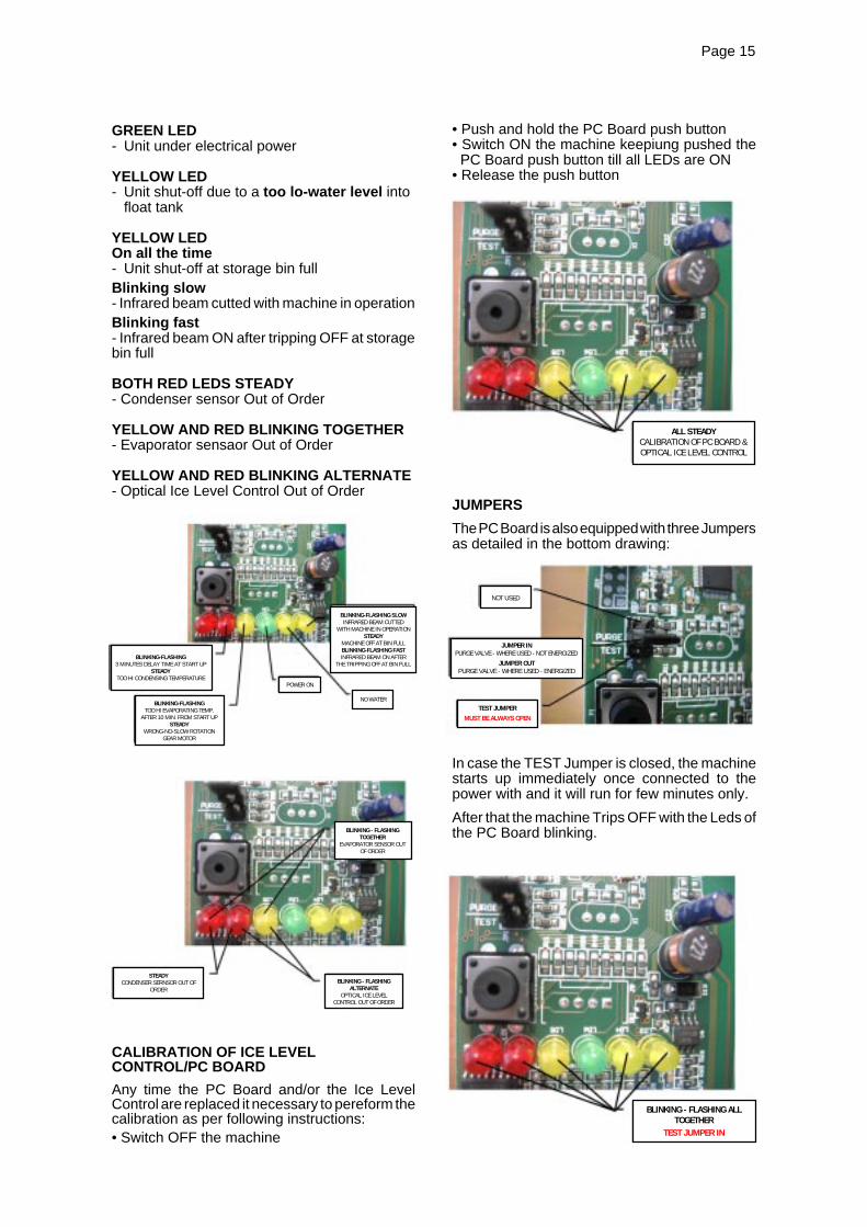
Page 15Page 15
GREEN LED- Unit under electrical power
YELLOW LED- Unit shut-off due to a too lo-water level into
float tank
YELLOW LEDOn all the time- Unit shut-off at storage bin fullBlinking slow- Infrared beam cutted with machine in operationBlinking fast- Infrared beam ON after tripping OFF at storagebin full
BOTH RED LEDS STEADY- Condenser sensor Out of Order
YELLOW AND RED BLINKING TOGETHER- Evaporator sensaor Out of Order
YELLOW AND RED BLINKING ALTERNATE- Optical Ice Level Control Out of Order
CALIBRATION OF ICE LEVELCONTROL/PC BOARD
Any time the PC Board and/or the Ice LevelControl are replaced it necessary to pereform thecalibration as per following instructions:• Switch OFF the machine
• Push and hold the PC Board push button• Switch ON the machine keepiung pushed the
PC Board push button till all LEDs are ON• Release the push button
JUMPERS
The PC Board is also equipped with three Jumpersas detailed in the bottom drawing:
In case the TEST Jumper is closed, the machinestarts up immediately once connected to thepower with and it will run for few minutes only.
After that the machine Trips OFF with the Leds ofthe PC Board blinking.
ALL STEADYCALIBRATION OF PC BOARD &OPTICAL ICE LEVEL CONTROL
BLINKING-FLASHING SLOWINFRARED BEAM CUTTED
WITH MACHINE IN OPERATIONSTEADY
MACHINE OFF AT BIN FULLBLINKING-FLASHING FASTINFRARED BEAM ON AFTER
THE TRIPPING OFF AT BIN FULL
NO WATER
POWER ON
BLINKING-FLASHING3 MINUTES DELAY TIME AT START UP
STEADYTOO HI CONDENSING TEMPERATURE
BLINKING-FLASHINGTOO HI EVAPORATING TEMP.
AFTER 10 MIN. FROM START UPSTEADY
WRONG-NO-SLOW ROTATIONGEAR MOTOR
BLINKING - FLASHINGTOGETHER
EVAPORATOR SENSOR OUTOF ORDER
BLINKING - FLASHINGALTERNATE
OPTICAL ICE LEVELCONTROL OUT OF ORDER
STEADYCONDENSER SERNSOR OUT OF
ORDER
BLINKING - FLASHING ALLTOGETHER
TEST JUMPER IN
NOT USED
JUMPER INPURGE VALVE - WHERE USED - NOT ENERGIZED
JUMPER OUTPURGE VALVE - WHERE USED - ENERGIZED
TEST JUMPERMUST BE ALWAYS OPEN

Page 16Page 16
I. FLOAT RESERVOIR
The float reservoir consists of a plastic water panon which is fitted a float valve with its settingscrew. The float valve modulate the incomingwater flow to maintain a constant water level inthe reservoir, level that corresponds to the one inthe freezing cylinder to ensure proper iceformation and fluidity.On the inner side of the reservoir cover are fittedthe two water level sensors which detects thepresence or the shortage of water in the reservoir.
NOTE. It is very important to make sure ofthe correct fitting of the cover on the reservoirin order to enable the sensor to efficientlycontrol the water situation avoiding undueshutoff interventions.
J. FREEZING CYLINDER (EVAPORATOR)
The freezing cylinder is made of a stainless steelvertical tube on which exterior is wrapped aroundthe cooling coil with the evaporating chamberand in its interior is located the auger whichrotates on its vertical axis and it is maintainedaligned by the top and bottom bearings. A waterseal system is located in the bottom part of thefreezer while at the top end is fitted the icebreaker.The water constantly flowing into the cylinderbottom part, freezes into ice when in contact withthe cylinder inner walls. The ice is then lifted upby the rotating auger and compacted and forcedout by the ice breaker.
K. ICE BREAKER
The ice breaker is made by several rectangularopenings where the ice is forced to pass through.By undergoing this, the ice looses its excess ofwater content so it drops into the bin in hard drybits of ice.In the ice breaker it is housed the top bearingwhich is made of two rolls bearings positioned towithstand the auger axial and radial loads. Thisbearing is lubricated with a food grade - waterresistant grease.
NOTE. It is advisable to check the conditionsof both the lubricant grease and the bearingsevery six months.
L. DRIVE GEAR MOTOR
This motoreducer is made of a single phaseelectric motor with permanent capacitor directlyfitted on a gear box.The drive motor rotor is kept aligned on itsvertical axis by two ball bearings permanentlylubricated. The gear case contains a train ofthree spur gears the first one of which is in fiber
to limit the noise level. All the three gears areencased in case bearings and are covered bylubricant grease (MOBILPLEX IP 44).Two seal rings, one fitted on the rotor shaft andthe other on the output shaft keep the gear casesealed.Hovewer, the interior can be inspected andserviced by unbolting the two halves of thealuminium gear case housing.The gear reducer output shaft is connected to thefreezer auger by a ratched coupling which ismade of two toothed halves that engagesthemselves only if turned in the correct directionnamely, conterclockwise.
M. FAN MOTOR (Air cooled version)
The fan motor is controlled through the P.C.BOARD and the TRIAC by the condenser tempe-rature sensor. Normally it operates to draw coolingair through the condenser fins.In cold ambient situation, the fan motor can run atintermittance as the condenser pressure must bekept between two corresponding head pressurevalues.
N. COMPRESSOR
The hermetic compressor is the heart of therefrigerant system and it is used to circulate andretrieve the refrigerant throughout the entiresystem. It compresses the low pressure refrigerantvapor causing its temperature to rise and becomehigh pressure hot vapor which is then releasedthrough the discharge valve.
O. ICE DISPENSER DRIVE MOTOR
Located on the upper side of the storage bin, itturn by a milled shaft the dispensing vane placedinside the round storage bin.By rotating, the dispensing vane pushes the icetowards the bottom rectangular opening so toforce the nugget ice to go through the bottomoutlet spout.
P. STORAGE BIN
Round shaped it is located in the front of the icemachine and has the main reason to store thenugget ice produced by the evaporator till itreaches its maximum level controlled by aninfrared optical system. In its bottom is placed theice spout as well as the water drain hole.Inside the ice spout opening is also located thewater outlet tube connected to the solenoid val-ve.
Q. DISPENSING WATER SOLENOID VALVE
Energized and controlled by the PC Board, itallows a metered quantity of not chilled water tobe dispensed through the same opening of theice.

Page 17Page 17
WIRING DIAGRAM - DISPENSING BOARD VERSIONAIR AND WATER COOLED
230/50/1

Page 18Page 18
WIRING DIAGRAM - PUSH BUTTONS VERSIONAIR AND WATER COOLED
230/50/1
Page 19Page 19
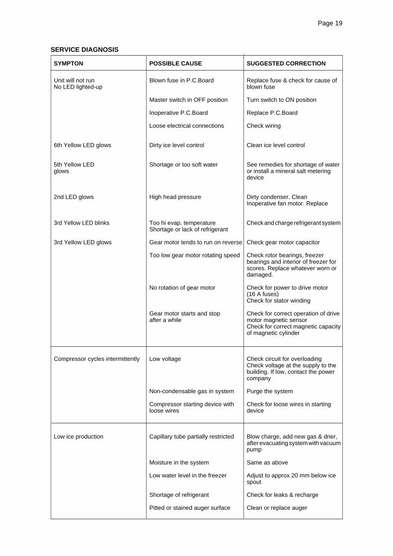
SYMPTON POSSIBLE CAUSE SUGGESTED CORRECTION
Unit will not run Blown fuse in P.C.Board Replace fuse & check for cause ofNo LED lighted-up blown fuse
Master switch in OFF position Turn switch to ON position
Inoperative P.C.Board Replace P.C.Board
Loose electrical connections Check wiring
6th Yellow LED glows Dirty ice level control Clean ice level control
5th Yellow LED Shortage or too soft water See remedies for shortage of waterglows or install a mineral salt metering
device
2nd LED glows High head pressure Dirty condenser. CleanInoperative fan motor. Replace
3rd Yellow LED blinks Too hi evap. temperature Check and charge refrigerant systemShortage or lack of refrigerant
3rd Yellow LED glows Gear motor tends to run on reverse Check gear motor capacitor
Too low gear motor rotating speed Check rotor bearings, freezerbearings and interior of freezer forscores. Replace whatever worn ordamaged.
No rotation of gear motor Check for power to drive motor(16 A fuses)Check for stator winding
Gear motor starts and stop Check for correct operation of driveafter a while motor magnetic sensor
Check for correct magnetic capacityof magnetic cylinder
Compressor cycles intermittently Low voltage Check circuit for overloadingCheck voltage at the supply to thebuilding. If low, contact the powercompany
Non-condensable gas in system Purge the system
Compressor starting device with Check for loose wires in startingloose wires device
Low ice production Capillary tube partially restricted Blow charge, add new gas & drier,after evacuating system with vacuumpump
Moisture in the system Same as above
Low water level in the freezer Adjust to approx 20 mm below icespout
Shortage of refrigerant Check for leaks & recharge
Pitted or stained auger surface Clean or replace auger
SERVICE DIAGNOSIS

Page 20Page 20
SYMPTON POSSIBLE CAUSE SUGGESTED CORRECTION
Wet ice Ambinet temperature too high Move unit to cooler location
High water level in the freezer Lower to approx. 20 mm belowice spout
Faulty compressor Replace
Machine runs but makes no ice Water not entering in the freezer Air look in feed line to freezer.Clogged feed line to freezer. Clean it
Gear stripped Check and repair
Moisture in the system Purge, replace drier and re-charge
Water leaks Water seal leaking Replace water seal
Water feed line to freezer leaking Check and fasten hose clamp
Float valve not closing Check and adjust float valvesetting screw
Excessive noise or chattering Mineral or scale deposit on auger Remove and manually polish augerand inner freezer walls and inner walls of freezer barrel
using emery paper
Low suction pressure Add refrigerant to rise suction pressure
Water feed line to freezer clogged Vent and clean it
Low water level into freezer Adjust to approx. 20 mm belowice spout
Gear motor noise Worn rotor bearings Check and replace
Shortage or poor lubricant in gear Check for proper lubricant openingcase gear case.
Top of gears must be coveredwith lubricant
Gear case bearings and gear Check and replace worn partsracers worn out
Shortage of water Strainer at water inlet fitting clogged Remove strainer and clean
Float reservoir water nozzle Remove float valve and cleanclogged-up nozzle
SERVICE DIAGNOSIS

Page 21Page 21
MAINTENANCE AND CLEANING INSTRUCTION
A. GENERAL
The periods and the procedures for maintenanceand cleaning are given as guides and are not tobe construed as absolute or invariable.Cleaning, especially, will vary depending uponlocal water and ambient conditions and the icevolume produced; and, each icemaker must bemaintened individually, in accordance with itsparticular location requirements.
B. ICEMAKER
The following maintenance should be scheduledat least two times per year on these icemakers.
1. Check and clean the water line strainer.
2. Remove the cover from the float reservoir -care to do not damage the two water sensors -and depress the float to make sure that a fullstream of water enters into the reservoir.
3. Check that the icemaker is levelled in side toside and in front to rear directions.
4. Check that the water level in the waterreservoir is below the overflow but high enoughthat it does not run out of the spout opening.
NOTE. The float must close positively theincoming water flow when the rubber housedin the setting screw, is perpendicular to thewater nozzle.
5. Clean the water system, water reservoirand the interior of freezing cylinder using asolution of SCOTSMAN Ice Machine Cleaner.Refer to procedure C cleaning instructions andafter cleaning will indicate frequency and proce-dure to be followed in local areas.
NOTE. Cleaning requirements varyaccording to the local water conditions andindividual user operation.
6. If required, polish the two sensor rodssecured to the float reservoir cover, heavy scalesediment on them can be removed with the helpof a bit of SCOTSMAN Cleaner plain.
7. With the ice machine and fan motor OFFclean condenser using vacuum cleaner, whiskbroom or non metallic brush taking care to do notdamage the condenser temperature sensor.
8. Check for water leaks and tighten drain lineconnections. Pour water into the sink to be surethat drain line is open and clear.
9. Check the ice level control sensor to testshut-off. Put your hand between the light sourceand the receiver on the upper side of the storagebin so to cut off the light beam for at least 6seconds.This should cause the immediate blinking of the1st YELLOW LED located in the front face of P.C.Board and, 6 seconds later, the total stopping ofthe ice maker with the simultaneous light up ofthe same Yellow LED.Within few seconds from the removal of the handfrom between the sensor lights the ice makerresume its operation.
NOTE. The ice level control uses devicesthat sense light, therefore they must be keptclean enough so they can “see”.Every month clean/wipe the sensing “eyes”with a clean soft cloth.
10. Check for refrigerant leaks and for properfrost line, which should frost as far as approx. 20cm (8") from the compressor.When doubtful about refrigerant charge, installrefrigerant gauges on corresponding Schrädervalves and check for correct refrigerant pressures.(See Operating pressure at page 21 of thismanual).
11. Check that fan blades move freely and arenot touching any surfaces.
12. Remove the ice spout cover, unloose thebolt securing the casting ice sweep and removeit; then inspect the top bearing, wipe clean of allgrease and apply a coating of food grade waterproof grease P/N 263612.00.
NOTE. It is recommended to use only foodgrade and waterproof grease to lubricate thefreezer top bearing.
13. Turn the ice dispensing spout and remove it.Wash and sanitise it.
14. Remove the sink grill for washing andsanitising.
C. CLEANING INSTRUCTIONS OF WATERSYSTEM
1. Switch OFF the Master disconnect switchon the power line.
2. Remove the top panel and later the topcover of storage bin with the dispensing drivemotor.
3. Remove all ice stored in the bin to prevent itfrom getting contaminated with the cleaningsolution.

Page 22Page 22
4. Shut close the water shutoff valve on waterline.
5. Remove the left side panel to gain access tothe water reservoir.
6. Remove the float reservoir cover and with apiece of copper wire jump the two water levelsensors.
7. Remove the right service panel and unloosethe drain plug from the water purge tube so todrain out all water from the freezer. Then re-plugthe purge tube.
CLEANING
8. Prepare the cleaning solution by diluting ina plastic container two liters of warm water (45°-50°C) with a 0,2 liters of SCOTSMAN Ice MachineCleaner.
WARNING. The SCOTSMAN Ice MachineCleaner contains Phosphoric andHydroxyacetic acids. These compoundsare corrosive and may cause burns ifswallowed, DO NOT induce vomiting.Give large amounts of water or milk. CallPhysician immediately. In case of externalcontact flush with water. KEEP OUT OFTHE REACH OF CHILDREN
9. Pour the cleaning solution into the waterreservoir till reaches the proper level.
10. After 15 minutes switch ON the Masterswitch to start the unit.
11. Wait till the machine starts to discharge ice,then continue to slowly pour the cleaning solutioninto the water reservoir taking care to maintainthe level just below the overflow.
NOTE. The ice made with the cleaningsolution is slushy and coloured also, it maytend to loose fluidity creating some resistencein being elevated and extruded; this situationcan be heard by the creacking noise made bythe ice.Should this occure it is recommended to stopfor few minutes the ice machine in order toallow the ice in the freezer to partially melt.
12. When all the cleaning solution has beenused up, open the water shutoff valve to allownew fresh water to flow into the reservoir. Let theunit to continue to run until the ice resumes thenormal colour and hardness.
13. Stop the icemaker and pour warm water onthe ice deposited into the storage bin to melt it up.
NOTE. DO NOT use ice produced with thecleaning solution. Be sure none remains inthe bin.
SANITATION14. Pour into the water reservoir 1 cc. (approx20 drops) of Scotsman Sanitiser (Antialgae P/N264000.02) then switch the unit ON.
15. Left the unit running for approx 10 minutesthen remove the copper wire used to jump thetwo sensors for the water level and place backcorrectly the cover on the float reservoir.
NOTE. DO NOT use ice produced with thesanitising solution.
16. With a sponge moisted with a sanitisingsolution, wipe clean all the bin interior surfaces.
REMEMBER. To prevent the accumulationof undesirable bacteria it is necessary tosanitise the interior of the storage bin with ananti-algae disinfectant solution every week.


![[XLS]pmkvyofficial.orgpmkvyofficial.org/App_Documents/TrainingCentreFile/TC... · Web view1 62420 4 310 180 62420 3 540 90 2 36386 4 310 45 3 15038 4 320 180 15038 4 240 360 4 4476](https://static.fdocuments.us/doc/165x107/5aa315bc7f8b9a80378dd3f7/xls-view1-62420-4-310-180-62420-3-540-90-2-36386-4-310-45-3-15038-4-320-180-15038.jpg)