
Taurus 351-401 Synergic S HP MM FKG;Taurus 351-501 Synergic S ... - EWM … · Taurus 351-401...
123
Operating instructions EN Welding machine Taurus 351-401 Synergic S HP MM FKG Taurus 351-501 Synergic S HP MM FKW 099-005431-EW501 04.02.2016
Transcript of Taurus 351-401 Synergic S HP MM FKG;Taurus 351-501 Synergic S ... - EWM … · Taurus 351-401...

Operating instructions
EN
Welding machine
Taurus 351-401 Synergic S HP MM FKG Taurus 351-501 Synergic S HP MM FKW
099-005431-EW501 04.02.2016

General instructions
CAUTION
Read the operating instructions!
The operating instructions provide an introduction to the safe use of the products.
• Read the operating instructions for all system components!
• Observe accident prevention regulations!
• Observe all local regulations!
• Confirm with a signature where appropriate.
In the event of queries on installation, commissioning, operation or special conditions at the
installation site, or on usage, please contact your sales partner or our customer service
department on +49 2680 181-0.
A list of authorised sales partners can be found at www.ewm-group.com.
Liability relating to the operation of this equipment is restricted solely to the function of the
equipment. No other form of liability, regardless of type, shall be accepted. This exclusion of
liability shall be deemed accepted by the user on commissioning the equipment.
The manufacturer is unable to monitor whether or not these instructions or the conditions and
methods are observed during installation, operation, usage and maintenance of the equipment.
An incorrectly performed installation can result in material damage and injure persons as a
result. For this reason, we do not accept any responsibility or liability for losses, damages or
costs arising from incorrect installation, improper operation or incorrect usage and maintenance
or any actions connected to this in any way.
© EWM AG · Dr. Günter-Henle-Str. 8 · D-56271 Mündersbach, Germany
The copyright to this document remains the property of the manufacturer.
Reprinting, including extracts, only permitted with written approval.
The content of this document has been prepared and reviewed with all reasonable care. The information
provided is subject to change, errors excepted.

Contents Notes on the use of these operating instructions
099-005431-EW501
04.02.2016 3
1 Contents
1 Contents .................................................................................................................................................. 3
2 Safety instructions ................................................................................................................................. 7 2.1 Notes on the use of these operating instructions .......................................................................... 7 2.2 Explanation of icons ....................................................................................................................... 8 2.3 General .......................................................................................................................................... 9 2.4 Transport and installation ............................................................................................................ 13
2.4.1 Lifting by crane ............................................................................................................. 14 2.4.2 Ambient conditions ....................................................................................................... 15
2.4.2.1 In operation ................................................................................................... 15 2.4.2.2 Transport and storage ................................................................................... 15
3 Intended use ......................................................................................................................................... 16 3.1 Applications .................................................................................................................................. 16 3.2 Documents which also apply ....................................................................................................... 17
3.2.1 Warranty ....................................................................................................................... 17 3.2.2 Declaration of Conformity ............................................................................................. 17 3.2.3 Welding in environments with increased electrical hazards ......................................... 17 3.2.4 Service documents (spare parts and circuit diagrams) ................................................ 17 3.2.5 Calibration/Validation ................................................................................................... 17
4 Machine description – quick overview .............................................................................................. 18 4.1 Front view .................................................................................................................................... 18 4.2 Rear view ..................................................................................................................................... 20 4.3 Inside view ................................................................................................................................... 22 4.4 Machine control – Operating elements ........................................................................................ 24
4.4.1 Functional sequence .................................................................................................... 26
5 Design and function ............................................................................................................................. 27 5.1 General ........................................................................................................................................ 27 5.2 Installation .................................................................................................................................... 28 5.3 Machine cooling ........................................................................................................................... 28 5.4 Workpiece lead, general .............................................................................................................. 28 5.5 Welding torch cooling system ...................................................................................................... 29
5.5.1 List of coolants .............................................................................................................. 29 5.5.2 Maximal hose package length ...................................................................................... 29 5.5.3 Adding coolant .............................................................................................................. 30
5.6 Mains connection ......................................................................................................................... 31 5.6.1 Mains configuration ...................................................................................................... 31
5.7 Notes on the installation of welding current leads ....................................................................... 32 5.7.1 Shielding gas supply (shielding gas cylinder for welding machine) ............................. 34
5.7.1.1 Connection .................................................................................................... 35 5.7.2 Gas test ........................................................................................................................ 36
5.7.2.1 Setting the shielding gas quantity ................................................................. 36 5.7.3 Rinse hose package function ....................................................................................... 36 5.7.4 Welding data display .................................................................................................... 37
5.8 MIG/MAG welding ........................................................................................................................ 38 5.8.1 Welding torch and workpiece line connection .............................................................. 38 5.8.2 Wire feed ...................................................................................................................... 41
5.8.2.1 Open the protective flap of the wire feeder ................................................... 41 5.8.2.2 Inserting the wire spool ................................................................................. 41 5.8.2.3 Changing the wire feed rollers ...................................................................... 42 5.8.2.4 Inching the wire electrode ............................................................................. 44 5.8.2.5 Spool brake setting ....................................................................................... 46
5.8.3 Definition of MIG/MAG welding tasks ........................................................................... 47 5.8.4 Welding task selection .................................................................................................. 47
5.8.4.1 Basic welding parameters ............................................................................. 47 5.8.4.2 Operating mode ............................................................................................ 47 5.8.4.3 Choke effect / dynamics ................................................................................ 48 5.8.4.4 superPuls ...................................................................................................... 48

Contents Notes on the use of these operating instructions
4 099-005431-EW501
04.02.2016
5.8.4.5 Burn-back ...................................................................................................... 49 5.8.5 MIG/MAG operating point ............................................................................................. 50
5.8.5.1 Selecting the display unit............................................................................... 50 5.8.5.2 Operating point setting using material thickness .......................................... 50 5.8.5.3 Arc length correction setting .......................................................................... 51 5.8.5.4 Accessory components for operating point setting ....................................... 51 5.8.5.5 forceArc ......................................................................................................... 52 5.8.5.6 rootArc ........................................................................................................... 53
5.8.6 MIG/MAG functional sequences / operating modes ..................................................... 54 5.8.6.1 Explanation of signs and functions ................................................................ 54
5.8.7 MIG/MAG program sequence ("Program steps" mode) ............................................... 64 5.8.7.1 Selection of the program sequence parameter ............................................. 64 5.8.7.2 MIG/MAG overview of parameters ................................................................ 65 5.8.7.3 Example, tack welding (non-latched) ............................................................ 66 5.8.7.4 Example, aluminium tack welding (non-latched special) .............................. 66 5.8.7.5 Example, aluminium welding (latched special) ............................................. 67 5.8.7.6 Example, visible seams (latched super pulse) .............................................. 68
5.8.8 Main program A mode .................................................................................................. 69 5.8.8.1 Selecting parameters (program A) ................................................................ 71
5.8.9 MIG/MAG automatic cut-out ......................................................................................... 71 5.8.10 Standard MIG/MAG torch ............................................................................................. 72 5.8.11 MIG/MAG special-torches............................................................................................. 72
5.8.11.1 Program- and Up- / down operation .............................................................. 72 5.8.11.2 Switching between Push/Pull and intermediate drive ................................... 72
5.8.12 Expert menu (MIG/MAG) .............................................................................................. 73 5.8.12.1 Selection ........................................................................................................ 73
5.9 TIG welding .................................................................................................................................. 75 5.9.1 Welding torch and workpiece line connection .............................................................. 75 5.9.2 Welding task selection .................................................................................................. 76 5.9.3 Welding current setting ................................................................................................. 76 5.9.4 TIG arc ignition ............................................................................................................. 76
5.9.4.1 Liftarc ignition ................................................................................................ 76 5.9.5 Function sequences/operating modes .......................................................................... 77
5.9.5.1 Explanation of signs and functions ................................................................ 77 5.9.6 TIG automatic cut-out ................................................................................................... 80 5.9.7 TIG program sequence ("Program steps" mode) ......................................................... 81
5.10 MMA welding ................................................................................................................................ 82 5.10.1 Connecting the electrode holder and workpiece lead .................................................. 82 5.10.2 Welding task selection .................................................................................................. 83 5.10.3 Welding current setting ................................................................................................. 83 5.10.4 Arcforce......................................................................................................................... 83 5.10.5 Hotstart ......................................................................................................................... 84 5.10.6 Antistick......................................................................................................................... 84 5.10.7 Parameter overview ...................................................................................................... 84
5.11 Remote control ............................................................................................................................. 85 5.12 Interfaces for automation ............................................................................................................. 85
5.12.1 Remote control connection socket, 19-pole ................................................................. 86 5.13 PC Interfaces ............................................................................................................................... 87 5.14 Protecting welding parameters from unauthorised access .......................................................... 87 5.15 Special parameters (advanced settings) ...................................................................................... 88
5.15.1 Selecting, changing and saving parameters................................................................. 89 5.15.1.1 Reset to factory settings ................................................................................ 91 5.15.1.2 Special parameters in detail .......................................................................... 92
5.16 Machine configuration menu ...................................................................................................... 102 5.16.1 Selecting, changing and saving parameters............................................................... 102 5.16.2 Aligning the cable resistance ...................................................................................... 103 5.16.3 Power-saving mode (Standby) ................................................................................... 104
6 Maintenance, care and disposal ....................................................................................................... 105 6.1 General....................................................................................................................................... 105 6.2 Maintenance work, intervals ...................................................................................................... 105
Contents Notes on the use of these operating instructions
099-005431-EW501
04.02.2016 5
6.2.1 Daily maintenance tasks ............................................................................................ 105 6.2.1.1 Visual inspection ......................................................................................... 105 6.2.1.2 Functional test ............................................................................................. 105
6.2.2 Monthly maintenance tasks ........................................................................................ 106 6.2.2.1 Visual inspection ......................................................................................... 106 6.2.2.2 Functional test ............................................................................................. 106
6.2.3 Annual test (inspection and testing during operation) ................................................ 106 6.3 Disposing of equipment ............................................................................................................. 106
6.3.1 Manufacturer's declaration to the end user ................................................................ 106 6.4 Meeting the requirements of RoHS ........................................................................................... 106
7 Rectifying faults ................................................................................................................................. 107 7.1 Checklist for rectifying faults ...................................................................................................... 107 7.2 Error messages .......................................................................................................................... 108 7.3 Resetting JOBs (welding tasks) to the factory settings ............................................................. 110
7.3.1 Resetting a single JOB ............................................................................................... 110 7.3.2 Resetting all JOBs ...................................................................................................... 111
7.4 Vent coolant circuit ..................................................................................................................... 112
8 Technical data .................................................................................................................................... 113 8.1 Taurus 351 FKG ........................................................................................................................ 113 8.2 Taurus 351 FKW ........................................................................................................................ 114 8.3 Taurus 401 FKG ........................................................................................................................ 115 8.4 Taurus 401 FKW ........................................................................................................................ 116 8.5 Taurus 501 FKW ........................................................................................................................ 117
9 Accessories ........................................................................................................................................ 118 9.1 General accessories .................................................................................................................. 118 9.2 Remote control/connecting and extension cable ....................................................................... 118
9.2.1 7-pole connection ....................................................................................................... 118 9.2.2 19-pole connection ..................................................................................................... 118
9.3 Options ....................................................................................................................................... 119 9.4 Computer communication .......................................................................................................... 119
10 Replaceable parts .............................................................................................................................. 120 10.1 Wire feed rollers ......................................................................................................................... 120
10.1.1 Wire feed rollers for steel wire .................................................................................... 120 10.1.2 Wire feed rollers for aluminium wire ........................................................................... 121 10.1.3 Wire feed rollers for cored wire .................................................................................. 121 10.1.4 Wire guide .................................................................................................................. 121
11 Appendix A ......................................................................................................................................... 122 11.1 JOB-List ..................................................................................................................................... 122
12 Appendix B ......................................................................................................................................... 123 12.1 Overview of EWM branches ...................................................................................................... 123

Contents Notes on the use of these operating instructions
6 099-005431-EW501
04.02.2016
Safety instructions Notes on the use of these operating instructions
099-005431-EW501
04.02.2016 7
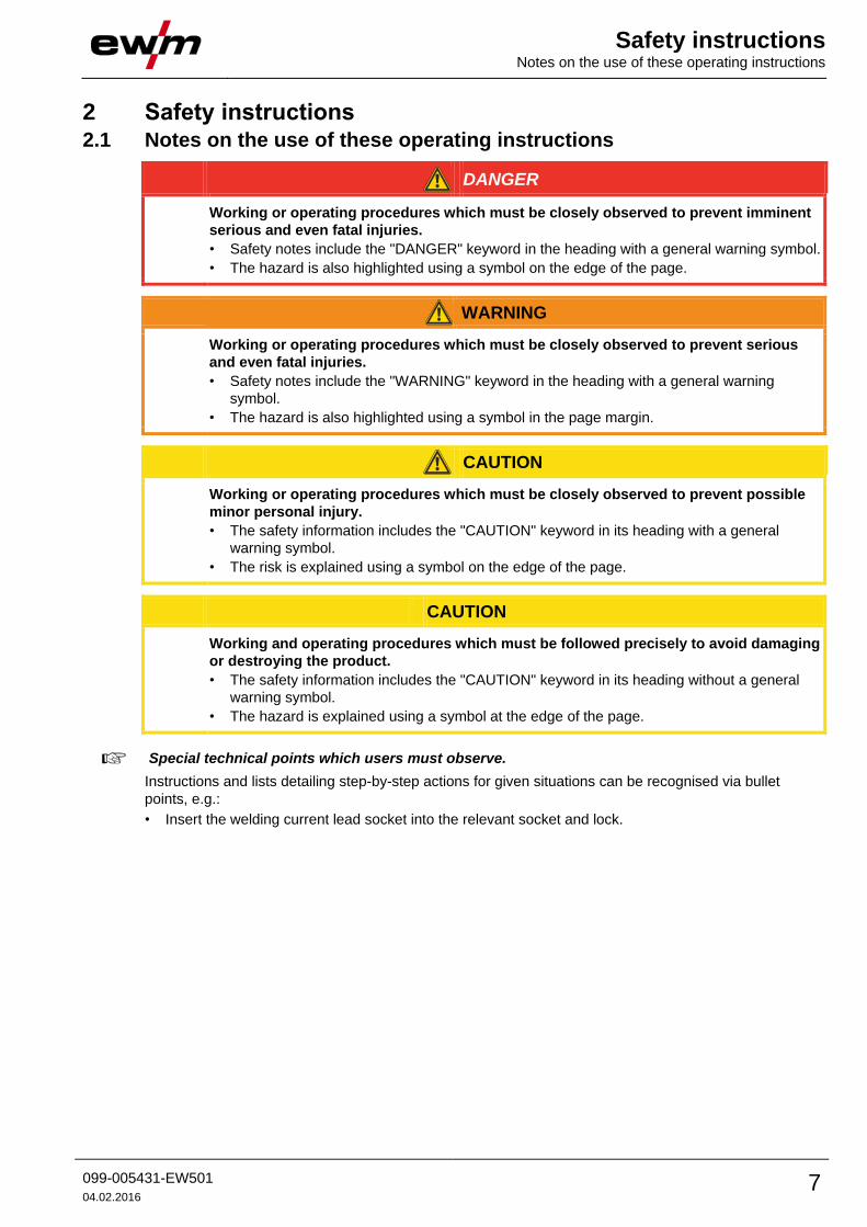
2 Safety instructions 2.1 Notes on the use of these operating instructions
DANGER
Working or operating procedures which must be closely observed to prevent imminent
serious and even fatal injuries.
• Safety notes include the "DANGER" keyword in the heading with a general warning symbol.
• The hazard is also highlighted using a symbol on the edge of the page.
WARNING
Working or operating procedures which must be closely observed to prevent serious
and even fatal injuries.
• Safety notes include the "WARNING" keyword in the heading with a general warning
symbol.
• The hazard is also highlighted using a symbol in the page margin.
CAUTION
Working or operating procedures which must be closely observed to prevent possible
minor personal injury.
• The safety information includes the "CAUTION" keyword in its heading with a general
warning symbol.
• The risk is explained using a symbol on the edge of the page.
CAUTION
Working and operating procedures which must be followed precisely to avoid damaging
or destroying the product.
• The safety information includes the "CAUTION" keyword in its heading without a general
warning symbol.
• The hazard is explained using a symbol at the edge of the page.
Special technical points which users must observe.
Instructions and lists detailing step-by-step actions for given situations can be recognised via bullet
points, e.g.:
• Insert the welding current lead socket into the relevant socket and lock.
Safety instructions Explanation of icons
8 099-005431-EW501
04.02.2016
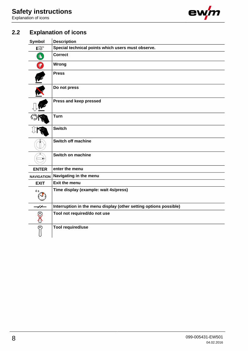
2.2 Explanation of icons
Symbol Description
Special technical points which users must observe.
Correct
Wrong
Press
Do not press
Press and keep pressed
Turn
Switch
Switch off machine
Switch on machine
ENTER enter the menu
NAVIGATION Navigating in the menu
EXIT Exit the menu
4 s
Time display (example: wait 4s/press)
Interruption in the menu display (other setting options possible)
Tool not required/do not use
Tool required/use

Safety instructions General
099-005431-EW501
04.02.2016 9
2.3 General
DANGER
Electric shock!
Welding machines use high voltages which can result in potentially fatal electric shocks
and burns on contact. Even low voltages can cause you to get a shock and lead to
accidents.
• Do not touch any live parts in or on the machine!
• Connection cables and leads must be free of faults!
• Switching off alone is not sufficient!
• Place welding torch and stick electrode holder on an insulated surface!
• The unit should only be opened by specialist staff after the mains plug has been
unplugged!
• Only wear dry protective clothing!
• Wait for 4 minutes until the capacitors have discharged!
Electromagnetic fields!
The power source may cause electrical or electromagnetic fields to be produced which
could affect the correct functioning of electronic equipment such as IT or CNC devices,
telecommunication lines, power cables, signal lines and pacemakers.
• Observe the maintenance instructions - See 6 Maintenance, care and disposal chapter!
• Unwind welding leads completely!
• Shield devices or equipment sensitive to radiation accordingly!
• The correct functioning of pacemakers may be affected (obtain advice from a doctor if
necessary).
Do not carry out any unauthorised repairs or modifications!
To avoid injury and equipment damage, the unit must only be repaired or modified by
specialist, skilled persons!
The warranty becomes null and void in the event of unauthorised interference.
• Appoint only skilled persons for repair work (trained service personnel)!
WARNING
Risk of accidents due to non-compliance with the safety instructions!
Non-compliance with the safety instructions can be fatal!
• Carefully read the safety instructions in this manual!
• Observe the accident prevention regulations and any regional regulations!
• Inform persons in the working area that they must comply with the regulations!
Risk of injury due to radiation or heat!
Arc radiation results in injury to skin and eyes.
Contact with hot workpieces and sparks results in burns.
• Use welding shield or welding helmet with the appropriate safety level (depending on the
application)!
• Wear dry protective clothing (e.g. welding shield, gloves, etc.) according to the relevant
regulations in the country in question!
• Protect persons not involved in the work against arc beams and the risk of glare using
safety curtains!

Safety instructions General
10 099-005431-EW501
04.02.2016
WARNING
Explosion risk!
Apparently harmless substances in closed containers may generate excessive pressure
when heated.
• Move containers with inflammable or explosive liquids away from the working area!
• Never heat explosive liquids, dusts or gases by welding or cutting!
Smoke and gases!
Smoke and gases can lead to breathing difficulties and poisoning. In addition, solvent
vapour (chlorinated hydrocarbon) may be converted into poisonous phosgene due to
the ultraviolet radiation of the arc!
• Ensure that there is sufficient fresh air!
• Keep solvent vapour away from the arc beam field!
• Wear suitable breathing apparatus if appropriate!
Fire hazard!
Flames may arise as a result of the high temperatures, stray sparks, glowing-hot parts
and hot slag produced during the welding process.
Stray welding currents can also result in flames forming!
• Check for fire hazards in the working area!
• Do not carry any easily flammable objects such as matches or lighters.
• Keep appropriate fire extinguishing equipment to hand in the working area!
• Thoroughly remove any residue of flammable substances from the workpiece before
starting welding.
• Only continue work on welded workpieces once they have cooled down.
Do not allow to come into contact with flammable material!
• Connect welding leads correctly!
Danger when coupling multiple power sources!
Coupling multiple power sources in parallel or in series has to be carried out by
qualified personnel and in accordance with the manufacturer's guidelines. Before
bringing the power sources into service for arc welding operations, a test has to verify
that they cannot exceed the maximum allowed open circuit voltage.
• Connection of the machine may be carried out by qualified personnel only!
• When decommissioning individual power sources, all mains and welding current leads have
to be safely disconnected from the welding system as a whole. (Danger due to inverse
voltages!)
• Do not couple welding machines with pole reversing switch (PWS series) or machines for
AC welding, as a minor error in operation can cause the welding voltages to be combined.
CAUTION
Noise exposure!
Noise exceeding 70 dBA can cause permanent hearing damage!
• Wear suitable ear protection!
• Persons located within the working area must wear suitable ear protection!

Safety instructions General
099-005431-EW501
04.02.2016 11
CAUTION
Obligations of the operator!
The respective national directives and laws must be observed for operation of the
machine!
• National implementation of the framework directive (89/391/EWG), as well as the
associated individual directives.
• In particular, directive (89/655/EWG), on the minimum regulations for safety and health
protection when staff members use equipment during work.
• The regulations regarding work safety and accident prevention for the respective country.
• Setting up and operating the machine according to IEC 60974-9.
• Check at regular intervals that users are working in a safety-conscious way.
• Regular checks of the machine according to IEC 60974-4.
Damage due to the use of non-genuine parts!
The manufacturer's warranty becomes void if non-genuine parts are used!
• Only use system components and options (power sources, welding torches, electrode
holders, remote controls, spare parts and replacement parts, etc.) from our range of
products!
• Only insert and lock accessory components into the relevant connection socket when the
machine is switched off.
Damage to the machine due to stray welding currents!
Stray welding currents can destroy protective earth conductors, damage equipment and
electronic devices and cause overheating of components leading to fire.
• Make sure all welding leads are securely connected and check regularly.
• Always ensure a proper and secure electrical connection to the workpiece!
• Set up, attach or suspend all conductive power source components like casing, transport
vehicle and crane frames so they are insulated!
• Do not place any other electronic devices such as drillers or angle grinders, etc., on the
power source, transport vehicle or crane frames unless they are insulated!
• Always put welding torches and electrode holders on an insulated surface when they are
not in use!
Mains connection
Requirements for connection to the public mains network
High-performance machines can influence the mains quality by taking current from the mains
network. For some types of machines, connection restrictions or requirements relating to the
maximum possible line impedance or the necessary minimum supply capacity at the interface
with the public network (Point of Common Coupling, PCC) can therefore apply. In this respect,
attention is also drawn to the machines' technical data. In this case, it is the responsibility of
the operator, where necessary in consultation with the mains network operator, to ensure that
the machine can be connected.
Safety instructions General
12 099-005431-EW501
04.02.2016
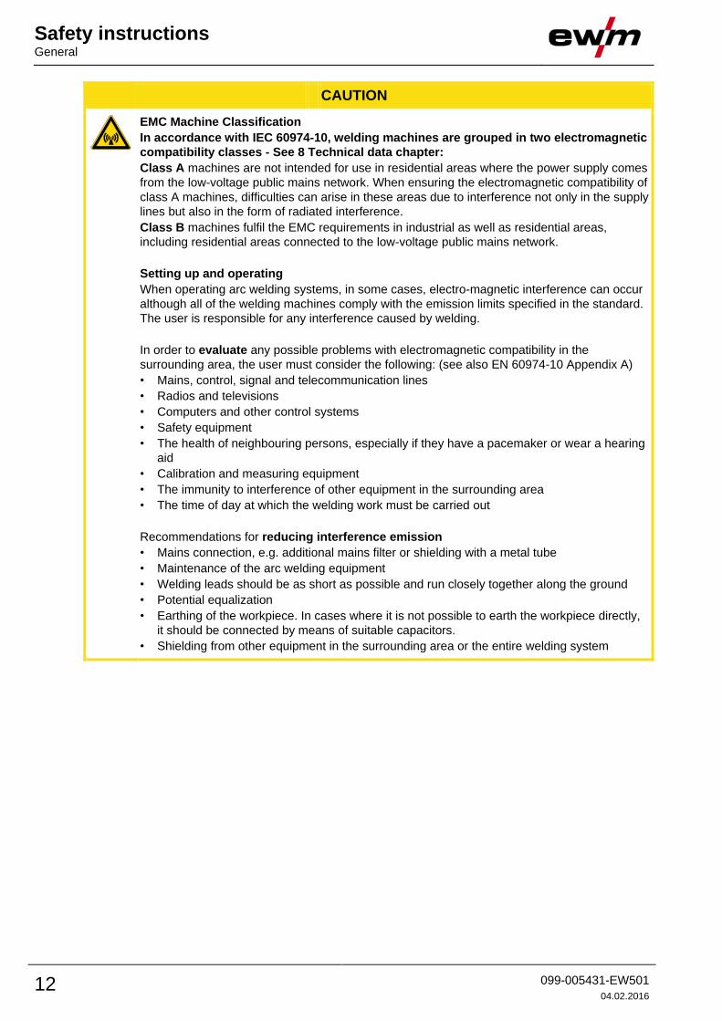
CAUTION
EMC Machine Classification
In accordance with IEC 60974-10, welding machines are grouped in two electromagnetic
compatibility classes - See 8 Technical data chapter:
Class A machines are not intended for use in residential areas where the power supply comes
from the low-voltage public mains network. When ensuring the electromagnetic compatibility of
class A machines, difficulties can arise in these areas due to interference not only in the supply
lines but also in the form of radiated interference.
Class B machines fulfil the EMC requirements in industrial as well as residential areas,
including residential areas connected to the low-voltage public mains network.
Setting up and operating
When operating arc welding systems, in some cases, electro-magnetic interference can occur
although all of the welding machines comply with the emission limits specified in the standard.
The user is responsible for any interference caused by welding.
In order to evaluate any possible problems with electromagnetic compatibility in the
surrounding area, the user must consider the following: (see also EN 60974-10 Appendix A)
• Mains, control, signal and telecommunication lines
• Radios and televisions
• Computers and other control systems
• Safety equipment
• The health of neighbouring persons, especially if they have a pacemaker or wear a hearing
aid
• Calibration and measuring equipment
• The immunity to interference of other equipment in the surrounding area
• The time of day at which the welding work must be carried out
Recommendations for reducing interference emission
• Mains connection, e.g. additional mains filter or shielding with a metal tube
• Maintenance of the arc welding equipment
• Welding leads should be as short as possible and run closely together along the ground
• Potential equalization
• Earthing of the workpiece. In cases where it is not possible to earth the workpiece directly,
it should be connected by means of suitable capacitors.
• Shielding from other equipment in the surrounding area or the entire welding system

Safety instructions Transport and installation
099-005431-EW501
04.02.2016 13
2.4 Transport and installation
WARNING
Incorrect handling of shielding gas cylinders!
Incorrect handling of shielding gas cylinders can result in serious and even fatal injury.
• Observe the instructions from the gas manufacturer and in any relevant regulations
concerning the use of compressed air!
• Place shielding gas cylinders in the holders provided for them and secure with fixing
devices.
• Avoid heating the shielding gas cylinder!
CAUTION
Risk of tipping!
There is a risk of the machine tipping over and injuring persons or being damaged itself
during movement and set up. Tilt resistance is guaranteed up to an angle of 10°
(according to EN 60974-A2).
• Set up and transport the machine on level, solid ground!
• Secure add-on parts using suitable equipment!
• Replace damaged wheels and their fixing elements!
• Fix external wire feed units during transport (avoid uncontrolled rotation)!
Damage due to supply lines not being disconnected!
During transport, supply lines which have not been disconnected (mains supply leads,
control leads, etc.) may cause hazards such as connected equipment tipping over and
injuring persons!
• Disconnect supply lines!
CAUTION
Equipment damage when not operated in an upright position!
The units are designed for operation in an upright position!
Operation in non-permissible positions can cause equipment damage.
• Only transport and operate in an upright position!

Safety instructions Transport and installation
14 099-005431-EW501
04.02.2016
2.4.1 Lifting by crane
WARNING
Risk of injury during lifting by crane!
When lifting the machine by crane, persons may be severely injured by falling machines
or mount-on components.
• Simultaneous lifting of system components such as power source, wire
feeder or cooling unit without suitable crane components is not
allowed. Each system component has to be lifted separately!
• Remove any supply leads and accessories before lifting by crane (e.g.
hose package, wire spool, shielding gas cylinder, toolbox, wire feeder,
remote control,etc.)!)
• Properly close and lock all casing covers and protective caps before
lifting by crane!
• Use the correct number of hoisting equipment of the right size in the
correct position! Observe craning principle (see figure)!
• For machines with lifting eyes: always lift all lifting eyes simultaneously!
• When using retrofitted craning frames etc.: always use at least two
lifting points positioned as far apart as possible – observe option
description.
• Avoid any jerky movements!
• Ensure that the load is distributed evenly! • Use chain hoists and
chain slings of the same length only!
• Stay outside the danger zone underneath the machine!
• Observe the regulations regarding occupational safety and accident
prevention for the respective country.
Craning principle
Risk of injury due to unsuitable lifting eye!
In case of improper use of lifting eyes or the use of unsuitable lifting eyes, persons can
be seriously damaged by falling equipment or add-on components!
• The lifting eye must be completely screwed in!
• The lifting eye must be positioned flat onto and in full contact with the supporting surfaces!
• Check that the lifting eyes are securely fastened before use and check for any damage
(corrosion, deformation)!
• Do not use or screw in damaged lifting eyes!
• Avoid lateral loading of the lifting eyes!
Safety instructions Transport and installation
099-005431-EW501
04.02.2016 15
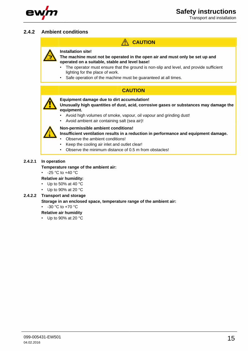
2.4.2 Ambient conditions
CAUTION
Installation site!
The machine must not be operated in the open air and must only be set up and
operated on a suitable, stable and level base!
• The operator must ensure that the ground is non-slip and level, and provide sufficient
lighting for the place of work.
• Safe operation of the machine must be guaranteed at all times.
CAUTION
Equipment damage due to dirt accumulation!
Unusually high quantities of dust, acid, corrosive gases or substances may damage the
equipment.
• Avoid high volumes of smoke, vapour, oil vapour and grinding dust!
• Avoid ambient air containing salt (sea air)!
Non-permissible ambient conditions!
Insufficient ventilation results in a reduction in performance and equipment damage.
• Observe the ambient conditions!
• Keep the cooling air inlet and outlet clear!
• Observe the minimum distance of 0.5 m from obstacles!
2.4.2.1 In operation
Temperature range of the ambient air:
• -25 °C to +40 °C
Relative air humidity:
• Up to 50% at 40 °C
• Up to 90% at 20 °C
2.4.2.2 Transport and storage
Storage in an enclosed space, temperature range of the ambient air:
• -30 °C to +70 °C
Relative air humidity
• Up to 90% at 20 °C

Intended use Applications
16 099-005431-EW501
04.02.2016
3 Intended use
WARNING
Hazards due to improper usage!
Hazards may arise for persons, animals and material objects if the equipment is not
used correctly. No liability is accepted for any damages arising from improper usage!
• The equipment must only be used in line with proper usage and by trained or expert staff!
• Do not modify or convert the equipment improperly!
Arc welding machine for standard and pulsed gas-shielded metal-arc welding with TIG welding and lift arc
(touch starting) or MMA welding as secondary process. It may be possible to expand the functionality by
using accessories (see the documentation in the relevant chapter).
3.1 Applications Machine series Main process Secondary
process
Standard MIG/MAG welding Pulsed MIG/MAG
welding
TIG
we
ldin
g (
lift a
rc)
MM
A w
eld
ing
Go
ug
ing
forc
eA
rc
roo
tArc
co
ldA
rc
pip
eS
olu
tion
forc
eA
rc p
uls
roo
tArc
pu
ls
co
ldA
rc p
uls
alpha Q MM
Phoenix MM
Taurus S MM
possible
not possible

Intended use Documents which also apply
099-005431-EW501
04.02.2016 17
3.2 Documents which also apply 3.2.1 Warranty
For more information refer to the "Warranty registration" brochure supplied and our information
regarding warranty, maintenance and testing at www.ewm-group.com!
3.2.2 Declaration of Conformity
The designated machine conforms to EC Directives and standards in terms of its design
and construction:
• EC Low Voltage Directive (2006/95/EC),
• EC EMC Directive (2004/108/EC),
This declaration shall become null and void in the event of unauthorised modifications, improperly
conducted repairs, non-observance of the deadlines for the repetition test and / or non-permitted
conversion work not specifically authorised by the manufacturer.
The original copy of the declaration of conformity is enclosed with the unit.
3.2.3 Welding in environments with increased electrical hazards
In compliance with IEC / DIN EN 60974, VDE 0544 the machines can be used in
environments with an increased electrical hazard.
3.2.4 Service documents (spare parts and circuit diagrams)
DANGER
Do not carry out any unauthorised repairs or modifications!
To avoid injury and equipment damage, the unit must only be repaired or modified by
specialist, skilled persons!
The warranty becomes null and void in the event of unauthorised interference.
• Appoint only skilled persons for repair work (trained service personnel)!
Original copies of the circuit diagrams are enclosed with the unit.
Spare parts can be obtained from the relevant authorised dealer.
3.2.5 Calibration/Validation We hereby confirm that this machine has been tested using calibrated measuring equipment, as
stipulated in IEC/EN 60974, ISO/EN 17662, EN 50504, and complies with the admissible tolerances.
Recommended calibration interval: 12 months

Machine description – quick overview Front view
18 099-005431-EW501
04.02.2016
4 Machine description – quick overview 4.1 Front view
Coolant tank and quick connect coupling of coolant supply and return are only fitted in machines
with water cooling.
Figure 4-1

Machine description – quick overview Front view
099-005431-EW501
04.02.2016 19
Item Symbol Description 0
1 Lifting lug
2
Ready for operation signal light
Signal light on when the machine is switched on and ready for operation
3
Main switch, machine on/off
4 Carrying handle
5 Cooling air inlet
6
Automatic cut-out of coolant pump key button
press to reset a triggered fuse
7
Quick connect coupling (red)
coolant return
8
Quick connect coupling (blue)
coolant supply
9 Wheels, guide castors
10 Coolant tank
11 Coolant tank cap
12 "-" welding current connection socket
• MIG/MAG welding: Workpiece connection
• MIG/MAG cored wire welding: Welding current to central connection/torch
• TIG welding: Welding current connection for welding torch
• MMA welding: Workpiece or electrode holder connection
13
Connection socket, "+" welding current
• MIG/MAG welding: Welding current to central connection/torch
• MIG/MAG cored wire welding: Workpiece connection
• TIG welding: Workpiece connection
• MMA welding: Workpiece or electrode holder connection
14 Welding current cable, polarity selection
Welding current to Euro torch connector/torch, for polarity selection
• MIG/MAG: Connection socket for “+” welding current
• Self-shielding flux cored wire/TIG: Connection socket, “-” welding current
• MMA: Park socket
15 Welding torch connection (Euro or Dinse torch connector)
Welding current, shielding gas and torch trigger integrated
16
19-pole connection socket (analogue)
For connecting analogue accessory components (remote control, welding torch control
lead, etc.)
17
7-pole connection socket (digital)
For connecting digital accessory components (documentation interface, robot interface
or remote control, etc.).
optional, factory-fitted
18
Key switch for protection against unauthorised use
Position “1” > changes possible,
Position “0” > changes not possible.
- See 5.14 Protecting welding parameters from unauthorised access chapter
optional, factory-fitted
19 Machine control- See 4.4 Machine control – Operating elements chapter
Machine description – quick overview Rear view
20 099-005431-EW501
04.02.2016
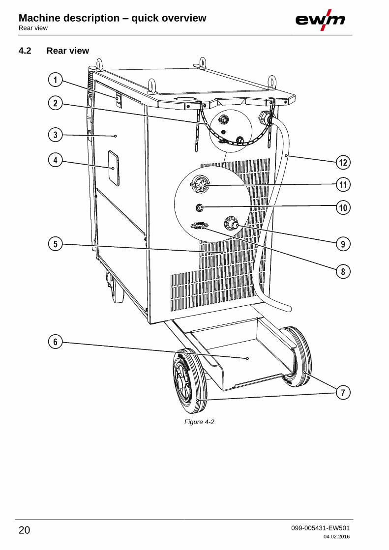
4.2 Rear view
Figure 4-2

Machine description – quick overview Rear view
099-005431-EW501
04.02.2016 21
Item Symbol Description 0
1 Slide latch, lock for the protective cap
2 Securing elements for shielding gas cylinder (strap/chain)
3 Protective cap
Cover for the wire feed mechanism and other operating elements.
Depending on the machine series, additional stickers with information on the
replacement parts and JOB lists will be located on the inside.
4 Wire spool inspection window
Check wire supply
5 Cooling air outlet
6 Bracket for shielding gas cylinder
7 Wheels, fixed castors
8
PC interface, serial (D-Sub connection socket, 9-pole)
9
Connecting nipple G¼, shielding gas connection
10
Key button, automatic cutout
Wire feed motor supply voltage fuse
press to reset a triggered fuse
11
7-pole connection socket (digital)
For connecting digital accessory components (documentation interface, robot interface
or remote control, etc.).
12 Mains connection cable
- See 5.6 Mains connection chapter
Machine description – quick overview Inside view
22 099-005431-EW501
04.02.2016
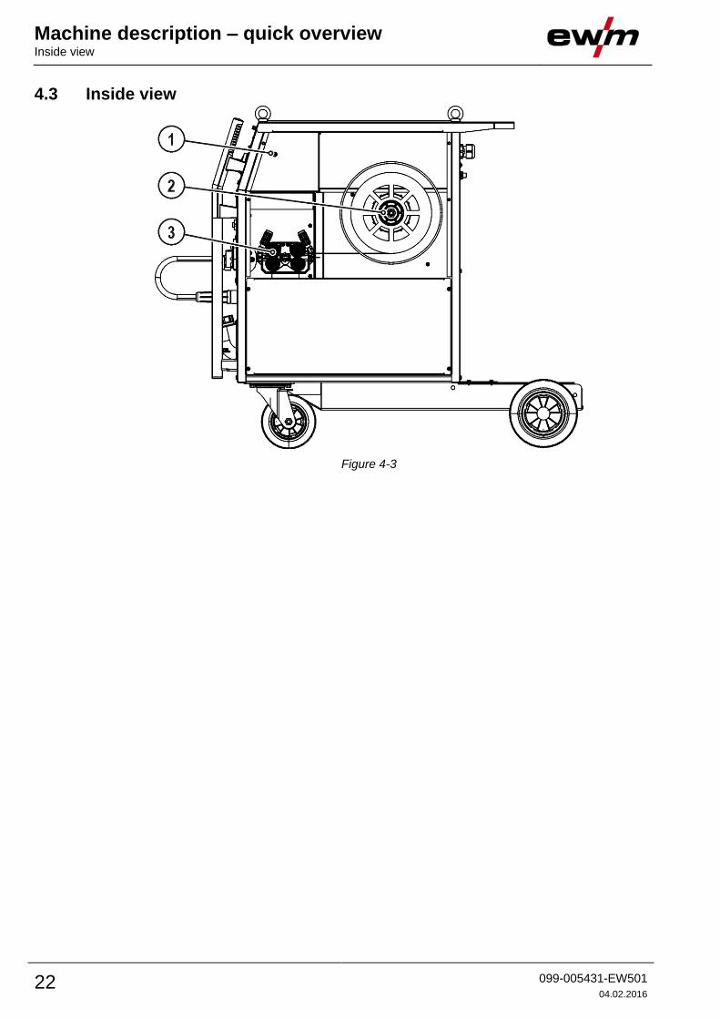
4.3 Inside view
Figure 4-3
Machine description – quick overview Inside view
099-005431-EW501
04.02.2016 23
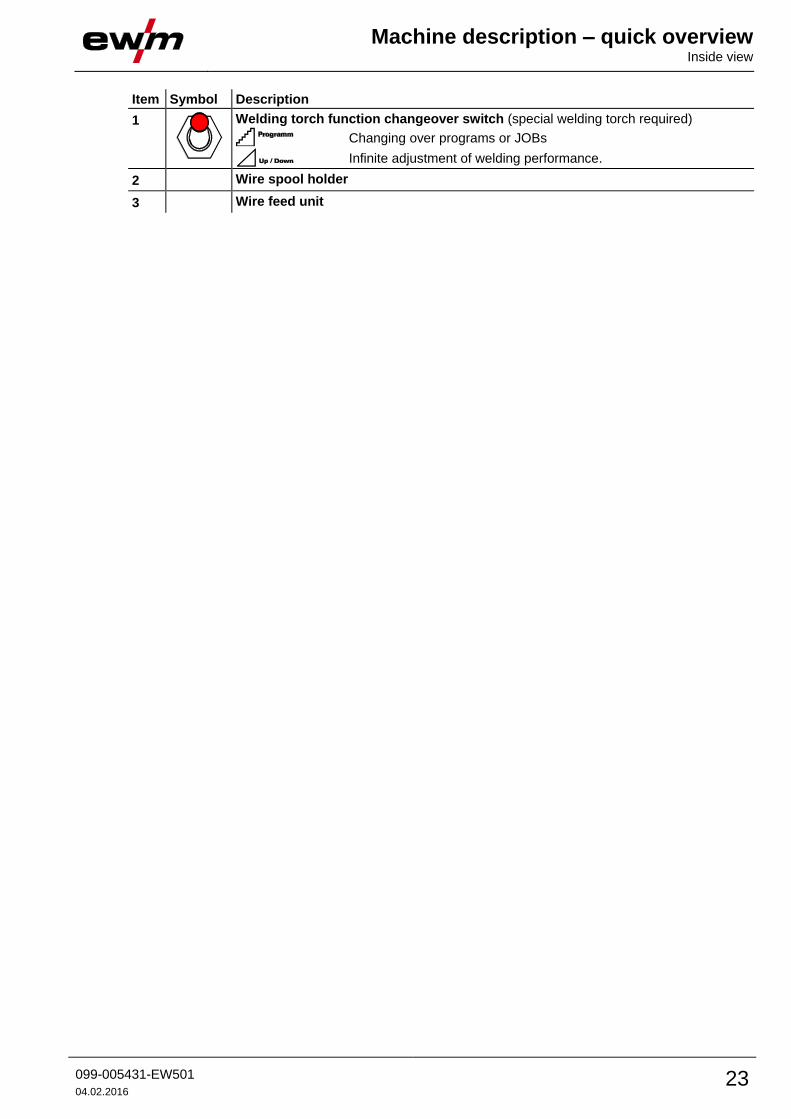
Item Symbol Description 0
1
Welding torch function changeover switch (special welding torch required)
Changing over programs or JOBs
Infinite adjustment of welding performance.
2 Wire spool holder
3 Wire feed unit
Machine description – quick overview Machine control – Operating elements
24 099-005431-EW501
04.02.2016
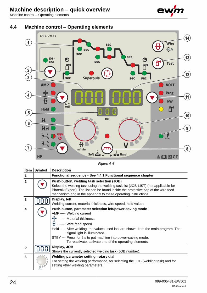
4.4 Machine control – Operating elements
Figure 4-4
Item Symbol Description 0
1 Functional sequence - See 4.4.1 Functional sequence chapter
2
Push-button, welding task selection (JOB)
Select the welding task using the welding task list (JOB-LIST) (not applicable for
Phoenix Expert). The list can be found inside the protective cap of the wire feed
mechanism and in the appendix to these operating instructions.
3
Display, left
Welding current, material thickness, wire speed, hold values
4
Push-button, parameter selection left/power-saving mode
AMP ----- Welding current
------- Material thickness
------- Wire feed speed
Hold ----- After welding, the values used last are shown from the main program. The
signal light is illuminated.
STBY --- Press for 2 s to put machine into power-saving mode.
To reactivate, activate one of the operating elements.
5
Display, JOB
Shows the currently selected welding task (JOB number).
6
Welding parameter setting, rotary dial
For setting the welding performance, for selecting the JOB (welding task) and for
setting other welding parameters.

Machine description – quick overview Machine control – Operating elements
099-005431-EW501
04.02.2016 25
Item Symbol Description 0
7
Select operating mode button
Non-latched
Latched
Signal light lights up in green: Special non-latched
Signal light lights up in red: MIG spot welding
Special latched
8
Push-button, throttling effect (arc dynamics)
Arc is harder and more narrow
Arc is softer and wider
9
Standard MIG/MAG welding signal light
10
Arc length correction/selection of welding program, rotary dial
• Correction of the arc length from -9.9 V to +9.9 V.
• Selection of welding programs 0 to 15 (not possible if accessory components, such
as program torches, are connected).
11
Button, Parameter selection (right)
VOLT Welding voltage
Prog Program number
kW ------- Welding performance display
------- Gas flow quantity (optional)
12
Display, right
Welding voltage, program number, motor current (wire feed mechanism)
13
Gas test / rinse button
• Gas test: For setting the shielding gas quantity
• Rinse: For rinsing longer hose packages
- See 5.7.1 Shielding gas supply (shielding gas cylinder for welding machine) chapter
14
Push-button, wire inching/motor current (wire feed mechanism)
- See 5.8.2.4 Inching the wire electrode chapter

Machine description – quick overview Machine control – Operating elements
26 099-005431-EW501
04.02.2016
4.4.1 Functional sequence
Figure 4-5
Item Symbol Description 0
1
Select welding parameters button
This button is used to select the welding parameters depending on the welding process
and operating mode used.
2
Signal light, gas pre-flow time
Setting range 0.0 s to 20.0 s
3 Signal light, start program (PSTART)
• Wire speed:1% to 200% of the main program PA
• Correction of the arc length -9.9 V to +9.9 V
4 sec Signal light, start time
Setting range, absolute 0.0 s to 20.0 s (0.1 s increments)
5 sec Signal light, slope time program PSTART to main program PA
Setting range 0.0 s to 20.0 s (0.1 s increments)
6 Signal light, main program (PA)
• Wire speed WF-min. to WF-max.
• Correction of the arc length -9.9 V to +9.9 V
7 sec Signal light, duration of main program PA
Setting range 0.1 s to 20.0 s (0.1 s increments).
Used e.g. in connection with the super pulse function
8 Signal light, reduced main program (PB)
• Wire speed:1% to 200% of the main program PA
• Correction of the arc length -9.9 V to +9.9 V
9 sec Signal light, duration reduced main program PB
Setting range 0.0 s to 20.0 s (0.1 s increments).
Used e.g. in connection with the super pulse function.
10 sec Signal light, slope time program PA (or PB) to end program PEND
Setting range 0.0 s to 20.0 s (0.1 s increments)
11 Signal light, end program (PEND)
• Wire speed:1% to 200% of the main program PA
• Correction of the arc length -9.9 V to +9.9 V
12 sec Signal light, duration of end program PEND
Setting range 0.0 s to 20.0 s (0.1 s increments)
13
Signal light, gas post-flow time
Setting range 0.0 s to 20.0 s
14 Super-
puls
Signal lamp, super pulse function
Lights up when the super pulse function is active.
Design and function General
099-005431-EW501
04.02.2016 27
5 Design and function 5.1 General
WARNING
Risk of injury from electric shock!
Contact with live parts, e.g. welding current sockets, is potentially fatal!
• Follow safety instructions on the opening pages of the operating instructions.
• Commissioning may only be carried out by persons who have the relevant expertise of
working with arc welding machines!
• Connection and welding leads (e.g. electrode holder, welding torch, workpiece lead,
interfaces) may only be connected when the machine is switched off!
CAUTION
Insulate the arc welder from welding voltage!
Not all active parts of the welding current circuit can be shielded from direct contact. To
avoid any associated risks it is vital for the welder to adhere to the relevant safety
regulations. Even low voltages can cause a shock and lead to accidents.
• Wear dry and undamaged protective clothing (shoes with rubber soles/welder's gloves
made from leather without any studs or braces)!
• Avoid direct contact with non-insulated connection sockets or connectors!
• Always place torches and electrode holders on an insulated surface!
Risk of burns on the welding current connection!
If the welding current connections are not locked, connections and leads heat up and
can cause burns, if touched!
• Check the welding current connections every day and lock by turning in clockwise direction,
if necessary.
Risk from electrical current!
If welding is carried out alternately using different methods and if a welding torch and
an electrode holder remain connected to the machine, the open-circuit/welding voltage
is applied simultaneously on all cables.
• The torch and the electrode holder should therefore always be placed on an insulated
surface before starting work and during breaks.
CAUTION
Damage due to incorrect connection!
Accessory components and the power source itself can be damaged by incorrect
connection!
• Only insert and lock accessory components into the relevant connection socket when the
machine is switched off.
• Comprehensive descriptions can be found in the operating instructions for the relevant
accessory components.
• Accessory components are detected automatically after the power source is switched on.
Using protective dust caps!
Protective dust caps protect the connection sockets and therefore the machine against
dirt and damage.
• The protective dust cap must be fitted if there is no accessory component being operated
on that connection.
• The cap must be replaced if faulty or if lost!
Design and function Installation
28 099-005431-EW501
04.02.2016
5.2 Installation
CAUTION
Installation site!
The machine must not be operated in the open air and must only be set up and
operated on a suitable, stable and level base!
• The operator must ensure that the ground is non-slip and level, and provide sufficient
lighting for the place of work.
• Safe operation of the machine must be guaranteed at all times.
5.3 Machine cooling To obtain an optimal duty cycle from the power components, the following precautions should be
observed:
• Ensure that the working area is adequately ventilated.
• Do not obstruct the air inlets and outlets of the machine.
• Do not allow metal parts, dust or other objects to get into the machine.
5.4 Workpiece lead, general
CAUTION
Risk of burns due to incorrect connection of the workpiece lead!
Paint, rust and dirt on the connection restrict the power flow and may lead to stray
welding currents.
Stray welding currents may cause fires and injuries!
• Clean the connections!
• Fix the workpiece lead securely!
• Do not use structural parts of the workpiece as a return lead for the welding current!
• Take care to ensure faultless power connections!
Design and function Welding torch cooling system
099-005431-EW501
04.02.2016 29
5.5 Welding torch cooling system
CAUTION
Coolant mixtures!
Mixtures with other liquids or the use of unsuitable coolants result in material damage
and renders the manufacturer's warranty void!
• Only use the coolant described in this manual (overview of coolants).
• Do not mix different coolants.
• When changing the coolant, the entire volume of liquid must be changed.
Insufficient frost protection in the welding torch coolant!
Depending on the ambient conditions, different liquids are used for cooling the welding
torch - See 5.5.1 List of coolants chapter.
Coolants with frost protection (KF 37E or KF 23E) must be checked regularly to ensure
that the frost protection is adequate to prevent damage to the machine or the accessory
components.
• The coolant must be checked for adequate frost protection with the TYP 1 frost protection
tester .
• Replace coolant as necessary if frost protection is inadequate!
The disposal of coolant must be carried out according to official regulations and observing the
relevant safety data sheets (German waste code number: 70104)!
Coolant must not be disposed of together with household waste.
Coolant must not be discharged into the sewerage system.
Recommended cleaning agent: water, if necessary with cleaning agent added.
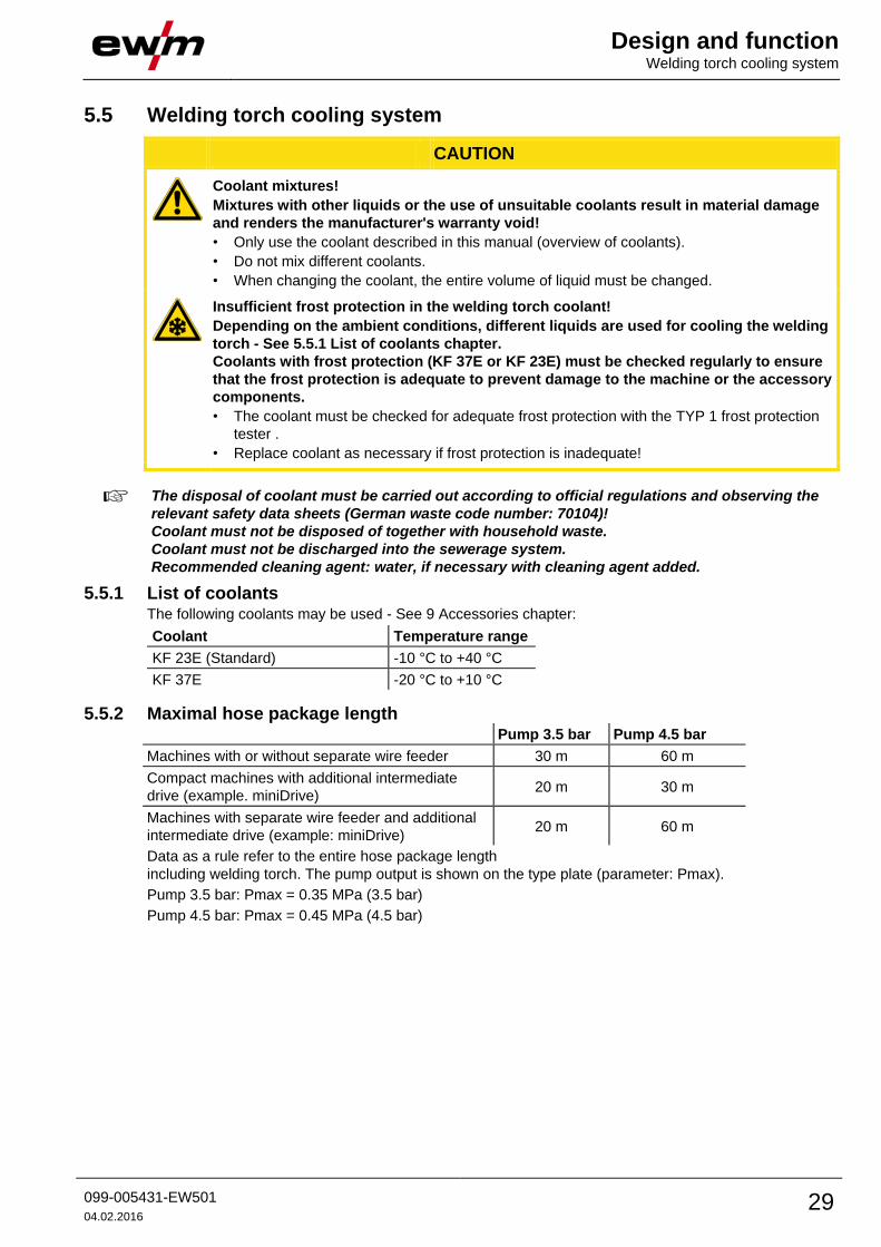
5.5.1 List of coolants The following coolants may be used - See 9 Accessories chapter:
Coolant Temperature range
KF 23E (Standard) -10 °C to +40 °C
KF 37E -20 °C to +10 °C
5.5.2 Maximal hose package length Pump 3.5 bar Pump 4.5 bar
Machines with or without separate wire feeder 30 m 60 m
Compact machines with additional intermediate
drive (example. miniDrive) 20 m 30 m
Machines with separate wire feeder and additional
intermediate drive (example: miniDrive) 20 m 60 m
Data as a rule refer to the entire hose package length
including welding torch. The pump output is shown on the type plate (parameter: Pmax).
Pump 3.5 bar: Pmax = 0.35 MPa (3.5 bar)
Pump 4.5 bar: Pmax = 0.45 MPa (4.5 bar)
Design and function Welding torch cooling system
30 099-005431-EW501
04.02.2016
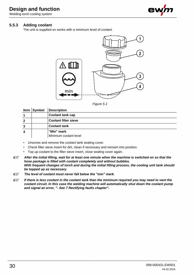
5.5.3 Adding coolant The unit is supplied ex works with a minimum level of coolant.
Figure 5-1
Item Symbol Description 0
1 Coolant tank cap
2 Coolant filter sieve
3 Coolant tank
4 "Min" mark
Minimum coolant level
• Unscrew and remove the coolant tank sealing cover.
• Check filter sieve insert for dirt, clean if necessary and reinsert into position.
• Top up coolant to the filter sieve insert, close sealing cover again.
After the initial filling, wait for at least one minute when the machine is switched on so that the
hose package is filled with coolant completely and without bubbles.
With frequent changes of torch and during the initial filling process, the cooling unit tank should
be topped up as necessary.
The level of coolant must never fall below the “min” mark.
If there is less coolant in the coolant tank than the minimum required you may need to vent the
coolant circuit. In this case the welding machine will automatically shut down the coolant pump
and signal an error, "- See 7 Rectifying faults chapter".
Design and function Mains connection
099-005431-EW501
04.02.2016 31
5.6 Mains connection
DANGER
Hazard caused by improper mains connection!
An improper mains connection can cause injuries or damage property!
• Only use machine with a plug socket that has a correctly fitted protective conductor.
• If a mains plug must be fitted, this may only be carried out by an electrician in accordance
with the relevant national provisions or regulations!
• Mains plug, socket and lead must be checked regularly by an electrician!
• When operating the generator always ensure it is earthed as stated in the operating
instructions. The resulting network has to be suitable for operating devices according to
protection class 1.
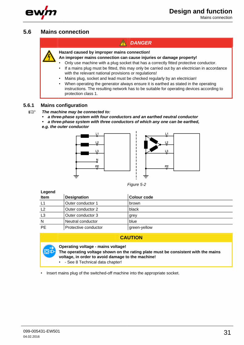
5.6.1 Mains configuration
The machine may be connected to:
• a three-phase system with four conductors and an earthed neutral conductor
• a three-phase system with three conductors of which any one can be earthed,
e.g. the outer conductor
Figure 5-2
Legend
Item Designation Colour code
L1 Outer conductor 1 brown
L2 Outer conductor 2 black
L3 Outer conductor 3 grey
N Neutral conductor blue
PE Protective conductor green-yellow
CAUTION
Operating voltage - mains voltage!
The operating voltage shown on the rating plate must be consistent with the mains
voltage, in order to avoid damage to the machine!
• - See 8 Technical data chapter!
• Insert mains plug of the switched-off machine into the appropriate socket.

Design and function Notes on the installation of welding current leads
32 099-005431-EW501
04.02.2016
5.7 Notes on the installation of welding current leads
Incorrectly installed welding current leads can cause faults in the arc (flickering).
Lay the workpiece lead and hose package of power sources without HF igniter (MIG/MAG) for as
long and as close as possible in parallel.
Lay the workpiece lead and hose package of power sources with HF igniter (TIG) for as long as
possible in parallel with a distance of 20 cm to avoid HF sparkover.
Always keep a distance of at least 20 cm to leads of other power sources to avoid interferences
Always keep leads as short as possible! For optimum welding results max. 30 m (welding lead +
intermediate hose package + torch lead).
Figure 5-3
Design and function Notes on the installation of welding current leads
099-005431-EW501
04.02.2016 33
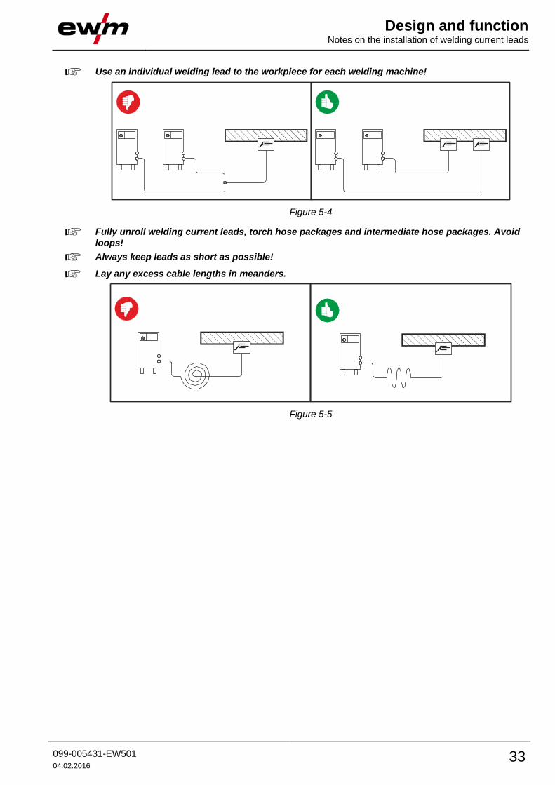
Use an individual welding lead to the workpiece for each welding machine!
Figure 5-4
Fully unroll welding current leads, torch hose packages and intermediate hose packages. Avoid
loops!
Always keep leads as short as possible!
Lay any excess cable lengths in meanders.
Figure 5-5

Design and function Notes on the installation of welding current leads
34 099-005431-EW501
04.02.2016
5.7.1 Shielding gas supply (shielding gas cylinder for welding machine)
WARNING
Risk of injury due to improper handling of shielding gas cylinders!
Improper handling and insufficient securing of shielding gas cylinders
can cause serious injuries!
• Secure shielding gas cylinders using the standard fastening elements on
the unit (chain/belt)!
• The fastening elements must tightly enclose the shielding gas cylinder!
• Attach the fastening elements within the upper half of the shielding gas
cylinder!
• Do not attach any element to the shielding gas cylinder valve!
• Observe the instructions from the gas manufacturer and any relevant
regulations concerning the use of compressed air!
• Avoid heating the shielding gas cylinder!
CAUTION
Faults in the shielding gas supply.
An unhindered shielding gas supply from the shielding gas cylinder to the welding
torch is a fundamental requirement for optimum welding results. In addition, a blocked
shielding gas supply may result in the welding torch being destroyed.
• Always re-fit the yellow protective cap when not using the shielding gas connection.
• All shielding gas connections must be gas tight.
Before connecting the pressure regulator to the gas cylinder, open the cylinder valve briefly to
expel any dirt.
Design and function Notes on the installation of welding current leads
099-005431-EW501
04.02.2016 35
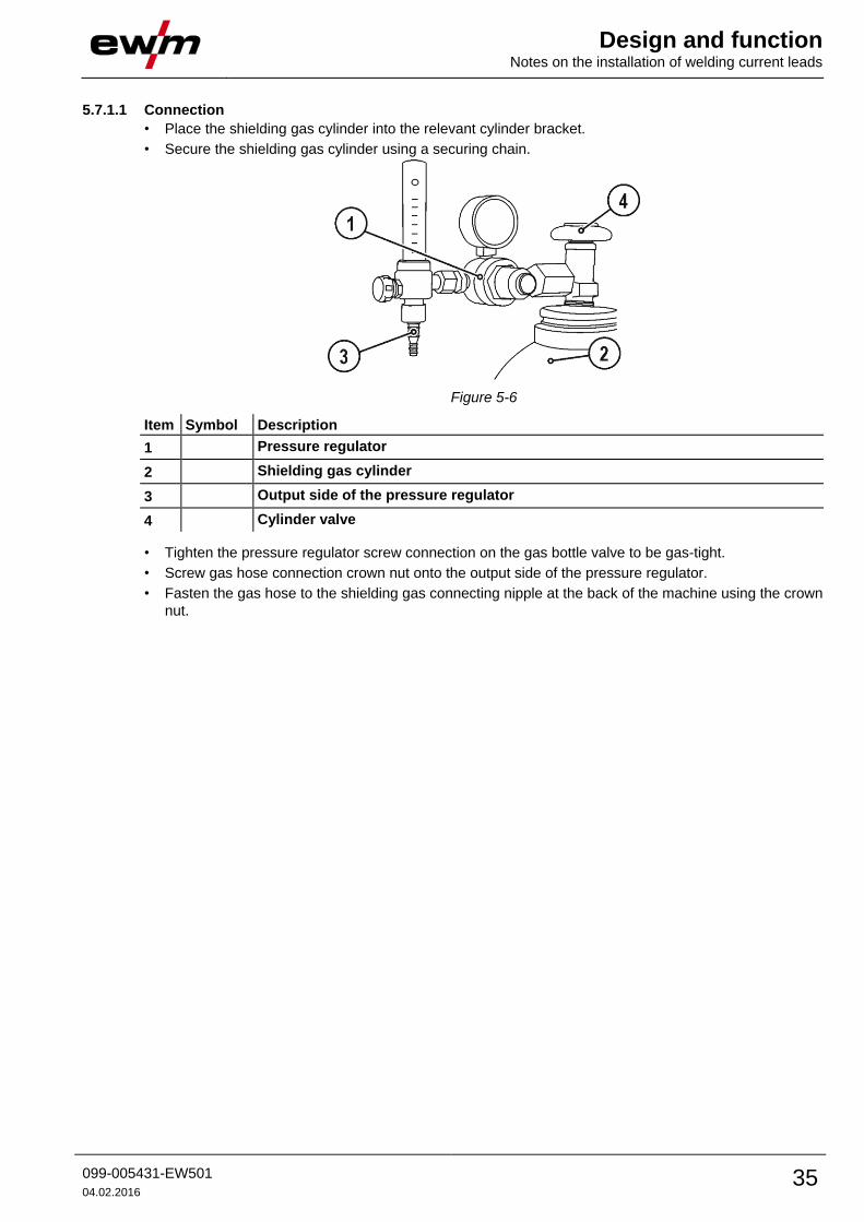
5.7.1.1 Connection
• Place the shielding gas cylinder into the relevant cylinder bracket.
• Secure the shielding gas cylinder using a securing chain.
Figure 5-6
Item Symbol Description 0
1 Pressure regulator
2 Shielding gas cylinder
3 Output side of the pressure regulator
4 Cylinder valve
• Tighten the pressure regulator screw connection on the gas bottle valve to be gas-tight.
• Screw gas hose connection crown nut onto the output side of the pressure regulator.
• Fasten the gas hose to the shielding gas connecting nipple at the back of the machine using the crown
nut.

Design and function Notes on the installation of welding current leads
36 099-005431-EW501
04.02.2016
5.7.2 Gas test • Slowly open the gas cylinder valve.
• Open the pressure regulator.
• Switch on the power source at the main switch.
• Initiate gas test function on the machine control.
• Set the relevant gas quantity for the application on the pressure regulator.
• The gas test is triggered on the machine control by pressing the button briefly.
Shielding gas flows for around 25 seconds or until the button is pressed again.
5.7.2.1 Setting the shielding gas quantity
Welding process Recommended shielding gas quantity
MAG welding Wire diameter x 11.5 = l/min
MIG brazing Wire diameter x 11.5 = l/min
MIG welding (aluminium) Wire diameter x 13.5 = l/min (100 % argon)
TIG Gas nozzle diameter in mm corresponds to l/min gas throughput
Helium-rich gas mixtures require a higher gas volume!
The table below can be used to correct the gas volume calculated where necessary:
Shielding gas Factor
75% Ar/25% He 1.14
50% Ar/50% He 1.35
25% Ar/75% He 1.75
100% He 3.16
Incorrect shielding gas setting!
• If the shielding gas setting is too low or too high, this can introduce air to the weld pool and
may cause pores to form.
• Adjust the shielding gas quantity to suit the welding task!
5.7.3 Rinse hose package function
Operating
Element
Action Result
5 s
Select rinse hose package.
Shielding gas flows continuously until the Gas Test button is pressed
again.
Design and function Notes on the installation of welding current leads
099-005431-EW501
04.02.2016 37
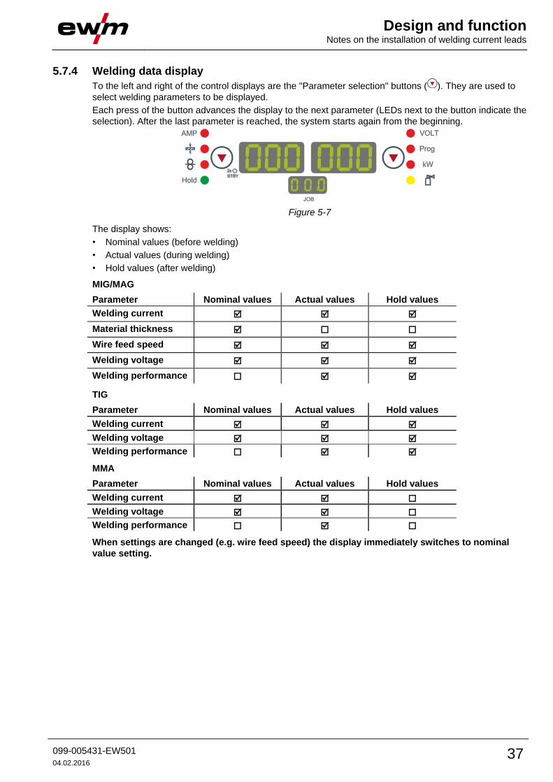
5.7.4 Welding data display
To the left and right of the control displays are the "Parameter selection" buttons ( ). They are used to
select welding parameters to be displayed.
Each press of the button advances the display to the next parameter (LEDs next to the button indicate the
selection). After the last parameter is reached, the system starts again from the beginning.
Figure 5-7
The display shows:
• Nominal values (before welding)
• Actual values (during welding)
• Hold values (after welding)
MIG/MAG
Parameter Nominal values Actual values Hold values
Welding current
Material thickness
Wire feed speed
Welding voltage
Welding performance
TIG
Parameter Nominal values Actual values Hold values
Welding current
Welding voltage
Welding performance
MMA
Parameter Nominal values Actual values Hold values
Welding current
Welding voltage
Welding performance
When settings are changed (e.g. wire feed speed) the display immediately switches to nominal
value setting.

Design and function MIG/MAG welding
38 099-005431-EW501
04.02.2016
5.8 MIG/MAG welding 5.8.1 Welding torch and workpiece line connection
CAUTION
Equipment damage due to improperly connected coolant pipes!
If the coolant pipes are not properly connected or a gas-cooled welding torch is used,
the coolant circuit is interrupted and equipment damage can occur.
• Connect all coolant pipes correctly!
• Completely unroll the hose package and the torch hose package!
• Observe maximal hose package length - See 9 Accessories chapter.
• When using a gas-cooled welding torch, use a hose bridge to establish the coolant circuit -
See 9 Accessories chapter.
On delivery, the Euro torch connector is fitted with a capillary tube for welding torches with a
steel liner. Conversion is necessary if a welding torch with a liner is used!
• Operate welding torches with a liner > with a guide tube.
• Operate welding torches with a steel liner > with a capillary tube.
Depending on the wire electrode diameter or type, either a steel liner or liner with the correct inner
diameter must be inserted in the torch!
Recommendation:
• Use a steel liner when welding hard, unalloyed wire electrodes (steel).
• Use a chrome nickel liner when welding hard, high-alloy wire electrodes (CrNi).
• Use a liner to weld or braze soft wire electrodes, high-alloy wire electrodes or aluminium materials.
Preparation for connecting welding torches with a liner:
• Push forward the capillary tube on the wire feed side in the direction of the Euro torch connector and
remove it there.
• Insert the liner guide tube from the Euro torch connector side.
• Carefully insert the welding torch connector with as yet too long a liner into the Euro torch connector
and secure with a crown nut.
• Cut off the liner with a liner cutter just before the wire feed roller.
• Loosen the welding torch connector and remove.
• Carefully chamfer the cut off end of the liner with a liner sharpener and sharpen.

Design and function MIG/MAG welding
099-005431-EW501
04.02.2016 39
Some wire electrodes (e.g. self-shielding cored wire) are welded using negative polarity. In this
case, the welding current lead should be connected to the "-" welding current socket, and the
workpiece lead should be connected to the "+" welding current socket. Observe the information
from the electrode manufacturer!
Figure 5-8
Item Symbol Description 0
1
Workpiece
2 "-" welding current connection socket
• ----------- MIG/MAG welding: Workpiece connection
3
Welding torch
4 Welding torch hose package
5
19-pole connection socket (analogue)
For connecting analogue accessory components (remote control, welding torch control
lead, etc.)
6 Welding torch connection (Euro or Dinse torch connector)
Welding current, shielding gas and torch trigger integrated
7 Welding current cable, polarity selection
Welding current to central connection/torch. Permits polarity selection for MIG/MAG
welding.
• ----------- Standard applications > Connection for "+" welding current connection socket
8
Quick connect coupling (red)
coolant return
9
Quick connect coupling (blue)
coolant supply

Design and function MIG/MAG welding
40 099-005431-EW501
04.02.2016
• Insert the central plug for the welding torch into the central connector and screw together with crown
nut.
• Insert the plug on the workpiece lead into the "-" welding current connection socket and lock.
• Welding current lead, insert polarity selection into the "+" welding current connection socket and lock.
• Insert the welding torch control cable into the 19-pole connection socket and lock (MIG/MAG torches
with additional control cables only).
Where applicable:
• Lock connecting nipples of the cooling water tubes into the corresponding quick connect couplings:
Return line red to quick connect coupling, red (coolant return) and
supply line blue to quick connect coupling, blue (coolant supply).

Design and function MIG/MAG welding
099-005431-EW501
04.02.2016 41
5.8.2 Wire feed
5.8.2.1 Open the protective flap of the wire feeder
CAUTION
To perform the following steps, the protective flap of the wire feeder needs to be
opened. Make sure to close the protective flap again before starting to work.
• Unlock and open protective flap.
5.8.2.2 Inserting the wire spool
CAUTION
Risk of injury due to incorrectly secured wire spool.
If the wire spool is not secured properly, it may come loose from the wire spool holder
and fall to the ground, causing damage to the machine and injuries.
• Securely fasten the wire spool to the wire spool holder using the knurled nut.
• Before you start working, always check the wire spool is securely fastened.
Standard D300 wire spool holder can be used. Adapters - See 9 Accessories chapter are required
when using standardised basket coils (DIN 8559).
Figure 5-9
Item Symbol Description 0
1 Carrier pin
For fixing the wire spool
2 Knurled nut
For fixing the wire spool
• Loosen knurled nut from spool holder.
• Fix welding wire reel onto the spool holder so that the carrier pin locks into the spool bore.
• Fasten wire spool using knurled nut.

Design and function MIG/MAG welding
42 099-005431-EW501
04.02.2016
5.8.2.3 Changing the wire feed rollers
Figure 5-10
Item Symbol Description 0
1 Tommy
The tommy is used to secure the closure brackets of the wire feed rollers.
2 Closure bracket
The closure brackets are used to secure the wire feed rollers.
3 Feed roll tensioner
Fixing the clamping unit and setting the pressure.
4 Clamping unit
5 Wire feed roller
see the Wire feed roller overview table
• Rotate the tommy by 90° clockwise or anti-clockwise (tommy locks into place).
• Fold the closure brackets outwards by 90°.
• Unfasten pressure units and fold out (clamping units and pressure rollers will automatically flip
upwards).
• Remove the wire feed rollers from the roller support.
• Select new wire feed rollers accoridng to the Wire feed roller overview table and reassemble the wire
feed mechanism in reverse order.

Design and function MIG/MAG welding
099-005431-EW501
04.02.2016 43
Unsatisfactory welding results due to faulty wire feeding!
The wire feed rollers must be suitable for the diameter of the wire and the material. The wire feed
rollers are colour-coded to facilitate distinction (see the Wire feed roller overview table).
Wire feed roller overview table
Material Diameter Colour code
Groove form
mm inch
Steel
Stainless
steel
Brazing
0.6 .023
monochrome
light pink
-
V-groove
0.8 .030 white
0.9/1.0 .035/.040 blue
1.2 045 red
1.4 052 green
1.6 060 black
2.0 .080 grey
2.4 .095 brown
2.8 .110 Light
green
3.2 .125 purple
Aluminium
0.8 .030
bichrome
white
yellow
U-groove
0.9/1.0 .035/.040 blue
1.2 .045 red
1.6 .060 black
2.0 .080 grey
2.4 .095 brown
2.8 .110 Light
green
3.2 .125 purple
Flux cored
wire
0.8 .030
bichrome
white
orange
V-groove,
knurled
0.9
1.0
.035
.040
blue
1.2 .045 red
1.4 .052 green
1.6 .060 black
2.0 .080 grey
2.4 .095 brown
- See 10 Replaceable parts chapter

Design and function MIG/MAG welding
44 099-005431-EW501
04.02.2016
5.8.2.4 Inching the wire electrode
CAUTION
Risk of injury due to moving parts!
The wire feeders are equipped with moving parts, which can trap hands, hair, clothing
or tools and thus injure persons!
• Do not reach into rotating or moving parts or drive components!
• Keep casing covers or protective caps closed during operation!
Risk of injury due to welding wire escaping in an unpredictable manner!
Welding wire can be conveyed at very high speeds and, if conveyed incorrectly, may
escape in an uncontrolled manner and injure persons!
• Before mains connection, set up the complete wire guide system from the wire spool to the
welding torch!
• Remove the pressure rollers from the wire feeder if no welding torch is fitted!
• Check wire guide at regular intervals!
• Keep all casing covers or protective caps closed during operation!
Risk of injury due to welding wire escaping from the welding torch!
The welding wire can escape from the welding torch at high speed and cause bodily
injury including injuries to the face and eyes!
• Never direct the welding torch towards your own body or towards other persons!
CAUTION
Extensive wear due to incorrect contact pressure!
Incorrect contact pressure will cause extensive wear of the wire feed rollers!
• With the adjusting nuts of the pressure units set the contact pressure so that the wire
electrode is conveyed but will still slip through if the wire spool jams.
• Set the contact pressure of the front rollers (in wire feed direction) to a higher value!
The inching speed is infinitely adjustable by simultaneously pressing the wire inching push-
button and turning the wire speed rotary knob. The left display shows the wire feed speed
selected, the right display shows the current motor current of the wire feed mechanism.
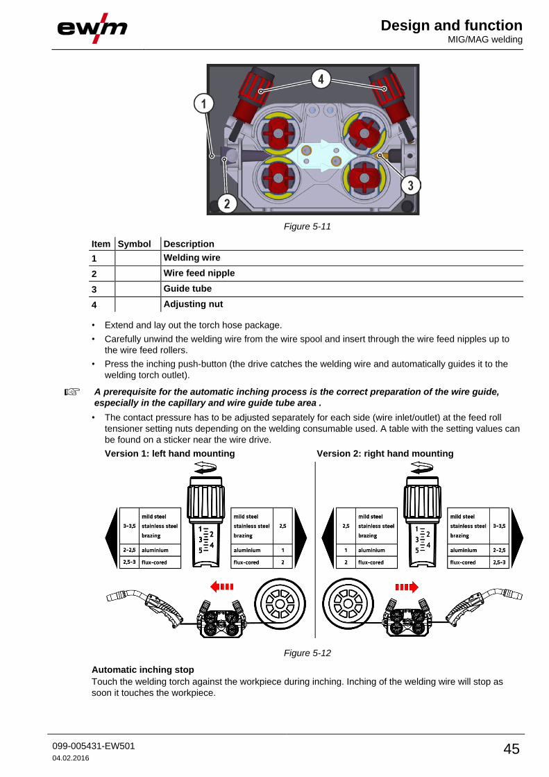
Design and function MIG/MAG welding
099-005431-EW501
04.02.2016 45
Figure 5-11
Item Symbol Description 0
1 Welding wire
2 Wire feed nipple
3 Guide tube
4 Adjusting nut
• Extend and lay out the torch hose package.
• Carefully unwind the welding wire from the wire spool and insert through the wire feed nipples up to
the wire feed rollers.
• Press the inching push-button (the drive catches the welding wire and automatically guides it to the
welding torch outlet).
A prerequisite for the automatic inching process is the correct preparation of the wire guide,
especially in the capillary and wire guide tube area .
• The contact pressure has to be adjusted separately for each side (wire inlet/outlet) at the feed roll
tensioner setting nuts depending on the welding consumable used. A table with the setting values can
be found on a sticker near the wire drive.
Version 1: left hand mounting Version 2: right hand mounting
Figure 5-12
Automatic inching stop
Touch the welding torch against the workpiece during inching. Inching of the welding wire will stop as
soon it touches the workpiece.
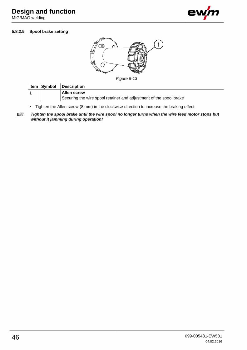
Design and function MIG/MAG welding
46 099-005431-EW501
04.02.2016
5.8.2.5 Spool brake setting
Figure 5-13
Item Symbol Description 0
1 Allen screw
Securing the wire spool retainer and adjustment of the spool brake
• Tighten the Allen screw (8 mm) in the clockwise direction to increase the braking effect.
Tighten the spool brake until the wire spool no longer turns when the wire feed motor stops but
without it jamming during operation!

Design and function MIG/MAG welding
099-005431-EW501
04.02.2016 47
5.8.3 Definition of MIG/MAG welding tasks This machine series offers user-friendly operation and a multitude of features.
• Various welding tasks (JOBs) consisting of welding procedure, material type, wire diameter and
shielding gas type have been predefined .
• The system calculates the required process parameters depending on the operating point specified
(one-dial operation via wire feed speed rotary transducer).
• You can adjust additional parameters in the control configuration menu or using the PC300.NET
welding parameter software, if required.
- See 11.1 JOB-List chapter
5.8.4 Welding task selection
5.8.4.1 Basic welding parameters
You can only change the JOB number when no welding current is flowing.
Operating
element
Action Result Display
1 x
Select JOB list
Set JOB number.
Wait 3s until the setting has been adopted.
5.8.4.2 Operating mode
Operating
element
Action Result Display
n x
Select operating mode
The LED displays the selected operating mode.
Non-latched operation
Latched operation
Green Special non-latched mode
Red Spot operating mode
Special latched mode
No change
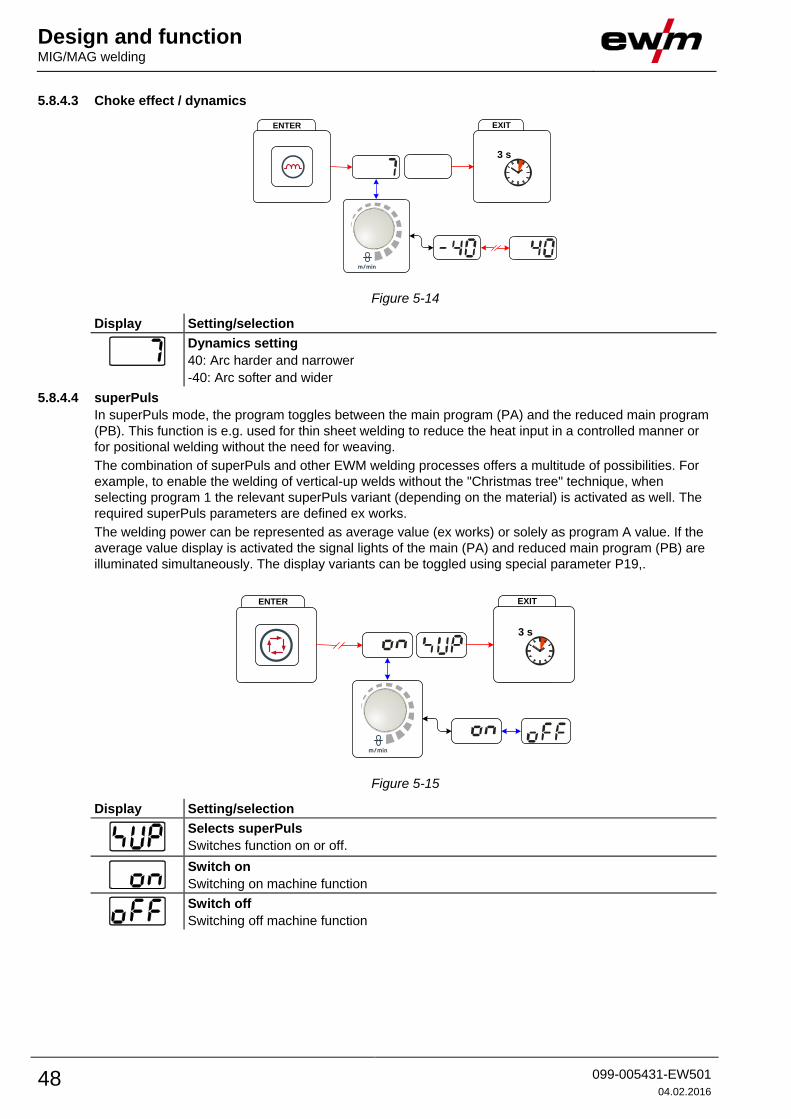
Design and function MIG/MAG welding
48 099-005431-EW501
04.02.2016
5.8.4.3 Choke effect / dynamics
EXITENTER
3 s
Figure 5-14
Display Setting/selection
Dynamics setting
40: Arc harder and narrower
-40: Arc softer and wider
5.8.4.4 superPuls
In superPuls mode, the program toggles between the main program (PA) and the reduced main program
(PB). This function is e.g. used for thin sheet welding to reduce the heat input in a controlled manner or
for positional welding without the need for weaving.
The combination of superPuls and other EWM welding processes offers a multitude of possibilities. For
example, to enable the welding of vertical-up welds without the "Christmas tree" technique, when
selecting program 1 the relevant superPuls variant (depending on the material) is activated as well. The
required superPuls parameters are defined ex works.
The welding power can be represented as average value (ex works) or solely as program A value. If the
average value display is activated the signal lights of the main (PA) and reduced main program (PB) are
illuminated simultaneously. The display variants can be toggled using special parameter P19,.
EXITENTER
3 s
Figure 5-15
Display Setting/selection
Selects superPuls
Switches function on or off.
Switch on
Switching on machine function
Switch off
Switching off machine function

Design and function MIG/MAG welding
099-005431-EW501
04.02.2016 49
5.8.4.5 Burn-back
ENTER
3 s
EXIT
3 s
Figure 5-16
Display Setting/selection
menu burn back
Set burn back
Parameter setting (setting range 0 to 499)
Back-burn set too high: large drops developing on the wire electrode result in poor
ignition properties or the wire electrode sticking to the welding nozzle.
Back-burn set too low: Wire electrode sticks in the molten pool
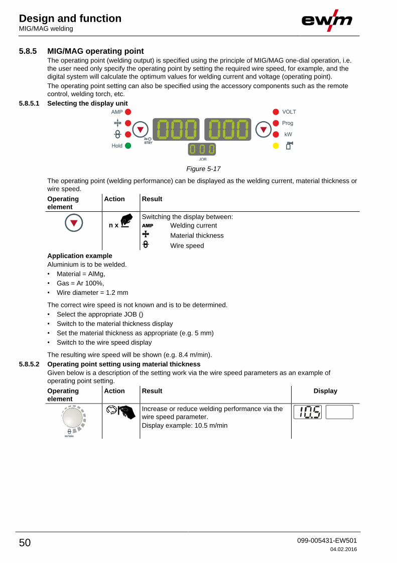
Design and function MIG/MAG welding
50 099-005431-EW501
04.02.2016
5.8.5 MIG/MAG operating point The operating point (welding output) is specified using the principle of MIG/MAG one-dial operation, i.e.
the user need only specify the operating point by setting the required wire speed, for example, and the
digital system will calculate the optimum values for welding current and voltage (operating point).
The operating point setting can also be specified using the accessory components such as the remote
control, welding torch, etc.
5.8.5.1 Selecting the display unit
Figure 5-17
The operating point (welding performance) can be displayed as the welding current, material thickness or
wire speed.
Operating
element
Action Result
n x
Switching the display between:
Welding current
Material thickness
Wire speed
Application example
Aluminium is to be welded.
• Material = AlMg,
• Gas = Ar 100%,
• Wire diameter = 1.2 mm
The correct wire speed is not known and is to be determined.
• Select the appropriate JOB ()
• Switch to the material thickness display
• Set the material thickness as appropriate (e.g. 5 mm)
• Switch to the wire speed display
The resulting wire speed will be shown (e.g. 8.4 m/min).
5.8.5.2 Operating point setting using material thickness
Given below is a description of the setting work via the wire speed parameters as an example of
operating point setting.
Operating
element
Action Result Display
Increase or reduce welding performance via the
wire speed parameter.
Display example: 10.5 m/min
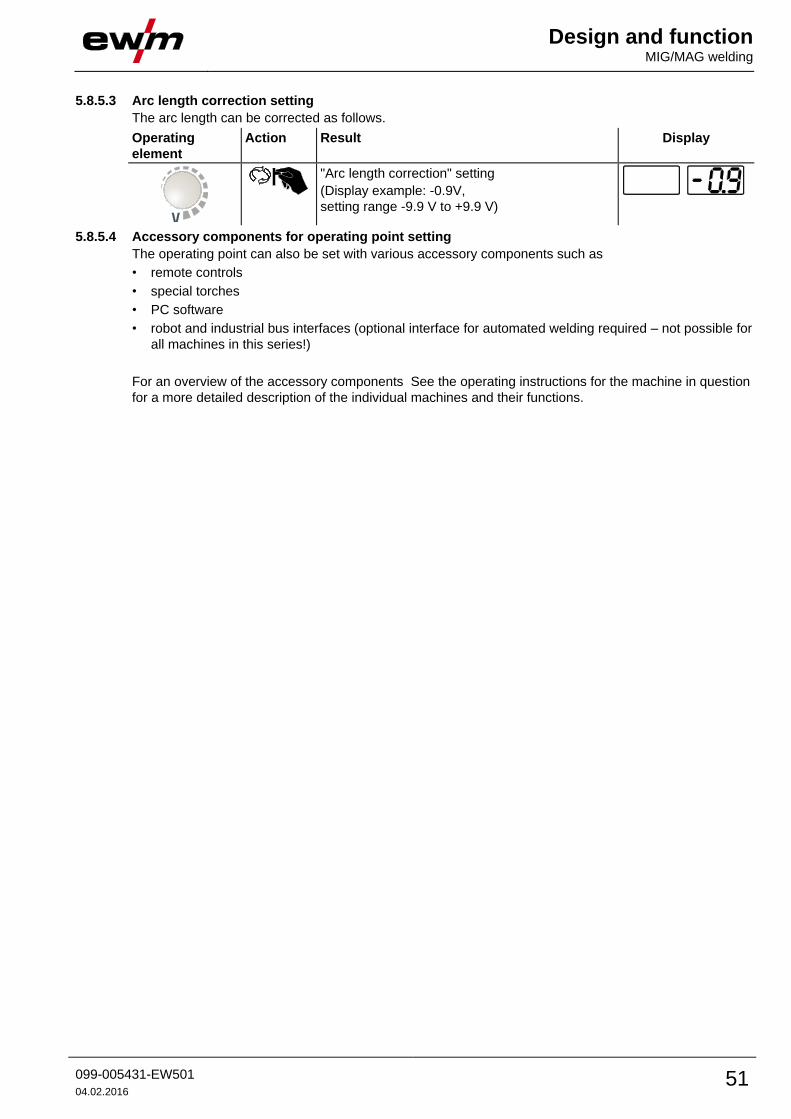
Design and function MIG/MAG welding
099-005431-EW501
04.02.2016 51
5.8.5.3 Arc length correction setting
The arc length can be corrected as follows.
Operating
element
Action Result Display
"Arc length correction" setting
(Display example: -0.9V,
setting range -9.9 V to +9.9 V)
5.8.5.4 Accessory components for operating point setting
The operating point can also be set with various accessory components such as
• remote controls
• special torches
• PC software
• robot and industrial bus interfaces (optional interface for automated welding required – not possible for
all machines in this series!)
For an overview of the accessory components See the operating instructions for the machine in question
for a more detailed description of the individual machines and their functions.
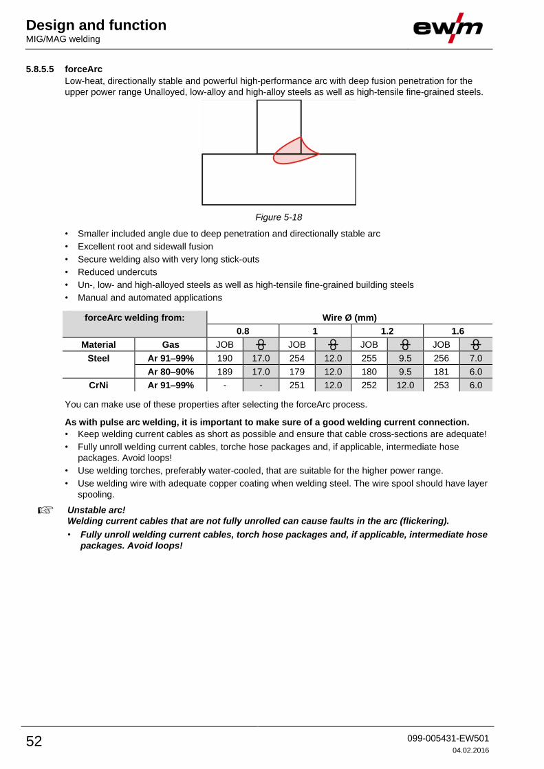
Design and function MIG/MAG welding
52 099-005431-EW501
04.02.2016
5.8.5.5 forceArc
Low-heat, directionally stable and powerful high-performance arc with deep fusion penetration for the
upper power range Unalloyed, low-alloy and high-alloy steels as well as high-tensile fine-grained steels.
Figure 5-18
• Smaller included angle due to deep penetration and directionally stable arc
• Excellent root and sidewall fusion
• Secure welding also with very long stick-outs
• Reduced undercuts
• Un-, low- and high-alloyed steels as well as high-tensile fine-grained building steels
• Manual and automated applications
forceArc welding from: Wire Ø (mm)
0.8 1 1.2 1.6
Material Gas JOB JOB JOB JOB
Steel Ar 91–99% 190 17.0 254 12.0 255 9.5 256 7.0
Ar 80–90% 189 17.0 179 12.0 180 9.5 181 6.0
CrNi Ar 91–99% - - 251 12.0 252 12.0 253 6.0
You can make use of these properties after selecting the forceArc process.
As with pulse arc welding, it is important to make sure of a good welding current connection.
• Keep welding current cables as short as possible and ensure that cable cross-sections are adequate!
• Fully unroll welding current cables, torche hose packages and, if applicable, intermediate hose
packages. Avoid loops!
• Use welding torches, preferably water-cooled, that are suitable for the higher power range.
• Use welding wire with adequate copper coating when welding steel. The wire spool should have layer
spooling.
Unstable arc!
Welding current cables that are not fully unrolled can cause faults in the arc (flickering).
• Fully unroll welding current cables, torch hose packages and, if applicable, intermediate hose
packages. Avoid loops!
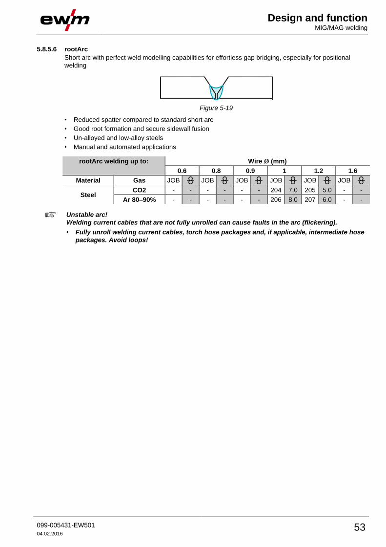
Design and function MIG/MAG welding
099-005431-EW501
04.02.2016 53
5.8.5.6 rootArc
Short arc with perfect weld modelling capabilities for effortless gap bridging, especially for positional
welding
Figure 5-19
• Reduced spatter compared to standard short arc
• Good root formation and secure sidewall fusion
• Un-alloyed and low-alloy steels
• Manual and automated applications
rootArc welding up to: Wire Ø (mm)
0.6 0.8 0.9 1 1.2 1.6
Material Gas JOB JOB JOB JOB JOB JOB
Steel CO2 - - - - - - 204 7.0 205 5.0 - -
Ar 80–90% - - - - - - 206 8.0 207 6.0 - -
Unstable arc!
Welding current cables that are not fully unrolled can cause faults in the arc (flickering).
• Fully unroll welding current cables, torch hose packages and, if applicable, intermediate hose
packages. Avoid loops!
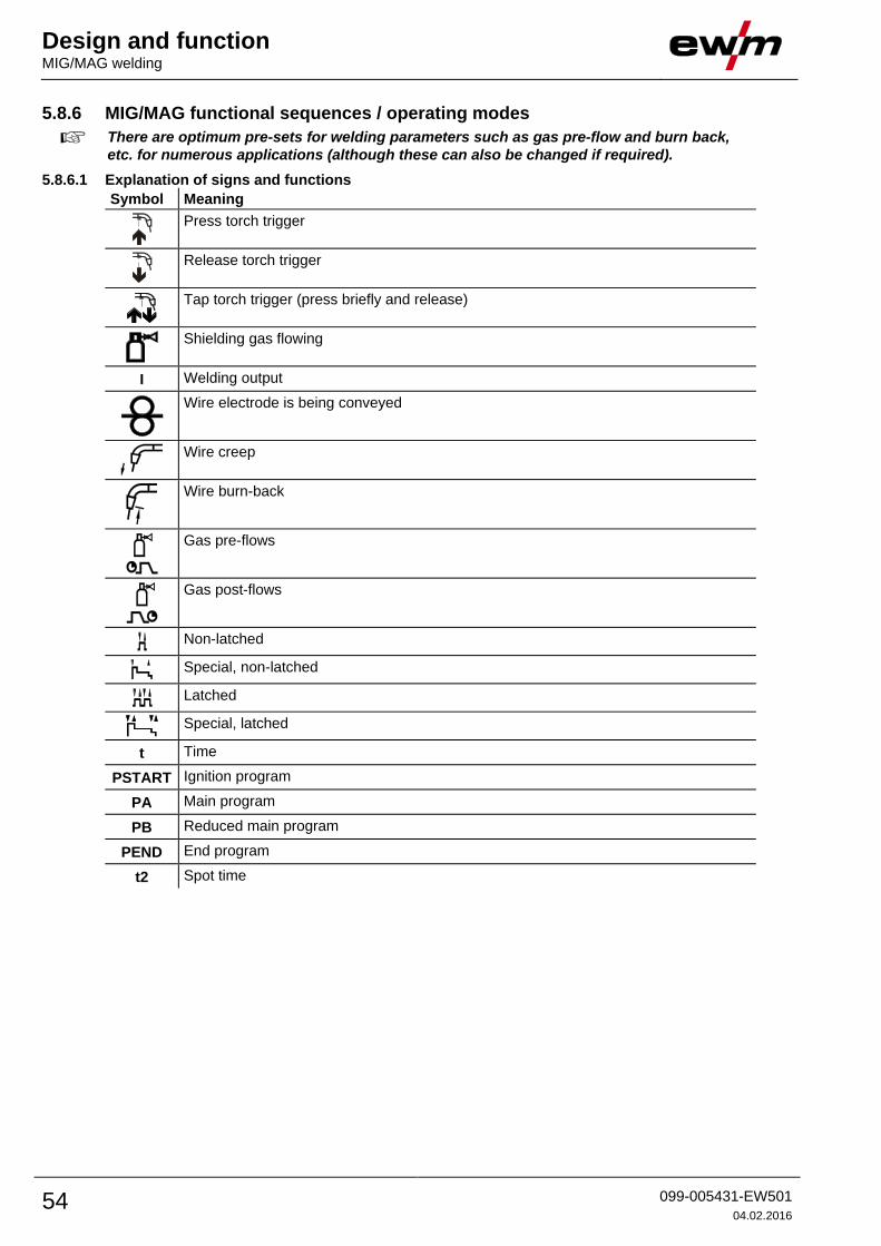
Design and function MIG/MAG welding
54 099-005431-EW501
04.02.2016
5.8.6 MIG/MAG functional sequences / operating modes
There are optimum pre-sets for welding parameters such as gas pre-flow and burn back,
etc. for numerous applications (although these can also be changed if required).
5.8.6.1 Explanation of signs and functions
Symbol Meaning
Press torch trigger
Release torch trigger
Tap torch trigger (press briefly and release)
Shielding gas flowing
I Welding output
Wire electrode is being conveyed
Wire creep
Wire burn-back
Gas pre-flows
Gas post-flows
Non-latched
Special, non-latched
Latched
Special, latched
t Time
PSTART Ignition program
PA Main program
PB Reduced main program
PEND End program
t2 Spot time

Design and function MIG/MAG welding
099-005431-EW501
04.02.2016 55
Non-latched mode
Figure 5-20
Step 1
• Press and hold torch trigger.
• Shielding gas is expelled (gas pre-flows).
• Wire feed motor runs at “creep speed”.
• Arc ignites after the wire electrode makes contact with the workpiece; welding current flows.
• Change over to pre-selected wire speed.
Step 2
• Release torch trigger.
• WF motor stops.
• Arc is extinguished after the preselected wire burn-back time expires.
• Gas post-flow time elapses.
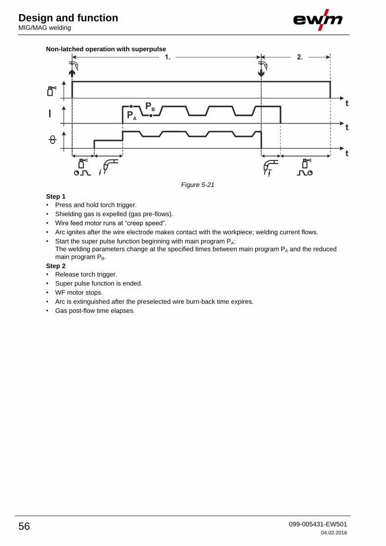
Design and function MIG/MAG welding
56 099-005431-EW501
04.02.2016
Non-latched operation with superpulse
Figure 5-21
Step 1
• Press and hold torch trigger.
• Shielding gas is expelled (gas pre-flows).
• Wire feed motor runs at “creep speed”.
• Arc ignites after the wire electrode makes contact with the workpiece; welding current flows.
• Start the super pulse function beginning with main program PA:
The welding parameters change at the specified times between main program PA and the reduced
main program PB.
Step 2
• Release torch trigger.
• Super pulse function is ended.
• WF motor stops.
• Arc is extinguished after the preselected wire burn-back time expires. • Gas post-flow time elapses.

Design and function MIG/MAG welding
099-005431-EW501
04.02.2016 57
Special, non-latched
Figure 5-22
Step 1
• Press and hold torch trigger
• Shielding gas is expelled (gas pre-flows)
• Wire feed motor runs at “creep speed”.
• Arc ignites after the wire electrode makes contact with the workpiece, welding current is flowing (start
program PSTART for the time tstart)
• Slope to main program PA.
Step 2
• Release torch trigger
• Slope to end program PEND for the time tend.
• WF motor stops.
• Arc is extinguished after the preselected wire burn-back time expires.
• Gas post-flow time elapses.
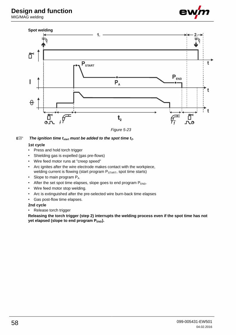
Design and function MIG/MAG welding
58 099-005431-EW501
04.02.2016
Spot welding
Figure 5-23
The ignition time tstart must be added to the spot time t2.
1st cycle
• Press and hold torch trigger
• Shielding gas is expelled (gas pre-flows)
• Wire feed motor runs at "creep speed"
• Arc ignites after the wire electrode makes contact with the workpiece,
welding current is flowing (start program PSTART, spot time starts)
• Slope to main program PA
• After the set spot time elapses, slope goes to end program PEND.
• Wire feed motor stop welding.
• Arc is extinguished after the pre-selected wire burn-back time elapses
• Gas post-flow time elapses.
2nd cycle
• Release torch trigger
Releasing the torch trigger (step 2) interrupts the welding process even if the spot time has not
yet elapsed (slope to end program PEND).

Design and function MIG/MAG welding
099-005431-EW501
04.02.2016 59
Special, non-latched with superpulse
Figure 5-24
Step 1
• Press and hold torch trigger
• Shielding gas is expelled (gas pre-flows)
• Wire feed motor runs at “creep speed”.
• Arc ignites after the wire electrode makes contact with the workpiece, welding current is flowing (start
program PSTART for the time tstart).
• Slope on main program PA.
• Start the super pulse function beginning with main program PA:
The welding parameters change at the specified times between main program PA and the reduced
main program PB.
Step 2
• Release torch trigger
• Super pulse function is ended.
• Slope to end program PEND for the time tend.
• WF motor stops.
• Arc is extinguished after the preselected wire burn-back time expires.
• Gas post-flow time elapses.
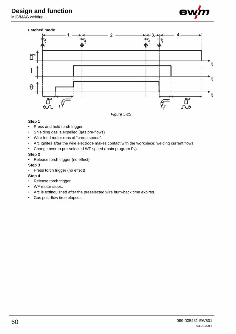
Design and function MIG/MAG welding
60 099-005431-EW501
04.02.2016
Latched mode
Figure 5-25
Step 1
• Press and hold torch trigger
• Shielding gas is expelled (gas pre-flows)
• Wire feed motor runs at “creep speed”.
• Arc ignites after the wire electrode makes contact with the workpiece; welding current flows.
• Change over to pre-selected WF speed (main program PA).
Step 2
• Release torch trigger (no effect)
Step 3
• Press torch trigger (no effect)
Step 4
• Release torch trigger
• WF motor stops.
• Arc is extinguished after the preselected wire burn-back time expires.
• Gas post-flow time elapses.

Design and function MIG/MAG welding
099-005431-EW501
04.02.2016 61
Latched mode with superpulse
Figure 5-26
Step 1:
• Press and hold torch trigger
• Shielding gas is expelled (gas pre-flows)
• Wire feed motor runs at “creep speed”.
• Arc ignites after the wire electrode makes contact with the workpiece; welding current flows.
• Start the super pulse function beginning with main program PA.
The welding parameters change at the specified times between main program PA and the reduced
main program PB.
Step 2:
• Release torch trigger (no effect)
Step 3:
• Press torch trigger (no effect)
Step 4:
• Release torch trigger
• Super pulse function is ended.
• WF motor stops.
• Arc is extinguished after the preselected wire burn-back time expires.
• Gas post-flow time elapses.

Design and function MIG/MAG welding
62 099-005431-EW501
04.02.2016
Latched special
Figure 5-27
Step 1
• Press and hold torch trigger
• Shielding gas is expelled (gas pre-flows)
• Wire feed motor runs at “creep speed”.
• Arc ignites after the wire electrode makes contact with the workpiece, welding current is flowing (start
program PSTART)
Step 2
• Release torch trigger
• Slope to main program PA.
The slope on main program PA is given at the earliest after the set time tSTART elapses and at the
latest when the torch trigger is released.
Tapping1)
can be used to change over to the reduced main program PB.
Repeated tapping will switch back to the main program PA.
Step 3
• Press and hold torch trigger
• Slope to end program PEND.
Step 4
• Release torch trigger
• WF motor stops.
• Arc is extinguished after the preselected wire burn-back time expires.
• Gas post-flow time elapses.
1)
Prevent tapping (brief press and release within 0.3 seconds)
If the welding current is to be prevented from switching over to the reduced main program PB by
tapping, the parameter value for WF3 needs to be set to 100% (PA = PB) in the program sequence.
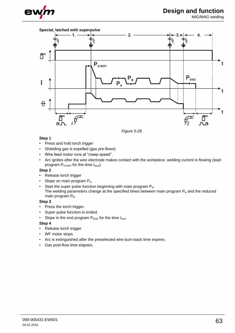
Design and function MIG/MAG welding
099-005431-EW501
04.02.2016 63
Special, latched with superpulse
Figure 5-28
Step 1
• Press and hold torch trigger
• Shielding gas is expelled (gas pre-flows)
• Wire feed motor runs at “creep speed”.
• Arc ignites after the wire electrode makes contact with the workpiece, welding current is flowing (start
program PSTART for the time tstart).
Step 2
• Release torch trigger
• Slope on main program PA.
• Start the super pulse function beginning with main program PA:
The welding parameters change at the specified times between main program PA and the reduced
main program PB.
Step 3
• Press the torch trigger.
• Super pulse function is ended.
• Slope in the end program PEND for the time tend.
Step 4
• Release torch trigger
• WF motor stops.
• Arc is extinguished after the preselected wire burn-back time expires.
• Gas post-flow time elapses.

Design and function MIG/MAG welding
64 099-005431-EW501
04.02.2016
5.8.7 MIG/MAG program sequence ("Program steps" mode) Certain materials, such as aluminium, require special functions in order to be able to weld them safely
and at high quality. The latched special operating mode is used here with the following programs:
• Start program PSTART (reduction of cool points at the start of the seam)
• Main program PA (continuous welding)
• Reduced main program PB (targeted heat reduction)
• End program PEND) (minimisation of end craters via targeted heat reduction)
The programs include the parameters wire speed (operating point), arc length correction, slope times,
program duration, etc.
Figure 5-29
This function can only be enabled with the PC300.NET software.
(See operating instructions for the software)
5.8.7.1 Selection of the program sequence parameter
Operating
Element
Action Result Display
n x
Select parameter in the program sequence
Setting welding parameters

Design and function MIG/MAG welding
099-005431-EW501
04.02.2016 65
5.8.7.2 MIG/MAG overview of parameters
Figure 5-30
Basic Parameters
Item Meaning / Explanation Setting Range
1 1 Gas pre-flow time 0.0s to 20.0s
2 2 PSTART
Wire speed, relative
Arc length correction
1% to 200%
-9.9V to +9.9V
3 3 Duration 0.0s to 20.0s
4 4 Slope duration from PSTART to PA 0.0s to 20.0s
5 5 PA
Wire speed, absolute
0.1 m/min to 40 m/min
6 7 Duration (spot time and superpulse) 0.01s to 20.0s
7 8 PB
Wire speed, relative
Arc length correction, relative
1% to 200%
-9.9V to +9.9V
8 9 Duration 0.01s to 20.0s
9 1
0
Slope duration from PA to PEND 0.0s to 20s
10 1
1
PEND
Wire speed, relative
Arc length correction
1% to 200%
-9.9V to +9.9V
11 1
2
Duration (superpulse) 0.0s to 20s
12 1
3
Gas post-flow time 0.0s to 20s
13 1
4
superPuls On / Off
PSTART, PB, and PEND are set as relative programs ex faxtory. They relate to percentages of the wire
feed value of the main program PA. These programs can also be set in an absolute manner, if
desired (see Setting of special parameter P21).

Design and function MIG/MAG welding
66 099-005431-EW501
04.02.2016
5.8.7.3 Example, tack welding (non-latched)
Figure 5-31
Basic parameters
Parameter Meaning / explanation Setting range
GASstr Gas pre-flow time 0.0s to 20.0s
GASend: Gas post-flow time 0.0s to 20s
RUECK Wire burn-back length 2 to 500
"PA" main program
Parameter Meaning / explanation Setting range
Setting the wire speed
5.8.7.4 Example, aluminium tack welding (non-latched special)
Figure 5-32
Basic parameters
Welding parameter Meaning / explanation Setting range
GASstr Gas pre-flow time 0.0s to 20.0s
GASend: Gas post-flow time 0.0s to 20.0s
RUECK Wire burn-back length 2 to 500
"PSTART" start program
Welding parameter Meaning / explanation Setting range
DVstart Wire speed 0% to 200%
Ustart Arc length correction -9.9V to +9.9V
tstart Duration 0.0s to 20s
"PA" main program
Welding parameter Meaning / explanation Setting range
Setting the wire speed
"PEND" end-crater program
Welding parameter Meaning / explanation Setting range
DVend Wire speed 0% to 200%
Uend Arc length correction -9.9V to +9.9V
tend Duration 0.0s to 20s

Design and function MIG/MAG welding
099-005431-EW501
04.02.2016 67
5.8.7.5 Example, aluminium welding (latched special)
Figure 5-33
Basic parameters
Welding parameter Meaning / explanation Setting range
GASstr Gas pre-flow time 0.0s to 20.0s
GASend: Gas post-flow time 0.0s to 20.0s
RUECK Wire burn-back length 2 to 500
"PSTART" start program
Welding parameter Meaning / explanation Setting range
DVstart Wire speed 0% to 200%
ustart Arc length correction -9.9V to +9.9V
tstart Duration 0.0s to 20s
"PA" main program
Welding parameter Meaning / explanation Setting range
Setting the wire speed
"PB" reduced main program
Welding parameter Meaning / explanation Setting range
DV3 Wire speed 0% to 200%
U3 Arc length correction -9.9V to +9.9V
"PEND" end-crater program
Welding parameter Meaning / explanation Setting range
tSend Slope duration from PA or PB to PEND 0.0s to 20s
DVend Wire speed 0% to 200%
Uend Arc length correction -9.9V to +9.9V
tend Duration 0.0s to 20s

Design and function MIG/MAG welding
68 099-005431-EW501
04.02.2016
5.8.7.6 Example, visible seams (latched super pulse)
Figure 5-34
Basic parameters
Welding parameter Meaning / explanation Setting range
GASstr Gas pre-flow time 0.0s to 20.0s
GASend: Gas post-flow time 0.0s to 20.0s
RUECK Wire burn-back length 2 to 500
"PSTART" start program
Welding parameter Meaning / explanation Setting range
DVstart Wire speed 0% to 200%
ustart Arc length correction -9.9V to +9.9V
tstart Duration 0.0s to 20s
"PA" main program
Welding parameter Meaning / explanation Setting range
tS1 Slope duration from PSTART to PA 0.0s to 20s
DV3 Setting the wire speed 0% to 200%
t2 Duration 0.1s to 20s
tS3 Slope duration from PB to PA 0.0s to 20s
"PB" reduced main program
Welding parameter Meaning / explanation Setting range
tS2 Slope duration from PA to PB 0.0s to 20s
DV3 Wire speed 0% to 200%
U3 Arc length correction -9.9V to +9.9V
t3 Duration 0.1s to 20s
"PEND" end-crater program
Welding parameter Meaning / explanation Setting range
tSend Slope duration from PA or PB to PEND 0.0s to 20s
DVend Wire speed 0% to 200%
Uend Arc length correction -9.9V to +9.9V
tend Duration 0.0s to 20s

Design and function MIG/MAG welding
099-005431-EW501
04.02.2016 69
5.8.8 Main program A mode Different welding tasks or positions on a workpiece demand various welding performances (operating
points) or welding programs. The following parameters are stored in each of the up to 16 programs:
• Operating mode
• Welding type
• superPuls (ON/OFF)
• Wire feed speed (DV2)
• Voltage correction (U2)
• Dynamics (DYN2)
The user can change the main program welding parameters using the following components.
Pro
gra
m
sw
itc
hin
g
JO
B s
wit
ch
ing
Pro
gra
m
Op
era
tin
g m
od
e
su
pe
rPu
ls
Wir
e s
pee
d
Vo
lta
ge
co
rre
cti
on
Dy
nam
ics
M3.7x
Wire feeder control Yes Yes P0
Yes Yes Yes
P1...15 Yes
R20
Remote control Yes No P0
No Yes
No P1...9 Yes
1)
R40
Remote control Yes No P0 No Yes Yes
No No
R50
Remote control Yes No P0
Yes Yes P1...15
PC 300.NET
Software No No P0 Yes No
P1...15 Yes
Up/Down
Welding torch Yes No P0
No Yes
No P1...9 No
2 Up/Down
Welding torch Yes No P0
No Yes
No P1...15 No
PC 1
Welding torch Yes No P0
No Yes
No P1...15 No
PC 2
Welding torch Yes Yes P0
No Yes
No P1...15 No
1) in case of correction mode, refer to Special parameters "P7 – correction mode, limit value setting"

Design and function MIG/MAG welding
70 099-005431-EW501
04.02.2016
Example 1: Welding workpieces with different sheet metal thicknesses (non-latched)
Figure 5-35
Example 2: Welding different positions on a workpiece (latched)
Figure 5-36
Example 3: Aluminium welding of different sheet metal thicknesses (non-latched or latched
special)
Figure 5-37
Up to 16 programs (PA0 to PA15) can be defined.
An operating point (wire speed, arc length correction, dynamics/choke effect) can be defined
permanently in each program.
Program P0 is an exception: the settings for operating points are made manually here.
Changes to the welding parameters are saved immediately!

Design and function MIG/MAG welding
099-005431-EW501
04.02.2016 71
5.8.8.1 Selecting parameters (program A)
Changes to the welding parameters can only be made when the key switch is in position "1".
Operating
element
Action Result Display
n x
Change welding data display over to program
display.
(LED Prog is on)
Select program number.
Display example: Program "1".
n x
Select program sequence parameter
"Main program (PA)".
(LED is on)
Set wire speed.
(Absolute value)
Set arc length correction.
Display example: "-0.8 V" correction
(Setting range: -9.9 V to +9.9 V)
1 x
Select "Dynamic" program sequence parameter.
Set dynamic. (Setting range 40 to -40)
40: Arc hard and narrow.
-40: Arc soft and wide.
5.8.9 MIG/MAG automatic cut-out
The welding machine ends the ignition process or the welding process with an
• ignition fault (no welding current flows within 5 s after the start signal)
• arc interruption (arc is intrerrupted for longer than 5 s)

Design and function MIG/MAG welding
72 099-005431-EW501
04.02.2016
5.8.10 Standard MIG/MAG torch The MIG welding torch trigger is essentially used to start and stop the welding process.
Operating elements Functions
Torch trigger • Start/stop welding
Other functions are also possible by tapping the torch trigger, depending on the machine type
and control configuration- See 5.15 Special parameters (advanced settings) chapter:
• Change over between welding programs (P8).
• Program selection before starting welding (P17).
• Switching between wire feed units in dual operation mode (P10).
5.8.11 MIG/MAG special-torches
Function specifications and more indepth information can be found in the operating manual for
the relevant welding torch!
5.8.11.1 Program- and Up- / down operation
Figure 5-38
Item Symbol Description 0
1
Welding torch function changeover switch (special welding torch required)
Changing over programs or JOBs
Infinite adjustment of welding performance.
5.8.11.2 Switching between Push/Pull and intermediate drive
DANGER
Do not carry out any unauthorised repairs or modifications!
To avoid injury and equipment damage, the unit must only be repaired or modified by
specialist, skilled persons!
The warranty becomes null and void in the event of unauthorised interference.
• Appoint only skilled persons for repair work (trained service personnel)!
CAUTION
Test!
Before re-commissioning, it is essential that an "inspection and test during operation"
is carried out conforming to IEC / DIN EN 60974-4 "Arc welding devices - inspection and
testing during operation"!
• For detailed instructions, please see the standard operating instructions for the welding
machine.
The plugs are located directly on the M3.7x printed circuit board.
Plug Function
on X24 Operation with Push/Pull welding torch (factory setting)
on X23 Operation with intermediate drive
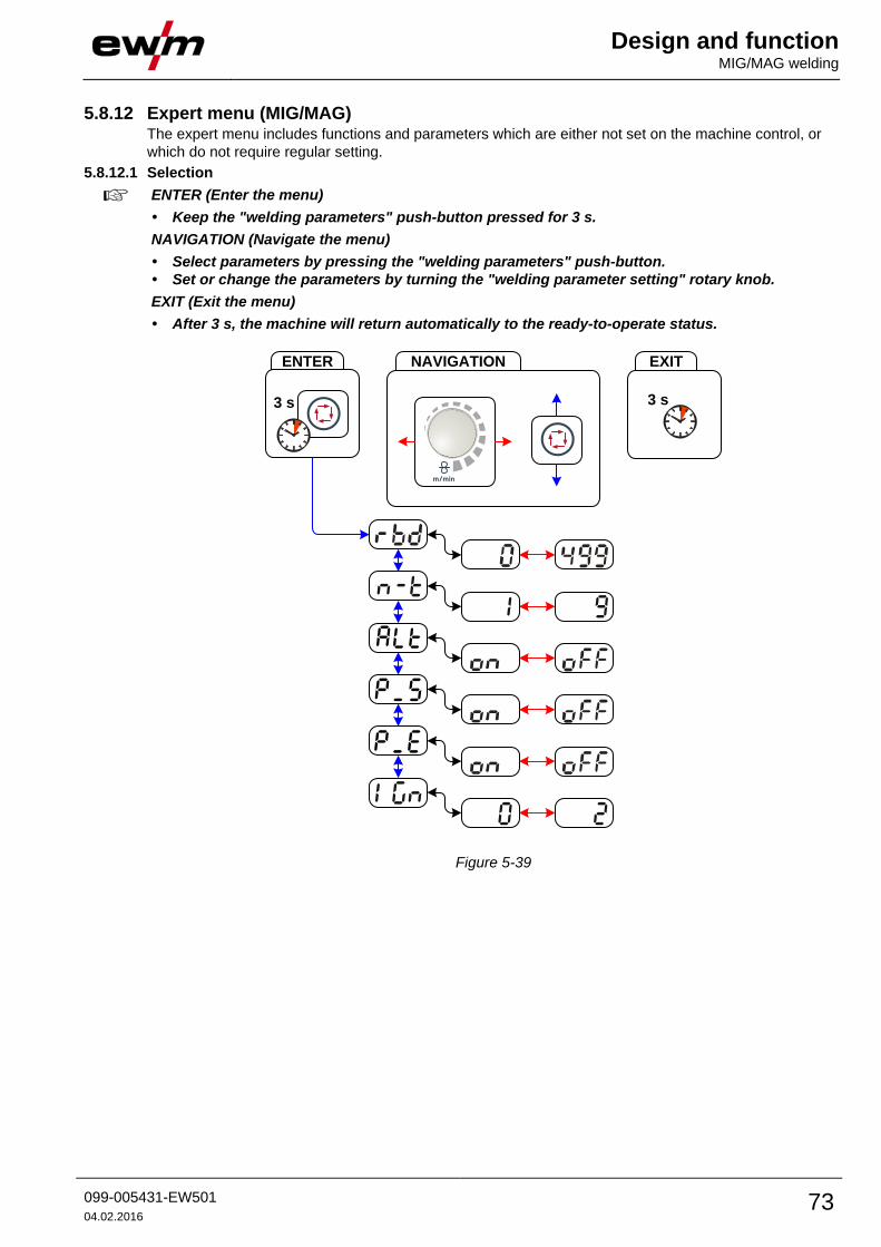
Design and function MIG/MAG welding
099-005431-EW501
04.02.2016 73
5.8.12 Expert menu (MIG/MAG) The expert menu includes functions and parameters which are either not set on the machine control, or
which do not require regular setting.
5.8.12.1 Selection
ENTER (Enter the menu)
• Keep the "welding parameters" push-button pressed for 3 s.
NAVIGATION (Navigate the menu)
• Select parameters by pressing the "welding parameters" push-button.
• Set or change the parameters by turning the "welding parameter setting" rotary knob.
EXIT (Exit the menu)
• After 3 s, the machine will return automatically to the ready-to-operate status.
EXIT
3 s
ENTER
3 s
NAVIGATION
Figure 5-39
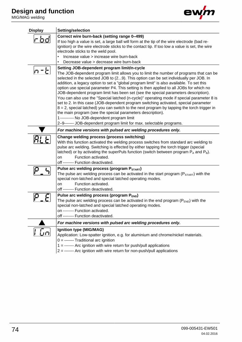
Design and function MIG/MAG welding
74 099-005431-EW501
04.02.2016
Display Setting/selection
Correct wire burn-back (setting range 0–499)
If too high a value is set, a large ball will form at the tip of the wire electrode (bad re-
ignition) or the wire electrode sticks to the contact tip. If too low a value is set, the wire
electrode sticks to the weld pool.
• Increase value > increase wire burn-back
• Decrease value > decrease wire burn-back
Setting JOB-dependent program limit/n-cycle
The JOB-dependent program limit allows you to limit the number of programs that can be
selected in the selected JOB to (2...9). This option can be set individually per JOB. In
addition, a legacy option to set a "global program limit" is also available. To set this
option use special parameter P4. This setting is then applied to all JOBs for which no
JOB-dependent program limit has been set (see the special parameters description).
You can also use the "Special latched (n-cycle)" operating mode if special parameter 8 is
set to 2. In this case (JOB-dependent program switching activated, special parameter
8 = 2, special latched) you can switch to the next program by tapping the torch trigger in
the main program (see the special parameters description).
1 ---------- No JOB-dependent program limit
2–9 ------- JOB-dependent program limit for max. selectable programs.
For machine versions with pulsed arc welding procedures only.
Change welding process (process switching)
With this function activated the welding process switches from standard arc welding to
pulse arc welding. Switching is effected by either tapping the torch trigger (special
latched) or by activating the superPuls function (switch between program PA and PB).
on Function activated.
off -------- Function deactivated.
Pulse arc welding process (program PSTART)
The pulse arc welding process can be activated in the start program (PSTART) with the
special non-latched and special latched operating modes.
on Function activated.
off -------- Function deactivated.
Pulse arc welding process (program PEND)
The pulse arc welding process can be activated in the end program (PEND) with the
special non-latched and special latched operating modes.
on -------- Function activated.
off -------- Function deactivated.
For machine versions with pulsed arc welding procedures only.
Ignition type (MIG/MAG)
Application: Low-spatter ignition, e.g. for aluminium and chrome/nickel materials.
0 = ------- Traditional arc ignition
1 = ------- Arc ignition with wire return for push/pull applications
2 = ------- Arc ignition with wire return for non-push/pull applications

Design and function TIG welding
099-005431-EW501
04.02.2016 75
5.9 TIG welding 5.9.1 Welding torch and workpiece line connection
Figure 5-40
Item Symbol Description 0
1
Workpiece
2
Connection socket, "+" welding current
• TIG welding: Workpiece connection
3
Welding torch
4 Welding torch hose package
5 Welding torch connection (Euro or Dinse torch connector)
Welding current, shielding gas and torch trigger integrated
6 Welding current cable, polarity selection
Welding current to the central connector/torch, enables polarity selection.
• TIG: Connection socket for “-” welding current
7
Quick connect coupling (red)
coolant return
8
Quick connect coupling (blue)
coolant supply
• Insert the central plug for the welding torch into the central connector and screw together with crown
nut.
• Insert the cable plug on the work piece lead into the "+" welding current connection socket and lock by
turning to the right.
• Welding current lead, insert polarity selection into the "-" welding current connection socket and lock.
Where applicable:
• Lock connecting nipples of the cooling water tubes into the corresponding quick connect couplings:
Return line red to quick connect coupling, red (coolant return) and
supply line blue to quick connect coupling, blue (coolant supply).

Design and function TIG welding
76 099-005431-EW501
04.02.2016
5.9.2 Welding task selection • Select JOB 127 (TIG welding task).
It is only possible to change the JOB number when no welding current is flowing.
Operating
element
Action Result Display
1 x
Select JOB number input
Set the JOB number
The machine adopts the required setting after
approx. 3 seconds
5.9.3 Welding current setting The welding current is normally set using the "Wire speed" rotary dial.
Operating
element
Action Result Displays
Welding current is set Setpoint setting
5.9.4 TIG arc ignition
5.9.4.1 Liftarc ignition
Figure 5-41
The arc is ignited on contact with the workpiece:
a) Carefully place the torch gas nozzle and tungsten electrode tip onto the workpiece and press the torch
trigger (liftarc current flowing, regardless of the main current set).
b) Incline the torch over the torch gas nozzle to produce a gap of approx. 2-3 mm between the electrode
tip and the workpiece. The arc ignites and the welding current is increased, depending on the
operating mode set, to the ignition or main current set.
c) Lift off the torch and swivel to the normal position.
Ending the welding process: Release or press the torch trigger depending on the operating mode
selected.
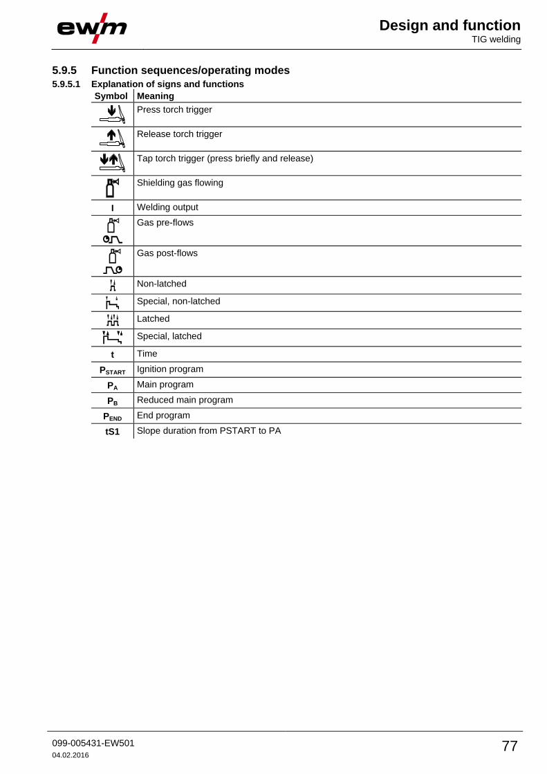
Design and function TIG welding
099-005431-EW501
04.02.2016 77
5.9.5 Function sequences/operating modes
5.9.5.1 Explanation of signs and functions
Symbol Meaning
Press torch trigger
Release torch trigger
Tap torch trigger (press briefly and release)
Shielding gas flowing
I Welding output
Gas pre-flows
Gas post-flows
Non-latched
Special, non-latched
Latched
Special, latched
t Time
PSTART Ignition program
PA Main program
PB Reduced main program
PEND End program
tS1 Slope duration from PSTART to PA
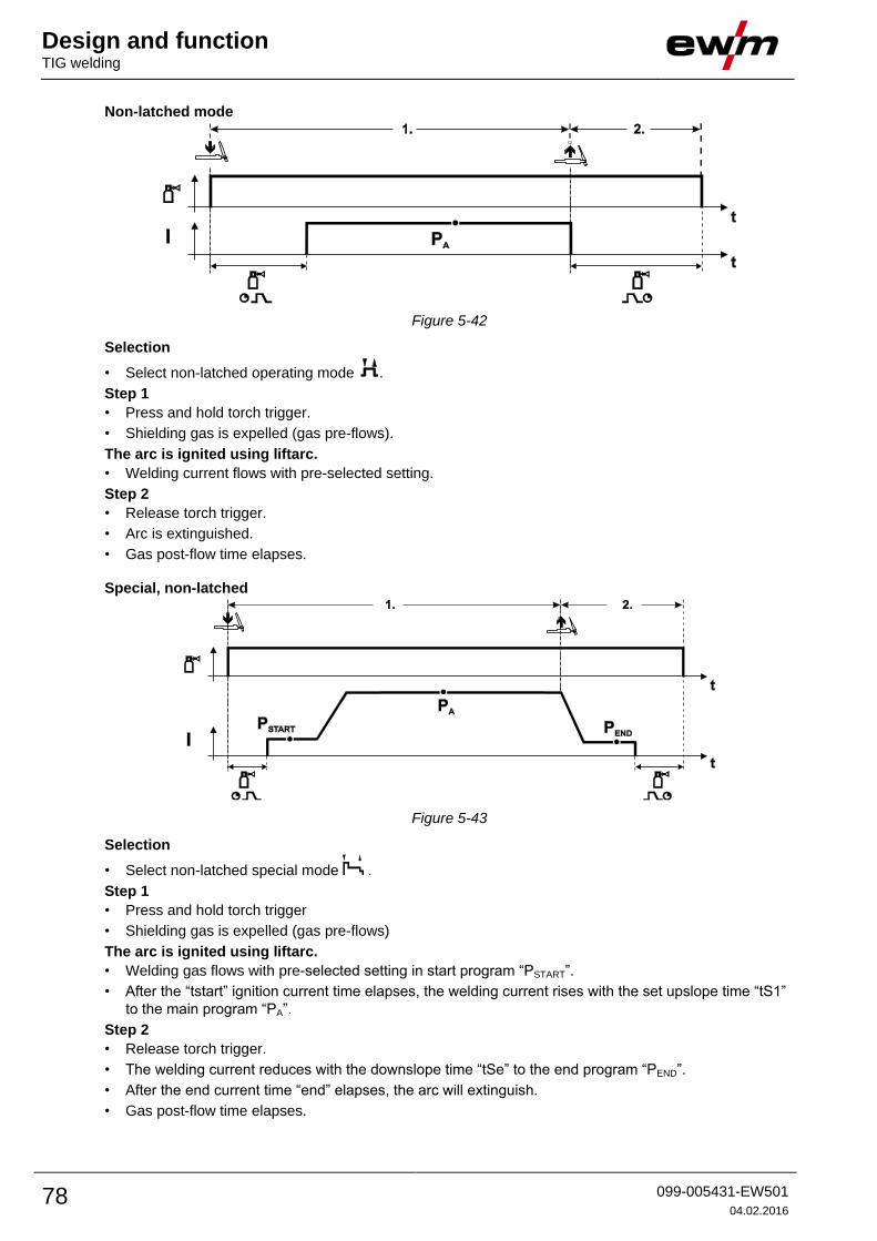
Design and function TIG welding
78 099-005431-EW501
04.02.2016
Non-latched mode
Figure 5-42
Selection
• Select non-latched operating mode .
Step 1
• Press and hold torch trigger.
• Shielding gas is expelled (gas pre-flows).
The arc is ignited using liftarc.
• Welding current flows with pre-selected setting.
Step 2
• Release torch trigger.
• Arc is extinguished.
• Gas post-flow time elapses.
Special, non-latched
Figure 5-43
Selection
• Select non-latched special mode .
Step 1
• Press and hold torch trigger
• Shielding gas is expelled (gas pre-flows)
The arc is ignited using liftarc.
• Welding gas flows with pre-selected setting in start program “PSTART”.
• After the “tstart” ignition current time elapses, the welding current rises with the set upslope time “tS1”
to the main program “PA”.
Step 2
• Release torch trigger.
• The welding current reduces with the downslope time “tSe” to the end program “PEND”.
• After the end current time “end” elapses, the arc will extinguish.
• Gas post-flow time elapses.

Design and function TIG welding
099-005431-EW501
04.02.2016 79
Latched mode
Figure 5-44
Selection
• Select latched operating mode .
Step 1
• Press and hold torch trigger
• Shielding gas is expelled (gas pre-flows)
The arc is ignited using liftarc.
• Welding current flows with pre-selected setting.
Step 2
• Release torch trigger (no effect)
Step 3
• Press torch trigger (no effect)
Step 4
• Release torch trigger
• Arc is extinguished.
• Gas post-flow time elapses.

Design and function TIG welding
80 099-005431-EW501
04.02.2016
Latched special
Figure 5-45
Selection
• Select latched special mode .
Step 1
• Press and hold torch trigger.
• Shielding gas is expelled (gas pre-flows).
The arc is ignited using liftarc.
• Welding gas flows at pre-selected setting in start program "PSTART".
Step 2
• Release torch trigger.
• Slope on main program "PA".
The slope on main program PA is given at the earliest after the set time tSTART elapses and at the
latest when the torch trigger is released.
Tapping can be used to switch to the reduced main program "PB". Repeated tapping will switch
back to the main program "PA".
Step 3
• Press the torch trigger.
• Slope to end program "PEND".
Step 4
• Release torch trigger.
• Arc is extinguished.
• Gas post-flow time elapses.
5.9.6 TIG automatic cut-out
The welding machine ends the ignition process or the welding process with an
• ignition fault (no welding current flows within 5 s after the start signal)
• arc interruption (arc is intrerrupted for longer than 5 s)

Design and function TIG welding
099-005431-EW501
04.02.2016 81
5.9.7 TIG program sequence ("Program steps" mode)
Figure 5-46
Basic parameters
Item Meaning/explanation Setting range
1 Gas pre-flow time 0 s to 0.9 s
2 PSTART
Ignition current
0% to 200%
3 Duration (start program) 0 s to 20 s
4 Slope duration from PSTART to PA 0 s to 20 s
5 PA (main program)
Welding current, absolute
5 A to 550 A
6 Duration (PA) 0.01 s to 20.0 s
7 PB (reduced main program)
Welding current
1% to 100%
8 Duration (reduced main program) 0.01 s to 20.0 s
9 Slope duration from PA to PEND 0 s to 20 s
10 PEND (end program)
Welding current
1% to 100%
11 Duration (end program) 0 s to 20 s
12 Gas post-flow time 0 s to 20 s
13 superPuls on/off
PSTART, PB, and PEND are relative programs whose welding current settings are a percentage based on the
general welding current setting.

Design and function MMA welding
82 099-005431-EW501
04.02.2016
5.10 MMA welding
CAUTION
Risk of being crushed or burnt.
When replacing spent or new stick electrodes
• Switch off machine at the main switch
• Wear appropriate safety gloves
• Use insulated tongs to remove spent stick electrodes or to move welded workpieces and
• Always put the electrode holder down on an insulated surface.
5.10.1 Connecting the electrode holder and workpiece lead
Figure 5-47
Item Symbol Description 0
1
Workpiece
2
Electrode holder
3
Connection socket, “-” welding current
4
Connection socket, “+” welding current
• Insert cable plug of the electrode holder into either the "+" or "-" welding current connection socket and
lock by turning to the right.
• Insert cable plug of the workpiece lead into either the "+" or "-" welding current connection socket and
lock by turning to the right.
Polarity depends on the instructions from the electrode manufacturer given on the electrode
packaging.

Design and function MMA welding
099-005431-EW501
04.02.2016 83
5.10.2 Welding task selection • Select JOB 128 (MMA welding task).
It is only possible to change the JOB number when no welding current is flowing.
Operating
element
Action Result Display
1 x
Select JOB number input
Set the JOB number
The machine adopts the required setting after
approx. 3 seconds
5.10.3 Welding current setting The welding current is normally set using the "Wire speed" rotary dial.
Operating
element
Action Result Displays
Welding current is set Setpoint setting
5.10.4 Arcforce Operating
element
Action Result Display
Select arcforcing welding parameter
LED for the button is on.
Arcforcing setting for electrode types:
(Setting range -40 to 40)
Negative values Rutile
Values around zero Basic
Positive values Cellulose

Design and function MMA welding
84 099-005431-EW501
04.02.2016
5.10.5 Hotstart The hotstart device improves the ignition of the stick electrodes using an increased ignition current.
a) = Hotstart time
b) = Hotstart current
I = Welding current
t = Time
Figure 5-48
For hotstart parameter settings, - See 5.10.7 Parameter overview chapter
5.10.6 Antistick
Anti-stick prevents the electrode from annealing.
If the electrode sticks in spite of the Arcforce device, the machine
automatically switches over to the minimum current within about 1
second to prevent the electrode from overheating. Check the welding
current setting and correct according to the welding task!
Figure 5-49
5.10.7 Parameter overview
Figure 5-50
Basic parameters
Item Meaning/explanation Setting range
1 Welding current 5 A to maximum welding current
2 Hotstart time 0 to 20 s
3 Hotstart current 0 to 200 %
The hotstart current is a percentage based on the welding current selected.
Design and function Remote control
099-005431-EW501
04.02.2016 85
5.11 Remote control
CAUTION
Damage due to the use of non-genuine parts!
The manufacturer's warranty becomes void if non-genuine parts are used!
• Only use system components and options (power sources, welding torches, electrode
holders, remote controls, spare parts and replacement parts, etc.) from our range of
products!
• Only insert and lock accessory components into the relevant connection socket when the
machine is switched off.
The remote controls are operated via the 19-pole remote control connection socket (analogue) or
the 7-pole remote control connection socket (digital), depending on the model.
Please note the relevant documentation of the accessory components.
5.12 Interfaces for automation
DANGER
Do not carry out any unauthorised repairs or modifications!
To avoid injury and equipment damage, the unit must only be repaired or modified by
specialist, skilled persons!
The warranty becomes null and void in the event of unauthorised interference.
• Appoint only skilled persons for repair work (trained service personnel)!
CAUTION
Damage due to incorrect connection!
Accessory components and the power source itself can be damaged by incorrect
connection!
• Only insert and lock accessory components into the relevant connection socket when the
machine is switched off.
• Comprehensive descriptions can be found in the operating instructions for the relevant
accessory components.
• Accessory components are detected automatically after the power source is switched on.
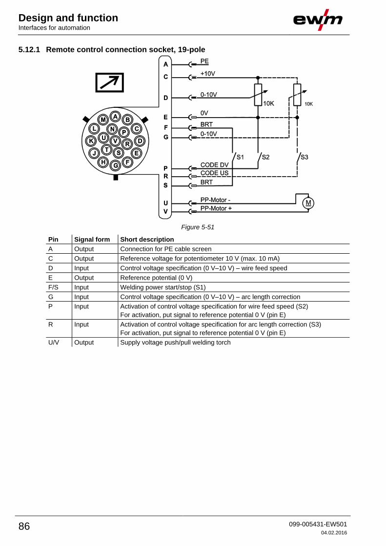
Design and function Interfaces for automation
86 099-005431-EW501
04.02.2016
5.12.1 Remote control connection socket, 19-pole
Figure 5-51
Pin Signal form Short description
A Output Connection for PE cable screen
C Output Reference voltage for potentiometer 10 V (max. 10 mA)
D Input Control voltage specification (0 V–10 V) – wire feed speed
E Output Reference potential (0 V)
F/S Input Welding power start/stop (S1)
G Input Control voltage specification (0 V–10 V) – arc length correction
P Input Activation of control voltage specification for wire feed speed (S2)
For activation, put signal to reference potential 0 V (pin E)
R Input Activation of control voltage specification for arc length correction (S3)
For activation, put signal to reference potential 0 V (pin E)
U/V Output Supply voltage push/pull welding torch
Design and function PC Interfaces
099-005431-EW501
04.02.2016 87
5.13 PC Interfaces
CAUTION
Equipment damage or faults may occur if the PC is connected incorrectly!
Not using the SECINT X10USB interface results in equipment damage or faults in signal
transmission. The PC may be destroyed due to high frequency ignition pulses.
• Interface SECINT X10USB must be connected between the PC and the welding machine!
• The connection must only be made using the cables supplied (do not use any additional
extension cables)!
PC 300 welding parameter software
Create all welding parameters quickly on the PC and easily transfer them to one or more welding
machines (accessories: set consisting of software, interface, connection leads).
Q-DOC 9000 welding data documentation software
(Accessories: set consisting of software, interface, connection leads)
The ideal tool for welding data documentation of, for example:
welding voltage and current, wire speed and motor current.
WELDQAS welding data monitoring and documentation system
Network-compatible welding data monitoring and documentation system for digital machines
5.14 Protecting welding parameters from unauthorised access
The key switch is only available for machines which are fitted with the "OW KL XX5" option ex
works.
To protect against unauthorised or unintentional adjustment of the welding parameters on the machine,
the control input can be locked with the aid of a key switch.
In key switch position 1 all functions and parameters can be set without restriction.
In key switch position 0 the following functions and parameters cannot be changed:
• No adjustment of the operating point (welding performance) in programs 1–15.
• No change of welding or operating mode in programs 1–15.
• The welding parameters can be displayed but not changed in the control's function sequence.
• No welding task switching (JOB block operation P16 possible).
• No change of special parameters (except P10). Restart required.

Design and function Special parameters (advanced settings)
88 099-005431-EW501
04.02.2016
5.15 Special parameters (advanced settings) Special parameters (P1 to Pn) are applied for customer-specific configuration of machine functions. This
allows the user maximum flexibility in optimising their requirements.
These settings are not configured directly on the machine control since a regular setting of the
parameters is generally not required. The number of selectable special parameters can deviate between
the machine controls used in the welding system (also see the relevant standard operating instructions).
If required, the special parameters can be reset to the factory settings- See 5.15.1.1 Reset to factory
settings chapter.
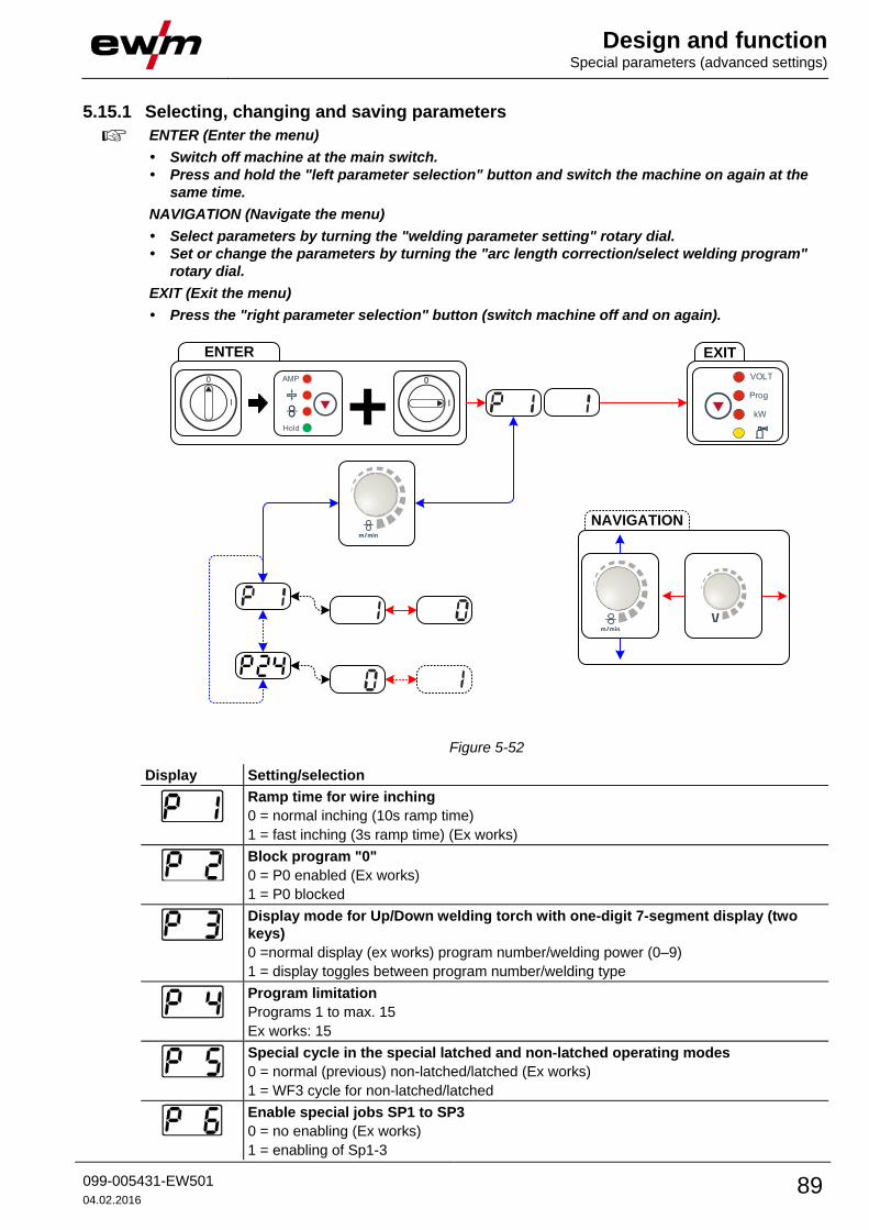
Design and function Special parameters (advanced settings)
099-005431-EW501
04.02.2016 89
5.15.1 Selecting, changing and saving parameters
ENTER (Enter the menu)
• Switch off machine at the main switch.
• Press and hold the "left parameter selection" button and switch the machine on again at the
same time.
NAVIGATION (Navigate the menu)
• Select parameters by turning the "welding parameter setting" rotary dial.
• Set or change the parameters by turning the "arc length correction/select welding program"
rotary dial.
EXIT (Exit the menu)
• Press the "right parameter selection" button (switch machine off and on again).
ENTER
+EXIT
NAVIGATION
l
0 AMP
Hold
Prog
VOLT
kW
Figure 5-52
Display Setting/selection
Ramp time for wire inching
0 = normal inching (10s ramp time)
1 = fast inching (3s ramp time) (Ex works)
Block program "0"
0 = P0 enabled (Ex works)
1 = P0 blocked
Display mode for Up/Down welding torch with one-digit 7-segment display (two
keys)
0 = normal display (ex works) program number/welding power (0–9)
1 = display toggles between program number/welding type
Program limitation
Programs 1 to max. 15
Ex works: 15
Special cycle in the special latched and non-latched operating modes
0 = normal (previous) non-latched/latched (Ex works)
1 = WF3 cycle for non-latched/latched
Enable special jobs SP1 to SP3
0 = no enabling (Ex works)
1 = enabling of Sp1-3

Design and function Special parameters (advanced settings)
90 099-005431-EW501
04.02.2016
Display Setting/selection
Correction operation, threshold value setting
0 = correction operation switched off (Ex works)
1 = correction operation on
"Main program (PA)" flashing
Program changeover with standard torch
0 = no program changeover (Ex works)
1 = special latched
2 = specific latched special (n cycle active)
Lat. and sp. lat. tapping start
0 = no latched tapping start (Ex works)
1 = latched tapping start possible
One or two-wire feed operation
0 = single operation (Ex works)
1 = dual operation, this unit is the "master"
2 = dual operation, this unit is the "slave"
Special latched tapping time
0 = tapping function switched off
1 = 300ms (Ex works)
2 = 600ms
JOB list changeover
0 = task-oriented JOB list
1 = actual JOB list (Ex works)
2 = actual JOB list, JOB changeover activated via accessories
Lower limit remote JOB changeover
Lowest JOB that can be selected using PowerControl 2 torches.
Lower limit: 129 (Ex works)
Upper limit remote JOB changeover
JOB range of the POWERCONTROL2 torch
Upper limit: 169 (Ex works)
HOLD function
0 = HOLD values are not displayed
1 = HOLD values are displayed (Ex works)
Block JOB mode
0 = Block JOB mode not enabled (Ex works)
1 = Block JOB mode enabled
Program selection with standard torch trigger
0 = no program selection (Ex works)
1 = program selection possible
Switching the operating mode and welding type using the wire feed control
0 = Switching the operating mode and welding type using the wire feed control and
program 0 (factory setting).
1 = Switching the operating mode and welding type using the wire feed control and
programs 0-15.
Mean value display for superPuls
0 = ------- Function switched off.
1 = Function switched on (ex factory).
Predefined pulse arc welding process in the PA program
0 = ------- Predefined pulse arc welding process in the PA program is disabled.
1 = ------- If the superPuls and welding process switching functions are available and
activated, the pulse arc welding process is always executed in the main
program PA (ex factory).
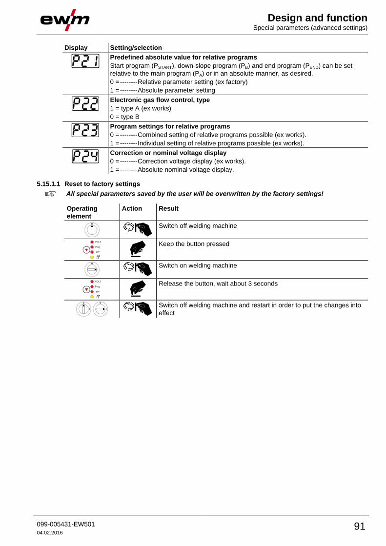
Design and function Special parameters (advanced settings)
099-005431-EW501
04.02.2016 91
Display Setting/selection
Predefined absolute value for relative programs
Start program (PSTART), down-slope program (PB) and end program (PEND) can be set
relative to the main program (PA) or in an absolute manner, as desired.
0 = -------- Relative parameter setting (ex factory)
1 = -------- Absolute parameter setting
Electronic gas flow control, type
1 = type A (ex works)
0 = type B
Program settings for relative programs
0 = -------- Combined setting of relative programs possible (ex works).
1 = -------- Individual setting of relative programs possible (ex works).
Correction or nominal voltage display
0 = -------- Correction voltage display (ex works).
1 = -------- Absolute nominal voltage display.
5.15.1.1 Reset to factory settings
All special parameters saved by the user will be overwritten by the factory settings!
Operating
element
Action Result
Switch off welding machine
Keep the button pressed
Switch on welding machine
Release the button, wait about 3 seconds
Switch off welding machine and restart in order to put the changes into
effect

Design and function Special parameters (advanced settings)
92 099-005431-EW501
04.02.2016
5.15.1.2 Special parameters in detail
Ramp time for wire inching (P1)
The wire inching starts with a speed 1.0 m/min for 2 secs. It is subsequently increased to a ramp function
to 6.0 m/min. The ramp time can be set between two ranges.
During wire inching, the speed can be changed by means of the welding parameter setting rotary dial.
Changing the speed has no effect on the ramp time.
Program "0", releasing the program block (P2)
The program P0 (manual setting) is blocked. Only operation with P1-P15 is possible, irrespective of the
key switch position.
Display mode for Up/Down welding torch with one-digit 7-segment display (P3)
Normal display:
• Program mode: Program number
• Up/down operation: Welding power (0=minimum current/9=maximum current)
Toggling display:
• Program mode: Program number and welding procedure (P=pulse/n=not pulse) are toggled
• Up/down operation: Welding power (0=minimum current/9=maximum current) and symbol for up/down
operation are toggled
Program limit (P4)
Program selection can be limited with the special parameter P4.
• The setting is adopted for all JOBs.
• Program selection depends on the position of the "welding torch function" changeover switch (see
"Machine description"). Programs can only be switched when the changeover switch is in the
"program" position.
• Programs can be switched by means of a connected remote control or special welding torch.
• If a special welding torch or a remote control is not connected, it is only possible to switch programs by
means of the "arc length correction/select welding program" rotary dial (see "Machine description").
Special cycle in the operating modes special latched and non-latched (P5)
With the special sequence activated, the start of the welding process changes as follows:
Sequence for special non-latched mode/special latched mode:
• Start program "PSTART"
• Main program "PA"
Sequence for special non-latched mode/special latched mode with custom sequence activated:
• Start program "PSTART"
• Reduced main program "PB"
• Main program "PA"
Enabling special JOBs SP1 to SP3 (P6)
Phoenix Expert machine series:
The welding task is set at the power source control; refer to the relevant system documentation.
If required, the predefined special welding tasks SP1 = JOB 129 / SP2 = JOB130 / SP3 = JOB 131 only
can be selected at the wire feeder control. The special JOBs are selected by pressing the welding task
selection push-button for a longer period. The special JOBs are switched by pressing the push-button
briefly.
The JOB changeover is blocked if the key switch is in the “0” position.
This block can be cancelled for the special JOBs (SP1 - SP3).

Design and function Special parameters (advanced settings)
099-005431-EW501
04.02.2016 93
Correction operation, threshold value setting (P7)
The correction operation is switched on and off for all JOBs and their programs at the same time. A
correction operation is specified for wire speed (DV) and welding voltage correction (Ukorr) for each JOB.
The correction value is saved separately for each program. The correction range can be maximum 30%
of the wire speed and +/-9.9 V welding voltage.
Figure 5-53
Example for the operating point in correction mode:
The wire speed in one program (1 to 15) is set on 10.0 m/min.
This corresponds to a welding voltage (U) of 21,9 V. When the key switch is set to "0" position, welding in
this program can only be carried out with these values.
To allow the welder also to perform wire and voltage correction in program mode, the correction mode
must be switched on and limit values for wire and voltage must be specified.
Setting of the correction limit value = WFlimit = 20% / Ulimit = 1.9 V
Now the wire speed can be corrected by 20% (8.0 up to 12.0 m/min) and the welding voltage by +/-1.9 V
(3.8 V).
In the example the wire speed is set on 11.0 m/min. This corresponds to a welding voltage of 22 V
Now the welding voltage can be corrected by further 1.9 V (20.1 V and 23.9 V).
The values for voltage and wire-speed correction will be reset if the key switch is moved to the "1"
setting.
Setting the correction range:
• Switch on the "Correction operation" special parameter (P7=1) and save the setting.
- See 5.16.1 Selecting, changing and saving parameters chapter
• Key switch to position "1".
• Set correction range according to the following table:

Design and function Special parameters (advanced settings)
94 099-005431-EW501
04.02.2016
Operating
element
Action Result Display (examples)
Left Right
x
n
Press button until "PROG" LED comes
on.
Left: Wire feed speed
Right: Program number
4 s
Press button and hold down for approx.
4 s
Left: Current limit value of the wire
feed speed correction
Right: Current limit value of the
voltage correction
Set limit value for the wire feed speed
correction
Set limit value for voltage correction
After approx. 5 s without further user intervention, the set values are
adopted and the display switches back to the program display,
• Key switch back to position "0"!
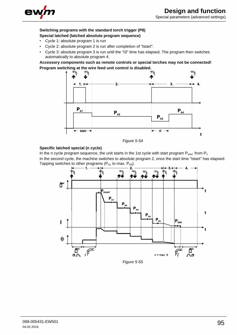
Design and function Special parameters (advanced settings)
099-005431-EW501
04.02.2016 95
Switching programs with the standard torch trigger (P8)
Special latched (latched absolute program sequence)
• Cycle 1: absolute program 1 is run
• Cycle 2: absolute program 2 is run after completion of "tstart".
• Cycle 3: absolute program 3 is run until the "t3" time has elapsed. The program then switches
automatically to absolute program 4.
Accessory components such as remote controls or special torches may not be connected!
Program switching at the wire feed unit control is disabled.
Figure 5-54
Specific latched special (n cycle)
In the n cycle program sequence, the unit starts in the 1st cycle with start program Pstart from P1
In the second cycle, the machine switches to absolute program 2, once the start time "tstart" has elapsed.
Tapping switches to other programs (PA1 to max. PA9).
Figure 5-55

Design and function Special parameters (advanced settings)
96 099-005431-EW501
04.02.2016
The number of programs (PAn) corresponds to the cycle number specified under N cycle.
1st cycle
• Press and hold torch trigger.
• Shielding gas is expelled (gas pre-flows).
• Wire feed motor runs at "creep speed".
• Arc ignites after the wire electrode makes contact with the workpiece, welding current is flowing (start
program PSTART from PA1)
2nd cycle
• Release torch trigger.
• Slope to main program PA1.
The slope to main program PA1 is given at the earliest after the set time tSTART elapses and at the
latest when the torch trigger is released. Tapping (pressing briefly and releasing within 0.3 sec)
can switch to other programs. Programs PA1 to PA9 are possible.
3rd cycle
• Press and hold torch trigger.
• Slope to end program PEND from PAN. The program can be stopped at any time by pressing the torch
trigger longer than 0.3 sec. PEND from PAN is then executed.
4th cycle
• Release torch trigger.
• WF motor stops.
• Arc is extinguished after the pre-selected wire burn-back time elapses.
• Gas post-flow time elapses.
Latched/special-latched tap start (P9)
In latched – tap start – operating mode it is possible to switch straight to the second step by tapping the
torch trigger; it is not necessary for current to be flowing.
The welding can be halted by pressing the torch trigger for a second time.

Design and function Special parameters (advanced settings)
099-005431-EW501
04.02.2016 97
"Single or dual operation" (P10) setting
If the system is fitted with two wire feeds, no further accessory components may be operated on
the 7-pole connection socket (digital)!
This relates to digital remote controls, robot interfaces, documentation interfaces, welding
torches with digital control lead connection, etc.
No second wire feed may be connected in single operation (P10 = 0)!
• Remove connections to the second wire feed
In dual operation (P10 = 1 or 2), both wire feed units must be connected and configured differently
on the controls for this operating mode!
• Configure one wire feed unit as the master (P10 = 1)
• Configure the other wire feed unit as a slave (P10 = 2)
Wire feed units with key switches (optional, - See 5.14 Protecting welding parameters from
unauthorised access chapter) must be configured as masters (P10 = 1).
The wire feed configured as the master is active after the welding machine is switched on. There
are no other functional differences between the wire feeds.
Latched special tapping time setting (P11)
The tapping time for changing over between the main program and reduced main program can be set in
three levels.
0 = no tapping
1 = 320ms (factory setting)
2 = 640ms
JOB list switching (P12)
Value Designation Explanation
0 Task-oriented
JOB list
The JOB numbers are sorted by welding wires and shielding gases.
JOB numbers may be skipped during selection where relevant.
1 Actual JOB list JOB numbers correspond to the actual memory cells. Each JOB can be
selected; no memory cells are skipped during selection.
2 Actual JOB list,
JOB changeover active
As for the actual JOB list. JOB changeover is also possible with
accessory components, such as the PowerControl 2 torch.

Design and function Special parameters (advanced settings)
98 099-005431-EW501
04.02.2016
Creating user-defined JOB lists
A consecutive memory range where accessories such as the POWERCONTROL 2 torch can be
used to switch between JOBs will be created.
• Set special parameter P12 to "2".
• Set "Program or Up/Down function" changeover switch to "Up/Down" position.
• Select an existing JOB which is closest to the required result.
• Copy JOB to one or more target JOB numbers.
If any JOB parameters need to be changed, select the target JOBs in sequence and change the
parameters individually.
• Set special parameter P13 to the lower limit and
• Set special parameter P14 to the upper limit of the target JOBs.
• Set "Program or Up/Down function" changeover switch to "Program" position.
JOBs can be changed over in the specified range using the accessory component.
Copying JOBs, "Copy to" function
The possible target range is between 129 - 169.
• First configure special parameter P12 to P12 = 2 or P12 = 1!
Operating
element
Action Result Display
1 x
JOB list selection
Source JOB selection
- - Wait for approx. 3 s for the JOB to be applied
1 x
Keep the push-button pressed for approx. 5 s
Copy setting to function ("Copy to")
Source JOB number selection
1 x
Save
The JOB is copied to the new target
By repeating the last two steps the same source JOB can be copied to several target JOBs.
If the control detects user inactivity for more than 5 s, it switches to parameter display again and the copy
operation is finished.

Design and function Special parameters (advanced settings)
099-005431-EW501
04.02.2016 99
Lower and upper limits of the remote JOB changeover process (P13, P14)
The highest and lowest JOB numbers which can be selected using accessory components, such as the
PowerControl 2 torch.
Avoids an accidental changeover into undesirable or undefined JOBs.
Hold function (P15)
Hold function active (P15 = 1)
• Mean values for the last main program parameters used for welding are displayed.
Hold function not active (P15 = 0)
• Setpoint values for the main program parameters are displayed.
Block JOB mode (P16)
The following accessory components support block JOB mode:
• Up/Down welding torch with one-digit 7-segment display (two keys)
Program 0 is always active in JOB 0 and program 1 in all other JOBs
In this operating mode, a total of 27 JOBs (welding tasks) divided into three blocks can be called up using
accessory components.
The following settings must be made in order to be able to use block JOB mode:
• Switch the "Program or Up/Down function" changeover switch to "Program"
• Set the JOB list to actual JOB list (special parameter P12 = "1")
• Enable block JOB mode (special parameter P16 = "1")
• Change to block JOB mode by selecting one of the special JOBs 129, 130 or 131.
Simultaneous operation with interfaces such as RINT X12, BUSINT X11, DVINT X11 or digital
accessory components such as is the R40 remote control is not possible!
Allocation of JOB numbers to the display on the accessory components
JOB no. Display/selection on the accessory component
0 1 2 3 4 5 6 7 8 9
Special JOB 1 129 141 142 143 144 145 146 147 148 149
Special JOB 2 130 151 152 153 154 155 156 157 158 159
Special JOB 3 131 161 162 163 164 165 166 167 168 169
JOB 0:
This JOB allows you to set the welding parameters manually.
Selection of JOB 0 can be prevented via the key switch or with the "block program 0" parameter (P2).
Key switch position 0, or special parameter P2 = 0: JOB 0 is blocked.
Key switch position 1, or special parameter P2 = 1: JOB 0 can be selected.
JOBs 1-9:
Nine JOBs can be called up in each special JOB (see table).
Nominal values for wire speed, arc correction, dynamics etc must be defined in advance in these JOBs.
This can be done easily with the PC300.NETsoftware.
If the software is not available, user-defined JOB lists can be created in the special JOB areas with the
"Copy to" function. (See explanations about this in the "Switching JOB lists (P12)" chapter)
Design and function Special parameters (advanced settings)
100 099-005431-EW501
04.02.2016
Selecting programs with the standard torch trigger (P17)
Allows you to select a program or switch a program before starting welding.
You switch to the next program by tapping the torch trigger. Once the last enabled program is reached,
you start again at the beginning.
• Program 0 is the first enabled program, provided that it is not blocked.
(see also special parameter P2).
• The last enabled program is P15.
- If the programs are not limited by special parameter P4 (see special parameter P4).
- Or if the programs are limited for the selected JOB by the n cycle setting (see parameter P8).
• Welding starts when the torch trigger is held for longer than 0.64 s.
You can select programs with the standard torch trigger in all operating modes (non-latched, special non-
latched. latched and special latched).
Switching the operating mode and welding type using the wire feed control (P18)
Selecting the operating mode (non-latched, latched, etc.) and welding type (MIG/MAG standard
welding/pulse arc welding) at the wire feed unit control or the welding machine control.
• P18 = 0
- Program 0: To select the operating mode and welding type at the wire feed unit.
- Program 1-15: To select the operating mode and welding type at the welding machine.
• P18 = 1
- Program 0-15: To select the operating mode and welding type at the wire feed unit.
Mean value display for superPuls (P19)
Function active (P19 = 1)
• For superPuls, the performance mean value from program A (PA) and program B (PB) is shown on the
display (ex factory).
Function inactive (P19 = 0)
• Only the performance of program A is displayed for superPuls.
If the function is enabled and only "000" is shown on the machine display, this is a rare case of
an incompatible system set-up. Solution: Disable special parameter P19.
Predefined execution of the pulsed arc welding process in the PA program (P20)
For machine versions with pulsed arc welding procedures only.
Function active (P20 = 1)
• If the superPuls and welding process switching functions are available and activated, the pulse arc
welding process is always executed in the main program PA (ex factory).
Function inactive (P20 = 0)
• Predefined execution of the pulse arc welding process in the PA program is disabled.

Design and function Special parameters (advanced settings)
099-005431-EW501
04.02.2016 101
Predefined absolute value for relative programs (P21)
Start program (PSTART), down-slope program (PB) and end program (PEND) can be set relative to the main
program (PA) or in an absolute manner, as desired.
Function active (P21 = 1)
• Absolute parameter setting
Function inactive (P21 = 0)
• Relative parameter setting (ex factory)
Electronic gas flow control, type (P22)
Active only in machines with integrated gas flow control (option ex works).
Adjustment may only be carried out by authorised service personnel (basic setting = 1).
Program settings for relative programs (P23)
The start, down-slope and end program relative programs can be set individually or combined for the P0-
P15 operating points. When choosing the combined setting, in contrast to the individual setting, the
parameter values are saved in the JOB With the individual setting, the parameter values are identical for
all JOBs (except for special JOBs SP1,SP2 and SP3).
Correction or nominal voltage display (P24)
When setting the arc correction using the right-hand rotary knob the display will either show the correction
voltage +- 9.9 V (ex works) or the absolute nominal voltage.
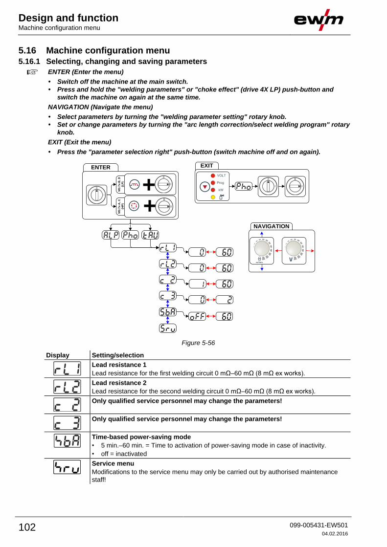
Design and function Machine configuration menu
102 099-005431-EW501
04.02.2016
5.16 Machine configuration menu 5.16.1 Selecting, changing and saving parameters
ENTER (Enter the menu)
• Switch off the machine at the main switch.
• Press and hold the "welding parameters" or "choke effect" (drive 4X LP) push-button and
switch the machine on again at the same time.
NAVIGATION (Navigate the menu)
• Select parameters by turning the "welding parameter setting" rotary knob.
• Set or change parameters by turning the "arc length correction/select welding program" rotary
knob.
EXIT (Exit the menu)
• Press the "parameter selection right" push-button (switch machine off and on again).
ENTER EXIT
NAVIGATION
l
0l
0
Prog
VOLT
kW+M3.7
x-B
, D
(LP
)
+M3
.7x
-A, C
(HP
)
Figure 5-56
Display Setting/selection
Lead resistance 1
Lead resistance for the first welding circuit 0 mΩ–60 mΩ (8 mΩ ex works).
Lead resistance 2
Lead resistance for the second welding circuit 0 mΩ–60 mΩ (8 mΩ ex works).
Only qualified service personnel may change the parameters!
Only qualified service personnel may change the parameters!
Time-based power-saving mode
• 5 min.–60 min. = Time to activation of power-saving mode in case of inactivity.
• off = inactivated
Service menu
Modifications to the service menu may only be carried out by authorised maintenance
staff!

Design and function Machine configuration menu
099-005431-EW501
04.02.2016 103
5.16.2 Aligning the cable resistance The resistance value of cables can either be set directly or it can be aligned using the power source. The
factory setting of the power sources is 8 mΩ. This value correponds to a 5 m earth cable, a 1.5 m
intermediate hose package and a 3 m water-cooled welding torch. With other hose package lengths, it is
necessary to carry out a +/- voltage correction to optimise welding properties. The voltage correction
value can be set close to zero by means of realigning the cable resistance. It is recommended to align the
electric cable resistance after replacing accessories such as torches or intermediate hose packages.
In case a second wire feeder is used the (rL2) parameter has to be aligned. For all other configurations it
is sufficient to align the (rL1) parameter.
2
3
4
1
l
0
50mml
0
m/min
B
A
+
+
M3
.7x
-B, D
(L
P)
M3
.7x
-A, C
(H
P)
Figure 5-57

Design and function Machine configuration menu
104 099-005431-EW501
04.02.2016
1 Preparation
• Switch off the welding machine.
• Unscrew the gas nozzle from the welding torch.
• Trim the welding wire, so that it is flush with the contact tip.
• Retract the welding wire a little (approx. 50 mm) on the wire feeder. There should now be no more
welding wire in the contact tip.
2 Configuration
• Press the "welding parameter or choke effect" push-button while simultaneously switching on the
welding machine. Release push-button.
• "Welding parameter" push-button on the M3.7x-A and M3.7x-C control.
• "Choke effect" push-button on the M3.7x-B and M3.7x-D control.
• The required parameter can now be selected using the 'Welding parameter setting' rotary knob.
Parameter rL1 must be aligned for all machine combinations. In case of welding systems with a
second power circuit – if two wire feeders are to be operated from a single power source, for example
– a second alignment with parameter rL2 must be performed.
3 Alignment/measurement
• Applying slight pressure, put the welding torch in place with the contact tip on a clean, purged location
on the workpiece and then press the torch trigger for approx. 2 seconds. A short-circuit current will
flow briefly, which is used to determine and display the cable resistance. The value can be between
0 mΩ and 40 mΩ. The new value is immediately saved without requiring further confirmation. If no
value is shown on the right-hand display, then measurement failed. The measurement must be
repeated.
4 Restoring welding standby mode
• Switch off the welding machine.
• Screw the gas nozzle onto the welding torch.
• Switch on the welding machine
• Insert the welding wire.
5.16.3 Power-saving mode (Standby) You can activate the power-saving mode by either pressing the push-button for a prolonged time or by
setting a parameter in the machine configuration menu (time-controlled power-saving mode).
When power-saving mode is activated, the machine displays show the horizontal digit in the
centre of the display only.
Pressing any operating element (e.g. tapping the torch trigger) deactivates power-saving mode and the
machine is ready for welding again.
- See 5.16 Machine configuration menu chapter
- See 5.16 Machine configuration menu chapter
Maintenance, care and disposal General
099-005431-EW501
04.02.2016 105
6 Maintenance, care and disposal
DANGER
Improper maintenance and testing
The equipment may only be cleaned, repaired or tested by specialist, skilled persons! A
skilled person is one who, due to training, knowledge and experience, is able to
recognise the dangers that can occur during testing of this equipment as well as
possible subsequent damage and who is able to implement the required safety
procedures.
• Complete all tests given in the chapter below!
• Only put the equipment back into operation following a successful test.
Risk of injury from electric shock!
Cleaning machines that are not disconnected from the mains can lead to serious
injuries!
• Disconnect the machine completely from the mains.
• Remove the mains plug!
• Wait for 4 minutes until the capacitors have discharged!
Repair and maintenance work may only be performed by qualified authorised personnel; otherwise the
right to claim under warranty is void. In all service matters, always consult the dealer who supplied the
machine. Return deliveries of defective equipment subject to warranty may only be made through your
dealer. When replacing parts, use only original spare parts. When ordering spare parts, please quote the
machine type, serial number and item number of the machine, as well as the type designation and item
number of the spare part.
6.1 General When used in the specified environmental conditions and under normal operating conditions, this
machine is largely maintenance-free and requires a minimum of care.
There are some points, which should be observed, to guarantee fault-free operation of your welding
machine. Among these are regular cleaning and checking as described below, depending on the pollution
level of the environment and the length of time the unit is in use.
6.2 Maintenance work, intervals 6.2.1 Daily maintenance tasks
• Check that all connections and wearing parts are hand-tight and tighten if necessary.
• Check that all screw and plug connections and replaceable parts are secured correctly, tighten if
necessary.
• Remove any spatter.
• Clean the wire feed rollers on a regular basis (depending on the degree of soiling).
6.2.1.1 Visual inspection
• Check hose package and power connections for exterior damage and replace or have repaired by
specialist staff as necessary!
• Mains supply lead and its strain relief
• Gas tubes and their switching equipment (solenoid valve)
• Other, general condition
6.2.1.2 Functional test
• Check correct mounting of the wire spool.
• Welding current cables (check that they are fitted correctly and secured)
• Gas cylinder securing elements
• Operating, message, safety and adjustment devices (Functional test)

Maintenance, care and disposal Disposing of equipment
106 099-005431-EW501
04.02.2016
6.2.2 Monthly maintenance tasks
6.2.2.1 Visual inspection
• Casing damage (front, rear and side walls)
• Wheels and their securing elements
• Transport elements (strap, lifting lugs, handle)
• Check coolant tubes and their connections for impurities
6.2.2.2 Functional test
• Selector switches, command devices, emergency stop devices, voltage reducing devices, message
and control lamps
• Check that the wire guide elements (inlet nipple, wire guide tube) are fitted securely.
6.2.3 Annual test (inspection and testing during operation)
The welding machine may only be tested by competent, capable personsl. A capable person is
one who, because of his training, knowledge and experience, is able to recognise the dangers
that can occur while testing welding power sources as well as possible subsequent damage and
who is able to implement the required safety procedures.
For more information refer to the "Warranty registration" brochure supplied and our information
regarding warranty, maintenance and testing at www.ewm-group.com!
A periodic test according to IEC 60974-4 "Periodic inspection and test" has to be carried out. In addition
to the regulations on testing given here, the relevant local laws and regulations must also be observed.
6.3 Disposing of equipment
Proper disposal!
The machine contains valuable raw materials, which should be recycled, and electronic
components, which must be disposed of.
• Do not dispose of in household waste!
• Observe the local regulations regarding disposal!
6.3.1 Manufacturer's declaration to the end user • According to European provisions (guideline 2002/96/EG of the European Parliament and the Council
of January, 27th 2003), used electric and electronic equipment may no longer be placed in unsorted
municipal waste. It must be collected separately. The symbol depicting a waste container on wheels
indicates that the equipment must be collected separately.
This machine is to be placed for disposal or recycling in the waste separation systems provided for
this purpose.
• According to German law (law governing the distribution, taking back and environmentally correct
disposal of electric and electronic equipment (ElektroG) from 16.03.2005), used machines are to be
placed in a collection system separate from unsorted municipal waste. The public waste management
utilities (communities) have created collection points at which used equipment from private
households can be disposed of free of charge.
• Information about giving back used equipment or about collections can be obtained from the
respective municipal administration office.
• EWM participates in an approved waste disposal and recycling system and is registered in the Used
Electrical Equipment Register (EAR) under number WEEE DE 57686922.
• In addition to this, returns are also possible throughout Europe via EWM sales partners.
6.4 Meeting the requirements of RoHS We, EWM AG Mündersbach, hereby confirm that all products supplied by us which are affected by the
RoHS Directive, meet the requirements of the RoHS (Directive 2011/65/EU).

Rectifying faults Checklist for rectifying faults
099-005431-EW501
04.02.2016 107
7 Rectifying faults All products are subject to rigorous production checks and final checks. If, despite this, something fails to
work at any time, please check the product using the following flowchart. If none of the fault rectification
procedures described leads to the correct functioning of the product, please inform your authorised
dealer.
7.1 Checklist for rectifying faults
The correct machine equipment for the material and process gas in use is a fundamental
requirement for perfect operation!
Legend Symbol Description
Fault/Cause
Remedy
Coolant error/no coolant flowing
Insufficient coolant flow
Check coolant level and refill if necessary
Air in the coolant circuit
Vent coolant circuit - See 7.4 Vent coolant circuit chapter
Wire feed problems
Contact tip blocked
Clean, spray with anti-spatter spray and replace if necessary
Setting the spool brake - See 5.8.2.5 Spool brake setting chapter
Check settings and correct if necessary
Setting pressure units - See 5.8.2.4 Inching the wire electrode chapter
Check settings and correct if necessary
Worn wire rolls
Check and replace if necessary
Wire feed motor without supply voltage (automatic cutout triggered by overloading)
Reset triggered fuse (rear of the power source) by pressing the key button
Kinked hose packages
Extend and lay out the torch hose package
Wire guide core or spiral is dirty or worn
Clean core or spiral; replace kinked or worn cores
Functional errors
All machine control signal lights are illuminated after switching on
No machine control signal light is illuminated after switching on
No welding power
Phase failure > check mains connection (fuses)
Various parameters cannot be set
Entry level is blocked, disable access lock - See 5.14 Protecting welding parameters from
unauthorised access chapter
Connection problems
Make control lead connections and check that they are fitted correctly.
Loose welding current connections
Tighten power connections on the torch and/or on the workpiece
Tighten contact tip correctly
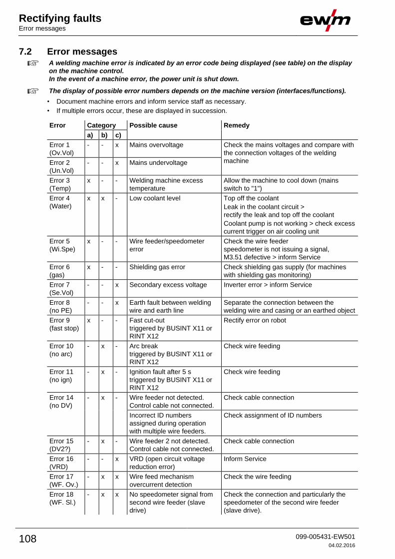
Rectifying faults Error messages
108 099-005431-EW501
04.02.2016
7.2 Error messages
A welding machine error is indicated by an error code being displayed (see table) on the display
on the machine control.
In the event of a machine error, the power unit is shut down.
The display of possible error numbers depends on the machine version (interfaces/functions).
• Document machine errors and inform service staff as necessary.
• If multiple errors occur, these are displayed in succession.
Error Category Possible cause Remedy
a) b) c)
Error 1
(Ov.Vol)
- - x Mains overvoltage Check the mains voltages and compare with
the connection voltages of the welding
machine Error 2
(Un.Vol)
- - x Mains undervoltage
Error 3
(Temp)
x - - Welding machine excess
temperature
Allow the machine to cool down (mains
switch to "1")
Error 4
(Water)
x x - Low coolant level Top off the coolant
Leak in the coolant circuit >
rectify the leak and top off the coolant
Coolant pump is not working > check excess
current trigger on air cooling unit
Error 5
(Wi.Spe)
x - - Wire feeder/speedometer
error
Check the wire feeder
speedometer is not issuing a signal,
M3.51 defective > inform Service
Error 6
(gas)
x - - Shielding gas error Check shielding gas supply (for machines
with shielding gas monitoring)
Error 7
(Se.Vol)
- - x Secondary excess voltage Inverter error > inform Service
Error 8
(no PE)
- - x Earth fault between welding
wire and earth line
Separate the connection between the
welding wire and casing or an earthed object
Error 9
(fast stop)
x - - Fast cut-out
triggered by BUSINT X11 or
RINT X12
Rectify error on robot
Error 10
(no arc)
- x - Arc break
triggered by BUSINT X11 or
RINT X12
Check wire feeding
Error 11
(no ign)
- x - Ignition fault after 5 s
triggered by BUSINT X11 or
RINT X12
Check wire feeding
Error 14
(no DV)
- x - Wire feeder not detected.
Control cable not connected.
Check cable connection
Incorrect ID numbers
assigned during operation
with multiple wire feeders.
Check assignment of ID numbers
Error 15
(DV2?)
- x - Wire feeder 2 not detected.
Control cable not connected.
Check cable connection
Error 16
(VRD)
- - x VRD (open circuit voltage
reduction error)
Inform Service
Error 17
(WF. Ov.)
- x x Wire feed mechanism
overcurrent detection
Check the wire feeding
Error 18
(WF. Sl.)
- x x No speedometer signal from
second wire feeder (slave
drive)
Check the connection and particularly the
speedometer of the second wire feeder
(slave drive).

Rectifying faults Error messages
099-005431-EW501
04.02.2016 109
Error Category Possible cause Remedy
a) b) c)
Error 56
(no Pha)
- - x Mains phase failure Check mains voltages
Error 59
(Unit?)
- - x Machine incompatible Check machine used
Legend for categories (error reset)
a) The error message will disappear once the error has been rectified.
b) The error message can be reset by pressing a key button:
Welding machine control Key button
RC1 / RC2
Expert
CarExpert / Progress (M3.11)
alpha Q / Concept / Basic / Basic S / Synergic /
Synergic S / Progress (M3.71) / Picomig 305
not possible
c) The error message can only be reset by switching the machine off and on again.
The shielding gas error (Err 6) can be reset by pressing the "Welding parameters" key button.

Rectifying faults Resetting JOBs (welding tasks) to the factory settings
110 099-005431-EW501
04.02.2016
7.3 Resetting JOBs (welding tasks) to the factory settings
All customised welding parameters that are stored will be replaced by the factory settings.
7.3.1 Resetting a single JOB
EXIT
RESETENTER
3 s
3 s 3 s
Figure 7-1
Display Setting/selection
RESET to factory settings
The RESET will be done after pressing the button.
The menu will be ended when no changes are done after 3 sec.
JOB-number (example)
The shown JOB will be set to ex works.
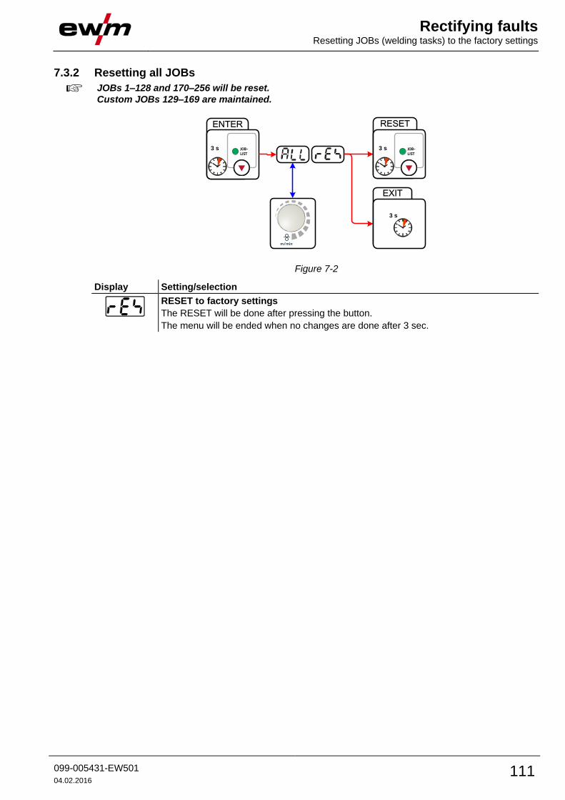
Rectifying faults Resetting JOBs (welding tasks) to the factory settings
099-005431-EW501
04.02.2016 111
7.3.2 Resetting all JOBs
JOBs 1–128 and 170–256 will be reset.
Custom JOBs 129–169 are maintained.
ENTER
3 s
EXIT
RESET
3 s
3 s
Figure 7-2
Display Setting/selection
RESET to factory settings
The RESET will be done after pressing the button.
The menu will be ended when no changes are done after 3 sec.

Rectifying faults Vent coolant circuit
112 099-005431-EW501
04.02.2016
7.4 Vent coolant circuit
Coolant tank and quick connect coupling of coolant supply and return are only fitted in machines
with water cooling.
To vent the cooling system always use the blue coolant connection, which is located as deep as
possible inside the system (close to the coolant tank)!
Figure 7-3
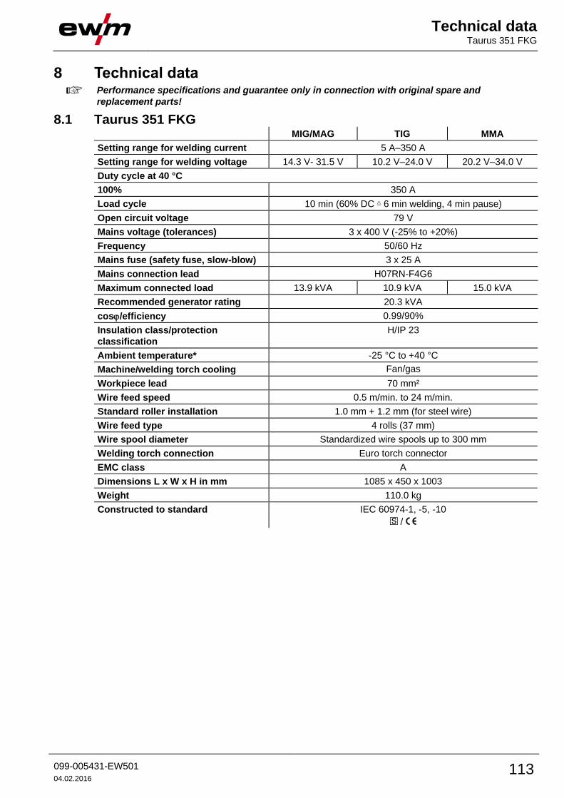
Technical data Taurus 351 FKG
099-005431-EW501
04.02.2016 113
8 Technical data Performance specifications and guarantee only in connection with original spare and
replacement parts!
8.1 Taurus 351 FKG MIG/MAG TIG MMA
Setting range for welding current 5 A–350 A
Setting range for welding voltage 14.3 V- 31.5 V 10.2 V–24.0 V 20.2 V–34.0 V
Duty cycle at 40 °C
100% 350 A
Load cycle 10 min (60% DC 6 min welding, 4 min pause)
Open circuit voltage 79 V
Mains voltage (tolerances) 3 x 400 V (-25% to +20%)
Frequency 50/60 Hz
Mains fuse (safety fuse, slow-blow) 3 x 25 A
Mains connection lead H07RN-F4G6
Maximum connected load 13.9 kVA 10.9 kVA 15.0 kVA
Recommended generator rating 20.3 kVA
cos/efficiency 0.99/90%
Insulation class/protection
classification
H/IP 23
Ambient temperature* -25 °C to +40 °C
Machine/welding torch cooling Fan/gas
Workpiece lead 70 mm²
Wire feed speed 0.5 m/min. to 24 m/min.
Standard roller installation 1.0 mm + 1.2 mm (for steel wire)
Wire feed type 4 rolls (37 mm)
Wire spool diameter Standardized wire spools up to 300 mm
Welding torch connection Euro torch connector
EMC class A
Dimensions L x W x H in mm 1085 x 450 x 1003
Weight 110.0 kg
Constructed to standard IEC 60974-1, -5, -10
/
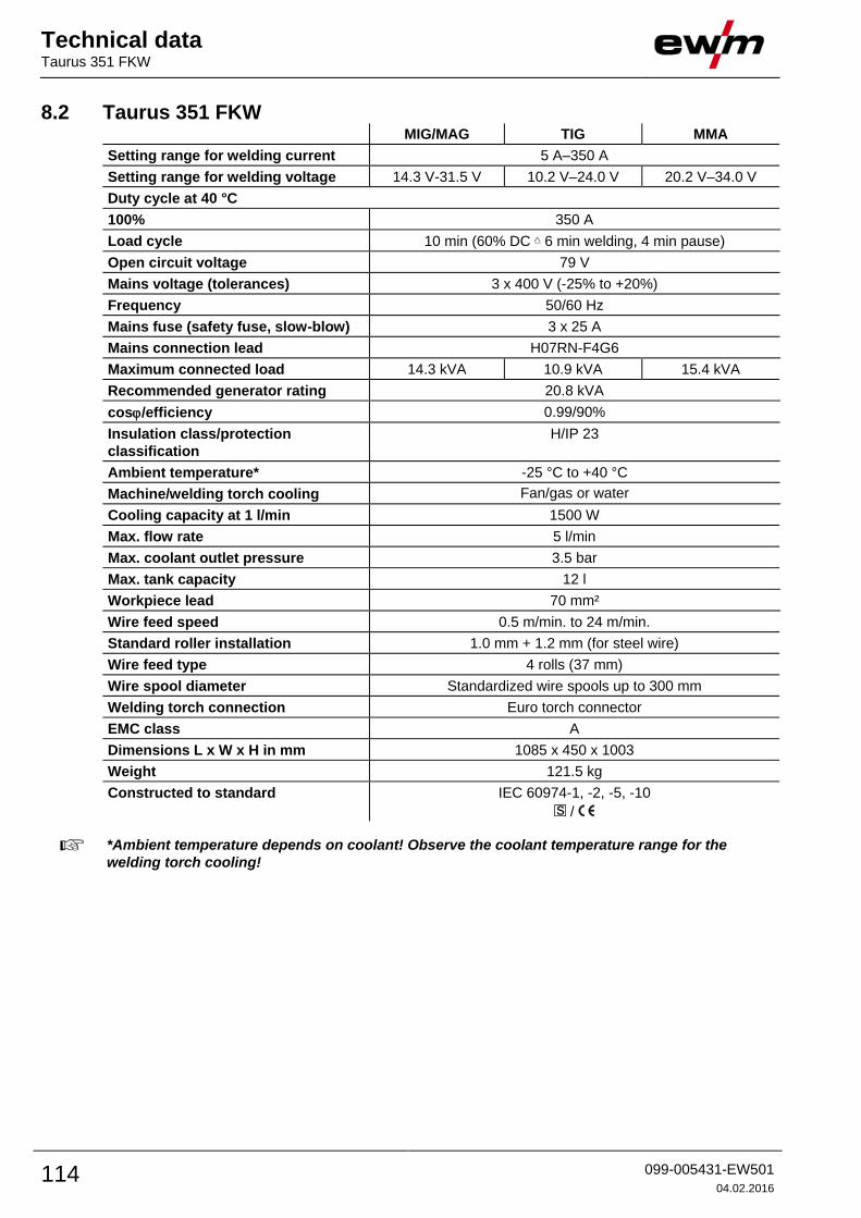
Technical data Taurus 351 FKW
114 099-005431-EW501
04.02.2016
8.2 Taurus 351 FKW MIG/MAG TIG MMA
Setting range for welding current 5 A–350 A
Setting range for welding voltage 14.3 V-31.5 V 10.2 V–24.0 V 20.2 V–34.0 V
Duty cycle at 40 °C
100% 350 A
Load cycle 10 min (60% DC 6 min welding, 4 min pause)
Open circuit voltage 79 V
Mains voltage (tolerances) 3 x 400 V (-25% to +20%)
Frequency 50/60 Hz
Mains fuse (safety fuse, slow-blow) 3 x 25 A
Mains connection lead H07RN-F4G6
Maximum connected load 14.3 kVA 10.9 kVA 15.4 kVA
Recommended generator rating 20.8 kVA
cos/efficiency 0.99/90%
Insulation class/protection
classification
H/IP 23
Ambient temperature* -25 °C to +40 °C
Machine/welding torch cooling Fan/gas or water
Cooling capacity at 1 l/min 1500 W
Max. flow rate 5 l/min
Max. coolant outlet pressure 3.5 bar
Max. tank capacity 12 l
Workpiece lead 70 mm²
Wire feed speed 0.5 m/min. to 24 m/min.
Standard roller installation 1.0 mm + 1.2 mm (for steel wire)
Wire feed type 4 rolls (37 mm)
Wire spool diameter Standardized wire spools up to 300 mm
Welding torch connection Euro torch connector
EMC class A
Dimensions L x W x H in mm 1085 x 450 x 1003
Weight 121.5 kg
Constructed to standard IEC 60974-1, -2, -5, -10
/
*Ambient temperature depends on coolant! Observe the coolant temperature range for the
welding torch cooling!

Technical data Taurus 401 FKG
099-005431-EW501
04.02.2016 115
8.3 Taurus 401 FKG MIG/MAG TIG MMA
Setting range for welding current 5 A–400 A
Setting range for welding voltage 14.3 V–34.0 V 10.2 V–26.0 V 20.2 V–36.0 V
Duty cycle at 40 °C
100% 400 A
Load cycle 10 min (60% DC 6 min welding, 4 min pause)
Open circuit voltage 79 V
Mains voltage (tolerances) 3 x 400 V (-25% to +20%)
Frequency 50/60 Hz
Mains fuse (safety fuse, slow-blow) 3 x 32 A
Mains connection lead H07RN-F4G6
Maximum connected load 17.2 kVA 13.2 kVA 18.2 kVA
Recommended generator rating 24.6 kVA
cos/efficiency 0.99/90%
Insulation class/protection
classification
H/IP 23
Ambient temperature* -25 °C to +40 °C
Machine/welding torch cooling Fan/gas
Workpiece lead 70 mm²
Wire feed speed 0.5 m/min. to 24 m/min.
Standard roller installation 1.0 mm + 1.2 mm (for steel wire)
Drive type 4 rolls (37 mm)
Wire spool diameter Standardized wire spools up to 300 mm
Welding torch connection Euro torch connector
EMC class A
Dimensions L x W x H in mm 1085 x 450 x 1003
Weight 110.0 kg
Constructed to standard IEC 60974-1, -5, -10
/

Technical data Taurus 401 FKW
116 099-005431-EW501
04.02.2016
8.4 Taurus 401 FKW MIG/MAG TIG MMA
Setting range for welding current 5 A–400 A
Setting range for welding voltage 14.3 V–34.0 V 10.2 V–26.0 V 20.2 V–36.0 V
Duty cycle at 40 °C
100% 400 A
Load cycle 10 min (60% DC 6 min welding, 4 min pause)
Open circuit voltage 79 V
Mains voltage (tolerances) 3 x 400 V (-25% to +20%)
Frequency 50/60 Hz
Mains fuse (safety fuse, slow-blow) 3 x 32 A
Mains connection lead H07RN-F4G6
Maximum connected load 17.5 kVA 13.5 kVA 18.5 kVA
Recommended generator rating 25.0 kVA
cos/efficiency 0.99/90 %
Insulation class/protection
classification
H/IP 23
Ambient temperature* -25 °C to +40 °C
Machine/welding torch cooling Fan/gas or water
Cooling capacity at 1 l/min 1500 W
Max. flow rate 5 l/min
Max. coolant outlet pressure 3.5 bar
Max. tank capacity 12 l
Workpiece lead 70 mm²
Wire feed speed 0.5 m/min. to 25 m/min.
Standard roller installation 1.0 mm + 1.2 mm (for steel wire)
Wire feed type 4 rolls (37 mm)
Wire spool diameter Standardized wire spools up to 300 mm
Welding torch connection Euro torch connector
EMC class A
Dimensions L x W x H in mm 1085 x 450 x 1003
Weight 121.5 kg
Constructed to standard IEC 60974-1, -2, -5, -10
/
*Ambient temperature depends on coolant! Observe the coolant temperature range for the
welding torch cooling!

Technical data Taurus 501 FKW
099-005431-EW501
04.02.2016 117
8.5 Taurus 501 FKW MIG/MAG TIG MMA
Setting range for welding current 5 A–500 A
Setting range for welding voltage 14.3 V–39.0 V 10.2 V–30.0 V 20.2 V–40.0 V
Duty cycle at 40 °C
60% 500 A
100% 430 A
Load cycle 10 min (60% DC 6 min welding, 4 min pause)
Open circuit voltage 79 V
Mains voltage (tolerances) 3 x 400 V (-25% to +20%)
Frequency 50/60 Hz
Mains fuse (safety fuse, slow-blow) 3 x 32 A
Mains connection lead H07RN-F4G6
Maximum connected load 24.9 kVA 19.3 kVA 25.6 kVA
Recommended generator rating 34.6 kVA
cos/efficiency 0.99/90%
Insulation class/protection
classification
H/IP 23
Ambient temperature* -25 °C to +40 °C
Machine/welding torch cooling Fan/gas or water
Cooling capacity at 1 l/min 1500 W
Max. flow rate 5 l/min
Max. coolant outlet pressure 3.5 bar
Max. tank capacity 12 l
Workpiece lead 95 mm²
Wire feed speed 0.5 m/min. to 25 m/min.
Standard roller installation 1.0 mm + 1.2 mm (for steel wire)
Wire feed type 4 rolls (37 mm)
Wire spool diameter Standardized wire spools up to 300 mm
Welding torch connection Euro torch connector
EMC class A
Dimensions L x W x H in mm 1085 x 450 x 1003
Weight 124.5 kg
Constructed to standard IEC 60974-1, -2, -5, -10
/
*Ambient temperature depends on coolant! Observe the coolant temperature range for the
welding torch cooling!
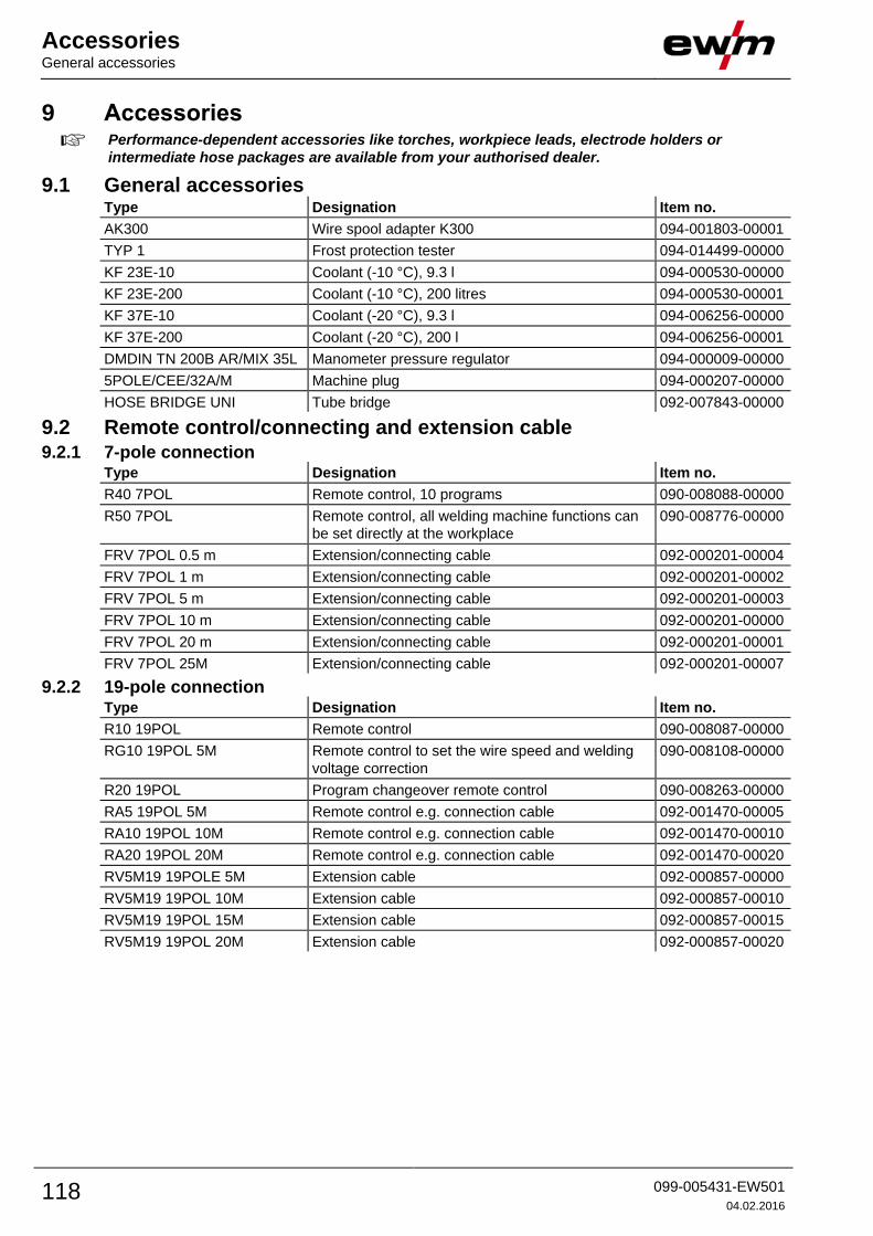
Accessories General accessories
118 099-005431-EW501
04.02.2016
9 Accessories Performance-dependent accessories like torches, workpiece leads, electrode holders or
intermediate hose packages are available from your authorised dealer.
9.1 General accessories Type Designation Item no.
AK300 Wire spool adapter K300 094-001803-00001
TYP 1 Frost protection tester 094-014499-00000
KF 23E-10 Coolant (-10 °C), 9.3 l 094-000530-00000
KF 23E-200 Coolant (-10 °C), 200 litres 094-000530-00001
KF 37E-10 Coolant (-20 °C), 9.3 l 094-006256-00000
KF 37E-200 Coolant (-20 °C), 200 l 094-006256-00001
DMDIN TN 200B AR/MIX 35L Manometer pressure regulator 094-000009-00000
5POLE/CEE/32A/M Machine plug 094-000207-00000
HOSE BRIDGE UNI Tube bridge 092-007843-00000
9.2 Remote control/connecting and extension cable 9.2.1 7-pole connection
Type Designation Item no.
R40 7POL Remote control, 10 programs 090-008088-00000
R50 7POL Remote control, all welding machine functions can
be set directly at the workplace
090-008776-00000
FRV 7POL 0.5 m Extension/connecting cable 092-000201-00004
FRV 7POL 1 m Extension/connecting cable 092-000201-00002
FRV 7POL 5 m Extension/connecting cable 092-000201-00003
FRV 7POL 10 m Extension/connecting cable 092-000201-00000
FRV 7POL 20 m Extension/connecting cable 092-000201-00001
FRV 7POL 25M Extension/connecting cable 092-000201-00007
9.2.2 19-pole connection Type Designation Item no.
R10 19POL Remote control 090-008087-00000
RG10 19POL 5M Remote control to set the wire speed and welding
voltage correction
090-008108-00000
R20 19POL Program changeover remote control 090-008263-00000
RA5 19POL 5M Remote control e.g. connection cable 092-001470-00005
RA10 19POL 10M Remote control e.g. connection cable 092-001470-00010
RA20 19POL 20M Remote control e.g. connection cable 092-001470-00020
RV5M19 19POLE 5M Extension cable 092-000857-00000
RV5M19 19POL 10M Extension cable 092-000857-00010
RV5M19 19POL 15M Extension cable 092-000857-00015
RV5M19 19POL 20M Extension cable 092-000857-00020

Accessories Options
099-005431-EW501
04.02.2016 119
9.3 Options Type Designation Item no.
ON LB Wheels 160x40MM Retrofit option for locking brake for machine wheels 092-002110-00000
ON Holder Gas Bottle <50L Holding plate for gas cylinders smaller than 50 litres 092-002151-00000
ON Shock Protect Ram protection retrofit option 092-002154-00000
ON HS XX1 Mount for hose packages and remote control 092-002910-00000
ON Filter T/P Retrofit option contamination filter for air inlet 092-002092-00000
ON Tool Box Retrofit option tool box 092-002138-00000
9.4 Computer communication Type Designation Item no.
PC300.Net PC300.Net welding parameter software kit incl.
cable and SECINT X10 USB interface
090-008777-00000
FRV 7POL 5 m Extension/connecting cable 092-000201-00003
FRV 7POL 10 m Extension/connecting cable 092-000201-00000
FRV 7POL 20 m Extension/connecting cable 092-000201-00001
QDOC9000 V2.0 Set consisting of interface, documentation software,
connection lead
090-008713-00000
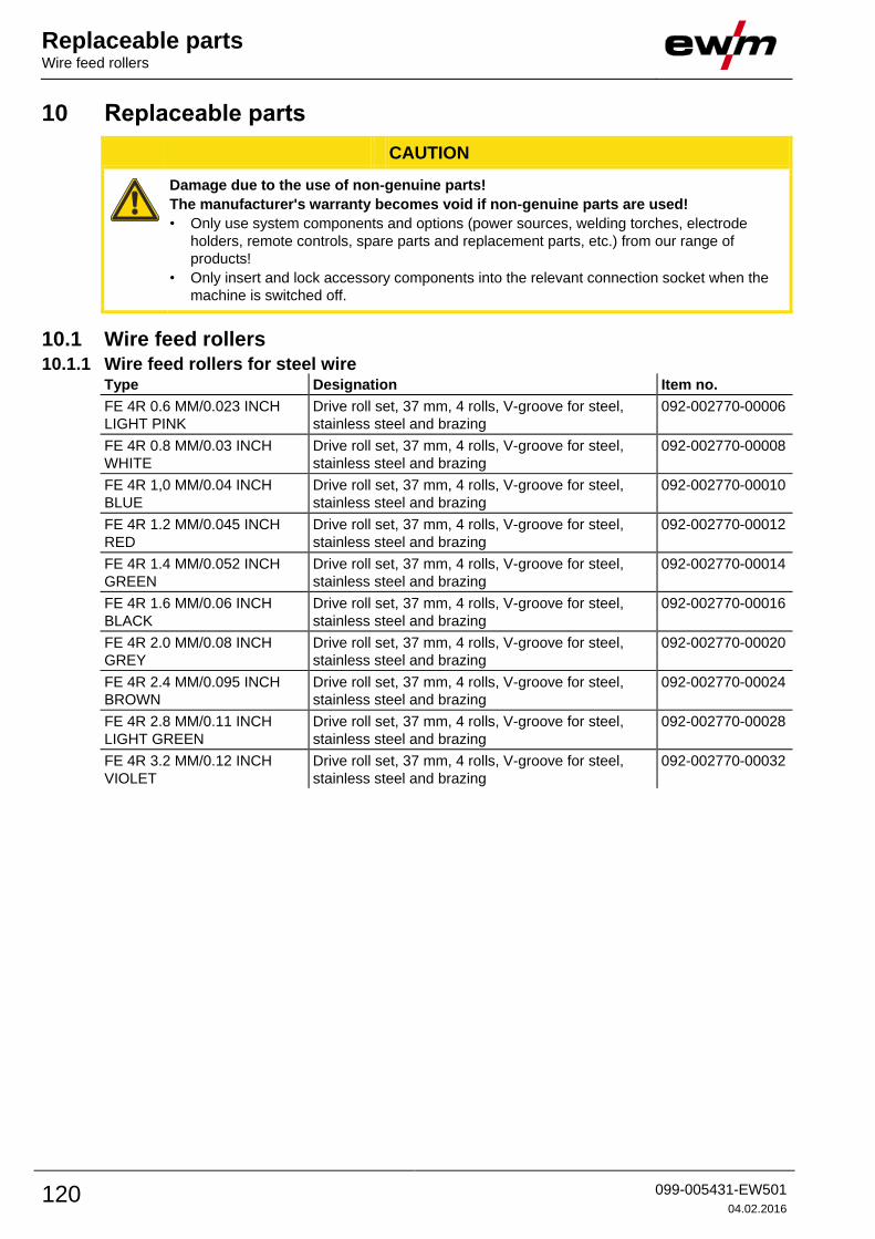
Replaceable parts Wire feed rollers
120 099-005431-EW501
04.02.2016
10 Replaceable parts
CAUTION
Damage due to the use of non-genuine parts!
The manufacturer's warranty becomes void if non-genuine parts are used!
• Only use system components and options (power sources, welding torches, electrode
holders, remote controls, spare parts and replacement parts, etc.) from our range of
products!
• Only insert and lock accessory components into the relevant connection socket when the
machine is switched off.
10.1 Wire feed rollers 10.1.1 Wire feed rollers for steel wire
Type Designation Item no.
FE 4R 0.6 MM/0.023 INCH
LIGHT PINK
Drive roll set, 37 mm, 4 rolls, V-groove for steel,
stainless steel and brazing
092-002770-00006
FE 4R 0.8 MM/0.03 INCH
WHITE
Drive roll set, 37 mm, 4 rolls, V-groove for steel,
stainless steel and brazing
092-002770-00008
FE 4R 1,0 MM/0.04 INCH
BLUE
Drive roll set, 37 mm, 4 rolls, V-groove for steel,
stainless steel and brazing
092-002770-00010
FE 4R 1.2 MM/0.045 INCH
RED
Drive roll set, 37 mm, 4 rolls, V-groove for steel,
stainless steel and brazing
092-002770-00012
FE 4R 1.4 MM/0.052 INCH
GREEN
Drive roll set, 37 mm, 4 rolls, V-groove for steel,
stainless steel and brazing
092-002770-00014
FE 4R 1.6 MM/0.06 INCH
BLACK
Drive roll set, 37 mm, 4 rolls, V-groove for steel,
stainless steel and brazing
092-002770-00016
FE 4R 2.0 MM/0.08 INCH
GREY
Drive roll set, 37 mm, 4 rolls, V-groove for steel,
stainless steel and brazing
092-002770-00020
FE 4R 2.4 MM/0.095 INCH
BROWN
Drive roll set, 37 mm, 4 rolls, V-groove for steel,
stainless steel and brazing
092-002770-00024
FE 4R 2.8 MM/0.11 INCH
LIGHT GREEN
Drive roll set, 37 mm, 4 rolls, V-groove for steel,
stainless steel and brazing
092-002770-00028
FE 4R 3.2 MM/0.12 INCH
VIOLET
Drive roll set, 37 mm, 4 rolls, V-groove for steel,
stainless steel and brazing
092-002770-00032
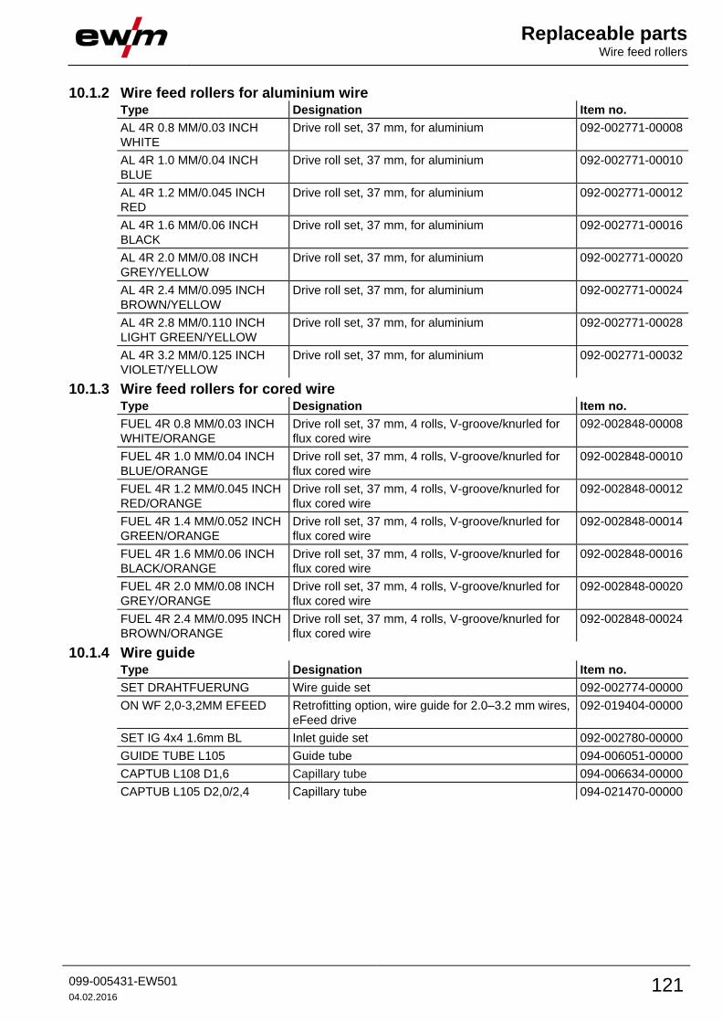
Replaceable parts Wire feed rollers
099-005431-EW501
04.02.2016 121
10.1.2 Wire feed rollers for aluminium wire Type Designation Item no.
AL 4R 0.8 MM/0.03 INCH
WHITE
Drive roll set, 37 mm, for aluminium 092-002771-00008
AL 4R 1.0 MM/0.04 INCH
BLUE
Drive roll set, 37 mm, for aluminium 092-002771-00010
AL 4R 1.2 MM/0.045 INCH
RED
Drive roll set, 37 mm, for aluminium 092-002771-00012
AL 4R 1.6 MM/0.06 INCH
BLACK
Drive roll set, 37 mm, for aluminium 092-002771-00016
AL 4R 2.0 MM/0.08 INCH
GREY/YELLOW
Drive roll set, 37 mm, for aluminium 092-002771-00020
AL 4R 2.4 MM/0.095 INCH
BROWN/YELLOW
Drive roll set, 37 mm, for aluminium 092-002771-00024
AL 4R 2.8 MM/0.110 INCH
LIGHT GREEN/YELLOW
Drive roll set, 37 mm, for aluminium 092-002771-00028
AL 4R 3.2 MM/0.125 INCH
VIOLET/YELLOW
Drive roll set, 37 mm, for aluminium 092-002771-00032
10.1.3 Wire feed rollers for cored wire Type Designation Item no.
FUEL 4R 0.8 MM/0.03 INCH
WHITE/ORANGE
Drive roll set, 37 mm, 4 rolls, V-groove/knurled for
flux cored wire
092-002848-00008
FUEL 4R 1.0 MM/0.04 INCH
BLUE/ORANGE
Drive roll set, 37 mm, 4 rolls, V-groove/knurled for
flux cored wire
092-002848-00010
FUEL 4R 1.2 MM/0.045 INCH
RED/ORANGE
Drive roll set, 37 mm, 4 rolls, V-groove/knurled for
flux cored wire
092-002848-00012
FUEL 4R 1.4 MM/0.052 INCH
GREEN/ORANGE
Drive roll set, 37 mm, 4 rolls, V-groove/knurled for
flux cored wire
092-002848-00014
FUEL 4R 1.6 MM/0.06 INCH
BLACK/ORANGE
Drive roll set, 37 mm, 4 rolls, V-groove/knurled for
flux cored wire
092-002848-00016
FUEL 4R 2.0 MM/0.08 INCH
GREY/ORANGE
Drive roll set, 37 mm, 4 rolls, V-groove/knurled for
flux cored wire
092-002848-00020
FUEL 4R 2.4 MM/0.095 INCH
BROWN/ORANGE
Drive roll set, 37 mm, 4 rolls, V-groove/knurled for
flux cored wire
092-002848-00024
10.1.4 Wire guide Type Designation Item no.
SET DRAHTFUERUNG Wire guide set 092-002774-00000
ON WF 2,0-3,2MM EFEED Retrofitting option, wire guide for 2.0–3.2 mm wires,
eFeed drive
092-019404-00000
SET IG 4x4 1.6mm BL Inlet guide set 092-002780-00000
GUIDE TUBE L105 Guide tube 094-006051-00000
CAPTUB L108 D1,6 Capillary tube 094-006634-00000
CAPTUB L105 D2,0/2,4 Capillary tube 094-021470-00000
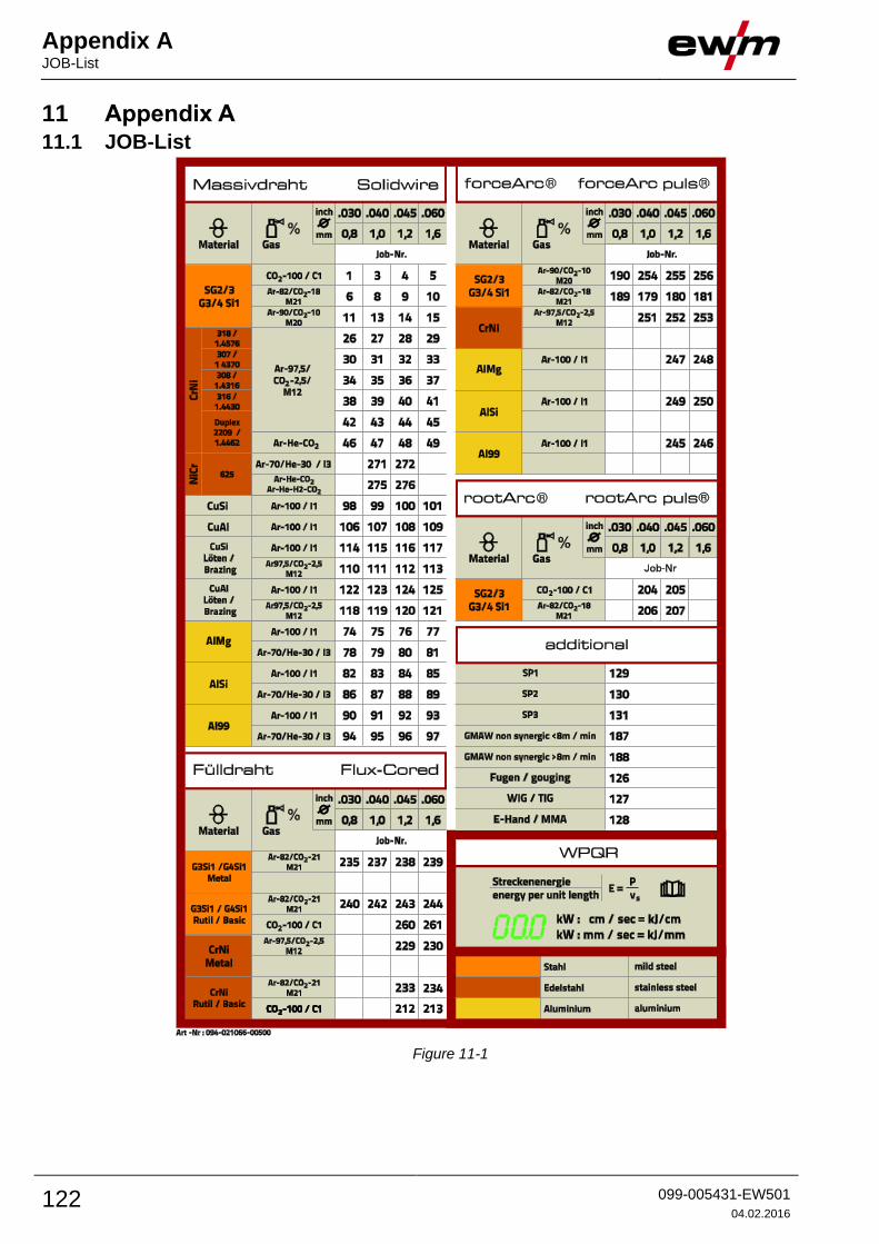
Appendix A JOB-List
122 099-005431-EW501
04.02.2016
11 Appendix A 11.1 JOB-List
Figure 11-1
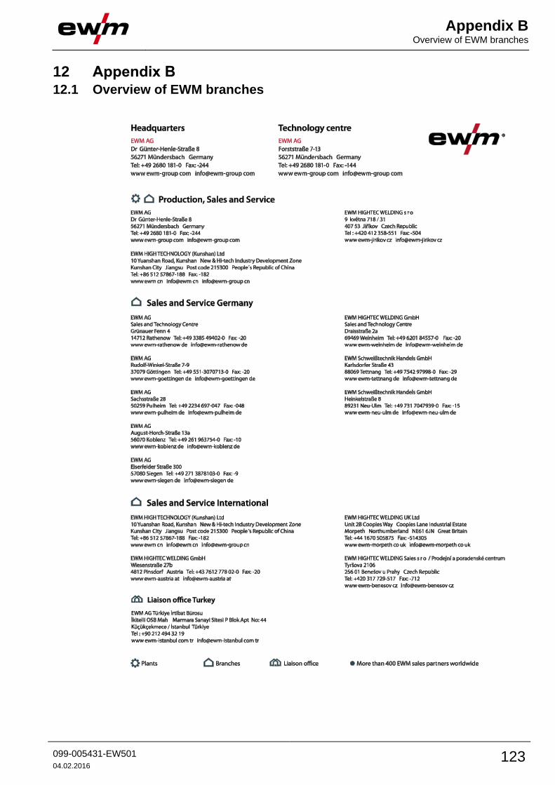
Appendix B Overview of EWM branches
099-005431-EW501
04.02.2016 123
12 Appendix B 12.1 Overview of EWM branches