TATA INSTITUTE OF FUNDAMENTAL RESEARCH portal.pdf · TATA INSTITUTE OF FUNDAMENTAL RESEARCH Homi...
58
Page 1 of 4 TATA INSTITUTE OF FUNDAMENTAL RESEARCH Homi Bhabha Road, Colaba, Mumbai – 400 005. A Deemed University Telephone : +91-22-2278 2890/2886/2887/2888 Email : [email protected] Purchase Fax : +91-22-2280 4566 : [email protected] Website : www.tifr.res.in : [email protected] PUBLIC TENDER NO. : TFR/PD/IC13-175/PUB PUBLISHED ON : 18.10.2013 DUE DATE : 25.11.2013 TENDER FEE : Rs. 500/- COST OF TENDER : Approx. Rs. 18 Crore TYPE OF TENDER : TWO PART ------------------------------------------------------------------------------------ DESCRIPTION OF MATERIAL Near Infrared Spectrometer For Use With ARIES 3.6 Meter Telescope as per the specifications in the attached sheet For any queries please contact [email protected], [email protected], [email protected] ------------------------------------------------------------------------------------- Closing time and date : 13.00 Hours on 25.11.2013 Tender will be open at : 14.00 Hours on 25.11.2013 Both Technical Bid (Part A) and Commercial Bid (Part B) to be submitted within the due date and time in separate envelopes and marked on top as Part A and Part B. These two sealed envelopes should be further put in one Master Envelope superscribed with the Tender No., Due Date in Bold Letters. Please see attached sheet for conditions of tender. Shekhar G.K. Administrative Officer ‘C’
Transcript of TATA INSTITUTE OF FUNDAMENTAL RESEARCH portal.pdf · TATA INSTITUTE OF FUNDAMENTAL RESEARCH Homi...
Page 1 of 4
TATA INSTITUTE OF FUNDAMENTAL RESEARCH Homi Bhabha Road, Colaba, Mumbai – 400 005.
A Deemed University Telephone : +91-22-2278 2890/2886/2887/2888 Email : [email protected] Purchase Fax : +91-22-2280 4566 : [email protected] Website : www.tifr.res.in : [email protected]
PUBLIC TENDER NO. : TFR/PD/IC13-175/PUB
PUBLISHED ON : 18.10.2013
DUE DATE : 25.11.2013
TENDER FEE : Rs. 500/- COST OF TENDER : Approx. Rs. 18 Crore
TYPE OF TENDER : TWO PART
------------------------------------------------------------------------------------
DESCRIPTION OF MATERIAL
Near Infrared Spectrometer For Use With ARIES 3.6 Meter
Telescope as per the specifications in the attached sheet
For any queries please contact [email protected], [email protected],
-------------------------------------------------------------------------------------
Closing time and date : 13.00 Hours on 25.11.2013
Tender will be open at : 14.00 Hours on 25.11.2013
Both Technical Bid (Part A) and Commercial Bid (Part B) to be submitted within the due date and time in separate envelopes and
marked on top as Part A and Part B. These two sealed envelopes should be further put in one Master Envelope superscribed with the Tender No.,
Due Date in Bold Letters.
Please see attached sheet for conditions of tender.
Shekhar G.K. Administrative Officer ‘C’

Page 2 of 4
TATA INSTITUTE OF FUNDAMENTAL RESEARCH (Deemed University)
National Centre of the Government of India for Nuclear Science and Mathematics HOMI BHABHA ROAD, COLABA, MUMBAI – 400 005
(PURCHASE SECTION)
Terms and Conditions
1. PART “A” (Technical Bid) consisting of Technical Bid & Commercial Terms and PART “B” (Commercial Bid) consisting of only Price shall be submitted
in separate sealed envelopes duly superscribed with the tender enquiry number,
and the due date in bold letters, addressed to the Purchase Officer, Tata Institute
of Fundamental Research, Homi Bhabha Road, Colaba, Mumbai – 400 005. The
envelopes should be clearly marked on top as either PART “A” or PART “B”.
The two sealed covers should be further put in a master cover superscribed with
the Tender Enquiry No., Due Date in bold letters, addressed to the Purchase
Officer, Tata Institute of Fundamental Research, Homi Bhabha Road, Colaba,
Mumbai – 400 005. The sealed master envelop has to be delivered by
hand/courier at the security Gate Officer of TIFR on or before 13.00 hrs on the
due date specified. The technical bid will be opened in the presence of attending
tenderers at 14.00 hrs on the due date at Purchase Section, TIFR Mumbai.
Tenders submitted after 13.00 hrs. on due date will not be considered.
2. In case the PART ‘A’ and Part ‘B’ bids are not sealed in separate envelopes the tender will be rejected.
3. The technical bid should not contain any indication of the price.
4. The price should be shown against each item in Commercial Bid.
5. After scrutiny of Technical Bids, Commercial bids of only those bidders who are
shortlisted on technical basis will be opened at on later date. The opening date,
time and venue will be intimated to the technically successful bidder.
6. Tender Forms can be obtained from the Purchase Section on payment of the
tender fees (non-refundable) of Rs.500/- by cash/Demand Draft in favour of, The
Registrar, Tata Institute of Fundamental Research, Mumbai along with a letter
address to the cashier, Accounts Department on any working day between 11.00
to 12.30 hrs. and 13.00 to 14.00 hrs.
7. The firm who wishes to download the specifications, terms and conditions may do
so. While submitting the quotation, a DD of Rs.500/- for each tender drawn in
favour of The Registrar, Tata Institute of Fundamental Research, Mumbai may
please be enclosed along with Technical Bid. In case of Foreign Suppliers
prepare advance cheque for US$100/-.

Page 3 of 4
TATA INSTITUTE OF FUNDAMENTAL RESEARCH
8. After downloading the documents please inform your company details such as
name, address, telephone nos., contact person and email address etc. by email to
us. ([email protected], [email protected], [email protected]) to enable us to
inform prospective bidder for any corrigendum/changes if any; in the Tender
document before due date.
9. Quotations must be valid for a period of 180 days from the due date.
10. Tenders containing correction, overwriting will not be considered. Late or
delayed/Unsolicited quotations/offers shall not be considered at all. These will be
returned to the firms as it is. Post tender revisions/corrections shall also not be
considered.
11. Tenderer should sign on all the pages of the technical bid and the price bid.
12. The offer for Import item should indicate separately the price on Ex-works basis
(duly packed airworthy / seaworthy and of international standard ). And also on
CIF, TIFR, Mumbai basis (i.e. inclusive of packing, air freight, handling,
insurance for the material up to TIFR, Colaba, Mumbai). TIFR will provide all
necessary documents required for customs clearance. For local item/supply, offer
should be the total landed cost for delivery at TIFR, Mumbai.
13. Tenders who do not comply with any of the condition are liable to be rejected.
14. The Institute shall be under no obligation to accept the lowest or any other tender
received in response to this tender notice and shall be entitled to reject any tender
without assigning any reason whatsoever.
15. TIFR reserves the right to place the order for part/reduced quantity than what is
specified in the tender.
16. For Import cases: No Agency commission will be paid as per Govt. of India rules.
17. We are exempted from payment of Excise Duty under notification number 10/97
dated 01.03.1997and Customs Duty under notification No.51/96 dated 23.07.1996
for all procurements/supply meant exclusively for scientific and research purposes.
Whenever the exemption certificate not honoured by the authorities, the
applicable excise duty will have to be paid. Hence Excise Duty and Customs Duty,
if any, should be shown separately. No other charges than those mentioned clearly
in the quotation will be paid.
Page 4 of 4
TATA INSTITUTE OF FUNDAMENTAL RESEARCH
18. SALES TAX: TIFR does not have any exemption/concession on payment of
Sales Tax/VAT and we are not authorized to issue any Sales Tax Form ‘C’ & ‘D’
19. The delivery period should be specifically stated in the quote.
20. COMMENCEMENT OF WARRANTY PERIOD: The warranty period of an
item shall commence from the date of receipt of the item in good working
condition and satisfactory installation/commissioning/demonstration (including
reproduction of all benchmarks) at the project site, whichever is later.
21. ANNUAL MAINTENANCE CHARGES: The party must mention in the
quotation, the rate/amount of annual maintenance charges, if we opt for
maintenance contract after expiry of the warranty period.
22. Specifications are basic essence of the product. It must be ensured that the offers
must be strictly as per our specifications. At the same time it must be kept in mind
that merely copying our specifications in the quotation shall not make the parties
eligible for consideration of the quotation. A quotation has to be supported with
the printed technical leaflet/literature of the quoted model of the item by the
quoting party/manufacturer.
23. OBSERVANCE OF LOCAL LAWS: Wherever applicable (particularly for
Local vendors), the vendor / contractor shall comply with all law, statutory rules
& regulations etc. The vendor/ contractor shall obtain all necessary permits /
approval from the local Governing Body, Police, and other concerned Authorities
as may be required under law. The vendor /contractor shall pay all types of taxes,
fees, license charges, deposits, duties, tolls, royalty or other charges that may be
leviable on account of any the operations connected with the execution of this
work/ contract.
24. In case of any interpretational issues arises in this tender, the
interpretation/decision of TIFR shall be final and binding on the bidder.
25. It is the responsibility of the vendor to make sure that the system being proposed
can be exported to India with TIFR as the end user. All clarificatory
documentation must be submitted with the Bid.
26. TIFR reserve the right to ask for or to provide any clarification, changes after the
release of this tender. Any changes or clarifications provided by TIFR may be checked at TIFR website www.tifr.res.in/tenders
ADMINISTRATIVE OFFICER
(PURCHASE SECTION)
TIFR, MUMBAI
Tender for TANSPEC (TIFR – ARIES NEAR INFRARED SPECTROMETER)
A Near Infrared Spectrometer (TANSPEC) is proposed to be built as a collaboration project between TIFR (Tata Institute of Fundamental Research, Mumbai, India) and ARIES (Aryabhatta Research Institute of Observational Sciences, Nainital, India) to be used on the main port of the 3.6 metre Devasthal Optical Telescope.
Technical Bids (Part A) and Commercial Bids (Part B) are invited from vendors, with qualifications mentioned below, to design, build and install TANSPEC with the specifications given below.
1) Instrument Overview:The TANSPEC should be designed for use with the 3.6 metre Devasthal Optical Telescope of ARIES with the average seeing of 1.0 arc seconds in the J Band. It should consist of the main spectrometer channel and an Infrared guide channel and should have an image scale of 0.33 arc-seconds / pixel for the spectrometer and the guide channel. The following documents have the details of the telescope.
a) 3.6m-specifications.pdf (Instrument interface requirements)
b) nNinane-spie2012-8444-102.pdf (SPIE Paper about the telescope)
c) nNinane-spie2012-8444-671.pdf (SPIE Paper about the telescope)
d) tel-072-2010-02_1985_0700_001_D-ICDrawing.pdf (Mechanical drawing of the allowed instrument area envelope)
e) 3.6m Telscope_Original design.SES (Zemax sessions file)
f) 3.6m Telscope_Original design.ZMX (Zemax raytrace file)
2) Target Science:TANSPEC will be extremely sensitive to low temperature stellar photospheres (T · 2500 K) and objects surrounded by warm dust envelopes or embedded in dust/molecular clouds. It is therefore particularly suited to the study of low and very low mass stellar populations (M/Ldwarfs, brown dwarfs), strong mass-losing stars on the asymptotic giant branch (AGB),
young stellar objects (YSOs) still in their proto-stellar envelopes and active galactic nuclei (AGN). A few of the important programs to be pursued with the proposed TANSPEC are described below:i) Low-mass stars (red and brown dwarfs):Since low-mass stars are cool (red M-dwarfs, typically 3000 K and brown dwarfs, 2500-500 K), the NIR is ideally suited to study their space density. K-band spectroscopy will be very useful to determine the nature of these sources.ii) Confirmation of metal poor subdwarfs:Low-mass subdwarfs are considered to be important tracers of Galactic structure and chemical enrichment history and are representatives of the first generations of star formation.
ojha
Text Box
TANSPEC_indent_v2.2_09102013.pdf

The relative band strengths of various molecular bands are crucial in determining the elemental abundances in these stars which in turn can provide useful insight into the chemical evolution history of our galaxy.iii) Evolved giant, Supergiant and Asymptotic Giant Branch stars:The IRAS, ISO, Spitzer and AKARI surveys have identified tens of thousands of such objects. These contain objects of quite different natures (e.g. O-rich stars and C-rich stars). It is likely that the combination of NIR data with IRAS, ISO and Spitzer surveys will give us systematic, statistically complete information on the various phenomena occurring during this mass loss phase. The CaI triplet and the NaI line together with the CO absorption at 2.3 μm are excellent metallicity indicators. A systematic survey of K/M giants, to derive the metallicities and especially the metallicity gradient in our Galaxy, is important to study the formation and evolution of our Galaxy. The atmospheres of AGB stars are strongly affected by time-dependent highly dynamical phenomena. They show large spectral variation as a function of their period. The simultaneous study of optical and NIR spectra is important to constrain the dynamical models of AGB stars. A large monitoring program of AGB stars would be essential to confront them with the latest hydrodynamic models.iv) Galactic Structure:At the wavelength of visual light our view of the inner parts of the Galaxy is blocked by interstellar extinction, but at infrared wavelengths the blockage is much reduced. Our Galaxy contains large number of red giant stars. It is possible to detect all red giants without circumstellar envelopes out to halfway through the Galaxy, roughly within the distance of the galactic centre in near-IR wavelength range thus allowing us to study the hidden inner parts of the Galaxy. Spiral arms are also well defined by dust clouds. Wolf diagrams can be used on a long period in order to determine their distances. Use of a spectral band relatively unaffected by interstellar extinction in conjunction with optical surveys will improve the determination of distances. Finally, the relative numbers of C-rich and O-rich stars as a function of galactocentric distance and the number of mass losing metal poor AGB stars can be estimated with photometric methods. This will provide important information for the question of metal enrichment of the Galactic disk by low and intermediate mass stars during the history of the Galaxy.v) Star Formation:One of the major impacts of the NIR instrument will be to probe giant molecular clouds and large dark clouds in search of low luminosity protostars, in order to derive the initial mass function (IMF) and the star forming efficiency (SFE). The NIR range is very sensitive to
protostars because of their high luminosity in this range, the low extinction of the surrounding interstellar dust (1/10 of AV in K-band), and the absence of thermal noise that hampers high-sensitivity, mid-infrared surveys, at least from the ground. NIR spectra are a powerful tool to classify and identify embedded YSOs and thus to constrain the star formation rate in our Galaxy. vi) PMS stars in very young star clusters:The presence of dust and gas within young star clusters and in their immediate vicinity is well established. A medium resolution spectroscopy with 3.6-meter telescope of these objects will help (i) determine accurate masses in binary, (ii) establish the nature of circumstellar environment and the evolutionary link from newborn stars to the main sequence stages.
vii) Spectroscopic study of T Tauri stars:Classical T Tauri stars (CTTS) are characterised by strong H emission lines. It is believed that these emission lines arise from gas being accreted onto the stellar surface through the inner regions of a circumstellar disk along the stellar magnetic field lines. Some of the H emission lines can be used to estimate the accretion rates and luminosities as well. For better modelling, simultaneous observations are essential due to the notorious variability of the spectra of CTTSs. viii) Embedded clusters in molecular cloud:The discovery of a large number of embedded clusters in molecular clouds over the last two decades has led to the realization that these young protoclusters are the birth places for a significant fraction of all star formation activity currently occurring in the Galaxy. Following are a few frontline problems: (i) The IMF towards the low mass stars (ii) Is the circumstellar disk lifetime the same in all clusters? (iii) How frequently do the O stars form in embedded clusters? (iv) Is the fraction of brown dwarfs always ~ 20 - 25% of a cluster population? Resolving these issues will require an extensive effort in both observations and theory. The proposed TANSPEC at the Cassegrain focus of the 3.6-meter telescope is a must to take a variety of challenging astrophysical problems as mentioned above.ix) Time-delay measurements in Gravitational Lenses:Hubble Constant is a fundamental parameter of the standard cosmology which specifies the natural scale length of the Universe as well as the unit for the density of matter in addition to a measure of the age of the Universe. Time-delay between signals appearing in the multiple images of well-constrained gravitational lens systems provides an alternative way to estimate the Hubble Constant. The intrinsic variability in a lensed object will not appear in the images simultaneously because of the unequal path-length traversed by the photons from the images to the observer as well as due to the differential gravitational potential at the lens seen by them. The time-delay is proportional to the square of the separation between the images and to the effective distance to the lens system apart from a geometrical factor depending upon the mass distribution within the lens. We propose extended monitor in the two NIR broad
bands, of only those lens systems in which observations provide sufficient constraints to determine the models reliably. Further, whenever a sharp variability is seen in one of the images, multi-wavelength observations at frequent time-intervals will be carried out to determine if the event is caused by microlens. A systematic observational programme based on gravitational lens will also provide a means to estimate the baryonic column density in the lens and number density of stellar mass objects. Thus it could be a powerful tool for the study of physical cosmology at the galactic scale without using a very large telescope except for follow-up observations.x) The Optical − Near Infrared Spectral Library:Traditional methods of stellar classifications are slow, tedious and arguably subjective. Intelligent systems based on pattern recognition tools like Artificial Neural Networks are now being used to classify stars. These techniques are essential where large data bases are produced in various survey projects. However, classification of stellar spectra using neural network is achieved by appropriately training the network first. During training, the network output and the desired outputs are compared and the network weights are adjusted. For the purpose of training the network, it is appropriate to have stellar libraries with wide spectral
coverage and moderate resolution. Currently available stellar libraries are either in optical region or in infrared region obtained using various telescopes and instruments in different resolutions. It is therefore, desired to have a spectral library produced using same telescope and instrument from optical to NIR wavelengths simultaneously to achieve a much more reliable spectral classification using artificial neural networks. The proposed instrument with its wide wavelength coverage and with medium resolution (R ~ 2000 - 3000) can be used to produce a spectral library of a large number of stars which can be used as training samples for the future automated stellar classification tools. Absolute flux calibration can be made using 2MASS. The Infrared Guide Channel can also provide photometry.
3) Wavelength range:Option (i): 0.5 microns to 2.5 micronsOption (ii): 0.8 microns to 2.5 micronsOption (iii): 1.0 micron to 2.5 microns
Any one of the above three options will be chosen depending on the feasibility, size, complexity and cost.
4) Spectral Resolution:This consists of two modes
1) Cross dispersed high resolution mode with resolving power of ~2000 – 3000 at the narrowest slit position
2) Low resolution mode with resolving power of ~100.
5) Slit Wheel:The slit wheel should have 12 positions with reflective slit mirrors being used to feed the guide channel.
a) 4 Nos. Short slits for the cross dispersed mode with length of 15 arc-seconds and widths of 0.99, 1.32, 1.65 and 1.98 arc-seconds.
b) 4 Nos. Long slits with length of 60 arc-seconds or more and widths of 0.99, 1.32, 1.65 and 1.98 arc-seconds
c) 1 No. mirror without slit for guide channel and also blank for the spectrometer channel
d) 3 Nos. blank positions for future upgrade / expansion.
6) Detectors:
a) For Spectrometer Channel:
Teledyne Science Grade H2RG Array (2048 x 2048 pixels)Image scale of 0.33 arc-seconds per pixelRead noise of 5 electrons with multiple samplingDark current of <= 1 electron / sec.Minimum integration time of 4 seconds

Maximum integration time of 600 seconds.Sampling: Up the Ramp, Double Correlated Sampling, Non Destructive Reads (NDRs) to provide 5 electrons read noise, Single Read, Sub-Arrays
b) For the Infrared Guide Channel:
Teledyne Engineering Grade A H2RG Array (2048 x 2048 pixels)Image scale of 0.33 arc-seconds per pixelMinimum field of view of 60 arc-secondsJ, H, Ks and 2 narrow band filters and 5 spare locations in the filter wheelRead noise of 12 electronsDark current of 3 electrons / sec.Sub-array capabilityMinimum Integration time of 0.1 seconds with sub-array readoutMinimum 10 frames per secondSoftware to guide on slit image and send corrections to Telescope Control System (TCS)Software to guide on field objects
7) Temperature Control:Optical bench and science and guide detectors to be maintained at 78 +/- 2 degress Kelvin and Science Grade detector temperature stability to be 1.0 milliKelvin. The temperature stability of the optical bench should be 10 milliKelvin.
Cooling to be achieved through hybrid system with closed cycle cooling for the radiation shields and liquid nitrogen cooling for the optical bench and detectors.
Alternatively, the cooling for the entire system could be through closed cycle coolers with the above requirements.
8) Calibration Units:i) Integrating Sphereii) Argon Discharge Lampiii) Optics for the calibration module should match the telescope feed f/no. and should uniformly fill the instrument pupil.iv) Continuum lamp for high resolution modev) Continuum lamp for low resolution modevi) Pickoff mirror and lamp control should be remotely operated from the instrument software.
9) Electronics:All instrument electronics should be mounted with the instrument at CASS and consists of the array controllers for the two detectors, preamps, A/D boards, digital signal processing boards, remote Ethernet power control of all elements, mechanism drivers, temperature control, monitoring of all parameters, Ethernet switch, power supplies, etc., to be controlled by a main Unix Workstation placed in the control room.
Electronics cabinets to be insulated and must be designed for glycol cooling to ambient temperature using glycol chillers which are not a part of the scope of this instrument.
Alternatively, a Teledyne SIDECAR based system can be used with a cryogenic SIDECAR for both detectors.
10) Mechanical:i) Mechanisms for Slit wheel, Guide Channel Filter Wheel, Grating Wheel, Spectrometer Channel Detector Focus and Calibration Unit Pick-off mirrorii) Mounting Plateiii) Back focus from telescope mounting plate specified in the telescope documents.iv) Instrument envelope as specified in the telescope documents.v) Instrument weight and Centre of Gravity specified in the telescope documents.
11) Software:Should be able to interface to the Telescope Control System specified in the telescope documentsGuide Channel SoftwareScience Data Channel SoftwareTemperature Control Software for the optical bench and the detectors.Mechanism Control SoftwarePower On/Off Control SoftwareScripting and MacrosData Handling SoftwareQuick-look data viewerRemote operation over VNCTwo NIC’s for instrument subnet and the external subnet
12) Documentation:User’s ManualCryostat Assembly and Maintenance ManualSoftware Maintenance Manual including all source codesDetailed mechanical drawings as builtDetailed electrical cabling diagrams and schematicsZemax raytrace files as built and optical performance documentCold filter transmission versus wavelength graphsVendor site test report
13) Other requirements:The vendor will be expected to obtain Export license for all “International Traffic in Arms Regulations (ITAR)” items and a Technical Assistance Agreement (TAA) for all ITAR items will have to be signed with TIFR and ARIES. This will also include members of the Review committees which will be specified at the time of signing of the contract.

14) Contract:A Contract for the entire project will have to be signed by the vendor with TIFR and ARIES. A sample contract document is attached (contract.pdf)
15) Schedule:This project is planned to be a three year project with a Preliminary Design Review (PDR) at 8 months from the start of the project and a Critical Design Review (CDR) before 15 months from the start of the project to be held either at ARIES, Nainital or at TIFR, Mumbai. Construction is expected to commence after the completion of the CDR and must be completed within 36 months from the start of the project. The project manager will submit to TIFR monthly email updates which include progress in all the disciplines. The vendor should budget a trip for one or more individuals to the telescope site to assist in installation and testing of the instrument on the telescope as well as for the PDR and CDR.
16) PDR Requirements:i) Review of the Science Goalsii) System Engineering
Flow of Science Requirements to the Technical RequirementsCalculation of Background
iii) Sample Observing Procedureiv) Optical performance
a) Technical Requirementsb) Ray-trace data file for all modesc) Fore optics
ThroughputEntrance bafflingCold pupil image quality versus fieldCold pupil telescope baffle masking detailsImage quality at the spectrograph slitTolerancing AnalysisOptics purchase specifications
d) Spectrometer Optics in Crossed Dispersed ModeThroughputDispersion MapImage Quality Map (Spots, Encircled Energy and Strehl)Simulated Line Profile versus wavelengthGhost analysisTolerancing AnalysisOptics, gratings and prism purchase specifications
e) Spectrometer Optics in Low Resolution ModeThroughputDispersion MapImage Quality Map (Spots, Encircled Energy and Strehl)Simulated Line Profile versus wavelength

Ghost analysisTolerancing AnalysisOptics, gratings and prism purchase specifications
f) Guider OpticsThroughputEstimated sensitivity limit of guiderImage quality over field maps (spots, encircled energy, Strehl)12 position filter wheelPupil Imaging lens in filter wheelGhost analysisTolerancingOptics Purchase Specifications
v) Mechanical DesignFull 3-D model of instrument at 90% levelPowerPoint presentation of AssemblyPowerPoint presentation of MechanismsPowerPoint presentation of Optics MountingFEA Flexure Analysis of Cold Structure and connection to telescope
vi) Thermal DesignPowerPoint presentation of Thermal Design
Radiation Shield, Cold Structure and DetectorsDerived thermal load on Radiation Shield and Cold StructureDerived temperature of Detectors
vii) Electronics DesignDescription of Full Instrument Electronics Design including
Array Drive Electronics, Temperature Control,Location and Cabling of all elements
Estimate of power dissipationCooling plan for CASS mounted electronicsInternet Connections and IP address plan
viii) Software DesignDescription of Software Requirements, Software Architecture,
Spectrometer Software with GUI, Guider Software with GUI,Mechanism Control, Data Handling, FITS Header, TCS Interface
ix) Management PlanDescription of Management Method, Detailed Schedule to Completion,Description of Cost to Completion (Labour and Parts)
The vendor will factor in the cost of a visit to ARIES or TIFR for the PDR. The changes suggested by the outcome of the PDR will be mutually agreed upon by the Vendor and TIFR-ARIES and the modified work will be presented at the CDR.

17) CDR Requirements:
i) All Export Licenses and ITAR Documents (TAA, DSP-5 etc.) must be filed and approvedii) All outstanding issues from PDR should be addressed and final designs to be presentediii) Description of Vendor Site Acceptance Testsiv) Plans for Installation and Testing at Sitev) The vendor should plan for a visit to ARIES or TIFR for the CDR vi) The PDR and CDR committees may recommend changes to the instrument which, if mutually agreed to by the parties to the contract, will have precedence over the specifications mentioned in the contract documents.
18) Reporting requirements:The vendor will be expected to submit monthly email updates to TIFR-ARIES that report progress in all the disciplines.
19) Vendor Qualifications: The vendor should have built and supplied similar spectrometers for use with 2 metre and larger class of telescopes worldwide. A list of Near Infrared instruments built and installed along with the addresses and contact details of the persons responsible for the operation and calibration of these instruments should be provided with the technical bid. The vendor should also have sufficient experience in Observational Astronomy.
20) Technical Bid Requirements:The technical Bid in response to this tender should have the following information:a) Description of Instrument Conceptb) Description of Optical Conceptc) Description of Mechanical Conceptd) Description of Thermal Concepte) Description of Electrical Conceptf) Description of Software Conceptg) Enumeration of the Instrument team and key members of the design teamh) Details of similar projects handled with referencesi) Description of the management plan which includes the schedule and breakdown of tasks
21) Warranty:The VENDOR will specify the warranty terms for the different parts of the instrument in the technical bid.
22) Estimated Cost:The spectrometer should not cost more than Rs. 18 crores (approx.. USD 2.9 million at an exchange rate of 1 USD = Rs. 63)The vendor will propose and justify the payment schedule.The vendor will also factor in the cost of a visit to the site for installation and site tests.

Sample Contract for TANSPEC
1) Parties to this Contract:This contract for the design and fabrication of TIFR-ARIES Near Infrared Spectrometer (TANSPEC), specifications of which are mentioned in Appendix – I, has been entered into on ---(date)--- between 1) Tata Institute of Fundamental Research (TIFR), Department of Astronomy & Astrophysics, Homi Bhabha Road, Colaba, Mumbai – 400005, INDIA.hereinafter referred to as “TIFR”
2) Aryabhatta Research Institute of Observational Sciences (ARIES), Manora Peak, Nainital -263129, Uttarakhand, INDIA.hereinafter referred to as “ARIES”
on the one part and
3) VENDOR’S name and addresshereinafter referred to as “VENDOR” as the other party to this contract.
Under this contract, the VENDOR agrees to design, build, deliver and install the TANSPEC as per the requirements and specifications set forth in this contract and in Appendix – I.
2) Project Timeline:This project is planned to be completed within three years of signing of this contract which would comprise of a design phase of approximately one year and a fabrication and testing phase of approximately two years.
The project will commence with the signing of this contract and the first payment.
The timeline envisaged is as below:
Start of Project ------ Signing of contract and first paymentPreliminary Design Review ------ Approximately 8 months from start of projectCritical Design Review ------ Approximately 15 months from start of projectVENDOR Site Acceptance Tests ------ Approximately 32 months from start of projectDelivery and Installation at Site ------ Approximately 36 months from start of project
ojha
Text Box
contract.pdf

Payment will be made to the VENDOR by TIFR and ARIES as per the sample terms mentioned below:
At Start of Project ------ X% (~ 5%)At successful completion of:Preliminary Design Review ------ X% (~25%)Critical Design Review ------ X% (~30%)VENDOR site acceptance tests ------ X% (~20%)Delivery and Installation ------ X% (~20%)
Since these payments will be in the form of an Advance Payment, the VENDOR will arrange to provide a Bank Guarantee for the amounts paid from time to time.
The VENDOR will make every effort to adhere to the timeline but delays may be accepted without any penalty for reasons specified in writing if accepted as genuine by TIFR and ARIES.
This contract may be cancelled by TIFR and ARIES if the work is not progressing as per the schedule stated above. The terms governing the cancellation of this project are mentioned under the heading “Termination of Contract”.
3) Project Review:
a) Preliminary Design Review (PDR):A package of the entire design documents will be sent electronically to TIFR and ARIES at least 15 days before the meeting for the Review is to be held. The VENDOR will attend the Preliminary Design Review meeting which will be held at ARIES, Nainital and will also visit the site of the 3.6 metre Devasthal Optical Telescope to ensure that all the constraints have been taken care of in the designs. The outcome of the Preliminary Design review will be intimated to the VENDOR and all suggestions / changes within the scope of the tender documents will be incorporated in the final designs of the project without additional cost. Changes suggested to the design which do not come within the scope of the tender documents and which entail additional cost will be discussed with TIFR and ARIES and suitable purchase orders for additions / changes will be raised.
b) Critical Design Review (CDR):The suggestions / changes recommended by the PDR will be incorporated into the final designs and the entire modified design package in electronic form will be sent to TIFR and ARIES at least 15 days before the scheduled CDR. The VENDOR will be personally present at the CDR meeting which will be held at TIFR, Mumbai. The review committee will review all the designs and give a final “go ahead” for the fabrication of TANSPEC.
c) VENDOR Site Acceptance Tests:The VENDOR will test the instrument performance at the VENDOR’s site in the presence of representatives from TIFR or ARIES approximately 32 months after the start of the project. If fully satisfied with the performance of TANSPEC, TIFR and ARIES will give the “go ahead” to the VENDOR for shipping the instrument to ARIES, Nainital.
4) Contract Sum:On satisfactory completion of the project, TIFR and ARIES shall pay the VENDOR the remainder of the firm fixed price of (contracted amount as per tender) as reduced by the payments already made as per the payment schedule mentioned above. The VENDOR will submit requests for phased payments with an invoice addressed to TIFR, Mumbai once the milestone has been satisfactorily met. The payment will be released within 30 days of the receipt of the invoice. In cases of advance payments, the VENDOR will provide TIFR with a bank guarantee for the amount to be paid.The invoices will be addressed to:
The Purchase Officer,Tata Institute of Fundamental Research (TIFR)Homi Bhabha Road,Colaba,Mumbai – 400005,INDIA.Tel: +91 22 22782316Fax: +91 22 2280 4566E-mail: [email protected]
5) ShippingThe shipping of TANSPEC to ARIES, Nainital will be done as per the terms mentioned in the Purchase Order. The packing costs will be borne by the vendor.
6) Contractual Authority:a) Contractual Authority of TIFR and ARIES:The TIFR Contracts Administrator is the only person authorised to approve changes in this contract that affect the contracted sum. The TIFR Contracts Administrator is:
The Purchase Officer,Tata Institute of Fundamental Research (TIFR)Homi Bhabha Road,Colaba,Mumbai – 400005,INDIA.Tel: +91 22 22782316Fax: +91 22 2280 4566E-mail: [email protected]

The TIFR Contract Administrator executing this contract on behalf of TIFR and ARIES represents that he / she has the authority to enter into this contract on behalf of TIFR and ARIES.
The TIFR Technical Representative will be the person responsible for technical interaction with the VENDOR for this contract and will answer and approve technical decisions that are consistent with this contract.
The TIFR Technical Representative is:
Prof.,Tata Institute of Fundamental Research (TIFR),Department of Astronomy & Astrophysics (DAA),Homi Bhabha Road,Colaba,Mumbai – 400005,INDIA.Tel: +91 22 2278 ----Fax: +91 22 2280 4610E-mail: [email protected]
b) Contractual Authority of the Vendor:
Mr./ Ms. ------ shall, on behalf of the VENDOR, perform the services of the Contractual Authority for the VENDOR. He / She shall be the primary contact of the VENDOR with respect to this contract and will be responsible for the administration, co-ordination and supervision of this contract.Mr. / Ms. ------- hereby represents that he / she has the authority to enter into this contract on behalf of the VENDOR.
7) Changes in the Contract:TIFR and ARIES may at any time make reasonable changes to this contract by a written order from the TIFR Contractual Authority within the general scope of this contract. If any change causes an increase or decrease in the cost or time required for the performance of this contract, the VENDOR will notify the TIFR Contractual Authority in writing and request an equitable adjustment in the price or change in delivery schedule as the case may be. In no event TIFR or ARIES will be responsible for any increase in price or revision in delivery schedule, unless the change in the contract was in the first instance specifically ordered by the TIFR Contractual Authority in writing.
8) Warranty:The VENDOR will provide a warranty that the delivered instrument will function as specified and defects will be repaired free of cost for a period of ---- days after the installation of the instrument at the telescope site. The warrantee repairs may be carried out remotely

with failed parts being returned to the VENDOR by TIFR with cost of shipping and export documents being borne by the VENDOR. If extensive repairs are warranted, the VENDOR will carry out the repairs at the telescope site at his / her cost.The VENDOR will also be required to furnish a Performance Bank Guarantee (PBG) from a reputed bank towards 10 % of the total order value. This bank guarantee shall remain valid for the entire warranty period.
9) Duties and Taxes:TIFR and ARIES will be responsible for payment of any duties or taxes payable to the Government of India or State Government. Any exemption from duties and taxes will be supported by appropriate documents.
10) Information and Data Rights:The VENDOR grants to TIFR and ARIES the rights to use the documentation provided with this instrument for the purposes of supporting and operating this instrument. The VENDOR retains ownership of the designs and any copyright to the items produced for this contract. TIFR and ARIES agree not to distribute the designs or documentation externally without the prior written permission of the VENDOR.
11) Termination of Contract: TIFR and ARIES shall have the right to terminate this Contract at any time for convenience or for VENDOR's default by notifying the VENDOR in writing. If termination is for default, VENDOR shall have thirty (30) days after the receipt of written notice of the nature of the default to correct the same, before such termination is given by TIFR or ARIES.
If termination is for convenience of TIFR or ARIES, VENDOR shall be notified at least thirty (30) days in advance of the effective date of termination specified in such notice. On said termination, VENDOR shall be paid for all services satisfactorily rendered till the date of said termination and for all commitments that it has made that cannot be cancelled.
If TIFR notifies VENDOR in writing of their intent to terminate the project, the VENDOR will immediately stop all work and cancel all obligations that can be cancelled without excessive cost. Should cancellation costs on some obligations be too high, VENDOR will consult with the TIFR contract officer for advice on whether to cancel or not. VENDOR will forward to the TIFR contract officer a detailed budget report that shows funds spent, obligated and unspent within 30days of the termination date. VENDOR agrees to minimize cost to TIFR and recover all funds possible. VENDOR agrees that in the case of a termination that VENDOR will return to TIFR all unspent and recovered funds within 30 days of the termination date. TIFR agrees to pay VENDOR for any valid project costs up to the termination date.
The VENDOR will adhere to the timeline agreed to in this contract. Under force-majeure conditions or delay due to reasons beyond the control of the VENDOR, TIFR-ARIES may

grant suitable time extension, which the VENDOR will request in writing with proper reasons / justifications without any prejudice to price escalation.
12) Penalty Clause:A suitable penalty (approximately @0.5% of the total order value per month subject to maximum of 10% of the total order value) will be levied on the VENDOR for delays caused entirely due to the fault of the VENDOR.
13) International Traffic in Arms Regulations (ITAR):The detectors used in this instrument are subject to ITAR. The Vendor must be registered with the US Department of State as an exporter of ITAR equipment. The VENDOR will assemble a Technical Assistance Agreement (TAA) package and submit that for approval to the US government. The Vendor will assemble and submit a package for the application of the DSP-5 physical export license. The TAA and Export License must be in place by the Critical Design Review (CDR).
Signed by the Contractual Authorities of the Parties to this Contract.
Appendix – I
(Details to be filled in after the specifications and requirements are finalized in the Purchase Order)
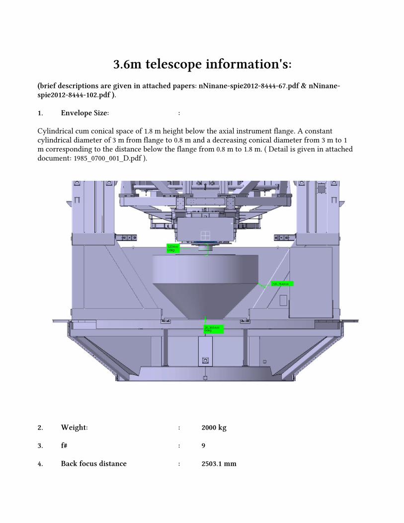
3.6m telescope information's:(brief descriptions are given in attached papers: nNinane-spie2012-8444-67.pdf & nNinane-spie2012-8444-102.pdf ).
1. Envelope Size: :
Cylindrical cum conical space of 1.8 m height below the axial instrument flange. A constant cylindrical diameter of 3 m from flange to 0.8 m and a decreasing conical diameter from 3 m to 1m corresponding to the distance below the flange from 0.8 m to 1.8 m. ( Detail is given in attached document: 1985_0700_001_D.pdf ).
2. Weight: : 2000 kg
3. f# : 9
4. Back focus distance : 2503.1 mm
ojha
Text Box
3.6m-specifications.pdf
5. Power budget :
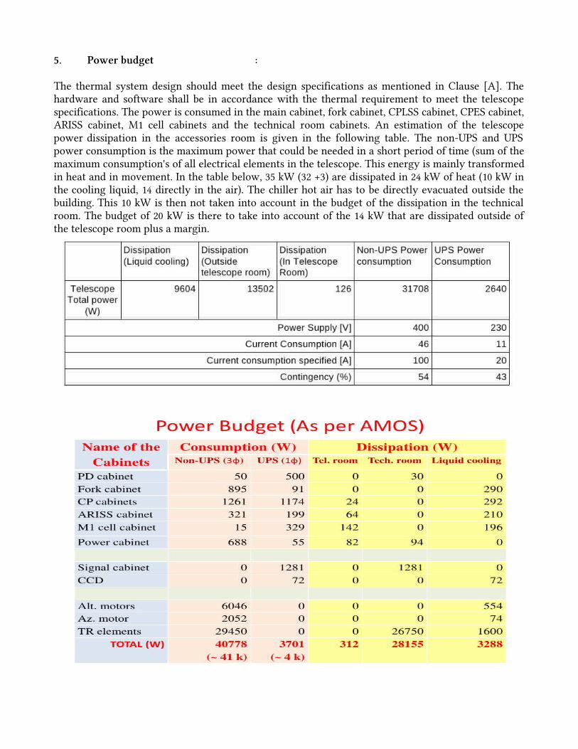
The thermal system design should meet the design specifications as mentioned in Clause [A]. The hardware and software shall be in accordance with the thermal requirement to meet the telescopespecifications. The power is consumed in the main cabinet, fork cabinet, CPLSS cabinet, CPES cabinet,ARISS cabinet, M1 cell cabinets and the technical room cabinets. An estimation of the telescope power dissipation in the accessories room is given in the following table. The non-UPS and UPS power consumption is the maximum power that could be needed in a short period of time (sum of the maximum consumption's of all electrical elements in the telescope. This energy is mainly transformed in heat and in movement. In the table below, 35 kW (32 +3) are dissipated in 24 kW of heat (10 kW in the cooling liquid, 14 directly in the air). The chiller hot air has to be directly evacuated outside the building. This 10 kW is then not taken into account in the budget of the dissipation in the technical room. The budget of 20 kW is there to take into account of the 14 kW that are dissipated outside of the telescope room plus a margin.
6. Software requirements :
The TCS runs under the LINUX platform within the Lab VIEW environment.
7. Can I use a closed cycle cooler : Yes ( D K Ojha???)8. Electronics location and space :Electronics can be placed on the instrument envelop or in the ground floor of the telescope which is 8 m below the telescope pier.
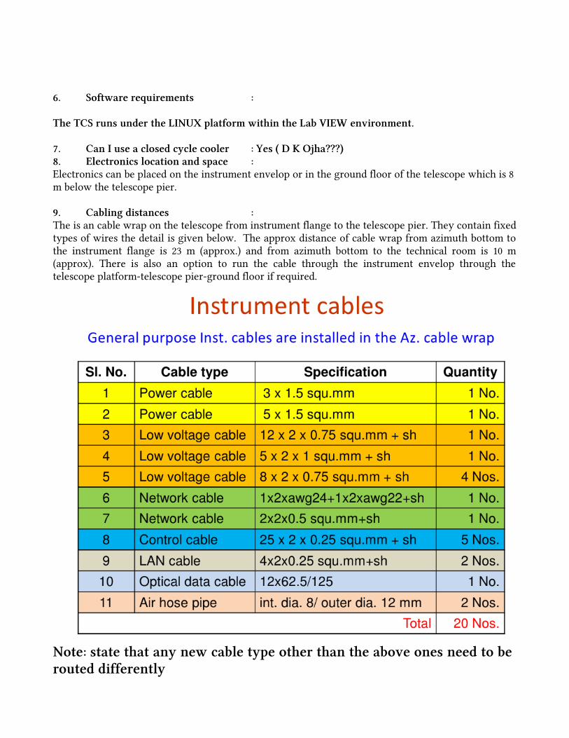
9. Cabling distances : The is an cable wrap on the telescope from instrument flange to the telescope pier. They contain fixed types of wires the detail is given below. The approx distance of cable wrap from azimuth bottom to the instrument flange is 23 m (approx.) and from azimuth bottom to the technical room is 10 m (approx). There is also an option to run the cable through the instrument envelop through the telescope platform-telescope pier-ground floor if required.
Note: state that any new cable type other than the above ones need to be routed differently

10. Any image data requirements : FITS file11. Telescope optical model : Detail is given in attached ZEMAX files:3.6m Telscope_Original design.SES 3.6m Telscope_Original design.ZMX
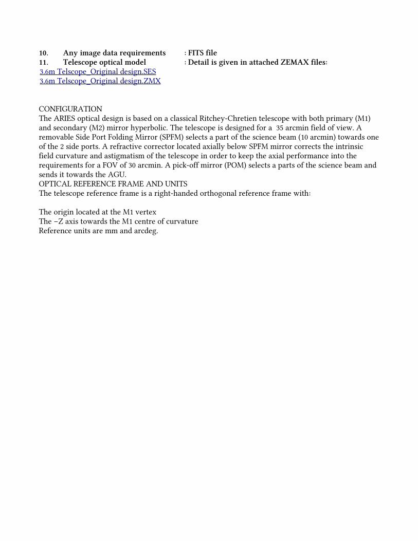
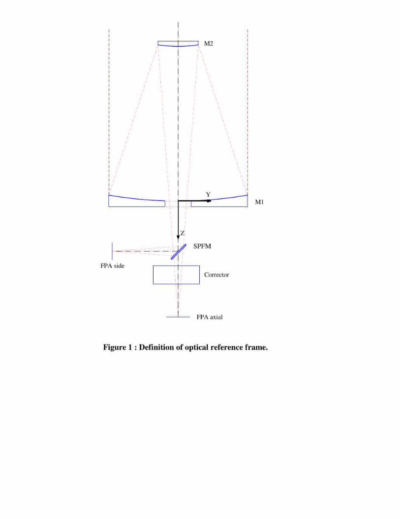
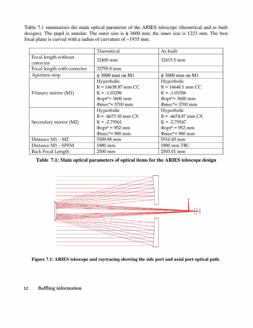
CONFIGURATIONThe ARIES optical design is based on a classical Ritchey-Chretien telescope with both primary (M1) and secondary (M2) mirror hyperbolic. The telescope is designed for a 35 arcmin field of view. A removable Side Port Folding Mirror (SPFM) selects a part of the science beam (10 arcmin) towards one of the 2 side ports. A refractive corrector located axially below SPFM mirror corrects the intrinsic field curvature and astigmatism of the telescope in order to keep the axial performance into the requirements for a FOV of 30 arcmin. A pick-off mirror (POM) selects a parts of the science beam and sends it towards the AGU. OPTICAL REFERENCE FRAME AND UNITSThe telescope reference frame is a right-handed orthogonal reference frame with:
The origin located at the M1 vertexThe –Z axis towards the M1 centre of curvatureReference units are mm and arcdeg.
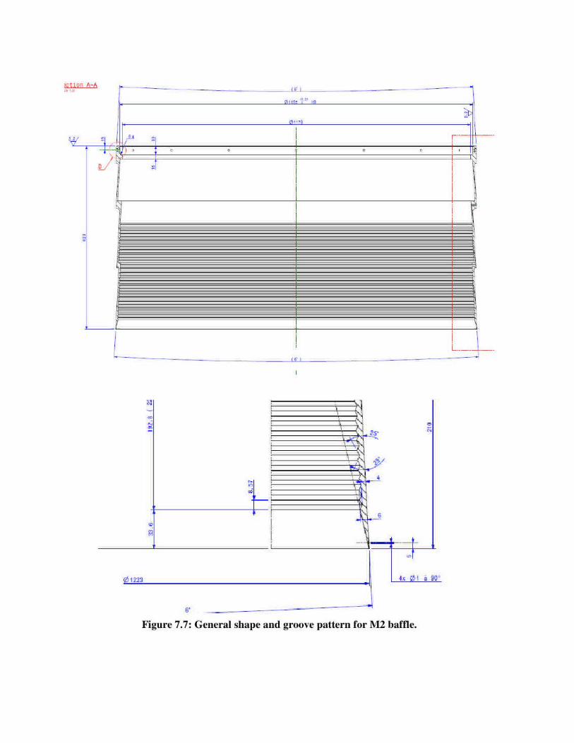
12. Baffling information


:


The 3,6 m Indo-Belgian Devasthal Optical Telescope: Assembly,Integration and Tests at AMOS
Nathalie Ninane, Christian Bastin, Jonathan de Ville, Fabrice Michel, Maxime Piérard, Eric Gabriel,Carlo Flebus and Amitesh Omar*
Advanced Mechanical and Optical Systems (AMOS s.a.), LIEGE Science Park, B-4031 ANGLEUR(Liège), BELGIUM
* Aryabhatta Research Institute of Observational Sciences (ARIES), Nainital, India
ABSTRACT
AMOS SA has been awarded of the contract for the design, manufacturing, assembly, tests and on site installation(Devasthal, Nainital in central Himalayan region) of the 3.6 m Indo-Belgian Devasthal Optical Telescope (IDOT).The telescope has a Ritchey-Chrétien optical configuration with a Cassegrain focus equipped with one axial port and twoside ports. The meniscus primary mirror is active and is supported by pneumatic actuators. The mount is an Alt–Az typewith for the azimuth axis a 5 m diameter hydrostatic track.The telescope was completely assembled and tested in AMOS workshop. This step is completed and successful. Thetelescope is now ready for shipment to Nainital.This paper describes the test campaign at sub-system and system level that has taken place to demonstrate that thetelescope satisfies the main system requirements. Besides of the functionality of the telescope, the units interacting withthe image quality or the tracking performance were plenty tested. Some selected tests directly connected to theperformance of the telescope are also looked specifically in this paper.
Keywords: telescope testing, IDOT
1. INTRODUCTION
In 2007, AMOS SA signed a contract for the design and building of a 4M class telescope with ARIES (AryabhattaResearch Institute of Observational Sciences) India. Today the telescope is constructed and ready to be shipped in India.The telescope will be installed at Devasthal, in the Himalayan range, 2500 m above the sea; 350 km North of Delhi.
The Telescope design(1) was presented 4 years ago at Marseille; since then it has been fully assembled and tested at sub-system and system levels in AMOS assembly hall.All along the integration and for each sub-system the functioning and the performances were verified as defined by thesystem engineering plan.Dummy mirrors as well as dummy instruments were used to perform the mechanical tests, to characterize and adjust thedrive of the axes, and to check the mirror integration procedures.When ready the mirrors were integrated and aligned in the telescope. Some optical tests were performed in sighting starsthrough an aperture made in AMOS integration hall roof. First images with a FWHM equal to 2.1 arcsec were recordeddespite of the bad seeing and thermal conditions. During these sky tests important functional tests were realised. Thecapability of the primary mirror correction with the active optic system was demonstrated. The mirror deformation modeswere generated and measured. The wavefront error correction loop was closed. Its convergence was checked.Tracking tests in open and close loops were also performed.
ojha
Text Box
nNinane-spie2012-8444-102.pdf
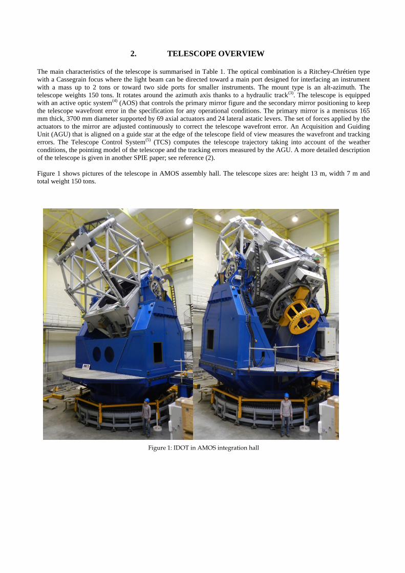
2. TELESCOPE OVERVIEW
The main characteristics of the telescope is summarised in Table 1. The optical combination is a Ritchey-Chrétien typewith a Cassegrain focus where the light beam can be directed toward a main port designed for interfacing an instrumentwith a mass up to 2 tons or toward two side ports for smaller instruments. The mount type is an alt-azimuth. Thetelescope weights 150 tons. It rotates around the azimuth axis thanks to a hydraulic track(3). The telescope is equippedwith an active optic system(4) (AOS) that controls the primary mirror figure and the secondary mirror positioning to keepthe telescope wavefront error in the specification for any operational conditions. The primary mirror is a meniscus 165mm thick, 3700 mm diameter supported by 69 axial actuators and 24 lateral astatic levers. The set of forces applied by theactuators to the mirror are adjusted continuously to correct the telescope wavefront error. An Acquisition and GuidingUnit (AGU) that is aligned on a guide star at the edge of the telescope field of view measures the wavefront and trackingerrors. The Telescope Control System(5) (TCS) computes the telescope trajectory taking into account of the weatherconditions, the pointing model of the telescope and the tracking errors measured by the AGU. A more detailed descriptionof the telescope is given in another SPIE paper; see reference (2).
Figure 1 shows pictures of the telescope in AMOS assembly hall. The telescope sizes are: height 13 m, width 7 m andtotal weight 150 tons.
Figure 1: IDOT in AMOS integration hall
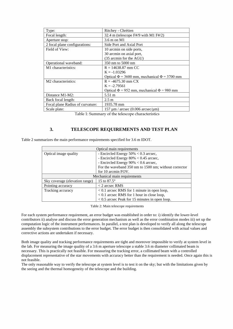
Type: Ritchey - ChrétienFocal length: 32.4 m (telescope F#/9 with M1 F#/2)Aperture stop: 3.6 m on M12 focal plane configurations: Side Port and Axial PortField of View: 10 arcmin on side ports,
30 arcmin on axial port,(35 arcmin for the AGU)
Operational waveband: 350 nm to 5000 nmM1 characteristics: R = 14638.87 mm CC
K = -1.03296Optical Φ = 3600 mm, mechanical Φ = 3700 mm
M2 characteristics: R = -4675.30 mm CXK = -2.79561Optical Φ = 952 mm, mechanical Φ = 980 mm
Distance M1-M2: 5.51 mBack focal length: 2.5 mFocal plane Radius of curvature: 1935.78 mmScale plate: 157 µm / arcsec (0.006 arcsec/µm)
Table 1: Summary of the telescope characteristics
3. TELESCOPE REQUIREMENTS AND TEST PLAN
Table 2 summarizes the main performance requirements specified for 3.6 m IDOT.
Optical main requirementsOptical image quality - Encircled Energy 50% < 0.3 arcsec,
- Encircled Energy 80% < 0.45 arcsec,- Encircled Energy 90% < 0.6 arcsec,For the waveband 350 nm to 1500 nm; without correctorfor 10 arcmin FOV.
Mechanical main requirementsSky coverage (elevation range) 15 to 87.5°Pointing accuracy < 2 arcsec RMSTracking accuracy < 0.1 arcsec RMS for 1 minute in open loop,
< 0.1 arcsec RMS for 1 hour in close loop,< 0.5 arcsec Peak for 15 minutes in open loop.
Table 2: Main telescope requirements
For each system performance requirement, an error budget was established in order to: i) identify the lower-levelcontributors ii) analyse and discuss the error generation mechanism as well as the error combination modes iii) set up thecomputation logic of the instrument performances. In parallel, a test plan is developed to verify all along the telescopeassembly the subsystem contributions to the error budget. The error budget is then consolidated with actual values andcorrective actions are undertaken if necessary.
Both image quality and tracking performance requirements are tight and moreover impossible to verify at system level inthe lab. For measuring the image quality of a 3.6 m aperture telescope a stable 3.6 m diameter collimated beam isnecessary. This is practically not feasible. For measuring the tracking error, a collimated beam with a controlleddisplacement representative of the star movements with accuracy better than the requirement is needed. Once again this isnot feasible.The only reasonable way to verify the telescope at system level is to test it on the sky; but with the limitations given bythe seeing and the thermal homogeneity of the telescope and the building.
The telescope was first integrated with dummy mirrors and instruments. The use of dummy mirrors presents some majoradvantages during AIV phase. First the mirrors are fragile and cost effective items; it is safer to check the integrationprocedures and perform a maximum of tests without any risk for them. Moreover mirrors are long lead items. Theintegration and tests can then start without waiting for the mirror delivery. And at last, dummies can be instrumentedeasily which simplifies the test preparations.
After the complete assembly of the telescope a electromechanical test and tuning campaign was undertaken. It consistedmainly in: The characterisations and the tuning of the axes (azimuth, elevation, adapter, rotator) that can be made onlytelescope fully assembled and balanced; Drive tests for actual axis trajectory cases, all axes working together. The result for one trajectory case is givenand explained in chapter 4. Functional tests of the telescope (except the tests that need a star light beam) ; Test of the integration procedures. The pieces to handle are big and heavy, and in the case of the mirrors fragile.No hazard for people or for the mirrors is allowed. Tube deflexion tests. The relative movements of the mirrors and of the instrument main interface have beenmeasured with a heterodyne interferometer for rotation of the tube between 15° and 90° and for temperature variations.Alignment correction laws of M2 in function of the elevation and temperature are introduced in the active optic system. Primary mirror jitter measurements that consists in recording and analysing the movements of the mirror in itscell up to 10 Hz for different tracking configurations.
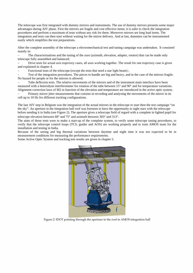
The last AIV step in Belgium was the integration of the actual mirrors in the telescope to start then the test campaign “onthe sky”. An aperture in the integration hall roof was foreseen to have the opportunity to sight stars with the telescopebefore sending it in India (see Figure 2). The aperture gives a telescope field of regard with a complete in lighted pupil for
telescope elevation between 68° and 75° and azimuth between 303° and 313°.The aims of those tests were to make a start-up of the complete system, to verify some telescope tuning procedures, toverify that the telescope control loops (TCS, guider and AOS) are working properly and to train AMOS team for theinstallation and testing in India.Because of the seeing and big thermal variations between daytime and night time it was not expected to be inmeasurement conditions for measuring the performance requirements.Some Active Optic System and tracking test results are given in chapter 5.
Figure 2: IDOT pointing through the aperture in the roof in AMOS integration hall
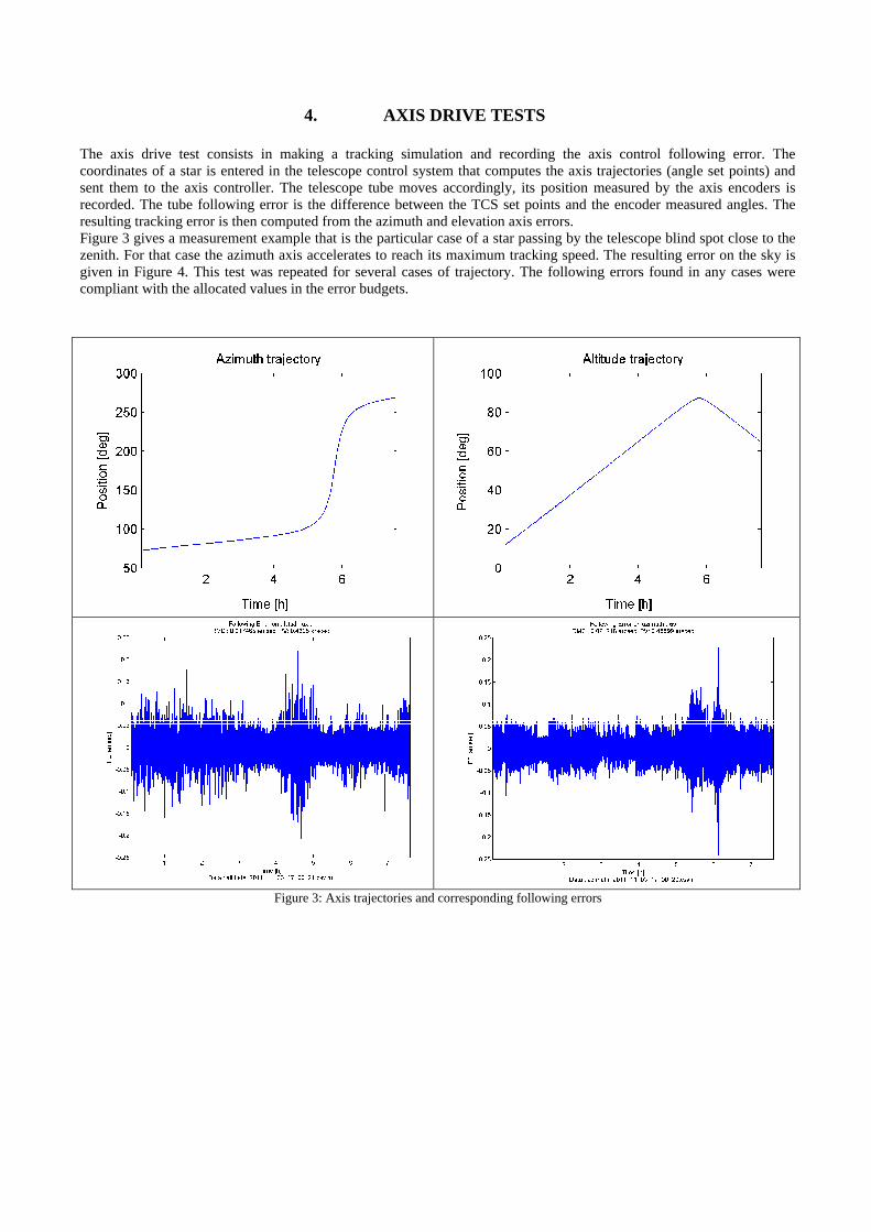
4. AXIS DRIVE TESTS
The axis drive test consists in making a tracking simulation and recording the axis control following error. Thecoordinates of a star is entered in the telescope control system that computes the axis trajectories (angle set points) andsent them to the axis controller. The telescope tube moves accordingly, its position measured by the axis encoders isrecorded. The tube following error is the difference between the TCS set points and the encoder measured angles. Theresulting tracking error is then computed from the azimuth and elevation axis errors.Figure 3 gives a measurement example that is the particular case of a star passing by the telescope blind spot close to thezenith. For that case the azimuth axis accelerates to reach its maximum tracking speed. The resulting error on the sky isgiven in Figure 4. This test was repeated for several cases of trajectory. The following errors found in any cases werecompliant with the allocated values in the error budgets.
Figure 3: Axis trajectories and corresponding following errors

Figure 4: Tracking error resulting from the following errors given in Figure 3; in blue the amplitude of the error, in black the RMSvalue of the error computed on a running time interval of 1 minute, in red the RMS value of the error computed on a running interval of
1 hour, in green the peak error on a running interval of 15 minutes.
5. SKY TESTS
5.1 Thermal environment
The sky tests were performed in AMOS integration hall (Belgium) between mid February and mid May 2012.Depending of the night, the temperatures were at the beginning of the night between 19°C and 8°C; with a drop duringthe night of about 10°C. During daytime, the hall temperature is around 20°C. In the evening the roof aperture and thehall outdoor were open to establish an air flux and reduce as much as possible the in and out temperature differences. Thethermal inertia of the primary mirror (M1) and the secondary (M2) are such that they stayed always few degrees abovethe ambient air. Table 3 gives typical temperature differences met during the sky tests.
Temperatures (°C) Beginning of the night End of the nightOutside temperature
(weather station) 17 7M1 edge +X 18.8 14
M1 centre front 18.4 14.8M1 centre back 18.6 15.5
Air just above M1 18.2 11.8M2 edge 19.4 14
M2 centre 19 15.2Table 3: Typical night temperature during the sky tests

5.2 FWHM and Wavefront Error
Depending of the night, the Full Width at Half Maximum (FWHM) of the star images were between 2.1 and 6arcseconds. Figure 5 gives an image recorded with the guider camera that gets a FWHM equal to 2.1 arcsec.
Figure 5: Image of HIP64532 (FWHM = 2.1 arcsec)
The wavefront error of the telescope was measured with the wavefront sensor of the AGU. It showed that therepeatability of the measurement was poor but coherent with the seeing; and that the spherical aberration drifted duringthe night; this is correlated with the radial thermal gradients in the primary mirror.Figure 6 a. shows Focus and Spherical Aberration repeatability for an integration time of 10 s and a FWHM = 2.8 arcsec.The repeatability’s for different exposure times and the coefficients measured by the WFS are in Figure 6 b.
a. b.
Figure 6: WFE repeatability (FWHM = 2.8 arcsec),); a) Focus and spherical aberration (t =10 s) , b) Focus (foc), Astigmatism (Ax &Ay), Coma (Cx & Cy), Spherical aberration (Sph), Trifold (3Fx & 3Fy), Quadrifold (4Fx & 4Fy) for different exposure times
The wavefront error repeatability is the test limitation for the active optic system.
1 arcsec
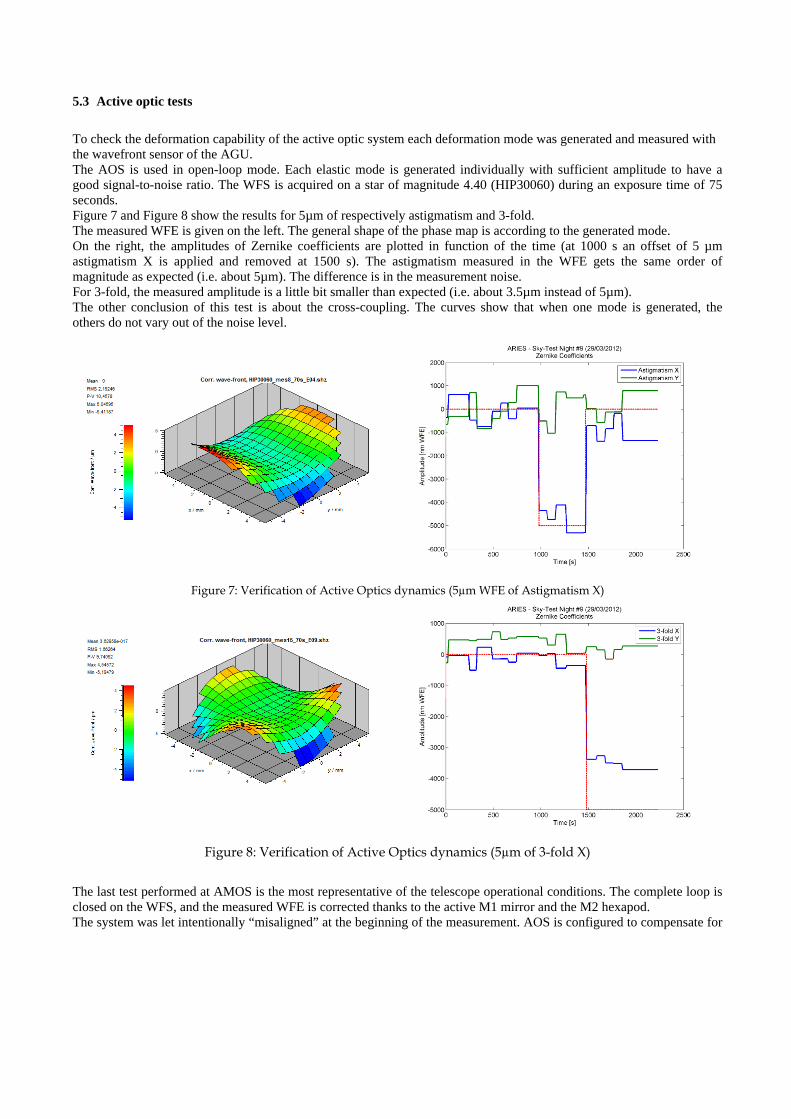
5.3 Active optic tests
To check the deformation capability of the active optic system each deformation mode was generated and measured withthe wavefront sensor of the AGU.The AOS is used in open-loop mode. Each elastic mode is generated individually with sufficient amplitude to have agood signal-to-noise ratio. The WFS is acquired on a star of magnitude 4.40 (HIP30060) during an exposure time of 75seconds.Figure 7 and Figure 8 show the results for 5µm of respectively astigmatism and 3-fold.The measured WFE is given on the left. The general shape of the phase map is according to the generated mode.On the right, the amplitudes of Zernike coefficients are plotted in function of the time (at 1000 s an offset of 5 µmastigmatism X is applied and removed at 1500 s). The astigmatism measured in the WFE gets the same order ofmagnitude as expected (i.e. about 5µm). The difference is in the measurement noise.For 3-fold, the measured amplitude is a little bit smaller than expected (i.e. about 3.5µm instead of 5µm).The other conclusion of this test is about the cross-coupling. The curves show that when one mode is generated, theothers do not vary out of the noise level.
Figure 7: Verification of Active Optics dynamics (5µm WFE of Astigmatism X)
Figure 8: Verification of Active Optics dynamics (5µm of 3-fold X)
The last test performed at AMOS is the most representative of the telescope operational conditions. The complete loop isclosed on the WFS, and the measured WFE is corrected thanks to the active M1 mirror and the M2 hexapod.The system was let intentionally “misaligned” at the beginning of the measurement. AOS is configured to compensate for

astigmatism, 3-fold and spherical aberration with M1 active support. Focus and coma are corrected in moving M2 thanksto the hexapod.The closed-loop test is run on Edasich (magnitude 3.25) with an exposure time of 10 seconds. In addition to the WFSintegration, the Active Optics System is configured to compensate only 20% of the measured coefficients at eachiteration, in order to filter the seeing (and avoid “correcting” it). The active optics correction has thus a time-constant of50 seconds.
Figure 9 presents the results. The amplitude of focus and spherical aberration are given on the left. The first 800 secondsare in open-loop. In average, the WFE contains about 3500 nm WFE of focus and -800 nm WFE of spherical aberration.After the closed-loop is switched on, these modes clearly converge around zero.The WFE RMS (without piston and tilts) is shown on the right. In open-loop, the optical quality was about 2200 nmRMS WFE. Closing the loop improves the WFE down to 750 nm RMS. It oscillates between 500 and 1000 nm RMS dueto the seeing conditions. An analysis of the system shows that a WFE RMS = 750 nm corresponds to an EE50% ~1arcsec at 500 nm.
Figure 9: Active Optics in closed-loop (left: focus and spherical aberration – right: WFE rms)
5.4 Tracking tests
After elaboration of a pointing model through the field of regard, some tracking error tests were performed in open andclose loop. The guider camera sights one star in the telescope field of view while a test camera records and analyses theimages of a second star at the centre of the telescope field of view. The positions of the successive star centroids on thetest camera give the tracking error. Figure 8 shows the measurement results. They give a tracking error of 0.25 arcsecRMS, the image integration time equal to 30 s and the FWHM was 2.5 arcsec. Other measurements showed that theresults depend directly on the seeing and the integration time.This test gives an upper limit of the tracking error; it cannot distinguish the effect of the seeing from the telescope itself.

Tracking error in close loop; RMS: 0.25 arcsec, Peak: 0.51 arcsec
-0.60
-0.40
-0.20
0.00
0.20
0.40
0.60
3:41:46 3:44:38 3:47:31 3:50:24 3:53:17 3:56:10 3:59:02 4:01:55 4:04:48 4:07:41
time
arc
se
c dX
dY
dP
Figure 8: Tracking error measurement; in blue the centroid moves along X, in pink along Y, in yellow the amplitude of theerror
6. CONCLUSIONS
IDOT was completely assembled in AMOS premises. During this AIV phase, tests at subsystem and system level wereperformed to guaranty the telescope specifications. The last test campaign was performed with actual mirrors, pointingstars through an aperture in the integration hall roof. Despite that AMOS hall is not a dome and Liège not an astronomicalsite, the sky tests were very useful. They have enabled to test all the functionalities of the telescope. All the subsysteminterfaces were checked by this way. The guiding loop was tested and used. The active optic system functionalities weretried and adjusted.Images with FWHM of 2.1 arcsec were a very good surprise given the test conditions.Moreover the sky tests were a very good training exercise for AMOS AIV engineering team. The procedures werechecked and corrected. These last points are useful for the preparation of the commissioning campaign.Now the telescope is ready to be sent on site in India where it will be assembled by AMOS. Final tuning and performancetests will then be done in actual operating conditions.
7. ACKNOWLEDGEMENT
This work has been performed under ARIES contract reference 1985-14-02. AMOS is very grateful towards ARIES teamfor having put their confidence in AMOS team for the design and manufacturing of the 3.6 m telescope.
8. REFERENCES
(1) Flebus C., Gabriel E., Lambotte S., Pierard M., Rausin F., Schumacher J.M. and Ninane N., "Opto-mechanicaldesign of the 3,6 m Optical Telescope for ARIES", Proc. SPIE 7012-09 (2008).
(2) N. Ninane & Co., “The 3.6 m Indo-Belgian Devasthal Optical Telescope: general description”, Proc. SPIE8444-67 (2012)
(3) Deville J., Bastin C. and Pierard M., "The 3.6 m Indo-Belgian Devasthal Optical Telescope: the hydrostaticazimuth bearing", Proc. SPIE 8444-150 (2012)
(4) Pierard M., Schumacher J.M., Flebus C. and Ninane N., "The 3.6 m Indo-Belgian Devasthal Optical Telescope:the active M1 mirror support", Proc. SPIE 8444-186 (2012)
(5) Gabriel E., Bastin C., Pierard M. - “The 3.6 m Indo-Belgian Devasthal Optical Telescope: the control system”,Proc. SPIE 8451-82 (2012)

The 3,6 m Indo-Belgian Devasthal Optical Telescope :
General description
Nathalie Ninane, Carlo Flebus and Brijesh Kumar*
Advanced Mechanical and Optical Systems (AMOS s.a.), LIEGE Science Park, B-4031 ANGLEUR
(Liège), BELGIUM
* Aryabhatta Research Institute of Observational Sciences (ARIES), Manora Peak, Nainital, 263 129
India
ABSTRACT
AMOS SA has been awarded of the contract for the design, manufacturing, assembly, tests and on site installation
(Devasthal, Nainital in central Himalayan region) of the 3.6 m Indo-Belgian Devasthal Optical Telescope (IDOT).
The telescope has Ritchey-Chrétien optical configuration with one axial and two side Cassegrain ports. The meniscus
primary mirror is active and it is supported by pneumatic actuators. The azimuth axis system is equipped with hydrostatic
bearing.
The telescope was completely assembled and tested in AMOS workshop. This step is completed and successful. The
telescope is now ready for shipment to Nainital.
This paper describes the telescope and summarizes the test results performed at AMOS to demonstrate that the telescope
satisfies the main system requirements.
Keywords: telescope tests, hydrostatic, active optics, mirror supports, IDOT
1. INTRODUCTION
In 2007, AMOS SA signed a contract for the design and building of a 4M class telescope with ARIES (Aryabhatta
Research Institute of Observational Sciences) India. Today the telescope is constructed and ready to be shipped in India.
The telescope will be installed at Devasthal, in the Himalayan range, 2500m above the sea; 350 km North of Delhi.
The optical combination is a Ritchey-Chrétien type with a Cassegrain focus where the light beam can be directed toward
a main port designed for interfacing an instrument with a mass up to 2 tons or toward two side ports for smaller
instruments. The primary mirror unit is an active system that controls the mirror figure to keep the telescope wavefront
error in the specification for any operational conditions. The mount type is an alt-azimuth. The Telescope design was
presented (1) 4 years ago at Marseille; since then it has been fully assembled and tested at sub-system and system levels in
AMOS assembly hall.
This paper starts with a reminding of the specifications and the optical design. Then an overview of the as built telescope
and a presentation of the tests made in factory are given.
Ground-based and Airborne Telescopes IV, edited by Larry M. Stepp, Roberto Gilmozzi, Helen J. Hall, Proc. of SPIE Vol. 8444, 84441V · © 2012 SPIE · CCC code: 0277-786/12/$18 · doi: 10.1117/12.925921
Proc. of SPIE Vol. 8444 84441V-1
ojha
Text Box
nNinane-spie2012-8444-671.pdf
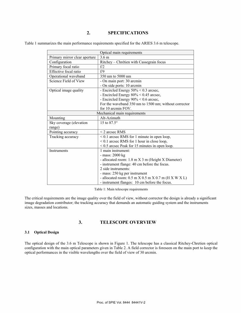
2. SPECIFICATIONS
Table 1 summarizes the main performance requirements specified for the ARIES 3.6 m telescope.
Optical main requirements
Primary mirror clear aperture 3.6 m
Configuration Ritchey – Chrétien with Cassegrain focus
Primary focal ratio f/2
Effective focal ratio f/9
Operational waveband 350 nm to 5000 nm
Science Field of View - On main port: 30 arcmin
- On side ports: 10 arcmin
Optical image quality - Encircled Energy 50% < 0.3 arcsec,
- Encircled Energy 80% < 0.45 arcsec,
- Encircled Energy 90% < 0.6 arcsec,
For the waveband 350 nm to 1500 nm; without corrector
for 10 arcmin FOV.
Mechanical main requirements
Mounting Alt-Azimuth
Sky coverage (elevation
range)
15 to 87.5°
Pointing accuracy < 2 arcsec RMS
Tracking accuracy < 0.1 arcsec RMS for 1 minute in open loop,
< 0.1 arcsec RMS for 1 hour in close loop,
< 0.5 arcsec Peak for 15 minutes in open loop.
Instruments 1 main instrument:
- mass: 2000 kg
- allocated room: 1.8 m X 3 m (Height X Diameter)
- instrument flange: 40 cm before the focus.
2 side instruments:
- mass: 250 kg per instrument
- allocated room: 0.5 m X 0.5 m X 0.7 m (H X W X L)
- instrument flanges: 10 cm before the focus.
Table 1: Main telescope requirements
The critical requirements are the image quality over the field of view, without corrector the design is already a significant
image degradation contributor; the tracking accuracy that demands an automatic guiding system and the instruments
sizes, masses and locations.
3. TELESCOPE OVERVIEW
3.1 Optical Design
The optical design of the 3.6 m Telescope is shown in Figure 1. The telescope has a classical Ritchey-Chretien optical
configuration with the main optical parameters given in Table 2. A field corrector is foreseen on the main port to keep the
optical performances in the visible wavelengths over the field of view of 30 arcmin.
Proc. of SPIE Vol. 8444 84441V-2
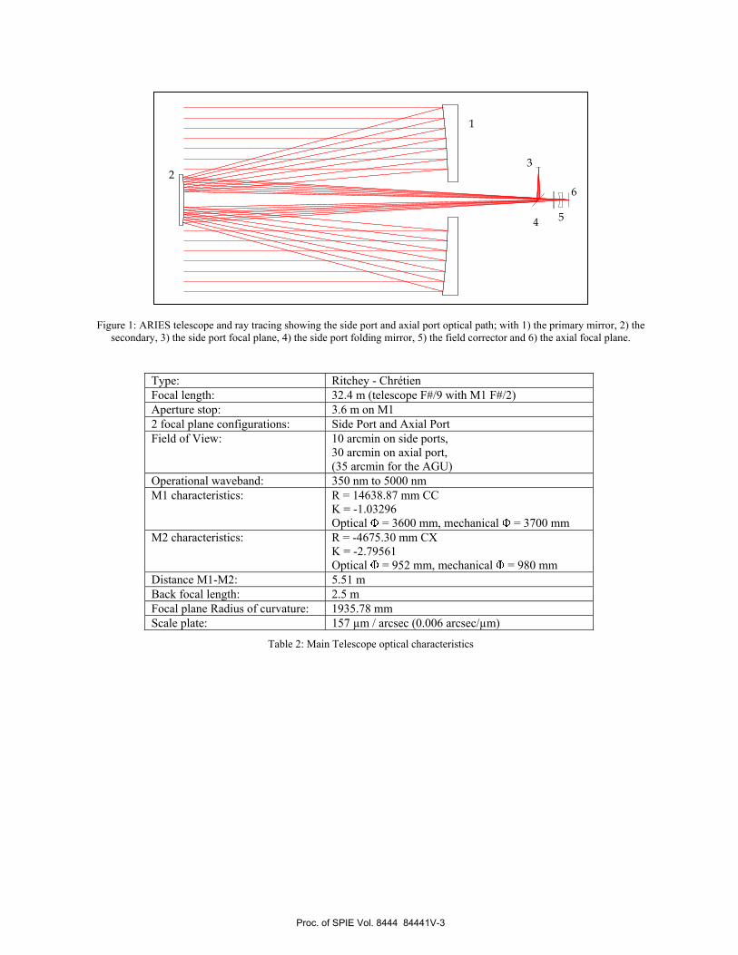
Figure 1: ARIES telescope and ray tracing showing the side port and axial port optical path; with 1) the primary mirror, 2) the
secondary, 3) the side port focal plane, 4) the side port folding mirror, 5) the field corrector and 6) the axial focal plane.
Type: Ritchey - Chrétien
Focal length: 32.4 m (telescope F#/9 with M1 F#/2)
Aperture stop: 3.6 m on M1
2 focal plane configurations: Side Port and Axial Port
Field of View: 10 arcmin on side ports,
30 arcmin on axial port,
(35 arcmin for the AGU)
Operational waveband: 350 nm to 5000 nm
M1 characteristics: R = 14638.87 mm CC
K = -1.03296
Optical = 3600 mm, mechanical = 3700 mm
M2 characteristics: R = -4675.30 mm CX
K = -2.79561
Optical = 952 mm, mechanical = 980 mm
Distance M1-M2: 5.51 m
Back focal length: 2.5 m
Focal plane Radius of curvature: 1935.78 mm
Scale plate: 157 µm / arcsec (0.006 arcsec/µm)
Table 2: Main Telescope optical characteristics
1
2
3
4 5
6
Proc. of SPIE Vol. 8444 84441V-3
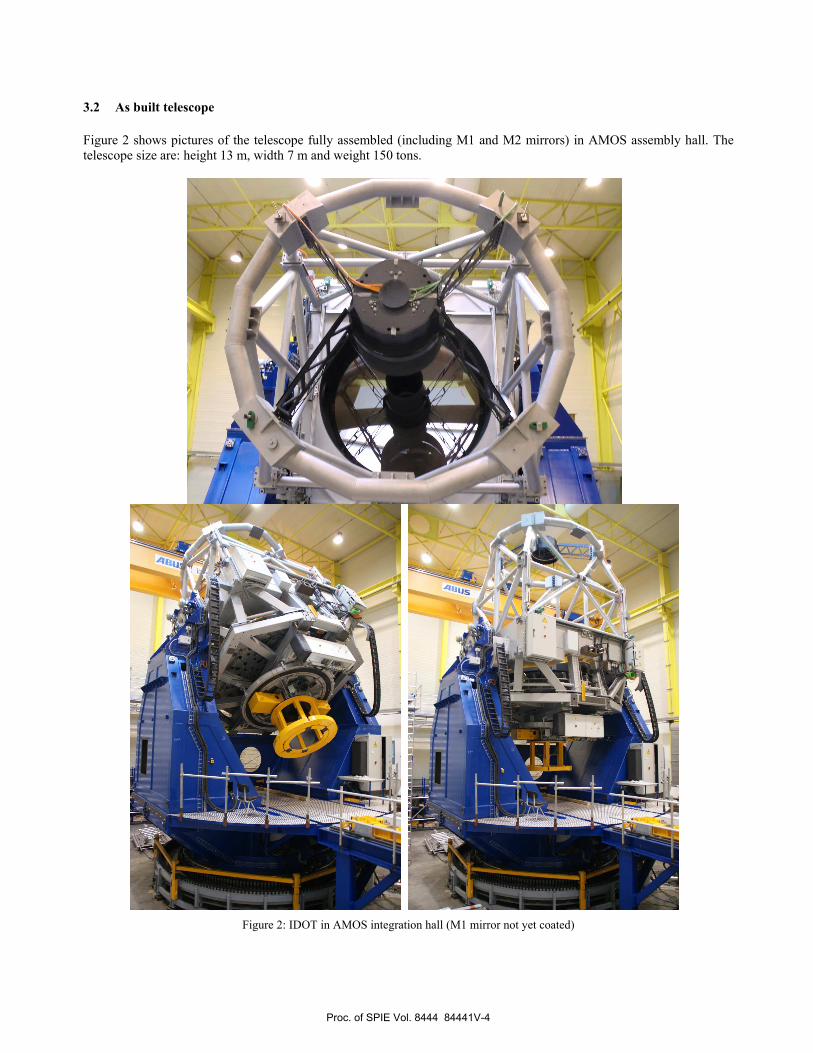
3.2 As built telescope
Figure 2 shows pictures of the telescope fully assembled (including M1 and M2 mirrors) in AMOS assembly hall. The
telescope size are: height 13 m, width 7 m and weight 150 tons.
Figure 2: IDOT in AMOS integration hall (M1 mirror not yet coated)
Proc. of SPIE Vol. 8444 84441V-4
The general mechanical design was driven by optical and mechatronic requirements needed to reach telescope
performance specifications for any operational conditions. Its stiffness enables a very accurate control of the axis
movements. It is based on Serrurier truss to minimize the misalignment between M1, M2 and the focal plane while
tracking. High precision bearings were selected to guaranty very smooth movements.
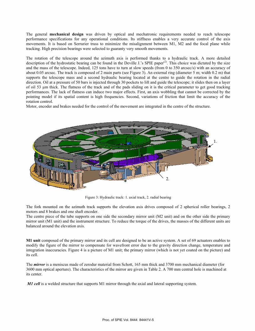
The rotation of the telescope around the azimuth axis is performed thanks to a hydraulic track. A more detailed
description of the hydrostatic bearing can be found in the Deville J.’s SPIE paper(2). This choice was dictated by the size
and the mass of the telescope. Indeed, 125 tons have to turn at slow speeds (from 0 to 350 arcsec/s) with an accuracy of
about 0.05 arcsec. The track is composed of 2 main parts (see Figure 3). An external ring (diameter 5 m; width 0.2 m) that
supports the telescope mass and a second hydraulic bearing located at the centre to guide the rotation in the radial
direction. Oil at a pressure of 50 bars is injected through 30 pockets to lift and guide the telescope; it slides then on a layer
of oil 53 µm thick. The flatness of the track and of the pads sliding on it is the critical parameter to get good tracking
performances. The lack of flatness can induce two major effects. First, an axis wobbling that cannot be corrected by the
pointing model if its spatial content is high frequencies. Second, variations of friction that limit the accuracy of the
rotation control.
Motor, encoder and brakes needed for the control of the movement are integrated in the centre of the structure.
Figure 3: Hydraulic track: 1. axial track, 2. radial bearing
The fork mounted on the azimuth track supports the elevation axis drives composed of 2 spherical roller bearings, 2
motors and 8 brakes and one shaft encoder.
The centre piece of the tube supports on one side the secondary mirror unit (M2 unit) and on the other side the primary
mirror unit (M1 unit) and the instrument structure. To reduce the torque of the drives, the masses of the different units are
balanced around the elevation axis.
M1 unit composed of the primary mirror and its cell are designed to be an active system. A set of 69 actuators enables to
modify the figure of the mirror to compensate for wavefront error due to the gravity direction change, temperature and
integration inaccuracies. Figure 4 is a picture of M1 unit; the primary mirror (which is not yet coated on the picture) and
its cell.
The mirror is a meniscus made of zerodur material from Schott, 165 mm thick and 3700 mm mechanical diameter (for
3600 mm optical aperture). The characteristics of the mirror are given in Table 2. A 700 mm central hole is machined at
its center.
M1 cell is a welded structure that supports M1 mirror through the axial and lateral supporting system.
1.
2.
Proc. of SPIE Vol. 8444 84441V-5

The axial support consists of 69 pneumatic actuators (active optics).The number and the positions of these actuators have
been optimized using FEM. There are distributed on 4 rings. The 69 supports are pneumatic actuators working in “Push
only” mode. Their range in force is equal to 1000 N. The gravity load of the mirror on the actuators acts as the “pulling
mode”. The surface figure is modified in changing the force distribution of the overall actuators in keeping the sum of the
forces equal to the weight of the mirror. A detailed description of this active system is given by M. Piérard(3) in a
dedicated SPIE paper.
The lateral support consists of 24 classical astatic lever counterweights. To converge to the allocated error budget, it was
necessary (mainly due to the large residual COMA aberration) to incline these levers in two directions.
Figure 4: M1 unit: the mirror (1); an axial actuator (2); an astatic lever (3); a counterweight (4).
M2 unit is composed with the secondary mirror, the cell with axial and lateral supports and its interface with a hexapod
mechanism.
M2 mirror is made of Sitall C0115M material from LZOS (Russia). The optical characteristics of M2 mirror are given in
Table 2.
The axial support is a 6-point single stage whiffle tree. The lateral support consists of a central blade.
M2 cell is interfaced to a Hexapod mechanism providing defocus, de-centering and tip-tilt motions.
Figure 5: M2 unit: front side and rear side ((1) the central blade; (2) the whiffle tree)
1
2 4
3
1 2
Proc. of SPIE Vol. 8444 84441V-6
The polishing and testing of M1 and M2 mirrors has been sub-contracted to LZOS (Russia) (4) under the supervision of
AMOS experts.
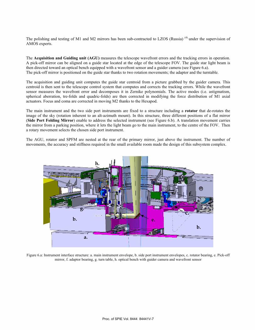
The Acquisition and Guiding unit (AGU) measures the telescope wavefront errors and the tracking errors in operation.
A pick-off mirror can be aligned on a guide star located at the edge of the telescope FOV. The guide star light beam is
then directed toward an optical bench equipped with a wavefront sensor and a guider camera (see Figure 6.a).
The pick-off mirror is positioned on the guide star thanks to two rotation movements; the adaptor and the turntable.
The acquisition and guiding unit computes the guide star centroid from a picture grabbed by the guider camera. This
centroid is then sent to the telescope control system that computes and corrects the tracking errors. While the wavefront
sensor measures the wavefront error and decomposes it in Zernike polynomials. The active modes (i.e. astigmatism,
spherical aberration, tre-folds and quadric-folds) are then corrected in modifying the force distribution of M1 axial
actuators. Focus and coma are corrected in moving M2 thanks to the Hexapod.
The main instrument and the two side port instruments are fixed to a structure including a rotator that de-rotates the
image of the sky (rotation inherent to an alt-azimuth mount). In this structure, three different positions of a flat mirror
(Side Port Folding Mirror) enable to address the selected instrument (see Figure 6.b). A translation movement carries
the mirror from a parking position, where it lets the light beam go to the main instrument, to the centre of the FOV. Then
a rotary movement selects the chosen side port instrument.
The AGU, rotator and SPFM are nested at the rear of the primary mirror, just above the instrument. The number of
movements, the accuracy and stiffness required in the small available room made the design of this subsystem complex.
Figure 6.a: Instrument interface structure: a. main instrument envelope, b. side port instrument envelopes, c. rotator bearing, e. Pick-off
mirror, f. adaptor bearing, g. turn table, h. optical bench with guider camera and wavefront sensor
a.
b.
b.
c. e.
f.
g.
h.
Proc. of SPIE Vol. 8444 84441V-7

Figure 6.b: SPFM positioned to address a side port
Telescope control system
Computers and PLC are used for the telescope control at system and subsystem level including the reading of sensors that
are used for operation and safety purposes. The control system architecture is given in Figure 7.
The operator interface is done via two computers. One on which the Telescope Control System software (TCS) is
installed. This software deals mainly with the computation of the axis movements. Starting from the target and guide stars
coordinates, it takes into account of the weather parameters, the pointing model of the telescope and the pointing
correction measured by the guider to compute in real time the angular positions of the telescope axes (Azimuth, Altitude,
Rotator and Adaptor). These positions are then sent to the mount control system (UMAC).
Moreover the TCS collects all the safety sensors; the operator is warned in case of anomaly and can consult the status of
all the subsystems from this computer. A more detailed description of the TCS is given by E. Gabriel & all (5) in SPIE
paper.
The set-up and the control of the Active Optic System (AOS) are managed from the second computer. It includes M1 cell
control, the wavefront measurement, the computation of M1 axial forces and M2 movements. The status of the
subsystems linked to the active optic system (M1 cell, Hexapod, wavefront sensor) is displayed continuously on the AOS
computer screen. The values measured by the sensors involved in the AO can be directly read through different menu.
Telescope Control System
(TCS)Mount Control System (UMAC):
Azimuth, Altitude, Rotator, Adapter, SAT, SAF
(Synchronized connection for tracking performance)
Active Optics System
(AOS)
Auto Guiding Unit
(AGU)
M1 Actuators:Set-points, force value, pressure value, errors
M2 Hexapod:Focus, Centring, Tilts: setpoints, values, errors
Weather Station:Temperature, Humidity, Pressure
Auto Guiding Unit CCDGuide Star picture
Axes
positionsGlobal
status
Status,
Centroid
movement
Closed loop
activation
Safety, Azimuth Aux, Counterweights, M1 Cover,
SPFM, OF, Thermal Control, Compressed Air
M1 definers, lateral levers, temperatures
M2 temperatures
PLC
SHSworksWave Front Sensor control
Acquisition
control
WFE rms
Zernike coeff
Wave Front Sensor CCDGuide Star Wave Front picture
Telescope Control System
(TCS)Mount Control System (UMAC):
Azimuth, Altitude, Rotator, Adapter, SAT, SAF
(Synchronized connection for tracking performance)
Active Optics System
(AOS)
Auto Guiding Unit
(AGU)
M1 Actuators:Set-points, force value, pressure value, errors
M2 Hexapod:Focus, Centring, Tilts: setpoints, values, errors
Weather Station:Temperature, Humidity, Pressure
Auto Guiding Unit CCDGuide Star picture
Axes
positionsGlobal
status
Status,
Centroid
movement
Closed loop
activation
Safety, Azimuth Aux, Counterweights, M1 Cover,
SPFM, OF, Thermal Control, Compressed Air
M1 definers, lateral levers, temperatures
M2 temperatures
PLC
Safety, Azimuth Aux, Counterweights, M1 Cover,
SPFM, OF, Thermal Control, Compressed Air
M1 definers, lateral levers, temperatures
M2 temperatures
PLC
SHSworksWave Front Sensor control
Acquisition
control
WFE rms
Zernike coeff
Wave Front Sensor CCDGuide Star Wave Front picture
Figure 7: Telescope control system architecture
Proc. of SPIE Vol. 8444 84441V-8

4. ASSEMBLY, INTEGRATION AND VERIFICATION
The telescope was fully assembled in AMOS integration hall. All along the integration and for each sub-system the
functioning and the performances were verified as defined by the system engineering plan (see details in SPIE paper (6)).
Dummy mirrors as well as dummy instruments were used to perform the mechanical tests, to characterize and adjust the
drive of the axes, and to check the mirror integration procedures.
When ready the mirrors were integrated and aligned in the telescope. Some optical tests were performed in sighting stars
through an aperture made in AMOS integration hall roof (see Figure 8). First images with a FWHM equal to 2.1 arcsec
were recorded despite of the bad seeing and thermal conditions. With these sky tests important functional tests were
realised. The capability of the primary mirror correction with the active optic system was demonstrated. The mirror
deformation modes were generated and measured (see Figure 10). The wavefront error correction loop was closed. Its
convergence was checked.
Tracking tests in open and close loop were successfully performed.
Preparation and testing have been pushed as far as possible in lab conditions, the telescope is now ready to be sent and
installed on site in India with a limited risk.
Figure 8: Sky test configuration in AMOS integration hall
Proc. of SPIE Vol. 8444 84441V-9
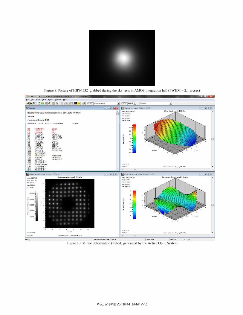
Figure 9: Picture of HIP64532 grabbed during the sky tests in AMOS integration hall (FWHM = 2.1 arcsec)
Figure 10: Mirror deformation (trefoil) generated by the Active Optic System
Proc. of SPIE Vol. 8444 84441V-10

5. ACKNOWLEDGEMENT
This work has been performed under ARIES contract reference 1985-14-02. AMOS is very grateful towards ARIES team
for having put their confidence in AMOS team for the design and manufacturing of the 3.6 m telescope.
6. REFERENCES
1. Flebus C., Gabriel E., Lambotte S., Pierard M., Rausin F., Schumacher J.M. and Ninane N., "Opto-mechanical
design of the 3,6 m Optical Telescope for ARIES", Proc. SPIE 7012-09 (2008).
2. Deville J., Bastin C. and Pierard M., "The 3.6 m Indo-Belgian Devasthal Optical Telescope: the hydrostatic
azimuth bearing",Proc. SPIE 8444-150 (2012)
3. Pierard M., Schumacher J.M., Flebus C. and Ninane N., "The 3.6 m Indo-Belgian Devasthal Optical Telescope:
the active M1 mirror support", Proc. SPIE 8444-186 (2012)
4. Aleksandr P. Semenov, Lytkarino Optical Glass Factory JSC (Russian Federation) – “Accomplished the task of
production of primary and secondary mirrors of DOT telescope under the project ARIES (India, Belgium,
Russia): fabrication features”, Proc. SPIE 8450-176 (2012)
5. Gabriel E., Bastin C., Pierard M. - “The 3.6 m Indo-Belgian Devasthal Optical Telescope: the control system”,
Proc. SPIE 8451-82 (2012)
6. Ninane N., Bastin C., Deville J., Michel F., Pierard M., Gabriel E., Flebus C. and Omar A., "The 3.6 m Indo-
Belgian Devasthal Optical Telescope: assembly, integration, and tests at AMOS", Proc. SPIE 8444-102 (2012)
Proc. of SPIE Vol. 8444 84441V-11

Welding
Machining
Final − to be ArchivedAs−BuiltCertified for ApplicationApproved for Lay−out FIN :ASB :CFA :AFL :
AE DIN 8570
DIN 7168−f−RTolerances :
A1Format
02Document
ADVANCED MECHANICAL AND OPTICAL SYSTEMS
Parc Scientifique du Sart−Tilmanrue des Chasseurs ArdennaisB−4031 ANGLEUR [BELGIUM]
SA.
Orig.Ref. CATIA
Scale
NameDate
Checked
Drawn
IssueDrawing
Product Item
Drawing − Remarks − MaterialRep.Nbr
NameEns
R:\1985_ARIES\ARI−DWG−AMO−0000(telescop)\1985−0700−(ARISS)\JANVIER 2009 CURENT\1985_0700_001
Treatment :
Mass.:−−Kg.
−
−
−TELESCOPE INTERFACES
WITH INSTRUMENTS
Sheet
1/10
19−01−09 MCU
1985 − ARIES 3.6M − TELESCOPE
D
− −
1/1
75(4
X)
560= =
FACE VIEW
110
2765 (altitude axis)
16M(2X10)
A
A
135
380
1000
170
130
800
1800
1000Ø
3000Ø
3040
620
SECTION A−ASCALE:1/10
FP
AZIMUTH AXIS
FP
COG
COG
AXIAL INSTUMENT
SECONDARY INSTRUMENT
2765 (altitude axis)
95Ø
620
330Ø
100
620
800
440
B B
C
300
==
1000
10(36X)
1440
18(36X) (TO DRILL)
1500( )
SECTION B−BSCALE:1/10
Ø0.3
520
500
30(
)
DETAIL CSCALE:1/2
1500 0−0.3Ø (SHAFT)
ojha
Text Box
tel-072-2010-02_1985_0700_001_D-ICDrawing.pdf

Zemax Ray Trace of 3.6m Telescope (f/9)
ojha
Text Box
3.6m Telscope_Original design.SES & 3.6m Telscope_Original design.ZMX (ZMX and SES files available on request to the purchase officer, TIFR)

Spot Diagram

Diffraction Encircled Energy

Zemax Prescription