Task 5: Determination of a methodology for testing,...
30
Annex E E1 Annex E Determination of a methodology for testing, validation and certification Partner: Deutsche Montan Technologie GmbH Fachstelle für leittechnische Einrichtungen mit Sicherheitsverantwortung Beylingstr. 65, D - 44329 Dortmund Authors: Dr. Franz Eickhoff Dr. Michael Unruh
Transcript of Task 5: Determination of a methodology for testing,...

Annex EE1
Annex E
Determination of a methodology for testing, validationand certification
Partner: Deutsche Montan Technologie GmbHFachstelle für leittechnische Einrichtungen mitSicherheitsverantwortungBeylingstr. 65, D - 44329 Dortmund
Authors: Dr. Franz EickhoffDr. Michael Unruh
E2 Annex E
Content1 Introduction E4
1.1 Working task E41.2 Definition of safety devices and applicable technologies E4
1.2.1 Conclusions out of the ATEX-Guidelines E5
2 Requirements E72.1 Requirements of directives 94/9/EC and 1999/92/EC E72.2 Summary of demands out of 94/9/EC and 1999/92/EC E8
3 Selection of concept for certification E83.1 Concept of EN 1441 [9] E83.2 Concept of harmonised standards under the scope of directive 98/37/EC E93.3 Concept of IEC 61 508 E103.4 Assignment of IEC 61508 lifecycles to the area of explosion protection E13
3.4.1 Conclusion for IEC 61508 E213.5 Summary E21
4 Conformity assessment procedure according to IEC 61508 E214.1 Conditions E214.2 Validation process E224.3 Special demands with other standards in validation process E234.4 Special information for instruction E244.5 Actual problems with IEC 61508 E254.6 Independence for validation / conformity assessment procedures E25
5 Summary E286 References E29
Figures and TablesFigure 1 Risk assessment and test scheme based on EN 1441 E9Figure 2 Overall framework of the IEC 61508 (IEC 61508 Part 1 Figure 1) E11Figure 3 Overall safety lifecycle (IEC 61508 Part 1 Figure 2) E12Figure 4 Possible references between IEC 61508 and EN 954 E13Figure 5 E/E/PES safety lifecycle (in realization phase) (IEC 61508 part 1,
figure 3) E22Figure 6 Software safety lifecycle (in realization phase) (IEC 61508 part 1,
figure 4) E23
Table 1- Overall safety lifecycle: overview - correlation to explosionprotection (IEC 61508 Part 1 Table 1) - preconditions given byexisting standards E15
Table 2- Overall safety lifecycle: overview - correlation to explosionprotection (IEC 61508 Part 1 Table 1) - lifecycles in relation tocertification process E17
Table 3 - Overall safety lifecycle: overview - correlation to explosionprotection (IEC 61508 Part 1 Table 1) - lifecycles regarding theuse of products E20
Table 4 - Minimum levels of independence of those carrying out functionalsafety assessment (overall safety lifecycle phase 9 - includes allphases of E/E/PES and software safety lifecycles (see Figure 3,Figure 5 and Figure 6)) E26
E3 Annex E
Table 5 - Target SIL determination for protection systems used inHazardous Zones (Task 2 [11], Table 14) E27
Table 6 - Responsibility for conformity assessment procedure of safetydevices in use with electrical equipment or internal combustionengines E27
Table 7 - Responsibility for conformity assessment procedure of safetydevices in use with non-electrical equipment E27

E4 Annex E
1 Introduction1.1 Working task
This working task is a part of the research project SMT4-CT98-2255 Determination ofsafety categories of electrical devices used in potentially explosive atmospheres. Thetask has the following content:
- Task 5: Determination of a methodology for testing, validation andcertification
A methodology allowing the testing, validation and certification of safety devicesshall be developed. This shall take into account the target failure measuresdeveloped in Task 1, the currently available standards assessed in Task 2 and the'used safety devices' identified in Task 3. A preliminary report with proposals forstandardization shall be produced at the end of this task. This report shall bedistributed for comments to users, manufacturers and experts involved in Europeanstandardisation groups from at least 6 EU countries. Comments received shall beconsidered in the final report produced in Task 6.
1.2 Definition of safety devices and applicable technologies
The aim of this task is the development of a procedure for certification of safety-relatedsystems or safety devices used in the area of explosion protection.
The first problem is to identify safety devices. The definition of the ATEX Guidelines [2]may be helpful and shall be used for further definitions.
"4.1.2Which kinds of products are covered by directive 94/9/EC?To be within the scope of the directive, a product has to be:
equipment, as defined in Article 1.3.(a); ora protective system, as defined in Article 1.3.(b); ora component, as defined in Article 1.3.(c); ora safety, controlling or regulating device as defined in Article 1.2.
.....d) Safety, controlling or regulating devices as defined in Article 1.2.
The two main issues of Article 1.2 are,i) that safety devices, controlling devices and regulating devices, if they contributeto or are required for the safe functioning of equipment or protective systems withrespect to the risks of explosion are subject to the directive;ii) that devices are covered even if they are situated outside the potentially explosiveatmosphere.
For such devices, the essential requirements shall only be applied so far as they arenecessary for the safe and reliable functioning and operation of those devices withrespect to the risk of explosion (ANNEX II, Preliminary observation B)The definition in i) leads to the following consequences:
1. Devices other than safety, controlling and regulating devices are not covered.(However, a device of any kind, contributing to or required for the safe functioning,could be considered a safety device);2. All devices, including safety, controlling and regulating devices, neithercontributing to nor required for the safe functioning with respect to the explosion riskare not covered;
E5 Annex E
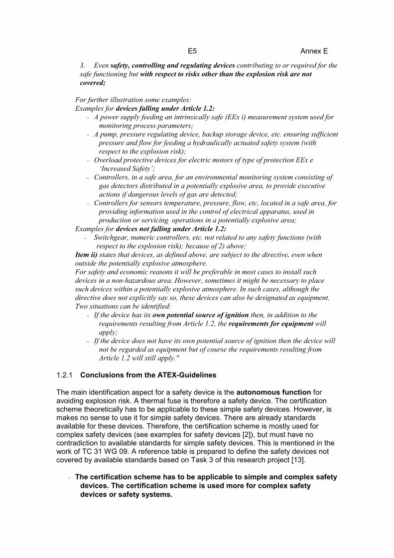
3. Even safety, controlling and regulating devices contributing to or required for thesafe functioning but with respect to risks other than the explosion risk are notcovered;
For further illustration some examples:Examples for devices falling under Article 1.2:
- A power supply feeding an intrinsically safe (EEx i) measurement system used formonitoring process parameters;
- A pump, pressure regulating device, backup storage device, etc. ensuring sufficientpressure and flow for feeding a hydraulically actuated safety system (withrespect to the explosion risk);
- Overload protective devices for electric motors of type of protection EEx e‘Increased Safety’;
- Controllers, in a safe area, for an environmental monitoring system consisting ofgas detectors distributed in a potentially explosive area, to provide executiveactions if dangerous levels of gas are detected;
- Controllers for sensors temperature, pressure, flow, etc, located in a safe area, forproviding information used in the control of electrical apparatus, used inproduction or servicing operations in a potentially explosive area;
Examples for devices not falling under Article 1.2:- Switchgear, numeric controllers, etc. not related to any safety functions (with
respect to the explosion risk); because of 2) above;Item ii) states that devices, as defined above, are subject to the directive, even whenoutside the potentially explosive atmosphere.For safety and economic reasons it will be preferable in most cases to install suchdevices in a non-hazardous area. However, sometimes it might be necessary to placesuch devices within a potentially explosive atmosphere. In such cases, although thedirective does not explicitly say so, these devices can also be designated as equipment.Two situations can be identified:
- If the device has its own potential source of ignition then, in addition to therequirements resulting from Article 1.2, the requirements for equipment willapply;
- If the device does not have its own potential source of ignition then the device willnot be regarded as equipment but of course the requirements resulting fromArticle 1.2 will still apply."
1.2.1 Conclusions from the ATEX-Guidelines
The main identification aspect for a safety device is the autonomous function foravoiding explosion risk. A thermal fuse is therefore a safety device. The certificationscheme theoretically has to be applicable to these simple safety devices. However, ismakes no sense to use it for simple safety devices. There are already standardsavailable for these devices. Therefore, the certification scheme is mostly used forcomplex safety devices (see examples for safety devices [2]), but must have nocontradiction to available standards for simple safety devices. This is mentioned in thework of TC 31 WG 09. A reference table is prepared to define the safety devices notcovered by available standards based on Task 3 of this research project [13].
- The certification scheme has to be applicable to simple and complex safetydevices. The certification scheme is used more for complex safetydevices or safety systems.
E6 Annex E
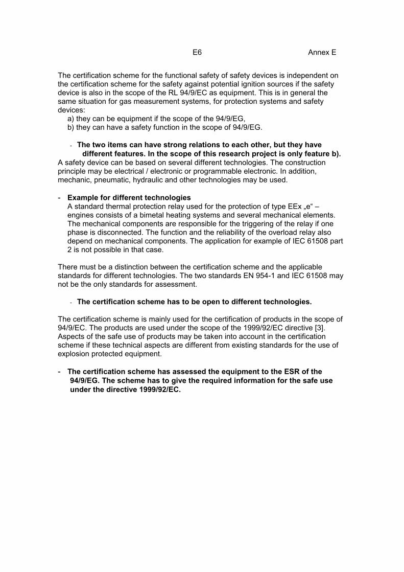
The certification scheme for the functional safety of safety devices is independent onthe certification scheme for the safety against potential ignition sources if the safetydevice is also in the scope of the RL 94/9/EC as equipment. This is in general thesame situation for gas measurement systems, for protection systems and safetydevices:
a) they can be equipment if the scope of the 94/9/EG,b) they can have a safety function in the scope of 94/9/EG.
- The two items can have strong relations to each other, but they havedifferent features. In the scope of this research project is only feature b).
A safety device can be based on several different technologies. The constructionprinciple may be electrical / electronic or programmable electronic. In addition,mechanic, pneumatic, hydraulic and other technologies may be used.
- Example for different technologiesA standard thermal protection relay used for the protection of type EEx „e“ –engines consists of a bimetal heating systems and several mechanical elements.The mechanical components are responsible for the triggering of the relay if onephase is disconnected. The function and the reliability of the overload relay alsodepend on mechanical components. The application for example of IEC 61508 part2 is not possible in that case.
There must be a distinction between the certification scheme and the applicablestandards for different technologies. The two standards EN 954-1 and IEC 61508 maynot be the only standards for assessment.
- The certification scheme has to be open to different technologies.
The certification scheme is mainly used for the certification of products in the scope of94/9/EC. The products are used under the scope of the 1999/92/EC directive [3].Aspects of the safe use of products may be taken into account in the certificationscheme if these technical aspects are different from existing standards for the use ofexplosion protected equipment.
- The certification scheme has assessed the equipment to the ESR of the94/9/EG. The scheme has to give the required information for the safe useunder the directive 1999/92/EC.

E7 Annex E
2 Requirements2.1 Requirements of directives 94/9/EC and 1999/92/EC
The technical requirements (essential safety requirements ESR) of 94/9/EC areincluded in ANNEX II [1]. These requirements are based on existing technicalstandards for explosion protection in group I and group II. The ESR are not fullydescribed in the directive. The authors take the existing standards for explosionprotection into account. Many aspects seem to be open but most times written clearlyin the standards for explosion protection (ANNEX 13 of [2]).
The aspects of using the products are defined in directive 1999/92/EC [3]. It is theinstruction which is the link between the manufacturer and the user. Therefore, theinstructions are given an important role. (ANNEX II of [1]):
"1.0.6. Instructions (a) All equipment and protective systems must be accompanied by instructions,including at least the following particulars:
- a recapitulation of the information with which the equipment or protective system ismarked, except for the serial number (see 1.0.5.), together with any appropriateadditional information to facilitate maintenance (e.g. address of the importer, repairer,etc.);- instructions for safe:
- putting into service,- use,- assembling and dismantling,- maintenance (servicing and emergency repair),- installation,- adjustment;
- where necessary, an indication of the danger areas in front of pressure-relief devices;- where necessary, training instructions;- details which allow a decision to be taken beyond any doubt as to whether an item ofequipment in a specific category or a protective system can be used safely in theintended area under the expected operating conditions;- electrical and pressure parameters, maximum surface temperatures and other limitvalues;- where necessary, special conditions of use, including particulars of possible misusewhich experience has shown might occur;- where necessary, the essential characteristics of tools which may be fitted to theequipment or protective system."
The instruction also is mentioned in the new EN 50014 [15].
With existing standards for explosion protection, therefore products are certified with aview to existing standards for installation, maintenance, repair etc., and the use. Theinformation link between the manufacturer and the user is the instruction.
A certification scheme for safety devices has to assess the required safety.Furthermore the certification scheme has to include all the information for instructionfor safe, etc. ... and special details necessary to decide about the users application.

E8 Annex E
- Example:A safety device is certified that it can be used in an application with SIL 4. In thisspecial application the safety device needs a manual periodic test every day. Itcannot be used normally in explosion protection with standard test rates /maintenance rates. There has to be some information about proof intervals andmaintenance rates if they are different from common used rates.
If this is not possible for the application of the equipment, every parameter fordiagnostics, periodic test etc. has to be defined in the certification under worstconditions and given to the user in the instruction to make sure that the equipment isused in a safe way and the necessary risk reduction is achieved in practical use forevery application.
2.2 Summary of demands from 94/9/EC and 1999/92/EC
The certification for functional safety of safety devices has to assess the safetyrequirements. The certification has to distinguish all relevant parameters for theinstruction given to the user.
3 Selection of concept for certification
Three possible concepts for certification are compared:- A concept independent from technologies and application.- A concept based on a hierarchical structure of standards (A-, B- and C-type
standards).- A concept based on a life cycle structure.
For these different concepts examples are given. The advantages and disadvantagesare pointed out.
3.1 Concept of EN 1441 [9]
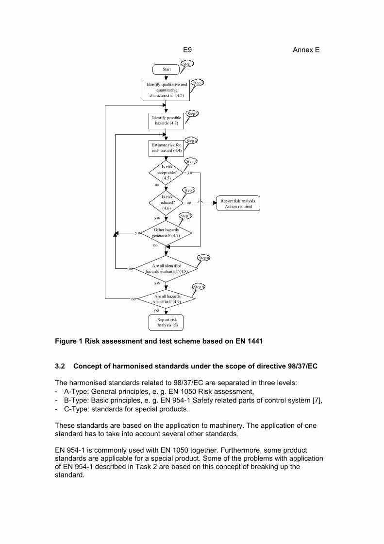
The EN 1441 is based on a basic risk assessment scheme (see Figure 1, an exampletaken from [10]).
The hazards in the steps for example are hardware or software faults or even wronghandling in several situations like manufacturing, transportation, storage and use. Forevery product, all the possible hazards can be identified systematically. Specialapplications can be taken into account. The result is a hazard list for the product. Newproducts have to fulfil this list.
The scheme is open to every application, but the result will be very special to one typeof product. It is an advantage for the use with medical products. The advantage for theapplication to electronic detonators was shown in a CEN working group [10]. A resultwhich is special for one kind of product is the main disadvantage for the application tothe wide range of safety devices.
E9 Annex E
Start
Identify qualitative and quantitative
characteristics (4.2)
Estimate risk for each hazard (4.4)
Is risk acceptable?
(4.5)
Is risk reduced?
(4.6)
Other hazards generated? (4.7)
Are all identified hazards evaluated? (4.8)
Are all hazards identified? (4.9)
Report risk analysis (5)
Report risk analysis. Action required
Identify possible hazards (4.3)
yes
yes
yes
yes
yes
no
no
no
no
no
Step 1
Step 2
Step 3
Step 4
Step 5
Step 6
Step 7
Step 8
Step 9
Figure 1 Risk assessment and test scheme based on EN 1441
3.2 Concept of harmonised standards under the scope of directive 98/37/EC
The harmonised standards related to 98/37/EC are separated in three levels:- A-Type: General principles, e. g. EN 1050 Risk assessment,- B-Type: Basic principles, e. g. EN 954-1 Safety related parts of control system [7],- C-Type: standards for special products.
These standards are based on the application to machinery. The application of onestandard has to take into account several other standards.
EN 954-1 is commonly used with EN 1050 together. Furthermore, some productstandards are applicable for a special product. Some of the problems with applicationof EN 954-1 described in Task 2 are based on this concept of breaking up thestandard.
E10 Annex E
The main advantage of these standards is the application to many technologies; themain disadvantage is that these standards are not applicable to programmablesystems.There is another disadvantage, which should not be missed: the standards are writtenas standards for manufactures. The standards like EN 954 -1 normally give noinformation about installation, maintenance and repair (see Task 2 [11]). The intendeduse of the product is covered by the risk analysis of the manufacturer. Themanufacturers have to give this information for safety use to the user below 98/37/ECas if they have to give it below 94/9/EC. This is not especially written in the standards.The manufactures have to do give all relevant information to the user.
3.3 Concept of IEC 61508
IEC 61508 is the counterpart of several harmonized standards in comparison to theharmonised standards of directive 98/37/EC. The main disadvantage of the standardseems to be the possibility of application only to electric, electronic and programmableelectronic systems. This is wrong. It is possible to distinguish in IEC 61508 two mainparts:
a) The systematic description for the overall life cycle of a system not depending ona specific technology.b) The description of requirements based on safety integrity level (SIL) for electric /electronic / programmable electronic safety-related systems.
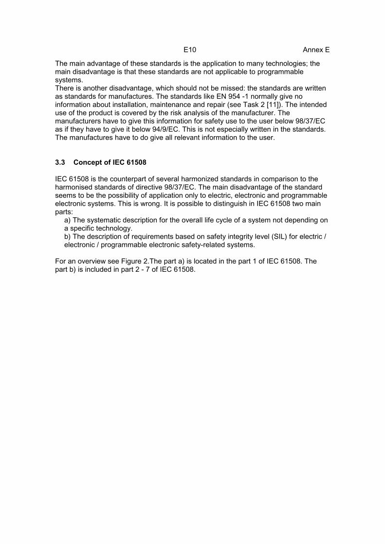
For an overview see Figure 2.The part a) is located in the part 1 of IEC 61508. Thepart b) is included in part 2 - 7 of IEC 61508.
E11 Annex E
Overview of techniques
and measures
PART 7
Guidelines for the application of parts 2 and 3
PART 6
Risk based approaches to the development of
the safety integrity requirements
PART 5
7.6
Realization phase for
safety-related software
PART 3
Realization phase for
E/E/PE safety- related systems
PART 2
Development of the overall safetyrequirements (concept, scope
definition, hazard and risk analysis) (E/E/PE safety-related systems, other
technology safety-related systems and external risk reduction facilities)
7.1 to 7.5
PART 1
Allocation of the safetyrequirements to the E/E/PE
safety-related systems
PART 1
Installation and commissioning and safety validation of E/E/PE
safety-related systems
7.13 and 7.14
PART 1
Operation and maintenance, modification and retrofit,
decommisioning or disposal of E/E/PE safety-related systems
PART 1
7.15 to 7.17
Definitions and abbreviations
PART 4
Management of functional safety
PART 1 Clause 6
Functional safety assessment
PART 1 Clause 8
Documentation
PART 1
Clause 5 and annex A
Other requirements
Technical requirements
Figure 2 Overall framework of the IEC 61508 (IEC 61508 Part 1 Figure 1)
The IEC 61508 describes the whole life cycle of equipment from concept todecommissioning or disposal (see Figure 3).
The validation and certification in general must be open for the application of differenttechnologies and standards (see 1.2.1). This is possible in the life cycle scheme of IEC61508 (see Figure 3). There is a possibility to use other standards. The verificationprocess can take into account the different approaches of the applied standards.

E12 Annex E
10 11
NOTE 1 Activities relating to verification, management of functionalsafety and functional saftey assessment are not shown for reasons of clarity but are relevent to all overall, E/E/PES and software safety lifecycle phases.
NOTE 2 The phases represented by boxes 10 and 11 are outside the scope of this standard.
NOTE 3 Parts 2 and 3 deal with box 9 (realisation) but they also deal, where relevant, with the programmable electronic (hardware and software) aspects of boxes 13, 14 and 15.
1
2
3
4
5
13
Overall modification and retrofit 14 15
16
9 Safety-related systems: E/E/PES
Realization (see E/E/PES
safety lifecycle)
Safety-related systems:
other technology
Realization
Overall safety validation
Overall operation, maintenance and repair
Decommissioning or disposal
Overall installation and commissioning 12
8
Concept
Overall scope definition
Hazard and risk analysis
Overall safety requirements
Safety requirements allocation
Back to appropriate overall safety lifecycle
phase
Overall planning OveralI
operation and maintenance
planning
Overall installation and commissioning
planning
Overall safety
validation planning
6 7 8
External risk reduction facilities
Realization
Figure 3 Overall safety lifecycle (IEC 61508 Part 1 Figure 2)
Every life cycle has a corresponding part in existing explosion protection standards (forexample life cycle 12 and 14: standards for installation and maintenance).
For a certification, the SIL (step 9) and the steps 6, 7 and 8 have to be tested. It has tobe checked whether the life cycles 12 - 14 can be fulfilled under the scope of explosionprotection.
A safety device with other technologies can be certified according to step 10 with otherstandards. A reference table will be necessary, for example, between EN 954-1 levelsand the safety integrity level of IEC 61508. This is not available because thereferences depend on the application and the technology.

E13 Annex E
A problem between IEC 61508 and EN 954-1 is mentioned in Task 2. The safety levelsteps in EN 954-1 are not hierarchically structured. The IEC 61508 and the zonedefinition for explosion protection are linear structured. Furthermore, depending onapplication a safety level in EN 954-1 can lead to different levels in IEC 61508
---
1
B
1
2
3
4
2
3
4
IEC 61508SafetyintegrityLevelSIL
EN 954-1Categorie
?Figure 4 Possible references between IEC 61508 and EN 954
EN 954-1 gives no information about maintenance. The problems defined in Task 2can be handled in step 11 or in step 6. Proof testing can be taken as a risk reductionfacility if the applied standards like EN 954-1 give no information. The other possibilityis to include such problems in step 6, but there the requirements of explosionprotection to operation and maintenance should be placed.
IEC 61508 contains a complete scheme for the handling of a product. This is anadvantage to other possible schemes. In the next chapter, an assignment is madefrom the lifecycle to the area of explosion protection. A complete correlation is possible(see part 3.4).
3.4 Assignment of IEC 61508 lifecycles to the area of explosion protection
The lifecycles of IEC 61508 can be divided into three parts.1. This table contains lifecycles where the preconditions are given by existing
standards for explosion protection (Table 1).2. This table contains the cycles with relation to the certification process (Table 2).3. This table contains the use of the product (Table 3).
To give some information Table 1 of IEC 61508 Part 1 is shown. It is divided into thethree parts. This is mentioned above.

E14 Annex E
Safety lifecyclephaseFigure 3boxnumber
Title
Objectives Scope Requirementssub clause
Inputs Outputs special for safetydevices, examples
1 Concept 7.2.1:To develop a level of understandingof the EUC and its environment(physical, legislative etc) sufficient toenable the other safety lifecycleactivities to be satisfactorily carriedout.
EUC and itsenvironment(physical, legislativeetc).
7.2.2 All relevantinformationnecessary to meetthe requirements ofthe sub clause.
Information acquiredin 7.2.2.1 to 7.2.2.6.
- 94/9/EC- EN 60079-10- existing standards
for explosionprotection: EN50014, ...
2 Overallscopedefinition
7.3.1:To determine the boundary of theEUC and the EUC control system;To specify the scope of the hazardand risk analysis (for exampleprocess hazards, environmentalhazards, etc).
EUC and itsenvironment.
7.3.2 Informationacquired in 7.2.2.1to 7.2.2.6.
Information acquiredin 7.3.2.1 to 7.3.2.5.
- 94/9/EC- EN 60079-10- existing
standards forexplosionprotection: EN50014, ...
3 Hazardand riskanalysis
7.4.1:To determine the hazards andhazardous events of the EUC and theEUC control system (in all modes ofoperation), for all reasonablyforeseeable circumstances includingfault conditions and misuse;To determine the event sequencesleading to the hazardous eventsdetermined;To determine the EUC risksassociated with the hazardous eventsdetermined.
The scope will bedependent upon thephase reached inthe overall,E/E/PES andsoftware safetylifecycles (since itmay be necessaryfor more than onehazard and riskanalysis to becarried out). For thepreliminary hazardand risk analysis,the scope willcomprise the EUC,the EUC controlsystem and humanfactors.
7.4.2 Informationacquired in 7.3.2.1to 7.3.2.5.
Description of, andinformation relatingto, the hazard andrisk analysis.
- 94/9/EC- existing standards
for explosionprotection: EN50014, ...

E15 Annex ESafety lifecyclephaseFigure 3boxnumber
Title
Objectives Scope Requirementssub clause
Inputs Outputs special for safetydevices, examples
4 Overallsafetyrequire-ments
7.5.1:To develop the specification for theoverall safety requirements, in termsof the safety functions requirementsand safety integrity requirements, forthe E/E/PE safety-related systems,other technology safety-relatedsystems and external risk reductionfacilities, in order to achieve therequired functional safety.
EUC, the EUCcontrol system andhuman factors.
7.5.2 Description of, andinformation relatingto, the hazard andrisk analysis.
Specification for theoverall safetyrequirements in termsof the safetyfunctionsrequirements and thesafety integrityrequirements.
- 94/9/EC- existing standards
for explosionprotection: EN50014, ...
- Task 1[11]- Task 2 [11]
5 Safetyrequire-mentsallocation
7.6.1:To allocate the safety functions,contained in the specification for theoverall safety requirements (both thesafety functions requirements and thesafety integrity requirements), to thedesignated E/E/PE safety-relatedsystems, other technology safety-related systems and external riskreduction facilities;To allocate a safety integrity level toeach safety function.
EUC, the EUCcontrol system andhuman factors.
7.6.2 Specification for theoverall safetyrequirements interms of the safetyfunctionsrequirements andthe safety integrityrequirements.
Information andresults of the safetyrequirementsallocation.
- existing standardsfor explosionprotection: EN50 014, ...
- Task 1[11]- Task 2 [11]
Table 1- Overall safety lifecycle: overview - correlation to explosion protection (IEC 61508 Part 1 Table 1) - preconditions givenby existing standards
E16 Annex E
Safety lifecycle phaseFigure 2boxnumber
TitleObjectives Scope Requirements
sub clauseInputs Outputs Special for safety
devices, examples
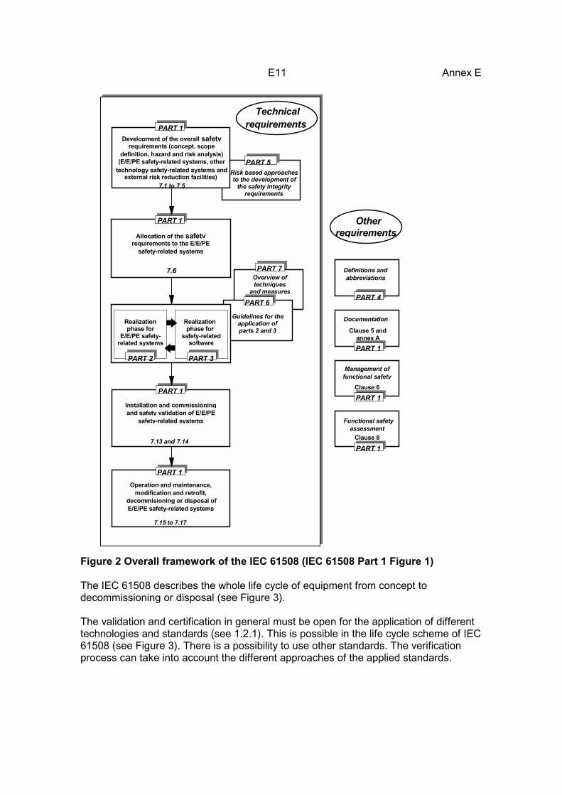
6 Overalloperationandmaintenanceplanning
7.7.1:To develop a plan for operatingand maintaining the E/E/PEsafety-related systems, toensure that the requiredfunctional safety is maintainedduring operation andmaintenance.
EUC, the EUCcontrol system andhuman factors;E/E/PE safety-related systems.
7.7.2 Specification for theoverall safetyrequirements in termsof the safetyfunctionsrequirements and thesafety integrityrequirements.
A plan for operatingand maintaining theE/E/PE safety-relatedsystems.
- 94/9/EC AnnexII, 1.0.6Instructions
- EN 60079-14[18]
- EN 60 079-17[20]
7 Overallsafetyvalidationplanning
7.8.1:To develop a plan to facilitatethe overall safety validation ofthe E/E/PE safety-relatedsystems.
EUC, the EUCcontrol system andhuman factors;E/E/PE safety-related systems.
7.8.2 Specification for theoverall safetyrequirements in termsof the safetyfunctionsrequirements and thesafety integrityrequirements.
A plan to facilitate thevalidation of theE/E/PE safety-relatedsystems.
- 94/ 9/EGAnnex II, 1.0.6Instructions
- EN 60079-14[18]
8 Overallinstallationandcommission-ing planning
7.9.1:To develop a plan for theinstallation of the E/E/PE safety-related systems in a controlledmanner, to ensure the requiredfunctional safety is achieved;To develop a plan for thecommissioning of the E/E/PEsafety-related systems in acontrolled manner, to ensure therequired functional safety isachieved.
EUC and the EUCcontrol system;E/E/PE safety-related systems.
7.9.2 Specification for theoverall safetyrequirements in termsof the safetyfunctionsrequirements and thesafety integrityrequirements.
A plan for theinstallation of theE/E/PE safety-relatedsystems;A plan for thecommissioning of theE/E/PE safety-relatedsystems.
- 94/ 9/EGAnnex II, 1.0.6Instructions
- EN 60 079-14- EN 50281-1-2

E17 Annex ESafety lifecycle phaseFigure 2boxnumber
TitleObjectives Scope Requirements
sub clauseInputs Outputs Special for safety
devices, examples
9 E/E/PEsafety-relatedsystems:realization
7.10.1 and parts 2 and 3:To create E/E/PE safety-relatedsystems conforming to thespecification for the E/E/PESsafety requirements (comprisingthe specification for the E/E/PESsafety functions requirementsand the specification for theE/E/PES safety integrityrequirements).
E/E/PE safety-related systems.
7.10.2 andparts 2 and 3
Specification for theE/E/PES safetyrequirements.
Confirmation that eachE/E/PE safety-relatedsystem meets theE/E/PES safetyrequirementsspecification.
- 94/9/EC AnnexII
- IEC 61508 Part2 and 3
10 Othertechnologysafety-relatedsystems:realisation
7.11.1:To create other technologysafety-related systems to meetthe safety functionsrequirements and safety integrityrequirements specified for suchsystems (outside the scope ofthis standard).
Other technologysafety-relatedsystems.
7.11.2 Other technologysafety requirementsspecification (outsidethe scope and notconsidered further inthis standard).
Confirmation that eachother technologysafety-related systemsmeets the safetyrequirements for thatsystem.
- 94/9/EG AnnexII
- EN 954 Part 1and 2
11 External riskreductionfacilities:realization
7.12.1:To create external risk reductionfacilities to meet the safetyfunctions requirements andsafety integrity requirementsspecified for such facilities(outside the scope of thisstandard).
External riskreduction facilities.
7.12.2 External riskreduction facilitiessafety requirementsspecification(outside the scopeand not consideredfurther in thisstandard).
Confirmation that eachexternal risk reductionfacility meets the safetyrequirements for thatfacility.
- 1999/92/EC- Special pro-
cedures
Table 2- Overall safety lifecycle: overview - correlation to explosion protection (IEC 61508 Part 1 Table 1) - lifecycles in relationto certification process
E18 Annex ESafety lifecyclephaseFigure 2boxnumber
Title
Objectives Scope Requirementssub clause
Inputs Outputs special forsafety devices,examples
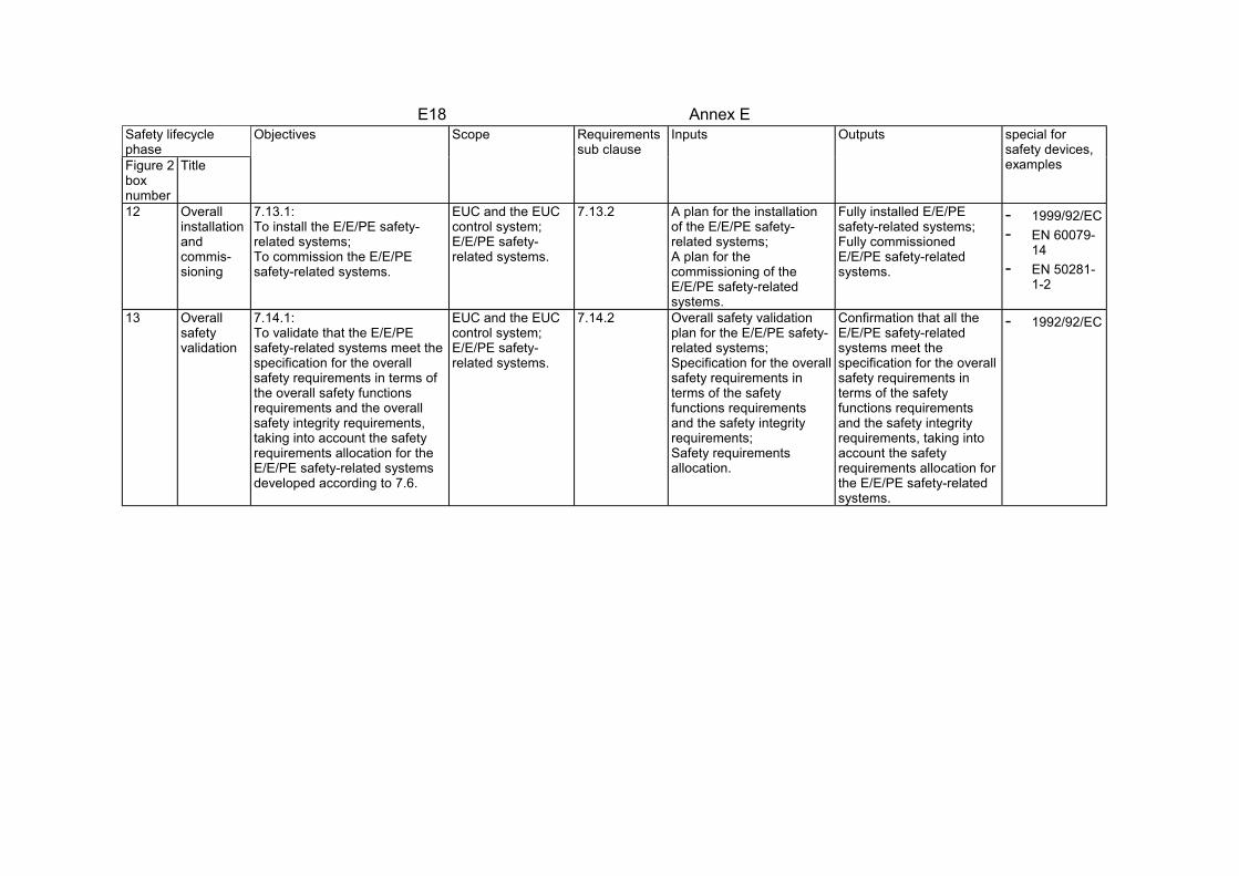
12 Overallinstallationandcommis-sioning
7.13.1:To install the E/E/PE safety-related systems;To commission the E/E/PEsafety-related systems.
EUC and the EUCcontrol system;E/E/PE safety-related systems.
7.13.2 A plan for the installationof the E/E/PE safety-related systems;A plan for thecommissioning of theE/E/PE safety-relatedsystems.
Fully installed E/E/PEsafety-related systems;Fully commissionedE/E/PE safety-relatedsystems.
- 1999/92/EC- EN 60079-
14- EN 50281-
1-2
13 Overallsafetyvalidation
7.14.1:To validate that the E/E/PEsafety-related systems meet thespecification for the overallsafety requirements in terms ofthe overall safety functionsrequirements and the overallsafety integrity requirements,taking into account the safetyrequirements allocation for theE/E/PE safety-related systemsdeveloped according to 7.6.
EUC and the EUCcontrol system;E/E/PE safety-related systems.
7.14.2 Overall safety validationplan for the E/E/PE safety-related systems;Specification for the overallsafety requirements interms of the safetyfunctions requirementsand the safety integrityrequirements;Safety requirementsallocation.
Confirmation that all theE/E/PE safety-relatedsystems meet thespecification for the overallsafety requirements interms of the safetyfunctions requirementsand the safety integrityrequirements, taking intoaccount the safetyrequirements allocation forthe E/E/PE safety-relatedsystems.
- 1992/92/EC

E19 Annex ESafety lifecyclephaseFigure 2boxnumber
Title
Objectives Scope Requirementssub clause
Inputs Outputs special forsafety devices,examples
14 Overalloperation,maintenance andrepair
7.15.1:To operate, maintain and repairthe E/E/PE safety-relatedsystems in order that therequired functional safety ismaintained.
EUC and the EUCcontrol system;E/E/PE safety-related systems.
7.15.2 Overall operation andmaintenance plan for theE/E/PE safety-relatedsystems.
Continuing achievement ofthe required functionalsafety for the E/E/PEsafety-related systems;Chronologicaldocumentation ofoperation, repair andmaintenance of the E/E/PEsafety-related systems.
- 94/9/ECAnnex II,1.0.3Specialcheckingandmaintenanceconditions,1.0.6Instructions
- 1992/92/EC- EN 60079-
14- EN 60079-
17- prEN
60079-1915 Overall
modification andretrofit
7.16.1:To ensure that the functionalsafety for the E/E/PEsafety-related systems isappropriate, both during andafter the modification and retrofitphase has taken place.
EUC and the EUCcontrol system;E/E/PE safety-related systems.
7.16.2 Request for modification orretrofit under theprocedures for themanagement of functionalsafety.
Achievement of therequired functional safetyfor the E/E/PE safety-related systems, bothduring and after themodification and retrofitphase has taken place;Chronologicaldocumentation ofoperation, repair andmaintenance of the E/E/PEsafety-related systems.
- 94/9/ECAnnex II
- 1999/92/EC- EN 60 079-
14- EN 50281-
1-2

E20 Annex ESafety lifecyclephaseFigure 2boxnumber
Title
Objectives Scope Requirementssub clause
Inputs Outputs special forsafety devices,examples
16 Decommissioning ordisposal
7.17.1:To ensure that the functionalsafety for the E/E/PE safety-related systems is appropriatein the circumstances during andafter the activities ofdecommissioning or disposingof the EUC.
EUC and the EUCcontrol system;E/E/PE safety-related systems.
7.17.2 Request fordecommissioning ordisposal under theprocedures for themanagement of functionalsafety.
Achievement of therequired functional safetyfor the E/E/PE safety-related systems bothduring and after thedecommissioning ordisposal activities;Chronologicaldocumentation of thedecommissioning ordisposal activities.
-
Table 3 - Overall safety lifecycle: overview - correlation to explosion protection (IEC 61508 Part 1 Table 1) - lifecycles regardingto the use of products

E21 Annex E
3.4.1 Conclusion for IEC 61508
IEC 61508 is applicable for the certification of safety devices under the scope of the94/9/EC [1]. The approach of IEC 61508 covers the scope of 94/9/EC and 1999/92/EC.IEC 61508 allows the use of not explicitly mentioned technologies for validation. TheESR can be covered by validation following IEC 61508.
There may be some differences for instance if a thermal control device is used for thecontrol of electrical equipment or for the protection of non-electrical equipmentbecause in 94/9/EC the certification procedure is different.
3.5 Summary
Every concept has advantages and disadvantages. With the use of EN 1441 or EN954-1 many things have to be added to get a certification scheme for safety devices inthe area of explosion protection.
IEC 61508 gives a complete concept for the certification of safety devices. Thedisadvantage is application only for specific technologies. The concept on the otherhand is open for use of standards with other technologies. IEC 61508 only has toadapt to the use with safety devices for explosion protection.
4 Conformity assessment procedure according to IEC 615084.1 Conditions
For a conformity assessment procedure based on IEC 61508 minor changes have tobe made for the application to safety devices.
- The boxes 1 - 4 are already fulfilled by existing standards for explosion protectionand the work in Task 1 and Task 2 [11].
- The box 5 is mainly defined by existing standards for explosion protection (function)and Task 2 (safety integrity level).
The safety integrity level for a purge control system is defined. Even the safety integritylevel for a thermal protection system can easily be defined.For example, a type “e” engine is not suitable for zone 1 without a thermal protectionsystem. So this safety device is needed. It has to be added and the safety function“thermal protection” has to fulfil SIL 2.In other cases, the manufacturer and the notified body have to do the safetyrequirement allocation according to IEC 61508, Part 1, 7.6.

E22 Annex E
4.2 Validation process
- The certification scheme itself bases on the box 9, Figure 3 for electric / electronicor programmable electronic safety devices or on box 10, Figure 3 together with box11 for other technologies.
Figure 5 and Figure 6 shows lifecycle realization phase including validation process.
- The notified bodies have to carry out the conformity assessment procedureaccording to boxes 9.1 to 9.6 for hardware and software. The assessment caninclude less or more the point 9.1 to 9.5. This is depending on the safety devices.The most important step is 9.6.
Safety-related systems: E/E/PES
Realization
9
Box 9 in figure 2
9.1
9.1.1 9.1.2Safety functionsrequirementsspecification
Safety integrity requirementsspecification
E/E/PES safety requirementsspecification
To box 12 in figure
E/E/PES safetyvalidation
9.6
E/E/PES safetyvalidation planning
E/E/PES design and development
9.39.2
9.4 E/E/PES operation and maintenance procedures
9.5E/E/PES integration
One E/E/PES safetylifecycle for each
E/E/PE safety-relatedsystem
To box 14 in figure 2
E/E/PES safety lifecycle
Figure 5 E/E/PES safety lifecycle (in realization phase)(IEC 61508 part 1, figure 3)
E23 Annex E
9.6
Safety functionsrequirementsspecification
Safety integrityrequirementsspecification
9.1
9.1.1 9.1.2
Software safety requirementsspecification
To box 12 in figure 2
9.39.2
9.4 9.5
Software safetyvalidation
Software safetyvalidation planning
Software designand development
Software operation andmodification procedures
PE integration(hardware/software)
To box 14in figure 2
E/E/PESsafety
lifecycle(see figure 3)
Software safety lifecycle
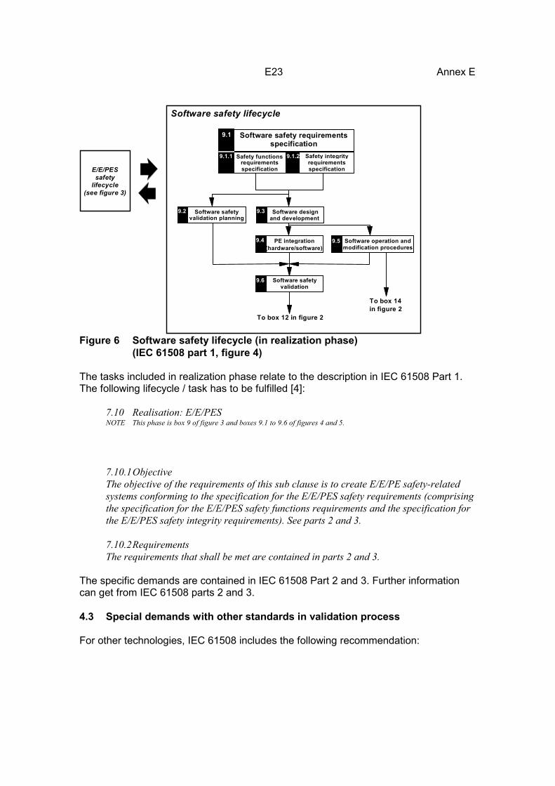
Figure 6 Software safety lifecycle (in realization phase)(IEC 61508 part 1, figure 4)
The tasks included in realization phase relate to the description in IEC 61508 Part 1.The following lifecycle / task has to be fulfilled [4]:
7.10 Realisation: E/E/PESNOTE This phase is box 9 of figure 3 and boxes 9.1 to 9.6 of figures 4 and 5.
7.10.1ObjectiveThe objective of the requirements of this sub clause is to create E/E/PE safety-relatedsystems conforming to the specification for the E/E/PES safety requirements (comprisingthe specification for the E/E/PES safety functions requirements and the specification forthe E/E/PES safety integrity requirements). See parts 2 and 3.
7.10.2RequirementsThe requirements that shall be met are contained in parts 2 and 3.
The specific demands are contained in IEC 61508 Part 2 and 3. Further informationcan get from IEC 61508 parts 2 and 3.
4.3 Special demands with other standards in validation process
For other technologies, IEC 61508 includes the following recommendation:

E24 Annex E
7.11 Realization: other technologyNOTE: This phase is box 10 of figure 3.
7.11.1ObjectiveThe objective of the requirements of this sub clause is to create other technology safety-related systems to meet the safety functions requirements and safety integrityrequirements specified for such systems.
7.11.2RequirementsThe specification to meet the safety functions requirements and safety integrityrequirements for other technology safety-related systems is not covered in this standard.NOTE: Other technology safety-related systems are based on a technology other than electrical/electronic/programmableelectronic (for example hydraulic, pneumatic etc). The other technology safety-related systems have been included in theoverall safety lifecycle, together with the external risk reduction facilities, for completeness (see 7.12).
The validation for other technologies can be led by using EN 954-1. Specification ofthe validation process is urgent necessary (see Task 2). PrEN 954-2 e.g. can be used.Other standards are possible (for example DIN EN 61496-1 06/98).
The lack of information e.g. about proof intervals has to be covered by specialprocedures. The validation of a electrical / electronic or programmable electronicdevices with the EN 954-1 needs separate calculation of reliability for circuitsresponsible for the validated safety function.
This additional validation may be allocated to the lifecycles Overall safety validationplanning (box 6, Figure 3) or to External risk reduction facilities (box 11, Figure 3).IEC 61508 part 1, Chapter 7.12 give some further information.
7.12 Realisation: external risk reduction facilitiesNOTE: This phase is box 11 of figure 3.
7.12.1ObjectiveThe objective of the requirements of this sub clause is to create external risk reductionfacilities to meet the safety functions requirements and safety integrity requirementsspecified for such facilities.
7.12.2RequirementsThe specification to meet the safety functions requirements and safety integrityrequirements for the external risk reduction facilities is not covered in this standard.NOTE The external risk reduction facilities have been included in the overall safety lifecycle, together with the othertechnology safety-related systems for completeness (see 7.11).
4.4 Special information for instruction
Furthermore, the notified bodies have to proof the results of the E 7 E / PES safetyvalidation (lifecycle 9.6). The overall planning (lifecycles shown in box 6 - 8 (Figure 3))has to proof according to the directive 1999/92 and the existing standards if specialinformation must given in the instruction for the use of safety devices.
E25 Annex E
4.5 Actual problems with IEC 61508
A problem for application of IEC 61508 – 2 is that the standard is only available a draftand the whole IEC 61508 is not harmonised. The EN 954-1 is available as aharmonised standard. Therefore, standardisation committees for example in the typeEEx “p” standard refer to EN 954-1 for validation. Even the committee for gasmeasurement systems do this.The IEC 61508 needs for application a reliable database. There are several databasesin use (Task 2, Task 4). Today no common database exists. Like in other standards forexplosion protection, this common database must be established before certificationcan bases on IEC 61508 alone.
The authors do certification for some pressurized system controller according EN 954-1. The systems were suitable for application in category 3. Category 3 wasrecommend in an earlier draft for pressurised systems.
The controllers were also validated applying IEC 61508 - 2. Special attention was givento the dangerous undetected faults. The probability for dangerous undetected faultswas calculated to give special information in the instruction if necessary. Twodatabases had been used ([22], [23]). The probability for failure in low demand modeof operation was low enough to fulfill safety integrity level 3. Because of a lack forproof testing the controllers are only suitable for a SIL 2 application (because ofarchitectural constraints 61508 – 2, 7.4.5). This is the recommended SIL forpressurised system controller in Task 2. The result from EN 954-1 and IEC 61508 fitsin this special application.
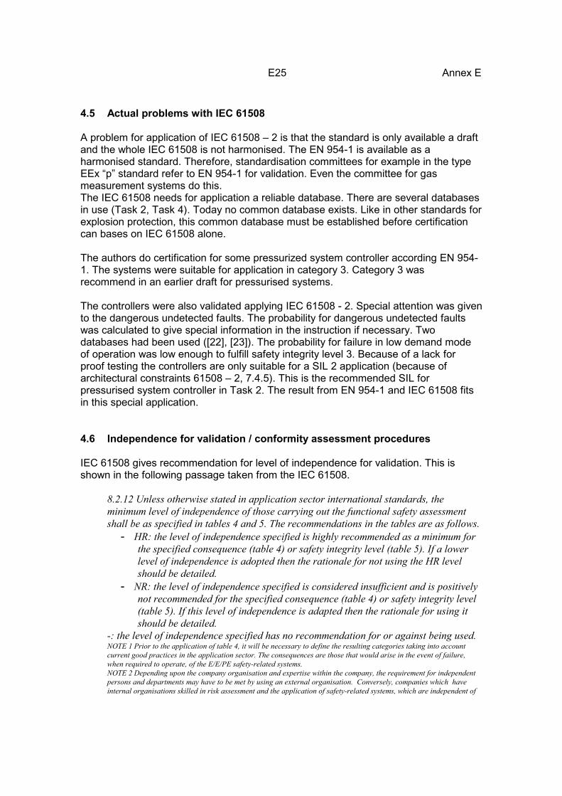
4.6 Independence for validation / conformity assessment procedures
IEC 61508 gives recommendation for level of independence for validation. This isshown in the following passage taken from the IEC 61508.
8.2.12 Unless otherwise stated in application sector international standards, theminimum level of independence of those carrying out the functional safety assessmentshall be as specified in tables 4 and 5. The recommendations in the tables are as follows.
- HR: the level of independence specified is highly recommended as a minimum forthe specified consequence (table 4) or safety integrity level (table 5). If a lowerlevel of independence is adopted then the rationale for not using the HR levelshould be detailed.
- NR: the level of independence specified is considered insufficient and is positivelynot recommended for the specified consequence (table 4) or safety integrity level(table 5). If this level of independence is adapted then the rationale for using itshould be detailed.
-: the level of independence specified has no recommendation for or against being used.NOTE 1 Prior to the application of table 4, it will be necessary to define the resulting categories taking into accountcurrent good practices in the application sector. The consequences are those that would arise in the event of failure,when required to operate, of the E/E/PE safety-related systems.NOTE 2 Depending upon the company organisation and expertise within the company, the requirement for independentpersons and departments may have to be met by using an external organisation. Conversely, companies which haveinternal organisations skilled in risk assessment and the application of safety-related systems, which are independent of

E26 Annex E
and separate (by ways of management and other resources) from those responsible for the main development, may beable to use their own resources to meet the requirements for an independent organization.NOTE 3 See 3.8.10, 3.8.11 and 3.8.12 of part 4 for definitions of independent person, independent department andindependent organisation respectively.
8.2.13 In the context of tables 4 and 5, either HR1 or HR2 is applicable (not both),depending on a number of factors specific to the application. If HR1 is applicable thenHR2 should be read as no requirement; if HR2 is applicable then HR1 should be read asNR (not recommended). If no application sector standard exists, the rationale forchoosing HR1 or HR2 should be detailed. Factors that will tend to make HR2 moreappropriate than HR1 are:
- lack of previous experience with a similar design;- greater degree of complexity;- greater degree of novelty of design;- greater degree of novelty of technology;- lack of degree of standardisation of design features.
8.2.14 In the context of table 4, the minimum levels of independence shall be based onthe safety function, carried out by the E/E/PE safety-related system, that has the highestsafety integrity level.
Safety integrity levelMinimum level of Independence1 2 3 4
Independent person HR HR1 NR NRIndependent department - HR2 HR1 NRIndependent organization (see note 2 of8.2.12)
- - HR2 HR
NOTE See 8.2.12 (including notes), 8.2.13 and 8.2.14 for details on interpreting thistable.
Table 4 - Minimum levels of independence of those carrying out functional safetyassessment (overall safety lifecycle phase 9 - includes all phases ofE/E/PES and software safety lifecycles (see Figure 3, Figure 5 andFigure 6))
IEC 61508 is not written to a special scope of application. The tables given by IEC61508 part 1 have to change in respect to the regulations of 94/9/EC CHAPTER IIConformity assessment procedures, Article 8. Under the scope of the directive94/9/EC, the table have to be divided into two parts, because the certification ofelectrical and non-electrical equipment is different ([1], Chapter II, Article 8)
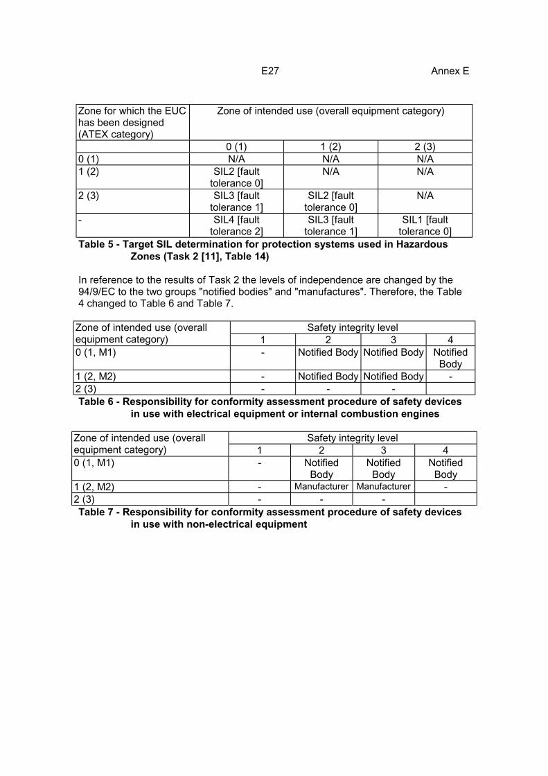
E27 Annex E
Zone for which the EUChas been designed(ATEX category)
Zone of intended use (overall equipment category)
0 (1) 1 (2) 2 (3)0 (1) N/A N/A N/A1 (2) SIL2 [fault
tolerance 0]N/A N/A
2 (3) SIL3 [faulttolerance 1]
SIL2 [faulttolerance 0]
N/A
- SIL4 [faulttolerance 2]
SIL3 [faulttolerance 1]
SIL1 [faulttolerance 0]
Table 5 - Target SIL determination for protection systems used in HazardousZones (Task 2 [11], Table 14)
In reference to the results of Task 2 the levels of independence are changed by the94/9/EC to the two groups "notified bodies" and "manufactures". Therefore, the Table4 changed to Table 6 and Table 7.
Safety integrity levelZone of intended use (overallequipment category) 1 2 3 40 (1, M1) - Notified Body Notified Body Notified
Body1 (2, M2) - Notified Body Notified Body -2 (3) - - -Table 6 - Responsibility for conformity assessment procedure of safety devices
in use with electrical equipment or internal combustion engines
Safety integrity levelZone of intended use (overallequipment category) 1 2 3 40 (1, M1) - Notified
BodyNotified
BodyNotified
Body1 (2, M2) - Manufacturer Manufacturer -2 (3) - - -Table 7 - Responsibility for conformity assessment procedure of safety devices
in use with non-electrical equipment

E28 Annex E
5 Summary
For the conformity assessment procedure, several standards are available. The mostgeneral standard is the IEC 61508. Because there is a large number of very differentsafety devices identified in Task 3 [13] it is important to take a general standard. Thisshould be the IEC 61508, because this standards covers although the production andthe use of electrical / electronic / programmable electronic systems. This is animportant fact because for safety devices the two areas defined by the directives94/9/EC [1] and 1999/92/EC [3] cannot be separated.
The IEC 61508 is open for the use of other standards for the validation of safetydevices. This is even an important fact. For example, the EN 50 016 [16] recommendsthe use of the EN 954-1 for the validation of the used safety devices. This is done evenin other standards or drafts [24].
The IEC 61508 can be regarded as a standard for the basic procedure and as "genericstandard" for safety devices. In some cases "products standards" can be used if theyare recommended from the specific standardisation committee. This is nearly the sameprinciple like in the directive 89/336/EC for electromagnetic compatibility (“genericstandards” 50082-xx together with test standards IEC 61000-4-xx and “productstandards” with test standards IEC 61000-4-xx).
Common database is urgently needed (reliability of used components) for applicationof IEC 61508-2 in certification of safety devices. Without such a data base acertification in the scope of 94/9/EG in an equal safety level in different Europeancountries cannot be achieved.
Furthermore today certification of safety devices is only possible according toharmonized standards like EN 954-1 or according to the directive 94/9/EC itself.
E29 Annex E
6 References
[1] Directive 94/9/EC of the European Parliament and the Council of 23 March 1994on the approximation of the laws of the Member States concerning equipmentand protective systems intended for use in potentially explosive atmospheres,394L0009
[2] ATEX Guidelines - Guidelines on the Application of Council Directive 94/9/EC of23 March 1994 on the Approximation of the Laws of the Member Statesconcerning Equipment and Protective Systems intended for Use in potentiallyexplosive Atmospheres, Draft 3 February 1999
[3] Directive 1999/92/EC of the European Parliament and of the Council of 16December 1999 on minimum requirements for improving the safety and healthprotection of workers potentially at risk from explosive atmospheres (15thindividual Directive within the meaning of Article 16(1) of Directive 89/391/EEC)
[4] IEC 61508 Functional safety of electrical/electronic/ programmable electronicsafety-related systems - Part 1: General requirements, 1998-12
[5] Draft IEC 61508 Functional safety of electrical/electronic/programmableelectronic safety-related systems - Part 2: Requirements forelectrical/electronic/programmable electronic safety-related systems
[6] IEC 61508 Functional safety of electrical/electronic/programmable electronicsafety-related systems - Part 3: Software requirements, 1998-12
[7] EN 954-1: 1997, Safety of machinery - Safety-related parts of control systems -Part 1. General principles for design
[8] prEN 954-2:1998, Safety of machinery - Safety-related parts of control systems -Part 2: Validation
[9] EN 1441:1997 Medical devices - Risk analysis[10] Draft EN xxxxx Explosives for civil uses - Detonators and relays , Part 27
Definitions, methods and requirements for electronic initiation systems[11] Determination of safety categories of electrical devices used in potentially
explosive atmospheres: Report on Task 1: Derivation of Target Failure Measures[12] Determination of safety categories of electrical devices used in potentially
explosive atmospheres: Report on Task 2: Assessment of Current ControlSystem Standards, SAFEC project, Contract SMT4-CT98-2255, A. M. Wray,Engineering Control Group, Health & Safety Executive, 01/2000
[13] Determination of safety categories of Electrical devices used in PotentiallyExplosive Atmospheres: Report on Task 3:, Identification of “Used SafetyDevices”, SAFEC project, Contract SMT4-CT98-2255, E. Conde,LABORATORIO OFICIAL MADARIAGA (LOM), November 1999
[14] Determination of safety categories of Electrical devices used in PotentiallyExplosive Atmospheres: Report on Task 4:, Study of “Used Safety Devices”,SAFEC project, Contract SMT4-CT98-2255, E. Faé, S. Halama, Institut NationalDe L'Environnement Industriel Et Des Risques (INERIS), November 1999

E30 Annex E
[15] EN 50014:1999 Electrical apparatus for potentially explosive atmospheres -General requirements
[16] EN 50016:1995 Electrical apparatus for potentially explosive atmospheres -Pressurised apparatus "p"
[17] EN 50281-1-2:1999 Electrical apparatus for use in the presence of combustibledust - Part 1-2: Electrical apparatus protected by enclosure - Selection,installation and maintenance
[18] EN 60079-10:1996 Electrical apparatus for explosive atmospheres - Part 10:Classification of hazardous areas
[19] EN 60079-14:1997 Electrical apparatus for potentially explosive atmospheres -Electrical installations in hazardous areas (other than mines)
[20] EN 60079-17:1997 Electrical apparatus for potentially explosive atmospheres -Inspection and maintenance of electrical installations in hazardous areas (otherthan mines)
[21] prEN60079-19:1992 Installation of electrical apparatus in hazardous areas;Repair and overhaul for apparatus used in explosive atmospheres (other thanmines)
[22] SN 29000 Teil 1 - 14, Ausfallraten Bauelemente, Erwartungswerte, Allgemeines,Siemens AG, 11.1991
[23] Reliability, Maintainability and Risk, Practical methods for engineers, David J.Smith, Butterworth Heinemann, Fifth Edition
[24] Electrical apparatus for the detection and measurement of combustible or toxicgases or vapours or of oxygen; Requirements on the functional safety of fixedgas detection systems, First draft, 15.12.1999
[25] TC31-WG9, CENELEC, Electrical equipment for potentially explosiveatmospheres, Reliability of safety-related devices, 1. Draft proposal 1999-xx-yy,12/02/1999.