Task 2: Beam Angles and Directional Lamps - Defra,...
26
Task 2: Beam Angles and Directional Lamps A report prepared in support of the European Commission’s work evaluating Directional Lamps under the Energy Using Products Directive. A report prepared by: Navigant Consulting Europe, Ltd. May 2010
Transcript of Task 2: Beam Angles and Directional Lamps - Defra,...

Task 2: Beam Angles and Directional Lamps A report prepared in support of the European Commission’s work evaluating Directional Lamps under the Energy Using Products Directive. A report prepared by: Navigant Consulting Europe, Ltd.
May 2010

Task 2 - Beam Angles and Directional Lamps
ii
Published by the Department for Environment, Food and Rural Affairs Department for Environment, Food and Rural Affairs Nobel House 17 Smith Square London SW1P 3JR Tel: 020 7238 6000 Website: www.defra.gov.uk © Queen's Printer and Controller of HMSO 2010 This publication is value added. If you wish to re-use this material, please apply for a Click-Use Licence for value added material at: http://www.opsi.gov.uk/click-use/value-added-licence-information/index.htm Alternatively applications can be sent to Office of Public Sector Information, Information Policy Team, St Clements House, 2-16 Colegate, Norwich NR3 1BQ; Fax: +44 (0)1603 723000; email: [email protected] Information about this publication is available from: SCP&W Evidence Base Defra Zone 5D, 5th Floor, Ergon House c/o Nobel House, 17 Smith Square London SW1P 3JR Email: [email protected] This report was prepared by Navigant1 Consulting Europe, Ltd. for the UK Department for Environment, Food and Rural Affairs (Defra), the Swedish Energy Agency and the European Council for an Energy Efficient Economy (eceee), who supported this effort. The views expressed reflect the research findings and interpretation of Navigant Consulting Europe, and do not necessarily reflect the policy or opinions of Defra, the Swedish Energy Agency or eceee. This report represents Navigant Consulting Europe’s best efforts and judgments based on the information available at the time this report was prepared. Navigant Consulting Europe is not responsible for the reader’s use of, or reliance upon, the report, nor any decisions based on the report. NAVIGANT CONSULTING EUROPE MAKES NO REPRESENTATIONS OR WARRANTIES, EXPRESSED OR IMPLIED. Readers of the report are advised that they assume all liabilities incurred by them, or third parties, as a result of their reliance on the report, or the data, information, findings and opinions contained in the report. Navigant Consulting (Europe) Limited Attn: Michael Scholand Woolgate Exchange, 5th Floor 25 Basinghall Street London, EC2V 5HA Tel: +44 (0)207 469 1111 Fax: +44 (0)207 469 1110 www.navigantconsulting.com
1 “Navigant” is a service mark of Navigant International, Inc. Navigant Consulting Europe, Ltd., a wholly owned subsidiary of Navigant Consulting, Inc. (NCI) is not affiliated, associated, or in any way connected with Navigant International, Inc. and NCI’s use of “Navigant” is made under license from Navigant International, Inc.

Task 2 - Beam Angles and Directional Lamps
3
TABLE OF CONTENTS
1 Introduction ...................................................................................................... 5
1.1 Context .................................................................................................................................... 5
1.2 Overview of this Report ........................................................................................................... 5
2 Background and EuP Preparatory Study ....................................................... 7
2.1 Key concepts and definitions .................................................................................................. 7
2.2 Reflective Surfaces ................................................................................................................. 8
2.3 EuP Preparatory Study ......................................................................................................... 10
3 Critical Review ................................................................................................ 13
3.1 Pmax Correction Factors for Certain Lamp Types .................................................................. 13
3.2 Correction Factors for Discrete Cones of Light ..................................................................... 15
3.3 Other Regulatory Organisations............................................................................................ 19
3.4 Comparison of Efficacy Requirements .................................................................................. 19
4 Conclusions .................................................................................................... 23
References .............................................................................................................. 24
LIST OF TABLES
TABLE 1-1. REPORT OUTLINE AND DESCRIPTIONS OF THE SUBSTANTIVE CHAPTERS ............................................. 6
TABLE 2-1. ELC BEAM WIDTH CATEGORY PROPOSAL TO THE COMMISSION ........................................................ 11
TABLE 2-2. SAMPLE OF LAMPS IDENTIFIED IN THE EUP PREPARATORY STUDY .................................................... 12
TABLE 3-1. PROPOSED CORRECTION FACTORS FOR CERTAIN LAMP TYPES .......................................................... 14
TABLE 3-2. CCT VARIANCE IN LUMINOUS EFFICACY REQUIREMENTS FOR ELI ................................................... 14
TABLE 3-3. CONES ANGLES AND ADJUSTMENT FACTORS BY LAMP TYPE ............................................................. 16
TABLE 3-4. REGULATION FOR NON-DIRECTIONAL LIGHT SOURCES, EC 244/2009 ............................................... 18
TABLE 3-5. EUP PREPARATORY STUDY LEVEL: BAT WITH LOCK-IN EFFECT ....................................................... 19
TABLE 3-6. NEW LAMP EFFICACY LEVELS USED IN PART 2 OF EUP PREPARATORY STUDY ................................. 20
LIST OF FIGURES
FIGURE 2-1. GRAPHIC LABELLING ANGLES DESCRIBING DIRECTIONAL LAMP LIGHT EMISSION ............................ 7
FIGURE 2-2. GRAPHIC INDICATING LOCATION OF REFLECTIVE SURFACE COATING ................................................ 8
FIGURE 2-3. RELATIVE REFLECTANCE OF ALUMINIUM, SILVER AND GOLD ............................................................ 9
FIGURE 3-1. LIGHT INTENSITY FROM VARIOUS BEAM ANGLE DIRECTIONAL LAMPS ............................................ 17
FIGURE 3-2. COMPARATIVE EFFICACY PLOT, INCLUDING BAT WITH LOCK-IN EFFECT, 2013 (240V) .................. 20
FIGURE 3-3. EXPANDED VIEW OF EFFICACY COMPARISON, BAT WITH LOCK-IN, 2013 (240V) ............................ 21
FIGURE 3-4. COMPARATIVE EFFICACY PLOT, INCLUDING BAT WITH LOCK-IN EFFECT, 2016 (240V) .................. 22

Task 2 - Beam Angles and Directional Lamps
4
Glossary Ag Silver Al Aluminium Au Gold BAT Best Available Technology BR Bulge Reflector CCT Correlated Colour Temperature CELMA Federation of national manufacturers associations for luminaires and
electrotechnical components for luminaires in the European Union CFL Compact Fluorescent Lamp CFLi Compact Fluorescent Lamp with integrated ballast CRI Colour Rendering Index Defra Department for Environment, Food and Rural Affairs DLS Directional Light Source DOE Department of Energy (US) EC European Commission ELC European Lamp Companies Federation EU European Union EuP Energy Using Products (EC Directive) FL Flood FR Federal Register GLS General Lighting Service HID High Intensity Discharge HL Halogen IFC International Finance Corporation LED Light Emitting Diode LMF Lumen Maintenance Factor LV Low Voltage (12V) MEPS Minimum Energy Performance Standards MH Metal Halide MV Mains Voltage NDLS Non-Directional Light Source NFL Narrow Flood NSP Narrow Spot PDF Portable Document Format PLDA Professional Lighting Designers Association Pmax Maximum Power R Reflector SP Spot US United States VWFL Very Wide Flood WFL Wide Flood XWFL Extra Wide Flood

Task 2 - Beam Angles and Directional Lamps
5
1 Introduction
1.1 Context
Starting in 2006, the European Commission (EC) initiated a study of domestic lighting products, called “Lot 19: Domestic Lighting; Preparatory Studies for Eco-design Requirements of EuPs.” The purpose of the Lot 19 study is to provide information on eco-design requirements that could be established for domestic lighting products in order to improve their environmental performance, within the framework of Directive 2005/32/EC. Soon after initiating the Lot 19 study, the EC made a policy decision to accelerate the analysis of non-directional, general service domestic lamps, which resulted in Lot 19 being split into two parts: part 1 on non-directional household lamps and part 2 on directional lamps and household luminaires. In October 2008, part 1 of the Preparatory Study was finalised, and in March 2009, the Commission adopted Regulation 244/2009. This regulation established new energy efficiency requirements for traditional, non-directional incandescent and halogen lamps, which are being gradually phased in between 1 September 2009 and 1 September 2012. The regulation is designed to eliminate incandescent and inefficient halogen technologies from the European market by the end of 2012. In October 2009, part 2 of the Preparatory Study was finalised, and the Commission is currently working on developing a proposal regarding energy efficiency requirements for directional lamps. This report was prepared in support of this activity, focusing on clarifying the issues surrounding beam angles for directional lamps, including scope of coverage, classification of directional lamps and adjustment factors used in estimating light output from these lamps.
1.2 Overview of this Report
This report clarifies issues concerning the beam angle definition of a directional lamp. It provides background defining and explaining beam angle, and its importance to this lamp type. It then evaluates how this issue was addressed and referenced in the EuP preparatory study. Next it assesses how this issue was addressed by other regulating organisations, including whether the metric is used in a regulatory standard elsewhere in the world. Table 1-1 presents the chapters of this report, structured around the topical areas outlined above.
Task 2 - Beam Angles and Directional Lamps
6
Table 1-1. Report Outline and Descriptions of the Substantive Chapters
Chapter Description
2. Background and EuP Preparatory Study
Defines beam angle and the importance of beam angle with respect to directional lamps. It reviews the scope of coverage to the EuP regulation in this context and summarises how beam angle is treated and used in the EuP Preparatory Study.
3. Critical Review Discusses concerns associated with the proposed use of beam angle in the EuP Preparatory Study, including potential regulatory implications. Discusses alternatives, including how this issue has been handled by other regulatory organisations. Prepares recommendations on the treatment of beam angle by the European Commission.

Task 2 - Beam Angles and Directional Lamps
7
2 Background and EuP Preparatory Study
2.1 Key concepts and definitions
There are several terms / concepts that are used to describe the light emission from a directional lamp. This section starts by defining those terms / concepts and then proceeds to characterise how these are defined in the EuP Preparatory Study addressing directional lamps. The objective is to clearly understand the proposals set out in the EuP Preparatory Study and by industry bodies in order to understand whether they reflect the best approach for the Commission’s pending regulation. Directional lamps emit light in the shape of a cone. Generally, the light intensity (i.e., candlepower) is the greatest at the centre of the cone, and it diminishes moving outward from the centre of the cone. The industry terms below are associated with directional lamps, and are used to describe and classify these lamps, based on their light distribution patterns.
• Centre beam candle power - the value (expressed in candela) of the luminous intensity measured on the optical beam axis. For the purposes of this discussion, the lamp is assumed to be a symmetrical beam around the optical axis.
• Beam angle – is the angle at which the luminous intensity of the light emitted by the directional lamp is 50% of the maximum intensity of emitted light. The beam angle is the angle between these two defined limitation points, not the angle between one limitation point and the optical axis. All the light emitted within the beam angle is at least 50% of the centre beam intensity. It should be noted that not all directional lamps have a circularly symmetrical beam distribution pattern.
• Field angle – the angle at which the luminous intensity of the light emitted by the directional lamp is 10% of the maximum intensity of emitted light. The field angle is always greater than the beam angle, but is less than the cut-off angle.
• Cut-off angle – this describes the angle which encompasses all forward light emitted by the directional lamp. For the purposes of this discussion, this is taken as 180°.
Figure 2-1. Graphic Labelling Angles Describing Directional Lamp Light Emission

Task 2 - Beam Angles and Directional Lamps
8
The technical specifications describing directional lamps provide information relating to the performance of the lamp, including the primarily beam angle and centre point candle power. The beam angle of a lamp is the primary descriptor used to describe directional lamps, where a directional lamp that has a beam angle of 10 degrees would be considered a narrow or “spot” lamp, because it will have an optical design that focuses the majority of its light emission in a very tight emission cone (i.e., 10°). Similarly, a directional lamp that has a beam angle of 90° would be considered a very wide flood angle lamp, as it will have an optical design that works to spread light emission over a much larger area (i.e., 90°). The centre point candle power represents the intensity (measured in candela) of the light emission on the optical beam axis. Given information about the beam angle and centre point candle power, a user can evaluate the performance of the lamp in a particular application.
2.2 Reflective Surfaces
A directional lamp is designed to direct light in one direction, with a variance around the beam angle as to whether the light is narrowly or widely focused. A directional incandescent lamp is constructed in much the same way as a non-directional incandescent lamp in as much as it has a filament appropriately positioned within the lamp, surrounded by an external glass bulb and filled with an inert gas. Halogen lamps are constructed in the same way, incorporating a halogen capsule (sometimes including an infrared reflective coating for high efficiency performance) positioned in the lamp. The common element to both incandescent and halogen directional lamps that differentiates them from non-directional lamps is the incorporation of a reflective surface to part of the lamp’s interior (or exterior) for the purposes of directing and controlling light. This concept is depicted in the figure below, however it should be noted that LEDs often do have “reflector cups” inside the LED package itself, thus directional LED lamps may not require a reflector surrounding the package.
Figure 2-2. Graphic Indicating Location of Reflective Surface Coating There are several materials that can be used for reflective coatings in directional lamps, the most common being aluminium. Other materials that can be used include silver and gold, which are rare metals and thus have a high cost, but also have better reflective performance (i.e., efficiency) than aluminium for certain wavelengths. The figure below compares the percentage reflectance2 of aluminium (Al), silver (Ag) and gold (Au) over a broad range of 2 Percentage reflectance is a measure of the percentage light flux reflected by a sample of a given material relative to the light flux that would be reflected by an ideal, perfectly diffuse reflector. Reflectance is bounded between 0 and 100%.

Task 2 - Beam Angles and Directional Lamps
9
electromagnetic wavelengths. The visible portion of the spectrum has been marked (i.e., 390 to 750 nm), as this is the most relevant to comparing the efficiency of reflective materials of directional lamps for general and task illumination.
Figure 2-3. Relative Reflectance of Aluminium, Silver and Gold3 Silver is generally regarded as the most efficient reflective material for reflector lamps, and indeed was considered as the maximum technologically feasible efficacy by the US Department of Energy in its fluorescent and incandescent reflector lamps regulatory notice issued on 14 July 2009 (74 FR 34080). Part of the reason for this is due to the fact that silver has superior reflectance properties from approximately 550 to 750nm, which spans from green through the yellow and red portions of the spectrum. Silver is not as efficient as aluminium in the blue / violet portions of the visible spectrum (the left portion of the visible spectrum range). However the tungsten filament emits the majority of its visible light emission in the yellow/red portion of the spectrum (the right portion), therefore silver is an excellent reflector material to work with an incandescent or halogen lamp. Gold has even greater performance in the red portion of the spectrum, but in addition to its high cost, its performance is quite poor in the green/blue/violet wavelengths. In addition to incandescent and halogen directional lamps, reflective surfaces are used with compact fluorescent lamps and ceramic metal halide lamps, which would otherwise be non-directional light sources. Light emitting diodes (LEDs) tend not to use a reflective surface, as the light being emitted from the LED devices themselves is already directional, due to the structure of the LED light source itself.
3 Bass, M., Van Stryland, E.W. (eds.) Handbook of Optics vol. 2 (2nd ed.), McGraw-Hill (1994) ISBN 0070479747.
Visible Spectrum

Task 2 - Beam Angles and Directional Lamps
10
2.3 EuP Preparatory Study
The EuP preparatory study on domestic lamps draws a distinction between non-directional light sources (NDLS) and directional light sources (DLS). The definition published in Part 1 of the preparatory study and in the European Commission’s Regulation (EC) No 244/2009 of 18 March 2009 (implementing Directive 2005/32/EC), the distinction between these two lamp types is as follows: • ‘Directional Light Source’ or DLS means a light source having at least 80% of its light
output within a solid angle of π sr (corresponding to a cone angle of 120°). A DLS uses a reflector or an optical component (e.g. lens for LED) to align the luminous flux.
• 'Non-Directional Light Source' or NDLS means a light source that is not a directional
light source.
Directional light sources can then be further subdivided according to their beam angle. The EuP preparatory study proposes to define directional and non-directional light sources in terms of light distribution per solid angle, as shown above. Non-directional lamps have their light output measured in a complete solid angle, visualized as a sphere and measured as 4π sr. The EuP study notes that for certain integrally-ballasted compact fluorescent lamps with reflectors (CFLi-R), although they are marketed as directional lamps, most do not meet the directional lamp definition (i.e., 80% of light within a 120° cone angle). Instead, these lamps will have a very wide light distribution pattern, with less than 80% of their light emission within a 120° cone. The study comments that they are not aware of any small diameter CFLi-R which meet this definition of DLS, and that commercially available CFLi-R lamps that meet the EuP definition of a DLS can only be found with large diameter reflectors. For this reason, the study carefully differentiates between CFLi-R-NDLS for integrally ballasted compact fluorescent lamps with reflectors that do not meet the DLS definition and CFLi-R-DLS for those that do. The study comments that CFLi-R-NDLS lamps are required to meet the regulations of the non-directional light sources that were adopted by Commission Regulation (EC) 244/2009. The EuP preparatory study defines some of the key terms associated with directional lamps, which are repeated below:
• Beam angle: the angle between those points on opposite sides of the beam axis where
the intensity drops to 50% of the maximum (mostly specified on the Cartesian light distribution diagram).4
• Peak intensity is measured in candela [cd]: the maximum luminous intensity (normally in the centre of the beam angle) see standard EN 61341.
These definitions are consistent with the definitions presented in section 2.1 of this report, which are based on the standard industry definitions. The EuP study goes on to note that for beam angles, halogen lamps are offered in a broad range of beam angles while a CFLi-R is currently only available in wide angles (down to approximately 70°). The study comments that the beam angle is important information for end-users because it ensures that light is directed to the target application as intended. Beam angles are grouped together to simplify the classification of directional lamps. One of the stakeholders involved in reviewing the draft EuP preparatory study chapters, the
4 The beam can also be defined by a solid angle; the mathematical relationship between the solid angle (Ω) of the beam and the beam angle (θ) in ° is Ω [sr] = 2π * (1 – cos θ/2).

Task 2 - Beam Angles and Directional Lamps
11
Professional Lighting Designers Association (PLDA) references the “American system” where reflector lamps are divided in groups around 10°, around 24°, around 36° and from 36° to 60° beam angle. However, the European Lamp Companies Federation (ELC) made a proposal to the Commission to establish seven groups of reflector lamps, thus standardising the available beam-categories. These proposed beam-width categories can be applied to all directional lamp types including incandescent, halogen, CFL, ceramic metal halide and LEDs. These ranges and nominal values seem reasonable, and this approach would ensure a consistent methodology across the directional lamp technologies for classifying and describing the lamps.
Table 2-1. ELC Beam Width Category Proposal to the Commission
Name of Group Acronym Range of Beam
Angles Nominal Beam
Angle
Narrow Spot NSP 3 - 9° 6°
Spot SP 9 - 15° 12°
Narrow Flood NFL 15 - 20° 17.5°
Flood FL 20 - 30° 25°
Wide Flood WFL 30 - 40° 35°
Very Wide Flood VWFL 40 - 60° 50°
Extra Wide Flood XWFL > 60° 100°
Table 2-2 provides some examples of lamps that were considered in the EuP preparatory study analysis. In this table, the beam angle of incandescent and halogen lamps is always less than 60 degrees, while for the CFLi reflector lamps, the beam angle is twice that value. This is due to the fact that the CFLi is a distributed light source (often a twisted helix or parallel tubes) which can obstruct light being directed by the reflective surface out of the lamp. Lamps that have smaller light sources (e.g., a tungsten filament or metal halide arc tube) can take advantage of the smaller light source through refined optical design, including having more efficient performance and also achieving smaller beam angles.

Task 2 - Beam Angles and Directional Lamps
12
Table 2-2. Sample of Lamps Identified in the EuP Preparatory Study
Lamp type and Acronym Watts CCT (°K)
CRI (Ra)
Beam Angle (°)
GLS-R: Incandescent reflector, R63, E27 (B22d) 60 (40) 2700 100 30°
HL-MV-R: Halogen reflector, R63, E27, (B22d) 60 2900 100 30°
GLS-R: Incandescent reflector, PAR38, E27 (B22d) (80) 120
2700 100 25°
HL-MV-R: Halogen reflector, PAR38, E27 (B22d) 100 2900 100 30°
HL-MV-R: Halogen reflector, MR16, GU10 50 (35) 2900 100 40°
HL-LV-R: Halogen reflector, MR16, 12V, GU5.3 50 (35) 3000 100 10/24/36 -38/60°
CFLi-R: Compact fluorescent reflector, R50, GU10 7 2700 >80 120°
CFLi-R: Compact fluorescent reflector, R120, E27, (B22d)
20 2700 >80 120°
Task 2 - Beam Angles and Directional Lamps
13
3 Critical Review
In Chapter 8 of Part 2 of the EuP preparatory study addressing directional light sources and household luminaires, the report presents policy, impact and sensitivity analyses associated with three regulatory scenarios. In this section, the report authors make recommendations for increasing lamp efficacy and decreasing system power demand. The proposed ecodesign requirements would establish minimum efficacy levels for all directional lamps in the European market. This approach of applying a consistent regulation across a broad spectrum of products is different to the approach followed by, for example, the United States where covered products are defined discretely, and exempted or non-covered products can become loop-holes over time (e.g., BR-shaped incandescent reflector lamps). In this section, we review two correction factors that are proposed in the EuP preparatory study. The first correction factor increases the allowable maximum power (Pmax) for some specific lamp types which may experience difficulties meeting regulatory requirements. The second correction factor applies to all directional lamps, and represents an adjustment to the measured light output to account for both the efficiency of the reflector within the lamp and the light emitted outside the proposed 90° cone for measuring light output.
3.1 Pmax Correction Factors for Certain Lamp Types
The study proposes to use a similar approach to that used in Part 1 and in EC regulation 244/2009, namely a formula establishing a maximum rated system power (Pmax) for a given measured luminous flux (Ф): Pmax system = Y × (0,88√Ф+0,049Ф) where Y is a constant that changes over time, reducing the maximum allowable power in the later stages of the regulation, and Ф is the measured luminous flux in a solid angle of π sr or 120° cone.. In Part 2 of the EuP preparatory study, the authors propose to adjust the maximum allowable system power rated for certain types of lamp which have either unique performance characteristics (i.e., light colour) or external electronics that increase losses. The proposed correction factors are given in the table below. It should be noted that a similar table of correction factors were adopted by the Commission in the NDLS regulation (EC 244/2009), see Annex II, Table 3 “Correction Factors”. However, the values adopted in that table were different for two similar lamp types – a CFLi with CRI ≥ 90 and Tc >=5000°K was divided by 0.76 instead of 0.755 and the LED requiring external power supply was divided by 1.10 instead of 1.20.
5 This may be an unintentional typographical error, as there is no technical reason why the Part 1 correction factor should be 0.76 and the Part 2 correction factor, 0.75.

Task 2 - Beam Angles and Directional Lamps
14
Table 3-1. Proposed Correction Factors for Certain Lamp Types6
Scope of Correction Pmax System (Watts)
CFLi lamp with CRI ≥ 90 Plamp / 0.85
CFLi lamp with CRI ≥ 90 and Tc >=5000°K Plamp / 0.75
(Safe) Extra Low Voltage lamps requiring external power supply for mains connections excluding LED.
Plamp / 1.06
LED requiring external power supply Plamp / 1.2
Fluorescent lamps with colour rendering index (CRI) values above 90 will have lower efficacies than those with CRI values in the 80’s because of the type of phosphors used and the phosphor thickness deposited on the bulb wall. Thus, an adjustment is proposed to the allowable system power to account for these additional phosphor losses relating to “special application” (i.e., high CRI) CFLi lamps. The allowance proposes to divide the Plamp by 0.85, which has the effect of allowing an additional 17.6% of power compared to the standard CFLi. As a sanity check on this correction factor, we compared the efficacy between 85 CRI and 90+ CRI linear fluorescent lamps, and the reduction in efficacy averaged to approximately 18%, therefore this value seems reasonable. Similarly, “cooler” correlated colour temperature (CCT) – that is, fluorescent lamps >5000°K – are less efficacious than standard CCT lamps, thus a larger adjustment factor is proposed for high CRI, high CCT CFLi. The adjustment is represented by dividing Plamp by an additional 0.10 relative to the CRI adjustment, so the Plamp is divided by 0.75. Dividing the lamp power by 0.75 represents an allowable increase in power consumption of 33%. While it is true that the higher CCT lamps will have a lower efficacy because of the increased blue-light content. As a reference document MTP reviewed the International Finance Corporation’s Efficient Lighting Initiative’s (ELI) “ELI Voluntary Technical Specification for Self-Ballasted Compact Fluorescent Lamps” published in March 2006. In that report, a table of efficacy requirements is presented for CFLs which varies by CCT. At most, the decrease in efficacy at high CCT is 8%. Thus it would appear that having a power adjustment of 33% is too large, and further data on this correction factor should be requested by the Commission. Table 3-2. CCT Variance in Luminous Efficacy Requirements for ELI
Input Power of Lamp (W)
Initial Luminous Efficacy (lm/W) Efficacy change, high and low CCT
Correlated Colour Temperature (CCT)
6500K 5000K 4000K 3500K 3000K 2700K
≥5 to <9 46 50 8%
≥9 to <15 52 55 5%
≥15 to <25 57 60 5%
≥25 to ≤60 62 65 5% Source: IFC ELI Voluntary Technical Specification for Self-Ballasted CFLs, 1st March 2006.
6 There is a problem with the formatting of the final EuP preparatory study PDF document. It appears that in Chapter 8, this table of proposed correction factors was moved from being Table 8-3 to Table 8-1, and not all of the supporting text was moved with it. For instance, the following paragraph appears on page 550, two pages after the table of correction factors and makes an erroneous reference to table 8-3 (should read 8-1): “For some lamps it is proposed to apply corrections factors on the lamp power to calculate the system power demand (Pmax system), see Table 8-3. For CFLi-DLS these correction are needed to prevent that special application CFLi lamps are phased out. The other correction factors are to calculate system power demand from the rated lamp power taking BAT system losses from an external power supply into account.”

Task 2 - Beam Angles and Directional Lamps
15
Comparing the cumulative power adjustment for high CRI and high CCT (i.e., Plamp / 0.75) with the previous adjustment for high CRI (i.e., Plamp / 0.85), two observations can be made. First, it is true that fluorescent lamps will drop significantly in efficacy when moving from 80’s CRI to 90’s CRI, and the correction factor proposed seems reasonable. Secondly, when a high CRI lamp is also selected in a high CCT (e.g., 6500K), it will also experience a decrease in efficiency, but not to the extent accounted for in the proposed ELC correction factor. Rather, it would appear that a correction factor of (Plamp / 0.82) might be more reasonable for high CRI, high CCT CFLi-R. In the table of proposed correction factors above, there are two additional correction factors applied to low-voltage halogen systems and LED systems. In both cases, the Pmax system watts are defined as the Plamp in watts divided by a number greater than one. The reason for this divisor is to apply a more stringent energy-efficient requirement for lamps that operate on a power supply, and thereby account for the losses of the power supply. This approach is followed in the NDLS regulation (EC 244/2009) – however, comparing the proposed correction factors in this table to those appearing in the NDLS regulation, the LED correction factor has changed. In the regulation, it is given as 1.1 but in the table in the EuP preparatory study, it is given as 1.2. This discrepancy should be clarified, as it appears it could be a typographical error. In the context of the proposed Plamp adjustments, it should be noted by all parties that in regulation 244/2009, Annex III, Verification procedure for market surveillance purposes, it states: “The batch shall be considered to comply with the provisions set out in Annex II as applicable, of this Regulation if the average results of the batch do not vary from the limit, threshold or declared values by more than 10%.” Thus, the existing regulation already allows manufacturers to produce and sell lamps that are 10% below the required minimum efficiency performance standards (MEPS) equation. This should be kept in mind when reviewing and considering the magnitude of the proposed correction factors for DLS.
3.2 Correction Factors for Discrete Cones of Light
As discussed in section 2 of this report, directional lamps are defined by the European Commission as a light source having at least 80% of its light emission within a solid angle of π sr (corresponding to a cone angle of 120°). In a directional lamp, there is lumen loss due to the inherent efficiency of the reflector and internal reflection of the light emitted by the source. In other words, in the process of reflecting and controlling the light to emit out of the lamp in one direction, losses are incurred that are not present in an equivalent non-directional lamp. To account for this (and in order to make a direct comparison between the regulation for a reflector lamp with the same formula as a non-directional lamp), the EuP preparatory study suggests that the rated luminous flux measured in the 90° cone should be corrected by multiplying it by 1.25. Taking this, the proposed, revised regulatory formula could be:
Pmax system = Y * (0,88√ФR+0,049ФR) Where: ФR = Ф90° x 1.25 or ФR = Ф120° x 1.25
The following table shows the lamp types for which these proposed adjustments to the measured luminous flux should be applied:

Task 2 - Beam Angles and Directional Lamps
16
Table 3-3. Cones Angles and Adjustment Factors by Lamp Type
Scope of Correction Cone Angle
Adjustment Factor
1. General service reflector lamp (GLS-R), halogen mains voltage reflector lamp (HL-MV-R), halogen low voltage reflector lamp (HL-LV-R) and retrofit LED-R lamps
90° Ф90° x 1.25
2. CFLi-DLS cap E27/E14/GU10 with diameter ≤ 80 mm 90° Ф90° x 1.25
3. Other CFLi-DLS lamps, HIDi-R or LED modules or luminaires that make no claim to retrofit halogen lamps
120° Ф120° x 1.25
The EuP preparatory study proposes to use the rated functional lumen in a cone, varying it slightly for certain lamp types, and then applying an adjustment factor to measure light output. Note that these adjustment factors are in addition to the other adjustment factors (see Table 3-1) discussed in the previous subsection which apply to certain types of lamps. The EuP study makes a note about the second and third group of lamps listed in Table 3-3. It states the following:
• For CFLi-DLS cap E27/E14/GU10 having a lamp diameter ≤ 80 mm, it is proposed that the lumen output of the lamp be measured in a cone of 90° (Ф 90°). The rationale for measuring the light output of these smaller diameter lamps in a cone of 90° is because they are expected to be used primarily as replacement lamps for GLS- or halogen reflector lamps with the same cap and lamp diameter. It should be noted that most of the lamps found on the market with these lamp caps and diameters less than 80 mm did not meet the definitional requirement of a directional lamp (i.e., 80% of light output in a 120° cone), and these would then be classified as and subject to the NDLS regulation (without adjustment), EC 244/2009.
• For other CFLi-DLS lamps, HIDi-R or LED modules or luminaires that do not claim to
be a retrofit option for halogen lamps, the preparatory study proposes to measure the luminous flux in a solid angle of π steradian7 or 120° cone. This proposal is justified in the preparatory study by noting that these lamps will often be used in ‘downlight’ applications where the directional lamp is not intended to give a small beam of light, but rather to illuminate an area. For these lamps, all the luminous flux within a beam angle of π steradian is seen as being useful, although the report states that a larger beam angle cannot be considered as this causes glare.
Considering this proposal on functional cones and adjustments in this EuP preparatory study, we have the following comments:
a. The most accurate measurement of luminous flux from narrow and wide-beam directional lamps is to measure the total downward flux emitted from the lamp. That is, the measurement of light emitted in a solid angle of 2π steradians (180° cone, or half a sphere). Following the approach proposed in the EuP preparatory study that limits the measured light output to a 90° cone or a 120° cone would introduce errors into the measurement by needing to allow for correction factors to account for “spill light” that occurs between the 90° or 120° cone and 180°. This approach would not allow for accurate measured comparisons of lamps having different beam angles. For example, consider two directional lamps, one with a 20° beam angle and one
7 The steradian (symbol: sr) is the metric unit of measurement of a solid angle. It describes a cone created by angular spans in three-dimensional space (i.e., on the surface of a sphere).
Task 2 - Beam Angles and Directional Lamps
17
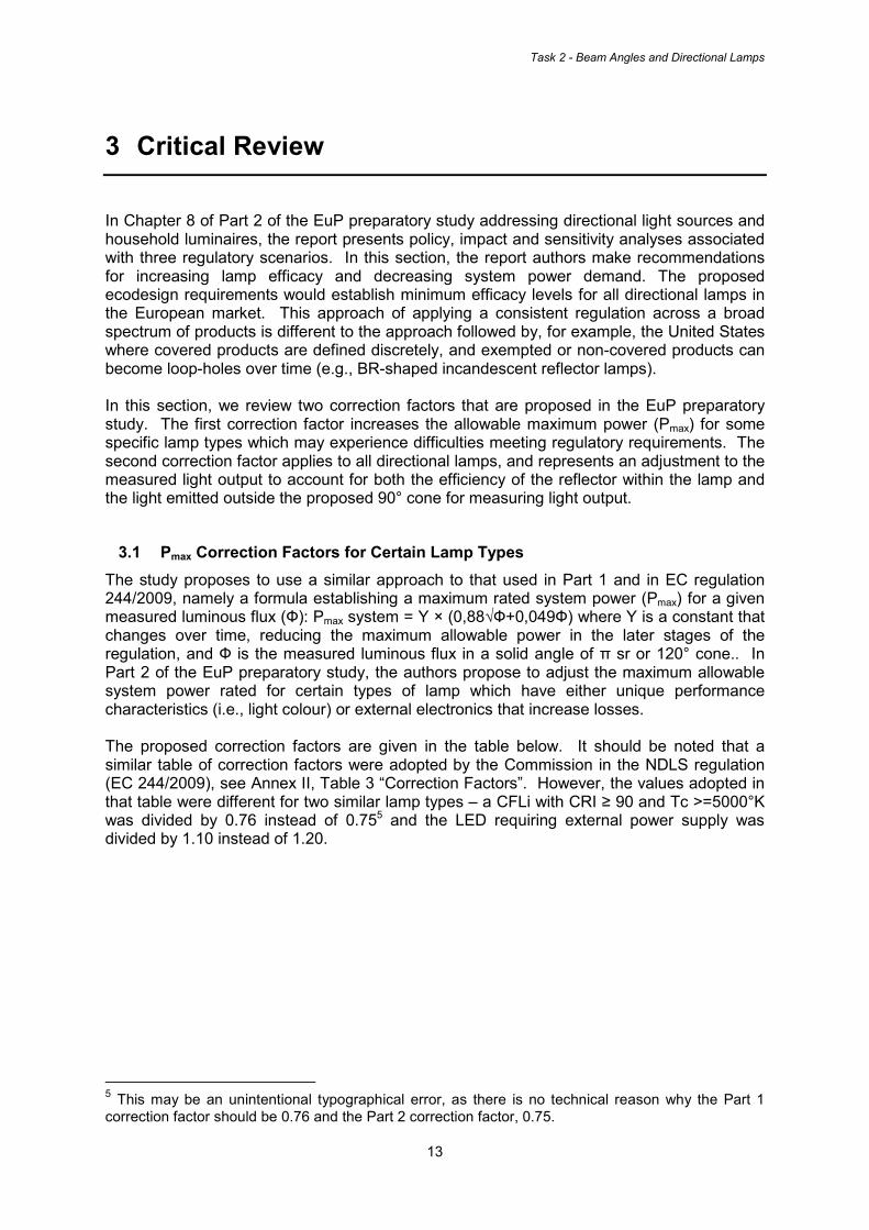
with a 60° beam angle – each will emit different amounts of light outside of the cone of measurement (i.e., 90° cone). However, it is proposed that one adjustment factor of 1.25 would apply to both lamps – this would tend to overstate the luminous flux of the narrow beam lamp relative to the wider beam lamp. Consider the following diagram, where for Lamp A, applying one correction factor to the narrow measurement of the 90° cone would clearly overstate the luminous flux and relative to how 1.25 would affect the correction on Lamp C. The 90° cone angle of measurement is shown in black below the X-axis of the figure.
Figure 3-1. Light Intensity From Various Beam Angle Directional Lamps
b. From an application point of view, it is common to find directional lamps (e.g., MR-16 lamps) being used in general service illumination applications such as area illumination of domestic kitchens and bathrooms, and therefore all forward directional light emitted by the lamp is useful light, whether its within a 90° cone or greater. Thus, from an application perspective, the 180° cone appears as it would constitute a more rational (and accurate) measurement of the lighting service experienced by end-users. In the EUP preparatory study, on page 355 it is stated that the 90° (smaller) cone is better because it would be less expensive to measure. However, it is understood from conversations with lighting testing laboratories conducted in researching for this report, that the incremental cost of measurements in a C-plane by a goniophotometer from -45° to +45° verses -90° to +90° is negligible. The arm sweeps through the range automatically collecting data, and reducing the number of recorded data points only reduces the accuracy of the measurement (and requires application of larger correction factors). [note: see discussion of test procedures in the Task 1 report]
c. On page 549 of the preparatory study, the authors state that beam angles greater than 120° should not be considered because these angles cause glare and are therefore not useful. However glare is an issue at any viewing angle for a visible light source such as an MR-16, and if anyone looks directly at a spot lamp, the result will be discomfort glare. Furthermore, the luminaire into which the light source is installed would manage glare, thus the lamp is not solely responsible for limiting glare from the fitting. Finally, thus glare is not a reason to ignore light emission at angles greater than 120°.

Task 2 - Beam Angles and Directional Lamps
18
d. If the Commission were to expand the functional unit to be 2π steradians (180°), it
would also have the advantage having two possible methods of measuring the light output from the lamp. The goniophotometer approach8 could be used as it is with most directional lamp measurements, or alternatively an integrating sphere could be used, which is a less expensive than a goniophotometer test – although it would need to be calibrated with a reference lamp that is similar in beam angle performance to the one being measured. [See test procedure discussion in Task 1 report]
e. Part of the rationale for the adjustment of 25% is to account for losses in the reflective surface and the reflector lamp optics. However the technical basis for this recommendation is unclear. As shown in Figure 2-3 on page 9 of this report, aluminium (the most common material used to create reflective coatings) maintains a photometric reflectivity greater than 90% across the visible spectrum. It should be noted that the figure shown on this page is from a published text book called the “Handbook of Optics” and thus this figure represents the potential performance of these materials in an optical application such as a reflector lamp. In addition to the reflector, it is understood that there will be some internal light scattering and reflection, as well as supplemental optical losses through the lens of the lamp – and all of these factors do impact the light emission from the lamp. However, directional LED lamps often have “reflector cups” inside the LED package, and therefore do not require a reflector surrounding the package. In the absence of further evidence, the basis for the 25% adjustment is unclear. It may be helpful for the Commission to request additional test report evidence from industry or other parties to review this reduction in efficacy.
f. It is noted that the proposal considered in the EuP study only discusses making adjustments to the maximum rated power requirements of clear lamps from EC 244-2009. The equation for non-clear lamps that applies to NDLS such as CFLi was not addressed in the EuP preparatory study. For directional lamps, it is true that the market is primarily clear lamps, however there may be some directional lamps that are non-clear such as CFLi, LED with remote phosphor, or another technology with a coating/diffuser on the reflector lens, and it is presumed that these non-clear lamps would be held the same (lower relative) clear lamp requirements. Should there be a separate efficacy requirement for directional non-clear lamps, as was done for the NDLS regulation? The table below gives the three maximum power equations for NDLS.
Table 3-4. Regulation for Non-Directional Light Sources, EC 244/2009
Application Date
Maximum rated power (Pmax) for a luminous flux (Ф) (Watts)
Clear Lamps Non-clear Lamps
Stages 1 to 5 0.8 * (0.88√Ф+0.049Ф) 0.24√Ф+0.0103Ф
Stage 6 0.6 * (0.88√Ф+0.049Ф) 0.24√Ф+0.0103Ф
Finally, in the context of this discussion around adjustments for reflector losses, it should be noted that in regulation 244/2009, Annex III, Verification procedure for market surveillance purposes, the regulation states that: “The batch shall be considered to comply with the provisions set out in Annex II as applicable, of this Regulation if the average results of the batch do not vary from the limit, threshold or declared values by more than 10%.” Thus, the 8 It should be noted that a goniophotometer would be required for any conical measurement of light output from a directional lamp which is less than 180°.

Task 2 - Beam Angles and Directional Lamps
19
existing regulation already allows manufacturers to produce and sell lamps that are 10% below the required MEPS regulation. This should be kept in mind when reviewing the magnitude of the correction factors being considered above.
3.3 Other Regulatory Organisations
There are three other regulatory entities that have set minimum performance standards for directional lamps – Australia, Canada and the United States. It is difficult to draw comparisons on the two issues discussed above because of the differences in the scope of coverage for these countries and the EU. In the US and Canada, directional CFLi reflector lamps are not regulated products. Therefore the CRI and CCT correction factors are not necessary. This is also true of LED and HID directional lamps, none of them are covered or regulated in the US at this time. Furthermore, small diameter lamps such as halogen MR-16 lamps (which can be found operating on 12V systems) are not covered or regulated in the US and Canada, as their scope of coverage only extends to an R-18 size diameter (i.e., 2.25 inches) and they only cover lamps with medium screw base. In Australia, reflector lamps are covered and proposed for regulation – including both incandescent and halogen, and large and small diameter (down to MR-16 size) with different base types. Australia is in the process of reviewing its regulatory standards for directional lamps, and is considering revisions (see Task 1 report). However, it should be noted that Australia conducted an independent analysis on the appropriate efficacy requirement, and found that low-voltage halogen MR-16 (HL-LV) lamps could meet the same MEPS requirements as were established for incandescent NDLS MEPS (without correction). The reason for this is that the system efficacy increase from moving to low-voltage operation was offset by the additional optical losses from the reflector. Thus, in their proposal, Australia notified the public that it would be adopting the same regulatory standard for these DLS as it did for NDLS, omitting any mention of a correction factor. This regulation is under review at this time.
3.4 Comparison of Efficacy Requirements
In this section, a graphical comparison is presented which plots the efficacy requirements for Australia, Canada and the United States against the “BAT with lock-in effect” level presented in the EuP preparatory study section on directional lamps. The table below identifies the energy-efficient labels that would be required under the BAT with lock-in effect for the four classes of directional lamps considered in the preparatory study.
Table 3-5. EuP Preparatory Study Level: BAT with Lock-in Effect
Present 2010 2013 2016
GLS-R Level F Level E Level B
HL-MV-R-HW Level D Level C Level B+
HL-MV-R-LW Level F Level E Level D
HL-LV-R Level C Level B Level B Source: EuP Preparatory Study, Lot 19: Domestic Lighting, p.565 Table 8-10 The following table translates these energy-efficiency labels into maximum wattages and efficacies (including control gear losses). These are the equations that were used to calculate efficacy curves in the figures that follow.

Task 2 - Beam Angles and Directional Lamps
20
Table 3-6. New Lamp Efficacy Levels Used in Part 2 of EuP Preparatory Study
Level
Maximum System Power Demand (Psystem) related to lamp
corrected luminous flux (ФR) [W]
Minimum Light Source Efficacy (including control gear losses)
ηsource=ФR/Psystem [lm/W]
Y factor
G >1.30
x (0.88√Ф+0.049ФR)
F 1.30 ФR/1.30
x 1/(0.88√ФR+0.049ФR)
E 1.10 ФR/1.10
D 0.95 ФR/0.95
C 0.8 ФR/0.80
B 0.6 ФR/0.6
B(B+) 0.4 ФR/0.4
A 0.225 ФR/0.225
A(A+) 0.209 ФR/0.209
A(A++) 0.178 ФR/0.178
A(A+++) 0.116 ФR/0.116 Source: EuP Preparatory Study, Lot 19: Domestic Lighting, p.612 Table 8-21 The following diagrams plot the lamp efficacy requirements (lumens per watt) at 240 volts for the Australian, Canadian and United States MEPS on directional lamps. It then super-imposes the levels considered in the “BAT with lock-in effect” presented in the EuP Preparatory Study on Domestic Lighting (part 2, which includes directional lamps). Figure 3-2 and Figure 3-3 both present the comparison at the 2013 level, however Figure 3-3 is an expanded view, to show more detail at the more common, lower wattage levels.
Figure 3-2. Comparative Efficacy Plot, including BAT with Lock-In Effect, 2013 (240V)

Task 2 - Beam Angles and Directional Lamps
21
The figure shows that the EU Label Level E which would be required for general service reflector lamps (GLS-R) and halogen line voltage reflector lamps with low wattage (HL-MV-R-LW) in 2013 is slightly higher than the 1992 EPACT level in the US and Canada, once that requirement has been adjusted from 120 volts to 240. Line voltage halogen directional lamps with higher wattage ratings (HL-MV-R-HW) is approximately in line with the Australian regulation and the US DOE large-diameter incandescent reflector lamp levels that take effect in 2012. Halogen low-voltage reflector lamps (HL-LV-R) have the highest efficacy requirement of any directional lamp in 2013, nearly double the efficacy requirement of a 600 lumen GLS-R lamp in 2013. Figure 3-3 presents the same data as Figure 3-2, however the view has been expanded to reveal more detail of the lower wattage levels, which represent the volume of the directional lamp market.
Figure 3-3. Expanded View of Efficacy Comparison, BAT with Lock-In, 2013 (240V) Figure 3-4 presents the 2016 level considered in the EuP preparatory study BAT with lock-in effect levels.

Task 2 - Beam Angles and Directional Lamps
22
Figure 3-4. Comparative Efficacy Plot, including BAT with Lock-In Effect, 2016 (240V) By 2016, the HL-MV-R-HW, HL-LV-R and GLS-R are all well above the other regulatory levels adopted for 2012 by Australia, Canada and the US. The least efficient EU level, label D for HL-MV-R-LW is approximately equal to the US small diameter incandescent reflector lamp efficacy requirement adjusted for 240 V.
Task 2 - Beam Angles and Directional Lamps
23
4 Conclusions
The following conclusions can be drawn from the work analysed in this report:
• The EC defines a ‘Directional Light Source’ as a light source having at least 80% of its light output within a solid angle of π sr (corresponding to a cone angle of 120°). However, the EuP preparatory study proposes to measure light output in a 90° cone angle (or 120° for certain special lamps), and then to apply an correction factor (multiply by 1.25) to account for internal reflector losses and spill light emitted outside of the cone angle of measurement. It is suggested that the Commission explore the option of adopting a simpler and more accurate measurement of all forward lumens in a 180° cone.
• Many installations of directional lamps are actually operated as general service
reflector lamps, particularly the small and popular MR-16 lamps. Measurement of luminous flux at specific cone angles is expensive and time consuming, and does not represent how these lamps are commonly used when installed in homes and businesses.
• In addition to the 1.25 adjustment for measured light output, the EuP preparatory
study recommends making four discrete corrections to Pmax to account for system watts that would account for unique light qualities from CFLi, and from external power supply losses for low-voltage halogen and LED. Some of these correction factors warrant further study. The four lamp types are:
o CFLi lamp with CRI ≥ 90 o CFLi lamp with CRI ≥ 90 and Tc >=5000°K o (Safe) Extra Low Voltage lamps requiring external power supply for mains
connections excluding LED. o LED requiring external power supply
• Internationally, none of the other governments regulating reflector lamps have
adopted this approach of adjustments and corrections, however no other government has a scope of coverage as broad as Europe. The European scope has an advantage in this respect as it is defined around an application (i.e., directional lighting) as opposed to be defined around a technology (i.e., incandescent and halogen lamps).

Task 2 - Beam Angles and Directional Lamps
24
References 10 CFR Part 430.32(n) General Service Fluorescent Lamps and Incandescent Reflector Lamps. Accessed via the Electronic Code of Federal Register, 30th March 2010. 10 CFR Part 430 Appendix R to Subpart B --Uniform Test Method for Measuring Average Lamp Efficacy (LE), Color Rendering Index (CRI), and Correlated Color Temperature (CCT) of Electric Lamps; accessed via the Electronic Code of Federal Register, 31st March 2010. AS/NZS 4934.1(Int):2008; Interim Australian/New Zealand Standard™; Incandescent lamps for general lighting service: Part 1: Test methods—Energy performance. Prepared by Joint Technical Committee EL-041, Lamps and Related Equipment. It was approved on behalf of the Council of Standards Australia on 18 February 2008 and on behalf of the Council of Standards New Zealand on 18 March 2008. This Standard was published on 7 April 2008.
AS/NZS 4934.2(Int):2008; Interim Australian/New Zealand Standard™; Incandescent lamps for general lighting services: Part 2: Minimum Energy Performance Standards (MEPS) requirements. It was prepared by Joint Technical Committee EL-041, Lamps and Related Equipment. It was approved on behalf of the Council of Standards Australia on 7 March 2008 and on behalf of the Council of Standards New Zealand on 18 March 2008. This Standard was published on 7 April 2008.
Bass, 1994. Handbook of Optics, Volume 2, Second Edition. M. Bass and E.W. Van Stryland, editors. Published by McGraw-Hill, New York, 1994.
CSA C862-09: Performance of incandescent reflector lamps; Canadian Standards Association, Mississauga, Ontario, Canada; Published in November 2009.
DOE, 2009. Energy Conservation Program: Energy Conservation Standards and Test Procedures for General Service Fluorescent Lamps and Incandescent Reflector Lamps; Final Rule; US Department of Energy, published in the Federal Register, volume 74, Number 133, page 34080 on Tuesday, July 14, 2009.
EC, 2009: European Commission Regulation No 244/2009 of 18 March 2009 implementing Directive 2005/32/EC of the European Parliament and of the Council with regard to ecodesign requirements for non-directional household lamps. Official Journal of the European Union, 24 March 2009. Accessed on line on 29 March 2010: http://eur-lex.europa.eu/LexUriServ/LexUriServ.do?uri=OJ:L:2009:076:0003:0016:EN:pdf
IESNA, 1995. The Lighting Handbook, Reference and Application. Mark S. Rea, Editor-in-Chief, Rensselaer Polytechnic Institute. Illuminating Engineering Society of North America, New York, 1995.
IFC, 2006. ELI Technical Documents for Certification, First edition, 2006-03-01: “ELI Voluntary Technical Specification for Self-Ballasted Compact Fluorescent Lamps (CFLs)”, the International Finance Corporation, the World Bank Group, 2006.
Manufacturer lamp catalogues for Philips Lighting, General Electric Lighting and Osram, 2009-2010; accessed on line during April 2010.
NRCan, 2009. Canada's Energy Efficiency Regulations: General Service Incandescent Reflector Lamps; First Bulletin on Amending the Standards, January 2009 Accessed on line: http://oee.nrcan.gc.ca/regulations/bulletin/reflector-lamps-jan09.cfm?attr=0

Task 2 - Beam Angles and Directional Lamps
25
VITO, 2009. Preparatory Studies for Eco-design Requirements of EuPs, Final report Lot 19: Domestic lighting. Prepared by VITO, Bio Intelligence Service, Energy Piano and Kreios for European Commission DGTREN unit D3; ContractTREN/07/D3/390-2006/S07.72702; 2009/ETE/R/069; October 2009

Task 2 - Beam Angles and Directional Lamps
26