TAS5782M Process Flows (Rev. B) - TI.com · TAS5782M process flows with SmartAmp Processing...
89
1 SLAA737B – March 2017 – Revised October 2017 Submit Documentation Feedback Copyright © 2017, Texas Instruments Incorporated TAS5782M Process Flows Application Report SLAA737B – March 2017 – Revised October 2017 TAS5782M Process Flows Andy Liu (AIP) ABSTRACT The TAS5782M device has a powerful μCDSP audio processing core, which supports several selectable process flows. This application report explains details of each process flow. The TAS5782M process flows with standard processing, feature a few advanced audio processing blocks: Dynamic Ranger Control (DRC), Automatic Gain Limiter (AGL), Dynamic Parametric Equalizer (DPEQ) and Spatializer. A 3-band DRC + AGL structure limits the output power of the amplifier for three regions while controlling the peaking that can occur in the crossover region during compression. DPEQ dynamically adjusts the equalization curve that is applied to low-level signal and the curve that is applied to high level signals. Spatializer increases the field of sound for a broader and more encompassing audio experience. TAS5782M process flows with SmartAmp Processing replaces traditional continuous power design principles and hardware-based speaker protection methods with algorithms that allow significant increases in peak power output, loudness, and sound quality relative to conventional amplifiers. Smart Amp tools allow developers to understand how speakers are performing in the system and then make informed decisions to improve performance. The algorithms, characterization, and tuning tools allow developers to overcome a wide variety of audio challenges. Contents 1 General Overview............................................................................................................ 3 2 Process Flows Cross Reference........................................................................................... 5 3 Process Flow 1 (96 kHz, 2.0 Standard Processing) .................................................................... 6 4 Process Flow 2 (96 kHz, 2.0 SmartAmp Processing) ................................................................... 8 5 Process Flow 3 (48 kHz, 2.0 Standard Processing) ................................................................... 10 6 Process Flow 4 (48 kHz, 2.0 SmartAmp Processing) ................................................................. 12 7 Process Flow 5 (48 kHz, 2.1 Standard Processing) ................................................................... 14 8 Process Flow 6 (48 kHz, 2.1 SmartAmp Processing) ................................................................. 16 9 Audio Processing Blocks .................................................................................................. 18 10 Smart Amp .................................................................................................................. 32 11 Loudspeaker Characterization ............................................................................................ 36 12 Smart Amp Tuning ......................................................................................................... 39 Appendix A DSP Memory Map................................................................................................. 46 Appendix B Power-Up and Power-Down Sequence ........................................................................ 87 List of Figures 1 TAS5782M Functional Block Diagram .................................................................................... 3 2 Process Flow 1............................................................................................................... 6 3 Process Flow 2............................................................................................................... 8 4 Process Flow 3 ............................................................................................................. 10 5 Process Flow 4 ............................................................................................................. 12 6 Process Flow 5 ............................................................................................................. 14 7 Process Flow 5 ............................................................................................................. 16 8 Input Mixer .................................................................................................................. 18 9 Input Mixer (Basic Tab).................................................................................................... 18
Transcript of TAS5782M Process Flows (Rev. B) - TI.com · TAS5782M process flows with SmartAmp Processing...

1SLAA737B–March 2017–Revised October 2017Submit Documentation Feedback
Copyright © 2017, Texas Instruments Incorporated
TAS5782M Process Flows
Application ReportSLAA737B–March 2017–Revised October 2017
TAS5782M Process Flows
Andy Liu (AIP)
ABSTRACTThe TAS5782M device has a powerful µCDSP audio processing core, which supports several selectableprocess flows. This application report explains details of each process flow.
The TAS5782M process flows with standard processing, feature a few advanced audio processing blocks:Dynamic Ranger Control (DRC), Automatic Gain Limiter (AGL), Dynamic Parametric Equalizer (DPEQ)and Spatializer. A 3-band DRC + AGL structure limits the output power of the amplifier for three regionswhile controlling the peaking that can occur in the crossover region during compression. DPEQdynamically adjusts the equalization curve that is applied to low-level signal and the curve that is appliedto high level signals. Spatializer increases the field of sound for a broader and more encompassing audioexperience.
TAS5782M process flows with SmartAmp Processing replaces traditional continuous power designprinciples and hardware-based speaker protection methods with algorithms that allow significant increasesin peak power output, loudness, and sound quality relative to conventional amplifiers. Smart Amp toolsallow developers to understand how speakers are performing in the system and then make informeddecisions to improve performance. The algorithms, characterization, and tuning tools allow developers toovercome a wide variety of audio challenges.
Contents1 General Overview............................................................................................................ 32 Process Flows Cross Reference........................................................................................... 53 Process Flow 1 (96 kHz, 2.0 Standard Processing) .................................................................... 64 Process Flow 2 (96 kHz, 2.0 SmartAmp Processing)................................................................... 85 Process Flow 3 (48 kHz, 2.0 Standard Processing) ................................................................... 106 Process Flow 4 (48 kHz, 2.0 SmartAmp Processing) ................................................................. 127 Process Flow 5 (48 kHz, 2.1 Standard Processing) ................................................................... 148 Process Flow 6 (48 kHz, 2.1 SmartAmp Processing) ................................................................. 169 Audio Processing Blocks .................................................................................................. 1810 Smart Amp .................................................................................................................. 3211 Loudspeaker Characterization............................................................................................ 3612 Smart Amp Tuning ......................................................................................................... 39Appendix A DSP Memory Map................................................................................................. 46Appendix B Power-Up and Power-Down Sequence ........................................................................ 87
List of Figures
1 TAS5782M Functional Block Diagram .................................................................................... 32 Process Flow 1............................................................................................................... 63 Process Flow 2............................................................................................................... 84 Process Flow 3 ............................................................................................................. 105 Process Flow 4 ............................................................................................................. 126 Process Flow 5 ............................................................................................................. 147 Process Flow 5 ............................................................................................................. 168 Input Mixer .................................................................................................................. 189 Input Mixer (Basic Tab).................................................................................................... 18
www.ti.com
2 SLAA737B–March 2017–Revised October 2017Submit Documentation Feedback
Copyright © 2017, Texas Instruments Incorporated
TAS5782M Process Flows
10 Input Mixer (Advanced Tab) .............................................................................................. 1911 Cascaded BQ Structure ................................................................................................... 1912 Equalizer Tuning Window ................................................................................................. 2013 Volume....................................................................................................................... 2114 Volume Attack and Decay ................................................................................................ 2115 Spatializer Block Diagram ................................................................................................ 2216 Spatializer Tuning Window................................................................................................ 2217 DPEQ ........................................................................................................................ 2318 DPEQ Tuning Window..................................................................................................... 2419 Bass Mono Mixer........................................................................................................... 2520 3-Band DRC ................................................................................................................ 2521 DRC Attack and Decay.................................................................................................... 2622 DRC Tuning Window ...................................................................................................... 2623 AGL Tuning Window....................................................................................................... 2724 AGL Attack and Release .................................................................................................. 2825 Crossover Tuning Window ................................................................................................ 2926 Phase Delay Tuning Window ............................................................................................. 3027 Clipper ....................................................................................................................... 3028 Output Crossbar (Basic Tab) ............................................................................................. 3129 Output Crossbar (Advanced Tab)........................................................................................ 3130 Audio Clip A, 22-dB Peak-to-Average Ratio Source .................................................................. 3231 Audio Clip B, 9-dB Peak-to-Average Ratio Source .................................................................... 3232 PurePath™ Smart Amp Block Diagram ................................................................................. 3333 Smart Amp Development Overview ..................................................................................... 3434 Smart Amp Tuning Process............................................................................................... 3935 Smart Amp Tuning Page .................................................................................................. 4236 Power-Up Timing........................................................................................................... 8737 Power-Down Timing ....................................................................................................... 88
List of Tables
1 Supported Use Cases....................................................................................................... 42 Process Flows 1–4 .......................................................................................................... 53 Process Flows 5–6 .......................................................................................................... 54 BQ Coefficients Normalization............................................................................................ 195 Recommended Presets Available in the GUI........................................................................... 236 Bass Enhancement Parameters ......................................................................................... 437 DSP Memory Map for Process Flow 1 — Book 0x8C................................................................. 468 DSP Memory Map for Process Flow 2 — Book 0x8C................................................................. 519 DSP Memory Map for Process Flow 3 — Book 0x8C................................................................. 5610 DSP Memory Map for Process Flow 4 — Book 0x8C................................................................. 6311 DSP Memory Map for Process Flow 5 — Book 0x8C................................................................. 7012 DSP Memory Map for Process Flow 6 — Book 0x8C................................................................. 79
TrademarksPurePath is a trademark of Texas Instruments.All other trademarks are the property of their respective owners.

SPK_OUTB+
SPK_OUTB-
SPK_OUTA+
SPK_OUTA-
SCLK
SDIN
MCLK
LRCK/FS
DV
DD
CP
VD
D
GV
DD
_RE
G
PV
DD
SPK_GAIN/FREQ
DA
C_O
UT
A
DA
C_O
UT
B
SP
K_I
NB
±
SP
K_I
NA
±
Internal Gate Drive Regulator
RESETGPIO0 GPIO2 ADR1
CP
CN
DV
DD
_RE
G
CP
VS
SAnalog
toPWM
Modulator
Gate Drives
Full Bridge Power
Stage AOutput Current
Monitoring and
ProtectionFull Bridge Power
Stage B
Gate Drives
Closed Loop Class D Amplifier
1.8-V Regulator
Internal Voltage Supplies
Charge Pump
Serial Audio Port
µCDSP
Selectable
Process
Flows
DAC
Internal Control Registers and State Machines
Clock Monitoring and Error Protection
Die TemperatureMonitoring and Protection
ADR0SDASCLSPK_FAULTSPK_SD
Error ReportingSDOUTA
VD
D
Internal Voltage Supplies
SPK_MUTE
Copyright © 2016, Texas Instruments Incorporated
www.ti.com General Overview
3SLAA737B–March 2017–Revised October 2017Submit Documentation Feedback
Copyright © 2017, Texas Instruments Incorporated
TAS5782M Process Flows
1 General OverviewIn the signal processing path, a µCDSP audio processing core is placed after the Serial Audio Port andbefore the Digital-to-Analog Converter (DAC), which precedes the Class D amplifier. This is illustrated inFigure 1.
Figure 1. TAS5782M Functional Block Diagram
The µCDSP processor is thought of as a 2-input and 2-output digital signal processor. The two inputchannels can come from a TDM stream, or a traditional I2S, left-justified or right-justified serial audio inputstream and are presented to the µCDSP through the serial audio port. The controls that configure theserial audio port to accept various input formats are detailed in the TAS5782M device data sheet(SLASEG8).

General Overview www.ti.com
4 SLAA737B–March 2017–Revised October 2017Submit Documentation Feedback
Copyright © 2017, Texas Instruments Incorporated
TAS5782M Process Flows
1.1 Supported Use CasesThe TAS5782M process flows have been generated based upon several popular configurations, primarilyaround the number and type of amplified outputs. Table 1 shows the use cases supported by availableprocess flows and PPC3 GUI.
Table 1. Supported Use Cases
Mode Also Known As Amplifier Output Configuration Symbol in PPC3 GUI2.0 Stereo One device drives two full-range speakers in stereo.
2.2 Dual stereo Two devices drive two-way speakers in stereo. One devicedrives two tweeters and one device drives two woofers.
2.2 Dual stereo Two devices drive two-way speakers in stereo. One devicedrives the left speaker and one device drives the right speaker.
1.1 Bi-amped, dualmono
A single input signal is separated into high- and low-frequencycontent. One BTL output drives a high-frequency transducerand the other drives a low-frequency transducer.
2.1 N/A One device uses 2.0 mode and a separate device uses monomode.
Mono 0.1 A single signal, created from one or both of the two inputsignals sent via a single output created by placing the twooutput channels in parallel into a single channel, usually todrive more power

www.ti.com Process Flows Cross Reference
5SLAA737B–March 2017–Revised October 2017Submit Documentation Feedback
Copyright © 2017, Texas Instruments Incorporated
TAS5782M Process Flows
2 Process Flows Cross ReferenceTable 2 and Table 3show the processing features of each process flow available in the current PPC3 GUI.
Table 2. Process Flows 1–4
FeatureProcess Flow 1
(96 kHz, 2.0 StandardProcessing)
Process Flow 2(96 kHz, 2.0SmartAMP
Processing)
Process Flow 3(48 kHz, 2.0
StandardProcessing)
Process Flow 4(48 kHz, 2.0SmartAMP
Processing)Maximum Internal Sample Rate 96 kHz 96 kHz 48 kHz 48 kHzSRC (2× Decimator) and Auto-detect (96 kHz -> 48 kHz or 88.2kHz to 44.1 kHz)
× × √ √
Supported Input Sample Rates(16 kHz, 32 kHz, 44.1 kHz, 48 kHz,88.2 kHz and 96 kHz)
√ √ √ √
Biquads for EQ Filtering (IndividualLeft and Right)
12 12 15 15
Input Mixer √ √ √ √Click and Pop Free Volume √ √ √ √Spatializer (Stereo Widening) × × √ √Dynamic Biquad × × √ √Bass Mono Mixer × × √ √3-Band DRC (2nd order) √ × √ ×AGL √ × √ ×Smart Excursion, Smart Thermal,and Smart Bass
× √ × √
Output Clipper √ √ √ √
Table 3. Process Flows 5–6
FeatureProcess Flow 5
(48 kHz, 2.1 StandardProcessing)
Process Flow 6(48kHz, 2.1 SmartAMP
Processing)Maximum Internal Sample Rate 48 kHz 48 kHzSupported Input Sample Rates (16 kHz, 32kHz, 44.1 kHz, and 48 kHz)
√ √
Biquads for EQ Filtering (Individual Leftand Right)
15 15
Input Mixer √ √Click and Pop Free Volume √ √Spatializer (Stereo Widening) √ √Dynamic Biquad √ √Bass Mono Mixer × ×3-Band DRC (2nd order) √ ×Automatic Gain Limiter √ ×Smart Excursion, Smart Thermal andSmart Bass
× √
Output Clipper √ √

Input
Mixer
12 BQsWith
SmartEQ
Clipper
AMP
L
AMP
R
I2S Out
L
Crossbar
2:4
(With
Invert)
Volume
I2S Out
R
Audio In AGL3-Band DRC
(2nd
Order)
Process Flow 1 (96 kHz, 2.0 Standard Processing) www.ti.com
6 SLAA737B–March 2017–Revised October 2017Submit Documentation Feedback
Copyright © 2017, Texas Instruments Incorporated
TAS5782M Process Flows
3 Process Flow 1 (96 kHz, 2.0 Standard Processing)This process flow supports an internal sample rate of 96 kHz and is therefore considered “true” 96 kHz. Itis intended for stereo speakers where the 3-band Dynamic Range Control (DRC) and AGL will have thesame coefficients for left and right. It is possible to tune the left and right Biquads (BQs) in the 12-BQ bankindividually between left and right.
Figure 2 depicts the signal path of this flow. The blocks in Figure 2 correspond to the functions found inthe PPC3 GUI.
Figure 2. Process Flow 1
3.1 Input MixerThe input mixer is used to mix the left and right channel input signals. Refer to Section 9.1 for moredetails.
3.2 EqualizerThe equalizer contains 12 independent filters for both left and right channels. Refer to Section 9.2 for moredetails.
3.3 VolumeThis volume block is click and pop free. Refer to Section 9.3 for more details.
3.4 3-Band DRCThe 3-Band DRC can be used to automatically control the audio signal amplitude or the dynamic rangewithin specified limits. Refer to Section 9.4 for more details.
3.5 AGLThe AGL can also be used to automatically control the audio signal amplitude or dynamic range withinspecified limits. Refer to Section 9.5 for more details.
3.6 ClipperA THD boost and fine volume together can be used for clipping. The THD boost block allows the user toprogrammatically increase the THD by clipping at an operating point earlier than that defined by the supplyrails. Refer to Section 9.11 for more details.

www.ti.com Process Flow 1 (96 kHz, 2.0 Standard Processing)
7SLAA737B–March 2017–Revised October 2017Submit Documentation Feedback
Copyright © 2017, Texas Instruments Incorporated
TAS5782M Process Flows
3.7 Output CrossbarThe crossbar provides the end user with a very flexible way to control what finally appears on amplifieroutputs and I2S SDOUT. Refer to Section 9.12 for more details.
3.8 DSP Memory MapRefer to Section A.1 for the details.

Input
Mixer
12 BQsWith
SmartEQ
Clipper
AMP
L
AMP
R
I2S Out
L
Crossbar
2:4
(With
Invert)
Volume
I2S Out
R
Audio In
Thermal
Limiter
SmartAmp
SmartBass
With Morphing
Excursion
Limiter
SmartAmp
Process Flow 2 (96 kHz, 2.0 SmartAmp Processing) www.ti.com
8 SLAA737B–March 2017–Revised October 2017Submit Documentation Feedback
Copyright © 2017, Texas Instruments Incorporated
TAS5782M Process Flows
4 Process Flow 2 (96 kHz, 2.0 SmartAmp Processing)This process flow supports an internal sample rate of 96 kHz and is therefore considered “true” 96 kHz.This process flow is similar to process flow 1. The difference is the 3-Band DRC and AGL is removed tofree up processing resources for these three components: SmartBass with morphing, Excursion Limiter,and Thermal Limiter.
Figure 3 depicts the signal path of this process flow. The blocks in Figure 3 correspond to the functionsfound in the PPC3 GUI.
Figure 3. Process Flow 2
4.1 Input MixerThe input mixer is used to mix the left and right channel input signals. Refer to Section 9.1 for moredetails.
4.2 EqualizerThe equalizer contains 12 independent filters for both left and right channels. Refer to Section 9.2 for moredetails.
4.3 VolumeThis volume block is click and pop free. Refer to Section 9.3 for more details.
4.4 Smart Bass, Excursion Limiter and Thermal LimiterSmart Bass is an intelligent True Bass Alignment algorithm. Smart Bass uses the combination of thespeaker model and a desired target response selected by the user to equalize the speaker in the bassregion. This target response is critical for the sound character and the user can apply the same targetresponse to very different speakers and get the same sound. Refer to Section 10 to Section 12 for moredetails.
Based on mechanical, electrical, and acoustical properties of speakers, Excursion Limiter and ThermalLimiter can predict potentially damaging situations, take timely precautions and therefore protect speakersfrom over-excursion and overheating.
4.5 ClipperA THD boost and fine volume together can be used for clipping. The THD boost block allows the user toprogrammatically increase the THD by clipping at an operating point earlier than that defined by the supplyrails. Refer to Section 9.11 for more details.
www.ti.com Process Flow 2 (96 kHz, 2.0 SmartAmp Processing)
9SLAA737B–March 2017–Revised October 2017Submit Documentation Feedback
Copyright © 2017, Texas Instruments Incorporated
TAS5782M Process Flows
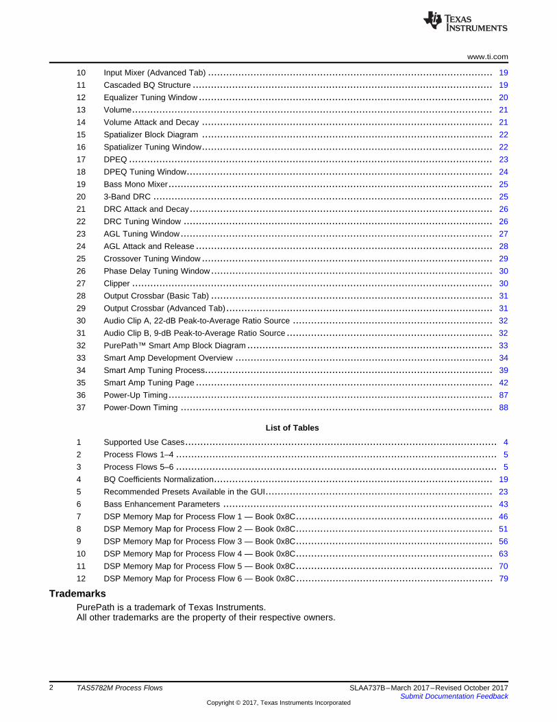
4.6 Output CrossbarThe crossbar provides the end user with a very flexible way to control what finally appears on amplifieroutputs and I2S SDOUT. Refer to Section 9.12 for more details.
4.7 DSP Memory MapRefer to Section A.2 for the details.

Audio InInput
Mixer
15 BQs
SmartEQ DPEQVolume
Bass Mono
MixerAGL
3-Band DRC(2
nd Order)
Spatializer2x
DecimatorClipper
AMP
L
AMP
L
AMP
R
AMP
R
I2S out
L
I2S out
L
Crossbar
2:4
I2S out
R
I2S out
R
Process Flow 3 (48 kHz, 2.0 Standard Processing) www.ti.com
10 SLAA737B–March 2017–Revised October 2017Submit Documentation Feedback
Copyright © 2017, Texas Instruments Incorporated
TAS5782M Process Flows
5 Process Flow 3 (48 kHz, 2.0 Standard Processing)This process flow supports an internal sample rate of 48 kHz. It can accept both 48- and 96-kHz inputsample rate but will down sample the 96 kHz to 48 kHz with a 2× decimator. Compared to the true 96-kHzprocess flow, this flow will have the same features but will on top of that also support: 2× decimator, 4thorder DPEQ, and bass mono mixer.
Figure 4 depicts the signal path of this process flow. The blocks in Figure 4 correspond to the functionsfound in the PPC3 GUI.
Figure 4. Process Flow 3
5.1 Input MixerThe input mixer is used to mix the left and right channel input signals. Refer to Section 9.1 for moredetails.
5.2 DecimatorA decimator is added in order to support the “pseudo 96 kHz” mode. The device will accept 96-kHzsample rate and internally decimate it to 48 kHz for further processing.
5.3 EqualizerThe equalizer contains 15 independent filters for both left and right channels. Refer to Section 9.2 for moredetails.
5.4 VolumeThis volume block is click and pop free. Refer to Section 9.3 for more details.
5.5 SpatializerSpatializer is a method to increase the field of sound for a broader and more encompassing audioexperience. Refer to Section 9.4 for more details.
5.6 DPEQThe dynamic parametric equalizer is used to mix the audio signals through two signal paths (low level andhigh level). These two paths are used with separate equalization properties. A third path monitors theincoming audio and determines the thresholds and mixing characteristics between these two paths. Thus,the mix between the two high- and low-level DBE channels is dynamic in nature and depends on theincoming audio. Refer to Section 9.5 for more details.
5.7 Bass Mono MixerThe bass mono mixer is used to mix left and right channels, effectively creating a mono signal below aconfigurable frequency on both channels. Refer to Section 9.6 for more details.

www.ti.com Process Flow 3 (48 kHz, 2.0 Standard Processing)
11SLAA737B–March 2017–Revised October 2017Submit Documentation Feedback
Copyright © 2017, Texas Instruments Incorporated
TAS5782M Process Flows
5.8 3-Band DRCThe 3-Band DRC can be used to automatically control the audio signal amplitude or the dynamic rangewithin specified limits. Refer to Section 9.7 for more details.
5.9 AGLThe AGL can also be used to automatically control the audio signal amplitude or dynamic range withinspecified limits. Refer to Section 9.8 for more details.
5.10 ClipperA THD boost and fine volume together can be used for clipping. The THD boost block allows the user toprogrammatically increase the THD by clipping at an operating point earlier than that defined by the supplyrails. Refer to Section 9.11 for more details.
5.11 Output CrossbarThe crossbar provides the end user with a very flexible way to control what finally appears on amplifieroutputs and I2S SDOUT. Refer to Section 9.12 for more details.
5.12 DSP Memory MapRefer to Section A.3 for the details.

Audio InInput
Mixer
15 BQswIth
SmartEQ
DPEQVolumeBass Mono
Mixer
Excursion
Limiter
SmartAmp
SmartBass
wIth MorphingSpatializer
2x
DecimatorClipper
Crossbar
2:4
Thermal
Limiter
SmartAmp
AMP
L
AMP
R
I2S Out
L
I2S Out
R
Process Flow 4 (48 kHz, 2.0 SmartAmp Processing) www.ti.com
12 SLAA737B–March 2017–Revised October 2017Submit Documentation Feedback
Copyright © 2017, Texas Instruments Incorporated
TAS5782M Process Flows
6 Process Flow 4 (48 kHz, 2.0 SmartAmp Processing)This process flow supports an internal sample rate of 48 kHz. It can accept both 48- and 96-kHz inputsample rate but will down sample the 96 kHz to 48 kHz with a 2× decimator.
The process flow is similar to Process Flow 3. The difference is the 3-Band DRC and AGL is removed tofree up processing resources for these three components: SmartBass with morphing, Excursion Limiter,and Thermal Limiter.
Figure 5 depicts the signal path of this flow. The blocks in Figure 5 correspond to the functions found inthe PPC3 GUI.
Figure 5. Process Flow 4
6.1 Input MixerThe input mixer is used to mix the left and right channel input signals. Refer to Section 9.1 for moredetails.
6.2 DecimatorA decimator is added in order to support the “pseudo 96 kHz” mode. The device will accept 96-kHzsample rate and internally decimate it to 48 kHz for further processing.
6.3 EqualizerThe equalizer contains 15 independent filters for both left and right channels. Refer to Section 9.2 for moredetails.
6.4 VolumeThis volume block is click and pop free. Refer to Section 9.3 for more details.
6.5 SpatializerSpatializer is a method to increase the field of sound for a broader and more encompassing audioexperience. Refer to Section 9.4 for more details.
6.6 DPEQThe dynamic parametric equalizer is used to mix the audio signals through two signal paths (low level andhigh level). These two paths are used with separate equalization properties. A third path monitors theincoming audio and determines the thresholds and mixing characteristics between these two paths. Thus,the mix between the two high- and low-level DBE channels is dynamic in nature and depends on theincoming audio. Refer to Section 9.5 for more details.
6.7 Bass Mono MixerThe bass mono mixer is used to mix left and right channels, effectively creating a mono signal below aconfigurable frequency on both channels. Refer to Section 9.6 for more details.
www.ti.com Process Flow 4 (48 kHz, 2.0 SmartAmp Processing)
13SLAA737B–March 2017–Revised October 2017Submit Documentation Feedback
Copyright © 2017, Texas Instruments Incorporated
TAS5782M Process Flows
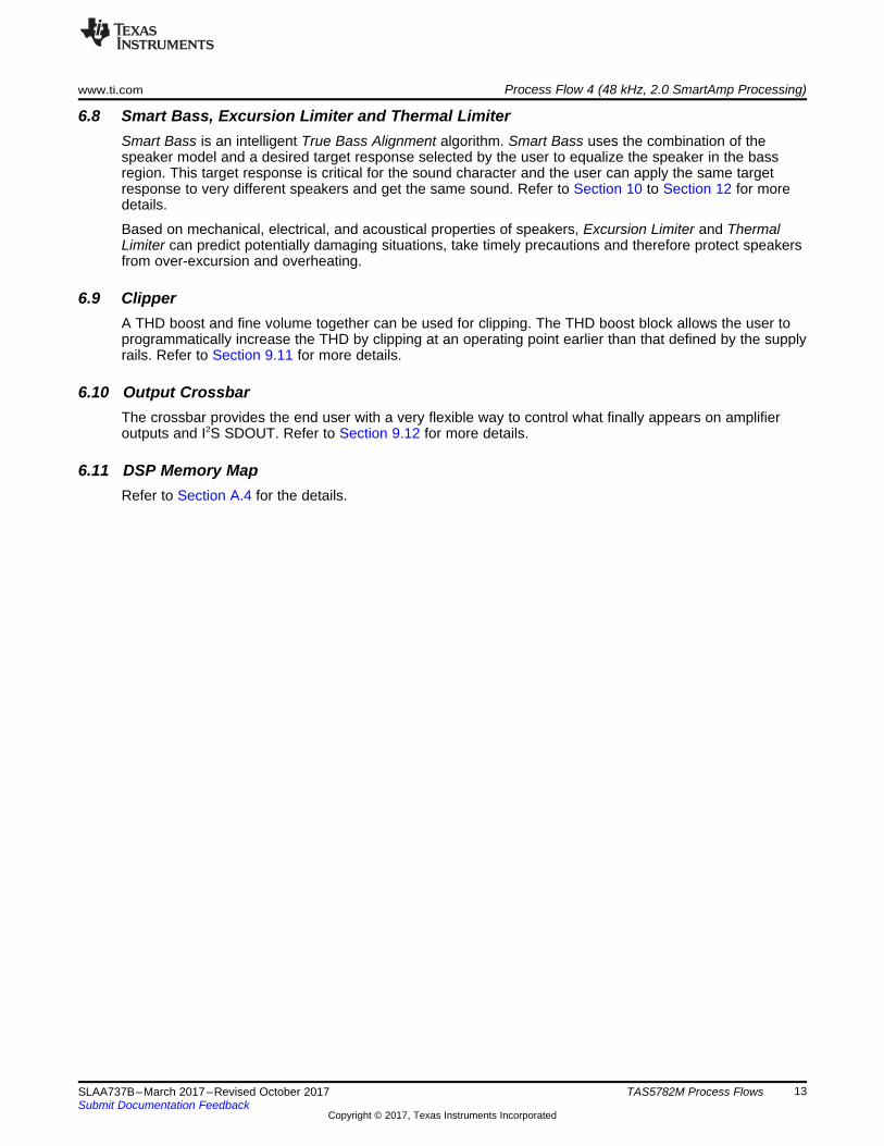
6.8 Smart Bass, Excursion Limiter and Thermal LimiterSmart Bass is an intelligent True Bass Alignment algorithm. Smart Bass uses the combination of thespeaker model and a desired target response selected by the user to equalize the speaker in the bassregion. This target response is critical for the sound character and the user can apply the same targetresponse to very different speakers and get the same sound. Refer to Section 10 to Section 12 for moredetails.
Based on mechanical, electrical, and acoustical properties of speakers, Excursion Limiter and ThermalLimiter can predict potentially damaging situations, take timely precautions and therefore protect speakersfrom over-excursion and overheating.
6.9 ClipperA THD boost and fine volume together can be used for clipping. The THD boost block allows the user toprogrammatically increase the THD by clipping at an operating point earlier than that defined by the supplyrails. Refer to Section 9.11 for more details.
6.10 Output CrossbarThe crossbar provides the end user with a very flexible way to control what finally appears on amplifieroutputs and I2S SDOUT. Refer to Section 9.12 for more details.
6.11 DSP Memory MapRefer to Section A.4 for the details.
Audio InInput
Mixer
15 BQs
w/ SmartEQ
Crossover
(5 BQs)
DPEQ(4th Order)
Volume
Crossover
(5 BQs)
AGL3-Band DRC
(2nd
Order)
Spatializer
Clipper
Crossbar
3:40.1 (Woofer)
Phase
Optimizer
(Delay)
Phase
Optimizer
(Delay)
AGL3-Band DRC
(2nd
Order)Clipper
2.0 (Tweeter)
AMP
L
AMP
R
I2S Out
L
I2S Out
R
Process Flow 5 (48 kHz, 2.1 Standard Processing) www.ti.com
14 SLAA737B–March 2017–Revised October 2017Submit Documentation Feedback
Copyright © 2017, Texas Instruments Incorporated
TAS5782M Process Flows
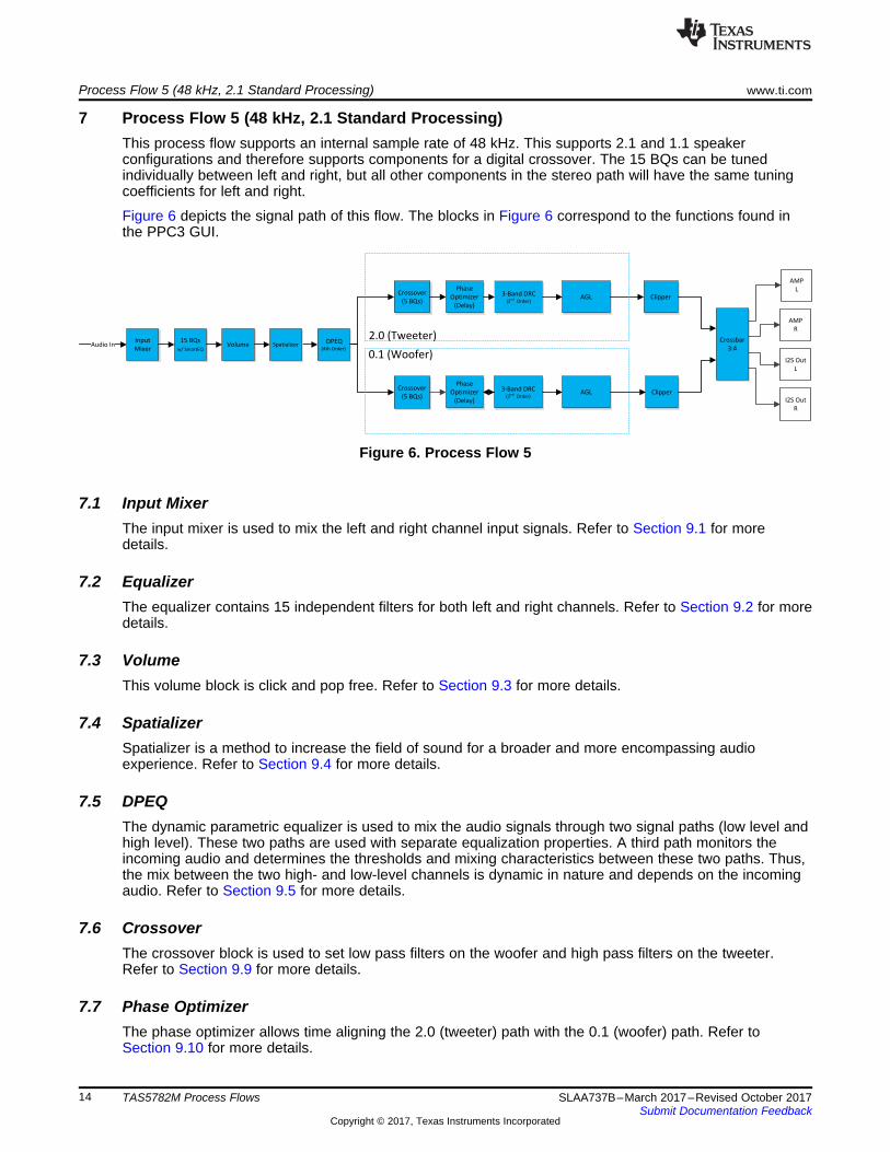
7 Process Flow 5 (48 kHz, 2.1 Standard Processing)This process flow supports an internal sample rate of 48 kHz. This supports 2.1 and 1.1 speakerconfigurations and therefore supports components for a digital crossover. The 15 BQs can be tunedindividually between left and right, but all other components in the stereo path will have the same tuningcoefficients for left and right.
Figure 6 depicts the signal path of this flow. The blocks in Figure 6 correspond to the functions found inthe PPC3 GUI.
Figure 6. Process Flow 5
7.1 Input MixerThe input mixer is used to mix the left and right channel input signals. Refer to Section 9.1 for moredetails.
7.2 EqualizerThe equalizer contains 15 independent filters for both left and right channels. Refer to Section 9.2 for moredetails.
7.3 VolumeThis volume block is click and pop free. Refer to Section 9.3 for more details.
7.4 SpatializerSpatializer is a method to increase the field of sound for a broader and more encompassing audioexperience. Refer to Section 9.4 for more details.
7.5 DPEQThe dynamic parametric equalizer is used to mix the audio signals through two signal paths (low level andhigh level). These two paths are used with separate equalization properties. A third path monitors theincoming audio and determines the thresholds and mixing characteristics between these two paths. Thus,the mix between the two high- and low-level channels is dynamic in nature and depends on the incomingaudio. Refer to Section 9.5 for more details.
7.6 CrossoverThe crossover block is used to set low pass filters on the woofer and high pass filters on the tweeter.Refer to Section 9.9 for more details.
7.7 Phase OptimizerThe phase optimizer allows time aligning the 2.0 (tweeter) path with the 0.1 (woofer) path. Refer toSection 9.10 for more details.

www.ti.com Process Flow 5 (48 kHz, 2.1 Standard Processing)
15SLAA737B–March 2017–Revised October 2017Submit Documentation Feedback
Copyright © 2017, Texas Instruments Incorporated
TAS5782M Process Flows
7.8 3-Band DRCThe 3-Band DRC can be used to automatically control the audio signal amplitude or the dynamic rangewithin specified limits. Refer to Section 9.7 for more details.
7.9 AGLThe AGL can also be used to automatically control the audio signal amplitude or dynamic range withinspecified limits. Refer to Section 9.8 for more details.
7.10 ClipperThe clipper allows the user to programmatically increase the THD by clipping at an operating point earlierthan that defined by the supply rails. Refer to Section 9.11 for more details.
7.11 Output CrossbarThe crossbar provides the end user with a very flexible way to control what finally appears on amplifieroutputs and I2S SDOUT. Refer to Section 9.12 for more details.
7.12 DSP Memory MapRefer to Section A.5 for details.
Audio InInput
Mixer
15 BQs
w/ SmartEQ
Crossover
(5 BQs)
DPEQ(4th Order)
Volume
Crossover
(5 BQs)
Thermal
Limiter
SmartAmp
Spatializer
Clipper
Crossbar
3:40.1(Woofer)
Phase
Optimizer
(Delay)
Phase
Optimizer
(Delay)
Thermal
Limiter
SmartAmp
Excursion
Limiter
SmartAmp
Clipper
2.0(Tweeter)
SmartBass
w/Morphing
AMP
L
AMP
R
I2S Out
L
I2S Out
R
Process Flow 6 (48 kHz, 2.1 SmartAmp Processing) www.ti.com
16 SLAA737B–March 2017–Revised October 2017Submit Documentation Feedback
Copyright © 2017, Texas Instruments Incorporated
TAS5782M Process Flows
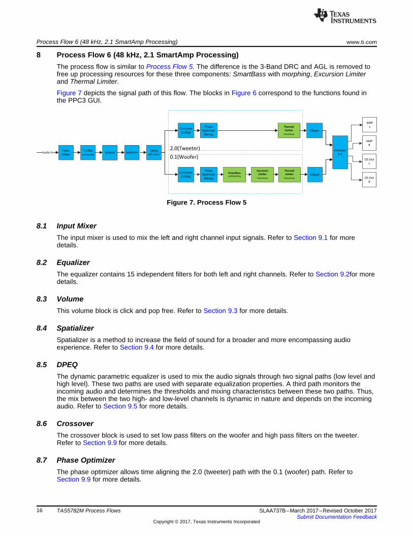
8 Process Flow 6 (48 kHz, 2.1 SmartAmp Processing)The process flow is similar to Process Flow 5. The difference is the 3-Band DRC and AGL is removed tofree up processing resources for these three components: SmartBass with morphing, Excursion Limiterand Thermal Limiter.
Figure 7 depicts the signal path of this flow. The blocks in Figure 6 correspond to the functions found inthe PPC3 GUI.
Figure 7. Process Flow 5
8.1 Input MixerThe input mixer is used to mix the left and right channel input signals. Refer to Section 9.1 for moredetails.
8.2 EqualizerThe equalizer contains 15 independent filters for both left and right channels. Refer to Section 9.2for moredetails.
8.3 VolumeThis volume block is click and pop free. Refer to Section 9.3 for more details.
8.4 SpatializerSpatializer is a method to increase the field of sound for a broader and more encompassing audioexperience. Refer to Section 9.4 for more details.
8.5 DPEQThe dynamic parametric equalizer is used to mix the audio signals through two signal paths (low level andhigh level). These two paths are used with separate equalization properties. A third path monitors theincoming audio and determines the thresholds and mixing characteristics between these two paths. Thus,the mix between the two high- and low-level channels is dynamic in nature and depends on the incomingaudio. Refer to Section 9.5 for more details.
8.6 CrossoverThe crossover block is used to set low pass filters on the woofer and high pass filters on the tweeter.Refer to Section 9.9 for more details.
8.7 Phase OptimizerThe phase optimizer allows time aligning the 2.0 (tweeter) path with the 0.1 (woofer) path. Refer toSection 9.9 for more details.

www.ti.com Process Flow 6 (48 kHz, 2.1 SmartAmp Processing)
17SLAA737B–March 2017–Revised October 2017Submit Documentation Feedback
Copyright © 2017, Texas Instruments Incorporated
TAS5782M Process Flows
8.8 Smart Bass, Excursion Limiter and Thermal LimiterSmart Bass is an intelligent True Bass Alignment algorithm. Smart Bass uses the combination of thespeaker model and a desired target response selected by the user to equalize the speaker in the bassregion. This target response is critical for the sound character and the user can apply the same targetresponse to very different speakers and get the same sound. Refer to Section 10 to 12 for more details.
8.9 ClipperThe clipper allows the user to programmatically increase the THD by clipping at an operating point earlierthan that defined by the supply rails. Refer to Section 9.11 for more details.
8.10 Output CrossbarThe crossbar provides the end user with a very flexible way to control what finally appears on amplifieroutputs and I2S SDOUT. Refer to Section 9.12 for more details.
8.11 DSP Memory MapRefer to Section A.6 for details.

Audio Processing Blocks www.ti.com
18 SLAA737B–March 2017–Revised October 2017Submit Documentation Feedback
Copyright © 2017, Texas Instruments Incorporated
TAS5782M Process Flows
9 Audio Processing Blocks
9.1 Input MixerThe input mixer can be used to mix the left and right channel input signals as shown in Figure 8. The inputmixer has four coefficients, which control the mixing and gains of the input signals.
Figure 8. Input Mixer
The Basic tab (see Figure 9) provides the easiest way for configuration in PPC3 GUI.
Figure 9. Input Mixer (Basic Tab)
1 20 1 2
1 20 1 2
b b Z b ZH(z)
a a Z a Z
- -
- -
+ +
=
+ +
www.ti.com Audio Processing Blocks
19SLAA737B–March 2017–Revised October 2017Submit Documentation Feedback
Copyright © 2017, Texas Instruments Incorporated
TAS5782M Process Flows
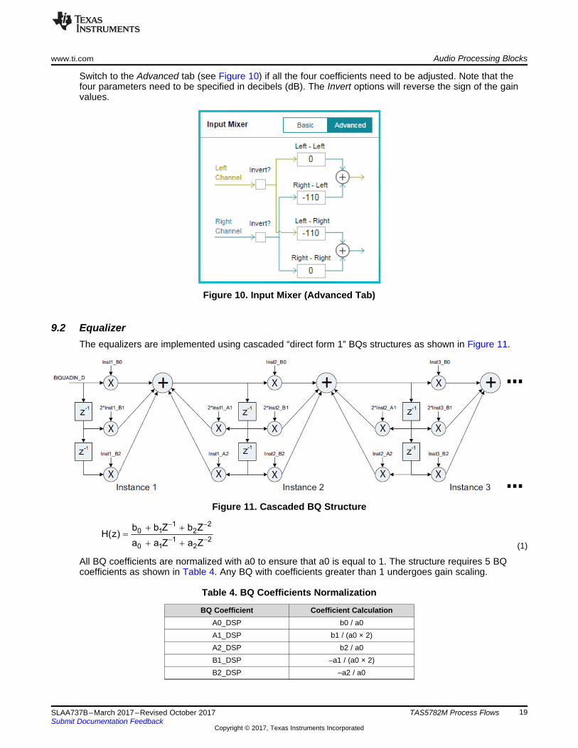
Switch to the Advanced tab (see Figure 10) if all the four coefficients need to be adjusted. Note that thefour parameters need to be specified in decibels (dB). The Invert options will reverse the sign of the gainvalues.
Figure 10. Input Mixer (Advanced Tab)
9.2 EqualizerThe equalizers are implemented using cascaded “direct form 1” BQs structures as shown in Figure 11.
Figure 11. Cascaded BQ Structure
(1)
All BQ coefficients are normalized with a0 to ensure that a0 is equal to 1. The structure requires 5 BQcoefficients as shown in Table 4. Any BQ with coefficients greater than 1 undergoes gain scaling.
Table 4. BQ Coefficients Normalization
BQ Coefficient Coefficient CalculationA0_DSP b0 / a0A1_DSP b1 / (a0 × 2)A2_DSP b2 / a0B1_DSP –a1 / (a0 × 2)B2_DSP –a2 / a0

Audio Processing Blocks www.ti.com
20 SLAA737B–March 2017–Revised October 2017Submit Documentation Feedback
Copyright © 2017, Texas Instruments Incorporated
TAS5782M Process Flows
Depending on the process flow selected, the Equalizer Tuning window may contain 12 or 15 independentfilters for both left and right channels. They are designed for tuning the frequency response of the overallsystem. This is where the bulk of the frequency compensation occurs. Complex tuning shapes can bemade to compensate for deficiencies in speaker response.
As Figure 12 shows, each filter has quite a few different filter types and can be turned on or offindependently. All the changes to these filters are reflected in Figure 12. The composite plot (red) showsthe overall frequency response alteration applied to the incoming digital audio data. Phase, Group Delay,Impulse Response and Pole zero charts are also available on the right side.
Figure 12. Equalizer Tuning Window
The equalizers for left and right channels are ganged by default, but they can be configured independentlyby deselecting the Gang option. For the first two 96-kHz process flows, the Gang option is handledby the GUI but for the two other flows, this is done with a multiplexer, which saves half of thewrites in gang mode.
Volume Volume
td ta
www.ti.com Audio Processing Blocks
21SLAA737B–March 2017–Revised October 2017Submit Documentation Feedback
Copyright © 2017, Texas Instruments Incorporated
TAS5782M Process Flows
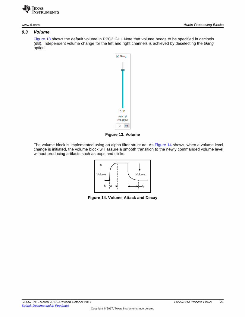
9.3 VolumeFigure 13 shows the default volume in PPC3 GUI. Note that volume needs to be specified in decibels(dB). Independent volume change for the left and right channels is achieved by deselecting the Gangoption.
Figure 13. Volume
The volume block is implemented using an alpha filter structure. As Figure 14 shows, when a volume levelchange is initiated, the volume block will assure a smooth transition to the newly commanded volume levelwithout producing artifacts such as pops and clicks.
Figure 14. Volume Attack and Decay

Audio Processing Blocks www.ti.com
22 SLAA737B–March 2017–Revised October 2017Submit Documentation Feedback
Copyright © 2017, Texas Instruments Incorporated
TAS5782M Process Flows
9.4 SpatializerSpatializer is a method to increase the field of sound for a broader and more encompassing audioexperience. Here, copies of the left and right channels are subtracted from each other. This creates asignal that removes any audio or instrumentation that is shared by both channels. Next a bandpass filtersets the frequency range for which the effect is active. After which, a level control adjusts the strength ofthis channel before being reintroduced back into the original left and right channels.
Figure 15. Spatializer Block Diagram
It is generally not recommend extending the bandpass filter below 300 Hz, since low-frequency contentoften presents itself in both channels. Extending the bandpass too low results in a loss of bass response.Similarly, extending the bandpass too high can create effects similar to reverb which can blur the spatialcues of music.
In the Spatializer Tuning window (see Figure 16), the pass band can be set as well as the Level whichcontrols the level of the effect.
Figure 16. Spatializer Tuning Window

www.ti.com Audio Processing Blocks
23SLAA737B–March 2017–Revised October 2017Submit Documentation Feedback
Copyright © 2017, Texas Instruments Incorporated
TAS5782M Process Flows
For a given piece of end equipment, it may be helpful to create three presets from which to choose. Thisprovides the option of choosing the preferred type of spatializing effect. The three settings can vary boththe HPF, LPF, and effect intensity and their settings stored in the system processor to be updated upon abutton press from the end user.
Three recommended presets are available in the GUI:
Table 5. Recommended Presets Available in the GUI
Preset Frequency Range Level CommentFull 300 Hz to 20 kHz 0.75 Reverberant sounding
Medium 800 Hz to 6 kHz 0.5
Low 4 kHz to 20 kHz 0.25 Works well in systems with a flat frequency response up to 16-18kHz.
9.5 DPEQThe dynamic parametric equalizer mixes the audio signals routed through two paths containing twoBiquads each based upon the signal level detected by the sense path, as shown in Figure 17.
Figure 17. DPEQ

Audio Processing Blocks www.ti.com
24 SLAA737B–March 2017–Revised October 2017Submit Documentation Feedback
Copyright © 2017, Texas Instruments Incorporated
TAS5782M Process Flows
Figure 18. DPEQ Tuning Window
Dynamic Mix ThresholdsThe Energy(ms) simply tells the algorithm for how long to average the samples of audio before itdetermines how it compares to the mixing thresholds. The shorter the time, the faster the mixer reacts tochanges in the input signal level. The longer the time, the slower the mixer reacts to changes in level.
The mixing of the two paths (low level and high level) is controlled by setting the Threshold Low (dB) andThreshold High (dB). When the averaged signal (as set by the Energy) is below the Threshold Low, thedynamic mixer sends all of the audio through the low-level path. When the signal is above the ThresholdHigh, it is sent through the upper-level path. When the signal is between the two, it is mixed together bythe dynamic mixer level.
Energy SenseThe sense path contains 2 configurable Biquads, which can be used to focus the DEQ sensing on aspecific frequency bandwidth.
Low Level EQThe low-level path also has 2 configurable Biquads to establish the EQ curve which the audio is sentthrough when the time average signal is at a low-level. This fully-functional Biquad can be assigned toseveral filter types. This determines frequency response when low-level is active based on the Energyconfiguration and the mixing thresholds.
High Level EQThe high-level path, similar to the low-level path, has 2 Biquads that can set the EQ curve used when thetime averaged input signal is above the upper mixing threshold.

www.ti.com Audio Processing Blocks
25SLAA737B–March 2017–Revised October 2017Submit Documentation Feedback
Copyright © 2017, Texas Instruments Incorporated
TAS5782M Process Flows
9.6 Bass Mono MixerMono Bass Frequency is the cross over point below which the left and right channels are mixed,effectively creating a mono signal below that frequency on both channels. In systems with a commoncabinet for left and right drivers this control ensures against the possibility of a drop in the bass level dueto phase mismatch between the left and right channel signals. For passive radiator systems with 2 activespeakers and 1 passive, the bass mono mixer must be used if a SmartAmp processing is selected.
Figure 19. Bass Mono Mixer
9.7 3-Band DRCThe Dynamic Range Control (DRC) is a feed-forward mechanism that can be used to automatically controlthe audio signal amplitude or the dynamic range within specified limits. The dynamic range control is doneby sensing the audio signal level using an estimate of the alpha filter energy then adjusting the gain basedon the region and slope parameters that are defined. The 3-Band DRC is shown in Figure 20.
Figure 20. 3-Band DRC
The 3-band DRC is comprised of three DRCs that can be spilt into three bands using the BQ at the inputof each band. The DRC in each band is equipped with individual energy, attack, and decay timeconstants. The DRC time constants control the transition time of changes and decisions in the DRC gainduring compression or expansion. The energy, attack, and decay time constants affect the sensitivity levelof the DRC. The shorter the time constant, the more aggressive the DRC response, and vice versa.

Audio Processing Blocks www.ti.com
26 SLAA737B–March 2017–Revised October 2017Submit Documentation Feedback
Copyright © 2017, Texas Instruments Incorporated
TAS5782M Process Flows
Figure 21. DRC Attack and Decay
This DRC can be used for power limiting and signal compression; therefore, it must be tested withmaximum signal levels for the desired application. Use a resistive load for initial testing. However, thespeaker used in the end application must be used for final testing and tweaking.
Figure 22. DRC Tuning Window
The DRC Tuning window consists of three identical windows for low, mid, and high bands. Each has aDRC curve that offers 3 regions of compression. The points on the DRC curve can be dragged anddropped.
Below each DRC plot, parameters such as threshold, offset, and ratio can be manually typed in for eachof the 3 regions. By typing a value and pressing Enter on the keyboard, the DRC curve automaticallyadjusts to the entered parameter.

www.ti.com Audio Processing Blocks
27SLAA737B–March 2017–Revised October 2017Submit Documentation Feedback
Copyright © 2017, Texas Instruments Incorporated
TAS5782M Process Flows
DRC Time ConstantChange time constants by entering new values for each band.
Attack(ms) determines the attack time of the DRC and Decay(ms) determines the release time once thewindowed energy band passes. Energy(ms) controls the time averaging windowing uses to determine theaverage signal energy; therefore, where the incoming signal compares to the set DRC curve. It isbeneficial to have control over the DRC time constant for a given frequency band to avoid beating tonescaused by the DRC attack and the incoming signal frequency.
The mixer gain controls the relative gain of each of the 3 frequency bands after the DRCs when they aremixed together. This is used to attenuate one of the frequency bands relative to the others, if needed.Make note of the sign of the gain coefficients. Since filters affect phase, a phase reversal or a 180degree phase shift may be necessary. Use a negative sign on the coefficient to reverse the phase for thesecond-order LR filter.
CrossoverConfigure the frequency range associated with each of the 3 bands used, where the tuning can takeplace. After tuning, the response is automatically displayed on the right side of the DRC plot. TheCrossover configuration has two tabs. In the Basic tab, only the filter type and cut-off frequencies need tobe determined. Go to the Advanced tab if more parameters need to be adjusted.
9.8 AGLThe Automatic Gain Limiter (AGL) is a feedback mechanism that can be used to automatically control theaudio signal amplitude or dynamic range within specified limits. The automatic gain limiting is done bysensing the audio signal level using an alpha filter energy structure at the output of the AGL then adjustingthe gain based on whether the signal level is above or below the defined threshold. Three decisions madeby the AGL are engage, disengage, or do nothing. The rate at which the AGL engages or disengagesdepends on the attack and release settings respectively.
Figure 23 shows the AGL Tuning window. By default, the AGL is disabled and it can be enabled byclicking the ON/OFF switch on the top right corner.
Figure 23. AGL Tuning Window

Audio Processing Blocks www.ti.com
28 SLAA737B–March 2017–Revised October 2017Submit Documentation Feedback
Copyright © 2017, Texas Instruments Incorporated
TAS5782M Process Flows
Threshold (dB)This parameter sets the threshold at which the compressor will be activated. Lowering the threshold willcause the compression to be activated at lower volume levels. Once the signal exceeds this threshold,compression will be applied.
Alpha(ms)This parameter configures the sharpness of the compression knee of the AGL.
Attack Rate (0–1)This parameter controls how quickly compression will be applied to the signal. Higher values will causethe compressor to respond to signals quickly, while lower values will decrease the response time.
Release Rate (0 – 1)This parameter controls how quickly compression will be removed from the signal as the signal getsquieter. Higher values will cause the compressor to release from signals quickly, while lower values willdecrease the release time.
Figure 24. AGL Attack and Release

www.ti.com Audio Processing Blocks
29SLAA737B–March 2017–Revised October 2017Submit Documentation Feedback
Copyright © 2017, Texas Instruments Incorporated
TAS5782M Process Flows
9.9 CrossoverThe major purpose of a digital crossover is to split the frequencies and then send them off to eachindividual speaker. The crossover is actually a series of filters, which filter out the frequencies that shouldnot go to each speaker. Usually, low pass filters are set on the woofer and high pass filters are set on thetweeter in the crossover.
The plot in Figure 25 in the Crossover Window shows the response of the woofer and tweeter withcrossover filters in place, and the combined response after crossover tuning. Five BQs are available forwoofer and tweeter channel. Fine-tune the filters to get the smoothest response around the crossoverfrequency. Optimally, the crossover sum curve (dark green) is flat and crossover difference curve (lightgreen) has a large dip. If the opposite is seen, it is necessary to invert the phase of BQ1 for the woofer ortweeter.
Figure 25. Crossover Tuning Window

Audio Processing Blocks www.ti.com
30 SLAA737B–March 2017–Revised October 2017Submit Documentation Feedback
Copyright © 2017, Texas Instruments Incorporated
TAS5782M Process Flows
9.10 Phase OptimizerThe phase optimizer allows time aligning the 2.0 (tweeter) path with the 0.1 (woofer) path. Aprogrammable phase delay of up to 16 samples can be achieved for both the tweeter and woofer. The
Phase Delay Tuning Window pops up if the icon on the top right of the Crossover Tuning Window isclicked.
Figure 26. Phase Delay Tuning Window
9.11 ClipperA clipper can be used to digitally achieve the specified THD levels without voltage clipping. It allows usersto achieve the same THD (for example, 10% THD) for different power levels (15 W, 10 W, 5 W) with samePVCC level.
Figure 27. Clipper
Clipper LevelThe clipper level controls the signal level at which clipping occurs.

www.ti.com Audio Processing Blocks
31SLAA737B–March 2017–Revised October 2017Submit Documentation Feedback
Copyright © 2017, Texas Instruments Incorporated
TAS5782M Process Flows
9.12 Output CrossbarThe crossbar provides the end user with a very flexible way to control what finally appears on amplifieroutputs and I2S SDOUT. The Basic tab provides the easiest way for configuration. Go to the Advancedtab if more parameters need to be adjusted. Note that all the parameters need to be specified in decibels(dB).
Figure 28. Output Crossbar (Basic Tab)
Figure 29. Output Crossbar (Advanced Tab)

Smart Amp www.ti.com
32 SLAA737B–March 2017–Revised October 2017Submit Documentation Feedback
Copyright © 2017, Texas Instruments Incorporated
TAS5782M Process Flows
10 Smart AmpConventional hardware-based speaker protection matches the continuous power output of the audioamplifier with the speaker output rating and sometimes incorporates high-pass filtering to prevent over-excursion.
If the maximum output voltage limit of a traditional system is based on the average power of a full-scalesinusoid, there is risk of voice coil overheating if a square wave is provided as an input. This is due to thefact that a square wave has 6 dB higher average power than a sinusoid of the same peak amplitude aswell as having the presence of higher-frequency components. Conservative designs may then have totrade off sound pressure level (SPL) with reliability.
More advanced methods to control load power include the use of limiters and dynamic rangecompressors. These methods can protect the speaker; however, peaks may be clipped or greatly reduced,especially on source material with high peak-to-average ratios (PAR).
PurePath™ Smart Amp replaces hardware-based speaker protection methods with predictive algorithms,speaker characterization tools, and real-time signal monitoring to increase the peak output of the speakerwithout damage.
Figure 30 and Figure 31 are actual song clips comparing the traditional method (left) against Smart Amp(right) to control output power. The dashed lines correspond to the output limit of a traditional system.Note that the average power (Pave) is increased while allowing peaks to cross the output limit.
Figure 30. Audio Clip A, 22-dB Peak-to-Average Ratio Source
Figure 31. Audio Clip B, 9-dB Peak-to-Average Ratio Source

EQ / Volume Smart Bass Protection Amp
Smart Amp Control Algorithm
Automatic bass response
alignment
Smart SOA Smart Sense*3XUH3DWK�
Smart Amp
Thermal,Excursion
*Feedback systems
I/V, Supply, Temperature
Helps keep loudspeaker within SOA
AudioInput
Closed-loop Class-D Amp
Smart EQ
Automatically tunes high
frequencies
www.ti.com Smart Amp
33SLAA737B–March 2017–Revised October 2017Submit Documentation Feedback
Copyright © 2017, Texas Instruments Incorporated
TAS5782M Process Flows
The first implementation step of Smart Amp-based audio solutions is characterizing the speaker with TI’sPurePath Console 3 and the PurePath Learning Board. These are powerful, easy- to-use tools designedspecifically to simplify system-level characterization, tuning, and implementation. The characterizationprocess creates a digital model of the speaker based on thermal, electro-mechanical and acousticparameters.
The output of the characterization process is an initial set of coefficients that define the Safe OperatingArea (SOA) which establishes the boundaries of maximum speaker diaphragm excursion and voice-coiltemperature during operation. If the SOA is set correctly, the audio engineer need not worry aboutspeaker damage during the audio tuning process – depending on how hard the system is pushed – audiomight sound more or less desirable, but speaker safety is ensured if configured properly.
Figure 32. PurePath™ Smart Amp Block Diagram
PurePath Smart Amp technology enables significant sound quality and system reliability improvementswhile reducing component size and cost. The PurePath Console 3 GUI and Learning Board speakercharacterization hardware provide simple configuration of advanced properties fully describing theacoustical, electrical, thermal and reliability capabilities of an audio system and simplifying system-levelcharacterization, tuning, and integration.
10.1 Smart Amp Features
Smart BassBass can easily be extended into any alignmentautomatically. As signal amplitude is increased inthe bass region, Smart Bass automatically morphsthe response to accommodate for larger excursion.

Obtain Hardware and Software
Plan for Development
Obtain Speaker Parameters
End-System Integration
Tune Speaker
Complete!
Smart Amp www.ti.com
34 SLAA737B–March 2017–Revised October 2017Submit Documentation Feedback
Copyright © 2017, Texas Instruments Incorporated
TAS5782M Process Flows
Smart SPLHigh-frequency behavior of the loudspeaker diaphragm cannotbe obtained electrically. Similarly, it is difficult to obtain accuratelow-frequency acoustical measurements without an expensiveanechoic chamber. Smart SPL automatically merges electricaland acoustical measurements to create a full picture of the SPLresponse.
Smart EQAutomatically and efficiently tunes high frequenciesto deliver a flat response or match a target curve inseconds.
Thermal and Excursion ProtectionThe Smart Amp algorithm understands the thermal andexcursion limitations of the speaker. This allows to drive it atpeak levels much louder than conventional amplifiers whilekeeping the voice coil temperature and excursion within thespecified limits. This results in louder audio playback.
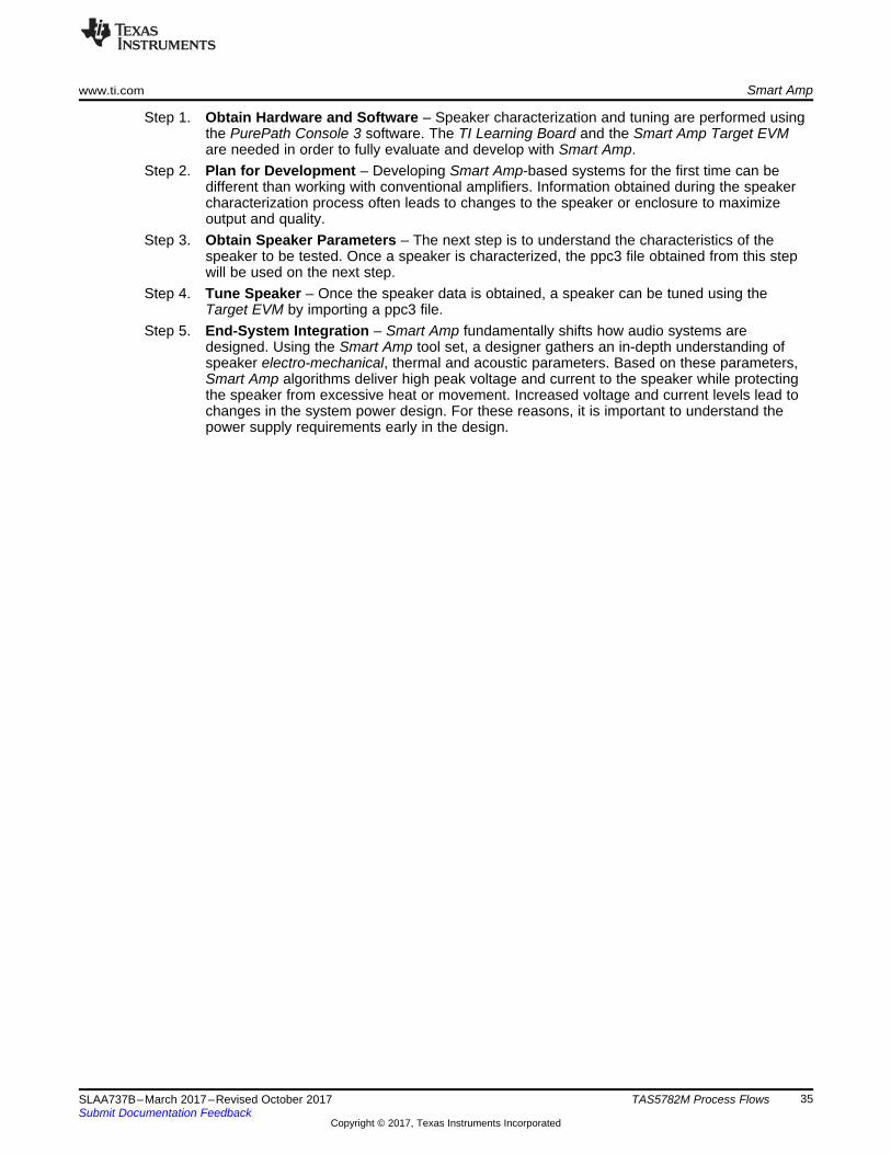
10.2 Smart Amp Development OverviewThe following steps summarize Smart Amp evaluation, planning, characterization, tuning, and integration:
Figure 33. Smart Amp Development Overview
www.ti.com Smart Amp
35SLAA737B–March 2017–Revised October 2017Submit Documentation Feedback
Copyright © 2017, Texas Instruments Incorporated
TAS5782M Process Flows
Step 1. Obtain Hardware and Software – Speaker characterization and tuning are performed usingthe PurePath Console 3 software. The TI Learning Board and the Smart Amp Target EVMare needed in order to fully evaluate and develop with Smart Amp.
Step 2. Plan for Development – Developing Smart Amp-based systems for the first time can bedifferent than working with conventional amplifiers. Information obtained during the speakercharacterization process often leads to changes to the speaker or enclosure to maximizeoutput and quality.
Step 3. Obtain Speaker Parameters – The next step is to understand the characteristics of thespeaker to be tested. Once a speaker is characterized, the ppc3 file obtained from this stepwill be used on the next step.
Step 4. Tune Speaker – Once the speaker data is obtained, a speaker can be tuned using theTarget EVM by importing a ppc3 file.
Step 5. End-System Integration – Smart Amp fundamentally shifts how audio systems aredesigned. Using the Smart Amp tool set, a designer gathers an in-depth understanding ofspeaker electro-mechanical, thermal and acoustic parameters. Based on these parameters,Smart Amp algorithms deliver high peak voltage and current to the speaker while protectingthe speaker from excessive heat or movement. Increased voltage and current levels lead tochanges in the system power design. For these reasons, it is important to understand thepower supply requirements early in the design.
Loudspeaker Characterization www.ti.com
36 SLAA737B–March 2017–Revised October 2017Submit Documentation Feedback
Copyright © 2017, Texas Instruments Incorporated
TAS5782M Process Flows
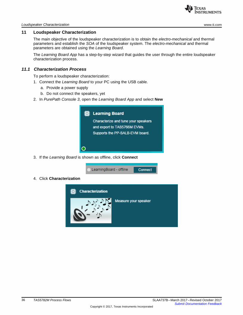
11 Loudspeaker CharacterizationThe main objective of the loudspeaker characterization is to obtain the electro-mechanical and thermalparameters and establish the SOA of the loudspeaker system. The electro-mechanical and thermalparameters are obtained using the Learning Board.
The Learning Board App has a step-by-step wizard that guides the user through the entire loudspeakercharacterization process.
11.1 Characterization ProcessTo perform a loudspeaker characterization:1. Connect the Learning Board to your PC using the USB cable.
a. Provide a power supplyb. Do not connect the speakers, yet
2. In PurePath Console 3, open the Learning Board App and select New
3. If the Learning Board is shown as offline, click Connect
4. Click Characterization

www.ti.com Loudspeaker Characterization
37SLAA737B–March 2017–Revised October 2017Submit Documentation Feedback
Copyright © 2017, Texas Instruments Incorporated
TAS5782M Process Flows
5. Follow the step-by-step wizard until the characterization is complete
6. Once complete, the Characterization Summary page is shown
11.2 Characterization Summary PageThe Characterization Summary page shows the results of the loudspeaker characterization. To verify theloudspeaker plots, use the controls on the top of the graph to select between Modeled SPL and Excursionor Measured Impedance, Temperature, and SPL plots.
Driver and enclosure parameters are also shown as well as the established Safe Operating Area (SOA).
If desired, click the button to redo the characterization. The button will bring back theCharacterization Summary page.
Loudspeaker Characterization www.ti.com
38 SLAA737B–March 2017–Revised October 2017Submit Documentation Feedback
Copyright © 2017, Texas Instruments Incorporated
TAS5782M Process Flows
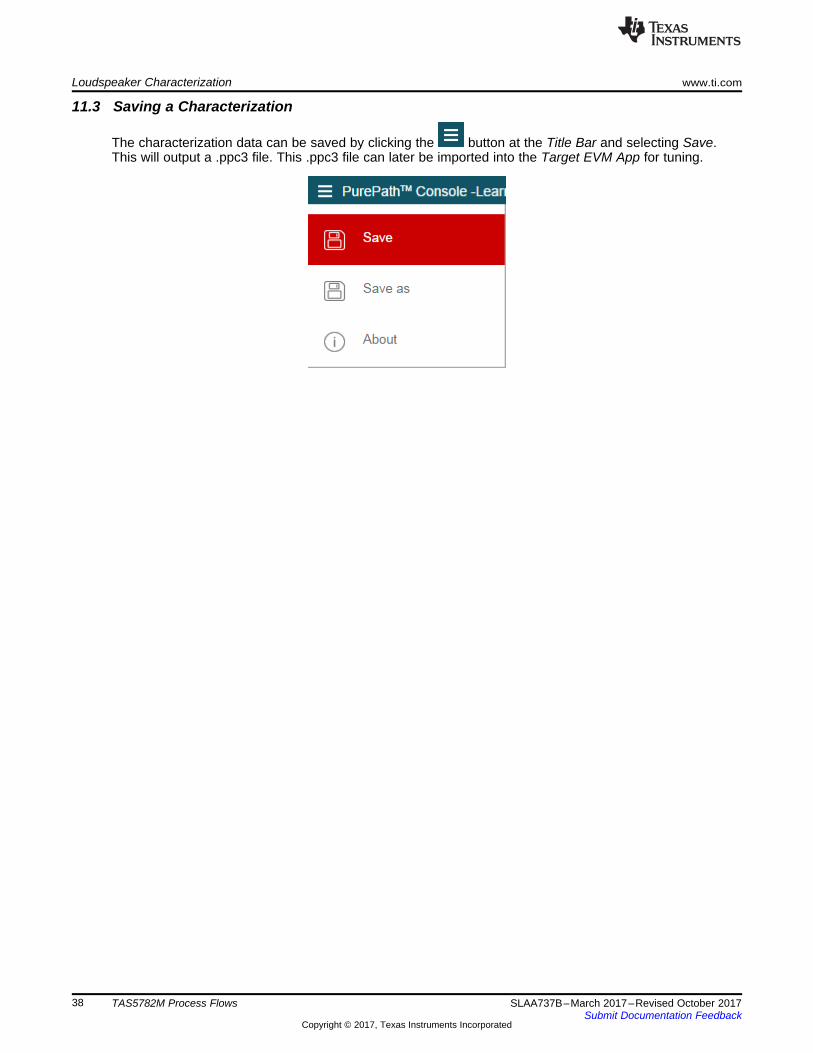
11.3 Saving a Characterization
The characterization data can be saved by clicking the button at the Title Bar and selecting Save.This will output a .ppc3 file. This .ppc3 file can later be imported into the Target EVM App for tuning.

Good?
Tune Bass Enhancement
Tune Morphing Control
Tune Harmonic Bass
Play Music
yes
no
Tune Smart EQ
Done!
Tu
ne
Mo
re
www.ti.com Smart Amp Tuning
39SLAA737B–March 2017–Revised October 2017Submit Documentation Feedback
Copyright © 2017, Texas Instruments Incorporated
TAS5782M Process Flows
12 Smart Amp TuningTuning is a process involving both subjective and methodical approaches. This section provides guidelinesto help establish a baseline to achieve the best possible tuning. The main objectives of the (iterative)audio tuning process, also referred to as ‘voicing’, are:• Improve bass performance using Smart Bass controls by adjusting:
– Bass Enhancement (Section 12.2.1)– Morphing Control (Section 12.2.2)– Harmonic Bass Alignment (Section 12.2.3)
• Improve high frequency response using Equalizer
The Smart Amp Tuning Process is summarized in Figure 34.
Figure 34. Smart Amp Tuning Process
12.1 Tuning PreparationTuning is performed using the TAS5782MEVM:1. Connect the TAS5782MEVM to your PC using the USB cable.
• Provide a power supply (matching the one to be used in the final system)• Connect the loudspeaker

Smart Amp Tuning www.ti.com
40 SLAA737B–March 2017–Revised October 2017Submit Documentation Feedback
Copyright © 2017, Texas Instruments Incorporated
TAS5782M Process Flows
2. In PurePath Console 3, open the TAS5782 App.
3. If the board is shown as offline, click Connect.
4. Click Tuning and Audio Processing.
5. Select a SmartAmp Processing (48k or 96k).
6. Import the characterization data that was obtained during the Characterization process by clicking theImport button.
www.ti.com Smart Amp Tuning
41SLAA737B–March 2017–Revised October 2017Submit Documentation Feedback
Copyright © 2017, Texas Instruments Incorporated
TAS5782M Process Flows
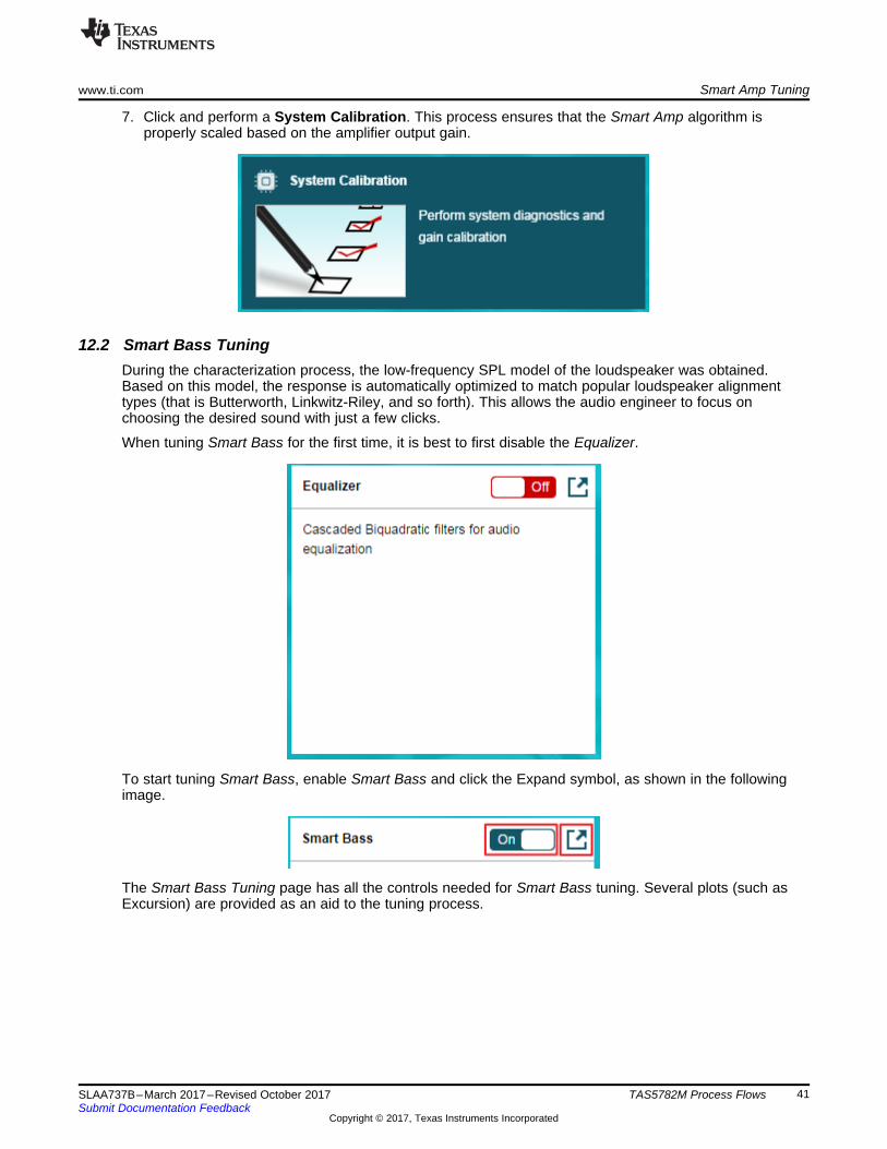
7. Click and perform a System Calibration. This process ensures that the Smart Amp algorithm isproperly scaled based on the amplifier output gain.
12.2 Smart Bass TuningDuring the characterization process, the low-frequency SPL model of the loudspeaker was obtained.Based on this model, the response is automatically optimized to match popular loudspeaker alignmenttypes (that is Butterworth, Linkwitz-Riley, and so forth). This allows the audio engineer to focus onchoosing the desired sound with just a few clicks.
When tuning Smart Bass for the first time, it is best to first disable the Equalizer.
To start tuning Smart Bass, enable Smart Bass and click the Expand symbol, as shown in the followingimage.
The Smart Bass Tuning page has all the controls needed for Smart Bass tuning. Several plots (such asExcursion) are provided as an aid to the tuning process.
Good?
Set Corner Frequency
Set Alignment Order (Slope)
Set Alignment Type
Listening Testat Low Volume Levels(for Example, í30 dB)
yes
no
Smart Amp Tuning www.ti.com
42 SLAA737B–March 2017–Revised October 2017Submit Documentation Feedback
Copyright © 2017, Texas Instruments Incorporated
TAS5782M Process Flows
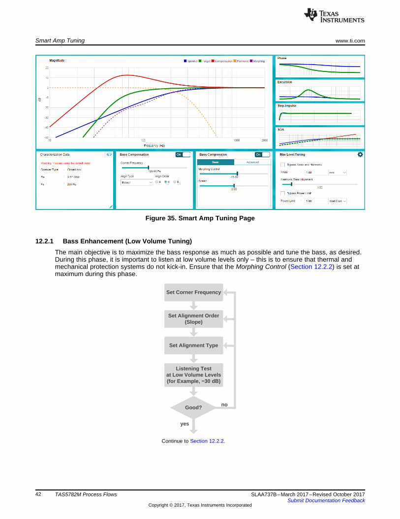
Figure 35. Smart Amp Tuning Page
12.2.1 Bass Enhancement (Low Volume Tuning)The main objective is to maximize the bass response as much as possible and tune the bass, as desired.During this phase, it is important to listen at low volume levels only – this is to ensure that thermal andmechanical protection systems do not kick-in. Ensure that the Morphing Control (Section 12.2.2) is set atmaximum during this phase.
spacerspacerspacerspacerspacerspacererContinue to Section 12.2.2.

www.ti.com Smart Amp Tuning
43SLAA737B–March 2017–Revised October 2017Submit Documentation Feedback
Copyright © 2017, Texas Instruments Incorporated
TAS5782M Process Flows
Table 6. Bass Enhancement Parameters
Field DescriptionCorner Frequency –3-dB point of the target response. Smaller speaker drivers should use higher corner frequency.Order (Slope) Determines the sharpness of the roll-off towards lower frequencies. For lower corner frequency, choose
higher order.Type Selects the alignment type
Corner FrequencyThe Corner Frequency indicates the –3-dB point of a flat response target (indicated by the green curve inthe following image). Selecting a proper Corner Frequency is important for the overall performance of thespeaker system. If the cutoff is set too high, the speaker will have limited bass response. If set too low,energy will be wasted trying to drive frequencies that the speaker will not be able to reproduce and theexcursion protection system will be overly active.
TI recommends doing a series of listening tests while adjusting settings.• Adjust Corner Frequency while watching the compensation (red curve) in the response plot window.• Targeting between a 10- to 20-dB compensation (red curve) often provides the best results.• Do not exceed the 20-dB line (at least initially).
Alignment Order and TypeThe Order and Type determine the bass roll-off. In other words, it determines what occurs below thecorner frequency.
A high-order roll-off cuts bass faster, saving power and limiting speaker excursion that will not producemuch SPL. Likewise, Type has significant influence on the SPL and energy below the corner frequency.• Select a higher order if the speaker handles excursion poorly.• Select a lower order to leave small amounts of low-frequency content in the signal.• Butterworth is suitable for most applications. For ported or passive radiator systems that can reproduce
60–80 Hz, a Chebyshev alignment works well.

Set Morphing to í15 dB
Listening Test(Adjust Input
Volume Up/Down)
yes
no
Artifacts?yes Set Morphing
Higher
Set Morphing Lower
Re-Tune Bass Enhancement
No Bass?
Good?
yes
no
no
Smart Amp Tuning www.ti.com
44 SLAA737B–March 2017–Revised October 2017Submit Documentation Feedback
Copyright © 2017, Texas Instruments Incorporated
TAS5782M Process Flows
12.2.2 Morphing Control (Mid- to High-Volume Tuning)
Morphing determines the headroom dependentbalance between Bass Enhancement andHarmonic Bass Alignment. As excursion andthermal headroom drops with increase in musicloudness, the Morphing feature gradually anddynamically reduces bass.
From Section 12.2.1
Continue to Section 12.2.3
Depending on Speed and Harmonic Alignmentsettings, some residue of bass harmonics mightremain in the frequency spectrum creating apsychoacoustic bass enhancement effect.• Audible artifacts indicate too high Morphing
setting• Little but clean bass could indicate that the
Morphing setting is too low
NOTE: This is an iterative process! It is important to listen to different types of music and at severalvolume settings (listening levels).
Morphing Speed (Optional)The Morphing Speed control determines the aggressiveness on which the Smart Amp algorithm adapts toa change of headroom.
Speakers react very differently to morphing speed and unfortunately there is no universal guideline forhow to tune this for the best setting. TI recommends experimenting with several settings. This setting mayalso be left at the default value (0).• Listen to different music types at moderate to high volume levels• Listen for audible artifacts such as:
– Bass region: distortion, especially with high transients (such as a kick drum)– Mid/high range: distortion, modulation artifacts
Listening Testat High Volume (for
Example, 0 dB)
Artifacts?yes Decrease Peak
Excursion Limit in SOA
Increase Peak Excursion Limit
in SOA
Excursion Headroom
yes
no
no Caution!Complete!
Set Morphing 5 to 15 dB Higher Than in Section 10.2.2
Listening TestAt High Volume (for Example, í10 dB)
Artifacts?yes Adjust
Harmonic Bass Alignment
no
Reset Morphing Back to the Original Value From
Section 10.2.2
yes
noGood?
www.ti.com Smart Amp Tuning
45SLAA737B–March 2017–Revised October 2017Submit Documentation Feedback
Copyright © 2017, Texas Instruments Incorporated
TAS5782M Process Flows
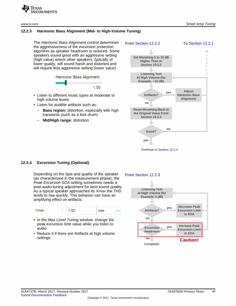
12.2.3 Harmonic Bass Alignment (Mid- to High-Volume Tuning)
The Harmonic Bass Alignment control determinesthe aggressiveness of the excursion protectionalgorithm as speaker headroom is reduced. Somespeakers sound great with an aggressive setting(high value) where other speakers, typically oflower quality, will sound harsh and distorted andwill require less aggressive setting (lower value).
• Listen to different music types at moderate tohigh volume levels
• Listen for audible artifacts such as:– Bass region: distortion, especially with high
transients (such as a kick drum)– Mid/High range: distortion
From Section 12.2.2spacerspacerTo Section 12.2.1
Continue to Section 12.2.4
12.2.4 Excursion Tuning (Optional)
Depending on the type and quality of the speaker(as characterized in the measurement phase), thePeak Excursion SOA setting sometimes needs apost-audio-tuning adjustment for best sound quality.As a typical speaker approaches its Xmax the THDtends to rise quickly. This behavior can have anamplifying effect on artifacts.
• In the Max Level Tuning window, change thepeak excursion limit value while you listen toaudio.
• Reduce it if there are Artifacts at high volumesettings.
From Section 12.2.3
46 SLAA737B–March 2017–Revised October 2017Submit Documentation Feedback
Copyright © 2017, Texas Instruments Incorporated
TAS5782M Process Flows
Appendix ASLAA737B–March 2017–Revised October 2017
DSP Memory Map
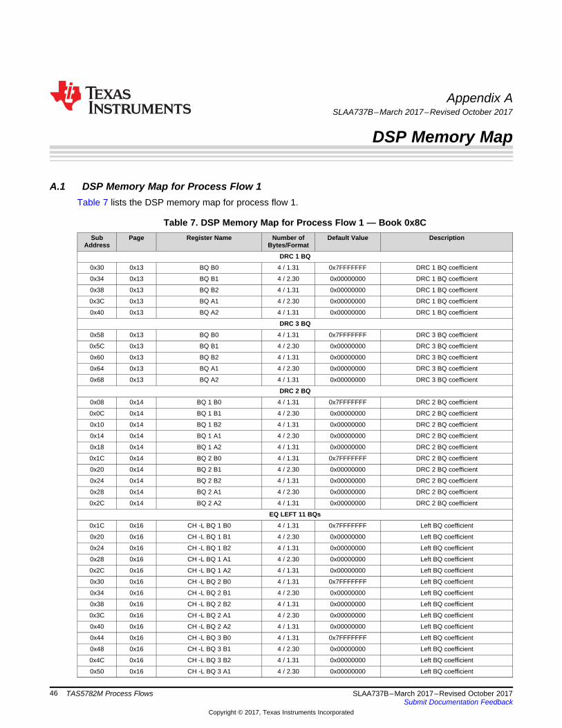
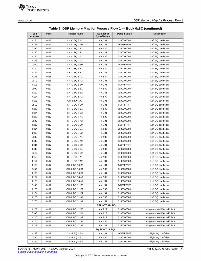
A.1 DSP Memory Map for Process Flow 1Table 7 lists the DSP memory map for process flow 1.
Table 7. DSP Memory Map for Process Flow 1 — Book 0x8CSub
AddressPage Register Name Number of
Bytes/FormatDefault Value Description
DRC 1 BQ
0x30 0x13 BQ B0 4 / 1.31 0x7FFFFFFF DRC 1 BQ coefficient
0x34 0x13 BQ B1 4 / 2.30 0x00000000 DRC 1 BQ coefficient
0x38 0x13 BQ B2 4 / 1.31 0x00000000 DRC 1 BQ coefficient
0x3C 0x13 BQ A1 4 / 2.30 0x00000000 DRC 1 BQ coefficient
0x40 0x13 BQ A2 4 / 1.31 0x00000000 DRC 1 BQ coefficient
DRC 3 BQ
0x58 0x13 BQ B0 4 / 1.31 0x7FFFFFFF DRC 3 BQ coefficient
0x5C 0x13 BQ B1 4 / 2.30 0x00000000 DRC 3 BQ coefficient
0x60 0x13 BQ B2 4 / 1.31 0x00000000 DRC 3 BQ coefficient
0x64 0x13 BQ A1 4 / 2.30 0x00000000 DRC 3 BQ coefficient
0x68 0x13 BQ A2 4 / 1.31 0x00000000 DRC 3 BQ coefficient
DRC 2 BQ
0x08 0x14 BQ 1 B0 4 / 1.31 0x7FFFFFFF DRC 2 BQ coefficient
0x0C 0x14 BQ 1 B1 4 / 2.30 0x00000000 DRC 2 BQ coefficient
0x10 0x14 BQ 1 B2 4 / 1.31 0x00000000 DRC 2 BQ coefficient
0x14 0x14 BQ 1 A1 4 / 2.30 0x00000000 DRC 2 BQ coefficient
0x18 0x14 BQ 1 A2 4 / 1.31 0x00000000 DRC 2 BQ coefficient
0x1C 0x14 BQ 2 B0 4 / 1.31 0x7FFFFFFF DRC 2 BQ coefficient
0x20 0x14 BQ 2 B1 4 / 2.30 0x00000000 DRC 2 BQ coefficient
0x24 0x14 BQ 2 B2 4 / 1.31 0x00000000 DRC 2 BQ coefficient
0x28 0x14 BQ 2 A1 4 / 2.30 0x00000000 DRC 2 BQ coefficient
0x2C 0x14 BQ 2 A2 4 / 1.31 0x00000000 DRC 2 BQ coefficient
EQ LEFT 11 BQs
0x1C 0x16 CH -L BQ 1 B0 4 / 1.31 0x7FFFFFFF Left BQ coefficient
0x20 0x16 CH -L BQ 1 B1 4 / 2.30 0x00000000 Left BQ coefficient
0x24 0x16 CH -L BQ 1 B2 4 / 1.31 0x00000000 Left BQ coefficient
0x28 0x16 CH -L BQ 1 A1 4 / 2.30 0x00000000 Left BQ coefficient
0x2C 0x16 CH -L BQ 1 A2 4 / 1.31 0x00000000 Left BQ coefficient
0x30 0x16 CH -L BQ 2 B0 4 / 1.31 0x7FFFFFFF Left BQ coefficient
0x34 0x16 CH -L BQ 2 B1 4 / 2.30 0x00000000 Left BQ coefficient
0x38 0x16 CH -L BQ 2 B2 4 / 1.31 0x00000000 Left BQ coefficient
0x3C 0x16 CH -L BQ 2 A1 4 / 2.30 0x00000000 Left BQ coefficient
0x40 0x16 CH -L BQ 2 A2 4 / 1.31 0x00000000 Left BQ coefficient
0x44 0x16 CH -L BQ 3 B0 4 / 1.31 0x7FFFFFFF Left BQ coefficient
0x48 0x16 CH -L BQ 3 B1 4 / 2.30 0x00000000 Left BQ coefficient
0x4C 0x16 CH -L BQ 3 B2 4 / 1.31 0x00000000 Left BQ coefficient
0x50 0x16 CH -L BQ 3 A1 4 / 2.30 0x00000000 Left BQ coefficient
www.ti.com DSP Memory Map for Process Flow 1
47SLAA737B–March 2017–Revised October 2017Submit Documentation Feedback
Copyright © 2017, Texas Instruments Incorporated
TAS5782M Process Flows
Table 7. DSP Memory Map for Process Flow 1 — Book 0x8C (continued)Sub
AddressPage Register Name Number of
Bytes/FormatDefault Value Description
0x54 0x16 CH -L BQ 3 A2 4 / 1.31 0x00000000 Left BQ coefficient
0x58 0x16 CH -L BQ 4 B0 4 / 1.31 0x7FFFFFFF Left BQ coefficient
0x5C 0x16 CH -L BQ 4 B1 4 / 2.30 0x00000000 Left BQ coefficient
0x60 0x16 CH -L BQ 4 B2 4 / 1.31 0x00000000 Left BQ coefficient
0x64 0x16 CH -L BQ 4 A1 4 / 2.30 0x00000000 Left BQ coefficient
0x68 0x16 CH -L BQ 4 A2 4 / 1.31 0x00000000 Left BQ coefficient
0x6C 0x16 CH -L BQ 5 B0 4 / 1.31 0x7FFFFFFF Left BQ coefficient
0x70 0x16 CH -L BQ 5 B1 4 / 2.30 0x00000000 Left BQ coefficient
0x74 0x16 CH -L BQ 5 B2 4 / 1.31 0x00000000 Left BQ coefficient
0x78 0x16 CH -L BQ 5 A1 4 / 2.30 0x00000000 Left BQ coefficient
0x7C 0x16 CH -L BQ 5 A2 4 / 1.31 0x00000000 Left BQ coefficient
0x08 0x17 CH -L BQ 6 B0 4 / 1.31 0x7FFFFFFF Left BQ coefficient
0x0C 0x17 CH -L BQ 6 B1 4 / 2.30 0x00000000 Left BQ coefficient
0x10 0x17 CH -L BQ 6 B2 4 / 1.31 0x00000000 Left BQ coefficient
0x14 0x17 CH -L BQ 6 A1 4 / 2.30 0x00000000 Left BQ coefficient
0x18 0x17 CH -LBQ 6 A2 4 / 1.31 0x00000000 Left BQ coefficient
0x1C 0x17 CH -L BQ 7 B0 4 / 1.31 0x7FFFFFFF Left BQ coefficient
0x20 0x17 CH -L BQ 7 B1 4 / 2.30 0x00000000 Left BQ coefficient
0x24 0x17 CH -L BQ 7 B2 4 / 1.31 0x00000000 Left BQ coefficient
0x28 0x17 CH -L BQ 7 A1 4 / 2.30 0x00000000 Left BQ coefficient
0x2C 0x17 CH -L BQ 7 A2 4 / 1.31 0x00000000 Left BQ coefficient
0x30 0x17 CH -L BQ 8 B0 4 / 1.31 0x7FFFFFFF Left BQ coefficient
0x34 0x17 CH -L BQ 8 B1 4 / 2.30 0x00000000 Left BQ coefficient
0x38 0x17 CH -L BQ 8 B2 4 / 1.31 0x00000000 Left BQ coefficient
0x3C 0x17 CH -L BQ 8 A1 4 / 2.30 0x00000000 Left BQ coefficient
0x40 0x17 CH -L BQ 8 A2 4 / 1.31 0x00000000 Left BQ coefficient
0x44 0x17 CH -L BQ 9 B0 4 / 1.31 0x7FFFFFFF Left BQ coefficient
0x48 0x17 CH -L BQ 9 B1 4 / 2.30 0x00000000 Left BQ coefficient
0x4C 0x17 CH -L BQ 9 B2 4 / 1.31 0x00000000 Left BQ coefficient
0x50 0x17 CH -L BQ 9 A1 4 / 2.30 0x00000000 Left BQ coefficient
0x54 0x17 CH -L BQ 9 A2 4 / 1.31 0x00000000 Left BQ coefficient
0x58 0x17 CH -L BQ 10 B0 4 / 1.31 0x7FFFFFFF Left BQ coefficient
0x5C 0x17 CH -L BQ 10 B1 4 / 2.30 0x00000000 Left BQ coefficient
0x60 0x17 CH -L BQ 10 B2 4 / 1.31 0x00000000 Left BQ coefficient
0x64 0x17 CH -L BQ 10 A1 4 / 2.30 0x00000000 Left BQ coefficient
0x68 0x17 CH -L BQ 10 A2 4 / 1.31 0x00000000 Left BQ coefficient
0x6C 0x17 CH -L BQ 11 B0 4 / 1.31 0x7FFFFFFF Left BQ coefficient
0x70 0x17 CH -L BQ 11 B1 4 / 2.30 0x00000000 Left BQ coefficient
0x74 0x17 CH -L BQ 11 B2 4 / 1.31 0x00000000 Left BQ coefficient
0x78 0x17 CH -L BQ 11 A1 4 / 2.30 0x00000000 Left BQ coefficient
0x7C 0x17 CH -L BQ 11 A2 4 / 1.31 0x00000000 Left BQ coefficient
LEFT INTGAIN BQ
0x08 0x18 CH -L BQ 12 B0 4 / 5.27 0x08000000 Left gain scale BQ coefficient
0x0C 0x18 CH -L BQ 12 B1 4 / 6.26 0x00000000 Left gain scale BQ coefficient
0x10 0x18 CH -L BQ 12 B2 4 / 5.27 0x00000000 Left gain scale BQ coefficient
0x14 0x18 CH -L BQ 12 A1 4 / 2.30 0x00000000 Left gain scale BQ coefficient
0x18 0x18 CH -L BQ 12 A2 4 / 1.31 0x00000000 Left gain scale BQ coefficient
EQ RIGHT 11 BQs
0x58 0x18 CH -R BQ 1 B0 4 / 1.31 0x7FFFFFFF Right BQ coefficient
0x5C 0x18 CH -R BQ 1 B1 4 / 2.30 0x00000000 Right BQ coefficient
0x60 0x18 CH -R BQ 1 B2 4 / 1.31 0x00000000 Right BQ coefficient
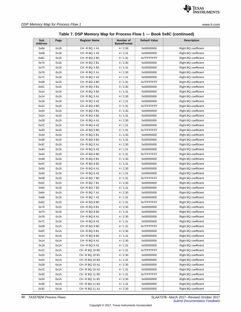
DSP Memory Map for Process Flow 1 www.ti.com
48 SLAA737B–March 2017–Revised October 2017Submit Documentation Feedback
Copyright © 2017, Texas Instruments Incorporated
TAS5782M Process Flows
Table 7. DSP Memory Map for Process Flow 1 — Book 0x8C (continued)Sub
AddressPage Register Name Number of
Bytes/FormatDefault Value Description
0x64 0x18 CH -R BQ 1 A1 4 / 2.30 0x00000000 Right BQ coefficient
0x68 0x18 CH -R BQ 1 A2 4 / 1.31 0x00000000 Right BQ coefficient
0x6C 0x18 CH -R BQ 2 B0 4 / 1.31 0x7FFFFFFF Right BQ coefficient
0x70 0x18 CH -R BQ 2 B1 4 / 2.30 0x00000000 Right BQ coefficient
0x74 0x18 CH -R BQ 2 B2 4 / 1.31 0x00000000 Right BQ coefficient
0x78 0x18 CH -R BQ 2 A1 4 / 2.30 0x00000000 Right BQ coefficient
0x7C 0x18 CH -R BQ 2 A2 4 / 1.31 0x00000000 Right BQ coefficient
0x08 0x19 CH -R BQ 3 B0 4 / 1.31 0x7FFFFFFF Right BQ coefficient
0x0C 0x19 CH -R BQ 3 B1 4 / 2.30 0x00000000 Right BQ coefficient
0x10 0x19 CH -R BQ 3 B2 4 / 1.31 0x00000000 Right BQ coefficient
0x14 0x19 CH -R BQ 3 A1 4 / 2.30 0x00000000 Right BQ coefficient
0x18 0x19 CH -R BQ 3 A2 4 / 1.31 0x00000000 Right BQ coefficient
0x1C 0x19 CH -R BQ 4 B0 4 / 1.31 0x7FFFFFFF Right BQ coefficient
0x20 0x19 CH -R BQ 4 B1 4 / 2.30 0x00000000 Right BQ coefficient
0x24 0x19 CH -R BQ 4 B2 4 / 1.31 0x00000000 Right BQ coefficient
0x28 0x19 CH -R BQ 4 A1 4 / 2.30 0x00000000 Right BQ coefficient
0x2C 0x19 CH -R BQ 4 A2 4 / 1.31 0x00000000 Right BQ coefficient
0x30 0x19 CH -R BQ 5 B0 4 / 1.31 0x7FFFFFFF Right BQ coefficient
0x34 0x19 CH -R BQ 5 B1 4 / 2.30 0x00000000 Right BQ coefficient
0x38 0x19 CH -R BQ 5 B2 4 / 1.31 0x00000000 Right BQ coefficient
0x3C 0x19 CH -R BQ 5 A1 4 / 2.30 0x00000000 Right BQ coefficient
0x40 0x19 CH -R BQ 5 A2 4 / 1.31 0x00000000 Right BQ coefficient
0x44 0x19 CH -R BQ 6 B0 4 / 1.31 0x7FFFFFFF Right BQ coefficient
0x48 0x19 CH -R BQ 6 B1 4 / 2.30 0x00000000 Right BQ coefficient
0x4C 0x19 CH -R BQ 6 B2 4 / 1.31 0x00000000 Right BQ coefficient
0x50 0x19 CH -R BQ 6 A1 4 / 2.30 0x00000000 Right BQ coefficient
0x54 0x19 CH -R BQ 6 A2 4 / 1.31 0x00000000 Right BQ coefficient
0x58 0x19 CH -R BQ 7 B0 4 / 1.31 0x7FFFFFFF Right BQ coefficient
0x5C 0x19 CH -R BQ 7 B1 4 / 2.30 0x00000000 Right BQ coefficient
0x60 0x19 CH -R BQ 7 B2 4 / 1.31 0x00000000 Right BQ coefficient
0x64 0x19 CH -R BQ 7 A1 4 / 2.30 0x00000000 Right BQ coefficient
0x68 0x19 CH -R BQ 7 A2 4 / 1.31 0x00000000 Right BQ coefficient
0x6C 0x19 CH -R BQ 8 B0 4 / 1.31 0x7FFFFFFF Right BQ coefficient
0x70 0x19 CH -R BQ 8 B1 4 / 2.30 0x00000000 Right BQ coefficient
0x74 0x19 CH -R BQ 8 B2 4 / 1.31 0x00000000 Right BQ coefficient
0x78 0x19 CH -R BQ 8 A1 4 / 2.30 0x00000000 Right BQ coefficient
0x7C 0x19 CH -R BQ 8 A2 4 / 1.31 0x00000000 Right BQ coefficient
0x08 0x1A CH -R BQ 9 B0 4 / 1.31 0x7FFFFFFF Right BQ coefficient
0x0C 0x1A CH -R BQ 9 B1 4 / 2.30 0x00000000 Right BQ coefficient
0x10 0x1A CH -R BQ 9 B2 4 / 1.31 0x00000000 Right BQ coefficient
0x14 0x1A CH -R BQ 9 A1 4 / 2.30 0x00000000 Right BQ coefficient
0x18 0x1A CH -R BQ 9 A2 4 / 1.31 0x00000000 Right BQ coefficient
0x1C 0x1A CH -R BQ 10 B0 4 / 1.31 0x7FFFFFFF Right BQ coefficient
0x20 0x1A CH -R BQ 10 B1 4 / 2.30 0x00000000 Right BQ coefficient
0x24 0x1A CH -R BQ 10 B2 4 / 1.31 0x00000000 Right BQ coefficient
0x28 0x1A CH -R BQ 10 A1 4 / 2.30 0x00000000 Right BQ coefficient
0x2C 0x1A CH -R BQ 10 A2 4 / 1.31 0x00000000 Right BQ coefficient
0x30 0x1A CH -R BQ 11 B0 4 / 1.31 0x7FFFFFFF Right BQ coefficient
0x34 0x1A CH -R BQ 11 B1 4 / 2.30 0x00000000 Right BQ coefficient
0x38 0x1A CH -R BQ 11 B2 4 / 1.31 0x00000000 Right BQ coefficient
0x3C 0x1A CH -R BQ 11 A1 4 / 2.30 0x00000000 Right BQ coefficient
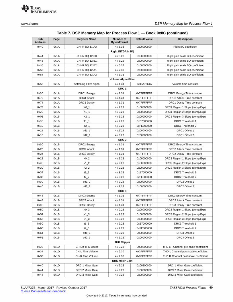
www.ti.com DSP Memory Map for Process Flow 1
49SLAA737B–March 2017–Revised October 2017Submit Documentation Feedback
Copyright © 2017, Texas Instruments Incorporated
TAS5782M Process Flows
Table 7. DSP Memory Map for Process Flow 1 — Book 0x8C (continued)Sub
AddressPage Register Name Number of
Bytes/FormatDefault Value Description
0x40 0x1A CH -R BQ 11 A2 4 / 1.31 0x00000000 Right BQ coefficient
Right INTGAIN BQ
0x44 0x1A CH -R BQ 12 B0 4 / 5.27 0x08000000 Right gain scale BQ coefficient
0x48 0x1A CH -R BQ 12 B1 4 / 6.26 0x00000000 Right gain scale BQ coefficient
0x4C 0x1A CH -R BQ 12 B2 4 / 5.27 0x00000000 Right gain scale BQ coefficient
0x50 0x1A CH -R BQ 12 A1 4 / 2.30 0x00000000 Right gain scale BQ coefficient
0x54 0x1A CH -R BQ 12 A2 4 / 1.31 0x00000000 Right gain scale BQ coefficient
Volume Alpha Filter
0x58 0x1A Softening Filter Alpha 4 / 1.31 0x00A7264A Volume time constant
DRC 1
0x6C 0x1A DRC1 Energy 4 / 1.31 0x7FFFFFFF DRC1 Energy Time constant
0x70 0x1A DRC1 Attack 4 / 1.31 0x7FFFFFFF DRC1 Attack Time constant
0x74 0x1A DRC1 Decay 4 / 1.31 0x7FFFFFFF DRC1 Decay Time constant
0x78 0x1A K0_1 4 / 9.23 0x00000000 DRC1 Region 1 Slope (comp/Exp)
0x7C 0x1A K1_1 4 / 9.23 0x00000000 DRC1 Region 2 Slope (comp/Exp)
0x08 0x1B K2_1 4 / 9.23 0x00000000 DRC1 Region 3 Slope (comp/Exp)
0x0C 0x1B T1_1 4 / 9.23 0xE7000000 DRC1 Threshold 1
0x10 0x1B T2_1 4 / 9.23 0xFE800000 DRC1 Threshold 2
0x14 0x1B off1_1 4 / 9.23 0x00000000 DRC1 Offset 1
0x18 0x1B off2_1 4 / 9.23 0x00000000 DRC1 Offset 2
DRC 2
0x1C 0x1B DRC2 Energy 4 / 1.31 0x7FFFFFFF DRC2 Energy Time constant
0x20 0x1B DRC2 Attack 4 / 1.31 0x7FFFFFFF DRC2 Attack Time constant
0x24 0x1B DRC2 Decay 4 / 1.31 0x7FFFFFFF DRC2 Decay Time constant
0x28 0x1B k0_2 4 / 9.23 0x00000000 DRC2 Region 1 Slope (comp/Exp)
0x2C 0x1B k1_2 4 / 9.23 0x00000000 DRC2 Region 2 Slope (comp/Exp)
0x30 0x1B k2_2 4 / 9.23 0x00000000 DRC2 Region 3 Slope (comp/Exp)
0x34 0x1B t1_2 4 / 9.23 0xE7000000 DRC2 Threshold 1
0x38 0x1B t2_2 4 / 9.23 0xFE800000 DRC2 Threshold 2
0x3C 0x1B off1_2 4 / 9.23 0x00000000 DRC2 Offset 1
0x40 0x1B off2_2 4 / 9.23 0x00000000 DRC2 Offset 2
DRC 3
0x44 0x1B DRC3 Energy 4 / 1.31 0x7FFFFFFF DRC3 Energy Time constant
0x48 0x1B DRC3 Attack 4 / 1.31 0x7FFFFFFF DRC3 Attack Time constant
0x4C 0x1B DRC3 Decay 4 / 1.31 0x7FFFFFFF DRC3 Decay Time constant
0x50 0x1B k0_3 4 / 9.23 0x00000000 DRC3 Region 1 Slope (comp/Exp)
0x54 0x1B k1_3 4 / 9.23 0x00000000 DRC3 Region 2 Slope (comp/Exp)
0x58 0x1B k1_3 4 / 9.23 0x00000000 DRC3 Region 3 Slope (comp/Exp)
0x5C 0x1B t1_3 4 / 9.23 0xE7000000 DRC3 Threshold 1
0x60 0x1B t2_3 4 / 9.23 0xFE800000 DRC3 Threshold 2
0x64 0x1B off1_3 4 / 9.23 0x00000000 DRC3 Offset 1
0x68 0x1B off2_3 4 / 9.23 0x00000000 DRC3 Offset 2
THD Clipper
0x2C 0x1D CH-LR THD Boost 4 / 9.23 0x00800000 THD LR Channel pre-scale coefficient
0x34 0x1D CH-L Fine Volume 4 / 2.30 0x3FFFFFFF THD L Channel post-scale coefficient
0x38 0x1D CH-R Fine Volume 4 / 2.30 0x3FFFFFFF THD R Channel post-scale coefficient
DRC Mixer Gain
0x40 0x1D DRC 1 Mixer Gain 4 / 9.23 0x00800000 DRC 1 Mixer Gain coefficient
0x44 0x1D DRC 2 Mixer Gain 4 / 9.23 0x00000000 DRC 2 Mixer Gain coefficient
0x48 0x1D DRC 3 Mixer Gain 4 / 9.23 0x00000000 DRC 3 Mixer Gain coefficient

DSP Memory Map for Process Flow 1 www.ti.com
50 SLAA737B–March 2017–Revised October 2017Submit Documentation Feedback
Copyright © 2017, Texas Instruments Incorporated
TAS5782M Process Flows
Table 7. DSP Memory Map for Process Flow 1 — Book 0x8C (continued)Sub
AddressPage Register Name Number of
Bytes/FormatDefault Value Description
Input Mixer
0x5C 0x1D Left to Left 4 / 9.23 0x00800000 Left Channel Mixer Left Input Gain
0x60 0x1D Right to Left 4 / 9.23 0x00000000 Left Channel Mixer Right Input Gain
0x64 0x1D Left to Right 4 / 9.23 0x00000000 Right Channel Mixer Left Input Gain
0x68 0x1D Right to Right 4 / 9.23 0x00800000 Right Channel Mixer Right Input Gain
Output Cross Bar
0x14 0x1E Digital Left from Left 4 / 9.23 0x00800000 I2S Left output gain from left
0x18 0x1E Digital Left from Right 4 / 9.23 0x00000000 I2S Left output gain from Right
0x20 0x1E Digital Right from Left 4 / 9.23 0x00000000 I2S Right output gain from left
0x24 0x1E Digital Right from Right 4 / 9.23 0x00800000 I2S Right output gain from Right
0x2C 0x1E Analog Left from Left 4 / 9.23 0x00800000 Analog Left output gain from left
0x30 0x1E Analog Left from Right 4 / 9.23 0x00000000 Analog Left output gain from Right
0x38 0x1E Analog Right from Left 4 / 9.23 0x00000000 Analog Right output gain from left
0x3C 0x1E Analog Right from Right 4 / 9.23 0x00800000 Analog Right output gain from Right
Volume Control
0x44 0x1E CH-L Volume 4 / 9.23 0x00800000 Left Channel volume coefficient
0x48 0x1E CH-R Volume 4 / 9.23 0x00800000 Right Channel volume coefficient
AGL
0x14 0x1F Attack Threshold 4 / 1.31 0x40000000 Threshold linear
0x18 0x1F Softening Filter Alpha 4 / 1.31 0x06153BD1 AGL Alpha Time constant
0x1C 0x1F Attack Rate 4 / 1.31 0x0001B4E8 AGL Attack Time constant
0x20 0x1F AGL Enable 4 / 1.31 0x40000000 AGL Enable flag
0x28 0x1F Softening Filter Omega 4 / 1.31 0x79EAC42F AGL Omega Time constant
0x2C 0x1F Release Rate 4 / 1.31 0x00002BB1 AGL Release Time constant

www.ti.com DSP Memory Map for Process Flow 2
51SLAA737B–March 2017–Revised October 2017Submit Documentation Feedback
Copyright © 2017, Texas Instruments Incorporated
TAS5782M Process Flows
A.2 DSP Memory Map for Process Flow 2Table 8 lists the DSP memory map for process flow 2.
Table 8. DSP Memory Map for Process Flow 2 — Book 0x8CSub
AddressPage Register Name Number of
Bytes/FormatDefault Value Description
EQ LEFT 11 BQs
0x1C 0x16 CH -L BQ 1 B0 4 / 1.31 0x7FFFFFFF Left BQ coefficient
0x20 0x16 CH -L BQ 1 B1 4 / 2.30 0x00000000 Left BQ coefficient
0x24 0x16 CH -L BQ 1 B2 4 / 1.31 0x00000000 Left BQ coefficient
0x28 0x16 CH -L BQ 1 A1 4 / 2.30 0x00000000 Left BQ coefficient
0x2C 0x16 CH -L BQ 1 A2 4 / 1.31 0x00000000 Left BQ coefficient
0x30 0x16 CH -L BQ 2 B0 4 / 1.31 0x7FFFFFFF Left BQ coefficient
0x34 0x16 CH -L BQ 2 B1 4 / 2.30 0x00000000 Left BQ coefficient
0x38 0x16 CH -L BQ 2 B2 4 / 1.31 0x00000000 Left BQ coefficient
0x3C 0x16 CH -L BQ 2 A1 4 / 2.30 0x00000000 Left BQ coefficient
0x40 0x16 CH -L BQ 2 A2 4 / 1.31 0x00000000 Left BQ coefficient
0x44 0x16 CH -L BQ 3 B0 4 / 1.31 0x7FFFFFFF Left BQ coefficient
0x48 0x16 CH -L BQ 3 B1 4 / 2.30 0x00000000 Left BQ coefficient
0x4C 0x16 CH -L BQ 3 B2 4 / 1.31 0x00000000 Left BQ coefficient
0x50 0x16 CH -L BQ 3 A1 4 / 2.30 0x00000000 Left BQ coefficient
0x54 0x16 CH -L BQ 3 A2 4 / 1.31 0x00000000 Left BQ coefficient
0x58 0x16 CH -L BQ 4 B0 4 / 1.31 0x7FFFFFFF Left BQ coefficient
0x5C 0x16 CH -L BQ 4 B1 4 / 2.30 0x00000000 Left BQ coefficient
0x60 0x16 CH -L BQ 4 B2 4 / 1.31 0x00000000 Left BQ coefficient
0x64 0x16 CH -L BQ 4 A1 4 / 2.30 0x00000000 Left BQ coefficient
0x68 0x16 CH -L BQ 4 A2 4 / 1.31 0x00000000 Left BQ coefficient
0x6C 0x16 CH -L BQ 5 B0 4 / 1.31 0x7FFFFFFF Left BQ coefficient
0x70 0x16 CH -L BQ 5 B1 4 / 2.30 0x00000000 Left BQ coefficient
0x74 0x16 CH -L BQ 5 B2 4 / 1.31 0x00000000 Left BQ coefficient
0x78 0x16 CH -L BQ 5 A1 4 / 2.30 0x00000000 Left BQ coefficient
0x7C 0x16 CH -L BQ 5 A2 4 / 1.31 0x00000000 Left BQ coefficient
0x08 0x17 CH -L BQ 6 B0 4 / 1.31 0x7FFFFFFF Left BQ coefficient
0x0C 0x17 CH -L BQ 6 B1 4 / 2.30 0x00000000 Left BQ coefficient
0x10 0x17 CH -L BQ 6 B2 4 / 1.31 0x00000000 Left BQ coefficient
0x14 0x17 CH -L BQ 6 A1 4 / 2.30 0x00000000 Left BQ coefficient
0x18 0x17 CH -LBQ 6 A2 4 / 1.31 0x00000000 Left BQ coefficient
0x1C 0x17 CH -L BQ 7 B0 4 / 1.31 0x7FFFFFFF Left BQ coefficient
0x20 0x17 CH -L BQ 7 B1 4 / 2.30 0x00000000 Left BQ coefficient
0x24 0x17 CH -L BQ 7 B2 4 / 1.31 0x00000000 Left BQ coefficient
0x28 0x17 CH -L BQ 7 A1 4 / 2.30 0x00000000 Left BQ coefficient
0x2C 0x17 CH -L BQ 7 A2 4 / 1.31 0x00000000 Left BQ coefficient
0x30 0x17 CH -L BQ 8 B0 4 / 1.31 0x7FFFFFFF Left BQ coefficient
0x34 0x17 CH -L BQ 8 B1 4 / 2.30 0x00000000 Left BQ coefficient
0x38 0x17 CH -L BQ 8 B2 4 / 1.31 0x00000000 Left BQ coefficient
0x3C 0x17 CH -L BQ 8 A1 4 / 2.30 0x00000000 Left BQ coefficient
0x40 0x17 CH -L BQ 8 A2 4 / 1.31 0x00000000 Left BQ coefficient
0x44 0x17 CH -L BQ 9 B0 4 / 1.31 0x7FFFFFFF Left BQ coefficient
0x48 0x17 CH -L BQ 9 B1 4 / 2.30 0x00000000 Left BQ coefficient
0x4C 0x17 CH -L BQ 9 B2 4 / 1.31 0x00000000 Left BQ coefficient
0x50 0x17 CH -L BQ 9 A1 4 / 2.30 0x00000000 Left BQ coefficient
0x54 0x17 CH -L BQ 9 A2 4 / 1.31 0x00000000 Left BQ coefficient
0x58 0x17 CH -L BQ 10 B0 4 / 1.31 0x7FFFFFFF Left BQ coefficient
0x5C 0x17 CH -L BQ 10 B1 4 / 2.30 0x00000000 Left BQ coefficient

DSP Memory Map for Process Flow 2 www.ti.com
52 SLAA737B–March 2017–Revised October 2017Submit Documentation Feedback
Copyright © 2017, Texas Instruments Incorporated
TAS5782M Process Flows
Table 8. DSP Memory Map for Process Flow 2 — Book 0x8C (continued)Sub
AddressPage Register Name Number of
Bytes/FormatDefault Value Description
0x60 0x17 CH -L BQ 10 B2 4 / 1.31 0x00000000 Left BQ coefficient
0x64 0x17 CH -L BQ 10 A1 4 / 2.30 0x00000000 Left BQ coefficient
0x68 0x17 CH -L BQ 10 A2 4 / 1.31 0x00000000 Left BQ coefficient
0x6C 0x17 CH -L BQ 11 B0 4 / 1.31 0x7FFFFFFF Left BQ coefficient
0x70 0x17 CH -L BQ 11 B1 4 / 2.30 0x00000000 Left BQ coefficient
0x74 0x17 CH -L BQ 11 B2 4 / 1.31 0x00000000 Left BQ coefficient
0x78 0x17 CH -L BQ 11 A1 4 / 2.30 0x00000000 Left BQ coefficient
0x7C 0x17 CH -L BQ 11 A2 4 / 1.31 0x00000000 Left BQ coefficient
LEFT INTGAIN BQ
0x08 0x18 CH -L BQ 12 B0 4 / 5.27 0x08000000 Left gain scale BQ coefficient
0x0C 0x18 CH -L BQ 12 B1 4 / 6.26 0x00000000 Left gain scale BQ coefficient
0x10 0x18 CH -L BQ 12 B2 4 / 5.27 0x00000000 Left gain scale BQ coefficient
0x14 0x18 CH -L BQ 12 A1 4 / 2.30 0x00000000 Left gain scale BQ coefficient
0x18 0x18 CH -L BQ 12 A2 4 / 1.31 0x00000000 Left gain scale BQ coefficient
EQ RIGHT 11 BQs
0x58 0x18 CH -R BQ 1 B0 4 / 1.31 0x7FFFFFFF Right BQ coefficient
0x5C 0x18 CH -R BQ 1 B1 4 / 2.30 0x00000000 Right BQ coefficient
0x60 0x18 CH -R BQ 1 B2 4 / 1.31 0x00000000 Right BQ coefficient
0x64 0x18 CH -R BQ 1 A1 4 / 2.30 0x00000000 Right BQ coefficient
0x68 0x18 CH -R BQ 1 A2 4 / 1.31 0x00000000 Right BQ coefficient
0x6C 0x18 CH -R BQ 2 B0 4 / 1.31 0x7FFFFFFF Right BQ coefficient
0x70 0x18 CH -R BQ 2 B1 4 / 2.30 0x00000000 Right BQ coefficient
0x74 0x18 CH -R BQ 2 B2 4 / 1.31 0x00000000 Right BQ coefficient
0x78 0x18 CH -R BQ 2 A1 4 / 2.30 0x00000000 Right BQ coefficient
0x7C 0x18 CH -R BQ 2 A2 4 / 1.31 0x00000000 Right BQ coefficient
0x08 0x19 CH -R BQ 3 B0 4 / 1.31 0x7FFFFFFF Right BQ coefficient
0x0C 0x19 CH -R BQ 3 B1 4 / 2.30 0x00000000 Right BQ coefficient
0x10 0x19 CH -R BQ 3 B2 4 / 1.31 0x00000000 Right BQ coefficient
0x14 0x19 CH -R BQ 3 A1 4 / 2.30 0x00000000 Right BQ coefficient
0x18 0x19 CH -R BQ 3 A2 4 / 1.31 0x00000000 Right BQ coefficient
0x1C 0x19 CH -R BQ 4 B0 4 / 1.31 0x7FFFFFFF Right BQ coefficient
0x20 0x19 CH -R BQ 4 B1 4 / 2.30 0x00000000 Right BQ coefficient
0x24 0x19 CH -R BQ 4 B2 4 / 1.31 0x00000000 Right BQ coefficient
0x28 0x19 CH -R BQ 4 A1 4 / 2.30 0x00000000 Right BQ coefficient
0x2C 0x19 CH -R BQ 4 A2 4 / 1.31 0x00000000 Right BQ coefficient
0x30 0x19 CH -R BQ 5 B0 4 / 1.31 0x7FFFFFFF Right BQ coefficient
0x34 0x19 CH -R BQ 5 B1 4 / 2.30 0x00000000 Right BQ coefficient
0x38 0x19 CH -R BQ 5 B2 4 / 1.31 0x00000000 Right BQ coefficient
0x3C 0x19 CH -R BQ 5 A1 4 / 2.30 0x00000000 Right BQ coefficient
0x40 0x19 CH -R BQ 5 A2 4 / 1.31 0x00000000 Right BQ coefficient
0x44 0x19 CH -R BQ 6 B0 4 / 1.31 0x7FFFFFFF Right BQ coefficient
0x48 0x19 CH -R BQ 6 B1 4 / 2.30 0x00000000 Right BQ coefficient
0x4C 0x19 CH -R BQ 6 B2 4 / 1.31 0x00000000 Right BQ coefficient
0x50 0x19 CH -R BQ 6 A1 4 / 2.30 0x00000000 Right BQ coefficient
0x54 0x19 CH -R BQ 6 A2 4 / 1.31 0x00000000 Right BQ coefficient
0x58 0x19 CH -R BQ 7 B0 4 / 1.31 0x7FFFFFFF Right BQ coefficient
0x5C 0x19 CH -R BQ 7 B1 4 / 2.30 0x00000000 Right BQ coefficient
0x60 0x19 CH -R BQ 7 B2 4 / 1.31 0x00000000 Right BQ coefficient
0x64 0x19 CH -R BQ 7 A1 4 / 2.30 0x00000000 Right BQ coefficient
0x68 0x19 CH -R BQ 7 A2 4 / 1.31 0x00000000 Right BQ coefficient
0x6C 0x19 CH -R BQ 8 B0 4 / 1.31 0x7FFFFFFF Right BQ coefficient

www.ti.com DSP Memory Map for Process Flow 2
53SLAA737B–March 2017–Revised October 2017Submit Documentation Feedback
Copyright © 2017, Texas Instruments Incorporated
TAS5782M Process Flows
Table 8. DSP Memory Map for Process Flow 2 — Book 0x8C (continued)Sub
AddressPage Register Name Number of
Bytes/FormatDefault Value Description
0x70 0x19 CH -R BQ 8 B1 4 / 2.30 0x00000000 Right BQ coefficient
0x74 0x19 CH -R BQ 8 B2 4 / 1.31 0x00000000 Right BQ coefficient
0x78 0x19 CH -R BQ 8 A1 4 / 2.30 0x00000000 Right BQ coefficient
0x7C 0x19 CH -R BQ 8 A2 4 / 1.31 0x00000000 Right BQ coefficient
0x08 0x1A CH -R BQ 9 B0 4 / 1.31 0x7FFFFFFF Right BQ coefficient
0x0C 0x1A CH -R BQ 9 B1 4 / 2.30 0x00000000 Right BQ coefficient
0x10 0x1A CH -R BQ 9 B2 4 / 1.31 0x00000000 Right BQ coefficient
0x14 0x1A CH -R BQ 9 A1 4 / 2.30 0x00000000 Right BQ coefficient
0x18 0x1A CH -R BQ 9 A2 4 / 1.31 0x00000000 Right BQ coefficient
0x1C 0x1A CH -R BQ 10 B0 4 / 1.31 0x7FFFFFFF Right BQ coefficient
0x20 0x1A CH -R BQ 10 B1 4 / 2.30 0x00000000 Right BQ coefficient
0x24 0x1A CH -R BQ 10 B2 4 / 1.31 0x00000000 Right BQ coefficient
0x28 0x1A CH -R BQ 10 A1 4 / 2.30 0x00000000 Right BQ coefficient
0x2C 0x1A CH -R BQ 10 A2 4 / 1.31 0x00000000 Right BQ coefficient
0x30 0x1A CH -R BQ 11 B0 4 / 1.31 0x7FFFFFFF Right BQ coefficient
0x34 0x1A CH -R BQ 11 B1 4 / 2.30 0x00000000 Right BQ coefficient
0x38 0x1A CH -R BQ 11 B2 4 / 1.31 0x00000000 Right BQ coefficient
0x3C 0x1A CH -R BQ 11 A1 4 / 2.30 0x00000000 Right BQ coefficient
0x40 0x1A CH -R BQ 11 A2 4 / 1.31 0x00000000 Right BQ coefficient
RIGHT INTGAIN BQ
0x44 0x1A CH -R BQ 12 B0 4 / 5.27 0x08000000 Right gain scale BQ coefficient
0x48 0x1A CH -R BQ 12 B1 4 / 6.26 0x00000000 Right gain scale BQ coefficient
0x4C 0x1A CH -R BQ 12 B2 4 / 5.27 0x00000000 Right gain scale BQ coefficient
0x50 0x1A CH -R BQ 12 A1 4 / 2.30 0x00000000 Right gain scale BQ coefficient
0x54 0x1A CH -R BQ 12 A2 4 / 1.31 0x00000000 Right gain scale BQ coefficient
VOLUME ALPHA FILTER
0x58 0x1A Softening Filter Alpha 4 / 1.31 0x00A7264A Volume time constant
THD CLIPPER
0x2C 0x1D CH-LR THD Boost 4 / 9.23 0x00800000 THD LR Channel pre-scale coefficient
0x34 0x1D CH-L Fine Volume 4 / 2.30 0x3FFFFFFF THD L Channel post-scale coefficient
0x38 0x1D CH-R Fine Volume 4 / 2.30 0x3FFFFFFF THD R Channel post-scale coefficient
INPUT MIXER
0x5C 0x1D Left to Left 4 / 9.23 0x00800000 Left Channel Mixer Left Input Gain
0x60 0x1D Right to Left 4 / 9.23 0x00000000 Left Channel Mixer Right Input Gain
0x64 0x1D Left to Right 4 / 9.23 0x00000000 Right Channel Mixer Left Input Gain
0x68 0x1D Right to Right 4 / 9.23 0x00800000 Right Channel Mixer Right Input Gain
OUTPUT CROSS BAR
0x14 0x1E Digital Left from Left 4 / 9.23 0x00800000 I2S Left output gain from left
0x18 0x1E Digital Left from Right 4 / 9.23 0x00000000 I2S Left output gain from Right
0x20 0x1E Digital Right from Left 4 / 9.23 0x00000000 I2S Right output gain from left
0x24 0x1E Digital Right from Right 4 / 9.23 0x00800000 I2S Right output gain from Right
0x2C 0x1E Analog Left from Left 4 / 9.23 0x00800000 Analog Left output gain from left
0x30 0x1E Analog Left from Right 4 / 9.23 0x00000000 Analog Left output gain from Right
0x38 0x1E Analog Right from Left 4 / 9.23 0x00000000 Analog Right output gain from left
0x3C 0x1E Analog Right from Right 4 / 9.23 0x00800000 Analog Right output gain from Right
VOLUME CONTROL
0x44 0x1E CH-L Volume 4 / 9.23 0x00800000 Left Channel volume coefficient
0x48 0x1E CH-R Volume 4 / 9.23 0x00800000 Right Channel volume coefficient
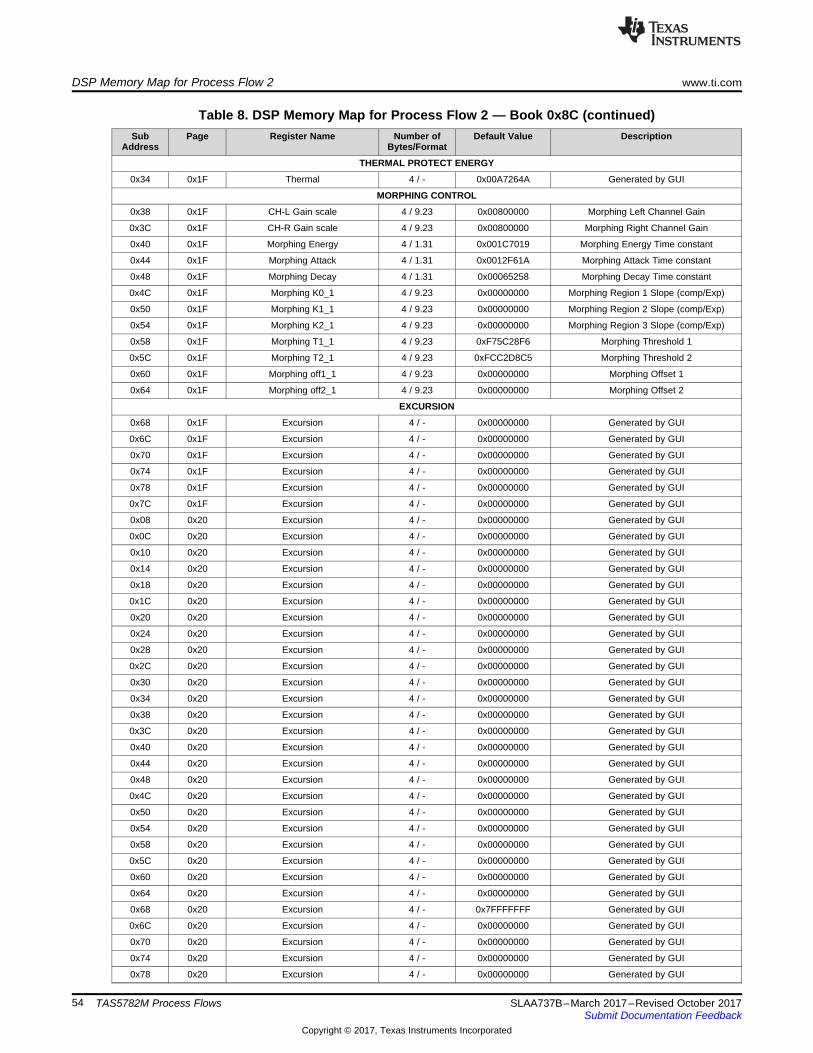
DSP Memory Map for Process Flow 2 www.ti.com
54 SLAA737B–March 2017–Revised October 2017Submit Documentation Feedback
Copyright © 2017, Texas Instruments Incorporated
TAS5782M Process Flows
Table 8. DSP Memory Map for Process Flow 2 — Book 0x8C (continued)Sub
AddressPage Register Name Number of
Bytes/FormatDefault Value Description
THERMAL PROTECT ENERGY
0x34 0x1F Thermal 4 / - 0x00A7264A Generated by GUI
MORPHING CONTROL
0x38 0x1F CH-L Gain scale 4 / 9.23 0x00800000 Morphing Left Channel Gain
0x3C 0x1F CH-R Gain scale 4 / 9.23 0x00800000 Morphing Right Channel Gain
0x40 0x1F Morphing Energy 4 / 1.31 0x001C7019 Morphing Energy Time constant
0x44 0x1F Morphing Attack 4 / 1.31 0x0012F61A Morphing Attack Time constant
0x48 0x1F Morphing Decay 4 / 1.31 0x00065258 Morphing Decay Time constant
0x4C 0x1F Morphing K0_1 4 / 9.23 0x00000000 Morphing Region 1 Slope (comp/Exp)
0x50 0x1F Morphing K1_1 4 / 9.23 0x00000000 Morphing Region 2 Slope (comp/Exp)
0x54 0x1F Morphing K2_1 4 / 9.23 0x00000000 Morphing Region 3 Slope (comp/Exp)
0x58 0x1F Morphing T1_1 4 / 9.23 0xF75C28F6 Morphing Threshold 1
0x5C 0x1F Morphing T2_1 4 / 9.23 0xFCC2D8C5 Morphing Threshold 2
0x60 0x1F Morphing off1_1 4 / 9.23 0x00000000 Morphing Offset 1
0x64 0x1F Morphing off2_1 4 / 9.23 0x00000000 Morphing Offset 2
EXCURSION
0x68 0x1F Excursion 4 / - 0x00000000 Generated by GUI
0x6C 0x1F Excursion 4 / - 0x00000000 Generated by GUI
0x70 0x1F Excursion 4 / - 0x00000000 Generated by GUI
0x74 0x1F Excursion 4 / - 0x00000000 Generated by GUI
0x78 0x1F Excursion 4 / - 0x00000000 Generated by GUI
0x7C 0x1F Excursion 4 / - 0x00000000 Generated by GUI
0x08 0x20 Excursion 4 / - 0x00000000 Generated by GUI
0x0C 0x20 Excursion 4 / - 0x00000000 Generated by GUI
0x10 0x20 Excursion 4 / - 0x00000000 Generated by GUI
0x14 0x20 Excursion 4 / - 0x00000000 Generated by GUI
0x18 0x20 Excursion 4 / - 0x00000000 Generated by GUI
0x1C 0x20 Excursion 4 / - 0x00000000 Generated by GUI
0x20 0x20 Excursion 4 / - 0x00000000 Generated by GUI
0x24 0x20 Excursion 4 / - 0x00000000 Generated by GUI
0x28 0x20 Excursion 4 / - 0x00000000 Generated by GUI
0x2C 0x20 Excursion 4 / - 0x00000000 Generated by GUI
0x30 0x20 Excursion 4 / - 0x00000000 Generated by GUI
0x34 0x20 Excursion 4 / - 0x00000000 Generated by GUI
0x38 0x20 Excursion 4 / - 0x00000000 Generated by GUI
0x3C 0x20 Excursion 4 / - 0x00000000 Generated by GUI
0x40 0x20 Excursion 4 / - 0x00000000 Generated by GUI
0x44 0x20 Excursion 4 / - 0x00000000 Generated by GUI
0x48 0x20 Excursion 4 / - 0x00000000 Generated by GUI
0x4C 0x20 Excursion 4 / - 0x00000000 Generated by GUI
0x50 0x20 Excursion 4 / - 0x00000000 Generated by GUI
0x54 0x20 Excursion 4 / - 0x00000000 Generated by GUI
0x58 0x20 Excursion 4 / - 0x00000000 Generated by GUI
0x5C 0x20 Excursion 4 / - 0x00000000 Generated by GUI
0x60 0x20 Excursion 4 / - 0x00000000 Generated by GUI
0x64 0x20 Excursion 4 / - 0x00000000 Generated by GUI
0x68 0x20 Excursion 4 / - 0x7FFFFFFF Generated by GUI
0x6C 0x20 Excursion 4 / - 0x00000000 Generated by GUI
0x70 0x20 Excursion 4 / - 0x00000000 Generated by GUI
0x74 0x20 Excursion 4 / - 0x00000000 Generated by GUI
0x78 0x20 Excursion 4 / - 0x00000000 Generated by GUI

www.ti.com DSP Memory Map for Process Flow 2
55SLAA737B–March 2017–Revised October 2017Submit Documentation Feedback
Copyright © 2017, Texas Instruments Incorporated
TAS5782M Process Flows
Table 8. DSP Memory Map for Process Flow 2 — Book 0x8C (continued)Sub
AddressPage Register Name Number of
Bytes/FormatDefault Value Description
0x7C 0x20 Excursion 4 / - 0x7FFFFFFF Generated by GUI
0x08 0x21 Excursion 4 / - 0x00000000 Generated by GUI
0x0C 0x21 Excursion 4 / - 0x00000000 Generated by GUI
0x10 0x21 Excursion 4 / - 0x00000000 Generated by GUI
0x14 0x21 Excursion 4 / - 0x00000000 Generated by GUI
0x18 0x21 Excursion 4 / - 0x7FFFFFFF Generated by GUI
0x1C 0x21 Excursion 4 / - 0xFF18B74D Generated by GUI
0x20 0x21 Excursion 4 / - 0x00800000 Generated by GUI
MORPHING BQs
0x24 0x21 CH-L BQ 1 B0 4 / 1.31 0x7FFFFFFF Left Channel Morphing BQ coefficient
0x28 0x21 CH-L BQ 1 B1 4 / 2.30 0x00000000 Left Channel Morphing BQ coefficient
0x2C 0x21 CH-L BQ 1 B2 4 / 1.31 0x00000000 Left Channel Morphing BQ coefficient
0x30 0x21 CH-L BQ 1 A1 4 / 2.30 0x00000000 Left Channel Morphing BQ coefficient
0x34 0x21 CH-L BQ 1 A2 4 / 1.31 0x00000000 Left Channel Morphing BQ coefficient
0x38 0x21 CH-L BQ 2 B0 4 / 1.31 0x7FFFFFFF Left Channel Morphing BQ coefficient
0x3C 0x21 CH-L BQ 2 B1 4 / 2.30 0x00000000 Left Channel Morphing BQ coefficient
0x40 0x21 CH-L BQ 2 B2 4 / 1.31 0x00000000 Left Channel Morphing BQ coefficient
0x44 0x21 CH-L BQ 2 A1 4 / 2.30 0x00000000 Left Channel Morphing BQ coefficient
0x48 0x21 CH-L BQ 2 A2 4 / 1.31 0x00000000 Left Channel Morphing BQ coefficient
0x4C 0x21 CH-R BQ 1 B0 4 / 1.31 0x7FFFFFFF Right Channel Morphing BQ coefficient
0x50 0x21 CH-R BQ 1 B1 4 / 2.30 0x00000000 Right Channel Morphing BQ coefficient
0x54 0x21 CH-R BQ 1 B2 4 / 1.31 0x00000000 Right Channel Morphing BQ coefficient
0x58 0x21 CH-R BQ 1 A1 4 / 2.30 0x00000000 Right Channel Morphing BQ coefficient
0x5C 0x21 CH-R BQ 1 A2 4 / 1.31 0x00000000 Right Channel Morphing BQ coefficient
0x60 0x21 CH-R BQ 2 B0 4 / 1.31 0x7FFFFFFF Right Channel Morphing BQ coefficient
0x64 0x21 CH-R BQ 2 B1 4 / 2.30 0x00000000 Right Channel Morphing BQ coefficient
0x68 0x21 CH-R BQ 2 B2 4 / 1.31 0x00000000 Right Channel Morphing BQ coefficient
0x6C 0x21 CH-R BQ 2 A1 4 / 2.30 0x00000000 Right Channel Morphing BQ coefficient
0x70 0x21 CH-R BQ 2 A2 4 / 1.31 0x00000000 Right Channel Morphing BQ coefficient
THERMAL PROTECT THRESHOLD
0x74 0x21 Thermal 4 / - 0x7FFFFFFF Generated by GUI

DSP Memory Map for Process Flow 3 www.ti.com
56 SLAA737B–March 2017–Revised October 2017Submit Documentation Feedback
Copyright © 2017, Texas Instruments Incorporated
TAS5782M Process Flows
A.3 DSP Memory Map for Process Flow 3Table 9 lists the DSP memory map for process flow 3.
Table 9. DSP Memory Map for Process Flow 3 — Book 0x8CSub
AddressPage Register Name Number of
Bytes/FormatDefault Value Description
BASS MONO MIXER
0x58 0x11 BQ 1 B0 4 / 1.31 0x7FFFFFFF Main Channel BQ coefficient
0x5C 0x11 BQ 1 B1 4 / 2.30 0x00000000 Main Channel BQ coefficient
0x60 0x11 BQ 1 B2 4 / 1.31 0x00000000 Main Channel BQ coefficient
0x64 0x11 BQ 1 A1 4 / 2.30 0x00000000 Main Channel BQ coefficient
0x68 0x11 BQ 1 A2 4 / 1.31 0x00000000 Main Channel BQ coefficient
0x44 0x12 CH-Sub BQ 1 B0 4 / 1.31 0x7FFFFFFF Sub Channel BQ coefficient
0x48 0x12 CH-Sub BQ 1 B1 4 / 2.30 0x00000000 Sub Channel BQ coefficient
0x4C 0x12 CH-Sub BQ 1 B2 4 / 1.31 0x00000000 Sub Channel BQ coefficient
0x50 0x12 CH-Sub BQ 1 A1 4 / 2.30 0x00000000 Sub Channel BQ coefficient
0x54 0x12 CH-Sub BQ 1 A2 4 / 1.31 0x00000000 Sub Channel BQ coefficient
DRC 1 BQ
0x30 0x13 BQ B0 4 / 1.31 0x7FFFFFFF DRC 1 BQ coefficient
0x34 0x13 BQ B1 4 / 2.30 0x00000000 DRC 1 BQ coefficient
0x38 0x13 BQ B2 4 / 1.31 0x00000000 DRC 1 BQ coefficient
0x3C 0x13 BQ A1 4 / 2.30 0x00000000 DRC 1 BQ coefficient
0x40 0x13 BQ A2 4 / 1.31 0x00000000 DRC 1 BQ coefficient
DRC 3 BQ
0x58 0x13 BQ B0 4 / 1.31 0x7FFFFFFF DRC 3 BQ coefficient
0x5C 0x13 BQ B1 4 / 2.30 0x00000000 DRC 3 BQ coefficient
0x60 0x13 BQ B2 4 / 1.31 0x00000000 DRC 3 BQ coefficient
0x64 0x13 BQ A1 4 / 2.30 0x00000000 DRC 3 BQ coefficient
0x68 0x13 BQ A2 4 / 1.31 0x00000000 DRC 3 BQ coefficient
DRC 2 BQ
0x08 0x14 BQ 1 B0 4 / 1.31 0x7FFFFFFF DRC 2 BQ coefficient
0x0C 0x14 BQ 1 B1 4 / 2.30 0x00000000 DRC 2 BQ coefficient
0x10 0x14 BQ 1 B2 4 / 1.31 0x00000000 DRC 2 BQ coefficient
0x14 0x14 BQ 1 A1 4 / 2.30 0x00000000 DRC 2 BQ coefficient
0x18 0x14 BQ 1 A2 4 / 1.31 0x00000000 DRC 2 BQ coefficient
0x1C 0x14 BQ 2 B0 4 / 1.31 0x7FFFFFFF DRC 2 BQ coefficient
0x20 0x14 BQ 2 B1 4 / 2.30 0x00000000 DRC 2 BQ coefficient
0x24 0x14 BQ 2 B2 4 / 1.31 0x00000000 DRC 2 BQ coefficient
0x28 0x14 BQ 2 A1 4 / 2.30 0x00000000 DRC 2 BQ coefficient
0x2C 0x14 BQ 2 A2 4 / 1.31 0x00000000 DRC 2 BQ coefficient
DPEQ SENSE BQ
0x58 0x14 BQ 1 B0 4 / 1.31 0x7FFFFFFF DPEQ sense BQ coefficient
0x5C 0x14 BQ 1 B1 4 / 2.30 0x00000000 DPEQ sense BQ coefficient
0x60 0x14 BQ 1 B2 4 / 1.31 0x00000000 DPEQ sense BQ coefficient
0x64 0x14 BQ 1 A1 4 / 2.30 0x00000000 DPEQ sense BQ coefficient
0x68 0x14 BQ 1 A2 4 / 1.31 0x00000000 DPEQ sense BQ coefficient
0x6C 0x14 BQ 2 B0 4 / 1.31 0x7FFFFFFF DPEQ sense BQ coefficient
0x70 0x14 BQ 2 B1 4 / 2.30 0x00000000 DPEQ sense BQ coefficient
0x74 0x14 BQ 2 B2 4 / 1.31 0x00000000 DPEQ sense BQ coefficient
0x78 0x14 BQ 2 A1 4 / 2.30 0x00000000 DPEQ sense BQ coefficient
0x7C 0x14 BQ 2 A2 4 / 1.31 0x00000000 DPEQ sense BQ coefficient
DPEQ LOW LEVEL PATH BQ
0x08 0x15 BQ 1 B0 4 / 1.31 0x7FFFFFFF DPEQ low BQ coefficient
0x0C 0x15 BQ 1 B1 4 / 2.30 0x00000000 DPEQ low BQ coefficient

www.ti.com DSP Memory Map for Process Flow 3
57SLAA737B–March 2017–Revised October 2017Submit Documentation Feedback
Copyright © 2017, Texas Instruments Incorporated
TAS5782M Process Flows
Table 9. DSP Memory Map for Process Flow 3 — Book 0x8C (continued)Sub
AddressPage Register Name Number of
Bytes/FormatDefault Value Description
0x10 0x15 BQ 1 B2 4 / 1.31 0x00000000 DPEQ low BQ coefficient
0x14 0x15 BQ 1 A1 4 / 2.30 0x00000000 DPEQ low BQ coefficient
0x18 0x15 BQ 1 A2 4 / 1.31 0x00000000 DPEQ low BQ coefficient
0x1C 0x15 BQ 2 B0 4 / 1.31 0x7FFFFFFF DPEQ low BQ coefficient
0x20 0x15 BQ 2 B1 4 / 2.30 0x00000000 DPEQ low BQ coefficient
0x24 0x15 BQ 2 B2 4 / 1.31 0x00000000 DPEQ low BQ coefficient
0x28 0x15 BQ 2 A1 4 / 2.30 0x00000000 DPEQ low BQ coefficient
0x2C 0x15 BQ 2 A2 4 / 1.31 0x00000000 DPEQ low BQ coefficient
DPEQ HIGH LEVEL PATH BQ
0x30 0x15 BQ 1 B0 4 / 1.31 0x7FFFFFFF DPEQ high BQ coefficient
0x34 0x15 BQ 1 B1 4 / 2.30 0x00000000 DPEQ high BQ coefficient
0x38 0x15 BQ 1 B2 4 / 1.31 0x00000000 DPEQ high BQ coefficient
0x3C 0x15 BQ 1 A1 4 / 2.30 0x00000000 DPEQ high BQ coefficient
0x40 0x15 BQ 1 A2 4 / 1.31 0x00000000 DPEQ high BQ coefficient
0x44 0x15 BQ 2 B0 4 / 1.31 0x7FFFFFFF DPEQ high BQ coefficient
0x48 0x15 BQ 2 B1 4 / 2.30 0x00000000 DPEQ high BQ coefficient
0x4C 0x15 BQ 2 B2 4 / 1.31 0x00000000 DPEQ high BQ coefficient
0x50 0x15 BQ 2 A1 4 / 2.30 0x00000000 DPEQ high BQ coefficient
0x54 0x15 BQ 2 A2 4 / 1.31 0x00000000 DPEQ high BQ coefficient
EQ LEFT 14 BQs
0x58 0x15 CH -L BQ 1 B0 4 / 1.31 0x7FFFFFFF Left BQ coefficient
0x5C 0x15 CH -L BQ 1 B1 4 / 2.30 0x00000000 Left BQ coefficient
0x60 0x15 CH -L BQ 1 B2 4 / 1.31 0x00000000 Left BQ coefficient
0x64 0x15 CH -L BQ 1 A1 4 / 2.30 0x00000000 Left BQ coefficient
0x68 0x15 CH -L BQ 1 A2 4 / 1.31 0x00000000 Left BQ coefficient
0x6C 0x15 CH -L BQ 2 B0 4 / 1.31 0x7FFFFFFF Left BQ coefficient
0x70 0x15 CH -L BQ 2 B1 4 / 2.30 0x00000000 Left BQ coefficient
0x74 0x15 CH -L BQ 2 B2 4 / 1.31 0x00000000 Left BQ coefficient
0x78 0x15 CH -L BQ 2 A1 4 / 2.30 0x00000000 Left BQ coefficient
0x7C 0x15 CH -L BQ 2 A2 4 / 1.31 0x00000000 Left BQ coefficient
0x08 0x16 CH -L BQ 3 B0 4 / 1.31 0x7FFFFFFF Left BQ coefficient
0x0C 0x16 CH -L BQ 3 B1 4 / 2.30 0x00000000 Left BQ coefficient
0x10 0x16 CH -L BQ 3 B2 4 / 1.31 0x00000000 Left BQ coefficient
0x14 0x16 CH -L BQ 3 A1 4 / 2.30 0x00000000 Left BQ coefficient
0x18 0x16 CH -L BQ 3 A2 4 / 1.31 0x00000000 Left BQ coefficient
0x1C 0x16 CH -L BQ 4 B0 4 / 1.31 0x7FFFFFFF Left BQ coefficient
0x20 0x16 CH -L BQ 4 B1 4 / 2.30 0x00000000 Left BQ coefficient
0x24 0x16 CH -L BQ 4 B2 4 / 1.31 0x00000000 Left BQ coefficient
0x28 0x16 CH -L BQ 4 A1 4 / 2.30 0x00000000 Left BQ coefficient
0x2C 0x16 CH -L BQ 4 A2 4 / 1.31 0x00000000 Left BQ coefficient
0x30 0x16 CH -L BQ 5 B0 4 / 1.31 0x7FFFFFFF Left BQ coefficient
0x34 0x16 CH -L BQ 5 B1 4 / 2.30 0x00000000 Left BQ coefficient
0x38 0x16 CH -L BQ 5 B2 4 / 1.31 0x00000000 Left BQ coefficient
0x3C 0x16 CH -L BQ 5 A1 4 / 2.30 0x00000000 Left BQ coefficient
0x40 0x16 CH -L BQ 5 A2 4 / 1.31 0x00000000 Left BQ coefficient
0x44 0x16 CH -L BQ 6 B0 4 / 1.31 0x7FFFFFFF Left BQ coefficient
0x48 0x16 CH -L BQ 6 B1 4 / 2.30 0x00000000 Left BQ coefficient
0x4C 0x16 CH -L BQ 6 B2 4 / 1.31 0x00000000 Left BQ coefficient
0x50 0x16 CH -L BQ 6 A1 4 / 2.30 0x00000000 Left BQ coefficient
0x54 0x16 CH -LBQ 6 A2 4 / 1.31 0x00000000 Left BQ coefficient
0x58 0x16 CH -L BQ 7 B0 4 / 1.31 0x7FFFFFFF Left BQ coefficient

DSP Memory Map for Process Flow 3 www.ti.com
58 SLAA737B–March 2017–Revised October 2017Submit Documentation Feedback
Copyright © 2017, Texas Instruments Incorporated
TAS5782M Process Flows
Table 9. DSP Memory Map for Process Flow 3 — Book 0x8C (continued)Sub
AddressPage Register Name Number of
Bytes/FormatDefault Value Description
0x5C 0x16 CH -L BQ 7 B1 4 / 2.30 0x00000000 Left BQ coefficient
0x60 0x16 CH -L BQ 7 B2 4 / 1.31 0x00000000 Left BQ coefficient
0x64 0x16 CH -L BQ 7 A1 4 / 2.30 0x00000000 Left BQ coefficient
0x68 0x16 CH -L BQ 7 A2 4 / 1.31 0x00000000 Left BQ coefficient
0x6C 0x16 CH -L BQ 8 B0 4 / 1.31 0x7FFFFFFF Left BQ coefficient
0x70 0x16 CH -L BQ 8 B1 4 / 2.30 0x00000000 Left BQ coefficient
0x74 0x16 CH -L BQ 8 B2 4 / 1.31 0x00000000 Left BQ coefficient
0x78 0x16 CH -L BQ 8 A1 4 / 2.30 0x00000000 Left BQ coefficient
0x7C 0x16 CH -L BQ 8 A2 4 / 1.31 0x00000000 Left BQ coefficient
0x08 0x17 CH -L BQ 9 B0 4 / 1.31 0x7FFFFFFF Left BQ coefficient
0x0C 0x17 CH -L BQ 9 B1 4 / 2.30 0x00000000 Left BQ coefficient
0x10 0x17 CH -L BQ 9 B2 4 / 1.31 0x00000000 Left BQ coefficient
0x14 0x17 CH -L BQ 9 A1 4 / 2.30 0x00000000 Left BQ coefficient
0x18 0x17 CH -L BQ 9 A2 4 / 1.31 0x00000000 Left BQ coefficient
0x1C 0x17 CH -L BQ 10 B0 4 / 1.31 0x7FFFFFFF Left BQ coefficient
0x20 0x17 CH -L BQ 10 B1 4 / 2.30 0x00000000 Left BQ coefficient
0x24 0x17 CH -L BQ 10 B2 4 / 1.31 0x00000000 Left BQ coefficient
0x28 0x17 CH -L BQ 10 A1 4 / 2.30 0x00000000 Left BQ coefficient
0x2C 0x17 CH -L BQ 10 A2 4 / 1.31 0x00000000 Left BQ coefficient
0x30 0x17 CH -L BQ 11 B0 4 / 1.31 0x7FFFFFFF Left BQ coefficient
0x34 0x17 CH -L BQ 11 B1 4 / 2.30 0x00000000 Left BQ coefficient
0x38 0x17 CH -L BQ 11 B2 4 / 1.31 0x00000000 Left BQ coefficient
0x3C 0x17 CH -L BQ 11 A1 4 / 2.30 0x00000000 Left BQ coefficient
0x40 0x17 CH -L BQ 11 A2 4 / 1.31 0x00000000 Left BQ coefficient
0x44 0x17 CH -L BQ 12 B0 4 / 1.31 0x7FFFFFFF Left BQ coefficient
0x48 0x17 CH -L BQ 12 B1 4 / 2.30 0x00000000 Left BQ coefficient
0x4C 0x17 CH -L BQ 12 B2 4 / 1.31 0x00000000 Left BQ coefficient
0x50 0x17 CH -L BQ 12 A1 4 / 2.30 0x00000000 Left BQ coefficient
0x54 0x17 CH -L BQ 12 A2 4 / 1.31 0x00000000 Left BQ coefficient
0x58 0x17 CH -L BQ 13 B0 4 / 1.31 0x7FFFFFFF Left BQ coefficient
0x5C 0x17 CH -L BQ 13 B1 4 / 2.30 0x00000000 Left BQ coefficient
0x60 0x17 CH -L BQ 13 B2 4 / 1.31 0x00000000 Left BQ coefficient
0x64 0x17 CH -L BQ 13 A1 4 / 2.30 0x00000000 Left BQ coefficient
0x68 0x17 CH -L BQ 13 A2 4 / 1.31 0x00000000 Left BQ coefficient
0x6C 0x17 CH -L BQ 14 B0 4 / 1.31 0x7FFFFFFF Left BQ coefficient
0x70 0x17 CH -L BQ 14 B1 4 / 2.30 0x00000000 Left BQ coefficient
0x74 0x17 CH -L BQ 14 B2 4 / 1.31 0x00000000 Left BQ coefficient
0x78 0x17 CH -L BQ 14 A1 4 / 2.30 0x00000000 Left BQ coefficient
0x7C 0x17 CH -L BQ 14 A2 4 / 1.31 0x00000000 Left BQ coefficient
LEFT INTGAIN BQ
0x08 0x18 CH -L BQ 15 B0 4 / 5.27 0x08000000 Left gain scale BQ coefficient
0x0C 0x18 CH -L BQ 15 B1 4 / 6.26 0x00000000 Left gain scale BQ coefficient
0x10 0x18 CH -L BQ 15 B2 4 / 5.27 0x00000000 Left gain scale BQ coefficient
0x14 0x18 CH -L BQ 15 A1 4 / 2.30 0x00000000 Left gain scale BQ coefficient
0x18 0x18 CH -L BQ 15 A2 4 / 1.31 0x00000000 Left gain scale BQ coefficient
EQ RIGHT 14 BQs
0x1C 0x18 CH -R BQ 1 B0 4 / 1.31 0x7FFFFFFF Right BQ coefficient
0x20 0x18 CH -R BQ 1 B1 4 / 2.30 0x00000000 Right BQ coefficient
0x24 0x18 CH -R BQ 1 B2 4 / 1.31 0x00000000 Right BQ coefficient
0x28 0x18 CH -R BQ 1 A1 4 / 2.30 0x00000000 Right BQ coefficient
0x2C 0x18 CH -R BQ 1 A2 4 / 1.31 0x00000000 Right BQ coefficient

www.ti.com DSP Memory Map for Process Flow 3
59SLAA737B–March 2017–Revised October 2017Submit Documentation Feedback
Copyright © 2017, Texas Instruments Incorporated
TAS5782M Process Flows
Table 9. DSP Memory Map for Process Flow 3 — Book 0x8C (continued)Sub
AddressPage Register Name Number of
Bytes/FormatDefault Value Description
0x30 0x18 CH -R BQ 2 B0 4 / 1.31 0x7FFFFFFF Right BQ coefficient
0x34 0x18 CH -R BQ 2 B1 4 / 2.30 0x00000000 Right BQ coefficient
0x38 0x18 CH -R BQ 2 B2 4 / 1.31 0x00000000 Right BQ coefficient
0x3C 0x18 CH -R BQ 2 A1 4 / 2.30 0x00000000 Right BQ coefficient
0x40 0x18 CH -R BQ 2 A2 4 / 1.31 0x00000000 Right BQ coefficient
0x44 0x18 CH -R BQ 3 B0 4 / 1.31 0x7FFFFFFF Right BQ coefficient
0x48 0x18 CH -R BQ 3 B1 4 / 2.30 0x00000000 Right BQ coefficient
0x4C 0x18 CH -R BQ 3 B2 4 / 1.31 0x00000000 Right BQ coefficient
0x50 0x18 CH -R BQ 3 A1 4 / 2.30 0x00000000 Right BQ coefficient
0x54 0x18 CH -R BQ 3 A2 4 / 1.31 0x00000000 Right BQ coefficient
0x58 0x18 CH -R BQ 4 B0 4 / 1.31 0x7FFFFFFF Right BQ coefficient
0x5C 0x18 CH -R BQ 4 B1 4 / 2.30 0x00000000 Right BQ coefficient
0x60 0x18 CH -R BQ 4 B2 4 / 1.31 0x00000000 Right BQ coefficient
0x64 0x18 CH -R BQ 4 A1 4 / 2.30 0x00000000 Right BQ coefficient
0x68 0x18 CH -R BQ 4 A2 4 / 1.31 0x00000000 Right BQ coefficient
0x6C 0x18 CH -R BQ 5 B0 4 / 1.31 0x7FFFFFFF Right BQ coefficient
0x70 0x18 CH -R BQ 5 B1 4 / 2.30 0x00000000 Right BQ coefficient
0x74 0x18 CH -R BQ 5 B2 4 / 1.31 0x00000000 Right BQ coefficient
0x78 0x18 CH -R BQ 5 A1 4 / 2.30 0x00000000 Right BQ coefficient
0x7C 0x18 CH -R BQ 5 A2 4 / 1.31 0x00000000 Right BQ coefficient
0x08 0x19 CH -R BQ 6 B0 4 / 1.31 0x7FFFFFFF Right BQ coefficient
0x0C 0x19 CH -R BQ 6 B1 4 / 2.30 0x00000000 Right BQ coefficient
0x10 0x19 CH -R BQ 6 B2 4 / 1.31 0x00000000 Right BQ coefficient
0x14 0x19 CH -R BQ 6 A1 4 / 2.30 0x00000000 Right BQ coefficient
0x18 0x19 CH -R BQ 6 A2 4 / 1.31 0x00000000 Right BQ coefficient
0x1C 0x19 CH -R BQ 7 B0 4 / 1.31 0x7FFFFFFF Right BQ coefficient
0x20 0x19 CH -R BQ 7 B1 4 / 2.30 0x00000000 Right BQ coefficient
0x24 0x19 CH -R BQ 7 B2 4 / 1.31 0x00000000 Right BQ coefficient
0x28 0x19 CH -R BQ 7 A1 4 / 2.30 0x00000000 Right BQ coefficient
0x2C 0x19 CH -R BQ 7 A2 4 / 1.31 0x00000000 Right BQ coefficient
0x30 0x19 CH -R BQ 8 B0 4 / 1.31 0x7FFFFFFF Right BQ coefficient
0x34 0x19 CH -R BQ 8 B1 4 / 2.30 0x00000000 Right BQ coefficient
0x38 0x19 CH -R BQ 8 B2 4 / 1.31 0x00000000 Right BQ coefficient
0x3C 0x19 CH -R BQ 8 A1 4 / 2.30 0x00000000 Right BQ coefficient
0x40 0x19 CH -R BQ 8 A2 4 / 1.31 0x00000000 Right BQ coefficient
0x44 0x19 CH -R BQ 9 B0 4 / 1.31 0x7FFFFFFF Right BQ coefficient
0x48 0x19 CH -R BQ 9 B1 4 / 2.30 0x00000000 Right BQ coefficient
0x4C 0x19 CH -R BQ 9 B2 4 / 1.31 0x00000000 Right BQ coefficient
0x50 0x19 CH -R BQ 9 A1 4 / 2.30 0x00000000 Right BQ coefficient
0x54 0x19 CH -R BQ 9 A2 4 / 1.31 0x00000000 Right BQ coefficient
0x58 0x19 CH -R BQ 10 B0 4 / 1.31 0x7FFFFFFF Right BQ coefficient
0x5C 0x19 CH -R BQ 10 B1 4 / 2.30 0x00000000 Right BQ coefficient
0x60 0x19 CH -R BQ 10 B2 4 / 1.31 0x00000000 Right BQ coefficient
0x64 0x19 CH -R BQ 10 A1 4 / 2.30 0x00000000 Right BQ coefficient
0x68 0x19 CH -R BQ 10 A2 4 / 1.31 0x00000000 Right BQ coefficient
0x6C 0x19 CH -R BQ 11 B0 4 / 1.31 0x7FFFFFFF Right BQ coefficient
0x70 0x19 CH -R BQ 11 B1 4 / 2.30 0x00000000 Right BQ coefficient
0x74 0x19 CH -R BQ 11 B2 4 / 1.31 0x00000000 Right BQ coefficient
0x78 0x19 CH -R BQ 11 A1 4 / 2.30 0x00000000 Right BQ coefficient
0x7C 0x19 CH -R BQ 11 A2 4 / 1.31 0x00000000 Right BQ coefficient
0x08 0x1A CH -R BQ 12 B0 4 / 1.31 0x7FFFFFFF Right BQ coefficient
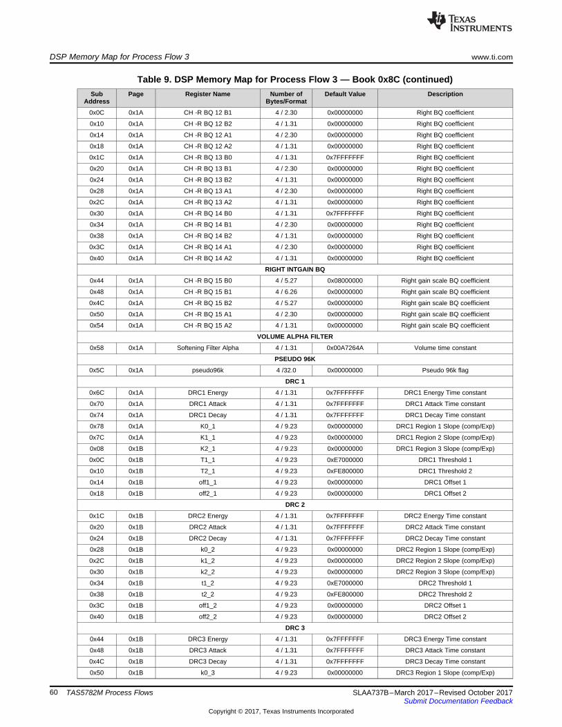
DSP Memory Map for Process Flow 3 www.ti.com
60 SLAA737B–March 2017–Revised October 2017Submit Documentation Feedback
Copyright © 2017, Texas Instruments Incorporated
TAS5782M Process Flows
Table 9. DSP Memory Map for Process Flow 3 — Book 0x8C (continued)Sub
AddressPage Register Name Number of
Bytes/FormatDefault Value Description
0x0C 0x1A CH -R BQ 12 B1 4 / 2.30 0x00000000 Right BQ coefficient
0x10 0x1A CH -R BQ 12 B2 4 / 1.31 0x00000000 Right BQ coefficient
0x14 0x1A CH -R BQ 12 A1 4 / 2.30 0x00000000 Right BQ coefficient
0x18 0x1A CH -R BQ 12 A2 4 / 1.31 0x00000000 Right BQ coefficient
0x1C 0x1A CH -R BQ 13 B0 4 / 1.31 0x7FFFFFFF Right BQ coefficient
0x20 0x1A CH -R BQ 13 B1 4 / 2.30 0x00000000 Right BQ coefficient
0x24 0x1A CH -R BQ 13 B2 4 / 1.31 0x00000000 Right BQ coefficient
0x28 0x1A CH -R BQ 13 A1 4 / 2.30 0x00000000 Right BQ coefficient
0x2C 0x1A CH -R BQ 13 A2 4 / 1.31 0x00000000 Right BQ coefficient
0x30 0x1A CH -R BQ 14 B0 4 / 1.31 0x7FFFFFFF Right BQ coefficient
0x34 0x1A CH -R BQ 14 B1 4 / 2.30 0x00000000 Right BQ coefficient
0x38 0x1A CH -R BQ 14 B2 4 / 1.31 0x00000000 Right BQ coefficient
0x3C 0x1A CH -R BQ 14 A1 4 / 2.30 0x00000000 Right BQ coefficient
0x40 0x1A CH -R BQ 14 A2 4 / 1.31 0x00000000 Right BQ coefficient
RIGHT INTGAIN BQ
0x44 0x1A CH -R BQ 15 B0 4 / 5.27 0x08000000 Right gain scale BQ coefficient
0x48 0x1A CH -R BQ 15 B1 4 / 6.26 0x00000000 Right gain scale BQ coefficient
0x4C 0x1A CH -R BQ 15 B2 4 / 5.27 0x00000000 Right gain scale BQ coefficient
0x50 0x1A CH -R BQ 15 A1 4 / 2.30 0x00000000 Right gain scale BQ coefficient
0x54 0x1A CH -R BQ 15 A2 4 / 1.31 0x00000000 Right gain scale BQ coefficient
VOLUME ALPHA FILTER
0x58 0x1A Softening Filter Alpha 4 / 1.31 0x00A7264A Volume time constant
PSEUDO 96K
0x5C 0x1A pseudo96k 4 /32.0 0x00000000 Pseudo 96k flag
DRC 1
0x6C 0x1A DRC1 Energy 4 / 1.31 0x7FFFFFFF DRC1 Energy Time constant
0x70 0x1A DRC1 Attack 4 / 1.31 0x7FFFFFFF DRC1 Attack Time constant
0x74 0x1A DRC1 Decay 4 / 1.31 0x7FFFFFFF DRC1 Decay Time constant
0x78 0x1A K0_1 4 / 9.23 0x00000000 DRC1 Region 1 Slope (comp/Exp)
0x7C 0x1A K1_1 4 / 9.23 0x00000000 DRC1 Region 2 Slope (comp/Exp)
0x08 0x1B K2_1 4 / 9.23 0x00000000 DRC1 Region 3 Slope (comp/Exp)
0x0C 0x1B T1_1 4 / 9.23 0xE7000000 DRC1 Threshold 1
0x10 0x1B T2_1 4 / 9.23 0xFE800000 DRC1 Threshold 2
0x14 0x1B off1_1 4 / 9.23 0x00000000 DRC1 Offset 1
0x18 0x1B off2_1 4 / 9.23 0x00000000 DRC1 Offset 2
DRC 2
0x1C 0x1B DRC2 Energy 4 / 1.31 0x7FFFFFFF DRC2 Energy Time constant
0x20 0x1B DRC2 Attack 4 / 1.31 0x7FFFFFFF DRC2 Attack Time constant
0x24 0x1B DRC2 Decay 4 / 1.31 0x7FFFFFFF DRC2 Decay Time constant
0x28 0x1B k0_2 4 / 9.23 0x00000000 DRC2 Region 1 Slope (comp/Exp)
0x2C 0x1B k1_2 4 / 9.23 0x00000000 DRC2 Region 2 Slope (comp/Exp)
0x30 0x1B k2_2 4 / 9.23 0x00000000 DRC2 Region 3 Slope (comp/Exp)
0x34 0x1B t1_2 4 / 9.23 0xE7000000 DRC2 Threshold 1
0x38 0x1B t2_2 4 / 9.23 0xFE800000 DRC2 Threshold 2
0x3C 0x1B off1_2 4 / 9.23 0x00000000 DRC2 Offset 1
0x40 0x1B off2_2 4 / 9.23 0x00000000 DRC2 Offset 2
DRC 3
0x44 0x1B DRC3 Energy 4 / 1.31 0x7FFFFFFF DRC3 Energy Time constant
0x48 0x1B DRC3 Attack 4 / 1.31 0x7FFFFFFF DRC3 Attack Time constant
0x4C 0x1B DRC3 Decay 4 / 1.31 0x7FFFFFFF DRC3 Decay Time constant
0x50 0x1B k0_3 4 / 9.23 0x00000000 DRC3 Region 1 Slope (comp/Exp)

www.ti.com DSP Memory Map for Process Flow 3
61SLAA737B–March 2017–Revised October 2017Submit Documentation Feedback
Copyright © 2017, Texas Instruments Incorporated
TAS5782M Process Flows
Table 9. DSP Memory Map for Process Flow 3 — Book 0x8C (continued)Sub
AddressPage Register Name Number of
Bytes/FormatDefault Value Description
0x54 0x1B k1_3 4 / 9.23 0x00000000 DRC3 Region 2 Slope (comp/Exp)
0x58 0x1B k1_3 4 / 9.23 0x00000000 DRC3 Region 3 Slope (comp/Exp)
0x5C 0x1B t1_3 4 / 9.23 0xE7000000 DRC3 Threshold 1
0x60 0x1B t2_3 4 / 9.23 0xFE800000 DRC3 Threshold 2
0x64 0x1B off1_3 4 / 9.23 0x00000000 DRC3 Offset 1
0x68 0x1B off2_3 4 / 9.23 0x00000000 DRC3 Offset 2
SPATIALIZER BQs
0x6C 0x1C BQ 1 B0 4 / 1.31 0x7FFFFFFF Spatializer BQ coefficient
0x70 0x1C BQ 1 B1 4 / 2.30 0x00000000 Spatializer BQ coefficient
0x74 0x1C BQ 1 B2 4 / 1.31 0x00000000 Spatializer BQ coefficient
0x78 0x1C BQ 1 A1 4 / 2.30 0x00000000 Spatializer BQ coefficient
0x7C 0x1C BQ 1 A2 4 / 1.31 0x00000000 Spatializer BQ coefficient
0x08 0x1D BQ 2 B0 4 / 1.31 0x7FFFFFFF Spatializer BQ coefficient
0x0C 0x1D BQ 2 B1 4 / 2.30 0x00000000 Spatializer BQ coefficient
0x10 0x1D BQ 2 B2 4 / 1.31 0x00000000 Spatializer BQ coefficient
0x14 0x1D BQ 2 A1 4 / 2.30 0x00000000 Spatializer BQ coefficient
0x18 0x1D BQ 2 A2 4 / 1.31 0x00000000 Spatializer BQ coefficient
DPEQ CONTROL
0x1C 0x1D Alpha 4 / 1.31 0x02DEAD00 DPEQ Sense Energy Time constant
0x20 0x1D Gain 4 / 1.31 0x74013901 DPEQ Threshold Gain
0x24 0x1D Offset 4 / 1.31 0x0020C49B DPEQ Threshold Offset
SUB CHANNEL CONTROL
0x28 0x1D No Sub 4 / 32.0 0x00000001 Sub Channel Flag
THD CLIPPER
0x2C 0x1D CH-LR THD Boost 4 / 9.23 0x00800000 THD LR Channel pre-scale coefficient
0x34 0x1D CH-L Fine Volume 4 / 2.30 0x3FFFFFFF THD L Channel post-scale coefficient
0x38 0x1D CH-R Fine Volume 4 / 2.30 0x3FFFFFFF THD R Channel post-scale coefficient
DRC MIXER GAIN
0x40 0x1D DRC 1 Mixer Gain 4 / 9.23 0x00800000 DRC 1 Mixer Gain coefficient
0x44 0x1D DRC 2 Mixer Gain 4 / 9.23 0x00000000 DRC 2 Mixer Gain coefficient
0x48 0x1D DRC 3 Mixer Gain 4 / 9.23 0x00000000 DRC 3 Mixer Gain coefficient
GANG EQ
0x58 0x1D Gang LR EQ 4 / 32.0 0x00000000 Gang Left and Right EQ flag
INPUT MIXER
0x5C 0x1D Left to Left 4 / 9.23 0x00800000 Left Channel Mixer Left Input Gain
0x60 0x1D Right to Left 4 / 9.23 0x00000000 Left Channel Mixer Right Input Gain
0x64 0x1D Left to Right 4 / 9.23 0x00000000 Right Channel Mixer Left Input Gain
0x68 0x1D Right to Right 4 / 9.23 0x00800000 Right Channel Mixer Right Input Gain
SPATIALIZER LEVEL
0x10 0x1E Spatializer Level 4 / 9.23 0x00000000 Spatializer Level coefficient
OUTPUT CROSS BAR
0x14 0x1E Digital Left from Left 4 / 9.23 0x00800000 I2S Left output gain from left
0x18 0x1E Digital Left from Right 4 / 9.23 0x00000000 I2S Left output gain from Right
0x20 0x1E Digital Right from Left 4 / 9.23 0x00000000 I2S Right output gain from left
0x24 0x1E Digital Right from Right 4 / 9.23 0x00800000 I2S Right output gain from Right
0x2C 0x1E Analog Left from Left 4 / 9.23 0x00800000 Analog Left output gain from left
0x30 0x1E Analog Left from Right 4 / 9.23 0x00000000 Analog Left output gain from Right
0x38 0x1E Analog Right from Left 4 / 9.23 0x00000000 Analog Right output gain from left
0x3C 0x1E Analog Right from Right 4 / 9.23 0x00800000 Analog Right output gain from Right

DSP Memory Map for Process Flow 3 www.ti.com
62 SLAA737B–March 2017–Revised October 2017Submit Documentation Feedback
Copyright © 2017, Texas Instruments Incorporated
TAS5782M Process Flows
Table 9. DSP Memory Map for Process Flow 3 — Book 0x8C (continued)Sub
AddressPage Register Name Number of
Bytes/FormatDefault Value Description
VOLUME CONTROL
0x44 0x1E CH-L Volume 4 / 9.23 0x00800000 Left Channel volume coefficient
0x48 0x1E CH-R Volume 4 / 9.23 0x00800000 Right Channel volume coefficient
DPEQ GAIN SCALE
0x50 0x1E DPEQ Sense Scale 4 / 2.30 0x40000000 DPEQ Sense Input Gain
0x54 0x1E DPEQ Low Scale 4 / 6.26 0x04000000 DPEQ Low Input Gain
0x58 0x1E DPEQ High Scale 4 / 6.26 0x04000000 DPEQ High Input Gain
AGL
0x14 0x1F Attack Threshold 4 / 1.31 0x40000000 Threshold linear
0x18 0x1F Softening Filter Alpha 4 / 1.31 0x06153BD1 AGL Alpha Time constant
0x1C 0x1F Attack Rate 4 / 1.31 0x0001B4E8 AGL Attack Time constant
0x20 0x1F AGL Enable 4 / 1.31 0x40000000 AGL Enable flag
0x28 0x1F Softening Filter Omega 4 / 1.31 0x79EAC42F AGL Omega Time constant
0x2C 0x1F Release Rate 4 / 1.31 0x00002BB1 AGL Release Time constant

www.ti.com DSP Memory Map for Process Flow 4
63SLAA737B–March 2017–Revised October 2017Submit Documentation Feedback
Copyright © 2017, Texas Instruments Incorporated
TAS5782M Process Flows
A.4 DSP Memory Map for Process Flow 4Table 10 lists the DSP memory map for process flow 4.
Table 10. DSP Memory Map for Process Flow 4 — Book 0x8CSub
AddressPage Register Name Number of
Bytes/FormatDefault Value Description
BASS MONO MIXER
0x58 0x11 BQ 1 B0 4 / 1.31 0x7FFFFFFF Main Channel BQ coefficient
0x5C 0x11 BQ 1 B1 4 / 2.30 0x00000000 Main Channel BQ coefficient
0x60 0x11 BQ 1 B2 4 / 1.31 0x00000000 Main Channel BQ coefficient
0x64 0x11 BQ 1 A1 4 / 2.30 0x00000000 Main Channel BQ coefficient
0x68 0x11 BQ 1 A2 4 / 1.31 0x00000000 Main Channel BQ coefficient
0x44 0x12 CH-Sub BQ 1 B0 4 / 1.31 0x7FFFFFFF Sub Channel BQ coefficient
0x48 0x12 CH-Sub BQ 1 B1 4 / 2.30 0x00000000 Sub Channel BQ coefficient
0x4C 0x12 CH-Sub BQ 1 B2 4 / 1.31 0x00000000 Sub Channel BQ coefficient
0x50 0x12 CH-Sub BQ 1 A1 4 / 2.30 0x00000000 Sub Channel BQ coefficient
0x54 0x12 CH-Sub BQ 1 A2 4 / 1.31 0x00000000 Sub Channel BQ coefficient
DPEQ SENSE BQ
0x58 0x14 BQ 1 B0 4 / 1.31 0x7FFFFFFF DPEQ sense BQ coefficient
0x5C 0x14 BQ 1 B1 4 / 2.30 0x00000000 DPEQ sense BQ coefficient
0x60 0x14 BQ 1 B2 4 / 1.31 0x00000000 DPEQ sense BQ coefficient
0x64 0x14 BQ 1 A1 4 / 2.30 0x00000000 DPEQ sense BQ coefficient
0x68 0x14 BQ 1 A2 4 / 1.31 0x00000000 DPEQ sense BQ coefficient
0x6C 0x14 BQ 2 B0 4 / 1.31 0x7FFFFFFF DPEQ sense BQ coefficient
0x70 0x14 BQ 2 B1 4 / 2.30 0x00000000 DPEQ sense BQ coefficient
0x74 0x14 BQ 2 B2 4 / 1.31 0x00000000 DPEQ sense BQ coefficient
0x78 0x14 BQ 2 A1 4 / 2.30 0x00000000 DPEQ sense BQ coefficient
0x7C 0x14 BQ 2 A2 4 / 1.31 0x00000000 DPEQ sense BQ coefficient
DPEQ LOW LEVEL PATH BQ
0x08 0x15 BQ 1 B0 4 / 1.31 0x7FFFFFFF DPEQ low BQ coefficient
0x0C 0x15 BQ 1 B1 4 / 2.30 0x00000000 DPEQ low BQ coefficient
0x10 0x15 BQ 1 B2 4 / 1.31 0x00000000 DPEQ low BQ coefficient
0x14 0x15 BQ 1 A1 4 / 2.30 0x00000000 DPEQ low BQ coefficient
0x18 0x15 BQ 1 A2 4 / 1.31 0x00000000 DPEQ low BQ coefficient
0x1C 0x15 BQ 2 B0 4 / 1.31 0x7FFFFFFF DPEQ low BQ coefficient
0x20 0x15 BQ 2 B1 4 / 2.30 0x00000000 DPEQ low BQ coefficient
0x24 0x15 BQ 2 B2 4 / 1.31 0x00000000 DPEQ low BQ coefficient
0x28 0x15 BQ 2 A1 4 / 2.30 0x00000000 DPEQ low BQ coefficient
0x2C 0x15 BQ 2 A2 4 / 1.31 0x00000000 DPEQ low BQ coefficient
DPEQ HIGH LEVEL PATH BQ
0x30 0x15 BQ 1 B0 4 / 1.31 0x7FFFFFFF DPEQ high BQ coefficient
0x34 0x15 BQ 1 B1 4 / 2.30 0x00000000 DPEQ high BQ coefficient
0x38 0x15 BQ 1 B2 4 / 1.31 0x00000000 DPEQ high BQ coefficient
0x3C 0x15 BQ 1 A1 4 / 2.30 0x00000000 DPEQ high BQ coefficient
0x40 0x15 BQ 1 A2 4 / 1.31 0x00000000 DPEQ high BQ coefficient
0x44 0x15 BQ 2 B0 4 / 1.31 0x7FFFFFFF DPEQ high BQ coefficient
0x48 0x15 BQ 2 B1 4 / 2.30 0x00000000 DPEQ high BQ coefficient
0x4C 0x15 BQ 2 B2 4 / 1.31 0x00000000 DPEQ high BQ coefficient
0x50 0x15 BQ 2 A1 4 / 2.30 0x00000000 DPEQ high BQ coefficient
0x54 0x15 BQ 2 A2 4 / 1.31 0x00000000 DPEQ high BQ coefficient
EQ LEFT 14 BQs
0x58 0x15 CH -L BQ 1 B0 4 / 1.31 0x7FFFFFFF Left BQ coefficient
0x5C 0x15 CH -L BQ 1 B1 4 / 2.30 0x00000000 Left BQ coefficient
0x60 0x15 CH -L BQ 1 B2 4 / 1.31 0x00000000 Left BQ coefficient

DSP Memory Map for Process Flow 4 www.ti.com
64 SLAA737B–March 2017–Revised October 2017Submit Documentation Feedback
Copyright © 2017, Texas Instruments Incorporated
TAS5782M Process Flows
Table 10. DSP Memory Map for Process Flow 4 — Book 0x8C (continued)Sub
AddressPage Register Name Number of
Bytes/FormatDefault Value Description
0x64 0x15 CH -L BQ 1 A1 4 / 2.30 0x00000000 Left BQ coefficient
0x68 0x15 CH -L BQ 1 A2 4 / 1.31 0x00000000 Left BQ coefficient
0x6C 0x15 CH -L BQ 2 B0 4 / 1.31 0x7FFFFFFF Left BQ coefficient
0x70 0x15 CH -L BQ 2 B1 4 / 2.30 0x00000000 Left BQ coefficient
0x74 0x15 CH -L BQ 2 B2 4 / 1.31 0x00000000 Left BQ coefficient
0x78 0x15 CH -L BQ 2 A1 4 / 2.30 0x00000000 Left BQ coefficient
0x7C 0x15 CH -L BQ 2 A2 4 / 1.31 0x00000000 Left BQ coefficient
0x08 0x16 CH -L BQ 3 B0 4 / 1.31 0x7FFFFFFF Left BQ coefficient
0x0C 0x16 CH -L BQ 3 B1 4 / 2.30 0x00000000 Left BQ coefficient
0x10 0x16 CH -L BQ 3 B2 4 / 1.31 0x00000000 Left BQ coefficient
0x14 0x16 CH -L BQ 3 A1 4 / 2.30 0x00000000 Left BQ coefficient
0x18 0x16 CH -L BQ 3 A2 4 / 1.31 0x00000000 Left BQ coefficient
0x1C 0x16 CH -L BQ 4 B0 4 / 1.31 0x7FFFFFFF Left BQ coefficient
0x20 0x16 CH -L BQ 4 B1 4 / 2.30 0x00000000 Left BQ coefficient
0x24 0x16 CH -L BQ 4 B2 4 / 1.31 0x00000000 Left BQ coefficient
0x28 0x16 CH -L BQ 4 A1 4 / 2.30 0x00000000 Left BQ coefficient
0x2C 0x16 CH -L BQ 4 A2 4 / 1.31 0x00000000 Left BQ coefficient
0x30 0x16 CH -L BQ 5 B0 4 / 1.31 0x7FFFFFFF Left BQ coefficient
0x34 0x16 CH -L BQ 5 B1 4 / 2.30 0x00000000 Left BQ coefficient
0x38 0x16 CH -L BQ 5 B2 4 / 1.31 0x00000000 Left BQ coefficient
0x3C 0x16 CH -L BQ 5 A1 4 / 2.30 0x00000000 Left BQ coefficient
0x40 0x16 CH -L BQ 5 A2 4 / 1.31 0x00000000 Left BQ coefficient
0x44 0x16 CH -L BQ 6 B0 4 / 1.31 0x7FFFFFFF Left BQ coefficient
0x48 0x16 CH -L BQ 6 B1 4 / 2.30 0x00000000 Left BQ coefficient
0x4C 0x16 CH -L BQ 6 B2 4 / 1.31 0x00000000 Left BQ coefficient
0x50 0x16 CH -L BQ 6 A1 4 / 2.30 0x00000000 Left BQ coefficient
0x54 0x16 CH -LBQ 6 A2 4 / 1.31 0x00000000 Left BQ coefficient
0x58 0x16 CH -L BQ 7 B0 4 / 1.31 0x7FFFFFFF Left BQ coefficient
0x5C 0x16 CH -L BQ 7 B1 4 / 2.30 0x00000000 Left BQ coefficient
0x60 0x16 CH -L BQ 7 B2 4 / 1.31 0x00000000 Left BQ coefficient
0x64 0x16 CH -L BQ 7 A1 4 / 2.30 0x00000000 Left BQ coefficient
0x68 0x16 CH -L BQ 7 A2 4 / 1.31 0x00000000 Left BQ coefficient
0x6C 0x16 CH -L BQ 8 B0 4 / 1.31 0x7FFFFFFF Left BQ coefficient
0x70 0x16 CH -L BQ 8 B1 4 / 2.30 0x00000000 Left BQ coefficient
0x74 0x16 CH -L BQ 8 B2 4 / 1.31 0x00000000 Left BQ coefficient
0x78 0x16 CH -L BQ 8 A1 4 / 2.30 0x00000000 Left BQ coefficient
0x7C 0x16 CH -L BQ 8 A2 4 / 1.31 0x00000000 Left BQ coefficient
0x08 0x17 CH -L BQ 9 B0 4 / 1.31 0x7FFFFFFF Left BQ coefficient
0x0C 0x17 CH -L BQ 9 B1 4 / 2.30 0x00000000 Left BQ coefficient
0x10 0x17 CH -L BQ 9 B2 4 / 1.31 0x00000000 Left BQ coefficient
0x14 0x17 CH -L BQ 9 A1 4 / 2.30 0x00000000 Left BQ coefficient
0x18 0x17 CH -L BQ 9 A2 4 / 1.31 0x00000000 Left BQ coefficient
0x1C 0x17 CH -L BQ 10 B0 4 / 1.31 0x7FFFFFFF Left BQ coefficient
0x20 0x17 CH -L BQ 10 B1 4 / 2.30 0x00000000 Left BQ coefficient
0x24 0x17 CH -L BQ 10 B2 4 / 1.31 0x00000000 Left BQ coefficient
0x28 0x17 CH -L BQ 10 A1 4 / 2.30 0x00000000 Left BQ coefficient
0x2C 0x17 CH -L BQ 10 A2 4 / 1.31 0x00000000 Left BQ coefficient
0x30 0x17 CH -L BQ 11 B0 4 / 1.31 0x7FFFFFFF Left BQ coefficient
0x34 0x17 CH -L BQ 11 B1 4 / 2.30 0x00000000 Left BQ coefficient
0x38 0x17 CH -L BQ 11 B2 4 / 1.31 0x00000000 Left BQ coefficient
0x3C 0x17 CH -L BQ 11 A1 4 / 2.30 0x00000000 Left BQ coefficient

www.ti.com DSP Memory Map for Process Flow 4
65SLAA737B–March 2017–Revised October 2017Submit Documentation Feedback
Copyright © 2017, Texas Instruments Incorporated
TAS5782M Process Flows
Table 10. DSP Memory Map for Process Flow 4 — Book 0x8C (continued)Sub
AddressPage Register Name Number of
Bytes/FormatDefault Value Description
0x40 0x17 CH -L BQ 11 A2 4 / 1.31 0x00000000 Left BQ coefficient
0x44 0x17 CH -L BQ 12 B0 4 / 1.31 0x7FFFFFFF Left BQ coefficient
0x48 0x17 CH -L BQ 12 B1 4 / 2.30 0x00000000 Left BQ coefficient
0x4C 0x17 CH -L BQ 12 B2 4 / 1.31 0x00000000 Left BQ coefficient
0x50 0x17 CH -L BQ 12 A1 4 / 2.30 0x00000000 Left BQ coefficient
0x54 0x17 CH -L BQ 12 A2 4 / 1.31 0x00000000 Left BQ coefficient
0x58 0x17 CH -L BQ 13 B0 4 / 1.31 0x7FFFFFFF Left BQ coefficient
0x5C 0x17 CH -L BQ 13 B1 4 / 2.30 0x00000000 Left BQ coefficient
0x60 0x17 CH -L BQ 13 B2 4 / 1.31 0x00000000 Left BQ coefficient
0x64 0x17 CH -L BQ 13 A1 4 / 2.30 0x00000000 Left BQ coefficient
0x68 0x17 CH -L BQ 13 A2 4 / 1.31 0x00000000 Left BQ coefficient
0x6C 0x17 CH -L BQ 14 B0 4 / 1.31 0x7FFFFFFF Left BQ coefficient
0x70 0x17 CH -L BQ 14 B1 4 / 2.30 0x00000000 Left BQ coefficient
0x74 0x17 CH -L BQ 14 B2 4 / 1.31 0x00000000 Left BQ coefficient
0x78 0x17 CH -L BQ 14 A1 4 / 2.30 0x00000000 Left BQ coefficient
0x7C 0x17 CH -L BQ 14 A2 4 / 1.31 0x00000000 Left BQ coefficient
LEFT INTGAIN BQ
0x08 0x18 CH -L BQ 15 B0 4 / 5.27 0x08000000 Left gain scale BQ coefficient
0x0C 0x18 CH -L BQ 15 B1 4 / 6.26 0x00000000 Left gain scale BQ coefficient
0x10 0x18 CH -L BQ 15 B2 4 / 5.27 0x00000000 Left gain scale BQ coefficient
0x14 0x18 CH -L BQ 15 A1 4 / 2.30 0x00000000 Left gain scale BQ coefficient
0x18 0x18 CH -L BQ 15 A2 4 / 1.31 0x00000000 Left gain scale BQ coefficient
EQ RIGHT 14 BQs
0x1C 0x18 CH -R BQ 1 B0 4 / 1.31 0x7FFFFFFF Right BQ coefficient
0x20 0x18 CH -R BQ 1 B1 4 / 2.30 0x00000000 Right BQ coefficient
0x24 0x18 CH -R BQ 1 B2 4 / 1.31 0x00000000 Right BQ coefficient
0x28 0x18 CH -R BQ 1 A1 4 / 2.30 0x00000000 Right BQ coefficient
0x2C 0x18 CH -R BQ 1 A2 4 / 1.31 0x00000000 Right BQ coefficient
0x30 0x18 CH -R BQ 2 B0 4 / 1.31 0x7FFFFFFF Right BQ coefficient
0x34 0x18 CH -R BQ 2 B1 4 / 2.30 0x00000000 Right BQ coefficient
0x38 0x18 CH -R BQ 2 B2 4 / 1.31 0x00000000 Right BQ coefficient
0x3C 0x18 CH -R BQ 2 A1 4 / 2.30 0x00000000 Right BQ coefficient
0x40 0x18 CH -R BQ 2 A2 4 / 1.31 0x00000000 Right BQ coefficient
0x44 0x18 CH -R BQ 3 B0 4 / 1.31 0x7FFFFFFF Right BQ coefficient
0x48 0x18 CH -R BQ 3 B1 4 / 2.30 0x00000000 Right BQ coefficient
0x4C 0x18 CH -R BQ 3 B2 4 / 1.31 0x00000000 Right BQ coefficient
0x50 0x18 CH -R BQ 3 A1 4 / 2.30 0x00000000 Right BQ coefficient
0x54 0x18 CH -R BQ 3 A2 4 / 1.31 0x00000000 Right BQ coefficient
0x58 0x18 CH -R BQ 4 B0 4 / 1.31 0x7FFFFFFF Right BQ coefficient
0x5C 0x18 CH -R BQ 4 B1 4 / 2.30 0x00000000 Right BQ coefficient
0x60 0x18 CH -R BQ 4 B2 4 / 1.31 0x00000000 Right BQ coefficient
0x64 0x18 CH -R BQ 4 A1 4 / 2.30 0x00000000 Right BQ coefficient
0x68 0x18 CH -R BQ 4 A2 4 / 1.31 0x00000000 Right BQ coefficient
0x6C 0x18 CH -R BQ 5 B0 4 / 1.31 0x7FFFFFFF Right BQ coefficient
0x70 0x18 CH -R BQ 5 B1 4 / 2.30 0x00000000 Right BQ coefficient
0x74 0x18 CH -R BQ 5 B2 4 / 1.31 0x00000000 Right BQ coefficient
0x78 0x18 CH -R BQ 5 A1 4 / 2.30 0x00000000 Right BQ coefficient
0x7C 0x18 CH -R BQ 5 A2 4 / 1.31 0x00000000 Right BQ coefficient
0x08 0x19 CH -R BQ 6 B0 4 / 1.31 0x7FFFFFFF Right BQ coefficient
0x0C 0x19 CH -R BQ 6 B1 4 / 2.30 0x00000000 Right BQ coefficient
0x10 0x19 CH -R BQ 6 B2 4 / 1.31 0x00000000 Right BQ coefficient

DSP Memory Map for Process Flow 4 www.ti.com
66 SLAA737B–March 2017–Revised October 2017Submit Documentation Feedback
Copyright © 2017, Texas Instruments Incorporated
TAS5782M Process Flows
Table 10. DSP Memory Map for Process Flow 4 — Book 0x8C (continued)Sub
AddressPage Register Name Number of
Bytes/FormatDefault Value Description
0x14 0x19 CH -R BQ 6 A1 4 / 2.30 0x00000000 Right BQ coefficient
0x18 0x19 CH -R BQ 6 A2 4 / 1.31 0x00000000 Right BQ coefficient
0x1C 0x19 CH -R BQ 7 B0 4 / 1.31 0x7FFFFFFF Right BQ coefficient
0x20 0x19 CH -R BQ 7 B1 4 / 2.30 0x00000000 Right BQ coefficient
0x24 0x19 CH -R BQ 7 B2 4 / 1.31 0x00000000 Right BQ coefficient
0x28 0x19 CH -R BQ 7 A1 4 / 2.30 0x00000000 Right BQ coefficient
0x2C 0x19 CH -R BQ 7 A2 4 / 1.31 0x00000000 Right BQ coefficient
0x30 0x19 CH -R BQ 8 B0 4 / 1.31 0x7FFFFFFF Right BQ coefficient
0x34 0x19 CH -R BQ 8 B1 4 / 2.30 0x00000000 Right BQ coefficient
0x38 0x19 CH -R BQ 8 B2 4 / 1.31 0x00000000 Right BQ coefficient
0x3C 0x19 CH -R BQ 8 A1 4 / 2.30 0x00000000 Right BQ coefficient
0x40 0x19 CH -R BQ 8 A2 4 / 1.31 0x00000000 Right BQ coefficient
0x44 0x19 CH -R BQ 9 B0 4 / 1.31 0x7FFFFFFF Right BQ coefficient
0x48 0x19 CH -R BQ 9 B1 4 / 2.30 0x00000000 Right BQ coefficient
0x4C 0x19 CH -R BQ 9 B2 4 / 1.31 0x00000000 Right BQ coefficient
0x50 0x19 CH -R BQ 9 A1 4 / 2.30 0x00000000 Right BQ coefficient
0x54 0x19 CH -R BQ 9 A2 4 / 1.31 0x00000000 Right BQ coefficient
0x58 0x19 CH -R BQ 10 B0 4 / 1.31 0x7FFFFFFF Right BQ coefficient
0x5C 0x19 CH -R BQ 10 B1 4 / 2.30 0x00000000 Right BQ coefficient
0x60 0x19 CH -R BQ 10 B2 4 / 1.31 0x00000000 Right BQ coefficient
0x64 0x19 CH -R BQ 10 A1 4 / 2.30 0x00000000 Right BQ coefficient
0x68 0x19 CH -R BQ 10 A2 4 / 1.31 0x00000000 Right BQ coefficient
0x6C 0x19 CH -R BQ 11 B0 4 / 1.31 0x7FFFFFFF Right BQ coefficient
0x70 0x19 CH -R BQ 11 B1 4 / 2.30 0x00000000 Right BQ coefficient
0x74 0x19 CH -R BQ 11 B2 4 / 1.31 0x00000000 Right BQ coefficient
0x78 0x19 CH -R BQ 11 A1 4 / 2.30 0x00000000 Right BQ coefficient
0x7C 0x19 CH -R BQ 11 A2 4 / 1.31 0x00000000 Right BQ coefficient
0x08 0x1A CH -R BQ 12 B0 4 / 1.31 0x7FFFFFFF Right BQ coefficient
0x0C 0x1A CH -R BQ 12 B1 4 / 2.30 0x00000000 Right BQ coefficient
0x10 0x1A CH -R BQ 12 B2 4 / 1.31 0x00000000 Right BQ coefficient
0x14 0x1A CH -R BQ 12 A1 4 / 2.30 0x00000000 Right BQ coefficient
0x18 0x1A CH -R BQ 12 A2 4 / 1.31 0x00000000 Right BQ coefficient
0x1C 0x1A CH -R BQ 13 B0 4 / 1.31 0x7FFFFFFF Right BQ coefficient
0x20 0x1A CH -R BQ 13 B1 4 / 2.30 0x00000000 Right BQ coefficient
0x24 0x1A CH -R BQ 13 B2 4 / 1.31 0x00000000 Right BQ coefficient
0x28 0x1A CH -R BQ 13 A1 4 / 2.30 0x00000000 Right BQ coefficient
0x2C 0x1A CH -R BQ 13 A2 4 / 1.31 0x00000000 Right BQ coefficient
0x30 0x1A CH -R BQ 14 B0 4 / 1.31 0x7FFFFFFF Right BQ coefficient
0x34 0x1A CH -R BQ 14 B1 4 / 2.30 0x00000000 Right BQ coefficient
0x38 0x1A CH -R BQ 14 B2 4 / 1.31 0x00000000 Right BQ coefficient
0x3C 0x1A CH -R BQ 14 A1 4 / 2.30 0x00000000 Right BQ coefficient
0x40 0x1A CH -R BQ 14 A2 4 / 1.31 0x00000000 Right BQ coefficient
RIGHT INTGAIN BQ
0x44 0x1A CH -R BQ 15 B0 4 / 5.27 0x08000000 Right gain scale BQ coefficient
0x48 0x1A CH -R BQ 15 B1 4 / 6.26 0x00000000 Right gain scale BQ coefficient
0x4C 0x1A CH -R BQ 15 B2 4 / 5.27 0x00000000 Right gain scale BQ coefficient
0x50 0x1A CH -R BQ 15 A1 4 / 2.30 0x00000000 Right gain scale BQ coefficient
0x54 0x1A CH -R BQ 15 A2 4 / 1.31 0x00000000 Right gain scale BQ coefficient
VOLUME ALPHA FILTER
0x58 0x1A Softening Filter Alpha 4 / 1.31 0x00A7264A Volume time constant

www.ti.com DSP Memory Map for Process Flow 4
67SLAA737B–March 2017–Revised October 2017Submit Documentation Feedback
Copyright © 2017, Texas Instruments Incorporated
TAS5782M Process Flows
Table 10. DSP Memory Map for Process Flow 4 — Book 0x8C (continued)Sub
AddressPage Register Name Number of
Bytes/FormatDefault Value Description
PSEUDO 96K
0x5C 0x1A pseudo96k 4 /32.0 0x00000000 Pseudo 96k flag
SPATIALIZER BQs
0x6C 0x1C BQ 1 B0 4 / 1.31 0x7FFFFFFF Spatializer BQ coefficient
0x70 0x1C BQ 1 B1 4 / 2.30 0x00000000 Spatializer BQ coefficient
0x74 0x1C BQ 1 B2 4 / 1.31 0x00000000 Spatializer BQ coefficient
0x78 0x1C BQ 1 A1 4 / 2.30 0x00000000 Spatializer BQ coefficient
0x7C 0x1C BQ 1 A2 4 / 1.31 0x00000000 Spatializer BQ coefficient
0x08 0x1D BQ 2 B0 4 / 1.31 0x7FFFFFFF Spatializer BQ coefficient
0x0C 0x1D BQ 2 B1 4 / 2.30 0x00000000 Spatializer BQ coefficient
0x10 0x1D BQ 2 B2 4 / 1.31 0x00000000 Spatializer BQ coefficient
0x14 0x1D BQ 2 A1 4 / 2.30 0x00000000 Spatializer BQ coefficient
0x18 0x1D BQ 2 A2 4 / 1.31 0x00000000 Spatializer BQ coefficient
DPEQ CONTROL
0x1C 0x1D Alpha 4 / 1.31 0x02DEAD00 DPEQ Sense Energy Time constant
0x20 0x1D Gain 4 / 1.31 0x74013901 DPEQ Threshold Gain
0x24 0x1D Offset 4 / 1.31 0x0020C49B DPEQ Threshold Offset
SUB CHANNEL CONTROL
0x28 0x1D No Sub 4 / 32.0 0x00000001 Sub Channel Flag
THD CLIPPER
0x2C 0x1D CH-LR THD Boost 4 / 9.23 0x00800000 THD LR Channel pre-scale coefficient
0x34 0x1D CH-L Fine Volume 4 / 2.30 0x3FFFFFFF THD L Channel post-scale coefficient
0x38 0x1D CH-R Fine Volume 4 / 2.30 0x3FFFFFFF THD R Channel post-scale coefficient
GANG EQ
0x58 0x1D Gang LR EQ 4 / 32.0 0x00000000 Gang Left and Right EQ flag
INPUT MIXER
0x5C 0x1D Left to Left 4 / 9.23 0x00800000 Left Channel Mixer Left Input Gain
0x60 0x1D Right to Left 4 / 9.23 0x00000000 Left Channel Mixer Right Input Gain
0x64 0x1D Left to Right 4 / 9.23 0x00000000 Right Channel Mixer Left Input Gain
0x68 0x1D Right to Right 4 / 9.23 0x00800000 Right Channel Mixer Right Input Gain
SPATIALIZER LEVEL
0x10 0x1E Spatializer Level 4 / 9.23 0x00000000 Spatializer Level coefficient
OUTPUT CROSS BAR
0x14 0x1E Digital Left from Left 4 / 9.23 0x00800000 I2S Left output gain from left
0x18 0x1E Digital Left from Right 4 / 9.23 0x00000000 I2S Left output gain from Right
0x20 0x1E Digital Right from Left 4 / 9.23 0x00000000 I2S Right output gain from left
0x24 0x1E Digital Right from Right 4 / 9.23 0x00800000 I2S Right output gain from Right
0x2C 0x1E Analog Left from Left 4 / 9.23 0x00800000 Analog Left output gain from left
0x30 0x1E Analog Left from Right 4 / 9.23 0x00000000 Analog Left output gain from Right
0x38 0x1E Analog Right from Left 4 / 9.23 0x00000000 Analog Right output gain from left
0x3C 0x1E Analog Right from Right 4 / 9.23 0x00800000 Analog Right output gain from Right
VOLUME CONTROL
0x44 0x1E CH-L Volume 4 / 9.23 0x00800000 Left Channel volume coefficient
0x48 0x1E CH-R Volume 4 / 9.23 0x00800000 Right Channel volume coefficient
DPEQ GAIN SCALE
0x50 0x1E DPEQ Sense Scale 4 / 2.30 0x40000000 DPEQ Sense Input Gain
0x54 0x1E DPEQ Low Scale 4 / 6.26 0x04000000 DPEQ Low Input Gain
0x58 0x1E DPEQ High Scale 4 / 6.26 0x04000000 DPEQ High Input Gain
THERMAL PROTECT
0x5C 0x1E Thermal 4 / - 0x0020C49C Generated by GUI
0x60 0x1E Thermal 4 / - 0x0020C49C Generated by GUI

DSP Memory Map for Process Flow 4 www.ti.com
68 SLAA737B–March 2017–Revised October 2017Submit Documentation Feedback
Copyright © 2017, Texas Instruments Incorporated
TAS5782M Process Flows
Table 10. DSP Memory Map for Process Flow 4 — Book 0x8C (continued)Sub
AddressPage Register Name Number of
Bytes/FormatDefault Value Description
0x64 0x1E Thermal 4 / - 0x0020C49C Generated by GUI
0x68 0x1E Thermal 4 / - 0x0020C49C Generated by GUI
THERMAL PROTECT ENERGY
0x34 0x1F Thermal 4 / - 0x00A7264A Generated by GUI
MORPHING CONTROL
0x38 0x1F Morphing Energy 4 / 1.31 0x7FFFFFFF Morphing Energy Time constant
0x3C 0x1F Morphing Attack 4 / 1.31 0x7FFFFFFF Morphing Attack Time constant
0x40 0x1F Morphing Decay 4 / 1.31 0x7FFFFFFF Morphing Decay Time constant
0x44 0x1F Morphing K0_1 4 / 9.23 0x00000000 Morphing Region 1 Slope (comp/Exp)
0x48 0x1F Morphing K1_1 4 / 9.23 0x00000000 Morphing Region 2 Slope (comp/Exp)
0x4C 0x1F Morphing K2_1 4 / 9.23 0x00000000 Morphing Region 3 Slope (comp/Exp)
0x50 0x1F Morphing T1_1 4 / 9.23 0xE7000000 Morphing Threshold 1
0x54 0x1F Morphing T2_1 4 / 9.23 0xFE800000 Morphing Threshold 2
0x58 0x1F Morphing off1_1 4 / 9.23 0x00000000 Morphing Offset 1
0x5C 0x1F Morphing off2_1 4 / 9.23 0x00000000 Morphing Offset 2
EXCURSION
0x60 0x1F Excursion 4 / - 0x024D9999 Generated by GUI
0x64 0x1F Excursion 4 / - 0xFDB26667 Generated by GUI
0x68 0x1F Excursion 4 / - 0x00800000 Generated by GUI
0x6C 0x1F Excursion 4 / - 0x00000000 Generated by GUI
0x70 0x1F Excursion 4 / - 0x00000000 Generated by GUI
0x74 0x1F Excursion 4 / - 0x00000000 Generated by GUI
0x78 0x1F Excursion 4 / - 0x00000000 Generated by GUI
0x7C 0x1F Excursion 4 / - 0x00000000 Generated by GUI
0x08 0x20 Excursion 4 / - 0x00000000 Generated by GUI
0x0C 0x20 Excursion 4 / - 0x00000000 Generated by GUI
0x10 0x20 Excursion 4 / - 0x00000000 Generated by GUI
0x14 0x20 Excursion 4 / - 0x00000000 Generated by GUI
0x18 0x20 Excursion 4 / - 0x00000000 Generated by GUI
0x1C 0x20 Excursion 4 / - 0x00000000 Generated by GUI
0x20 0x20 Excursion 4 / - 0x00000000 Generated by GUI
0x24 0x20 Excursion 4 / - 0x00000000 Generated by GUI
0x28 0x20 Excursion 4 / - 0x00000000 Generated by GUI
0x2C 0x20 Excursion 4 / - 0x00000000 Generated by GUI
0x30 0x20 Excursion 4 / - 0x00000000 Generated by GUI
0x34 0x20 Excursion 4 / - 0x00000000 Generated by GUI
0x38 0x20 Excursion 4 / - 0x00000000 Generated by GUI
0x3C 0x20 Excursion 4 / - 0x00000000 Generated by GUI
0x40 0x20 Excursion 4 / - 0x00000000 Generated by GUI
0x44 0x20 Excursion 4 / - 0x00000000 Generated by GUI
0x48 0x20 Excursion 4 / - 0x00000000 Generated by GUI
0x4C 0x20 Excursion 4 / - 0x00000000 Generated by GUI
0x50 0x20 Excursion 4 / - 0x00000000 Generated by GUI
0x54 0x20 Excursion 4 / - 0x00000000 Generated by GUI
0x58 0x20 Excursion 4 / - 0x00000000 Generated by GUI
0x5C 0x20 Excursion 4 / - 0x00000000 Generated by GUI
0x60 0x20 Excursion 4 / - 0x00000000 Generated by GUI
0x64 0x20 Excursion 4 / - 0x00000000 Generated by GUI
0x68 0x20 Excursion 4 / - 0x00000000 Generated by GUI
0x6C 0x20 Excursion 4 / - 0x7FFFFFFF Generated by GUI
0x70 0x20 Excursion 4 / - 0x00000000 Generated by GUI

www.ti.com DSP Memory Map for Process Flow 4
69SLAA737B–March 2017–Revised October 2017Submit Documentation Feedback
Copyright © 2017, Texas Instruments Incorporated
TAS5782M Process Flows
Table 10. DSP Memory Map for Process Flow 4 — Book 0x8C (continued)Sub
AddressPage Register Name Number of
Bytes/FormatDefault Value Description
0x74 0x20 Excursion 4 / - 0x00000000 Generated by GUI
0x78 0x20 Excursion 4 / - 0x00000000 Generated by GUI
0x7C 0x20 Excursion 4 / - 0x00000000 Generated by GUI
0x08 0x21 Excursion 4 / - 0x7FFFFFFF Generated by GUI
0x0C 0x21 Excursion 4 / - 0x00000000 Generated by GUI
0x10 0x21 Excursion 4 / - 0x00000000 Generated by GUI
0x14 0x21 Excursion 4 / - 0x00000000 Generated by GUI
0x18 0x21 Excursion 4 / - 0x00000000 Generated by GUI
MORPHING BQs
0x1C 0x21 CH-L BQ 1 B0 4 / 1.31 0x7FFFFFFF Left Channel Morphing BQ coefficient
0x20 0x21 CH-L BQ 1 B1 4 / 2.30 0x00000000 Left Channel Morphing BQ coefficient
0x24 0x21 CH-L BQ 1 B2 4 / 1.31 0x00000000 Left Channel Morphing BQ coefficient
0x28 0x21 CH-L BQ 1 A1 4 / 2.30 0x00000000 Left Channel Morphing BQ coefficient
0x2C 0x21 CH-L BQ 1 A2 4 / 1.31 0x00000000 Left Channel Morphing BQ coefficient
0x30 0x21 CH-L BQ 2 B0 4 / 1.31 0x7FFFFFFF Left Channel Morphing BQ coefficient
0x34 0x21 CH-L BQ 2 B1 4 / 2.30 0x00000000 Left Channel Morphing BQ coefficient
0x38 0x21 CH-L BQ 2 B2 4 / 1.31 0x00000000 Left Channel Morphing BQ coefficient
0x3C 0x21 CH-L BQ 2 A1 4 / 2.30 0x00000000 Left Channel Morphing BQ coefficient
0x40 0x21 CH-L BQ 2 A2 4 / 1.31 0x00000000 Left Channel Morphing BQ coefficient
0x44 0x21 CH-R BQ 1 B0 4 / 1.31 0x7FFFFFFF Right Channel Morphing BQ coefficient
0x48 0x21 CH-R BQ 1 B1 4 / 2.30 0x00000000 Right Channel Morphing BQ coefficient
0x4C 0x21 CH-R BQ 1 B2 4 / 1.31 0x00000000 Right Channel Morphing BQ coefficient
0x50 0x21 CH-R BQ 1 A1 4 / 2.30 0x00000000 Right Channel Morphing BQ coefficient
0x54 0x21 CH-R BQ 1 A2 4 / 1.31 0x00000000 Right Channel Morphing BQ coefficient
0x58 0x21 CH-R BQ 2 B0 4 / 1.31 0x7FFFFFFF Right Channel Morphing BQ coefficient
0x5C 0x21 CH-R BQ 2 B1 4 / 2.30 0x00000000 Right Channel Morphing BQ coefficient
0x60 0x21 CH-R BQ 2 B2 4 / 1.31 0x00000000 Right Channel Morphing BQ coefficient
0x64 0x21 CH-R BQ 2 A1 4 / 2.30 0x00000000 Right Channel Morphing BQ coefficient
0x68 0x21 CH-R BQ 2 A2 4 / 1.31 0x00000000 Right Channel Morphing BQ coefficient
0x6C 0x21 CH-L Gain scale 4 / 9.23 0x00800000 Morphing Left Channel Gain
0x70 0x21 CH-R Gain scale 4 / 9.23 0x00800000 Morphing Right Channel Gain
THERMAL PROTECT THRESHOLD
0x74 0x21 Thermal 4 / - 0x7FFFFFFF Generated by GUI
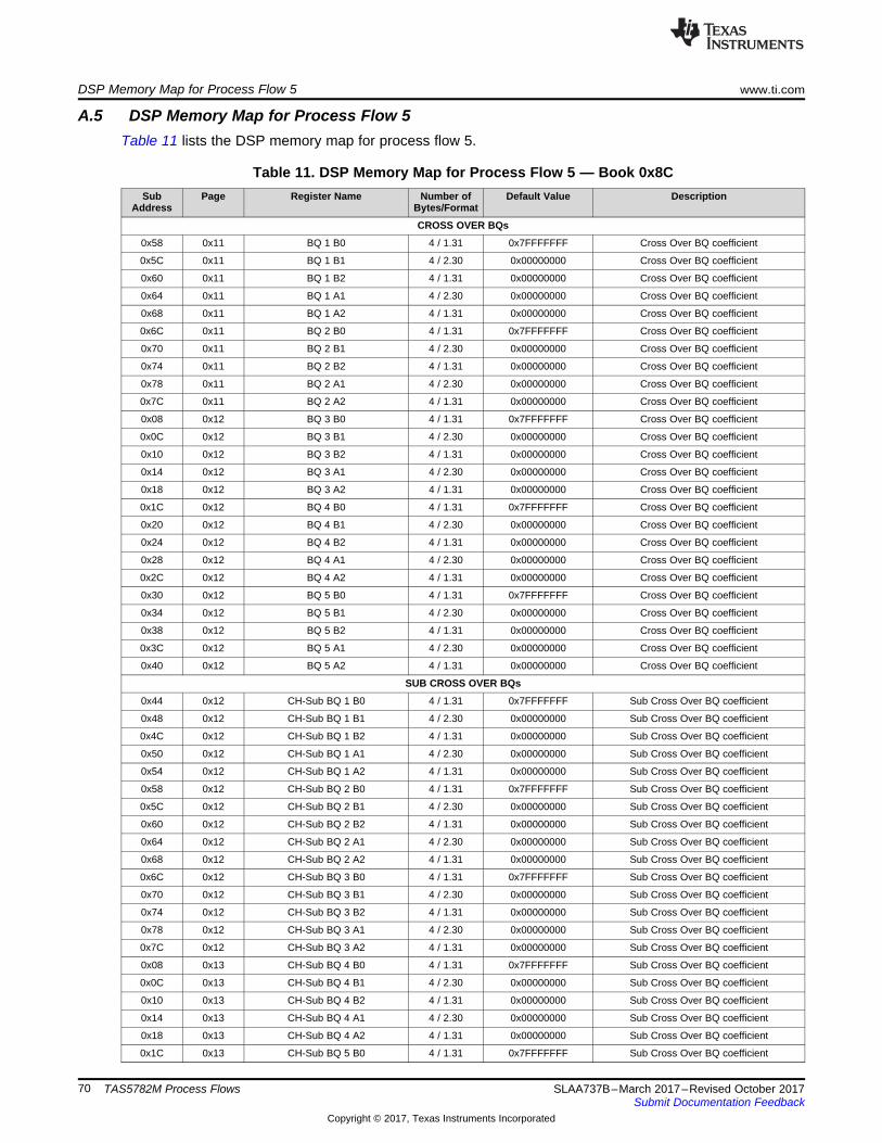
DSP Memory Map for Process Flow 5 www.ti.com
70 SLAA737B–March 2017–Revised October 2017Submit Documentation Feedback
Copyright © 2017, Texas Instruments Incorporated
TAS5782M Process Flows
A.5 DSP Memory Map for Process Flow 5Table 11 lists the DSP memory map for process flow 5.
Table 11. DSP Memory Map for Process Flow 5 — Book 0x8CSub
AddressPage Register Name Number of
Bytes/FormatDefault Value Description
CROSS OVER BQs
0x58 0x11 BQ 1 B0 4 / 1.31 0x7FFFFFFF Cross Over BQ coefficient
0x5C 0x11 BQ 1 B1 4 / 2.30 0x00000000 Cross Over BQ coefficient
0x60 0x11 BQ 1 B2 4 / 1.31 0x00000000 Cross Over BQ coefficient
0x64 0x11 BQ 1 A1 4 / 2.30 0x00000000 Cross Over BQ coefficient
0x68 0x11 BQ 1 A2 4 / 1.31 0x00000000 Cross Over BQ coefficient
0x6C 0x11 BQ 2 B0 4 / 1.31 0x7FFFFFFF Cross Over BQ coefficient
0x70 0x11 BQ 2 B1 4 / 2.30 0x00000000 Cross Over BQ coefficient
0x74 0x11 BQ 2 B2 4 / 1.31 0x00000000 Cross Over BQ coefficient
0x78 0x11 BQ 2 A1 4 / 2.30 0x00000000 Cross Over BQ coefficient
0x7C 0x11 BQ 2 A2 4 / 1.31 0x00000000 Cross Over BQ coefficient
0x08 0x12 BQ 3 B0 4 / 1.31 0x7FFFFFFF Cross Over BQ coefficient
0x0C 0x12 BQ 3 B1 4 / 2.30 0x00000000 Cross Over BQ coefficient
0x10 0x12 BQ 3 B2 4 / 1.31 0x00000000 Cross Over BQ coefficient
0x14 0x12 BQ 3 A1 4 / 2.30 0x00000000 Cross Over BQ coefficient
0x18 0x12 BQ 3 A2 4 / 1.31 0x00000000 Cross Over BQ coefficient
0x1C 0x12 BQ 4 B0 4 / 1.31 0x7FFFFFFF Cross Over BQ coefficient
0x20 0x12 BQ 4 B1 4 / 2.30 0x00000000 Cross Over BQ coefficient
0x24 0x12 BQ 4 B2 4 / 1.31 0x00000000 Cross Over BQ coefficient
0x28 0x12 BQ 4 A1 4 / 2.30 0x00000000 Cross Over BQ coefficient
0x2C 0x12 BQ 4 A2 4 / 1.31 0x00000000 Cross Over BQ coefficient
0x30 0x12 BQ 5 B0 4 / 1.31 0x7FFFFFFF Cross Over BQ coefficient
0x34 0x12 BQ 5 B1 4 / 2.30 0x00000000 Cross Over BQ coefficient
0x38 0x12 BQ 5 B2 4 / 1.31 0x00000000 Cross Over BQ coefficient
0x3C 0x12 BQ 5 A1 4 / 2.30 0x00000000 Cross Over BQ coefficient
0x40 0x12 BQ 5 A2 4 / 1.31 0x00000000 Cross Over BQ coefficient
SUB CROSS OVER BQs
0x44 0x12 CH-Sub BQ 1 B0 4 / 1.31 0x7FFFFFFF Sub Cross Over BQ coefficient
0x48 0x12 CH-Sub BQ 1 B1 4 / 2.30 0x00000000 Sub Cross Over BQ coefficient
0x4C 0x12 CH-Sub BQ 1 B2 4 / 1.31 0x00000000 Sub Cross Over BQ coefficient
0x50 0x12 CH-Sub BQ 1 A1 4 / 2.30 0x00000000 Sub Cross Over BQ coefficient
0x54 0x12 CH-Sub BQ 1 A2 4 / 1.31 0x00000000 Sub Cross Over BQ coefficient
0x58 0x12 CH-Sub BQ 2 B0 4 / 1.31 0x7FFFFFFF Sub Cross Over BQ coefficient
0x5C 0x12 CH-Sub BQ 2 B1 4 / 2.30 0x00000000 Sub Cross Over BQ coefficient
0x60 0x12 CH-Sub BQ 2 B2 4 / 1.31 0x00000000 Sub Cross Over BQ coefficient
0x64 0x12 CH-Sub BQ 2 A1 4 / 2.30 0x00000000 Sub Cross Over BQ coefficient
0x68 0x12 CH-Sub BQ 2 A2 4 / 1.31 0x00000000 Sub Cross Over BQ coefficient
0x6C 0x12 CH-Sub BQ 3 B0 4 / 1.31 0x7FFFFFFF Sub Cross Over BQ coefficient
0x70 0x12 CH-Sub BQ 3 B1 4 / 2.30 0x00000000 Sub Cross Over BQ coefficient
0x74 0x12 CH-Sub BQ 3 B2 4 / 1.31 0x00000000 Sub Cross Over BQ coefficient
0x78 0x12 CH-Sub BQ 3 A1 4 / 2.30 0x00000000 Sub Cross Over BQ coefficient
0x7C 0x12 CH-Sub BQ 3 A2 4 / 1.31 0x00000000 Sub Cross Over BQ coefficient
0x08 0x13 CH-Sub BQ 4 B0 4 / 1.31 0x7FFFFFFF Sub Cross Over BQ coefficient
0x0C 0x13 CH-Sub BQ 4 B1 4 / 2.30 0x00000000 Sub Cross Over BQ coefficient
0x10 0x13 CH-Sub BQ 4 B2 4 / 1.31 0x00000000 Sub Cross Over BQ coefficient
0x14 0x13 CH-Sub BQ 4 A1 4 / 2.30 0x00000000 Sub Cross Over BQ coefficient
0x18 0x13 CH-Sub BQ 4 A2 4 / 1.31 0x00000000 Sub Cross Over BQ coefficient
0x1C 0x13 CH-Sub BQ 5 B0 4 / 1.31 0x7FFFFFFF Sub Cross Over BQ coefficient

www.ti.com DSP Memory Map for Process Flow 5
71SLAA737B–March 2017–Revised October 2017Submit Documentation Feedback
Copyright © 2017, Texas Instruments Incorporated
TAS5782M Process Flows
Table 11. DSP Memory Map for Process Flow 5 — Book 0x8C (continued)Sub
AddressPage Register Name Number of
Bytes/FormatDefault Value Description
0x20 0x13 CH-Sub BQ 5 B1 4 / 2.30 0x00000000 Sub Cross Over BQ coefficient
0x24 0x13 CH-Sub BQ 5 B2 4 / 1.31 0x00000000 Sub Cross Over BQ coefficient
0x28 0x13 CH-Sub BQ 5 A1 4 / 2.30 0x00000000 Sub Cross Over BQ coefficient
0x2C 0x13 CH-Sub BQ 5 A2 4 / 1.31 0x00000000 Sub Cross Over BQ coefficient
DRC 1 BQ
0x30 0x13 BQ B0 4 / 1.31 0x7FFFFFFF DRC 1 BQ coefficient
0x34 0x13 BQ B1 4 / 2.30 0x00000000 DRC 1 BQ coefficient
0x38 0x13 BQ B2 4 / 1.31 0x00000000 DRC 1 BQ coefficient
0x3C 0x13 BQ A1 4 / 2.30 0x00000000 DRC 1 BQ coefficient
0x40 0x13 BQ A2 4 / 1.31 0x00000000 DRC 1 BQ coefficient
0x44 0x13 CH-Sub BQ B0 4 / 1.31 0x7FFFFFFF Sub DRC 1 BQ coefficient
0x48 0x13 CH-Sub BQ B1 4 / 2.30 0x00000000 Sub DRC 1 BQ coefficient
0x4C 0x13 CH-Sub BQ B2 4 / 1.31 0x00000000 Sub DRC 1 BQ coefficient
0x50 0x13 CH-Sub BQ A1 4 / 2.30 0x00000000 Sub DRC 1 BQ coefficient
0x54 0x13 CH-Sub BQ A2 4 / 1.31 0x00000000 Sub DRC 1 BQ coefficient
DRC 3 BQ
0x58 0x13 BQ B0 4 / 1.31 0x7FFFFFFF DRC 3 BQ coefficient
0x5C 0x13 BQ B1 4 / 2.30 0x00000000 DRC 3 BQ coefficient
0x60 0x13 BQ B2 4 / 1.31 0x00000000 DRC 3 BQ coefficient
0x64 0x13 BQ A1 4 / 2.30 0x00000000 DRC 3 BQ coefficient
0x68 0x13 BQ A2 4 / 1.31 0x00000000 DRC 3 BQ coefficient
0x6C 0x13 CH-Sub BQ B0 4 / 1.31 0x7FFFFFFF Sub DRC 3 BQ coefficient
0x70 0x13 CH-Sub BQ B1 4 / 2.30 0x00000000 Sub DRC 3 BQ coefficient
0x74 0x13 CH-Sub BQ B2 4 / 1.31 0x00000000 Sub DRC 3 BQ coefficient
0x78 0x13 CH-Sub BQ A1 4 / 2.30 0x00000000 Sub DRC 3 BQ coefficient
0x7C 0x13 CH-Sub BQ A2 4 / 1.31 0x00000000 Sub DRC 3 BQ coefficient
DRC 2 BQ
0x08 0x14 BQ 1 B0 4 / 1.31 0x7FFFFFFF DRC 2 BQ coefficient
0x0C 0x14 BQ 1 B1 4 / 2.30 0x00000000 DRC 2 BQ coefficient
0x10 0x14 BQ 1 B2 4 / 1.31 0x00000000 DRC 2 BQ coefficient
0x14 0x14 BQ 1 A1 4 / 2.30 0x00000000 DRC 2 BQ coefficient
0x18 0x14 BQ 1 A2 4 / 1.31 0x00000000 DRC 2 BQ coefficient
0x1C 0x14 BQ 2 B0 4 / 1.31 0x7FFFFFFF DRC 2 BQ coefficient
0x20 0x14 BQ 2 B1 4 / 2.30 0x00000000 DRC 2 BQ coefficient
0x24 0x14 BQ 2 B2 4 / 1.31 0x00000000 DRC 2 BQ coefficient
0x28 0x14 BQ 2 A1 4 / 2.30 0x00000000 DRC 2 BQ coefficient
0x2C 0x14 BQ 2 A2 4 / 1.31 0x00000000 DRC 2 BQ coefficient
0x30 0x14 CH-Sub BQ 1 B0 4 / 1.31 0x7FFFFFFF Sub DRC 2 BQ coefficient
0x34 0x14 CH-Sub BQ 1 B1 4 / 2.30 0x00000000 Sub DRC 2 BQ coefficient
0x38 0x14 CH-Sub BQ 1 B2 4 / 1.31 0x00000000 Sub DRC 2 BQ coefficient
0x3C 0x14 CH-Sub BQ 1 A1 4 / 2.30 0x00000000 Sub DRC 2 BQ coefficient
0x40 0x14 CH-Sub BQ 1 A2 4 / 1.31 0x00000000 Sub DRC 2 BQ coefficient
0x44 0x14 CH-Sub BQ 2 B0 4 / 1.31 0x7FFFFFFF Sub DRC 2 BQ coefficient
0x48 0x14 CH-Sub BQ 2 B1 4 / 2.30 0x00000000 Sub DRC 2 BQ coefficient
0x4C 0x14 CH-Sub BQ 2 B2 4 / 1.31 0x00000000 Sub DRC 2 BQ coefficient
0x50 0x14 CH-Sub BQ 2 A1 4 / 2.30 0x00000000 Sub DRC 2 BQ coefficient
0x54 0x14 CH-Sub BQ 2 A2 4 / 1.31 0x00000000 Sub DRC 2 BQ coefficient
DPEQ SENSE BQ
0x58 0x14 BQ 1 B0 4 / 1.31 0x7FFFFFFF DPEQ sense BQ coefficient
0x5C 0x14 BQ 1 B1 4 / 2.30 0x00000000 DPEQ sense BQ coefficient
0x60 0x14 BQ 1 B2 4 / 1.31 0x00000000 DPEQ sense BQ coefficient
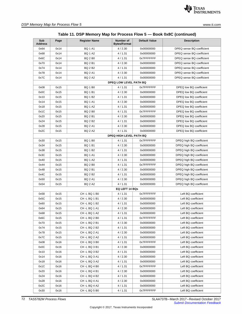
DSP Memory Map for Process Flow 5 www.ti.com
72 SLAA737B–March 2017–Revised October 2017Submit Documentation Feedback
Copyright © 2017, Texas Instruments Incorporated
TAS5782M Process Flows
Table 11. DSP Memory Map for Process Flow 5 — Book 0x8C (continued)Sub
AddressPage Register Name Number of
Bytes/FormatDefault Value Description
0x64 0x14 BQ 1 A1 4 / 2.30 0x00000000 DPEQ sense BQ coefficient
0x68 0x14 BQ 1 A2 4 / 1.31 0x00000000 DPEQ sense BQ coefficient
0x6C 0x14 BQ 2 B0 4 / 1.31 0x7FFFFFFF DPEQ sense BQ coefficient
0x70 0x14 BQ 2 B1 4 / 2.30 0x00000000 DPEQ sense BQ coefficient
0x74 0x14 BQ 2 B2 4 / 1.31 0x00000000 DPEQ sense BQ coefficient
0x78 0x14 BQ 2 A1 4 / 2.30 0x00000000 DPEQ sense BQ coefficient
0x7C 0x14 BQ 2 A2 4 / 1.31 0x00000000 DPEQ sense BQ coefficient
DPEQ LOW LEVEL PATH BQ
0x08 0x15 BQ 1 B0 4 / 1.31 0x7FFFFFFF DPEQ low BQ coefficient
0x0C 0x15 BQ 1 B1 4 / 2.30 0x00000000 DPEQ low BQ coefficient
0x10 0x15 BQ 1 B2 4 / 1.31 0x00000000 DPEQ low BQ coefficient
0x14 0x15 BQ 1 A1 4 / 2.30 0x00000000 DPEQ low BQ coefficient
0x18 0x15 BQ 1 A2 4 / 1.31 0x00000000 DPEQ low BQ coefficient
0x1C 0x15 BQ 2 B0 4 / 1.31 0x7FFFFFFF DPEQ low BQ coefficient
0x20 0x15 BQ 2 B1 4 / 2.30 0x00000000 DPEQ low BQ coefficient
0x24 0x15 BQ 2 B2 4 / 1.31 0x00000000 DPEQ low BQ coefficient
0x28 0x15 BQ 2 A1 4 / 2.30 0x00000000 DPEQ low BQ coefficient
0x2C 0x15 BQ 2 A2 4 / 1.31 0x00000000 DPEQ low BQ coefficient
DPEQ HIGH LEVEL PATH BQ
0x30 0x15 BQ 1 B0 4 / 1.31 0x7FFFFFFF DPEQ high BQ coefficient
0x34 0x15 BQ 1 B1 4 / 2.30 0x00000000 DPEQ high BQ coefficient
0x38 0x15 BQ 1 B2 4 / 1.31 0x00000000 DPEQ high BQ coefficient
0x3C 0x15 BQ 1 A1 4 / 2.30 0x00000000 DPEQ high BQ coefficient
0x40 0x15 BQ 1 A2 4 / 1.31 0x00000000 DPEQ high BQ coefficient
0x44 0x15 BQ 2 B0 4 / 1.31 0x7FFFFFFF DPEQ high BQ coefficient
0x48 0x15 BQ 2 B1 4 / 2.30 0x00000000 DPEQ high BQ coefficient
0x4C 0x15 BQ 2 B2 4 / 1.31 0x00000000 DPEQ high BQ coefficient
0x50 0x15 BQ 2 A1 4 / 2.30 0x00000000 DPEQ high BQ coefficient
0x54 0x15 BQ 2 A2 4 / 1.31 0x00000000 DPEQ high BQ coefficient
EQ LEFT 14 BQs
0x58 0x15 CH -L BQ 1 B0 4 / 1.31 0x7FFFFFFF Left BQ coefficient
0x5C 0x15 CH -L BQ 1 B1 4 / 2.30 0x00000000 Left BQ coefficient
0x60 0x15 CH -L BQ 1 B2 4 / 1.31 0x00000000 Left BQ coefficient
0x64 0x15 CH -L BQ 1 A1 4 / 2.30 0x00000000 Left BQ coefficient
0x68 0x15 CH -L BQ 1 A2 4 / 1.31 0x00000000 Left BQ coefficient
0x6C 0x15 CH -L BQ 2 B0 4 / 1.31 0x7FFFFFFF Left BQ coefficient
0x70 0x15 CH -L BQ 2 B1 4 / 2.30 0x00000000 Left BQ coefficient
0x74 0x15 CH -L BQ 2 B2 4 / 1.31 0x00000000 Left BQ coefficient
0x78 0x15 CH -L BQ 2 A1 4 / 2.30 0x00000000 Left BQ coefficient
0x7C 0x15 CH -L BQ 2 A2 4 / 1.31 0x00000000 Left BQ coefficient
0x08 0x16 CH -L BQ 3 B0 4 / 1.31 0x7FFFFFFF Left BQ coefficient
0x0C 0x16 CH -L BQ 3 B1 4 / 2.30 0x00000000 Left BQ coefficient
0x10 0x16 CH -L BQ 3 B2 4 / 1.31 0x00000000 Left BQ coefficient
0x14 0x16 CH -L BQ 3 A1 4 / 2.30 0x00000000 Left BQ coefficient
0x18 0x16 CH -L BQ 3 A2 4 / 1.31 0x00000000 Left BQ coefficient
0x1C 0x16 CH -L BQ 4 B0 4 / 1.31 0x7FFFFFFF Left BQ coefficient
0x20 0x16 CH -L BQ 4 B1 4 / 2.30 0x00000000 Left BQ coefficient
0x24 0x16 CH -L BQ 4 B2 4 / 1.31 0x00000000 Left BQ coefficient
0x28 0x16 CH -L BQ 4 A1 4 / 2.30 0x00000000 Left BQ coefficient
0x2C 0x16 CH -L BQ 4 A2 4 / 1.31 0x00000000 Left BQ coefficient
0x30 0x16 CH -L BQ 5 B0 4 / 1.31 0x7FFFFFFF Left BQ coefficient
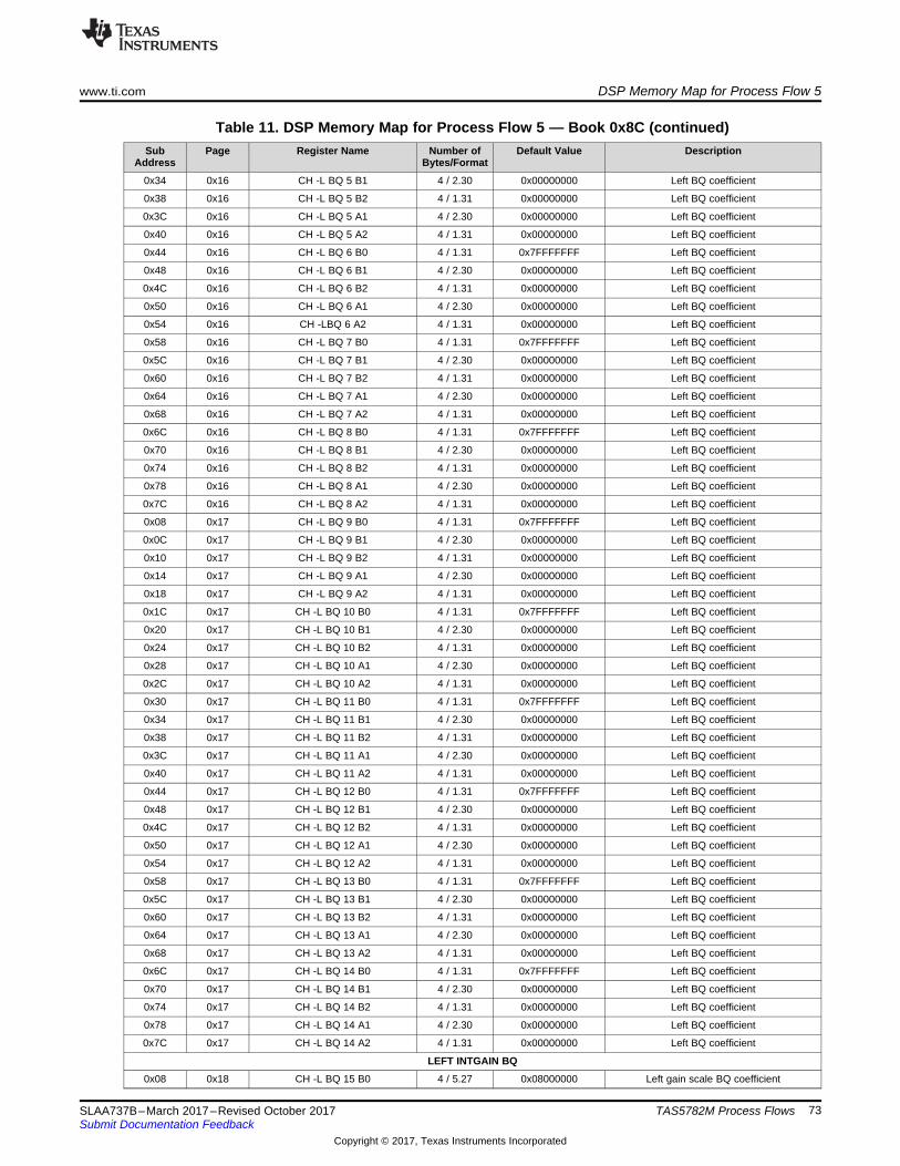
www.ti.com DSP Memory Map for Process Flow 5
73SLAA737B–March 2017–Revised October 2017Submit Documentation Feedback
Copyright © 2017, Texas Instruments Incorporated
TAS5782M Process Flows
Table 11. DSP Memory Map for Process Flow 5 — Book 0x8C (continued)Sub
AddressPage Register Name Number of
Bytes/FormatDefault Value Description
0x34 0x16 CH -L BQ 5 B1 4 / 2.30 0x00000000 Left BQ coefficient
0x38 0x16 CH -L BQ 5 B2 4 / 1.31 0x00000000 Left BQ coefficient
0x3C 0x16 CH -L BQ 5 A1 4 / 2.30 0x00000000 Left BQ coefficient
0x40 0x16 CH -L BQ 5 A2 4 / 1.31 0x00000000 Left BQ coefficient
0x44 0x16 CH -L BQ 6 B0 4 / 1.31 0x7FFFFFFF Left BQ coefficient
0x48 0x16 CH -L BQ 6 B1 4 / 2.30 0x00000000 Left BQ coefficient
0x4C 0x16 CH -L BQ 6 B2 4 / 1.31 0x00000000 Left BQ coefficient
0x50 0x16 CH -L BQ 6 A1 4 / 2.30 0x00000000 Left BQ coefficient
0x54 0x16 CH -LBQ 6 A2 4 / 1.31 0x00000000 Left BQ coefficient
0x58 0x16 CH -L BQ 7 B0 4 / 1.31 0x7FFFFFFF Left BQ coefficient
0x5C 0x16 CH -L BQ 7 B1 4 / 2.30 0x00000000 Left BQ coefficient
0x60 0x16 CH -L BQ 7 B2 4 / 1.31 0x00000000 Left BQ coefficient
0x64 0x16 CH -L BQ 7 A1 4 / 2.30 0x00000000 Left BQ coefficient
0x68 0x16 CH -L BQ 7 A2 4 / 1.31 0x00000000 Left BQ coefficient
0x6C 0x16 CH -L BQ 8 B0 4 / 1.31 0x7FFFFFFF Left BQ coefficient
0x70 0x16 CH -L BQ 8 B1 4 / 2.30 0x00000000 Left BQ coefficient
0x74 0x16 CH -L BQ 8 B2 4 / 1.31 0x00000000 Left BQ coefficient
0x78 0x16 CH -L BQ 8 A1 4 / 2.30 0x00000000 Left BQ coefficient
0x7C 0x16 CH -L BQ 8 A2 4 / 1.31 0x00000000 Left BQ coefficient
0x08 0x17 CH -L BQ 9 B0 4 / 1.31 0x7FFFFFFF Left BQ coefficient
0x0C 0x17 CH -L BQ 9 B1 4 / 2.30 0x00000000 Left BQ coefficient
0x10 0x17 CH -L BQ 9 B2 4 / 1.31 0x00000000 Left BQ coefficient
0x14 0x17 CH -L BQ 9 A1 4 / 2.30 0x00000000 Left BQ coefficient
0x18 0x17 CH -L BQ 9 A2 4 / 1.31 0x00000000 Left BQ coefficient
0x1C 0x17 CH -L BQ 10 B0 4 / 1.31 0x7FFFFFFF Left BQ coefficient
0x20 0x17 CH -L BQ 10 B1 4 / 2.30 0x00000000 Left BQ coefficient
0x24 0x17 CH -L BQ 10 B2 4 / 1.31 0x00000000 Left BQ coefficient
0x28 0x17 CH -L BQ 10 A1 4 / 2.30 0x00000000 Left BQ coefficient
0x2C 0x17 CH -L BQ 10 A2 4 / 1.31 0x00000000 Left BQ coefficient
0x30 0x17 CH -L BQ 11 B0 4 / 1.31 0x7FFFFFFF Left BQ coefficient
0x34 0x17 CH -L BQ 11 B1 4 / 2.30 0x00000000 Left BQ coefficient
0x38 0x17 CH -L BQ 11 B2 4 / 1.31 0x00000000 Left BQ coefficient
0x3C 0x17 CH -L BQ 11 A1 4 / 2.30 0x00000000 Left BQ coefficient
0x40 0x17 CH -L BQ 11 A2 4 / 1.31 0x00000000 Left BQ coefficient
0x44 0x17 CH -L BQ 12 B0 4 / 1.31 0x7FFFFFFF Left BQ coefficient
0x48 0x17 CH -L BQ 12 B1 4 / 2.30 0x00000000 Left BQ coefficient
0x4C 0x17 CH -L BQ 12 B2 4 / 1.31 0x00000000 Left BQ coefficient
0x50 0x17 CH -L BQ 12 A1 4 / 2.30 0x00000000 Left BQ coefficient
0x54 0x17 CH -L BQ 12 A2 4 / 1.31 0x00000000 Left BQ coefficient
0x58 0x17 CH -L BQ 13 B0 4 / 1.31 0x7FFFFFFF Left BQ coefficient
0x5C 0x17 CH -L BQ 13 B1 4 / 2.30 0x00000000 Left BQ coefficient
0x60 0x17 CH -L BQ 13 B2 4 / 1.31 0x00000000 Left BQ coefficient
0x64 0x17 CH -L BQ 13 A1 4 / 2.30 0x00000000 Left BQ coefficient
0x68 0x17 CH -L BQ 13 A2 4 / 1.31 0x00000000 Left BQ coefficient
0x6C 0x17 CH -L BQ 14 B0 4 / 1.31 0x7FFFFFFF Left BQ coefficient
0x70 0x17 CH -L BQ 14 B1 4 / 2.30 0x00000000 Left BQ coefficient
0x74 0x17 CH -L BQ 14 B2 4 / 1.31 0x00000000 Left BQ coefficient
0x78 0x17 CH -L BQ 14 A1 4 / 2.30 0x00000000 Left BQ coefficient
0x7C 0x17 CH -L BQ 14 A2 4 / 1.31 0x00000000 Left BQ coefficient
LEFT INTGAIN BQ
0x08 0x18 CH -L BQ 15 B0 4 / 5.27 0x08000000 Left gain scale BQ coefficient
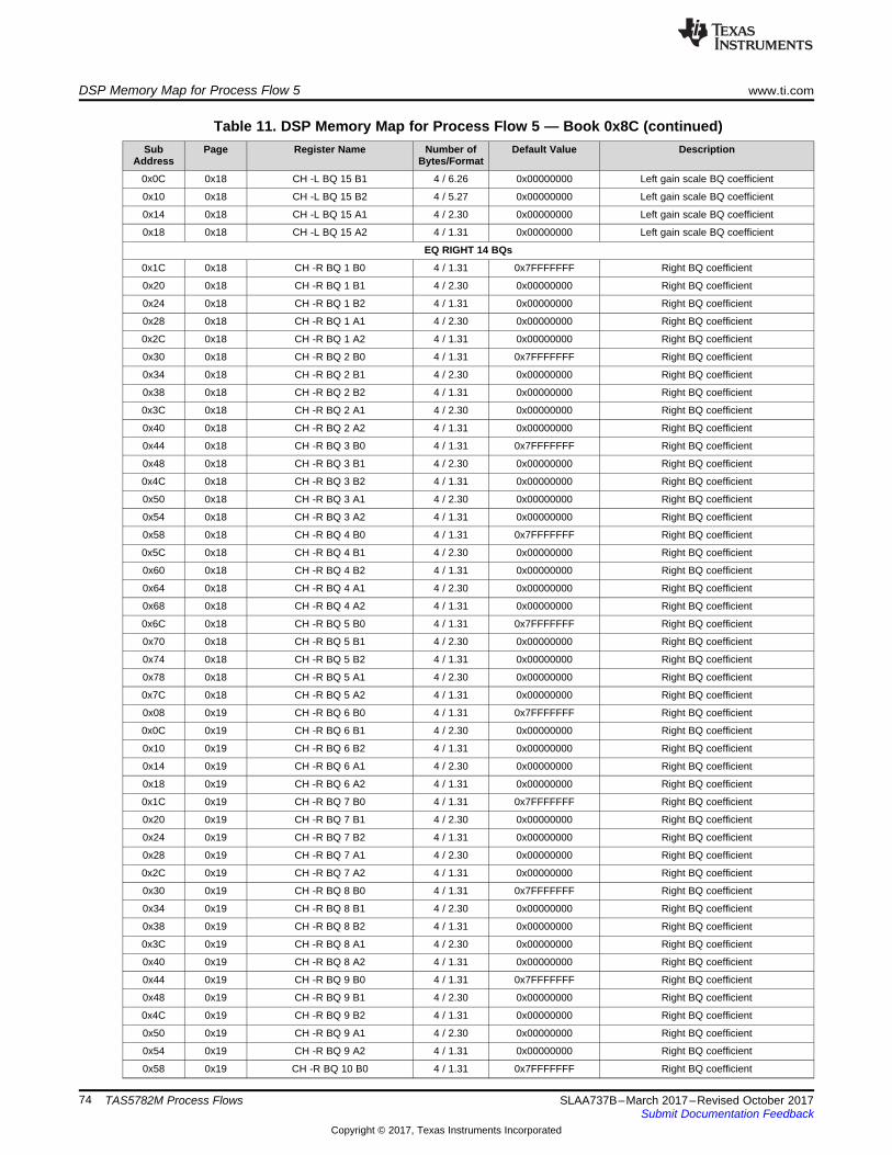
DSP Memory Map for Process Flow 5 www.ti.com
74 SLAA737B–March 2017–Revised October 2017Submit Documentation Feedback
Copyright © 2017, Texas Instruments Incorporated
TAS5782M Process Flows
Table 11. DSP Memory Map for Process Flow 5 — Book 0x8C (continued)Sub
AddressPage Register Name Number of
Bytes/FormatDefault Value Description
0x0C 0x18 CH -L BQ 15 B1 4 / 6.26 0x00000000 Left gain scale BQ coefficient
0x10 0x18 CH -L BQ 15 B2 4 / 5.27 0x00000000 Left gain scale BQ coefficient
0x14 0x18 CH -L BQ 15 A1 4 / 2.30 0x00000000 Left gain scale BQ coefficient
0x18 0x18 CH -L BQ 15 A2 4 / 1.31 0x00000000 Left gain scale BQ coefficient
EQ RIGHT 14 BQs
0x1C 0x18 CH -R BQ 1 B0 4 / 1.31 0x7FFFFFFF Right BQ coefficient
0x20 0x18 CH -R BQ 1 B1 4 / 2.30 0x00000000 Right BQ coefficient
0x24 0x18 CH -R BQ 1 B2 4 / 1.31 0x00000000 Right BQ coefficient
0x28 0x18 CH -R BQ 1 A1 4 / 2.30 0x00000000 Right BQ coefficient
0x2C 0x18 CH -R BQ 1 A2 4 / 1.31 0x00000000 Right BQ coefficient
0x30 0x18 CH -R BQ 2 B0 4 / 1.31 0x7FFFFFFF Right BQ coefficient
0x34 0x18 CH -R BQ 2 B1 4 / 2.30 0x00000000 Right BQ coefficient
0x38 0x18 CH -R BQ 2 B2 4 / 1.31 0x00000000 Right BQ coefficient
0x3C 0x18 CH -R BQ 2 A1 4 / 2.30 0x00000000 Right BQ coefficient
0x40 0x18 CH -R BQ 2 A2 4 / 1.31 0x00000000 Right BQ coefficient
0x44 0x18 CH -R BQ 3 B0 4 / 1.31 0x7FFFFFFF Right BQ coefficient
0x48 0x18 CH -R BQ 3 B1 4 / 2.30 0x00000000 Right BQ coefficient
0x4C 0x18 CH -R BQ 3 B2 4 / 1.31 0x00000000 Right BQ coefficient
0x50 0x18 CH -R BQ 3 A1 4 / 2.30 0x00000000 Right BQ coefficient
0x54 0x18 CH -R BQ 3 A2 4 / 1.31 0x00000000 Right BQ coefficient
0x58 0x18 CH -R BQ 4 B0 4 / 1.31 0x7FFFFFFF Right BQ coefficient
0x5C 0x18 CH -R BQ 4 B1 4 / 2.30 0x00000000 Right BQ coefficient
0x60 0x18 CH -R BQ 4 B2 4 / 1.31 0x00000000 Right BQ coefficient
0x64 0x18 CH -R BQ 4 A1 4 / 2.30 0x00000000 Right BQ coefficient
0x68 0x18 CH -R BQ 4 A2 4 / 1.31 0x00000000 Right BQ coefficient
0x6C 0x18 CH -R BQ 5 B0 4 / 1.31 0x7FFFFFFF Right BQ coefficient
0x70 0x18 CH -R BQ 5 B1 4 / 2.30 0x00000000 Right BQ coefficient
0x74 0x18 CH -R BQ 5 B2 4 / 1.31 0x00000000 Right BQ coefficient
0x78 0x18 CH -R BQ 5 A1 4 / 2.30 0x00000000 Right BQ coefficient
0x7C 0x18 CH -R BQ 5 A2 4 / 1.31 0x00000000 Right BQ coefficient
0x08 0x19 CH -R BQ 6 B0 4 / 1.31 0x7FFFFFFF Right BQ coefficient
0x0C 0x19 CH -R BQ 6 B1 4 / 2.30 0x00000000 Right BQ coefficient
0x10 0x19 CH -R BQ 6 B2 4 / 1.31 0x00000000 Right BQ coefficient
0x14 0x19 CH -R BQ 6 A1 4 / 2.30 0x00000000 Right BQ coefficient
0x18 0x19 CH -R BQ 6 A2 4 / 1.31 0x00000000 Right BQ coefficient
0x1C 0x19 CH -R BQ 7 B0 4 / 1.31 0x7FFFFFFF Right BQ coefficient
0x20 0x19 CH -R BQ 7 B1 4 / 2.30 0x00000000 Right BQ coefficient
0x24 0x19 CH -R BQ 7 B2 4 / 1.31 0x00000000 Right BQ coefficient
0x28 0x19 CH -R BQ 7 A1 4 / 2.30 0x00000000 Right BQ coefficient
0x2C 0x19 CH -R BQ 7 A2 4 / 1.31 0x00000000 Right BQ coefficient
0x30 0x19 CH -R BQ 8 B0 4 / 1.31 0x7FFFFFFF Right BQ coefficient
0x34 0x19 CH -R BQ 8 B1 4 / 2.30 0x00000000 Right BQ coefficient
0x38 0x19 CH -R BQ 8 B2 4 / 1.31 0x00000000 Right BQ coefficient
0x3C 0x19 CH -R BQ 8 A1 4 / 2.30 0x00000000 Right BQ coefficient
0x40 0x19 CH -R BQ 8 A2 4 / 1.31 0x00000000 Right BQ coefficient
0x44 0x19 CH -R BQ 9 B0 4 / 1.31 0x7FFFFFFF Right BQ coefficient
0x48 0x19 CH -R BQ 9 B1 4 / 2.30 0x00000000 Right BQ coefficient
0x4C 0x19 CH -R BQ 9 B2 4 / 1.31 0x00000000 Right BQ coefficient
0x50 0x19 CH -R BQ 9 A1 4 / 2.30 0x00000000 Right BQ coefficient
0x54 0x19 CH -R BQ 9 A2 4 / 1.31 0x00000000 Right BQ coefficient
0x58 0x19 CH -R BQ 10 B0 4 / 1.31 0x7FFFFFFF Right BQ coefficient

www.ti.com DSP Memory Map for Process Flow 5
75SLAA737B–March 2017–Revised October 2017Submit Documentation Feedback
Copyright © 2017, Texas Instruments Incorporated
TAS5782M Process Flows
Table 11. DSP Memory Map for Process Flow 5 — Book 0x8C (continued)Sub
AddressPage Register Name Number of
Bytes/FormatDefault Value Description
0x5C 0x19 CH -R BQ 10 B1 4 / 2.30 0x00000000 Right BQ coefficient
0x60 0x19 CH -R BQ 10 B2 4 / 1.31 0x00000000 Right BQ coefficient
0x64 0x19 CH -R BQ 10 A1 4 / 2.30 0x00000000 Right BQ coefficient
0x68 0x19 CH -R BQ 10 A2 4 / 1.31 0x00000000 Right BQ coefficient
0x6C 0x19 CH -R BQ 11 B0 4 / 1.31 0x7FFFFFFF Right BQ coefficient
0x70 0x19 CH -R BQ 11 B1 4 / 2.30 0x00000000 Right BQ coefficient
0x74 0x19 CH -R BQ 11 B2 4 / 1.31 0x00000000 Right BQ coefficient
0x78 0x19 CH -R BQ 11 A1 4 / 2.30 0x00000000 Right BQ coefficient
0x7C 0x19 CH -R BQ 11 A2 4 / 1.31 0x00000000 Right BQ coefficient
0x08 0x1A CH -R BQ 12 B0 4 / 1.31 0x7FFFFFFF Right BQ coefficient
0x0C 0x1A CH -R BQ 12 B1 4 / 2.30 0x00000000 Right BQ coefficient
0x10 0x1A CH -R BQ 12 B2 4 / 1.31 0x00000000 Right BQ coefficient
0x14 0x1A CH -R BQ 12 A1 4 / 2.30 0x00000000 Right BQ coefficient
0x18 0x1A CH -R BQ 12 A2 4 / 1.31 0x00000000 Right BQ coefficient
0x1C 0x1A CH -R BQ 13 B0 4 / 1.31 0x7FFFFFFF Right BQ coefficient
0x20 0x1A CH -R BQ 13 B1 4 / 2.30 0x00000000 Right BQ coefficient
0x24 0x1A CH -R BQ 13 B2 4 / 1.31 0x00000000 Right BQ coefficient
0x28 0x1A CH -R BQ 13 A1 4 / 2.30 0x00000000 Right BQ coefficient
0x2C 0x1A CH -R BQ 13 A2 4 / 1.31 0x00000000 Right BQ coefficient
0x30 0x1A CH -R BQ 14 B0 4 / 1.31 0x7FFFFFFF Right BQ coefficient
0x34 0x1A CH -R BQ 14 B1 4 / 2.30 0x00000000 Right BQ coefficient
0x38 0x1A CH -R BQ 14 B2 4 / 1.31 0x00000000 Right BQ coefficient
0x3C 0x1A CH -R BQ 14 A1 4 / 2.30 0x00000000 Right BQ coefficient
0x40 0x1A CH -R BQ 14 A2 4 / 1.31 0x00000000 Right BQ coefficient
RIGHT INTGAIN BQ
0x44 0x1A CH -R BQ 15 B0 4 / 5.27 0x08000000 Right gain scale BQ coefficient
0x48 0x1A CH -R BQ 15 B1 4 / 6.26 0x00000000 Right gain scale BQ coefficient
0x4C 0x1A CH -R BQ 15 B2 4 / 5.27 0x00000000 Right gain scale BQ coefficient
0x50 0x1A CH -R BQ 15 A1 4 / 2.30 0x00000000 Right gain scale BQ coefficient
0x54 0x1A CH -R BQ 15 A2 4 / 1.31 0x00000000 Right gain scale BQ coefficient
VOLUME ALPHA FILTER
0x58 0x1A Softening Filter Alpha 4 / 1.31 0x00A7264A Volume time constant
PHASE OPTIMIZER
0x60 0x1A Delay Left 4 / 32.0 0x00000000 Left Channel Phase Optimizer
0x64 0x1A Delay Right 4 / 32.0 0x00000000 Right Channel Phase Optimizer
0x68 0x1A Delay Sub 4 / 32.0 0x00000000 Sub Channel Phase Optimizer
MAIN DRC 1
0x6C 0x1A DRC1 Energy 4 / 1.31 0x7FFFFFFF DRC1 Energy Time constant
0x70 0x1A DRC1 Attack 4 / 1.31 0x7FFFFFFF DRC1 Attack Time constant
0x74 0x1A DRC1 Decay 4 / 1.31 0x7FFFFFFF DRC1 Decay Time constant
0x78 0x1A K0_1 4 / 9.23 0x00000000 DRC1 Region 1 Slope (comp/Exp)
0x7C 0x1A K1_1 4 / 9.23 0x00000000 DRC1 Region 2 Slope (comp/Exp)
0x08 0x1B K2_1 4 / 9.23 0x00000000 DRC1 Region 3 Slope (comp/Exp)
0x0C 0x1B T1_1 4 / 9.23 0xE7000000 DRC1 Threshold 1
0x10 0x1B T2_1 4 / 9.23 0xFE800000 DRC1 Threshold 2
0x14 0x1B off1_1 4 / 9.23 0x00000000 DRC1 Offset 1
0x18 0x1B off2_1 4 / 9.23 0x00000000 DRC1 Offset 2
MAIN DRC 2
0x1C 0x1B DRC2 Energy 4 / 1.31 0x7FFFFFFF DRC2 Energy Time constant
0x20 0x1B DRC2 Attack 4 / 1.31 0x7FFFFFFF DRC2 Attack Time constant
0x24 0x1B DRC2 Decay 4 / 1.31 0x7FFFFFFF DRC2 Decay Time constant

DSP Memory Map for Process Flow 5 www.ti.com
76 SLAA737B–March 2017–Revised October 2017Submit Documentation Feedback
Copyright © 2017, Texas Instruments Incorporated
TAS5782M Process Flows
Table 11. DSP Memory Map for Process Flow 5 — Book 0x8C (continued)Sub
AddressPage Register Name Number of
Bytes/FormatDefault Value Description
0x28 0x1B k0_2 4 / 9.23 0x00000000 DRC2 Region 1 Slope (comp/Exp)
0x2C 0x1B k1_2 4 / 9.23 0x00000000 DRC2 Region 2 Slope (comp/Exp)
0x30 0x1B k2_2 4 / 9.23 0x00000000 DRC2 Region 3 Slope (comp/Exp)
0x34 0x1B t1_2 4 / 9.23 0xE7000000 DRC2 Threshold 1
0x38 0x1B t2_2 4 / 9.23 0xFE800000 DRC2 Threshold 2
0x3C 0x1B off1_2 4 / 9.23 0x00000000 DRC2 Offset 1
0x40 0x1B off2_2 4 / 9.23 0x00000000 DRC2 Offset 2
MAIN DRC 3
0x44 0x1B DRC3 Energy 4 / 1.31 0x7FFFFFFF DRC3 Energy Time constant
0x48 0x1B DRC3 Attack 4 / 1.31 0x7FFFFFFF DRC3 Attack Time constant
0x4C 0x1B DRC3 Decay 4 / 1.31 0x7FFFFFFF DRC3 Decay Time constant
0x50 0x1B k0_3 4 / 9.23 0x00000000 DRC3 Region 1 Slope (comp/Exp)
0x54 0x1B k1_3 4 / 9.23 0x00000000 DRC3 Region 2 Slope (comp/Exp)
0x58 0x1B k1_3 4 / 9.23 0x00000000 DRC3 Region 3 Slope (comp/Exp)
0x5C 0x1B t1_3 4 / 9.23 0xE7000000 DRC3 Threshold 1
0x60 0x1B t2_3 4 / 9.23 0xFE800000 DRC3 Threshold 2
0x64 0x1B off1_3 4 / 9.23 0x00000000 DRC3 Offset 1
0x68 0x1B off2_3 4 / 9.23 0x00000000 DRC3 Offset 2
SUB DRC 1
0x6C 0x1B CH-Sub DRC1 Energy 4 / 1.31 0x7FFFFFFF Sub Channel DRC1 Energy Time constant
0x70 0x1B CH-Sub DRC1 Attack 4 / 1.31 0x7FFFFFFF Sub Channel DRC1 Attack Time constant
0x74 0x1B CH-Sub DRC1 Decay 4 / 1.31 0x7FFFFFFF Sub Channel DRC1 Decay Time constant
0x78 0x1B CH-Sub K0_1 4 / 9.23 0x00000000 Sub Channel DRC1 Region 1 Slope(comp/Exp)
0x7C 0x1B CH-Sub K1_1 4 / 9.23 0x00000000 Sub Channel DRC1 Region 2 Slope(comp/Exp)
0x08 0x1C CH-Sub K2_1 4 / 9.23 0x00000000 Sub Channel DRC1 Region 3 Slope(comp/Exp)
0x0C 0x1C CH-Sub T1_1 4 / 9.23 0xE7000000 Sub Channel DRC1 Threshold 1
0x10 0x1C CH-Sub T2_1 4 / 9.23 0xFE800000 Sub Channel DRC1 Threshold 2
0x14 0x1C CH-Sub off1_1 4 / 9.23 0x00000000 Sub Channel DRC1 Offset 1
0x18 0x1C CH-Sub off2_1 4 / 9.23 0x00000000 Sub Channel DRC1 Offset 2
SUB DRC 2
0x1C 0x1C CH-Sub DRC2 Energy 4 / 1.31 0x7FFFFFFF Sub Channel DRC2 Energy Time constant
0x20 0x1C CH-Sub DRC2 Attack 4 / 1.31 0x7FFFFFFF Sub Channel DRC2 Attack Time constant
0x24 0x1C CH-Sub DRC2 Decay 4 / 1.31 0x7FFFFFFF Sub Channel DRC2 Decay Time constant
0x28 0x1C CH-Sub k0_2 4 / 9.23 0x00000000 Sub Channel DRC2 Region 1 Slope(comp/Exp)
0x2C 0x1C CH-Sub k1_2 4 / 9.23 0x00000000 Sub Channel DRC2 Region 2 Slope(comp/Exp)
0x30 0x1C CH-Sub k2_2 4 / 9.23 0x00000000 Sub Channel DRC2 Region 3 Slope(comp/Exp)
0x34 0x1C CH-Sub t1_2 4 / 9.23 0xE7000000 Sub Channel DRC2 Threshold 1
0x38 0x1C CH-Sub t2_2 4 / 9.23 0xFE800000 Sub Channel DRC2 Threshold 2
0x3C 0x1C CH-Sub off1_2 4 / 9.23 0x00000000 Sub Channel DRC2 Offset 1
0x40 0x1C CH-Sub off2_2 4 / 9.23 0x00000000 Sub Channel DRC2 Offset 2
SUB DRC 3
0x44 0x1C CH-Sub DRC3 Energy 4 / 1.31 0x7FFFFFFF Sub Channel DRC3 Energy Time constant
0x48 0x1C CH-Sub DRC3 Attack 4 / 1.31 0x7FFFFFFF Sub Channel DRC3 Attack Time constant
0x4C 0x1C CH-Sub DRC3 Decay 4 / 1.31 0x7FFFFFFF Sub Channel DRC3 Decay Time constant
0x50 0x1C CH-Sub k0_3 4 / 9.23 0x00000000 Sub Channel DRC3 Region 1 Slope(comp/Exp)
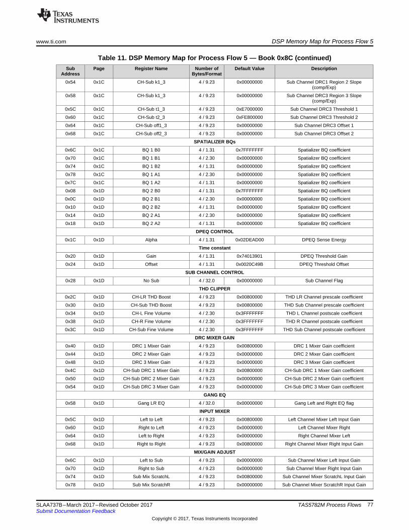
www.ti.com DSP Memory Map for Process Flow 5
77SLAA737B–March 2017–Revised October 2017Submit Documentation Feedback
Copyright © 2017, Texas Instruments Incorporated
TAS5782M Process Flows
Table 11. DSP Memory Map for Process Flow 5 — Book 0x8C (continued)Sub
AddressPage Register Name Number of
Bytes/FormatDefault Value Description
0x54 0x1C CH-Sub k1_3 4 / 9.23 0x00000000 Sub Channel DRC1 Region 2 Slope(comp/Exp)
0x58 0x1C CH-Sub k1_3 4 / 9.23 0x00000000 Sub Channel DRC3 Region 3 Slope(comp/Exp)
0x5C 0x1C CH-Sub t1_3 4 / 9.23 0xE7000000 Sub Channel DRC3 Threshold 1
0x60 0x1C CH-Sub t2_3 4 / 9.23 0xFE800000 Sub Channel DRC3 Threshold 2
0x64 0x1C CH-Sub off1_3 4 / 9.23 0x00000000 Sub Channel DRC3 Offset 1
0x68 0x1C CH-Sub off2_3 4 / 9.23 0x00000000 Sub Channel DRC3 Offset 2
SPATIALIZER BQs
0x6C 0x1C BQ 1 B0 4 / 1.31 0x7FFFFFFF Spatializer BQ coefficient
0x70 0x1C BQ 1 B1 4 / 2.30 0x00000000 Spatializer BQ coefficient
0x74 0x1C BQ 1 B2 4 / 1.31 0x00000000 Spatializer BQ coefficient
0x78 0x1C BQ 1 A1 4 / 2.30 0x00000000 Spatializer BQ coefficient
0x7C 0x1C BQ 1 A2 4 / 1.31 0x00000000 Spatializer BQ coefficient
0x08 0x1D BQ 2 B0 4 / 1.31 0x7FFFFFFF Spatializer BQ coefficient
0x0C 0x1D BQ 2 B1 4 / 2.30 0x00000000 Spatializer BQ coefficient
0x10 0x1D BQ 2 B2 4 / 1.31 0x00000000 Spatializer BQ coefficient
0x14 0x1D BQ 2 A1 4 / 2.30 0x00000000 Spatializer BQ coefficient
0x18 0x1D BQ 2 A2 4 / 1.31 0x00000000 Spatializer BQ coefficient
DPEQ CONTROL
0x1C 0x1D Alpha 4 / 1.31 0x02DEAD00 DPEQ Sense Energy
Time constant
0x20 0x1D Gain 4 / 1.31 0x74013901 DPEQ Threshold Gain
0x24 0x1D Offset 4 / 1.31 0x0020C49B DPEQ Threshold Offset
SUB CHANNEL CONTROL
0x28 0x1D No Sub 4 / 32.0 0x00000000 Sub Channel Flag
THD CLIPPER
0x2C 0x1D CH-LR THD Boost 4 / 9.23 0x00800000 THD LR Channel prescale coefficient
0x30 0x1D CH-Sub THD Boost 4 / 9.23 0x00800000 THD Sub Channel prescale coefficient
0x34 0x1D CH-L Fine Volume 4 / 2.30 0x3FFFFFFF THD L Channel postscale coefficient
0x38 0x1D CH-R Fine Volume 4 / 2.30 0x3FFFFFFF THD R Channel postscale coefficient
0x3C 0x1D CH-Sub Fine Volume 4 / 2.30 0x3FFFFFFF THD Sub Channel postscale coefficient
DRC MIXER GAIN
0x40 0x1D DRC 1 Mixer Gain 4 / 9.23 0x00800000 DRC 1 Mixer Gain coefficient
0x44 0x1D DRC 2 Mixer Gain 4 / 9.23 0x00000000 DRC 2 Mixer Gain coefficient
0x48 0x1D DRC 3 Mixer Gain 4 / 9.23 0x00000000 DRC 3 Mixer Gain coefficient
0x4C 0x1D CH-Sub DRC 1 Mixer Gain 4 / 9.23 0x00800000 CH-Sub DRC 1 Mixer Gain coefficient
0x50 0x1D CH-Sub DRC 2 Mixer Gain 4 / 9.23 0x00000000 CH-Sub DRC 2 Mixer Gain coefficient
0x54 0x1D CH-Sub DRC 3 Mixer Gain 4 / 9.23 0x00000000 CH-Sub DRC 3 Mixer Gain coefficient
GANG EQ
0x58 0x1D Gang LR EQ 4 / 32.0 0x00000000 Gang Left and Right EQ flag
INPUT MIXER
0x5C 0x1D Left to Left 4 / 9.23 0x00800000 Left Channel Mixer Left Input Gain
0x60 0x1D Right to Left 4 / 9.23 0x00000000 Left Channel Mixer Right
0x64 0x1D Left to Right 4 / 9.23 0x00000000 Right Channel Mixer Left
0x68 0x1D Right to Right 4 / 9.23 0x00800000 Right Channel Mixer Right Input Gain
MIX/GAIN ADJUST
0x6C 0x1D Left to Sub 4 / 9.23 0x00000000 Sub Channel Mixer Left Input Gain
0x70 0x1D Right to Sub 4 / 9.23 0x00000000 Sub Channel Mixer Right Input Gain
0x74 0x1D Sub Mix ScratchL 4 / 9.23 0x00800000 Sub Channel Mixer ScratchL Input Gain
0x78 0x1D Sub Mix ScratchR 4 / 9.23 0x00000000 Sub Channel Mixer ScratchR Input Gain

DSP Memory Map for Process Flow 5 www.ti.com
78 SLAA737B–March 2017–Revised October 2017Submit Documentation Feedback
Copyright © 2017, Texas Instruments Incorporated
TAS5782M Process Flows
Table 11. DSP Memory Map for Process Flow 5 — Book 0x8C (continued)Sub
AddressPage Register Name Number of
Bytes/FormatDefault Value Description
0x7C 0x1D Bass Mono Left 4 / 9.23 0x00800000 Mono Left Input Gain
0x08 0x1E Bass Mono Right 4 / 9.23 0x00800000 Mono Right Input Gain
0x0C 0x1E Bass Mono Sub 4 / 9.23 0x00000000 Mono Sub Input Gain
SPATIALIZER LEVEL
0x10 0x1E Spatializer Level 4 / 9.23 0x00000000 Spatializer Level coefficient
OUTPUT CROSS BAR
0x14 0x1E Digital Left from Left 4 / 9.23 0x00800000 I2S Left output gain from left
0x18 0x1E Digital Left from Right 4 / 9.23 0x00000000 I2S Left output gain from Right
0x1C 0x1E Digital Left from Sub 4 / 9.23 0x00000000 I2S Left output gain from Sub
0x20 0x1E Digital Right from Left 4 / 9.23 0x00000000 I2S Right output gain from left
0x24 0x1E Digital Right from Right 4 / 9.23 0x00800000 I2S Right output gain from Right
0x28 0x1E Digital Right from Sub 4 / 9.23 0x00000000 I2S Right output gain from Sub
0x2C 0x1E Analog Left from Left 4 / 9.23 0x00800000 Analog Left output gain from left
0x30 0x1E Analog Left from Right 4 / 9.23 0x00000000 Analog Left output gain from Right
0x34 0x1E Analog Left from Sub 4 / 9.23 0x00000000 Analog Left output gain from Sub
0x38 0x1E Analog Right from Left 4 / 9.23 0x00000000 Analog Right output gain from left
0x3C 0x1E Analog Right from Right 4 / 9.23 0x00800000 Analog Right output gain from Right
0x40 0x1E Analog Right from Sub 4 / 9.23 0x00000000 Analog Right output gain from Sub
VOLUME CONTROL
0x44 0x1E CH-L Volume 4 / 9.23 0x00800000 Left Channel volume coefficient
0x48 0x1E CH-R Volume 4 / 9.23 0x00800000 Right Channel volume coefficient
0x4C 0x1E CH-Sub Volume 4 / 9.23 0x00800000 Sub Channel volume coefficient
DPEQ GAIN SCALE
0x50 0x1E DPEQ Sense Scale 4 / 2.30 0x40000000 DPEQ Sense Input Gain
0x54 0x1E DPEQ Low Scale 4 / 6.26 0x04000000 DPEQ Low Input Gain
0x58 0x1E DPEQ High Scale 4 / 6.26 0x04000000 DPEQ High Input Gain
AGL
0x6C 0x1E CH-Sub Attack Threshold 4 / 1.31 0x40000000 Sub Channel Threshold linear
0x70 0x1E CH-Sub Softening Filter Alpha 4 / 1.31 0x06153BD1 Sub Channel AGL Alpha Time constant
0x74 0x1E CH-Sub Attack Rate 4 / 1.31 0x0001B4E8 Sub Channel AGL Attack Time constant
0x78 0x1E CH-Sub AGL Enable 4 / 1.31 0x40000000 Sub Channel AGL Enable flag
0x08 0x1F CH-Sub Softening Filter Omega 4 / 1.31 0x79EAC42F Sub Channel AGL Omega Time constant
0x0C 0x1F CH-Sub Release Rate 4 / 1.31 0x00002BB1 Sub Channel AGL Release Time constant
0x14 0x1F Attack Threshold 4 / 1.31 0x40000000 Threshold linear
0x18 0x1F Softening Filter Alpha 4 / 1.31 0x06153BD1 AGL Alpha Time constant
0x1C 0x1F Attack Rate 4 / 1.31 0x0001B4E8 AGL Attack Time constant
0x20 0x1F AGL Enable 4 / 1.31 0x40000000 AGL Enable flag
0x28 0x1F Softening Filter Omega 4 / 1.31 0x79EAC42F AGL Omega Time constant
0x2C 0x1F Release Rate 4 / 1.31 0x00002BB1 AGL Release Time constant

www.ti.com DSP Memory Map for Process Flow 6
79SLAA737B–March 2017–Revised October 2017Submit Documentation Feedback
Copyright © 2017, Texas Instruments Incorporated
TAS5782M Process Flows
A.6 DSP Memory Map for Process Flow 6Table 12 lists the DSP memory map for process flow 6.
Table 12. DSP Memory Map for Process Flow 6 — Book 0x8CSub
AddressPage Register Name Number of
Bytes/FormatDefault Value Description
CROSS OVER BQs
0x58 0x11 BQ 1 B0 4 / 1.31 0x7FFFFFFF Cross Over BQ coefficient
0x5C 0x11 BQ 1 B1 4 / 2.30 0x00000000 Cross Over BQ coefficient
0x60 0x11 BQ 1 B2 4 / 1.31 0x00000000 Cross Over BQ coefficient
0x64 0x11 BQ 1 A1 4 / 2.30 0x00000000 Cross Over BQ coefficient
0x68 0x11 BQ 1 A2 4 / 1.31 0x00000000 Cross Over BQ coefficient
0x6C 0x11 BQ 2 B0 4 / 1.31 0x7FFFFFFF Cross Over BQ coefficient
0x70 0x11 BQ 2 B1 4 / 2.30 0x00000000 Cross Over BQ coefficient
0x74 0x11 BQ 2 B2 4 / 1.31 0x00000000 Cross Over BQ coefficient
0x78 0x11 BQ 2 A1 4 / 2.30 0x00000000 Cross Over BQ coefficient
0x7C 0x11 BQ 2 A2 4 / 1.31 0x00000000 Cross Over BQ coefficient
0x08 0x12 BQ 3 B0 4 / 1.31 0x7FFFFFFF Cross Over BQ coefficient
0x0C 0x12 BQ 3 B1 4 / 2.30 0x00000000 Cross Over BQ coefficient
0x10 0x12 BQ 3 B2 4 / 1.31 0x00000000 Cross Over BQ coefficient
0x14 0x12 BQ 3 A1 4 / 2.30 0x00000000 Cross Over BQ coefficient
0x18 0x12 BQ 3 A2 4 / 1.31 0x00000000 Cross Over BQ coefficient
0x1C 0x12 BQ 4 B0 4 / 1.31 0x7FFFFFFF Cross Over BQ coefficient
0x20 0x12 BQ 4 B1 4 / 2.30 0x00000000 Cross Over BQ coefficient
0x24 0x12 BQ 4 B2 4 / 1.31 0x00000000 Cross Over BQ coefficient
0x28 0x12 BQ 4 A1 4 / 2.30 0x00000000 Cross Over BQ coefficient
0x2C 0x12 BQ 4 A2 4 / 1.31 0x00000000 Cross Over BQ coefficient
0x30 0x12 BQ 5 B0 4 / 1.31 0x7FFFFFFF Cross Over BQ coefficient
0x34 0x12 BQ 5 B1 4 / 2.30 0x00000000 Cross Over BQ coefficient
0x38 0x12 BQ 5 B2 4 / 1.31 0x00000000 Cross Over BQ coefficient
0x3C 0x12 BQ 5 A1 4 / 2.30 0x00000000 Cross Over BQ coefficient
0x40 0x12 BQ 5 A2 4 / 1.31 0x00000000 Cross Over BQ coefficient
SUB CROSS OVER BQs
0x44 0x12 CH-Sub BQ 1 B0 4 / 1.31 0x7FFFFFFF Sub Cross Over BQ coefficient
0x48 0x12 CH-Sub BQ 1 B1 4 / 2.30 0x00000000 Sub Cross Over BQ coefficient
0x4C 0x12 CH-Sub BQ 1 B2 4 / 1.31 0x00000000 Sub Cross Over BQ coefficient
0x50 0x12 CH-Sub BQ 1 A1 4 / 2.30 0x00000000 Sub Cross Over BQ coefficient
0x54 0x12 CH-Sub BQ 1 A2 4 / 1.31 0x00000000 Sub Cross Over BQ coefficient
0x58 0x12 CH-Sub BQ 2 B0 4 / 1.31 0x7FFFFFFF Sub Cross Over BQ coefficient
0x5C 0x12 CH-Sub BQ 2 B1 4 / 2.30 0x00000000 Sub Cross Over BQ coefficient
0x60 0x12 CH-Sub BQ 2 B2 4 / 1.31 0x00000000 Sub Cross Over BQ coefficient
0x64 0x12 CH-Sub BQ 2 A1 4 / 2.30 0x00000000 Sub Cross Over BQ coefficient
0x68 0x12 CH-Sub BQ 2 A2 4 / 1.31 0x00000000 Sub Cross Over BQ coefficient
0x6C 0x12 CH-Sub BQ 3 B0 4 / 1.31 0x7FFFFFFF Sub Cross Over BQ coefficient
0x70 0x12 CH-Sub BQ 3 B1 4 / 2.30 0x00000000 Sub Cross Over BQ coefficient
0x74 0x12 CH-Sub BQ 3 B2 4 / 1.31 0x00000000 Sub Cross Over BQ coefficient
0x78 0x12 CH-Sub BQ 3 A1 4 / 2.30 0x00000000 Sub Cross Over BQ coefficient
0x7C 0x12 CH-Sub BQ 3 A2 4 / 1.31 0x00000000 Sub Cross Over BQ coefficient
0x08 0x13 CH-Sub BQ 4 B0 4 / 1.31 0x7FFFFFFF Sub Cross Over BQ coefficient
0x0C 0x13 CH-Sub BQ 4 B1 4 / 2.30 0x00000000 Sub Cross Over BQ coefficient
0x10 0x13 CH-Sub BQ 4 B2 4 / 1.31 0x00000000 Sub Cross Over BQ coefficient
0x14 0x13 CH-Sub BQ 4 A1 4 / 2.30 0x00000000 Sub Cross Over BQ coefficient
0x18 0x13 CH-Sub BQ 4 A2 4 / 1.31 0x00000000 Sub Cross Over BQ coefficient
0x1C 0x13 CH-Sub BQ 5 B0 4 / 1.31 0x7FFFFFFF Sub Cross Over BQ coefficient
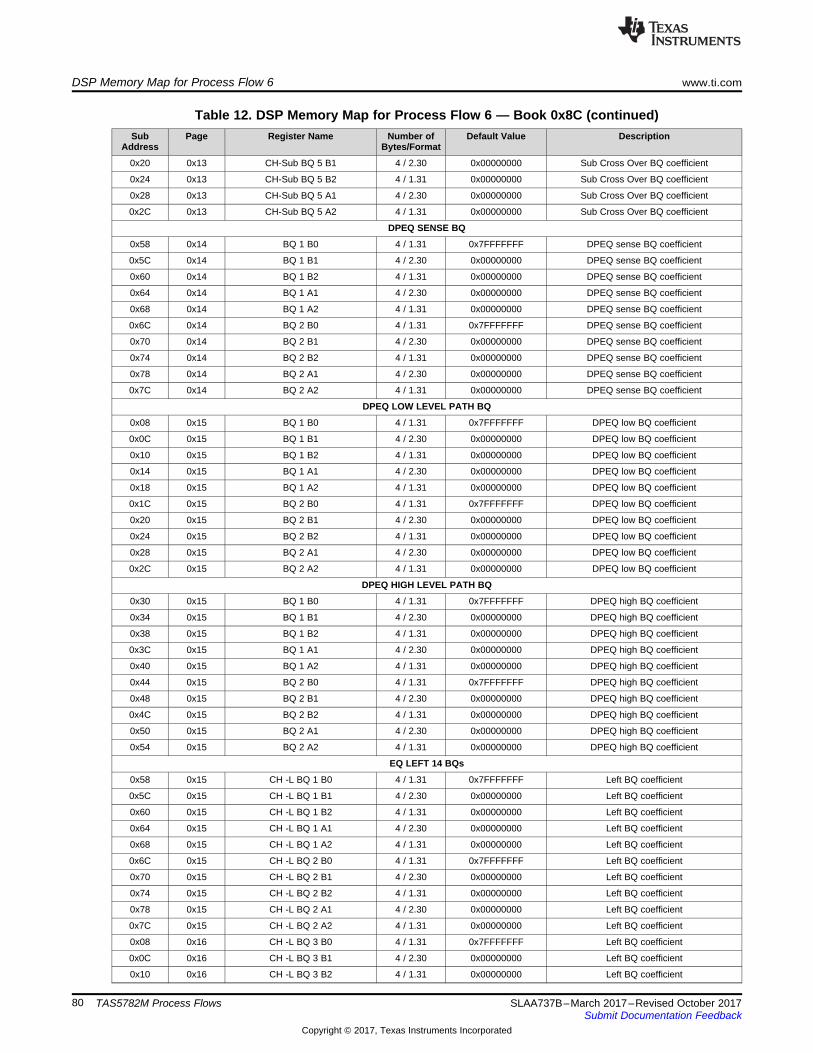
DSP Memory Map for Process Flow 6 www.ti.com
80 SLAA737B–March 2017–Revised October 2017Submit Documentation Feedback
Copyright © 2017, Texas Instruments Incorporated
TAS5782M Process Flows
Table 12. DSP Memory Map for Process Flow 6 — Book 0x8C (continued)Sub
AddressPage Register Name Number of
Bytes/FormatDefault Value Description
0x20 0x13 CH-Sub BQ 5 B1 4 / 2.30 0x00000000 Sub Cross Over BQ coefficient
0x24 0x13 CH-Sub BQ 5 B2 4 / 1.31 0x00000000 Sub Cross Over BQ coefficient
0x28 0x13 CH-Sub BQ 5 A1 4 / 2.30 0x00000000 Sub Cross Over BQ coefficient
0x2C 0x13 CH-Sub BQ 5 A2 4 / 1.31 0x00000000 Sub Cross Over BQ coefficient
DPEQ SENSE BQ
0x58 0x14 BQ 1 B0 4 / 1.31 0x7FFFFFFF DPEQ sense BQ coefficient
0x5C 0x14 BQ 1 B1 4 / 2.30 0x00000000 DPEQ sense BQ coefficient
0x60 0x14 BQ 1 B2 4 / 1.31 0x00000000 DPEQ sense BQ coefficient
0x64 0x14 BQ 1 A1 4 / 2.30 0x00000000 DPEQ sense BQ coefficient
0x68 0x14 BQ 1 A2 4 / 1.31 0x00000000 DPEQ sense BQ coefficient
0x6C 0x14 BQ 2 B0 4 / 1.31 0x7FFFFFFF DPEQ sense BQ coefficient
0x70 0x14 BQ 2 B1 4 / 2.30 0x00000000 DPEQ sense BQ coefficient
0x74 0x14 BQ 2 B2 4 / 1.31 0x00000000 DPEQ sense BQ coefficient
0x78 0x14 BQ 2 A1 4 / 2.30 0x00000000 DPEQ sense BQ coefficient
0x7C 0x14 BQ 2 A2 4 / 1.31 0x00000000 DPEQ sense BQ coefficient
DPEQ LOW LEVEL PATH BQ
0x08 0x15 BQ 1 B0 4 / 1.31 0x7FFFFFFF DPEQ low BQ coefficient
0x0C 0x15 BQ 1 B1 4 / 2.30 0x00000000 DPEQ low BQ coefficient
0x10 0x15 BQ 1 B2 4 / 1.31 0x00000000 DPEQ low BQ coefficient
0x14 0x15 BQ 1 A1 4 / 2.30 0x00000000 DPEQ low BQ coefficient
0x18 0x15 BQ 1 A2 4 / 1.31 0x00000000 DPEQ low BQ coefficient
0x1C 0x15 BQ 2 B0 4 / 1.31 0x7FFFFFFF DPEQ low BQ coefficient
0x20 0x15 BQ 2 B1 4 / 2.30 0x00000000 DPEQ low BQ coefficient
0x24 0x15 BQ 2 B2 4 / 1.31 0x00000000 DPEQ low BQ coefficient
0x28 0x15 BQ 2 A1 4 / 2.30 0x00000000 DPEQ low BQ coefficient
0x2C 0x15 BQ 2 A2 4 / 1.31 0x00000000 DPEQ low BQ coefficient
DPEQ HIGH LEVEL PATH BQ
0x30 0x15 BQ 1 B0 4 / 1.31 0x7FFFFFFF DPEQ high BQ coefficient
0x34 0x15 BQ 1 B1 4 / 2.30 0x00000000 DPEQ high BQ coefficient
0x38 0x15 BQ 1 B2 4 / 1.31 0x00000000 DPEQ high BQ coefficient
0x3C 0x15 BQ 1 A1 4 / 2.30 0x00000000 DPEQ high BQ coefficient
0x40 0x15 BQ 1 A2 4 / 1.31 0x00000000 DPEQ high BQ coefficient
0x44 0x15 BQ 2 B0 4 / 1.31 0x7FFFFFFF DPEQ high BQ coefficient
0x48 0x15 BQ 2 B1 4 / 2.30 0x00000000 DPEQ high BQ coefficient
0x4C 0x15 BQ 2 B2 4 / 1.31 0x00000000 DPEQ high BQ coefficient
0x50 0x15 BQ 2 A1 4 / 2.30 0x00000000 DPEQ high BQ coefficient
0x54 0x15 BQ 2 A2 4 / 1.31 0x00000000 DPEQ high BQ coefficient
EQ LEFT 14 BQs
0x58 0x15 CH -L BQ 1 B0 4 / 1.31 0x7FFFFFFF Left BQ coefficient
0x5C 0x15 CH -L BQ 1 B1 4 / 2.30 0x00000000 Left BQ coefficient
0x60 0x15 CH -L BQ 1 B2 4 / 1.31 0x00000000 Left BQ coefficient
0x64 0x15 CH -L BQ 1 A1 4 / 2.30 0x00000000 Left BQ coefficient
0x68 0x15 CH -L BQ 1 A2 4 / 1.31 0x00000000 Left BQ coefficient
0x6C 0x15 CH -L BQ 2 B0 4 / 1.31 0x7FFFFFFF Left BQ coefficient
0x70 0x15 CH -L BQ 2 B1 4 / 2.30 0x00000000 Left BQ coefficient
0x74 0x15 CH -L BQ 2 B2 4 / 1.31 0x00000000 Left BQ coefficient
0x78 0x15 CH -L BQ 2 A1 4 / 2.30 0x00000000 Left BQ coefficient
0x7C 0x15 CH -L BQ 2 A2 4 / 1.31 0x00000000 Left BQ coefficient
0x08 0x16 CH -L BQ 3 B0 4 / 1.31 0x7FFFFFFF Left BQ coefficient
0x0C 0x16 CH -L BQ 3 B1 4 / 2.30 0x00000000 Left BQ coefficient
0x10 0x16 CH -L BQ 3 B2 4 / 1.31 0x00000000 Left BQ coefficient
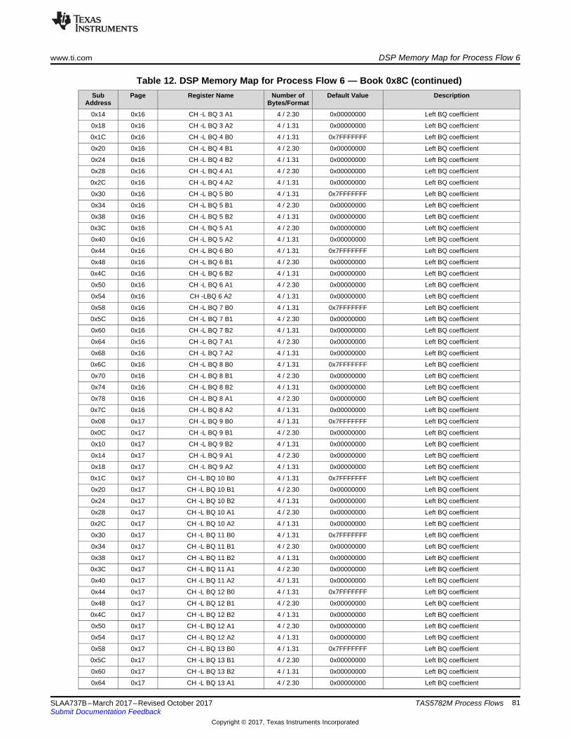
www.ti.com DSP Memory Map for Process Flow 6
81SLAA737B–March 2017–Revised October 2017Submit Documentation Feedback
Copyright © 2017, Texas Instruments Incorporated
TAS5782M Process Flows
Table 12. DSP Memory Map for Process Flow 6 — Book 0x8C (continued)Sub
AddressPage Register Name Number of
Bytes/FormatDefault Value Description
0x14 0x16 CH -L BQ 3 A1 4 / 2.30 0x00000000 Left BQ coefficient
0x18 0x16 CH -L BQ 3 A2 4 / 1.31 0x00000000 Left BQ coefficient
0x1C 0x16 CH -L BQ 4 B0 4 / 1.31 0x7FFFFFFF Left BQ coefficient
0x20 0x16 CH -L BQ 4 B1 4 / 2.30 0x00000000 Left BQ coefficient
0x24 0x16 CH -L BQ 4 B2 4 / 1.31 0x00000000 Left BQ coefficient
0x28 0x16 CH -L BQ 4 A1 4 / 2.30 0x00000000 Left BQ coefficient
0x2C 0x16 CH -L BQ 4 A2 4 / 1.31 0x00000000 Left BQ coefficient
0x30 0x16 CH -L BQ 5 B0 4 / 1.31 0x7FFFFFFF Left BQ coefficient
0x34 0x16 CH -L BQ 5 B1 4 / 2.30 0x00000000 Left BQ coefficient
0x38 0x16 CH -L BQ 5 B2 4 / 1.31 0x00000000 Left BQ coefficient
0x3C 0x16 CH -L BQ 5 A1 4 / 2.30 0x00000000 Left BQ coefficient
0x40 0x16 CH -L BQ 5 A2 4 / 1.31 0x00000000 Left BQ coefficient
0x44 0x16 CH -L BQ 6 B0 4 / 1.31 0x7FFFFFFF Left BQ coefficient
0x48 0x16 CH -L BQ 6 B1 4 / 2.30 0x00000000 Left BQ coefficient
0x4C 0x16 CH -L BQ 6 B2 4 / 1.31 0x00000000 Left BQ coefficient
0x50 0x16 CH -L BQ 6 A1 4 / 2.30 0x00000000 Left BQ coefficient
0x54 0x16 CH -LBQ 6 A2 4 / 1.31 0x00000000 Left BQ coefficient
0x58 0x16 CH -L BQ 7 B0 4 / 1.31 0x7FFFFFFF Left BQ coefficient
0x5C 0x16 CH -L BQ 7 B1 4 / 2.30 0x00000000 Left BQ coefficient
0x60 0x16 CH -L BQ 7 B2 4 / 1.31 0x00000000 Left BQ coefficient
0x64 0x16 CH -L BQ 7 A1 4 / 2.30 0x00000000 Left BQ coefficient
0x68 0x16 CH -L BQ 7 A2 4 / 1.31 0x00000000 Left BQ coefficient
0x6C 0x16 CH -L BQ 8 B0 4 / 1.31 0x7FFFFFFF Left BQ coefficient
0x70 0x16 CH -L BQ 8 B1 4 / 2.30 0x00000000 Left BQ coefficient
0x74 0x16 CH -L BQ 8 B2 4 / 1.31 0x00000000 Left BQ coefficient
0x78 0x16 CH -L BQ 8 A1 4 / 2.30 0x00000000 Left BQ coefficient
0x7C 0x16 CH -L BQ 8 A2 4 / 1.31 0x00000000 Left BQ coefficient
0x08 0x17 CH -L BQ 9 B0 4 / 1.31 0x7FFFFFFF Left BQ coefficient
0x0C 0x17 CH -L BQ 9 B1 4 / 2.30 0x00000000 Left BQ coefficient
0x10 0x17 CH -L BQ 9 B2 4 / 1.31 0x00000000 Left BQ coefficient
0x14 0x17 CH -L BQ 9 A1 4 / 2.30 0x00000000 Left BQ coefficient
0x18 0x17 CH -L BQ 9 A2 4 / 1.31 0x00000000 Left BQ coefficient
0x1C 0x17 CH -L BQ 10 B0 4 / 1.31 0x7FFFFFFF Left BQ coefficient
0x20 0x17 CH -L BQ 10 B1 4 / 2.30 0x00000000 Left BQ coefficient
0x24 0x17 CH -L BQ 10 B2 4 / 1.31 0x00000000 Left BQ coefficient
0x28 0x17 CH -L BQ 10 A1 4 / 2.30 0x00000000 Left BQ coefficient
0x2C 0x17 CH -L BQ 10 A2 4 / 1.31 0x00000000 Left BQ coefficient
0x30 0x17 CH -L BQ 11 B0 4 / 1.31 0x7FFFFFFF Left BQ coefficient
0x34 0x17 CH -L BQ 11 B1 4 / 2.30 0x00000000 Left BQ coefficient
0x38 0x17 CH -L BQ 11 B2 4 / 1.31 0x00000000 Left BQ coefficient
0x3C 0x17 CH -L BQ 11 A1 4 / 2.30 0x00000000 Left BQ coefficient
0x40 0x17 CH -L BQ 11 A2 4 / 1.31 0x00000000 Left BQ coefficient
0x44 0x17 CH -L BQ 12 B0 4 / 1.31 0x7FFFFFFF Left BQ coefficient
0x48 0x17 CH -L BQ 12 B1 4 / 2.30 0x00000000 Left BQ coefficient
0x4C 0x17 CH -L BQ 12 B2 4 / 1.31 0x00000000 Left BQ coefficient
0x50 0x17 CH -L BQ 12 A1 4 / 2.30 0x00000000 Left BQ coefficient
0x54 0x17 CH -L BQ 12 A2 4 / 1.31 0x00000000 Left BQ coefficient
0x58 0x17 CH -L BQ 13 B0 4 / 1.31 0x7FFFFFFF Left BQ coefficient
0x5C 0x17 CH -L BQ 13 B1 4 / 2.30 0x00000000 Left BQ coefficient
0x60 0x17 CH -L BQ 13 B2 4 / 1.31 0x00000000 Left BQ coefficient
0x64 0x17 CH -L BQ 13 A1 4 / 2.30 0x00000000 Left BQ coefficient

DSP Memory Map for Process Flow 6 www.ti.com
82 SLAA737B–March 2017–Revised October 2017Submit Documentation Feedback
Copyright © 2017, Texas Instruments Incorporated
TAS5782M Process Flows
Table 12. DSP Memory Map for Process Flow 6 — Book 0x8C (continued)Sub
AddressPage Register Name Number of
Bytes/FormatDefault Value Description
0x68 0x17 CH -L BQ 13 A2 4 / 1.31 0x00000000 Left BQ coefficient
0x6C 0x17 CH -L BQ 14 B0 4 / 1.31 0x7FFFFFFF Left BQ coefficient
0x70 0x17 CH -L BQ 14 B1 4 / 2.30 0x00000000 Left BQ coefficient
0x74 0x17 CH -L BQ 14 B2 4 / 1.31 0x00000000 Left BQ coefficient
0x78 0x17 CH -L BQ 14 A1 4 / 2.30 0x00000000 Left BQ coefficient
0x7C 0x17 CH -L BQ 14 A2 4 / 1.31 0x00000000 Left BQ coefficient
LEFT INTGAIN BQ
0x08 0x18 CH -L BQ 15 B0 4 / 5.27 0x08000000 Left gain scale BQ coefficient
0x0C 0x18 CH -L BQ 15 B1 4 / 6.26 0x00000000 Left gain scale BQ coefficient
0x10 0x18 CH -L BQ 15 B2 4 / 5.27 0x00000000 Left gain scale BQ coefficient
0x14 0x18 CH -L BQ 15 A1 4 / 2.30 0x00000000 Left gain scale BQ coefficient
0x18 0x18 CH -L BQ 15 A2 4 / 1.31 0x00000000 Left gain scale BQ coefficient
EQ RIGHT 14 BQs
0x1C 0x18 CH -R BQ 1 B0 4 / 1.31 0x7FFFFFFF Right BQ coefficient
0x20 0x18 CH -R BQ 1 B1 4 / 2.30 0x00000000 Right BQ coefficient
0x24 0x18 CH -R BQ 1 B2 4 / 1.31 0x00000000 Right BQ coefficient
0x28 0x18 CH -R BQ 1 A1 4 / 2.30 0x00000000 Right BQ coefficient
0x2C 0x18 CH -R BQ 1 A2 4 / 1.31 0x00000000 Right BQ coefficient
0x30 0x18 CH -R BQ 2 B0 4 / 1.31 0x7FFFFFFF Right BQ coefficient
0x34 0x18 CH -R BQ 2 B1 4 / 2.30 0x00000000 Right BQ coefficient
0x38 0x18 CH -R BQ 2 B2 4 / 1.31 0x00000000 Right BQ coefficient
0x3C 0x18 CH -R BQ 2 A1 4 / 2.30 0x00000000 Right BQ coefficient
0x40 0x18 CH -R BQ 2 A2 4 / 1.31 0x00000000 Right BQ coefficient
0x44 0x18 CH -R BQ 3 B0 4 / 1.31 0x7FFFFFFF Right BQ coefficient
0x48 0x18 CH -R BQ 3 B1 4 / 2.30 0x00000000 Right BQ coefficient
0x4C 0x18 CH -R BQ 3 B2 4 / 1.31 0x00000000 Right BQ coefficient
0x50 0x18 CH -R BQ 3 A1 4 / 2.30 0x00000000 Right BQ coefficient
0x54 0x18 CH -R BQ 3 A2 4 / 1.31 0x00000000 Right BQ coefficient
0x58 0x18 CH -R BQ 4 B0 4 / 1.31 0x7FFFFFFF Right BQ coefficient
0x5C 0x18 CH -R BQ 4 B1 4 / 2.30 0x00000000 Right BQ coefficient
0x60 0x18 CH -R BQ 4 B2 4 / 1.31 0x00000000 Right BQ coefficient
0x64 0x18 CH -R BQ 4 A1 4 / 2.30 0x00000000 Right BQ coefficient
0x68 0x18 CH -R BQ 4 A2 4 / 1.31 0x00000000 Right BQ coefficient
0x6C 0x18 CH -R BQ 5 B0 4 / 1.31 0x7FFFFFFF Right BQ coefficient
0x70 0x18 CH -R BQ 5 B1 4 / 2.30 0x00000000 Right BQ coefficient
0x74 0x18 CH -R BQ 5 B2 4 / 1.31 0x00000000 Right BQ coefficient
0x78 0x18 CH -R BQ 5 A1 4 / 2.30 0x00000000 Right BQ coefficient
0x7C 0x18 CH -R BQ 5 A2 4 / 1.31 0x00000000 Right BQ coefficient
0x08 0x19 CH -R BQ 6 B0 4 / 1.31 0x7FFFFFFF Right BQ coefficient
0x0C 0x19 CH -R BQ 6 B1 4 / 2.30 0x00000000 Right BQ coefficient
0x10 0x19 CH -R BQ 6 B2 4 / 1.31 0x00000000 Right BQ coefficient
0x14 0x19 CH -R BQ 6 A1 4 / 2.30 0x00000000 Right BQ coefficient
0x18 0x19 CH -R BQ 6 A2 4 / 1.31 0x00000000 Right BQ coefficient
0x1C 0x19 CH -R BQ 7 B0 4 / 1.31 0x7FFFFFFF Right BQ coefficient
0x20 0x19 CH -R BQ 7 B1 4 / 2.30 0x00000000 Right BQ coefficient
0x24 0x19 CH -R BQ 7 B2 4 / 1.31 0x00000000 Right BQ coefficient
0x28 0x19 CH -R BQ 7 A1 4 / 2.30 0x00000000 Right BQ coefficient
0x2C 0x19 CH -R BQ 7 A2 4 / 1.31 0x00000000 Right BQ coefficient
0x30 0x19 CH -R BQ 8 B0 4 / 1.31 0x7FFFFFFF Right BQ coefficient
0x34 0x19 CH -R BQ 8 B1 4 / 2.30 0x00000000 Right BQ coefficient
0x38 0x19 CH -R BQ 8 B2 4 / 1.31 0x00000000 Right BQ coefficient

www.ti.com DSP Memory Map for Process Flow 6
83SLAA737B–March 2017–Revised October 2017Submit Documentation Feedback
Copyright © 2017, Texas Instruments Incorporated
TAS5782M Process Flows
Table 12. DSP Memory Map for Process Flow 6 — Book 0x8C (continued)Sub
AddressPage Register Name Number of
Bytes/FormatDefault Value Description
0x3C 0x19 CH -R BQ 8 A1 4 / 2.30 0x00000000 Right BQ coefficient
0x40 0x19 CH -R BQ 8 A2 4 / 1.31 0x00000000 Right BQ coefficient
0x44 0x19 CH -R BQ 9 B0 4 / 1.31 0x7FFFFFFF Right BQ coefficient
0x48 0x19 CH -R BQ 9 B1 4 / 2.30 0x00000000 Right BQ coefficient
0x4C 0x19 CH -R BQ 9 B2 4 / 1.31 0x00000000 Right BQ coefficient
0x50 0x19 CH -R BQ 9 A1 4 / 2.30 0x00000000 Right BQ coefficient
0x54 0x19 CH -R BQ 9 A2 4 / 1.31 0x00000000 Right BQ coefficient
0x58 0x19 CH -R BQ 10 B0 4 / 1.31 0x7FFFFFFF Right BQ coefficient
0x5C 0x19 CH -R BQ 10 B1 4 / 2.30 0x00000000 Right BQ coefficient
0x60 0x19 CH -R BQ 10 B2 4 / 1.31 0x00000000 Right BQ coefficient
0x64 0x19 CH -R BQ 10 A1 4 / 2.30 0x00000000 Right BQ coefficient
0x68 0x19 CH -R BQ 10 A2 4 / 1.31 0x00000000 Right BQ coefficient
0x6C 0x19 CH -R BQ 11 B0 4 / 1.31 0x7FFFFFFF Right BQ coefficient
0x70 0x19 CH -R BQ 11 B1 4 / 2.30 0x00000000 Right BQ coefficient
0x74 0x19 CH -R BQ 11 B2 4 / 1.31 0x00000000 Right BQ coefficient
0x78 0x19 CH -R BQ 11 A1 4 / 2.30 0x00000000 Right BQ coefficient
0x7C 0x19 CH -R BQ 11 A2 4 / 1.31 0x00000000 Right BQ coefficient
0x08 0x1A CH -R BQ 12 B0 4 / 1.31 0x7FFFFFFF Right BQ coefficient
0x0C 0x1A CH -R BQ 12 B1 4 / 2.30 0x00000000 Right BQ coefficient
0x10 0x1A CH -R BQ 12 B2 4 / 1.31 0x00000000 Right BQ coefficient
0x14 0x1A CH -R BQ 12 A1 4 / 2.30 0x00000000 Right BQ coefficient
0x18 0x1A CH -R BQ 12 A2 4 / 1.31 0x00000000 Right BQ coefficient
0x1C 0x1A CH -R BQ 13 B0 4 / 1.31 0x7FFFFFFF Right BQ coefficient
0x20 0x1A CH -R BQ 13 B1 4 / 2.30 0x00000000 Right BQ coefficient
0x24 0x1A CH -R BQ 13 B2 4 / 1.31 0x00000000 Right BQ coefficient
0x28 0x1A CH -R BQ 13 A1 4 / 2.30 0x00000000 Right BQ coefficient
0x2C 0x1A CH -R BQ 13 A2 4 / 1.31 0x00000000 Right BQ coefficient
0x30 0x1A CH -R BQ 14 B0 4 / 1.31 0x7FFFFFFF Right BQ coefficient
0x34 0x1A CH -R BQ 14 B1 4 / 2.30 0x00000000 Right BQ coefficient
0x38 0x1A CH -R BQ 14 B2 4 / 1.31 0x00000000 Right BQ coefficient
0x3C 0x1A CH -R BQ 14 A1 4 / 2.30 0x00000000 Right BQ coefficient
0x40 0x1A CH -R BQ 14 A2 4 / 1.31 0x00000000 Right BQ coefficient
RIGHT INTGAIN BQ
0x44 0x1A CH -R BQ 15 B0 4 / 5.27 0x08000000 Right gain scale BQ coefficient
0x48 0x1A CH -R BQ 15 B1 4 / 6.26 0x00000000 Right gain scale BQ coefficient
0x4C 0x1A CH -R BQ 15 B2 4 / 5.27 0x00000000 Right gain scale BQ coefficient
0x50 0x1A CH -R BQ 15 A1 4 / 2.30 0x00000000 Right gain scale BQ coefficient
0x54 0x1A CH -R BQ 15 A2 4 / 1.31 0x00000000 Right gain scale BQ coefficient
VOLUME ALPHA FILTER
0x58 0x1A Softening Filter Alpha 4 / 1.31 0x00A7264A Volume time constant
PHASE OPTIMIZER
0x60 0x1A Delay Left 4 / 32.0 0x00000000 Left Channel Phase Optimizer
0x64 0x1A Delay Right 4 / 32.0 0x00000000 Right Channel Phase Optimizer
0x68 0x1A Delay Sub 4 / 32.0 0x00000000 Sub Channel Phase Optimizer
SPATIALIZER BQs
0x6C 0x1C BQ 1 B0 4 / 1.31 0x7FFFFFFF Spatializer BQ coefficient
0x70 0x1C BQ 1 B1 4 / 2.30 0x00000000 Spatializer BQ coefficient
0x74 0x1C BQ 1 B2 4 / 1.31 0x00000000 Spatializer BQ coefficient
0x78 0x1C BQ 1 A1 4 / 2.30 0x00000000 Spatializer BQ coefficient
0x7C 0x1C BQ 1 A2 4 / 1.31 0x00000000 Spatializer BQ coefficient
0x08 0x1D BQ 2 B0 4 / 1.31 0x7FFFFFFF Spatializer BQ coefficient

DSP Memory Map for Process Flow 6 www.ti.com
84 SLAA737B–March 2017–Revised October 2017Submit Documentation Feedback
Copyright © 2017, Texas Instruments Incorporated
TAS5782M Process Flows
Table 12. DSP Memory Map for Process Flow 6 — Book 0x8C (continued)Sub
AddressPage Register Name Number of
Bytes/FormatDefault Value Description
0x0C 0x1D BQ 2 B1 4 / 2.30 0x00000000 Spatializer BQ coefficient
0x10 0x1D BQ 2 B2 4 / 1.31 0x00000000 Spatializer BQ coefficient
0x14 0x1D BQ 2 A1 4 / 2.30 0x00000000 Spatializer BQ coefficient
0x18 0x1D BQ 2 A2 4 / 1.31 0x00000000 Spatializer BQ coefficient
DPEQ CONTROL
0x1C 0x1D Alpha 4 / 1.31 0x02DEAD00 DPEQ Sense Energy Time constant
0x20 0x1D Gain 4 / 1.31 0x74013901 DPEQ Threshold Gain
0x24 0x1D Offset 4 / 1.31 0x0020C49B DPEQ Threshold Offset
SUB CHANNEL CONTROL
0x28 0x1D No Sub 4 / 32.0 0x00000000 Sub Channel Flag
THD CLIPPER
0x2C 0x1D CH-LR THD Boost 4 / 9.23 0x00800000 THD LR Channel prescale coefficient
0x30 0x1D CH-Sub THD Boost 4 / 9.23 0x00800000 THD Sub Channel prescale coefficient
0x34 0x1D CH-L Fine Volume 4 / 2.30 0x3FFFFFFF THD L Channel postscale coefficient
0x38 0x1D CH-R Fine Volume 4 / 2.30 0x3FFFFFFF THD R Channel postscale coefficient
0x3C 0x1D CH-Sub Fine Volume 4 / 2.30 0x3FFFFFFF THD Sub Channel postscale coefficient
GANG EQ
0x58 0x1D Gang LR EQ 4 / 32.0 0x00000000 Gang Left and Right EQ flag
INPUT MIXER
0x5C 0x1D Left to Left 4 / 9.23 0x00800000 Left Channel Mixer Left Input Gain
0x60 0x1D Right to Left 4 / 9.23 0x00000000 Left Channel Mixer Right Input Gain
0x64 0x1D Left to Right 4 / 9.23 0x00000000 Right Channel Mixer Left Input Gain
0x68 0x1D Right to Right 4 / 9.23 0x00800000 Right Channel Mixer Right Input Gain
MIX/GAIN ADJUST
0x6C 0x1D Left to Sub 4 / 9.23 0x00000000 Sub Channel Mixer Left Input Gain
0x70 0x1D Right to Sub 4 / 9.23 0x00000000 Sub Channel Mixer Right Input Gain
0x74 0x1D Sub Mix ScratchL 4 / 9.23 0x00800000 Sub Channel Mixer ScratchL Input Gain
0x78 0x1D Sub Mix ScratchR 4 / 9.23 0x00000000 Sub Channel Mixer ScratchR Input Gain
0x7C 0x1D Bass Mono Left 4 / 9.23 0x00800000 Mono Left Input Gain
0x08 0x1E Bass Mono Right 4 / 9.23 0x00800000 Mono Right Input Gain
0x0C 0x1E Bass Mono Sub 4 / 9.23 0x00000000 Mono Sub Input Gain
SPATIALIZER LEVEL
0x10 0x1E Spatializer Level 4 / 9.23 0x00000000 Spatializer Level coefficient
OUTPUT CROSS BAR
0x14 0x1E Digital Left from Left 4 / 9.23 0x00800000 I2S Left output gain from left
0x18 0x1E Digital Left from Right 4 / 9.23 0x00000000 I2S Left output gain from Right
0x1C 0x1E Digital Left from Sub 4 / 9.23 0x00000000 I2S Left output gain from Sub
0x20 0x1E Digital Right from Left 4 / 9.23 0x00000000 I2S Right output gain from left
0x24 0x1E Digital Right from Right 4 / 9.23 0x00800000 I2S Right output gain from Right
0x28 0x1E Digital Right from Sub 4 / 9.23 0x00000000 I2S Right output gain from Sub
0x2C 0x1E Analog Left from Left 4 / 9.23 0x00800000 Analog Left output gain from left
0x30 0x1E Analog Left from Right 4 / 9.23 0x00000000 Analog Left output gain from Right
0x34 0x1E Analog Left from Sub 4 / 9.23 0x00000000 Analog Left output gain from Sub
0x38 0x1E Analog Right from Left 4 / 9.23 0x00000000 Analog Right output gain from left
0x3C 0x1E Analog Right from Right 4 / 9.23 0x00800000 Analog Right output gain from Right
0x40 0x1E Analog Right from Sub 4 / 9.23 0x00000000 Analog Right output gain from Sub
VOLUME CONTROL
0x44 0x1E CH-L Volume 4 / 9.23 0x00800000 Left Channel volume coefficient
0x48 0x1E CH-R Volume 4 / 9.23 0x00800000 Right Channel volume coefficient
0x4C 0x1E CH-Sub Volume 4 / 9.23 0x00800000 Sub Channel volume coefficient

www.ti.com DSP Memory Map for Process Flow 6
85SLAA737B–March 2017–Revised October 2017Submit Documentation Feedback
Copyright © 2017, Texas Instruments Incorporated
TAS5782M Process Flows
Table 12. DSP Memory Map for Process Flow 6 — Book 0x8C (continued)Sub
AddressPage Register Name Number of
Bytes/FormatDefault Value Description
DPEQ GAIN SCALE
0x50 0x1E DPEQ Sense Scale 4 / 2.30 0x40000000 DPEQ Sense Input Gain
0x54 0x1E DPEQ Low Scale 4 / 6.26 0x04000000 DPEQ Low Input Gain
0x58 0x1E DPEQ High Scale 4 / 6.26 0x04000000 DPEQ High Input Gain
THERMAL PROTECT
0x5C 0x1E Thermal 4 / - 0x0020C49C Generated by GUI
0x60 0x1E Thermal 4 / - 0x0020C49C Generated by GUI
0x64 0x1E Thermal 4 / - 0x0020C49C Generated by GUI
0x68 0x1E Thermal 4 / - 0x0020C49C Generated by GUI
RAM
THERMAL PROTECT
0x34 0x1F Thermal 4 / - 0x00A7264A Generated by GUI
0x38 0x1F Thermal 4 / - 0x00A7264A Generated by GUI
MORPHING CONTROL
0x3C 0x1F Morphing Energy 4 / 1.31 0x7FFFFFFF Morphing Energy Time constant
0x40 0x1F Morphing Attack 4 / 1.31 0x7FFFFFFF Morphing Attack Time constant
0x44 0x1F Morphing Decay 4 / 1.31 0x7FFFFFFF Morphing Decay Time constant
0x48 0x1F Morphing K0_1 4 / 9.23 0x00000000 Morphing Region 1 Slope (comp/Exp)
0x4C 0x1F Morphing K1_1 4 / 9.23 0x00000000 Morphing Region 2 Slope (comp/Exp)
0x50 0x1F Morphing K2_1 4 / 9.23 0x00000000 Morphing Region 3 Slope (comp/Exp)
0x54 0x1F Morphing T1_1 4 / 9.23 0xE7000000 Morphing Threshold 1
0x58 0x1F Morphing T2_1 4 / 9.23 0xFE800000 Morphing Threshold 2
0x5C 0x1F Morphing off1_1 4 / 9.23 0x00000000 Morphing Offset 1
0x60 0x1F Morphing off2_1 4 / 9.23 0x00000000 Morphing Offset 2
EXCURSION
0x64 0x1F Excursion 4 / - 0x024D9999 Generated by GUI
0x68 0x1F Excursion 4 / - 0xFDB26667 Generated by GUI
0x6C 0x1F Excursion 4 / - 0x00800000 Generated by GUI
0x70 0x1F Excursion 4 / - 0x00000000 Generated by GUI
0x74 0x1F Excursion 4 / - 0x00000000 Generated by GUI
0x78 0x1F Excursion 4 / - 0x00000000 Generated by GUI
0x7C 0x1F Excursion 4 / - 0x00000000 Generated by GUI
0x08 0x20 Excursion 4 / - 0x00000000 Generated by GUI
0x0C 0x20 Excursion 4 / - 0x00000000 Generated by GUI
0x10 0x20 Excursion 4 / - 0x00000000 Generated by GUI
0x14 0x20 Excursion 4 / - 0x00000000 Generated by GUI
0x18 0x20 Excursion 4 / - 0x00000000 Generated by GUI
0x1C 0x20 Excursion 4 / - 0x00000000 Generated by GUI
0x20 0x20 Excursion 4 / - 0x00000000 Generated by GUI
0x24 0x20 Excursion 4 / - 0x00000000 Generated by GUI
0x28 0x20 Excursion 4 / - 0x00000000 Generated by GUI
0x2C 0x20 Excursion 4 / - 0x00000000 Generated by GUI
0x30 0x20 Excursion 4 / - 0x00000000 Generated by GUI
0x34 0x20 Excursion 4 / - 0x00000000 Generated by GUI
0x38 0x20 Excursion 4 / - 0x00000000 Generated by GUI
0x3C 0x20 Excursion 4 / - 0x00000000 Generated by GUI
0x40 0x20 Excursion 4 / - 0x00000000 Generated by GUI
0x44 0x20 Excursion 4 / - 0x00000000 Generated by GUI
0x48 0x20 Excursion 4 / - 0x00000000 Generated by GUI
0x4C 0x20 Excursion 4 / - 0x00000000 Generated by GUI
0x50 0x20 Excursion 4 / - 0x00000000 Generated by GUI

DSP Memory Map for Process Flow 6 www.ti.com
86 SLAA737B–March 2017–Revised October 2017Submit Documentation Feedback
Copyright © 2017, Texas Instruments Incorporated
TAS5782M Process Flows
Table 12. DSP Memory Map for Process Flow 6 — Book 0x8C (continued)Sub
AddressPage Register Name Number of
Bytes/FormatDefault Value Description
0x54 0x20 Excursion 4 / - 0x00000000 Generated by GUI
0x58 0x20 Excursion 4 / - 0x00000000 Generated by GUI
0x5C 0x20 Excursion 4 / - 0x00000000 Generated by GUI
0x60 0x20 Excursion 4 / - 0x00000000 Generated by GUI
0x64 0x20 Excursion 4 / - 0x00000000 Generated by GUI
0x68 0x20 Excursion 4 / - 0x00000000 Generated by GUI
0x6C 0x20 Excursion 4 / - 0x00000000 Generated by GUI
0x70 0x20 Excursion 4 / - 0x7FFFFFFF Generated by GUI
0x74 0x20 Excursion 4 / - 0x00000000 Generated by GUI
0x78 0x20 Excursion 4 / - 0x00000000 Generated by GUI
0x7C 0x20 Excursion 4 / - 0x00000000 Generated by GUI
0x08 0x21 Excursion 4 / - 0x00000000 Generated by GUI
0x0C 0x21 Excursion 4 / - 0x7FFFFFFF Generated by GUI
0x10 0x21 Excursion 4 / - 0x00000000 Generated by GUI
0x14 0x21 Excursion 4 / - 0x00000000 Generated by GUI
0x18 0x21 Excursion 4 / - 0x00000000 Generated by GUI
0x1C 0x21 Excursion 4 / - 0x00000000 Generated by GUI
MORPHING BQs
0x20 0x21 BQ 1 B0 4 / 1.31 0x7FFFFFFF Morphing BQ coefficient
0x24 0x21 BQ 1 B1 4 / 2.30 0x00000000 Morphing BQ coefficient
0x28 0x21 BQ 1 B2 4 / 1.31 0x00000000 Morphing BQ coefficient
0x2C 0x21 BQ 1 A1 4 / 2.30 0x00000000 Morphing BQ coefficient
0x30 0x21 BQ 1 A2 4 / 1.31 0x00000000 Morphing BQ coefficient
0x34 0x21 BQ 2 B0 4 / 1.31 0x7FFFFFFF Morphing BQ coefficient
0x38 0x21 BQ 2 B1 4 / 2.30 0x00000000 Morphing BQ coefficient
0x3C 0x21 BQ 2 B2 4 / 1.31 0x00000000 Morphing BQ coefficient
0x40 0x21 BQ 2 A1 4 / 2.30 0x00000000 Morphing BQ coefficient
0x44 0x21 BQ 2 A2 4 / 1.31 0x00000000 Morphing BQ coefficient
0x48 0x21 CH-Sub Gain scale 4 / 9.23 0x00800000 Sub Channel Morphing Gain
THERMAL PROTECT TRESHOLD
0x4C 0x21 Thermal 4 / - 0x7FFFFFFF Generated by GUI
0x50 0x21 Thermal 4 / - 0x7FFFFFFF Generated by GUI

AVDD/DVDD
PVDD
RESET
I2S (MCLK, SCLK, LRCK)
I2C SAI Configuration Mute Enable DSP DSP Coefficients Unmute
Initialization Normal Operation
Wait for clocks to be stable 103 FS periods (normally 5ms)
0 ns
100 µs
0 ns
100 µs
87SLAA737B–March 2017–Revised October 2017Submit Documentation Feedback
Copyright © 2017, Texas Instruments Incorporated
TAS5782M Process Flows
Appendix BSLAA737B–March 2017–Revised October 2017
Power-Up and Power-Down Sequence
B.1 Power-Up SequenceUse the following list for power-up:1. Hold all digital inputs low and bring up power supplies (it doesn’t matter if AVDD/DVDD or PVDD
comes up first).2. Hold RESET low and initialize digital inputs to their desired states. Wait at least 100 µs, pull RESET
high and then wait at least another 100 µs.3. Configure the SAI (Serial Audio Interface) as required via i2c and then start MCLK, SCLK and LRCLK
(no sequence required).4. Mute the device (write 0x11 to B0-P0-R3) or pulling low SPK_MUTE pin.5. Once clocks are stable, put the device into normal operation mode (write 0x00 to B0-P0-R2), and wait
at least 103 FS periods (normally 5ms).6. Start to program DSP coefficients. If a process flow with SmartAmp processing is used, like Process
Flow 2, Process Flow 4 or Process Flow 6, it is required to download DSP instructions only after DSPhas been reset (write 0x80 to B0-P0-R2).
7. Unmute the device (write 0x00 to B0-P0-R3) or pulling high SPK_MUTE pin.8. The device is now in normal operation.
Figure 36. Power-Up Timing

AVDD/DVDD
PVDD
RESET
I2C Power Down Device
2 µs
2 µs
2 µs2 ms
Power-Down Sequence www.ti.com
88 SLAA737B–March 2017–Revised October 2017Submit Documentation Feedback
Copyright © 2017, Texas Instruments Incorporated
Revision History
B.2 Power-Down SequenceThe following list details the power-down sequence:1. Put the device into power down mode (write 0x01 to B0-P0-R2).2. Wait at least 2 ms and then pull RESET low.3. The clocks can be stopped and the power supplies brought down after RESET has been low for at
least 2 µs.4. The device is now fully shutdown and powered off.
Figure 37. Power-Down Timing
Revision HistoryNOTE: Page numbers for previous revisions may differ from page numbers in the current version.
Changes from A Revision (June 2017) to B Revision .................................................................................................... Page
• Added use cases to Supported Use Cases............................................................................................ 4• Added Process Flows 5–6. .............................................................................................................. 5• Added Process Flow 5 (48 kHz, 2.1 Standard Processing) . ...................................................................... 14• Added Process Flow 6 (48 kHz, 2.1 SmartAmp Processing) . .................................................................... 16• Added DSP Memory Map for Process Flow 5 ....................................................................................... 70• Added DSP Memory Map for Process Flow 6. ...................................................................................... 79
Revision History
Changes from Original (March 2017) to A Revision ....................................................................................................... Page
• Deleted the following sentence, "All BQ coefficients are written in the 1.31 format." in the Equalizer section. ............. 19• Deleted sentence and equation below the Volume Attack and Decay image. .................................................. 21• Deleted SWAP FLAG entry from DSP Memory Map for Process Flow 1 — Book 0x8C table. ............................... 46• Deleted SWAP FLAG entry from DSP Memory Map for Process Flow 2 — Book 0x8C table. ............................... 51• Changed title of the table in the DSP Memory Map for Process Flow 3 section to the current title. ......................... 56• Deleted SWAP FLAG entry from DSP Memory Map for Process Flow 3 — Book 0x8C table. ............................... 56• Changed title of the table in the DSP Memory Map for Process Flow 4 section to the current title. ......................... 63• Deleted SWAP FLAG entry from DSP Memory Map for Process Flow 4— Book 0x8C table. ................................ 63

IMPORTANT NOTICE FOR TI DESIGN INFORMATION AND RESOURCES
Texas Instruments Incorporated (‘TI”) technical, application or other design advice, services or information, including, but not limited to,reference designs and materials relating to evaluation modules, (collectively, “TI Resources”) are intended to assist designers who aredeveloping applications that incorporate TI products; by downloading, accessing or using any particular TI Resource in any way, you(individually or, if you are acting on behalf of a company, your company) agree to use it solely for this purpose and subject to the terms ofthis Notice.TI’s provision of TI Resources does not expand or otherwise alter TI’s applicable published warranties or warranty disclaimers for TIproducts, and no additional obligations or liabilities arise from TI providing such TI Resources. TI reserves the right to make corrections,enhancements, improvements and other changes to its TI Resources.You understand and agree that you remain responsible for using your independent analysis, evaluation and judgment in designing yourapplications and that you have full and exclusive responsibility to assure the safety of your applications and compliance of your applications(and of all TI products used in or for your applications) with all applicable regulations, laws and other applicable requirements. Yourepresent that, with respect to your applications, you have all the necessary expertise to create and implement safeguards that (1)anticipate dangerous consequences of failures, (2) monitor failures and their consequences, and (3) lessen the likelihood of failures thatmight cause harm and take appropriate actions. You agree that prior to using or distributing any applications that include TI products, youwill thoroughly test such applications and the functionality of such TI products as used in such applications. TI has not conducted anytesting other than that specifically described in the published documentation for a particular TI Resource.You are authorized to use, copy and modify any individual TI Resource only in connection with the development of applications that includethe TI product(s) identified in such TI Resource. NO OTHER LICENSE, EXPRESS OR IMPLIED, BY ESTOPPEL OR OTHERWISE TOANY OTHER TI INTELLECTUAL PROPERTY RIGHT, AND NO LICENSE TO ANY TECHNOLOGY OR INTELLECTUAL PROPERTYRIGHT OF TI OR ANY THIRD PARTY IS GRANTED HEREIN, including but not limited to any patent right, copyright, mask work right, orother intellectual property right relating to any combination, machine, or process in which TI products or services are used. Informationregarding or referencing third-party products or services does not constitute a license to use such products or services, or a warranty orendorsement thereof. Use of TI Resources may require a license from a third party under the patents or other intellectual property of thethird party, or a license from TI under the patents or other intellectual property of TI.TI RESOURCES ARE PROVIDED “AS IS” AND WITH ALL FAULTS. TI DISCLAIMS ALL OTHER WARRANTIES ORREPRESENTATIONS, EXPRESS OR IMPLIED, REGARDING TI RESOURCES OR USE THEREOF, INCLUDING BUT NOT LIMITED TOACCURACY OR COMPLETENESS, TITLE, ANY EPIDEMIC FAILURE WARRANTY AND ANY IMPLIED WARRANTIES OFMERCHANTABILITY, FITNESS FOR A PARTICULAR PURPOSE, AND NON-INFRINGEMENT OF ANY THIRD PARTY INTELLECTUALPROPERTY RIGHTS.TI SHALL NOT BE LIABLE FOR AND SHALL NOT DEFEND OR INDEMNIFY YOU AGAINST ANY CLAIM, INCLUDING BUT NOTLIMITED TO ANY INFRINGEMENT CLAIM THAT RELATES TO OR IS BASED ON ANY COMBINATION OF PRODUCTS EVEN IFDESCRIBED IN TI RESOURCES OR OTHERWISE. IN NO EVENT SHALL TI BE LIABLE FOR ANY ACTUAL, DIRECT, SPECIAL,COLLATERAL, INDIRECT, PUNITIVE, INCIDENTAL, CONSEQUENTIAL OR EXEMPLARY DAMAGES IN CONNECTION WITH ORARISING OUT OF TI RESOURCES OR USE THEREOF, AND REGARDLESS OF WHETHER TI HAS BEEN ADVISED OF THEPOSSIBILITY OF SUCH DAMAGES.You agree to fully indemnify TI and its representatives against any damages, costs, losses, and/or liabilities arising out of your non-compliance with the terms and provisions of this Notice.This Notice applies to TI Resources. Additional terms apply to the use and purchase of certain types of materials, TI products and services.These include; without limitation, TI’s standard terms for semiconductor products http://www.ti.com/sc/docs/stdterms.htm), evaluationmodules, and samples (http://www.ti.com/sc/docs/sampterms.htm).
Mailing Address: Texas Instruments, Post Office Box 655303, Dallas, Texas 75265Copyright © 2017, Texas Instruments Incorporated