Targeted Products and Programs for Welding
28
Targeted Products and Programs for Welding Weld Select Series
Transcript of Targeted Products and Programs for Welding

Targeted Products and Programs for WeldingWeld Select Series

www.balluff.com/welding�
Weld Select Series Weld Select is an industry proven group of Balluff products designed for use in the most inhospitable welding environments. Poor sensor selection costs welders in every industry increased downtime, unnecessary maintenance, delayed delivery, and lost profits. Now Balluff presents a complete package of welding solutions that extends sensor life and increases productivity in the harshest welding environments.
This guide contains two sections. The front section is designed to help all plant levels identify existing issues and offer Balluff-developed solutions to address them. The second section offers an extensive list of products developed by Balluff welding experts from valuable customer input. These products have been tested in the harshest welding environments and provide significant process and part quality improvement.
Stop Wasting Sensors and destroying connectors
Change the Paradigm of accepted high volume sensor usage
Reduce Downtime due to sensor failure
Slash Consumption of sensors and connectors
Boost Profitability throughout the plant
www.balluff.com/welding
- New Product News- Welding Application Reports- Industry Articles- Sensor Information- Case Studies
Pre-Engineered Automation System: Fanuc ArcMate Robot with Lincoln Electric Welding Package, featuring the Balluff zone limit system.
Balluff’s Holistic Approach to Weld Cell Process Improvement
n Expert analysis of all problematic sensor “hotspots” on your plant floor
n Timely and tailored recommendations for weld cell process improvements
n Provide your company with a “roadmap” towards significantly reducing unplanned downtime, greatly reducing material consumption, and increasing profitability
n Train and educate people to make premature sensor failures in welding a thing of the past

�
ww
w.b
alluff
.com
Stop Wasting Sensors and destroying connectors
Change the Paradigm of accepted high volume sensor usage
Reduce Downtime due to sensor failure
Slash Consumption of sensors and connectors
Boost Profitability throughout the plant
Welding Environment
Non-contact inductive proximity sensors must perform a wide variety of clamping and nesting indication, and Poke-Yoke functions in harsh welding environments. Hot weld slag accumulation, elevated ambient temperatures, and strong electromagnetic fields emitted by weld guns can cause false triggering and degrade sensor performance.
Weld Slag Hot welding slag (a.k.a. weld debris, weld spatter, weld berries) sticks to sensor faces and bodies and causes premature failure to sensors in weld cells.
SolutionBalluff SlagMaster® coating on sensor faces resists weld debris and provides a thermal barrier, significantly enhancing sensor longevity, and reducing false triggering. PTFE coated sensor bodies resist weld debris accumulation and promote slag removal during regular scheduled maintenance periods.
See pages 12-17
Electromagnetic Weld FieldsStrong electromagnetic fields cause conventional sensors to false trigger or “chatter.”
SolutionBalluff inductive proximity and magnetic field sensors with weld field immunity (WFI) resist electromagnetic fields emitted by weld guns up to 100 ka/meter.
See pages 14-17
Weld Field ImmuneFactor 1
Problem Problem

www.balluff.com/welding�
Incidental sensor damage caused by incorrect parts loading either by human or robotic action can significantly degrade sensor performance, shorten sensor life, or even destroy a sensor. Balluff SteelFace® inductive proximity sensors can withstand multiple heavy impacts and abrasion, and often have the sensing range to be placed out of harm’s way.
Loading Impact
Problem ProblemDamage from Loading ImpactSevere loading impact and continuous operational impact damages plastic and/or PTFE sensor faces as well as sensor bodies.
SolutionEvery precaution should be taken to prevent electronics such as sensors from being hit, but in many cases, loading impact cannot always be avoided. By encapsulating a Balluff SteelFace® inductive proximity sensor into a rugged Prox Mount or Bunker Block™, the likelihood of premature failure becomes lessened, even with repeated impact over time.
See pages 18-19, 24-25
Sensor Faces Damaged by ImpactTubular sensors fail a majority of the time from damage to the sensor face caused by slag and impact. Over time, the small-est amounts of damage to the face can cause sensor failure.
SolutionBalluff SteelFace® inductive proximity sensors with extended range and solid stainless steel faces and enclosures, resist impact, providing long life in weld cell impact zones. Balluff Bunker Blocks™ and Prox Mounts provide sensors an extraordinary degree of physical protection, preventing contact damage to the sensor body and face as well as rapid sensor removal and replacement without need for recalibration.
See pages 18-19, 24-25
Bunker Block™
®

�
ww
w.b
alluff
.com
Cylinder & Clamp Position
Parts welded in a robotic weld cell must be nested and held in place by pneumatically or hydraulically actuated clamps which are often equipped with sensors located in the clamp jaws to indicate “clamped” or “unclamped” position. Clamp position can also be determined by magnetic field sensors located on the outer wall of an aluminum or composite pneumatic cylinder. To determine clamping position, a Balluff BMF magnetoresistive sensor tracks the magnetic field emitted by a magnet attached to the cylinder’s piston. In high-pressure hydraulic cylinders, Balluff StrokeMaster® end-of-stroke sensors detect the “spud” or cushion of a piston shaft to sense clamp position.
Premature Reed Switch FailureWhen installed on pneumatic clamping cylinders, contamination-prone reed switches and drift-prone Hall Effect sensors deteriorate, often providing inaccurate switch points before failing completely.
SolutionBalluff BMF magnetoresistive sensors come with a lifetime warranty and fit virtually all cylinder housing styles and brands. They provide precise switch points and withstand the rigors of the weld process.
See pages 20-21
BMFGripper Sensors
Cylinders & Clamps Need Stroke DetectionHigh-pressure hydraulic welding clamps need the right sen-sors to accurately sense piston extend/retract position and may require electronic weld field immune sensors.
SolutionBalluff StrokeMaster® high pressure rated end-of-stroke sensors accommodate pressures up to 3,000 PSI and fit virtually all common cylinder brands and bore sizes. StrokeMaster heads swivel to direct connector wiring away from weld hostility.
See pages 20-21
Problem Problem

www.balluff.com/welding�
Photoelectric and fiber optic sensors require special protection and mounting expertise when integrated into welding cells. Balluff has a wide range of photoelectrics with application-specific infrared, red, or laser capability that can reliably sense through smoke, oil and dirt. In addition, Balluff provides a range of accessories that protect photo-electric optics from heat, slag, and lens occlusion in the hostile weld cell environment.
Photoelectric Sensors
Damage by Loading ImpactImpact-prone photoelectric sensors can easily become physically damaged in welding environments.
SolutionThe advantages of mounting tubular inductive proximity sensors in Balluff Bunker Blocks™ and Prox Mounts hold true for tubular-style photoelectric sensors. They provide a thermal barrier, protect against weld slag and impact, and provide rapid sensor change out. Bunker Blocks™, available in several sizes and styles, protect block style photoelectric sensors in the weld environment.
See pages 22-23
Fiber Optic LimitationsFiber optics can become occluded in the weld cell and stop functioning. They can become broken when weld fixtures are removed, causing fibers to vibrate loose. Cables with excess length break when tied back and get damaged by slag.
SolutionTypically, fiber optic solutions are not the best choice in weld cells. Metal body laser sensors or inductive proximity sensors are almost always a better choice.
See pages 22-23
Lasers Bunker Block™Tubular Metal Body
ProblemSHARPSHOOTER™
Problem

�
ww
w.b
alluff
.com
Sensor Cable Burn-ThroughWeld slag burns through and destroys conventional cabling. It’s weight often pulls the cable away from the connector, exposing it to even more damage.
SolutionBalluff TPE cables provide the utmost in flex characteristics. In conjunction with Balluff Weld Repel® silicone jacketing, typical problems with connector burn through disappear. When self-bonding Weld Repel wrap is used to attach Weld Repel silicone jacketing to the sensor connector, all gaps allowing debris are eliminated - and it’s transparent for viewing LEDs. Use area protection sheets to protect large areas from debris.
See pages 24-25
Weld cells demand the toughest connectivity solutions. Hot debris, cable flex, and high ambient heat can damage peripheral devices. PVC jacketed sensor connectors, fine for clean and dry applications, are generally unsuitable for welding environments. Today, PUR (polyurethane) connector jacketing is being replaced with superior high-flex, chemical resistant TPE (thermoplastic elastomer) jacket materials that can better withstand well cell punishment. Now, TPE connectivity components teamed with Balluff Weld Repel® products can result in reduced weld cell material costs and downtime plus increased system longevity and overall profitability.
Protecting Connectivity
Plastic Mulitport Interface BlocksSensor connections often terminate into plastic multiport interface blocks (MIB’s) which can be easily damaged in welding cells.
SolutionBalluff metal MIB’s offer a much greater degree of strength and durability on robust applications like robotic or automated welding cells. All DeviceNet blocks provide strength in the harshest environments. They also have the brightest LEDs in the industry for easier viewing and troubleshooting.
See page 27
Problem
TPE CablesWeld Repel® WrapWeld Repel® JacketWeld Repel® Area Protection
Problem
Metal MIB Blocks
www.balluff.com/welding�
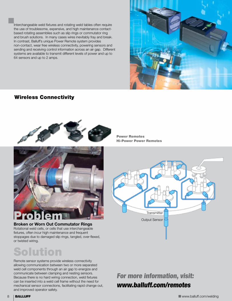
Wireless Connectivity
Interchangeable weld fixtures and rotating weld tables often require the use of troublesome, expensive, and high maintenance contact-based rotating assemblies such as slip rings or commutator ring and brush solutions. In many cases wires inevitably fray and break. In contrast, Balluff’s unique Power Remote system provides non-contact, wear free wireless connectivity, powering sensors and sending and receiving control information across an air gap. Different systems are available to transmit different levels of power and up to 64 sensors and up to 2 amps.
Broken or Worn Out Commutator RingsRotational weld cells, or cells that use interchangeable fixtures, often incur high maintenance and frequent stoppages due to damaged slip rings, tangled, over-flexed, or twisted wiring.
SolutionRemote sensor systems provide wireless connectivity allowing communication between two or more separated weld cell components through an air gap to energize and communicate between clamping and nesting sensors. Because there is no hard wiring connection, weld fixtures can be inserted into a weld cell frame without the need for mechanical sensor connections, facilitating rapid change out, and improved operator safety.
Problem
For more information, visit: www.balluff.com/remotes
Transmitter
Output Sensor
Power Remotes Hi-Power Power Remotes

�
ww
w.b
alluff
.com
Robot Zone Limit Systems
Save time, money, and effort with robot zone limit kits from Balluff. Whether you need 1, 2, or 3-axis rotary, or linear top loaders and RTUs, Balluff’s pre-engineered, fully functional kits are the fastest solution. Our kits are ready to install on popular robot models manufactured by Fanuc, Motoman, and Nachi, and are ready to interface with your safety monitoring circuitry for an easy DLD light curtain muting solution. Mechanical limit switch and inductive non-contact versions are available for both new robotic builds and as a retrofit upgrade for existing robots.
Increased Safety within Robotic Weld CellsOperators working in robot welding installations need to be continuously protected from the equipment during loading and unloading sequences.
SolutionBalluff robot zone limit safety systems are rated for multi-axis movement. They can be set up to work with or without a light curtain, and provide freedom of movement within desig-nated zones. This prevents the robot from entering the zone or stopping the robot if the operator enters the robot’s zone of operation.
In Figure 1, the robot is free to work only in the right hand zone because the operator is standing outside of that zone. The robot is prevented from operating in the left zone because the operator on the left is working in that zone.
In Figure 2, the operator on the right has entered the zone, while the oper-ator on the left has withdrawn. Now the robot is free to operate solely in the left hand zone and can not enter the right hand zone.
In Figure 3, both operators are working in their zones, automatically immobilizing the robot.
Problem
Pre-Engineered Automation System: Fanuc ArcMate Robot with Lincoln Electric Welding Package, featuring the Balluff zone limit system.
For more information, visit: www.balluff.com/robotzonelimit

10 www.balluff.com/welding
Weld Audit Notes

11
ww
w.b
alluff
.com
Achieve Maximum Performance in Your Welding Process with Balluff Industry Sensor Services Balluff Industry Sensor Services can go a long way in analysis of your own weld cell productivity, where dramatic decreases in unplanned machine down time can be realized with short ROI payback time intervals. All of this is accomplished through audit training first, then through physical upgrade of your weld cell sensor systems. You say you’re understaffed to do the job right? Balluff Outfitters can upgrade your sensor system point by point to ensure long sensor performance and increase productivity and profitability.
Weld Cell Audit Servicen Expert analysis of all problematic sensor “hotspots” on your plant floorn Timely and tailored recommendations for weld cell process improvementsn Provide your company with a “roadmap” towards significantly reducing unplanned downtime, greatly reducing material consumption, and increasing profitability
Weld Cell Training Services n Integrate the welding industry’s Best Practices n Proactively maintain nesting, clamping, and error proofing sensing devices in the weld celln Bunker and protect all sensing system components to ensure the longest possible life of these systems
Balluff Sensor Outfitters n Does understaffing prevents your company from upgrading your welding cells? n Team of “hands on” experts come and install the industry’s Best Practices sensor system (sensors, heavy duty bunkers, connectivity, protective jacketing) n Get your weld cells running with dramatically reduced unplanned machine down time
Sensor Outfitters Overview
Logo-CMYK
Examples of common weld cell problems that we've solved:
Weld Repel® Wrap, clear silicone jacket-ing, and TPE cables provide flexibility and resistance to weld slag, lubricants, and connector burn-through.
Unprotected and non-bunkered sensors, sensors in damage-prone areas, and/or lighweight brackets.
Bunker Blocks™ and SlagMaster® coating allow full protection against harsh impact.
Damage to unprotected sensor faces and cables caused by impact and contact.
Slag accumulation and unprotected pigtail sensors cause large amounts of downtime.
PTFE coated Prox-Mounts and Weld Repel® covered sacraficial cables improve sensor life and productivity.

1� www.balluff.com/welding
SlagMaster®
SlagMaster® coating significantly prolongs sensor life by providing a thermal barrier to protect against heat, retarding build up of weld slag spatter and spray, and easing removal of surrounding deposits of weld debris during scheduled maintenance periods.
The parts listed below are non-weld field immune sensors and do not offer PTFE coating. For PTFE coated weld field immune sensors, see pages 14-17.
For the most up to date parts list, visit: www.balluff.com/slagmaster.
InductiveSensors
Part Numbers & Specifications
Balluff Part Number Housing Diameter
Sensing Distance
(mm)
Mounting Output Logic
Housing Material Drawing Wiring Diagram
10..30VDC, Non-Weld Field Immune
BES 516-324-SA96-G-E5-C-S 4 M8 2 F PNP, N/O Nickel plated brass 1 A
BES 516-324-SA96-G-E5-C-S49 M8 2 F PNP, N/O Nickel plated brass 2 A
BES 516-343-SA96-G-E5-C-S49 M8 2 F NPN, N/O Nickel plated brass 2 B
BES M08MH1-NSC20B-S04G-101 M8 2 F NPN, N/O Nickel plated brass 3 B
BES 516-325-SA96-G-E5-Y-S 4 M12 4 F PNP, N/O Nickel plated brass 4 A
BES 516-325-SA96-G-S4-C M12 4 F PNP, N/O Nickel plated brass 4 A
BES 516-329-SA96-G-E5-Y-S 4 M12 4 F NPN, N/O Nickel plated brass 5 B
BES 516-326-SA96-G-E5-Y-S 4 M18 8 F PNP, N/O Nickel plated brass 6 A
BES 516-355-SA96-G-E5-Y-S 4 M18 8 F NPN, N/O Nickel plated brass 6 B
BES R01ZC-PSC70B-BX00.2-GS04-101 20x32 7 F PNP, N/O GD-Zn 7 A
BES R01ZC-PSC70B-BX00.2-GS49-101 20x32 7 F PNP, N/O GD-Zn 8 A
BES R01ZC-PSC70B-BX05-101 20x32 7 F PNP, N/O GD-Zn 9 A
High Temperature 120°C, Non-Weld Field Immune
BES 516-324-SA55-03 M8 2 F PNP, N/O Stainless steel 10 A
BES 516-325-SA68-03 M12 2 F PNP, N/O Nickel plated brass 11 A
BES 516-105-SA9-S4 M18 5 F PNP/Comp Nickel plated brass 12 D
BES 516-347-SA13-03 25x50x10 5 F PNP, N/O GOAlSi12 13 A
2-Wire DC, 10…30VDC, Polarized, Normally Open, Non-Weld Field Immune
BES M08MG-GSC20B-BP00.3-GS04-101 M8 2 F 2-wire Nickel plated brass 14 C
BES M12MG-GSC30B-BP00.3-GS04-101 M12 3 F 2-wire Nickel plated brass 15 C
BES M18MG-GSC70B-BP00.3-GS04-101 M18 7 F 2-wire Nickel plated brass 16 C
BES M30MF-GSC15B-BP00.3-GS04-101 M30 15 F 2-wire Nickel plated brass 17 C
BES R01ZC-USC50B-BP00.2-G-S04-101 20x23 5 F 2-wire GD-Zn 7 E
F = Flush, NF = Non-flush, QF = Quasi-flush Pigtail sensors available with preinstalled Weld Repel® tubing. Contact factory for availability.
B
C
DAPNP, N/O
NPN, N/O
PNP, Comp
Polarized N/O
NPN, N/O
E

1�
ww
w.b
alluff
.com
InductiveSensors
M8x1
3044
13
LED
M8x1
4565
LED
13
M12x1
5030
17
LED
1 2 3 4 5
M18x1
29.5
44.5
24
LED
6 7 8
M8x1
25.5
55.5
13
LED
11
M12x1
Technical Drawings
9
14 15 16 17
10
55.5
M8x1
Ø3.3
13
11 12 13
M12x1
17
40.5
75
Ø10.5
Ø9.7
Ø10.7
Ø5.1
6073
83
M18x1
24
M12x1
<Ø16.7
508
10
1025
153
Ø7.
2
Ø4.
2Ø7
Sensing face

1� www.balluff.com/welding
Weld Field Immune
Magnetic field immune (weld-immune) inductive sensors are used for work-piece positioning in welding areas where strong magnetic fields influence ordinary sensors’ oscillator/coil systems. This leads to false switching when no target is present.
Balluff magnetic field immune inductive sensors can be mounted in the direct vicinity of welding tongs or electrodes, since welding currents of up to 25 kA do not affect the switching function of the sensor.
These parts are available with SlagMaster® coating.
magnetic field
currentconductor sensor
Weld Field ImmuneInductiveSensors
Part Numbers & Specifications
Balluff Part Number Housing Diameter
SensingDistance
(mm)
Mounting Housing Material
SlagMaster®
Coated FaceDrawing Wiring
Diagram
10...30 Vdc, PNP, Normally Open
BES 516-325-S4-W M12 2 F PTFE Coated Brass 1 A
BES 516-325-SA96-S4-W M12 2 F PTFE Coated Brass n 1 A
BES 516-356-S4-W M12 4 NF PTFE Coated Brass 2 A
BES 516-326-S4-W M18 5 F PTFE Coated Brass 3 A
BES 516-326-SA96-S4-W M18 5 F PTFE Coated Brass n 3 A
BES 516-360-S4-W M18 8 NF PTFE Coated Brass 4 A
BES 516-327-S4-W M30 10 F PTFE Coated Brass 5 A
BES 516-327-SA96-S4-W M30 10 F PTFE Coated Brass n 5 A
BES 516-362-S4-W M30 15 NF PTFE Coated Brass 6 A
BES R01ZC-PSC50B-BX03-V 20x32 5 F GD-Zn 7 A
BES R01ZC-PSC50B-BX05-W01 20x32 5 F GD-Zn n 7 A
BES R01ZC-PSC50B-BX____-GS04-V* 20x32 5 F GD-Zn 8 A
BES R01ZC-PSC50B-BX00.2-GS04-W01 20x32 5 F GD-Zn n 8 A
BES R01ZC-PSC50B-BX00.2-GS04-W11 20x32 5 F GD-Zn w/Al backplate n 8 A
BES R01ZC-PSC50B-BX____-GS49-V* 20x32 5 F GD-Zn 9 A
BES 517-385-M3-CW-S 40x40 15 F PBT 10 A
BES 517-385-M3-CW-S-S4 40x40 15 F PBT 11 A
20…250V AC/DC, Normally Open
BES 516-211-S21-EL-W M18 5 F PTFE Coated Brass 12 B
BES 516-211-SA96-S21-EL-W M18 5 F PTFE Coated Brass n 12 B
BES 516-211-S5-EL-W M18 5 F PTFE Coated Brass 13 B
BES 516-211-SA96-S5-EL-W M18 5 F PTFE Coated Brass n 13 B
BES 516-211-S5-EL-W-SA1 M18 5 F PTFE Coated Brass 14 B
10...30 Vdc, PNP, Normally Open, 2x
BES M12MI-PSC30B-S04G-W M12 3 F PTFE Coated Brass 15 A
BES M12MI-PSC30B-S04G-W01 M12 3 F PTFE Coated Brass n 15 A
BES M18MI-PSC70B-S04G-W M18 7 F PTFE Coated Brass 16 A
BES M18MI-PSC70B-S04G-W01 M18 7 F PTFE Coated Brass n 16 A
F = Flush, NF = Non-flush, QF = Quasi-flush
*Please specify the cable length forsensors with cable and connector.00.2, 00.5 = Irradiated PUR, length 0.2 m or 0.5 M
Pigtail sensors available with preinstalled Weld Repel® tubing. Contact factory for availability.

1�
ww
w.b
alluff
.com
M12x1
404061
1717
LED LED
M12x1 5
404061
1717
M18x1
3010
55
24
LED
LED
3010
55
M30x1.5
36
Weld Field Immune InductiveSensors
1 2 3 4 5
6 7 8 9
10 11 12
13 14
Technical Drawings
A
PNP, N/O
1
2
3
GR N
RD/BL K
RD/WH
B
AC/DC
PX0
663c
40
30
40
LED Ø5.
3
7.3
7.3
6.5
120
12.5
6046
40
13 16
120
6046 40
30
40
LED Ø5.
3
7.3
7.3
6.5
M20x1.5
40
13 16
PX1
550c
15 16
M12x1
LED
6550
M12x1
LED
1717

1� www.balluff.com/welding
Factor 1Factor 1
Balluff Factor 1 sensors have special dual coil electronic circuitry whose function is unaffected by strong magnetic fields found in processes such as induction hardening and welding environments. They also come equipped with PTFE coated housings resistant to weld splatter.
Factor 1 sensors sense all metals at the same distance. There is no need to derate the sensing distance based on target material.
These parts are available with SlagMaster® coating.
magnetic field
currentconductor sensor
InductiveSensors
Part Numbers & Specifications
Balluff Part Number
Housing Diameter
Sensing Distance
(mm)
Mounting
Output Logic
Housing Material
SlagMaster® Coated Face
Drawing
Wiring Diagram
BES M12MF1-PSC30A-S04G-W M12 3 F PNP, N/O PTFE Coated Brass 2 A
BES M12MF1-PSC30A-S04G-W01 M12 3 F PNP, N/O PTFE Coated Brass n 2 A
BES M12ML-PSC30A-S04G-W M12 3 F PNP, N/O PTFE Coated Brass 1 A
BES M12ML-PSC30A-S04G-W01 M12 3 F PNP, N/O PTFE Coated Brass n 1 A
BES M12ML-PSC80E-S04G-W M12 8 N PNP, N/O PTFE Coated Brass 3 A
BES M12ML-PSC80E-S04G-W01 M12 8 N PNP, N/O PTFE Coated Brass n 3 A
BES M12MD1-PSC80E-S04G-W M12 8 N PNP, N/O PTFE Coated Brass 4 A
BES M12MD1-PSC80E-S04G-W01 M12 8 N PNP, N/O PTFE Coated Brass n 4 A
BES M18ML-PSC50A-S04G-W M18 5 F PNP, N/O PTFE Coated Brass 5 A
BES M18ML-PSC50A-S04G-W01 M18 5 F PNP, N/O PTFE Coated Brass n 5 A
BES M18MF1-PSC50A-S04G-W M18 5 F PNP, N/O PTFE Coated Brass 6 A
BES M18MF1-PSC50A-S04G-W01 M18 5 F PNP, N/O PTFE Coated Brass n 6 A
BES M18ML-PSC12E-S04G-W M18 12 N PNP, N/O PTFE Coated Brass 7 A
BES M18ML-PSC12E-S04G-W01 M18 12 N PNP, N/O PTFE Coated Brass n 7 A
BES M18MD-PSC12E-S04G-W M18 12 N PNP, N/O PTFE Coated Brass 8 A
BES M18MD-PSC12E-S04G-W01 M18 12 N PNP, N/O PTFE Coated Brass n 8 A
BES M30ML-PSC10A-S04G-W M30 10 F PNP, N/O PTFE Coated Brass 9 A
BES M30ML-PSC10A-S04G-W01 M30 10 F PNP, N/O PTFE Coated Brass n 9 A
BES M30ML-PSC20E-S04G-W M30 20 N PNP, N/O PTFE Coated Brass 10 A
BES M30ML-PSC20E-S04G-W01 M30 20 N PNP, N/O PTFE Coated Brass n 10 A
BES Q40KFU-PAC15A-S04G 40X40 15 F PNP, Comp PBT 11 B
BES Q40KFU-PAC15A-S04G-W01 40X40 15 F PNP, Comp PBT n 11 B
BES Q40KFU-PSC15A-S04G 40X40 15 F PNP, N/O PBT 11 A
BES Q40KFU-PSC15A-S04G-W01 40X40 15 F PNP, N/O PBT n 11 A
BES Q40KFU-PAC20A-S04G 40X40 20 F PNP, Comp PBT 11 B
BES Q40KFU-PSC20A-S04G 40X40 20 F PNP, N/O PBT 11 A
BES Q40KFU-PAC35E-S04G 40X40 35 N PNP, Comp PBT 11 B
BES Q40KFU-PAC35E-S04G-W01 40X40 35 N PNP, Comp PBT n 11 B
BES Q40KFU-PSC35E-S04G 40X40 35 N PNP, N/O PBT 11 A
BES Q40KFU-PSC35E-S04G-W01 40X40 35 N PNP, N/O PBT n 11 A
BES Q40KFU-PAC40E-S04G 40X40 40 N PNP, Comp PBT 11 A
www.balluff.com/welding

1�
ww
w.b
alluff
.com
Factor 1 InductiveSensors
M18x1
50.5
65
LED
24
1 2 3 4 5
LED
M18x1
35
50
24
M18x1
5540
.510
24
LEDLED
6550
.5
M30x1.5
36
LED
5237
.513
M30x1.5
36
6 7 8 9 10
40x40
11 12
Q40 Mounting Guidelines
Sensing Distance Sn Sensor with...
15 mm Original bracket (plastic) Yes Yes Yes Yes Yes Yes Yes Yes
Optional BES Q40-HW-2 (metal) Yes Yes Yes Yes Yes Yes Yes Yes
20 mm Original bracket (plastic) Yes Yes Yes Yes Yes Yes Yes Yes
Optional BES Q40-HW-2 (metal) Yes Yes Yes Yes Yes Yes Yes Yes
35 mm Original bracket (plastic) No No No Yes No Yes Yes Yes
Optional BES Q40-HW-2 (metal) No No No Yes No Yes No No
35 mmBES...35Z...011
Original bracket (plastic) No No Yes Yes Yes Yes Yes Yes
Optional BES Q40-HW-2 (metal) No No No Yes No Yes No Yes
40 mm Original bracket (plastic) No No No Yes No Yes No Yes
Optional BES Q40-HW-2 (metal) No No No Yes No Yes No No
Technical Drawings
A
PNP, N/O
B
PNP, Comp

1� www.balluff.com/welding
InductiveSensors
SteelFace®
Balluff SteelFace® sensors are the go-to sensors for harsh sensing environments. Their one piece gun drilled stainless steel housings stand up to major incidental impacts, their long range characteristics combined with PTFE coatings give them long term survivability in tough weld cell applications, and their price/performance ratio is the best in the market.
Part Numbers & Specifications
Up to 1.0 mm thick impact and abrasion resistant face
One-piece solid stainless steel construction
Balluff Part Number Housing Diameter
Sensing Distance (mm)
Mounting Output Logic
PTFE Coated
Housing Material
Drawing Wiring Diagram
2X Extended Range Product Family (All units 10-30Vdc) (Non-PTFE coated available, remove 01 suffix)*
BES M08EH1-PSC20B-S04G-S01 M8 2 F PNP, N/O n SS 316 1 A
BES M08EH1-NSC20B-S04G-S01 M8 2 F NPN, N/O n SS 316 1 B
BES M12EI-PSC40B-S04G-S01 M12 4 F PNP, N/O n SS 316 2 A
BES M12EI-NSC40B-S04G-S01 M12 4 F NPN, N/O n SS 316 2 B
BES M18EI-PSC72B-S04G-S01 M18 7.2 F PNP, N/O n SS 316 3 A
BES M18EI-NSC72B-S04G-S01 M18 7.2 F NPN, N/O n SS 316 3 B
3X Extended Range Product Family (All units 10-30Vdc)
BES M12EG1-PSC60Z-S04G-S11 M12 6 QF PNP, N/O SS 316 4 A
BES M12EG1-NSC60Z-S04G-S11 M12 6 QF NPN, N/O SS 316 4 B
BES M12EF1-PSC10F-S04G-S M12 10 NF PNP, N/O SS 316 5 A
BES M12EF1-NSC10F-S04G-S M12 10 NF NPN, N/O SS 316 5 B
BES M18EG1-PSC10Z-S04G-S11 M18 10 QF PNP, N/O SS 316 6 A
BES M18EG1-NSC10Z-S04G-S11 M18 10 QF NPN, N/O SS 316 6 B
BES M18EF1-PSC20F-S04G-S M18 20 NF PNP, N/O SS 316 7 A
BES M18EF1-NSC20F-S04G-S M18 20 NF NPN, N/O SS 316 7 B
BES M30EG1-PSC20Z-S04G-S11 M30 20 QF PNP, N/O SS 316 8 A
BES M30EG1-NSC20Z-S04G-S11 M30 20 QF NPN, N/O SS 316 8 B
BES M30EE1-PSC40F-S04G-S M30 40 NF PNP, N/O SS 316 9 A
BES M30EE1-NSC40F-S04G-S M30 40 NF NPN, N/O SS 316 9 B
Ferrous-only Sensing SteelFace® Product Family (10-30Vdc) (Non-ferrous available)
BES M08EG1-PSC15S-S04G-S M8 1.5 F PNP, N/O SS 303 10 A
BES M08EG1-NSC15S-S04G-S M8 1.5 F NPN, N/O SS 303 10 B
BES M12EG1-PSC20S-S04G-S M12 2 F PNP, N/O SS 303 11 A
BES M12EG1-POC20S-S04G-S M12 2 F PNP, N/C SS 303 11 C
BES M12EG1-NSC20S-S04G-S M12 2 F NPN, N/O SS 303 11 B
BES M18EG1-PSC50S-S04G-S M18 5 F PNP, N/O SS 303 12 A
BES M18EG1-POC50S-S04G-S M18 5 F PNP, N/C SS 303 12 C
BES M18EG1-NSC50S-S04G-S M18 5 F NPN, N/O SS 303 12 B
BES M30EG1-PSC80S-S04G-S M30 8 F PNP, N/O SS 303 13 A
BES M30EG1-NSC80S-S04G-S M30 8 F NPN, N/O SS 303 13 B
Ferrous-only Sensing SteelFace® Product Family (20-250Vac/300Vdc) (Non-ferrous available)
BES M12EN1-USU20S-S21G-S M12 2 F AC/DC, N/O SS 303 14 D
BES M18EP1-USU50S-S21G-S M18 5 F AC/DC, N/O SS 303 15 D
F = Flush, NF = Non-flush, QF = Quasi-flush*Use steel Prox Mounts when Prox Mounts are selected, see page 24
®

1�
ww
w.b
alluff
.com
InductiveSensors
1 2 3 4 5
6 7 8 9 10
11 12 13 14 15
M12x1
½”-20
17
267
83
LED 1LED 2
24
M18X1
½”-20
2.5
66.5
87.5LED 1
LED 2
�Ø10.5
LEDM12x1
6544.5
13
M8x1
11.8 Ø10.5 LED
M12x1
49.5
65
17
M12x1
6550
M18x1
24
M12x1
<Ø10.5 LED
<Ø10.5
LED
M12x1
4160
17
M12x1
5
63.5
42
M18x1
24
M12x1
<Ø16.4
LED
7
LED
63.550
M30x1.5
10
36
M12x1
<Ø27.5
Technical Drawings
PNP, N/O
A
NPN, N/O
B
Mounting Guidelines Each SteelFace® family of sensors has unique mounting requirements. Please contact the factory for additional mounting information.
C
1
2
3
GR N
RD/BL K
RD/WH
D
PNP, N/C
AC/DC
®

�0 www.balluff.com/welding
Balluff Part Number*,** Input Voltage Output Logic Connector Type Drawing Wiring Diagram
BES 516-300-S 295/0.912”...4.560”-S4 10...30 Vdc PNP, N/O M12 7 A
BES 516-200-S 2/0.912”...4.560”-S21 20...250 Vac/Vdc AC/DC, N/O 1/2” UNF-20-2A 7 C
BES 516-300-S 2/0.912”...4.560”-S5 20...250 Vac/Vdc AC/DC, N/O 7/8”-16 UN 7 C
StrokeMaster®
Balluff high-pressure cylinder sensors are designed to sense the “spud” or cushion of a high pressure pneumatic or hydraulic cylinder’s piston to indicate clamped or unclamped cylinder gripping jaw positions. Rated to 3000 psi, these embedded inductive, WFI sen-sors are commonly found in heavy duty welding applications such as automotive and Tier supplier welding environments. StrokeMaster® sensors are available to accommodate many cylinder bore diameters in both AC/DC and in DC formats to meet many welding electrical requirements.
Example: Need probe length of 1.125” com-bine sensor BES-516-200-S2-1.35-S21 with a 0.225” spacer (1.35” tube length - 0.225” spacer = 1.125” adjusted length).
Note: A difference of 0.005” will still have to be carefully considered when sizing a spacer and sensor to the cylinder.- Spacer kits include a spacer, “O” ring, and appropriate mounting screws.- Other spacer kits may be available; consult factory.
To order a spacer kit: Use part number BESA-516-20-KIT-* (X.XXX) measured in inches. (For both DC and AD/DC devices, there is no difference in flange dimensions.)
Balluff Part Number Specialty Mode Output Logic Connector Type
Drawing Wiring Diagram
BMF 305M-PS-C-2-S4* Metal Body Only PNP, N/O M12 1 A
BMF 305M-PS-C-2-S49* Metal Body Only PNP, N/O M8 2 A
BMF 305M-PS-C-2-SA4-S49* Extended Temperature PNP, N/O M8 2 A
BMF 305M-PS-W-2-S4* WFI PNP, N/O M12 1 A
BMF 315M-PS-W-2-S04-00.3 WFI PNP, N/O Pigtail M12 4 A
BMF 315M-PS-W-2-S49-00.3 WFI PNP, N/O Pigtail M8 5 A
BMF 315M-PS-W-2-PU-05 WFI PNP, N/O 5 m Cable 6 A
BMF 315M-PS-D-2-SA3-S49-00.3 Extended Temperature PNP, N/O Pigtail M8 5 A
BMF 315M-PS-D-2-SA3-PU-05 Extended Temperature PNP, N/O 5 m Cable 6 A
BMF 32M-PS-W-2-S4* WFI PNP, N/O M12 3 A
BMF 32M-NS-W-2-S4* WFI NPN, N/O M12 3 B
* Requires additional bracketry, visit www.balluff.com/bmf Pigtail sensors available with preinstalled Weld Repel® tubing. Contact factory for availability.
Magnetoresistive Sensors
Ineffective Reed or Hall Effect switches, often provide inaccurate clamped or unclamped position information for pneumatic cylinders used in weld cells. An upgrade to Balluff BMF magnetoresistive sensors will provide more accurate position information over time. BMF sensors are available for virtually every cylinder configuration. They increase machine up-time, lower stocking requirements, and are guaranteed for life.
Cylinder & Clamp
Know your cylinder?Find your sensor.For more information, visit: www.balluff.com/bmf.
*Lengths available: 0.912, 1.025, 1.13, 1.25, 1.35, 1.5, 1.75, 1.875, 2.062, 2.375, 2.775, 2.875, 3.775, 4.56
**150+ other lengths available with the use of spacer kits. (Consult chart below for sizes.)
Part Numbers & Specifications
Z/Spacers (inches)
Pro
be L
engt
h (in
ches
)
0.18 0.188 0.225 0.307 0.372 0.375 0.5 0.544 0.562 0.6 0.684 0.712 0.81 0.937
0.912 0.732 0.724 0.687 0.605 0.540 0.537 0.412 0.368 0.350 0.312 0.228 0.200 0.102 ——
1.025 0.845 0.837 0.800 0.718 0.653 0.650 0.525 0.481 0.463 0.425 0.341 0.313 0.215 0.088
1.25 1.070 1.062 1.025 0.943 0.878 0.875 0.750 0.706 0.688 0.650 0.566 0.538 0.440 0.313
1.35 1.170 1.162 1.125 1.043 0.978 0.975 0.850 0.806 0.788 0.750 0.666 0.638 0.540 0.413
1.5 1.320 1.312 1.275 1.193 1.128 1.125 1.000 0.956 0.938 0.900 0.816 0.788 0.690 0.563
1.75 1.570 1.562 1.525 1.443 1.378 1.375 1.250 1.206 1.188 1.150 1.066 1.038 0.940 0.813
1.875 1.695 1.687 1.650 1.568 1.503 1.500 1.375 1.331 1.313 1.275 1.191 1.163 1.065 0.938
2.062 1.882 1.874 1.837 1.755 1.690 1.687 1.562 1.518 1.500 1.462 1.378 1.350 1.252 1.125
2.375 2.195 2.187 2.150 2.068 2.003 2.000 1.875 1.831 1.813 1.775 1.691 1.663 1.565 1.438
2.775 2.595 2.587 2.550 2.468 2.403 2.400 2.275 2.231 2.213 2.175 2.091 2.063 1.965 1.838
2.875 2.695 2.687 2.650 2.568 2.503 2.500 2.375 2.331 2.313 2.275 2.191 2.163 2.065 1.938
3.775 3.595 3.587 3.550 3.468 3.403 3.400 3.275 3.231 3.213 3.175 3.091 3.063 2.965 2.838
4.56 4.380 4.372 4.335 4.253 4.188 4.185 4.060 4.016 3.998 3.960 3.876 3.848 3.750 3.623

�1
ww
w.b
alluff
.com
Input Voltage Output Logic Connector Type Drawing
BES Z02KR2-PSC20F-P*-S04-V PNP, N/O M12 8
BES Z02KR1-PSC20F-P*-S04-V PNP, N/O M12 9
BES Z02KR3-PSC20F-P*-S04-V PNP, N/O M12 10
*Lengths Available: P100 = 100 mm, P165 = 165 mm, P200 = 200 mm
9 10
Power Clamp & Gripper Sensing
Many newer generation power clamp mechanisms integrate a dual inductive proximity sen-sor “chicklet” configuration joined to a common mounting housing with one common DC micro electrical outlet into their clamp indication system. These inductive proximity sensors sense the passing of steel components passing by the inductive fields to indicate clamped or unclamped jaw position. Balluff power clamp sensors are available to accommodate a wide range of power clamp mechanical configurations and electrical requirements.
6 7 8
20C
able
leng
th
18
17
47LED 1LED 2LED 3
6.5
Cylinder & Clamp
½”UNF-20-2A or M12
64
.2
7/8”-16 UN
LED 1
LED 2
30
25
35
48
O-ring 17.13 X 2.62
UNC 1/4”-20X3/4” 12.9
L8
51
37
Ø1
2.7
304º
1 2 3 4 5
Technical Drawings
1
A
PNP, N/O
B
NPN, N/O
1
2
3
GR N
RD/BL K
RD/WH
C
AC/DC, N/O
�� www.balluff.com/welding
PhotoelectricSensors
Photoelectric
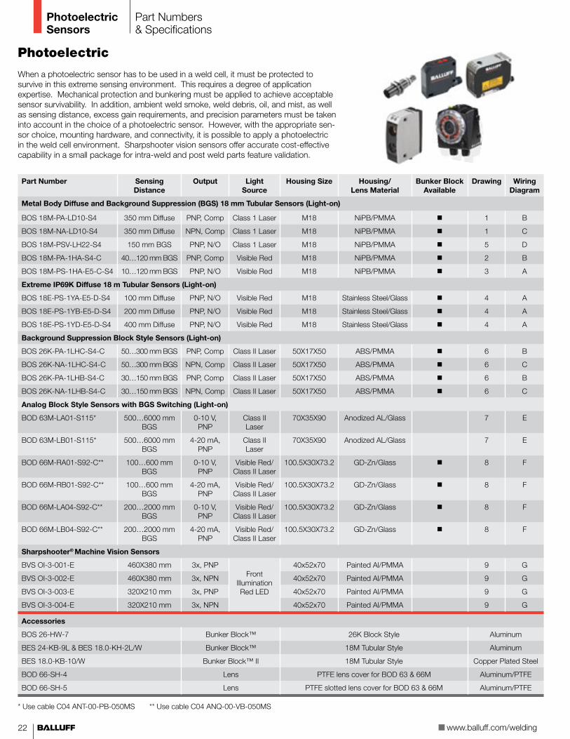
When a photoelectric sensor has to be used in a weld cell, it must be protected to survive in this extreme sensing environment. This requires a degree of application expertise. Mechanical protection and bunkering must be applied to achieve acceptable sensor survivability. In addition, ambient weld smoke, weld debris, oil, and mist, as well as sensing distance, excess gain requirements, and precision parameters must be taken into account in the choice of a photoelectric sensor. However, with the appropriate sen-sor choice, mounting hardware, and connectivity, it is possible to apply a photoelectric in the weld cell environment. Sharpshooter vision sensors offer accurate cost-effective capability in a small package for intra-weld and post weld parts feature validation.
Part Number Sensing Distance
Output Light Source
Housing Size Housing/ Lens Material
Bunker Block Available
Drawing Wiring Diagram
Metal Body Diffuse and Background Suppression (BGS) 18 mm Tubular Sensors (Light-on)
BOS 18M-PA-LD10-S4 350 mm Diffuse PNP, Comp Class 1 Laser M18 NiPB/PMMA n 1 B
BOS 18M-NA-LD10-S4 350 mm Diffuse NPN, Comp Class 1 Laser M18 NiPB/PMMA n 1 C
BOS 18M-PSV-LH22-S4 150 mm BGS PNP, N/O Class 1 Laser M18 NiPB/PMMA n 5 D
BOS 18M-PA-1HA-S4-C 40…120 mm BGS PNP, Comp Visible Red M18 NiPB/PMMA n 2 B
BOS 18M-PS-1HA-E5-C-S4 10…120 mm BGS PNP, N/O Visible Red M18 NiPB/PMMA n 3 A
Extreme IP69K Diffuse 18 m Tubular Sensors (Light-on)
BOS 18E-PS-1YA-E5-D-S4 100 mm Diffuse PNP, N/O Visible Red M18 Stainless Steel/Glass n 4 A
BOS 18E-PS-1YB-E5-D-S4 200 mm Diffuse PNP, N/O Visible Red M18 Stainless Steel/Glass n 4 A
BOS 18E-PS-1YD-E5-D-S4 400 mm Diffuse PNP, N/O Visible Red M18 Stainless Steel/Glass n 4 A
Background Suppression Block Style Sensors (Light-on)
BOS 26K-PA-1LHC-S4-C 50…300 mm BGS PNP, Comp Class II Laser 50X17X50 ABS/PMMA n 6 B
BOS 26K-NA-1LHC-S4-C 50…300 mm BGS NPN, Comp Class II Laser 50X17X50 ABS/PMMA n 6 C
BOS 26K-PA-1LHB-S4-C 30…150 mm BGS PNP, Comp Class II Laser 50X17X50 ABS/PMMA n 6 B
BOS 26K-NA-1LHB-S4-C 30…150 mm BGS NPN, Comp Class II Laser 50X17X50 ABS/PMMA n 6 C
Analog Block Style Sensors with BGS Switching (Light-on)
BOD 63M-LA01-S115* 500…6000 mmBGS
0-10 V, PNP
Class II Laser
70X35X90 Anodized AL/Glass 7 E
BOD 63M-LB01-S115* 500…6000 mmBGS
4-20 mA, PNP
Class II Laser
70X35X90 Anodized AL/Glass 7 E
BOD 66M-RA01-S92-C** 100…600 mm BGS
0-10 V,PNP
Visible Red/ Class II Laser
100.5X30X73.2 GD-Zn/Glass n 8 F
BOD 66M-RB01-S92-C** 100…600 mmBGS
4-20 mA,PNP
Visible Red/ Class II Laser
100.5X30X73.2 GD-Zn/Glass n 8 F
BOD 66M-LA04-S92-C** 200…2000 mmBGS
0-10 V,PNP
Visible Red/ Class II Laser
100.5X30X73.2 GD-Zn/Glass n 8 F
BOD 66M-LB04-S92-C** 200…2000 mmBGS
4-20 mA,PNP
Visible Red/ Class II Laser
100.5X30X73.2 GD-Zn/Glass n 8 F
Sharpshooter® Machine Vision Sensors
BVS OI-3-001-E 460X380 mm 3x, PNP Front
Illumination Red LED
40x52x70 Painted Al/PMMA 9 G
BVS OI-3-002-E 460X380 mm 3x, NPN 40x52x70 Painted Al/PMMA 9 G
BVS OI-3-003-E 320X210 mm 3x, PNP 40x52x70 Painted Al/PMMA 9 G
BVS OI-3-004-E 320X210 mm 3x, NPN 40x52x70 Painted Al/PMMA 9 G
Accessories
BOS 26-HW-7 Bunker Block™ 26K Block Style Aluminum
BES 24-KB-9L & BES 18.0-KH-2L/W Bunker Block™ 18M Tubular Style Aluminum
BES 18.0-KB-10/W Bunker Block™ II 18M Tubular Style Copper Plated Steel
BOD 66-SH-4 Lens PTFE lens cover for BOD 63 & 66M Aluminum/PTFE
BOD 66-SH-5 Lens PTFE slotted lens cover for BOD 63 & 66M Aluminum/PTFE
Part Numbers & Specifications
* Use cable C04 ANT-00-PB-050MS ** Use cable C04 ANQ-00-VB-050MS

��
ww
w.b
alluff
.com
PhotoelectricSensors
1 2 3 4
7
5038
4
4
4.3
4150
4.3
6
8
5
Technical Drawings
����
���
�
��
�
�� �������������
� ��
��������������
��
����������������
��
F
E
M18x1
48
75
24
53
M12x1
Ø16.7
Red LEDYellow LED
Sn
ReceiverEmitter
7.1
3.7
B
PNP, Comp
A
PNP, N/O
C
NPN, N/O & N/C
1243
BNWHBKBU -0 V
OutError+10...30 V DCD
PNP, N/O, Error Output
9
G Visit www.balluff.com/sharpshooter for wiring information

�� www.balluff.com/welding
Accessories
Accessories
Balluff’s Weld Repel® sensor protection solution provides total protection not only for the sensor, but for the connector and cable as well. This complete protection package will yield the weld cell a significant increase in productivity because the sensor and its associated connectivity will last far longer than a similar unprotected or poorly protected sensor and cable. The same excellent protection is found in area protection sheets for draping large surfaces. Protecting valve banks, large collections of cables, air lines, weld pedestals, and robots becomes easy with silicone area protection sheets.
The Balluff Bunker Block™ with a quick-change Prox Mount protects the sensor body and face from abusive physical damage. Since the Bunker Block™ is made of machined aluminum and the Prox Mount is PTFE-coated, the entire system repels weld slag buildup. The copper clad, all steel Bunker Block® II offers excellent loading impact and compliments Balluff 2X SteelFace sensors in the toughest welding applications. The SlagMaster® coating on the face of the proximity sensor can also repel weld slag accumulation and protect the sensor face from damage even in severe welding environments. To connect the sensor, start with a TPE cable which has high durability, and then cover the cable with the Weld Repel® system. This system uses a medical grade silicone jacket to protect the cable and a sili-cone wrap to secure the jacket in its proper location while sealing remaining connectivity components against harsh, hot weld spray. Pre-installed Weld Repel® jacketing over select TPE cables are available. Please consult factory for additional information.
Part Numbers & Specifications
TPE Cables
C04 AEL-00-TY-050M M12 Straight female, 4-wire, 5 m
C04 BEL-00-TY-050M M12 Right angle female, 4-wire, 5 m
C04 AEH-00-TY-050M M12 Straight female, 3-wire, PNP LED, 5 m
C04 BEH-00-TY-050M M12 Right angle female, 3-wire, PNP LED, 5 m
C49 ANE-00-TY-050M-2 M8 Straight female, 3-wire, 5 m
C49 BNE-00-TY-050M-2 M8 Right angle female, 3-wire, 5 m
C21 AE3-00-TY-150F 1/2” X 20 UNF Straight female, 3-pin dual keyway, 15 ft
C21 BE3-00-TY-150F 1/2” X 20 UNF Right angle female, 3-pin dual keyway, 15 ft
Other cables available, consult factory for more information.
The Weld Select Series from Balluff is the ultimate solution for increasing productivity and decreasing sensor failure.
Prox Mounts
PTFE (White) Coated Brass Short Proxes (≥30mm)
PTFE (White) Coated Brass Long Proxes (≥40mm)
PTFE (Black) Coated Steel Proxes (≥30mm)
Outter Diameter
Inner Diameter
BES 08.0-KH-2S/W BES 08.0-KH-2L/W BES 08.0-KH-11S/W M12x1 8 mm
BES 12.0-KH-2S/W BES 12.0-KH-2L/W BES 12.0-KH-11S/W M16x1 12 mm
BES 12.0-KH-2S/W-M18 BES 12.0-KH-11S/W-M18 M18x1 12 mm
BES 18.0-KH-2S/W BES 18.0-KH-2L/W BES 18.0-KH-11S/W M24x1.5 18 mm
BES 30.0-KH-2S/W BES 30.0-KH-2L/W M36x1.5 30 mm

Connectivity
��
ww
w.b
alluff
.com
Part Numbers & Specifications
Weld Repel® Jacket
BKS-PT-7/16-SI-15 Clear silicone tubing, 1/4” dia. x 50 ft (15 m)
BKS-PT-10/16-SI-15 Clear silicone tubing, 3/8” dia. x 50 ft (15 m)†
BKS-PT-13/16-SI-15 Clear silicone tubing, 1/2” dia. x 50 ft (15 m)††, *
BKS-PT-16/16-SI-15 Clear silicone tubing, 5/8” dia. x 50 ft (15 m)**
BKS-PT-19/16-SI-15 Clear silicone tubing, 3/4” dia. x 50 ft (15 m)
BKS-PT-38/16-SI-07.5 Clear silicone tubing, 1/5” dia. x 25 ft (15 m)
BKS-PT-50/16-SI-07.5 Clear silicone tubing, 2” dia. x 25 ft (15 m)
* Recommended for use with M12 (micro) single ended cables** Recommended for use with M12 (micro) double ended cables† Recommended for use with M8 (nano) single ended cables†† Recommended for use with M8 (nano) single ended cables
SlagMaster® recommended. See pages 12-17.
Weld Repel® Wrap
BKS PW-26/20-SI-TR-03,5 1” wide x 12 ft Clear silicone wrap
BKS PW-51/30-SI-TR-11 2” wide x 36 ft Clear silicone wrap
Weld Repel® Area Protection
BKS S-PS-914/16-SI 3 ft x custom length in ft
BKS S-PS-914/16-SI-00,91 3 ft x 3 ft sheet
Bunker Block® II without positive stop
Copper Plated Steel Description
BES 08.0-KB-10/W M8 sensors
BES 12.0-KB-10/W M12 sensors
BES 18.0-KB-10/W M18 sensors
BES 30.0-KB-10/W M30 sensors
Bunker Block®
Machined AL Prox Mount Required Description
BES 12.0-KB-9L BES 08,0-KH-2L/W M8 sensors (40 mm+)
BES 16.0-KB-9L BES 12,0-KH-2L/W M12 sensors (40 mm+)
BES 24.0-KB-9L BES 18,0-KH-2L/W M18 sensors (40 mm+)
BES 36.0-KB-9L BES 30,0-KH-2L/W M30 sensors (40 mm+)
BES 12.0-KB-9S BES 08,0-KH-2S/W M8 sensors (short)
BES 16.0-KB-9S BES 12,0-KH-2S/W M12 sensors (short)
BES 24.0-KB-9S BES 18,0-KH-2S/W M18 sensors (short)
BES 36.0-KB-9S BES 30,0-KH-2S/W M30 sensors (short)

AccessoriesPart Numbers & Specifications
Aluminum Clamp with Positive Stop
BES 08,0-KB-4-F AL clamp for M8 sensors
BES 12,0-KB-4-F AL clamp for M12 sensors
BES 18,0-KB-4-F AL clamp for M18 sensors
BES 30,0-KB-4-F AL clamp for M30 sensors
Q40 & 26K Sensor Accessories
BES Q40-HW-2 Metal mounting bracket
BES Q40-SH-1 AL protection cover
BES Q40-SH-2 PA6 protection cover
BOS 26-HW-7 BOS 26K Bunker Block®
Protective Caps
BES 12-CERAMIC-CAP-1 Ceramic for M12 sensors
BES 18-CERAMIC-CAP-1 Ceramic for M18 sensors
BES 30-CERAMIC-CAP-1 Ceramic for M30 sensors
BES _ _ -SM-4 PTFE caps for Prox Mounts (12, 16, 24, 36)
Heavy Duty Prox Actuator Plunger
BES JPH-0.625-12-1.50 Prox plunger for M12 sensors
WELD Jacket
WELD-JACKET-1/2” Silicone & fiberglass 1/2” diameter (by the foot)
WELD-JACKET-3/4” Silicone & fiberglass 3/4” diameter (by the foot)
Additional Accessories
Balluff offers many accessories designed to survive in the welding environment. These offerings are very effective at protecting and increasing sensor and connectivity life. Covers, caps, plungers, and clamps are all designed to help protect the sensor from damage. Metal connectivity accessories allow for heavy duty applications in the harshest environments, while Weld Jacket is another option in the fight to protect cables from damage. All of the products listed below will help reduce sensor failure and increase sensor life expectancy.
www.balluff.com/welding��
Air Blow-off Accessories & Air Knife
BOS 12-LT-1 Air blow-off for M12 sensors
BOS 18-LT-1 Air blow-off for M18 sensors
BMS CZ M-D-18-1001 Air knife
R01 Flatpack Sensor Accessories
BES R01-SH-4-A Over-the-top, retro-fit bunker block
BES R01-SH-4-B Socket style bunker block (for new installations)
BES R01ZC-TC PTFE protective cover

Cordsets, MIBs Networking
Metal Multiple Interface Blocks (with PNP LEDs)
BSB-04-F01P/4-M02M-KP-* 4 port MIB, cable out
BSB-04-F01P/4-M01M-2319 4 port MIB, QD homerun cable
BSB-04-F01P/8-M02M-KP-* 8 port MIB, cable out
BSB-04-F01P/8-M01M-2319 8 port MIB, QD homerun cable
CM 23_1 N8-00-PB-100M QD homerun cable, 10 m
* 05 (5 m cable) or 10 (10 m cable)1 = A (straight) or B (90°)
ww
w.b
alluff
.com
��
Connectivity
Stop Wasting Sensors and select your sensor based on application
Change the Paradigm and use sensor and cable protection systems
Reduce Downtime by installing SlagMaster® and SteelFace® sensors
Slash Consumption by protecting with Weld Repel® Jacket and Wrap
Boost Profitability through extending sensor life
Networking and Passive Connectivity
The Balluff line of welding products now includes a family of passive and active multiple interface blocks and modules, which allows the end-user to consolidate multiple I/O points to one location. Typically, these products are plastic and non-potted, but Balluff’s blocks and modules are IP67, fully potted and metal housed, allowing them to survive in the toughest environments. The active modules commu-nicate on DeviceNet and Profibus and for ease of troubleshooting they contain the largest and most visible LEDs in the industry and provide all the needed diagnostic data demanded in today’s industries. Balluff’s Networking and Passive connectivity products complete the total welding solution from the sensor to the controls cabinet.
DeviceNet Modules
BNI DNT-104-00-Z004 16 input only
BNI DNT-202-00-Z005 8 output only
BNI DNT-302-00-Z005 16 configurable
BNI DNT-305-00-Z005 8 in/8 out
Profibus Modules
BNI PBS-104-000-Z004 16 input only
BNI PBS-302-000-Z001 16 configurable
A full line of networking and auxiliary power cables are available. Visit www.balluff.com or consult factory for more details.

No. 1
5550
7 · E
ditio
n 05
2008
· 07
43 ·
Repl
aces
edi
tion
0620
07 ·
Prod
uct
spec
ifica
tions
, ava
ilabi
lity,
and
pric
ing
are
subj
ect t
o ch
ange
with
out n
otic
e.
USABalluff Inc.8125 Holton DriveFlorence, KY 41042Phone: (859) 727-2200Toll-free: 1-800-543-8390Fax: (859) 727-4823E-Mail: [email protected]
CanadaBalluff Canada, Inc.2840 Argentia Road, Unit #2Mississauga, Ontario L5N 8G4Phone: (905) 816-1494Toll-free: 1-800-927-9654Fax: (905) 816-1411E-Mail: [email protected]
MexicoBalluff de Mexico S.A. de C.VProl. Av. Luis M. Vega #109Col. Ampliacion CimatarioQueretaro, QRO 76030Phone: (++52 442) 212-4882, 224-3583, 224-3171Fax: (++52 442) 214-0536E-Mail: [email protected]
Object Detection
Linear Position and Measurement
Industrial Identification
Networking and Connectivity
Accessories
www.balluff.com/welding