tardir/mig/a309328 - DTIC
28
NASA TECHNICAL NOTE sO sO NASA TN D-6696 in 19960607 155 DESIGN PROPERTIES OF RANDOMLY REINFORCED FIBER COMPOSITES by Christos C. Chamis Lewis Research Center Cleveland, Ohio 44135 ( % >* NATIONAL AERONAUTICS AND SPACE ADMINISTRATION • WASHINGTON, D. C. . MARCH 19Wy^ a .*....- ..:,) :. . , * ~i
Transcript of tardir/mig/a309328 - DTIC

NASA TECHNICAL NOTE
sO sO
NASA TN D-6696
in
19960607 155 DESIGN PROPERTIES OF RANDOMLY REINFORCED FIBER COMPOSITES
by Christos C. Chamis
Lewis Research Center
Cleveland, Ohio 44135 (%>*
NATIONAL AERONAUTICS AND SPACE ADMINISTRATION • WASHINGTON, D. C. . MARCH 19Wy^
■ a .*....-■■ ..:,)■■:.■.
, * ~i

THIS DOCUMENT IS BEST
QUALITY AVAILABLE. THE
COPY FURNISHED TO DTIC
CONTAINED A SIGNIFICANT
NUMBER OF PAGES WHICH DO
NOT REPRODUCE LEGIBLY.

1. Report No.
NASA TN D-6696 2. Government Accession Nc
4. Title and Subtitle
DESIGN PROPERTIES OF RANDOMLY REINFORCED
FIBER COMPOSITES
7. Author(s)
Christas C. Chamis
9. Performing Organization Name and Address
Lewis Research Center National Aeronautics and Space Administration
Cleveland, Ohio 44135 12. Sponsoring Agency Name and Address
National Aeronautics and Space Administration
Washington, D.C. 20546
3. Recipient's Catalog No.
5. Report Date
March 1972 6. Performing Organization Code
8. Performing Organization Report No.
E-6569 10. Work Unit No.
134-14
11. Contract or Grant No.
13. Type of Report and Period Covered
Technical Note
14. Sponsoring Agency Code
15. Supplementary Notes
16. Abstract
The pseudoisotropic-laminate analogy is used in conjunction with fiber composite micro- and macromechanics to predict the thermal and mechanical properties of planar randomly reinforced fiber composites (PRRFC). Theoretical results are presented for boron/aluminum, boron/epoxy, Thornel-50/epoxy, and S-glass/epoxy PRRFC. The results show that the thermal and elastic properties depend on both constituent materials and the fiber volume ratio. The strength depends also on the type of applied stress. In general, no simple ratio exists between the properties of unidirectional fiber composites and those of PRRFC. The data are presented in convenient graphical form to serve as an aid for design and/or analysis and also for further research in PRRFC. The residual stresses and the impact resistance are also theoretically examined.
17. Key Words (Suggested by Authoi (s))
Random fiber composites; Pseudoisotropic laminate analogy; Boron/aluminum; Boron/epoxy; Thornel- 50/epoxy; S-glass/epoxy; Theoretical design data; Thermomechanical properties; Residual stress-, Impact resistance; Structural mechanics
Distribution Statement
Unclassified - unlimited
19. Security Classif. (of this report)
Unclassified
20. Security Classif. (of this page)
Unclassified
21. No. of Pages
25
22. Price
$3.00
1 Fui sale by [lib National Technical InlothicitTOH-Sorvicc^.Springfield. Vii^inu 22101

DESIGN PROPERTIES OF RANDOMLY REINFORCED FIBER COMPOSITES
by Christos C. Chamis
Lewis Research Center
SUMMARY
The pseudoisotropic-laminate analogy is used in conjunction with fiber composite micro- and macromechanics to predict the thermal and mechanical properties of planar randomly reinforced fiber composites (PRRFC). The thermal properties consist of the heat capacity, the inplane and through-the-thickness heat conductivities, and the thermal coefficient of expansion. The mechanical properties consist of the elastic properties (normal modulus, shear modulus, and Poisson's ratio) and the strength properties (ten- sile, compressive, and shear strengths). In addition, the residual stress and the impact resistance of PRRFC are examined as well as specific properties for modulus, strength,
and impact resistance. It is well known that PRRFC and pseudoisotropic laminates are elastically equiva-
lent. However, they are not equivalent with respect to strength in general. It is theo- retically demonstrated in this report that the strength of PRRFC equals the minimum strength of the pseudoisotropic laminate. Subsequently, ,the pseudoisotropic-laminate analogy is used to generate the aforementioned properties as a function of fiber volume ratio (FVR) for boron/aluminum, boron/epoxy, Thornel-50S/epoxy, and S-glass/epoxy PRRFC. These data are presented in convenient graphical form for analysis and/or de- sign. The data can also serve as a guide for further research in PRRFC.
The theoretical results show that the thermal and elastic properties of PRRFC de- pend on the composite system and FVR. The strength properties depend also on the type of applied stress. The ratio of the modulus of the PRRFC to that of unidirectional com- posites is about 1/3 for composites with fiber-matrix modulus ratio (Ef/Em) greater than 20. No unique ratio exists for strength. The pseudoisotropic-laminate analogy is the most effective method for predicting the thermomechanical properties of PRRFC.
INTRODUCTION
Planar randomly reinforced fiber composites (PRRFC) are of interest in certain structural applications because they offer two primary advantages: (1) they can provide

stiffness, strength, and hardness (in the macrosense) for multiple load directions at considerable weight savings over conventional materials; (2) they offer ease of fabrica- tion of complex components. Some examples are jet engine air splitters and seals, gears, wheels, brakes, and pump housings. Another indirect but important advantage has to do with the production costs of fibers and prepreg tape. That is, defective runs and/or remnants from continuous tape production can be used effectively and efficiently to fabricate randomly reinforced composites.
Thermal and mechanical characterizations of random composites are required to design structural components from these materials. The characterization can be done in at least four ways: (1) testing (refs. 1 and 2); (2) statistical averaging of fiber dis- tribution (refs. 3 to 5) or interfiber bonding (ref. 6); (3) integration of unidirectional properties (refs. 7 to 10 and author's unpublished notes); and (4) use of the pseudoisotropic- (quasi-isotropic) laminate analogy (refs. 11 to 13). The first requires an extensive and perhaps cost-prohibitive amount of testing. The second usually leads into complex mathematical formalisms with some inconsistencies (ref. 4). The third might require certain approximations (ref. 10) or numerical integrations (ref. 8) and neglects the adjacent material contributions. The fourth is the most versatile because it is applicable to all thermal and all mechanical properties. And, in addition, it draws on the extensively developed technologies for micromechanics and laminate analyses. It is perhaps the most natural since the fibers have to be of considerable length for effi- cient utilization (ref. 14).
The potential of the pseudoisotropic-laminate analogy for characterizing PRRFC has not been fully recognized in the fiber composite technology community as yet. Its usage has been limited to the prediction of some elastic and some thermal constants for a few specific composites (refs. 12 and 13).
It is the objective of this investigation to use the pseudoisotropic-laminate analogy in conjunction with micro- and macromechanics to characterize PRRFC. The charac- terization consists of the thermal elastic and strength properties of several typical com- posites. These properties are presented in graphical form as a function of fiber volume ratio. Results for impact resistance and lamination residual stresses are also pre- sented. References are cited where the correspondence between pseudoisotropic lami- nates and PRRFC is theoretically examined.
THEORETICAL CONSIDERATIONS
Planar randomly reinforced fiber composites and pseudoisotropic laminates are thermoelastically isotropic in their plane. They are said to be thermoelastically equiva- lent. It is this equivalence which enables one to use laminate theory to characterize

planar randomly reinforced composites. This is referred to as the pseudoisotropic- laminate analogy. A brief description of the procedure follows.
Possible ply orientation combinations which will yield pseudoisotropic elastic be- havior are described in reference 15 in terms of n-fold symmetry lines. The simplest orientation combination, for example, is a [0, 60, -60] laminate. This laminate lacks reflection-about-a-plane symmetry and will bend upon stretching and thus yield errone- ous measured data. The difficulty is overcome by constructing a laminate with the fol- lowing combination of ply orientations: [0, 60, -60, -60, 60, 0]. Application of laminate theory (ref. 16) to this laminate yields its thermoelastic properties. Such predictions are in good agreement with experimental data. (See, for example, ref. 17, pp. 161 and 173.) The aforementioned laminate is not pseudoisotropic with respect to strength. That is, the strength of the laminate will depend on both load direction, say with respect to 0° plies, and the type of load, for example, tensile, compressive, or shear. It can be shown theoretically (author's unpublished data) that the [0, 60, -60, -60, 60, 0] lami- nate will have both a minimum and a maximum strength. The minimum is obtained when the load direction coincides with one of the ply orientations and the maximum when the load direction bisects the angle of two adjacent ply orientations.
It can be shown both theoretically and by numerical computation that the minimum strength of pseudoisotropic laminates as defined in reference 18 is independent of the number of ply orientation combinations. This is an important finding since it provides a lower bound on the strength of pseudoisotropic laminates. It can be shown by numeri- cal computation that the maximum strength of pseudoisotropic laminates approaches a lower bound as the number of ply orientation combinations increases. This is illustrated graphically in figure 1, where the failure stress is plotted as a function of the number of plies for several pseudoisotropic laminates.
A PRRFC is, in essence, a pseudoisotropic laminate with a large number of ply orientation combinations. Therefore, the strength of the PRRFC must be equal to or greater than the strength lower bound of pseudoisotropic laminates. The establishment of this condition enables us to utilize fiber composite micro- and macromechanics and laminate theory to predict the thermal, elastic, and strength properties of PRRFC. In the subsequent discussion the terms pseudoisotropic and random are used interchange-
ably. The numerical results to be presented and discussed in this report were generated
by using the computer code of reference 16. This code generates ply and laminate properties from input constituent properties. Code-generated unidirectional composite properties of the composite systems investigated are shown in table I for one fiber vol- ume ratio. The strength of the pseudoisotropic laminate was taken to be equal to the ap- plied stress which produced failure in at least one of the plies as predicted by the combined-stress failure criteria described in reference 18.

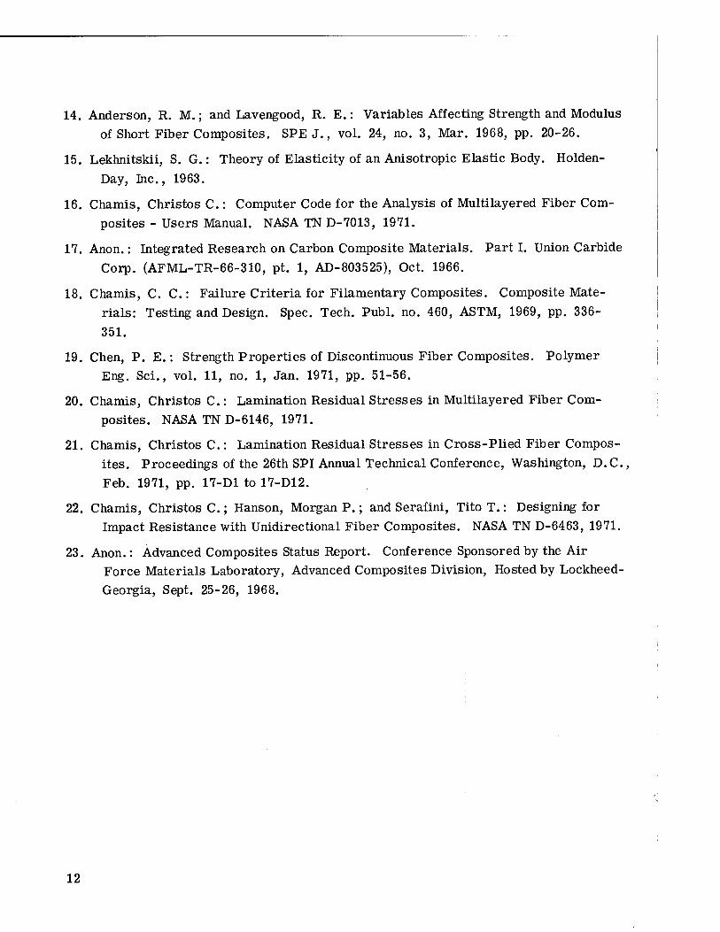
Comparisons of the strengths of some random composites with some special com- posites are instructive. In figure 2, the pseudoisotropic composite strength is com- pared with the uniaxial strength of Thornel-50S/epoxy composites. The results are plotted as a function of fiber content. As can be seen in this figure, the strengths of the pseudoisotropic composites lie between the transverse and the longitudinal strengths of the unidirectional composites and depend on the type and sense of applied stress. It should be noted that the random composite tensile or compressive strength averages about one-third of the corresponding unidirectional composite longitudinal strength. However, the shear strength of the random composite is about 50 percent of its tensile strength. This percentage is approximately the same for isotropic homogeneous ductile materials. Comparisons of random-composite strength with special-composite strength are shown in figure 3 as a function of load angle. As can be seen in this figure, random composites are stronger than some directional composites for certain load angles. Comparisons of random and unidirectional boron/aluminum composites are shown in figure 4 as a function of the load angle. Both currently available and anticipated im- proved unidirectional composite properties are plotted in this figure. The strength of a high-strength aluminum alloy is also shown in figure 4. As can be seen in this figure, the random composite has a strength about 60 percent of that of the high-strength alumi- num alloy. This result indicates that random reinforced boron/aluminum composites are not efficient if they are strength critical.
RANDOM-COMPOSITE CHARACTERIZATION DATA
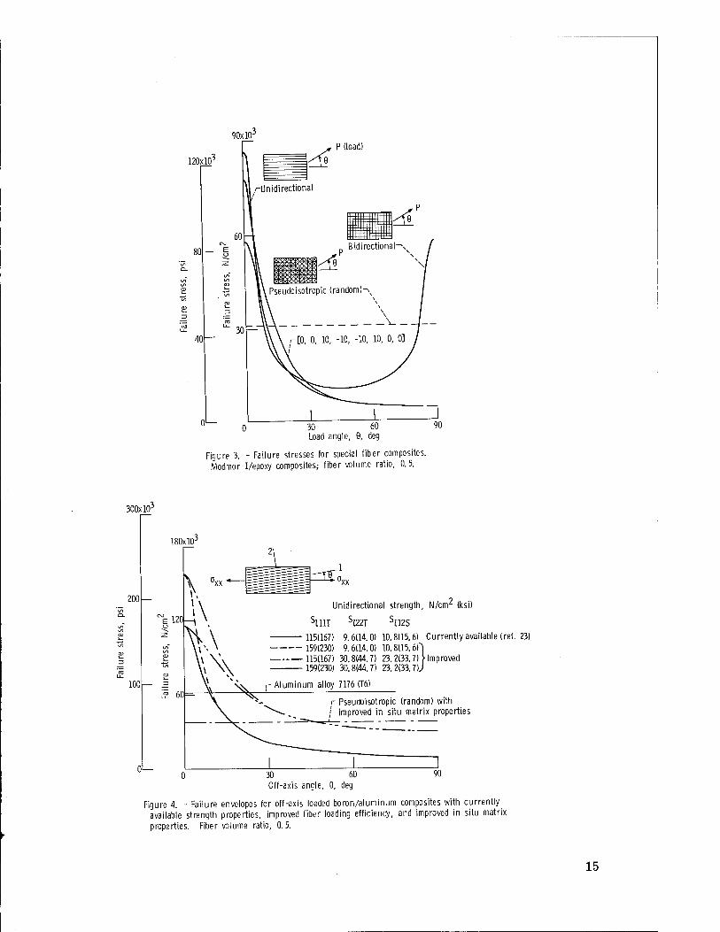
Characterization data were generated for the following four composite systems by using the computer code of reference 16: boron/aluminum, boron/epoxy, Thornel-50S/ epoxy, and S-glass/epoxy. The characterization data include weight density, thermal and elastic properties, and unidirectional strength as a function of fiber volume ratio. Data for residual stresses and impact energy density are also included. The weight density of the four composite systems is shown in figure 5 as a function of fiber volume ratio.
Thermal Properties
The heat capacities of the four random composite systems are shown in figure 6 as a function of fiber volume ratio. The corresponding heat conductivities for inplane and through-the-thickness heat transfer are shown in figures 7 and 8, respectively. In heat- transfer analyses both of these heat conductivities are required since it is possible to have heat flowing in the plane and through the thickness of the composite. It is interest-

ing to note that the inplane heat conductivities for the random composite are the algebraic averages of the longitudinal and transverse heat conductivities. Compare corresponding values from table I and figure 7. This observation agrees with the results obtained by the integration method (author's unpublished data).
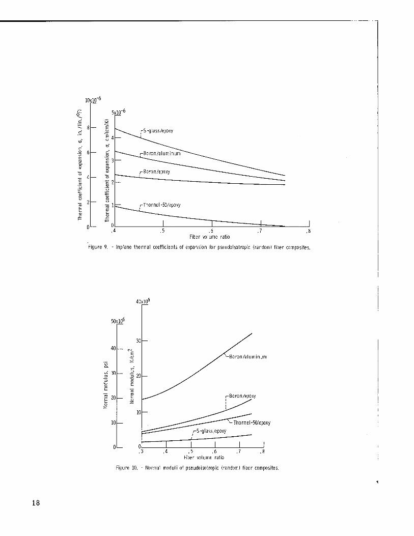
The thermal coefficients of expansion are plotted in figure 9 as a function of FVR for the four random composite systems. It is noted in passing that these results are smaller in general than those obtained by the integration method. The results predicted by the integration method are the algebraic averages of longitudinal and transverse val- ues. The reason for the discrepancy is that the integration method does not account for the restraint provided by adjacent plies. The unrestrained condition assumed with the integration method is not compatible with the physical situation of PRRFC. Even the use of the finite element method as described in reference 19, while representative for the ply, needs implementation to account for adjacent ply restraining effects.
Elastic Properties
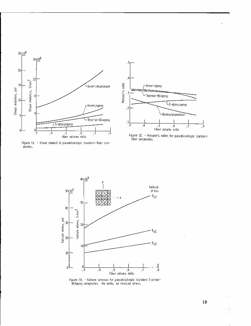
The normal modulus is plotted in figure 10 as a function of the FVR for the four random-composite systems. Analogous results for shear modulus and Poisson's ratio are plotted in figures 11 and 12, respectively. It can be verified by direct substitution that corresponding FVR results from figures 10, 11, and 12 satisfy the isotropic mate- rial elastic constants condition E = 2(1 + v)G.
It is noted that elastic constant values obtained by integration (refs. 8, 9, and author's unpublished data) do not always satisfy this condition. The statistical methods proposed in references 3 and 4 fail to satisfy the isotropic elastic materials condition. It can be seen in figure 12 that the Poisson's ratio of the nonmetallic matrix composites varies slightly with fiber volume ratio.
One very important point to be kept in mind is that the 1/3 ratio of E /E;l1 does not apply to fiber composites with relatively stiff matrixes (Ef/E < 10). This observa- tion can be directly verified by comparing corresponding FVR results from table I and figure 10. However, the 1/3 ratio applies to composite systems with Ef/E greater than 20.
Strength Properties
In the following strength calculations, both the void and residual stress effects were neglected. These effects can be easily investigated by using the computer code of refer- ence 16. The magnitudes of the residual stresses are treated in the section RESIDUAL STRESSES.

Failure stresses (strengths), obtained as described in the section THEORETICAL CONSIDERATIONS, are shown in figure 13 as a function of FVR for a Thornel-50/epoxy random composite. As can be seen, the strengths are for applied tensile, compressive, and shear stresses. Corresponding results for Thornel-50S (treated fiber)/epoxy are shown in figure 14. A significant point is observed by comparing corresponding FVR results from figures 13 and 14. This comparison shows that the treated fiber composites have compressive and shear strengths about twice those of the untreated fiber and also a 15-percent increase in the tensile strength. This increase in strength is a result of in- creases in the ply transverse tensile and intralaminar shear strengths of the treated fiber composite. A point to be made at this juncture is the following: Statistical methods which assume that either the fiber (ref. 4) or the interfiber bond (ref. 6) supplies all the strength in PRRFC cannot account for the increase in strength shown by the treated fibers.
An additional important point to be made is the significant difference between the tensile and compressive strengths. This significant difference is reported here for the first time. It can be predicted neither by the statistical methods proposed in references 3, 4, and 6 nor by the integration method suggested in reference 10. The reason these methods cannot predict the significant difference in tensile and compressive strength is
that they do not account for the five distinct strengths (S,-^™ S,11(~,, SJOOT' ^/22C> and S,..„a) of the ply (unidirectional composite). (Symbols are defined in the appendix.) An integration method can be evolved to account for the five distinct ply strengths (author's unpublished data). However, this method does not include the restraining ef- fects of adjacent plies and thus overpenalizes the random composite strength. As a re- sult of this discussion the following general observation can be made: An integration method which is based on the unidirectional composite only has inherently three disad- vantages: (1) it does not account for adjacent ply strengthening effects; (2) it does not utilize the proven laminate theory; and (3) it requires numerical integration.
The failure stress is plotted against FVR for applied tensile, compressive, and shear stresses in figure 15 for the random boron/epoxy composite, in figure 16 for the S-glass/epoxy composite, and in figure 17 for the boron/aluminum composite.
The three important points to be noted from the results in these figures are (1) Boron/epoxy composites attain a maximum strength at FVR which is different
for each applied stress. Also an optimum FVR exists for these composites if they are to be subjected to both tensile and compressive loads (fig. 15).
(2) Random S-glass/epoxy composites are quite inefficient when compared to the unidirectional-composite longitudinal strength (table I and fig. 16).
(3) Considerable increases in the failure stress of random boron/aluminum com- posites can be effected by improving the ply transverse and shear strengths (fig. 17).
Comparing strength values from table I with corresponding FVR values in figures

14 to 17 leads to the conclusion that no unique strength ratio of the form (random- composite strength)/(unidirectional-composite strength) exists. This ratio appears to
vary between 10 and 40 percent.
RESIDUAL STRESSES
A residual stress state is inherent in PRRFC. This residual stress state is a re- sult of the fabrication process and depends on the composite processing and use temper- ature difference (ref. 20). Invoking the pseudoisotropic analogy, the procedures de- scribed in reference 20 can be used to predict the residual stress state in PRRFC.
The residual stresses in the random-composite systems investigated in this report are plotted against FVR in figure 18. The sense of the residual stress is shown in the schematic in the figure. The residual transverse stress is tensile, and the longitudinal is compressive. However, they both are of equal magnitude. The residual stresses in figure 18 are for temperature differences of 500 K (900° F) for boron/aluminum and 166 K (300° F) for the other composites. As can be seen in this figure, the residual transverse stresses are significant; they attain magnitudes comparable to corresponding
ply strengths (see S,22T values in table I).
The presence of residual stresses in PRRFC will affect their load carrying ability depending on several factors: relative temperature difference, type of applied stress, and amount of residual stress relaxation. Specific cases can be investigated as de- scribed in reference 21.
TENSILE IMPACT
The tensile impact resistance of PRRFC can be estimated by using concepts ad- vanced in reference 22. Plots of impact energy density against FVR are shown in fig- ure 19 for the composite systems investigated in this report.
It can be seen from the results in figure 19 that random boron/epoxy composites are efficient at FVR less than 0. 5, while the Thornel-50S/epoxy composites are efficient at FVR greater than 0. 5. The decrease of impact resistance of the boron/epoxy composite after 0.4 FVR is due to the rapid decreases in its ply transverse and intralaminar shear strengths with increasing FVR (see ref. 22).
SPECIFIC PROPERTIES
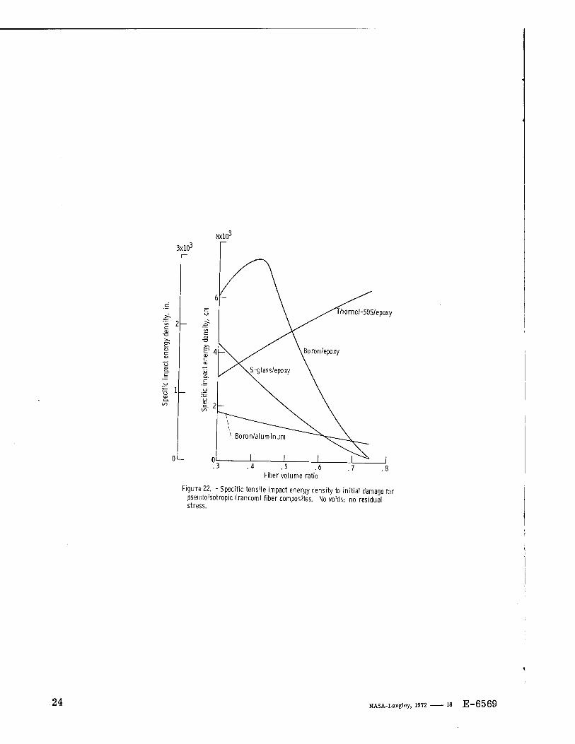
In feasibility studies and preliminary designs, the specific properties (property/ weight density) are of interest. Plots of specific modulus, tensile strength, and tensile
7

impact against FVR are shown in figures 20 to 22, respectively, for the composite sys- tems investigated in this report.
The results in these figures indicate that random composites should be made from boron/aluminum for stiffness requirements. For tensile strengths or tensile impact requirements, they should be made from either low FVR (less than about 0.5) boron/ epoxy or from high FVR (X).55) Thornel-50S/epoxy. On a specific modulus (fig. 20) basis, both boron/epoxy and Thornel-50S/epoxy are of about equal merit.
STRENGTH ESTIMATION i
It is possible to predict the failure stress in pseudoisotropic composites when the margin of safety MS of the most critically stressed ply is known. This is done in the following way. Assume that the composite stress a causes the ith ply to be most critically stressed. The MS of the ith ply is defined by
MS = 1 - F(ac, St, Kr 6) (1)
where F(aQ, S^, K^, 0) is the combined-stress strength function (refs. 16 and 18). The composite stress SQ required to fail the most critically stressed ply and,
therefore, the pseudoisotropic composite strength is given by
Sc = —2- if MS / 0 (2) VMS
Sc = ac if MS = 0 (3)
Invoking the pseudoisotropic analogy, equations (2) and (3) are applicable to PRRFC. The following example illustrates the procedure. Given the pseudoisotropic composite [0, 45, -45, 90, 90, -45, 45, 0] with tensile stress oQ = 17.25 newtons per square centi- meter (25 000 psi), the 0° ply the most critically stressed ply, and MS = 0.198. Then the tensile strength is
S =—— = 25 °00 = 56 200 psi or 38. 8 N/cm2
VMS Vo.198

CONCLUSIONS
A study of design properties of randomly reinforced fiber composites lead to the
following conclusions: 1. The most common design properties of planar randomly reinforced composites
(PRRFC) are predicted by using the pseudoisotropic-laminate analogy. 2. When strength is the controlling design variable, only those fiber/matrix com-
binations should be considered whose random composite strength is greater than any
other material from the matrix family. 3. The failure strengths of randomly reinforced boron/epoxy composites attain a
maximum with respect to fiber volume ratio. The maximum-strength fiber volume ratio
is different for tensile, compressive, and shear loads. 4. The failure strengths of randomly reinforced boron/aluminum composites are
practically constant with respect to fiber volume ratio in the range investigated. 5. Randomly reinforced composites have residual stresses due to fabrication pro-
cesses. The residual stresses will affect the load carrying ability of the PRRFC depend-
ing on their specific application. 6. The impact energy density of randomly reinforced isotropic fiber/matrix com-
posites decreases with increasing fiber content, in general, while it increases for those
made with anisotropic fibers. 7. The random composite modulus is approximately one-third of the unidirectional
composite longitudinal modulus in composites with fiber-matrix modulus ratio (Ef/Em) greater than 20. The corresponding strength varies from about 10 to 40 percent.
Lewis Research Center, National Aeronautics and Space Administration,
Cleveland, Ohio, November 19, 1971, 134-14.

APPENDIX-SYMBOLS
E normal modulus
F combined-stress strength function
G shear modulus
H heat capacity
K heat conductivity
KU2 coefficient in combined-stress strength function
KU2 empirical factor in combined-stress strength function
MS margin of safety
5 strength (failure stress)
a thermal coefficient of expansion
6 ply orientation angle
v Poisson's ratio
a stress
Subscripts:
C compression
c planar randomly reinforced fiber composite property
f fiber
I ply or unidirectional composite
m matrix
S shear
T tension
a T or C (tension or compression)
ß T or C (tension or compression)
1, 2,3 material axes directions
10

REFERENCES
1. Toth, L. W.; and Boiler, T. J.: Manufacturing Concepts in Application of Molded Advanced Composites to Aerospace Components. Aircraft Structures and Mate- rials Application. Vol. 1 of National SAMPE Technical Conference. Western Periodicals Co., 1969, pp. 361-368.
2. Lee, Lieng-Huang: Strength-Composition Relationships of Random Short Glass Fiber-Thermoplastics Composites. Polymer Eng. Sei., vol. 9, no. 3, May 1969, pp. 213-224.
3. Cox, H. L.: The Elasticity and Strength of Paper and Other Fibrous Materials. Brit. J. Appl. Phys., vol. 3, Mar. 1952, pp. 72-79.
4. Gordon, J. E.: On the Present and Potential Efficiency of Structural Plastics. J. RoyAeron. Soc., vol. 56, Sept. 1952, pp. 704-728.
5. Cook, J.: The Elastic Constants of an Isotropie Matrix Reinforced With Imperfectly Oriented Fibres. J. Physics, Pt. D, Brit. J. Appl. Phys., Ser. 2, vol. 1, no. 6, June 1968, pp. 799-812.
6. Dodson, C. T. J.: A New Approach to the Fracture of Bonds in a Random Fibrous Network Such as Paper. Brit. J. Appl. Phys., vol. 18, Aug. 1967, pp. 1199-1204.
7. Tsai, Stephen W.; and Pagano, Nicholas J.: Invariant Properties of Composite Ma- terials. Composite Materials Work Shop. S.W. Tsai, J. C. Halpin, and N. J. Pagano, eds., Technomic Publishing Co., 1967, pp. 233-253.
8. Nielsen, L. E.; and Chen, P. E.: Young's Modulus of Composites Filled with Ran- domly Oriented Fibers. J. Materials, vol. 3, no. 2, June 1968, pp. 352-358.
9. Lees, J. K.: A Study of the Tensile Modulus of Short Fiber Reinforced Plastics. Polymer Eng. Sei., vol. 8, no. 3, July 1968, pp. 186-194.
10. Lees, J. K.: A Study of the Tensile Strength of Short Fiber Reinforced Plastics. Polymer Eng. Sei., vol. 8, no. 3, July 1968, pp. 195-201.
11. Bolotin, V. V.: Theory of Reinforced Layered Medium with Random Initial Irregu- larities. Mekhanika Polimerov, vol. 2, 1966, p. 11.
12. Halpin, J. C; and Pagano, N. J.: The Laminate Approximation for Randomly Oriented Fibrous Composites. J. Composite Materials, vol. 3, Oct. 1969, pp. 720-724.
13. Halpin, J. C; Jerine, K.; and Whitney, J. M.: The Laminate Analogy for 2 and 3 Dimensional Composite Materials. J. Composite Materials, vol. 5, Jan. 1971, pp. 36-49.
11
14. Anderson, R. M.; and Lavengood, R. E.: Variables Affecting Strength and Modulus of Short Fiber Composites. SPE J., vol. 24, no. 3, Mar. 1968, pp. 20-26.
15. Lekhnitskii, S. G.: Theory of Elasticity of an Anisotropie Elastic Body. Holden-
Day, Inc., 1963.
16. Chamis, Christos C.: Computer Code for the Analysis of Multilayered Fiber Com- posites - Users Manual. NASA TN D-7013, 1971.
17. Anon.: Integrated Research on Carbon Composite Materials. Part I. Union Carbide
Corp. (AFML-TR-66-310, pt. 1, AD-803525), Oct. 1966.
18. Chamis, C. C: Failure Criteria for Filamentary Composites. Composite Mate- rials: Testing and Design. Spec. Tech. Publ. no. 460, ASTM, 1969, pp. 336-
351.
19. Chen, P. E.: Strength Properties of Discontinuous Fiber Composites. Polymer Eng. Sei., vol. 11, no. 1, Jan. 1971, pp. 51-56.
20. Chamis, Christos C.: Lamination Residual Stresses in Multilayered Fiber Com- posites. NASA TN D-6146, 1971.
21. Chamis, Christos C.: Lamination Residual Stresses in Cross-Plied Fiber Compos- ites. Proceedings of the 26th SPI Annual Technical Conference, Washington, D.C., Feb. 1971, pp. 17-D1 to 17-D12.
22. Chamis, Christos C; Hanson, Morgan P.; and Serafini, Tito T.: Designing for Impact Resistance with Unidirectional Fiber Composites. NASA TN D-6463, 1971.
23. Anon.: Advanced Composites Status Report. Conference Sponsored by the Air Force Materials Laboratory, Advanced Composites Division, Hosted by Lockheed-
Georgia, Sept. 25-26, 1968.
12

TABLE I. - TYPICAL PROPERTIES OF UNIDIRECTIONAL COMPOSITES AS
PREDICTED BY MICROMECHANICS
[From ref. 16; fiber volume ratio, 0.5; zero voids.]
(a) SI Units
Property Boron/aluminum Boron/epoxy Thornel-50S/epoxy S-glass/epoxy
3 Density, p, g/cm 2.63 1.74 1.44 1.80
Heat capacity, H,p, J/(kg/K) 1118 1214 854 816
Coefficient, Km, W/(m/K) 73.9 1.73 41.9 0.66
Coefficient, K^, W/(m/K) 45.5 0.57 0.54 0.40
Thermal coefficient of expansion, 2.36 1.71 -0.07 2.18
u,yt, 10" cm/(cm/K)
Thermal coefficient of expansion, 3.79 9.06 12.89 8.94
°722' 10~ cm/(cm/K)
Modulus, Ej-ti, kN/cm 24.1 20.9 17.4 4.45
Modulus, E,22, kN/cm 16.8 1.2 0.66 1.03
Shear modulus, G,.,, kN/cm 8.0 0.57 0.43 0.60
Poisson's ratio, v,-,« 0.24 0.25 0.25 0.26
Strength, SmT, N/cm2 115 134 80 161
Strength, S,llc, N/cm 125 132 66 124
Strength, S,22T, N/cm 9.6 5.6 4.6 5.6
Strength, S,22c, N/cm 10.5 19.6 13.2 21.3
Strength, S.-gg, N/cm 10.8 8.3 5.2 6.3
Coefficient, K. ,2 0.86 0.94 1.37 0.75
Coefficient, K'12a!g 1.0 1.0 1.0 1.0
(b) U.S. Customary Units
Density, p, lb/in. 0.095 0.064 0.052 0.065
Heat capacity, BIC, Btu/(lb/°F) 0.267 0.290 0.204 0.195
Coefficient, Km, Btu/(hr)(ft2)(°F/in.) 513 12.0 291 4.61
Coefficient, Kl22, Btu/(hr)(ft2)(°F/in.)
Thermal coefficient of expansion,
316
4.24X10"6
3.96
3.07X10"6
3.72
-0.121X10"6
2.75
3.93X10"6
fflZll' in-/(in./°F) Thermal coefficient of expansion, 6.83X10"6 16.3X10"6 23.2X10"6 16.1X10"6
al22' in-/(in-/°F) Modulus, E.j.., psi
Modulus, E,22J Psi
Shear modulus, G,,2, psi
35.0X10⁶
24.3X10⁶
11.6X10⁶
30.3X10⁶
1.8xl06
0.82X10⁶
25.3X10⁶
0.96X10⁶
0.63X10⁶
6.45X10⁶
1.50X10⁶
0.87X10⁶
Poisson's ratio, v,-.* 0.24 0.25 0.25 0.26
Strength, SZ11T, ksi 167 195 116 234
Strength, S,,,^,, ksi 181 192 96 180
Strength, S.22T, ksi 14. 8.1 6.6 8.1
Strength, S,22c, ksi 15.3 28.4 19.1 30.1
Strength, S,12S, ksi 15.6 12.1 7.5 9.1
Coefficient, K.,2 0.86 0.94 1.37 0.75
Coefficient, K'.,^^« 1.0 1.0 1.0 1.0
13

50x10s
60x10s
50
40
30
20
10
40
^ 30
= 20
10
IS i^. Upper bound
J1U ITJUTD J a JT in rr Lower bound
Number Orientation of plies
6 0, ±60j] 8 0, ±45, 90]
12 0, ±30, +60, 90]
16 0, ±22.5, ±45, +67.5, 90|]
20 0, ±18, +36, +54, +72, 90J]
24 0, + 15, +30, ±45, ±60, ±75, ±90|]
12 16 Number of plies
20 24
Figure 1. - Upper and lower bounds for strength of various pseudoisotropic composites from Modmor-1/epoxy at 0.50 fiber volume content with zero voids and no residual stress.
Pseudoisotropic (random) 8[0, 45, -45, 90, 90, -45, 45, 0]
-— Unidirectional 180X103
Failure stress
120
60
120x10s
,' SU1T
.5 .6 Fiber volume ratio
Figure 2. - Comparison of pseudoisotropic (random) and unidirectional composite failure stresses for Thornel-50S/epoxy with zero voids and no residual stresses.
14
P (load)
120x10
40
01— 30 Load angle,
Figure 3. - Failure stresses for special fiber composites. Modmor-I/epoxy composites; fiber volume ratio, 0.5.
300xl03
200
100
IWxW
0>—
Unidirectional strength, N/cnr (ksi)
122T S112S
9.6(14.0) 10.8(15.6) Currently available (ref. 23) 159(230) 9.6(14.0) 10.8(15.6H 115(167) 30.8(44.7) 23.2(33.7) Mm proved
159(230) 30.8(44.7) 23.2(33.7 )J
Pseudoisotropic (random) with improved in situ matrix properties
30 60 Off-axis angle, 0, deg
90
Figure 4. - Failure envelopes for off-axis loaded boron/aluminum composites with currently available strength properties, improved fiber loading efficiency, and improved in situ matrix properties. Fiber volume ratio, 0.5.
15
3.0
. 10r
.09' 2.5
2 .07-
.06-
.05L
2.0
1.5
1.0 .4
Dron/aluminum
S-glass/epoxy
Boron/epoxy
-Thornel-50/epoxy
.5 .6 .7 Fiber volume ratio
Figure 5. - Weight density for pseudoisotropic (random) fiber composites.
.30r
.28-
.26-
1.50x10 ,3
-Boron/epoxy
1.25
.■& . 24 - ■ -& 1.00 -
.22-
.20-
.18
.75 -Thornel-50/epoxy
-S-glass/epoxy
l_ .50L .5 .6 .7
Fiber volume ratio
Figure 6. - Heat capacity for pseudoisotropic (random) fiber composites.
16

500,—
300 -
= 100-
10-
-Boron/aluminum
-Boron/epoxy
,-S-glass/epoxy
.5 .7
Figure
Fiber volume ratio
7. - Inplane heat conductivity for pseudoisotropic (random) fiber composites.
500 r—
£ 300 "
80
60
. 40
20
100 ■
10-
.4
Figure 8.
-Boron/aluminum
S-glass/epoxy oron/epoxy
Thornel-50/epoxy
Fiber volume ratio
Through thickness heat conductivity for pseudoisotropic (random) composites.
17
10x10""'
.2 6
- 4
5x10"'
0
Fiber volume ratio
Figure 9. - Inplane thermal coefficients of expansion for pseudoisotropic (random) fiber composites.
40x10°
minum
Thornel-50/epoxy
.4 .5 .6 .7 .8 Fiber volume ratio
Figure 10. - Normal moduli of pseudoisotropic (random) fiber composites.
18
25x10°
.5 .6 Fiber volume ratio
Figure 11. - Shear moduli of pseudoisotropic (random) fiber com- posites.
.5
.2
/-Boron/epoxy
S-glass/epoxy
Boron/aluminum
.5 .6 Fiber volume ratio
.7
Figure 12. - Poisson's ratios for pseudoisotropic (random) fiber composites.
40xl03
50x10'
40
.30
20
10
30
20
10
.3
X
.5 .6 Fiber volume ratio
.7
Figure 13. - Failure stresses for pseudoisotropic (random) Thornel 50/epoxy composites. No voids; no residual stress.
19

zmo/N 'ss9j)s 8jn|]Bj
!sd 'ss8j)s 9jn|]Bj
7ui3/N 'SS9JJS ajniiej
S
p
CD
en L?\
ISd 'SS3JJS 9Jn|IBJ
20

30xl03
40xl05
20
.5 .6 Fiber volume ratio
Figure 16. - Failure stresses for pseudoisotropic (random) S-glass/ epoxy composites. No voids; no residual stress.
60X103
40
20
MxlO3
30
i= 20
10
Typical
Failure stress
>cT
>cC
\S
With improved unidirectional composite transverse and shear properties (see fig. 4)
.4 .5 .6 Fiber volume ratio
Figure 17. - Failure stresses for pseudoisotropic (random.) boron/aluminum composites. No voids; no residual stress.
21

e 'S —. CD 3 .2
"^ "5 \ 1 c o \ <W
1_ ■—
o en J
\ o i-""% \ .c \ t— \ J
s? O
O CD a.
t/1 c ra
e V o JS uo
1 Is- V. 1 /l \ 1
—
E
,o
n CD
E O
CD F — o
,W0/([\|)(W3) '^|SU9p Ä6J8U9 pedW| S E
£ •ui/(q|)cu|) 'fysuap «U9U9 pedw|
,uio/l\l 'ssajjs |Bnp|say
oo r ■° C3 ^,
e E l/l cu
-8 3
O 1—
."S
t/> X CD cn.
_L" o LJ-
Cl> CD v-> CD rc\
■o
Cl> ^ ^o
13 1 '
'tS) CD to
' g ™ ™ 23 ^ LT .E o CD ^Q-, CD i; E S E .|S2S
|sd 'SS9JJS lenpisay
22

600x10°
400
200
1200x10'
o1—
^Boron/aluminum
.5 .6 Fiber volume ratio
Figure 20. - Specific modulus for pseudoisotropic (random) fiber com- posites. No voids; no residual stress.
1.2x10° 3x10°
.5 .6 Fiber volume ratio
Figure 21. - Specific tensile strengths for pseudoisotropic (random) fiber composites. No voids; no residual stress.
23
8xl(P
3x10^
~ 1
Thornel-50S/epoxy
0L- •4 .5 .6
Fiber volume ratio
Figure 22. - Specific tensile impact energy density to initial damage for pseudoisotropic (random) fiber composites. No voids; no residual stress.
24 NASA-Langley, 1972 18 E-6569

NATIONAL AERONAUTICS AND SPACE ADMISTRATION WASHINGTON, D.C. 20546
OFFICIAL BUSINESS PENALTY FOR PRIVATE USE J300
FIRST CLASS MAIL
POSTAGE AND FEES PAID NATIONAL AERONAUTICS AND
SPACE ADMINISTRATION
014 001 C1 U 18 720204 S00942DS DEPT OF THE ABKY PICÄTIHNY ARSENAL PLASTICS TECHNICAL EVALUATION CE1ITER ATTK: SHUPA-VP3 DOVES HJ 07801
'!-> ")
DncTuicTn). If Undeliverable (Section 158 PUiTM A&TfcK. posta, Manual j Do Not Return
"The aeronautical and space activities of the United States shall be conducted so as to contribute . . . to the expansion of human knowl- edge of phenomena in the atmosphere and space. The Administration shall provide for the widest practicable and appropriate dissemination of information concerning its activities and the results thereof!'
— NATIONAL AERONAUTICS AND SPACE ACT OF 1958
NASA SCIENTIFIC AND TECHNICAL PUBLICATIONS
TECHNICAL REPORTS: Scientific and technical information considered important, complete, and a lasting contribution to existing knowledge.
TECHNICAL NOTES: Information less broad in scope but nevertheless of importance as a contribution to existing knowledge.
TECHNICAL MEMORANDUMS: Information receiving limited distribution because of preliminary data, security classifica- tion, or other reasons.
CONTRACTOR REPORTS: Scientific and technical information generated under a NASA contract or grant and considered an important contribution to existing knowledge.
TECHNICAL TRANSLATIONS: Information published in a foreign language considered to merit NASA distribution in English.
SPECIAL PUBLICATIONS: Information derived from or of value to NASA activities. Publications include conference proceedings, monographs, data compilations, handbooks, sourcebooks, and special bibliographies.
TECHNOLOGY UTILIZATION PUBLICATIONS: Information on technology used by NASA that may be of particular interest in commercial and other non-aerospace applications. Publications include Tech BriefSj Technology Utilization Reports and
Technology Surveys.
Details on the availability of these publications may be obtained from:
SCIENTIFIC AND TECHNICAL INFORMATION OFFICE
NATIONAL AERONAUTICS AND SPACE ADMINISTRATION Washin3ton, D.C. 20546